US11045185B2 - Knotless endostitch suture retainer - Google Patents
Knotless endostitch suture retainerDownload PDFInfo
- Publication number
- US11045185B2 US11045185B2US15/920,633US201815920633AUS11045185B2US 11045185 B2US11045185 B2US 11045185B2US 201815920633 AUS201815920633 AUS 201815920633AUS 11045185 B2US11045185 B2US 11045185B2
- Authority
- US
- United States
- Prior art keywords
- suture
- loading unit
- suture retainer
- retainer according
- surgical
- Prior art date
- Legal status (The legal status is an assumption and is not a legal conclusion. Google has not performed a legal analysis and makes no representation as to the accuracy of the status listed.)
- Expired - Fee Related, expires
Links
Images


Classifications
- A—HUMAN NECESSITIES
- A61—MEDICAL OR VETERINARY SCIENCE; HYGIENE
- A61B—DIAGNOSIS; SURGERY; IDENTIFICATION
- A61B17/00—Surgical instruments, devices or methods
- A61B17/04—Surgical instruments, devices or methods for suturing wounds; Holders or packages for needles or suture materials
- A61B17/0469—Suturing instruments for use in minimally invasive surgery, e.g. endoscopic surgery
- A—HUMAN NECESSITIES
- A61—MEDICAL OR VETERINARY SCIENCE; HYGIENE
- A61B—DIAGNOSIS; SURGERY; IDENTIFICATION
- A61B17/00—Surgical instruments, devices or methods
- A61B17/04—Surgical instruments, devices or methods for suturing wounds; Holders or packages for needles or suture materials
- A61B17/06—Needles ; Sutures; Needle-suture combinations; Holders or packages for needles or suture materials
- A61B17/06114—Packages or dispensers for needles or sutures
- A61B17/06133—Packages or dispensers for needles or sutures of parallelepipedal shape, e.g. made of rectangular or slightly oval panels
- A—HUMAN NECESSITIES
- A61—MEDICAL OR VETERINARY SCIENCE; HYGIENE
- A61B—DIAGNOSIS; SURGERY; IDENTIFICATION
- A61B17/00—Surgical instruments, devices or methods
- A61B17/04—Surgical instruments, devices or methods for suturing wounds; Holders or packages for needles or suture materials
- A61B17/06—Needles ; Sutures; Needle-suture combinations; Holders or packages for needles or suture materials
- A61B17/062—Needle manipulators
- A61B17/0625—Needle manipulators the needle being specially adapted to interact with the manipulator, e.g. being ridged to snap fit in a hole of the manipulator
- A—HUMAN NECESSITIES
- A61—MEDICAL OR VETERINARY SCIENCE; HYGIENE
- A61B—DIAGNOSIS; SURGERY; IDENTIFICATION
- A61B17/00—Surgical instruments, devices or methods
- A61B17/04—Surgical instruments, devices or methods for suturing wounds; Holders or packages for needles or suture materials
- A61B17/0469—Suturing instruments for use in minimally invasive surgery, e.g. endoscopic surgery
- A61B2017/0479—Packages or dispensers for MIS suturing instruments
- A—HUMAN NECESSITIES
- A61—MEDICAL OR VETERINARY SCIENCE; HYGIENE
- A61B—DIAGNOSIS; SURGERY; IDENTIFICATION
- A61B17/00—Surgical instruments, devices or methods
- A61B17/04—Surgical instruments, devices or methods for suturing wounds; Holders or packages for needles or suture materials
- A61B17/06—Needles ; Sutures; Needle-suture combinations; Holders or packages for needles or suture materials
- A61B17/06114—Packages or dispensers for needles or sutures
- A61B2017/06142—Packages or dispensers for needles or sutures having needle- or suture- retaining members, e.g. holding tabs or needle parks
Definitions
- the present disclosurerelates to a suture retainer for use with a knotless suture, which in embodiments, may be a barbed suture. More particularly, the present disclosure relates to a suture retainer for supplying a knotless suture and an associated surgical needle to a surgical suturing apparatus.
- a double ended surgical needleis used in conjunction with the surgical suturing apparatus.
- the double ended surgical needleis alternately secured within the jaws of the surgical suturing apparatus, specifically within small holes formed within the jaws.
- the jaws of the suturing apparatus and, specifically, the holes formed thereinmust be precisely aligned over opposite ends of the double ended surgical needle.
- the suture retainerfor use with a suture assembly including a surgical needle and a length of relatively stiff suture material affixed to the surgical needle.
- the suture retainergenerally includes an elongate body portion defining at least one suture tray and a loading unit located on the elongate body portion.
- the at least one suture traysupports a length of relatively stiff suture material and the loading unit supports the surgical needle affixed to the length of relatively stiff suture material.
- the loading unitincludes a needle support member for releasably retaining the surgical needle.
- the loading unitis located proximal to the at least one suture tray.
- the elongate body portionincludes a distal wall, a proximal wall, and side walls extending between the distal and proximal side walls.
- the proximal wallincludes a gap for passage of the length of suture material between the loading unit and the suture tray.
- a retainer blockis positioned within the suture tray.
- the retainer blockreleasably secures a portion of the length of suture material within the suture tray.
- the retainer blockincludes a slit to frictionally receive the length of suture material.
- the retainer blockis formed from a resilient material. In one specific embodiment, the retainer block is formed from a foam material. In an alternative specific embodiment, the retainer block is formed from a rubber material.
- the elongate body portionincludes a first side and a second side, each of the first and second sides including a suture tray and a loading unit.
- a suture retainerincluding an elongate body portion defining a suture tray for support of a length of relatively stiff suture material.
- the suture trayhas a proximal tray portion, a proximal wall, a distal wall and first and second side walls extending between the proximal wall and the distal wall.
- the suture retainerfurther includes a loading unit positioned within the proximal tray portion.
- the suture trayincludes a distal tray portion and a center tray portion intermediate the distal tray portion and the proximal tray portion.
- the distal tray portionis oriented substantially perpendicular to the distal wall.
- the center tray portionforms and angle ⁇ relative to a bottom surface of the elongate body portion.
- the proximal tray portionforms and angle ⁇ relative to the bottom surface of the elongate body portion.
- the loading unithas a base flush with an upper surface of the proximal wall.
- FIG. 1is a perspective view of one embodiment of a knotless suture retainer
- FIG. 2is a top plan view of the knotless suture retainer
- FIG. 3is a side view of the knotless suture retainer
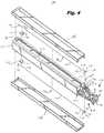
- FIG. 4is a perspective view, with parts separated, of the knotless suture retainer
- FIG. 5is a perspective view of a surgical suturing apparatus for use with the knotless suture retainer
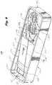
- FIG. 6is a partial top view illustrating the positioning of the surgical suturing apparatus in a loading unit of the knotless suture retainer
- FIG. 7is a view similar to FIG. 6 with jaws of the surgical suturing apparatus closed about a surgical needle held in the loading unit;
- FIG. 8is a perspective view of the surgical suturing apparatus removing the surgical needle and an associated length of suture from the knotless suture retainer;
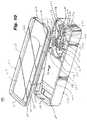
- FIG. 9is a perspective view of a second embodiment of a knotless suture retainer
- FIG. 10is a perspective view, with parts separated, of the knotless suture retainer of FIG. 9 ;
- FIG. 11is top view of the knotless suture retainer of FIG. 9 ;
- FIG. 12is a side view of the knotless suture retainer of FIG. 9 ;
- FIG. 13is a perspective view of a surgical suturing apparatus positioned in a loading unit of the knotless suture retainer of FIG. 9 ;
- FIG. 14is a perspective view of jaws of the surgical suturing apparatus closed about a surgical needle held in the loading unit;
- FIG. 15is a perspective view of the surgical suturing apparatus removing the surgical needle and an associated length of suture from the knotless suture retainer of FIG. 9 ;
- FIG. 16is a perspective view of a distal end of an alternate embodiment of a surgical suturing apparatus for use with the knotless suture retainer.
- proximalrefers to that part or component closer to the user
- distalrefers to that part or component further away from the user
- Suture retainer 10includes a generally rectangular, elongate body portion 12 having a planar tongue 14 extending proximally from a proximal end 16 of elongate body portion 12 .
- suture retainer 10is double-sided and includes a first or upper side 18 and a second or lower side 20 .
- Upper and lower sides 18 and 20are mirror images of each other including identical structure which function in an identical manner.
- a channel or suture tray 22is formed in a first side 24 of elongate body portion 12 .
- a first loading unit 26is provided on a first side 28 of planar tongue 14 .
- suture trayrefers to an elongate holder capable of supporting a relatively stiff length of suture material without substantial bending of the suture material.
- Suture tray 22 and first loading unit 26are provided to secure a suture assembly such as, for example, first suture assembly 30 within upper side 18 of elongate body portion 12 .
- First suture assembly 30generally includes a double-sided, surgical needle 32 which is retained within first loading unit 26 .
- First suture assembly 30additionally includes a length of suture material 34 having a proximal end 36 which is secured to surgical needle 32 .
- a distal end 38 of length of suture material 34includes a suture loop 40 .
- First suture assembly 30is configured to be self-locking. Specifically, length of suture material 34 is formed of a barbed material such that when surgical needle 32 is passed through suture loop 40 , the barbs (not shown) of suture material 34 may engage suture loop 40 to secure suture material 34 within suture loop 40 .
- suture retainer 10includes a first retainer, or first block 42 , positioned within first suture tray 22 .
- First block 42includes a center slit 44 to frictionally engage distal end 38 of length of suture material 34 to secure length of suture 34 within first suture tray 22 .
- First block 42is formed of a resilient material, such as, for example, foam, rubber, etc.
- first suture tray 22is defined by a first sidewall 46 , a second sidewall 48 , a proximal end wall 50 and a distal end wall 52 formed in upper side 18 of elongate body portion 12 .
- a proximal notch 54is provided in proximal wall 50 to allow length of suture material 34 to pass from within first suture tray 22 and extend toward needle 32 held within first loading unit 26 .
- a distal notch 56may be provided in distal wall 52 to facilitate removal of a suture cover (not shown) provided over first suture tray 22 .
- a plurality of tabs 58may be provided in first and second side walls 46 and 48 to retain the suture cover on elongate body portion 12 .
- suture retainer 10is double-sided and includes a second loading unit 60 provided on a second side 62 of planar tongue 14 . While not specifically shown, a second tray is formed in a second side 64 of elongate body portion 12 . It should be noted that the second tray and second loading unit 60 are substantially identical to first suture tray 22 and first loading unit 26 described herein.
- first loading unit 26is provided to support and supply double ended needle 32 to a surgical suturing apparatus.
- First loading unit 26includes a base 66 which may be affixed to first side 28 of planar tongue 14 or may be formed integrally with first side 28 .
- a needle support member 68extends vertically upwardly from base 66 and is configured to support surgical needle 32 in an elevated position relative to base 66 . This allows room for jaws of a surgical suturing apparatus (not shown) to be moved into engagement with surgical needle 32 .
- Apparatus receiving structure 70is provided on first loading unit 26 to properly position the surgical suturing apparatus with respect to surgical needle 32 .
- a needle block 72is provided on needle support member 68 to frictionally hold surgical needle 32 on needle support member 68 .
- needle block 72includes a needle notch 74 for receipt of surgical needle 32 .
- a recess 76is provided in base 66 for receipt of a distal end of the surgical suturing apparatus.
- a proximal end 78 of needle support member 68forms an abutment surface 80 to limit the advancement of the surgical suturing apparatus within first loading unit 26 .
- Apparatus alignment structure 82is additionally provided to guide surgical suturing apparatus within first loading unit 26 and generally includes a pair of first and second side tabs 84 and 86 which are configured to align an elongate member of the surgical suturing apparatus properly relative to surgical needle 32 .
- a support stud 88is additionally provided within recess 76 and is configured to engage a recess formed within the elongate member of the surgical suturing apparatus.
- first loading unit 26is provided with blocking structure 90 .
- Blocking structure 90generally includes a first blocking member 92 and a second blocking member 94 extending from base 66 adjacent needle support member 68 .
- First and second blocking members 92 and 94include respective vertical supports 96 and 98 and L-shaped proximally extending arms 100 and 102 located above surgical needle 32 .
- first and second blocking members 92 and 94 and, specifically, proximally extending arms 100 and 102prevent removal or lifting of surgical needle 32 from needle support member 68 until such time as surgical needle 32 has been properly grasped by the surgical suturing instrument and the jaws of the surgical suturing instrument are in a fully closed position.
- First and second proximally extending arms 100 and 102defining a proximal gap 104 there between which allows the fully closed the jaws of the surgical suturing instrument to be lifted vertically to thereby remove surgical needle 32 from needle block 72 .
- a distal gap 106is formed between first and second proximally extending arms 100 and 102 for passage of length of suture material 34 .
- Distal gap 106is in alignment with proximal notch 54 formed in elongate body portion 12 .
- suture retainer 10includes a second suture assembly 108 which is positioned within a second suture tray (not shown) formed in second or lower side 20 of elongate body portion 12 .
- Second suture assembly 108includes a length of suture material 110 having a double ended surgical needle 112 affixed to a proximal end 114 of length of suture material 110 .
- Length of suture material 110is substantially identical to that described herein above including a barbed outer surface and being formed of a relatively rigid material.
- a suture loop 116is formed at a distal end 118 of length of suture material 110 . Upon passage of surgical needle 112 through suture loop 116 , length of suture material 110 is self locking upon itself.
- Suture retainer 10additionally includes a second retainer or second block 120 having a slit 122 therein for receipt of proximal end 118 of length of suture material 110 to secure length of suture material 110 within the second tray (not shown).
- double ended surgical needle 32includes a pair of tissue penetrating tips 124 and 126 .
- Proximal end 36 of length of suture material 30is affixed to a center portion 128 of surgical needle 32 .
- a proximal end 114 of length of suture material 110is affixed to a center portion 130 of double ended surgical needle 112 .
- Double ended surgical needle 112also includes a pair of tissue penetrating tips 132 and 134 .
- Double ended surgical needle 112is secured within the second loading unit 60 in a manner substantially identical to secure a length of double ended surgical needle 32 within first loading unit 26 .
- suture retainer 110is provided with a pair of safety covers 136 and 138 which are configured to cover upper and lower sides 18 and 20 of suture retainer 10 .
- a length of covering materialmay be positioned beneath tabs 58 formed in first and second side walls 46 and 48 to protect first suture assembly 30 .
- a similar length of covering materialmay be positioned over the second tray to protect second suture assembly 108 .
- surgical suturing apparatus 140such as, for example, surgical suturing apparatus 140 to remove first suture assembly 30 from within suture retainer 10 will now be described.
- a particularly suitable surgical suturing apparatus 140is disclosed in U.S. Pat. No. 5,728,107 entitled “SURGICAL SUTURING APPARATUS WITH LOADING MECHANISM”, the entire disclosure of which is incorporated by reference herein.
- surgical suturing apparatus 140generally includes a body portion 142 having an elongate tubular member 144 extending distally from body portion 142 .
- a pair of needle grasping jawssuch as first and second jaws 146 and 148 , is pivotally mounted on a distal end 150 of elongate tubular member 142 .
- First and second jaws 146 and 148are movable from an open positioned substantially spaced apart to a closed position wherein first and second jaws 146 and 148 are substantially adjacent to each other.
- a pair of handles 152 and 154is provided on body portion 142 to move first and second jaws 146 and 148 between the open and closed positions.
- Needle holding recesses 156 and 158are formed within first and second jaws 146 and 148 , respectively, to receive and engage tissue penetrating tips 124 and 126 of surgical needle 32 .
- a toggle lever 160is provided to alternately secure surgical needle 32 within one of first and second jaws 146 and 148 .
- An override switch 162is provided to secure surgical needle 132 within needle recesses 156 and 158 when first and second jaws 146 and 148 are in a closed positioned so as to enable surgical suturing apparatus 140 to remove surgical needle 32 from first loading unit 26 .
- Surgical suturing apparatus 140is manipulated to position distal end 150 of elongate tubular member 144 within recess 76 formed in first loading unit 26 .
- Distal end 150is retained within first loading unit 26 by engagement with first and second tabs 84 and 86 .
- Distal end 150is advanced distally within first loading unit 26 until it engages abutment surface 80 formed on proximal end 78 of needle support member 68 .
- Distal end 150 of elongate tubular member 144is secured within first loading unit 26 by engagement with support stud 88 provided within recess 76 .
- handles 152 and 154are actuated to move first and second jaws 146 and 148 from the open to closed positions.
- tissue penetrating tips 124 and 126enter needle recesses 156 and 158 formed in first and second jaws 124 and 126 , respectively.
- Operation of toggle lever 160 and override switch 162function to secure surgical needle 32 within first and second jaws 146 and 148 .
- first and second jaws 146 and 148when first and second jaws 146 and 148 are in the closed position they may be lifted upwardly through gap 104 defined between first and second proximally extending arms 100 and 102 . Additionally, length of suture material 34 is free to pass upwardly through distal gap 106 defined between proximally extending arms 100 and 102 and through notch 54 are defined in proximal wall 50 upper side 18 of elongate body portion 12 . Continued lifting of elongate tubular member 144 will serve to draw length of suture material 34 out of first suture tray 22 and pull proximal end 38 of length of suture material 34 free from within center slit 44 in first retainer block 42 .
- suture retainer 10provides a safe and convenient method of supplying a suture assembly, including a double ended surgical needle having a length of relatively rigid suture material attached thereto, to surgical suturing apparatus 140 .
- Suture retainer 170generally includes an elongate body portion 172 defining a suture tray 174 and a loading unit 176 is positioned within a proximal tray portion 178 of suture tray 174 .
- a suture assembly 180similar to suture assembly 30 described herein above, is provided and includes a double ended, surgical needle 182 having a length of suture material 184 extending distally from surgical needle 182 .
- a proximal end 186 of length of suture material 184is affixed to double ended surgical needle 182 while a distal end 188 of length of suture material 184 terminates in a suture loop 190 .
- elongate body portion 172defines a suture tray 174 .
- Elongate body portion 172includes a proximal wall 192 and a distal wall 194 .
- First and second side walls 196 and 198extend between proximal wall 192 and distal wall 194 to define suture tray 174 .
- Suture tray 174includes a distal tray portion 200 , a central tray portion 202 and proximal tray portion 178 .
- Distal tray portion 200is connected to central tray portion 202 by a generally arcuate first transition tray portion 204 .
- central tray portion 202is connected to proximal tray portion 178 by a second transition tray portion 206 .
- Second transition tray portion 206forms a generally arcuate or U-shaped vertical wall 208 between proximal tray portion 178 and central tray portion 202 .
- proximal tray portion 178is partially vertically recessed relative to central tray portion 202 to contain loading unit 176 within elongate body portion 172 .
- suture retainer 170additionally includes a transparent cover 210 which is provided to protect suture assembly 180 prior to use.
- Cover 210includes a planner top surface 212 .
- a proximal edge 214 and a distal edge 216project downwardly from top surface 212 .
- First and second side edges 218 and 220extend between proximal edge 214 and distal edge 216 and also project downwardly from top surface 212 .
- Proximal edge 214 , distal edge 216 and first and second side edges 218 and 220overlie proximal wall 192 , distal wall 194 and first and second side walls 196 and 198 when cover 210 is positioned over elongate body portion 172 .
- suture retainer 170includes a loading unit 176 which is substantially identical to loading unit 26 described herein above with regard to suture retainer 10 .
- loading unit 176generally includes a base 222 having a needle support member 224 extending vertically upwardly from base 222 .
- Base 222may be positioned on proximal tray portion 178 or may be formed integrally therein.
- Apparatus receiving structure 226is provided on base 222 for receipt of a surgical suturing apparatus.
- a needle block 228is provided on needle support member 224 and includes a notch 230 ( FIG. 10 ) for receipt and support of surgical needle 182 .
- Apparatus receiving structure 226includes a recess 232 for receipt of distal end 150 of elongate tubular member 144 of surgical suturing apparatus 140 ( FIG. 5 ) a proximal end 234 of needle support member 224 forms and abutment surface 236 in order to limit the depth of insertion of surgical suturing apparatus 140 within loading unit 176 .
- a support stud 238is provided within recess 232 to secure surgical suturing apparatus 140 with a loading unit 176 and a manner substantially identical to that described herein above.
- Loading unit 176additionally includes alignment structure 240 to properly position first and second jaws 146 and 148 on distal end 150 of surgical suturing apparatus 140 adjacent surgical needle 182 .
- Alignment structure 240includes first and second side tabs 242 and 244 which are configured to engage elongate tubular member 144 .
- loading unit 176includes blocking structure 246 in the form of first and second blocking members 248 and 252 prevent removal of surgical needle 182 until it has been fully grasped within first and second jaws 146 and 148 of surgical suturing apparatus 140 .
- blocking members 248 and 252prevent removal of surgical suturing apparatus 140 from within loading unit 176 until first and second jaws 146 and 148 have been moved to the fully closed position.
- a gap 252is defined between first and second blocking members 248 and 250 in order to allow proximal end 186 of length of suture material 184 to be lifted clear of loading unit 176 .
- distal tray portion 200extends perpendicularly from distal wall 194 and is substantially parallel to a bottom surface 254 of elongate body portion 172 .
- central tray portion 202forms and angle ⁇ with bottom surface 254 and proximal tray portion 178 forms and angle ⁇ with bottom surface 254 .
- angles ⁇ and ⁇are illustrated as being substantially identical, it is contemplated herein that these angles may differ so as to support suture assembly 180 .
- a proximal end 256 of base 222is flush with a top edge 258 of proximal wall 192 . This elevates apparatus receiving structure 226 , and specifically side tabs 224 ( FIG. 11 ) and 244 above top edge 258 to allow surgical suturing apparatus 140 to be inserted into loading unit 176 .
- Surgical needle 182is removed from loading unit 176 in a manner substantially identical to that described herein above with regard to surgical needle 32 and loading unit 26 .
- surgical suturing apparatus 140is manipulated so as to advance distal end 150 within loading unit 176 .
- base 222is oriented at an angle ⁇ relative to elongate body portion 172
- elongate tubular member 144 of surgical suturing apparatus 140approaches loading unit 176 a corresponding angle ⁇ .
- Elongate tubular member 144is secured between tabs 242 and 244 on loading unit 176 .
- First and second jaws 146 and 148 of surgical suturing apparatusare positioned adjacent surgical needle 182 and beneath blocking members 248 and 250 .
- Handles 152 and 154 of surgical suturing apparatus 140are then manipulated to move jaws 146 and 148 from the open to the closed position passing under blocking members 248 and 250 .
- first and second jaws 146 and 148securely grasp surgical needle 182 ( FIG. 14 ).
- elongate tubular member 144 of surgical suturing apparatus 140may be lifted vertically to remove elongate tubular member 144 from between tabs 242 and 244 in order to lift surgical needle 182 out of notch 230 in needle block 228 . Additionally, a recess 260 formed in elongate tubular member 144 is lifted clear of support stud 238 . Jaws 146 and 148 pass upwardly between blocking members 248 and 250 thereby drawing proximal end 186 of length of suture material 184 upwardly through gap 252 defined between first and second blocking members 248 and 250 .
- suture assembly 180may be removed from suture tray 174 as length of suture material 184 is lifted off of central tray portion 202 and proximal end 180 , including suture loop 190 , is lifted free of distal tray portion 200 .
- suture retainer 170provides a secure and convenient method of supplying suture assembly 182 surgical suturing apparatus 140 .
- suture retainer 10has been shown and described for use with surgical stapling apparatus 140 , it is contemplated that suture retainer 10 may equally be used with a surgical suturing apparatus having a distal end or end effector 1000 , as shown in FIG. 16 .
- end effector 1000includes a neck assembly 1100 supported on a distal end of a shaft extending from a handle assembly, and a tool assembly 1200 supported on a distal end of neck assembly 1100 .
- Neck assembly 1100includes a plurality of joints 1120 each including a distal knuckle 1120 a and a proximal clevis 1120 b formed therewith. Each knuckle 1120 a operatively engages a clevis 1120 b of an adjacent joint 1120 .
- Each joint 1120defines a central lumen (not shown) formed therein and a pair of opposed lumens (not shown) formed on either side of central lumen.
- a pair of articulation cables 1140 a , 1140 bslidably extend through respective lumens of joints 1120 .
- Neck assembly 1100enables end effector 1000 to articulate
- tool assembly 1200 of end effector 1000includes a jaw support member 1220 , and a pair of jaws 1300 , 1320 mounted for pivotable movement on jaw support member 1220 .
- Each jaw 1300 , 1320includes a needle receiving recess 1300 a , 1320 a , respectively, configured to surround and hold at least a portion of a surgical needle disposed therein substantially perpendicular to tissue engaging surfaces thereof.
- end effector 1000For a more detailed discussion of the construction and operation of end effector 1000 , reference may be made to International Patent Application No. PCT/US07/21457, filed on Oct. 5, 2007, entitled “FLEXIBLE ENDOSCOPIC STITCHING DEVICES”, the entire disclosure of which is incorporated by reference herein.
- the disclosed suture traysneed not be planner but may present other cross-sections such as, for example, arcuate etc.
- the disclosed suture retainersare described with regard to a double ended surgical needle, single ended surgical needles are also contemplated as are surgical suturing apparatus capable of manipulating single ended surgical needles.
- the disclosed suture retaineris may be configured to provide more than one suture assembly to a surgical suturing apparatus. Therefore, the above description should not be construed as limiting, but merely as exemplifications of particular embodiments. Those skilled in the art will envision other modifications within the scope and spirit of the claims appended hereto.
Landscapes
- Health & Medical Sciences (AREA)
- Surgery (AREA)
- Life Sciences & Earth Sciences (AREA)
- Biomedical Technology (AREA)
- Nuclear Medicine, Radiotherapy & Molecular Imaging (AREA)
- Engineering & Computer Science (AREA)
- Heart & Thoracic Surgery (AREA)
- Medical Informatics (AREA)
- Molecular Biology (AREA)
- Animal Behavior & Ethology (AREA)
- General Health & Medical Sciences (AREA)
- Public Health (AREA)
- Veterinary Medicine (AREA)
- Dentistry (AREA)
- Surgical Instruments (AREA)
Abstract
Description
Claims (18)
Priority Applications (1)
| Application Number | Priority Date | Filing Date | Title |
|---|---|---|---|
| US15/920,633US11045185B2 (en) | 2009-04-14 | 2018-03-14 | Knotless endostitch suture retainer |
Applications Claiming Priority (3)
| Application Number | Priority Date | Filing Date | Title |
|---|---|---|---|
| US16902609P | 2009-04-14 | 2009-04-14 | |
| US12/726,434US9943306B2 (en) | 2009-04-14 | 2010-03-18 | Knotless endostitch suture retainer |
| US15/920,633US11045185B2 (en) | 2009-04-14 | 2018-03-14 | Knotless endostitch suture retainer |
Related Parent Applications (1)
| Application Number | Title | Priority Date | Filing Date |
|---|---|---|---|
| US12/726,434DivisionUS9943306B2 (en) | 2009-04-14 | 2010-03-18 | Knotless endostitch suture retainer |
Publications (2)
| Publication Number | Publication Date |
|---|---|
| US20180199933A1 US20180199933A1 (en) | 2018-07-19 |
| US11045185B2true US11045185B2 (en) | 2021-06-29 |
Family
ID=42269634
Family Applications (2)
| Application Number | Title | Priority Date | Filing Date |
|---|---|---|---|
| US12/726,434Active2032-07-12US9943306B2 (en) | 2009-04-14 | 2010-03-18 | Knotless endostitch suture retainer |
| US15/920,633Expired - Fee RelatedUS11045185B2 (en) | 2009-04-14 | 2018-03-14 | Knotless endostitch suture retainer |
Family Applications Before (1)
| Application Number | Title | Priority Date | Filing Date |
|---|---|---|---|
| US12/726,434Active2032-07-12US9943306B2 (en) | 2009-04-14 | 2010-03-18 | Knotless endostitch suture retainer |
Country Status (5)
| Country | Link |
|---|---|
| US (2) | US9943306B2 (en) |
| EP (1) | EP2241264B1 (en) |
| JP (1) | JP5595094B2 (en) |
| AU (1) | AU2010201352B2 (en) |
| CA (1) | CA2699141C (en) |
Families Citing this family (8)
| Publication number | Priority date | Publication date | Assignee | Title |
|---|---|---|---|---|
| US20110040308A1 (en)* | 2008-06-13 | 2011-02-17 | Ramiro Cabrera | Endoscopic Stitching Devices |
| US9943306B2 (en) | 2009-04-14 | 2018-04-17 | Covidien Lp | Knotless endostitch suture retainer |
| EP2429374B1 (en) | 2009-05-01 | 2013-09-25 | Cook Medical Technologies LLC | Medical device for suturing perforations |
| CN105395227B (en)* | 2015-12-31 | 2018-02-06 | 张选锋 | A kind of needle forceps for automatic sewing |
| US20180256160A1 (en)* | 2017-03-09 | 2018-09-13 | Dura Tap Llc | Loading fixture for a suturing device and method for loading same |
| US11219449B2 (en) | 2019-02-22 | 2022-01-11 | Ethicon, Inc. | Suture needle packages for loading suture needles and methods of passing suture needles through trocars |
| US20230135885A1 (en)* | 2021-08-27 | 2023-05-04 | Maruho Medical, Inc. | Method and apparatus for loading and/or unloading suture and/or a shuttle |
| WO2024186996A2 (en)* | 2023-03-09 | 2024-09-12 | Noah Medical Corporation | Systems and methods for robotic endoluminal suturing instrument |
Citations (79)
| Publication number | Priority date | Publication date | Assignee | Title |
|---|---|---|---|---|
| US2012776A (en) | 1931-05-23 | 1935-08-27 | Roeder Hans Albert | Ligator |
| US2692676A (en) | 1952-03-31 | 1954-10-26 | Davis & Geck Inc | Suture needle package |
| US3106417A (en) | 1962-03-16 | 1963-10-08 | Donald J Clow | Knot tying device |
| US3521918A (en) | 1968-08-14 | 1970-07-28 | Richard L Hammond | Fishline knotting fixture and cutter |
| US3580256A (en) | 1969-06-30 | 1971-05-25 | Jack E Wilkinson | Pre-tied suture and method of suturing |
| US3752516A (en) | 1971-12-07 | 1973-08-14 | P Mumma | Knot tying jig |
| US4120395A (en) | 1977-09-02 | 1978-10-17 | Ethicon, Inc. | Package for double-armed sutures |
| EP0055823A1 (en) | 1980-12-12 | 1982-07-14 | American Cyanamid Company | Package for surgical sutures |
| US4711476A (en) | 1986-11-21 | 1987-12-08 | Helen L. Hanson | Knot |
| US5350060A (en) | 1993-01-15 | 1994-09-27 | Ethicon, Inc. | Procedure kit and package |
| US5358498A (en) | 1990-02-01 | 1994-10-25 | Deknatel Technology Corporation, Inc. | Needled suture |
| US5389103A (en) | 1991-07-23 | 1995-02-14 | Kernforschungszentrum Karlsruhe Gmbh | Surgical stitching apparatus |
| US5391176A (en) | 1993-06-02 | 1995-02-21 | General Surgical Innovations, Inc. | Surgical instrument for tying a knot in a length of suture at a remote location |
| US5405352A (en) | 1991-04-09 | 1995-04-11 | Weston; Peter V. | Suture knot, method for its formation and use, and knot forming apparatus |
| US5472446A (en) | 1993-06-02 | 1995-12-05 | De La Torre; Roger A. | Surgical instrument for tying a knot in a length of suture at a remote location |
| US5478345A (en) | 1994-08-19 | 1995-12-26 | United States Surgical Corporation | Mechanism for endoscopic suturing device |
| US5478344A (en) | 1993-10-08 | 1995-12-26 | United States Surgical Corporation | Surgical suturing apparatus with loading mechanism |
| US5480406A (en) | 1994-10-07 | 1996-01-02 | United States Surgical Corporation | Method of employing surgical suturing apparatus to tie knots |
| US5527323A (en) | 1993-06-02 | 1996-06-18 | General Surgical Innovations, Inc. | Surgical instrument for tying a knot in a length of suture at a remote location |
| US5540703A (en) | 1993-01-06 | 1996-07-30 | Smith & Nephew Richards Inc. | Knotted cable attachment apparatus formed of braided polymeric fibers |
| EP0726062A2 (en) | 1995-02-10 | 1996-08-14 | Ethicon, Inc. | Center dispense suture package |
| US5562686A (en) | 1995-04-19 | 1996-10-08 | United States Surgical Corporation | Apparaus and method for suturing body tissue |
| US5566822A (en) | 1993-12-09 | 1996-10-22 | United States Surgical Corporation | Suture retainer |
| US5569301A (en) | 1993-10-08 | 1996-10-29 | United States Surgical Corporation | Surgical incision members for endoscopic suturing apparatus |
| US5571090A (en) | 1994-10-07 | 1996-11-05 | United States Surgical Corporation | Vascular suturing apparatus |
| US5573286A (en) | 1995-03-15 | 1996-11-12 | Rogozinski; Chaim | Knot |
| US5601185A (en) | 1994-08-16 | 1997-02-11 | Ethicon, Inc. | Package with surgical suture material |
| US5630825A (en) | 1995-04-27 | 1997-05-20 | De La Torre; Roger A. | Magazine for loading a needle onto a stitching instrument and for loading a length of suture onto a suture dispensing instrument |
| US5632751A (en) | 1995-07-28 | 1997-05-27 | Piraka; Hadi A. | Surgical suturing device |
| WO1997022300A1 (en) | 1995-12-18 | 1997-06-26 | General Surgical Innovations, Inc. | Magazine for loading a needle and suture |
| US5643293A (en) | 1993-12-29 | 1997-07-01 | Olympus Optical Co., Ltd. | Suturing instrument |
| US5669490A (en) | 1995-06-07 | 1997-09-23 | United States Surgical Corporation | Suture retainer |
| US5674230A (en) | 1993-10-08 | 1997-10-07 | United States Surgical Corporation | Surgical suturing apparatus with locking mechanisms |
| US5674229A (en) | 1993-10-08 | 1997-10-07 | United States Surgical Corporation | Surgical suturing apparatus with loading mechanism |
| US5681331A (en) | 1993-06-02 | 1997-10-28 | De La Torre; Roger A. | Surgical instrument for tying a knot in a length of suture at a remote location |
| US5715942A (en) | 1996-11-15 | 1998-02-10 | Li Medical Technologies, Inc. | Package and holder for suture anchor with sutures and surgical needles attacked |
| US5728109A (en) | 1997-04-08 | 1998-03-17 | Ethicon Endo-Surgery, Inc. | Surgical knot and method for its formation |
| US5730747A (en) | 1995-06-07 | 1998-03-24 | Smith & Nephew, Inc. | Suture passing forceps |
| US5733293A (en) | 1996-05-08 | 1998-03-31 | United States Surgical Corporation | Disposable loading unit for a vascular suturing instrument |
| US5749898A (en) | 1997-04-08 | 1998-05-12 | Ethicon Endo-Surgery, Inc. | Suture cartridge assembly for a surgical knot |
| US5792153A (en) | 1994-03-23 | 1998-08-11 | University College London | Sewing device |
| US5797928A (en) | 1995-01-20 | 1998-08-25 | Olympus Optical Co., Ltd. | Ligating apparatus |
| US5814069A (en) | 1997-04-08 | 1998-09-29 | Ethicon Endo-Surgery, Inc. | Load assist device for a suture cartridge |
| US5814054A (en) | 1996-09-23 | 1998-09-29 | Symbiosis Corporation | Automatic needle-passer suturing instrument |
| WO1998053745A1 (en) | 1997-05-27 | 1998-12-03 | United States Surgical Corporation | Stitching devices for heart valve replacement surgery |
| US5865836A (en) | 1996-09-20 | 1999-02-02 | United States Surgical Corporation | Needle-suture combination |
| US5893592A (en) | 1997-04-08 | 1999-04-13 | Ethicon Endo-Surgery, Inc. | Partially tied surgical knot |
| US5894921A (en) | 1997-10-07 | 1999-04-20 | Ethicon, Inc. | Package for suture anchor |
| US5941430A (en) | 1997-03-10 | 1999-08-24 | Clover Mfg. Co., Ltd. | Holder for sewing needles |
| JPH11299797A (en) | 1998-04-15 | 1999-11-02 | Azwell Inc | Suture package |
| US6016905A (en) | 1998-03-06 | 2000-01-25 | United States Surgical Corporation | Surgical suture retainer package |
| US6056771A (en) | 1995-06-02 | 2000-05-02 | United States Surgical Corporation | Radiused tip surgical needles and surgical incision members |
| US6126666A (en) | 1997-04-14 | 2000-10-03 | Forschungszcutrum Karlsruhe Gmbh | Device for inserting a surgical suture needle into an endoscopic suture apparatus |
| US6138440A (en)* | 1998-03-06 | 2000-10-31 | United States Surgical Corporation | Surgical suture retainer package |
| US6277132B1 (en) | 1997-10-24 | 2001-08-21 | Forschungszentrum Karlsruhe, Gmbh | Needle inserter with a needle protection device |
| US6533796B1 (en) | 2000-10-11 | 2003-03-18 | Lsi Solutions, Inc. | Loader for surgical suturing instrument |
| US6596015B1 (en) | 1999-07-13 | 2003-07-22 | Loma Linda University Medical Center | Methods and apparatus for annealing sutures |
| US20030195529A1 (en) | 2002-04-15 | 2003-10-16 | Shinichi Takamoto | Intracardiac suture device |
| US6719765B2 (en) | 2001-12-03 | 2004-04-13 | Bonutti 2003 Trust-A | Magnetic suturing system and method |
| US20050154403A1 (en) | 2004-01-14 | 2005-07-14 | Lsi Solutions, Inc. | Running stitch suturing device |
| US6991635B2 (en) | 2001-10-01 | 2006-01-31 | Nipro Corporation | Intracardiac suture device |
| JP2006036227A (en) | 2004-07-22 | 2006-02-09 | Kenei Pharmaceutical Co Ltd | Cotton swab container |
| US7191900B2 (en) | 2003-06-03 | 2007-03-20 | Js Vascular, Inc. | Guide wire containment and dispensing apparatus |
| US7192437B2 (en) | 1999-03-17 | 2007-03-20 | Poly Med Inc | High strength fibers of l-lactide copolymers, ε-caprolactone, and trimethylene carbonate and absorbable medical constructs thereof |
| US7218972B2 (en) | 2003-04-07 | 2007-05-15 | Cardiac Pacemakers, Inc. | Extra strength suture sleeve |
| US7232448B2 (en) | 2004-06-17 | 2007-06-19 | Ethicon, Inc. - Usa | Minimally invasive stitching device |
| US7244260B2 (en) | 2001-09-18 | 2007-07-17 | Kosek Medical K.K. | Apparatus for holding and arranging threads in surgical operations |
| US7309346B2 (en) | 2000-09-15 | 2007-12-18 | United States Surgical Corporation | Knotless tissue anchor |
| WO2008045394A2 (en) | 2006-10-05 | 2008-04-17 | Tyco Healthcare Group Lp | Flexible endoscopic stitching devices |
| US20080140118A1 (en) | 2001-09-13 | 2008-06-12 | United States Surgical Corporation | Knotless tissue anchor |
| US7468068B2 (en) | 2004-06-30 | 2008-12-23 | Alwin Kolster | Suture for wound closure, tissue approximation, tissue support, suspension and/or fixation |
| US20090138029A1 (en) | 2007-11-05 | 2009-05-28 | Revolutionary Surgical Devices, Llc | Suture passing instrument and method |
| US20090248046A1 (en) | 2002-10-04 | 2009-10-01 | Tyco Healthcare Group Lp | Surgical suturing apparatus with measurement structure |
| US7601164B2 (en) | 2004-04-07 | 2009-10-13 | Tze Liang Woffles Wu | Surgical thread |
| US20090259233A1 (en) | 2008-04-11 | 2009-10-15 | Michael Bogart | Deployment System For Surgical Suture |
| EP2113205A2 (en) | 2008-04-07 | 2009-11-04 | Tyco Healthcare Group LP | Suture packaging for barbed sutures |
| US20100307934A1 (en) | 2009-06-09 | 2010-12-09 | Tyco Healthcare Group Lp | Knotless Endostitch Package |
| US20110042244A1 (en) | 2009-08-20 | 2011-02-24 | David Kirsch | Endostitch packages |
| US9943306B2 (en) | 2009-04-14 | 2018-04-17 | Covidien Lp | Knotless endostitch suture retainer |
Family Cites Families (1)
| Publication number | Priority date | Publication date | Assignee | Title |
|---|---|---|---|---|
| US7637369B2 (en)* | 2003-07-18 | 2009-12-29 | Tyco Healthcare Group Lp | Suture packaging |
- 2010
- 2010-03-18USUS12/726,434patent/US9943306B2/enactiveActive
- 2010-04-06AUAU2010201352Apatent/AU2010201352B2/ennot_activeCeased
- 2010-04-07CACA2699141Apatent/CA2699141C/ennot_activeExpired - Fee Related
- 2010-04-12JPJP2010091735Apatent/JP5595094B2/ennot_activeExpired - Fee Related
- 2010-04-13EPEP10250763.9Apatent/EP2241264B1/enactiveActive
- 2018
- 2018-03-14USUS15/920,633patent/US11045185B2/ennot_activeExpired - Fee Related
Patent Citations (96)
| Publication number | Priority date | Publication date | Assignee | Title |
|---|---|---|---|---|
| US2012776A (en) | 1931-05-23 | 1935-08-27 | Roeder Hans Albert | Ligator |
| US2692676A (en) | 1952-03-31 | 1954-10-26 | Davis & Geck Inc | Suture needle package |
| US3106417A (en) | 1962-03-16 | 1963-10-08 | Donald J Clow | Knot tying device |
| US3521918A (en) | 1968-08-14 | 1970-07-28 | Richard L Hammond | Fishline knotting fixture and cutter |
| US3580256A (en) | 1969-06-30 | 1971-05-25 | Jack E Wilkinson | Pre-tied suture and method of suturing |
| US3752516A (en) | 1971-12-07 | 1973-08-14 | P Mumma | Knot tying jig |
| US4120395A (en) | 1977-09-02 | 1978-10-17 | Ethicon, Inc. | Package for double-armed sutures |
| EP0055823A1 (en) | 1980-12-12 | 1982-07-14 | American Cyanamid Company | Package for surgical sutures |
| US4711476A (en) | 1986-11-21 | 1987-12-08 | Helen L. Hanson | Knot |
| US5358498A (en) | 1990-02-01 | 1994-10-25 | Deknatel Technology Corporation, Inc. | Needled suture |
| US5405352A (en) | 1991-04-09 | 1995-04-11 | Weston; Peter V. | Suture knot, method for its formation and use, and knot forming apparatus |
| US5389103A (en) | 1991-07-23 | 1995-02-14 | Kernforschungszentrum Karlsruhe Gmbh | Surgical stitching apparatus |
| US5628756A (en) | 1993-01-06 | 1997-05-13 | Smith & Nephew Richards Inc. | Knotted cable attachment apparatus formed of braided polymeric fibers |
| US5540703A (en) | 1993-01-06 | 1996-07-30 | Smith & Nephew Richards Inc. | Knotted cable attachment apparatus formed of braided polymeric fibers |
| US5350060A (en) | 1993-01-15 | 1994-09-27 | Ethicon, Inc. | Procedure kit and package |
| US5391176A (en) | 1993-06-02 | 1995-02-21 | General Surgical Innovations, Inc. | Surgical instrument for tying a knot in a length of suture at a remote location |
| US5472446A (en) | 1993-06-02 | 1995-12-05 | De La Torre; Roger A. | Surgical instrument for tying a knot in a length of suture at a remote location |
| US5527323A (en) | 1993-06-02 | 1996-06-18 | General Surgical Innovations, Inc. | Surgical instrument for tying a knot in a length of suture at a remote location |
| US5681331A (en) | 1993-06-02 | 1997-10-28 | De La Torre; Roger A. | Surgical instrument for tying a knot in a length of suture at a remote location |
| US5674230A (en) | 1993-10-08 | 1997-10-07 | United States Surgical Corporation | Surgical suturing apparatus with locking mechanisms |
| US5478344A (en) | 1993-10-08 | 1995-12-26 | United States Surgical Corporation | Surgical suturing apparatus with loading mechanism |
| US5728107A (en) | 1993-10-08 | 1998-03-17 | United States Surgical Corporation | Surgical suturing apparatus with loading mechanism |
| US5871488A (en) | 1993-10-08 | 1999-02-16 | United States Surgical Corporation | Surgical suturing apparatus with locking mechanisms |
| US5674229A (en) | 1993-10-08 | 1997-10-07 | United States Surgical Corporation | Surgical suturing apparatus with loading mechanism |
| US5569301A (en) | 1993-10-08 | 1996-10-29 | United States Surgical Corporation | Surgical incision members for endoscopic suturing apparatus |
| US5591181A (en) | 1993-10-08 | 1997-01-07 | United States Surgical Corporation | Surgical suturing apparatus with loading mechanism |
| US5566822A (en) | 1993-12-09 | 1996-10-22 | United States Surgical Corporation | Suture retainer |
| US5643293A (en) | 1993-12-29 | 1997-07-01 | Olympus Optical Co., Ltd. | Suturing instrument |
| US5792153A (en) | 1994-03-23 | 1998-08-11 | University College London | Sewing device |
| US5601185A (en) | 1994-08-16 | 1997-02-11 | Ethicon, Inc. | Package with surgical suture material |
| JPH0866404A (en) | 1994-08-19 | 1996-03-12 | United States Surgical Corp | Sutural device for surgical operation,which is equipped withcharging mechanism |
| US5478345A (en) | 1994-08-19 | 1995-12-26 | United States Surgical Corporation | Mechanism for endoscopic suturing device |
| US5571090A (en) | 1994-10-07 | 1996-11-05 | United States Surgical Corporation | Vascular suturing apparatus |
| US5480406A (en) | 1994-10-07 | 1996-01-02 | United States Surgical Corporation | Method of employing surgical suturing apparatus to tie knots |
| US5797928A (en) | 1995-01-20 | 1998-08-25 | Olympus Optical Co., Ltd. | Ligating apparatus |
| EP0726062A2 (en) | 1995-02-10 | 1996-08-14 | Ethicon, Inc. | Center dispense suture package |
| US5573286A (en) | 1995-03-15 | 1996-11-12 | Rogozinski; Chaim | Knot |
| US5562686A (en) | 1995-04-19 | 1996-10-08 | United States Surgical Corporation | Apparaus and method for suturing body tissue |
| US5755729A (en) | 1995-04-27 | 1998-05-26 | General Surgical Innovations, Inc. | Magazine for loading a needle and a length of suture onto a surgical instrument |
| US5630825A (en) | 1995-04-27 | 1997-05-20 | De La Torre; Roger A. | Magazine for loading a needle onto a stitching instrument and for loading a length of suture onto a suture dispensing instrument |
| US6056771A (en) | 1995-06-02 | 2000-05-02 | United States Surgical Corporation | Radiused tip surgical needles and surgical incision members |
| US5669490A (en) | 1995-06-07 | 1997-09-23 | United States Surgical Corporation | Suture retainer |
| US5730747A (en) | 1995-06-07 | 1998-03-24 | Smith & Nephew, Inc. | Suture passing forceps |
| US5632751A (en) | 1995-07-28 | 1997-05-27 | Piraka; Hadi A. | Surgical suturing device |
| WO1997022300A1 (en) | 1995-12-18 | 1997-06-26 | General Surgical Innovations, Inc. | Magazine for loading a needle and suture |
| US5733293A (en) | 1996-05-08 | 1998-03-31 | United States Surgical Corporation | Disposable loading unit for a vascular suturing instrument |
| US5865836A (en) | 1996-09-20 | 1999-02-02 | United States Surgical Corporation | Needle-suture combination |
| US5814054A (en) | 1996-09-23 | 1998-09-29 | Symbiosis Corporation | Automatic needle-passer suturing instrument |
| US5715942A (en) | 1996-11-15 | 1998-02-10 | Li Medical Technologies, Inc. | Package and holder for suture anchor with sutures and surgical needles attacked |
| US5941430A (en) | 1997-03-10 | 1999-08-24 | Clover Mfg. Co., Ltd. | Holder for sewing needles |
| US5814069A (en) | 1997-04-08 | 1998-09-29 | Ethicon Endo-Surgery, Inc. | Load assist device for a suture cartridge |
| US5893592A (en) | 1997-04-08 | 1999-04-13 | Ethicon Endo-Surgery, Inc. | Partially tied surgical knot |
| US5749898A (en) | 1997-04-08 | 1998-05-12 | Ethicon Endo-Surgery, Inc. | Suture cartridge assembly for a surgical knot |
| US5728109A (en) | 1997-04-08 | 1998-03-17 | Ethicon Endo-Surgery, Inc. | Surgical knot and method for its formation |
| US6126666A (en) | 1997-04-14 | 2000-10-03 | Forschungszcutrum Karlsruhe Gmbh | Device for inserting a surgical suture needle into an endoscopic suture apparatus |
| US5908428A (en) | 1997-05-27 | 1999-06-01 | United States Surgical Corporation | Stitching devices for heart valve replacement surgery |
| WO1998053745A1 (en) | 1997-05-27 | 1998-12-03 | United States Surgical Corporation | Stitching devices for heart valve replacement surgery |
| US5894921A (en) | 1997-10-07 | 1999-04-20 | Ethicon, Inc. | Package for suture anchor |
| US6277132B1 (en) | 1997-10-24 | 2001-08-21 | Forschungszentrum Karlsruhe, Gmbh | Needle inserter with a needle protection device |
| US6016905A (en) | 1998-03-06 | 2000-01-25 | United States Surgical Corporation | Surgical suture retainer package |
| US6138440A (en)* | 1998-03-06 | 2000-10-31 | United States Surgical Corporation | Surgical suture retainer package |
| JPH11299797A (en) | 1998-04-15 | 1999-11-02 | Azwell Inc | Suture package |
| US7192437B2 (en) | 1999-03-17 | 2007-03-20 | Poly Med Inc | High strength fibers of l-lactide copolymers, ε-caprolactone, and trimethylene carbonate and absorbable medical constructs thereof |
| US6596015B1 (en) | 1999-07-13 | 2003-07-22 | Loma Linda University Medical Center | Methods and apparatus for annealing sutures |
| US7309346B2 (en) | 2000-09-15 | 2007-12-18 | United States Surgical Corporation | Knotless tissue anchor |
| US6533796B1 (en) | 2000-10-11 | 2003-03-18 | Lsi Solutions, Inc. | Loader for surgical suturing instrument |
| US20080140118A1 (en) | 2001-09-13 | 2008-06-12 | United States Surgical Corporation | Knotless tissue anchor |
| US7244260B2 (en) | 2001-09-18 | 2007-07-17 | Kosek Medical K.K. | Apparatus for holding and arranging threads in surgical operations |
| US6991635B2 (en) | 2001-10-01 | 2006-01-31 | Nipro Corporation | Intracardiac suture device |
| US6719765B2 (en) | 2001-12-03 | 2004-04-13 | Bonutti 2003 Trust-A | Magnetic suturing system and method |
| US20030195529A1 (en) | 2002-04-15 | 2003-10-16 | Shinichi Takamoto | Intracardiac suture device |
| US7063710B2 (en) | 2002-04-15 | 2006-06-20 | Nipro Corporation | Intracardiac suture device |
| US20090248046A1 (en) | 2002-10-04 | 2009-10-01 | Tyco Healthcare Group Lp | Surgical suturing apparatus with measurement structure |
| US7218972B2 (en) | 2003-04-07 | 2007-05-15 | Cardiac Pacemakers, Inc. | Extra strength suture sleeve |
| US7191900B2 (en) | 2003-06-03 | 2007-03-20 | Js Vascular, Inc. | Guide wire containment and dispensing apparatus |
| US7211093B2 (en) | 2004-01-14 | 2007-05-01 | Lsi Solutions, Inc. | Sew-right running stitch instrument |
| US20050154402A1 (en) | 2004-01-14 | 2005-07-14 | Lsi Solutions, Inc. | Sew-right running stitch instrument |
| US20050154403A1 (en) | 2004-01-14 | 2005-07-14 | Lsi Solutions, Inc. | Running stitch suturing device |
| US7601164B2 (en) | 2004-04-07 | 2009-10-13 | Tze Liang Woffles Wu | Surgical thread |
| US7232448B2 (en) | 2004-06-17 | 2007-06-19 | Ethicon, Inc. - Usa | Minimally invasive stitching device |
| US7468068B2 (en) | 2004-06-30 | 2008-12-23 | Alwin Kolster | Suture for wound closure, tissue approximation, tissue support, suspension and/or fixation |
| JP2006036227A (en) | 2004-07-22 | 2006-02-09 | Kenei Pharmaceutical Co Ltd | Cotton swab container |
| WO2008045385A2 (en) | 2006-10-05 | 2008-04-17 | Tyco Healthcare Group Lp | Flexible endoscopic stitching devices |
| WO2008045333A2 (en) | 2006-10-05 | 2008-04-17 | Tyco Healthcare Group Lp | Flexible endoscopic stitching devices |
| WO2008045361A2 (en) | 2006-10-05 | 2008-04-17 | Tyco Healthcare Group Lp | Flexible endoscopic stitching devices |
| WO2008045386A2 (en) | 2006-10-05 | 2008-04-17 | Tyco Healthcare Group Lp | Flexible endoscopic stitching devices |
| WO2008045367A2 (en) | 2006-10-05 | 2008-04-17 | Tyco Healthcare Group Lp | Flexible endoscopic stitching devices |
| WO2008045353A2 (en) | 2006-10-05 | 2008-04-17 | Tyco Healthcare Group Lp | Flexible endoscopic stitching devices |
| WO2008045394A2 (en) | 2006-10-05 | 2008-04-17 | Tyco Healthcare Group Lp | Flexible endoscopic stitching devices |
| WO2008045355A2 (en) | 2006-10-05 | 2008-04-17 | Tyco Healthcare Group Lp | Flexible endoscopic stitching devices |
| US20090138029A1 (en) | 2007-11-05 | 2009-05-28 | Revolutionary Surgical Devices, Llc | Suture passing instrument and method |
| EP2113205A2 (en) | 2008-04-07 | 2009-11-04 | Tyco Healthcare Group LP | Suture packaging for barbed sutures |
| US20090259233A1 (en) | 2008-04-11 | 2009-10-15 | Michael Bogart | Deployment System For Surgical Suture |
| US9943306B2 (en) | 2009-04-14 | 2018-04-17 | Covidien Lp | Knotless endostitch suture retainer |
| US20100307934A1 (en) | 2009-06-09 | 2010-12-09 | Tyco Healthcare Group Lp | Knotless Endostitch Package |
| US20110042244A1 (en) | 2009-08-20 | 2011-02-24 | David Kirsch | Endostitch packages |
Non-Patent Citations (4)
| Title |
|---|
| Canadian Office Action dated Mar. 1, 2016 in corresponding Canadian Patent Application No. 2,699,141. |
| European Office Action corresponding to EP 10 250 763.9 dated Jul. 24, 2015; 5 pp. |
| European Search Report for EP 10250763.9-1269 dated Jun. 28, 2010 (3 pages). |
| Japanese Office Action issued in Japanese Patent Application No. 2010-091735, dated Dec. 4, 2013. |
Also Published As
| Publication number | Publication date |
|---|---|
| CA2699141A1 (en) | 2010-10-14 |
| AU2010201352B2 (en) | 2015-05-14 |
| EP2241264B1 (en) | 2019-08-07 |
| US20100262165A1 (en) | 2010-10-14 |
| CA2699141C (en) | 2018-02-13 |
| JP2010246921A (en) | 2010-11-04 |
| JP5595094B2 (en) | 2014-09-24 |
| US9943306B2 (en) | 2018-04-17 |
| US20180199933A1 (en) | 2018-07-19 |
| AU2010201352A1 (en) | 2010-10-28 |
| EP2241264A1 (en) | 2010-10-20 |
Similar Documents
| Publication | Publication Date | Title |
|---|---|---|
| US11045185B2 (en) | Knotless endostitch suture retainer | |
| EP2260774B1 (en) | Knotless endostitch package | |
| US11399834B2 (en) | Tissue apposition clip application methods | |
| US12114866B2 (en) | Interoperative clip loading device | |
| US10595856B2 (en) | Stitching device with long needle delivery | |
| US6986780B2 (en) | Surgical element delivery system and method | |
| RU2619379C2 (en) | Surgical instruments and reinforcing material | |
| US20190328399A1 (en) | Latch assemblies and surgical instruments including the same | |
| US20140058415A1 (en) | Wound closure device including direct-driven needle | |
| EP1804692A1 (en) | Multipurpose surgical tool | |
| US12285176B2 (en) | Multi-piece ligation clip | |
| CN111616762B (en) | Surgical stapling device with independently movable jaws | |
| US20240358365A1 (en) | Suture retrieval systems and methods | |
| US20250295417A1 (en) | Surgical clip cartridge and method of use | |
| US20200337691A1 (en) | Port site incision closure device |
Legal Events
| Date | Code | Title | Description |
|---|---|---|---|
| AS | Assignment | Owner name:TYCO HEALTHCARE GROUP LP, MASSACHUSETTS Free format text:ASSIGNMENT OF ASSIGNORS INTEREST;ASSIGNOR:KIRSCH, DAVID;REEL/FRAME:045201/0987 Effective date:20100318 Owner name:COVIDIEN LP, MASSACHUSETTS Free format text:CHANGE OF NAME;ASSIGNOR:TYCO HEALTHCARE GROUP LP;REEL/FRAME:045586/0404 Effective date:20120928 | |
| FEPP | Fee payment procedure | Free format text:ENTITY STATUS SET TO UNDISCOUNTED (ORIGINAL EVENT CODE: BIG.); ENTITY STATUS OF PATENT OWNER: LARGE ENTITY | |
| STPP | Information on status: patent application and granting procedure in general | Free format text:DOCKETED NEW CASE - READY FOR EXAMINATION | |
| STPP | Information on status: patent application and granting procedure in general | Free format text:NON FINAL ACTION MAILED | |
| STPP | Information on status: patent application and granting procedure in general | Free format text:DOCKETED NEW CASE - READY FOR EXAMINATION | |
| STPP | Information on status: patent application and granting procedure in general | Free format text:NOTICE OF ALLOWANCE MAILED -- APPLICATION RECEIVED IN OFFICE OF PUBLICATIONS | |
| STPP | Information on status: patent application and granting procedure in general | Free format text:PUBLICATIONS -- ISSUE FEE PAYMENT RECEIVED | |
| STPP | Information on status: patent application and granting procedure in general | Free format text:PUBLICATIONS -- ISSUE FEE PAYMENT VERIFIED | |
| STCF | Information on status: patent grant | Free format text:PATENTED CASE | |
| FEPP | Fee payment procedure | Free format text:MAINTENANCE FEE REMINDER MAILED (ORIGINAL EVENT CODE: REM.); ENTITY STATUS OF PATENT OWNER: LARGE ENTITY | |
| LAPS | Lapse for failure to pay maintenance fees | Free format text:PATENT EXPIRED FOR FAILURE TO PAY MAINTENANCE FEES (ORIGINAL EVENT CODE: EXP.); ENTITY STATUS OF PATENT OWNER: LARGE ENTITY | |
| STCH | Information on status: patent discontinuation | Free format text:PATENT EXPIRED DUE TO NONPAYMENT OF MAINTENANCE FEES UNDER 37 CFR 1.362 | |
| FP | Lapsed due to failure to pay maintenance fee | Effective date:20250629 |