US11045088B2 - Through focus retinal image capturing - Google Patents
Through focus retinal image capturingDownload PDFInfo
- Publication number
- US11045088B2 US11045088B2US14/633,601US201514633601AUS11045088B2US 11045088 B2US11045088 B2US 11045088B2US 201514633601 AUS201514633601 AUS 201514633601AUS 11045088 B2US11045088 B2US 11045088B2
- Authority
- US
- United States
- Prior art keywords
- image
- fundus
- images
- depth
- field
- Prior art date
- Legal status (The legal status is an assumption and is not a legal conclusion. Google has not performed a legal analysis and makes no representation as to the accuracy of the status listed.)
- Active
Links
- 230000004256retinal imageEffects0.000title1
- 238000000034methodMethods0.000claimsabstractdescription39
- 238000005286illuminationMethods0.000claimsabstractdescription30
- 230000015654memoryEffects0.000claimsabstractdescription17
- 230000002911mydriatic effectEffects0.000claimsabstractdescription15
- 238000011156evaluationMethods0.000claims1
- 238000003384imaging methodMethods0.000description79
- 210000001747pupilAnatomy0.000description26
- 238000004891communicationMethods0.000description17
- 238000003860storageMethods0.000description17
- 230000003287optical effectEffects0.000description11
- 230000008569processEffects0.000description9
- 239000007788liquidSubstances0.000description7
- 230000002207retinal effectEffects0.000description7
- 206010012689Diabetic retinopathyDiseases0.000description6
- 238000005516engineering processMethods0.000description5
- 210000004279orbitAnatomy0.000description5
- 238000012545processingMethods0.000description5
- 238000010586diagramMethods0.000description4
- 239000012530fluidSubstances0.000description4
- 239000003814drugSubstances0.000description3
- 208000030533eye diseaseDiseases0.000description3
- 230000010344pupil dilationEffects0.000description3
- 229920001621AMOLEDPolymers0.000description2
- 206010020772HypertensionDiseases0.000description2
- 201000010183PapilledemaDiseases0.000description2
- 206010033712PapilloedemaDiseases0.000description2
- 206010047571Visual impairmentDiseases0.000description2
- 230000010339dilationEffects0.000description2
- 201000010099diseaseDiseases0.000description2
- 208000037265diseases, disorders, signs and symptomsDiseases0.000description2
- 229940079593drugDrugs0.000description2
- 230000006870functionEffects0.000description2
- 238000012423maintenanceMethods0.000description2
- 230000000144pharmacologic effectEffects0.000description2
- 210000001525retinaAnatomy0.000description2
- 238000012216screeningMethods0.000description2
- XLYOFNOQVPJJNP-UHFFFAOYSA-NwaterSubstancesOXLYOFNOQVPJJNP-UHFFFAOYSA-N0.000description2
- 208000010837Diabetic eye diseaseDiseases0.000description1
- 206010012667Diabetic glaucomaDiseases0.000description1
- 208000010412GlaucomaDiseases0.000description1
- 206010025421MaculeDiseases0.000description1
- 208000006550MydriasisDiseases0.000description1
- 206010067584Type 1 diabetes mellitusDiseases0.000description1
- 238000003491arrayMethods0.000description1
- 210000004204blood vesselAnatomy0.000description1
- 230000001413cellular effectEffects0.000description1
- 210000003161choroidAnatomy0.000description1
- 239000003086colorantSubstances0.000description1
- 230000000295complement effectEffects0.000description1
- 150000001875compoundsChemical class0.000description1
- 238000013500data storageMethods0.000description1
- 206010012601diabetes mellitusDiseases0.000description1
- 230000000694effectsEffects0.000description1
- 230000000977initiatory effectEffects0.000description1
- 239000004973liquid crystal related substanceSubstances0.000description1
- 238000004519manufacturing processMethods0.000description1
- 239000012528membraneSubstances0.000description1
- 230000005055memory storageEffects0.000description1
- 229910044991metal oxideInorganic materials0.000description1
- 150000004706metal oxidesChemical class0.000description1
- 238000012986modificationMethods0.000description1
- 230000004048modificationEffects0.000description1
- 238000012806monitoring deviceMethods0.000description1
- 238000012544monitoring processMethods0.000description1
- 239000003921oilSubstances0.000description1
- 210000001328optic nerveAnatomy0.000description1
- 230000000644propagated effectEffects0.000description1
- 238000005096rolling processMethods0.000description1
- 239000004065semiconductorSubstances0.000description1
- 239000007779soft materialSubstances0.000description1
- 239000000758substrateSubstances0.000description1
- 210000001519tissueAnatomy0.000description1
- 238000012546transferMethods0.000description1
- 230000007723transport mechanismEffects0.000description1
- 230000001960triggered effectEffects0.000description1
- 208000001072type 2 diabetes mellitusDiseases0.000description1
Images


Classifications
- A—HUMAN NECESSITIES
- A61—MEDICAL OR VETERINARY SCIENCE; HYGIENE
- A61B—DIAGNOSIS; SURGERY; IDENTIFICATION
- A61B3/00—Apparatus for testing the eyes; Instruments for examining the eyes
- A61B3/10—Objective types, i.e. instruments for examining the eyes independent of the patients' perceptions or reactions
- A61B3/12—Objective types, i.e. instruments for examining the eyes independent of the patients' perceptions or reactions for looking at the eye fundus, e.g. ophthalmoscopes
- A—HUMAN NECESSITIES
- A61—MEDICAL OR VETERINARY SCIENCE; HYGIENE
- A61B—DIAGNOSIS; SURGERY; IDENTIFICATION
- A61B3/00—Apparatus for testing the eyes; Instruments for examining the eyes
- A61B3/0016—Operational features thereof
- A61B3/0025—Operational features thereof characterised by electronic signal processing, e.g. eye models
- A—HUMAN NECESSITIES
- A61—MEDICAL OR VETERINARY SCIENCE; HYGIENE
- A61B—DIAGNOSIS; SURGERY; IDENTIFICATION
- A61B3/00—Apparatus for testing the eyes; Instruments for examining the eyes
- A61B3/0016—Operational features thereof
- A61B3/0041—Operational features thereof characterised by display arrangements
- A—HUMAN NECESSITIES
- A61—MEDICAL OR VETERINARY SCIENCE; HYGIENE
- A61B—DIAGNOSIS; SURGERY; IDENTIFICATION
- A61B3/00—Apparatus for testing the eyes; Instruments for examining the eyes
- A61B3/10—Objective types, i.e. instruments for examining the eyes independent of the patients' perceptions or reactions
- A61B3/14—Arrangements specially adapted for eye photography
- A61B3/15—Arrangements specially adapted for eye photography with means for aligning, spacing or blocking spurious reflection ; with means for relaxing
- A61B3/152—Arrangements specially adapted for eye photography with means for aligning, spacing or blocking spurious reflection ; with means for relaxing for aligning
Definitions
- diabetic retinopathywhich is damage to the blood vessels of the light-sensitive tissue at the back of the eye, known as the retina.
- Trained medical professionalsuse cameras during eye examinations for diabetic retinopathy screening. The cameras can produce images of the back of the eye and trained medical professionals use those images to diagnose and treat diabetic retinopathy.
- mydriatic fundus imagingpharmacological pupil dilation
- non-mydriatic fundus imagingusually occurs in low lighting environments. Medical professionals can also use fundus imaging apparatus to detect or monitor other diseases, such as hypertension, glaucoma, and papilledema.
- an apparatus for producing a non-mydriatic fundus imagecan include a processor and memory, a light source, and a camera including a variable focus lens.
- the memorycan store instructions that, when executed by the processor, cause the apparatus to adjust the focus of the lens to a plurality of different diopter ranges and capture a plurality of images of the fundus, where the camera captures at least one image at each of the different diopter ranges.
- a method for capturing a non-mydriatic image of a funduscan include dividing a depth of field into a plurality of zones, adjusting a lens of a camera to focus on each of the plurality of zones and capturing at least one image at each of the plurality of zones.
- a non-mydriatic image capture systemcan include a housing, an image capture device coupled to the housing and configured to capture images of an eye fundus of a subject, and a control module programmed to: instruct the image capture device to capture a plurality of images in a first image capture mode, process at least a portion of the plurality of images to determine a position of a pupil of the subject, and instruct the image capture device to capture an image in a second image capture mode when the position of the pupil is substantially aligned with an optical axis of the image capture device.
- the second image capture modeincludes an illumination of a light source and a plurality of adjustments of a lens of the image capture device such that the image capture device captures an image at each of the plurality of adjustments in a depth of field focus range.
- FIG. 1is an embodiment of an example system for recording and viewing an image of a patient's fundus
- FIG. 2is an embodiment of an example fundus imaging system
- FIG. 3is an embodiment of an example method for imaging a patient's fundus using a fundus imaging system
- FIG. 4is an embodiment of an example fundus imaging system
- FIG. 5illustrates an example method of initiating a fundus imaging using passive eye tracking
- FIG. 6is an embodiment of an example use of a fundus imaging system
- FIG. 7is an example computing device used within the fundus imaging system.
- FIG. 1is a schematic block diagram illustrating an example system 100 for recording and viewing an image of a patient's fundus.
- the system 100includes a patient P, a fundus imaging system 102 , a computing device 1800 including an image processor 106 , a camera 104 in communication with the computing device 1800 , a display 108 in communication with the computing device 1800 and used by clinician C, and a network 110 .
- An embodiment of the example fundus imaging system 102is shown and described in more detail below with reference to FIG. 4 .
- the fundus imaging system 102functions to create a set of digital image of a patient's P eye fundus.
- fundusrefers to the eye fundus and includes the retina, optic nerve, macula, vitreous, choroid and posterior pole.
- one or more images of the eyeare desired.
- the patient Pis being screened for an eye disease, such as diabetic retinopathy.
- the fundus imaging system 102can also be used to provide images of the eye for other purposes, such as to diagnose or monitor the progression of a disease such as diabetic retinopathy.
- the fundus imaging system 102includes a handheld housing that supports the system's components.
- the housingsupports one or two apertures for imaging one or two eyes at a time.
- the housingsupports positional guides for the patient P, such as an optional adjustable chin rest. The positional guide or guides help to align the patient's P eye or eyes with the one or two apertures.
- the housingsupports means for raising and lowering the one or more apertures to align them with the patient's P eye or eyes. Once the patient's P eyes are aligned, the clinician C then initiates the image captures by the fundus imaging system 102 .
- Example system 100does not require a mydriatic drug to be administered to the patient P before imaging, although the system 100 can image the fundus if a mydriatic drug has been administered.
- the system 100can be used to assist the clinician C in screening for, monitoring, or diagnosing various eye diseases, such as hypertension, diabetic retinopathy, glaucoma and papilledema. It will be appreciated that the clinician C that operates the fundus imaging system 102 can be different from the clinician C evaluating the resulting image.
- the fundus imaging system 102includes a camera 104 in communication with an image processor 106 .
- the camera 104is a digital camera including a lens, an aperture, and a sensor array.
- the camera 104 lensis a variable focus lens, such as a lens moved by a step motor, or a fluid lens, also known as a liquid lens in the art.
- the camera 104is configured to record images of the fundus one eye at a time. In other embodiments, the camera 104 is configured to record an image of both eyes substantially simultaneously.
- the fundus imaging system 102can include two separate cameras, one for each eye.
- the image processor 106is operatively coupled to the camera 104 and configured to communicate with the network 110 and display 108 .
- the image processor 106regulates the operation of the camera 104 .
- Components of an example computing device, including an image processor,are shown in more detail in FIG. 7 , which is described further below.
- the display 108is in communication with the image processor 106 .
- the housingsupports the display 108 .
- the displayconnects to the image processor, such as a smart phone, tablet computer, or external monitor.
- the display 108functions to reproduce the images produced by the fundus imaging system 102 in a size and format readable by the clinician C.
- the display 108can be a liquid crystal display (LCD) and active matrix organic light emitting diode (AMOLED) display.
- the displaycan be touch sensitive.
- the example fundus imaging system 102is connected to a network 110 .
- the network 110may include any type of wireless network, a wired network, or any communication network known in the art.
- wireless connectionscan include cellular network connections and connections made using protocols such as 802.11a, b, and/or g.
- a wireless connectioncan be accomplished directly between the fundus imaging system 102 and an external display using one or more wired or wireless protocols, such as Bluetooth, Wi-Fi Direct, radio-frequency identification (RFID), or Zigbee. Other configurations are possible.
- FIG. 2illustrates components of an example fundus imaging system 102 .
- the example fundus imaging system 102includes a variable focus lens 180 , an illumination LED 182 , an image sensor array 186 , a fixation LED 184 , a computing device 1800 , and a display 108 .
- Each componentis in electrical communication with, at least, the computing device 1800 .
- Other embodimentscan include more or fewer components.
- variable focus lens 180is a liquid lens.
- a liquid lensis an optical lens whose focal length can be controlled by the application of an external force, such as a voltage.
- the lensincludes a transparent fluid, such as water or water and oil, sealed within a cell and a transparent membrane. By applying a force to the fluid, the curvature of the fluid changes, thereby changing the focal length. This effect is known as electrowetting.
- a liquid lenscan focus between about ⁇ 10 diopters to about +30 diopters.
- the focus of a liquid lenscan be made quickly, even with large changes in focus. For instance, some liquid lenses can autofocus in tens of milliseconds or faster.
- Liquid lensescan focus from about 10 cm to infinity and can have an effective focal length of about 16 mm or shorter.
- variable focus lens 180is one or more movable lenses that are controlled by a stepping motor, a voice coil, an ultrasonic motor, or a piezoelectric actuator. Additionally, a stepping motor can also move the image sensor array 186 . In those embodiments, the variable focus lens 180 and/or the image sensor array 186 are oriented normal to an optical axis of the fundus imaging system 102 and move along the optical axis.
- An example stepping motoris shown and described below with reference to FIG. 4 .
- the example fundus imaging system 102also includes an illumination light-emitting diode (LED) 182 .
- the illumination LED 182can be single color or multi-color.
- the illumination LED 182can be a three-channel RGB LED, where each die is capable of independent and tandem operation.
- the illumination LED 182is an assembly including one or more visible light LEDs and a near-infrared LED.
- the optional near-infrared LEDcan be used in a preview mode, for example, for the clinician C to determine or estimate the patient's P eye focus without illuminating visible light that could cause the pupil to contract or irritate the patient P.
- the illumination LED 182is in electrical communication with the computing device 1800 .
- the illumination of illumination LED 182is coordinated with the adjustment of the variable focus lens 180 and image capture.
- the illumination LED 182can be overdriven to draw more than the maximum standard current draw rating.
- the illumination LED 182can also include a near-infrared LED. The near-infrared LED is illuminated during a preview mode.
- the example fundus imaging system 102also optionally includes a fixation LED 184 .
- the fixation LED 184is in communication with the computing device 1800 and produces a light to guide the patient's P eye for alignment.
- the fixation LED 184can be a single color or multicolor LED.
- the fixation LED 184can produce a beam of green light that appears as a green dot when the patient P looks into the fundus imaging system 102 .
- Other colors and designs, such as a cross, “x” and circleare possible.
- the example fundus imaging system 102also includes an image sensor array 186 that receives and processes light reflected by the patient's fundus.
- the image sensor array 186is, for example, a complementary metal-oxide semiconductor (CMOS) sensor array, also known as an active pixel sensor (APS), or a charge coupled device (CCD) sensor.
- CMOScomplementary metal-oxide semiconductor
- APSactive pixel sensor
- CCDcharge coupled device
- the image sensor array 186has a plurality of rows of pixels and a plurality of columns of pixels. In some embodiments, the image sensor array has about 1280 by 1024 pixels, about 640 by 480 pixels, about 1500 by 1152 pixels, about 2048 by 1536 pixels, or about 2560 by 1920 pixels.
- the pixel size in the image sensor array 186is from about four micrometers by about four micrometers; from about two micrometers by about two micrometers; from about six micrometers by about six micrometers; or from about one micrometer by about one micrometer.
- the example image sensor array 186includes photodiodes that have a light-receiving surface and have substantially uniform length and width. During exposure, the photodiodes convert the incident light to a charge.
- the image sensor array 186can be operated as a global reset, that is, substantially all of the photodiodes are exposed simultaneously and for substantially identical lengths of time.
- the example fundus imaging system 102also includes a display 108 , discussed in more detail above with reference to FIG. 1 . Additionally, the example fundus imaging system 102 includes a computing device 1800 , discussed in more detail below with reference to FIG. 7 .
- FIG. 3is an embodiment of a method 200 for imaging a patient's fundus using a fundus imaging system.
- the lightingis optimally dimmed prior to execution, although lowering the lighting is optional.
- the embodiment shownincludes a set depth of field operation 204 , a set number of zones operation 206 , an illuminate lighting operation 208 , an adjust lens focus operation 210 , a capture image operation 212 , repeat operation(s) 213 , a show images operation 214 and a determine representative image operation 216 .
- Other embodimentscan include more or fewer steps.
- the embodiment of method 200begins with setting a depth of field operation 204 .
- the variable focus lens 180is capable of focusing from about ⁇ 20 diopters to about +20 diopters.
- Set depth of field operation 204defines the lower and upper bounds in terms of diopters.
- the depth of field rangecould be set to about ⁇ 10 to +10 diopters; about ⁇ 5 to about +5 diopters; about ⁇ 10 to about +20 diopters; about ⁇ 5 to about +20 diopters; about ⁇ 20 to about +0 diopters; or about ⁇ 5 to about +5 diopters.
- the depth of fieldcan be preprogrammed by the manufacturer. Alternatively, the end user, such as the clinician C, can set the depth of field.
- the next operation in embodiment of method 200is setting the number of zones operation 206 .
- zones operation 206can occur before or concurrent with field operation 204 .
- the depth of fieldis divided into equal parts, where each part is called a zone. In other embodiments, the zones are not all equal.
- the number of zonesis equal to the number of images captured in capture image operation 212 .
- the focus of the variable focus lenscan be changed by 4 diopters before each image capture.
- imageswould be captured at ⁇ 10, ⁇ 6, ⁇ 2, +2, +6 and +10 diopters.
- imagescould be captured at ⁇ 8, ⁇ 4, 0, +4 and +8 diopters, thereby capturing an image in zones ⁇ 10 to ⁇ 6 diopters, ⁇ 6 to ⁇ 2 diopters, ⁇ 2 to +2 diopters, +2 to +6 diopters and +6 to +10 diopters, respectively.
- the depth of focusis about +/ ⁇ 2 diopters.
- the number of zones and the depth of fieldcan vary, resulting in different ranges of depth of field image capture.
- both depth of field and number of zonesare predetermined. For example, ⁇ 10 D to +10 D and 5 zones. Both can be changed by a user.
- the next operation in embodiment of method 200is the image capture process, which includes illuminate lighting operation 208 , adjust lens focus operation 210 and capture image operation 212 .
- the lighting componentis illuminated (lighting operation 208 ) before the lens focus is adjusted (lens focus operation 210 ).
- lens focus operation 210can occur before or concurrent with lighting operation 208 .
- the illumination LED 182is illuminated in lighting operation 208 .
- the illumination LED 182can remain illuminated throughout the duration of each image capture.
- the illumination LED 182can be turned on and off for each image capture.
- the illumination LED 182only turns on for the same period of time as the image sensor array 186 exposure time period.
- lighting operation 208can additionally include illuminating a near-infrared LED.
- the clinician Ccan use the illumination of the near-infrared LED as a way to preview the position of the patient's P pupil.
- the focus of variable focus lens 180is adjusted in lens focus operation 210 .
- Autofocusingis not used in embodiment of method 200 . That is, the diopter setting is provided to the lens without regard to the quality of the focus of the image. Indeed, traditional autofocusing fails in the low-lighting non-mydriatic image capturing environment.
- the embodiment of method 200results in a plurality of images at least one of which, or a combination of which, yields an in-focus view of the patient's P fundus.
- variable focus lens 180can be set to a particular diopter range and an image captured without the system verifying that the particular focus level will produce an in-focus image, as is found in autofocusing systems. Because the system does not attempt to autofocus, and the focus of the variable focus lens 180 can be altered in roughly tens of milliseconds, images can be captured throughout the depth of field in well under a second, in embodiments.
- the fundus imaging system 102can capture images of the entire depth of field before the patient's P eye can react to the illuminated light. Without being bound to a particular theory, depending on the patient P, the eye might react to the light from illumination LED 182 in about 150 milliseconds.
- the image sensor array 186captures an image of the fundus in capture image operation 212 .
- the embodiment of method 200includes multiple image captures of the same fundus at different diopter foci.
- the example fundus imaging system 102uses a global reset or global shutter array, although other types of shutter arrays, such as a rolling shutter, can be used.
- the entire image capture method 200can also be triggered by passive eye tracking and automatically capture, for example, 5 frames of images. An embodiment of example method for passive eye tracking is shown and described in more detail with reference to FIG. 5 , below.
- the embodiment of method 200returns in loop 213 to either the illuminate lighting operation 208 or the adjust lens focus operation 210 . That is, operations 208 , 210 and 212 are repeated until an image is captured in each of the preset zones from zones operation 206 . It is noted that the image capture does not need to be sequential through the depth of field. Additionally, each of the images does not need to be captured in a single loop; a patient could have one or more fundus images captured and then one or more after a pause or break.
- Show images operation 214can include showing all images simultaneously or sequentially on display 108 .
- a user interface shown on display 108can then enable the clinician C or other reviewing medical professional to select or identify the best or a representative image of the patient's P fundus.
- the computing devicecan determine a representative fundus image in operation 216 .
- Operation 216can also produce a single image by compiling aspects of one or more of the images captured. This can be accomplished by, for example, using a wavelet feature reconstruction method to select, interpolate, and/or synthesize the most representative frequency or location components.
- the fundus imaging system 102can also produce a three-dimensional image of the fundus by compiling the multiple captured images. Because the images are taken at different focus ranges of the fundus, the compilation of the pictures can contain three-dimensional information about the fundus.
- the image or images from operation 214 or 216can be sent to a patient's electronic medical record or to a different medical professional via network 110 .
- FIG. 4illustrates an embodiment of example fundus imaging system 400 .
- the embodiment 400includes a housing 401 that supports an optional fixation LED 402 , an objective lens 404 , fixation LED mirrors 405 , variable focus lens assembly 406 , display 408 , printed circuit board 410 , step motor 412 , image sensor array 414 , and illumination LED 416 .
- light paths Lthat include potential light paths from optional fixation LED 402 and incoming light paths from outside the fundus imaging system 400 .
- the illustrated componentshave the same or similar functionality to the corresponding components discussed above with reference to FIGS. 1-3 above. Other embodiments can include more or fewer components.
- the housing 401 of example fundus imaging system 400is sized to be hand held.
- the housing 401additionally supports one or more user input buttons near display 408 , not shown in FIG. 4 .
- the user input buttoncan initiate the image capture sequence, at least a portion of which is shown and discussed with reference to FIG. 3 , above.
- the fundus imaging system 400is capable of being configured such that the clinician C does not need to adjust the lens focus.
- Fixation LED 402is an optional component of the fundus imaging system 400 .
- the fixation LED 402is a single or multi-colored LED.
- Fixation LED 402can be more than one LED.
- pivoting mirrors 405can be used to direct light from the fixation LED 402 towards the patient's pupil. Additionally, an overlay or filter can be used to project a particular shape or image, such as an “X”, to direct the patient's focus. The pivoting mirrors 405 can control where the fixation image appears in the patient's view. The pivoting mirrors 405 do not affect the light reflected from the patient's fundus.
- the embodiment of example fundus imaging system 400also includes a variable focus lens assembly 406 . As shown in FIG. 4 , the variable focus lens assembly 406 is substantially aligned with the longitudinal axis of the housing 401 . Additionally, the variable focus lens assembly 406 is positioned between the objective lens 404 and the image sensor array 414 such that it can control the focus of the incident light L onto the image sensor array.
- the example printed circuit board 410is shown positioned within one distal end of the housing 401 near the display 408 . However, the printed circuit board 410 can be positioned in a different location.
- the printed circuit board 410supports the components of the example computing device 1800 .
- a power supplycan also be positioned near printed circuit board 410 and configured to power the components of the embodiment of example fundus imaging system 400 .
- Step motor 412is an optional component in the example embodiment 400 .
- Step motor 412can also be, for example, a voice coil, an ultrasonic motor, or a piezoelectric actuator.
- step motor 412moves the variable focus lens assembly 406 and/or the sensor array 414 to achieve variable focus.
- the step motor 412moves the variable focus lens assembly 406 or the sensor array 414 in a direction parallel to a longitudinal axis of the housing 401 (the optical axis).
- the movement of step motor 412is actuated by computing device 1800 .
- the example image sensor array 414is positioned normal to the longitudinal axis of the housing 401 . As discussed above, the image sensor array 414 is in electrical communication with the computing device. Also, as discussed above, the image sensor array can be a CMOS (APS) or CCD sensor.
- An illumination LED 416is positioned near the variable focus lens assembly 406 .
- the illumination LED 416can be positioned in other locations, such as near or with the fixation LED 402 .
- FIG. 5illustrates an alternate embodiment of initiate retinal imaging step 306 using passive eye tracking.
- the initiate retinal imaging step 306operates to image the fundus of the patient P using passive eye tracking.
- the fundus imaging system 102monitors the pupil/fovea orientation of the patient P.
- the initiate retinal imaging step 306is described with respect to fundus imaging system 102 , the initiate retinal imaging step 306 may be performed using a wearable or nonwearable fundus imaging system, such as a handheld digital fundus imaging system.
- the pupil or fovea or both of the patient Pare monitored.
- the fundus imaging system 102captures images in a first image capture mode. In the first image capture mode, the fundus imaging system 102 captures images at a higher frame rate. In some embodiments, in the first image capture mode, the fundus imaging system 102 captures images with infra-red illumination and at lower resolutions. In some embodiments, the infra-red illumination is created by the illumination LED 182 operating to generate and direct light of a lower intensity towards the subject.
- the first image capture modemay minimize discomfort to the patient P, allow the patient P to relax, and allow for a larger pupil size without dilation (non-mydriatic).
- the computing system 1800processes at least a portion of the images captured by the fundus imaging system 102 .
- the computing system 1800processes the images to identify the location of the pupil or fovea or both of the patient P.
- a vector corresponding to the pupil/fovea orientationis calculated.
- the pupil/fovea orientationis approximated based on the distance between the pupil and fovea in the image.
- the pupil/fovea orientationis calculated by approximating the position of the fovea relative to the pupil in three dimensions using estimates of the distance to the pupil and the distance between the pupil and the fovea.
- the pupil/fovea orientationis approximated from the position of the pupil alone.
- other methods of approximating the pupil/fovea orientationare used.
- the pupil/fovea orientationis compared to the optical axis of the fundus imaging system 102 . If the pupil/fovea orientation is substantially aligned with the optical axis of the fundus imaging system 102 , the process proceeds to step 309 to capture a fundus image. If not, the process returns to step 303 to continue to monitor the pupil or fovea. In some embodiments, the pupil/fovea orientation is substantially aligned with the optical axis when the angle between them is less than two to fifteen degrees.
- fundus imagesare captured by triggering the embodiment of example thru focusing image capturing method 200 .
- five imagesare captured at step 309 .
- the fundus imageis captured in a second image capture mode.
- the fundus imaging system 102captures images with visible illumination and at higher resolutions.
- the visible illuminationis created by the illumination LED 182 operating to generate and direct light of a higher intensity towards the subject.
- the higher illuminationis created by an external light source or ambient light.
- the second image capture modemay facilitate capturing a clear, well-illuminated, and detailed fundus image.
- the initiate retinal imaging step 306returns to step 303 to continue to monitor the pupil/fovea orientation.
- the initiate retinal imaging step 306may continue to collect fundus images indefinitely or until a specified number of images have been collected. Further information regarding passive eye tracking can be found in U.S. patent application Ser. No. 14/177,594, titled Ophthalmoscope Device, which is hereby incorporated by reference in its entirety
- FIG. 6is an embodiment of example use 500 of fundus imaging system 102 .
- a clinicianpositions the fundus imaging system (operation 502 ), initiates image capture (operation 504 ), positions the fundus imaging system over the other eye (operation 506 ), initiates image capture (operation 508 ), and views images (operation 520 ).
- the example use 500is conducted without first administering mydriatic pharmaceuticals, the example use 500 can also be performed for a patient who has taken a pupil-dilating compound.
- the embodiment of example use 500can also include lowering the lighting.
- the embodiment of example use 500is conducted using the same or similar components as those described above with reference to FIGS. 1-3 . Other embodiments can include more or fewer operations.
- the embodiment of example use 500begins by positioning the fundus imaging system (operation 502 ).
- the clinicianfirst initiates an image capture sequence via a button on the housing or a graphical user interface shown by the display.
- the graphical user interfacecan instruct the clinician to position the fundus imaging system over a particular eye of the patient.
- the cliniciancan use the graphical user interface to indicate which eye fundus is being imaged first.
- the clinicianpositions the fundus imaging system near the patient's eye socket.
- the clinicianpositions the aperture of the system flush against the patient's eye socket such that the aperture, or a soft material eye cup extending from the aperture, seals out most of the ambient light.
- the example use 500does not require positioning the aperture flush against the patient's eye socket.
- the systemcaptures more than one image of the fundus in operation 504 .
- the systemdoes not require the clinician to manually focus the lens. Additionally, the system does not attempt to autofocus on the fundus. Rather, the clinician simply initiates the image capture, via a button or the GUI, and the fundus imaging system controls when to capture the images and the focus of the variable focus lens. Also, as discussed above at least with reference to FIG. 5 , the system can initiate image capture using passive eye tracking.
- the patientmay require the fundus imaging system to be moved away from the eye socket during image capture operation 504 .
- the cliniciancan re-initiate the image capture sequence of the same eye using the button or the GUI on the display.
- the fundus imaging systemAfter capturing an image in each of the specified zones, the fundus imaging system notifies the clinician that the housing should be positioned over the other eye (operation 506 ).
- the notificationcan be audible, such as a beep, and/or the display can show a notification.
- the systemis configured to capture a set of images of only one eye, wherein the example method 500 proceeds to view images operation 520 after image capture operation 504 .
- the clinicianthen positions the fundus imaging system near or flush with the patient's other eye socket in operation 506 . Again, when the system is in place, an image is captured in every zone in operation 508 .
- the cliniciancan view the resulting images in operation 520 .
- the imagescan be post-processed before the clinician views the images to select or synthesize a representative image.
- the fundus imagescan be sent to a remote location for viewing by a different medical professional.
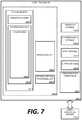
- FIG. 7is a block diagram illustrating physical components (i.e., hardware) of a computing device 1800 with which embodiments of the disclosure may be practiced.
- the computing device components described belowmay be suitable to act as the computing devices described above, such as wireless computing device and/or medical device of FIG. 1 .
- the computing device 1800may include at least one processing unit 1802 and a system memory 1804 .
- the system memory 1804may comprise, but is not limited to, volatile storage (e.g., random access memory), non-volatile storage (e.g., read-only memory), flash memory, or any combination of such memories.
- the system memory 1804may include an operating system 1805 and one or more program modules 1806 suitable for running software applications 1820 .
- the operating system 1805may be suitable for controlling the operation of the computing device 1800 .
- embodiments of the disclosuremay be practiced in conjunction with a graphics library, other operating systems, or any other application program and is not limited to any particular application or system.
- This basic configurationis illustrated in FIG. 7 by those components within a dashed line 1808 .
- the computing device 1800may have additional features or functionality.
- the computing device 1800may also include additional data storage devices (removable and/or non-removable) such as, for example, magnetic disks, optical disks, or tape. Such additional storage is illustrated in FIG. 7 by a removable storage device 1809 and a non-removable storage device 1810 .
- a number of program modules and data filesmay be stored in the system memory 1804 . While executing on the processing unit 1802 , the program modules 1806 may perform processes including, but not limited to, generate list of devices, broadcast user-friendly name, broadcast transmitter power, determine proximity of wireless computing device, connect with wireless computing device, transfer vital sign data to a patient's EMR, sort list of wireless computing devices within range, and other processes described with reference to the figures as described herein.
- Other program modulesthat may be used in accordance with embodiments of the present disclosure, and in particular to generate screen content, may include electronic mail and contacts applications, word processing applications, spreadsheet applications, database applications, slide presentation applications, drawing or computer-aided application programs, etc.
- embodiments of the disclosuremay be practiced in an electrical circuit comprising discrete electronic elements, packaged or integrated electronic chips containing logic gates, a circuit utilizing a microprocessor, or on a single chip containing electronic elements or microprocessors.
- embodiments of the disclosuremay be practiced via a system-on-a-chip (SOC) where each or many of the components illustrated in FIG. 7 may be integrated onto a single integrated circuit.
- SOCsystem-on-a-chip
- Such an SOC devicemay include one or more processing units, graphics units, communications units, system virtualization units and various application functionality all of which are integrated (or “burned”) onto the chip substrate as a single integrated circuit.
- the functionality, described herein,may be operated via application-specific logic integrated with other components of the computing device 1800 on the single integrated circuit (chip).
- Embodiments of the disclosuremay also be practiced using other technologies capable of performing logical operations such as, for example, AND, OR, and NOT, including but not limited to mechanical, optical, fluidic, and quantum technologies.
- embodiments of the disclosuremay be practiced within a general purpose computer or in any other circuits or systems.
- the computing device 1800may also have one or more input device(s) 1812 such as a keyboard, a mouse, a pen, a sound or voice input device, a touch or swipe input device, etc.
- the output device(s) 1814such as a display, speakers, a printer, etc. may also be included.
- the aforementioned devicesare examples and others may be used.
- the computing device 1800may include one or more communication connections 1816 allowing communications with other computing devices. Examples of suitable communication connections 1816 include, but are not limited to, RF transmitter, receiver, and/or transceiver circuitry; universal serial bus (USB), parallel, and/or serial ports.
- Computer readable mediamay include non-transitory computer storage media.
- Computer storage mediamay include volatile and nonvolatile, removable and non-removable media implemented in any method or technology for storage of information, such as computer readable instructions, data structures, or program modules.
- the system memory 1804 , the removable storage device 1809 , and the non-removable storage device 1810are all computer storage media examples (i.e., memory storage.)
- Computer storage mediamay include RAM, ROM, electrically erasable read-only memory (EEPROM), flash memory or other memory technology, CD-ROM, digital versatile disks (DVD) or other optical storage, magnetic cassettes, magnetic tape, magnetic disk storage or other magnetic storage devices, or any other article of manufacture which can be used to store information and which can be accessed by the computing device 1800 . Any such computer storage media may be part of the computing device 1800 .
- Computer storage mediadoes not include a carrier wave or other propagated or modulated data signal.
- Communication mediamay be embodied by computer readable instructions, data structures, program modules, or other data in a modulated data signal, such as a carrier wave or other transport mechanism, and includes any information delivery media.
- modulated data signalmay describe a signal that has one or more characteristics set or changed in such a manner as to encode information in the signal.
- communication mediamay include wired media such as a wired network or direct-wired connection, and wireless media such as acoustic, radio frequency (RF), infrared, and other wireless media.
- RFradio frequency
- the example medical devices described hereinare devices used to monitor patients, other types of medical devices can also be used.
- the different components of the CONNEXTM systemsuch as the intermediary servers that communication with the monitoring devices, can also require maintenance in the form of firmware and software updates.
- These intermediary serverscan be managed by the systems and methods described herein to update the maintenance requirements of the servers.
- Embodiments of the present inventionmay be utilized in various distributed computing environments where tasks are performed by remote processing devices that are linked through a communications network in a distributed computing environment.
Landscapes
- Health & Medical Sciences (AREA)
- Life Sciences & Earth Sciences (AREA)
- Engineering & Computer Science (AREA)
- Medical Informatics (AREA)
- Surgery (AREA)
- Biophysics (AREA)
- Biomedical Technology (AREA)
- Heart & Thoracic Surgery (AREA)
- Physics & Mathematics (AREA)
- Molecular Biology (AREA)
- Ophthalmology & Optometry (AREA)
- Animal Behavior & Ethology (AREA)
- General Health & Medical Sciences (AREA)
- Public Health (AREA)
- Veterinary Medicine (AREA)
- Signal Processing (AREA)
- Eye Examination Apparatus (AREA)
Abstract
Description
Claims (10)
Priority Applications (7)
| Application Number | Priority Date | Filing Date | Title |
|---|---|---|---|
| US14/633,601US11045088B2 (en) | 2015-02-27 | 2015-02-27 | Through focus retinal image capturing |
| MA041610AMA41610A (en) | 2015-02-27 | 2016-01-28 | THROUGH-FOCUS RETINAL IMAGE CAPTURE |
| PCT/US2016/015653WO2016137662A1 (en) | 2015-02-27 | 2016-01-29 | Through focus retinal image capturing |
| AU2016223209AAU2016223209B2 (en) | 2015-02-27 | 2016-01-29 | Through focus retinal image capturing |
| CN201680024426.8ACN107534721B (en) | 2015-02-27 | 2016-01-29 | Defocused retinal image capture system |
| EP16756033.3AEP3261518B1 (en) | 2015-02-27 | 2016-01-29 | Through focus retinal image capturing |
| US15/651,853US10799115B2 (en) | 2015-02-27 | 2017-07-17 | Through focus retinal image capturing |
Applications Claiming Priority (1)
| Application Number | Priority Date | Filing Date | Title |
|---|---|---|---|
| US14/633,601US11045088B2 (en) | 2015-02-27 | 2015-02-27 | Through focus retinal image capturing |
Related Child Applications (1)
| Application Number | Title | Priority Date | Filing Date |
|---|---|---|---|
| US15/651,853Continuation-In-PartUS10799115B2 (en) | 2015-02-27 | 2017-07-17 | Through focus retinal image capturing |
Publications (2)
| Publication Number | Publication Date |
|---|---|
| US20160249804A1 US20160249804A1 (en) | 2016-09-01 |
| US11045088B2true US11045088B2 (en) | 2021-06-29 |
Family
ID=56789684
Family Applications (1)
| Application Number | Title | Priority Date | Filing Date |
|---|---|---|---|
| US14/633,601ActiveUS11045088B2 (en) | 2015-02-27 | 2015-02-27 | Through focus retinal image capturing |
Country Status (6)
| Country | Link |
|---|---|
| US (1) | US11045088B2 (en) |
| EP (1) | EP3261518B1 (en) |
| CN (1) | CN107534721B (en) |
| AU (1) | AU2016223209B2 (en) |
| MA (1) | MA41610A (en) |
| WO (1) | WO2016137662A1 (en) |
Families Citing this family (21)
| Publication number | Priority date | Publication date | Assignee | Title |
|---|---|---|---|---|
| US9237847B2 (en) | 2014-02-11 | 2016-01-19 | Welch Allyn, Inc. | Ophthalmoscope device |
| US9211064B2 (en) | 2014-02-11 | 2015-12-15 | Welch Allyn, Inc. | Fundus imaging system |
| US10799115B2 (en) | 2015-02-27 | 2020-10-13 | Welch Allyn, Inc. | Through focus retinal image capturing |
| US10136804B2 (en) | 2015-07-24 | 2018-11-27 | Welch Allyn, Inc. | Automatic fundus image capture system |
| US10772495B2 (en) | 2015-11-02 | 2020-09-15 | Welch Allyn, Inc. | Retinal image capturing |
| WO2017120217A1 (en) | 2016-01-07 | 2017-07-13 | Welch Allyn, Inc. | Infrared fundus imaging system |
| US10835120B2 (en) | 2016-08-23 | 2020-11-17 | Welch Allyn, Inc. | Extended medical test system |
| US10602926B2 (en) | 2016-09-29 | 2020-03-31 | Welch Allyn, Inc. | Through focus retinal image capturing |
| US10285589B2 (en) | 2016-09-30 | 2019-05-14 | Welch Allyn, Inc. | Fundus image capture system |
| USD881938S1 (en) | 2017-05-18 | 2020-04-21 | Welch Allyn, Inc. | Electronic display screen of a medical device with an icon |
| US10726547B2 (en)* | 2017-05-18 | 2020-07-28 | Welch Allyn, Inc. | Fundus image capturing |
| AU2018304105B2 (en)* | 2017-07-17 | 2020-11-19 | Welch Allyn, Inc. | Through focus retinal image capturing |
| US10520393B2 (en) | 2017-08-10 | 2019-12-31 | Bae Systems Information And Electronic Systems Integration Inc. | System and method for verifying a diopter setting and range of an optical system eyepiece |
| US11160449B2 (en) | 2017-08-29 | 2021-11-02 | Verily Life Sciences Llc | Focus stacking for retinal imaging |
| KR101990376B1 (en)* | 2017-09-27 | 2019-06-20 | 주식회사 이루다 | Fundus camera |
| US11730356B2 (en) | 2017-11-06 | 2023-08-22 | Vision Products, Llc | Mobile ophthalmic device |
| US11096574B2 (en) | 2018-05-24 | 2021-08-24 | Welch Allyn, Inc. | Retinal image capturing |
| CN120458494A (en)* | 2018-10-13 | 2025-08-12 | 普瑞文塔医疗公司 | Illuminated contact lenses and systems for improved ocular diagnostics, disease management, and surgery |
| US20230072066A1 (en)* | 2019-11-25 | 2023-03-09 | Optos Plc | Choroidal Imaging |
| US20210386289A1 (en)* | 2020-06-12 | 2021-12-16 | Optotune Ag | Camera and method for operating a camera |
| CN113133740A (en)* | 2021-05-21 | 2021-07-20 | 苏州依视禾医疗科技有限公司 | Large-depth-of-field eye imaging equipment |
Citations (211)
| Publication number | Priority date | Publication date | Assignee | Title |
|---|---|---|---|---|
| US5048946A (en) | 1990-05-15 | 1991-09-17 | Phoenix Laser Systems, Inc. | Spectral division of reflected light in complex optical diagnostic and therapeutic systems |
| US5557350A (en) | 1994-04-15 | 1996-09-17 | Nidek Co. Ltd. | Ophthalmometric apparatus with alignment device including filter means |
| US5599276A (en) | 1996-02-13 | 1997-02-04 | Welch Allyn, Inc. | Diopter value viewing means for a video ophthalmoscope |
| US5703621A (en) | 1994-04-28 | 1997-12-30 | Xerox Corporation | Universal display that presents all image types with high image fidelity |
| US5713047A (en) | 1992-06-08 | 1998-01-27 | Canon Kabushiki Kaisha | Eye fundus photographing apparatus |
| US5776060A (en) | 1997-02-20 | 1998-07-07 | University Of Alabama In Huntsville | Method and apparatus for measuring blood oxygen saturation within a retinal vessel with light having several selected wavelengths |
| US5784148A (en) | 1996-04-09 | 1998-07-21 | Heacock; Gregory Lee | Wide field of view scanning laser ophthalmoscope |
| US5943116A (en) | 1997-04-01 | 1999-08-24 | Johns Hopkins University | System for imaging an ocular fundus semi-automatically at high resolution and wide field |
| US6000799A (en) | 1998-05-01 | 1999-12-14 | Jozef F. Van De Velde | Maxwellian view and modulation control options for the scanning laser ophthalmoscope |
| US6011585A (en) | 1996-01-19 | 2000-01-04 | Apple Computer, Inc. | Apparatus and method for rotating the display orientation of a captured image |
| US6120461A (en) | 1999-08-09 | 2000-09-19 | The United States Of America As Represented By The Secretary Of The Army | Apparatus for tracking the human eye with a retinal scanning display, and method thereof |
| US6296358B1 (en)* | 2000-07-14 | 2001-10-02 | Visual Pathways, Inc. | Ocular fundus auto imager |
| US6301440B1 (en) | 2000-04-13 | 2001-10-09 | International Business Machines Corp. | System and method for automatically setting image acquisition controls |
| US6307526B1 (en) | 1998-02-02 | 2001-10-23 | W. Steve G. Mann | Wearable camera system with viewfinder means |
| US6309070B1 (en) | 2000-09-06 | 2001-10-30 | Medibell Medical Vision Technologies, Ltd. | Integrated ophthalmic illumination method and system |
| US6325511B1 (en) | 1999-01-28 | 2001-12-04 | Kowa Company Ltd. | Ophthalmic photographic apparatus |
| US6350031B1 (en) | 1996-07-29 | 2002-02-26 | Kameran Lashkari | Electro-optic binocular indirect ophthalmoscope |
| US20020052551A1 (en) | 2000-08-23 | 2002-05-02 | Sinclair Stephen H. | Systems and methods for tele-ophthalmology |
| US20020101568A1 (en) | 2001-01-30 | 2002-08-01 | Eberl Heinrich A. | Interactive data view and command system |
| US20030009155A1 (en) | 2000-05-12 | 2003-01-09 | Ceramoptec Industries, Inc. | Method for accurate optical treatment of an eye's fundus |
| GB2378600A (en) | 2001-08-06 | 2003-02-12 | Patrick Kerr | Retinal function camera to determine retinal blood oxygenation. |
| US20030071970A1 (en) | 2001-10-17 | 2003-04-17 | Carl Zeiss Meditec Ag | Ophthalmologic examination instrument |
| US6556853B1 (en) | 1995-12-12 | 2003-04-29 | Applied Spectral Imaging Ltd. | Spectral bio-imaging of the eye |
| US20030163031A1 (en)* | 2000-06-26 | 2003-08-28 | Adlabs, Inc. | Method and system for providing centralized anatomic pathology services |
| US20030208125A1 (en) | 2002-04-09 | 2003-11-06 | Rodney Dennis Watkins | Fundus Camera |
| US6666857B2 (en) | 2002-01-29 | 2003-12-23 | Robert F. Smith | Integrated wavefront-directed topography-controlled photoablation |
| WO2004089214A2 (en) | 2003-04-11 | 2004-10-21 | Bausch & Lomb Inc. | System and method for acquiring data and aligning and tracking of an eye |
| US20040258285A1 (en) | 2001-10-03 | 2004-12-23 | Hansen Johan Dore | Assessment of lesions in an image |
| US20050012899A1 (en)* | 2002-06-14 | 2005-01-20 | Physical Sciences, Inc. | Line-scan laser ophthalmoscope |
| US20050043588A1 (en) | 1998-11-25 | 2005-02-24 | Jory Tsai | Medical inspection device |
| US20050110949A1 (en) | 2003-10-28 | 2005-05-26 | Welch Allyn, Inc. | Digital documenting ophthalmoscope |
| US20050254008A1 (en) | 2002-06-14 | 2005-11-17 | Ferguson R D | Monitoring blood flow in the retina using a line-scanning laser ophthalmoscope |
| CN1704017A (en) | 2004-05-29 | 2005-12-07 | 倪蔚民 | Real time automatic non-invasion iris optical imaging device |
| WO2006016366A2 (en) | 2004-08-12 | 2006-02-16 | Elop Electro-Optical Industries Ltd. | Integrated retinal imager and method |
| JP2006101943A (en) | 2004-09-30 | 2006-04-20 | Nidek Co Ltd | Fundus camera |
| US20060113386A1 (en) | 2004-12-01 | 2006-06-01 | Psc Scanning, Inc. | Illumination pulsing method for a data reader |
| US20060119858A1 (en) | 2004-12-02 | 2006-06-08 | Knighton Robert W | Enhanced optical coherence tomography for anatomical mapping |
| US20060147095A1 (en) | 2005-01-03 | 2006-07-06 | Usher David B | Method and system for automatically capturing an image of a retina |
| US20060159367A1 (en) | 2005-01-18 | 2006-07-20 | Trestle Corporation | System and method for creating variable quality images of a slide |
| US20060202038A1 (en) | 2005-03-11 | 2006-09-14 | Ynjiun Wang | System and method to automatically focus an image reader |
| US20060202036A1 (en) | 2005-03-11 | 2006-09-14 | Ynjiun Wang | Bar code reading device with global electronic shutter control |
| US7134754B2 (en) | 2001-04-09 | 2006-11-14 | Patrick Kerr | Retinal function camera |
| US20060268231A1 (en) | 2003-07-03 | 2006-11-30 | Medibell Medicall Vision Technologies, Ltd. | Illumination method and system for obtaining color images by transcleral ophthalmic illumination |
| US20070030450A1 (en) | 2005-08-03 | 2007-02-08 | Eastman Kodak Company | Automated fundus imaging system |
| US20070174152A1 (en) | 2003-12-08 | 2007-07-26 | Bjornberg David B | Handheld system for information acquisition, verification, recording, processing, display and communication |
| US20070188706A1 (en) | 2006-01-27 | 2007-08-16 | Pearson Ken J | Fundus image display system |
| US7264355B2 (en) | 2002-12-16 | 2007-09-04 | Sis Ag Surgical Instrument Systems | Ophthalmologic device and ophthalmologic measuring method |
| US7311400B2 (en) | 2001-04-16 | 2007-12-25 | Tracey Technologies, Llc | Determining clinical refraction of eye |
| US20080084538A1 (en)* | 2006-10-04 | 2008-04-10 | Naoyuki Maeda | Fundus oculi observation device, a fundus oculi image display device and a fundus oculi image display method |
| US7377643B1 (en) | 2004-08-13 | 2008-05-27 | Q Step Technologies, Inc. | Method and apparatus for eye imaging with position registration and constant pupil size |
| US7380938B2 (en) | 2003-03-25 | 2008-06-03 | Sarnoff Corporation | Apparatus to detect and measure saccade and pupilary changes |
| US7387384B2 (en) | 2005-05-02 | 2008-06-17 | Heine Optotechnik Gmbh & Co. Kg | Ophthalmoscope |
| US20080165322A1 (en) | 2007-01-10 | 2008-07-10 | Clarity Medical Systems, Inc. | Working distance and alignment sensor for a fundus camera |
| WO2008106802A1 (en) | 2007-03-08 | 2008-09-12 | University Of Northern British Columbia | Apparatus and method for objective perimetry visual field test |
| US20080231803A1 (en) | 2006-09-28 | 2008-09-25 | University Of Rochester | Compact ocular fundus camera |
| US20080316426A1 (en) | 2007-06-04 | 2008-12-25 | Nidek Co. Ltd. | Fundus camera |
| US7470024B2 (en) | 2006-06-12 | 2008-12-30 | Opto Eletronics S/A | System for obtaining a fundus image |
| US7488294B2 (en) | 2004-04-01 | 2009-02-10 | Torch William C | Biosensors, communicators, and controllers monitoring eye movement and methods for using them |
| US7502639B2 (en) | 2004-06-29 | 2009-03-10 | Patrick Kerr | Analysis of retinal metabolism over at least a portion of a cardiac cycle |
| US20090096885A1 (en) | 2007-10-08 | 2009-04-16 | Keymed (Medical & Industrial Equipment) Ltd | Electronic Camera |
| JP2009172157A (en) | 2008-01-24 | 2009-08-06 | Topcon Corp | Ophthalmological photographing apparatus |
| US20090225277A1 (en) | 2008-03-05 | 2009-09-10 | Tamir Gil | Snapshot Spectral Imaging of the Eye |
| JP2009219644A (en) | 2008-03-14 | 2009-10-01 | Nidek Co Ltd | Scanning fundus imaging apparatus |
| US20090275929A1 (en) | 2008-04-30 | 2009-11-05 | Amo Development, Llc | System and method for controlling measurement in an eye during ophthalmic procedure |
| US20090316115A1 (en) | 2008-03-28 | 2009-12-24 | Tatsuo Itoh | Image display apparatus and image display method |
| US20090323023A1 (en) | 2005-03-31 | 2009-12-31 | Kabushiki Kaisha Topcon | Ophthalmologic Imager |
| US20090323022A1 (en) | 2008-06-26 | 2009-12-31 | Canon Kabushiki Kaisha | Medical imaging apparatus |
| US20100007849A1 (en) | 2006-07-07 | 2010-01-14 | Od-Os Gmbh | Ophthalmoscope |
| US20100007848A1 (en) | 2008-07-04 | 2010-01-14 | Nidek Co., Ltd. | Optical tomographic image photographing apparatus |
| US20100014052A1 (en) | 2006-12-21 | 2010-01-21 | Ingo Koschmieder | Optical system for a fundus camera |
| JP2010057547A (en) | 2008-09-01 | 2010-03-18 | Canon Inc | Fundus camera |
| US20100085538A1 (en) | 2008-09-25 | 2010-04-08 | Canon Kabushiki Kaisha | Eye fundus camera |
| US20100110375A1 (en) | 2007-04-18 | 2010-05-06 | Kabushiki Kaisha Topcon | Optical image measurement device |
| US20100149489A1 (en) | 2007-05-23 | 2010-06-17 | Kabushiki Kaisha Topcon | Fundus oculi observation device and program for controlling the same |
| WO2010080576A1 (en) | 2008-12-19 | 2010-07-15 | University Of Miami | System and method for early detection of diabetic retinopathy using optical coherence tomography |
| US20100208961A1 (en) | 2006-12-11 | 2010-08-19 | Cytyc Corporation | Method for assessing image focus quality |
| US7784940B2 (en) | 1998-11-24 | 2010-08-31 | Welch Allyn, Inc. | Eye viewing device comprising video capture optics |
| US20100238402A1 (en) | 2009-03-19 | 2010-09-23 | Canon Kabushiki Kaisha | Fundus camera |
| US7809160B2 (en) | 2003-11-14 | 2010-10-05 | Queen's University At Kingston | Method and apparatus for calibration-free eye tracking using multiple glints or surface reflections |
| WO2010115195A1 (en) | 2009-04-03 | 2010-10-07 | Dyer Holdings, Llc | Infrared slit lamp ophthalmoscope |
| US20110001927A1 (en) | 2008-02-01 | 2011-01-06 | Linos Photonics Gmbh & Co., Kg | Fundus scanning apparatus |
| US7871164B2 (en) | 2006-02-28 | 2011-01-18 | Carl Zeiss Meditec Ag | Ophthalmological instrument |
| US20110028513A1 (en)* | 2008-03-31 | 2011-02-03 | Lang Zhuo | Method for treating neurological disorders with imidazolium and imidazolinium compounds |
| US20110043756A1 (en) | 2008-04-22 | 2011-02-24 | Annidis Health Systems Corp. | Retinal fundus surveillance method and apparatus |
| WO2011029064A1 (en) | 2009-09-04 | 2011-03-10 | University Of Virginia Patent Foundation | Hand-held portable fundus camera for screening photography |
| US7926945B2 (en) | 2005-07-22 | 2011-04-19 | Carl Zeiss Meditec Ag | Device and method for monitoring, documenting and/or diagnosing the fundus |
| JP2011097992A (en) | 2009-11-04 | 2011-05-19 | Canon Inc | Fundus observation apparatus, fundus observation method, and computer program |
| US7963653B1 (en) | 2009-07-29 | 2011-06-21 | Eyequick, Llc | Digital imaging ophthalmoscope |
| US7976162B2 (en) | 2006-09-29 | 2011-07-12 | Daniel Ian Flitcroft | Eye examining system and method |
| US20110169935A1 (en) | 2008-10-15 | 2011-07-14 | Optibrand Ltd., Llc | Method and apparatus for obtaining an image of an ocular feature |
| US20110234977A1 (en)* | 2010-03-23 | 2011-09-29 | Steven Roger Verdooner | Apparatus and method for imaging an eye |
| US20110242306A1 (en) | 2008-12-19 | 2011-10-06 | The Johns Hopkins University | System and method for automated detection of age related macular degeneration and other retinal abnormalities |
| EP2374404A1 (en) | 2009-01-06 | 2011-10-12 | Kabushiki Kaisha TOPCON | Optical image measurement device and method for controlling same |
| US20110261184A1 (en) | 2008-10-17 | 2011-10-27 | Mason Michael S | Optical microscope methods and apparatuses |
| US20110299034A1 (en) | 2008-07-18 | 2011-12-08 | Doheny Eye Institute | Optical coherence tomography- based ophthalmic testing methods, devices and systems |
| US20110299036A1 (en) | 2010-06-02 | 2011-12-08 | Goldenholz Daniel M | Portable digital direct ophthalmoscope |
| US20120002167A1 (en) | 2010-07-05 | 2012-01-05 | Nidek Co., Ltd. | Ophthalmic apparatus |
| CN102324014A (en) | 2005-03-11 | 2012-01-18 | 手持产品公司 | Bar code reading device with global electronic shutter control |
| WO2012009702A1 (en) | 2010-07-15 | 2012-01-19 | Corinthian Ophthalmic, Inc. | Method and system for performing remote treatment and monitoring |
| US20120033227A1 (en)* | 2010-08-05 | 2012-02-09 | Bower Bradley A | Compact Multimodality Optical Coherence Tomography Imaging Systems and Related Methods and Computer Program Products |
| US20120044456A1 (en) | 2009-04-30 | 2012-02-23 | Kabushiki Kaisha Topcon | Fundus observation apparatus |
| US20120050677A1 (en) | 2010-08-31 | 2012-03-01 | Canon Kabushiki Kaisha | Fundus imaging apparatus |
| US20120121158A1 (en) | 2009-07-29 | 2012-05-17 | Kabushiki Kaisha Topcon | Ophthalmic observation apparatus |
| US20120147327A1 (en) | 2009-08-27 | 2012-06-14 | Canon Kabushiki Kaisha | Ophthalmologic photographing apparatus and camera for use in ophthalmologic photographing |
| US20120169995A1 (en) | 2010-09-14 | 2012-07-05 | Carl Zeiss Meditec Ag | Method and device for producing high-quality fundus images |
| CN102626304A (en) | 2012-04-19 | 2012-08-08 | 重庆大学 | Head-mounted wireless video eye tracker |
| US20120200690A1 (en) | 2009-10-05 | 2012-08-09 | Keeler Limited | Ophthalmic instruments |
| US20120213423A1 (en)* | 2009-05-29 | 2012-08-23 | University Of Pittsburgh -- Of The Commonwealth System Of Higher Education | Blood vessel segmentation with three dimensional spectral domain optical coherence tomography |
| US20120218301A1 (en) | 2010-02-28 | 2012-08-30 | Osterhout Group, Inc. | See-through display with an optical assembly including a wedge-shaped illumination system |
| US20120229764A1 (en) | 2011-03-10 | 2012-09-13 | Canon Kabushiki Kaisha | Ophthalmologic apparatus and control method of the same |
| US20120248196A1 (en) | 2005-06-03 | 2012-10-04 | Hand Held Products, Inc. | Apparatus having hybrid monochrome and color image sensor array |
| WO2012134272A1 (en) | 2011-03-25 | 2012-10-04 | L2G B.V. | Multifunctional apparatus and method for inspecting an eye |
| US20120249956A1 (en) | 2011-03-30 | 2012-10-04 | Carl Zeiss Meditec, Inc. | Systems and methods for efficiently obtaining measurements of the human eye using tracking |
| US20120257163A1 (en) | 2008-10-28 | 2012-10-11 | Dyer Holdings, Llc | Video Infrared Ophthalmoscope |
| US20120281874A1 (en) | 2011-05-05 | 2012-11-08 | Lure Yuan-Ming F | Method, material, and apparatus to improve acquisition of human frontal face images using image template |
| JP2012213575A (en) | 2011-04-01 | 2012-11-08 | Canon Inc | Ophthalmologic photographing apparatus |
| US20120287255A1 (en) | 2009-12-04 | 2012-11-15 | Lumetrics, Inc. | Portable fundus camera |
| US20120320340A1 (en) | 2011-06-18 | 2012-12-20 | Intuitive Medical Technologies, Llc | Smart-phone adapter for ophthalmoscope |
| US8347106B2 (en) | 2007-07-03 | 2013-01-01 | Nds Limited | Method and apparatus for user authentication based on a user eye characteristic |
| US20130002711A1 (en) | 2010-03-31 | 2013-01-03 | Canon Kabushiki Kaisha | Image processing apparatus, oct imaging apparatus, tomographic imaging system, control method, and program |
| US20130010260A1 (en) | 2011-07-08 | 2013-01-10 | Carl Zeiss Meditec, Inc. | Light field camera for fundus photography |
| US20130016320A1 (en) | 2011-07-14 | 2013-01-17 | Canon Kabushiki Kaisha | Imaging control apparatus, ophthalmic imaging apparatus, imaging control method, and program |
| US20130028484A1 (en) | 2011-07-29 | 2013-01-31 | Canon Kabushiki Kaisha | Image processing apparatus for fundus image, image processing method for fundus image, and program medium |
| US8366270B2 (en) | 2008-04-30 | 2013-02-05 | Universitat Politecnica De Catalunya | Method and system for the objective measurement of ocular accommodation |
| US20130033593A1 (en) | 2009-10-14 | 2013-02-07 | Chinnock Randal B | Portable Retinal Camera and Image Acquisition Method |
| US8388523B2 (en) | 2005-04-01 | 2013-03-05 | Welch Allyn, Inc. | Medical diagnostic instrument having portable illuminator |
| US20130057828A1 (en) | 2009-08-31 | 2013-03-07 | Marc De Smet | Handheld portable fundus imaging system and method |
| JP2013046850A (en) | 2012-12-04 | 2013-03-07 | Canon Inc | Fundus camera |
| US20130063698A1 (en) | 2011-09-14 | 2013-03-14 | Kabushiki Kaisha Topcon | Fundus observation apparatus |
| WO2013041658A1 (en) | 2011-09-23 | 2013-03-28 | Carl Zeiss Ag | Appliance and method for recording an image of an ocular fundus |
| US20130128223A1 (en) | 2011-11-09 | 2013-05-23 | Wetch Allyn, Inc. | Digital-based medical devices |
| WO2013082387A1 (en) | 2011-12-02 | 2013-06-06 | Aguren Jerry G | Wide field-of-view 3d stereo vision platform with dynamic control of immersive or heads-up display operation |
| US20130162950A1 (en) | 2011-12-21 | 2013-06-27 | Canon Kabushiki Kaisha | Ophthalmologic apparatus and ophthalmologic control method, and program |
| US20130169934A1 (en) | 2011-12-09 | 2013-07-04 | Steven Roger Verdooner | Method for combining a plurality of eye images into a plenoptic multifocal image |
| US20130176533A1 (en) | 2012-01-06 | 2013-07-11 | Hayes Solos Raffle | Structured Light for Eye-Tracking |
| US8488895B2 (en) | 2006-05-31 | 2013-07-16 | Indiana University Research And Technology Corp. | Laser scanning digital camera with pupil periphery illumination and potential for multiply scattered light imaging |
| WO2013107464A1 (en) | 2012-01-19 | 2013-07-25 | Daif Mohammad Abdelfattah | Corneal visual center localizer (or locator) |
| US20130194548A1 (en) | 2011-04-07 | 2013-08-01 | Raytheon Company | Portable retinal imaging device |
| US20130201449A1 (en)* | 2008-03-27 | 2013-08-08 | Doheny Eye Institute | Optical coherence tomography device, method, and system |
| US20130211285A1 (en) | 2011-12-02 | 2013-08-15 | Terry A. Fuller | Devices and Methods for Noninvasive Measurement of Intracranial Pressure |
| US20130208241A1 (en) | 2012-02-13 | 2013-08-15 | Matthew Everett Lawson | Methods and Apparatus for Retinal Imaging |
| US20130215387A1 (en) | 2012-02-21 | 2013-08-22 | Canon Kabushiki Kaisha | Fundus imaging apparatus and method |
| US20130222763A1 (en) | 2010-11-06 | 2013-08-29 | Carl Zeiss Meditec Ag | Fundus camera with strip-shaped pupil division, and method for recording artifact-free, high-resolution fundus images |
| US20130229622A1 (en) | 2012-03-02 | 2013-09-05 | Nidek Co., Ltd. | Ophthalmologic photographing apparatus and ophthalmologic photographing method |
| US20130234930A1 (en) | 2012-03-07 | 2013-09-12 | Julian Palacios Goerger | Scanning mirror laser and projector head-up display glasses |
| US8534837B2 (en) | 2009-05-01 | 2013-09-17 | Bioptigen, Inc. | Systems for imaging structures of a subject and related methods |
| US20130250237A1 (en) | 2005-10-31 | 2013-09-26 | Nidek Co., Ltd. | Ophthalmic photographing apparatus |
| US20130250242A1 (en)* | 2012-03-21 | 2013-09-26 | Optovue, Inc. | Fundus camera |
| US8577644B1 (en) | 2013-03-11 | 2013-11-05 | Cypress Semiconductor Corp. | Hard press rejection |
| US20130301004A1 (en) | 2008-04-22 | 2013-11-14 | Annidis Health Systems Corp. | Retinal fundus surveillance method and apparatus |
| US8585203B2 (en) | 2009-05-22 | 2013-11-19 | Canon Kabushiki Kaisha | Ophthalmologic photographing apparatus |
| US8620048B2 (en) | 2010-03-19 | 2013-12-31 | Canon Kabushiki Kaisha | Image processing apparatus, image processing system, image processing method, and image processing computer program |
| US20140022270A1 (en) | 2012-07-18 | 2014-01-23 | Optos Public Limited Company | Alignment Apparatus |
| US8649008B2 (en) | 2010-02-04 | 2014-02-11 | University Of Southern California | Combined spectral and polarimetry imaging and diagnostics |
| US20140055745A1 (en) | 2012-08-27 | 2014-02-27 | Canon Kabushiki Kaisha | Image processing apparatus and image processing method |
| US8696122B2 (en) | 2010-01-21 | 2014-04-15 | Physical Sciences, Inc. | Multi-functional adaptive optics retinal imaging |
| US20140104573A1 (en) | 2010-06-01 | 2014-04-17 | Canon Kabshiki Kaisha | Ophthalmic imaging apparatus and control method thereof |
| US20140111773A1 (en) | 2012-10-18 | 2014-04-24 | Canon Kabushiki Kaisha | Ophthalmologic apparatus, ophthalmologic control method, and program |
| US20140118697A1 (en) | 2012-10-26 | 2014-05-01 | Canon Kabushiki Kaisha | Ophthalmologic apparatus and method for controlling the same |
| US20140118693A1 (en) | 2012-10-26 | 2014-05-01 | Canon Kabushiki Kaisha | Ophthalmologic apparatus, control method thereof, and program |
| US20140132926A1 (en) | 2012-11-09 | 2014-05-15 | Canon Kabushiki Kaisha | Ophthalmic imaging apparatus, control method for ophtalmic imaging apparatus, and storage medium |
| US20140180081A1 (en) | 2010-10-25 | 2014-06-26 | Steven Roger Verdooner | Apparatus and Method For Detecting Amyloid In A Retina in a Diagnosis, Advancement, and Prognosing Of Alzheimer's disease, traumatic brain injury, macular degeneration and a plurality of Neurodegenerative dissorders, and Ocular Diseases |
| US20140192320A1 (en) | 2013-01-08 | 2014-07-10 | Altek Corporation | Image capturing apparatus and capturing method |
| US20140198298A1 (en) | 2013-01-14 | 2014-07-17 | Altek Corporation | Image stitching method and camera system |
| US20140204341A1 (en) | 2013-01-23 | 2014-07-24 | Nidek Co., Ltd. | Ophthalmic imaging apparatus |
| US20140211162A1 (en) | 2013-01-31 | 2014-07-31 | Canon Kabushiki Kaisha | Ophthalmologic apparatus and method for controlling the same |
| US20140268046A1 (en) | 2013-03-14 | 2014-09-18 | Carl Zeiss Meditec, Inc. | Systems and methods for improved acquisition of ophthalmic optical coherence tomography data |
| US20140267668A1 (en)* | 2013-03-15 | 2014-09-18 | Lumetrics, Inc. | Portable fundus camera |
| US20140307228A1 (en) | 2013-04-12 | 2014-10-16 | Canon Kabushiki Kaisha | Ophthalmologic apparatus, method for controlling ophthalmologic apparatus, and program |
| US8879813B1 (en) | 2013-10-22 | 2014-11-04 | Eyenuk, Inc. | Systems and methods for automated interest region detection in retinal images |
| US20140330352A1 (en) | 2012-05-25 | 2014-11-06 | Ojai Retinal Technology, Llc | Apparatus for retina phototherapy |
| WO2014182769A1 (en) | 2013-05-07 | 2014-11-13 | The Johns Hopkins University | Automated and non-mydriatic fundus-perimetry camera for irreversible eye diseases |
| US20150002811A1 (en) | 2013-06-28 | 2015-01-01 | Canon Kabushiki Kaisha | Image processing apparatus and image processing method |
| US20150009357A1 (en) | 2012-02-16 | 2015-01-08 | University Of Washington Through Its Center For Commercialization | Extended depth of focus for high-resolution optical image scanning |
| US20150021228A1 (en) | 2012-02-02 | 2015-01-22 | Visunex Medical Systems Co., Ltd. | Eye imaging apparatus and systems |
| WO2015044366A1 (en) | 2013-09-30 | 2015-04-02 | Carl Zeiss Meditec Ag | High temporal resolution doppler oct imaging of retinal blood flow |
| US20150150449A1 (en)* | 2013-11-29 | 2015-06-04 | Canon Kabushiki Kaisha | Ophthalmologic apparatus and method of controlling the same |
| US20150170360A1 (en)* | 2013-12-18 | 2015-06-18 | Canon Kabushiki Kaisha | Ophthalmic reference image selection |
| US20150178946A1 (en) | 2013-12-19 | 2015-06-25 | Google Inc. | Image adjustment using texture mask |
| WO2015100294A1 (en) | 2013-12-23 | 2015-07-02 | Optibrand Ltd., Llc | Wide field retinal image capture system and method |
| US20150272434A1 (en) | 2014-03-31 | 2015-10-01 | Nidek Co., Ltd. | Fundus photography device |
| WO2015170947A1 (en) | 2014-05-09 | 2015-11-12 | (주)루트로닉 | Ophthalmic treatment device |
| US20150342459A1 (en) | 2014-05-29 | 2015-12-03 | Kabushiki Kaisha Topcon | Ophthalmologic apparatus |
| US9211064B2 (en) | 2014-02-11 | 2015-12-15 | Welch Allyn, Inc. | Fundus imaging system |
| US20160007845A1 (en) | 2014-07-10 | 2016-01-14 | Canon Kabushiki Kaisha | Fundus imaging apparatus, aberration correction method, and storage medium |
| US9237847B2 (en) | 2014-02-11 | 2016-01-19 | Welch Allyn, Inc. | Ophthalmoscope device |
| CN205006859U (en) | 2015-03-14 | 2016-02-03 | 中国科学院苏州生物医学工程技术研究所 | Two mesh pupils comprehensive testing system of setting a camera |
| CN105433899A (en) | 2015-11-30 | 2016-03-30 | 中国科学院苏州生物医学工程技术研究所 | Pupil detection device |
| US20160092721A1 (en) | 2013-05-19 | 2016-03-31 | Commonwealth Scientific And Industrial Research Organization | A system and method for remote medical diagnosis |
| CN205181314U (en) | 2015-03-14 | 2016-04-27 | 中国科学院苏州生物医学工程技术研究所 | Portable pair of mesh pupil detection device |
| US20160120405A1 (en) | 2014-10-29 | 2016-05-05 | Kabushiki Kaisha Topcon | Ophthalmologic apparatus |
| WO2016070781A1 (en) | 2014-11-03 | 2016-05-12 | 苏州思源科安信息技术有限公司 | Mobile terminal visible light and biometric identification combination opto-electronic imaging system and method |
| US20160135678A1 (en) | 2013-06-10 | 2016-05-19 | Essilor International (Compagnie Generale D'optique) | Method For Determining Wave-Front Aberration Data Of A To-Be-Tested Optical System |
| US20160166141A1 (en) | 2013-07-10 | 2016-06-16 | Commonwealth Scientific And Industrial Research Organisation | Quantifying a blood vessel reflection parameter of the retina |
| US20160188993A1 (en) | 2014-12-30 | 2016-06-30 | Kodak Alaris Inc. | System and method for measuring mobile document image quality |
| US9398851B2 (en) | 2011-06-24 | 2016-07-26 | Remidio Innovative Solutions Pvt. Ltd. | Retinal imaging device |
| US20160213249A1 (en) | 2011-03-02 | 2016-07-28 | Brien Holden Vision Diagnostics | Ocular Fundus Imaging Systems, Devices and Methods |
| US9462945B1 (en) | 2013-04-22 | 2016-10-11 | VisionQuest Biomedical LLC | System and methods for automatic processing of digital retinal images in conjunction with an imaging device |
| US20160307341A1 (en) | 2015-04-15 | 2016-10-20 | Canon Kabushiki Kaisha | Image processing apparatus and method of operation of the same |
| US20170020389A1 (en) | 2015-07-24 | 2017-01-26 | Ynjiun Paul Wang | Automatic fundus image capture system |
| US20170119241A1 (en) | 2015-11-02 | 2017-05-04 | Welch Allyn, Inc. | Retinal image capturing |
| US20170161892A1 (en) | 2014-07-02 | 2017-06-08 | Si14 S.P.A. | A method for acquiring and processing images of an ocular fundus by means of a portable electronic device |
| US20170172675A1 (en) | 2014-03-19 | 2017-06-22 | Intuitive Surgical Operations, Inc. | Medical devices, systems, and methods using eye gaze tracking |
| US20170181625A1 (en) | 2015-12-28 | 2017-06-29 | Canon Kabushiki Kaisha | System and Method for Controlling a Fundus Imaging Apparatus |
| US20170196452A1 (en) | 2016-01-07 | 2017-07-13 | Welch Allyn, Inc. | Infrared Fundus Imaging System |
| US20170209044A1 (en) | 2014-07-18 | 2017-07-27 | Kabushiki Kaisha Topcon | Visual function testing device and visual function testing system |
| US20170316565A1 (en) | 2016-04-29 | 2017-11-02 | Carl Zeiss Meditec, Inc. | Montaging of wide-field fundus images |
| US20170311800A1 (en) | 2015-02-27 | 2017-11-02 | Welch Allyn, Inc. | Through Focus Retinal Image Capturing |
| WO2017223208A1 (en) | 2016-06-21 | 2017-12-28 | Retivue, Llc | Wide field fundus camera with auto-montage at a single alignment |
| US9901242B2 (en) | 2011-10-04 | 2018-02-27 | Medimaging Integrated Solution, Inc. | Host, optical lens module and digital diagnostic system including the same |
| US20180092530A1 (en) | 2016-09-30 | 2018-04-05 | Welch Allyn, Inc. | Fundus Image Capture System |
Family Cites Families (4)
| Publication number | Priority date | Publication date | Assignee | Title |
|---|---|---|---|---|
| JP2008154725A (en)* | 2006-12-22 | 2008-07-10 | Topcon Corp | Ophthalmic equipment |
| JP2009178500A (en)* | 2008-02-01 | 2009-08-13 | Nikon Corp | Optometry device and camera |
| FI20096190L (en)* | 2009-11-17 | 2011-05-18 | Optomed Oy | Research device |
| CN103750815A (en)* | 2013-12-25 | 2014-04-30 | 北京理工大学 | Portable variable camber liquid lens fundus camera |
- 2015
- 2015-02-27USUS14/633,601patent/US11045088B2/enactiveActive
- 2016
- 2016-01-28MAMA041610Apatent/MA41610A/enunknown
- 2016-01-29AUAU2016223209Apatent/AU2016223209B2/enactiveActive
- 2016-01-29EPEP16756033.3Apatent/EP3261518B1/enactiveActive
- 2016-01-29WOPCT/US2016/015653patent/WO2016137662A1/ennot_activeCeased
- 2016-01-29CNCN201680024426.8Apatent/CN107534721B/enactiveActive
Patent Citations (251)
| Publication number | Priority date | Publication date | Assignee | Title |
|---|---|---|---|---|
| US5048946A (en) | 1990-05-15 | 1991-09-17 | Phoenix Laser Systems, Inc. | Spectral division of reflected light in complex optical diagnostic and therapeutic systems |
| US5713047A (en) | 1992-06-08 | 1998-01-27 | Canon Kabushiki Kaisha | Eye fundus photographing apparatus |
| US5557350A (en) | 1994-04-15 | 1996-09-17 | Nidek Co. Ltd. | Ophthalmometric apparatus with alignment device including filter means |
| US5703621A (en) | 1994-04-28 | 1997-12-30 | Xerox Corporation | Universal display that presents all image types with high image fidelity |
| US6556853B1 (en) | 1995-12-12 | 2003-04-29 | Applied Spectral Imaging Ltd. | Spectral bio-imaging of the eye |
| US6011585A (en) | 1996-01-19 | 2000-01-04 | Apple Computer, Inc. | Apparatus and method for rotating the display orientation of a captured image |
| US5599276A (en) | 1996-02-13 | 1997-02-04 | Welch Allyn, Inc. | Diopter value viewing means for a video ophthalmoscope |
| US5784148A (en) | 1996-04-09 | 1998-07-21 | Heacock; Gregory Lee | Wide field of view scanning laser ophthalmoscope |
| US6350031B1 (en) | 1996-07-29 | 2002-02-26 | Kameran Lashkari | Electro-optic binocular indirect ophthalmoscope |
| US5776060A (en) | 1997-02-20 | 1998-07-07 | University Of Alabama In Huntsville | Method and apparatus for measuring blood oxygen saturation within a retinal vessel with light having several selected wavelengths |
| US5943116A (en) | 1997-04-01 | 1999-08-24 | Johns Hopkins University | System for imaging an ocular fundus semi-automatically at high resolution and wide field |
| US6307526B1 (en) | 1998-02-02 | 2001-10-23 | W. Steve G. Mann | Wearable camera system with viewfinder means |
| US6000799A (en) | 1998-05-01 | 1999-12-14 | Jozef F. Van De Velde | Maxwellian view and modulation control options for the scanning laser ophthalmoscope |
| US7784940B2 (en) | 1998-11-24 | 2010-08-31 | Welch Allyn, Inc. | Eye viewing device comprising video capture optics |
| US20050043588A1 (en) | 1998-11-25 | 2005-02-24 | Jory Tsai | Medical inspection device |
| US6325511B1 (en) | 1999-01-28 | 2001-12-04 | Kowa Company Ltd. | Ophthalmic photographic apparatus |
| US6120461A (en) | 1999-08-09 | 2000-09-19 | The United States Of America As Represented By The Secretary Of The Army | Apparatus for tracking the human eye with a retinal scanning display, and method thereof |
| US6301440B1 (en) | 2000-04-13 | 2001-10-09 | International Business Machines Corp. | System and method for automatically setting image acquisition controls |
| US20030009155A1 (en) | 2000-05-12 | 2003-01-09 | Ceramoptec Industries, Inc. | Method for accurate optical treatment of an eye's fundus |
| US20030163031A1 (en)* | 2000-06-26 | 2003-08-28 | Adlabs, Inc. | Method and system for providing centralized anatomic pathology services |
| US6296358B1 (en)* | 2000-07-14 | 2001-10-02 | Visual Pathways, Inc. | Ocular fundus auto imager |
| US20020052551A1 (en) | 2000-08-23 | 2002-05-02 | Sinclair Stephen H. | Systems and methods for tele-ophthalmology |
| US6309070B1 (en) | 2000-09-06 | 2001-10-30 | Medibell Medical Vision Technologies, Ltd. | Integrated ophthalmic illumination method and system |
| US20020101568A1 (en) | 2001-01-30 | 2002-08-01 | Eberl Heinrich A. | Interactive data view and command system |
| US7134754B2 (en) | 2001-04-09 | 2006-11-14 | Patrick Kerr | Retinal function camera |
| US7311400B2 (en) | 2001-04-16 | 2007-12-25 | Tracey Technologies, Llc | Determining clinical refraction of eye |
| GB2378600A (en) | 2001-08-06 | 2003-02-12 | Patrick Kerr | Retinal function camera to determine retinal blood oxygenation. |
| US20040258285A1 (en) | 2001-10-03 | 2004-12-23 | Hansen Johan Dore | Assessment of lesions in an image |
| US20030071970A1 (en) | 2001-10-17 | 2003-04-17 | Carl Zeiss Meditec Ag | Ophthalmologic examination instrument |
| US6666857B2 (en) | 2002-01-29 | 2003-12-23 | Robert F. Smith | Integrated wavefront-directed topography-controlled photoablation |
| US20030208125A1 (en) | 2002-04-09 | 2003-11-06 | Rodney Dennis Watkins | Fundus Camera |
| US7404640B2 (en) | 2002-06-14 | 2008-07-29 | Physical Sciences, Inc. | Monitoring blood flow in the retina using a line-scanning laser ophthalmoscope |
| US20050254008A1 (en) | 2002-06-14 | 2005-11-17 | Ferguson R D | Monitoring blood flow in the retina using a line-scanning laser ophthalmoscope |
| US7284859B2 (en) | 2002-06-14 | 2007-10-23 | Physical Sciences, Inc. | Line-scan laser ophthalmoscope |
| US20050012899A1 (en)* | 2002-06-14 | 2005-01-20 | Physical Sciences, Inc. | Line-scan laser ophthalmoscope |
| US7264355B2 (en) | 2002-12-16 | 2007-09-04 | Sis Ag Surgical Instrument Systems | Ophthalmologic device and ophthalmologic measuring method |
| US7380938B2 (en) | 2003-03-25 | 2008-06-03 | Sarnoff Corporation | Apparatus to detect and measure saccade and pupilary changes |
| WO2004089214A2 (en) | 2003-04-11 | 2004-10-21 | Bausch & Lomb Inc. | System and method for acquiring data and aligning and tracking of an eye |
| US20060268231A1 (en) | 2003-07-03 | 2006-11-30 | Medibell Medicall Vision Technologies, Ltd. | Illumination method and system for obtaining color images by transcleral ophthalmic illumination |
| US7364297B2 (en) | 2003-10-28 | 2008-04-29 | Welch Allyn, Inc. | Digital documenting ophthalmoscope |
| US20050110949A1 (en) | 2003-10-28 | 2005-05-26 | Welch Allyn, Inc. | Digital documenting ophthalmoscope |
| US7809160B2 (en) | 2003-11-14 | 2010-10-05 | Queen's University At Kingston | Method and apparatus for calibration-free eye tracking using multiple glints or surface reflections |
| US20070174152A1 (en) | 2003-12-08 | 2007-07-26 | Bjornberg David B | Handheld system for information acquisition, verification, recording, processing, display and communication |
| US7488294B2 (en) | 2004-04-01 | 2009-02-10 | Torch William C | Biosensors, communicators, and controllers monitoring eye movement and methods for using them |
| CN1704017A (en) | 2004-05-29 | 2005-12-07 | 倪蔚民 | Real time automatic non-invasion iris optical imaging device |
| US7502639B2 (en) | 2004-06-29 | 2009-03-10 | Patrick Kerr | Analysis of retinal metabolism over at least a portion of a cardiac cycle |
| US8109635B2 (en) | 2004-08-12 | 2012-02-07 | Ophthalmic Imaging Systems | Integrated retinal imager and method |
| WO2006016366A2 (en) | 2004-08-12 | 2006-02-16 | Elop Electro-Optical Industries Ltd. | Integrated retinal imager and method |
| US7377643B1 (en) | 2004-08-13 | 2008-05-27 | Q Step Technologies, Inc. | Method and apparatus for eye imaging with position registration and constant pupil size |
| JP2006101943A (en) | 2004-09-30 | 2006-04-20 | Nidek Co Ltd | Fundus camera |
| US20060113386A1 (en) | 2004-12-01 | 2006-06-01 | Psc Scanning, Inc. | Illumination pulsing method for a data reader |
| US20060119858A1 (en) | 2004-12-02 | 2006-06-08 | Knighton Robert W | Enhanced optical coherence tomography for anatomical mapping |
| US20060147095A1 (en) | 2005-01-03 | 2006-07-06 | Usher David B | Method and system for automatically capturing an image of a retina |
| US20060159367A1 (en) | 2005-01-18 | 2006-07-20 | Trestle Corporation | System and method for creating variable quality images of a slide |
| US7568628B2 (en) | 2005-03-11 | 2009-08-04 | Hand Held Products, Inc. | Bar code reading device with global electronic shutter control |
| US7611060B2 (en) | 2005-03-11 | 2009-11-03 | Hand Held Products, Inc. | System and method to automatically focus an image reader |
| CN102324014A (en) | 2005-03-11 | 2012-01-18 | 手持产品公司 | Bar code reading device with global electronic shutter control |
| US20060202036A1 (en) | 2005-03-11 | 2006-09-14 | Ynjiun Wang | Bar code reading device with global electronic shutter control |
| US20060202038A1 (en) | 2005-03-11 | 2006-09-14 | Ynjiun Wang | System and method to automatically focus an image reader |
| US20090323023A1 (en) | 2005-03-31 | 2009-12-31 | Kabushiki Kaisha Topcon | Ophthalmologic Imager |
| US8388523B2 (en) | 2005-04-01 | 2013-03-05 | Welch Allyn, Inc. | Medical diagnostic instrument having portable illuminator |
| US7387384B2 (en) | 2005-05-02 | 2008-06-17 | Heine Optotechnik Gmbh & Co. Kg | Ophthalmoscope |
| US20120248196A1 (en) | 2005-06-03 | 2012-10-04 | Hand Held Products, Inc. | Apparatus having hybrid monochrome and color image sensor array |
| US7926945B2 (en) | 2005-07-22 | 2011-04-19 | Carl Zeiss Meditec Ag | Device and method for monitoring, documenting and/or diagnosing the fundus |
| US20070030450A1 (en) | 2005-08-03 | 2007-02-08 | Eastman Kodak Company | Automated fundus imaging system |
| US20130250237A1 (en) | 2005-10-31 | 2013-09-26 | Nidek Co., Ltd. | Ophthalmic photographing apparatus |
| US20070188706A1 (en) | 2006-01-27 | 2007-08-16 | Pearson Ken J | Fundus image display system |
| US7871164B2 (en) | 2006-02-28 | 2011-01-18 | Carl Zeiss Meditec Ag | Ophthalmological instrument |
| US8488895B2 (en) | 2006-05-31 | 2013-07-16 | Indiana University Research And Technology Corp. | Laser scanning digital camera with pupil periphery illumination and potential for multiply scattered light imaging |
| US7470024B2 (en) | 2006-06-12 | 2008-12-30 | Opto Eletronics S/A | System for obtaining a fundus image |
| US20100007849A1 (en) | 2006-07-07 | 2010-01-14 | Od-Os Gmbh | Ophthalmoscope |
| US20080231803A1 (en) | 2006-09-28 | 2008-09-25 | University Of Rochester | Compact ocular fundus camera |
| US7976162B2 (en) | 2006-09-29 | 2011-07-12 | Daniel Ian Flitcroft | Eye examining system and method |
| US20080084538A1 (en)* | 2006-10-04 | 2008-04-10 | Naoyuki Maeda | Fundus oculi observation device, a fundus oculi image display device and a fundus oculi image display method |
| US20100208961A1 (en) | 2006-12-11 | 2010-08-19 | Cytyc Corporation | Method for assessing image focus quality |
| US20100014052A1 (en) | 2006-12-21 | 2010-01-21 | Ingo Koschmieder | Optical system for a fundus camera |
| US7621636B2 (en) | 2007-01-10 | 2009-11-24 | Clarity Medical Systems, Inc. | Working distance and alignment sensor for a fundus camera |
| US20080165322A1 (en) | 2007-01-10 | 2008-07-10 | Clarity Medical Systems, Inc. | Working distance and alignment sensor for a fundus camera |
| WO2008106802A1 (en) | 2007-03-08 | 2008-09-12 | University Of Northern British Columbia | Apparatus and method for objective perimetry visual field test |
| US20100110375A1 (en) | 2007-04-18 | 2010-05-06 | Kabushiki Kaisha Topcon | Optical image measurement device |
| US20100149489A1 (en) | 2007-05-23 | 2010-06-17 | Kabushiki Kaisha Topcon | Fundus oculi observation device and program for controlling the same |
| US20080316426A1 (en) | 2007-06-04 | 2008-12-25 | Nidek Co. Ltd. | Fundus camera |
| US8347106B2 (en) | 2007-07-03 | 2013-01-01 | Nds Limited | Method and apparatus for user authentication based on a user eye characteristic |
| US20090096885A1 (en) | 2007-10-08 | 2009-04-16 | Keymed (Medical & Industrial Equipment) Ltd | Electronic Camera |
| JP2009172157A (en) | 2008-01-24 | 2009-08-06 | Topcon Corp | Ophthalmological photographing apparatus |
| US20110001927A1 (en) | 2008-02-01 | 2011-01-06 | Linos Photonics Gmbh & Co., Kg | Fundus scanning apparatus |
| US8109634B2 (en) | 2008-03-05 | 2012-02-07 | Tamir Gil | Snapshot spectral imaging of the eye |
| US20090225277A1 (en) | 2008-03-05 | 2009-09-10 | Tamir Gil | Snapshot Spectral Imaging of the Eye |
| JP2009219644A (en) | 2008-03-14 | 2009-10-01 | Nidek Co Ltd | Scanning fundus imaging apparatus |
| US20130201449A1 (en)* | 2008-03-27 | 2013-08-08 | Doheny Eye Institute | Optical coherence tomography device, method, and system |
| US20090316115A1 (en) | 2008-03-28 | 2009-12-24 | Tatsuo Itoh | Image display apparatus and image display method |
| US20110028513A1 (en)* | 2008-03-31 | 2011-02-03 | Lang Zhuo | Method for treating neurological disorders with imidazolium and imidazolinium compounds |
| US20110043756A1 (en) | 2008-04-22 | 2011-02-24 | Annidis Health Systems Corp. | Retinal fundus surveillance method and apparatus |
| US20130301004A1 (en) | 2008-04-22 | 2013-11-14 | Annidis Health Systems Corp. | Retinal fundus surveillance method and apparatus |
| US20090275929A1 (en) | 2008-04-30 | 2009-11-05 | Amo Development, Llc | System and method for controlling measurement in an eye during ophthalmic procedure |
| US8366270B2 (en) | 2008-04-30 | 2013-02-05 | Universitat Politecnica De Catalunya | Method and system for the objective measurement of ocular accommodation |
| US20090323022A1 (en) | 2008-06-26 | 2009-12-31 | Canon Kabushiki Kaisha | Medical imaging apparatus |
| US20100007848A1 (en) | 2008-07-04 | 2010-01-14 | Nidek Co., Ltd. | Optical tomographic image photographing apparatus |
| US20110299034A1 (en) | 2008-07-18 | 2011-12-08 | Doheny Eye Institute | Optical coherence tomography- based ophthalmic testing methods, devices and systems |
| JP2010057547A (en) | 2008-09-01 | 2010-03-18 | Canon Inc | Fundus camera |
| US20100085538A1 (en) | 2008-09-25 | 2010-04-08 | Canon Kabushiki Kaisha | Eye fundus camera |
| US20110169935A1 (en) | 2008-10-15 | 2011-07-14 | Optibrand Ltd., Llc | Method and apparatus for obtaining an image of an ocular feature |
| US20110261184A1 (en) | 2008-10-17 | 2011-10-27 | Mason Michael S | Optical microscope methods and apparatuses |
| US20120257163A1 (en) | 2008-10-28 | 2012-10-11 | Dyer Holdings, Llc | Video Infrared Ophthalmoscope |
| WO2010080576A1 (en) | 2008-12-19 | 2010-07-15 | University Of Miami | System and method for early detection of diabetic retinopathy using optical coherence tomography |
| US20110242306A1 (en) | 2008-12-19 | 2011-10-06 | The Johns Hopkins University | System and method for automated detection of age related macular degeneration and other retinal abnormalities |
| EP2374404A1 (en) | 2009-01-06 | 2011-10-12 | Kabushiki Kaisha TOPCON | Optical image measurement device and method for controlling same |
| US20100238402A1 (en) | 2009-03-19 | 2010-09-23 | Canon Kabushiki Kaisha | Fundus camera |
| WO2010115195A1 (en) | 2009-04-03 | 2010-10-07 | Dyer Holdings, Llc | Infrared slit lamp ophthalmoscope |
| US20120044456A1 (en) | 2009-04-30 | 2012-02-23 | Kabushiki Kaisha Topcon | Fundus observation apparatus |
| EP2425763A1 (en) | 2009-04-30 | 2012-03-07 | Kabushiki Kaisha TOPCON | Eyeground observation device |
| US8534837B2 (en) | 2009-05-01 | 2013-09-17 | Bioptigen, Inc. | Systems for imaging structures of a subject and related methods |
| US8585203B2 (en) | 2009-05-22 | 2013-11-19 | Canon Kabushiki Kaisha | Ophthalmologic photographing apparatus |
| US20120213423A1 (en)* | 2009-05-29 | 2012-08-23 | University Of Pittsburgh -- Of The Commonwealth System Of Higher Education | Blood vessel segmentation with three dimensional spectral domain optical coherence tomography |
| US7963653B1 (en) | 2009-07-29 | 2011-06-21 | Eyequick, Llc | Digital imaging ophthalmoscope |
| US20120121158A1 (en) | 2009-07-29 | 2012-05-17 | Kabushiki Kaisha Topcon | Ophthalmic observation apparatus |
| US8444269B1 (en) | 2009-07-29 | 2013-05-21 | Eyequick, Llc | Digital imaging ophthalmoscope |
| US20120147327A1 (en) | 2009-08-27 | 2012-06-14 | Canon Kabushiki Kaisha | Ophthalmologic photographing apparatus and camera for use in ophthalmologic photographing |
| US20130057828A1 (en) | 2009-08-31 | 2013-03-07 | Marc De Smet | Handheld portable fundus imaging system and method |
| US20120229617A1 (en)* | 2009-09-04 | 2012-09-13 | University Of Virginia Patent Foundation | Hand-held portable fundus camera for screening photography |
| WO2011029064A1 (en) | 2009-09-04 | 2011-03-10 | University Of Virginia Patent Foundation | Hand-held portable fundus camera for screening photography |
| US20120200690A1 (en) | 2009-10-05 | 2012-08-09 | Keeler Limited | Ophthalmic instruments |
| US20130033593A1 (en) | 2009-10-14 | 2013-02-07 | Chinnock Randal B | Portable Retinal Camera and Image Acquisition Method |
| JP2011097992A (en) | 2009-11-04 | 2011-05-19 | Canon Inc | Fundus observation apparatus, fundus observation method, and computer program |
| US20120287255A1 (en) | 2009-12-04 | 2012-11-15 | Lumetrics, Inc. | Portable fundus camera |
| US8696122B2 (en) | 2010-01-21 | 2014-04-15 | Physical Sciences, Inc. | Multi-functional adaptive optics retinal imaging |
| US8649008B2 (en) | 2010-02-04 | 2014-02-11 | University Of Southern California | Combined spectral and polarimetry imaging and diagnostics |
| US20120218301A1 (en) | 2010-02-28 | 2012-08-30 | Osterhout Group, Inc. | See-through display with an optical assembly including a wedge-shaped illumination system |
| US8620048B2 (en) | 2010-03-19 | 2013-12-31 | Canon Kabushiki Kaisha | Image processing apparatus, image processing system, image processing method, and image processing computer program |
| KR20130010079A (en) | 2010-03-23 | 2013-01-25 | 뉴로비전 이미징, 엘엘시 | Apparatus and method for imaging an eye |
| US20140204340A1 (en) | 2010-03-23 | 2014-07-24 | Steven Roger Verdooner | Apparatus for imaging an eye |
| US20110234977A1 (en)* | 2010-03-23 | 2011-09-29 | Steven Roger Verdooner | Apparatus and method for imaging an eye |
| US8714743B2 (en) | 2010-03-23 | 2014-05-06 | Steven Roger Verdooner | Apparatus and method for imaging an eye |
| CN102917634A (en) | 2010-03-23 | 2013-02-06 | 神经视觉成像有限责任公司 | Apparatus and method for imaging an eye |
| US20130002711A1 (en) | 2010-03-31 | 2013-01-03 | Canon Kabushiki Kaisha | Image processing apparatus, oct imaging apparatus, tomographic imaging system, control method, and program |
| US20140104573A1 (en) | 2010-06-01 | 2014-04-17 | Canon Kabshiki Kaisha | Ophthalmic imaging apparatus and control method thereof |
| US20110299036A1 (en) | 2010-06-02 | 2011-12-08 | Goldenholz Daniel M | Portable digital direct ophthalmoscope |
| US20120002167A1 (en) | 2010-07-05 | 2012-01-05 | Nidek Co., Ltd. | Ophthalmic apparatus |
| WO2012009702A1 (en) | 2010-07-15 | 2012-01-19 | Corinthian Ophthalmic, Inc. | Method and system for performing remote treatment and monitoring |
| US20120033227A1 (en)* | 2010-08-05 | 2012-02-09 | Bower Bradley A | Compact Multimodality Optical Coherence Tomography Imaging Systems and Related Methods and Computer Program Products |
| US20120050677A1 (en) | 2010-08-31 | 2012-03-01 | Canon Kabushiki Kaisha | Fundus imaging apparatus |
| US20120169995A1 (en) | 2010-09-14 | 2012-07-05 | Carl Zeiss Meditec Ag | Method and device for producing high-quality fundus images |
| US20140180081A1 (en) | 2010-10-25 | 2014-06-26 | Steven Roger Verdooner | Apparatus and Method For Detecting Amyloid In A Retina in a Diagnosis, Advancement, and Prognosing Of Alzheimer's disease, traumatic brain injury, macular degeneration and a plurality of Neurodegenerative dissorders, and Ocular Diseases |
| US20130222763A1 (en) | 2010-11-06 | 2013-08-29 | Carl Zeiss Meditec Ag | Fundus camera with strip-shaped pupil division, and method for recording artifact-free, high-resolution fundus images |
| US20160213249A1 (en) | 2011-03-02 | 2016-07-28 | Brien Holden Vision Diagnostics | Ocular Fundus Imaging Systems, Devices and Methods |
| US20120229764A1 (en) | 2011-03-10 | 2012-09-13 | Canon Kabushiki Kaisha | Ophthalmologic apparatus and control method of the same |
| WO2012134272A1 (en) | 2011-03-25 | 2012-10-04 | L2G B.V. | Multifunctional apparatus and method for inspecting an eye |
| US20120249956A1 (en) | 2011-03-30 | 2012-10-04 | Carl Zeiss Meditec, Inc. | Systems and methods for efficiently obtaining measurements of the human eye using tracking |
| JP2012213575A (en) | 2011-04-01 | 2012-11-08 | Canon Inc | Ophthalmologic photographing apparatus |
| US20130194548A1 (en) | 2011-04-07 | 2013-08-01 | Raytheon Company | Portable retinal imaging device |
| US20120281874A1 (en) | 2011-05-05 | 2012-11-08 | Lure Yuan-Ming F | Method, material, and apparatus to improve acquisition of human frontal face images using image template |
| US20120320340A1 (en) | 2011-06-18 | 2012-12-20 | Intuitive Medical Technologies, Llc | Smart-phone adapter for ophthalmoscope |
| US9398851B2 (en) | 2011-06-24 | 2016-07-26 | Remidio Innovative Solutions Pvt. Ltd. | Retinal imaging device |
| US20130010260A1 (en) | 2011-07-08 | 2013-01-10 | Carl Zeiss Meditec, Inc. | Light field camera for fundus photography |
| US20130016320A1 (en) | 2011-07-14 | 2013-01-17 | Canon Kabushiki Kaisha | Imaging control apparatus, ophthalmic imaging apparatus, imaging control method, and program |
| US20130028484A1 (en) | 2011-07-29 | 2013-01-31 | Canon Kabushiki Kaisha | Image processing apparatus for fundus image, image processing method for fundus image, and program medium |
| US9204790B2 (en) | 2011-07-29 | 2015-12-08 | Canon Kabushiki Kaisha | Image processing apparatus for fundus image, image processing method for fundus image, and program medium |
| US20130063698A1 (en) | 2011-09-14 | 2013-03-14 | Kabushiki Kaisha Topcon | Fundus observation apparatus |
| JP2013059551A (en) | 2011-09-14 | 2013-04-04 | Topcon Corp | Fundus observation apparatus |
| WO2013041658A1 (en) | 2011-09-23 | 2013-03-28 | Carl Zeiss Ag | Appliance and method for recording an image of an ocular fundus |
| US9901242B2 (en) | 2011-10-04 | 2018-02-27 | Medimaging Integrated Solution, Inc. | Host, optical lens module and digital diagnostic system including the same |
| US20170239012A1 (en) | 2011-11-09 | 2017-08-24 | Welch Allyn, Inc. | Digital-based medical devices |
| US20130128223A1 (en) | 2011-11-09 | 2013-05-23 | Wetch Allyn, Inc. | Digital-based medical devices |
| WO2013082387A1 (en) | 2011-12-02 | 2013-06-06 | Aguren Jerry G | Wide field-of-view 3d stereo vision platform with dynamic control of immersive or heads-up display operation |
| US20130211285A1 (en) | 2011-12-02 | 2013-08-15 | Terry A. Fuller | Devices and Methods for Noninvasive Measurement of Intracranial Pressure |
| US20130169934A1 (en) | 2011-12-09 | 2013-07-04 | Steven Roger Verdooner | Method for combining a plurality of eye images into a plenoptic multifocal image |
| US20130162950A1 (en) | 2011-12-21 | 2013-06-27 | Canon Kabushiki Kaisha | Ophthalmologic apparatus and ophthalmologic control method, and program |
| US20130176533A1 (en) | 2012-01-06 | 2013-07-11 | Hayes Solos Raffle | Structured Light for Eye-Tracking |
| WO2013107464A1 (en) | 2012-01-19 | 2013-07-25 | Daif Mohammad Abdelfattah | Corneal visual center localizer (or locator) |
| US20150021228A1 (en) | 2012-02-02 | 2015-01-22 | Visunex Medical Systems Co., Ltd. | Eye imaging apparatus and systems |
| US20130208241A1 (en) | 2012-02-13 | 2013-08-15 | Matthew Everett Lawson | Methods and Apparatus for Retinal Imaging |
| US20150009357A1 (en) | 2012-02-16 | 2015-01-08 | University Of Washington Through Its Center For Commercialization | Extended depth of focus for high-resolution optical image scanning |
| US20130215387A1 (en) | 2012-02-21 | 2013-08-22 | Canon Kabushiki Kaisha | Fundus imaging apparatus and method |
| US20160287068A1 (en) | 2012-03-02 | 2016-10-06 | Nidek Co., Ltd. | Ophthalmologic photographing apparatus and ophthalmologic photographing method |
| US20130229622A1 (en) | 2012-03-02 | 2013-09-05 | Nidek Co., Ltd. | Ophthalmologic photographing apparatus and ophthalmologic photographing method |
| US20130234930A1 (en) | 2012-03-07 | 2013-09-12 | Julian Palacios Goerger | Scanning mirror laser and projector head-up display glasses |
| US20130250242A1 (en)* | 2012-03-21 | 2013-09-26 | Optovue, Inc. | Fundus camera |
| CN102626304A (en) | 2012-04-19 | 2012-08-08 | 重庆大学 | Head-mounted wireless video eye tracker |
| US20140330352A1 (en) | 2012-05-25 | 2014-11-06 | Ojai Retinal Technology, Llc | Apparatus for retina phototherapy |
| US20140022270A1 (en) | 2012-07-18 | 2014-01-23 | Optos Public Limited Company | Alignment Apparatus |
| US20140055745A1 (en) | 2012-08-27 | 2014-02-27 | Canon Kabushiki Kaisha | Image processing apparatus and image processing method |
| US20140111773A1 (en) | 2012-10-18 | 2014-04-24 | Canon Kabushiki Kaisha | Ophthalmologic apparatus, ophthalmologic control method, and program |
| US20140118693A1 (en) | 2012-10-26 | 2014-05-01 | Canon Kabushiki Kaisha | Ophthalmologic apparatus, control method thereof, and program |
| US20140118697A1 (en) | 2012-10-26 | 2014-05-01 | Canon Kabushiki Kaisha | Ophthalmologic apparatus and method for controlling the same |
| US20140132926A1 (en) | 2012-11-09 | 2014-05-15 | Canon Kabushiki Kaisha | Ophthalmic imaging apparatus, control method for ophtalmic imaging apparatus, and storage medium |
| JP2013046850A (en) | 2012-12-04 | 2013-03-07 | Canon Inc | Fundus camera |
| US20140192320A1 (en) | 2013-01-08 | 2014-07-10 | Altek Corporation | Image capturing apparatus and capturing method |
| US20140198298A1 (en) | 2013-01-14 | 2014-07-17 | Altek Corporation | Image stitching method and camera system |
| US20140204341A1 (en) | 2013-01-23 | 2014-07-24 | Nidek Co., Ltd. | Ophthalmic imaging apparatus |
| US20140211162A1 (en) | 2013-01-31 | 2014-07-31 | Canon Kabushiki Kaisha | Ophthalmologic apparatus and method for controlling the same |
| US8577644B1 (en) | 2013-03-11 | 2013-11-05 | Cypress Semiconductor Corp. | Hard press rejection |
| US20140268046A1 (en) | 2013-03-14 | 2014-09-18 | Carl Zeiss Meditec, Inc. | Systems and methods for improved acquisition of ophthalmic optical coherence tomography data |
| US20140267668A1 (en)* | 2013-03-15 | 2014-09-18 | Lumetrics, Inc. | Portable fundus camera |
| US20140307228A1 (en) | 2013-04-12 | 2014-10-16 | Canon Kabushiki Kaisha | Ophthalmologic apparatus, method for controlling ophthalmologic apparatus, and program |
| US9462945B1 (en) | 2013-04-22 | 2016-10-11 | VisionQuest Biomedical LLC | System and methods for automatic processing of digital retinal images in conjunction with an imaging device |
| US10413180B1 (en) | 2013-04-22 | 2019-09-17 | VisionQuest Biomedical, LLC | System and methods for automatic processing of digital retinal images in conjunction with an imaging device |
| WO2014182769A1 (en) | 2013-05-07 | 2014-11-13 | The Johns Hopkins University | Automated and non-mydriatic fundus-perimetry camera for irreversible eye diseases |
| US20160092721A1 (en) | 2013-05-19 | 2016-03-31 | Commonwealth Scientific And Industrial Research Organization | A system and method for remote medical diagnosis |
| US20160135678A1 (en) | 2013-06-10 | 2016-05-19 | Essilor International (Compagnie Generale D'optique) | Method For Determining Wave-Front Aberration Data Of A To-Be-Tested Optical System |
| US20150002811A1 (en) | 2013-06-28 | 2015-01-01 | Canon Kabushiki Kaisha | Image processing apparatus and image processing method |
| US20160166141A1 (en) | 2013-07-10 | 2016-06-16 | Commonwealth Scientific And Industrial Research Organisation | Quantifying a blood vessel reflection parameter of the retina |
| WO2015044366A1 (en) | 2013-09-30 | 2015-04-02 | Carl Zeiss Meditec Ag | High temporal resolution doppler oct imaging of retinal blood flow |
| US8879813B1 (en) | 2013-10-22 | 2014-11-04 | Eyenuk, Inc. | Systems and methods for automated interest region detection in retinal images |
| US20150110348A1 (en) | 2013-10-22 | 2015-04-23 | Eyenuk, Inc. | Systems and methods for automated detection of regions of interest in retinal images |
| US20150150449A1 (en)* | 2013-11-29 | 2015-06-04 | Canon Kabushiki Kaisha | Ophthalmologic apparatus and method of controlling the same |
| US20150170360A1 (en)* | 2013-12-18 | 2015-06-18 | Canon Kabushiki Kaisha | Ophthalmic reference image selection |
| US20150178946A1 (en) | 2013-12-19 | 2015-06-25 | Google Inc. | Image adjustment using texture mask |
| WO2015100294A1 (en) | 2013-12-23 | 2015-07-02 | Optibrand Ltd., Llc | Wide field retinal image capture system and method |
| US9211064B2 (en) | 2014-02-11 | 2015-12-15 | Welch Allyn, Inc. | Fundus imaging system |
| US10376141B2 (en) | 2014-02-11 | 2019-08-13 | Welch Allyn, Inc. | Fundus imaging system |
| US20180140188A1 (en) | 2014-02-11 | 2018-05-24 | Welch Allyn, Inc. | Fundus Imaging System |
| US10159409B2 (en) | 2014-02-11 | 2018-12-25 | Welch Allyn, Inc. | Opthalmoscope device |
| US10335029B2 (en) | 2014-02-11 | 2019-07-02 | Welch Allyn, Inc. | Opthalmoscope device |
| US9918629B2 (en) | 2014-02-11 | 2018-03-20 | Welch Allyn, Inc. | Fundus imaging system |
| US20160081548A1 (en) | 2014-02-11 | 2016-03-24 | Welch Allyn, Inc. | Ophthalmoscope Device |
| US20180249907A1 (en) | 2014-02-11 | 2018-09-06 | Welch Allyn, Inc. | Opthalmoscope Device |
| US9237847B2 (en) | 2014-02-11 | 2016-01-19 | Welch Allyn, Inc. | Ophthalmoscope device |
| US20190269324A1 (en) | 2014-02-11 | 2019-09-05 | Welch Allyn, Inc. | Opthalmoscope Device |
| US9757031B2 (en) | 2014-02-11 | 2017-09-12 | Welch Allyn, Inc. | Ophthalmoscope device |
| US9498126B2 (en) | 2014-02-11 | 2016-11-22 | Welch Allyn, Inc. | Fundus imaging system |
| US20170332903A1 (en) | 2014-02-11 | 2017-11-23 | Welch Allyn, Inc. | Opthalmoscope Device |
| US20170035292A1 (en) | 2014-02-11 | 2017-02-09 | Welch Allyn, Inc. | Fundus Imaging System |
| US20170172675A1 (en) | 2014-03-19 | 2017-06-22 | Intuitive Surgical Operations, Inc. | Medical devices, systems, and methods using eye gaze tracking |
| US20150272434A1 (en) | 2014-03-31 | 2015-10-01 | Nidek Co., Ltd. | Fundus photography device |
| WO2015170947A1 (en) | 2014-05-09 | 2015-11-12 | (주)루트로닉 | Ophthalmic treatment device |
| US20170266041A1 (en) | 2014-05-09 | 2017-09-21 | Lutronic Corporation | Ophthalmic treatment device |
| US20150342459A1 (en) | 2014-05-29 | 2015-12-03 | Kabushiki Kaisha Topcon | Ophthalmologic apparatus |
| US20170161892A1 (en) | 2014-07-02 | 2017-06-08 | Si14 S.P.A. | A method for acquiring and processing images of an ocular fundus by means of a portable electronic device |
| US20160007845A1 (en) | 2014-07-10 | 2016-01-14 | Canon Kabushiki Kaisha | Fundus imaging apparatus, aberration correction method, and storage medium |
| US20170209044A1 (en) | 2014-07-18 | 2017-07-27 | Kabushiki Kaisha Topcon | Visual function testing device and visual function testing system |
| US20160120405A1 (en) | 2014-10-29 | 2016-05-05 | Kabushiki Kaisha Topcon | Ophthalmologic apparatus |
| WO2016070781A1 (en) | 2014-11-03 | 2016-05-12 | 苏州思源科安信息技术有限公司 | Mobile terminal visible light and biometric identification combination opto-electronic imaging system and method |
| US20160188993A1 (en) | 2014-12-30 | 2016-06-30 | Kodak Alaris Inc. | System and method for measuring mobile document image quality |
| US20170311800A1 (en) | 2015-02-27 | 2017-11-02 | Welch Allyn, Inc. | Through Focus Retinal Image Capturing |
| CN205006859U (en) | 2015-03-14 | 2016-02-03 | 中国科学院苏州生物医学工程技术研究所 | Two mesh pupils comprehensive testing system of setting a camera |
| CN205181314U (en) | 2015-03-14 | 2016-04-27 | 中国科学院苏州生物医学工程技术研究所 | Portable pair of mesh pupil detection device |
| US20160307341A1 (en) | 2015-04-15 | 2016-10-20 | Canon Kabushiki Kaisha | Image processing apparatus and method of operation of the same |
| US20170020389A1 (en) | 2015-07-24 | 2017-01-26 | Ynjiun Paul Wang | Automatic fundus image capture system |
| US10136804B2 (en) | 2015-07-24 | 2018-11-27 | Welch Allyn, Inc. | Automatic fundus image capture system |
| US20190038124A1 (en) | 2015-07-24 | 2019-02-07 | Welch Allyn, Inc. | Automatic fundus image capture system |
| US20180263486A1 (en) | 2015-11-02 | 2018-09-20 | Welch Allyn, Inc. | Retinal image capturing |
| US10154782B2 (en) | 2015-11-02 | 2018-12-18 | Welch Allyn, Inc. | Retinal image capturing |
| US20170119241A1 (en) | 2015-11-02 | 2017-05-04 | Welch Allyn, Inc. | Retinal image capturing |
| US20190082950A1 (en) | 2015-11-02 | 2019-03-21 | Welch Allyn, Inc. | Retinal image capturing |
| CN105433899A (en) | 2015-11-30 | 2016-03-30 | 中国科学院苏州生物医学工程技术研究所 | Pupil detection device |
| US20170181625A1 (en) | 2015-12-28 | 2017-06-29 | Canon Kabushiki Kaisha | System and Method for Controlling a Fundus Imaging Apparatus |
| US10413179B2 (en) | 2016-01-07 | 2019-09-17 | Welch Allyn, Inc. | Infrared fundus imaging system |
| US20170196452A1 (en) | 2016-01-07 | 2017-07-13 | Welch Allyn, Inc. | Infrared Fundus Imaging System |
| US20170316565A1 (en) | 2016-04-29 | 2017-11-02 | Carl Zeiss Meditec, Inc. | Montaging of wide-field fundus images |
| WO2017223208A1 (en) | 2016-06-21 | 2017-12-28 | Retivue, Llc | Wide field fundus camera with auto-montage at a single alignment |
| US20180092530A1 (en) | 2016-09-30 | 2018-04-05 | Welch Allyn, Inc. | Fundus Image Capture System |
Non-Patent Citations (29)
| Title |
|---|
| "A Portable, Scalable Retinal Imaging System," TI Engibous Competition Report (Spring 2012), Rice University, http://www.ti.com/corp/docs/university/docs/Rice_University_mobileVision%20Final%20Report.pdf (96 pages). |
| Anastasakis et al., SLO—Infrared Imaging of the Macula and its Correlation with Functional Loss and Structural Changes in Patients with Stargardt Disease, May 1, 2012, 19pgs. |
| Brown et al., "Comparison of image-assisted versus traditional fundus examination," Eye and Brain, Dovepress, Feb. 2013, vol. 5, pp. 1-8. |
| Carrasco-Zevallos, O. et al., "Pupil Tracking Optical Coherence Tomography for Precise Control of Pupil Entry Position," Biomedical Optics Express: 6(9): 3405-3419, Sep. 1, 2015, 15pgs. |
| Dilating Eye Drops, AAPOS, http://web.archive.org/web/2012020409024/http://www.aapos.org/terms/conditions/43, Dilating Eye Drops, 2pgs, Dec. 17, 2015. |
| Eidon—The First True Color Confocal Scanner on the Market, www.centervue.com, Jul. 27, 2015, 12pgs. |
| Extended European Search Report for Application No. 16756033.3 dated Oct. 19, 2018. |
| Extended European Search Report for Application No. 18834961.7 dated Feb. 23, 2021. |
| Girdwain, "Goggles Differentiate Between Stroke and Vertigo," Today's Geriatric Medicine, vol. 6 No. 4 p. 8, 2 pages (Oct. 1, 2013). |
| Grieve et al., Multi-wavelength imaging with the adaptive optics scnaning laser Ophthalmoscope, Optics Express 12230, Dec. 11, 2006, vol. 14, No. 25, 13pgs. |
| Hammer et al., Adaptive Optics Scanning Laser Ophthalmoscope for Stablized Retinal Imaging, Optics Express: 14(8): 3354-3367, Apr. 17, 2006, 14pgs. |
| International Search Report and Written Opinion for Application No. PCT/US2016/015653 dated May 3, 2016, 11 pages. |
| International Search Report and Written Opinion for Application No. PCT/US2018/042223 dated Nov. 13, 2018, 16 pages. |
| International Search Report and Written Opinion in PCT/US2016/015653, dated May 3, 2016, 11 pages. |
| Johns Hopkins Medicine, "Small Johns Hopkins-led study finds portable device diagnoses stroke with 100 percent accuracy," www.hopkinsmedicine.org/se/util/display_mod.cfm?module=/se-server/mod/modules/semod_printpage/mod_default_cfm&PageURL-/news/media/releases/is_i . . . , 2 pages (Mar. 5, 2013). |
| Labeeb et al., "A Framework for Automatic Analysis of Digital Fundus Images," IEEE, pp. 5-10 (2013). |
| Land, Edwin H., "The Retinex Theory of Color Visison," Scientific America, Dec. 1977, vol. 237 No. 6 p. 108-128. |
| Markow et al., "Real-Time Algorithm for Retinal Tracking," IEEE Transactions on Biomedical Engineering; 40(12): 1269-1281, Dec. 1993, 13pgs. |
| Mayer et al. Wavelet denoising of multiframe optical coherence tomography data; Mar. 1, 2012 / vol. 3, No. 3 / Biomedical Optics Express.* |
| Moscaritolo et al., "A Machine Vision Method for Automated Alignment of Fundus Imaging Systems," Ophthalmic Surgery Lasers & Imaging: 41(6): 607-613, Sep. 29, 2010, 7pgs. |
| Muller et al., "Non-Mydriatic Confocal Retinal Imaging Using a Digital Light Projector," Ophthalmic Technologies XXIII, 2013, downloaded from: http://proceedings.spiedigitallibrary.org (8 pages). |
| Navilas, Navigated Laser Therapy—A New Era in Retinal Disease Management, www.od-os.com, © 2015, 16pgs. |
| Paques et al., "Panretinal, High-Resolution Color Photography of the Mouse Fundus," Investigative Ophthalmology & Visual Science, Jun. 2007, vol. 48, No. 6, pp. 2769-2774. |
| Sahin et al., "Adaptive Optics with Pupil Tracking for High Resolution Retinal Imaging," Biomedical Optics Express: 3(2): 225-239, Feb. 1, 2012, 15pgs. |
| Sheehy et al., "High-speed, Image-based eye tracking with a scanning laser ophthalmoscope," Biomedical Optics Express; 3(10): 2611-2622, Oct. 1, 2012, 12pgs. |
| Spector, The Pupils, Clinical Methods: The History, Physical, and Laboratory Examinations, 3rd Edition, pp. 300-304, Chapter 58 (1990). |
| U.S. Appl. No. 14/177,594, filed Feb. 11, 2014. |
| User Manual Non-Mydriatic Retinal Camera, Topcon Corporation, Tokyo, Japan, 106 pages (2014). |
| Visucampro NM—The Non-Mydriatic Fundus Camera System from Carl Zeiss, Carl Zeiss Meditec, International, 2005 (1 page). |
Also Published As
| Publication number | Publication date |
|---|---|
| AU2016223209B2 (en) | 2020-06-25 |
| CN107534721B (en) | 2021-11-05 |
| EP3261518A4 (en) | 2018-11-21 |
| EP3261518A1 (en) | 2018-01-03 |
| MA41610A (en) | 2018-01-02 |
| CN107534721A (en) | 2018-01-02 |
| EP3261518B1 (en) | 2024-11-27 |
| WO2016137662A1 (en) | 2016-09-01 |
| AU2016223209A1 (en) | 2017-09-14 |
| US20160249804A1 (en) | 2016-09-01 |
Similar Documents
| Publication | Publication Date | Title |
|---|---|---|
| US11045088B2 (en) | Through focus retinal image capturing | |
| US11819272B2 (en) | Retinal image capturing | |
| EP3518734B1 (en) | Through focus retinal image capturing | |
| US10799115B2 (en) | Through focus retinal image capturing | |
| EP3669754B1 (en) | Assessment of fundus images | |
| US11403756B2 (en) | Fundus image capturing | |
| US11779209B2 (en) | Retinal image capturing | |
| AU2018304105B2 (en) | Through focus retinal image capturing |
Legal Events
| Date | Code | Title | Description |
|---|---|---|---|
| AS | Assignment | Owner name:WELCH ALLYN, INC., NEW YORK Free format text:ASSIGNMENT OF ASSIGNORS INTEREST;ASSIGNOR:WANG, YNJIUN PAUL;REEL/FRAME:035051/0256 Effective date:20150225 | |
| AS | Assignment | Owner name:JPMORGAN CHASE BANK, N.A., AS COLLATERAL AGENT, ILLINOIS Free format text:SECURITY INTEREST;ASSIGNORS:ALLEN MEDICAL SYSTEMS, INC.;HILL-ROM SERVICES, INC.;ASPEN SURGICAL PRODUCTS, INC.;AND OTHERS;REEL/FRAME:036582/0123 Effective date:20150908 Owner name:JPMORGAN CHASE BANK, N.A., AS COLLATERAL AGENT, IL Free format text:SECURITY INTEREST;ASSIGNORS:ALLEN MEDICAL SYSTEMS, INC.;HILL-ROM SERVICES, INC.;ASPEN SURGICAL PRODUCTS, INC.;AND OTHERS;REEL/FRAME:036582/0123 Effective date:20150908 | |
| AS | Assignment | Owner name:JPMORGAN CHASE BANK, N.A., AS COLLATERAL AGENT, ILLINOIS Free format text:SECURITY AGREEMENT;ASSIGNORS:HILL-ROM SERVICES, INC.;ASPEN SURGICAL PRODUCTS, INC.;ALLEN MEDICAL SYSTEMS, INC.;AND OTHERS;REEL/FRAME:040145/0445 Effective date:20160921 Owner name:JPMORGAN CHASE BANK, N.A., AS COLLATERAL AGENT, IL Free format text:SECURITY AGREEMENT;ASSIGNORS:HILL-ROM SERVICES, INC.;ASPEN SURGICAL PRODUCTS, INC.;ALLEN MEDICAL SYSTEMS, INC.;AND OTHERS;REEL/FRAME:040145/0445 Effective date:20160921 | |
| STPP | Information on status: patent application and granting procedure in general | Free format text:DOCKETED NEW CASE - READY FOR EXAMINATION | |
| STPP | Information on status: patent application and granting procedure in general | Free format text:NON FINAL ACTION MAILED | |
| AS | Assignment | Owner name:MORTARA INSTRUMENT, INC., WISCONSIN Free format text:RELEASE BY SECURED PARTY;ASSIGNOR:JPMORGAN CHASE BANK, N.A.;REEL/FRAME:050254/0513 Effective date:20190830 Owner name:MORTARA INSTRUMENT SERVICES, INC., WISCONSIN Free format text:RELEASE BY SECURED PARTY;ASSIGNOR:JPMORGAN CHASE BANK, N.A.;REEL/FRAME:050254/0513 Effective date:20190830 Owner name:ANODYNE MEDICAL DEVICE, INC., FLORIDA Free format text:RELEASE BY SECURED PARTY;ASSIGNOR:JPMORGAN CHASE BANK, N.A.;REEL/FRAME:050254/0513 Effective date:20190830 Owner name:VOALTE, INC., FLORIDA Free format text:RELEASE BY SECURED PARTY;ASSIGNOR:JPMORGAN CHASE BANK, N.A.;REEL/FRAME:050254/0513 Effective date:20190830 Owner name:HILL-ROM SERVICES, INC., ILLINOIS Free format text:RELEASE BY SECURED PARTY;ASSIGNOR:JPMORGAN CHASE BANK, N.A.;REEL/FRAME:050254/0513 Effective date:20190830 Owner name:ALLEN MEDICAL SYSTEMS, INC., ILLINOIS Free format text:RELEASE BY SECURED PARTY;ASSIGNOR:JPMORGAN CHASE BANK, N.A.;REEL/FRAME:050254/0513 Effective date:20190830 Owner name:WELCH ALLYN, INC., NEW YORK Free format text:RELEASE BY SECURED PARTY;ASSIGNOR:JPMORGAN CHASE BANK, N.A.;REEL/FRAME:050254/0513 Effective date:20190830 Owner name:HILL-ROM, INC., ILLINOIS Free format text:RELEASE BY SECURED PARTY;ASSIGNOR:JPMORGAN CHASE BANK, N.A.;REEL/FRAME:050254/0513 Effective date:20190830 Owner name:HILL-ROM COMPANY, INC., ILLINOIS Free format text:RELEASE BY SECURED PARTY;ASSIGNOR:JPMORGAN CHASE BANK, N.A.;REEL/FRAME:050254/0513 Effective date:20190830 | |
| AS | Assignment | Owner name:JPMORGAN CHASE BANK, N.A., ILLINOIS Free format text:SECURITY AGREEMENT;ASSIGNORS:HILL-ROM HOLDINGS, INC.;HILL-ROM, INC.;HILL-ROM SERVICES, INC.;AND OTHERS;REEL/FRAME:050260/0644 Effective date:20190830 | |
| STPP | Information on status: patent application and granting procedure in general | Free format text:NON FINAL ACTION MAILED | |
| STPP | Information on status: patent application and granting procedure in general | Free format text:RESPONSE TO NON-FINAL OFFICE ACTION ENTERED AND FORWARDED TO EXAMINER | |
| STPP | Information on status: patent application and granting procedure in general | Free format text:FINAL REJECTION MAILED | |
| STCV | Information on status: appeal procedure | Free format text:NOTICE OF APPEAL FILED | |
| STCV | Information on status: appeal procedure | Free format text:APPEAL BRIEF (OR SUPPLEMENTAL BRIEF) ENTERED AND FORWARDED TO EXAMINER | |
| STPP | Information on status: patent application and granting procedure in general | Free format text:NON FINAL ACTION MAILED | |
| STPP | Information on status: patent application and granting procedure in general | Free format text:RESPONSE TO NON-FINAL OFFICE ACTION ENTERED AND FORWARDED TO EXAMINER | |
| STPP | Information on status: patent application and granting procedure in general | Free format text:NOTICE OF ALLOWANCE MAILED -- APPLICATION RECEIVED IN OFFICE OF PUBLICATIONS | |
| STPP | Information on status: patent application and granting procedure in general | Free format text:AWAITING TC RESP., ISSUE FEE NOT PAID Free format text:NOTICE OF ALLOWANCE MAILED -- APPLICATION RECEIVED IN OFFICE OF PUBLICATIONS | |
| STPP | Information on status: patent application and granting procedure in general | Free format text:PUBLICATIONS -- ISSUE FEE PAYMENT RECEIVED | |
| STPP | Information on status: patent application and granting procedure in general | Free format text:PUBLICATIONS -- ISSUE FEE PAYMENT VERIFIED | |
| STCF | Information on status: patent grant | Free format text:PATENTED CASE | |
| AS | Assignment | Owner name:HILL-ROM HOLDINGS, INC., ILLINOIS Free format text:RELEASE OF SECURITY INTEREST AT REEL/FRAME 050260/0644;ASSIGNOR:JPMORGAN CHASE BANK, N.A.;REEL/FRAME:058517/0001 Effective date:20211213 Owner name:BARDY DIAGNOSTICS, INC., ILLINOIS Free format text:RELEASE OF SECURITY INTEREST AT REEL/FRAME 050260/0644;ASSIGNOR:JPMORGAN CHASE BANK, N.A.;REEL/FRAME:058517/0001 Effective date:20211213 Owner name:VOALTE, INC., FLORIDA Free format text:RELEASE OF SECURITY INTEREST AT REEL/FRAME 050260/0644;ASSIGNOR:JPMORGAN CHASE BANK, N.A.;REEL/FRAME:058517/0001 Effective date:20211213 Owner name:HILL-ROM, INC., ILLINOIS Free format text:RELEASE OF SECURITY INTEREST AT REEL/FRAME 050260/0644;ASSIGNOR:JPMORGAN CHASE BANK, N.A.;REEL/FRAME:058517/0001 Effective date:20211213 Owner name:WELCH ALLYN, INC., NEW YORK Free format text:RELEASE OF SECURITY INTEREST AT REEL/FRAME 050260/0644;ASSIGNOR:JPMORGAN CHASE BANK, N.A.;REEL/FRAME:058517/0001 Effective date:20211213 Owner name:ALLEN MEDICAL SYSTEMS, INC., ILLINOIS Free format text:RELEASE OF SECURITY INTEREST AT REEL/FRAME 050260/0644;ASSIGNOR:JPMORGAN CHASE BANK, N.A.;REEL/FRAME:058517/0001 Effective date:20211213 Owner name:HILL-ROM SERVICES, INC., ILLINOIS Free format text:RELEASE OF SECURITY INTEREST AT REEL/FRAME 050260/0644;ASSIGNOR:JPMORGAN CHASE BANK, N.A.;REEL/FRAME:058517/0001 Effective date:20211213 Owner name:BREATHE TECHNOLOGIES, INC., CALIFORNIA Free format text:RELEASE OF SECURITY INTEREST AT REEL/FRAME 050260/0644;ASSIGNOR:JPMORGAN CHASE BANK, N.A.;REEL/FRAME:058517/0001 Effective date:20211213 | |
| MAFP | Maintenance fee payment | Free format text:PAYMENT OF MAINTENANCE FEE, 4TH YEAR, LARGE ENTITY (ORIGINAL EVENT CODE: M1551); ENTITY STATUS OF PATENT OWNER: LARGE ENTITY Year of fee payment:4 |