US11045017B2 - Shelf-mounted tray and methods relating to same - Google Patents
Shelf-mounted tray and methods relating to sameDownload PDFInfo
- Publication number
- US11045017B2 US11045017B2US16/498,169US201816498169AUS11045017B2US 11045017 B2US11045017 B2US 11045017B2US 201816498169 AUS201816498169 AUS 201816498169AUS 11045017 B2US11045017 B2US 11045017B2
- Authority
- US
- United States
- Prior art keywords
- tray
- product
- product display
- shelf
- merchandiser
- Prior art date
- Legal status (The legal status is an assumption and is not a legal conclusion. Google has not performed a legal analysis and makes no representation as to the accuracy of the status listed.)
- Active
Links
- 238000000034methodMethods0.000titledescription8
- 239000003381stabilizerSubstances0.000claimsdescription62
- 239000000853adhesiveSubstances0.000claimsdescription6
- 230000001070adhesive effectEffects0.000claimsdescription6
- 230000008878couplingEffects0.000claimsdescription3
- 238000010168coupling processMethods0.000claimsdescription3
- 238000005859coupling reactionMethods0.000claimsdescription3
- 239000002783friction materialSubstances0.000claimsdescription3
- 230000013011matingEffects0.000description76
- 210000002105tongueAnatomy0.000description31
- 230000007246mechanismEffects0.000description30
- 230000000712assemblyEffects0.000description16
- 238000000429assemblyMethods0.000description16
- 239000002184metalSubstances0.000description16
- 125000006850spacer groupChemical group0.000description11
- 238000001816coolingMethods0.000description9
- 230000008901benefitEffects0.000description7
- 238000003780insertionMethods0.000description7
- 230000037431insertionEffects0.000description7
- 239000000463materialSubstances0.000description7
- 239000002991molded plasticSubstances0.000description7
- 230000036961partial effectEffects0.000description7
- 230000008569processEffects0.000description6
- 230000006870functionEffects0.000description4
- 238000002347injectionMethods0.000description4
- 239000007924injectionSubstances0.000description4
- 239000004033plasticSubstances0.000description3
- 238000005057refrigerationMethods0.000description3
- 230000007480spreadingEffects0.000description3
- 238000003892spreadingMethods0.000description3
- 230000000087stabilizing effectEffects0.000description3
- 230000009471actionEffects0.000description2
- 230000007423decreaseEffects0.000description2
- 230000014509gene expressionEffects0.000description2
- 238000004519manufacturing processMethods0.000description2
- 238000010137moulding (plastic)Methods0.000description2
- 230000000284resting effectEffects0.000description2
- 230000002441reversible effectEffects0.000description2
- 238000004513sizingMethods0.000description2
- 239000007787solidSubstances0.000description2
- 230000008685targetingEffects0.000description2
- 210000001364upper extremityAnatomy0.000description2
- 238000009423ventilationMethods0.000description2
- 239000011800void materialSubstances0.000description2
- 230000004075alterationEffects0.000description1
- 230000004888barrier functionEffects0.000description1
- 238000005452bendingMethods0.000description1
- 238000005266castingMethods0.000description1
- 239000003086colorantSubstances0.000description1
- 238000006073displacement reactionMethods0.000description1
- 230000009977dual effectEffects0.000description1
- 230000000694effectsEffects0.000description1
- 238000011900installation processMethods0.000description1
- 230000000670limiting effectEffects0.000description1
- 238000000465mouldingMethods0.000description1
- 230000008520organizationEffects0.000description1
- 238000003825pressingMethods0.000description1
- 230000004044responseEffects0.000description1
- 230000000717retained effectEffects0.000description1
- 239000000243solutionSubstances0.000description1
- 238000003860storageMethods0.000description1
Images


Classifications
- A—HUMAN NECESSITIES
- A47—FURNITURE; DOMESTIC ARTICLES OR APPLIANCES; COFFEE MILLS; SPICE MILLS; SUCTION CLEANERS IN GENERAL
- A47F—SPECIAL FURNITURE, FITTINGS, OR ACCESSORIES FOR SHOPS, STOREHOUSES, BARS, RESTAURANTS OR THE LIKE; PAYING COUNTERS
- A47F1/00—Racks for dispensing merchandise; Containers for dispensing merchandise
- A47F1/04—Racks or containers with arrangements for dispensing articles, e.g. by means of gravity or springs
- A47F1/12—Racks or containers with arrangements for dispensing articles, e.g. by means of gravity or springs dispensing from the side of an approximately horizontal stack
- A47F1/125—Racks or containers with arrangements for dispensing articles, e.g. by means of gravity or springs dispensing from the side of an approximately horizontal stack with an article-pushing device
- A47F1/126—Racks or containers with arrangements for dispensing articles, e.g. by means of gravity or springs dispensing from the side of an approximately horizontal stack with an article-pushing device the pushing device being urged by spring means
- A—HUMAN NECESSITIES
- A47—FURNITURE; DOMESTIC ARTICLES OR APPLIANCES; COFFEE MILLS; SPICE MILLS; SUCTION CLEANERS IN GENERAL
- A47F—SPECIAL FURNITURE, FITTINGS, OR ACCESSORIES FOR SHOPS, STOREHOUSES, BARS, RESTAURANTS OR THE LIKE; PAYING COUNTERS
- A47F1/00—Racks for dispensing merchandise; Containers for dispensing merchandise
- A—HUMAN NECESSITIES
- A47—FURNITURE; DOMESTIC ARTICLES OR APPLIANCES; COFFEE MILLS; SPICE MILLS; SUCTION CLEANERS IN GENERAL
- A47F—SPECIAL FURNITURE, FITTINGS, OR ACCESSORIES FOR SHOPS, STOREHOUSES, BARS, RESTAURANTS OR THE LIKE; PAYING COUNTERS
- A47F5/00—Show stands, hangers, or shelves characterised by their constructional features
- A47F5/08—Show stands, hangers, or shelves characterised by their constructional features secured to the wall, ceiling, or the like; Wall-bracket display devices
- A47F5/0807—Display panels, grids or rods used for suspending merchandise or cards supporting articles; Movable brackets therefor
- A—HUMAN NECESSITIES
- A47—FURNITURE; DOMESTIC ARTICLES OR APPLIANCES; COFFEE MILLS; SPICE MILLS; SUCTION CLEANERS IN GENERAL
- A47F—SPECIAL FURNITURE, FITTINGS, OR ACCESSORIES FOR SHOPS, STOREHOUSES, BARS, RESTAURANTS OR THE LIKE; PAYING COUNTERS
- A47F1/00—Racks for dispensing merchandise; Containers for dispensing merchandise
- A47F1/04—Racks or containers with arrangements for dispensing articles, e.g. by means of gravity or springs
- A47F1/12—Racks or containers with arrangements for dispensing articles, e.g. by means of gravity or springs dispensing from the side of an approximately horizontal stack
- A47F1/125—Racks or containers with arrangements for dispensing articles, e.g. by means of gravity or springs dispensing from the side of an approximately horizontal stack with an article-pushing device
- A—HUMAN NECESSITIES
- A47—FURNITURE; DOMESTIC ARTICLES OR APPLIANCES; COFFEE MILLS; SPICE MILLS; SUCTION CLEANERS IN GENERAL
- A47F—SPECIAL FURNITURE, FITTINGS, OR ACCESSORIES FOR SHOPS, STOREHOUSES, BARS, RESTAURANTS OR THE LIKE; PAYING COUNTERS
- A47F3/00—Show cases or show cabinets
- A47F3/02—Show cases or show cabinets with dispensing arrangements
Definitions
- This inventionrelates generally to product displays and, more particularly, to pull-out tray merchandisers for front-facing product merchandise for displaying and dispensing product to consumers.
- Product displayssuch as merchandisers, are frequently used in retail environments to display products for sale. It is advantageous for these product displays to be configured to provide consumers easy access to the displayed product as well as facilitate easy reloading by store employees. In addition to ease of use considerations, manufacturers of product displays seek to minimize materials and manufacturing costs associated with the product displays.
- tray or drawer type merchandisersrequire the displayed product to be pressed against pushers during stocking/restocking which can make the merchandiser harder to stock/restock and can cause damage to the product being stocked/restocked depending on how much force is exerted against the product between the person stocking/restocking the displayed product and the pushers of the merchandiser.
- tray or drawer type merchandiserstypically have to be suspended from a bar, grid or gondola rear wall rather than set atop a shelf in order to provide a stable and sturdy merchandiser that does not move in unwanted manners (e.g., unwanted vertical, lateral or wobble movement, or pitch, yaw and roll movement, etc.).
- unwanted vertical, lateral or wobble movement, or pitch, yaw and roll movement, etc.e.g., unwanted vertical, lateral or wobble movement, or pitch, yaw and roll movement, etc.
- shelf management systemthat requires the placement of a front rail along the upper front surface of the shelf and connecting dividers, end brackets and pusher mechanisms to the front rail to front face product (sometimes the pushers and dividers or end brackets are combined into an integrated divider/pusher assembly or bracket/pusher assembly). While these shelf management systems have their place in the industry, they do not allow the store associate to pull out the product channel as a tray to stock or restock the unit and, thus, require the associate to reach back into the shelving to stock and restock the shelf management system.
- FIG. 1Ais a perspective view of a product display merchandiser according to some embodiments of the inventive subject matter taken from below and in front of the merchandiser (or the lower right front of the unit) and illustrating an exemplary baseless design with the left side member or wing in a first, retracted position and the right side member or wing in a second, extended position.
- FIG. 1Bis an alternate perspective view of the product display merchandiser of FIG. 1 , taken from above and in front of the merchandiser (or the upper left front of the unit).
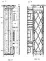
- FIGS. 1C, 1D, and 1Eare front elevation, rear elevation, and left side elevation views, respectively, of the product display merchandiser of FIGS. 1A-1B , the right side elevation view being a mirror image of the left side elevation view.
- FIGS. 1F and 1Gare top and bottom views, respectively, of the product display merchandiser of FIGS. 1A-E illustrating the merchandiser with the tray in a first, retracted position.
- FIGS. 1H, 1I, 1J, and 1Kare alternate perspective, left side elevation, top view, and bottom view, respectively, of the product display merchandiser of FIGS. 1A-1G illustrating the merchandiser with the tray in a second, extended position.
- FIGS. 1L and 1Mare perspective views of an exemplary removable divider illustrating, in FIG. 1L , one form of mating structure that may be used to mate the divider to the merchandiser unit, and illustrating in FIG. 1M , an exemplary manner in which the removable divider may be stored on the merchandiser for future use.
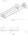
- FIG. 2is a perspective view of an alternate product display merchandiser in accordance with aspects of the invention taken from above the rear right corner of the merchandiser and illustrating the merchandiser with an alternate form of mounting bracket intended for use with bar mounted systems rather than grid systems, including alternate side members or wings for larger product and an exemplary pusher attachment accessory (note: while a bar mounting bracket and a grid mounting bracket are shown for comparison purposes, it should be understood that the merchandiser would be equipped with either two bar mounting brackets or two grid mounting brackets, rather than a combination of either).
- FIG. 3is a top view of an alternate product display merchandiser in accordance with embodiments of the invention illustrating an optional front and/or rear stabilizer member connected to the mounting brackets for stabilizing same.
- FIG. 4Ais a perspective view of another product display merchandiser in accordance with embodiments of the invention taken from above and behind the merchandiser (or the right rear corner of the unit) and illustrating an alternate baseless tray or drawer type merchandiser design with an alternate manner for adjusting the side members or wings of the unit to adjust width of the merchandiser and an alternate means for securing the tray in the first, retracted position so as to avoid inadvertent movement of the merchandiser to the second, extended position (note: the left side member or wing is adjusted to a wider position than the right side member or wing simply to show that the merchandiser does not have to be setup symmetrically if desired).
- FIG. 4Bis a perspective view of the merchandiser of FIG. 4A taken from below and in front of the merchandiser (or the lower left front corner of the unit) and illustrating the alternate rear stabilizer and adjustable width mechanism of the merchandiser.
- FIG. 4C-Dare front elevation and rear elevation views of the product display merchandiser of FIGS. 4A-B again illustrating how the width of the left side member or wing has been adjusted more than the right (or the left side member has been displaced further from the center of the merchandiser or from a central axis running through the center of the merchandiser than the right side member is from the central axis).
- FIGS. 4E, 4F, and 4Gare left side elevation, top, and bottom views, respectively of the product display merchandiser of FIGS. 4A-D illustrating the merchandiser in the same first, retracted or closed position the merchandiser is illustrated in for FIGS. 4A-D .
- FIGS. 4H and 41are alternate perspective and left side elevation views, respectively, of the merchandiser of FIGS. 4A-G illustrating the merchandiser in a second, extended or open position in which a store associate may place the merchandiser for stocking or restocking purposes.
- FIG. 4Jis an enlarged, partial perspective view of the tray portion of the merchandiser of FIGS. 4A-41 illustrating how the width of the side members may be adjusted and how a user may keep track of same (again noting the left side member is illustrated as being adjusted to a wider position than the right side member).
- FIG. 4Kis a cross-section of the merchandiser of FIG. 4J taken along line 4 K- 4 K.
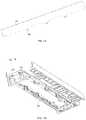
- FIG. 4Lis a partial perspective view of only a portion of the merchandiser of FIGS. 4A-4K illustrating the support brackets, first and second stabilizing members and a baffle structure for directing air from a rear of the merchandiser toward the front of the merchandiser and, thus, from the rear of any open-air refrigeration unit the merchandiser may be installed in toward the front of the open air refrigeration unit in order to assist in keeping product within the refrigeration unit at a generally uniform temperature.
- the front stabilizeralso has a first mating structure for engaging a portion of the remainder of the merchandiser unit in order to retain the unit in the retracted position and/or prevent inadvertent movement of the merchandising unit to the second, extended position.
- FIG. 4Mis a partial perspective view of only a portion of the merchandiser of FIGS. 4A-4K illustrating second mating structures for engaging with the first mating structures of the merchandiser portions of FIG. 4L in order to retain the merchandising unit in the retracted position and/or to prevent inadvertent movement of the merchandising unit to the second, extended position.
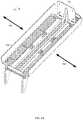
- FIGS. 4N, 4O, and 4Pare partial perspective views of the stabilizer located at the rear portion of the merchandiser of FIG. 4L illustrating from the front ( FIG. 4N ) and rear ( FIG. 4O ) how the baffle is inserted into or nested within the rear stabilizer and how the rear stabilizer is connected to the side members, and further illustrating in FIG. 4P what the rear stabilizer looks like when removed from the merchandiser.
- FIGS. 4Q and 4Rare partial perspective views of the tray and a side member, respectively, depicting one exemplary mechanism for securing a side member to the tray.
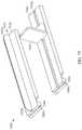
- FIG. 5Ais an exploded view of another product display merchandiser in accordance with embodiments of the inventive subject matter having an alternate manner for adjusting the side member or wings of the unit to adjust width of the merchandiser.
- FIGS. 5B and 5Care perspective views of the side members or wings of the product display merchandiser depicted in FIG. 5A .
- FIG. 5Dis a perspective view of a tray of the product display merchandiser depicted in FIG. 5A .
- FIG. 5Eis a perspective view of a product display merchandiser with a lens removed.
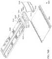
- FIG. 6Ais a partial perspective view of another product display merchandiser in accordance with embodiments of the inventive subject matter having a mechanism to securely attach a bracket engagement member to a rear stabilizer
- FIG. 6Bis an exploded view of the bracket engagement member and rear stabilizer of the product display merchandiser depicted in FIG. 6A .
- FIG. 6Cis an exploded view of the bracket engagement member of the product display merchandiser depicted in FIG. 6A .
- FIG. 6Dis an exploded view of the rear stabilizer of the product display merchandiser depicted in FIG. 6A .
- FIG. 7Ais a perspective view of another product display merchandiser in accordance with embodiments of the inventive subject matter in which one or more of the product display merchandiser's sidewalls or wings is removable.
- product display merchandiserscan be arranged in a linear fashion and a sidewall or wing of an adjacent product display merchandiser can provide support for a product displayed in the product display merchandiser.
- FIG. 7Bis a perspective view of the product display merchandiser of FIG. 7A in an extended position in which product can be loaded onto the product display merchandiser from the side.
- FIG. 8is a top perspective view of a ventilated merchandising system in accordance with one embodiment of the present invention.
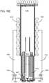
- FIG. 9Ais a partial rear perspective view of a ventilated merchandising system without plenum plates in accordance with one embodiment of the present invention.
- FIG. 9Bis a rear perspective view of a base member, separator, tray and mounting brackets of a ventilated merchandising system in accordance with one embodiment of the present invention.
- FIG. 10is a bottom view of a separator, front plate and plenum plates of a ventilated merchandising system in accordance with one embodiment of the present invention.
- FIG. 11is a top perspective view of a base member of a ventilated merchandising system in accordance with one embodiment of the present invention.
- FIG. 12is a top perspective view of a ventilated merchandising system in accordance with one embodiment of the present invention.
- FIG. 13is a top perspective view of a ventilated merchandising system with arms expanded and in product loading position in accordance with one embodiment of the present invention
- FIG. 14is a bottom view of a tray and arms of a ventilated merchandising system in accordance with one embodiment of the present invention.
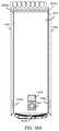
- FIG. 15is a side view of a ventilated merchandising system in accordance with one embodiment of the present invention.
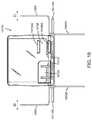
- FIG. 16Ais a bottom view of a ventilated merchandising system in accordance with one embodiment of the present invention.
- FIG. 16Bis a bottom view of a ventilated merchandising system in accordance with another embodiment of the present invention.
- FIG. 16Cis a bottom view of the embodiment in FIG. 16A , without a base member;
- FIG. 16Dis a bottom view of the embodiment in FIG. 16A with arms expanded;
- FIG. 16Eis a bottom view of the embodiment in FIG. 16A with arms expanded and in product loading position;
- FIG. 17is a bottom perspective view of a ventilated merchandising system in accordance with one embodiment of the present invention.
- FIG. 18is a top perspective view of a ventilated merchandising system with arms expanded in accordance with one embodiment of the present invention.
- FIG. 19is a front view of a ventilated merchandising system with arms expanded in accordance with one embodiment of the present invention.
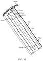
- FIG. 20is a bottom perspective view of a separator and front plate of a ventilated merchandising system in accordance with one embodiment of the present invention.
- FIG. 21is a rear view of a ventilated merchandising system in accordance with one embodiment of the present invention.
- FIG. 22Ais a top view of a ventilated merchandising system in accordance with one embodiment of the present invention.
- FIG. 22Bis a detail side perspective view of the rear portion of a ventilated merchandising system in accordance with one embodiment of the present invention.
- FIG. 22Cis a detail side perspective view of the rear portion of a ventilated merchandising system in accordance with one embodiment of the present invention.
- FIG. 22Dis a detail top perspective view of the rear portion of a ventilated merchandising system in accordance with one embodiment of the present invention.
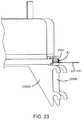
- FIG. 23is a detail side perspective view of the rear portion of a ventilated merchandising system in accordance with one embodiment of the present invention.
- FIG. 24Ais a schematic side view of ventilated merchandising systems with products displayed and installed in a refrigerator or freezer case;
- FIG. 24Bis a front view of a grid system
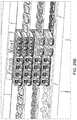
- FIG. 25Ais a schematic of numerous merchandising systems with products displayed and installed on a grid system
- FIG. 25Bis a schematic of numerous ventilated merchandising systems with products displayed and installed in a refrigerator case
- FIG. 26is a schematic view of numerous ventilated merchandising systems installed in a refrigerator case.
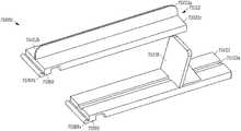
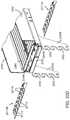
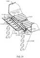
- FIG. 27is a top perspective view of a ventilated merchandising system in accordance with another embodiment of the present invention.
- FIG. 28is an exploded view of a ventilated merchandising system in accordance with the embodiment shown in FIG. 27 ;
- FIG. 29is a rear perspective view of a ventilated merchandising system in accordance with the embodiment shown in FIG. 27 ;
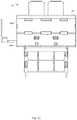
- FIG. 30is a front view of a ventilated merchandising system in accordance with the embodiment shown in FIG. 27 ;
- FIG. 31is a side perspective view of the rear portion of a ventilated merchandising system in accordance with the embodiment shown in FIG. 27 ;
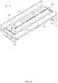
- FIG. 32is a top view of a ventilated merchandising system in accordance with the embodiment shown in FIG. 27 ;
- FIG. 33is a bottom view of a tray and side arms of a ventilated merchandising system in accordance with the embodiment shown in FIG. 27 ;
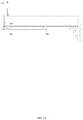
- FIG. 34is a side view of a ventilated merchandising system in accordance with the embodiment shown in FIG. 27 ;
- FIG. 35is a bottom view of a ventilated merchandising system in accordance with the embodiment shown in FIG. 27 ;
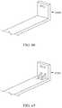
- FIG. 36Ais a perspective view of a baffle system coupled to a merchandising shelf in accordance with another embodiment of the present invention.
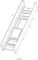
- FIG. 36Bis a perspective view of a standard merchandising shelf to which a baffle system may be coupled in accordance with the embodiment in FIG. 36A ;
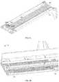
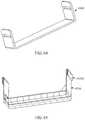
- FIG. 37is a perspective view of a baffle system in accordance with the embodiment in FIG. 36A ;
- FIG. 38is a top view of a baffle system in accordance with the embodiment in FIG. 36A ;
- FIG. 39is a bottom view of a baffle system in accordance with the embodiment in FIG. 36A ;
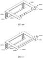
- FIG. 40is a top view of a baffle system coupled to a merchandising shelf in accordance with the embodiment in FIG. 36A ;
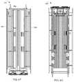
- FIG. 41is a side view of a baffle system coupled to a merchandising shelf in accordance with the embodiment in FIG. 36A ;
- FIG. 42is a front view of a baffle system coupled to a merchandising shelf in accordance with the embodiment in FIG. 36A ;
- FIG. 43is a perspective view of a baffle system coupled to a merchandising shelf in accordance with the embodiment in FIG. 36A , attached to a grid system;
- FIG. 44is a perspective view of a baffle system coupled to a merchandising shelf in accordance with the embodiment in FIG. 36A , attached to a grid system;
- FIG. 45is a rear perspective view of a baffle system coupled to a merchandising shelf in accordance with the embodiment in FIG. 36A , attached to a grid system;
- FIG. 46is a side perspective view of a baffle system coupled to a merchandising shelf in accordance with the embodiment in FIG. 36A , attached to a grid system.
- FIG. 47Ais a top perspective view of a ventilated merchandising system in accordance with one embodiment of the present invention.
- FIG. 47Bis a bottom view of the ventilated merchandising system of FIG. 47A .
- FIG. 48is a top perspective view of a base member of a ventilated merchandising system in accordance with one embodiment of the present invention.
- FIG. 49Ais a top perspective view of a front plate of a ventilated merchandising system in accordance with one embodiment of the present invention.
- FIG. 49Bis an exploded view of the front plate of FIG. 49A .
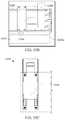
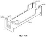
- FIG. 50Ais a top perspective view of a front plate of a ventilated merchandising system in accordance with another embodiment of the present invention.
- FIG. 50Bis a bottom view of the front plate of FIG. 50A .
- FIG. 51Ais a top perspective view of a front plate of a ventilated merchandising system in accordance with another embodiment of the present invention.
- FIG. 51Bis a side perspective view of the front plate of FIG. 51A .
- FIGS. 52A-Fare front bottom perspective, side bottom perspective, bottom rear perspective, top rear perspective, bottom front perspective, and left-front perspective views, respectively, of another embodiment of a shelf-mounted pull-out tray merchandiser in accordance with aspects of the invention.
- FIG. 53is a side perspective view of the rear bracket illustrated in FIG. 52A for securing the merchandiser to a shelf.
- FIGS. 54A-Eare right-side perspective, rear-right perspective, bottom rear-left perspective, front left-side perspective and bottom front perspective views, respectively, of another embodiment of a shelf-mounted pull-out tray merchandiser in accordance with other aspects of the invention, illustrating the merchandiser connected to a side of the shelf (instead of the usual rear of the shelf) for illustrative purposes.
- FIGS. 55A-Eare additional views of an alternate embodiment of a shelf-mounted pull-out tray merchandiser in accordance with aspects of the invention, with FIGS. 55A-B being bottom side perspective and bottom rear perspective views, respectively, and FIGS. 55C-E being side perspective, front perspective and side close-up views of the rear spacer accessory illustrated in FIGS. 55A-B and illustrating a rear bracket that does not extend beyond the rear end of the merchandiser.
- FIGS. 56A-Bare rear side perspective and perspective views, respectively, of an alternate rear spacer accessory in accordance with other embodiments of the invention and illustrating a rear spacer accessory with a bracket that extends beyond the rear end of the merchandiser.
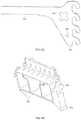
- FIGS. 57A-Bare perspective and enlarged perspective views of a conventional retail store gondola shelf illustrating existing circular openings in the surfaces thereof and traditional gaps that exist between the rear of the horizontal shelf portion and the vertical upright portion of the gondola.
- FIGS. 58A-Bare top-right perspective and right-side perspective views of an alternate shelf-mounting accessory for a pull-out tray merchandiser in accordance with other embodiments of the invention illustrating a rear bracket with an optional spacer mechanism for filling the gap illustrated in FIGS. 57A-B to securely hold a shelf-mounted tray to the shelving unit.
- FIGS. 59A-Eare top rear perspective, top, rear elevation, right side elevation and cross-sectional views, respectively, of another shelf-mounting accessory in accordance with embodiments of the invention, with the cross-section of FIG. 59E being taken along line 59 E- 59 E in FIG. 59C .
- FIG. 60is a left-front perspective view of an alternate shelf-mounting accessory in accordance with the invention illustrating a rear bracket that has male mating members for mating with existing female structures in a pull-out tray and a lower return portion that can be adjusted to different positions in order to accommodate shelves of different thicknesses.
- FIG. 61is a left-front perspective view of an alternate shelf-mounting accessory in accordance with the invention illustrating a rear bracket that has an alternate mating structure for engaging the rear of the pull-out tray merchandiser and having a lower return portion that can be adjusted to different positions in order to accommodate shelves of different thicknesses.
- FIGS. 62A-Care top perspective, bottom rear perspective and bend pattern views of an alternate shelf-mounting accessory in accordance with embodiments of the invention illustrating a metal bracket that mounts to a pull-out tray via metal support arms similar to those used to mount the tray to a bar/grid/vertical gondola upright wall.
- FIG. 63is a perspective view of a shelf-mounting accessory for a pull-out tray in accordance with other embodiments of the invention.
- FIG. 64is a perspective view of an alternate shelf-mounting accessory for a pull-out tray in accordance with other embodiments of the invention.
- FIG. 65is a perspective view of an alternate shelf-mounting accessory for a pull-out tray in accordance with other embodiments of the invention.
- FIG. 66is a perspective view of one end of an alternate shelf-mounting accessory for a pull-out tray in accordance with other embodiments of the invention.
- FIG. 67is a perspective view of one end of an alternate shelf-mounting accessory for a pull-out tray in accordance with other embodiments of the invention.
- FIG. 68Ais a perspective view of a front portion of a product display merchandiser with a pull out tray having an alternate shelf-mounting accessory in accordance with other embodiments of the invention.
- FIG. 68Bis a perspective view of the shelf-mounting accessory of FIG. 68A .
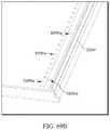
- FIG. 69Ais a perspective view of a shelving unit having a shelf having an alternate shelf-mounting accessory in accordance with other embodiments of the invention.
- FIG. 69Bis an expanded view of the shelf of FIG. 69A showing the shelf-mounting accessory.
- FIG. 69Cis an end view of the shelf-mounting accessory of FIGS. 69A-69B showing a cooperating shelf-mounting accessory for a pull-out tray.
- FIG. 70is an end view of an alternate shelf-mounting accessory for a shelf surface in accordance with other embodiments of the invention.
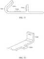
- FIG. 71is an end view of an alternate shelf-mounting accessory for a shelf surface in accordance with other embodiments of the invention.
- FIG. 72is a perspective view of one end of an alternate shelf-mounting accessory for a pull-out tray in accordance with other embodiments of the invention.
- FIG. 73Ais a perspective view of a product display having a shelf mounting accessory in accordance with other embodiments of the invention.
- FIGS. 73B-73Care left and right perspective views of the product display of FIG. 73A .
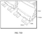
- FIG. 73Dis a perspective view of the product display of FIGS. 73A-73C with the shelf-mounting accessory for a shelf surface removed to better illustrate the shelf-mounting accessories for the trays.
- FIG. 74is a perspective view of a product display having a shelf mounting accessory in accordance with other embodiments of the invention.
- FIG. 75is a perspective view of a product display having a shelf mounting accessory in accordance with other embodiments of the invention.
- FIG. 76Ais a perspective view of a product display having a shelf mounting accessory in accordance with other embodiments of the invention.
- FIGS. 76B-76Care exploded views of the product display of FIG. 76A .
- FIGS. 76D-76Eare top and bottom perspective views of the shelf mounting accessory for the tray of the product display of FIGS. 76A-76C .
- FIGS. 1A-1Mand the associated text, generally depict and describe a first embodiment of a product display, wherein the product display has a baseless design, FIG. 2 and its associated text generally depict a second embodiment, FIG. 3 and its associated text generally depict a third embodiment, FIGS.
- FIGS. 4A-Rand the associated text, generally depict and describe a fourth embodiment of a product display merchandiser, wherein the product display merchandiser has an adjustable width and a unique stabilizing structure
- FIGS. 5A-5Eand the associated text, generally depict and describe a fifth embodiment of a product display merchandiser, wherein the product display merchandiser has an alternate mechanism for adjusting the position of, and securing, the sidewalls or wings and alternate structures for retaining displayed product in the merchandiser when the lens is removed
- FIGS. 6A-6Dand the associated text, generally depict and describe a sixth embodiment of a product display merchandiser, wherein the product display merchandiser includes a mechanism to securely attach a bracket engagement member to a rear stabilizer, and FIGS.
- FIG. 7A-7Bgenerally depict and describe a seventh embodiment of a product display merchandiser, wherein the product display merchandiser includes one or more removable sidewalls or wings for use in unison with one or more other product display merchandisers.
- the product display merchandiserincludes one or more removable sidewalls or wings for use in unison with one or more other product display merchandisers.
- FIGS. 1A-1Millustrate an exemplary embodiment of a product display merchandiser 100 , according to some forms of the inventive subject matter.
- the product display merchandiser 100includes a tray 102 for holding a product to be displayed.
- the tray 102is supported underneath by arms, support members, brackets, or “blades” 116 .
- the arms 116include bracket engagement members 112 that attach to a rear support member (not shown), such as a vertical upright of a conventional gondola or other store shelving system.
- the rear support membercan be any suitable support member such as conventional grid-type systems, bar type systems, shelves, etc.
- the product display merchandiser 100can also have one or more stabilizers positioned in various locations on the product display merchandiser 100 . For example, FIG.
- the product display merchandiser 100can include a stabilizer, in addition to or in lieu of the stabilizer 114 , near the front of the product display merchandiser 100 .
- the stabilizer 114(as well as any other stabilizers) can be sized so as to accommodate trays of multiple dimensions.
- the product display merchandiser 100can also include a lens 106 for holding and displaying signage, preventing product from falling out of the tray 102 , etc.
- a lenscan be formed from any suitable material and in any suitable manner.
- the lenscan be extruded or injection molded plastic. Additionally, in one form, the lens can have perforations which allow for easy snap-off type custom-sizing of the lens.
- the product display merchandiser 100has multiple positions.
- the product display merchandiser 100can have a closed position (best shown in FIGS. 1A-1B, and 1E-1G ) for presenting product and an open position (best shown in FIGS. 1H-1K ) for restocking product.
- a closed positiona majority of the tray 102 is positioned over top of the arms 116 .
- the open positionthe majority of the tray 102 is not positioned over top of the arms 116 .
- the tray 102travels along the arms 116 from the closed position to the open position in a direction indicated by arrow 126 .
- the tray 102includes tracks 120 through which the arms 116 extend.
- the tracks 120can take any suitable form.
- the tracks 120can comprise a number of individual pieces protruding from the tray 102 , a continuous or semi-continuous channel running along the tray 102 , etc. Additionally, the tracks 120 (and/or arms 116 ) can include ball bearings or any other suitable friction-reducing mechanism.
- the product display merchandiser 100includes a mechanism that resists movement of the tray 102 between the open and closed positions. Such a mechanism can prevent the tray 102 from moving from the closed position to the open position unintentionally.
- the product display merchandiser 100can include a handle 110 (also seen in FIG. 1K ) with first engagement members 108 .
- the arms 116can include second engagement members 104 that are complimentary to the first engagement members 108 .
- Such first engagement members 108 and second engagement members 104are well-depicted in FIG. 1E .
- the engagement membersare engaged when the tray 102 is in the closed position. Such engagement resists and/or prevents movement of the tray 102 to the open position.
- FIG. 1EThe engagement members are engaged when the tray 102 is in the closed position. Such engagement resists and/or prevents movement of the tray 102 to the open position.
- operation of the handle 110disengages the engagement members.
- Such disengagementpermits movement of the tray 102 from the closed position to the open position.
- the first engagement members 108disengage from the second engagement members 104 when the handle 110 is displaced in a direction parallel to the movement of the tray 102 across the arms 116 (i.e., in the direction of arrow 126 ).
- movement of the handle away from the bracket engagement members 112disengages the first engagement members 108 from the second engagement members 104 .
- the handle 110may displace in a somewhat rotational manner.
- the handle 110can be affixed to the tray 102 near a leading edge of the tray (i.e., a portion of the tray opposite the bracket engagement members 112 ).
- the handle 110is operated from an end of the handle 110 opposite a side of the handle 110 affixed to the tray 102 .
- the handle 110displaces in a somewhat rotational direction that, for purposes of this specification, can be considered to have a displacement in a direction parallel to the motion of the tray 102 and in a direction perpendicular to the motion of the tray 102 .
- the product display merchandiser 100can include a mechanism that prevents the tray 102 from moving from the open position to the closed position during restocking.
- the arms 116 and the tracks 120can include complimentary engagement members that engage when the tray 102 is in the open position. Such engagement members can provide mechanical resistance which must be overcome to move the tray 102 from the open position to the closed position.
- FIG. 1Idepicts a product display merchandiser 100 with arms having an arm engagement member 144 which engages a track engagement member 136 . When the tray 102 is in the open position, the track engagement member 136 engages the arm engagement member 144 and provides resistance against the tray 102 moving from the open position to the closed position.
- such resistanceis physical and is overcome by force being exerted on the tray 102 in a direct of the closed position.
- the product display merchandiser 100includes a tray 102 and arms 116 .
- the tray 102includes tracks 120 through which the arms 116 extend.
- the tray 102displaces along the arms 116 .
- the arms 116can include bracket engagement members 112 configured to mount to a rear support member (not shown).
- FIG. 1Bdepicts the product display merchandiser 100 configured with bracket engagement members 112 to mount to a rear stabilizer, in some embodiments, the product display merchandiser 100 can be configured to be supported by, attach to, and/or rest on a shelf.
- the tray 102includes a right sidewall 124 and a left sidewall 126 (also referred to as a “side members” or “wings”), as well as a lens 106 .
- a right sidewall 124 and a left sidewall 126also referred to as a “side members” or “wings”
- a lens 106a lens 106 .
- either (or both) of the right sidewall 124 and the left sidewall 126are extendable to accommodate product of varying dimensions.
- the tray 102 of FIG. 1Bis depicted with the right sidewall 124 extended. In one form, the right sidewall 124 and left sidewall 126 are incrementally extendable.
- the right sidewall 124 and the left sidewall 126can be individually extendable or mechanically coupled in such a way that extension of one of the right sidewall 124 and the left sidewall 126 cause extension of the other of the right sidewall 124 and the left sidewall 126 .
- some embodiments of the product display merchandiser 100include a removable divider 130 .
- the removable product divider 130is shown in greater detail in FIG. 1L .
- the removable divider 130can attach to the product display merchandiser 100 in any suitable manner.
- the removable divider 130can include divider protrusions 148 that mate with slots 118 on the tray 102 (as shown in FIG. 1G ), slots which mate with protrusions on the tray 102 , a bar that mates with a track on the tray 102 , etc.
- the removable divider 130is mountable at multiple locations of varying distance from the right sidewall 124 and the left sidewall 126 .
- the product display merchandiser 100When removed, the product display merchandiser 100 preferably includes a storage space for the removable divider 130 .
- FIG. 1Mdepicts one example by which the removable divider 130 can be stored onboard the product display merchandiser 100 .
- the tray 102includes a recess on a bottom side of the tray 102 configured to accommodate and store the removable divider 130 .
- the tray 102can include clips 150 (or other suitable connectors) which hold the removable divider 130 in a stored position on the product display merchandiser 100 .
- a divider 142(whether or not removable) can take the form of a “T-shape.”
- a horizontal portion of such divider 142can form a product support surface 140 .
- This product support surface 140can support a portion of product displayed in the product display merchandiser and a second product support surface 138 located on the sidewall can support another portion of the product displayed in the product display merchandiser 100 .
- the tray 102also includes pushers 122 .
- the pushers 122act to urge product toward the front of the tray 102 (i.e., front face product) making the product easier to access.
- FIG. 1Bdepicts the tray 102 as including pushers 122 , some embodiments of the inventive subject matter do not include pushers 122 to urge product to the front of the tray.
- the product display merchandiser 100may be configured to incline, or mount on an incline, in a manner in which gravitational force is employed to urge product to the front of the tray 102 .
- FIG. 1Bdepicts a product display merchandiser 100 including two pushers 122
- the pushers 122generally comprise a vertical member and a biasing mechanism.
- the pushers 122can employ any suitable biasing mechanism, such as a spring, a counterweight, a pulley system, etc.
- the pushers 122include engagement members (e.g., clips, latches, detents, etc.) that engage with complimentary engagement members located on the tray 102 , tracks 120 , and/or arms 116 .
- the engagement members and the complimentary engagement membersact to maintain the pushers 122 in a restocking position when the tray 102 is in an open position. Maintaining the pushers 122 in the restocking position not only makes restocking easier but also helps prevent product from being damaged during the restocking process. In some embodiments, the pushers 122 are maintained at a backmost portion of the tray 102 during restocking. In some embodiments, the engagement members and the complimentary engagement members automatically disengage when the tray 102 is moved from the open position to the closed position.
- the tray 102 , tracks 120 , and/or arms 116can include disengagement members that cause disengagement of the engagement members from the complimentary engagement members. FIGS.
- FIG. 1Jdepicts two engagement members 146 coupled to the pushers 122 .
- FIG. 1Jdepicts an embodiment including two pushers 122 and two engagement members 146 , it is not necessary that there be a one-to-one correspondence between the pushers 122 and engagement members 146 .
- the two engagement members 146act (in concert with the complimentary engagement members) to maintain the pushers 122 in the restocking position when the tray 102 is in the open position.
- FIGS. 1D and 1Hdepict a product display merchandiser 100 having disengagement members 132 .
- the disengagement members 132are linearly aligned with the pushers 122 and correspond one-to-one with the pushers 122 , although embodiments exist that do not have either of these features (e.g., one form may have one disengagement member 132 and three pushers 122 ).
- the disengagement members 132act to disengage the engagement members 146 and the complimentary engagement members when the tray 102 is moved from the open position to the closed position. Such action by the disengagement members 132 causes the pushers 122 to be automatically removed from the restocking position.
- the disengagement members 132are protrusions that physically contact one or more of the engagement members and the complimentary engagement members to force disengagement of the engagement members and the complimentary engagement members.
- FIG. 1Cis a front view of a product display merchandiser 100 , according to some embodiments of the inventive subject matter.
- the product display merchandiser 100includes a lens 106 .
- the lens 106can hold and/or display signage, prevent product from falling out of the tray 100 , etc.
- Such a lenscan be formed from any suitable material and in any suitable manner.
- the lenscan be extruded or injection molded plastic.
- the lenscan have perforations which allow for easy snap-off type custom-sizing of the lens.
- the lens 106can have multiple display sections or channels.
- the lens 106may have a first display portion 106 A and a second lens portion 106 B.
- FIG. 1Cdepicts lens 106 as having the second display portion 106 B arranged above the first display portion 106 A, many other configurations exist.
- the lens 106may have left and right display sections, or any other combination of two or more display sections.
- FIGS. 1A-1Mthe product tray is referred to generally by reference number 102 , while the product tray is referred to as 202 , 302 , and 402 , in FIG. 2 , FIG. 3 , and FIG. 4A-4R , respectively.
- FIGS. 1A-1Mdepict a first embodiment of a product display merchandiser 100
- FIG. 2depicts a second embodiment of a product display merchandiser 200 , according to some embodiments of the inventive subject matter.
- the product display merchandiser 200includes sidewalls 228 , pushers 222 A and 222 B, bracket engagement members 212 , and a pusher attachment 252 .
- the pusher attachment 252attaches to the pusher 222 B to expand the surface area of the pusher 222 B.
- Additional types of pusher attachmentsexist. For example, pusher attachments can be designed for specific products, to minimize the surface area of the contact point with a product, to extend the depth of the pusher, etc. Additionally, FIG.
- FIG. 2depicts a bracket engagement member 212 that is configured to engage a bar mounted system (not shown). Additionally, FIG. 2 depicts an embodiment of a product display merchandiser in which a horizontal portion of the sidewall 228 (i.e., the product support 238 portion of the sidewall) is roughly equal in area to a vertical portion of the sidewall 228 .
- FIG. 2depicts a second embodiment of a product display merchandiser
- FIG. 3depicts a third embodiment of a product display merchandiser 300 , according to some embodiments of the inventive subject matter.
- the product display merchandiser 300includes a tray 302 that is slidable along arms 316 .
- the tray 302includes tracks 320 disposed on the bottom side of the tray 302 .
- the arms 316are seated in the tracks 320 .
- the tray 302moves in a direction as indicated by arrow 326 from an open position (shown) to a closed position (not shown). When in the open position, a void (or unobstructed opening) 358 is revealed (i.e., the product display merchandiser 300 has a baseless design).
- the void 358is bounded on a left side and a right side by arms 416 , on a front side by front stabilizer 354 , and on a rear side by rear stabilizer 356 .
- the trayalso includes pushers 322 A and 322 B which are movable within in the tray 302 and a handle 310 .
- the handle 310is operable to disengage engagement members so as to allow the tray 302 to be moved from the closed position to the open position.
- the tray 302includes a divider 330 / 342 .
- the divider 330 / 342can be fixed to the tray 302 or removably attached to the tray 302 .
- FIG. 3depicts a third embodiment of a product display merchandiser
- FIGS. 4A-4Rdepict a fourth embodiment of a product display merchandiser 400 having an extendable tray width.
- FIG. 4Ais an upper perspective view of a fourth embodiment of the product display merchandiser 400 having adjustable side members 428 , according to some embodiments of the inventive subject matter.
- the product display merchandiser 400 depicted in FIG. 4Ahas one pusher 422 and movable sidewalls 428 .
- the sidewalls 428are extendable from the tray in directions indicated by arrows 426 . Extension of the sidewalls 428 allows for the tray width to be adjusted.
- the trayalso includes first mating members 476 (best shown in FIG. 4Q ) into which corresponding protrusions 478 (best shown in FIG. 4R ) can seat to secure the sidewalls 428 in an extended position.
- a horizontal portion of the sidewalls 428includes second mating members (e.g., protrusions 478 extending from the horizontal portion of the sidewalls 428 , as depicted in FIG. 4R ) which fit into the first mating members 476 .
- the second mating members“snapfit” into the first mating members 476 .
- a personcan lift an edge of one of the sidewalls 428 to disengage the second mating members from the first mating members 476 .
- the sidewalls 428are secured to the product display by one or more housing members or cords. Such housing members or cords can prevent the sidewalls 428 from becoming completely detached from the product display merchandiser 400 when disengaged.
- each of the sidewalls 428are independently movable. For example, a first of the two sidewalls 428 can be moved, and then a second of the two sidewalls 428 can be moved independently of the first.
- the sidewalls 428can be coupled in such a manner that when one of the two sidewalls 428 is moved, the other of the two sidewalls 428 moves in a corresponding manner.
- the product display merchandiser 400includes linear guides 477 , depicted in FIGS. 4J and 4K .
- the linear guides 477help ensure that the sidewalls 428 travel linearly with respect to the product display merchandiser 400 when moved between positions.
- the linear guides 477are protrusions that are seated in recess disposed in a horizontal portion of the sidewalls 428 .
- FIG. 4Qdepicts the first mating members 476 as incrementally spaced slots
- any suitable mechanism for securing the sidewalls in an extended positionmay be employed.
- one continuous aperture extending in a direction parallel to the direction in which the sidewalls 428 extendcan be utilized.
- any suitable fastenere.g., a screw and nut combination
- a horizontal portion of the sidewallscan include a threaded shaft which protrudes through the continuous aperture.
- the sidewallcan be secured with a nut fastened to the threaded shaft.
- the horizontal portion of the sidewallcan include an internally threaded aperture and the sidewall can be secured by inserting a screw through continuous aperture into the internally threaded aperture.
- FIG. 4Rdepicts the second mating members 478 as protrusions and the first mating members as incrementally spaced slots
- any suitable combination of second mating members 478 and first mating members 476can be used.
- the second mating members 478can be shaped as pegs and the first mating members 476 can take the form of complementarily apertures in which the pegs can be seated.
- FIG. 4Bis a lower perspective view of the product display merchandiser 400 depicted in FIG. 4A .
- the product display merchandiser 400includes tracks 420 (also well-depicted in FIG. 4M ) through which arms 416 extend.
- the tray 402is slidable along the arms in a direction as indicated by arrow 426 from a closed position (shown in FIG. 4E ) to an open position (shown in FIG. 41 ).
- FIG. 4Balso depicts a baffle 460 inserted on the underside of the product display merchandiser 400 and secured by a rear baffle mount 462 and a front baffle mount 464 .
- the baffle 460can server many different purposes, depending on a shape of the baffle 460 , a material from which the baffle 460 is made, and a position of the baffle 460 within the product display merchandiser 400 .
- the baffle 460can server to direct airflow through or around the product display merchandiser 400 .
- the baffle 460can be removably attached to the product display merchandiser 400 by insertion and removal from the rear baffle mount 462 and the front baffle mount 464 .
- FIG. 4Lalso depicts a first tray engagement mechanism 468 A- 468 D which acts to maintain the tray 402 in the closed position.
- a second tray engagement mechanism 470(best shown in FIG. 4M ) mates with the first tray engagement mechanism 468 A- 468 D when the tray is in the closed position.
- the rear baffle munt 462 and insert support surface 474are integral to the rear stabilizer 456 . Additionally, the rear stabilizer 456 can attach to the arms 416 via stabilizer engagement members 472 .
- FIGS. 4A-4Rdepict a fourth embodiment of a product display merchandiser 400 having an extendable tray width or adjustable width feature
- FIGS. 5A-5Edepict a fifth embodiment of a product display merchandiser 500 having an alternate manner for adjusting the width of the side members 528 , 524 and securing them in position so that they cannot be moved once the merchandiser is stocked with product and installed on a shelf, grid or bar.
- the product display merchandiser 500 of FIG. 5includes a left sidewall 528 , a right sidewall 524 , a tray 502 , arms 516 , a removable divider 530 , a lens 506 , and rear stabilizer 556 .
- the left sidewall 528 and right sidewall 524are securable to the tray 502 .
- the tray 502mounts to, and is supported, by the arms 516 .
- the tray 502is slidable along the arms 516 to an open or extended position making loading product onto the product display merchandiser 500 easier and in a manner that does not require a separate base structure that the tray slides upon.
- the positions of the left sidewall 528 and the right sidewall 524are adjustable or moveable with respect to the tray 502 . Such adjustability or movability allows the distance between the left sidewall 528 and the right sidewall 524 to be adjusted to accommodate products of varying size and dimension.
- the left sidewall 528 and right sidewall 524include tongue engagement portions 582 , e.g., grooves, (as shown in FIGS. 5B-5C ) that mate with the tongues 576 on the tray 572 .
- the tray 502can include tongue engagement portions or grooves 582 and the left sidewall 528 and the right sidewall 524 can include the tongues 576 .
- the tray 502may have tongue and tongue engagement portions and the sidewalls 524 , 528 may have tongue engagement portions and tongues that correspond with and/or mate with those on the tray 502 .
- the tongues 576mate with the tongue engagement portions or grooves 582 to secure the left sidewall 528 and the right sidewall 524 in a desired position on tray 502 .
- the tongues 576are formed into the tray 502 and include a raised portion that engages the tongue engagement portions of the left sidewall 528 and the right sidewall 524 .
- the tongues 576are deformable (e.g., can be pushed from a first, resting position to a second, deformed position) to disengage from the tongue engagement portions 582 and allow the position of one or more of the left sidewall 528 and the right sidewall 524 to be adjusted.
- the tongues 576 and/or tongue engagement portions 582can include a mechanism (e.g., an indexing mechanism) that allows movement of the left sidewall 528 and the right sidewall 524 between predefined or predetermined positions.
- a mechanisme.g., an indexing mechanism
- the tongues 576include protrusions 584 (e.g., finger members) that seat within the serrated boundaries of the tongue engagement portions 582 .
- protrusions 584e.g., finger members
- indiciamay be added to one or more serrations or grooves in order to make quick adjustments to that setting on one or many merchandisers.
- FIGS. 5A-5Edepict tongues 576 as having protrusions 584 and left sidewall 528 and right sidewall 524 as having tongue engagement portions 582 with serrated boundaries
- other mechanismsexist for allowing movement of the left sidewall 538 and the right sidewall 524 between predefined positions, such as those depicted and described in FIGS. 4A-4R and the associated text, or any other suitable mechanism.
- the left sidewall 528 and right sidewall 524include sidewall tabs 578 that mate with sidewall tab recesses 580 located on the tray 502 to aid in securing the sidewalls to the tray 502 and ensuring a desired position of the sidewalls is retained.
- tongue and groove type mating structuresmay be used to mate the sidewalls to the tray, other types of mating engagements may be used and, of these, they may be alternated so that some appear on both the tray and sidewalls.
- dovetail mating configurations or mortise and tenon mating configurationsmay be used.
- other protrusion and mating recess type configurationsmay be used.
- the mechanism described abovealso helps to ensure that the left sidewall 528 and right sidewall 524 will remain in desired positions after the width of the product display merchandiser 500 has been set. For example, to adjust the position of the left sidewall 528 and the right sidewall 524 the tongues 576 must be manipulated so that they no longer engage the tongue engagement portions 582 . Because the tongues 576 are positioned on the tray 502 , the tongues are not easily accessible when the product display merchandiser 500 contains product. Because the tongues 576 are not easily accessible, it is unlikely that they will be manipulated unintentionally (e.g., by an employee, heavy product, a customer, etc.).
- the left sidewall 528 and right sidewall 524remain in a relatively fixed position until such position is intentionally altered. Additionally, because the position of the left sidewall 528 and the right sidewall 524 is relatively fixed, some embodiments of the inventive subject matter are able to hold and display heavier products, as it is less likely that such products will cause the left sidewall 528 and the right sidewall 524 to move out of position. This is helpful in avoiding the merchandiser from inadvertently being changed by retailer stocking associates or the like after it has been set or configured in the desired manner to display specific products.
- the lens 506 of the product display merchandiser 500may be removable.
- the product display merchandisercan include stops, or protrusions, 594 , 596 .
- Such stops 594 , 596can prevent product from falling out of the product display merchandiser 500 when the lens 506 is removed.
- the stops 594can be integral to the tray 502 or left sidewall 528 and right sidewall 524 .
- the stop 596can be integral to the tray 502 or the center divider 530 (whether or not the center divider is removable). This allows product in certain situations to be advantageously displayed without a lens so that an unobstructed view of the displayed product may be seen by potential consumers.
- the wings or side members 528 , 524preferably will define product support surfaces extending inward toward the opposing side member 528 , 524 for supporting at least a portion of the displayed product.
- An example of this product support surfaceis illustrated in FIG. 5B for the left side member 528 .
- This product support surfaceruns from the rear of the merchandiser toward the front of the merchandiser and terminates in the protrusions or stops 594 , 596 .
- the side members 528 , 524preferably form stops or abutting surfaces that limit how close the side members 528 , 524 can be moved toward one another.
- each side member that define the tongue engagement openings or grooves 582 that protrusions or finger members 584 engageform distal ends that abut the opposing side member 528 , 524 to limit the travel of the side members 528 , 524 toward one another.
- the side members 528 , 524contain additional protruding members coplanar with the portions that define the tongue engagement openings 582 that further serve as abutment surfaces that limit travel of the side members 528 , 524 toward one another. These additional protrusions or protruding members are illustrated for the left side member 528 best in FIG. 5C and are positioned between the portions that define the tongue engagement openings 582 .
- FIGS. 5A-5Edepict a fifth embodiment of a product display merchandiser having an alternate manner for adjusting the side members
- FIGS. 6A-6Ddepict a sixth embodiment of a product display merchandiser 600 having a mechanism to securely attach a bracket engagement member 612 to a rear stabilizer 656 .
- the product display merchandiser 600includes a left sidewall 628 , a right sidewall 624 , arms 616 , a rear stabilizer 656 , a tray, and bracket engagement members 612 .
- the arms 616support the tray and are connected to the rear stabilizer 656 via the bracket engagement members 612 .
- the arms 616 and rear stabilizer 656connect to the bracket engagement members 612 .
- the bracket engagement members 612can be fastened to the rear stabilizer 656 .
- the bracket engagement members 612engage a vertical support (not shown) such as a bar mounted system or a grid mount system from which the product display merchandiser 600 can hang.
- a vertical supportsuch as a bar mounted system or a grid mount system from which the product display merchandiser 600 can hang.
- the bracket engagement members 612 and one arm 616are formed integral to one another as a metal support arm.
- the bracket engagement members 612include a locking receiver 686 that mates with a locking protrusion 688 located on the rear stabilizer 656 .
- the locking receiver 686 and the locking protrusion 688mate in such a way as to securely affix the bracket engagement member 612 to the rear stabilizer 656 .
- the locking receiver 686 and the locking protrusion 688can take any suitable form.
- the locking receiver 686can be an aperture through which the locking protrusion 688 extends, a cavity that receives the locking protrusion 688 , a clip to which the locking protrusion 688 attaches, etc.
- the locking protrusion 688is a piece of material that extends from the rear stabilizer 656 .
- the locking protrusion 688can be integral to the rear stabilizer 656 or a separate piece that is attached to the rear stabilizer 656 .
- the locking receiver 686can take the form of an aperture located in the bracket engagement member 612 .
- the locking protrusion 688 and the locking receiver 686are similarly shaped (or correspond in shape) and have a slightly different orientation (e.g., approximately 45° out of alignment).
- the locking protrusion 688 and the locking receiver 686can take any suitable shape. In the example depicted in FIGS.
- the locking protrusion 688 and the locking receiver 686are cross-shaped.
- the bracket engagement member 612is placed onto the rear stabilizer 656 in a first position such that the locking receiver 686 and the locking protrusion 688 are oriented in a similar direction.
- the bracket engagement member 612can be rotated to a second position, the second position being a display position for the product display merchandiser 600 .
- the locking protrusion 688acts on the bracket engagement member 612 to securely hold the bracket engagement member 612 and the rear stabilizer 656 together.
- the locking receiver 686may fit behind a larger portion of the locking protrusion 688 in such a manner as to experience a clamping force or camming force between an inner surface of the locking protrusion 688 and the rear stabilizer 656 .
- the protrusions 688correspond in shape with the locking receiver opening 686 so that the protrusion may be orientated into a position to be inserted into the opening 686 .
- the protrusion 688further defines a cutout, channel or groove that the locking receiver may be aligned with and then one or both the rear stabilizer 656 and integrated arm 616 and engagement member 612 are moved with respect to each other to securely clamp or fasten the integrated arm 616 and engagement member 612 to one end of the stabilizer 656 .
- the cutout, channel or grooveis configured to either cam against the engagement member 612 or form a friction fit with the engagement member 612 .
- the rear stabilizer 656can include an alignment protrusion 692 and the bracket engagement member 612 can include a mating alignment recess 690 .
- the alignment protrusion 692 and the alignment recess 690can be positioned in such a manner as to engage when the bracket engagement member 612 is in the second position.
- the alignment protrusion 692 and alignment recess 690can aid in assembly of the product display merchandiser 600 and provide greater stability to the product display merchandiser 600 .
- the mating alignment recess 690 and protrusion 692correspond in shape (e.g., both are circular or other curved structures, rectangular or triangular or other polygonal structures, etc.).
- FIGS. 6A-6Ddepict the rear stabilizer 656 as having the locking protrusions 688 and the bracket engagement member as having the locking receiver 686
- the rear stabilizer 656can include the locking receiver 686 and the bracket engagement member 612 can include the locking protrusion 688 .
- the bracket engagement member 612can include the alignment protrusion 692 and the rear stabilizer 656 can include the alignment recess 690 .
- many of the figuresdepict the arm 616 and the bracket engagement member 612 as a single piece, in some embodiments, the arm 616 is separate from, and attachable to, the bracket engagement member 612 .
- the engagement bracket 612does not have to move, but rather the rear stabilizer 656 could alternatively be moved or, in yet other forms, both could be moved with respect to each other.
- the two itemsare moved from a first position wherein the two items can be removed from one another or connected to one another, and then be moved to or toward a second position wherein the two items are secured to one another via a clamping or camming force or other fastening engagement.
- This same procedurecan be done for the protrusion 688 extending from the opposite side of the stabilizer and the other integrated engagement bracket and support arm illustrated on the opposite side of the stabilizer 656 .
- FIGS. 6A-6Ddepict a sixth embodiment of a product display merchandiser having a mechanism to securely attach a bracket engagement member to a rear stabilizer
- FIGS. 7A-7Bdepict a product display merchandiser 700 in which one or more of the product display merchandiser's 700 sidewalls is removable.
- the product display merchandiser 700includes a tray 702 , a left sidewall 728 attached to the tray 702 , and arms 716 .
- the tray 702is slidable along the arms 716 from a first retracted or closed position (depicted in FIG. 7A ) to an open, or extended position (depicted in FIG. 7B ).
- the product display merchandiser 700can also include a right sidewall (not shown). In the embodiment depicted in FIGS.
- the right sidewallhas been removed from the product display merchandiser 700 .
- two or more product display merchandiser 700can be mounted adjacent to one another so as to utilize one or more sidewalls of an adjacent product display merchandiser(s).
- all product display merchandisers 700 in an arrangement of product display merchandisers 700may have their right sidewalls removed (except for the rightmost product display merchandiser).
- product presented in a product display merchandiser 700will be supported on the left by the left sidewall 728 of the product display merchandiser 700 and on the right by the left sidewall of the right-adjacent product display merchandiser.
- the tray 702 and one or more of the left sidewall 728 and the right sidewallcan be designed in a complimentary manner such that the tray 702 and the left sidewall 728 and/or right sidewall create a continuous or nearly continuous surface.
- product display merchandisers 700are placed in closer proximity to one another, but also decreases difficulty in loading the product display merchandisers 700 .
- most product display merchandisershave two sidewalls and a base, allowing product stocking to be performed only from above the product display merchandiser (e.g., top loading of the merchandiser).
- product display merchandiser 700includes sidewalls that are removable, product can be stocked from the side (in addition to from above) (e.g., side loaded vs. top loaded).
- product display merchandisers that have removable sidewallscan be configured to have interchangeable sidewalls.
- sidewalls that are different heights, different widths, made of different materials, different shapes, different colors, etc.may be useful for different products or uses.
- product display merchandiserscan be repurposed for different applications or products by changing the removable/interchangeable sidewalls.
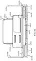
- FIGS. 8-26An embodiment of a ventilated merchandising system 830 for placement on a grid system 2410 of a refrigerator or cooler case 2420 is shown in the FIGS. 8-26 .
- every element numberstarts with the FIG number.
- the digits following the FIG numberidentify the specific elements. Some elements are substantially identical throughout multiple figures, and therefore may only be described once herein. If an element is not expressly described it is assumed to be substantially identical with an element in a previous drawing sharing the same identifying digits.
- FIGS. 8-26An embodiment of a ventilated merchandising system 830 for placement on a grid system 2410 of a refrigerator or cooler case 2420 is shown in the FIGS. 8-26 .
- every element numberstarts with the FIG number.
- the digits following the FIG numberidentify the specific elements. Some elements are substantially identical throughout multiple figures, and therefore may only be described once herein. If an element is not expressly described it is assumed to be substantially identical with an element in a previous drawing sharing the same
- the system 830includes a base member 940 , separator portion 1050 and tray 860 .
- the separator portion 1050 and the tray 860together form a platform coupled to the base member 940 for supporting products to be displayed.
- the separator 950is coupled to the base member 940 by flanges 941 , 942 which fit into slots 951 , 952 of the separator 950 .
- the slots 951 , 952 of the separator 950fit over the flanges 941 , 942 so that the entire separator 950 is slidably coupled to the base member 940 .
- lips 1053 A, 1053 B, 1054 A 1054 Bare located on the bottom of the separator 1050 . These lips 1053 A, 1053 B, 1054 A 1054 B fit into a groove 1148 coupled to a button 1147 on the base 1140 (other similar means of releasably engaging the separator 1050 to the base 1040 could also be used).
- the display mode seen in FIG. 8the front lips 1053 A, 1053 B are fit into the groove 1148 .
- the button 1147is pressed upward, causing the groove 1148 to move downward away from the separator 1050 and moving the groove 1148 away from the front lips 1053 A, 1053 B.
- the rear lips 1054 A, 1054 Bthen engage with the groove 1148 to secure the separator 1050 in the second position for loading of the products.
- the release button 1147When the products have been loaded, the release button 1147 is again pressed upward, moving the groove 1148 away from the rear apertures 1054 A, 1054 B so that the separator 1050 can be slid backward toward the rear edge 1145 into the first position. The groove 1148 then engages again with the front lips 1053 A, 1053 B to secure the tray 860 with loaded products in the first display position.
- the release mechanismmay be located on the separator 1650 , and metal supports 16130 may be incorporated into the bottom of the separator 1650 for added stability when separator 1650 is pulled away from the base member 1640 for product loading.
- tray 1660is coupled to separator 1650 by fitting front edge 1663 of tray 1660 into channels 1655 A, 1655 B of separator 1650 .
- tray 1660may be integrally formed with or rigidly coupled to the separator 1650 .
- Separator 1650may include a generally rectangular opening 1658 along the length of the separator 1650 .
- tray 860includes a generally rectangular opening 1262 that extends along the length of the tray 860 to a distance adjacent the front 1263 and rear 964 edges of the tray 860 .
- a projection 1272 on the bottom of a pusher plate 1270snap-fits securely into the opening 1262 of the tray 860 .
- the pusher plate 1270 and a coil spring(not shown), which fits into a trough 1274 of the pusher plate 1270 , serve as means of biasing products toward the front edge 1263 of the tray 860 as products are removed from the tray 860 .
- the coil springabuts the pusher plate 1270 and biases the pusher plate 1270 forwardly toward the front edge 1263 of tray 860 .
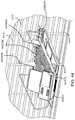
- base 1540may also include tracks 1649 A, 1649 B into which mounting brackets 1690 A, 1690 B can be fit.
- Mounting brackets 1690 A, 1690 Bare slid into tracks 1649 A, 1649 B to mount system 830 on a wire grid system 2410 in the back of a case 2420 .
- grid system 2410includes a plurality of horizontal 2412 and vertical 2414 bars.
- Each mounting bracket 1690 A, 1690 Bincludes one or more hooks 1592 located, when assembled, near the rear edge 1545 of base 1540 . Hooks 1592 hook over horizontal bars 2412 of the grid system 2410 to mount the system 830 in place on the grid 2410 .
- Base 1540may include additional tracks 1649 A, 1649 B to accommodate additional mounting brackets 1690 A, 1690 B for mounting the system 830 .
- Each mounting bracket 1690 A, 1690 Bcould also include additional hooks 1592 for hooking the mounting brackets 1690 A, 1690 B onto the grid system 2410 .
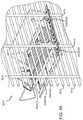
- system 830may also include adjustable side arms 1680 and 1682 to accommodate different sized products.
- Arms 1680 , 1682are adjustable to contain various sizes of products so that the products do not fall off the tray 860 over the side of the system 830 .
- Arms 1680 , 1682are movable in the directions indicated by arrows E 1 , such that they can be positioned nearer the tray 860 and away from the tray 860 .
- arms 1680 , 1682are coupled to the tray 860 by flexible tabs 1484 A, 1484 B, 1486 A, 1486 B at the edges of each arm 1480 , 1482 .
- Tabs 1484 A, 1484 B, 1486 A, 1486 Bfit into slots 1465 near the front edge 1463 of and rear edge 1464 of tray 860 .
- tabs 1484 A, 1484 B, 1486 A, 1486 Bare fit into the centermost slots 1465 of the tray.
- a usercan pull outward on the arms 1480 , 1482 until the tabs 1484 A, 1484 B, 1486 A, 1486 B loosen from the slots 1465 .
- tabs 1484 A, 1484 B, 1486 A, 1486 Bfit into the appropriate slots 1465 to secure that arms 1480 , 1482 at the desired expanded position.
- Other means of moving and securing the arms 1480 , 1482may be used.
- side railsmay be used in place of arms 1480 , 1482 .
- Stationary side armsmay also be used in lieu of movable arms 1480 , 1482 .
- Arms 1480 , 1482may also include vents 1488 to allow the cool air to easily travel to the front of the case 2420 .
- support arms 1689may be coupled to base 1640 to provide added stability to the arms 1680 , 1682 in their extended position.
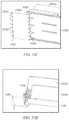
- Front plate 18100also includes a front plate 18100 .
- Front plate 18100is aligned with the front edge 1263 of tray 860 as seen in FIGS. 18-19 .
- the front plate 18100acts as a product stop so that products do not fall over the front edge 1263 of the tray 860 .
- Front plate 18100is coupled to the separator 2050 by a lip 20101 extending from front plate 18100 that fits into recesses 2056 on bottom of separator 2050 (see FIGS. 10, 20 ).
- snap-fit tabs 50107 bcan be used to fit the lip 20101 into recesses 1056 .
- front plate 15100has a curved shape. This shape provides several advantages over traditional flat front plates.
- the bottom curvature 15102gives a bigger footprint to the bottom of the bags to help in keeping the bags upright on the tray 860 .
- the top curvature 15104both helps to keep bagged products upright, and also, with any shape of product used with the system 830 , makes removal of products easier as the products easily slide over the top curvature 15104 for smooth removal from the tray 860 (as opposed to traditional flat plates, which have a blunt straight top edge that can make pulling products over the edge difficult).
- front plate 19100also provides a display surface on which indicia such as graphics, information, labels, tags or bar codes can be placed.
- front plate 19100includes two label holders 19106 , 19108 .
- First label holder 19106is sized to fit standard-sized price tags.
- the second label holder 19108includes two protrusions 19108 A, 19108 B to form the top and bottom walls of the label holder 19108 . Because no side barriers are included, second label holder 19108 can accommodate non-traditional sized tags or labels.
- Second label holder 19108could also be formed by including differently-sized or shaped protrusions 19108 A, 19108 B and/or spacing the protrusions 19108 A, 19108 B further apart or closer together to accommodate various types and sizes of labels or tags.
- Front plate 19100further includes vents 19109 . As seen in FIGS. 18 and 24 , vents 18109 allow cool air which enters at the rear of the system 830 to flow through and out of the front of the system 830 through the vents 18109 (indicated by arrow A 1 ).
- FIGS. 49A and 49Bshow another embodiment of a front plate.
- the front plate 49100 aincludes an adapter plate 49111 a and coupler plate 49113 a .
- the coupler plate 49113 acan be coupled to the separator 2050 as described with respect to front plate 18100 .
- the adaptor plate 49111 acan be removably coupled to the coupler plate 49113 a via channels 49115 a for quick and easy assembly, removal and replacement of the adapter plate 49111 a .
- front plate 49100 acan also include vents 49109 a and label holders 49108 a .
- FIGS. 50A and 50BAnother embodiment of a front plate is shown in FIGS. 50A and 50B .
- front plate 50100 bis curved and includes vents 50109 a and lip 50101 b .
- Front plate 50100 bincludes a curved label holder 50106 a , and a short section 50117 b .
- FIG. 50Balso shows snap-fit tabs 50107 b that can be used to fit any front plate of the present invention to recesses 2056 on the bottom of separator 2050 .
- FIGS. 51A and 51BYet another embodiment of a front plate is shown in FIGS. 51A and 51B .
- front plate 51100 cincludes a curved label holder 51106 c , vents 51109 c and lip 51101 c.
- System 830can also include one or more plenum plates 8110 A, 8110 B.
- Each plenum plate 8110has a plurality of fingers 8112 .
- plenum plates 22110 A, 22110 Bare attached to base by channels 2249 A, 2249 B molded into the rear edge 1145 of base 1140 .
- Plenum plates 22110 A, 22110 Bare also adjustable. To adjust plenum plates 22110 A, 22110 B a user can slide the plates 22110 A, 22110 B toward ( 22 A) or away from ( 22 B, 22 C) the center of the base 1140 in the channels 2249 A, 2249 B.
- Plenum plates 8110 A, 8110 Bcan be adjusted to align with the positioning of the adjustable arms 880 , 882 , and adjustment also allows alignment of slits 8114 between fingers 8112 with the vertical grid wires 2014 .
- fingers 8112are placed between the vertical grid wires 2414 and pushed through, so that vertical grid wires 2414 slide through slits 8114 and into voids 8116 in the plenum plates 8110 A, 8110 B and system 830 is snap-fit onto the grid system 2410 . As seen in FIGS.
- the fingers 8112act to capture cold air which would otherwise drop behind the products (as shown by the lines C 3 ) and guide the cold air into the gap 2344 in the system 830 (shown by the arrow A 1 ) to promote better cooling of the products displayed on the system 830 .
- FIGS. 47A, 47B and 48show one embodiment of system 830 without plenum plates. While the plenum plates are effective to direct cold air into the gap 944 , the placement of the fingers between the vertical grid wires 2014 can be an extra step in the installation process that merchandisers may want to avoid. Without the plenum plates, cold air still flows into gap 944 to sufficiently circulate cold air beneath the products. For these reasons, merchandisers may prefer the system 830 without plenum plates.
- cold airis pumped into the case 2420 at the front side of the case in the direction indicated by the arrow C 1 .
- the cold airthen circulates around the bottom of the case 2420 and upward toward the top of the case 2420 along the back wall of the case 2420 , as indicated by the arrow C 2 .
- the cold airNormally, as shown by the dotted line C 3 , the cold air then falls to the bottom of the case 2420 behind the products, meaning cold air is not directed to the products themselves.
- the response to the issueis often to increase the amount of cold air pumped into the case 2420 to decrease the overall air temperature in the entire case 2420 .
- bafflesare sometimes placed between traditional display systems within the case to attempt to stop cold air from falling behind the products and directing it to the products on the shelves.
- the bafflespresent a host of disadvantages to the retailer, consumer, and, because of imprecise placement in the case, often fail to sufficiently direct the cold air to the products on the shelves.
- the current system 830solves these problems by allowing proper cooling of the products through capturing of the falling cold air (C 3 ) and circulation under the products (A 1 ) in one easy-to-install, versatile, space-saving system 830 . Ventilation of the system 830 works as follows. As seen best in FIGS. 9A-9B and 24 , the assembled system 830 includes a gap 944 between the base member 940 and the separator 1150 , allowing cold air to pass through the gap 944 and beneath the products displayed on the system 830 .
- the fingers 8112 of the plenum plates 8110 A, 8110 Bhelp capture the falling cold air (C 3 ) and direct it into the back of the system 830 , above the rear edge 945 of the base 940 , and through the gap 944 beneath the products displayed on the system 830 .
- the cold airthen exits the front of the system 930 through the vents 18109 in the front plate 18100 aligned with the gap 944 .
- This airflow through the systemis indicated by arrows A 1 .
- the self-ventilating system 830by eliminating the need for baffles, allows retailers to increase the number of systems 830 in a case by placing them closer together and without space-wasting baffles in between. Also, as seen in FIGS. 25A-B and 26 , systems 830 do not have to be linearly aligned across the case to accommodate baffles, and as such a retailer has more freedom to vary the number and types of systems 830 and products within a case 2420 .
- the system 830includes a base member 27400 , separator portion 28500 and tray 27600 .
- the separator portion 28500is stationary and does not slidably connect to the base member 27400 .
- the tray 27600is snap-fit into the separator portion 28500 by inserting shafts 28610 on the bottom of the tray 27600 into holes 28510 in the separator 28500 .
- the separator 28500is sized so that it securely snap-fits into the base 27400 .
- a gap 30440is provided between the base 30400 and the separator 30500 through which air can flow beneath products on the tray 30600 .
- the embodiment in FIGS. 27-35includes adjustable side arms 27800 and 27820 to accommodate different sized products by positioning them nearer the tray 27600 and away from the tray 27600 .
- arms 27800 , 27820are coupled to the tray 27600 by flexible tabs 33840 A, 33840 B, 33860 A, 33860 B at the edges of each arm 27800 , 27820 .
- Tabs 33840 A, 33840 B, 33860 A, 33860 Bfit into slots 28650 near the front and rear edges of tray 27600 .
- tabs 33840 A, 33840 B, 33860 A, 33860 Bare fit into the centermost slots 28650 of the tray.
- a usercan pull outward on the arms 27800 , 27820 until the tabs 33840 A, 33840 B, 33860 A, 33860 B loosen from the slots 28650 .
- tabs 33840 A, 33840 B, 33860 A, 33860 Bfit into the appropriate slots 28650 to secure that arms 27800 , 27820 at the desired expanded position.
- Stationary side armsmay also be used in lieu of movable arms 27800 , 27820 .
- Arms 27800 , 27820may also include vents 33880 to allow the cool air to easily travel to the front of the case 2420 .
- tray 27600includes a generally rectangular opening 27620 that extends along the length of the tray 27600 .
- a pusher plate 27700snap-fits securely into the opening 27620 of the tray 27600 .
- the pusher plate 27700 and a coil spring 28710which fits into a trough 27740 of the pusher plate 27700 , serve as means of biasing products toward the front of the tray 27600 as products are removed from the tray 27600 .
- base 28400may also include tracks 28490 A, 28490 B into which mounting brackets 28900 A, 28900 B can be fit. Mounting brackets 28900 A, 28900 B are slid into tracks 28490 A, 28490 B to mount system 830 on a wire grid system 2410 in the back of a case 2420 as shown in FIG. 24A and described above.
- the embodiment of system 30 in FIGS. 20-28also includes a front plate 1000 .
- Front plate 1000is coupled to the separator 28500 by inserting screws 281010 through holes 28505 in the separator and tightening into holes (not shown) in the front plate 271000 .
- Front plate 271000also has the curved shape and display surface and advantages of these features as described above with respect to the embodiment shown in FIGS. 8-26 .
- Front plate 271000further includes vents 281090 to allow cool air which enters at the rear of the system 830 to flow through and out of the front of the system 830 through the vents 281090 as described above.
- system 830also can include one or more plenum plates 281100 A, 281100 B.
- these plenum plates 281100 A, 281100 Bare the same as those described above with respect to previous embodiments, where each plenum plate 281100 has a plurality of fingers 311120 , and plenum plates 311100 A, 311100 are attached to base 31400 by channels 31495 A, 31459 B molded into the base 31400 .
- Plenum plates 311100 A, 311100 Bare also adjustable and can be adjusted to align with the positioning of the adjustable arms 27800 , 27820 , and adjustment also allows alignment of slits 311140 between fingers 311120 with the vertical grid wires 2414 , where the grid wires 2414 fit in the voids 311160 in the plates 311100 A, 311100 B.
- the fingers 311120act to capture cold air which would otherwise drop behind the products (as shown by the lines C 3 ) and guide the cold air into the gap 31440 in the system 830 (shown by the arrow A 1 ) to promote better cooling of the products displayed on the system 830 .
- the system 830is also effective without the plenum plates.
- FIGS. 27-35fits into the same types of cases 2420 in the same way as described above and has the same features and advantages as described above. It allows proper cooling of the products through circulation of cold air under the products (A 1 ) in one easy-to-install, versatile, space-saving system 830 .
- the fingers 311120 of the plenum plates 311100 A, 311100 Bhelp capture the falling cold air (C 3 ) and direct it into the back of the system 830 , above the rear of the base 31400 , and through the gap 31440 beneath the products displayed on the system 830 .
- the cold airthen exits the front of the system 830 through the vents 281090 in the front plate 271000 aligned with the gap 31440 .
- the foodis more directly cooled than in traditional systems, without the use of baffles.
- FIG. 36Bshows one example of a standard merchandising shelf 362500 to which a baffle system 372000 may be added.
- the shelfmay include a tray 362510 , a pusher plate 362520 , a front plate 362530 , a coil spring 412540 , side arms 362550 A, 362550 B which may be adjustable, and mounting brackets 362560 A, 362560 B.
- baffle system 372000Other configurations of merchandising systems with additional or modified components may also be used with a baffle system 372000 .
- a baffle system 372000By fitting a standard shelf 362500 with a baffle system 372000 as shown in FIG. 36A , cooling of the products on the shelf 362500 by directing cold air through the baffle system 372000 beneath the products may be accomplished without the need to purchase an entirely new self-ventilating merchandising system.
- baffle system 372000includes baffle base 372020 , baffle wings 372030 A, 372030 B, wing extensions 372040 A, 372040 B, and plenum plates 372050 A, 372050 B.
- Baffle base 372020snap-fits onto the merchandising shelf 362500 , and as seen in FIGS. 36A and 40-46 , assembled baffle system 372000 works to direct air from the back of the cooler beneath products on the shelf 362500 to provide direct cooling to the products.
- Baffle base 372020includes slots 372025 into which plenum plates 372050 A, 372050 B can be slidably fit and allows slidable adjustment of the plenum plates 372050 A, 372050 B.
- Baffle wings 372030 A, 372030 Bsnap-fit onto baffle base 372020 .
- openings 382032 in wings 382030 A, 382030 Bare used to movably attach wing extensions 382040 A, 382040 B to each wing 382030 A, 382030 B.
- Tabs 382042 on the wing extensions 382040 A, 382040 Bfriction fit into the openings to allow wing extensions 382040 A, 382040 B to slide toward and away from the center of the baffle base 382020 .
- wing extensions 382040 A, 382040 Bcan be adjusted to accommodate larger products which extend beyond the tray 362510 and are held in place by extendable side arms 362550 A, 362550 B and ensure that cold air directed by the plenum plates 372050 A, 372050 B (also adjustable to line up with larger products extending beyond the tray 362510 ) is directed beneath the entire product area.
- plenum plates 372050 A, 372050 B, wing extensions 372040 A, 372040 B and arms 362550 A, 362550 B of the shelf 362500can all be adjusted to accommodate products of varying sizes to ensure that cold air is properly directed beneath the products.
- Wing extensions 372040 A, 372040 Bmay also include vents 372045 to allow further circulation of cold air beneath products on the tray 362510 above.
- baffle base 372020includes a gap 372010 .
- the plenum plates 372050 A, 372050 B in this embodimentcapture the falling cold air (C 3 ) and direct it into the back of the system 830 , through the gap 372010 beneath the products displayed on the merchandising shelf 362500 .
- C 3falling cold air
- the fingers 382054 of the plenum plates 372050 A, 372050 Bact to capture cold air which would otherwise drop behind the products (as shown by the lines C 3 ) and guide the cold air into the gap 372010 in the system 830 (shown by the arrow A 1 ) to promote better cooling of the products displayed on the system 830 .
- the foodis more directly cooled than in traditional systems.
- 43-49are adjustable, and adjustment allows alignment of slits 382052 between fingers 382054 with the vertical grid wires 2414 , where the grid wires 2414 fit in the voids 382056 in the plates 382050 A, 382050 B.
- plenum plates 382050 A, 382050 Bare adjusted to accommodate products of varying sizes on the shelf 362500 , the slits 382052 , fingers 382054 , and voids 382056 ensure that the system 830 can be attached to a grid.
- any of these embodimentsmay be provided in a shelf-mounted version.
- various shelf-mounting accessorieswill now be discussed which may be used in connection with any one of the above-identified embodiments and/or which may be combined with one or more features from any or all of the above-identified embodiments to come-up with even more embodiments.
- FIGS. 52A-FAn exemplary embodiment of such a shelf-mounting accessory is illustrated in FIGS. 52A-F , which shows the accessory connected to a pull-out tray similar to the one illustrated in FIGS. 8-51B in order to make a shelf-mounted version of the tray.
- the shelf-mounted tray assemblyis referred to generally by reference numeral 52100 and includes a base 52110 , a tray 52120 movably connected to base 52110 and having adjustable width left and right wings 52122 a and 52122 b , respectively, pusher assembly or paddle 52130 to front face the products disposed in the product channel of tray 52120 via a spring (not shown) like the embodiments discussed above, and a front fence or lens 52140 .
- the tray assembly 52100further includes a shelf-mounting accessory that can be coupled to the tray assembly 52100 to allow the tray assembly 52100 to be mounted to a conventional retail store shelf or shelving unit.
- the shelf-mounting accessoryincludes a first spacer, such as first riser 52160 and an end bracket 52180 .
- the riser 52160is used to provide space below the tray assembly 52100 so as to access the tray actuator or release button 52120 a .
- This spacingalso forms an air channel below the merchandiser 52100 which can assist air circulating over or through the shelving unit to keep all of the product stored within the product channel between the left and right wings 52122 a , 52122 b , respectively, more uniformly cooled or chilled and preventing just the products on either end of the product channel from staying cool as compared to the remainder of the products in the product channel.
- the gap created between the tray assembly 52100 and the upper surface of the shelf via first riser 52160serves as a baffle or air duct to promote proper circulation of air when the unit 52100 is used in a refrigerated or cooled/chilled setting or environment (e.g., such as in an open-air cooler).
- the riser 52160is a molded plastic part that has at least two legs extending down from opposite sides of the tray (generally below the left wing 52122 a and right wing 52122 b , respectively, at least when the wings are in their narrow most setting).
- the riser 52160will include four legs extending down from opposite corners of the riser 52160 in order to provide greater structure strength and stability to the riser 52160 and tray assembly 52100 .
- the riseris configured with mating recesses located on opposite sides of the riser 52160 that receive the male mating members existing on the tray assembly 52100 , best seen in FIGS. 52E-F .
- the left male mating member 52110 ais a hook or prong that is deformable and capable of moving between a first normally biased position and a second flexed position to allow a solid portion of riser 52160 to pass inside of the male member 52110 a , but once the hook of the male member 52110 a is aligned with the recess formed in the side of the riser 52160 , the male mating member moves back towards its first normally biased position to engage the riser 52160 and secure it to the base 52110 .
- a similar male mating memberis located on the right side of the base 52110 and a similar recess is located on the right side of the riser 52160 , however, these are not visible in the illustrations shown in FIGS. 52A-F .
- the riser 52160will take the form of riser 63160 in FIG. 63 .
- the riserhas four legs 63160 a , 63160 b , 63160 c and 63160 d (e.g., left front leg, left rear leg, right rear leg and right front leg, respectively), which extend down from opposite sides 63160 e , 63160 f of a main body member 63160 g .
- the sides 63160 e and 63160 ffurther define the above-mentioned recesses in the upper portion thereof for receiving the male mating member 52110 a from base 52110 .
- Riser 63160is preferably made of an injection molded plastic and, thus, has a design that is easier to mold (e.g., rounded edges or gentle curves instead of sharp edges, tapering or draft to assist in removal from mold, etc.).
- the shelf mounting accessory of assembly 52100 in FIGS. 52A-Ffurther includes a rear member, such as bracket 52180 , which extends from a rear of the tray assembly 52100 and secures the tray assembly 52100 to a rear portion of the shelf the tray assembly 52100 is mounted on.
- the bracket 52180both secures the tray assembly 52100 to the rear of the shelf and serves to space the rear of the tray assembly 52100 from the upper surface of the shelf (such as riser 52160 does for the forward portion of the tray assembly 52100 ).
- the bracket 52180includes a mating member 52180 a for mating the bracket 52180 to the rear of the base 52110 of tray assembly 52100 .
- the bracket 52180extends down from the mating member 52180 a and forms a shelf 52180 b . From there the bracket extends down again to form a spacer portion 52180 c and a shelf engaging portion or foot 52180 d that extends back toward the rear portion of the shelf. The bracket 52180 then extends down again to form a rear portion or rear bracket portion 52180 e of bracket 52180 and bends back forward to form a return portion 52180 f . Together the foot 52180 d , end portion 52180 e and return portion 52180 f form a generally U-shaped structure rotated ninety degrees so as to have an open side face which extends around a rear portion of conventional gondola shelving in order to secure the tray assembly 52100 to the shelf or shelf assembly.
- the bracket 52180will take the shape of bracket 53180 illustrated in FIG. 53 .
- the mating structure 53180 ais preferably an inverted U-shaped structure formed from a bend in the bracket 53180 .
- mating structure 53180 aengages a lip formed by a recess at the rear of the tray base 52110 .
- the distal end of mating structure 53180 ais disposed within a channel formed in the rear of base 52110 (similar to the channels discussed above and illustrated in FIGS. 22A-C above, e.g., 2249 A and 2249 B).
- the bracket 53180then bends forward to form shelf 53180 b , down to form riser portion 53180 c , back to form foot 53180 d , down to form rear portion 53180 e and back forward to form return portion 53180 f.
- FIGS. 54A-EAn alternate tray assembly embodiment 54100 is illustrated in FIGS. 54A-E , which includes many of the same features as tray assembly 52100 , including having a base 54110 , tray 54120 movable about the base 54110 , a pusher 54130 for front facing product in the product channel defined by left wing 54122 a and right wing 54122 b , and a lens or fence 54140 .
- the tray assembly 54100further includes a riser 54160 that is similar to riser 52160 discussed above, however, unlike the embodiment of FIGS. 52A-F , tray assembly 54100 includes an alternate rear bracket 54180 .
- bracket 54180is made of an injection molded plastic instead of a metal and includes a smaller return portion 54180 f that has a non-linear edge (e.g., as illustrated the return is comprised of a plurality of rounded tabs).
- a return portion 54180 fthat has a non-linear edge (e.g., as illustrated the return is comprised of a plurality of rounded tabs).
- the tray assembly 55100includes a base 55110 , tray 55120 movable about the base (e.g., extensible or extendible along the base) with left and right wings, 55122 a , 55122 b , respectively, a pusher 55130 and lens or fence 55140 .
- the shelf mounting accessoryincludes a first riser 55160 and a second riser 55170 .
- the second riser 55170is connected to mating structures on the base 55110 similar to how the first riser 55160 is connected to base 55110 (e.g., male protrusion or mating hook member 55110 a ).
- second riser 55170includes first and second recesses on opposite sides of the riser 55170 that mate with mating members on opposite sides of base 55110 . Since only the left side is visible, only mating structures 55110 a and 55110 c are illustrated.
- the shelf mounting accessoryfurther includes a bracket 55180 which is connected to the second riser 55170 .
- the bracket 55180is connected to the second riser 55170 via a fastener (e.g., screw, bolt, rivet, adhesive, hook and loop structures, etc.), however, in alternate forms, it should be understood that the second riser 55170 and bracket 55180 could be formed as an integral structure.
- a fastenere.g., screw, bolt, rivet, adhesive, hook and loop structures, etc.
- the bracket 55180does not extend beyond the rear of the tray assembly 55100 . This may be desirable in some situations where a short or non-deep shelf is to be connected to and it is desired for the merchandiser 55100 to extend beyond the rear of the shelf to increase the amount of product that may be displayed in each product channel. In alternate embodiments, however, there may not be sufficient space for the tray assembly 55100 to extend beyond the rear of the shelf to which it is connected. Thus, in such instances, the tray assembly may be configured as is illustrated in FIGS. 52A-F or in the alternate embodiment illustrated in FIGS. 56A-B in which the bracket extends beyond the back of the tray assembly 52100 and 56100 , respectively.
- the second riser 56170could be integrally formed with the bracket 56180 or it could be fastened thereto as is illustrated in FIGS. 56A-B .
- internally threaded boresare illustrated as being formed in or proximate the legs 56170 a - d of riser 56170 .
- the shelf and vertical upright to which is connectstypically have a gap therebetween which allows sufficient space for placing the rear brackets discussed herein.
- An example of this gapis illustrated in the conventional shelving unit illustrated in FIGS. 57A-B , with the shelf identified by reference numeral 5790 and the vertical upright identified by reference numeral 5792 .
- One problem with having such a gapis that it provides space for the tray assembly to move with respect to the shelving unit (e.g., the shelf itself, the vertical upright, or both). In particular, this gap can result in the tray assembly being movable back and forth laterally (or yaw) as well as pivotally along a horizontal axis (or pitch).
- the bracket 58180includes a movable spacer plate 58180 g which is movable toward and away from the bracket 58180 . In practice, this spacer plate may be extended out away from the bracket 58180 to fill the gap illustrated in FIG. 57B to prevent such unwanted movement. Once the spacer plate is positioned in the desired position, it can be fastened to bracket 58180 via fasteners 58180 h . In the form illustrated, the spacer plate 58180 g and bracket 58180 operate as a spreader to spread apart from one another and exert force on the rear edge of the shelf and the forward edge of the vertical upright.
- FIGS. 59A-EYet another embodiment for securing the rear bracket to the shelving unit is illustrated in FIGS. 59A-E .
- the bracket 59180includes a clamp member 59180 i and a cam actuator 59180 j for moving the clamp member 59180 i between limits of travel.
- the clamp 59180 i and cam actuator 59180 jare situated to cause a clamping effect between the upper and lower surfaces of the shelf.
- the cam operator or actuator 59180 jmay be moved to exert a clamping force on the shelf with clamp member or jaw member 59180 i .
- a similar configurationcould be used to cause a clamping force between the rear edge of the shelf and the rear of the tray assembly (instead of the top and bottom surfaces of the shelf).
- FIGS. 60 and 61Two additional alternative embodiments of rear brackets are illustrated in FIGS. 60 and 61 .
- the rear bracket 60180has an alternate mating member 68180 a that has a plurality of male protrusions that mate with existing female recesses located on the bottom surface of the base of a tray assembly.
- bracket 68180 ainstead of bending downward over a wall of the rear of the tray assembly base like with prior embodiments, bracket 68180 a simply gets inserted into the bottom of the base and forms a riser portion 68180 c , foot portion 68180 d , rear portion 68180 e and return portion 68180 f .
- the return portion 68180 fis removable and repositionable on the vertical portion 68180 e so that the return portion 68180 f can be adjusted to different depths to accommodate shelves of different thickness. This allows the bracket 68180 to be more securely attached to the shelf (or more customizable to the specific shelf it is attached to).
- the return portion 68180 fmates with the vertical rear portion 68180 e via a dove-tail configuration (mortise & tenon configuration), but other interlocking arrangements or connectors may be used to form this connection.
- the bracket 61180has a similar mating relationship between the return portion 68180 f and the vertical rear portion 68180 e , however, in this form, the mating portion 68180 a takes on a different shape and is preferably configured to slide on from the side of the tray assembly at its rear. In the form illustrated, the mating portion 68180 a forms a mortis and the rear of the tray assembly will have a corresponding tenon for connecting the bracket 68180 to the tray assembly.
- FIGS. 62A-Can alternate mechanism for spacing the tray assembly up off of the shelf surface is illustrated using metal support arms very similar to those already used on conventional trays to mount same to bars or grids, however, in the form illustrated, the metal support arms simply perform a riser function and a rear bracket function for securing the tray to the shelving unit.
- a metal blanksuch as that illustrated in FIG. 62C may be formed via stamping, pressing, casting or the like and then bent into the configuration illustrated in FIGS. 62A-B .
- the structureis formed into an integral structure having left arm 62150 a , right arm 62150 b and rear bracket 62180 .
- FIGS. 64, 65, 66, 67 and 68A -B and 72Alternate riser shapes are illustrated in FIGS. 64, 65, 66, 67 and 68A -B and 72 .
- FIG. 64an alternate bent metal riser is shown and referred to generally as riser 64160 . In alternate forms, this too could be made of molded plastic, if desired.
- FIG. 65Another metal riser is illustrated in FIG. 65 and referred to generally as riser 65160 .
- riser 65160does not define recesses or openings for receiving the mating male projection of the tray assembly base, but rather simply bends distal ends of the riser 65160 back over itself (e.g., upon itself) in order to create a downward facing ledge, shelf or shoulder 65160 h that the mating male projection can engage to secure the riser 65160 to the base of the tray assembly.
- this same general designcould be produced via a plastic molding process if it is desired to make the riser 65160 out of plastic.
- the moldwould simply be designed with this step or ledge in there to form a gripping or engaging surface 65160 h for the tray assembly's mating male member to engage.
- Some benefits to using bent metal as the riseris that it can be formed with sharper corners, such as the one illustrated in FIG. 66 , and is more resistant to fatigue overtime if the riser is attached and removed from the tray assembly repeatedly over its lifetime (which is not likely). Since any bend can weaken metal at that location, the corner can be reinforced or bolstered via a support such as the buttresses illustrated in FIG. 67 . However, such a design is better suited for a plastic molded version of the riser if it is determined such support is needed (e.g., due to the weight of the goods to be supported by the tray merchandiser).
- FIGS. 68A-Banother attachment mechanism is illustrated in the embodiment of FIGS. 68A-B , which has a protrusion 68160 i extending from one or more of the legs of the riser 68160 which can be used to connect the riser 68160 to a conventional rail structure like that illustrated in FIGS. 69A-C in order to secure the riser (and thus the tray assembly) in position on the shelf via the rail.
- FIG. 69Aa conventional retail store gondola upright 69192 and shelf 69190 system are illustrated, showing how such shelving units typically include openings 69190 a spaced at regular intervals along at least the front and rear boundary of the shelf (normally in a plurality of rows at the front and rear portions of the shelf).
- the above-mentioned shelf management systemstypically have front and/or rear rails that are connected to the shelf using the front and/or rear holes 69190 a in the shelving surface, respectively.
- An enlarged view of the gondola shelving systemis shown in FIG. 69B and, in the form illustrated, the rail 69194 defines openings 69194 a that fasteners, such as friction-fit or press-fit pins are inserted into to secure the rail 69194 to the front of the shelf 69190 using the openings 69190 a that exist in the shelving surface.
- the railmay have projections extending from the bottom surface thereof that are designed to friction-fit or press-fit into the existing openings in the shelf surface (e.g., press-fit dowels, etc.).
- the rail 69194may be connected to the shelf via other fasteners, such as adhesive, hook and loop structures, magnets, etc.
- a benefit of the rail assemblyis that the tray assembly may be tilted forward, thereby tilting the riser 69160 forward (see FIG. 69C ) in order to allow it to be moved laterally within the channel defined by the rail assembly (without full removal from the rail 69194 ) and then rested back down on the shelf 69190 to fully engage the rail assembly 69194 more securely and prevent unintentional lateral movement of the tray assembly.
- Such a configuration allowing for easy intentional lateral movement of the traysmay be desirable for re-planograming a display and/or inserting cut-ins into a display. Additional frictional members, surfaces and/or materials 70194 a , 71194 a can be added to the rail as illustrated in FIGS.
- FIG. 72illustrates an alternate riser 72160 that engages a rail assembly like those discussed above in similar fashion. More particularly, the protrusion 72160 i extending from the riser 72160 engages with the rail to secure the tray assembly into a desired position on the shelf of a conventional retail store shelving system.
- riser 72160is formed with gentle curves in order to more easily be molded via a plastic molding process.
- shelf mounting accessorieshave been disclosed that allow for trays to be retrofitted to mount to a shelf without requiring changes to the tray.
- the shelf mounting accessoriesinclude use of a spacer or riser (e.g., 54160 , 55160 , etc.).
- the accessoriesinclude use of a rear bracket (e.g., 54180 , 55180 , etc.).
- the accessoriesinclude use of one or more risers (e.g., 55160 , 55170 , etc.).
- the accessoriesinclude use of one or more of any of the risers (e.g., 54160 , 55160 , 55170 , etc.) or brackets (e.g., 54180 , 55180 , 56180 , 58180 , etc.).
- alternative mounting memberssuch as metal support arms may be utilized to connect the trays to the shelf.
- metal support armssuch as 62150 a , 62150 b may be used that are very similar to the arms used to mount conventional trays to bars and grids, and connect to the trays in the same manner, but having different configurations to provide adequate spacing for the pull-out tray to operate (e.g., sufficient spacing to allow the tray to move from its first or normal retracted position wherein it front faces product on the shelf to a second extended position where the tray extends from the shelf to make it easier to stock or re-stock the tray with product.
- FIG. 73Aillustrates a product display 73000 having a pair of tray assemblies 73100 a , 73100 b .
- Each tray assembly 73100 a , 73100 bincludes one or more engagement portions 73160 .
- the engagement portions 73160includes protrusions 73160 i .
- the protrusions 73160 iare sized and configured to be received within the channel of a rail 73194 .
- the engagement portions 73160frictionally engage the rail 73194 so as to restrict lateral movement of the tray assemblies 73100 a , 73100 b along the longitudinal axis of the rail 73194 .
- the tray assembly 73100 aincludes a pair of sidewalls 73122 a , 73122 b .
- the sidewalls 73122 a , 73122 bare solid plastic.
- the sidewalls 73122 a , 73122 b along with the product support surface 73123 a of the tray 73120 aform a product channel in which products are displayed.
- One or both of the sidewalls 73122 a , 73122 bare movable between a first retracted position (as shown) and a second extended position relative to the product support surface 73123 a .
- the sidewalls 73122 a , 73122 bMoving one or both of the sidewalls 73122 a , 73122 b to the extended position widens the area in which products are displayed in order to accommodate products of different sizes.
- the sidewalls 73122 a , 73122 bare infinitely adjustable between the full extended and fully retracted position in order to accommodate a wide variety of product sizes.
- a spring biased pusher 73130urges products resting on the product support surface 73123 a forward towards the front end of the tray assembly 73100 a .
- a lens 73140is positioned proximate the front end of the tray assembly 73100 a to act as a product stop to prevent the pusher 73130 from pushing products off of the tray assembly 73100 a .
- the tray assembly 73100 aincludes locking structure for releasably locking the pusher 73130 in a position proximate the rear end of the tray assembly 73100 a . Locking the pusher 73130 aids in restocking of the tray assembly 73100 a .
- a pusher releaseis used to unlock the pusher 73130 .
- the pusher releaseincludes an actuated positioned proximate the front end of the tray assembly 73100 a.
- the tray assembly 73100 bincludes a pair of sidewalls 73122 c , 73122 d and a product support surface 73123 b of the tray 73120 b that form a channel in which products are displayed.
- a spring biased pusher 73130is used to face products within the channel towards a lens 73140 .
- the sidewalls 73122 c , 73122 dare wireframe.
- One or both of the sidewalls 73122 c , 73122 dare movable between a first retracted position (as shown) and a second extended position relative to the product support surface 73123 b .
- the sidewalls 73122 c , 73122 dMoving one or both of the sidewalls 73122 c , 73122 d to the extended position widens the area in which products are displayed in order to accommodate products of different sizes.
- the sidewalls 73122 c , 73122 dare infinitely adjustable between the full extended and fully retracted position in order to accommodate a wide variety of product sizes.
- the tray assemblies 73100 a , 73100 bare rotatable about the engagement portions 73160 between a first, secured position (see tray assembly 73100 b ) and a second, released position (see tray assembly 73100 a ). In both positions, the protrusions 73160 i extend at least partially into the channel of the rail 73194 . In the secured position, the engagement portion 73160 engages the rail 73194 so as to restrict movement therein, as shown in FIG. 73B .
- the rail 73194is engaged by the protrusions 73160 i as well as a rearward facing surface 73160 b , which is defined within a notch on the underside of the engagement portion 73160 , rearward of the protrusions 73160 i .
- the insertion portion 73160 a of the engagement portion 73160is sized to tightly fit between the nose 73194 b and a forward facing surface of the rear wall 73194 c of the channel of the rail 73194 so as to frictionally engage each.
- one or both of the rail 73194 and engagement portion 73160may have high friction materials to further restrict relative movement.
- the rear end of the tray assembly 73100 ais pivoted upward such that the surface 73160 b no longer engages the wall 73194 c .
- Thisenables the protrusion 73160 i to separate from the nose 73194 b so that the tray assembly 73100 a can be moved laterally along the longitudinal axis of the rail 73194 .
- the tray assemblies 73100 a , 73100 bare infinitely adjustable along the length of the rail 73194 allowing the planogram of the product display 73000 to be continuously adjusted to fit different combinations of products.
- the rail 73194includes a plate portion 73194 p that extends rearward of the wall 73194 c .
- the plate portion 73194 pextends along at least a portion of the length of the tray assemblies 73100 a , 73100 b .
- the plate portion 73194 phas a depth giving the rail 73194 a total depth of between 8 inches and 24 inches.
- the plate portion 73194 pincludes interlocking members 73195 a , 73195 b for coupling a plurality of adjacent rails 73194 .
- the interlocking members 73195 a , 73195 balign adjacent rails 73194 such that the channel portions line up to form one continuous channel.
- the plate portion 73194 pincludes a rear stabilizer.
- the rear stabilizerincludes one or more recesses or apertures into which a projection or protrusion of the tray assemblies 73100 a , 73100 b is received when the tray assemblies 73100 a , 73100 b is in a secured position.
- the rail 73194includes structure for coupling to the top surface of a shelf.
- Exemplary structureincludes adhesive, adhesive strips, high friction materials, magnets, apertures for receiving bolts, screws, or lugs, clamps, or combinations thereof.
- the tray assemblies 73100 a , 73100 bare extendable to aid in restocking. To extend, the product support surface 73123 a , 73123 b slides forward relative to the engagement portions 73160 from a retracted, display position (as shown) to an extended stocking position.
- the tray assemblies 73100 a , 73100 bmay include a tray actuator or release button, such as the release button 52120 a described above.
- the product support surfaces 73123 a , 73123 bmay be rotatable about a vertical axis relative to the engagement portion 73160 . Rotating the product support surfaces provides side access or rear access to the product display channel during restocking.
- the engagement portions 73160are separate components from the trays 73120 a , 73120 b .
- the engagement portions 73160are optional or auxiliary components of the tray assemblies 73100 a , 73100 b .
- the same trays 73120 a , 73120 bcan be utilized in a plurality of tray assemblies configured to attach to different types of shelf units.
- the engagement portions 73160are attached to the trays 73120 a , 73120 b configured to attach to the top surface of a shelf.
- the engagement portion 73160includes one or more protrusions configured to be received within recesses or apertures in the trays 73120 a , 73120 b and/or lens 73140 .
- the protrusionsform a snap fit with the trays 73120 a , 73120 b .
- the engagement portion 73160includes one or more recesses or apertures configured to receive protrusions of the trays 73120 a , 73120 b and/or lens 73140 .
- the attachmentis detachable.
- the engagement portion 73160cannot be detached from the tray assemblies 73100 a , 73100 b without breaking the engagement portion 73160 , tray 73120 a/b , or lens 73140 .
- the attachment structure of the engagement portion 73160may be configured to cooperate with structure of existing trays or lenses so as to retrofit existing tray assemblies for mounting to shelf top rails 73194 .
- FIG. 74illustrates a tray assembly 74100 having an integral engagement portion 74160 .
- the engagement portion 74160includes a forward protrusion 74160 i sized and configured to be received within a rail, such as the rail 73194 described above.
- the tray assembly 74100further includes a pair of opposing sidewalls 74122 a , 74122 b and a tray 74120 having a product support surface 74123 .
- the sidewalls 74122 a , 74122 b and product support surface 74123define a channel in which products are displayed.
- a pusher 74130is spring biased to face products towards a front lens 74140 .
- one or both sidewalls 74122 a , 74122 bare infinitely adjustable relative to the tray 74120 between a fully retracted position and a fully extended position to adjust the width of the product display channel.
- FIG. 75illustrates a product display 75000 having a product support 75123 having an integral engagement portion 75160 and a separate divider 75122 having an integral engagement portion 75160 .
- the engagement portions 75160are substantially similar to the engagement portions described above, having a protrusion 75160 i sized and configured to be received in and engage with a shelf top rail.
- the divider 75122includes a pair of product support surfaces 75122 b , 75122 c disposed on either side of a wall 75122 a . Products span the distance between the support surface 75122 c and the product support 75123 so as to be supported by both.
- the divider 75122is movable independently of the product support 75123 so as to infinitely adjust the width of the product channel formed thereby.
- the product support 75123includes an integral pusher track 75123 a along which a spring biased pusher 75130 travels.
- the product support 75123 and divider 75122each have a downward protrusion (not shown) configured to cooperate with the rear stabilizer of the rail.
- FIGS. 76A-76Eillustrate a product display 76000 .
- the product display 76000includes a tray assembly 76100 having a tray 76120 with a product display surface 76123 .
- the tray 76120is configured to receive a pair of opposing sidewalls and a spring biased pusher, such as those shown above.
- the sidewalls and pusherhave been removed from this embodiment to more clearly show the attachment structure between the tray 76120 , lens 76140 , and engagement portion 76160 .
- the product display 76000further includes a rail 76194 .
- the rail 76194includes a front channel defined by a front nose 76194 b and wall 76194 c .
- a plate portion 76194 p with interlocking members 76195 b , 76195 aextends rearward from the wall 76194 c .
- Proximate the rear end of the rail 76194is a rear stabilizer 76196 .
- the rear stabilizer 76196comprises a plurality of slots 76196 a configured to receive downward protrusions of the tray 76120 .
- the rail 76194has a depth of at least half the depth of the tray 76120 . In some forms, the rail 79194 has a depth of between 8 inches and 24 inches.
- the downward protrusion of the tray 76120is detachable from or movable relative to the tray 76120 such that trays 76120 can be used with rails 76194 of different depths.
- the protrusionis a set distance from the front end of the tray 76120 such that trays of different lengths are each configured to couple to the same rail 76194 .
- one tray 76194is usable with a plurality of different depth shelves.
- the engagement portion 76160includes an insertion portion 76160 a having a forward protrusion 76160 i .
- the insertion portion 76160 ais sized and configured to be received within the channel of the rail 76194 with the protrusion 76160 i being received within the nose 76194 b.
- the lens 76140 , engagement portion 76160 , and tray 76120are configured to detachably couple via snap fit connections.
- the lenshas one or more rearward extending projections 76142 and one or more downward extending projections 76144 .
- the rearward projections 76142have a rounded bottom surface 76142 a .
- the downward extending projections 76144have an arrow shaped or barb shaped end 76144 a .
- the engagement portion 76160has one or more upward and forward opening apertures 76166 sized and configured to receive the rearward extending projections 76142 .
- the engagement portion 76160further includes one or more upward opening apertures 76168 sized and configured to receive the downward extending projections 76144 .
- the lens 76140is tilted or rotated backwards (the top of the lens 76140 is moved rearward relative to the bottom of the lens 76140 ). With the lens 76140 tilted, the rearward extending projections 76142 are inserted into the corresponding apertures 76166 of the engagement portion. The lens 76140 is then rotated forward about the rearward extending projections 76142 , which causes the downward extending projections 76144 to be inserted into the apertures 76168 . During insertion, the angled or cam surface of the arrow shaped ends 76144 a cooperate with the structure of the engagement portion 76160 defining the apertures 76168 which causes the downward extending projections 76144 to deform.
- the arrow shaped ends 76144 aWhen fully inserted, the arrow shaped ends 76144 a have passed fully through the apertures 76168 , enabling them to resiliently return to their non-deformed shape.
- the arrow shaped ends 76144 a and the adjacent portion of the engagement portion 76160form a snap lock or interference lock securing the lens 76140 in position relative to the engagement portion 76160 .
- the downward extending projections 76144In order to decouple the lens 76140 from the engagement portion 76160 , the downward extending projections 76144 must be deformed out of interference with the engagement portion 76160 such that the lens can be rotated backward to reverse the process described above.
- the engagement portion 76160includes one or more rearward extending projections 76162 and one or more downward extending projections 76164 .
- the rearward projections 76162have a rounded bottom surface 76162 a .
- the downward extending projections 76164have an arrow shaped or barb shaped end 76164 a .
- the tray 76120has one or more upward and/or forward opening apertures 76126 sized and configured to receive the rearward extending projections 76162 .
- the tray 76120further includes one or more upward opening apertures 76128 sized and configured to receive the downward extending projections 76164 .
- the engagement portion 76160is tilted or rotated backwards. With the engagement portion 76160 tilted, the rearward extending projections 76162 are inserted into the corresponding apertures 76126 of the tray 76120 . The engagement portion 76160 is then rotated forward about the rearward extending projections 76162 , which causes the downward extending projections 76164 to be inserted into the apertures 76128 . During insertion, the angled or cam surface of the arrow shaped ends 76164 a cooperate with the structure of the tray 76120 defining the apertures 76128 which causes the downward extending projections 76164 to deform.
- the arrow shaped ends 76164 aWhen fully inserted, the arrow shaped ends 76164 a have passed fully through the apertures 76128 , enabling them to resiliently return to their non-deformed shape.
- the arrow shaped ends 76164 a and the adjacent portion of the tray 76120form a snap lock or interference lock securing the engagement portion 76160 in position relative to the tray 76120 .
- the downward extending projections 76164In order to decouple the engagement portion 76160 from the tray 76120 , the downward extending projections 76164 must be deformed out of interference with the tray 76120 such that the engagement portion can be rotated backward to reverse the process described above.
- FIGS. 76A-76Eillustrate a display in which projections of the lens are inserted into the engagement portion and projections of the engagement portion are inserted into the tray
- the lens and engagement portionmay each have projections similar to those described above which are inserted into corresponding apertures in the tray.
- the position of the apertures and projectionsmay be reversed such that the tray has projections that are inserted into the engagement portion which in turn has projections that are inserted into the lens.
- two structures(such as the engagement portion and tray) are attached to each other using projections on each structure which are inserted into corresponding apertures in the other.
- a tray accessory 76000 for mounting a tray 76120 to a shelfcomprises a first mount 76160 to connect the tray 76120 to a shelf, the first mount having a first mating structure 76162 / 76164 for mating the first mount 76160 to at least a portion of the tray at a front or forward portion of the tray 76120 , and a second mating structure 76160 a for mating the first mount 76160 to the shelf at a front or forward portion of the shelf.
- the first mating structure 76162 / 76164connects onto or is inserted into the front or forward portion of the tray 76120 , and the second mating 76160 a structure comprises a protrusion 76160 i for mating with a corresponding structure 76194 on the front or forward portion of the shelf.
- the second mating structure 76160 aindirectly mates the first mount 76160 to the shelf via an interconnecting member 76194 .
- the interconnecting member 76194includes a rail or channel that the protrusion 76160 i of the second mating structure connects to.
- the interconnecting member 76194forms a base that may be fastened to the shelf via a fastener including at least one of an adhesive, magnet, pin, bolt, screw or rivet, and the rail or channel formed by the interconnecting member forms an uninterrupted rail or channel that allows for continuous adjustment of the second mating structure along the rail or channel to allow for unlimited positioning over that span.
- the second mountto connect the tray to the shelf, the second mount having a third mating structure for mating the second mount to at least a portion of the tray at a side or intermediate portion of the tray, and a fourth mating structure for mating the second mount to the shelf at an intermediate portion of the shelf.
- the second mountcomprises a structure configured to movably or removably couple to the bottom of the tray.
- the structurehas a downward protrusion for cooperating with the stabilizer 76196 .
- the fourth mating structureindirectly mates the second mount to the shelf via the interconnecting member 76194 and the interconnecting member 76194 defines a fifth mating structure 76196 that mates with the fourth mating structure to connect the tray to the shelf.
- FIGS. 73A-76Edisclose trays having a single product channel. It is understood that the engagement portions described therein can be used with any of the trays described above in the application, such as the tray 100 which has a plurality of product channels.
- the pushers described hereinare shown as one piece, vertical planes.
- the pushersinclude one or more additional portions which are detachable from or movable relative to the pushers to adjust the size of the pushing surface.
- the pusherextends rearward from its engagement point with the tray so as to increase the depth of the product display channel when the pusher is in its rearward most position.
- the lenses described hereinare illuminated to better highlight the products being displayed.
- the product displaysmay include indicators, such as mechanical indicators or electrical indicators like lights, for alerting a user when restocking is required.
- retrofit structures used hereincan connect to existing structures either on the trays themselves (e.g., mating male member 54110 a , 55110 a , etc.) and/or on the shelves themselves (e.g., shelf openings 69190 a , rails 69194 , etc.).
- Some of the accessoriesfurther may be customized or adjusted to fit specific shelves.
- adjustable brackets 58180 , 59180 , 60180 , 61180may all be adjusted to better fit the shelf mounting accessory and tray assembly to a specific shelving unit.
- bracketsare adjustable in height, width, depth and may further mean they exert some form of force on the neighboring structures (e.g., shelf, upright, etc.) in order to secure the tray assembly to the shelf.
- the neighboring structurese.g., shelf, upright, etc.
- clamping forcesare used to secure the tray assembly to the shelf
- spreading forcesare used to secure the tray assembly to the shelf.
- a spacing bracketis used to exert a spreading force and/or to fill a gap between the rear of the shelf and the neighboring upright.
- a cam levermay be operated to exert a clamping force to secure the bracket and tray assembly to a shelving unit.
- Passive connectivitymay be utilized by supplying a rigid bracket that simply loops or hooks around the rear of the shelf.
- Other passive connectivity formsmay include the use of projections or protrusions (e.g., dowels, bench dog, etc.) from the risers, brackets or support arms to simply engage existing structure on the shelves, such as the existing shelf openings or holes.
- active connectivitymay be used by employing the spreader or clamping mechanisms discussed herein, or adding a rail system to the shelf to use such a feature to help connect one or more tray assemblies to the shelf.
- the active connectivity solutionsmay be configured to secure the tray assembly or portions thereof (e.g., bracket, riser, etc.) to a shelf in any of the x, y or z directions (e.g., a vertical clamp, horizontal clamp, vertical spreader, horizontal spreader, etc.).
- a vertical clamp, horizontal clamp, vertical spreader, horizontal spreader, etc.e.g., a vertical clamp, horizontal clamp, vertical spreader, horizontal spreader, etc.
- one or more of any of these points of connectionmay be used to connect the tray assembly to the shelf (e.g., passive only, active only, a combination of both passive and active, etc.).
- thismay include simple insertion of dowels in one area of the tray assembly and assertion of clamping and/or spreading forces in another area of the tray assembly.
- use of features such as a rail connectionmay further allow for more functionality with respect to the trays, such as the ability to perform intentional lateral movement of same for adjustments of the display planogram (e.g., initial setup, replanogram, cut-ins, etc.), and yet still hinder unintentional movement during use or operation of the tray merchandiser.
- the display planograme.g., initial setup, replanogram, cut-ins, etc.
- the embodiments disclosed hereinfurther provide examples for mounting trays to shelving systems using single and multiple points of connection.
- metal support barsmay be used with a rear bracket that offers a single point of connection to the shelf (single point connectivity).
- Other embodimentsuse two point connectivity, such as by using a riser and a rear bracket, two risers, or a riser and an integral riser and rear bracket.
- Yet other embodimentsmay use multi-point connectivity such as by using multiple risers and a rear bracket or other examples in which an adjustable rear bracket may be used to provide itself multiple points of connectivity.
- the trays disclosed hereinmay be integrated with one or more of these features to make them a shelf-mounted specific tray (for example, if it is desired to offer two distinct tray product lines with one targeting shelf-mounted applications and the other targeting bar/grid/upright applications).
- FIGS. 76A-76Emay include features of the tray of FIGS. 1A-1M .
Landscapes
- Display Racks (AREA)
Abstract
Description
Claims (12)
Priority Applications (1)
| Application Number | Priority Date | Filing Date | Title |
|---|---|---|---|
| US16/498,169US11045017B2 (en) | 2017-04-27 | 2018-04-27 | Shelf-mounted tray and methods relating to same |
Applications Claiming Priority (4)
| Application Number | Priority Date | Filing Date | Title |
|---|---|---|---|
| US201762490760P | 2017-04-27 | 2017-04-27 | |
| US201862663147P | 2018-04-26 | 2018-04-26 | |
| US16/498,169US11045017B2 (en) | 2017-04-27 | 2018-04-27 | Shelf-mounted tray and methods relating to same |
| PCT/US2018/029868WO2018200997A1 (en) | 2017-04-27 | 2018-04-27 | Shelf-mounted tray and methods relating to same |
Publications (2)
| Publication Number | Publication Date |
|---|---|
| US20200037784A1 US20200037784A1 (en) | 2020-02-06 |
| US11045017B2true US11045017B2 (en) | 2021-06-29 |
Family
ID=63919181
Family Applications (1)
| Application Number | Title | Priority Date | Filing Date |
|---|---|---|---|
| US16/498,169ActiveUS11045017B2 (en) | 2017-04-27 | 2018-04-27 | Shelf-mounted tray and methods relating to same |
Country Status (3)
| Country | Link |
|---|---|
| US (1) | US11045017B2 (en) |
| CA (1) | CA3058797A1 (en) |
| WO (1) | WO2018200997A1 (en) |
Cited By (8)
| Publication number | Priority date | Publication date | Assignee | Title |
|---|---|---|---|---|
| US20200109001A1 (en)* | 2018-10-03 | 2020-04-09 | Randall Barton Howard | Apparatus and method for holding products |
| USD952381S1 (en)* | 2019-11-08 | 2022-05-24 | Marmon Foodservice Technologies, Inc. | Product display unit |
| USD952380S1 (en)* | 2019-08-26 | 2022-05-24 | Marmon Foodservice Technologies, Inc. | Product display lens |
| US11627819B1 (en)* | 2020-04-09 | 2023-04-18 | Walgreen Co. | Anti-theft system and method for cosmetic products |
| US20240262633A1 (en)* | 2023-02-03 | 2024-08-08 | Fasteners For Retail, Inc. | Selectively securable roller track |
| US20240407571A1 (en)* | 2023-06-06 | 2024-12-12 | Rtc Industries, Inc. | Product management display system with extended pusher travel |
| US12245706B1 (en)* | 2023-09-13 | 2025-03-11 | Fasteners For Retail, Inc. | Pull-out tray for shelving |
| US12251032B2 (en) | 2017-12-01 | 2025-03-18 | Fasteners For Retail, Inc. | Retail merchandise tray |
Families Citing this family (13)
| Publication number | Priority date | Publication date | Assignee | Title |
|---|---|---|---|---|
| US10959540B2 (en) | 2016-12-05 | 2021-03-30 | Retail Space Solutions Llc | Shelf management system, components thereof, and related methods |
| WO2018200997A1 (en) | 2017-04-27 | 2018-11-01 | Retail Space Solutions Llc | Shelf-mounted tray and methods relating to same |
| US10959543B2 (en) | 2018-05-25 | 2021-03-30 | Retail Space Solutions Llc | Tray accessory and tray with mounting structure |
| US11246428B2 (en) | 2018-07-16 | 2022-02-15 | Retail Space Solutions Llc | Product display merchandiser and related methods |
| US10912398B2 (en) | 2019-02-11 | 2021-02-09 | Retail Space Solutions Llc | Adjustable-width pusher tray assembly |
| GB2583775B (en)* | 2019-05-10 | 2023-10-18 | Aerofoil Energy Ltd | Improvements to refrigerators |
| GB2585250B (en) | 2019-07-05 | 2023-11-15 | Aerofoil Energy Ltd | Bracket for use with open display refrigerators |
| US12082717B1 (en) | 2019-08-15 | 2024-09-10 | Aerofoil Energy Limited | Air guide brackets for refrigerators |
| CA3107325C (en)* | 2020-01-29 | 2023-08-22 | Diam Uk Ltd. | Modular pusher and hang display system |
| USD1015769S1 (en) | 2020-01-29 | 2024-02-27 | Diam Uk Ltd. | Product display component |
| US11167883B1 (en)* | 2020-04-29 | 2021-11-09 | Eric Schuldt | Inventory management system |
| KR102796887B1 (en)* | 2023-08-22 | 2025-04-15 | 박주완 | Rack for clothes dryer |
| ES3002085A1 (en)* | 2023-09-01 | 2025-03-06 | Grupo Om Comunicacion Visual S L | DUAL SELF-FACING DEVICE FOR LINEARS (Machine-translation by Google Translate, not legally binding) |
Citations (627)
| Publication number | Priority date | Publication date | Assignee | Title |
|---|---|---|---|---|
| SE76532C1 (en) | ||||
| US153227A (en) | 1874-07-21 | Improvement in self-adjusting book-racks | ||
| US159940A (en) | 1875-02-16 | Improvement in wheels for vehicles | ||
| US431373A (en) | 1890-07-01 | Book and paper rack | ||
| US436704A (en) | 1890-09-16 | Bernard r | ||
| US452673A (en) | 1891-05-19 | Book-support | ||
| US551642A (en) | 1895-12-17 | Combined stamp-holder and ink-pad | ||
| US607890A (en) | 1898-07-26 | Book-support | ||
| US607891A (en) | 1898-07-26 | Sheet-metal book-support | ||
| US632231A (en) | 1898-02-11 | 1899-09-05 | Nat Ticket Case Company | Ticket-case. |
| US808067A (en) | 1904-04-18 | 1905-12-26 | William Cyrus Briggs | Mechanism for feeding cigars to banding mechanisms. |
| US847863A (en) | 1906-04-19 | 1907-03-19 | Thomas A Watts | Vending-machine. |
| US927988A (en) | 1908-10-19 | 1909-07-13 | Thomas C Massey | Vise. |
| US1030317A (en) | 1911-10-26 | 1912-06-25 | Carlisle H Middauge | Separating-case. |
| US1271508A (en) | 1917-03-28 | 1918-07-02 | Lincoln Hall | Label-file. |
| US1282532A (en) | 1918-04-22 | 1918-10-22 | Paul Bochenek | Combined clamp and wrench. |
| US1674582A (en) | 1926-08-09 | 1928-06-19 | Wheeler Jacob | Bookholder |
| US1703987A (en) | 1926-10-25 | 1929-03-05 | Willard A Sloper | Store delivery apparatus |
| US1786392A (en) | 1928-12-10 | 1930-12-23 | Edward F Kemp | Holder for confectionery |
| US1910516A (en) | 1931-10-08 | 1933-05-23 | Paul E Besenberg | Letter and record file and the like |
| US1964597A (en) | 1931-10-09 | 1934-06-26 | Rapellin Rene | Cigarette dispensing device |
| US1971749A (en) | 1931-12-11 | 1934-08-28 | Hamilton Mfg Co | Type case |
| US2013284A (en) | 1932-03-30 | 1935-09-03 | Joseph A Michaud | Sectional automatic display cabinet |
| US2076941A (en) | 1935-01-14 | 1937-04-13 | Revere Copper & Brass Inc | Book end and like supports |
| US2079754A (en) | 1935-07-17 | 1937-05-11 | William V Waxgiser | Article projection apparatus for shelves |
| US2110299A (en) | 1936-11-23 | 1938-03-08 | Hinkle Cecil Edward | Bottle rack |
| US2129122A (en) | 1936-07-10 | 1938-09-06 | Beech Nut Packing Co | Display stand |
| US2218444A (en) | 1938-04-11 | 1940-10-15 | George S Vineyard | Merchandise dispenser |
| US2284849A (en) | 1941-08-29 | 1942-06-02 | Edward P Schreyer | Book end |
| US2308851A (en) | 1940-12-12 | 1943-01-19 | New Monarch Machine & Stamping | Carrier member for display racks |
| US2499088A (en) | 1947-03-29 | 1950-02-28 | Brill | Refrigerated display case |
| US2516122A (en) | 1945-09-20 | 1950-07-25 | Hope Metal Products Co | Metal bin |
| US2538908A (en) | 1948-05-10 | 1951-01-23 | Eugene H Mckeehan | Shelf divider |
| US2555102A (en) | 1948-10-05 | 1951-05-29 | Miner S Anderson | Combined bottle carrier and rack |
| US2652154A (en) | 1949-12-27 | 1953-09-15 | John F Mccarthy | Display rack |
| US2678045A (en) | 1952-04-15 | 1954-05-11 | Frances C Erhard | Card sorting device |
| GB740311A (en) | 1954-01-22 | 1955-11-09 | Albert Weber | A shelf support |
| US2730825A (en) | 1952-02-18 | 1956-01-17 | David L Wilds | Combination rack and price tagging device |
| US2738881A (en) | 1950-04-13 | 1956-03-20 | Michel Gino | Display and storage holder for containers |
| US2750049A (en) | 1954-08-16 | 1956-06-12 | Vendo Co | Vending machine shelf having bottle feeding mechanism |
| US2775365A (en) | 1953-03-06 | 1956-12-25 | Percy W Mestman | Bag dispenser |
| DE969003C (en) | 1952-03-14 | 1958-04-17 | Ver Werkstaetten Wittenau G M | Adjustable shaft for self-sellers |
| US2889907A (en) | 1957-02-18 | 1959-06-09 | Alvey Ferguson Co | Antifriction-type conveyor rail for article storage racks |
| US2893596A (en) | 1953-03-04 | 1959-07-07 | Rowe Mfg Co Inc | Sandwich merchandising machine |
| US2934212A (en) | 1957-12-16 | 1960-04-26 | James J Jacobson | Display and dispensing racks |
| GB881700A (en) | 1959-09-08 | 1961-11-08 | Wilmot Breeden Ltd | Means for dispensing packets or wrapped goods of uniform shape |
| US3083067A (en) | 1960-05-05 | 1963-03-26 | Coopers Inc | Merchandise display and dispensing device |
| US3089675A (en) | 1962-05-23 | 1963-05-14 | Allan G Lozier | Multiple angle shelf bracket |
| US3110402A (en) | 1961-03-29 | 1963-11-12 | Cons Cigar Corp | Adjustable display rack |
| US3121494A (en) | 1961-02-02 | 1964-02-18 | Howard E Berk | Book stop device |
| US3161295A (en) | 1963-01-24 | 1964-12-15 | Chesley Ind Inc | Display device for merchandise |
| US3166195A (en) | 1963-06-25 | 1965-01-19 | Russell E Taber | Display device |
| US3182945A (en) | 1963-08-29 | 1965-05-11 | M & D Store Fixtures Inc | Multi-angle bracket |
| US3248079A (en) | 1963-12-30 | 1966-04-26 | Clark Equipment Co | Angularly adjustable shelf bracket |
| CH412251A (en) | 1964-01-06 | 1966-04-30 | Gemperle Albert | Display and sales shelf with dividing and feeding device |
| US3308961A (en) | 1965-03-03 | 1967-03-14 | Chesley Ind Inc | Package display-dispenser |
| US3339746A (en) | 1965-08-16 | 1967-09-05 | Merlin Mfg Corp | Wall mounted book holder |
| GB1082150A (en) | 1963-12-07 | 1967-09-06 | Acker Norbert Karl | Conveyor of multi-selection vending machines |
| US3405716A (en) | 1967-07-03 | 1968-10-15 | Knoll Associates | Guide rod latch for card file drawer |
| US3452899A (en) | 1967-10-24 | 1969-07-01 | Albert C Libberton | Follower advanced commodity dispenser |
| US3501019A (en) | 1968-07-11 | 1970-03-17 | Armstrong Store Fixture Corp | Means for binning and banding display shelves |
| US3501016A (en) | 1968-02-05 | 1970-03-17 | Kenneth C Eaton | Article storage apparatus |
| US3550979A (en) | 1968-06-20 | 1970-12-29 | Miller Herman Inc | Molded card drawers and cabinets therefor |
| US3587867A (en) | 1969-07-18 | 1971-06-28 | Streater Ind Inc | Base nose hook lock for display stands |
| DE2002720A1 (en) | 1970-01-22 | 1971-07-29 | Matthias Scherer | Compartment, especially for pharmacies |
| DE2011792A1 (en) | 1970-03-12 | 1971-10-21 | Wirz, Hans, Neuhausen, (Schweiz) | Device for the detachable fastening of supports, in particular bookends, to documents |
| US3698568A (en)* | 1970-12-18 | 1972-10-17 | Armstrong Store Fixture Corp | Partition structure with adjustable end member |
| US3751129A (en) | 1971-10-20 | 1973-08-07 | Wright Barry Corp | Card tray |
| DE7311113U (en) | 1973-03-24 | 1973-08-16 | Unternehmensberatung Koch A | Display rack |
| US3776388A (en) | 1971-12-13 | 1973-12-04 | Ethyl Dev Corp | Display tray |
| US3780876A (en) | 1972-01-18 | 1973-12-25 | Lear Siegler Inc | Shelf divider |
| DE2232398A1 (en) | 1972-07-01 | 1974-01-10 | Kurt Baumann | SHOP FACILITIES FOR PACKAGES OF GOODS |
| US3814490A (en) | 1972-10-12 | 1974-06-04 | Wright Barry Corp | File drawer follower block |
| US3815519A (en) | 1973-03-15 | 1974-06-11 | A Meyer | Snap-on adjustable sliding clip for shelf partitions |
| US3832957A (en) | 1972-11-03 | 1974-09-03 | Modern Display Plastics Inc | Interlocking display shelf arrangement |
| US3848745A (en) | 1973-08-08 | 1974-11-19 | J Smith | Tray unit |
| US3868021A (en) | 1973-10-09 | 1975-02-25 | Wilhelm Heinrich | Separator panel holder for display shelves |
| US3873195A (en) | 1973-07-05 | 1975-03-25 | Minnesota Mining & Mfg | Slide tray |
| US3893739A (en) | 1974-10-24 | 1975-07-08 | Gen Motors Corp | Retainer for refrigerator shelf |
| US3949880A (en) | 1975-02-20 | 1976-04-13 | Henschel-Steinau, Inc. | Shelf extender |
| US3960273A (en) | 1975-02-14 | 1976-06-01 | Roy Bernard Weston | Display device |
| US3987384A (en) | 1973-08-06 | 1976-10-19 | Siemens Aktiengesellschaft | Arrangement for coupling an armature to the contact-bridge carrier |
| US4007841A (en) | 1973-02-12 | 1977-02-15 | Oscar Mayer & Co. Inc. | Article display rack |
| US4015886A (en) | 1975-11-03 | 1977-04-05 | Wickenberg Chester H | Storage bins |
| US4042096A (en) | 1976-03-15 | 1977-08-16 | Smith Daniel F | Shelf aid |
| US4084703A (en) | 1977-01-06 | 1978-04-18 | Stein Industries, Inc. | Refrigeration shelf |
| US4106668A (en) | 1977-02-14 | 1978-08-15 | Kayser-Roth Corporation | Device for displaying and storing articles |
| FR2385365A1 (en) | 1977-03-30 | 1978-10-27 | Corjon Jean Louis | Self service display sales unit for cigarettes - has packets pressure pushed forward towards opening by channel guided L-shaped packet sized weights |
| US4168780A (en) | 1978-03-16 | 1979-09-25 | Engineered Products | Flow rail rack |
| DE2825724A1 (en) | 1978-06-12 | 1979-12-13 | Kurt Baumann | Merchandise display unit for upright packages - contains support elements formed from single length of wire |
| GB2027339A (en) | 1978-07-14 | 1980-02-20 | Corjon J L | Racks for dispensing articles |
| US4200201A (en) | 1977-01-24 | 1980-04-29 | Rod Pierce and Associates | Machine having module with carriage for advancing row of articles |
| US4205763A (en) | 1978-12-26 | 1980-06-03 | Marlboro Marketing, Inc. | Container dispensing device |
| EP0018003A2 (en) | 1979-04-19 | 1980-10-29 | DISPLAY-DESIGN GMBH für moderne Verkaufsförderungs- mittel und Raumausstattung | Partitioning system for shelvings |
| US4239100A (en) | 1978-03-02 | 1980-12-16 | Unarco Industries, Inc. | Package flow system |
| US4239099A (en) | 1979-04-04 | 1980-12-16 | The Mead Corporation | Automatic forward-feed shelf |
| US4269326A (en) | 1978-04-17 | 1981-05-26 | Klaus Delbrouck | Dispensing compartment, in particular for refrigerating units |
| USRE30706E (en) | 1979-06-13 | 1981-08-11 | Leggett & Platt, Incorporated | Display rack with improved shelf assembly |
| US4300693A (en) | 1979-11-15 | 1981-11-17 | The Mead Corporation | Automatic feed device for merchandise display |
| US4303162A (en) | 1979-08-13 | 1981-12-01 | The Mead Corporation | Forward feed merchandising device for soft drink bottles |
| US4351439A (en) | 1980-03-11 | 1982-09-28 | Leggett & Platt, Incorporated | Merchandise display device |
| US4357439A (en) | 1980-08-21 | 1982-11-02 | Chemische Werke Huls Aktiengesellschaft | Shelf-stable ethylene-α-olefin (diene) elastomer powders comprising a release agent and a process for the production thereof |
| US4372451A (en) | 1980-06-26 | 1983-02-08 | Interlake, Inc. | Gravity-feed storage and delivery system |
| US4394910A (en) | 1980-09-22 | 1983-07-26 | Nestier Corporation | Shelf for order picking systems |
| US4397606A (en) | 1980-12-11 | 1983-08-09 | Bruton Rose L | Article handling apparatus and method for restocking store shelves |
| DE8308485U1 (en) | 1983-03-22 | 1983-09-08 | The Howard Marlboro Group, 10018 New York, N.Y. | SPECIAL CONSTRUCTION TO RECEIVE EXHIBITIONS GOODS TO BE OFFERED |
| US4405052A (en) | 1980-09-22 | 1983-09-20 | Nestier Corporation | Shelf support bracket |
| FR2526338A1 (en) | 1982-05-06 | 1983-11-10 | Corjon Jean Louis | Frame for display and distribution of cigarette packets - has frame with longitudinally sliding rod to dispense packets |
| US4416380A (en) | 1981-05-11 | 1983-11-22 | Paul Flum Ideas, Inc. | Product merchandising rack |
| US4448653A (en) | 1980-10-14 | 1984-05-15 | Balzers Aktiengesellschaft | Cathode arrangement for sputtering material from a target in a cathode sputtering unit |
| US4453641A (en) | 1980-04-01 | 1984-06-12 | Interlake, Inc. | Gravity-feed storage and delivery system |
| US4454949A (en) | 1982-04-16 | 1984-06-19 | Paul Flum Ideas, Inc. | Product merchandising display unit |
| US4454948A (en) | 1981-11-23 | 1984-06-19 | The Mead Corporation | Gravity feed display unit |
| US4460096A (en) | 1980-10-20 | 1984-07-17 | Bristol-Myers Company | Shelf organizer |
| US4462854A (en) | 1983-09-21 | 1984-07-31 | William W. Holes | Process and apparatus for making a multi-pocketed album page |
| US4463854A (en) | 1983-01-17 | 1984-08-07 | Mackenzie David D | Book support assembly |
| USD275058S (en) | 1982-02-26 | 1984-08-14 | Paul Flum Ideas, Inc. | Product display rack |
| US4470943A (en) | 1980-07-11 | 1984-09-11 | The Mead Corporation | Low friction plastic track and extrusion process |
| US4478337A (en) | 1982-06-29 | 1984-10-23 | Paul Flum Ideas, Inc. | Adjustable shelving unit |
| US4482066A (en) | 1982-09-24 | 1984-11-13 | Dykstra Donald P | Storage rack with an extendible shelf structure |
| JPS59218113A (en) | 1983-05-26 | 1984-12-08 | トーイン株式会社 | Commodity display case |
| US4488653A (en) | 1984-03-12 | 1984-12-18 | Paul Belokin | Magnetically mounted shelf divider |
| DE8426651U1 (en) | 1984-02-10 | 1985-02-07 | Krieger, Horst, 3500 Kassel | Tray for the presentation of goods packages arranged one behind the other within easy reach |
| US4525882A (en) | 1983-11-18 | 1985-07-02 | Stenberg Inga E | Bath-tub tray |
| US4531311A (en) | 1983-06-23 | 1985-07-30 | Marlboro Marketing, Inc. | Data information display device |
| DE8520125U1 (en) | 1985-07-12 | 1986-01-30 | Formtechnik GmbH Spritzguss und Werkzeugbau, 6149 Fürth | Shelf insert |
| EP0176209A2 (en) | 1984-08-17 | 1986-04-02 | Haworth, Inc. | Slidable work surface |
| US4590696A (en) | 1984-12-18 | 1986-05-27 | Frank Squitieri | Display frame assembly |
| US4593823A (en) | 1983-12-05 | 1986-06-10 | The Mead Corporation | Gravity feed display device |
| US4610413A (en) | 1983-07-15 | 1986-09-09 | Cannon Equipment Company | Pegbar display device |
| US4615276A (en)* | 1985-09-16 | 1986-10-07 | Garabedian Aram G | Shelf divider assembly |
| US4629072A (en) | 1984-12-17 | 1986-12-16 | P.O.P. Displays, Inc. | Apparatus for storing and dispensing stacked articles |
| JPS6260521A (en) | 1985-09-09 | 1987-03-17 | 株式会社シノベ製作所 | Display shelf of commodity contained in regular shape container |
| US4651883A (en) | 1985-07-29 | 1987-03-24 | Leggett & Platt, Incorporated | Gravity feed pusher merchandiser |
| BE906083A (en) | 1986-12-30 | 1987-04-16 | Promo Ct Nv | Item-presentation equipment in succession - has spring component thrusting along track and against stop |
| EP0224107A2 (en) | 1985-11-16 | 1987-06-03 | Henkel Kommanditgesellschaft auf Aktien | Device for displaying articles for sale |
| US4685574A (en) | 1984-01-10 | 1987-08-11 | Visual Marketing Inc. | Shelf-supported expandable gravity feed system |
| US4688341A (en) | 1985-09-04 | 1987-08-25 | Coats & Clark, Inc. | Apparatus for providing two indicators in association with goods in a store display |
| US4705175A (en) | 1987-02-17 | 1987-11-10 | Sara Lee Corporation | Display and pull-out tray assemblies for integrated modular store fixture system |
| US4706821A (en) | 1986-07-17 | 1987-11-17 | Jockey International, Inc. | Merchandise display and dispensing device |
| US4712694A (en) | 1986-11-10 | 1987-12-15 | Rtc Industries, Inc. | Display shelf organizer |
| DE8717386U1 (en) | 1987-03-07 | 1988-03-03 | Henkel KGaA, 4000 Düsseldorf | Sales shelf dividers |
| US4730741A (en) | 1986-10-16 | 1988-03-15 | The Niven Marketing Group | Pressure-feed tray system |
| US4735324A (en) | 1986-09-12 | 1988-04-05 | H. King & Associates, Ltd. | Removable shelf separator and system |
| JPS6399810A (en) | 1986-10-17 | 1988-05-02 | 株式会社 シノベ製作所 | Display shelf of commodity received in regular shape container |
| US4742936A (en) | 1986-01-15 | 1988-05-10 | The Display Equation, Inc. | Dispensing device with numerical indicator for inventory control |
| EP0270016A2 (en) | 1986-11-29 | 1988-06-08 | Werner Schenk | Construction kit for a goods display box |
| US4762235A (en) | 1986-07-09 | 1988-08-09 | Sara Lee Corporation | Integrated modular store fixture system and a tray and header therefor |
| US4762236A (en)* | 1986-10-16 | 1988-08-09 | The Niven Marketing Group | Adjustable tray dispensing apparatus |
| US4765493A (en) | 1987-08-25 | 1988-08-23 | The Interlake Corporation | Gravity feed merchandise rack |
| DE3707410A1 (en) | 1987-03-07 | 1988-09-15 | Henkel Kgaa | Sales shelving divider |
| US4771898A (en) | 1987-02-17 | 1988-09-20 | Sara Lee Corporation | Display and pull-out tray assemblies for integrated modular store fixture system |
| US4775058A (en) | 1986-12-15 | 1988-10-04 | Jameson Pharmaceutical Corp. | Display shelf organizer |
| FR2617385A1 (en) | 1987-07-02 | 1989-01-06 | Normandie Conditionnement | Modular device for displaying and automatically dispensing articles |
| US4801025A (en) | 1986-09-12 | 1989-01-31 | Paul Flum Ideas, Inc. | Adjustable shelf organizer units having frangible side and rear portions |
| US4809855A (en) | 1987-06-24 | 1989-03-07 | Legettt & Platt, Incorporated | Display rack |
| US4826115A (en) | 1988-04-04 | 1989-05-02 | Krueger, Inc. | Self-locking mounting clip system |
| US4830201A (en) | 1988-04-11 | 1989-05-16 | Rtc Industries, Inc. | Spring-urged shelf divider system |
| US4836390A (en) | 1987-10-15 | 1989-06-06 | Polvere Dennis J | Rack for dispensing articles |
| US4887737A (en) | 1988-06-10 | 1989-12-19 | Thomas A. Schutz Co., Inc. | Dispensing device with sensory alert |
| US4896779A (en) | 1987-08-14 | 1990-01-30 | L'oreal, S.A. | Display shelf organizer |
| US4899893A (en) | 1989-02-21 | 1990-02-13 | The Mead Corporation | Adjustable space saving device |
| US4901869A (en) | 1988-08-26 | 1990-02-20 | Hawkinson Rodney B | Merchandise display rack of variable size |
| US4907707A (en) | 1988-04-04 | 1990-03-13 | Oscar Mayer Foods Corporation | Merchandiser assembly |
| US4923070A (en) | 1985-11-15 | 1990-05-08 | The Niven Marketing Group | Display and gravity dispensing apparatus |
| US4934645A (en) | 1989-03-20 | 1990-06-19 | Rtc Industries, Inc. | Shelving assembly |
| US4944924A (en) | 1987-06-11 | 1990-07-31 | Technicon Instruments Corporation | Test tube holder |
| US4958739A (en) | 1989-08-09 | 1990-09-25 | The Mead Corporation | Composite organizer and gravity feed shelf |
| SU1600615A3 (en) | 1986-07-01 | 1990-10-15 | Жан Гиган и Франк Гиган (FR) | Device for storing and dispensing articles |
| EP0398500A1 (en) | 1989-05-19 | 1990-11-22 | MARLBORO MARKETING, INC. d/b/a THE HOWARD MARLBORO GROUP | Expandable tray assembly |
| USRE33515E (en) | 1983-12-05 | 1991-01-08 | The Mead Corporation | Gravity feed display device |
| EP0408400A1 (en) | 1989-07-14 | 1991-01-16 | P.M. Crafts Ltd. | Shelving systems |
| US4997094A (en) | 1989-08-09 | 1991-03-05 | The Mead Corporation | Composite organizer shelf |
| US5012936A (en) | 1988-04-04 | 1991-05-07 | Oscar Meyer Foods Corporation | Merchandiser assembly |
| US5024336A (en) | 1990-07-24 | 1991-06-18 | The Mead Corporation | Composite organizer |
| WO1991015141A1 (en) | 1990-04-06 | 1991-10-17 | Gerald Yablans | Multi-package adjustable shelf display dispenser |
| EP0454586A1 (en) | 1990-04-25 | 1991-10-30 | DIDIER BERNARDIN s.a.r.l. | Display device for a row of objects |
| US5069408A (en) | 1989-07-14 | 1991-12-03 | Knape & Vogt Manufacturing Company | Shelving mount system |
| WO1992001614A1 (en) | 1990-07-20 | 1992-02-06 | The Interlake Companies, Inc. | Rack |
| US5088607A (en) | 1990-03-12 | 1992-02-18 | Sara Lee Corporation | Pull-out tray assembly for an integrated modular store fixture system |
| JPH047614Y2 (en) | 1986-06-17 | 1992-02-27 | ||
| US5123546A (en) | 1988-04-04 | 1992-06-23 | Oscar Mayer Foods Corporation | Merchandiser assembly |
| US5150885A (en) | 1991-04-18 | 1992-09-29 | Nicola Leone | Picket fence assembly |
| US5159753A (en) | 1991-02-21 | 1992-11-03 | Mechtronics Corporation | Roller shelf and method of making same |
| US5161704A (en) | 1991-12-02 | 1992-11-10 | Southern Imperial, Inc. | Shelf divider |
| US5185948A (en) | 1991-05-02 | 1993-02-16 | Markson Rosenthal & Company | Interactive shelf duo selector and shelf management system |
| US5190186A (en) | 1990-04-06 | 1993-03-02 | P.O.P. Displays, Inc. | Multi-package adjustable shelf display dispenser |
| DE9300431U1 (en) | 1993-01-14 | 1993-03-18 | Bito-Lagertechnik Bittmann GmbH, 6554 Meisenheim | Slide shelf |
| US5197215A (en) | 1989-11-24 | 1993-03-30 | Label Plastic Holders, International, Inc. | Label holder device for goods display units |
| US5197610A (en) | 1987-06-24 | 1993-03-30 | Leggett & Platt, Incorporated | Display rack |
| US5203463A (en) | 1991-12-09 | 1993-04-20 | Gold Steven K | Adjustable product display and dispensing unit |
| JPH05277023A (en) | 1992-04-01 | 1993-10-26 | Nisshin:Kk | Partition for display rack |
| EP0568396A1 (en) | 1992-05-01 | 1993-11-03 | Fords Of Bristol Limited | Package dispenser |
| US5263269A (en) | 1988-09-13 | 1993-11-23 | Svenska Scim Ab | Holder for sheet or strip shaped information carriers |
| US5265740A (en) | 1991-12-23 | 1993-11-30 | The Winsford Corporation | Adjustable storage apparatus for computer media |
| US5265738A (en) | 1992-05-14 | 1993-11-30 | P.O.P. Displays, Inc. | Shelf display dispenser for packaged merchandise |
| EP0587059A2 (en) | 1992-09-05 | 1994-03-16 | Scintilla Ag | Goods presentation system |
| US5295596A (en) | 1992-06-05 | 1994-03-22 | Mechtronics Corporation | In-store display having variable width |
| US5322668A (en) | 1993-07-01 | 1994-06-21 | Eastman Kodak Company | Locked bottle holder |
| US5366099A (en) | 1994-02-02 | 1994-11-22 | Consumer Promotions, Inc. | Adjustable display unit |
| JP3005457U (en) | 1994-06-21 | 1994-12-20 | 株式会社セラタ | Fixing device for rails for mounting partition plates on product display shelves |
| US5390802A (en)* | 1993-02-12 | 1995-02-21 | Hmg Worldwide In-Store Marketing, Inc. | Shelf assembly for gondola display structure |
| GB2281289A (en) | 1993-08-26 | 1995-03-01 | Ppe Ltd | A display shelf/case divider system |
| US5397016A (en) | 1994-02-28 | 1995-03-14 | Mechtronics Corporation | Merchandizer for cigarette packages and the like |
| US5397006A (en) | 1993-06-22 | 1995-03-14 | Terrell; William H. | Storage tray system |
| US5405193A (en) | 1993-01-08 | 1995-04-11 | Frank Mayer & Associates, Inc. | Computer video game pak display cabinet |
| US5413229A (en) | 1993-02-03 | 1995-05-09 | Zuberbuhler; H. Richard | Shelf allocation and management system |
| GB2283407A (en) | 1993-11-01 | 1995-05-10 | Ppe Ltd | Adjustable shelf |
| US5427255A (en) | 1993-08-03 | 1995-06-27 | Harbor Industries, Inc. | Display system |
| US5439122A (en) | 1994-01-03 | 1995-08-08 | Miller/Zell, Inc. | Product display rack |
| US5450968A (en) | 1994-04-28 | 1995-09-19 | L&P Property Management Company | Shelving system with adjustable width merchandise channels |
| US5450969A (en) | 1993-11-08 | 1995-09-19 | Gamon International, Inc. | Shelving display |
| JPH07241227A (en) | 1994-03-03 | 1995-09-19 | Sanko Hatsujo Kk | Merchandise pushing out mechanism with tape |
| US5469976A (en) | 1993-04-30 | 1995-11-28 | Burchell; James R. | Shelf allocation and management system |
| GB2290077A (en) | 1994-06-10 | 1995-12-13 | Ppe Ltd | Latch for pusher on a merchandising shelf |
| FR2724098A1 (en) | 1994-09-01 | 1996-03-08 | Media 6 Gestion | Adjustable sliding shelving partition |
| US5505315A (en) | 1992-03-04 | 1996-04-09 | Carroll Products And Designs Limited | Gravity feed merchandising apparatus |
| GB2297241A (en) | 1995-01-12 | 1996-07-31 | Artform Int Ltd | Pressure feed device for shelves |
| US5570811A (en) | 1994-11-01 | 1996-11-05 | Fawn Engineering Corporation | Apparatus and method for dispensing items from a vending machine |
| US5582376A (en) | 1995-02-15 | 1996-12-10 | Valley Plastic Co., Inc. | Store display fixture with multiple function bracket |
| DE29618870U1 (en) | 1996-10-30 | 1996-12-12 | Festo Kg, 73734 Esslingen | Presentation device |
| FR2735963A1 (en) | 1995-06-29 | 1997-01-03 | Cpc France | Display stand holding soup packets for sale |
| US5597150A (en) | 1995-03-22 | 1997-01-28 | Display Technologies, Inc. | Pilfer-resistant peg hook assembly |
| USD378888S (en) | 1995-03-27 | 1997-04-22 | Sunwood AB | Wine-rack |
| US5634564A (en) | 1995-06-13 | 1997-06-03 | The Mead Corporation | Pusher device for dispensing articles |
| US5638963A (en) | 1995-03-29 | 1997-06-17 | Laurel Graphics & Fabrication Company | Product management apparatus and method |
| EP0779047A1 (en) | 1995-12-14 | 1997-06-18 | Van Geel Group B.V. | A mobile filing cabinet |
| US5641082A (en) | 1995-07-19 | 1997-06-24 | Rack Engineering (91) Limited | Pull-out shelf support systems |
| US5645176A (en) | 1996-08-08 | 1997-07-08 | Display Technologies, Inc. | Display rack with channel front member |
| US5655670A (en) | 1996-05-31 | 1997-08-12 | Stuart Shelving Llc | Clamping bookend |
| US5657702A (en) | 1993-03-09 | 1997-08-19 | Ribeyrolles; Alain Marie Rodolphe | Shelf having separations |
| JPH09238787A (en) | 1996-03-08 | 1997-09-16 | Kawajiyun Kk | Merchandise display instrument |
| US5671851A (en) | 1996-05-02 | 1997-09-30 | Gamon International, Inc. | Product display apparatus |
| US5673801A (en) | 1996-03-25 | 1997-10-07 | Markson Rosenthal & Company | Shelf organizer display |
| US5682824A (en) | 1996-01-29 | 1997-11-04 | Rtc Industries Inc. | Display shelf system |
| US5685864A (en) | 1993-11-22 | 1997-11-11 | Interventional Research Technologies | Locking device for aspirator, syringe or like instrument |
| USD386363S (en) | 1996-09-09 | 1997-11-18 | Shahriar Dardashti | Wine bottle rack |
| US5690038A (en) | 1995-11-13 | 1997-11-25 | Merit; William | Method and apparatus for selective engagement of shelf separation structures |
| US5695077A (en) | 1996-07-15 | 1997-12-09 | Display Technologies, Inc. | Replacement track for display rack |
| US5695076A (en) | 1996-07-15 | 1997-12-09 | Display Technologies, Inc. | Replacement track for display rack |
| US5707034A (en) | 1992-12-30 | 1998-01-13 | Cotterill; Michael John | Linkage system |
| US5711432A (en) | 1996-03-15 | 1998-01-27 | Display Technologies, Inc. | Pilfer-resistant peg hook assembly |
| US5720230A (en) | 1996-08-19 | 1998-02-24 | Mansfield; Shane | Sliding pull-out shelf |
| KR0132359B1 (en) | 1994-02-17 | 1998-04-13 | 로버트 에프. 리왈스키 | Profile and vehicle having a profile mounted thereon |
| US5738019A (en) | 1993-11-01 | 1998-04-14 | Ppe Limited | Adjustable shelf assembly for merchandising display stand |
| US5749616A (en) | 1996-10-30 | 1998-05-12 | Thomas Body Parts, Inc. | Hose bed divider for a fire truck |
| US5749478A (en) | 1995-01-26 | 1998-05-12 | Burns Philp Food Inc. | In-line gravity feed shelf system |
| JPH10263710A (en) | 1997-03-19 | 1998-10-06 | Amada Co Ltd | Fixing device for back gage safety measures |
| US5839588A (en)* | 1996-12-26 | 1998-11-24 | Hawkinson; Terry B. | Track system for feeding of product at points of sale |
| US5848709A (en) | 1997-01-09 | 1998-12-15 | Creative Point, Inc. | Multimedia stacker rack |
| USD402490S (en) | 1997-11-07 | 1998-12-15 | The Mead Corporation | Merchandising display channel front |
| US5855283A (en) | 1997-07-31 | 1999-01-05 | Dci Marketing, Inc. | Product display |
| JPH1118889A (en) | 1997-06-30 | 1999-01-26 | Chuniti Sangyo Kk | Merchandise displaying shelf dividing device |
| US5865324A (en) | 1997-09-25 | 1999-02-02 | Display Technologies, Inc. | Roto-track display device |
| USD405632S (en) | 1998-02-17 | 1999-02-16 | The Mead Corporation | Merchandising display channel front |
| US5873489A (en) | 1995-08-25 | 1999-02-23 | Matsushita Refrigeration Company | Commodities storing apparatus of vending machine |
| US5873473A (en) | 1997-09-16 | 1999-02-23 | Konstant Products, Inc. | Release mechanism for carts, pallets or unit load storage systems |
| US5887732A (en) | 1997-02-07 | 1999-03-30 | The Interlake Companies, Inc. | Rack with heavy duty rollers in back |
| US5904256A (en) | 1998-02-13 | 1999-05-18 | Display Technologies, Inc. | Offset locking device for display channels |
| WO1999025220A1 (en) | 1997-11-13 | 1999-05-27 | Rtc Industries, Inc. | Universal category management shelf system |
| JPH11155701A (en) | 1997-11-26 | 1999-06-15 | Kawajun Kk | Commodity display unit |
| DE29902688U1 (en) | 1999-02-16 | 1999-07-08 | Voßhenrich, Udo, 32108 Bad Salzuflen | Product presentation system |
| US5944201A (en) | 1997-09-29 | 1999-08-31 | The Proctor & Gamble Company | Control movement racking system |
| US5971173A (en) | 1994-09-20 | 1999-10-26 | Southern Imperial, Inc. | Shelf divider |
| US5970887A (en) | 1997-11-13 | 1999-10-26 | Rtc Industries, Inc. | Anti-racking pull-out shelf |
| US5975318A (en) | 1998-02-13 | 1999-11-02 | Display Technologies, Inc. | Display shelf assembly and bracket useful therein |
| JPH11313737A (en) | 1998-05-07 | 1999-11-16 | Kawajun Kk | Commodity partition plate for displaying shelf |
| EP0956794A2 (en) | 1998-05-11 | 1999-11-17 | HMG Worldwide In-Store Marketing, Inc. | Merchandise display system |
| US5992652A (en) | 1997-07-30 | 1999-11-30 | Newell Operating Company | Refill indicator for product display and dispensing system |
| JPH11342054A (en) | 1998-06-03 | 1999-12-14 | Kawajun Kk | Marchandise display unit |
| JPH11346879A (en) | 1998-06-05 | 1999-12-21 | Kawajun Kk | Commodity display shelf |
| JP2000004997A (en) | 1998-06-23 | 2000-01-11 | Kawajun Kk | Article display unit |
| JP2000004996A (en) | 1998-06-23 | 2000-01-11 | Kawajun Kk | Article display unit |
| JP2000004998A (en) | 1998-06-23 | 2000-01-11 | Kawajun Kk | Article display unit |
| US6021908A (en) | 1997-07-07 | 2000-02-08 | Tusco Limited Partnership | Extensible display shelf |
| US6026984A (en) | 1998-04-23 | 2000-02-22 | Mechtronics Corporation | Display carousel |
| US6029833A (en) | 1998-02-25 | 2000-02-29 | Yeh; Kuo-Huei | Clothes display rack |
| EP0986980A1 (en) | 1998-09-15 | 2000-03-22 | Driver | Pushing device for displaying articles on a shelf |
| US6041720A (en)* | 1997-11-13 | 2000-03-28 | Rtc Industries, Inc. | Product management display system |
| US6044982A (en) | 1997-10-04 | 2000-04-04 | Stuart Shelving, Llc | Lever clamp |
| JP2000106988A (en) | 1998-08-07 | 2000-04-18 | Kawajun Kk | Commodity display tool |
| JP2000125998A (en) | 1998-10-27 | 2000-05-09 | Kawajun Kk | Merchandise display implement |
| US6062399A (en) | 1998-04-16 | 2000-05-16 | Hmg Worldwide In-Store Marketing, Inc. | Merchandise display system configurable for installation on a variety of merchandise display frames |
| US6068142A (en) | 1999-05-27 | 2000-05-30 | Display Industries, Llc | Front panel for a display rack |
| JP2000157378A (en) | 1998-11-30 | 2000-06-13 | Fuji Electric Co Ltd | Showcase merchandise display shelf equipment |
| US6082557A (en) | 1995-10-17 | 2000-07-04 | Checkmate International Pty. Ltd. | Shelving system |
| US6082556A (en) | 1998-05-07 | 2000-07-04 | Display Industries Llc | Merchandising display track device having attached front wall |
| JP2000217675A (en) | 1999-01-28 | 2000-08-08 | Kawajun Kk | Goods partition for display shelf |
| JP2000287791A (en) | 1999-04-05 | 2000-10-17 | Kawajun Kk | Merchandise forward feeding display tool |
| JP2000287790A (en) | 1999-04-01 | 2000-10-17 | Kawajun Kk | Article display apparatus |
| JP2000287795A (en) | 1999-04-05 | 2000-10-17 | Kawajun Kk | Merchandise forward feeding display tool and merchandise forward feeding display unit |
| US6131748A (en) | 1995-11-13 | 2000-10-17 | Kawajun Co., Ltd. | Article display device |
| US6142316A (en) | 1997-10-08 | 2000-11-07 | Paul Flum Ideas, Inc. | Product merchandising display unit with replaceable product graphics |
| US6142317A (en) | 1997-11-12 | 2000-11-07 | Merl; Milton J. | Gravity feed shelving system with track and pusher |
| JP2000316680A (en) | 1999-03-11 | 2000-11-21 | Kawajun Kk | Commodity display unit |
| WO2000071004A1 (en) | 1999-05-24 | 2000-11-30 | Rtc Industries, Inc. | Storage and display rack and shelf therefor |
| JP2000350642A (en) | 1999-06-10 | 2000-12-19 | Kawajun Kk | Merchandise display device |
| US6164462A (en) | 1999-09-28 | 2000-12-26 | L&P Property Management Company | Pull-out gravity feed shelf |
| JP2001037600A (en) | 1999-07-27 | 2001-02-13 | Kawajun Kk | Merchandise display unit |
| US6189734B1 (en) | 1996-11-18 | 2001-02-20 | Rehrig Pacific Company | Merchandise dispensing device |
| JP2001078860A (en) | 2000-08-30 | 2001-03-27 | Kawajun Kk | Merchandise exhibition unit |
| US6209731B1 (en) | 1995-02-16 | 2001-04-03 | Display Industries, Llc | Gravity feed bottle dispensing track device having front stopper |
| JP2001104117A (en) | 1999-10-08 | 2001-04-17 | Sanyo Electric Co Ltd | Open showcase |
| US6227385B1 (en) | 1999-12-03 | 2001-05-08 | Dci Marketing, Inc. | Shelf tray system |
| US6237784B1 (en) | 1999-12-06 | 2001-05-29 | Display Industries, Llc. | Label orienting display rack |
| US20010002658A1 (en) | 1997-11-08 | 2001-06-07 | Mark Higgins | Merchandising display track device of multiple-piece construction |
| US6253954B1 (en) | 1998-02-26 | 2001-07-03 | Sanyo Electric Co., Ltd. | Article storage/dispensing device for vending machine |
| JP2001197978A (en) | 2000-01-24 | 2001-07-24 | Kawajun Kk | Partition plate for displaying commodities |
| USD445615S1 (en) | 1999-02-23 | 2001-07-31 | Burke Display Systems, Inc. | Slide member |
| JP2001240225A (en) | 2000-02-29 | 2001-09-04 | Kid:Kk | Method and device for installing roller in display rack or the like |
| US20010019032A1 (en) | 1997-10-10 | 2001-09-06 | L&P Property Management Company | Shelf insert |
| GB2360514A (en) | 1999-12-18 | 2001-09-26 | Artform Internat Ltd | An assembly for a merchadise display stand |
| US6299004B1 (en) | 1999-12-10 | 2001-10-09 | Trion Industries, Inc. | Shelf organizing system |
| US6305559B1 (en) | 1998-09-15 | 2001-10-23 | Rtc Industries, Inc | Product organizer |
| US6308839B1 (en) | 1999-10-21 | 2001-10-30 | Richard Steinberg | Media storage rack |
| US6311852B1 (en) | 1999-08-23 | 2001-11-06 | Darko Company, Inc. | Merchandising fixture and shelf divider system therefor |
| US20010042706A1 (en) | 1999-12-13 | 2001-11-22 | Pitney Bowes Incorporated | Storage rack for storing sorted mailpieces |
| US20010045403A1 (en) | 1997-10-01 | 2001-11-29 | Display Industries | Display shelf insert having anti-rotation means |
| US6325222B1 (en) | 1997-11-25 | 2001-12-04 | Rxtra, Inc. | Adjustable health improvement device for modifying a daily behavior by reminding a person to take medication |
| US6330758B1 (en) | 1999-08-09 | 2001-12-18 | Display Technologies, Inc. | Electronic article surveillance tag for eyeglasses and a method for attaching the electronic article surveillance tag to a pair of eyeglasses |
| EP1174060A1 (en) | 2000-07-21 | 2002-01-23 | Warner-Lambert Company | Product carrier tray with support member |
| US20020024273A1 (en) | 2000-08-22 | 2002-02-28 | Kawajun Co., Ltd. | Commodity display auxiliary base |
| US6357606B1 (en)* | 1999-02-02 | 2002-03-19 | Hmg Worldwide In-Store Marketing, Inc. | Modular self-adjusting merchandise display system |
| US6375015B1 (en) | 2000-07-27 | 2002-04-23 | Chicago Show | Shelving system and display unit therefor |
| US6382431B1 (en) | 2000-03-03 | 2002-05-07 | Burke Display Systems, Inc. | Shelf management system |
| NL1018330C2 (en) | 2001-06-19 | 2002-05-17 | Storandc B V | Storage and display system for media carrier sleeves, has sleeves stored in swing arms individually mounted in wall brackets |
| US6389991B1 (en) | 2000-07-19 | 2002-05-21 | ALBUMS DF LTéE | Display device |
| US6394470B1 (en) | 2000-06-28 | 2002-05-28 | Kawajun Co. Ltd. | Stock cart |
| US6398044B1 (en) | 1997-10-01 | 2002-06-04 | Display Industries, Llc. | Display shelf having anti-rotation means |
| US20020066706A1 (en) | 1997-10-01 | 2002-06-06 | Display Industries | Display shelf track device having attaching means |
| US6401942B1 (en) | 2000-03-06 | 2002-06-11 | Michael P. Eckert | Transformable display and holding device |
| US6405880B1 (en) | 2001-07-02 | 2002-06-18 | Rtc Industries, Inc. | Rack merchandising system |
| US6419100B1 (en) | 2001-05-23 | 2002-07-16 | Display Technologies, Llc | Display unit with snap-in bottom cover |
| US6428123B1 (en) | 2000-11-15 | 2002-08-06 | Midwest Quality Gloves, Inc. | Product display |
| US6435359B1 (en) | 2000-11-22 | 2002-08-20 | Display Industries, Llc. | Beverage display tray |
| US6464089B1 (en) | 2001-05-11 | 2002-10-15 | Vulcan Spring & Manufacturing Company | Adjustable spring-driven pusher device for a merchandise dispenser |
| US20020148794A1 (en) | 2001-04-11 | 2002-10-17 | Marihugh Daniel W. | Merchandise display tray with spring-loaded pusher plate |
| US6471053B1 (en) | 2000-12-13 | 2002-10-29 | Display Technologies, Inc. | Display and storage device |
| US6474484B1 (en) | 2001-03-21 | 2002-11-05 | Paul Flum Ideas, Inc. | Inventory control system for walk-in display coolers and the like |
| BE1013877A6 (en) | 2000-12-18 | 2002-11-05 | Deltenre Nathalie | Wall or floor mounted cabinet for storage and display of compact disk, video disk and similar size objects |
| US20020166830A1 (en) | 2001-03-21 | 2002-11-14 | Paul Flum Ideas, Inc. | Inventory control system for walk-in display coolers and the like |
| US6481133B1 (en) | 2001-03-19 | 2002-11-19 | Henschel-Steinau, Inc. | Shelf product management and information display |
| US20020170866A1 (en) | 2001-04-26 | 2002-11-21 | Dci Marketing, Inc. | Merchandising system |
| WO2002091885A1 (en) | 2001-05-17 | 2002-11-21 | Rtc Industries, Inc. | Product management display system |
| US20020179556A1 (en) | 2001-05-30 | 2002-12-05 | Kawajun Co., Ltd. | Commodity display board |
| US20020179553A1 (en) | 2000-12-08 | 2002-12-05 | Squitieri Anthony C. | Glide |
| US20020182050A1 (en) | 2001-05-14 | 2002-12-05 | Hart Colin R. | Stack transfer device |
| US6497326B1 (en)* | 1997-11-28 | 2002-12-24 | Kawajun Co., Ltd. | Goods display unit |
| US20030000957A1 (en) | 2000-01-24 | 2003-01-02 | Dirk Brexel | Cash dispenser |
| US20030000956A1 (en) | 2000-05-22 | 2003-01-02 | Alexandre Maldonado | Adjustable push forward dispensing mechanism |
| US6505747B1 (en) | 2001-08-20 | 2003-01-14 | Display Industries, Llc | Bottle display device with stackable modules |
| WO2003005862A2 (en) | 2001-07-09 | 2003-01-23 | Kleerex Patents Limited | Shelf management systems |
| US20030024889A1 (en) | 2001-08-06 | 2003-02-06 | Tablex Inc. | Universal shelving |
| US20030029824A1 (en) | 2000-04-20 | 2003-02-13 | Weiler Ray C. | Bookend |
| WO2003013316A2 (en) | 2001-08-10 | 2003-02-20 | Mechtronics Corporation | Pusher-type display system |
| US6523702B1 (en) | 2001-10-31 | 2003-02-25 | Display Industries, Llc | Inclined merchandising display track device |
| US6533131B2 (en) | 1999-12-02 | 2003-03-18 | Plasti-Rapid | System for displaying products for sale |
| US20030057167A1 (en) | 2001-09-19 | 2003-03-27 | Dci Marketing, Inc. | Merchandising system |
| WO2003032775A2 (en) | 2003-02-26 | 2003-04-24 | Rtc Industries, Inc. | Merchandise self-facing system with interlocking pushers |
| US6554143B1 (en) | 1997-10-01 | 2003-04-29 | Display Industries, Llc. | Display shelf having anti-rotation railings |
| US20030080075A1 (en) | 2001-10-31 | 2003-05-01 | Display Industries | Merchandising display track device |
| US20030085187A1 (en) | 2001-10-15 | 2003-05-08 | Dci Marketing, Inc. | Merchandising system |
| US20030132182A1 (en) | 2002-01-14 | 2003-07-17 | Richard Jay | Depth-extendable display track unit |
| US20030136750A1 (en) | 2002-01-21 | 2003-07-24 | Sanden Corporation | Shelf apparatus for showcase |
| JP2003210286A (en) | 2002-01-22 | 2003-07-29 | Takahara:Kk | Goods storage tool and goods storage shelf |
| US6604638B1 (en) | 2002-03-11 | 2003-08-12 | Display Industries, Llc. | Merchandising display track device with bottle ramp |
| GB2386116A (en) | 2002-03-06 | 2003-09-10 | Gillette Co | Product dispenser |
| US20030168420A1 (en) | 2002-03-11 | 2003-09-11 | Display Industries | Display track device with anti-torsion front cylinder |
| US6622874B1 (en) | 2001-11-13 | 2003-09-23 | Terry Hawkinson | Apparatus and method for holding and feeding product |
| US6637604B1 (en) | 2002-05-23 | 2003-10-28 | Display Technologies, Llc | Dispensing tray with drop product rotation |
| US6659293B1 (en) | 1999-07-07 | 2003-12-09 | Odwalla, Inc. | Pull-out shelf stocking system |
| US20030226815A1 (en) | 2002-05-31 | 2003-12-11 | Gaunt Bruce William | Expandable shelf |
| US6666533B1 (en) | 2002-03-26 | 2003-12-23 | Roseanne Stavros | Drawer organizer |
| US20040000528A1 (en) | 2001-12-17 | 2004-01-01 | Nagel Thomas O. | Product pusher for merchandise displays |
| US20040004046A1 (en) | 2001-10-31 | 2004-01-08 | Display Industries | Merchandising display track device |
| US6679389B1 (en) | 2002-07-29 | 2004-01-20 | Display Industries, Llc | Front piece for a merchandising display track device |
| USD485699S1 (en) | 2002-11-18 | 2004-01-27 | Fasteners For Retail, Inc. | Paddle for a shelf system |
| US6695152B1 (en) | 2002-11-05 | 2004-02-24 | Display Industries, Llc. | Merchandising display track device |
| GB2392667A (en) | 2002-09-07 | 2004-03-10 | Nigel Francis Gamble | Pusher apparatus for merchandise |
| US6715621B2 (en) | 2002-08-01 | 2004-04-06 | Paul Flum Ideas, Inc. | Product merchandising display unit with pull through front wall members |
| JP3099639U (en) | 2003-08-01 | 2004-04-15 | 劉 文環 | Display shelf partitioning device |
| US6722509B1 (en) | 2002-10-31 | 2004-04-20 | Display Industries, Llc. | Display track device with front panels and top stop members |
| JP2004121631A (en) | 2002-10-04 | 2004-04-22 | Kid:Kk | Method for applying automatical moving power to displayed articles in showcase and device for showcase provided therewith |
| US20040079715A1 (en) | 2002-09-06 | 2004-04-29 | Dci Marketing, Inc. | Merchandising system |
| US20040084390A1 (en) | 2002-10-31 | 2004-05-06 | Display Industries | Ventilated tray for refrigerator beverage packages |
| USRE38517E1 (en) | 1998-01-14 | 2004-05-18 | Unex Conveying Systems Inc. | Universal flow track system |
| US20040094493A1 (en) | 2002-11-18 | 2004-05-20 | Display Industries | Label orienting merchandising display device and bottle |
| US6739461B1 (en) | 2003-01-22 | 2004-05-25 | Isadore W. Robinson | Adjustable merchandise display apparatus |
| US20040105556A1 (en) | 2002-11-18 | 2004-06-03 | Grove Deborah M | Electronic stethoscope measurement system and method |
| US6756975B1 (en) | 1998-12-08 | 2004-06-29 | Fujitsu Display Technologies Corporation | Matrix type display apparatus, method of production thereof, and thermo-compression bonding head |
| US6758349B1 (en) | 2001-08-10 | 2004-07-06 | Mechtronics Corporation | Tray holding display system |
| US20040140279A1 (en)* | 2003-01-21 | 2004-07-22 | Fasteners For Retail, Inc. | Shelving system |
| US20040140278A1 (en)* | 2002-11-18 | 2004-07-22 | Fasteners For Retail, Inc. | Shelving system |
| US6769552B1 (en) | 2001-12-17 | 2004-08-03 | Trion Industries, Inc. | Product pusher |
| US6786341B2 (en) | 2002-07-09 | 2004-09-07 | Harold K. Stinnett | Article dispensing apparatus |
| US20040178156A1 (en) | 2003-02-12 | 2004-09-16 | Knorring Edward I. | Method and apparatus for converting gondola shelf to gravity feed shelf |
| US20040182805A1 (en) | 2003-03-17 | 2004-09-23 | Harper John Michael | Stock shelving system |
| US6796445B2 (en) | 1998-09-16 | 2004-09-28 | Issac Cyrluk | Shelf-front assembly for labeling and retaining products |
| US6799523B1 (en) | 1999-09-09 | 2004-10-05 | Hl-Display Ab | Pull-out shelf |
| US20040206054A1 (en) | 2001-05-14 | 2004-10-21 | Welborn Kenneth M | Method and apparatus for packing |
| US6820754B2 (en) | 2002-10-03 | 2004-11-23 | Precision Wire Racks & Carts, Inc. | Product feed apparatus and method for shelf unit |
| US20040232092A1 (en) | 2003-05-22 | 2004-11-25 | Cash James M | Storage unit and system |
| WO2004105556A2 (en) | 2003-05-22 | 2004-12-09 | Dci Marketing, Inc. | Merchandising system |
| US6843382B2 (en) | 2002-02-28 | 2005-01-18 | Sanden Corp. | Shelf apparatus for showcase |
| US20050040123A1 (en) | 2003-08-22 | 2005-02-24 | Ala Ali | Inventory control system |
| US6860046B1 (en) | 2001-11-21 | 2005-03-01 | Mechtronics Corporation | Shelf glide divider gauge and method |
| EP1510156A2 (en) | 2003-09-01 | 2005-03-02 | W & B Mold Sp. z.o.o | Device for displacing goods on display surfaces |
| US6867824B2 (en) | 2001-12-28 | 2005-03-15 | Fujitsu Display Technologies Corporation | Display device |
| US20050072747A1 (en) | 2002-05-10 | 2005-04-07 | Roslof James P. | Merchandising system |
| US20050076817A1 (en) | 2003-04-04 | 2005-04-14 | Knape & Vogt Manufacturing Company | Lazy susan with pull-out shelving |
| WO2005037027A1 (en) | 2003-10-14 | 2005-04-28 | Fasteners For Retail, Inc. | Adjustable shelving system |
| US20050098515A1 (en) | 2003-03-18 | 2005-05-12 | Close James G. | System and method for product display, arrangement and rotation |
| US6902285B2 (en) | 2001-12-28 | 2005-06-07 | Fujitsu Display Technologies Corporation | Display apparatus and backlight apparatus |
| US20050127014A1 (en) | 2001-04-26 | 2005-06-16 | Dci Marketing, Inc. | Merchandising system |
| US20050133474A1 (en) | 2003-11-27 | 2005-06-23 | Kawajun Co., Ltd. | Merchandise display stand |
| US20050133471A1 (en) | 1999-12-08 | 2005-06-23 | Squitieri Anthony C. | Glide with product stops |
| USD506623S1 (en) | 2003-12-04 | 2005-06-28 | Kawajun Co., Ltd | Goods display stand |
| US20050139561A1 (en) | 2003-12-15 | 2005-06-30 | Kawajun Co., Ltd | Step-like display stand |
| US20050139560A1 (en) | 2003-10-10 | 2005-06-30 | Burnes Operating Company Llc | U-channel display unit |
| US20050150847A1 (en) | 2004-01-12 | 2005-07-14 | Hawkinson Rodney B. | Adjustable divider base for a display rack |
| US6918495B1 (en) | 2004-01-29 | 2005-07-19 | Michael W. Hoy | Toothbrush holder |
| US6919933B2 (en) | 2001-03-30 | 2005-07-19 | Fujitsu Display Technologies Corporation | Display device and method of manufacturing the same |
| US6923330B1 (en) | 2003-06-27 | 2005-08-02 | Trion Industries, Inc. | Pull strip actuated pusher for merchandise displays |
| US20050166806A1 (en) | 2004-02-03 | 2005-08-04 | Rtc Industries, Inc. | Product management display system |
| USD508350S1 (en) | 2003-12-04 | 2005-08-16 | Kawajun Co., Ltd | Goods display stand |
| US6929133B1 (en) | 2000-01-10 | 2005-08-16 | Mechtronics Corporation | Display system and methods |
| WO2005074635A2 (en) | 2004-02-03 | 2005-08-18 | Rtc Industries, Inc. | Product securement and management system |
| US20050189310A1 (en) | 2001-04-26 | 2005-09-01 | Dci Marketing, Inc. | Merchandising system |
| US20050199565A1 (en) | 2004-03-11 | 2005-09-15 | Dci Marketing, Inc. | Merchandising system |
| US20050199563A1 (en) | 2004-03-12 | 2005-09-15 | Richter Gary M. | Merchandising system |
| US20050199564A1 (en) | 2004-03-11 | 2005-09-15 | Dci Marketing, Inc. | Merchandising system |
| US20050204966A1 (en) | 2003-01-31 | 2005-09-22 | Gemtron Corporation | Vertically adjustable shelves and refrigerator compartment housing the same |
| JP2005270419A (en) | 2004-03-25 | 2005-10-06 | Sanden Corp | Merchandise mounting base |
| JP2005270416A (en) | 2004-03-25 | 2005-10-06 | Sanden Corp | Merchandise mounting base |
| US20050224437A1 (en) | 2004-04-09 | 2005-10-13 | Lee Jung K | Shelf display device |
| US6955269B2 (en) | 2003-10-13 | 2005-10-18 | Display Technologies, Llc | Weighted pusher |
| JP3115289U (en) | 2005-07-29 | 2005-11-04 | サンコースプリング株式会社 | Product advance display tool and product advance display device using the same |
| US6963386B2 (en) | 1997-03-25 | 2005-11-08 | Magink Display Technologies, Ltd. | Modular front-lit display panel |
| US6964344B1 (en) | 2003-09-26 | 2005-11-15 | Kim Chang S | Display tray and rack assembly |
| JP3115812U (en) | 2005-08-15 | 2005-11-17 | 河淳株式会社 | Product divider |
| US20050263465A1 (en) | 2003-03-17 | 2005-12-01 | Custom Shelving Solutions Ltd. | Stock shelving system |
| US6976598B2 (en) | 2002-02-21 | 2005-12-20 | Zackary Engel | Shelving system |
| US20060001337A1 (en) | 2004-07-01 | 2006-01-05 | Walburn William L | Laterally stablizing drawer slide for tall cupboard pull-out |
| US20060021957A1 (en) | 2005-10-25 | 2006-02-02 | Rtc Industries, Inc. | Product management display system |
| US20060032827A1 (en) | 2004-08-13 | 2006-02-16 | Phoy Sung H | Display rack with slidable channel trays |
| WO2006019947A2 (en) | 2004-07-16 | 2006-02-23 | Dci Marketing, Inc. | Merchandising system |
| US7004334B2 (en) | 2002-04-24 | 2006-02-28 | Mechtronics Corporation | Display shelf |
| US20060049125A1 (en) | 2004-09-08 | 2006-03-09 | The October Company, Inc. | Removable space divider |
| WO2006028246A1 (en) | 2004-09-07 | 2006-03-16 | Kawajun Co., Ltd. | Automatic merchandise advancing device |
| WO2006027872A1 (en) | 2004-09-03 | 2006-03-16 | Kawajun Co., Ltd. | Automatic item pushing forward device |
| US7025217B2 (en) | 2000-06-06 | 2006-04-11 | Artform International Ltd. | Display assembly |
| USD519309S1 (en) | 2003-10-20 | 2006-04-25 | Kawajun Co., Ltd. | Goods display tray |
| US20060086680A1 (en) | 1999-08-24 | 2006-04-27 | Burke Robert P | Snap-fit adjustable display system |
| USD520776S1 (en) | 2004-10-06 | 2006-05-16 | Dci Marketing, Inc. | Merchandising system |
| USD524576S1 (en) | 2003-11-27 | 2006-07-11 | Kawajun Co., Ltd. | Goods display stand |
| US20060166830A1 (en) | 2002-05-02 | 2006-07-27 | Yoshihiro Matsuzaki | Phthalamide derivative, agricultural or horticultural insecticide, and method of use thereof |
| US7086541B2 (en) | 2004-02-02 | 2006-08-08 | Display Industries, Llc | Flexible front merchandising display device |
| US20060186064A1 (en) | 2005-02-18 | 2006-08-24 | William Merit & Associates, Inc. | Method and apparatus for selective engagement of shelf divider structures within a shelf management system |
| US20060196840A1 (en) | 2005-03-01 | 2006-09-07 | Richard Jay | Product dispenser track assembly |
| US7104410B2 (en) | 2002-10-31 | 2006-09-12 | Display Industries, Llc. | Display track device with anti-torsion bar |
| US7108143B1 (en) | 2005-03-11 | 2006-09-19 | Ruei-Hsing Lin | Sliding rail assembly for wire basket |
| US20060213852A1 (en) | 2005-03-25 | 2006-09-28 | Lg Electronics Inc. | Beverage refrigerator |
| US20060226095A1 (en) | 2005-09-12 | 2006-10-12 | Rtc Industries, Inc. | Product management display system with trackless pusher mechanism |
| USD530117S1 (en) | 2003-11-27 | 2006-10-17 | Kawajun Co., Ltd. | Goods display stand |
| US20060260518A1 (en) | 2003-04-25 | 2006-11-23 | Borje Josefsson | System for attaching accessories to a shelf |
| US7140705B2 (en) | 2001-04-09 | 2006-11-28 | Russ Bassett Corporation | Infinitely adjustable module row divider for a cabinet drawer |
| US7140499B2 (en) | 2002-12-23 | 2006-11-28 | Burke Display Systems, Inc. | Forward feeding modular display rack for rounded articles |
| US7150365B2 (en) | 2004-02-03 | 2006-12-19 | Rtc Industries, Inc. | Product securement and management system |
| US20070006885A1 (en) | 2002-12-20 | 2007-01-11 | Kimberly-Clark-Worldwide, Inc. | Method of selecting or identifying a surgical gown |
| US7198340B1 (en) | 2006-03-28 | 2007-04-03 | Maytag Corporation | Article retainer assembly for refrigerators |
| US20070090068A1 (en) | 2005-10-25 | 2007-04-26 | Rtc Industries, Inc. | Product management display system |
| US7216770B2 (en)* | 2003-10-14 | 2007-05-15 | Fasteners For Retail, Inc. | Adjustable shelving system |
| US20070108142A1 (en) | 2005-11-17 | 2007-05-17 | Excell Produts, Inc. | Merchandise display rack |
| US7229143B2 (en) | 2003-09-25 | 2007-06-12 | Maytag Corporation | Refrigerator shelf retainer assembly |
| US20070138114A1 (en)* | 2005-12-20 | 2007-06-21 | Tablex Inc. | Shelf tray assembly |
| WO2007073294A1 (en) | 2005-12-22 | 2007-06-28 | Hl Display Ab | A device for fixing accessories to a shelf |
| US20070175844A1 (en) | 2006-01-27 | 2007-08-02 | Display Technologies | Shelf divider |
| US20070175839A1 (en) | 2006-01-27 | 2007-08-02 | Display Technologies | Product display tray |
| US20070187344A1 (en) | 2006-02-16 | 2007-08-16 | Fasteners For Retail, Inc. | Merchandising system |
| US20070256992A1 (en) | 2006-05-04 | 2007-11-08 | Carl Olson | Shelf divider system |
| US7293663B2 (en) | 2003-12-29 | 2007-11-13 | United Video Properties, Inc. | Self-advancing literature display rack |
| EP1857021A2 (en) | 2006-05-19 | 2007-11-21 | Kabushiki-Kaisha SPIN | Merchandise display system |
| WO2007133086A1 (en) | 2006-05-16 | 2007-11-22 | Elkop As | Display trough for goods |
| USD556031S1 (en) | 2007-01-31 | 2007-11-27 | Dci Marketing, Inc. | Product hanger |
| US7318532B1 (en) | 2004-10-19 | 2008-01-15 | Sun Microsystems, Inc. | Slam latch for rackmount rail |
| US20080011696A1 (en) | 2001-04-26 | 2008-01-17 | Richter Gary M | Merchandising and product display system |
| USD564865S1 (en) | 2007-01-31 | 2008-03-25 | Dci Marketing, Inc. | Product grid hook |
| US7347335B2 (en) | 2005-01-21 | 2008-03-25 | Vulcan Spring & Manufacturing Company | Pusher assembly, merchandise dispenser and method of dispensing merchandise |
| US7357469B2 (en) | 2006-03-28 | 2008-04-15 | Whirlpool Corporation | Article retainer assembly for refrigerators |
| US20080121146A1 (en) | 2004-12-20 | 2008-05-29 | Alistair Gordon Burns | Product Display |
| US20080129161A1 (en) | 2006-10-23 | 2008-06-05 | Rtc Industries, Inc. | Merchandising System with Flippable Column and/or Item Stop |
| US20080156752A1 (en)* | 2001-04-26 | 2008-07-03 | Dci Marketing, Inc. | Merchandising System |
| US7404494B2 (en) | 2004-02-03 | 2008-07-29 | Rtc Industries, Inc. | Kinetic inertial delivery system |
| US20080203040A1 (en) | 2007-02-27 | 2008-08-28 | Kologe Joseph F | Display bar assembly for merchandising displays |
| US7419062B2 (en) | 2005-10-12 | 2008-09-02 | New Dimensions Research Corporation | Shelf unit |
| US7424957B1 (en)* | 2006-05-24 | 2008-09-16 | Henschel-Steinau, Inc. | Front-loading display and dispensing apparatus |
| WO2008115769A2 (en) | 2007-03-16 | 2008-09-25 | Rtc Industries, Inc. | Product management display system with retaining wall |
| US7451881B2 (en) | 2004-02-03 | 2008-11-18 | Rtc Industries, Inc. | Product securement and management system |
| US20080296241A1 (en) | 2005-01-12 | 2008-12-04 | Joalpe Industria De Expositores, S.A. | Device for Distributing at Least One Displaying Accessory on a Goods Display Surface |
| WO2008153561A1 (en) | 2007-06-08 | 2008-12-18 | Rtc Industries, Inc. | Product management display system with trackless pusher mechanism |
| US20090039040A1 (en) | 2007-08-10 | 2009-02-12 | Johnson Terry J | Product Display System for Packaged Products and Method of Use Thereof |
| US7506769B2 (en) | 2004-12-07 | 2009-03-24 | Howerton Gary N | Pusher-type display system |
| US7614350B2 (en) | 2006-10-05 | 2009-11-10 | Haworth, Inc. | Wall-mounted shelf unit |
| US7621409B2 (en) | 2004-02-03 | 2009-11-24 | Rtc Industries, Inc. | Product securement and management system |
| US7626913B2 (en) | 2005-03-31 | 2009-12-01 | Fuji Photo Film Co., Ltd. | Optical information recording method, optical information recording apparatus and optical information recording medium |
| US20100017025A1 (en) | 2003-10-17 | 2010-01-21 | Rock-Tenn Shared Services, Llc | Time delay product pushing system |
| DE202009013581U1 (en) | 2009-10-08 | 2010-03-11 | Oechsle Display Systeme Gmbh | Warentrenn- and feed system, especially for shelves, sales stands and the like. |
| US20100059469A1 (en) | 2008-09-05 | 2010-03-11 | Jeffrey Mason | Display device with slow product advancing mechanism |
| US7681743B2 (en) | 2005-11-29 | 2010-03-23 | Source 1 Displays, a division of Fortune Resources | Beverage container shelf management system |
| USD615389S1 (en) | 2008-12-24 | 2010-05-11 | Kawajun Co., Ltd. | Support for an assembling shelf |
| USD615390S1 (en) | 2009-06-24 | 2010-05-11 | Kawajun Co., Ltd. | Support for an assembling shelf |
| US20100116760A1 (en) | 2008-06-18 | 2010-05-13 | Huilin Min Fazzone | Modular shelving and methods for displaying retail products |
| US20100206829A1 (en) | 2009-02-13 | 2010-08-19 | L&P Property Management Company | Product display |
| US20100252519A1 (en) | 2009-04-03 | 2010-10-07 | Presence From Innovation, Llc | Glide system with adjustable dividers and modular floor members |
| US7828158B2 (en) | 2005-07-14 | 2010-11-09 | Displays Plus, Inc. | Merchandise dispensing apparatus providing theft deterrence |
| US7854333B2 (en) | 2008-05-07 | 2010-12-21 | Dci Marketing, Inc. | Rear loading gate for merchandising system |
| WO2011002909A1 (en) | 2009-07-01 | 2011-01-06 | Rtc Industries, Inc. | Dampened pusher for merchandiser |
| US7905364B2 (en) | 2007-06-06 | 2011-03-15 | Opher Pail | Product display system, method and apparatus |
| US7918353B1 (en) | 2007-02-20 | 2011-04-05 | Henschel-Steinau, Inc. | Display and dispensing apparatus |
| CA2719208A1 (en) | 2009-11-05 | 2011-05-05 | Henschel-Steinau, Inc. | Modular display and dispensing apparatus with plural dispensing tiers |
| US20110139736A1 (en) | 2002-05-17 | 2011-06-16 | Rtc Industries, Inc. | Product Management Display System |
| CA2725928A1 (en) | 2009-12-21 | 2011-06-21 | Henschel-Steinau, Inc. | System and method for displaying and dispensing merchandise articles of selected dimensions |
| JP4708539B2 (en) | 2000-08-25 | 2011-06-22 | 株式会社岡村製作所 | Front stopper device for shelf boards in merchandise display shelves |
| US7980398B2 (en) | 2008-03-10 | 2011-07-19 | Fasteners For Retail, Inc. | Theft deterrent can dispenser |
| US20110174750A1 (en) | 2008-03-21 | 2011-07-21 | Dimitris Poulokefalos | Merchandise display and pusher device |
| US7992726B2 (en) | 2007-09-27 | 2011-08-09 | Shelf Advance, Inc. | Space saving manual shelf management system |
| WO2011112539A2 (en) | 2010-03-10 | 2011-09-15 | Southern Imperial, Inc. | Product dispensing system |
| US8047385B2 (en) | 2004-02-03 | 2011-11-01 | Rtc Industries, Inc. | Product securement and management system |
| US20120006773A1 (en) | 2006-02-16 | 2012-01-12 | Fasteners For Retail, Inc. | Merchandising system |
| US8113360B2 (en) | 2006-05-04 | 2012-02-14 | Carl Olson | Product shelf divider system and method |
| US8118181B2 (en) | 2008-12-24 | 2012-02-21 | Kawajun Co., Ltd. | Rack assembly |
| USD655107S1 (en) | 2008-03-20 | 2012-03-06 | Mccormick & Company, Incorporated | Merchandiser rack |
| US20120055892A1 (en) | 2004-02-03 | 2012-03-08 | Rtc Industries, Inc. | Product securement and management system |
| US8162154B2 (en) | 2006-11-28 | 2012-04-24 | True Manufacturing Co., Inc. | Shelf organizer with glide strip |
| US8167149B2 (en) | 2007-01-16 | 2012-05-01 | Fasteners For Retail, Inc. | Merchandise security system |
| US8172094B2 (en) | 2009-04-08 | 2012-05-08 | Target Brands, Inc. | Product display system |
| US8177076B2 (en)* | 2006-02-16 | 2012-05-15 | Fasteners For Retail, Inc. | Merchandising system |
| US20120118840A1 (en) | 2010-11-12 | 2012-05-17 | Frito-Lay North America, Inc. | Dual plane self-adjusting shelf |
| US8215520B2 (en) | 2003-10-17 | 2012-07-10 | Rock-Tenn Shared Services, Llc | Secure merchandising system |
| US8225946B2 (en) | 2006-06-29 | 2012-07-24 | Simplehuman, Llc | Shelving system |
| US8235222B2 (en) | 2004-02-03 | 2012-08-07 | Rtc Industries, Inc. | Product securement and management system |
| US8267261B2 (en) | 2006-04-07 | 2012-09-18 | Vanderhoek Wiebe S | Rack for transportation and display of plants |
| US8276766B2 (en) | 2008-10-09 | 2012-10-02 | Fasteners For Retail, Inc. | Adjustable depth merchandising apparatus |
| US8312999B2 (en) | 2005-09-12 | 2012-11-20 | Rtc Industries, Inc. | Product management display system with trackless pusher mechanism |
| US8322544B2 (en) | 2005-09-12 | 2012-12-04 | Rtc Industries, Inc. | Product management display system with trackless pusher mechanism |
| US8353425B2 (en) | 2005-04-25 | 2013-01-15 | Rock-Tenn Shared Services, Llc | Time delay product pushing system |
| US20130015155A1 (en) | 2011-07-15 | 2013-01-17 | Dirk A. Brugmann Kunststoff-Verarbeitung Gmbh & Co. Kg | Merchandise feed insert for a merchandise feed system |
| US20130026122A1 (en) | 2010-02-04 | 2013-01-31 | Kawajun Co., Ltd. | Coupling member, and assembled rack provided with same |
| US20130026176A1 (en) | 2011-07-27 | 2013-01-31 | Dirk A. Brügmann Kunststoff-Verarbeitung GmbH & Co KG | Product distribution device |
| WO2013033555A1 (en) | 2011-09-02 | 2013-03-07 | Rtc | Product management display system |
| WO2013033545A1 (en) | 2011-09-02 | 2013-03-07 | Rtc Industries, Inc. | Product management display system |
| US20130062295A1 (en) | 2003-01-21 | 2013-03-14 | Fasteners For Retail, Inc. | Track and divider assembly |
| US8424466B2 (en) | 2007-01-31 | 2013-04-23 | Kirk J. Botkin | Shelving systems and components therefor |
| US20130112640A1 (en) | 2008-12-24 | 2013-05-09 | Brett John Desmond | Shelving system |
| US8453851B2 (en)* | 2005-02-19 | 2013-06-04 | James M. Ciesick | Telescoping display rack |
| US8453850B2 (en) | 2005-09-12 | 2013-06-04 | Rtc Industries, Inc. | Product management display system with trackless pusher mechanism |
| US8485391B2 (en) | 2003-10-17 | 2013-07-16 | Rock-Tenn Shared Services, Llc | Theft deterrent system |
| US20130193095A1 (en) | 2011-11-03 | 2013-08-01 | Southern Imperial, Inc. | Anti-Sweeping Tray |
| US8561817B1 (en) | 2009-02-26 | 2013-10-22 | POP Displays USA LLC | Winged pusher |
| US8622227B2 (en) | 2007-01-16 | 2014-01-07 | Fasteners For Retail, Inc. | Merchandise security system |
| US8627965B2 (en) | 2001-05-17 | 2014-01-14 | Rtc Industries, Inc. | Multi-component display and merchandise systems |
| US8646650B2 (en) | 2010-05-19 | 2014-02-11 | Rock-Tenn Shared Services, Llc | Product dispensing system |
| US8695816B2 (en) | 2011-10-25 | 2014-04-15 | Edsal Manufacturing Co., Inc. | Dual function shelf unit |
| US20140117818A1 (en) | 2004-02-03 | 2014-05-01 | Rtc Industries, Inc. | Product Securement and Management System |
| US8720702B2 (en) | 2011-11-03 | 2014-05-13 | Southern Imperial, Inc. | Merchandise pusher tray with adjustable side barriers |
| US20140138330A1 (en) | 2005-09-12 | 2014-05-22 | Rtc Industries, Inc. | Product management display system |
| US8739984B2 (en) | 2005-09-12 | 2014-06-03 | Rtc Industries, Inc. | Product management display system with trackless pusher mechanism |
| US20140151313A1 (en) | 2005-09-12 | 2014-06-05 | Rtc Industries, Inc. | Product management display system with trackless pusher mechanism |
| US8752717B2 (en) | 2012-04-12 | 2014-06-17 | Fasteners For Retail, Inc. | Base and divider assembly |
| US20140175024A1 (en) | 2012-10-05 | 2014-06-26 | SafeSIPP, LLC | Water treatment and conveyance apparatus |
| US20140190913A1 (en) | 2004-02-03 | 2014-07-10 | Rtc Industries, Inc. | Product Securement and Management System |
| US20140217042A1 (en) | 2005-09-12 | 2014-08-07 | Rtc Industries, Inc. | Product management display system |
| US20140226315A1 (en) | 2012-06-15 | 2014-08-14 | Rtc Industries, Inc. | Low voltage power supply for a merchandise display system |
| US8820545B2 (en) | 2011-02-17 | 2014-09-02 | Trion Industries, Inc. | Position lock for product display rack |
| US20140263134A1 (en) | 2013-03-14 | 2014-09-18 | Fasteners For Retail, Inc. | Dual end divider |
| US20140284290A1 (en) | 2005-09-12 | 2014-09-25 | Rtc Industries, Inc. | Product management display system |
| US20140299560A1 (en)* | 2013-04-09 | 2014-10-09 | Seidae Industrial Co., Ltd. | Shelf for display of goods |
| CA2848792A1 (en) | 2013-04-12 | 2014-10-12 | Marketing Impact Limited | Adjustable depth merchandising crossbar systems and methods for dividing, pushing and/or dispensing one or more retail products |
| US20140305895A1 (en)* | 2013-04-08 | 2014-10-16 | Fasteners For Retail, Inc. | Latch assembly for securing tracks and dividers to a front rail |
| US8863963B2 (en) | 2005-09-12 | 2014-10-21 | Rtc Industries, Inc. | Product management display system with trackless pusher mechanism |
| DE102013104023A1 (en)* | 2013-04-22 | 2014-10-23 | POS TUNING Udo Voßhenrich GmbH & Co. KG | Device for feeding goods |
| US8893903B2 (en) | 2010-09-03 | 2014-11-25 | Rickard Nilsson | Retrofitting system for shelves |
| WO2014198839A1 (en) | 2013-06-12 | 2014-12-18 | Pos Tuning Udo Vosshenrich Gmbh & Co. Kg | Device for advancing goods |
| US20150053631A1 (en) | 2005-09-12 | 2015-02-26 | Rtc Industries, Inc. | Product Management Display System with Trackless Pusher Mechanism |
| US8967394B2 (en) | 2005-09-12 | 2015-03-03 | Rtc Industries, Inc. | Product management display system with trackless pusher mechanism |
| EP2859816A1 (en) | 2013-10-11 | 2015-04-15 | Walter Holding B.V. | Shelf system |
| US20150108075A1 (en) | 2005-09-12 | 2015-04-23 | Rtc Industries, Inc. | Product management display system with trackless pusher mechanism |
| US20150157142A1 (en) | 2013-12-02 | 2015-06-11 | Dci Marketing, Inc. | Universal merchandiser and methods relating to same |
| US9060624B2 (en) | 2005-09-12 | 2015-06-23 | Rtc Industries, Inc. | Product management display system with rail mounting clip |
| US20150223620A1 (en) | 2011-09-16 | 2015-08-13 | Rickard Nilsson | Product divider for shelf units |
| US9119488B2 (en) | 2009-09-25 | 2015-09-01 | Rock-Tenn Shared Services, Llc | Secure merchandising display with blocker mechanisms |
| US9138075B2 (en) | 2005-09-12 | 2015-09-22 | Rtc Industries, Inc. | Product management display system |
| DE202015105469U1 (en)* | 2015-10-15 | 2015-10-20 | POS TUNING Udo Voßhenrich GmbH & Co. KG | Device for presenting goods |
| US9198527B2 (en) | 2007-09-27 | 2015-12-01 | William R. Goehring | Space saving manual shelf management system |
| US20150359358A1 (en) | 2014-06-16 | 2015-12-17 | Presence From Innovation, Llc | Product merchandising system |
| EP2957195A1 (en) | 2014-06-16 | 2015-12-23 | POS Tuning, Udo Vosshenrich GmbH & Co. KG | Sliding panel for a display shelf |
| DE202015008264U1 (en)* | 2015-12-02 | 2016-01-11 | Oechsle Display Systeme Gmbh | Front stop of a goods presentation device |
| EP3017724A1 (en) | 2014-11-07 | 2016-05-11 | POS TUNING Udo Voßhenrich GmbH & Co. KG | Device for presentation of goods |
| WO2016124760A1 (en) | 2015-02-06 | 2016-08-11 | Hl Display Ab | System for fixation of shelf accessories to a shelf |
| DE202016104354U1 (en) | 2016-08-08 | 2016-08-18 | POS TUNING Udo Voßhenrich GmbH & Co. KG | Goods feed system and goods display shelf |
| US20160296038A1 (en)* | 2015-04-08 | 2016-10-13 | Fasteners For Retail, Inc. | Selectively locking merchandising member |
| US20160296039A1 (en)* | 2015-04-08 | 2016-10-13 | Fasteners For Retail, Inc. | Divider with selectively securable track assembly |
| US9486088B2 (en) | 2005-09-12 | 2016-11-08 | Rtc Industries, Inc. | Product management display system |
| DE202016006754U1 (en)* | 2016-11-02 | 2016-12-22 | Oechsle Display Systeme Gmbh | Front blade operation |
| US9538860B2 (en)* | 2014-09-26 | 2017-01-10 | Fasteners For Retail, Inc. | Selectively locking merchandising member |
| US9549622B2 (en) | 2010-10-26 | 2017-01-24 | Checkmate International Pty Ltd. | Shelf divider system |
| DE202016008093U1 (en) | 2016-12-13 | 2017-01-30 | POS TUNING Udo Voßhenrich GmbH & Co. KG | Pusher System |
| US20170035218A1 (en) | 2015-08-06 | 2017-02-09 | Display Technologies, Llc | Product display assembly |
| US20170164762A1 (en) | 2015-10-22 | 2017-06-15 | Process Retail Group, Inc. | Stacked Can Merchandiser |
| US9730529B2 (en) | 2015-11-06 | 2017-08-15 | Displays Plus, Inc. | Universal merchandising system |
| US20170273477A1 (en) | 2016-03-23 | 2017-09-28 | DCI Marketing, Inc. dba DCI-Artform | Low product indicator for self facing merchandiser and related methods |
| US9782017B1 (en)* | 2017-03-13 | 2017-10-10 | Henschel-Steinau, Inc. | Display and dispensing apparatus and method |
| USD801734S1 (en) | 2014-12-01 | 2017-11-07 | Retail Space Solutions Llc | Shelf management parts |
| US9877599B2 (en) | 2013-12-02 | 2018-01-30 | Retail Space Solutions Llc | Basket product display and related methods |
| USD810477S1 (en) | 2014-05-13 | 2018-02-20 | Reatil Space Solutions LLC | Basket display parts |
| USD812945S1 (en) | 2016-02-09 | 2018-03-20 | Retail Space Solutions Llc | Shelf components |
| US20180103775A1 (en) | 2016-10-18 | 2018-04-19 | Retail Space Solutions Llc | Illuminated merchandiser, retrofit kit and related methods |
| US20180153313A1 (en) | 2016-12-05 | 2018-06-07 | Retail Space Solutions Llc | Shelf management system, components thereof, and related methods |
| US20180228303A1 (en) | 2017-02-15 | 2018-08-16 | Retail Space Solutions Llc | Bracket for product display grid and related methods |
| WO2018200997A1 (en) | 2017-04-27 | 2018-11-01 | Retail Space Solutions Llc | Shelf-mounted tray and methods relating to same |
| US20180360233A1 (en) | 2015-07-23 | 2018-12-20 | Retail Space Solutions Llc | Merchandiser and methods relating to same |
| USD836954S1 (en) | 2016-03-02 | 2019-01-01 | Retail Space Solutions Llc | Shelf components |
| US10178909B2 (en)* | 2016-01-13 | 2019-01-15 | Rtc Industries, Inc. | Anti-splay device for merchandise display system |
| USD843760S1 (en) | 2016-03-02 | 2019-03-26 | Dci Marketing, Inc. | Shelf components |
| US10314412B2 (en) | 2015-09-10 | 2019-06-11 | Retail Space Solutions Llc | Retractable hinged shelf display |
| US10334967B2 (en) | 2016-07-25 | 2019-07-02 | Retail Space Solutions Llc | Merchandiser and methods relating to same |
| USD856040S1 (en) | 2016-09-12 | 2019-08-13 | Retail Space Solutions Llc | Merchandiser parts |
- 2018
- 2018-04-27WOPCT/US2018/029868patent/WO2018200997A1/ennot_activeCeased
- 2018-04-27CACA3058797Apatent/CA3058797A1/ennot_activeAbandoned
- 2018-04-27USUS16/498,169patent/US11045017B2/enactiveActive
Patent Citations (817)
| Publication number | Priority date | Publication date | Assignee | Title |
|---|---|---|---|---|
| SE76532C1 (en) | ||||
| US153227A (en) | 1874-07-21 | Improvement in self-adjusting book-racks | ||
| US159940A (en) | 1875-02-16 | Improvement in wheels for vehicles | ||
| US431373A (en) | 1890-07-01 | Book and paper rack | ||
| US436704A (en) | 1890-09-16 | Bernard r | ||
| US452673A (en) | 1891-05-19 | Book-support | ||
| US551642A (en) | 1895-12-17 | Combined stamp-holder and ink-pad | ||
| US607890A (en) | 1898-07-26 | Book-support | ||
| US607891A (en) | 1898-07-26 | Sheet-metal book-support | ||
| US632231A (en) | 1898-02-11 | 1899-09-05 | Nat Ticket Case Company | Ticket-case. |
| US808067A (en) | 1904-04-18 | 1905-12-26 | William Cyrus Briggs | Mechanism for feeding cigars to banding mechanisms. |
| US847863A (en) | 1906-04-19 | 1907-03-19 | Thomas A Watts | Vending-machine. |
| US927988A (en) | 1908-10-19 | 1909-07-13 | Thomas C Massey | Vise. |
| US1030317A (en) | 1911-10-26 | 1912-06-25 | Carlisle H Middauge | Separating-case. |
| US1271508A (en) | 1917-03-28 | 1918-07-02 | Lincoln Hall | Label-file. |
| US1282532A (en) | 1918-04-22 | 1918-10-22 | Paul Bochenek | Combined clamp and wrench. |
| US1674582A (en) | 1926-08-09 | 1928-06-19 | Wheeler Jacob | Bookholder |
| US1703987A (en) | 1926-10-25 | 1929-03-05 | Willard A Sloper | Store delivery apparatus |
| US1786392A (en) | 1928-12-10 | 1930-12-23 | Edward F Kemp | Holder for confectionery |
| US1910516A (en) | 1931-10-08 | 1933-05-23 | Paul E Besenberg | Letter and record file and the like |
| US1964597A (en) | 1931-10-09 | 1934-06-26 | Rapellin Rene | Cigarette dispensing device |
| US1971749A (en) | 1931-12-11 | 1934-08-28 | Hamilton Mfg Co | Type case |
| US2013284A (en) | 1932-03-30 | 1935-09-03 | Joseph A Michaud | Sectional automatic display cabinet |
| US2076941A (en) | 1935-01-14 | 1937-04-13 | Revere Copper & Brass Inc | Book end and like supports |
| US2079754A (en) | 1935-07-17 | 1937-05-11 | William V Waxgiser | Article projection apparatus for shelves |
| US2129122A (en) | 1936-07-10 | 1938-09-06 | Beech Nut Packing Co | Display stand |
| US2110299A (en) | 1936-11-23 | 1938-03-08 | Hinkle Cecil Edward | Bottle rack |
| US2218444A (en) | 1938-04-11 | 1940-10-15 | George S Vineyard | Merchandise dispenser |
| US2308851A (en) | 1940-12-12 | 1943-01-19 | New Monarch Machine & Stamping | Carrier member for display racks |
| US2284849A (en) | 1941-08-29 | 1942-06-02 | Edward P Schreyer | Book end |
| US2516122A (en) | 1945-09-20 | 1950-07-25 | Hope Metal Products Co | Metal bin |
| US2499088A (en) | 1947-03-29 | 1950-02-28 | Brill | Refrigerated display case |
| US2538908A (en) | 1948-05-10 | 1951-01-23 | Eugene H Mckeehan | Shelf divider |
| US2555102A (en) | 1948-10-05 | 1951-05-29 | Miner S Anderson | Combined bottle carrier and rack |
| US2652154A (en) | 1949-12-27 | 1953-09-15 | John F Mccarthy | Display rack |
| US2738881A (en) | 1950-04-13 | 1956-03-20 | Michel Gino | Display and storage holder for containers |
| US2730825A (en) | 1952-02-18 | 1956-01-17 | David L Wilds | Combination rack and price tagging device |
| DE969003C (en) | 1952-03-14 | 1958-04-17 | Ver Werkstaetten Wittenau G M | Adjustable shaft for self-sellers |
| US2678045A (en) | 1952-04-15 | 1954-05-11 | Frances C Erhard | Card sorting device |
| US2893596A (en) | 1953-03-04 | 1959-07-07 | Rowe Mfg Co Inc | Sandwich merchandising machine |
| US2775365A (en) | 1953-03-06 | 1956-12-25 | Percy W Mestman | Bag dispenser |
| GB740311A (en) | 1954-01-22 | 1955-11-09 | Albert Weber | A shelf support |
| US2750049A (en) | 1954-08-16 | 1956-06-12 | Vendo Co | Vending machine shelf having bottle feeding mechanism |
| US2889907A (en) | 1957-02-18 | 1959-06-09 | Alvey Ferguson Co | Antifriction-type conveyor rail for article storage racks |
| US2934212A (en) | 1957-12-16 | 1960-04-26 | James J Jacobson | Display and dispensing racks |
| GB881700A (en) | 1959-09-08 | 1961-11-08 | Wilmot Breeden Ltd | Means for dispensing packets or wrapped goods of uniform shape |
| US3083067A (en) | 1960-05-05 | 1963-03-26 | Coopers Inc | Merchandise display and dispensing device |
| US3121494A (en) | 1961-02-02 | 1964-02-18 | Howard E Berk | Book stop device |
| US3110402A (en) | 1961-03-29 | 1963-11-12 | Cons Cigar Corp | Adjustable display rack |
| US3089675A (en) | 1962-05-23 | 1963-05-14 | Allan G Lozier | Multiple angle shelf bracket |
| US3161295A (en) | 1963-01-24 | 1964-12-15 | Chesley Ind Inc | Display device for merchandise |
| US3166195A (en) | 1963-06-25 | 1965-01-19 | Russell E Taber | Display device |
| US3182945A (en) | 1963-08-29 | 1965-05-11 | M & D Store Fixtures Inc | Multi-angle bracket |
| GB1082150A (en) | 1963-12-07 | 1967-09-06 | Acker Norbert Karl | Conveyor of multi-selection vending machines |
| US3248079A (en) | 1963-12-30 | 1966-04-26 | Clark Equipment Co | Angularly adjustable shelf bracket |
| CH412251A (en) | 1964-01-06 | 1966-04-30 | Gemperle Albert | Display and sales shelf with dividing and feeding device |
| US3308961A (en) | 1965-03-03 | 1967-03-14 | Chesley Ind Inc | Package display-dispenser |
| US3339746A (en) | 1965-08-16 | 1967-09-05 | Merlin Mfg Corp | Wall mounted book holder |
| US3405716A (en) | 1967-07-03 | 1968-10-15 | Knoll Associates | Guide rod latch for card file drawer |
| US3452899A (en) | 1967-10-24 | 1969-07-01 | Albert C Libberton | Follower advanced commodity dispenser |
| US3501016A (en) | 1968-02-05 | 1970-03-17 | Kenneth C Eaton | Article storage apparatus |
| US3550979A (en) | 1968-06-20 | 1970-12-29 | Miller Herman Inc | Molded card drawers and cabinets therefor |
| US3501019A (en) | 1968-07-11 | 1970-03-17 | Armstrong Store Fixture Corp | Means for binning and banding display shelves |
| US3587867A (en) | 1969-07-18 | 1971-06-28 | Streater Ind Inc | Base nose hook lock for display stands |
| DE2002720A1 (en) | 1970-01-22 | 1971-07-29 | Matthias Scherer | Compartment, especially for pharmacies |
| DE2011792A1 (en) | 1970-03-12 | 1971-10-21 | Wirz, Hans, Neuhausen, (Schweiz) | Device for the detachable fastening of supports, in particular bookends, to documents |
| US3698568A (en)* | 1970-12-18 | 1972-10-17 | Armstrong Store Fixture Corp | Partition structure with adjustable end member |
| US3751129A (en) | 1971-10-20 | 1973-08-07 | Wright Barry Corp | Card tray |
| US3776388A (en) | 1971-12-13 | 1973-12-04 | Ethyl Dev Corp | Display tray |
| US3780876A (en) | 1972-01-18 | 1973-12-25 | Lear Siegler Inc | Shelf divider |
| DE2232398A1 (en) | 1972-07-01 | 1974-01-10 | Kurt Baumann | SHOP FACILITIES FOR PACKAGES OF GOODS |
| US3814490A (en) | 1972-10-12 | 1974-06-04 | Wright Barry Corp | File drawer follower block |
| US3832957A (en) | 1972-11-03 | 1974-09-03 | Modern Display Plastics Inc | Interlocking display shelf arrangement |
| US4007841A (en) | 1973-02-12 | 1977-02-15 | Oscar Mayer & Co. Inc. | Article display rack |
| US3815519A (en) | 1973-03-15 | 1974-06-11 | A Meyer | Snap-on adjustable sliding clip for shelf partitions |
| DE7311113U (en) | 1973-03-24 | 1973-08-16 | Unternehmensberatung Koch A | Display rack |
| US3873195A (en) | 1973-07-05 | 1975-03-25 | Minnesota Mining & Mfg | Slide tray |
| US3987384A (en) | 1973-08-06 | 1976-10-19 | Siemens Aktiengesellschaft | Arrangement for coupling an armature to the contact-bridge carrier |
| US3848745A (en) | 1973-08-08 | 1974-11-19 | J Smith | Tray unit |
| US3868021A (en) | 1973-10-09 | 1975-02-25 | Wilhelm Heinrich | Separator panel holder for display shelves |
| US3893739A (en) | 1974-10-24 | 1975-07-08 | Gen Motors Corp | Retainer for refrigerator shelf |
| US3960273A (en) | 1975-02-14 | 1976-06-01 | Roy Bernard Weston | Display device |
| US3949880A (en) | 1975-02-20 | 1976-04-13 | Henschel-Steinau, Inc. | Shelf extender |
| US4015886A (en) | 1975-11-03 | 1977-04-05 | Wickenberg Chester H | Storage bins |
| US4042096A (en) | 1976-03-15 | 1977-08-16 | Smith Daniel F | Shelf aid |
| US4084703A (en) | 1977-01-06 | 1978-04-18 | Stein Industries, Inc. | Refrigeration shelf |
| US4200201A (en) | 1977-01-24 | 1980-04-29 | Rod Pierce and Associates | Machine having module with carriage for advancing row of articles |
| US4106668A (en) | 1977-02-14 | 1978-08-15 | Kayser-Roth Corporation | Device for displaying and storing articles |
| FR2385365A1 (en) | 1977-03-30 | 1978-10-27 | Corjon Jean Louis | Self service display sales unit for cigarettes - has packets pressure pushed forward towards opening by channel guided L-shaped packet sized weights |
| US4239100A (en) | 1978-03-02 | 1980-12-16 | Unarco Industries, Inc. | Package flow system |
| US4168780A (en) | 1978-03-16 | 1979-09-25 | Engineered Products | Flow rail rack |
| US4269326A (en) | 1978-04-17 | 1981-05-26 | Klaus Delbrouck | Dispensing compartment, in particular for refrigerating units |
| DE2825724A1 (en) | 1978-06-12 | 1979-12-13 | Kurt Baumann | Merchandise display unit for upright packages - contains support elements formed from single length of wire |
| GB2027339A (en) | 1978-07-14 | 1980-02-20 | Corjon J L | Racks for dispensing articles |
| US4205763A (en) | 1978-12-26 | 1980-06-03 | Marlboro Marketing, Inc. | Container dispensing device |
| US4239099A (en) | 1979-04-04 | 1980-12-16 | The Mead Corporation | Automatic forward-feed shelf |
| EP0018003A2 (en) | 1979-04-19 | 1980-10-29 | DISPLAY-DESIGN GMBH für moderne Verkaufsförderungs- mittel und Raumausstattung | Partitioning system for shelvings |
| USRE30706E (en) | 1979-06-13 | 1981-08-11 | Leggett & Platt, Incorporated | Display rack with improved shelf assembly |
| US4303162A (en) | 1979-08-13 | 1981-12-01 | The Mead Corporation | Forward feed merchandising device for soft drink bottles |
| US4300693A (en) | 1979-11-15 | 1981-11-17 | The Mead Corporation | Automatic feed device for merchandise display |
| US4351439A (en) | 1980-03-11 | 1982-09-28 | Leggett & Platt, Incorporated | Merchandise display device |
| US4453641A (en) | 1980-04-01 | 1984-06-12 | Interlake, Inc. | Gravity-feed storage and delivery system |
| US4372451A (en) | 1980-06-26 | 1983-02-08 | Interlake, Inc. | Gravity-feed storage and delivery system |
| US4470943A (en) | 1980-07-11 | 1984-09-11 | The Mead Corporation | Low friction plastic track and extrusion process |
| US4357439A (en) | 1980-08-21 | 1982-11-02 | Chemische Werke Huls Aktiengesellschaft | Shelf-stable ethylene-α-olefin (diene) elastomer powders comprising a release agent and a process for the production thereof |
| US4394910A (en) | 1980-09-22 | 1983-07-26 | Nestier Corporation | Shelf for order picking systems |
| US4405052A (en) | 1980-09-22 | 1983-09-20 | Nestier Corporation | Shelf support bracket |
| US4448653A (en) | 1980-10-14 | 1984-05-15 | Balzers Aktiengesellschaft | Cathode arrangement for sputtering material from a target in a cathode sputtering unit |
| US4460096A (en) | 1980-10-20 | 1984-07-17 | Bristol-Myers Company | Shelf organizer |
| US4397606A (en) | 1980-12-11 | 1983-08-09 | Bruton Rose L | Article handling apparatus and method for restocking store shelves |
| US4416380A (en) | 1981-05-11 | 1983-11-22 | Paul Flum Ideas, Inc. | Product merchandising rack |
| US4454948A (en) | 1981-11-23 | 1984-06-19 | The Mead Corporation | Gravity feed display unit |
| USD275058S (en) | 1982-02-26 | 1984-08-14 | Paul Flum Ideas, Inc. | Product display rack |
| US4454949A (en) | 1982-04-16 | 1984-06-19 | Paul Flum Ideas, Inc. | Product merchandising display unit |
| FR2526338A1 (en) | 1982-05-06 | 1983-11-10 | Corjon Jean Louis | Frame for display and distribution of cigarette packets - has frame with longitudinally sliding rod to dispense packets |
| US4478337A (en) | 1982-06-29 | 1984-10-23 | Paul Flum Ideas, Inc. | Adjustable shelving unit |
| US4482066A (en) | 1982-09-24 | 1984-11-13 | Dykstra Donald P | Storage rack with an extendible shelf structure |
| US4463854A (en) | 1983-01-17 | 1984-08-07 | Mackenzie David D | Book support assembly |
| DE8308485U1 (en) | 1983-03-22 | 1983-09-08 | The Howard Marlboro Group, 10018 New York, N.Y. | SPECIAL CONSTRUCTION TO RECEIVE EXHIBITIONS GOODS TO BE OFFERED |
| JPS59218113A (en) | 1983-05-26 | 1984-12-08 | トーイン株式会社 | Commodity display case |
| US4531311A (en) | 1983-06-23 | 1985-07-30 | Marlboro Marketing, Inc. | Data information display device |
| US4610413A (en) | 1983-07-15 | 1986-09-09 | Cannon Equipment Company | Pegbar display device |
| US4462854A (en) | 1983-09-21 | 1984-07-31 | William W. Holes | Process and apparatus for making a multi-pocketed album page |
| US4525882A (en) | 1983-11-18 | 1985-07-02 | Stenberg Inga E | Bath-tub tray |
| USRE33515E (en) | 1983-12-05 | 1991-01-08 | The Mead Corporation | Gravity feed display device |
| US4593823A (en) | 1983-12-05 | 1986-06-10 | The Mead Corporation | Gravity feed display device |
| US4685574A (en) | 1984-01-10 | 1987-08-11 | Visual Marketing Inc. | Shelf-supported expandable gravity feed system |
| DE8426651U1 (en) | 1984-02-10 | 1985-02-07 | Krieger, Horst, 3500 Kassel | Tray for the presentation of goods packages arranged one behind the other within easy reach |
| US4488653A (en) | 1984-03-12 | 1984-12-18 | Paul Belokin | Magnetically mounted shelf divider |
| EP0176209A2 (en) | 1984-08-17 | 1986-04-02 | Haworth, Inc. | Slidable work surface |
| US4629072A (en) | 1984-12-17 | 1986-12-16 | P.O.P. Displays, Inc. | Apparatus for storing and dispensing stacked articles |
| US4590696A (en) | 1984-12-18 | 1986-05-27 | Frank Squitieri | Display frame assembly |
| DE8520125U1 (en) | 1985-07-12 | 1986-01-30 | Formtechnik GmbH Spritzguss und Werkzeugbau, 6149 Fürth | Shelf insert |
| US4651883A (en) | 1985-07-29 | 1987-03-24 | Leggett & Platt, Incorporated | Gravity feed pusher merchandiser |
| US4688341A (en) | 1985-09-04 | 1987-08-25 | Coats & Clark, Inc. | Apparatus for providing two indicators in association with goods in a store display |
| JPS6260521A (en) | 1985-09-09 | 1987-03-17 | 株式会社シノベ製作所 | Display shelf of commodity contained in regular shape container |
| US4615276A (en)* | 1985-09-16 | 1986-10-07 | Garabedian Aram G | Shelf divider assembly |
| US4923070A (en) | 1985-11-15 | 1990-05-08 | The Niven Marketing Group | Display and gravity dispensing apparatus |
| EP0224107A2 (en) | 1985-11-16 | 1987-06-03 | Henkel Kommanditgesellschaft auf Aktien | Device for displaying articles for sale |
| US4724968A (en) | 1985-11-16 | 1988-02-16 | Henkel Kommanditgesellschaft Auf Aktien | Device for the presentation of retail articles |
| US4742936A (en) | 1986-01-15 | 1988-05-10 | The Display Equation, Inc. | Dispensing device with numerical indicator for inventory control |
| JPH047614Y2 (en) | 1986-06-17 | 1992-02-27 | ||
| SU1600615A3 (en) | 1986-07-01 | 1990-10-15 | Жан Гиган и Франк Гиган (FR) | Device for storing and dispensing articles |
| US4762235A (en) | 1986-07-09 | 1988-08-09 | Sara Lee Corporation | Integrated modular store fixture system and a tray and header therefor |
| US4706821A (en) | 1986-07-17 | 1987-11-17 | Jockey International, Inc. | Merchandise display and dispensing device |
| US4735324A (en) | 1986-09-12 | 1988-04-05 | H. King & Associates, Ltd. | Removable shelf separator and system |
| US4801025A (en) | 1986-09-12 | 1989-01-31 | Paul Flum Ideas, Inc. | Adjustable shelf organizer units having frangible side and rear portions |
| US4730741A (en) | 1986-10-16 | 1988-03-15 | The Niven Marketing Group | Pressure-feed tray system |
| US4762236A (en)* | 1986-10-16 | 1988-08-09 | The Niven Marketing Group | Adjustable tray dispensing apparatus |
| JPS6399810A (en) | 1986-10-17 | 1988-05-02 | 株式会社 シノベ製作所 | Display shelf of commodity received in regular shape container |
| EP0267569B1 (en) | 1986-11-10 | 1993-09-29 | Rtc Industries, Inc. | Display shelf organizer |
| US4712694A (en) | 1986-11-10 | 1987-12-15 | Rtc Industries, Inc. | Display shelf organizer |
| EP0270016A2 (en) | 1986-11-29 | 1988-06-08 | Werner Schenk | Construction kit for a goods display box |
| US4775058A (en) | 1986-12-15 | 1988-10-04 | Jameson Pharmaceutical Corp. | Display shelf organizer |
| BE906083A (en) | 1986-12-30 | 1987-04-16 | Promo Ct Nv | Item-presentation equipment in succession - has spring component thrusting along track and against stop |
| US4771898A (en) | 1987-02-17 | 1988-09-20 | Sara Lee Corporation | Display and pull-out tray assemblies for integrated modular store fixture system |
| US4705175A (en) | 1987-02-17 | 1987-11-10 | Sara Lee Corporation | Display and pull-out tray assemblies for integrated modular store fixture system |
| DE3707410A1 (en) | 1987-03-07 | 1988-09-15 | Henkel Kgaa | Sales shelving divider |
| DE8717386U1 (en) | 1987-03-07 | 1988-03-03 | Henkel KGaA, 4000 Düsseldorf | Sales shelf dividers |
| US4944924A (en) | 1987-06-11 | 1990-07-31 | Technicon Instruments Corporation | Test tube holder |
| US4809855A (en) | 1987-06-24 | 1989-03-07 | Legettt & Platt, Incorporated | Display rack |
| US5197610A (en) | 1987-06-24 | 1993-03-30 | Leggett & Platt, Incorporated | Display rack |
| FR2617385A1 (en) | 1987-07-02 | 1989-01-06 | Normandie Conditionnement | Modular device for displaying and automatically dispensing articles |
| US4896779A (en) | 1987-08-14 | 1990-01-30 | L'oreal, S.A. | Display shelf organizer |
| US4765493A (en) | 1987-08-25 | 1988-08-23 | The Interlake Corporation | Gravity feed merchandise rack |
| US4836390A (en) | 1987-10-15 | 1989-06-06 | Polvere Dennis J | Rack for dispensing articles |
| US5012936A (en) | 1988-04-04 | 1991-05-07 | Oscar Meyer Foods Corporation | Merchandiser assembly |
| US5123546A (en) | 1988-04-04 | 1992-06-23 | Oscar Mayer Foods Corporation | Merchandiser assembly |
| US4826115A (en) | 1988-04-04 | 1989-05-02 | Krueger, Inc. | Self-locking mounting clip system |
| US4907707A (en) | 1988-04-04 | 1990-03-13 | Oscar Mayer Foods Corporation | Merchandiser assembly |
| US4830201A (en) | 1988-04-11 | 1989-05-16 | Rtc Industries, Inc. | Spring-urged shelf divider system |
| EP0337340A2 (en) | 1988-04-11 | 1989-10-18 | Rtc Industries, Inc. | Spring-urged shelf divider system |
| US4887737A (en) | 1988-06-10 | 1989-12-19 | Thomas A. Schutz Co., Inc. | Dispensing device with sensory alert |
| US4901869A (en) | 1988-08-26 | 1990-02-20 | Hawkinson Rodney B | Merchandise display rack of variable size |
| US5263269A (en) | 1988-09-13 | 1993-11-23 | Svenska Scim Ab | Holder for sheet or strip shaped information carriers |
| US4899893A (en) | 1989-02-21 | 1990-02-13 | The Mead Corporation | Adjustable space saving device |
| US4934645A (en) | 1989-03-20 | 1990-06-19 | Rtc Industries, Inc. | Shelving assembly |
| EP0398500A1 (en) | 1989-05-19 | 1990-11-22 | MARLBORO MARKETING, INC. d/b/a THE HOWARD MARLBORO GROUP | Expandable tray assembly |
| US5085154A (en) | 1989-05-19 | 1992-02-04 | Marlboro Marketing, Inc. | Expandable tray assembly |
| EP0408400A1 (en) | 1989-07-14 | 1991-01-16 | P.M. Crafts Ltd. | Shelving systems |
| US5069408A (en) | 1989-07-14 | 1991-12-03 | Knape & Vogt Manufacturing Company | Shelving mount system |
| US4997094A (en) | 1989-08-09 | 1991-03-05 | The Mead Corporation | Composite organizer shelf |
| US4958739A (en) | 1989-08-09 | 1990-09-25 | The Mead Corporation | Composite organizer and gravity feed shelf |
| US5197215A (en) | 1989-11-24 | 1993-03-30 | Label Plastic Holders, International, Inc. | Label holder device for goods display units |
| US5088607A (en) | 1990-03-12 | 1992-02-18 | Sara Lee Corporation | Pull-out tray assembly for an integrated modular store fixture system |
| WO1991015141A1 (en) | 1990-04-06 | 1991-10-17 | Gerald Yablans | Multi-package adjustable shelf display dispenser |
| US5190186A (en) | 1990-04-06 | 1993-03-02 | P.O.P. Displays, Inc. | Multi-package adjustable shelf display dispenser |
| US5111942A (en) | 1990-04-25 | 1992-05-12 | Didier Bernardin | Display tray for aligned articles |
| EP0454586A1 (en) | 1990-04-25 | 1991-10-30 | DIDIER BERNARDIN s.a.r.l. | Display device for a row of objects |
| WO1992001614A1 (en) | 1990-07-20 | 1992-02-06 | The Interlake Companies, Inc. | Rack |
| US5024336A (en) | 1990-07-24 | 1991-06-18 | The Mead Corporation | Composite organizer |
| US5159753A (en) | 1991-02-21 | 1992-11-03 | Mechtronics Corporation | Roller shelf and method of making same |
| US5150885A (en) | 1991-04-18 | 1992-09-29 | Nicola Leone | Picket fence assembly |
| US5185948A (en) | 1991-05-02 | 1993-02-16 | Markson Rosenthal & Company | Interactive shelf duo selector and shelf management system |
| US5161704A (en) | 1991-12-02 | 1992-11-10 | Southern Imperial, Inc. | Shelf divider |
| US5203463A (en) | 1991-12-09 | 1993-04-20 | Gold Steven K | Adjustable product display and dispensing unit |
| US5265740A (en) | 1991-12-23 | 1993-11-30 | The Winsford Corporation | Adjustable storage apparatus for computer media |
| US5505315A (en) | 1992-03-04 | 1996-04-09 | Carroll Products And Designs Limited | Gravity feed merchandising apparatus |
| JPH05277023A (en) | 1992-04-01 | 1993-10-26 | Nisshin:Kk | Partition for display rack |
| EP0568396A1 (en) | 1992-05-01 | 1993-11-03 | Fords Of Bristol Limited | Package dispenser |
| US5265738A (en) | 1992-05-14 | 1993-11-30 | P.O.P. Displays, Inc. | Shelf display dispenser for packaged merchandise |
| US5295596A (en) | 1992-06-05 | 1994-03-22 | Mechtronics Corporation | In-store display having variable width |
| EP0587059A2 (en) | 1992-09-05 | 1994-03-16 | Scintilla Ag | Goods presentation system |
| US5707034A (en) | 1992-12-30 | 1998-01-13 | Cotterill; Michael John | Linkage system |
| US5405193A (en) | 1993-01-08 | 1995-04-11 | Frank Mayer & Associates, Inc. | Computer video game pak display cabinet |
| DE9300431U1 (en) | 1993-01-14 | 1993-03-18 | Bito-Lagertechnik Bittmann GmbH, 6554 Meisenheim | Slide shelf |
| US5413229A (en) | 1993-02-03 | 1995-05-09 | Zuberbuhler; H. Richard | Shelf allocation and management system |
| US5390802A (en)* | 1993-02-12 | 1995-02-21 | Hmg Worldwide In-Store Marketing, Inc. | Shelf assembly for gondola display structure |
| US5657702A (en) | 1993-03-09 | 1997-08-19 | Ribeyrolles; Alain Marie Rodolphe | Shelf having separations |
| US5469976A (en) | 1993-04-30 | 1995-11-28 | Burchell; James R. | Shelf allocation and management system |
| US5397006A (en) | 1993-06-22 | 1995-03-14 | Terrell; William H. | Storage tray system |
| US5322668A (en) | 1993-07-01 | 1994-06-21 | Eastman Kodak Company | Locked bottle holder |
| US5427255A (en) | 1993-08-03 | 1995-06-27 | Harbor Industries, Inc. | Display system |
| GB2281289A (en) | 1993-08-26 | 1995-03-01 | Ppe Ltd | A display shelf/case divider system |
| GB2283407A (en) | 1993-11-01 | 1995-05-10 | Ppe Ltd | Adjustable shelf |
| US5738019A (en) | 1993-11-01 | 1998-04-14 | Ppe Limited | Adjustable shelf assembly for merchandising display stand |
| US5450969A (en) | 1993-11-08 | 1995-09-19 | Gamon International, Inc. | Shelving display |
| US5685864A (en) | 1993-11-22 | 1997-11-11 | Interventional Research Technologies | Locking device for aspirator, syringe or like instrument |
| US5439122A (en) | 1994-01-03 | 1995-08-08 | Miller/Zell, Inc. | Product display rack |
| US5366099A (en) | 1994-02-02 | 1994-11-22 | Consumer Promotions, Inc. | Adjustable display unit |
| KR0132359B1 (en) | 1994-02-17 | 1998-04-13 | 로버트 에프. 리왈스키 | Profile and vehicle having a profile mounted thereon |
| US5397016A (en) | 1994-02-28 | 1995-03-14 | Mechtronics Corporation | Merchandizer for cigarette packages and the like |
| JPH07241227A (en) | 1994-03-03 | 1995-09-19 | Sanko Hatsujo Kk | Merchandise pushing out mechanism with tape |
| US5450968A (en) | 1994-04-28 | 1995-09-19 | L&P Property Management Company | Shelving system with adjustable width merchandise channels |
| GB2290077A (en) | 1994-06-10 | 1995-12-13 | Ppe Ltd | Latch for pusher on a merchandising shelf |
| JP3005457U (en) | 1994-06-21 | 1994-12-20 | 株式会社セラタ | Fixing device for rails for mounting partition plates on product display shelves |
| FR2724098A1 (en) | 1994-09-01 | 1996-03-08 | Media 6 Gestion | Adjustable sliding shelving partition |
| US5971173A (en) | 1994-09-20 | 1999-10-26 | Southern Imperial, Inc. | Shelf divider |
| US5570811A (en) | 1994-11-01 | 1996-11-05 | Fawn Engineering Corporation | Apparatus and method for dispensing items from a vending machine |
| GB2297241A (en) | 1995-01-12 | 1996-07-31 | Artform Int Ltd | Pressure feed device for shelves |
| US5749478A (en) | 1995-01-26 | 1998-05-12 | Burns Philp Food Inc. | In-line gravity feed shelf system |
| US5582376A (en) | 1995-02-15 | 1996-12-10 | Valley Plastic Co., Inc. | Store display fixture with multiple function bracket |
| US6209731B1 (en) | 1995-02-16 | 2001-04-03 | Display Industries, Llc | Gravity feed bottle dispensing track device having front stopper |
| US5597150A (en) | 1995-03-22 | 1997-01-28 | Display Technologies, Inc. | Pilfer-resistant peg hook assembly |
| USD378888S (en) | 1995-03-27 | 1997-04-22 | Sunwood AB | Wine-rack |
| US5638963A (en) | 1995-03-29 | 1997-06-17 | Laurel Graphics & Fabrication Company | Product management apparatus and method |
| US5634564A (en) | 1995-06-13 | 1997-06-03 | The Mead Corporation | Pusher device for dispensing articles |
| US5685664A (en) | 1995-06-13 | 1997-11-11 | The Mead Corporation | Arrangement for interconnecting two objects |
| FR2735963A1 (en) | 1995-06-29 | 1997-01-03 | Cpc France | Display stand holding soup packets for sale |
| US5641082A (en) | 1995-07-19 | 1997-06-24 | Rack Engineering (91) Limited | Pull-out shelf support systems |
| US5873489A (en) | 1995-08-25 | 1999-02-23 | Matsushita Refrigeration Company | Commodities storing apparatus of vending machine |
| US6082557A (en) | 1995-10-17 | 2000-07-04 | Checkmate International Pty. Ltd. | Shelving system |
| US6006678A (en) | 1995-11-13 | 1999-12-28 | Merit; William | Method and apparatus for selective engagement of shelf separation structures conformed to provide visual display surfaces |
| US5690038B1 (en) | 1995-11-13 | 2000-07-04 | William Merit | Method and apparatus for selective engagement of shelf separation structures |
| US6131748A (en) | 1995-11-13 | 2000-10-17 | Kawajun Co., Ltd. | Article display device |
| US5690038A (en) | 1995-11-13 | 1997-11-25 | Merit; William | Method and apparatus for selective engagement of shelf separation structures |
| EP0779047A1 (en) | 1995-12-14 | 1997-06-18 | Van Geel Group B.V. | A mobile filing cabinet |
| US5682824A (en) | 1996-01-29 | 1997-11-04 | Rtc Industries Inc. | Display shelf system |
| JPH09238787A (en) | 1996-03-08 | 1997-09-16 | Kawajiyun Kk | Merchandise display instrument |
| US5711432A (en) | 1996-03-15 | 1998-01-27 | Display Technologies, Inc. | Pilfer-resistant peg hook assembly |
| US5673801A (en) | 1996-03-25 | 1997-10-07 | Markson Rosenthal & Company | Shelf organizer display |
| US5671851A (en) | 1996-05-02 | 1997-09-30 | Gamon International, Inc. | Product display apparatus |
| US5655670A (en) | 1996-05-31 | 1997-08-12 | Stuart Shelving Llc | Clamping bookend |
| US5695076A (en) | 1996-07-15 | 1997-12-09 | Display Technologies, Inc. | Replacement track for display rack |
| US5695077A (en) | 1996-07-15 | 1997-12-09 | Display Technologies, Inc. | Replacement track for display rack |
| WO1998006305A1 (en) | 1996-08-08 | 1998-02-19 | Display Technologies, Inc. | Display rack with channel front member |
| US5645176A (en) | 1996-08-08 | 1997-07-08 | Display Technologies, Inc. | Display rack with channel front member |
| US5720230A (en) | 1996-08-19 | 1998-02-24 | Mansfield; Shane | Sliding pull-out shelf |
| USD386363S (en) | 1996-09-09 | 1997-11-18 | Shahriar Dardashti | Wine bottle rack |
| US5749616A (en) | 1996-10-30 | 1998-05-12 | Thomas Body Parts, Inc. | Hose bed divider for a fire truck |
| DE29618870U1 (en) | 1996-10-30 | 1996-12-12 | Festo Kg, 73734 Esslingen | Presentation device |
| US6189734B1 (en) | 1996-11-18 | 2001-02-20 | Rehrig Pacific Company | Merchandise dispensing device |
| US5839588A (en)* | 1996-12-26 | 1998-11-24 | Hawkinson; Terry B. | Track system for feeding of product at points of sale |
| US5848709A (en) | 1997-01-09 | 1998-12-15 | Creative Point, Inc. | Multimedia stacker rack |
| US5887732A (en) | 1997-02-07 | 1999-03-30 | The Interlake Companies, Inc. | Rack with heavy duty rollers in back |
| JPH10263710A (en) | 1997-03-19 | 1998-10-06 | Amada Co Ltd | Fixing device for back gage safety measures |
| US6963386B2 (en) | 1997-03-25 | 2005-11-08 | Magink Display Technologies, Ltd. | Modular front-lit display panel |
| JPH1118889A (en) | 1997-06-30 | 1999-01-26 | Chuniti Sangyo Kk | Merchandise displaying shelf dividing device |
| US6021908A (en) | 1997-07-07 | 2000-02-08 | Tusco Limited Partnership | Extensible display shelf |
| US5992652A (en) | 1997-07-30 | 1999-11-30 | Newell Operating Company | Refill indicator for product display and dispensing system |
| US5855283A (en) | 1997-07-31 | 1999-01-05 | Dci Marketing, Inc. | Product display |
| US5873473A (en) | 1997-09-16 | 1999-02-23 | Konstant Products, Inc. | Release mechanism for carts, pallets or unit load storage systems |
| US5865324A (en) | 1997-09-25 | 1999-02-02 | Display Technologies, Inc. | Roto-track display device |
| US5944201A (en) | 1997-09-29 | 1999-08-31 | The Proctor & Gamble Company | Control movement racking system |
| US20010045403A1 (en) | 1997-10-01 | 2001-11-29 | Display Industries | Display shelf insert having anti-rotation means |
| US20020066706A1 (en) | 1997-10-01 | 2002-06-06 | Display Industries | Display shelf track device having attaching means |
| US6398044B1 (en) | 1997-10-01 | 2002-06-04 | Display Industries, Llc. | Display shelf having anti-rotation means |
| US6439402B2 (en) | 1997-10-01 | 2002-08-27 | Display Industries, Llc. | Display shelf insert having anti-rotation means |
| US6554143B1 (en) | 1997-10-01 | 2003-04-29 | Display Industries, Llc. | Display shelf having anti-rotation railings |
| US6044982A (en) | 1997-10-04 | 2000-04-04 | Stuart Shelving, Llc | Lever clamp |
| US6142316A (en) | 1997-10-08 | 2000-11-07 | Paul Flum Ideas, Inc. | Product merchandising display unit with replaceable product graphics |
| US20010019032A1 (en) | 1997-10-10 | 2001-09-06 | L&P Property Management Company | Shelf insert |
| US20010020604A1 (en) | 1997-10-10 | 2001-09-13 | L&P Property Management Company | Shelf assembly |
| US6648151B2 (en) | 1997-10-10 | 2003-11-18 | L&P Property Management Company | Shelf insert |
| USD402490S (en) | 1997-11-07 | 1998-12-15 | The Mead Corporation | Merchandising display channel front |
| US20010002658A1 (en) | 1997-11-08 | 2001-06-07 | Mark Higgins | Merchandising display track device of multiple-piece construction |
| US6325221B2 (en) | 1997-11-08 | 2001-12-04 | Display Industries, Llc | Merchandising display track device of multiple-piece construction |
| US6142317A (en) | 1997-11-12 | 2000-11-07 | Merl; Milton J. | Gravity feed shelving system with track and pusher |
| WO1999025220A1 (en) | 1997-11-13 | 1999-05-27 | Rtc Industries, Inc. | Universal category management shelf system |
| US6041720A (en)* | 1997-11-13 | 2000-03-28 | Rtc Industries, Inc. | Product management display system |
| US5970887A (en) | 1997-11-13 | 1999-10-26 | Rtc Industries, Inc. | Anti-racking pull-out shelf |
| US6325222B1 (en) | 1997-11-25 | 2001-12-04 | Rxtra, Inc. | Adjustable health improvement device for modifying a daily behavior by reminding a person to take medication |
| JPH11155701A (en) | 1997-11-26 | 1999-06-15 | Kawajun Kk | Commodity display unit |
| US6497326B1 (en)* | 1997-11-28 | 2002-12-24 | Kawajun Co., Ltd. | Goods display unit |
| USRE38517E1 (en) | 1998-01-14 | 2004-05-18 | Unex Conveying Systems Inc. | Universal flow track system |
| US5975318A (en) | 1998-02-13 | 1999-11-02 | Display Technologies, Inc. | Display shelf assembly and bracket useful therein |
| US5904256A (en) | 1998-02-13 | 1999-05-18 | Display Technologies, Inc. | Offset locking device for display channels |
| USD405632S (en) | 1998-02-17 | 1999-02-16 | The Mead Corporation | Merchandising display channel front |
| US6029833A (en) | 1998-02-25 | 2000-02-29 | Yeh; Kuo-Huei | Clothes display rack |
| US6253954B1 (en) | 1998-02-26 | 2001-07-03 | Sanyo Electric Co., Ltd. | Article storage/dispensing device for vending machine |
| US6062399A (en) | 1998-04-16 | 2000-05-16 | Hmg Worldwide In-Store Marketing, Inc. | Merchandise display system configurable for installation on a variety of merchandise display frames |
| US6026984A (en) | 1998-04-23 | 2000-02-22 | Mechtronics Corporation | Display carousel |
| US6082556A (en) | 1998-05-07 | 2000-07-04 | Display Industries Llc | Merchandising display track device having attached front wall |
| JPH11313737A (en) | 1998-05-07 | 1999-11-16 | Kawajun Kk | Commodity partition plate for displaying shelf |
| EP0956794A2 (en) | 1998-05-11 | 1999-11-17 | HMG Worldwide In-Store Marketing, Inc. | Merchandise display system |
| US6129218A (en) | 1998-05-11 | 2000-10-10 | Target Brands, Inc. | Merchandise display system |
| JPH11342054A (en) | 1998-06-03 | 1999-12-14 | Kawajun Kk | Marchandise display unit |
| JPH11346879A (en) | 1998-06-05 | 1999-12-21 | Kawajun Kk | Commodity display shelf |
| JP2000004996A (en) | 1998-06-23 | 2000-01-11 | Kawajun Kk | Article display unit |
| JP2000004997A (en) | 1998-06-23 | 2000-01-11 | Kawajun Kk | Article display unit |
| JP2000004998A (en) | 1998-06-23 | 2000-01-11 | Kawajun Kk | Article display unit |
| JP2000106988A (en) | 1998-08-07 | 2000-04-18 | Kawajun Kk | Commodity display tool |
| EP0986980A1 (en) | 1998-09-15 | 2000-03-22 | Driver | Pushing device for displaying articles on a shelf |
| US6305559B1 (en) | 1998-09-15 | 2001-10-23 | Rtc Industries, Inc | Product organizer |
| US6796445B2 (en) | 1998-09-16 | 2004-09-28 | Issac Cyrluk | Shelf-front assembly for labeling and retaining products |
| JP2000125998A (en) | 1998-10-27 | 2000-05-09 | Kawajun Kk | Merchandise display implement |
| JP2000157378A (en) | 1998-11-30 | 2000-06-13 | Fuji Electric Co Ltd | Showcase merchandise display shelf equipment |
| US6756975B1 (en) | 1998-12-08 | 2004-06-29 | Fujitsu Display Technologies Corporation | Matrix type display apparatus, method of production thereof, and thermo-compression bonding head |
| JP2000217675A (en) | 1999-01-28 | 2000-08-08 | Kawajun Kk | Goods partition for display shelf |
| US6357606B1 (en)* | 1999-02-02 | 2002-03-19 | Hmg Worldwide In-Store Marketing, Inc. | Modular self-adjusting merchandise display system |
| DE29902688U1 (en) | 1999-02-16 | 1999-07-08 | Voßhenrich, Udo, 32108 Bad Salzuflen | Product presentation system |
| USD472411S1 (en) | 1999-02-23 | 2003-04-01 | Burke Display Systems, Inc. | Slide member |
| USD445615S1 (en) | 1999-02-23 | 2001-07-31 | Burke Display Systems, Inc. | Slide member |
| JP2000316680A (en) | 1999-03-11 | 2000-11-21 | Kawajun Kk | Commodity display unit |
| JP2000287790A (en) | 1999-04-01 | 2000-10-17 | Kawajun Kk | Article display apparatus |
| JP2000287795A (en) | 1999-04-05 | 2000-10-17 | Kawajun Kk | Merchandise forward feeding display tool and merchandise forward feeding display unit |
| JP2000287791A (en) | 1999-04-05 | 2000-10-17 | Kawajun Kk | Merchandise forward feeding display tool |
| WO2000071004A1 (en) | 1999-05-24 | 2000-11-30 | Rtc Industries, Inc. | Storage and display rack and shelf therefor |
| US6068142A (en) | 1999-05-27 | 2000-05-30 | Display Industries, Llc | Front panel for a display rack |
| JP2000350642A (en) | 1999-06-10 | 2000-12-19 | Kawajun Kk | Merchandise display device |
| US6659293B1 (en) | 1999-07-07 | 2003-12-09 | Odwalla, Inc. | Pull-out shelf stocking system |
| JP2001037600A (en) | 1999-07-27 | 2001-02-13 | Kawajun Kk | Merchandise display unit |
| US6330758B1 (en) | 1999-08-09 | 2001-12-18 | Display Technologies, Inc. | Electronic article surveillance tag for eyeglasses and a method for attaching the electronic article surveillance tag to a pair of eyeglasses |
| US6311852B1 (en) | 1999-08-23 | 2001-11-06 | Darko Company, Inc. | Merchandising fixture and shelf divider system therefor |
| US20060086680A1 (en) | 1999-08-24 | 2006-04-27 | Burke Robert P | Snap-fit adjustable display system |
| US6799523B1 (en) | 1999-09-09 | 2004-10-05 | Hl-Display Ab | Pull-out shelf |
| US6164462A (en) | 1999-09-28 | 2000-12-26 | L&P Property Management Company | Pull-out gravity feed shelf |
| JP2001104117A (en) | 1999-10-08 | 2001-04-17 | Sanyo Electric Co Ltd | Open showcase |
| US6308839B1 (en) | 1999-10-21 | 2001-10-30 | Richard Steinberg | Media storage rack |
| US6533131B2 (en) | 1999-12-02 | 2003-03-18 | Plasti-Rapid | System for displaying products for sale |
| US6227385B1 (en) | 1999-12-03 | 2001-05-08 | Dci Marketing, Inc. | Shelf tray system |
| US6409028B2 (en) | 1999-12-03 | 2002-06-25 | Dci Marketing, Inc. | Shelf tray system |
| US20010010302A1 (en) | 1999-12-03 | 2001-08-02 | Dci Marketing, Inc. | Shelf tray system |
| US6237784B1 (en) | 1999-12-06 | 2001-05-29 | Display Industries, Llc. | Label orienting display rack |
| US7182209B2 (en) | 1999-12-08 | 2007-02-27 | Display Technologies, Llc | Glide |
| US20050133471A1 (en) | 1999-12-08 | 2005-06-23 | Squitieri Anthony C. | Glide with product stops |
| US6299004B1 (en) | 1999-12-10 | 2001-10-09 | Trion Industries, Inc. | Shelf organizing system |
| US20010042706A1 (en) | 1999-12-13 | 2001-11-22 | Pitney Bowes Incorporated | Storage rack for storing sorted mailpieces |
| GB2360514A (en) | 1999-12-18 | 2001-09-26 | Artform Internat Ltd | An assembly for a merchadise display stand |
| US6929133B1 (en) | 2000-01-10 | 2005-08-16 | Mechtronics Corporation | Display system and methods |
| US6824046B2 (en) | 2000-01-24 | 2004-11-30 | Wincor Nixdorf Gmbh & Co. Kg | Cash dispenser |
| JP2001197978A (en) | 2000-01-24 | 2001-07-24 | Kawajun Kk | Partition plate for displaying commodities |
| US20030000957A1 (en) | 2000-01-24 | 2003-01-02 | Dirk Brexel | Cash dispenser |
| US6409026B2 (en) | 2000-02-29 | 2002-06-25 | Kid Co., Ltd. | Showcase assembly unit for showcase structure |
| JP2001240225A (en) | 2000-02-29 | 2001-09-04 | Kid:Kk | Method and device for installing roller in display rack or the like |
| US6382431B1 (en) | 2000-03-03 | 2002-05-07 | Burke Display Systems, Inc. | Shelf management system |
| US6401942B1 (en) | 2000-03-06 | 2002-06-11 | Michael P. Eckert | Transformable display and holding device |
| US6598754B2 (en) | 2000-04-20 | 2003-07-29 | Standrite Bookends, Llc | Adjustable bookend |
| US20030029824A1 (en) | 2000-04-20 | 2003-02-13 | Weiler Ray C. | Bookend |
| US20030000956A1 (en) | 2000-05-22 | 2003-01-02 | Alexandre Maldonado | Adjustable push forward dispensing mechanism |
| US6691891B2 (en) | 2000-05-22 | 2004-02-17 | Alexandre Maldonado | Adjustable push forward dispensing mechanism |
| US7025217B2 (en) | 2000-06-06 | 2006-04-11 | Artform International Ltd. | Display assembly |
| US20020079660A1 (en) | 2000-06-28 | 2002-06-27 | Kawajun Co., Ltd. | Stock cart |
| US6511082B2 (en) | 2000-06-28 | 2003-01-28 | Kawajun Co., Ltd. | Stock cart |
| US6394470B1 (en) | 2000-06-28 | 2002-05-28 | Kawajun Co. Ltd. | Stock cart |
| US6389991B1 (en) | 2000-07-19 | 2002-05-21 | ALBUMS DF LTéE | Display device |
| EP1174060A1 (en) | 2000-07-21 | 2002-01-23 | Warner-Lambert Company | Product carrier tray with support member |
| US6375015B1 (en) | 2000-07-27 | 2002-04-23 | Chicago Show | Shelving system and display unit therefor |
| US6629617B2 (en) | 2000-08-22 | 2003-10-07 | Kawajun Co., Ltd. | Commodity display auxiliary base |
| US20020024273A1 (en) | 2000-08-22 | 2002-02-28 | Kawajun Co., Ltd. | Commodity display auxiliary base |
| JP4708539B2 (en) | 2000-08-25 | 2011-06-22 | 株式会社岡村製作所 | Front stopper device for shelf boards in merchandise display shelves |
| JP2001078860A (en) | 2000-08-30 | 2001-03-27 | Kawajun Kk | Merchandise exhibition unit |
| US6428123B1 (en) | 2000-11-15 | 2002-08-06 | Midwest Quality Gloves, Inc. | Product display |
| US6435359B1 (en) | 2000-11-22 | 2002-08-20 | Display Industries, Llc. | Beverage display tray |
| US20020179553A1 (en) | 2000-12-08 | 2002-12-05 | Squitieri Anthony C. | Glide |
| US6471053B1 (en) | 2000-12-13 | 2002-10-29 | Display Technologies, Inc. | Display and storage device |
| BE1013877A6 (en) | 2000-12-18 | 2002-11-05 | Deltenre Nathalie | Wall or floor mounted cabinet for storage and display of compact disk, video disk and similar size objects |
| US6481133B1 (en) | 2001-03-19 | 2002-11-19 | Henschel-Steinau, Inc. | Shelf product management and information display |
| US6726039B2 (en) | 2001-03-21 | 2004-04-27 | Paul Flum Ideas, Inc. | Inventory control system for walk-in display coolers and the like |
| US6474484B1 (en) | 2001-03-21 | 2002-11-05 | Paul Flum Ideas, Inc. | Inventory control system for walk-in display coolers and the like |
| US20020166830A1 (en) | 2001-03-21 | 2002-11-14 | Paul Flum Ideas, Inc. | Inventory control system for walk-in display coolers and the like |
| US6919933B2 (en) | 2001-03-30 | 2005-07-19 | Fujitsu Display Technologies Corporation | Display device and method of manufacturing the same |
| US7140705B2 (en) | 2001-04-09 | 2006-11-28 | Russ Bassett Corporation | Infinitely adjustable module row divider for a cabinet drawer |
| US20020148794A1 (en) | 2001-04-11 | 2002-10-17 | Marihugh Daniel W. | Merchandise display tray with spring-loaded pusher plate |
| US20050189310A1 (en) | 2001-04-26 | 2005-09-01 | Dci Marketing, Inc. | Merchandising system |
| US7124898B2 (en) | 2001-04-26 | 2006-10-24 | Dci Marketing, Inc. | Merchandising system |
| US20080011696A1 (en) | 2001-04-26 | 2008-01-17 | Richter Gary M | Merchandising and product display system |
| US7028852B2 (en) | 2001-04-26 | 2006-04-18 | Dci Marketing, Inc. | Merchandising system |
| US20020170866A1 (en) | 2001-04-26 | 2002-11-21 | Dci Marketing, Inc. | Merchandising system |
| US20050127014A1 (en) | 2001-04-26 | 2005-06-16 | Dci Marketing, Inc. | Merchandising system |
| US20080156752A1 (en)* | 2001-04-26 | 2008-07-03 | Dci Marketing, Inc. | Merchandising System |
| US20080314852A1 (en) | 2001-04-26 | 2008-12-25 | Richter Gary M | Merchandising system |
| US20080156751A1 (en) | 2001-04-26 | 2008-07-03 | Richter Gary M | Merchandising system |
| US20080164229A1 (en) | 2001-04-26 | 2008-07-10 | Richter Gary M | Merchandising system |
| US6464089B1 (en) | 2001-05-11 | 2002-10-15 | Vulcan Spring & Manufacturing Company | Adjustable spring-driven pusher device for a merchandise dispenser |
| EP1256296A2 (en) | 2001-05-11 | 2002-11-13 | Vulcan Spring & Mfg. Co. | Adjustable spring-driven pusher device for a merchandise dispenser |
| US20050249577A1 (en) | 2001-05-14 | 2005-11-10 | F.R. Drake Company | Method and apparatus for stacking discrete planar objects |
| US20060283151A1 (en) | 2001-05-14 | 2006-12-21 | Welborn Kenneth M | Method and apparatus for packing |
| US20060263192A1 (en) | 2001-05-14 | 2006-11-23 | Hart Colin R | Method and apparatus for stacking discrete planar objects |
| US20020189209A1 (en) | 2001-05-14 | 2002-12-19 | Hart Colin R. | Method and apparatus for packing |
| US7028450B2 (en) | 2001-05-14 | 2006-04-18 | F.R. Drake Company | System and method of processing and packing disk-like objects |
| US7104026B2 (en) | 2001-05-14 | 2006-09-12 | F.R. Drake Company | Apparatus for packing |
| US20020182050A1 (en) | 2001-05-14 | 2002-12-05 | Hart Colin R. | Stack transfer device |
| US20060283150A1 (en) | 2001-05-14 | 2006-12-21 | Hart Colin R | System and method of processing and packing disk-like objects |
| US7080969B2 (en) | 2001-05-14 | 2006-07-25 | F.R. Drake Company | Method and apparatus for stacking discrete planar objects |
| US7462012B2 (en) | 2001-05-14 | 2008-12-09 | F.R. Drake Company | Stack transfer device |
| US6679033B2 (en) | 2001-05-14 | 2004-01-20 | F. R. Drake Company | Method and apparatus for packing |
| US20060104758A1 (en) | 2001-05-14 | 2006-05-18 | Hart Colin R | Method and apparatus for buffering a flow of objects |
| US20030007859A1 (en) | 2001-05-14 | 2003-01-09 | Hart Colin R. | Method and apparatus for stacking discrete planar objects |
| US6957941B2 (en) | 2001-05-14 | 2005-10-25 | F.R. Drake Company | Method and apparatus for buffering a flow of objects |
| US6918736B2 (en) | 2001-05-14 | 2005-07-19 | F.R. Drake Company | Method and apparatus for stacking discrete planar objects |
| US20020189201A1 (en) | 2001-05-14 | 2002-12-19 | Hart Colin R. | Method and apparatus for buffering a flow of objects |
| US20040206054A1 (en) | 2001-05-14 | 2004-10-21 | Welborn Kenneth M | Method and apparatus for packing |
| US20140175035A1 (en) | 2001-05-17 | 2014-06-26 | Rtc Industries, Inc. | Product Management Display System |
| US20040118794A1 (en) | 2001-05-17 | 2004-06-24 | Hardy Stephen N | Product management display system |
| US9226597B2 (en) | 2001-05-17 | 2016-01-05 | Rtc Industries, Inc. | Multi-component display and merchandise systems |
| US9468310B2 (en) | 2001-05-17 | 2016-10-18 | Rtc Industries, Inc. | Multi-component display and merchandise systems |
| US20050286700A1 (en) | 2001-05-17 | 2005-12-29 | Rtc Industries, Inc. | Product management display system |
| US9730528B2 (en) | 2001-05-17 | 2017-08-15 | Rtc Industries, Inc. | Multi-component display and merchandise systems |
| US7931156B2 (en) | 2001-05-17 | 2011-04-26 | Rtc Industries, Inc. | Product management display system with retaining wall |
| US6964235B2 (en)* | 2001-05-17 | 2005-11-15 | Rtc Industries, Inc. | Product management display system |
| US7891503B2 (en) | 2001-05-17 | 2011-02-22 | Rtc Industries, Inc. | Product management display system |
| US8910802B2 (en) | 2001-05-17 | 2014-12-16 | Rtc Industries, Inc. | Multi-component display and merchandise systems |
| US20120111813A1 (en) | 2001-05-17 | 2012-05-10 | Rtc Industries, Inc. | Product Management Display System |
| US20140097149A1 (en) | 2001-05-17 | 2014-04-10 | Rtc Industries, Inc. | Multi-Component Display and Merchandise Systems |
| US8627965B2 (en) | 2001-05-17 | 2014-01-14 | Rtc Industries, Inc. | Multi-component display and merchandise systems |
| EP1395152A1 (en) | 2001-05-17 | 2004-03-10 | Rtc Industries, Inc. | Product management display system |
| WO2002091885A1 (en) | 2001-05-17 | 2002-11-21 | Rtc Industries, Inc. | Product management display system |
| US7093546B2 (en) | 2001-05-17 | 2006-08-22 | Rtc Industries, Inc. | Product management display system |
| US8662319B2 (en) | 2001-05-17 | 2014-03-04 | Rtc Industries, Inc. | Product management display system |
| US6419100B1 (en) | 2001-05-23 | 2002-07-16 | Display Technologies, Llc | Display unit with snap-in bottom cover |
| US6527129B2 (en) | 2001-05-30 | 2003-03-04 | Kawajun Co., Ltd. | Commodity display board |
| US20020179556A1 (en) | 2001-05-30 | 2002-12-05 | Kawajun Co., Ltd. | Commodity display board |
| NL1018330C2 (en) | 2001-06-19 | 2002-05-17 | Storandc B V | Storage and display system for media carrier sleeves, has sleeves stored in swing arms individually mounted in wall brackets |
| US6405880B1 (en) | 2001-07-02 | 2002-06-18 | Rtc Industries, Inc. | Rack merchandising system |
| US20040245197A1 (en) | 2001-07-09 | 2004-12-09 | Mcelvaney Oliver | Shelf management systems |
| WO2003005862A2 (en) | 2001-07-09 | 2003-01-23 | Kleerex Patents Limited | Shelf management systems |
| US6527127B2 (en) | 2001-08-06 | 2003-03-04 | Tablex Inc. | Universal shelving |
| US20030024889A1 (en) | 2001-08-06 | 2003-02-06 | Tablex Inc. | Universal shelving |
| WO2003013316A2 (en) | 2001-08-10 | 2003-02-20 | Mechtronics Corporation | Pusher-type display system |
| US6758349B1 (en) | 2001-08-10 | 2004-07-06 | Mechtronics Corporation | Tray holding display system |
| US6505747B1 (en) | 2001-08-20 | 2003-01-14 | Display Industries, Llc | Bottle display device with stackable modules |
| US20030057167A1 (en) | 2001-09-19 | 2003-03-27 | Dci Marketing, Inc. | Merchandising system |
| US20030085187A1 (en) | 2001-10-15 | 2003-05-08 | Dci Marketing, Inc. | Merchandising system |
| US6886699B2 (en) | 2001-10-15 | 2005-05-03 | Dci Marketing, Inc. | Merchandising system |
| US20040004046A1 (en) | 2001-10-31 | 2004-01-08 | Display Industries | Merchandising display track device |
| US6615995B2 (en) | 2001-10-31 | 2003-09-09 | Display Industries, Llc. | Merchandising display track device |
| US20030080075A1 (en) | 2001-10-31 | 2003-05-01 | Display Industries | Merchandising display track device |
| US6523702B1 (en) | 2001-10-31 | 2003-02-25 | Display Industries, Llc | Inclined merchandising display track device |
| US6779670B2 (en) | 2001-10-31 | 2004-08-24 | Display Industries, Llc. | Merchandising display track device |
| US6622874B1 (en) | 2001-11-13 | 2003-09-23 | Terry Hawkinson | Apparatus and method for holding and feeding product |
| US6860046B1 (en) | 2001-11-21 | 2005-03-01 | Mechtronics Corporation | Shelf glide divider gauge and method |
| US6769552B1 (en) | 2001-12-17 | 2004-08-03 | Trion Industries, Inc. | Product pusher |
| US6889855B2 (en) | 2001-12-17 | 2005-05-10 | Trion Industries, Inc. | Product pusher for merchandise displays |
| US20040000528A1 (en) | 2001-12-17 | 2004-01-01 | Nagel Thomas O. | Product pusher for merchandise displays |
| US6867824B2 (en) | 2001-12-28 | 2005-03-15 | Fujitsu Display Technologies Corporation | Display device |
| US6902285B2 (en) | 2001-12-28 | 2005-06-07 | Fujitsu Display Technologies Corporation | Display apparatus and backlight apparatus |
| US6962260B2 (en) | 2002-01-14 | 2005-11-08 | Display Technologies, Llc | Depth and width adjustable display track unit with removable partitions |
| US6874646B2 (en) | 2002-01-14 | 2005-04-05 | Display Technologies, Llc | Depth-extendable display track unit |
| US20030132178A1 (en) | 2002-01-14 | 2003-07-17 | Richard Jay | Depth and width adjustable display track unit with removable partitions |
| US20030132182A1 (en) | 2002-01-14 | 2003-07-17 | Richard Jay | Depth-extendable display track unit |
| US20030136750A1 (en) | 2002-01-21 | 2003-07-24 | Sanden Corporation | Shelf apparatus for showcase |
| JP2003210286A (en) | 2002-01-22 | 2003-07-29 | Takahara:Kk | Goods storage tool and goods storage shelf |
| US6976598B2 (en) | 2002-02-21 | 2005-12-20 | Zackary Engel | Shelving system |
| US6843382B2 (en) | 2002-02-28 | 2005-01-18 | Sanden Corp. | Shelf apparatus for showcase |
| GB2386116A (en) | 2002-03-06 | 2003-09-10 | Gillette Co | Product dispenser |
| US20030168420A1 (en) | 2002-03-11 | 2003-09-11 | Display Industries | Display track device with anti-torsion front cylinder |
| US6604638B1 (en) | 2002-03-11 | 2003-08-12 | Display Industries, Llc. | Merchandising display track device with bottle ramp |
| US6702127B2 (en) | 2002-03-11 | 2004-03-09 | Display Industries, Llc. | Display track device with anti-torsion front cylinder |
| US6666533B1 (en) | 2002-03-26 | 2003-12-23 | Roseanne Stavros | Drawer organizer |
| US7004334B2 (en) | 2002-04-24 | 2006-02-28 | Mechtronics Corporation | Display shelf |
| US20060166830A1 (en) | 2002-05-02 | 2006-07-27 | Yoshihiro Matsuzaki | Phthalamide derivative, agricultural or horticultural insecticide, and method of use thereof |
| US20060273053A1 (en) | 2002-05-10 | 2006-12-07 | Dci Marketing, Inc. | Merchandising system |
| US7195123B2 (en) | 2002-05-10 | 2007-03-27 | Dci Marketing, Inc. | Merchandising system |
| US20050072747A1 (en) | 2002-05-10 | 2005-04-07 | Roslof James P. | Merchandising system |
| US20110139736A1 (en) | 2002-05-17 | 2011-06-16 | Rtc Industries, Inc. | Product Management Display System |
| US8096427B2 (en) | 2002-05-17 | 2012-01-17 | Rtc Industries, Inc. | Product management display system |
| US6637604B1 (en) | 2002-05-23 | 2003-10-28 | Display Technologies, Llc | Dispensing tray with drop product rotation |
| US20030226815A1 (en) | 2002-05-31 | 2003-12-11 | Gaunt Bruce William | Expandable shelf |
| US7007614B2 (en) | 2002-05-31 | 2006-03-07 | Rubbermaid Incorporated | Expandable shelf |
| US6786341B2 (en) | 2002-07-09 | 2004-09-07 | Harold K. Stinnett | Article dispensing apparatus |
| US6679389B1 (en) | 2002-07-29 | 2004-01-20 | Display Industries, Llc | Front piece for a merchandising display track device |
| US6715621B2 (en) | 2002-08-01 | 2004-04-06 | Paul Flum Ideas, Inc. | Product merchandising display unit with pull through front wall members |
| US7681745B2 (en) | 2002-09-06 | 2010-03-23 | Dci Marketing, Inc. | Merchandising system |
| US7168579B2 (en) | 2002-09-06 | 2007-01-30 | Dci Marketing, Inc. | Merchandising system |
| US20040079715A1 (en) | 2002-09-06 | 2004-04-29 | Dci Marketing, Inc. | Merchandising system |
| WO2004021843A1 (en) | 2002-09-07 | 2004-03-18 | Nigel Francis Gamble | Pusher apparatus for merchandise |
| US20060163272A1 (en) | 2002-09-07 | 2006-07-27 | Gamble Nigel F | Pusher apparatus for merchandise |
| GB2392667A (en) | 2002-09-07 | 2004-03-10 | Nigel Francis Gamble | Pusher apparatus for merchandise |
| EP1549182A1 (en) | 2002-09-07 | 2005-07-06 | Nigel Francis Gamble | Pusher apparatus for merchandise |
| US6820754B2 (en) | 2002-10-03 | 2004-11-23 | Precision Wire Racks & Carts, Inc. | Product feed apparatus and method for shelf unit |
| JP3932534B2 (en) | 2002-10-04 | 2007-06-20 | 株式会社ケイ・アイ・ディー | Display shelf device with automatic movement force applied to articles |
| JP2004121631A (en) | 2002-10-04 | 2004-04-22 | Kid:Kk | Method for applying automatical moving power to displayed articles in showcase and device for showcase provided therewith |
| US6722509B1 (en) | 2002-10-31 | 2004-04-20 | Display Industries, Llc. | Display track device with front panels and top stop members |
| US20040084390A1 (en) | 2002-10-31 | 2004-05-06 | Display Industries | Ventilated tray for refrigerator beverage packages |
| US6745905B2 (en) | 2002-10-31 | 2004-06-08 | Display Industries, Llc. | Ventilated tray for refrigerator beverage packages |
| US7104410B2 (en) | 2002-10-31 | 2006-09-12 | Display Industries, Llc. | Display track device with anti-torsion bar |
| US6695152B1 (en) | 2002-11-05 | 2004-02-24 | Display Industries, Llc. | Merchandising display track device |
| US20040140278A1 (en)* | 2002-11-18 | 2004-07-22 | Fasteners For Retail, Inc. | Shelving system |
| US20040105556A1 (en) | 2002-11-18 | 2004-06-03 | Grove Deborah M | Electronic stethoscope measurement system and method |
| USD485699S1 (en) | 2002-11-18 | 2004-01-27 | Fasteners For Retail, Inc. | Paddle for a shelf system |
| US6766911B2 (en) | 2002-11-18 | 2004-07-27 | Display Industries, Llc. | Label orienting merchandising display device and bottle |
| US20040094493A1 (en) | 2002-11-18 | 2004-05-20 | Display Industries | Label orienting merchandising display device and bottle |
| US8496126B2 (en)* | 2002-11-18 | 2013-07-30 | Fasteners For Retail, Inc. | Shelving system |
| US20070006885A1 (en) | 2002-12-20 | 2007-01-11 | Kimberly-Clark-Worldwide, Inc. | Method of selecting or identifying a surgical gown |
| US7140499B2 (en) | 2002-12-23 | 2006-11-28 | Burke Display Systems, Inc. | Forward feeding modular display rack for rounded articles |
| US20130062295A1 (en) | 2003-01-21 | 2013-03-14 | Fasteners For Retail, Inc. | Track and divider assembly |
| US20060049122A1 (en)* | 2003-01-21 | 2006-03-09 | Fasteners For Retail, Inc. | Shelving system |
| US7913861B2 (en) | 2003-01-21 | 2011-03-29 | Fasteners For Retail, Inc. | Shelving system |
| US20040140279A1 (en)* | 2003-01-21 | 2004-07-22 | Fasteners For Retail, Inc. | Shelving system |
| WO2004064484A2 (en) | 2003-01-21 | 2004-08-05 | Fasteners For Retail, Inc. | Shelving system |
| US20070267367A1 (en) | 2003-01-21 | 2007-11-22 | Fasteners For Retail, Inc. | Shelving system |
| US6739461B1 (en) | 2003-01-22 | 2004-05-25 | Isadore W. Robinson | Adjustable merchandise display apparatus |
| US20050204966A1 (en) | 2003-01-31 | 2005-09-22 | Gemtron Corporation | Vertically adjustable shelves and refrigerator compartment housing the same |
| US20040178156A1 (en) | 2003-02-12 | 2004-09-16 | Knorring Edward I. | Method and apparatus for converting gondola shelf to gravity feed shelf |
| WO2003032775A2 (en) | 2003-02-26 | 2003-04-24 | Rtc Industries, Inc. | Merchandise self-facing system with interlocking pushers |
| US7040494B2 (en) | 2003-03-17 | 2006-05-09 | Custom Shelving Solutions Ltd. | Stock shelving system |
| US20040182805A1 (en) | 2003-03-17 | 2004-09-23 | Harper John Michael | Stock shelving system |
| US7311211B2 (en) | 2003-03-17 | 2007-12-25 | Custom Shelving Solutions Ltd. | Stock shelving system |
| US20050263465A1 (en) | 2003-03-17 | 2005-12-01 | Custom Shelving Solutions Ltd. | Stock shelving system |
| US20050098515A1 (en) | 2003-03-18 | 2005-05-12 | Close James G. | System and method for product display, arrangement and rotation |
| US20050076817A1 (en) | 2003-04-04 | 2005-04-14 | Knape & Vogt Manufacturing Company | Lazy susan with pull-out shelving |
| US20060260518A1 (en) | 2003-04-25 | 2006-11-23 | Borje Josefsson | System for attaching accessories to a shelf |
| US20070170127A1 (en) | 2003-05-22 | 2007-07-26 | Dci Marketing, Inc., A Wisconsin Corporation | Merchandising system |
| US20040232092A1 (en) | 2003-05-22 | 2004-11-25 | Cash James M | Storage unit and system |
| WO2004105556A2 (en) | 2003-05-22 | 2004-12-09 | Dci Marketing, Inc. | Merchandising system |
| US6981597B2 (en) | 2003-05-22 | 2006-01-03 | Cash James M | Storage unit and system |
| US7681744B2 (en) | 2003-05-22 | 2010-03-23 | Dci Marketing, Inc. | Merchandising system |
| US6923330B1 (en) | 2003-06-27 | 2005-08-02 | Trion Industries, Inc. | Pull strip actuated pusher for merchandise displays |
| JP3099639U (en) | 2003-08-01 | 2004-04-15 | 劉 文環 | Display shelf partitioning device |
| US20050040123A1 (en) | 2003-08-22 | 2005-02-24 | Ala Ali | Inventory control system |
| EP1510156A2 (en) | 2003-09-01 | 2005-03-02 | W & B Mold Sp. z.o.o | Device for displacing goods on display surfaces |
| US7229143B2 (en) | 2003-09-25 | 2007-06-12 | Maytag Corporation | Refrigerator shelf retainer assembly |
| US6964344B1 (en) | 2003-09-26 | 2005-11-15 | Kim Chang S | Display tray and rack assembly |
| US20050139560A1 (en) | 2003-10-10 | 2005-06-30 | Burnes Operating Company Llc | U-channel display unit |
| US6955269B2 (en) | 2003-10-13 | 2005-10-18 | Display Technologies, Llc | Weighted pusher |
| US20050092703A1 (en)* | 2003-10-14 | 2005-05-05 | Fasteners For Retail, Inc. | Adjustable shelving system |
| WO2005037027A1 (en) | 2003-10-14 | 2005-04-28 | Fasteners For Retail, Inc. | Adjustable shelving system |
| US7216770B2 (en)* | 2003-10-14 | 2007-05-15 | Fasteners For Retail, Inc. | Adjustable shelving system |
| US7641057B2 (en) | 2003-10-14 | 2010-01-05 | Fasteners For Retail, Inc. | Adjustable shelving system |
| US7784623B2 (en) | 2003-10-14 | 2010-08-31 | Fasteners For Retail, Inc. | Adjustable shelving system |
| US8215520B2 (en) | 2003-10-17 | 2012-07-10 | Rock-Tenn Shared Services, Llc | Secure merchandising system |
| US20100017025A1 (en) | 2003-10-17 | 2010-01-21 | Rock-Tenn Shared Services, Llc | Time delay product pushing system |
| US8485391B2 (en) | 2003-10-17 | 2013-07-16 | Rock-Tenn Shared Services, Llc | Theft deterrent system |
| USD519309S1 (en) | 2003-10-20 | 2006-04-25 | Kawajun Co., Ltd. | Goods display tray |
| USD529737S1 (en) | 2003-10-20 | 2006-10-10 | Kawajun Co., Ltd | Goods display tray |
| US20050133474A1 (en) | 2003-11-27 | 2005-06-23 | Kawajun Co., Ltd. | Merchandise display stand |
| USD530117S1 (en) | 2003-11-27 | 2006-10-17 | Kawajun Co., Ltd. | Goods display stand |
| USD529313S1 (en) | 2003-11-27 | 2006-10-03 | Kawajun Co., Ltd | Goods display stand |
| USD541082S1 (en) | 2003-11-27 | 2007-04-24 | Kawajun Co. Ltd. | Goods display stand |
| USD524576S1 (en) | 2003-11-27 | 2006-07-11 | Kawajun Co., Ltd. | Goods display stand |
| USD506623S1 (en) | 2003-12-04 | 2005-06-28 | Kawajun Co., Ltd | Goods display stand |
| USD508350S1 (en) | 2003-12-04 | 2005-08-16 | Kawajun Co., Ltd | Goods display stand |
| US20050139561A1 (en) | 2003-12-15 | 2005-06-30 | Kawajun Co., Ltd | Step-like display stand |
| US7293663B2 (en) | 2003-12-29 | 2007-11-13 | United Video Properties, Inc. | Self-advancing literature display rack |
| US20050150847A1 (en) | 2004-01-12 | 2005-07-14 | Hawkinson Rodney B. | Adjustable divider base for a display rack |
| US6918495B1 (en) | 2004-01-29 | 2005-07-19 | Michael W. Hoy | Toothbrush holder |
| US7086541B2 (en) | 2004-02-02 | 2006-08-08 | Display Industries, Llc | Flexible front merchandising display device |
| US7451881B2 (en) | 2004-02-03 | 2008-11-18 | Rtc Industries, Inc. | Product securement and management system |
| US20140117818A1 (en) | 2004-02-03 | 2014-05-01 | Rtc Industries, Inc. | Product Securement and Management System |
| US20130327730A1 (en) | 2004-02-03 | 2013-12-12 | Rtc Industries, Inc. | Product Securement and Management System |
| US20130193096A1 (en) | 2004-02-03 | 2013-08-01 | Rtc Industries, Inc. | Product Securement and Management System |
| US20140034592A1 (en) | 2004-02-03 | 2014-02-06 | Rtc Industries, Inc. | Product Securement and Management System |
| US9289078B2 (en) | 2004-02-03 | 2016-03-22 | Rtc Industries, Inc. | Product securement and management system |
| US9526351B2 (en) | 2004-02-03 | 2016-12-27 | Rtc Industries, Inc. | Product securement and management system |
| US7152536B2 (en) | 2004-02-03 | 2006-12-26 | Rtc Industries, Inc. | Product management display system |
| US8413823B2 (en) | 2004-02-03 | 2013-04-09 | Rtc Industries, Inc. | Product securement and management system |
| US7299934B2 (en) | 2004-02-03 | 2007-11-27 | Rtc Industries, Inc. | Product securement and management system |
| US9167913B2 (en) | 2004-02-03 | 2015-10-27 | Rtc Industries, Inc. | Product securement and management system |
| US7621409B2 (en) | 2004-02-03 | 2009-11-24 | Rtc Industries, Inc. | Product securement and management system |
| US7150365B2 (en) | 2004-02-03 | 2006-12-19 | Rtc Industries, Inc. | Product securement and management system |
| US20050166806A1 (en) | 2004-02-03 | 2005-08-04 | Rtc Industries, Inc. | Product management display system |
| US9070261B2 (en) | 2004-02-03 | 2015-06-30 | RTC Industries, Incorporated | Product securement and management system |
| US8235227B2 (en) | 2004-02-03 | 2012-08-07 | Rtc Industries, Inc. | Product securement and management system |
| US8235222B2 (en) | 2004-02-03 | 2012-08-07 | Rtc Industries, Inc. | Product securement and management system |
| US9723934B2 (en) | 2004-02-03 | 2017-08-08 | Rtc Industries, Inc. | Product securement and management system |
| US7497341B2 (en) | 2004-02-03 | 2009-03-03 | Rtc Industries, Inc. | Product securement and management system |
| US8210363B2 (en) | 2004-02-03 | 2012-07-03 | Rtc Industries, Inc. | Product securement and management system |
| US7389886B2 (en) | 2004-02-03 | 2008-06-24 | Rtc Industries, Inc. | Product securement and management system |
| WO2005074635A2 (en) | 2004-02-03 | 2005-08-18 | Rtc Industries, Inc. | Product securement and management system |
| US7669722B2 (en) | 2004-02-03 | 2010-03-02 | Rtc Industries, Inc. | Product securement and management system |
| US20140175034A1 (en) | 2004-02-03 | 2014-06-26 | Rtc Industries, Inc. | Product Securement and Management System |
| US20140190913A1 (en) | 2004-02-03 | 2014-07-10 | Rtc Industries, Inc. | Product Securement and Management System |
| US7404494B2 (en) | 2004-02-03 | 2008-07-29 | Rtc Industries, Inc. | Kinetic inertial delivery system |
| US8136682B2 (en) | 2004-02-03 | 2012-03-20 | Rtc Industries, Inc. | Product securement and management system |
| US20120055892A1 (en) | 2004-02-03 | 2012-03-08 | Rtc Industries, Inc. | Product securement and management system |
| US8113601B2 (en) | 2004-02-03 | 2012-02-14 | Rtc Industries, Inc. | Product securement and management system |
| US7661545B2 (en) | 2004-02-03 | 2010-02-16 | Rtc Industries, Inc. | Product securement and management system |
| US8047385B2 (en) | 2004-02-03 | 2011-11-01 | Rtc Industries, Inc. | Product securement and management system |
| WO2005074564A2 (en) | 2004-02-03 | 2005-08-18 | Rtc Industries, Inc. | Product management display system |
| US20050199565A1 (en) | 2004-03-11 | 2005-09-15 | Dci Marketing, Inc. | Merchandising system |
| US20050199564A1 (en) | 2004-03-11 | 2005-09-15 | Dci Marketing, Inc. | Merchandising system |
| US20050199563A1 (en) | 2004-03-12 | 2005-09-15 | Richter Gary M. | Merchandising system |
| JP2005270416A (en) | 2004-03-25 | 2005-10-06 | Sanden Corp | Merchandise mounting base |
| JP2005270419A (en) | 2004-03-25 | 2005-10-06 | Sanden Corp | Merchandise mounting base |
| US20050224437A1 (en) | 2004-04-09 | 2005-10-13 | Lee Jung K | Shelf display device |
| US20060001337A1 (en) | 2004-07-01 | 2006-01-05 | Walburn William L | Laterally stablizing drawer slide for tall cupboard pull-out |
| US7306301B2 (en) | 2004-07-01 | 2007-12-11 | Rev-A-Shelf Company, Llc | Laterally stabilizing drawer slide for tall cupboard pull-out |
| WO2006019947A2 (en) | 2004-07-16 | 2006-02-23 | Dci Marketing, Inc. | Merchandising system |
| US7469791B2 (en) | 2004-08-13 | 2008-12-30 | Sung Ho Phoy | Display rack with slidable channel trays |
| US20060032827A1 (en) | 2004-08-13 | 2006-02-16 | Phoy Sung H | Display rack with slidable channel trays |
| WO2006027872A1 (en) | 2004-09-03 | 2006-03-16 | Kawajun Co., Ltd. | Automatic item pushing forward device |
| WO2006028246A1 (en) | 2004-09-07 | 2006-03-16 | Kawajun Co., Ltd. | Automatic merchandise advancing device |
| US20060049125A1 (en) | 2004-09-08 | 2006-03-09 | The October Company, Inc. | Removable space divider |
| USD520776S1 (en) | 2004-10-06 | 2006-05-16 | Dci Marketing, Inc. | Merchandising system |
| US7318532B1 (en) | 2004-10-19 | 2008-01-15 | Sun Microsystems, Inc. | Slam latch for rackmount rail |
| US7506769B2 (en) | 2004-12-07 | 2009-03-24 | Howerton Gary N | Pusher-type display system |
| US20080121146A1 (en) | 2004-12-20 | 2008-05-29 | Alistair Gordon Burns | Product Display |
| US7934609B2 (en) | 2005-01-12 | 2011-05-03 | Joalpe Industria De Expositores, S.A. | Device for distributing at least one displaying accessory on a goods display surface |
| US20080296241A1 (en) | 2005-01-12 | 2008-12-04 | Joalpe Industria De Expositores, S.A. | Device for Distributing at Least One Displaying Accessory on a Goods Display Surface |
| US7347335B2 (en) | 2005-01-21 | 2008-03-25 | Vulcan Spring & Manufacturing Company | Pusher assembly, merchandise dispenser and method of dispensing merchandise |
| US7395938B2 (en) | 2005-02-18 | 2008-07-08 | Jo A. Merit | Method and apparatus for selective engagement of shelf divider structures within a shelf management system |
| US20060186064A1 (en) | 2005-02-18 | 2006-08-24 | William Merit & Associates, Inc. | Method and apparatus for selective engagement of shelf divider structures within a shelf management system |
| US8453851B2 (en)* | 2005-02-19 | 2013-06-04 | James M. Ciesick | Telescoping display rack |
| US9038833B2 (en) | 2005-02-19 | 2015-05-26 | James M Ciesick | Telescoping display rack |
| WO2006094058A2 (en) | 2005-03-01 | 2006-09-08 | Display Technologies | Product dispenser track assembly |
| US7665618B2 (en) | 2005-03-01 | 2010-02-23 | Richard Jay | Product dispenser track assembly |
| US20060196840A1 (en) | 2005-03-01 | 2006-09-07 | Richard Jay | Product dispenser track assembly |
| US7108143B1 (en) | 2005-03-11 | 2006-09-19 | Ruei-Hsing Lin | Sliding rail assembly for wire basket |
| US20060213852A1 (en) | 2005-03-25 | 2006-09-28 | Lg Electronics Inc. | Beverage refrigerator |
| US7626913B2 (en) | 2005-03-31 | 2009-12-01 | Fuji Photo Film Co., Ltd. | Optical information recording method, optical information recording apparatus and optical information recording medium |
| US8353425B2 (en) | 2005-04-25 | 2013-01-15 | Rock-Tenn Shared Services, Llc | Time delay product pushing system |
| US7828158B2 (en) | 2005-07-14 | 2010-11-09 | Displays Plus, Inc. | Merchandise dispensing apparatus providing theft deterrence |
| JP3115289U (en) | 2005-07-29 | 2005-11-04 | サンコースプリング株式会社 | Product advance display tool and product advance display device using the same |
| JP3115812U (en) | 2005-08-15 | 2005-11-17 | 河淳株式会社 | Product divider |
| US8127944B2 (en) | 2005-09-12 | 2012-03-06 | Rtc Industries, Inc. | Product management display system with trackless pusher mechanism |
| US8863963B2 (en) | 2005-09-12 | 2014-10-21 | Rtc Industries, Inc. | Product management display system with trackless pusher mechanism |
| US20140138330A1 (en) | 2005-09-12 | 2014-05-22 | Rtc Industries, Inc. | Product management display system |
| US9486088B2 (en) | 2005-09-12 | 2016-11-08 | Rtc Industries, Inc. | Product management display system |
| US8739984B2 (en) | 2005-09-12 | 2014-06-03 | Rtc Industries, Inc. | Product management display system with trackless pusher mechanism |
| US9510677B2 (en) | 2005-09-12 | 2016-12-06 | Rtc Industries, Inc. | Product management display system with rail mounting clip |
| US20140151313A1 (en) | 2005-09-12 | 2014-06-05 | Rtc Industries, Inc. | Product management display system with trackless pusher mechanism |
| US8453850B2 (en) | 2005-09-12 | 2013-06-04 | Rtc Industries, Inc. | Product management display system with trackless pusher mechanism |
| US7823734B2 (en) | 2005-09-12 | 2010-11-02 | Rtc Industries, Inc. | Product management display system with trackless pusher mechanism |
| US20160000235A1 (en) | 2005-09-12 | 2016-01-07 | Rtc Industries, Inc. | Product Management Display System |
| US10045640B2 (en)* | 2005-09-12 | 2018-08-14 | Rtc Industries, Inc. | Product management display system with trackless pusher mechanism |
| US20150374120A1 (en) | 2005-09-12 | 2015-12-31 | Rtc Industries, Inc. | Product Management Display System with Trackless Pusher Mechanism |
| US9895007B2 (en)* | 2005-09-12 | 2018-02-20 | Rtc Industries, Inc. | Product management display system with trackless pusher mechanism |
| US20140217042A1 (en) | 2005-09-12 | 2014-08-07 | Rtc Industries, Inc. | Product management display system |
| US9173504B2 (en) | 2005-09-12 | 2015-11-03 | Rtc Industries, Inc. | Product management display system |
| US9918565B2 (en)* | 2005-09-12 | 2018-03-20 | Rtc Industries, Inc. | Product management display system |
| US9149132B2 (en) | 2005-09-12 | 2015-10-06 | Rtc Industries, Inc. | Product management display system with trackless pusher mechanism |
| US9138075B2 (en) | 2005-09-12 | 2015-09-22 | Rtc Industries, Inc. | Product management display system |
| US9107515B2 (en) | 2005-09-12 | 2015-08-18 | Rtc Industries, Inc. | Product management display system with trackless pusher mechanism |
| US20140284290A1 (en) | 2005-09-12 | 2014-09-25 | Rtc Industries, Inc. | Product management display system |
| US9072394B2 (en) | 2005-09-12 | 2015-07-07 | Rtc Industries, Inc. | Product management display system with trackless pusher mechanism |
| US9504321B2 (en) | 2005-09-12 | 2016-11-29 | Rtc Industries, Inc. | Product management display system with trackless pusher mechanism |
| US20140326690A1 (en) | 2005-09-12 | 2014-11-06 | Rtc Industries, Inc. | Product management display system with trackless pusher mechanism |
| US9930973B2 (en) | 2005-09-12 | 2018-04-03 | Rtc Industries, Inc. | Product management display system with trackless pusher mechanism |
| US20140332480A1 (en) | 2005-09-12 | 2014-11-13 | Rtc Industries, Inc. | Product management display system with trackless pusher mechanism |
| US8360253B2 (en) | 2005-09-12 | 2013-01-29 | Rtc Industries, Inc. | Product management display system with trackless pusher mechanism |
| US20060226095A1 (en) | 2005-09-12 | 2006-10-12 | Rtc Industries, Inc. | Product management display system with trackless pusher mechanism |
| US9060624B2 (en) | 2005-09-12 | 2015-06-23 | Rtc Industries, Inc. | Product management display system with rail mounting clip |
| US20150164242A1 (en) | 2005-09-12 | 2015-06-18 | Rtc Industries, Inc. | Product Management Display System with Trackless Pusher Mechanism |
| US8322544B2 (en) | 2005-09-12 | 2012-12-04 | Rtc Industries, Inc. | Product management display system with trackless pusher mechanism |
| US20150164245A1 (en) | 2005-09-12 | 2015-06-18 | Rtc Industries, Inc. | Product Management Display System with Trackless Pusher Mechanism |
| US20150053631A1 (en) | 2005-09-12 | 2015-02-26 | Rtc Industries, Inc. | Product Management Display System with Trackless Pusher Mechanism |
| US8312999B2 (en) | 2005-09-12 | 2012-11-20 | Rtc Industries, Inc. | Product management display system with trackless pusher mechanism |
| US8967394B2 (en) | 2005-09-12 | 2015-03-03 | Rtc Industries, Inc. | Product management display system with trackless pusher mechanism |
| US20150108075A1 (en) | 2005-09-12 | 2015-04-23 | Rtc Industries, Inc. | Product management display system with trackless pusher mechanism |
| US8998005B2 (en) | 2005-09-12 | 2015-04-07 | Rtc Industries, Inc. | Product management display system with trackless pusher mechanism |
| US8978904B2 (en) | 2005-09-12 | 2015-03-17 | Rtc Industries, Inc. | Product management display system with trackless pusher mechanism |
| US8978903B2 (en) | 2005-09-12 | 2015-03-17 | Rtc Industries, Inc. | Product management display system with trackless pusher mechanism |
| US7419062B2 (en) | 2005-10-12 | 2008-09-02 | New Dimensions Research Corporation | Shelf unit |
| US8025162B2 (en) | 2005-10-25 | 2011-09-27 | Rtc Industries, Inc. | Product management display system |
| US7922010B2 (en) | 2005-10-25 | 2011-04-12 | Rtc Industries, Inc. | Product management display system |
| WO2007050527A2 (en) | 2005-10-25 | 2007-05-03 | Rtc Industries, Inc. | Product management display system |
| US7628282B2 (en) | 2005-10-25 | 2009-12-08 | Rtc Industries, Inc. | Product management display system |
| US20100078398A1 (en) | 2005-10-25 | 2010-04-01 | Rtc Industries, Inc. | Product Management Display System |
| US20070090068A1 (en) | 2005-10-25 | 2007-04-26 | Rtc Industries, Inc. | Product management display system |
| US20060021957A1 (en) | 2005-10-25 | 2006-02-02 | Rtc Industries, Inc. | Product management display system |
| US20100276383A1 (en) | 2005-10-25 | 2010-11-04 | Rtc Industries, Inc. | Product Management Display System |
| US7497342B2 (en) | 2005-10-25 | 2009-03-03 | Rtc Industries, Inc. | Product management display system |
| US20070108142A1 (en) | 2005-11-17 | 2007-05-17 | Excell Produts, Inc. | Merchandise display rack |
| US7681743B2 (en) | 2005-11-29 | 2010-03-23 | Source 1 Displays, a division of Fortune Resources | Beverage container shelf management system |
| US20070138114A1 (en)* | 2005-12-20 | 2007-06-21 | Tablex Inc. | Shelf tray assembly |
| WO2007073294A1 (en) | 2005-12-22 | 2007-06-28 | Hl Display Ab | A device for fixing accessories to a shelf |
| US20070175844A1 (en) | 2006-01-27 | 2007-08-02 | Display Technologies | Shelf divider |
| US8104630B2 (en) | 2006-01-27 | 2012-01-31 | Display Technologies | Shelf divider |
| US7703614B2 (en) | 2006-01-27 | 2010-04-27 | Display Technologies | Product display tray |
| US20070175839A1 (en) | 2006-01-27 | 2007-08-02 | Display Technologies | Product display tray |
| US8342340B2 (en) | 2006-02-16 | 2013-01-01 | Fasteners For Retail, Inc. | Merchandising system |
| US8579123B2 (en) | 2006-02-16 | 2013-11-12 | Fasteners For Retail, Inc. | Merchandising system |
| US7971735B2 (en) | 2006-02-16 | 2011-07-05 | Fasteners For Retail, Inc. | Merchandising system |
| US8177076B2 (en)* | 2006-02-16 | 2012-05-15 | Fasteners For Retail, Inc. | Merchandising system |
| US20070187344A1 (en) | 2006-02-16 | 2007-08-16 | Fasteners For Retail, Inc. | Merchandising system |
| US20120006773A1 (en) | 2006-02-16 | 2012-01-12 | Fasteners For Retail, Inc. | Merchandising system |
| US7198340B1 (en) | 2006-03-28 | 2007-04-03 | Maytag Corporation | Article retainer assembly for refrigerators |
| US7357469B2 (en) | 2006-03-28 | 2008-04-15 | Whirlpool Corporation | Article retainer assembly for refrigerators |
| US8267261B2 (en) | 2006-04-07 | 2012-09-18 | Vanderhoek Wiebe S | Rack for transportation and display of plants |
| US20070256992A1 (en) | 2006-05-04 | 2007-11-08 | Carl Olson | Shelf divider system |
| US8113360B2 (en) | 2006-05-04 | 2012-02-14 | Carl Olson | Product shelf divider system and method |
| WO2007133086A1 (en) | 2006-05-16 | 2007-11-22 | Elkop As | Display trough for goods |
| EP1857021A2 (en) | 2006-05-19 | 2007-11-21 | Kabushiki-Kaisha SPIN | Merchandise display system |
| JP2007307244A (en) | 2006-05-19 | 2007-11-29 | Spin:Kk | Merchandise display apparatus |
| US7424957B1 (en)* | 2006-05-24 | 2008-09-16 | Henschel-Steinau, Inc. | Front-loading display and dispensing apparatus |
| US8225946B2 (en) | 2006-06-29 | 2012-07-24 | Simplehuman, Llc | Shelving system |
| US7614350B2 (en) | 2006-10-05 | 2009-11-10 | Haworth, Inc. | Wall-mounted shelf unit |
| US20080129161A1 (en) | 2006-10-23 | 2008-06-05 | Rtc Industries, Inc. | Merchandising System with Flippable Column and/or Item Stop |
| US8056734B2 (en) | 2006-10-23 | 2011-11-15 | Rtc Industries, Inc. | Merchandising system with flippable column and/or item stop |
| US8162154B2 (en) | 2006-11-28 | 2012-04-24 | True Manufacturing Co., Inc. | Shelf organizer with glide strip |
| US8167149B2 (en) | 2007-01-16 | 2012-05-01 | Fasteners For Retail, Inc. | Merchandise security system |
| US8622227B2 (en) | 2007-01-16 | 2014-01-07 | Fasteners For Retail, Inc. | Merchandise security system |
| USD564865S1 (en) | 2007-01-31 | 2008-03-25 | Dci Marketing, Inc. | Product grid hook |
| USD556031S1 (en) | 2007-01-31 | 2007-11-27 | Dci Marketing, Inc. | Product hanger |
| US8424466B2 (en) | 2007-01-31 | 2013-04-23 | Kirk J. Botkin | Shelving systems and components therefor |
| US20140116972A1 (en) | 2007-01-31 | 2014-05-01 | Kirk J. Botkin | Shelving systems and components therefor |
| US9084482B2 (en) | 2007-01-31 | 2015-07-21 | Kirk J. Botkin | Shelving systems and components therefor |
| US7918353B1 (en) | 2007-02-20 | 2011-04-05 | Henschel-Steinau, Inc. | Display and dispensing apparatus |
| US7438268B2 (en) | 2007-02-27 | 2008-10-21 | Trion Industries, Inc. | Display bar assembly for merchandising displays |
| US20080203040A1 (en) | 2007-02-27 | 2008-08-28 | Kologe Joseph F | Display bar assembly for merchandising displays |
| WO2008115769A2 (en) | 2007-03-16 | 2008-09-25 | Rtc Industries, Inc. | Product management display system with retaining wall |
| US7905364B2 (en) | 2007-06-06 | 2011-03-15 | Opher Pail | Product display system, method and apparatus |
| WO2008153561A1 (en) | 2007-06-08 | 2008-12-18 | Rtc Industries, Inc. | Product management display system with trackless pusher mechanism |
| US20090039040A1 (en) | 2007-08-10 | 2009-02-12 | Johnson Terry J | Product Display System for Packaged Products and Method of Use Thereof |
| US7992726B2 (en) | 2007-09-27 | 2011-08-09 | Shelf Advance, Inc. | Space saving manual shelf management system |
| US9198527B2 (en) | 2007-09-27 | 2015-12-01 | William R. Goehring | Space saving manual shelf management system |
| US8397922B2 (en) | 2008-03-10 | 2013-03-19 | William Henry Kahl | Theft deterrent can dispenser |
| US7980398B2 (en) | 2008-03-10 | 2011-07-19 | Fasteners For Retail, Inc. | Theft deterrent can dispenser |
| USD655107S1 (en) | 2008-03-20 | 2012-03-06 | Mccormick & Company, Incorporated | Merchandiser rack |
| US20110174750A1 (en) | 2008-03-21 | 2011-07-21 | Dimitris Poulokefalos | Merchandise display and pusher device |
| US8746468B2 (en)* | 2008-03-21 | 2014-06-10 | American Gasket Technologies, Inc. | Merchandise display and pusher device |
| US7854333B2 (en) | 2008-05-07 | 2010-12-21 | Dci Marketing, Inc. | Rear loading gate for merchandising system |
| US20100116760A1 (en) | 2008-06-18 | 2010-05-13 | Huilin Min Fazzone | Modular shelving and methods for displaying retail products |
| US20100059469A1 (en) | 2008-09-05 | 2010-03-11 | Jeffrey Mason | Display device with slow product advancing mechanism |
| US8276766B2 (en) | 2008-10-09 | 2012-10-02 | Fasteners For Retail, Inc. | Adjustable depth merchandising apparatus |
| US20130112640A1 (en) | 2008-12-24 | 2013-05-09 | Brett John Desmond | Shelving system |
| US8505752B2 (en) | 2008-12-24 | 2013-08-13 | Kawajun Co., Ltd. | Rack assembly |
| US8505750B2 (en) | 2008-12-24 | 2013-08-13 | Kawajun Co., Ltd. | Assembly shelf |
| USD615389S1 (en) | 2008-12-24 | 2010-05-11 | Kawajun Co., Ltd. | Support for an assembling shelf |
| US8118181B2 (en) | 2008-12-24 | 2012-02-21 | Kawajun Co., Ltd. | Rack assembly |
| US8505751B2 (en) | 2008-12-24 | 2013-08-13 | Kawajun Co., Ltd. | Rack assembly |
| US20100206829A1 (en) | 2009-02-13 | 2010-08-19 | L&P Property Management Company | Product display |
| US8561817B1 (en) | 2009-02-26 | 2013-10-22 | POP Displays USA LLC | Winged pusher |
| US8016139B2 (en) | 2009-04-03 | 2011-09-13 | Presence From Innovation, Llc | Glide system with adjustable dividers and modular floor members |
| US20100252519A1 (en) | 2009-04-03 | 2010-10-07 | Presence From Innovation, Llc | Glide system with adjustable dividers and modular floor members |
| US8172094B2 (en) | 2009-04-08 | 2012-05-08 | Target Brands, Inc. | Product display system |
| USD615390S1 (en) | 2009-06-24 | 2010-05-11 | Kawajun Co., Ltd. | Support for an assembling shelf |
| WO2011002909A1 (en) | 2009-07-01 | 2011-01-06 | Rtc Industries, Inc. | Dampened pusher for merchandiser |
| CA2766171A1 (en) | 2009-07-01 | 2011-01-06 | Rtc Industries, Inc. | Dampened pusher for merchandiser |
| US9119488B2 (en) | 2009-09-25 | 2015-09-01 | Rock-Tenn Shared Services, Llc | Secure merchandising display with blocker mechanisms |
| DE202009013581U1 (en) | 2009-10-08 | 2010-03-11 | Oechsle Display Systeme Gmbh | Warentrenn- and feed system, especially for shelves, sales stands and the like. |
| CA2719208A1 (en) | 2009-11-05 | 2011-05-05 | Henschel-Steinau, Inc. | Modular display and dispensing apparatus with plural dispensing tiers |
| US8317038B2 (en) | 2009-11-05 | 2012-11-27 | Henschel-Steinau, Inc. | Modular display and dispensing apparatus with plural dispensing tiers |
| CA2725928A1 (en) | 2009-12-21 | 2011-06-21 | Henschel-Steinau, Inc. | System and method for displaying and dispensing merchandise articles of selected dimensions |
| US20130026122A1 (en) | 2010-02-04 | 2013-01-31 | Kawajun Co., Ltd. | Coupling member, and assembled rack provided with same |
| US8678207B2 (en) | 2010-02-04 | 2014-03-25 | Kawajun Co., Ltd. | Coupling member, and assembled rack provided with same |
| US8800811B2 (en) | 2010-03-10 | 2014-08-12 | Southern Imperial, Inc. | Product dispensing system |
| WO2011112539A2 (en) | 2010-03-10 | 2011-09-15 | Southern Imperial, Inc. | Product dispensing system |
| US8646650B2 (en) | 2010-05-19 | 2014-02-11 | Rock-Tenn Shared Services, Llc | Product dispensing system |
| WO2012030788A1 (en) | 2010-08-31 | 2012-03-08 | Rtc Industries, Inc. | Product securement and management system |
| US8893903B2 (en) | 2010-09-03 | 2014-11-25 | Rickard Nilsson | Retrofitting system for shelves |
| US9549622B2 (en) | 2010-10-26 | 2017-01-24 | Checkmate International Pty Ltd. | Shelf divider system |
| US9016483B2 (en) | 2010-11-12 | 2015-04-28 | Frito-Lay North America, Inc. | Dual plane self-adjusting shelf |
| US20120118840A1 (en) | 2010-11-12 | 2012-05-17 | Frito-Lay North America, Inc. | Dual plane self-adjusting shelf |
| US8820545B2 (en) | 2011-02-17 | 2014-09-02 | Trion Industries, Inc. | Position lock for product display rack |
| US20130015155A1 (en) | 2011-07-15 | 2013-01-17 | Dirk A. Brugmann Kunststoff-Verarbeitung Gmbh & Co. Kg | Merchandise feed insert for a merchandise feed system |
| US20130026176A1 (en) | 2011-07-27 | 2013-01-31 | Dirk A. Brügmann Kunststoff-Verarbeitung GmbH & Co KG | Product distribution device |
| US9038854B2 (en) | 2011-07-27 | 2015-05-26 | Dirk A. Brugmann Kunststoff-Verarbeitung Gmbh & Co. Kg | Product distribution device |
| WO2013033545A1 (en) | 2011-09-02 | 2013-03-07 | Rtc Industries, Inc. | Product management display system |
| WO2013033555A1 (en) | 2011-09-02 | 2013-03-07 | Rtc | Product management display system |
| US9392887B2 (en) | 2011-09-16 | 2016-07-19 | Rickard Nilsson | Product divider for shelf units |
| US20150223620A1 (en) | 2011-09-16 | 2015-08-13 | Rickard Nilsson | Product divider for shelf units |
| US8695816B2 (en) | 2011-10-25 | 2014-04-15 | Edsal Manufacturing Co., Inc. | Dual function shelf unit |
| US9033164B2 (en) | 2011-10-25 | 2015-05-19 | Edsal Manufacturing Company, Inc. | Dual function shelf unit |
| US20130193095A1 (en) | 2011-11-03 | 2013-08-01 | Southern Imperial, Inc. | Anti-Sweeping Tray |
| US8720702B2 (en) | 2011-11-03 | 2014-05-13 | Southern Imperial, Inc. | Merchandise pusher tray with adjustable side barriers |
| US8893901B2 (en) | 2011-11-03 | 2014-11-25 | Southern Imperial, Inc. | Merchandise pusher tray with adjustable side barriers |
| US8752717B2 (en) | 2012-04-12 | 2014-06-17 | Fasteners For Retail, Inc. | Base and divider assembly |
| US20140226315A1 (en) | 2012-06-15 | 2014-08-14 | Rtc Industries, Inc. | Low voltage power supply for a merchandise display system |
| US20140175024A1 (en) | 2012-10-05 | 2014-06-26 | SafeSIPP, LLC | Water treatment and conveyance apparatus |
| US20140263134A1 (en) | 2013-03-14 | 2014-09-18 | Fasteners For Retail, Inc. | Dual end divider |
| US20140305895A1 (en)* | 2013-04-08 | 2014-10-16 | Fasteners For Retail, Inc. | Latch assembly for securing tracks and dividers to a front rail |
| US9016482B2 (en)* | 2013-04-09 | 2015-04-28 | Seidae Industrial Co., Ltd. | Shelf for display of goods |
| US20140299560A1 (en)* | 2013-04-09 | 2014-10-09 | Seidae Industrial Co., Ltd. | Shelf for display of goods |
| CA2848792A1 (en) | 2013-04-12 | 2014-10-12 | Marketing Impact Limited | Adjustable depth merchandising crossbar systems and methods for dividing, pushing and/or dispensing one or more retail products |
| DE102013104023A1 (en)* | 2013-04-22 | 2014-10-23 | POS TUNING Udo Voßhenrich GmbH & Co. KG | Device for feeding goods |
| WO2014198839A1 (en) | 2013-06-12 | 2014-12-18 | Pos Tuning Udo Vosshenrich Gmbh & Co. Kg | Device for advancing goods |
| EP2859816A1 (en) | 2013-10-11 | 2015-04-15 | Walter Holding B.V. | Shelf system |
| US20150157142A1 (en) | 2013-12-02 | 2015-06-11 | Dci Marketing, Inc. | Universal merchandiser and methods relating to same |
| US9877599B2 (en) | 2013-12-02 | 2018-01-30 | Retail Space Solutions Llc | Basket product display and related methods |
| US10154739B2 (en) | 2013-12-02 | 2018-12-18 | Retail Space Solutions Llc | Universal merchandiser and methods relating to same |
| USD810477S1 (en) | 2014-05-13 | 2018-02-20 | Reatil Space Solutions LLC | Basket display parts |
| US20150359358A1 (en) | 2014-06-16 | 2015-12-17 | Presence From Innovation, Llc | Product merchandising system |
| EP2957195A1 (en) | 2014-06-16 | 2015-12-23 | POS Tuning, Udo Vosshenrich GmbH & Co. KG | Sliding panel for a display shelf |
| US9538860B2 (en)* | 2014-09-26 | 2017-01-10 | Fasteners For Retail, Inc. | Selectively locking merchandising member |
| EP3017724A1 (en) | 2014-11-07 | 2016-05-11 | POS TUNING Udo Voßhenrich GmbH & Co. KG | Device for presentation of goods |
| USD801734S1 (en) | 2014-12-01 | 2017-11-07 | Retail Space Solutions Llc | Shelf management parts |
| WO2016124760A1 (en) | 2015-02-06 | 2016-08-11 | Hl Display Ab | System for fixation of shelf accessories to a shelf |
| US9955802B2 (en)* | 2015-04-08 | 2018-05-01 | Fasteners For Retail, Inc. | Divider with selectively securable track assembly |
| US9770121B2 (en)* | 2015-04-08 | 2017-09-26 | Fasteners For Retail, Inc. | Selectively locking merchandising member |
| US20160296039A1 (en)* | 2015-04-08 | 2016-10-13 | Fasteners For Retail, Inc. | Divider with selectively securable track assembly |
| US20160296038A1 (en)* | 2015-04-08 | 2016-10-13 | Fasteners For Retail, Inc. | Selectively locking merchandising member |
| US20180360233A1 (en) | 2015-07-23 | 2018-12-20 | Retail Space Solutions Llc | Merchandiser and methods relating to same |
| US20170035218A1 (en) | 2015-08-06 | 2017-02-09 | Display Technologies, Llc | Product display assembly |
| US10314412B2 (en) | 2015-09-10 | 2019-06-11 | Retail Space Solutions Llc | Retractable hinged shelf display |
| DE202015105469U1 (en)* | 2015-10-15 | 2015-10-20 | POS TUNING Udo Voßhenrich GmbH & Co. KG | Device for presenting goods |
| US20170164762A1 (en) | 2015-10-22 | 2017-06-15 | Process Retail Group, Inc. | Stacked Can Merchandiser |
| US9730529B2 (en) | 2015-11-06 | 2017-08-15 | Displays Plus, Inc. | Universal merchandising system |
| DE202015008264U1 (en)* | 2015-12-02 | 2016-01-11 | Oechsle Display Systeme Gmbh | Front stop of a goods presentation device |
| US10178909B2 (en)* | 2016-01-13 | 2019-01-15 | Rtc Industries, Inc. | Anti-splay device for merchandise display system |
| USD812945S1 (en) | 2016-02-09 | 2018-03-20 | Retail Space Solutions Llc | Shelf components |
| USD836954S1 (en) | 2016-03-02 | 2019-01-01 | Retail Space Solutions Llc | Shelf components |
| USD843760S1 (en) | 2016-03-02 | 2019-03-26 | Dci Marketing, Inc. | Shelf components |
| US20170273477A1 (en) | 2016-03-23 | 2017-09-28 | DCI Marketing, Inc. dba DCI-Artform | Low product indicator for self facing merchandiser and related methods |
| US20180199733A1 (en) | 2016-03-23 | 2018-07-19 | Retail Space Solutions Llc | Low product indicator for self facing merchandiser and related methods |
| US10334967B2 (en) | 2016-07-25 | 2019-07-02 | Retail Space Solutions Llc | Merchandiser and methods relating to same |
| DE202016104354U1 (en) | 2016-08-08 | 2016-08-18 | POS TUNING Udo Voßhenrich GmbH & Co. KG | Goods feed system and goods display shelf |
| USD856040S1 (en) | 2016-09-12 | 2019-08-13 | Retail Space Solutions Llc | Merchandiser parts |
| US20180103775A1 (en) | 2016-10-18 | 2018-04-19 | Retail Space Solutions Llc | Illuminated merchandiser, retrofit kit and related methods |
| DE202016006754U1 (en)* | 2016-11-02 | 2016-12-22 | Oechsle Display Systeme Gmbh | Front blade operation |
| US20180153313A1 (en) | 2016-12-05 | 2018-06-07 | Retail Space Solutions Llc | Shelf management system, components thereof, and related methods |
| DE202016008093U1 (en) | 2016-12-13 | 2017-01-30 | POS TUNING Udo Voßhenrich GmbH & Co. KG | Pusher System |
| US20180228303A1 (en) | 2017-02-15 | 2018-08-16 | Retail Space Solutions Llc | Bracket for product display grid and related methods |
| US9782017B1 (en)* | 2017-03-13 | 2017-10-10 | Henschel-Steinau, Inc. | Display and dispensing apparatus and method |
| CA2998015A1 (en)* | 2017-03-13 | 2018-09-13 | Henschel-Steinau, Inc. | Display and dispensing apparatus and method |
| WO2018200997A1 (en) | 2017-04-27 | 2018-11-01 | Retail Space Solutions Llc | Shelf-mounted tray and methods relating to same |
Non-Patent Citations (16)
| Title |
|---|
| Bryson, et al., M. Scott, U.S. Appl. No. 60/588,665, "Merchandising System," filed Jul. 16, 2004. |
| Hardy, Stephen N., Abandoned U.S. Appl. No. 08/968,599, "Universal Shelf Mounting Bracket," filed Nov. 13, 1997. |
| Henry, et al., Eric, Abandoned U.S. Appl. No. 09/075,647, "Merchandise Display System," filed May 11, 1998. |
| International Preliminary Report on Patentability in corresponding PCT Application No. PCT/US2018/029868, dated Oct. 29, 2019. |
| International Search Report and Written Opinion in corresponding PCT Application No. PCT/US2018/029868, dated Aug. 2, 2018. |
| Johnson et al., Allen E., U.S. Appl. No. 60/329,656, "Merchandising System," filed Oct. 15, 2001. |
| Johnson et al., Allen E., U.S. Appl. No. 60/335,924, "Merchandising System," filed Oct. 31, 2001. |
| Johnson, et al., Allen E., U.S. Appl. No. 60/286,892, "Divider System for Shelf or the Like," filed Apr. 26, 2001. |
| Johnson, et al., Allen E., U.S. Appl. No. 60/313,894, "Shelf Divider System," filed Aug. 21, 2001. |
| Kologe, Joseph F., Abandoned U.S. Appl. No. 11/741,317, "Display Bar Assembly for Merchandising Displays," filed Apr. 30, 2007. |
| Padvoiskis et al., "Product Display Merchandiser and Related Methods," Unpublished U.S. Appl. No. 16/511,717, filed Nov. 14, 2018. |
| Richter et al., Gary M., U.S. Appl. No. 60/489,676, "Merchandising System," filed Jul. 23, 2003. |
| Rushing, Tom, Abandoned U.S. Appl. No. 08/017,280, "Display Apparatus," filed Feb. 12, 1993. |
| Wills et al., "Adjustable Width Pusher Tray Assembly," Unpublished U.S. Appl. No. 62/804,004, filed Feb. 11, 2019. |
| Wills et al., "Modular Pusher Tray Assembly," Unpublished U.S. Appl. No. 62/804,012, filed Feb. 11, 2019. |
| Wills et al., "Tray Accessory, Tray with Mounting Structure and Methods Relating to Same" Unpublished U.S. Appl. No. 16/421,354, filed May 23, 2018. |
Cited By (10)
| Publication number | Priority date | Publication date | Assignee | Title |
|---|---|---|---|---|
| US12251032B2 (en) | 2017-12-01 | 2025-03-18 | Fasteners For Retail, Inc. | Retail merchandise tray |
| US20200109001A1 (en)* | 2018-10-03 | 2020-04-09 | Randall Barton Howard | Apparatus and method for holding products |
| USD952380S1 (en)* | 2019-08-26 | 2022-05-24 | Marmon Foodservice Technologies, Inc. | Product display lens |
| USD952381S1 (en)* | 2019-11-08 | 2022-05-24 | Marmon Foodservice Technologies, Inc. | Product display unit |
| USD990204S1 (en) | 2019-11-08 | 2023-06-27 | Marmon Foodservice Technologies, Inc. | Product display unit |
| US11627819B1 (en)* | 2020-04-09 | 2023-04-18 | Walgreen Co. | Anti-theft system and method for cosmetic products |
| US20240262633A1 (en)* | 2023-02-03 | 2024-08-08 | Fasteners For Retail, Inc. | Selectively securable roller track |
| US20240407571A1 (en)* | 2023-06-06 | 2024-12-12 | Rtc Industries, Inc. | Product management display system with extended pusher travel |
| US12245706B1 (en)* | 2023-09-13 | 2025-03-11 | Fasteners For Retail, Inc. | Pull-out tray for shelving |
| US20250082116A1 (en)* | 2023-09-13 | 2025-03-13 | Fasteners For Retail, Inc. | Pull-out tray for shelving |
Also Published As
| Publication number | Publication date |
|---|---|
| WO2018200997A1 (en) | 2018-11-01 |
| US20200037784A1 (en) | 2020-02-06 |
| CA3058797A1 (en) | 2018-11-01 |
Similar Documents
| Publication | Publication Date | Title |
|---|---|---|
| US11045017B2 (en) | Shelf-mounted tray and methods relating to same | |
| US11064817B2 (en) | Merchandiser and methods relating to same | |
| AU2020200722B2 (en) | Product display assembly | |
| US20220071390A1 (en) | Method of installing mounting system with insertable brackets and support brackets | |
| US10959540B2 (en) | Shelf management system, components thereof, and related methods | |
| US20180035825A1 (en) | Adjustable grid mount and related methods | |
| US10154739B2 (en) | Universal merchandiser and methods relating to same | |
| US20100107670A1 (en) | Ventilated merchandising system | |
| US9408478B2 (en) | Adjustable depth merchandising crossbar systems and methods for dividing, pushing and/or dispensing one or more retail products | |
| US7195123B2 (en) | Merchandising system | |
| US8602230B2 (en) | Modular merchandise display system | |
| US20080156752A1 (en) | Merchandising System | |
| US20180103775A1 (en) | Illuminated merchandiser, retrofit kit and related methods | |
| CN106163343A (en) | Management of product display system | |
| JP2003265280A (en) | Shelving device for showcase | |
| US20120012547A1 (en) | Modular merchandise display system | |
| CN106163342B (en) | Product management display system | |
| CA2932406A1 (en) | Universal merchandiser and methods relating to same | |
| CN108135371B (en) | Product management display system | |
| CN106572758B (en) | Product management display system | |
| CN106413484B (en) | Product management display system | |
| CN113795176A (en) | Improvement of refrigerator |
Legal Events
| Date | Code | Title | Description |
|---|---|---|---|
| FEPP | Fee payment procedure | Free format text:ENTITY STATUS SET TO UNDISCOUNTED (ORIGINAL EVENT CODE: BIG.); ENTITY STATUS OF PATENT OWNER: LARGE ENTITY | |
| STPP | Information on status: patent application and granting procedure in general | Free format text:NON FINAL ACTION MAILED | |
| STPP | Information on status: patent application and granting procedure in general | Free format text:FINAL REJECTION MAILED | |
| STPP | Information on status: patent application and granting procedure in general | Free format text:RESPONSE AFTER FINAL ACTION FORWARDED TO EXAMINER | |
| STPP | Information on status: patent application and granting procedure in general | Free format text:NOTICE OF ALLOWANCE MAILED -- APPLICATION RECEIVED IN OFFICE OF PUBLICATIONS | |
| AS | Assignment | Owner name:DCI MARKETING, INC., WISCONSIN Free format text:EMPLOYMENT AGREEMENT;ASSIGNOR:KACZMAREK, DANIEL;REEL/FRAME:056140/0184 Effective date:20150325 Owner name:RETAIL SPACE SOLUTIONS LLC, WISCONSIN Free format text:ASSIGNMENT OF ASSIGNORS INTEREST;ASSIGNOR:DCI MARKETING, INC.;REEL/FRAME:056140/0120 Effective date:20170717 | |
| AS | Assignment | Owner name:RETAIL SPACE SOLUTIONS LLC, WISCONSIN Free format text:ASSIGNMENT OF ASSIGNORS INTEREST;ASSIGNORS:PADVOISKIS, JULIA;WILLS, MATT;REEL/FRAME:056341/0074 Effective date:20200409 Owner name:RETAIL SPACE SOLUTIONS LLC, WISCONSIN Free format text:ASSIGNMENT OF ASSIGNORS INTEREST;ASSIGNOR:DCI MARKETING, INC.;REEL/FRAME:056341/0147 Effective date:20210511 | |
| STPP | Information on status: patent application and granting procedure in general | Free format text:PUBLICATIONS -- ISSUE FEE PAYMENT RECEIVED | |
| STPP | Information on status: patent application and granting procedure in general | Free format text:PUBLICATIONS -- ISSUE FEE PAYMENT VERIFIED | |
| STCF | Information on status: patent grant | Free format text:PATENTED CASE | |
| MAFP | Maintenance fee payment | Free format text:PAYMENT OF MAINTENANCE FEE, 4TH YEAR, LARGE ENTITY (ORIGINAL EVENT CODE: M1551); ENTITY STATUS OF PATENT OWNER: LARGE ENTITY Year of fee payment:4 |