US11043823B2 - System and method for facilitating conditioning and testing of rechargeable battery cells - Google Patents
System and method for facilitating conditioning and testing of rechargeable battery cellsDownload PDFInfo
- Publication number
- US11043823B2 US11043823B2US15/946,635US201815946635AUS11043823B2US 11043823 B2US11043823 B2US 11043823B2US 201815946635 AUS201815946635 AUS 201815946635AUS 11043823 B2US11043823 B2US 11043823B2
- Authority
- US
- United States
- Prior art keywords
- cell
- group
- battery cells
- conditioning
- module
- Prior art date
- Legal status (The legal status is an assumption and is not a legal conclusion. Google has not performed a legal analysis and makes no representation as to the accuracy of the status listed.)
- Active, expires
Links
- 230000003750conditioning effectEffects0.000titleclaimsabstractdescription46
- 238000000034methodMethods0.000titleclaimsdescription30
- 238000012360testing methodMethods0.000titledescription4
- 230000007246mechanismEffects0.000claimsabstractdescription22
- 238000001816coolingMethods0.000claimsdescription32
- 239000000523sampleSubstances0.000claimsdescription23
- 239000007788liquidSubstances0.000claimsdescription15
- 238000005259measurementMethods0.000claimsdescription11
- 239000002826coolantSubstances0.000claimsdescription9
- 238000007600chargingMethods0.000claimsdescription8
- 238000007599dischargingMethods0.000claimsdescription4
- 230000003213activating effectEffects0.000claimsdescription2
- 230000001143conditioned effectEffects0.000claimsdescription2
- 230000015572biosynthetic processEffects0.000description41
- 230000008569processEffects0.000description22
- 238000006243chemical reactionMethods0.000description17
- 238000013461designMethods0.000description7
- 238000004519manufacturing processMethods0.000description6
- 230000008901benefitEffects0.000description5
- 238000010438heat treatmentMethods0.000description5
- 238000010586diagramMethods0.000description4
- 238000005265energy consumptionMethods0.000description3
- 238000007654immersionMethods0.000description3
- 229910001416lithium ionInorganic materials0.000description3
- 238000012546transferMethods0.000description3
- 230000032258transportEffects0.000description3
- 238000013459approachMethods0.000description2
- 239000003990capacitorSubstances0.000description2
- 238000005516engineering processMethods0.000description2
- 239000012530fluidSubstances0.000description2
- 239000007789gasSubstances0.000description2
- 230000006872improvementEffects0.000description2
- 238000012986modificationMethods0.000description2
- 230000004048modificationEffects0.000description2
- 238000012856packingMethods0.000description2
- 238000002161passivationMethods0.000description2
- 230000008439repair processEffects0.000description2
- MWRWFPQBGSZWNV-UHFFFAOYSA-NDinitrosopentamethylenetetramineChemical compoundC1N2CN(N=O)CN1CN(N=O)C2MWRWFPQBGSZWNV-UHFFFAOYSA-N0.000description1
- 241000282412HomoSpecies0.000description1
- XAGFODPZIPBFFR-UHFFFAOYSA-NaluminiumChemical compound[Al]XAGFODPZIPBFFR-UHFFFAOYSA-N0.000description1
- 229910052782aluminiumInorganic materials0.000description1
- 238000004458analytical methodMethods0.000description1
- 230000008859changeEffects0.000description1
- 238000004891communicationMethods0.000description1
- 230000006835compressionEffects0.000description1
- 238000007906compressionMethods0.000description1
- 238000010280constant potential chargingMethods0.000description1
- 238000010924continuous productionMethods0.000description1
- 230000001351cycling effectEffects0.000description1
- 238000004146energy storageMethods0.000description1
- 230000017525heat dissipationEffects0.000description1
- 238000009434installationMethods0.000description1
- 230000013011matingEffects0.000description1
- 238000010943off-gassingMethods0.000description1
- 238000005457optimizationMethods0.000description1
- 230000037361pathwayEffects0.000description1
- 230000005855radiationEffects0.000description1
- 125000006850spacer groupChemical group0.000description1
- 230000001131transforming effectEffects0.000description1
- 238000011144upstream manufacturingMethods0.000description1
- 239000002918waste heatSubstances0.000description1
- 239000002699waste materialSubstances0.000description1
- 239000008207working materialSubstances0.000description1
Images


Classifications
- H—ELECTRICITY
- H01—ELECTRIC ELEMENTS
- H01M—PROCESSES OR MEANS, e.g. BATTERIES, FOR THE DIRECT CONVERSION OF CHEMICAL ENERGY INTO ELECTRICAL ENERGY
- H01M10/00—Secondary cells; Manufacture thereof
- H01M10/04—Construction or manufacture in general
- H01M10/049—Processes for forming or storing electrodes in the battery container
- H02J7/0021—
- G—PHYSICS
- G01—MEASURING; TESTING
- G01R—MEASURING ELECTRIC VARIABLES; MEASURING MAGNETIC VARIABLES
- G01R1/00—Details of instruments or arrangements of the types included in groups G01R5/00 - G01R13/00 and G01R31/00
- G01R1/02—General constructional details
- G01R1/06—Measuring leads; Measuring probes
- G01R1/067—Measuring probes
- G—PHYSICS
- G01—MEASURING; TESTING
- G01R—MEASURING ELECTRIC VARIABLES; MEASURING MAGNETIC VARIABLES
- G01R31/00—Arrangements for testing electric properties; Arrangements for locating electric faults; Arrangements for electrical testing characterised by what is being tested not provided for elsewhere
- G01R31/36—Arrangements for testing, measuring or monitoring the electrical condition of accumulators or electric batteries, e.g. capacity or state of charge [SoC]
- G01R31/396—Acquisition or processing of data for testing or for monitoring individual cells or groups of cells within a battery
- H—ELECTRICITY
- H01—ELECTRIC ELEMENTS
- H01M—PROCESSES OR MEANS, e.g. BATTERIES, FOR THE DIRECT CONVERSION OF CHEMICAL ENERGY INTO ELECTRICAL ENERGY
- H01M10/00—Secondary cells; Manufacture thereof
- H01M10/05—Accumulators with non-aqueous electrolyte
- H01M10/052—Li-accumulators
- H01M10/0525—Rocking-chair batteries, i.e. batteries with lithium insertion or intercalation in both electrodes; Lithium-ion batteries
- H—ELECTRICITY
- H01—ELECTRIC ELEMENTS
- H01M—PROCESSES OR MEANS, e.g. BATTERIES, FOR THE DIRECT CONVERSION OF CHEMICAL ENERGY INTO ELECTRICAL ENERGY
- H01M10/00—Secondary cells; Manufacture thereof
- H01M10/42—Methods or arrangements for servicing or maintenance of secondary cells or secondary half-cells
- H01M10/44—Methods for charging or discharging
- H01M10/441—Methods for charging or discharging for several batteries or cells simultaneously or sequentially
- H—ELECTRICITY
- H01—ELECTRIC ELEMENTS
- H01M—PROCESSES OR MEANS, e.g. BATTERIES, FOR THE DIRECT CONVERSION OF CHEMICAL ENERGY INTO ELECTRICAL ENERGY
- H01M10/00—Secondary cells; Manufacture thereof
- H01M10/42—Methods or arrangements for servicing or maintenance of secondary cells or secondary half-cells
- H01M10/44—Methods for charging or discharging
- H01M10/446—Initial charging measures
- H—ELECTRICITY
- H01—ELECTRIC ELEMENTS
- H01M—PROCESSES OR MEANS, e.g. BATTERIES, FOR THE DIRECT CONVERSION OF CHEMICAL ENERGY INTO ELECTRICAL ENERGY
- H01M10/00—Secondary cells; Manufacture thereof
- H01M10/42—Methods or arrangements for servicing or maintenance of secondary cells or secondary half-cells
- H01M10/48—Accumulators combined with arrangements for measuring, testing or indicating the condition of cells, e.g. the level or density of the electrolyte
- H01M10/482—Accumulators combined with arrangements for measuring, testing or indicating the condition of cells, e.g. the level or density of the electrolyte for several batteries or cells simultaneously or sequentially
- H—ELECTRICITY
- H01—ELECTRIC ELEMENTS
- H01M—PROCESSES OR MEANS, e.g. BATTERIES, FOR THE DIRECT CONVERSION OF CHEMICAL ENERGY INTO ELECTRICAL ENERGY
- H01M10/00—Secondary cells; Manufacture thereof
- H01M10/60—Heating or cooling; Temperature control
- H01M10/61—Types of temperature control
- H01M10/613—Cooling or keeping cold
- H—ELECTRICITY
- H01—ELECTRIC ELEMENTS
- H01M—PROCESSES OR MEANS, e.g. BATTERIES, FOR THE DIRECT CONVERSION OF CHEMICAL ENERGY INTO ELECTRICAL ENERGY
- H01M10/00—Secondary cells; Manufacture thereof
- H01M10/60—Heating or cooling; Temperature control
- H01M10/65—Means for temperature control structurally associated with the cells
- H01M10/655—Solid structures for heat exchange or heat conduction
- H01M10/6551—Surfaces specially adapted for heat dissipation or radiation, e.g. fins or coatings
- H—ELECTRICITY
- H01—ELECTRIC ELEMENTS
- H01M—PROCESSES OR MEANS, e.g. BATTERIES, FOR THE DIRECT CONVERSION OF CHEMICAL ENERGY INTO ELECTRICAL ENERGY
- H01M10/00—Secondary cells; Manufacture thereof
- H01M10/60—Heating or cooling; Temperature control
- H01M10/65—Means for temperature control structurally associated with the cells
- H01M10/655—Solid structures for heat exchange or heat conduction
- H01M10/6552—Closed pipes transferring heat by thermal conductivity or phase transition, e.g. heat pipes
- H—ELECTRICITY
- H01—ELECTRIC ELEMENTS
- H01M—PROCESSES OR MEANS, e.g. BATTERIES, FOR THE DIRECT CONVERSION OF CHEMICAL ENERGY INTO ELECTRICAL ENERGY
- H01M10/00—Secondary cells; Manufacture thereof
- H01M10/60—Heating or cooling; Temperature control
- H01M10/65—Means for temperature control structurally associated with the cells
- H01M10/655—Solid structures for heat exchange or heat conduction
- H01M10/6554—Rods or plates
- H—ELECTRICITY
- H01—ELECTRIC ELEMENTS
- H01M—PROCESSES OR MEANS, e.g. BATTERIES, FOR THE DIRECT CONVERSION OF CHEMICAL ENERGY INTO ELECTRICAL ENERGY
- H01M10/00—Secondary cells; Manufacture thereof
- H01M10/60—Heating or cooling; Temperature control
- H01M10/65—Means for temperature control structurally associated with the cells
- H01M10/656—Means for temperature control structurally associated with the cells characterised by the type of heat-exchange fluid
- H01M10/6567—Liquids
- H—ELECTRICITY
- H01—ELECTRIC ELEMENTS
- H01M—PROCESSES OR MEANS, e.g. BATTERIES, FOR THE DIRECT CONVERSION OF CHEMICAL ENERGY INTO ELECTRICAL ENERGY
- H01M50/00—Constructional details or processes of manufacture of the non-active parts of electrochemical cells other than fuel cells, e.g. hybrid cells
- H01M50/20—Mountings; Secondary casings or frames; Racks, modules or packs; Suspension devices; Shock absorbers; Transport or carrying devices; Holders
- H01M50/204—Racks, modules or packs for multiple batteries or multiple cells
- H01M50/207—Racks, modules or packs for multiple batteries or multiple cells characterised by their shape
- H01M50/213—Racks, modules or packs for multiple batteries or multiple cells characterised by their shape adapted for cells having curved cross-section, e.g. round or elliptic
- H—ELECTRICITY
- H01—ELECTRIC ELEMENTS
- H01M—PROCESSES OR MEANS, e.g. BATTERIES, FOR THE DIRECT CONVERSION OF CHEMICAL ENERGY INTO ELECTRICAL ENERGY
- H01M50/00—Constructional details or processes of manufacture of the non-active parts of electrochemical cells other than fuel cells, e.g. hybrid cells
- H01M50/20—Mountings; Secondary casings or frames; Racks, modules or packs; Suspension devices; Shock absorbers; Transport or carrying devices; Holders
- H01M50/284—Mountings; Secondary casings or frames; Racks, modules or packs; Suspension devices; Shock absorbers; Transport or carrying devices; Holders with incorporated circuit boards, e.g. printed circuit boards [PCB]
- H—ELECTRICITY
- H01—ELECTRIC ELEMENTS
- H01M—PROCESSES OR MEANS, e.g. BATTERIES, FOR THE DIRECT CONVERSION OF CHEMICAL ENERGY INTO ELECTRICAL ENERGY
- H01M10/00—Secondary cells; Manufacture thereof
- H01M10/60—Heating or cooling; Temperature control
- H01M10/61—Types of temperature control
- H01M10/615—Heating or keeping warm
- Y—GENERAL TAGGING OF NEW TECHNOLOGICAL DEVELOPMENTS; GENERAL TAGGING OF CROSS-SECTIONAL TECHNOLOGIES SPANNING OVER SEVERAL SECTIONS OF THE IPC; TECHNICAL SUBJECTS COVERED BY FORMER USPC CROSS-REFERENCE ART COLLECTIONS [XRACs] AND DIGESTS
- Y02—TECHNOLOGIES OR APPLICATIONS FOR MITIGATION OR ADAPTATION AGAINST CLIMATE CHANGE
- Y02E—REDUCTION OF GREENHOUSE GAS [GHG] EMISSIONS, RELATED TO ENERGY GENERATION, TRANSMISSION OR DISTRIBUTION
- Y02E60/00—Enabling technologies; Technologies with a potential or indirect contribution to GHG emissions mitigation
- Y02E60/10—Energy storage using batteries
- Y—GENERAL TAGGING OF NEW TECHNOLOGICAL DEVELOPMENTS; GENERAL TAGGING OF CROSS-SECTIONAL TECHNOLOGIES SPANNING OVER SEVERAL SECTIONS OF THE IPC; TECHNICAL SUBJECTS COVERED BY FORMER USPC CROSS-REFERENCE ART COLLECTIONS [XRACs] AND DIGESTS
- Y02—TECHNOLOGIES OR APPLICATIONS FOR MITIGATION OR ADAPTATION AGAINST CLIMATE CHANGE
- Y02P—CLIMATE CHANGE MITIGATION TECHNOLOGIES IN THE PRODUCTION OR PROCESSING OF GOODS
- Y02P70/00—Climate change mitigation technologies in the production process for final industrial or consumer products
- Y02P70/50—Manufacturing or production processes characterised by the final manufactured product
- Y—GENERAL TAGGING OF NEW TECHNOLOGICAL DEVELOPMENTS; GENERAL TAGGING OF CROSS-SECTIONAL TECHNOLOGIES SPANNING OVER SEVERAL SECTIONS OF THE IPC; TECHNICAL SUBJECTS COVERED BY FORMER USPC CROSS-REFERENCE ART COLLECTIONS [XRACs] AND DIGESTS
- Y02—TECHNOLOGIES OR APPLICATIONS FOR MITIGATION OR ADAPTATION AGAINST CLIMATE CHANGE
- Y02T—CLIMATE CHANGE MITIGATION TECHNOLOGIES RELATED TO TRANSPORTATION
- Y02T10/00—Road transport of goods or passengers
- Y02T10/60—Other road transportation technologies with climate change mitigation effect
- Y02T10/70—Energy storage systems for electromobility, e.g. batteries
Definitions
- This disclosureis generally related to the fabrication of rechargeable battery cells. More specifically, this disclosure is related to the post-assembly formation, conditioning, and testing process of rechargeable battery cells.
- Rechargeable batteriesare now being used in a wide range of electrical appliances, devices, and vehicles.
- a critical step in the manufacturing of Li-ion cellsis the formation process. Typically, after a cell is assembled, the cell undergoes at least one precisely controlled charge/discharge cycle to activate the working materials, transforming them into their useable form. Also, this charge/discharge process can help identify cells that do not meet the quality standard before they are placed in a battery pack. Instead of the normal constant-current, constant-voltage charging curve, this special charging process begins with a low current, which builds up gradually. This is called the “formation process.” The formation process can result in the creation of a solid-electrolyte-interface (SEI) layer on the anode, which serves as a passivation layer essential for moderating the charging process under normal use.
- SEIsolid-electrolyte-interface
- information on cell performancesuch as open-circuit voltage (OCV), direct-current resistance (DCR), capacitance, and impedance, can be collected for quality analysis.
- OCVopen-circuit voltage
- DCRdirect-current resistance
- capacitancecapacitance
- impedanceimpedance
- the systemcan include a cell-group conditioning module.
- the cell-group conditioning modulecan include a cell interface block that includes a cell contact module and a circuit module.
- the circuit modulecan be configured to supply power to cells and can be positioned adjacent to the cell contact module.
- the cell-group conditioning modulecan further include a cell platform configured to accommodate a number of cells and an actuation mechanism coupled to the cell interface block or the cell platform and configured to reduce a distance between the cell interface block and cell platform, thereby allowing the cell contact module to establish electrical contact with the cells.
- the cell contact modulecan include a number of receptacles, and a respective receptacle can include a number of probes configured to establish positive and negative contacts with a corresponding cell on a same end of the cell.
- At least one of the probesis a Kelvin probe configured to provide two separate contact points with the cell.
- a respective receptaclecan include an edge with an angled surface, thereby forming a converging cup for cell alignment.
- systemcan further include a number of cell-group conditioning modules electrically coupled in series and configured to divide a direct current (DC) voltage.
- DCdirect current
- systemcan further include a heat dissipating mechanism coupled to the circuit module.
- the heat dissipating mechanismcan include a heat pipe attached to the circuit module coupled a cold plate, which is attached to a liquid cooling system.
- the systemcan further include an additional number of cell-group conditioning modules.
- a first cell-group conditioning modulecan be configured to discharge a first group of cells while a second cell-group conditioning module is charging a second group of cells, and energy released by the first group of cells can be used to charge the second group of cells.
- the circuit modulecan include power supply and measurement circuitry for each cell being conditioned.
- One embodimentcan provide a method for conditioning rechargeable battery cells.
- the methodcan include receiving a first group of cells, loading the first group of cells onto a platform, activating an actuation mechanism coupled to a cell interface block to establish electrical contact between the cells and the cell interface block, and performing charging and discharging cycles to the cells.
- One embodimentcan provide a delivery system for conditioning rechargeable battery cells.
- the systemcan include one or more cell-group conditioning container, each container configured to accommodate multiple cells grouped together; one or more staging areas configured to store the containers prior to conditioning the cells; a cell interface block that includes a cell contact module and a circuit module, the circuit module being configured to supply power to cells and is positioned adjacent to the cell contact module; a cell platform configured to accommodate the cells during conditioning; and a crane configured to transport the cell-group conditioning containers from the staging areas to the cell platform and further configured to create an electrical contact between the cells in the conditioning container and the cell contact module.
- One embodimentcan provide system for conditioning rechargeable battery cells.
- the systemcan include a plurality of racks, each containing a plurality of cell-group conditioning modules; and a robot configured to move battery cells into and out of the cell-group conditioning modules absent of human intervention.
- a space between two rackscan be reduced to a distance that does not allow a human to enter into the space.
- One embodimentcan provide a system for conditioning rechargeable battery cells.
- the systemcan include a cooling tunnel configured to thermally treat a number of cells so that the cells reach a predetermined internal temperature before undergoing a formation process.
- Cellor “battery cell” generally refers to an electrochemical cell, which is a device capable of generating electrical energy from chemical reactions or facilitating chemical reactions through the introduction of electrical energy.
- a batterycan contain one or more cells.
- Rechargeable batterygenerally refers a type of electrical battery which can be charged, discharged into a load, and recharged a number of times. In this disclosure, a number of examples are described based on Li-ion rechargeable batteries. Nevertheless, embodiments of the present invention are not limited to one type of rechargeable battery, and can be applied in conjunction with various rechargeable battery technologies.
- FIG. 1Ashows an exemplary configuration of an electrical circuit module and a contact module for cell formation, according to one embodiment of the present invention.
- FIG. 1Bshows an exemplary actuator-free clamping fixture, according to one embodiment of the present invention.
- FIG. 2shows a block diagram for an exemplary clamshell structure, according to one embodiment of the present invention.
- FIG. 3shows a block diagram of an exemplary power-supply and control configuration for a clamshell structure, according to one embodiment of the present invention.
- FIG. 4shows an exemplary DC-DC conversion and cell measurement circuit, according to one embodiment of the present invention.
- FIGS. 5A-5Eshow various configurations of contacts in a cell receptacle, according to embodiments of the present invention.
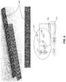
- FIG. 6shows an exemplary heating dissipating mechanism for the formation system, according to one embodiment of the present invention.
- FIG. 7shows the simplified floor plan of a building that houses a number of racks, according to one embodiment of the present invention.
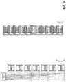
- FIG. 8shows the energy consumption of eight groups of cells, according to one embodiment of the present invention.
- FIG. 9shows the difference between the power supply chain in the present inventive cell formation system and a power supply chain in a conventional system, according to one embodiment of the present system.
- FIG. 10shows the space savings of the cell formation system, according to one embodiment of the present invention.
- Embodiments of the present inventioncan solve the technical problem of performing the post-assembly formation, conditioning, and testing process on rechargeable cells in a space- and energy-efficient, and scalable way, which can in turn reduce the cost of manufacturing rechargeable cells.
- a large number of cellscan be placed in the formation process together, typically in a conveyance tray.
- Conventional high-volume formation facilitiestypically consist of power supply and control modules coupled to battery contact fixtures, which hold the tray of cells and facilitate electrical connection to the individually controlled cells.
- Such systemsoften require a large number of cables (typically four or more wires per battery cell), take up a significant amount of space, and can be energy inefficient.
- the inefficiency from the power electronics and long cablescan result in heat rejection to the room, which often requires large ducted air cooling systems and could lead to variations in the cell temperature, thereby increasing the chance of error in the formation process.
- the existing formation facilitiesare typically designed without full consideration and optimization of the support systems.
- the existing designs and configurationsleave much room for improvement in high-volume manufacturing.
- many existing cell-formation systemsare not taking full advantage of the rapid advances in power conversion technology.
- the existing formation systemsoften exhibit the following characteristics:
- Embodiments of the present inventioncan solve the aforementioned problems by providing significant space saving, improved energy efficiency, more effective heat dissipation, and capability to accommodate more effective automation systems.
- a new design of the electrical circuit unit closely coupled with the contact boardcan accommodate a large number of cells undergoing the formation process in a densely packed manner.
- a hybrid cooling system that combines air and liquid coolingcan dissipate heat more effectively.
- an intelligent formation control systemthat stages the charge/discharge cycles among different cell groups can significantly reduce the power consumption and required power conversion capacity of the entire formation system.
- FIG. 1Ashows an exemplary configuration of an electrical circuit module and a contact module for cell formation, according to one embodiment of the present invention.
- contact module 102 and electrical circuit module 104are positioned adjacent to each other.
- a cell undergoing formation charge/discharge cyclingcan be placed in contact with the contact pins in one of the receptacles on contact module 102 .
- Circuit module 104can accommodate a number of electrical circuits, each corresponding to a receptacle on contact module 102 for accommodating a cell.
- Each cell-specific circuitcan be configured to supply well-controlled voltage to the cell housed in the receptacle, and collect measurements for the cell.
- this compact configuration of contact module 102 and circuit module 104which jointly form a cell interface block, can eliminate the need for a large amount of cabling, as is the case in a conventional formation system.
- a large amount of cablingcan be expensive, take up space, require long installation/repair time, can be a source of inefficiency, and can lead to less accuracy.
- contact module 102can contain multiple pogo pins in the receptacle, contact module 102 can also be referred to as a “pogo board.”
- contact module 102 and circuit module 104can be attached together with spacers 103 , so that the two modules can form one rigid entity.
- contact module 102can provide 32 receptacles to accommodate 32 cells at once. Other numbers of receptacles are also possible.
- the contact-module/circuit-module combinationcan be attached to a top platform 108 , and the cells undergoing formation can be held on a bottom platform 110 .
- Both top platform 108 and bottom platform 110can be housed in a frame 106 .
- top platform 108 and bottom platform 110can be actuated to move vertically in a “clamshell” manner. Specifically, actuator 122 can move bottom platform 110 upward, and actuator 124 can move top platform downward.
- Frame 106can therefore be referred to as a “clamshell structure.”
- top platform 108 and bottom platform 110can be actuated to move toward each other, so that the top of the cells can be in contact with the pins positioned inside each receptacle in the cell contact module (similar to contact module 102 ). It is also possible to fix the vertical position of bottom platform 110 and only move top platform 108 downward to contact the cells, or vice versa. Note that this one-sided actuation configuration has certain advantages. It can eliminate the complexity in the clamping fixture by using only one set of actuation mechanism and can reduce the overall space required for the clamping fixture by approximately one third.
- top-only cell connection configurationcan eliminate cables to the bottom of the cells, which also results in the aforementioned benefits.
- the contact and circuit modulesalso help eliminate the need for a separate power electronics module and long cable runs.
- Such dense packing of the cellscan lower the per-cell operational efficiency (operational expenditure, OPEX) and total CAPEX, which would not be attainable in a conventional formation system where the contact board and the power supply and control modules are separate from each other, which requires complex and space-consuming cabling to connect the two.
- a number of clamshell structurescan be housed in a larger rack, such as rack 112 .
- rack 112can accommodate six clamshell structures, bringing the total number of cells undergoing formation to 1536.
- Other numbers of clamshell structuresare also possible.
- bulky electrical componentssuch as system control and AC/DC power conversion module 114 , can be provisioned on a per-clamshell-structure basis and be placed in the vicinity of each clamshell structure.
- the AC/DC power conversion modulecan be provisioned in a centralized manner on a per-rack basis. More details are provided below in conjunction with FIG. 10 .
- FIG. 1Bshows an exemplary actuator-free clamping fixture, according to one embodiment of the present invention.
- a number of cells 140can be carried by conveyance tray 142 (actually number of cells not shown).
- Conveyance tray 142can have a number of receptacles for accommodating the cells and be used to transport the cells to and away from the rack.
- Electrical connection tray 148can contain built-in circuitry and spring-loaded connectors for connecting to the top of cells 140 .
- a robotic systemwhich can be part of a crane that transports conveyance tray 142 , can lower electrical connection tray 148 and mate cells 140 to the corresponding formation circuitry. Clamps 144 can be used to secure the mating position and ensure reliable contact between electrical connection tray 148 and cells 140 .
- electrical connection rails 146can be positioned on electrical connection tray 148 . These rails can be used to establish an electrical connection between electrical connection tray 148 and the connectors on the rack, which provide the power and other circuitry connection for the formation process. Note that rails 146 can also be used for guiding the robotic system for sliding the entire clamping fixture into a slot on a rack, optionally with blind-mate busbars. Furthermore, as described in conjunction with FIG.
- the clamping fixturecan also be mated to a thermal interface such as a blind coolant connector or plate with a low thermal resistance. Note that the actuator-free design of the clamping fixture shown in FIG. 1B can achieve even greater spatial density by eliminating actuators on every unit.
- FIG. 2shows a block diagram for an exemplary clamshell structure, according to one embodiment of the present invention.
- clamshell structure 202includes a cell interface block 204 , which is similar to the combined modules 102 and 103 in FIG. 1 .
- Cell interface block 204can have a number of receptacles, each configured to establish secure electrical contacts with a cell.
- each receptaclecan have a center probe and one or more outer probes.
- the center probecan be a Kelvin probe that contains more than one contact, which can form a Kelvin bridge with the outer probes for precise measurement of the cell.
- Cell interface block 204can be actuated by actuator 208 to move downward and be in contact with a number of cells 214 .
- the platform that supports cells 214can also be actuated to move upward.
- AC/DC power supply unit 210can convert high-voltage AC power to a low-voltage DC power, which can subsequently be controlled and distributed to the cells based on a predetermined cell formation, conditioning, and measurement process.
- a liquid coolant circulation pathcan be provided to clamshell structure 202 .
- liquid-cooled heat sinkscan be coupled to cell interface block 204 and/or the platform supporting cells 214 .
- an inlet pipecan supply coolant at approximately 36° C. to clamshell structure 202
- an outlet pipecan remove the outgoing coolant.
- Running the coolant at this temperatureallows the recovered heat to be used for other processes such as building heating, which further mitigates the overall costs of the formation process.
- a configuration that combines the use of heat pipe and cooling platecan be applied in conjunction with the cell interface modules.
- a second cooling systemcan be used to control the temperature of the AC/DC power unit.
- the manifolded componentscan function both as a structural support as well as a cooling plate or a heat sink for immersion cooling.
- immersion coolingin one embodiment, the AC/DC power unit can slide, using for example busbar-blind connections, into a dielectric coolant fluid, which can be pumped to a centralized heat exchanger.
- FIG. 3shows a block diagram of an exemplary power-supply and control configuration for a clamshell structure, according to one embodiment of the present invention.
- eight cell interface blockssuch as cell interface block 304 capable of accommodating 32 cells
- Each cell interface blockis coupled to a corresponding voltage division stage, which can control the DC power supplied to the corresponding cell interface block.
- the eight combinations of voltage division stage and cell interface blockcan be connected in series to divide a DC voltage supplied to the entire train of eight blocks.
- This in-series connectionhas a significant advantage over existing designs in that the majority of the power does not need to be processed in a DC-DC voltage conversion stage. As a result, this configuration can reduce inefficiency because less current is processed and converted, and can therefore help reduce the amount of total required power conversion capacity.
- conventional formation systemstypically have cell interface blocks connected in parallel, which requires additional DC voltage conversion.
- approximately 50V DCis provided by power supply unit 308 to the eight cell interface blocks connected in series.
- a pre-charge control unit 306can be coupled to power supply unit 308 and regulate the output DC voltage during a pre-charge stage when the cells undergo an off-gassing process to be prepared for the subsequent SEI layer formation.
- Main controller unit 310can be in communication with each cell interface block and control the timing and charging voltage supplied to the cells in each cell interface block.
- Main controller unit 310can also communicate with cooling system 312 , which can include a liquid cooling mechanism, and control the environment temperature.
- FIG. 4shows an exemplary DC-DC conversion and cell measurement circuit, according to one embodiment of the present invention.
- circuit module 402which is part of a cell interface block, has 32 sets of circuit for DC-DC conversion and cell measurement.
- a respective circuitcan include a Kelvin bridge circuit 412 for a cell 404 .
- a Kelvin bridge circuittypically includes a first pair of contacts, referred to as “force contacts,” to supply power (typically a current) to a device; and a second pair of contacts, referred to as “sensing contacts,” for taking measurement over the device.
- the power supply portion of Kelvin bridge 412includes a step-down DC-DC conversion circuit 414 , which includes a pair of gates 411 and 410 , inductor 406 , and capacitor 408 .
- Gates 411 and 410work jointly as a switch and rectifier, while inductor 406 and capacitor 408 function as an energy storage element. By controlling the switch duty cycle, one can control the voltage applied to cell 404 .
- FIGS. 5A-5Eshow various configurations of contacts in a cell receptacle, according to embodiments of the present invention.
- each receptaclecan have a center Kelvin probe 502 , which can connect to the cathode/positive contact of the cell, and an outer Kelvin probe 504 , which can connect to the anode/negative contact of the cell.
- Each Kelvin probeprovides two separate contact points, thereby facilitating a Kelvin bridge connection with the cell.
- the edge of each receptaclesuch as edge 506 , can be shaped with a ramp and function as a converging cup to help the cell be aligned with the receptacle.
- two center single probes 508can be positioned near the center of the receptacle to provide two separate contact points to the cell's cathode/positive contact as part of the Kelvin bridge connection.
- Two out single probes 510can be positioned near the outer edge of the receptacle to provide two separate contact points to the cell's anode/negative contact.
- the receptacle's outer edgecan be shaped with a ramp as a converging cup to help with cell alignment.
- FIG. 5Cshows another configuration, where each receptacle includes a center Kelvin probe 512 providing two separate contacts, and two outer spring tabs 514 and 516 .
- Spring tabs 514 and 516can be shaped to provide a guiding ramp to help with cell alignment.
- the edge of the receptaclecan be shaped as a converging cup for cell alignment, and the spring tabs can be positioned inside the converging cup.
- a center Kelvin probe 518provides two separate contact points to the cell's cathode/positive contact point.
- Two individual outer probes 520 and 522each being a single point of contact provide connection to the cell's anode/negative contact point.
- the outer probescan have angled tips, which can serve as guiding ramps to help with cell alignment.
- a number(such as 3 or 5) of small circular tipped probes 524 can be placed near the receptacle shoulder to provide contact with the cell's anode/negative contact point. These probes can be tilted toward the center to guide the cell for accurate alignment.
- a center Kelvin probe 526can provide two separate contacts, and can optionally have serrations to cut through the passivation layer on the aluminum cathode/positive contact point of the cell.
- the left drawing of FIG. 5Eshows the perspective view, whereas the right drawing of FIG. 5E shows the top view of the receptacle.
- each cell interface blockcan be coupled to a heat dissipating mechanism, which allows the formation system to operate under a controlled temperature.
- FIG. 6shows an exemplary heating dissipating mechanism for the formation system, according to one embodiment of the present invention.
- each of the eight cell interface blocks in a clamshell structurecan be coupled to a heat dissipating mechanism 606 .
- Heat dissipating mechanism 606can include a cold plate 602 and a heat pipe 604 .
- the bottom drawing of FIG. 6shows the conceptual configuration of the heat dissipating mechanism, and the top drawing of FIG. 6 shows the physical configuration of the heat dissipating mechanism having eight heat pipes coupled to a cooling plate.
- Heat pipescan be closed systems that typically include a sealed hollow tube with one end thermally coupled to a colder region away from the heat source.
- one of the heat pipesmay be thermally coupled to a cold plate that can removes heat from the heat pipe.
- the inside walls of the heat pipemay be lined with a capillary structure.
- the liquid in the capillary structurecan absorb heat though a phase change, which causes the liquid to evaporate and become a gas.
- the gascan migrate to the colder end of the heat pipe where it then condenses and becomes liquid again. As the vapor condenses, heat is removed from the system.
- the capillary structuremay then migrate the liquid back through the length of the heat pipe.
- Heat pipe 604can be attached to the circuit module board of the corresponding cell interface block and transfer heat away from the circuits. Heat pipe 604 is attached to cold plate 602 , which is liquid-cooled. The cold plates of the eight heat dissipating devices, each coupled to one of the eight cell interface blocks, can be attached to a common liquid coolant pathway. This configuration allows for use of liquid cooling without requiring a large number of liquid-tight connections.
- one or more cooling tubesmay be used instead of using heat pipe 604 . Cooling tubes can be open systems, which could introduce a potential failure point for the system over a closed heat-pipe system. In addition, cooling plates and tubes typically have more coolant interface points, which can increase the probability of leaks compared with a heat pipe. Heat pipes also make the system more modular for quick repair. For example, instead of disconnecting a fluid line connection, one can perform a face plate compression operation from a screw or spring-loaded clamp to replace a heat pipe.
- the cell-formation system design described abovecan be installed in a room with high space efficiency, due to the compact design of the clamshell structure and the rack shelf to house the clamshell structures.
- a number of rack shelves 702as the one shown in FIG. 1A , can be placed in close proximity with one another. In one embodiment, these shelves can be placed on tracks and be moved as needed like book shelves in a library.
- an automated crane or robotic system(such as cranes 704 ) can be used to maneuver trays of cells without human intervention (e.g., loading and unloading cells into the clamshell structures).
- FIG. 7a number of rack shelves 702 , as the one shown in FIG. 1A , can be placed in close proximity with one another. In one embodiment, these shelves can be placed on tracks and be moved as needed like book shelves in a library.
- an automated crane or robotic system(such as cranes 704 ) can be used to maneuver trays of cells without human intervention (e.g., loading and unloading cells into the clamshell structures).
- cranes 704can assemble these fixtures and slide them into racks 702 , which can further improve spatial density.
- valuable floor resourcesmay be saved by reducing the space between the shelves, such that only sufficient space for the crane is needed.
- the space reserved for air ductscan be freed. As a result, one can save the space reserved for traditional additional access ways or larger spacing between shelves for humans.
- the cellsare subject to a number of charge/discharge cycles, so that their capacity can be measured. These charge/discharge cycles can often consume a large amount of energy and generate undesirable heat.
- the charge/discharge cycles of different groups of cellscan be offset in the time domain, such that the discharge cycle of one group of cells can be used to power the charge cycle of a different group of cells.
- Each groupcontains 32 cells, which are connected to a corresponding cell interface block.
- Main controller unit 310can control the timing of each cell group's charge and discharge cycles, so that the discharge cycle of one group can be used to the charge of another group.
- a centralized room-level controllercan provide general instructions on when to start a charge/discharge cycle.
- FIG. 8shows the energy consumption of eight groups of cells, according to one embodiment of the present invention.
- the starting time of the charge/discharge cycles for each group of cellsis offset by a predetermined amount.
- the power consumptionis negative, it indicates that the group of cells are discharging and supplying power to other cells.
- the total power consumption of the eight groupscan be significantly reduced.
- This configurationcan also reduce the amount of required infrastructure for provisioning power. For example, instead of having cables that can carry 6 KW of power for each unit and the corresponding AC/DC and DC/DC conversion capacity, only 6 KW in total power can be sufficient.
- the controls for the cell groupscan also be centralized in the corresponding AC/DC module.
- FIG. 9shows the difference between the power supply chain in the present inventive cell formation system and a power supply chain in a conventional system, according to one embodiment of the present system.
- the top portion of FIG. 9shows a conventional power supply chain, which includes a substation and a transformer to bring a high-voltage AC power line down to a 208-V AC power supply. Subsequently, an AC/DC conversion unit converts the AC power to DC power. Two DC/DC voltage conversion units are then used to bring the DC voltage to 2.5-4.2 V to the cells.
- embodiments of the present inventionuses an AC/DC conversion unit to directly convert a 277 V AC power (after the substation and AC transformer) to a 50 V DC power.
- This 50 V DC poweris then shared among the clamshell structures housed in a rack (see FIG. 1 and FIG. 3 ). Within each clamshell structure, this 50 V DC power is further divided by the voltage division stage for each cell interface block to 2.5-4.2 V for the cells.
- FIG. 10shows the space savings of the cell formation system, according to one embodiment of the present invention.
- a conventional cell formation systemwhich requires a separate power supply unit for each group of cells.
- the present inventive systemas shown on the right, only needs one power supply unit for a number of clamshell structures, each of which can accommodate 256 cells. Therefore, the present inventive cell formation system can provide significant space savings.
- the height of each clamshell structuree.g., about 150 mm
- embodiments of the present inventionemploy a thermal strategy to reduce the heat that needs to be transferred by improving the formation system's efficiency and the use of cooling tunnels (described below).
- the use of liquid cooling or immersion coolingallows heat to be captured at higher temperatures, which makes it possible to use the captured energy in other parts of the building.
- the temperature experienced by each cellmay vary from cell to cell and from room to room.
- the cellscan be heated or cooled to a predetermined temperature, in a cooling tunnel, prior to entering the main area of the room where formation takes place.
- the cooling tunnelcan be a continuous process in which the cells are kept on a conveyor. Heat transfer can occur with high-velocity air, radiation-based cooling plates, thermal conduction through a carrier tray, direct resistive heating, or a combination of these approaches.
- the cooling tunnelcan apply a temperature profile. For example, initially, a more extreme temperature can be applied and then a cooling or heating process can be carried out to achieve a target cell temperature.
- a counter-flow approachcan be implemented that allows the cells entering the room to exchange heat with the cells leaving the room. That is, a cooling tunnel can be implemented to exchange heat between the cells entering the room and the cells leaving the room.
Landscapes
- Chemical & Material Sciences (AREA)
- Chemical Kinetics & Catalysis (AREA)
- Electrochemistry (AREA)
- General Chemical & Material Sciences (AREA)
- Engineering & Computer Science (AREA)
- Manufacturing & Machinery (AREA)
- Physics & Mathematics (AREA)
- General Physics & Mathematics (AREA)
- Materials Engineering (AREA)
- Secondary Cells (AREA)
Abstract
Description
- (1) Large physical footprint;
- (2) Low-efficiency and costly power electronics;
- (3) Overly complex clamping fixture;
- (4) Large amount of cabling that wastes energy, is costly, and reduces measurement accuracy;
- (5) Uses air cooling to transfer heat generated by inefficient power usage, which in turn consumes power to remove heat, takes up space, and is difficult to control without significant thermal gradients, which results in cell-to-cell variation.
- (1) Reduce capital expenditure (CAPEX) of the equipment and supporting facility infrastructure;
- (2) Improve energy efficiency;
- (3) Reduce thermal gradients in the room to reduce cell-to-cell temperature-based performance variation;
- (4) Increase volumetric density of the testers, which results in a number of cost savings in building and support systems;
- (5) Capture the waste heat at an elevated temperature, which allows the dissipated thermal energy to be used for different, useful purposes;
- (6) Facilitate hot-swappable components, thereby improving equipment utilization; and
- (7) Reduce fire risk.
Claims (16)
Priority Applications (1)
| Application Number | Priority Date | Filing Date | Title |
|---|---|---|---|
| US15/946,635US11043823B2 (en) | 2017-04-06 | 2018-04-05 | System and method for facilitating conditioning and testing of rechargeable battery cells |
Applications Claiming Priority (2)
| Application Number | Priority Date | Filing Date | Title |
|---|---|---|---|
| US201762482622P | 2017-04-06 | 2017-04-06 | |
| US15/946,635US11043823B2 (en) | 2017-04-06 | 2018-04-05 | System and method for facilitating conditioning and testing of rechargeable battery cells |
Publications (2)
| Publication Number | Publication Date |
|---|---|
| US20180294657A1 US20180294657A1 (en) | 2018-10-11 |
| US11043823B2true US11043823B2 (en) | 2021-06-22 |
Family
ID=63710007
Family Applications (1)
| Application Number | Title | Priority Date | Filing Date |
|---|---|---|---|
| US15/946,635Active2039-05-30US11043823B2 (en) | 2017-04-06 | 2018-04-05 | System and method for facilitating conditioning and testing of rechargeable battery cells |
Country Status (1)
| Country | Link |
|---|---|
| US (1) | US11043823B2 (en) |
Cited By (1)
| Publication number | Priority date | Publication date | Assignee | Title |
|---|---|---|---|---|
| US11616258B2 (en) | 2021-06-30 | 2023-03-28 | Enovix Corporation | Distributed cell formation systems for lithium containing secondary batteries |
Families Citing this family (11)
| Publication number | Priority date | Publication date | Assignee | Title |
|---|---|---|---|---|
| DE102019204034A1 (en)* | 2019-03-25 | 2020-10-01 | Siemens Aktiengesellschaft | High-voltage battery storage with high power density |
| CN110509786B (en)* | 2019-08-16 | 2021-12-03 | 浙江合众新能源汽车有限公司 | Electric automobile charging method, charging system and electric automobile |
| CN112255255B (en)* | 2020-10-14 | 2023-07-07 | 中国工程物理研究院电子工程研究所 | In-situ battery testing device and testing method based on neutron diffraction |
| KR102815177B1 (en)* | 2021-10-26 | 2025-05-30 | 주식회사 엘지에너지솔루션 | Cell tray |
| FR3136599A3 (en)* | 2022-06-10 | 2023-12-15 | Creatique Technologie | battery cell connection device |
| EP4290647A3 (en)* | 2022-06-10 | 2024-10-16 | Creatique Technologie | Device for connecting battery cells with a test bench |
| WO2024108196A1 (en)* | 2022-11-18 | 2024-05-23 | Our Next Energy, Inc. | Cell formation |
| WO2024259340A2 (en)* | 2023-06-16 | 2024-12-19 | Supernal, Llc | Text fixture for battery cells |
| EP4513698A1 (en)* | 2023-08-22 | 2025-02-26 | Siemens Aktiengesellschaft | Forming rechargeable battery cells with a power source |
| WO2025120509A1 (en)* | 2023-12-06 | 2025-06-12 | System Ceramics S.P.A. | Method for forming battery cells |
| WO2025120528A1 (en)* | 2023-12-06 | 2025-06-12 | System Ceramics S.P.A. | Warehouse for the formation of electrochemical cells |
Citations (141)
| Publication number | Priority date | Publication date | Assignee | Title |
|---|---|---|---|---|
| US4253044A (en)* | 1978-01-17 | 1981-02-24 | U.S. Philips Corporation | Gas discharge display panel, display apparatus comprising the panel and method of operating the display apparatus |
| US4322597A (en)* | 1980-06-30 | 1982-03-30 | General Electric Company | Method and apparatus for interconnecting electrochemical cells for a battery |
| US4330834A (en)* | 1979-05-02 | 1982-05-18 | International Business Machines Corp. | Graphics display apparatus |
| USRE30985E (en)* | 1978-01-01 | 1982-06-29 | Serum-free cell culture media | |
| US4352948A (en)* | 1979-09-07 | 1982-10-05 | Massachusetts Institute Of Technology | High-intensity solid-state solar-cell device |
| US4359075A (en)* | 1980-05-12 | 1982-11-16 | General Battery Corporation | Multiple position and work station for battery fabrication |
| US4368423A (en)* | 1981-01-13 | 1983-01-11 | Liburdy Robert P | Apparatus for determining cell membrane dielectric breakdown |
| US4407945A (en)* | 1981-04-29 | 1983-10-04 | Immunex Corporation | Constitutive production of interleukin 2 by a T cell hybridoma |
| US4411990A (en)* | 1979-06-13 | 1983-10-25 | University Patents, Inc. | Primary bioassay of human tumor stem cells |
| US4448879A (en)* | 1981-03-26 | 1984-05-15 | Hooper Trading Company | High yield process for in vitro production of serum-free and mitogen-free interleukin-2 |
| US4451587A (en)* | 1981-10-22 | 1984-05-29 | Takeda Chemical Industries, Ltd. | Polyurethane foam and its production |
| US4458531A (en)* | 1980-10-10 | 1984-07-10 | Wolfgang Mehlhardt | Method of and apparatus for examining biological effects in cell-lots |
| US4465897A (en)* | 1982-05-10 | 1984-08-14 | H. H. Robertson Company | Three-service wire distributing unit and outlet means therefor |
| US4467274A (en)* | 1981-05-15 | 1984-08-21 | Harco Corporation | Electrical surveys of underwater or underground structures with electrode-to-electrolyte potential correction |
| US4472506A (en)* | 1981-01-13 | 1984-09-18 | Liburdy Robert P | Method for determining cell membrane dielectric breakdown |
| US4473642A (en)* | 1981-04-29 | 1984-09-25 | Immunex Corporation | Constitutive production of interleukin 2 by a T cell hybridoma |
| US4486517A (en)* | 1982-10-18 | 1984-12-04 | Firma Emil Bender | Wet-cell storage battery |
| US4493909A (en)* | 1981-06-25 | 1985-01-15 | Bayer Aktiengesellschaft | Poly-N,N-hydroxyalkylamides of polybasic carboxylic acids and a process for the production thereof |
| US4501815A (en)* | 1979-10-29 | 1985-02-26 | Albert Einstein College Of Medicine Of Yeshiva University | Article for culturing differentiated cells |
| US4514499A (en)* | 1983-02-04 | 1985-04-30 | Corning Glass Works | Cell culture using a monolithic support |
| US4581187A (en)* | 1983-02-28 | 1986-04-08 | Sullivan James B | Method of manufacturing a molded composite elastomeric foam sheet innersole |
| US4590181A (en)* | 1982-12-20 | 1986-05-20 | Board Of Regents Of The University Of Nebraska | Synthetic immunoregulators and methods of use and preparation |
| US4627178A (en)* | 1983-02-28 | 1986-12-09 | Sullivan James B | Molded shoe innersole |
| US4816249A (en)* | 1981-11-17 | 1989-03-28 | The Board Of Trustees Of The Leland Stanford Junior University | Monoclonal anti-idiotype antibodies |
| US4816747A (en)* | 1981-05-15 | 1989-03-28 | Harco Technologies Corporation | Method and apparatus for electrical surveys of subsurface structures utilizing cell-to-cell techniques with correction to direct potential measurements |
| US4886604A (en)* | 1984-12-21 | 1989-12-12 | Uwe Sleytr | Structure with membranes having continuous pores |
| US4910886A (en)* | 1983-02-28 | 1990-03-27 | Sullivan James B | Shock-absorbing innersole |
| US4921801A (en)* | 1984-09-27 | 1990-05-01 | Eli Lilly And Company | Novel recombinant DNA cosmid shuttle vectors |
| US4962347A (en)* | 1988-02-25 | 1990-10-09 | Strategic Energy, Ltd. | Flashlight with battery tester |
| US4998284A (en)* | 1987-11-17 | 1991-03-05 | Cell Analysis Systems, Inc. | Dual color camera microscope and methodology for cell staining and analysis |
| US5023189A (en)* | 1990-05-04 | 1991-06-11 | Microwave Modules & Devices, Inc. | Method of thermal balancing RF power transistor array |
| US5180809A (en)* | 1988-05-20 | 1993-01-19 | La Jolla Cancer Research Foundation | Adhesion receptor for laminin and its use |
| US5213979A (en)* | 1987-12-30 | 1993-05-25 | W. R. Grace & Co.-Conn. | In vitro culture of bovine embryos |
| US5217170A (en)* | 1992-02-11 | 1993-06-08 | Gmd Engineered Systems, Inc. | Method for both cooling and pneumatically scrubbing a calcined, particulate material |
| US5217715A (en)* | 1988-08-01 | 1993-06-08 | The United States Of America As Represented By The Department Of Health And Human Services | Carbohydrate receptor for bacteria and method for use thereof |
| US5240606A (en)* | 1990-07-09 | 1993-08-31 | Cytyc Corporation | Apparatus for preparing cells for examination |
| US5240854A (en)* | 1989-06-05 | 1993-08-31 | Berry Eric S | Continuous high-density cell culture system |
| US5252409A (en)* | 1991-03-01 | 1993-10-12 | Osaka Gas Co., Ltd. | Fuel cell |
| US5272158A (en)* | 1991-10-29 | 1993-12-21 | Merck & Co., Inc. | Fibrinogen receptor antagonists |
| US5281585A (en)* | 1991-05-07 | 1994-01-25 | Merck & Co., Inc. | Fibrinogen receptor antagonists for inhibiting aggregation of blood platelets |
| US5283058A (en)* | 1990-08-30 | 1994-02-01 | The General Hospital Corporation | Methods for inhibiting rejection of transplanted tissue |
| US5283194A (en)* | 1991-07-22 | 1994-02-01 | Schmukler Robert E | Apparatus and methods for electroporation and electrofusion |
| US5321034A (en)* | 1991-05-07 | 1994-06-14 | Merck & Co., Inc. | Fibrinogen receptor antagonists |
| US5326691A (en)* | 1991-11-21 | 1994-07-05 | John Hozier | Micro-libraries and methods of making and manipulating them methods for generating and analyzing micro-libraries |
| US5330509A (en)* | 1992-04-06 | 1994-07-19 | Angeion Corporation | Method and apparatus for far-field tachycardia termination |
| US5348878A (en)* | 1990-05-10 | 1994-09-20 | Dana-Farber Cancer Institute | Class I MHC-restricted T-T hybridomas, and a CD8-transfected BW5147, fusion partner therefor |
| US5354738A (en)* | 1992-09-04 | 1994-10-11 | G. D. Searle & Co. | Platelet aggregation inhibitors |
| US5408463A (en)* | 1992-12-28 | 1995-04-18 | At&T Corp. | Resynchronization of asynchronous transfer mode (ATM) switch fabric |
| US5410170A (en)* | 1993-04-14 | 1995-04-25 | Siliconix Incorporated | DMOS power transistors with reduced number of contacts using integrated body-source connections |
| US5412123A (en)* | 1993-02-08 | 1995-05-02 | Glycomed Incorporated | Anthraquinone and anthracene derivatives as inhibitors of the cell-adhesion molecules of the immune system |
| US5416099A (en)* | 1991-10-29 | 1995-05-16 | Merck & Co., Inc. | Fibrinogen receptor antagonists |
| US5417972A (en)* | 1993-08-02 | 1995-05-23 | The Board Of Trustees Of The Leland Stanford Junior University | Method of killing B-cells in a complement independent and an ADCC independent manner using antibodies which specifically bind CDIM |
| US5425049A (en)* | 1993-10-25 | 1995-06-13 | Ericsson Ge Mobile Communications Inc. | Staggered frequency hopping cellular radio system |
| US5428818A (en)* | 1991-11-10 | 1995-06-27 | Motorola Inc. | Method and apparatus for reducing interference in a radio communication link of a cellular communication system |
| US5453272A (en)* | 1992-10-02 | 1995-09-26 | Alberta Research Council | Lectin derived carbohydrate binding-peptide |
| US5476783A (en)* | 1992-03-23 | 1995-12-19 | Koch Engineering Company, Inc. | Bioreactor method of culturing and propagating cells with a woven motionless mixing element |
| US5480642A (en)* | 1982-12-20 | 1996-01-02 | The Board Of Regents Of The University Of Nebraska | Synthetic immunoreglators, and methods of use and preparation |
| US5481533A (en)* | 1994-05-12 | 1996-01-02 | Bell Communications Research, Inc. | Hybrid intra-cell TDMA/inter-cell CDMA for wireless networks |
| US5484892A (en)* | 1993-05-21 | 1996-01-16 | Dana-Farber Cancer Institute, Inc. | Monoclonal antibodies that block ligand binding to the CD22 receptor in mature B cells |
| US5489594A (en)* | 1993-08-24 | 1996-02-06 | G. D. Searle & Co. | Platelet aggregation inhibitors |
| US5507034A (en)* | 1993-09-01 | 1996-04-09 | Telefonaktiebolaget Lm Ericsson | Channel selection in a cellular communication system |
| US5523980A (en)* | 1993-12-28 | 1996-06-04 | Kabushiki Kaisha Toshiba | Semiconductor memory device |
| US5537434A (en)* | 1993-10-25 | 1996-07-16 | Telefonaktiebolaget Lm Ericsson | Frequency hopping control channel in a radio communication system |
| US5552303A (en)* | 1993-03-08 | 1996-09-03 | Immunex Corporation | DNA encoding epithelium-derived T-cell factor |
| US5559718A (en)* | 1994-04-28 | 1996-09-24 | Cadence Design Systems, Inc. | System and method for model-based verification of local design rules |
| US5558956A (en)* | 1995-08-30 | 1996-09-24 | Gujer; Rudolf | System for isolating batteries during testing |
| US5565321A (en)* | 1993-01-22 | 1996-10-15 | Immunex Corporation | Detection of mutations in a CD40 ligand gene |
| US5574138A (en)* | 1993-03-08 | 1996-11-12 | Immunex Corporation | Epithelium-derived T-cell factor |
| US5591829A (en)* | 1987-05-29 | 1997-01-07 | Matsushita; Shuzo | Antibodies modified with toxic substance |
| US5602305A (en)* | 1994-03-31 | 1997-02-11 | Yale University | Immunodeficient animal model for studying T cell-mediated immune |
| US5622933A (en)* | 1993-09-13 | 1997-04-22 | Armel S.A. | Multiple branch peptide constructions for use against HIV |
| US5629412A (en)* | 1994-07-11 | 1997-05-13 | Glinskii; Guennadi V. | Synthetic glycoamines that promote or inhibit cell adhesion |
| US5638294A (en)* | 1993-12-21 | 1997-06-10 | Mitsubishi Denki Kabushiki Kaisha | Device and method for calculating delay time |
| US5643759A (en)* | 1993-10-30 | 1997-07-01 | Biotest Pharma Gmbh | Method for preparing bispecific monoclonal antibodies |
| US5649292A (en)* | 1994-10-31 | 1997-07-15 | Airnet Communications Corporation | Obtaining improved frequency reuse in wireless communication systems |
| US5656441A (en)* | 1994-04-19 | 1997-08-12 | Trustees Of Boston University | Methods for determining cellular adhesion |
| US5663051A (en)* | 1994-08-31 | 1997-09-02 | Activated Cell Therapy, Inc. | Separation apparatus and method |
| US5671221A (en)* | 1995-06-14 | 1997-09-23 | Sharp Microelectronics Technology, Inc. | Receiving method and apparatus for use in a spread-spectrum communication system |
| US5694262A (en)* | 1994-01-31 | 1997-12-02 | Fujitsu Ltd. | Method and apparatus for transferring data and making on-the-fly correction of errors |
| US5723130A (en)* | 1993-05-25 | 1998-03-03 | Hancock; Gerald E. | Adjuvants for vaccines against respiratory syncytial virus |
| US5728580A (en)* | 1996-02-20 | 1998-03-17 | Cornell Research Foundation, Inc. | Methods and culture media for inducing single cell suspension in insect cell lines |
| US5736143A (en)* | 1992-10-02 | 1998-04-07 | Alberta Research Council | Anti-inflammatory, tolerogenic and immunoinhibiting properties of carbohydrate binding-peptides |
| US5745486A (en)* | 1995-10-26 | 1998-04-28 | Northern Telecom Limited | High capacity ATM switch |
| US5764641A (en)* | 1995-09-08 | 1998-06-09 | Cisco Systems, Inc. | Early and integrated tail packet discard system |
| US5764581A (en)* | 1997-03-04 | 1998-06-09 | Advanced Micro Devices Inc. | Dynamic ram with two-transistor cell |
| US5817750A (en)* | 1995-08-28 | 1998-10-06 | La Jolla Cancer Research Foundation | Structural mimics of RGD-binding sites |
| US5817516A (en)* | 1994-04-28 | 1998-10-06 | Boehringer Ingelheim Pharmaceuticals, Inc. | Methods for proliferating and differentiating B cells with high density membrane CD40 ligand |
| US5830702A (en)* | 1990-10-31 | 1998-11-03 | The Trustees Of The University Of Pennsylvania | Live, recombinant listeria monocytogenes and production of cytotoxic T-cell response |
| US5831142A (en)* | 1994-01-07 | 1998-11-03 | Dana Farber Cancer Institute, Inc. | Regulatory elements controlling tissue-specific gene expression |
| US5837084A (en)* | 1995-09-14 | 1998-11-17 | Comfortex Corporation | Method of making a single-cell honeycomb fabric structure |
| US5856363A (en)* | 1992-06-30 | 1999-01-05 | John B. Davidson | Methods of using ajoene |
| US5855619A (en)* | 1994-06-06 | 1999-01-05 | Case Western Reserve University | Biomatrix for soft tissue regeneration |
| US5863955A (en)* | 1992-06-30 | 1999-01-26 | John B. Davidson | Methods of using ajoene to inhibit an immune response |
| US5863954A (en)* | 1992-06-30 | 1999-01-26 | John B. Davidson | Contraceptive method using ajoene |
| US5864024A (en)* | 1994-07-11 | 1999-01-26 | Glinskii; Guennadi Victor | Synthetic glycoamines and methods for their use that affect cell adhesion, inhibit cancer cell metastasis, and induce apoptosis |
| US5871969A (en)* | 1996-02-12 | 1999-02-16 | Human Genome Sciences, Inc. | Nucleic acids encoding human neuronal attachment factor-1 |
| US5894565A (en)* | 1996-05-20 | 1999-04-13 | Atmel Corporation | Field programmable gate array with distributed RAM and increased cell utilization |
| US5894212A (en)* | 1997-09-19 | 1999-04-13 | Tarrytown Consulting, Inc. | Discharge monitoring and isolating system for batteries |
| US5901354A (en)* | 1996-04-03 | 1999-05-04 | Motorola, Inc. | Method and apparatus for performing soft-handoff in a wireless communication system |
| US5907171A (en)* | 1995-05-18 | 1999-05-25 | Texas Instruments Incorporated | Method of making floating-gate memory-cell array with digital logic transistors |
| US5914609A (en)* | 1996-11-08 | 1999-06-22 | Bitrode Corporation | Method and system for battery charging and testing with semi-automatic calibration |
| US5948821A (en)* | 1992-06-30 | 1999-09-07 | John B. Davidson | Methods of using ajoene |
| US5955275A (en)* | 1997-02-14 | 1999-09-21 | Arcaris, Inc. | Methods for identifying nucleic acid sequences encoding agents that affect cellular phenotypes |
| US5981602A (en)* | 1992-06-30 | 1999-11-09 | John B. Davidson | Methods of using Ajoene for inhibiting integrin-mediated cell-cell fusion |
| US5989807A (en)* | 1992-05-13 | 1999-11-23 | Geron Corporation & Board Of Regents | Detecting cancerous conditions by assaying for telomerase activity |
| US5998184A (en)* | 1997-10-08 | 1999-12-07 | Unisyn Technologies, Inc. | Basket-type bioreactor |
| US6004812A (en)* | 1994-12-01 | 1999-12-21 | Beth Israel Medical Center, Inc. | In-vitro T-lymphopoiesis system |
| US6004759A (en)* | 1990-02-20 | 1999-12-21 | Board Of Regents, The University Of Texas System | Methods and compositions for diagnosing autoimmune insulin dependant diabetes mellitus |
| US6013495A (en)* | 1994-10-21 | 2000-01-11 | The Scripps Research Institute | Methods of use for integrin B1C cell growth inhibitor |
| US6022540A (en)* | 1997-09-04 | 2000-02-08 | Osiris Therapeutics, Inc. | Ligands that modulate differentiation of mesenchymal stem cells |
| US6022697A (en)* | 1996-11-29 | 2000-02-08 | The Regents Of The University Of California | Methods for the diagnosis and treatment of insulin-dependent diabetes mellitus |
| US6038166A (en)* | 1998-04-01 | 2000-03-14 | Invox Technology | High resolution multi-bit-per-cell memory |
| US6047247A (en)* | 1996-12-11 | 2000-04-04 | Matsushita Electric Industrial Co., Ltd. | Method of estimating degradation with consideration of hot carrier effects |
| US6091954A (en)* | 1994-09-01 | 2000-07-18 | Telefonaktiebolaget Lm Ericsson | Channel assignment in enhanced fixed-plan mobile communications systems |
| US6094584A (en)* | 1998-03-26 | 2000-07-25 | Lucent Technologies, Inc. | Method for operating a wireless telecommunications system |
| US6108238A (en)* | 1997-09-11 | 2000-08-22 | Kabushiki Kaisha Toshiba | Programmable semiconductor memory device having program voltages and verify voltages |
| US6106832A (en)* | 1993-01-22 | 2000-08-22 | Immunex Corporation | Treatment of individuals exhibiting defective CD40L |
| US6110897A (en)* | 1996-10-10 | 2000-08-29 | Glycorex Ab | Antiinflammatory cell adhesion inhibitors |
| US6114129A (en)* | 1998-06-26 | 2000-09-05 | Biomira, Inc. | Methods of detecting T-cell activation and treating disorders associated with T-cell dysfunction |
| US6137787A (en)* | 1997-04-03 | 2000-10-24 | Chawla; Kapil K. | Method and apparatus for resource assignment in a wireless communication system |
| US6156878A (en)* | 1994-02-10 | 2000-12-05 | The Board Of Trustees Of The Leland Stanford Junior University | Ligand (ACT-4-L) to a receptor on the surface of activated CD4+ T-cells |
| US6198743B1 (en)* | 1995-08-18 | 2001-03-06 | Alcatel Networks Corporation | Traffic policing in broadband networks |
| US6206839B1 (en)* | 1999-01-15 | 2001-03-27 | Marcy L. Zwelling-Aamot | Cervical cancer self-screening methods and apparatus |
| US6210959B1 (en)* | 1998-09-25 | 2001-04-03 | GSF-Forschungszentrum für Umwelt und Gesundheit GmbH | Apparatus for the cultivation and concentration of non-adherent cells as well as for co-cultivation of two different cell species |
| US6221665B1 (en)* | 1998-06-10 | 2001-04-24 | University Of South Florida | Electrofusion chamber |
| US6232088B1 (en)* | 1995-02-08 | 2001-05-15 | Phairson Medical, Inc. | Treatment and prevention of immune rejection reactions |
| US6235526B1 (en)* | 1996-05-03 | 2001-05-22 | Aventis Pharma Deutschland Gmbh | Nucleic acid constructs containing genes encoding transport signals |
| US6245522B1 (en)* | 1999-03-26 | 2001-06-12 | The Regents Of The University Of California | Master molecular rheostat switch for cell signaling |
| US20070105214A1 (en)* | 2005-11-09 | 2007-05-10 | Irm, Llc | Automated cellular assaying systems and related components and methods |
| US7786699B2 (en)* | 2005-01-25 | 2010-08-31 | Victhom Human Bionics, Inc. | Power supply charger and method of charging |
| US7859220B2 (en)* | 2001-10-19 | 2010-12-28 | Rovcal, Inc. | Method and apparatus for charging electrochemical cells |
| US8013571B2 (en)* | 2008-09-19 | 2011-09-06 | Better Place GmbH | Battery exchange station |
| US8120315B2 (en)* | 2007-03-26 | 2012-02-21 | The Gillette Company | Battery charger with mechanism to automatically load and unload batteries |
| US8906541B2 (en)* | 2012-01-27 | 2014-12-09 | Tesla Motors, Inc. | Battery module with integrated thermal management system |
| US9209440B2 (en)* | 2011-09-08 | 2015-12-08 | Ford Global Technologies, Llc | High voltage access prevention |
| US9438047B2 (en)* | 2008-08-19 | 2016-09-06 | Endress + Hauser Process Solutions Ag | Method for monitoring the state of charge, or remaining capacity, of a disposable or rechargeable battery |
| US9553343B2 (en)* | 2013-07-30 | 2017-01-24 | Johnson Controls Technology Company | Printed circuit board interconnect for cells in a battery system |
| US9577227B2 (en)* | 2013-10-17 | 2017-02-21 | Tesla Motors, Inc. | Cell module assemblies |
| US20170222207A1 (en)* | 2016-02-03 | 2017-08-03 | Boston-Power, Inc. | Battery Cell Connector, Interconnect Board And Battery Block System |
| US9893385B1 (en)* | 2015-04-23 | 2018-02-13 | Ambri Inc. | Battery management systems for energy storage devices |
| US9911951B2 (en)* | 2014-09-30 | 2018-03-06 | Johnson Controls Technology Company | Battery module compressed cell assembly |
- 2018
- 2018-04-05USUS15/946,635patent/US11043823B2/enactiveActive
Patent Citations (164)
| Publication number | Priority date | Publication date | Assignee | Title |
|---|---|---|---|---|
| USRE30985E (en)* | 1978-01-01 | 1982-06-29 | Serum-free cell culture media | |
| US4253044A (en)* | 1978-01-17 | 1981-02-24 | U.S. Philips Corporation | Gas discharge display panel, display apparatus comprising the panel and method of operating the display apparatus |
| US4330834A (en)* | 1979-05-02 | 1982-05-18 | International Business Machines Corp. | Graphics display apparatus |
| US4411990A (en)* | 1979-06-13 | 1983-10-25 | University Patents, Inc. | Primary bioassay of human tumor stem cells |
| US4352948A (en)* | 1979-09-07 | 1982-10-05 | Massachusetts Institute Of Technology | High-intensity solid-state solar-cell device |
| US4501815A (en)* | 1979-10-29 | 1985-02-26 | Albert Einstein College Of Medicine Of Yeshiva University | Article for culturing differentiated cells |
| US4359075A (en)* | 1980-05-12 | 1982-11-16 | General Battery Corporation | Multiple position and work station for battery fabrication |
| US4322597A (en)* | 1980-06-30 | 1982-03-30 | General Electric Company | Method and apparatus for interconnecting electrochemical cells for a battery |
| US4458531A (en)* | 1980-10-10 | 1984-07-10 | Wolfgang Mehlhardt | Method of and apparatus for examining biological effects in cell-lots |
| US4472506A (en)* | 1981-01-13 | 1984-09-18 | Liburdy Robert P | Method for determining cell membrane dielectric breakdown |
| US4368423A (en)* | 1981-01-13 | 1983-01-11 | Liburdy Robert P | Apparatus for determining cell membrane dielectric breakdown |
| US4448879A (en)* | 1981-03-26 | 1984-05-15 | Hooper Trading Company | High yield process for in vitro production of serum-free and mitogen-free interleukin-2 |
| US4407945A (en)* | 1981-04-29 | 1983-10-04 | Immunex Corporation | Constitutive production of interleukin 2 by a T cell hybridoma |
| US4473642A (en)* | 1981-04-29 | 1984-09-25 | Immunex Corporation | Constitutive production of interleukin 2 by a T cell hybridoma |
| US4467274A (en)* | 1981-05-15 | 1984-08-21 | Harco Corporation | Electrical surveys of underwater or underground structures with electrode-to-electrolyte potential correction |
| US4816747A (en)* | 1981-05-15 | 1989-03-28 | Harco Technologies Corporation | Method and apparatus for electrical surveys of subsurface structures utilizing cell-to-cell techniques with correction to direct potential measurements |
| US4493909A (en)* | 1981-06-25 | 1985-01-15 | Bayer Aktiengesellschaft | Poly-N,N-hydroxyalkylamides of polybasic carboxylic acids and a process for the production thereof |
| US4451587A (en)* | 1981-10-22 | 1984-05-29 | Takeda Chemical Industries, Ltd. | Polyurethane foam and its production |
| US4816249A (en)* | 1981-11-17 | 1989-03-28 | The Board Of Trustees Of The Leland Stanford Junior University | Monoclonal anti-idiotype antibodies |
| US4465897A (en)* | 1982-05-10 | 1984-08-14 | H. H. Robertson Company | Three-service wire distributing unit and outlet means therefor |
| US4486517A (en)* | 1982-10-18 | 1984-12-04 | Firma Emil Bender | Wet-cell storage battery |
| US4590181A (en)* | 1982-12-20 | 1986-05-20 | Board Of Regents Of The University Of Nebraska | Synthetic immunoregulators and methods of use and preparation |
| US5480642A (en)* | 1982-12-20 | 1996-01-02 | The Board Of Regents Of The University Of Nebraska | Synthetic immunoreglators, and methods of use and preparation |
| US4514499A (en)* | 1983-02-04 | 1985-04-30 | Corning Glass Works | Cell culture using a monolithic support |
| US4910886A (en)* | 1983-02-28 | 1990-03-27 | Sullivan James B | Shock-absorbing innersole |
| US4627178A (en)* | 1983-02-28 | 1986-12-09 | Sullivan James B | Molded shoe innersole |
| US4910886B1 (en)* | 1983-02-28 | 1995-05-09 | Atlantic Thermoplastics Co Inc | Shock-absorbing innersole |
| US4581187A (en)* | 1983-02-28 | 1986-04-08 | Sullivan James B | Method of manufacturing a molded composite elastomeric foam sheet innersole |
| US4921801A (en)* | 1984-09-27 | 1990-05-01 | Eli Lilly And Company | Novel recombinant DNA cosmid shuttle vectors |
| US4886604A (en)* | 1984-12-21 | 1989-12-12 | Uwe Sleytr | Structure with membranes having continuous pores |
| US5591829A (en)* | 1987-05-29 | 1997-01-07 | Matsushita; Shuzo | Antibodies modified with toxic substance |
| US4998284A (en)* | 1987-11-17 | 1991-03-05 | Cell Analysis Systems, Inc. | Dual color camera microscope and methodology for cell staining and analysis |
| US5213979A (en)* | 1987-12-30 | 1993-05-25 | W. R. Grace & Co.-Conn. | In vitro culture of bovine embryos |
| US4962347A (en)* | 1988-02-25 | 1990-10-09 | Strategic Energy, Ltd. | Flashlight with battery tester |
| US5180809A (en)* | 1988-05-20 | 1993-01-19 | La Jolla Cancer Research Foundation | Adhesion receptor for laminin and its use |
| US5217715A (en)* | 1988-08-01 | 1993-06-08 | The United States Of America As Represented By The Department Of Health And Human Services | Carbohydrate receptor for bacteria and method for use thereof |
| US5386027A (en)* | 1988-08-01 | 1995-01-31 | The United States Of America As Represented By The Department Of Health & Human Services | Carbohydrate receptor for bacteria and method for use thereof |
| US5389521A (en)* | 1988-08-01 | 1995-02-14 | The United States Of America As Represented By The Department Of Health And Human Services | Carbohydrate receptor for bacteria and method for use thereof |
| US5240854A (en)* | 1989-06-05 | 1993-08-31 | Berry Eric S | Continuous high-density cell culture system |
| US6004759A (en)* | 1990-02-20 | 1999-12-21 | Board Of Regents, The University Of Texas System | Methods and compositions for diagnosing autoimmune insulin dependant diabetes mellitus |
| US5023189A (en)* | 1990-05-04 | 1991-06-11 | Microwave Modules & Devices, Inc. | Method of thermal balancing RF power transistor array |
| US5348878A (en)* | 1990-05-10 | 1994-09-20 | Dana-Farber Cancer Institute | Class I MHC-restricted T-T hybridomas, and a CD8-transfected BW5147, fusion partner therefor |
| US5240606A (en)* | 1990-07-09 | 1993-08-31 | Cytyc Corporation | Apparatus for preparing cells for examination |
| US5283058A (en)* | 1990-08-30 | 1994-02-01 | The General Hospital Corporation | Methods for inhibiting rejection of transplanted tissue |
| US5783216A (en)* | 1990-08-30 | 1998-07-21 | The General Hospital Corporation | Methods for inhibiting rejection of transplanted tissue |
| US5830702A (en)* | 1990-10-31 | 1998-11-03 | The Trustees Of The University Of Pennsylvania | Live, recombinant listeria monocytogenes and production of cytotoxic T-cell response |
| US5252409A (en)* | 1991-03-01 | 1993-10-12 | Osaka Gas Co., Ltd. | Fuel cell |
| US5281585A (en)* | 1991-05-07 | 1994-01-25 | Merck & Co., Inc. | Fibrinogen receptor antagonists for inhibiting aggregation of blood platelets |
| US5321034A (en)* | 1991-05-07 | 1994-06-14 | Merck & Co., Inc. | Fibrinogen receptor antagonists |
| US5283194A (en)* | 1991-07-22 | 1994-02-01 | Schmukler Robert E | Apparatus and methods for electroporation and electrofusion |
| US5416099A (en)* | 1991-10-29 | 1995-05-16 | Merck & Co., Inc. | Fibrinogen receptor antagonists |
| US5272158A (en)* | 1991-10-29 | 1993-12-21 | Merck & Co., Inc. | Fibrinogen receptor antagonists |
| US5678187A (en)* | 1991-11-10 | 1997-10-14 | Motorola, Inc. | Method and apparatus for reducing interference in a radio communication link of a cellular communication system |
| US5428818A (en)* | 1991-11-10 | 1995-06-27 | Motorola Inc. | Method and apparatus for reducing interference in a radio communication link of a cellular communication system |
| US5809401A (en)* | 1991-11-10 | 1998-09-15 | Motorola, Inc. | Method and apparatus for reducing interference in a radio communication link of a cellular communication system |
| US5563060A (en)* | 1991-11-21 | 1996-10-08 | Hozier; John | Micro-libraries for screening cell populations |
| US5326691A (en)* | 1991-11-21 | 1994-07-05 | John Hozier | Micro-libraries and methods of making and manipulating them methods for generating and analyzing micro-libraries |
| US5217170A (en)* | 1992-02-11 | 1993-06-08 | Gmd Engineered Systems, Inc. | Method for both cooling and pneumatically scrubbing a calcined, particulate material |
| US5476783A (en)* | 1992-03-23 | 1995-12-19 | Koch Engineering Company, Inc. | Bioreactor method of culturing and propagating cells with a woven motionless mixing element |
| US5565361A (en)* | 1992-03-23 | 1996-10-15 | Koch Engineering Company, Inc. | Bioreactor for culturing and propagating cells with a woven motionless mixing element |
| US5330509A (en)* | 1992-04-06 | 1994-07-19 | Angeion Corporation | Method and apparatus for far-field tachycardia termination |
| US5989807A (en)* | 1992-05-13 | 1999-11-23 | Geron Corporation & Board Of Regents | Detecting cancerous conditions by assaying for telomerase activity |
| US5948821A (en)* | 1992-06-30 | 1999-09-07 | John B. Davidson | Methods of using ajoene |
| US5863954A (en)* | 1992-06-30 | 1999-01-26 | John B. Davidson | Contraceptive method using ajoene |
| US5863955A (en)* | 1992-06-30 | 1999-01-26 | John B. Davidson | Methods of using ajoene to inhibit an immune response |
| US5856363A (en)* | 1992-06-30 | 1999-01-05 | John B. Davidson | Methods of using ajoene |
| US5981602A (en)* | 1992-06-30 | 1999-11-09 | John B. Davidson | Methods of using Ajoene for inhibiting integrin-mediated cell-cell fusion |
| US5354738A (en)* | 1992-09-04 | 1994-10-11 | G. D. Searle & Co. | Platelet aggregation inhibitors |
| US6245883B1 (en)* | 1992-10-02 | 2001-06-12 | Alberta Research Council | Anti-flammatory carbohydrate binding-peptides |
| US5453272A (en)* | 1992-10-02 | 1995-09-26 | Alberta Research Council | Lectin derived carbohydrate binding-peptide |
| US5833990A (en)* | 1992-10-02 | 1998-11-10 | Alberta Research Council | Anti-inflammatory, tolerogenic and immunoinhibiting properties of carbohydrate binding peptides |
| US5736143A (en)* | 1992-10-02 | 1998-04-07 | Alberta Research Council | Anti-inflammatory, tolerogenic and immunoinhibiting properties of carbohydrate binding-peptides |
| US5747040A (en)* | 1992-10-02 | 1998-05-05 | Alberta Research Council | Anti-inflammatory, tolerogenic and immunoinhibiting properties of carbohydrate binding-peptides |
| US5408463A (en)* | 1992-12-28 | 1995-04-18 | At&T Corp. | Resynchronization of asynchronous transfer mode (ATM) switch fabric |
| US5565321A (en)* | 1993-01-22 | 1996-10-15 | Immunex Corporation | Detection of mutations in a CD40 ligand gene |
| US6106832A (en)* | 1993-01-22 | 2000-08-22 | Immunex Corporation | Treatment of individuals exhibiting defective CD40L |
| US5412123A (en)* | 1993-02-08 | 1995-05-02 | Glycomed Incorporated | Anthraquinone and anthracene derivatives as inhibitors of the cell-adhesion molecules of the immune system |
| US5552303A (en)* | 1993-03-08 | 1996-09-03 | Immunex Corporation | DNA encoding epithelium-derived T-cell factor |
| US5892001A (en)* | 1993-03-08 | 1999-04-06 | Immunex Corporation | Epithelium-derived T-cell factor antibodies |
| US5985262A (en)* | 1993-03-08 | 1999-11-16 | Immunex Corporation | Method of treatment with epithelium derived T-cell factor |
| US6184359B1 (en)* | 1993-03-08 | 2001-02-06 | Immunex Corporation | Antibodies to epithelium-derived T-cell factor |
| US5574138A (en)* | 1993-03-08 | 1996-11-12 | Immunex Corporation | Epithelium-derived T-cell factor |
| US5707616A (en)* | 1993-03-08 | 1998-01-13 | Immunex Corporation | Method for treating or preventing gastrointestinal disease with epithelium-derived T-cell factor |
| US5866931A (en)* | 1993-04-14 | 1999-02-02 | Siliconix Incorporated | DMOS power transistor with reduced number of contacts using integrated body-source connections |
| US5410170A (en)* | 1993-04-14 | 1995-04-25 | Siliconix Incorporated | DMOS power transistors with reduced number of contacts using integrated body-source connections |
| US5484892A (en)* | 1993-05-21 | 1996-01-16 | Dana-Farber Cancer Institute, Inc. | Monoclonal antibodies that block ligand binding to the CD22 receptor in mature B cells |
| US5723130A (en)* | 1993-05-25 | 1998-03-03 | Hancock; Gerald E. | Adjuvants for vaccines against respiratory syncytial virus |
| US5417972A (en)* | 1993-08-02 | 1995-05-23 | The Board Of Trustees Of The Leland Stanford Junior University | Method of killing B-cells in a complement independent and an ADCC independent manner using antibodies which specifically bind CDIM |
| US5593676A (en)* | 1993-08-02 | 1997-01-14 | The Leland Stanford Junior University | Method of killing B cells using antibodies which bind CDIM |
| US5489594A (en)* | 1993-08-24 | 1996-02-06 | G. D. Searle & Co. | Platelet aggregation inhibitors |
| US5507034A (en)* | 1993-09-01 | 1996-04-09 | Telefonaktiebolaget Lm Ericsson | Channel selection in a cellular communication system |
| US5622933A (en)* | 1993-09-13 | 1997-04-22 | Armel S.A. | Multiple branch peptide constructions for use against HIV |
| US5425049A (en)* | 1993-10-25 | 1995-06-13 | Ericsson Ge Mobile Communications Inc. | Staggered frequency hopping cellular radio system |
| US5537434A (en)* | 1993-10-25 | 1996-07-16 | Telefonaktiebolaget Lm Ericsson | Frequency hopping control channel in a radio communication system |
| US5643759A (en)* | 1993-10-30 | 1997-07-01 | Biotest Pharma Gmbh | Method for preparing bispecific monoclonal antibodies |
| US5638294A (en)* | 1993-12-21 | 1997-06-10 | Mitsubishi Denki Kabushiki Kaisha | Device and method for calculating delay time |
| US5523980A (en)* | 1993-12-28 | 1996-06-04 | Kabushiki Kaisha Toshiba | Semiconductor memory device |
| US5831142A (en)* | 1994-01-07 | 1998-11-03 | Dana Farber Cancer Institute, Inc. | Regulatory elements controlling tissue-specific gene expression |
| US5694262A (en)* | 1994-01-31 | 1997-12-02 | Fujitsu Ltd. | Method and apparatus for transferring data and making on-the-fly correction of errors |
| US6156878A (en)* | 1994-02-10 | 2000-12-05 | The Board Of Trustees Of The Leland Stanford Junior University | Ligand (ACT-4-L) to a receptor on the surface of activated CD4+ T-cells |
| US6242566B1 (en)* | 1994-02-10 | 2001-06-05 | Board Of Trustees Of The Leland Stanford Junior University | Ligand (ACT-4-L) to a receptor on the surface of activated CD4+ T-cells |
| US5602305A (en)* | 1994-03-31 | 1997-02-11 | Yale University | Immunodeficient animal model for studying T cell-mediated immune |
| US5656441A (en)* | 1994-04-19 | 1997-08-12 | Trustees Of Boston University | Methods for determining cellular adhesion |
| US5559718A (en)* | 1994-04-28 | 1996-09-24 | Cadence Design Systems, Inc. | System and method for model-based verification of local design rules |
| US5817516A (en)* | 1994-04-28 | 1998-10-06 | Boehringer Ingelheim Pharmaceuticals, Inc. | Methods for proliferating and differentiating B cells with high density membrane CD40 ligand |
| US5481533A (en)* | 1994-05-12 | 1996-01-02 | Bell Communications Research, Inc. | Hybrid intra-cell TDMA/inter-cell CDMA for wireless networks |
| US5855619A (en)* | 1994-06-06 | 1999-01-05 | Case Western Reserve University | Biomatrix for soft tissue regeneration |
| US5629412A (en)* | 1994-07-11 | 1997-05-13 | Glinskii; Guennadi V. | Synthetic glycoamines that promote or inhibit cell adhesion |
| US5864024A (en)* | 1994-07-11 | 1999-01-26 | Glinskii; Guennadi Victor | Synthetic glycoamines and methods for their use that affect cell adhesion, inhibit cancer cell metastasis, and induce apoptosis |
| US5663051A (en)* | 1994-08-31 | 1997-09-02 | Activated Cell Therapy, Inc. | Separation apparatus and method |
| US6091954A (en)* | 1994-09-01 | 2000-07-18 | Telefonaktiebolaget Lm Ericsson | Channel assignment in enhanced fixed-plan mobile communications systems |
| US6013495A (en)* | 1994-10-21 | 2000-01-11 | The Scripps Research Institute | Methods of use for integrin B1C cell growth inhibitor |
| US5649292A (en)* | 1994-10-31 | 1997-07-15 | Airnet Communications Corporation | Obtaining improved frequency reuse in wireless communication systems |
| US6004812A (en)* | 1994-12-01 | 1999-12-21 | Beth Israel Medical Center, Inc. | In-vitro T-lymphopoiesis system |
| US6232088B1 (en)* | 1995-02-08 | 2001-05-15 | Phairson Medical, Inc. | Treatment and prevention of immune rejection reactions |
| US5907171A (en)* | 1995-05-18 | 1999-05-25 | Texas Instruments Incorporated | Method of making floating-gate memory-cell array with digital logic transistors |
| US5671221A (en)* | 1995-06-14 | 1997-09-23 | Sharp Microelectronics Technology, Inc. | Receiving method and apparatus for use in a spread-spectrum communication system |
| US6198743B1 (en)* | 1995-08-18 | 2001-03-06 | Alcatel Networks Corporation | Traffic policing in broadband networks |
| US5955572A (en)* | 1995-08-28 | 1999-09-21 | La Jolla Cancer Research Foundation | Structural mimics of RGD-binding sites |
| US5817750A (en)* | 1995-08-28 | 1998-10-06 | La Jolla Cancer Research Foundation | Structural mimics of RGD-binding sites |
| US5558956A (en)* | 1995-08-30 | 1996-09-24 | Gujer; Rudolf | System for isolating batteries during testing |
| US5764641A (en)* | 1995-09-08 | 1998-06-09 | Cisco Systems, Inc. | Early and integrated tail packet discard system |
| US5837084A (en)* | 1995-09-14 | 1998-11-17 | Comfortex Corporation | Method of making a single-cell honeycomb fabric structure |
| US5745486A (en)* | 1995-10-26 | 1998-04-28 | Northern Telecom Limited | High capacity ATM switch |
| US5871969A (en)* | 1996-02-12 | 1999-02-16 | Human Genome Sciences, Inc. | Nucleic acids encoding human neuronal attachment factor-1 |
| US5728580A (en)* | 1996-02-20 | 1998-03-17 | Cornell Research Foundation, Inc. | Methods and culture media for inducing single cell suspension in insect cell lines |
| US5901354A (en)* | 1996-04-03 | 1999-05-04 | Motorola, Inc. | Method and apparatus for performing soft-handoff in a wireless communication system |
| US6235526B1 (en)* | 1996-05-03 | 2001-05-22 | Aventis Pharma Deutschland Gmbh | Nucleic acid constructs containing genes encoding transport signals |
| US6026227A (en)* | 1996-05-20 | 2000-02-15 | Atmel Corporation | FPGA logic cell internal structure including pair of look-up tables |
| US6167559A (en)* | 1996-05-20 | 2000-12-26 | Atmel Corporation | FPGA structure having main, column and sector clock lines |
| US6014509A (en)* | 1996-05-20 | 2000-01-11 | Atmel Corporation | Field programmable gate array having access to orthogonal and diagonal adjacent neighboring cells |
| US5894565A (en)* | 1996-05-20 | 1999-04-13 | Atmel Corporation | Field programmable gate array with distributed RAM and increased cell utilization |
| US6110897A (en)* | 1996-10-10 | 2000-08-29 | Glycorex Ab | Antiinflammatory cell adhesion inhibitors |
| US5914609A (en)* | 1996-11-08 | 1999-06-22 | Bitrode Corporation | Method and system for battery charging and testing with semi-automatic calibration |
| US6207159B1 (en)* | 1996-11-29 | 2001-03-27 | The Regents Of The University Of California | Methods for the diagnosis and treatment of insulin-dependent diabetes mellitus |
| US6022697A (en)* | 1996-11-29 | 2000-02-08 | The Regents Of The University Of California | Methods for the diagnosis and treatment of insulin-dependent diabetes mellitus |
| US6047247A (en)* | 1996-12-11 | 2000-04-04 | Matsushita Electric Industrial Co., Ltd. | Method of estimating degradation with consideration of hot carrier effects |
| US5955275A (en)* | 1997-02-14 | 1999-09-21 | Arcaris, Inc. | Methods for identifying nucleic acid sequences encoding agents that affect cellular phenotypes |
| US5764581A (en)* | 1997-03-04 | 1998-06-09 | Advanced Micro Devices Inc. | Dynamic ram with two-transistor cell |
| US6137787A (en)* | 1997-04-03 | 2000-10-24 | Chawla; Kapil K. | Method and apparatus for resource assignment in a wireless communication system |
| US6022540A (en)* | 1997-09-04 | 2000-02-08 | Osiris Therapeutics, Inc. | Ligands that modulate differentiation of mesenchymal stem cells |
| US6108238A (en)* | 1997-09-11 | 2000-08-22 | Kabushiki Kaisha Toshiba | Programmable semiconductor memory device having program voltages and verify voltages |
| US5894212A (en)* | 1997-09-19 | 1999-04-13 | Tarrytown Consulting, Inc. | Discharge monitoring and isolating system for batteries |
| US5998184A (en)* | 1997-10-08 | 1999-12-07 | Unisyn Technologies, Inc. | Basket-type bioreactor |
| US6094584A (en)* | 1998-03-26 | 2000-07-25 | Lucent Technologies, Inc. | Method for operating a wireless telecommunications system |
| US6038166A (en)* | 1998-04-01 | 2000-03-14 | Invox Technology | High resolution multi-bit-per-cell memory |
| US6221665B1 (en)* | 1998-06-10 | 2001-04-24 | University Of South Florida | Electrofusion chamber |
| US6114129A (en)* | 1998-06-26 | 2000-09-05 | Biomira, Inc. | Methods of detecting T-cell activation and treating disorders associated with T-cell dysfunction |
| US6210959B1 (en)* | 1998-09-25 | 2001-04-03 | GSF-Forschungszentrum für Umwelt und Gesundheit GmbH | Apparatus for the cultivation and concentration of non-adherent cells as well as for co-cultivation of two different cell species |
| US6206839B1 (en)* | 1999-01-15 | 2001-03-27 | Marcy L. Zwelling-Aamot | Cervical cancer self-screening methods and apparatus |
| US6245522B1 (en)* | 1999-03-26 | 2001-06-12 | The Regents Of The University Of California | Master molecular rheostat switch for cell signaling |
| US7859220B2 (en)* | 2001-10-19 | 2010-12-28 | Rovcal, Inc. | Method and apparatus for charging electrochemical cells |
| US7786699B2 (en)* | 2005-01-25 | 2010-08-31 | Victhom Human Bionics, Inc. | Power supply charger and method of charging |
| US20070105214A1 (en)* | 2005-11-09 | 2007-05-10 | Irm, Llc | Automated cellular assaying systems and related components and methods |
| US8120315B2 (en)* | 2007-03-26 | 2012-02-21 | The Gillette Company | Battery charger with mechanism to automatically load and unload batteries |
| US9438047B2 (en)* | 2008-08-19 | 2016-09-06 | Endress + Hauser Process Solutions Ag | Method for monitoring the state of charge, or remaining capacity, of a disposable or rechargeable battery |
| US8013571B2 (en)* | 2008-09-19 | 2011-09-06 | Better Place GmbH | Battery exchange station |
| US9209440B2 (en)* | 2011-09-08 | 2015-12-08 | Ford Global Technologies, Llc | High voltage access prevention |
| US8906541B2 (en)* | 2012-01-27 | 2014-12-09 | Tesla Motors, Inc. | Battery module with integrated thermal management system |
| US9553343B2 (en)* | 2013-07-30 | 2017-01-24 | Johnson Controls Technology Company | Printed circuit board interconnect for cells in a battery system |
| US9577227B2 (en)* | 2013-10-17 | 2017-02-21 | Tesla Motors, Inc. | Cell module assemblies |
| US9911951B2 (en)* | 2014-09-30 | 2018-03-06 | Johnson Controls Technology Company | Battery module compressed cell assembly |
| US9893385B1 (en)* | 2015-04-23 | 2018-02-13 | Ambri Inc. | Battery management systems for energy storage devices |
| US20170222207A1 (en)* | 2016-02-03 | 2017-08-03 | Boston-Power, Inc. | Battery Cell Connector, Interconnect Board And Battery Block System |
Cited By (1)
| Publication number | Priority date | Publication date | Assignee | Title |
|---|---|---|---|---|
| US11616258B2 (en) | 2021-06-30 | 2023-03-28 | Enovix Corporation | Distributed cell formation systems for lithium containing secondary batteries |
Also Published As
| Publication number | Publication date |
|---|---|
| US20180294657A1 (en) | 2018-10-11 |
Similar Documents
| Publication | Publication Date | Title |
|---|---|---|
| US11043823B2 (en) | System and method for facilitating conditioning and testing of rechargeable battery cells | |
| CN111029667B (en) | Battery heating systems, electric vehicles and in-vehicle systems | |
| US11094977B2 (en) | Battery thermal management system with passive battery pack cooling | |
| US11958372B2 (en) | Device for bi-directional power conversion and charging for use with electric vehicles | |
| Steinhorst et al. | Smart cells for embedded battery management | |
| CN113273016A (en) | Method and system for battery pack thermal management | |
| US20130288096A1 (en) | Modular battery | |
| US20110151298A1 (en) | Battery pack and vehicle including the battery pack | |
| US20200403283A1 (en) | Self-activating thermal management system for battery pack | |
| CN105655528B (en) | Battery module and driving method thereof | |
| CN110476296B (en) | Power supply system | |
| US11978913B2 (en) | Battery power management for a battery backup unit (BBU) shelf | |
| Huang et al. | A review of management architectures and balancing strategies in smart batteries | |
| CN107925138A (en) | Energy storage device with reduced temperature variability between cells | |
| JP7698644B2 (en) | Power supply devices and their components | |
| KR102448544B1 (en) | Modularized high-precision charger/discharger sub-rack assembly structure | |
| CN109728352A (en) | Chemical production line and method | |
| WO2020004929A1 (en) | Thermoelectric cooling method and device | |
| CN109274149B (en) | Electrical energy exchange device, battery device and battery maintenance system | |
| Bhattarai et al. | Review of equalization techniques applied to second-life EV battery packs and their efficiency | |
| CN109980956B (en) | Direct current power supply | |
| Abareshi et al. | Fast active balancing circuit for Li-ion battery modules using a DC-DC bipolar converter | |
| CN108140764B (en) | Energy storage device with improved thermal performance | |
| Valchev et al. | Improvement on LiFePO4 cell balancing algorithm | |
| Zabetian‐Hosseini et al. | A finite‐state machine‐based control design for thermal and state‐of‐charge balancing of lithium iron phosphate battery using flyback converters |
Legal Events
| Date | Code | Title | Description |
|---|---|---|---|
| FEPP | Fee payment procedure | Free format text:ENTITY STATUS SET TO UNDISCOUNTED (ORIGINAL EVENT CODE: BIG.); ENTITY STATUS OF PATENT OWNER: LARGE ENTITY | |
| AS | Assignment | Owner name:TESLA, INC., CALIFORNIA Free format text:ASSIGNMENT OF ASSIGNORS INTEREST;ASSIGNORS:MATTHEWS, KEVIN;CALDWELL, TURNER;SUKUP, MARTIN;SIGNING DATES FROM 20180405 TO 20180422;REEL/FRAME:045757/0318 | |
| STPP | Information on status: patent application and granting procedure in general | Free format text:DOCKETED NEW CASE - READY FOR EXAMINATION | |
| STPP | Information on status: patent application and granting procedure in general | Free format text:NON FINAL ACTION MAILED | |
| STPP | Information on status: patent application and granting procedure in general | Free format text:PRE-INTERVIEW COMMUNICATION MAILED | |
| STPP | Information on status: patent application and granting procedure in general | Free format text:NON FINAL ACTION MAILED | |
| STPP | Information on status: patent application and granting procedure in general | Free format text:NOTICE OF ALLOWANCE MAILED -- APPLICATION RECEIVED IN OFFICE OF PUBLICATIONS | |
| STPP | Information on status: patent application and granting procedure in general | Free format text:PUBLICATIONS -- ISSUE FEE PAYMENT RECEIVED | |
| STPP | Information on status: patent application and granting procedure in general | Free format text:PUBLICATIONS -- ISSUE FEE PAYMENT VERIFIED | |
| STCF | Information on status: patent grant | Free format text:PATENTED CASE | |
| MAFP | Maintenance fee payment | Free format text:PAYMENT OF MAINTENANCE FEE, 4TH YEAR, LARGE ENTITY (ORIGINAL EVENT CODE: M1551); ENTITY STATUS OF PATENT OWNER: LARGE ENTITY Year of fee payment:4 |