US11043172B2 - Low-latency high-dynamic range liquid-crystal display device - Google Patents
Low-latency high-dynamic range liquid-crystal display deviceDownload PDFInfo
- Publication number
- US11043172B2 US11043172B2US16/268,438US201916268438AUS11043172B2US 11043172 B2US11043172 B2US 11043172B2US 201916268438 AUS201916268438 AUS 201916268438AUS 11043172 B2US11043172 B2US 11043172B2
- Authority
- US
- United States
- Prior art keywords
- pixel
- screen
- light source
- screen pixel
- display
- Prior art date
- Legal status (The legal status is an assumption and is not a legal conclusion. Google has not performed a legal analysis and makes no representation as to the accuracy of the status listed.)
- Active
Links
- 239000004973liquid crystal related substanceSubstances0.000titledescription3
- 239000000872bufferSubstances0.000claimsabstractdescription36
- 238000000034methodMethods0.000claimsdescription47
- 230000007704transitionEffects0.000claimsdescription15
- 230000003139buffering effectEffects0.000claimsdescription5
- 230000000977initiatory effectEffects0.000abstractdescription2
- 238000013459approachMethods0.000description11
- 230000000007visual effectEffects0.000description11
- 238000010586diagramMethods0.000description10
- 230000008901benefitEffects0.000description9
- 238000012545processingMethods0.000description9
- 230000006870functionEffects0.000description7
- 238000004590computer programMethods0.000description6
- 230000003111delayed effectEffects0.000description3
- 238000001914filtrationMethods0.000description3
- 230000008569processEffects0.000description3
- 230000004044responseEffects0.000description3
- 230000008859changeEffects0.000description2
- 230000003287optical effectEffects0.000description2
- 238000009877renderingMethods0.000description2
- 238000003491arrayMethods0.000description1
- 230000003247decreasing effectEffects0.000description1
- 238000005516engineering processMethods0.000description1
- 238000005286illuminationMethods0.000description1
- 230000002452interceptive effectEffects0.000description1
- 238000012986modificationMethods0.000description1
- 230000004048modificationEffects0.000description1
- 239000013307optical fiberSubstances0.000description1
- 238000010422paintingMethods0.000description1
- 230000002441reversible effectEffects0.000description1
- 239000004065semiconductorSubstances0.000description1
Images


Classifications
- G—PHYSICS
- G09—EDUCATION; CRYPTOGRAPHY; DISPLAY; ADVERTISING; SEALS
- G09G—ARRANGEMENTS OR CIRCUITS FOR CONTROL OF INDICATING DEVICES USING STATIC MEANS TO PRESENT VARIABLE INFORMATION
- G09G3/00—Control arrangements or circuits, of interest only in connection with visual indicators other than cathode-ray tubes
- G09G3/20—Control arrangements or circuits, of interest only in connection with visual indicators other than cathode-ray tubes for presentation of an assembly of a number of characters, e.g. a page, by composing the assembly by combination of individual elements arranged in a matrix no fixed position being assigned to or needed to be assigned to the individual characters or partial characters
- G09G3/2092—Details of a display terminals using a flat panel, the details relating to the control arrangement of the display terminal and to the interfaces thereto
- G09G3/2096—Details of the interface to the display terminal specific for a flat panel
- G—PHYSICS
- G09—EDUCATION; CRYPTOGRAPHY; DISPLAY; ADVERTISING; SEALS
- G09G—ARRANGEMENTS OR CIRCUITS FOR CONTROL OF INDICATING DEVICES USING STATIC MEANS TO PRESENT VARIABLE INFORMATION
- G09G3/00—Control arrangements or circuits, of interest only in connection with visual indicators other than cathode-ray tubes
- G09G3/20—Control arrangements or circuits, of interest only in connection with visual indicators other than cathode-ray tubes for presentation of an assembly of a number of characters, e.g. a page, by composing the assembly by combination of individual elements arranged in a matrix no fixed position being assigned to or needed to be assigned to the individual characters or partial characters
- G09G3/34—Control arrangements or circuits, of interest only in connection with visual indicators other than cathode-ray tubes for presentation of an assembly of a number of characters, e.g. a page, by composing the assembly by combination of individual elements arranged in a matrix no fixed position being assigned to or needed to be assigned to the individual characters or partial characters by control of light from an independent source
- G09G3/3406—Control of illumination source
- G09G3/342—Control of illumination source using several illumination sources separately controlled corresponding to different display panel areas, e.g. along one dimension such as lines
- G09G3/3426—Control of illumination source using several illumination sources separately controlled corresponding to different display panel areas, e.g. along one dimension such as lines the different display panel areas being distributed in two dimensions, e.g. matrix
- G—PHYSICS
- G09—EDUCATION; CRYPTOGRAPHY; DISPLAY; ADVERTISING; SEALS
- G09G—ARRANGEMENTS OR CIRCUITS FOR CONTROL OF INDICATING DEVICES USING STATIC MEANS TO PRESENT VARIABLE INFORMATION
- G09G3/00—Control arrangements or circuits, of interest only in connection with visual indicators other than cathode-ray tubes
- G09G3/20—Control arrangements or circuits, of interest only in connection with visual indicators other than cathode-ray tubes for presentation of an assembly of a number of characters, e.g. a page, by composing the assembly by combination of individual elements arranged in a matrix no fixed position being assigned to or needed to be assigned to the individual characters or partial characters
- G09G3/34—Control arrangements or circuits, of interest only in connection with visual indicators other than cathode-ray tubes for presentation of an assembly of a number of characters, e.g. a page, by composing the assembly by combination of individual elements arranged in a matrix no fixed position being assigned to or needed to be assigned to the individual characters or partial characters by control of light from an independent source
- G09G3/36—Control arrangements or circuits, of interest only in connection with visual indicators other than cathode-ray tubes for presentation of an assembly of a number of characters, e.g. a page, by composing the assembly by combination of individual elements arranged in a matrix no fixed position being assigned to or needed to be assigned to the individual characters or partial characters by control of light from an independent source using liquid crystals
- G09G3/3611—Control of matrices with row and column drivers
- G—PHYSICS
- G09—EDUCATION; CRYPTOGRAPHY; DISPLAY; ADVERTISING; SEALS
- G09G—ARRANGEMENTS OR CIRCUITS FOR CONTROL OF INDICATING DEVICES USING STATIC MEANS TO PRESENT VARIABLE INFORMATION
- G09G2320/00—Control of display operating conditions
- G09G2320/06—Adjustment of display parameters
- G09G2320/0626—Adjustment of display parameters for control of overall brightness
- G09G2320/0646—Modulation of illumination source brightness and image signal correlated to each other
- G—PHYSICS
- G09—EDUCATION; CRYPTOGRAPHY; DISPLAY; ADVERTISING; SEALS
- G09G—ARRANGEMENTS OR CIRCUITS FOR CONTROL OF INDICATING DEVICES USING STATIC MEANS TO PRESENT VARIABLE INFORMATION
- G09G2360/00—Aspects of the architecture of display systems
- G09G2360/18—Use of a frame buffer in a display terminal, inclusive of the display panel
Definitions
- Embodiments of the present inventionrelate generally to display devices and display technology and, more specifically, to a low-latency high-dynamic range liquid-crystal display device.
- a conventional liquid-crystal displayusually includes an array of light-emitting diodes (LEDs) coupled to an array of LCD pixels.
- the array of LEDsis commonly known as the “backlight.”
- the backlightemits light to the array of LCD pixels with a brightness that can vary across different LCD pixels.
- a given LCD pixelincludes a set of filters, each with a light valve that can be set to a desired transparency to modify the color of the light received from the backlight and emit light having a specific color value.
- a display controllercoordinates the operations of the backlight and the array of LCD pixels to cause an image to be displayed via the LCD.
- the display controllerscans the image into a frame buffer and then analyzes the image to determine a brightness for each LED included in the backlight.
- the display controllersets the current supplied to each LED based on the determined brightness and configures each LCD pixel to emit light having a specific color value based on a portion or pixel of the image being displayed.
- One drawback of the above approachis that the display controller waits until the entire image is scanned into the frame buffer before analyzing the image, thereby causing the image to be delayed by a full frame when finally output to the user.
- This delayis known in the art as “frame delay.”
- Frame delaycan be problematic in video game applications, where frames need to be rendered as fast as possible to provide visual feedback to a user based on user input. When visual feedback is delayed by a full frame, a video game can appear sluggish and/or unresponsive to user input, leading to a poor user experience.
- Another drawback of the above approachis that the display controller updates the LEDs and LCD pixels separately, which can result in visual artifacts.
- the LCDcan briefly emit light with a noticeably incorrect brightness and/or color.
- One common approach for addressing this issueis to cause the LEDs to update more slowly. However, causing the LEDs to update more slowly adds additional delay, which can exacerbate the frame delay issues described above.
- Various embodimentsinclude a computer-implemented method for displaying an image, including buffering a first portion of an image that is at least partially scanned into a frame buffer, wherein the first portion of the image includes a first pixel value corresponding to a first screen pixel, computing a first current setting for a first light source based on the first pixel value, wherein the first light source, when illuminated, contributes luminance to both the first screen pixel and to a second screen pixel, and configuring the second screen pixel to emit light based on the first current setting and a second pixel value corresponding to the second screen pixel.
- At least one technological advantage of the disclosed techniques relative to the prior artis that an image scanned into the frame buffer is progressively painted to the display screen without a full frame delay. Accordingly, the disclosed techniques are especially well-suited for gaming applications where the time between user input and graphical response should be minimized
- FIG. 1illustrates a system configured to implement one or more aspects of the present invention
- FIG. 2is a more detailed illustration of the display screen of FIG. 1 , according to various embodiments of the present invention.
- FIG. 3is a more detailed illustration of one of the LCD pixels of FIG. 2 , according to various embodiments of the present invention.
- FIG. 4illustrates how the display controller of FIG. 1 causes an image to be displayed, according to various embodiments of the present invention
- FIG. 5illustrates how the display controller of FIG. 1 configures an LED and an LCD pixel based on a portion of an image, according to various embodiments of the present invention
- FIG. 6illustrates how the display controller of FIG. 1 coordinates updating an LED with updating a corresponding LCD pixel, according to various embodiments of the present invention.
- FIG. 7is a flow diagram of method steps for updating an LED and an LCD pixel based on a portion of an image, according to various embodiments of the present invention.
- a conventional display controllerwaits until an entire image is scanned into the frame buffer before initiating the process of analyzing the image and configuring the LEDs and LCD pixels to display the image. Consequently, the image is delayed by at least a full frame when ultimately output via the display screen. Furthermore, a conventional display controller updates LEDs and LCD pixels separately, potentially causing visual artifacts caused by a mismatch between the LED brightness settings and the LCD pixel color settings.
- various embodimentsinclude a display controller that progressively updates LEDs and LCD pixels in scanline order as portions of an image are scanned into a frame buffer.
- the display controlleranalyzes a first portion of the image that includes a first pixel value associated with a first LCD pixel.
- the display controlleridentifies a first LED that contributes luminance to the first LCD pixel and determines an LED current setting for the LED based on the first pixel value.
- the display controllerthen identifies a second LCD pixel that resides above the first LED and is associated with a second pixel value.
- the display controllercomputes accumulated luminance contributions at the second LCD pixel from nearby LEDs, including the first LED.
- the display controllerconfigures the second LCD pixel based on the second pixel value and the accumulated luminance contributions. While the second LCD pixel transitions between states, the display controller updates one or more LEDs associated with the second LCD pixel.
- At least one technological advantage of the disclosed techniques relative to the prior artis that an image scanned into the frame buffer is progressively painted to the display screen without a full frame delay. Accordingly, the disclosed techniques are especially well-suited for gaming applications where the time between user input and graphical response should be minimized.
- Another technological advantage of the disclosed techniques relative to the prior artis that the LEDs are updated in relative synchrony with the LCD pixels, thereby minimizing or eliminating visual artifacts that arise when LEDs and LCD pixels are updated separately.
- the disclosed display controlleris therefore especially useful for display devices designed for gaming and other high-performance applications. For these reasons, the disclosed techniques represent a significant technological advancement compared to previous approaches.
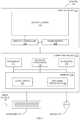
- FIG. 1illustrates a system configured to implement one or more aspects of the present invention.
- system 100includes a display device 110 coupled to a computing device 120 .
- Computing device 120is coupled to input devices 140 that include a keyboard 142 and a mouse 144 .
- Display device 110includes a display screen 112 and a display controller 114 .
- display device 110is an LCD with an LED backlight configured for high dynamic range (HDR) output.
- HDRhigh dynamic range
- Computing device 120includes a processor 122 , a graphics processor 124 , input/output (I/O) devices 126 , and memory 128 , coupled together.
- Processor 122includes any technically feasible set of hardware units configured to process data and execute software applications.
- processor 122could include one or more central processing units (CPUs).
- Graphics processor 124includes any technically feasible set of hardware units configured to process graphics data and execute graphics applications.
- graphics processor 124could include one or more graphics processing units (GPUs).
- I/O devices 126include any technically feasible set of devices configured to perform input and/or output operations, including, for example, a universal serial bus (USB) port, among others.
- Memory 128includes any technically feasible storage media configured to store data and software applications, such as, for example, a hard disk and/or a random-access memory (RAM) module, among others.
- Memory 128includes a device driver 130 and a software application 132 .
- Device driver 130includes program code that is executed by processor 122 to coordinate the operation of graphics processor 124 . During execution, device driver 130 acts as an interface to graphics processor 124 .
- Software application 132includes program code that is executed by processor 122 to generate graphics processing tasks to be performed by graphics processor 124 . In operation, software application 132 transmits these graphics processing tasks to device driver 130 , and device driver 130 generates machine code that can be executed by graphics processor 124 to perform the graphics processing tasks.
- the graphics processing taskscould include, for example, graphics rendering operations, encoding operations, decoding operations, and so forth.
- graphics processor 124When performing graphics rendering operations, graphics processor 124 generates images on behalf of software application 132 and then causes display device 110 to display those images.
- software application 132could be a video game that leverages graphics processor 124 to render images depicting a simulated environment.
- Display device 110could display these images to the user via display screen 112 .
- Display screen 112is described in greater detail below in conjunction with FIG. 2 .
- FIG. 2is a more detailed illustration of the display screen of FIG. 1 , according to various embodiments of the present invention.
- display screen 112includes an LED array 200 that includes a plurality of LEDs 202 .
- LED array 200may be known in the art as a “backlight.”
- Display screen 112also includes an LCD array 220 that includes a plurality of LCD pixels 222 .
- LED array 200is coupled to LCD array 220 and configured to emit light 210 to illuminate LCD array 220 .
- LCD pixels 222are at least partially translucent and therefore allow the re-transmission of any received light.
- Each LCD pixel 222can be configured to filter the red, green, and blue (RGB) color components of light 210 and to then emit light 230 with a desired RGB color mix value.
- RGBred, green, and blue
- FIG. 3is a more detailed illustration of an LCD pixel of FIG. 2 , according to various embodiments of the present invention.
- an LCD pixel 222includes valves 300 ( 0 ), 300 ( 1 ), and 300 ( 2 ).
- a given valve 300controls the amount of red, green, or blue light that is filtered by LCD pixel 222 .
- valve 300 ( 0 )controls the filtering of red light
- valve 300 ( 1 )controls the filtering of green light
- valve 300 ( 2 )controls the filtering of blue light.
- LCD pixel 222receives light 210 from LEDs 202 ( 0 ) through 202 (M).
- LEDs 202 ( 0 ) through 202 (M)include some or all LEDs included in LED array 200 .
- LCD pixel 222filters light 210 and then outputs light 230 having a specific red, green, blue (RGB) color value.
- Display controller 114controls the brightness of LEDs 202 by supplying varying levels of current to each LED 202 .
- display controller 114could cause an LED 202 to output light with an elevated brightness by supplying an elevated current level to that LED.
- Display controller 114controls the color of light emitted by LCD pixel 222 by setting different percentages with which valves 300 should filter red, green, and blue light.
- display controller 114could cause LCD pixel 222 to output a purely blue light by setting valves 300 ( 0 ) and 300 ( 1 ) to filter 100% of red light and 100% of green light and filter 0% of blue light, thereby allowing only the blue component of light 210 to pass through LCD pixel 222 relatively unfiltered.
- display controller 114controls the operation of LEDs 202 and LCD pixels 222 based on the image to be displayed, as described in greater detail below in conjunction with FIG. 4 .
- FIG. 4illustrates how the display controller of FIG. 1 causes an image to be displayed, according to various embodiments of the present invention.
- display controller 114receives some or all of an image 400 from frame buffer 116 and then generates LED current levels 410 and LCD valve settings 420 .
- display controller 114performs an image processing operation with image 400 to determine a target brightness for each LED 202 .
- Display controller 114determines the specific current level that should be supplied to each LED 202 to achieve the target brightness.
- each LED 202outputs light with a specific intensity, or luminance.
- Each LED 202contributes a certain amount of this luminance to LCD pixel 222 .
- LED 202generates a luminance contribution 402 that is received by LCD pixel 222 .
- display controller 114When generating LCD valve settings 420 for image 400 , display controller 114 maps each LCD pixel 222 to a different portion or pixel of image 400 to determine a target RGB color value for each LCD pixel 222 . Display controller 114 also accumulates luminance contributions 402 provided by some or all LEDs 202 to each LCD pixel 222 to generate a backlight illumination field (BLIF).
- the BLIFis an array of values that indicates the total luminance received at each LCD pixel 222 when some or all LEDs 202 emit light based on the target brightness settings. Display controller 114 determines LCD valve settings 420 for LCD pixels 222 by dividing the target RGB color values by corresponding values included in the BLIF.
- display controller 114performs the technique described above progressively while image 400 is being written into frame buffer 116 .
- display controller 114progressively updates LEDs 202 and LCD pixels 222 in scanline order based on progressively received lines of image 400 .
- An advantage of this approachis that display controller 114 avoids introducing a frame delay when displaying image 400 . This approach is described in greater detail below in conjunction with FIG. 5 .
- FIG. 5illustrates how the display controller of FIG. 1 configures an LED and an LCD pixel based on a portion of an image, according to various embodiments.
- display screen 112includes LED 202 that contributes luminance to LCD pixels 222 falling within a region 500 of display screen 112 .
- Region 500is circular and has a radius D.
- LCD pixels 222 ( 0 ) and 222 ( 1 )reside within region 500 .
- LED 202is configured to provide a luminance contribution 402 ( 0 ) to LCD pixel 222 ( 0 ) and to provide a luminance contribution 402 ( 1 ) to LCD pixel 222 ( 1 ).
- LCD pixel 222 ( 0 )generally resides above LED 202 within display screen 112 .
- LCD pixel 222 ( 1 )generally resides below LED 202 within display screen 112 .
- LED 202may be included in a neighborhood of LEDs that surrounds LCD pixel 222 ( 1 ) and collectively provides sufficient luminance to cause LCD pixel 222 ( 1 ) to achieve a desired brightness.
- frame buffer 116includes lines 510 ( 0 ) through 510 (M) of image 400 .
- frame buffer 116progressively receives lines 510 of image 400 from graphics processor 124 in scanline order.
- Each line 510includes pixel values associated with the various LCD pixels 222 included in display screen 112 .
- line 510 ( 0 )could include a pixel value corresponding to LCD pixel 222 ( 0 )
- line 510 (M)could include another pixel value corresponding to LCD pixel 222 ( 1 ).
- the LCD valve setting for a given LCD pixeldepends on the corresponding pixel value as well as the accumulated luminance contributions received from nearby LEDs 202 , as discussed above in conjunction with FIG. 4 . Accordingly, the LCD valve setting for LCD pixel 222 ( 0 ) depends on the corresponding pixel value and luminance contribution 402 ( 0 ) received from LED 202 . Luminance contribution 402 ( 0 ), in turn, depends on the particular LED current setting 410 associated with LED 202 . Display controller 114 determines the LED current setting 410 for LED 202 based, at least in part, on a luminance component of the pixel value associated with LCD pixel 222 ( 1 ).
- Display controller 114would determine that LED 202 should have a correspondingly high current setting 410 in order to contribute an elevated amount of luminance to LCD pixel 222 ( 1 ).
- frame buffer 116receives a line 510 that includes the pixel value corresponding to LCD pixel 222 ( 1 )
- display controller 114computes the LED current setting 410 for LED 202 and computes the LCD valve setting for LCD pixel 222 ( 0 ). Then, display controller updates LED 202 and LCD pixel 222 ( 0 ) based on the computed settings, thereby causing LED 202 ( 0 ) to emit light corresponding to a portion of image 400 . In this manner, display controller 114 is capable of progressively displaying portions of image 400 as those portions are scanned into frame buffer 116 .
- display controller 114begins painting pixels associated with image 400 to display screen 112 as soon as sufficient pixel values are available to do so.
- display controller 114can begin configuring LCD pixel 222 ( 0 ) once the pixel value associated with LCD pixel 222 ( 1 ) is available. Accordingly, display controller 114 avoids introducing a full frame delay and can therefore output image with very low latency.
- display controller 114performs an additional technique to minimize the appearance of visual artifacts, as described in greater detail below in conjunction with FIG. 6 .
- FIG. 6illustrates how the display controller of FIG. 1 coordinates updating an LED with updating a corresponding LCD pixel, according to various embodiments of the present invention.
- a graph 600includes a plot 602 that indicates a valve configuration for an LCD pixel 222 as a function of time.
- Graph 600includes time axis 610 and valve configuration axis 620 .
- display controller 114transitions the valve configuration for the LCD pixel 222 from an initial valve configuration V initial to a final valve configuration V final . The transition occurs during an interval between an initial time T initial and a final time T final . Midway through the transition, at time T mid , the LCD pixel 222 is partially configured.
- a graph 630includes a plot 632 that indicates a current setting for an LED 202 as a function of time.
- Graph 630includes time axis 640 and current setting axis 650 .
- display controller 114transitions the current setting for the LED 202 from an initial current setting C initial to a final current setting C final . The transition occurs within a short subinterval between T initial and T final that is centered around T mid .
- the LCD pixel 222 associated with graph 600 and the LED 202 associated with graph 630reside proximate to one another within display screen 112 .
- the LED 202is configured to illuminate the LCD pixel 222 .
- Display controller 114coordinates configuring the LCD pixel 222 and configuring the LED 202 in order to avoid visual artifacts that can arise when LCD pixels and corresponding LEDs are configured at different times. Specifically, because the LED 202 can be configured much faster than the LCD pixel 222 can be configured, as is shown, display controller 114 initiates configuring the LED 202 when the LCD pixel 222 is about halfway configured (around T mid ). As referred to herein, a configuration may be considered approximately halfway complete when anywhere between 40% and 60% complete.
- display controller 114may configure one or more LEDs 202 that contribute luminance to the LCD pixel 222 when the configuration of a certain number of other LCD pixels 222 is complete. For example, display controller 114 could wait until a first half of the LCD pixels 222 that reside between two rows of LEDs 202 are configured and then configure one of those rows of LEDs 202 to illuminate the first half of the LCD pixels 222 .
- display controller 114may cause LEDs 202 to increase brightness rapidly according to a step function such as that shown in graph 630 , but then subsequently cause those LEDs 202 to decrease brightness slowly with a specified decay rate.
- This approachcan cause display screen 112 to appear more responsive because the brightness of display screen 112 can change rapidly.
- This approachalso reduces or eliminates visual artifacts because decreasing brightness slowly provides the LCD pixels 222 with sufficient time to be configured to emit correct color values.
- display controller 114advantageously allow display controller 114 to output images via display screen 112 with minimal frame delay and minimal visual artifacts. Accordingly, display controller 114 in particular, and display device 110 in general, are especially well-suited to high-performance interactive applications, such as gaming, where images can change rapidly based on user input.
- FIG. 7is a flow diagram of method steps for updating an LED and an LCD pixel based on a portion of an image, according to various embodiments of the present invention.
- the method stepsare described in conjunction with the systems of FIGS. 1-6 , persons skilled in the art will understand that any system configured to perform the method steps in any order falls within the scope of the present invention.
- a method 700begins at step 702 , where frame buffer 116 of FIG. 1 buffers a first portion of an image that includes a first pixel value corresponding to a first LCD pixel.
- frame buffer 116could buffer a line 510 of image 400 that includes a pixel value corresponding to LCD pixel 222 ( 1 ).
- Frame buffer 116may also buffer other portions of image 400 instead of lines, including pixels, for example.
- display controller 114determines that the first pixel value is needed to compute a first LED current setting for a first LED.
- the first LEDprovides significant luminance contributions to LCD pixels within a specific radius around the first LED, including the first LCD pixel.
- the first LED current setting for the first LEDis computed based on the first pixel value. Accordingly, display controller 114 waits until frame buffer 116 includes the first pixel value before computing the first LED current setting for the first LED.
- the first LEDmay reside before the first LCD pixel in a scanline order associated with display screen 112 .
- display controller 114computes the first LED current setting based on the first pixel value.
- the first pixel valuemay indicate that the first LCD pixel should have a maximum brightness level.
- the first LCD pixelcan achieve the maximum brightness level when one or more LEDs near the first LCD pixel collectively provide luminance contributions to the first LCD pixel.
- the first LCD pixelcould achieve the maximum brightness level when a 3 ⁇ 3 neighborhood of LEDs surrounding the first LCD pixel provide luminance contributions to the first LCD pixel.
- display controller 114computes an LCD valve setting for a second LCD pixel that resides above the first LED.
- the second LCD pixelreceives a luminance contribution from the first LED that is based on the first LED current setting computed at step 706 . This luminance contribution influences the computation of the LCD valve setting for the second LCD pixel. Because the first LED current setting depends on the first pixel value associated with the first LCD pixel, display controller 114 can compute the LCD valve setting for the second LCD pixel after the frame buffer stores the first portion of the image at step 702 .
- display controller 114configures the second LCD pixel based on the computed LCD valve setting.
- display controller 114can configure the second LCD pixel before the entire image is scanned into frame buffer 116 , unlike conventional display controllers that introduce a frame delay and wait for the entire image to be scanned into the frame buffer. This approach advantageously allows images to be progressively scanned into the frame buffer and incrementally painted to display device 112 with low latency. Images displayed in this manner may appear more responsive to user input.
- display controller 114determines an update status associated with the second LCD pixel.
- LCD pixelsare configured more slowly than LEDs are configured.
- display controller 114monitors transitioning of the second LCD pixel and determines when the second LCD pixel has at least partially transitioned to the LCD valve setting determined at step 708 and configured at step 710 .
- the second LCD pixeltransitions between LCD valve settings over a first interval of time, and display controller 114 determines the update status to indicate when approximately half of the first interval has occurred.
- display controllerupdates one or more LEDs that illuminate the second LCD pixel based on the update status determined at step 710 .
- display controller 114determines when the second LCD pixel has at least partially transitioned to the LCD valve setting determined and configured via steps 706 and 708 , respectively.
- Display controller 114updates the one or more LEDs that illuminate the second LCD pixel during configuration of the second LCD pixel in order to avoid visual artifacts that may occur when LCD pixels and LEDs are updated or configured at different times.
- a display controllerprogressively updates LEDs and LCD pixels in scanline order as portions of an image are scanned into a frame buffer.
- the display controlleranalyzes a first portion of the image that includes a first pixel value associated with a first LCD pixel.
- the display controlleridentifies a first LED that contributes luminance to the first LCD pixel and determines an LED current setting for the LED based on the first pixel value.
- the display controllerthen identifies a second LCD pixel that resides above the first LED and is associated with a second pixel value.
- the display controllercomputes accumulated luminance contributions at the second LCD pixel from nearby LEDs, including the first LED.
- the display controllerconfigures the second LCD pixel based on the second pixel value and the accumulated luminance contributions.
- the display controllerupdates one or more LEDs associated with the second LCD pixel.
- At least one technological advantage of the disclosed techniques relative to the prior artis that an image scanned into the frame buffer is progressively painted to the display screen without a full frame delay. Accordingly, the disclosed techniques are especially well-suited for gaming applications where the time between user input and graphical response should be minimized.
- Another technological advantage of the disclosed techniques relative to the prior artis that the LEDs are updated in relative synchrony with the LCD pixels, thereby reducing or eliminating the visual artifacts that can arise when LEDs and LCD pixels are updated separately.
- the disclosed display controlleris therefore especially useful for display devices designed for gaming and other high-performance applications.
- Some embodimentsinclude a computer implemented method for displaying an image, the method comprising buffering a first portion of an image that is at least partially scanned into a frame buffer, wherein the first portion of the image includes a first pixel value corresponding to a first screen pixel, computing a first current setting for a first light source based on the first pixel value, wherein the first light source, when illuminated, contributes luminance to both the first screen pixel and to a second screen pixel, and configuring the second screen pixel to emit light based on the first current setting and a second pixel value corresponding to the second screen pixel.
- Some embodimentsinclude a display device, comprising a display screen, and a display controller that causes the display screen to display an image by performing the steps of buffering a first portion of an image that is at least partially scanned into a frame buffer, wherein the first portion of the image includes a first pixel value corresponding to a first screen pixel, computing a first current setting for a first light source based on the first pixel value, wherein the first light source, when illuminated, contributes luminance to both the first screen pixel and to a second screen pixel, and configuring the second screen pixel to emit light based on the first current setting and a second pixel value corresponding to the second screen pixel.
- Some embodimentsinclude a subsystem for displaying an image, the subsystem comprising a frame buffer that buffers a first portion of an image that is at least partially received from a processor, wherein the first portion of the image includes a first pixel value corresponding to a first screen pixel, and a display controller that computes a first current setting for a first light source based on the first pixel value, wherein the first light source, when illuminated, contributes luminance to both the first screen pixel and to a second screen pixel, and configures the second screen pixel to emit light based on the first current setting and a second pixel value corresponding to the second screen pixel.
- aspects of the present embodimentsmay be embodied as a system, method or computer program product. Accordingly, aspects of the present disclosure may take the form of an entirely hardware embodiment, an entirely software embodiment (including firmware, resident software, micro-code, etc.) or an embodiment combining software and hardware aspects that may all generally be referred to herein as a “module” or “system.” Furthermore, aspects of the present disclosure may take the form of a computer program product embodied in one or more computer readable medium(s) having computer readable program code embodied thereon.
- the computer readable mediummay be a computer readable signal medium or a computer readable storage medium.
- a computer readable storage mediummay be, for example, but not limited to, an electronic, magnetic, optical, electromagnetic, infrared, or semiconductor system, apparatus, or device, or any suitable combination of the foregoing.
- a computer readable storage mediummay be any tangible medium that can contain, or store a program for use by or in connection with an instruction execution system, apparatus, or device.
- each block in the flowchart or block diagramsmay represent a module, segment, or portion of code, which comprises one or more executable instructions for implementing the specified logical function(s).
- the functions noted in the blockmay occur out of the order noted in the figures. For example, two blocks shown in succession may, in fact, be executed substantially concurrently, or the blocks may sometimes be executed in the reverse order, depending upon the functionality involved.
Landscapes
- Engineering & Computer Science (AREA)
- Physics & Mathematics (AREA)
- Computer Hardware Design (AREA)
- General Physics & Mathematics (AREA)
- Theoretical Computer Science (AREA)
- Chemical & Material Sciences (AREA)
- Crystallography & Structural Chemistry (AREA)
- Control Of Indicators Other Than Cathode Ray Tubes (AREA)
Abstract
Description
Claims (20)
Priority Applications (1)
| Application Number | Priority Date | Filing Date | Title |
|---|---|---|---|
| US16/268,438US11043172B2 (en) | 2018-02-27 | 2019-02-05 | Low-latency high-dynamic range liquid-crystal display device |
Applications Claiming Priority (2)
| Application Number | Priority Date | Filing Date | Title |
|---|---|---|---|
| US201862636130P | 2018-02-27 | 2018-02-27 | |
| US16/268,438US11043172B2 (en) | 2018-02-27 | 2019-02-05 | Low-latency high-dynamic range liquid-crystal display device |
Publications (2)
| Publication Number | Publication Date |
|---|---|
| US20190266961A1 US20190266961A1 (en) | 2019-08-29 |
| US11043172B2true US11043172B2 (en) | 2021-06-22 |
Family
ID=67684613
Family Applications (1)
| Application Number | Title | Priority Date | Filing Date |
|---|---|---|---|
| US16/268,438ActiveUS11043172B2 (en) | 2018-02-27 | 2019-02-05 | Low-latency high-dynamic range liquid-crystal display device |
Country Status (1)
| Country | Link |
|---|---|
| US (1) | US11043172B2 (en) |
Families Citing this family (6)
| Publication number | Priority date | Publication date | Assignee | Title |
|---|---|---|---|---|
| US10909903B2 (en) | 2018-02-27 | 2021-02-02 | Nvidia Corporation | Parallel implementation of a dithering algorithm for high data rate display devices |
| US10607552B2 (en)* | 2018-02-27 | 2020-03-31 | Nvidia Corporation | Parallel pipelines for computing backlight illumination fields in high dynamic range display devices |
| US11238815B2 (en) | 2018-02-27 | 2022-02-01 | Nvidia Corporation | Techniques for updating light-emitting diodes in synchrony with liquid-crystal display pixel refresh |
| US11776490B2 (en) | 2018-02-27 | 2023-10-03 | Nvidia Corporation | Techniques for improving the color accuracy of light-emitting diodes in backlit liquid-crystal displays |
| US11043172B2 (en) | 2018-02-27 | 2021-06-22 | Nvidia Corporation | Low-latency high-dynamic range liquid-crystal display device |
| US11694643B2 (en)* | 2021-06-02 | 2023-07-04 | Nvidia Corporation | Low latency variable backlight liquid crystal display system |
Citations (53)
| Publication number | Priority date | Publication date | Assignee | Title |
|---|---|---|---|---|
| US5931960A (en) | 1997-10-31 | 1999-08-03 | Xerox Corporation | Method and apparatus for handling error diffusion values |
| US20020019970A1 (en) | 2000-06-01 | 2002-02-14 | Kenji Araki | System for checking wiring configuration of printed circuit board |
| US6359662B1 (en) | 1999-11-05 | 2002-03-19 | Agilent Technologies, Inc. | Method and system for compensating for defects in a multi-light valve display system |
| US6633301B1 (en) | 1999-05-17 | 2003-10-14 | Displaytech, Inc. | RGB illuminator with calibration via single detector servo |
| US20050073845A1 (en) | 2002-12-05 | 2005-04-07 | Olympus Corporation | Display apparatus, light source device, and illumination unit |
| US20060077489A1 (en) | 2004-08-20 | 2006-04-13 | Xerox Corporation | Uniformity compensation in halftoned images |
| US20060107616A1 (en) | 2004-10-08 | 2006-05-25 | Carlo Ratti | Programmable window: a device for controlling the opacity of small-scale areas within a large scale transparent membrane |
| US20060279522A1 (en) | 2002-12-09 | 2006-12-14 | Hitachi Displays, Ltd. | Liquid crystal display device |
| US20070027651A1 (en) | 2005-07-27 | 2007-02-01 | Ng Joh J | System and method for a color sensor |
| US20070211014A1 (en) | 2006-03-10 | 2007-09-13 | Hyoung-Rae Kim | Methods and Circuits for Synchronous Operation of Display Backlighting |
| US20070268695A1 (en) | 2004-12-23 | 2007-11-22 | Dolby Canada Corporation | Wide color gamut displays |
| US20090033612A1 (en) | 2007-07-31 | 2009-02-05 | Roberts John K | Correction of temperature induced color drift in solid state lighting displays |
| US20090174638A1 (en) | 2006-06-02 | 2009-07-09 | Samsung Electronics Co., Ltd. | High Dynamic Contrast Display System Having Multiple Segmented Backlight |
| US20100110112A1 (en) | 2008-10-28 | 2010-05-06 | Panasonic Corporation | Backlight apparatus and display apparatus |
| US20100134512A1 (en) | 2008-12-01 | 2010-06-03 | Yong-Hoon Kwon | Liquid crystal display device and method of driving the same |
| US20100134406A1 (en) | 2008-11-28 | 2010-06-03 | Hitachi Displays, Ltd. | Backlight device and display device |
| US20100171690A1 (en) | 2009-01-06 | 2010-07-08 | Samsung Electronics Co., Ltd. | Method for driving a light source and light source apparatus for performing the method |
| US20100225574A1 (en) | 2008-01-31 | 2010-09-09 | Kohji Fujiwara | Image display device and image display method |
| US20100253706A1 (en)* | 2009-03-18 | 2010-10-07 | Panasonic Corporation | Organic light emitting display device and control method thereof |
| US20100295879A1 (en)* | 2009-05-19 | 2010-11-25 | Hitachi Consumer Electronics Co., Ltd. | Image display apparatus |
| US7843402B2 (en) | 2004-09-08 | 2010-11-30 | Nippon Telegraph And Telephone Corporation | 3D displaying method, device and program |
| US20100315445A1 (en) | 2009-06-15 | 2010-12-16 | An Byunghyun | Display device |
| US20110050760A1 (en) | 2009-07-02 | 2011-03-03 | Panasonic Corporation | Image display apparatus and control apparatus and integrated circuit thereof |
| US20110069095A1 (en) | 2009-09-21 | 2011-03-24 | Samsung Electronics Co., Ltd | Display apparatus and method of driving the same |
| US20110096249A1 (en) | 2009-09-24 | 2011-04-28 | Nxp B.V. | Method for processing video data for a liquid crystal display |
| US20110122170A1 (en) | 2009-11-23 | 2011-05-26 | Dongwoo Kim | Method of compensating for pixel data and liquid crystal display |
| US20110141077A1 (en) | 2009-12-11 | 2011-06-16 | Cho Dae-Ho | Driving method for local dimming of liquid crystal display device and apparatus using the same |
| US20110193896A1 (en) | 2008-10-14 | 2011-08-11 | Dolby Laboratories Licensing Corporation | Backlight Simulation at Reduced Resolutions to Determine Spatial Modulation of Light for High Dynamic Range Images |
| US20110205259A1 (en) | 2008-10-28 | 2011-08-25 | Pixtronix, Inc. | System and method for selecting display modes |
| US8059070B2 (en) | 2008-05-28 | 2011-11-15 | Panasonic Corporation | Display device, and methods for manufacturing and controlling the display device |
| US20120051635A1 (en) | 2009-05-11 | 2012-03-01 | Dolby Laboratories Licensing Corporation | Light Detection, Color Appearance Models, and Modifying Dynamic Range for Image Display |
| US20120075555A1 (en) | 2009-06-03 | 2012-03-29 | Parker Jeffery R | Liquid crystal display apparatus and light emitting assembly with light transmission control elements for illuminating same |
| US20120093430A1 (en) | 2010-10-14 | 2012-04-19 | Naoki Sumi | Image processing method and device |
| US20120105509A1 (en) | 2009-07-01 | 2012-05-03 | Panasonic Corporation | Image display device, control device for same, and integrated circuit |
| US20120154462A1 (en) | 2010-12-17 | 2012-06-21 | Kevin Hempson | Regulation of gamma characteristic in a display |
| US20120154459A1 (en) | 2009-09-30 | 2012-06-21 | Sharp Kabushiki Kaisha | Image display device and image display method |
| US20130010016A1 (en) | 2010-03-24 | 2013-01-10 | Sharp Kabushiki Kaisha | Display panel driving method, display device driving circuit, and display device |
| US20130314459A1 (en) | 2011-02-23 | 2013-11-28 | Atsushi Nakanishi | Display device and display method |
| US20140327710A1 (en) | 2013-05-06 | 2014-11-06 | Dolby Laboratories Licensing Corporation | Systems and Methods for Increasing Spatial or Temporal Resolution for Dual Modulated Display Systems |
| US20150070403A1 (en) | 2013-09-11 | 2015-03-12 | Samsung Display Co., Ltd. | Method of driving a display panel,display apparatus performing the same, method of determining a correction value applied to the same, and method of correcting grayscale data |
| US20150116378A1 (en) | 2013-10-24 | 2015-04-30 | Samsung Display Co., Ltd. | Display apparatus and driving method thereof |
| US20160225301A1 (en) | 2015-02-02 | 2016-08-04 | Apple Inc. | Adjustable display illumination |
| US20160344992A1 (en) | 2015-05-20 | 2016-11-24 | Arthrex, Inc. | Adaptive camera white balance system and method |
| US20170132972A1 (en) | 2015-11-11 | 2017-05-11 | Joled Inc. | Display device, display device correction method, display device manufacturing method, and display device display method |
| US20170223786A1 (en) | 2016-01-28 | 2017-08-03 | Ecosense Lighting Inc | Systems for providing tunable white light with high color rendering |
| US20180277059A1 (en) | 2017-03-22 | 2018-09-27 | Canon Kabushiki Kaisha | Display apparatus and control method thereof |
| US20180302651A1 (en) | 2017-04-12 | 2018-10-18 | Qualcomm Incorporated | Midpoint prediction error diffusion for display stream compression |
| US20180336397A1 (en) | 2017-05-17 | 2018-11-22 | Tandent Vision Science, Inc. | Method for detecting a live face for access to an electronic device |
| US20190107626A1 (en) | 2016-06-08 | 2019-04-11 | Panasonic Intellectual Property Management Co., Ltd. | Distance-measuring system and distance-measuring method |
| US20190188917A1 (en) | 2017-12-20 | 2019-06-20 | Eaton Intelligent Power Limited | Lighting And Internet Of Things Design Using Augmented Reality |
| US20190266959A1 (en) | 2018-02-27 | 2019-08-29 | Nvidia Corporation | Techniques for improving the color accuracy of light-emitting diodes in backlit liquid-crystal displays |
| US20190266935A1 (en) | 2018-02-27 | 2019-08-29 | Nvidia Corporation | Parallel implementation of a dithering algorithm for high data rate display devices |
| US20190266961A1 (en) | 2018-02-27 | 2019-08-29 | Nvidia Corporation | Low-latency high-dynamic range liquid-crystal display device |
- 2019
- 2019-02-05USUS16/268,438patent/US11043172B2/enactiveActive
Patent Citations (53)
| Publication number | Priority date | Publication date | Assignee | Title |
|---|---|---|---|---|
| US5931960A (en) | 1997-10-31 | 1999-08-03 | Xerox Corporation | Method and apparatus for handling error diffusion values |
| US6633301B1 (en) | 1999-05-17 | 2003-10-14 | Displaytech, Inc. | RGB illuminator with calibration via single detector servo |
| US6359662B1 (en) | 1999-11-05 | 2002-03-19 | Agilent Technologies, Inc. | Method and system for compensating for defects in a multi-light valve display system |
| US20020019970A1 (en) | 2000-06-01 | 2002-02-14 | Kenji Araki | System for checking wiring configuration of printed circuit board |
| US20050073845A1 (en) | 2002-12-05 | 2005-04-07 | Olympus Corporation | Display apparatus, light source device, and illumination unit |
| US20060279522A1 (en) | 2002-12-09 | 2006-12-14 | Hitachi Displays, Ltd. | Liquid crystal display device |
| US20060077489A1 (en) | 2004-08-20 | 2006-04-13 | Xerox Corporation | Uniformity compensation in halftoned images |
| US7843402B2 (en) | 2004-09-08 | 2010-11-30 | Nippon Telegraph And Telephone Corporation | 3D displaying method, device and program |
| US20060107616A1 (en) | 2004-10-08 | 2006-05-25 | Carlo Ratti | Programmable window: a device for controlling the opacity of small-scale areas within a large scale transparent membrane |
| US20070268695A1 (en) | 2004-12-23 | 2007-11-22 | Dolby Canada Corporation | Wide color gamut displays |
| US20070027651A1 (en) | 2005-07-27 | 2007-02-01 | Ng Joh J | System and method for a color sensor |
| US20070211014A1 (en) | 2006-03-10 | 2007-09-13 | Hyoung-Rae Kim | Methods and Circuits for Synchronous Operation of Display Backlighting |
| US20090174638A1 (en) | 2006-06-02 | 2009-07-09 | Samsung Electronics Co., Ltd. | High Dynamic Contrast Display System Having Multiple Segmented Backlight |
| US20090033612A1 (en) | 2007-07-31 | 2009-02-05 | Roberts John K | Correction of temperature induced color drift in solid state lighting displays |
| US20100225574A1 (en) | 2008-01-31 | 2010-09-09 | Kohji Fujiwara | Image display device and image display method |
| US8059070B2 (en) | 2008-05-28 | 2011-11-15 | Panasonic Corporation | Display device, and methods for manufacturing and controlling the display device |
| US20110193896A1 (en) | 2008-10-14 | 2011-08-11 | Dolby Laboratories Licensing Corporation | Backlight Simulation at Reduced Resolutions to Determine Spatial Modulation of Light for High Dynamic Range Images |
| US20100110112A1 (en) | 2008-10-28 | 2010-05-06 | Panasonic Corporation | Backlight apparatus and display apparatus |
| US20110205259A1 (en) | 2008-10-28 | 2011-08-25 | Pixtronix, Inc. | System and method for selecting display modes |
| US20100134406A1 (en) | 2008-11-28 | 2010-06-03 | Hitachi Displays, Ltd. | Backlight device and display device |
| US20100134512A1 (en) | 2008-12-01 | 2010-06-03 | Yong-Hoon Kwon | Liquid crystal display device and method of driving the same |
| US20100171690A1 (en) | 2009-01-06 | 2010-07-08 | Samsung Electronics Co., Ltd. | Method for driving a light source and light source apparatus for performing the method |
| US20100253706A1 (en)* | 2009-03-18 | 2010-10-07 | Panasonic Corporation | Organic light emitting display device and control method thereof |
| US20120051635A1 (en) | 2009-05-11 | 2012-03-01 | Dolby Laboratories Licensing Corporation | Light Detection, Color Appearance Models, and Modifying Dynamic Range for Image Display |
| US20100295879A1 (en)* | 2009-05-19 | 2010-11-25 | Hitachi Consumer Electronics Co., Ltd. | Image display apparatus |
| US20120075555A1 (en) | 2009-06-03 | 2012-03-29 | Parker Jeffery R | Liquid crystal display apparatus and light emitting assembly with light transmission control elements for illuminating same |
| US20100315445A1 (en) | 2009-06-15 | 2010-12-16 | An Byunghyun | Display device |
| US20120105509A1 (en) | 2009-07-01 | 2012-05-03 | Panasonic Corporation | Image display device, control device for same, and integrated circuit |
| US20110050760A1 (en) | 2009-07-02 | 2011-03-03 | Panasonic Corporation | Image display apparatus and control apparatus and integrated circuit thereof |
| US20110069095A1 (en) | 2009-09-21 | 2011-03-24 | Samsung Electronics Co., Ltd | Display apparatus and method of driving the same |
| US20110096249A1 (en) | 2009-09-24 | 2011-04-28 | Nxp B.V. | Method for processing video data for a liquid crystal display |
| US20120154459A1 (en) | 2009-09-30 | 2012-06-21 | Sharp Kabushiki Kaisha | Image display device and image display method |
| US20110122170A1 (en) | 2009-11-23 | 2011-05-26 | Dongwoo Kim | Method of compensating for pixel data and liquid crystal display |
| US20110141077A1 (en) | 2009-12-11 | 2011-06-16 | Cho Dae-Ho | Driving method for local dimming of liquid crystal display device and apparatus using the same |
| US20130010016A1 (en) | 2010-03-24 | 2013-01-10 | Sharp Kabushiki Kaisha | Display panel driving method, display device driving circuit, and display device |
| US20120093430A1 (en) | 2010-10-14 | 2012-04-19 | Naoki Sumi | Image processing method and device |
| US20120154462A1 (en) | 2010-12-17 | 2012-06-21 | Kevin Hempson | Regulation of gamma characteristic in a display |
| US20130314459A1 (en) | 2011-02-23 | 2013-11-28 | Atsushi Nakanishi | Display device and display method |
| US20140327710A1 (en) | 2013-05-06 | 2014-11-06 | Dolby Laboratories Licensing Corporation | Systems and Methods for Increasing Spatial or Temporal Resolution for Dual Modulated Display Systems |
| US20150070403A1 (en) | 2013-09-11 | 2015-03-12 | Samsung Display Co., Ltd. | Method of driving a display panel,display apparatus performing the same, method of determining a correction value applied to the same, and method of correcting grayscale data |
| US20150116378A1 (en) | 2013-10-24 | 2015-04-30 | Samsung Display Co., Ltd. | Display apparatus and driving method thereof |
| US20160225301A1 (en) | 2015-02-02 | 2016-08-04 | Apple Inc. | Adjustable display illumination |
| US20160344992A1 (en) | 2015-05-20 | 2016-11-24 | Arthrex, Inc. | Adaptive camera white balance system and method |
| US20170132972A1 (en) | 2015-11-11 | 2017-05-11 | Joled Inc. | Display device, display device correction method, display device manufacturing method, and display device display method |
| US20170223786A1 (en) | 2016-01-28 | 2017-08-03 | Ecosense Lighting Inc | Systems for providing tunable white light with high color rendering |
| US20190107626A1 (en) | 2016-06-08 | 2019-04-11 | Panasonic Intellectual Property Management Co., Ltd. | Distance-measuring system and distance-measuring method |
| US20180277059A1 (en) | 2017-03-22 | 2018-09-27 | Canon Kabushiki Kaisha | Display apparatus and control method thereof |
| US20180302651A1 (en) | 2017-04-12 | 2018-10-18 | Qualcomm Incorporated | Midpoint prediction error diffusion for display stream compression |
| US20180336397A1 (en) | 2017-05-17 | 2018-11-22 | Tandent Vision Science, Inc. | Method for detecting a live face for access to an electronic device |
| US20190188917A1 (en) | 2017-12-20 | 2019-06-20 | Eaton Intelligent Power Limited | Lighting And Internet Of Things Design Using Augmented Reality |
| US20190266959A1 (en) | 2018-02-27 | 2019-08-29 | Nvidia Corporation | Techniques for improving the color accuracy of light-emitting diodes in backlit liquid-crystal displays |
| US20190266935A1 (en) | 2018-02-27 | 2019-08-29 | Nvidia Corporation | Parallel implementation of a dithering algorithm for high data rate display devices |
| US20190266961A1 (en) | 2018-02-27 | 2019-08-29 | Nvidia Corporation | Low-latency high-dynamic range liquid-crystal display device |
Non-Patent Citations (18)
| Title |
|---|
| Ex-Parte Quayle Action received for U.S. Appl. No. 16/276,564, dated Mar. 31, 2020, 16 pages. |
| Final Office Action received for U.S. Appl. No. 16/163,515 dated Aug. 28, 2020, 37 pages. |
| Final Office Action received for U.S. Appl. No. 16/163,516 dated Jun. 1, 2020, 30 pages. |
| Final Office Action received for U.S. Appl. No. 16/271,743 dated Oct. 14, 2020, 29 pages. |
| Non-Final Office Action received for U.S. Appl. No. 16/163,515, dated Mar. 3, 2020, 40 pages. |
| Non-Final Office Action received for U.S. Appl. No. 16/163,516 dated Dec. 16, 2020, 32 pages. |
| Non-Final Office Action received for U.S. Appl. No. 16/163,516 dated Nov. 19, 2019, 22 pages. |
| Non-Final Office Action received for U.S. Appl. No. 16/163,516 dated Sep. 24, 2020, 54 pages. |
| Non-Final Office Action received for U.S. Appl. No. 16/271,743 dated Feb. 19, 2021, 28 pages. |
| Non-Final Office Action received for U.S. Appl. No. 16/271,743 dated Jun. 22, 2020, 36 pages. |
| Non-Final Office Action received for U.S. Appl. No. 16/828,850, dated Nov. 24, 2020, 38 pages. |
| Non-Final Office Action received for U.S. Appl. No. 16/828,850, dated Nov. 24, 2020, 50 pages. |
| Notice of Allowance for U.S. Appl. No. 16/152,358, dated Nov. 20, 2019, 12 pages. |
| Notice of Allowance received for U.S. Appl. No. 16/271,744, dated Mar. 17, 2020, 28 pages. |
| Notice of Allowance received for U.S. Appl. No. 16/276,564, dated Jul. 7, 2020, 46 pages. |
| Notice of Allowance received for U.S. Appl. No. 16/276,564, dated Nov. 12, 2020, 6 pages. |
| Notice of Allowance received for U.S. Appl. No. 16/276,564, dated Sep. 11, 2020, 33 pages. |
| Notice of Allowance received for U.S. Appl. No. 16/276,564, dated Sep. 23, 2020, 5 pages. |
Also Published As
| Publication number | Publication date |
|---|---|
| US20190266961A1 (en) | 2019-08-29 |
Similar Documents
| Publication | Publication Date | Title |
|---|---|---|
| US11043172B2 (en) | Low-latency high-dynamic range liquid-crystal display device | |
| CN108538260B (en) | Image display processing method and device, display device and storage medium | |
| US11521564B2 (en) | Image display processing method and device, display device and non-volatile storage medium | |
| CN113272883B (en) | Viewing angle dependent color/brightness correction for display systems | |
| US11244636B2 (en) | Display device comprising backlight unit with backlight blocks in rows driven by local dimming method | |
| CN111899694B (en) | Backlight control method and device of backlight module, and display device | |
| CN108766364B (en) | Image display processing method and device, display device and storage medium | |
| US10600387B2 (en) | Display apparatus and method for driving a backlight to prevent or reduce gradation overcompensation | |
| US8872732B2 (en) | Multi-display system with backlight intensity correction | |
| US10726797B2 (en) | Techniques for updating light-emitting diodes in synchrony with liquid-crystal display pixel refresh | |
| US11776490B2 (en) | Techniques for improving the color accuracy of light-emitting diodes in backlit liquid-crystal displays | |
| KR102599950B1 (en) | Electronic device and control method thereof | |
| JP6281985B2 (en) | Transparent display device | |
| JP2021536031A (en) | Display rescan | |
| US10462336B2 (en) | Low latency tearing without user perception | |
| US20170075432A1 (en) | Cursor handling in a variable refresh rate environment | |
| US11232739B2 (en) | Electronic device, color adjustment method, and computer-readable recording medium | |
| KR102735461B1 (en) | Electronic apparatus and control method thereof | |
| US11074871B2 (en) | Parallel pipelines for computing backlight illumination fields in high dynamic range display devices | |
| US20190096341A1 (en) | Method, system and computer readable storage medium for driving liquid crystal displays | |
| US20250233965A1 (en) | Projection apparatus and projection method | |
| US20250246158A1 (en) | Methods and apparatus to control backlight drivers | |
| KR20240111068A (en) | Apparatus And Method For Driving A Display Panel | |
| TWI625716B (en) | Method and device for saving power consumption of panel | |
| TWM445702U (en) | LED backlight dynamic control device |
Legal Events
| Date | Code | Title | Description |
|---|---|---|---|
| FEPP | Fee payment procedure | Free format text:ENTITY STATUS SET TO UNDISCOUNTED (ORIGINAL EVENT CODE: BIG.); ENTITY STATUS OF PATENT OWNER: LARGE ENTITY | |
| AS | Assignment | Owner name:NVIDIA CORPORATION, CALIFORNIA Free format text:ASSIGNMENT OF ASSIGNORS INTEREST;ASSIGNORS:SLAVENBURG, GERRIT ARY;SCHUTTEN, ROBERT JAN;ROEVER, JENS;AND OTHERS;REEL/FRAME:050068/0904 Effective date:20190205 | |
| STPP | Information on status: patent application and granting procedure in general | Free format text:NON FINAL ACTION MAILED | |
| STPP | Information on status: patent application and granting procedure in general | Free format text:FINAL REJECTION MAILED | |
| STPP | Information on status: patent application and granting procedure in general | Free format text:RESPONSE AFTER FINAL ACTION FORWARDED TO EXAMINER | |
| STPP | Information on status: patent application and granting procedure in general | Free format text:ADVISORY ACTION MAILED | |
| STPP | Information on status: patent application and granting procedure in general | Free format text:DOCKETED NEW CASE - READY FOR EXAMINATION | |
| STPP | Information on status: patent application and granting procedure in general | Free format text:NOTICE OF ALLOWANCE MAILED -- APPLICATION RECEIVED IN OFFICE OF PUBLICATIONS | |
| STPP | Information on status: patent application and granting procedure in general | Free format text:NOTICE OF ALLOWANCE MAILED -- APPLICATION RECEIVED IN OFFICE OF PUBLICATIONS | |
| STPP | Information on status: patent application and granting procedure in general | Free format text:AWAITING TC RESP., ISSUE FEE NOT PAID | |
| STPP | Information on status: patent application and granting procedure in general | Free format text:AWAITING TC RESP, ISSUE FEE PAYMENT RECEIVED | |
| STPP | Information on status: patent application and granting procedure in general | Free format text:PUBLICATIONS -- ISSUE FEE PAYMENT VERIFIED | |
| STCF | Information on status: patent grant | Free format text:PATENTED CASE | |
| MAFP | Maintenance fee payment | Free format text:PAYMENT OF MAINTENANCE FEE, 4TH YEAR, LARGE ENTITY (ORIGINAL EVENT CODE: M1551); ENTITY STATUS OF PATENT OWNER: LARGE ENTITY Year of fee payment:4 |