US11042762B2 - Sensor calibration method and device, computer device, medium, and vehicle - Google Patents
Sensor calibration method and device, computer device, medium, and vehicleDownload PDFInfo
- Publication number
- US11042762B2 US11042762B2US16/574,995US201916574995AUS11042762B2US 11042762 B2US11042762 B2US 11042762B2US 201916574995 AUS201916574995 AUS 201916574995AUS 11042762 B2US11042762 B2US 11042762B2
- Authority
- US
- United States
- Prior art keywords
- camera
- lidar
- static object
- coordinate
- surrounding objects
- Prior art date
- Legal status (The legal status is an assumption and is not a legal conclusion. Google has not performed a legal analysis and makes no representation as to the accuracy of the status listed.)
- Active, expires
Links
Images


Classifications
- G06K9/00805—
- G—PHYSICS
- G01—MEASURING; TESTING
- G01S—RADIO DIRECTION-FINDING; RADIO NAVIGATION; DETERMINING DISTANCE OR VELOCITY BY USE OF RADIO WAVES; LOCATING OR PRESENCE-DETECTING BY USE OF THE REFLECTION OR RERADIATION OF RADIO WAVES; ANALOGOUS ARRANGEMENTS USING OTHER WAVES
- G01S13/00—Systems using the reflection or reradiation of radio waves, e.g. radar systems; Analogous systems using reflection or reradiation of waves whose nature or wavelength is irrelevant or unspecified
- G01S13/88—Radar or analogous systems specially adapted for specific applications
- G01S13/93—Radar or analogous systems specially adapted for specific applications for anti-collision purposes
- G01S13/931—Radar or analogous systems specially adapted for specific applications for anti-collision purposes of land vehicles
- G—PHYSICS
- G01—MEASURING; TESTING
- G01S—RADIO DIRECTION-FINDING; RADIO NAVIGATION; DETERMINING DISTANCE OR VELOCITY BY USE OF RADIO WAVES; LOCATING OR PRESENCE-DETECTING BY USE OF THE REFLECTION OR RERADIATION OF RADIO WAVES; ANALOGOUS ARRANGEMENTS USING OTHER WAVES
- G01S17/00—Systems using the reflection or reradiation of electromagnetic waves other than radio waves, e.g. lidar systems
- G01S17/86—Combinations of lidar systems with systems other than lidar, radar or sonar, e.g. with direction finders
- G—PHYSICS
- G01—MEASURING; TESTING
- G01S—RADIO DIRECTION-FINDING; RADIO NAVIGATION; DETERMINING DISTANCE OR VELOCITY BY USE OF RADIO WAVES; LOCATING OR PRESENCE-DETECTING BY USE OF THE REFLECTION OR RERADIATION OF RADIO WAVES; ANALOGOUS ARRANGEMENTS USING OTHER WAVES
- G01S13/00—Systems using the reflection or reradiation of radio waves, e.g. radar systems; Analogous systems using reflection or reradiation of waves whose nature or wavelength is irrelevant or unspecified
- G01S13/86—Combinations of radar systems with non-radar systems, e.g. sonar, direction finder
- G01S13/865—Combination of radar systems with lidar systems
- G—PHYSICS
- G01—MEASURING; TESTING
- G01S—RADIO DIRECTION-FINDING; RADIO NAVIGATION; DETERMINING DISTANCE OR VELOCITY BY USE OF RADIO WAVES; LOCATING OR PRESENCE-DETECTING BY USE OF THE REFLECTION OR RERADIATION OF RADIO WAVES; ANALOGOUS ARRANGEMENTS USING OTHER WAVES
- G01S7/00—Details of systems according to groups G01S13/00, G01S15/00, G01S17/00
- G01S7/02—Details of systems according to groups G01S13/00, G01S15/00, G01S17/00 of systems according to group G01S13/00
- G01S7/40—Means for monitoring or calibrating
- G—PHYSICS
- G01—MEASURING; TESTING
- G01S—RADIO DIRECTION-FINDING; RADIO NAVIGATION; DETERMINING DISTANCE OR VELOCITY BY USE OF RADIO WAVES; LOCATING OR PRESENCE-DETECTING BY USE OF THE REFLECTION OR RERADIATION OF RADIO WAVES; ANALOGOUS ARRANGEMENTS USING OTHER WAVES
- G01S7/00—Details of systems according to groups G01S13/00, G01S15/00, G01S17/00
- G01S7/48—Details of systems according to groups G01S13/00, G01S15/00, G01S17/00 of systems according to group G01S17/00
- G01S7/497—Means for monitoring or calibrating
- G01S7/4972—Alignment of sensor
- G—PHYSICS
- G06—COMPUTING OR CALCULATING; COUNTING
- G06F—ELECTRIC DIGITAL DATA PROCESSING
- G06F18/00—Pattern recognition
- G06F18/20—Analysing
- G06F18/21—Design or setup of recognition systems or techniques; Extraction of features in feature space; Blind source separation
- G06K9/6217—
- G—PHYSICS
- G06—COMPUTING OR CALCULATING; COUNTING
- G06T—IMAGE DATA PROCESSING OR GENERATION, IN GENERAL
- G06T7/00—Image analysis
- G06T7/10—Segmentation; Edge detection
- G06T7/12—Edge-based segmentation
- G—PHYSICS
- G06—COMPUTING OR CALCULATING; COUNTING
- G06T—IMAGE DATA PROCESSING OR GENERATION, IN GENERAL
- G06T7/00—Image analysis
- G06T7/80—Analysis of captured images to determine intrinsic or extrinsic camera parameters, i.e. camera calibration
- G—PHYSICS
- G06—COMPUTING OR CALCULATING; COUNTING
- G06V—IMAGE OR VIDEO RECOGNITION OR UNDERSTANDING
- G06V20/00—Scenes; Scene-specific elements
- G06V20/50—Context or environment of the image
- G06V20/56—Context or environment of the image exterior to a vehicle by using sensors mounted on the vehicle
- G06V20/58—Recognition of moving objects or obstacles, e.g. vehicles or pedestrians; Recognition of traffic objects, e.g. traffic signs, traffic lights or roads
Definitions
- the present disclosurerelates to the field of computer technologies, and more particularly, to a sensor calibration method, a sensor calibration device, a computer device, a storage medium, and a vehicle.
- cameras and lidarsare important components in the autonomous driving system, and can be used to perceive the surrounding environment of the vehicle, such as lane line detection, road tooth detection, obstacle detection, and traffic sign recognition. Considering the respective characteristics of the camera and the lidar, the perception during the autonomous driving can be better accomplished by using the camera and the lidar in combination.
- Embodiments of an aspect of the present disclosureprovide a sensor calibration method, including: detecting surrounding objects in a travelling process of a vehicle; recognizing a static object from the surrounding objects; performing feature extraction on the static object by a camera and a lidar, respectively; and calibrating an extrinsic parameter of the camera and the lidar based on the extracted feature.
- Embodiments of another aspect of the present disclosureprovide a computer device.
- the computer deviceincludes one or more processors, and a storage device configured to store one or more programs.
- the one or more processorsare caused to implement the sensor calibration method according to any embodiment of the present disclosure.
- Embodiments of another aspect of the present disclosureprovide a computer storage medium having stored thereon a computer program that, when executed by a processor, causes the sensor calibration method according to any embodiment of the present disclosure to be implemented.
- Embodiments of yet another aspect of the present disclosureprovide a vehicle.
- the vehicleincludes a vehicle body, the computer device according to an embodiment of the present disclosure, and at least two sensors disposed on the vehicle body.
- the at least two sensorsinclude a lidar and a camera, and the at least two sensors respectively communicate with the computer device.
- FIG. 1is a flow chart of a sensor calibration method according to Embodiment 1 of the present disclosure
- FIG. 2is a flow chart of a sensor calibration method according to Embodiment 2 of the present disclosure
- FIG. 3is a schematic diagram of a sensor calibration device according to Embodiment 3 of the present disclosure.
- FIG. 4is a schematic diagram of a computer device according to Embodiment 4 of the present disclosure.
- the extrinsic parameter calibration of the camera and the lidarcan affect the accuracy of the results produced, which makes it an important part of the autonomous driving technology.
- the extrinsic parameter calibration from the camera to the lidaroften requires a special calibration object or is completed in a calibration room, the operation is complex, and the vehicle is required to be regularly returned to the factory for calibration, making it unsuitable for automatic calibration in driving process. Therefore, when the data acquired by the camera and the lidar are greatly deviated due to looseness of the camera and the lidar in the driving process, the rapid adaptive calibration of the camera and the lidar will be of great significance for autonomous driving.
- FIG. 1is a flow chart of a sensor calibration method according to Embodiment 1 of the present disclosure.
- the embodimentmay be applicable to the case of calibrating a sensor, the method may be performed by a sensor calibration device, which can be implemented by means of software and/or hardware, and can be configured on a computing device.
- the computing devicemay be configured on a vehicle, such as an unmanned vehicle with control and computing capabilities. As shown in FIG. 1 , the method may include the following operations.
- surrounding objectsare detected in a travelling process of a vehicle.
- the surrounding objectmay be detected according to data acquired by sensors configured on the vehicle for sensing objects around the vehicle (such as a camera, a lidar, etc.), and in combination with an object recognition method.
- sensorsconfigured on the vehicle for sensing objects around the vehicle (such as a camera, a lidar, etc.), and in combination with an object recognition method.
- the surrounding objectsmay be determined according to the detection result of a sensor. For example, when there are few dynamic objects in the surrounding environment, the image captured by the camera may be used as input of a pre-trained obstacle recognition model, to detect the type of objects in the surrounding environment of the vehicle. When there are more dynamic objects in the surrounding environment, the three-dimensional (3D) scene construction may be performed based on point cloud data, to detect the type of objects in the surrounding environment of the vehicle.
- detecting the surrounding objectsmay include acts of: performing obstacle detection by the camera and the lidar, respectively; performing verification on an obstacle detection result of the camera and an obstacle detection result of the lidar, to obtain a final obstacle detection result; and determining the surrounding objects based on the final obstacle detection result.
- the obstaclemay be an object outside the vehicle in the surrounding environment.
- a fine classification of obstaclesmay be achieved by using the image acquired by the camera and based on deep learning, and a rough classification of obstacles may be achieved based on the point cloud data acquired by the lidar.
- the determination of the motion state of the objectis mainly based on the lidar. Therefore, by performing verification on the detection results of the camera and the lidar, their advantages can be exerted, and the accuracy of object detection can be improved.
- a static objectis recognized from the surrounding objects.
- the static objectmay be an object having a fixed position in a world coordinate system, including one or more of a car, a house, a tree, and a utility pole.
- recognizing the static object from the surrounding objectsmay include acts of: recognizing the static object from the surrounding objects based on a pre-trained recognition model. For example, the recognized surrounding objects may be inputted into a pre-trained object classifier, to obtain the static object.
- the position change of the static object relative to the vehicleis merely related to the speed of the vehicle. Therefore, in the process of sensor calibration, by using the static object as the standard object for calibration, the calibration process can be simplified, and the computational complexity in the calibration process can be reduced.
- the static objectmay belong to a natural scene object during traveling of the vehicle, which has universality, and the applicability of the calibration method in the embodiment in the travelling process of the vehicle can be improved.
- feature extractionis performed on the static object by a camera and a lidar, respectively, and an extrinsic parameter of the camera and the lidar is calibrated based on the extracted feature.
- the environment data including the static objectmay be acquired simultaneously by the camera and the lidar, and the position coordinate of the static object in a camera coordinate system and the position coordinate of the static object in a lidar coordinate system can be determined based on object recognition and feature extraction technology.
- the key points that can characterize the static objectmay be selected, and the coordinates of key points on the static object may be taken as its position coordinate. Then, based on the coordinate transformation between coordinate systems, when the coordinates of the key points in the camera coordinate system coincide with those in the lidar coordinate system, it can be determined the static objects in the two coordinate systems coincide, the transformation parameters involved in the coordinate transformation can be determined, thus automatic calibration between the camera and the lidar can be realized.
- the sensor calibration method in the embodimentcan be implemented based on data acquired by the camera and the lidar at any time during the running of the vehicle, such that the convenience of sensor calibration can be improved, tedious process of returning the vehicle to the factory for calibration can be avoided, and the travelling safety of the vehicle can be improved.
- the surrounding objectsare detected, the static object is recognized from the surrounding objects, feature extraction is performed on the static object by the camera and the lidar respectively, and the extrinsic parameter of the camera and the lidar is calibrated based on the extracted feature.
- the sensor calibration during travelling of the vehiclecan be achieved, the convenience of sensor calibration can be improved, and the travelling safety of vehicle can be improved.
- the static object in the natural sceneis selected as the standard object for calibration, the calibration process can be simplified, the computational complexity in the calibration process can be reduced, and the applicability of the calibration method in the travelling process of the vehicle can be improved.
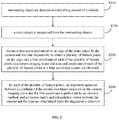
- FIG. 2is a flow chart of a sensor calibration method according to Embodiment 2 of the present disclosure.
- the embodimentis on the basis of embodiment 1, as shown in FIG. 2 , the method may include the following.
- surrounding objectsare detected in a travelling process of a vehicle.
- a static objectis recognized from the surrounding objects.
- feature extractionis performed on an edge of the static object by the camera and the lidar respectively to obtain a plurality of feature points on the edge, and a first coordinate of each of the plurality of feature points in a camera imaging plane and a second coordinate of each of the plurality of feature points in a lidar coordinate system are obtained.
- image data including the static objectmay be acquired by the camera, and the contour of the static object on the image may be recognized based on image recognition technology, and the first coordinate of each of the plurality of feature points in the camera imaging plane can be determined.
- the camera imaging planeis in an image coordinate system.
- the point cloud data of the surrounding environment of the vehiclemay be acquired simultaneously by the lidar, and 3D environment image may be obtained by 3D scene construction. Then, based on static object recognition, the contour of the static object on the 3D environment image can be determined, and the second coordinate of each of the plurality of feature points in the lidar coordinate system can be determined.
- the second coordinateis a 3D coordinate, and the second coordinate and the first coordinate correspond to the same feature point on the edge of the static object.
- the edgemay include one or more of a straight line and a circular ring.
- the edge of a tree on the road sideis a straight line
- the edge of the utility poleis also a straight line
- the edge of a tire of a vehicle on the road sideis a circular ring.
- the feature extraction of the straight linemay be affected by noise, and the calibration accuracy can be affected
- the feature extraction of the circular ringmay be more suitable, for the circular ring may have a circular equation, and feature extraction can be performed in combination with the circular equation, such that the influence of noise can be reduced, and the calibration accuracy can be improved.
- an alignment operation between a coordinate of the second coordinate projected on the camera imaging plane and the first coordinateis performed by an iterative method, and a rotation matrix and a translation vector between the camera and the lidar are determined when the alignment is achieved.
- the second coordinate in the lidar coordinate systemmay be projected onto the camera imaging plane to obtain a third coordinate, i.e., the 3D point cloud data is converted into 2D data.
- the alignment operation between the first coordinate and the third coordinatemay be performed on the camera imaging plane, when the first coordinate coincides with the third coordinate (i.e., coordinate alignment), the rotation matrix corresponding to the rotation operation in the coordinate alignment process can be determined, and the translation vector corresponding to the translation operation can also be determined, and the rotation matrix and the translation vector may be used as calibration parameters between the camera and the lidar.
- the coordinate of a feature pointin the process of coordinate alignment, may be fixed, and position coordinate of another feature point may be changed by iteration, until the coordinates of the two feature points are aligned.
- the first coordinatemay be fixed, and the position of the third coordinate may be sequentially changed, until it is aligned with the first coordinate.
- the coordinate transformation parameters involved in the third coordinatemay be used as the extrinsic parameter between the camera and the sensor.
- the rotation matrix and the translation vector determined in the coordinate alignment processmay be transformed and calculated, to obtain the coordinate transformation parameters between the feature points on the edge of the static object in the camera coordinate system and the laser point cloud coordinate system, as the final extrinsic parameter between the camera and the lidar.
- the surrounding objectsare detected, the static object is recognized from the surrounding objects, feature extraction is performed on the edge of the static object by the camera and the lidar respectively to obtain a plurality of feature points on the edge, and the automatic calibration between camera and lidar is realized by using coordinate transformation of the feature points in the image coordinate system and laser point cloud coordinate system respectively, the coordinate transformation between the image coordinate system and the laser point cloud coordinate system is performed by using multiple feature points on the edge to realize automatic calibration between the camera and the laser radar.
- the sensor calibration during travelling of the vehiclecan be achieved, and the convenience of sensor calibration can be improved.
- a simple graphicis selected as the contour edge in the edge recognition process of the static object, the accuracy of edge recognition and sensor calibration can be improved.
- FIG. 3is a schematic diagram of a sensor calibration device according to Embodiment 3 of the present disclosure.
- the embodimentmay be applicable to the case of calibrating a sensor, the device may be implemented by means of software and/or hardware, and may be configured on a computing device.
- the computing devicemay be configured on a vehicle, such as an unmanned vehicle with control and computing capabilities.
- the deviceincludes an object detecting module 310 , a static object recognizing module 320 , and a calibrating module 330 .
- the object detecting module 310is configured to detect surrounding objects in a travelling process of a vehicle.
- the static object recognizing module 320is configured to recognize a static object from the surrounding objects.
- the calibrating module 330is configured to perform feature extraction on the static object by a camera and a lidar respectively, and calibrate an extrinsic parameter of the camera and the lidar based on the extracted feature.
- the object detecting module 310includes an obstacle detecting unit, and a detection result verification unit.
- the obstacle detecting unitis configured to perform obstacle detection by the camera and the lidar respectively.
- the detection result verification unitis configured to perform verification on an obstacle detection result of the camera and an obstacle detection result of the lidar, to obtain a final obstacle detection result, and determine the surrounding objects based on the final obstacle detection result.
- the static object recognizing module 320is configured to recognize the static object from the surrounding objects based on a pre-trained recognition model.
- the calibrating moduleincludes a coordinate obtaining unit, and a coordinate alignment unit.
- the coordinate obtaining unitis configured to perform feature extraction on an edge of the static object by the camera and the lidar respectively to obtain a plurality of feature points on the edge, and obtain a first coordinate of each of the plurality of feature points in a camera imaging plane and a second coordinate of each of the plurality of feature points in a lidar coordinate system.
- the coordinate alignment unitis configured to, for each of the plurality of feature points, perform an alignment operation between a coordinate of the second coordinate projected on the camera imaging plane and the first coordinate by an iterative method, and determine a rotation matrix and a translation vector between the camera and the lidar when the alignment is achieved.
- the edgeincludes one or more of a straight line and a circular ring.
- the static objectincludes one or more of a car, a house, a tree, and a utility pole.
- the sensor calibration device provided by the embodiment of the present disclosurecan perform the sensor calibration method provided by any embodiment of the present disclosure, and can have the corresponding functional modules for executing the method, and can achieve corresponding beneficial effects.
- FIG. 4is a schematic diagram of a computer device according to Embodiment 4 of the present disclosure.
- FIG. 4illustrates a block diagram of a computer device 412 suitable for implementing embodiments of the present disclosure.
- the computer device 412 shown in FIG. 4is merely an example, and should not impose any limitation to the functions and scopes of embodiments of the present disclosure.
- the computer device 412may be embodied in the form of a general-purpose computing device.
- Components of the computer device 412may include, but are not limited to, one or more processors 416 , a storage device 428 , and a bus 418 that connects different components (including the storage device 428 and the processor 416 ).
- the bus 418represents one or more of any of several types of bus structures, including a memory bus or a memory controller, a peripheral bus, an accelerated graphics port, a processor, or a local bus using any of a variety of bus structures.
- these architecturesinclude, but are not limited to, an Industry Standard Architecture (hereinafter referred to as ISA) bus, a Micro Channel Architecture (hereinafter referred to as MAC) bus, an enhanced ISA bus, a Video Electronics Standards Association (hereinafter referred to as VESA) local bus and Peripheral Component Interconnection (PCI) bus.
- ISAIndustry Standard Architecture
- MACMicro Channel Architecture
- VESAVideo Electronics Standards Association
- PCIPeripheral Component Interconnection
- the computer device 412typically includes a variety of computer system readable media. These media may be any available media accessible by the computer device 412 , including volatile and non-volatile media, removable and non-removable media.
- the storage device 428may include a computer system readable medium in the form of volatile memory, such as a random-access memory (hereinafter referred to as RAM) 430 and/or a high-speed cache memory 432 .
- the computer device 412may further include other removable or non-removable, volatile or non-volatile computer system storage medium.
- the storage system 434may be configured to read and write non-removable and non-volatile magnetic media (not shown in FIG. 4 , commonly referred to as a “hard drive”).
- a magnetic disk driverfor reading from and writing to a removable and non-volatile magnetic disk (such as “floppy disk”) and a disk driver for reading from and writing to a removable and non-volatile optical disk (such as compact disk read only memory (hereinafter referred to as CD-ROM), a digital video disc read only memory (hereinafter referred to as DVD-ROM) or other optical media
- each drivermay be connected to the bus 418 via one or more data medium interfaces.
- the storage device 428may include at least one program product.
- the program producthas a set of (such as, at least one) program modules configured to perform the functions of various embodiments of the present disclosure.
- a program/utility 440 having a set of (at least one) the program modules 442may be stored in, for example, the storage device 428 .
- the program module 442may include, but is not limited to, an operating system, one or more application programs, other programs modules and program data. Each of these examples, or some combination thereof, may include an implementation of a network environment.
- the program module 442is generally configured to perform functions and/or methods in embodiments of the present disclosure.
- the computer device 412may also communicate with one or more external devices 414 (e.g., a keyboard, a pointing device, a camera, a display 424 ). Furthermore, the computer device 412 may also communicate with one or more devices enabling a user to interact with the computer device 412 and/or other devices (such as a network card, a modem, etc.) enabling the computer device 412 to communicate with one or more computer devices. This communication can be performed via the input/output (I/O) interface 422 .
- I/Oinput/output
- the computer device 412may communicate with one or more networks (such as a local area network (hereafter referred to as LAN), a wide area network (hereafter referred to as WAN) and/or a public network such as the Internet) through a network adapter 420 .
- the network adapter 420communicates with other modules of the computer device 412 over the bus 418 .
- other hardware and/or software modulesmay be used in conjunction with the computer device 412 , which include, but are not limited to, microcode, device drivers, redundant processing units, external disk drive arrays, RAID systems, tape drives, as well as data backup storage systems and the like.
- the processor 416is configured to execute various functional applications and data processing by running a program stored in the storage device 428 , for example, to implement the sensor calibration method provided by the above-described embodiments of the present disclosure.
- the methodincludes: detecting surrounding objects in a travelling process of a vehicle; recognizing a static object from the surrounding objects; performing feature extraction on the static object by a camera and a lidar, respectively; and calibrating an extrinsic parameter of the camera and the lidar based on the extracted feature.
- Embodiment 5 of the present disclosurefurther provides a computer storage medium having stored thereon a computer program that, when executed by a processor, causes the sensor calibration method according to any embodiment of the present disclosure to be implemented.
- the methodincludes: detecting surrounding objects in a travelling process of a vehicle; recognizing a static object from the surrounding objects; performing feature extraction on the static object by a camera and a lidar, respectively; and calibrating an extrinsic parameter of the camera and the lidar based on the extracted feature.
- the above non-transitory computer readable storage mediummay adopt any combination of one or more computer readable medium(s).
- the computer readable mediummay be a computer readable signal medium or a computer readable storage medium.
- the computer readable storage mediummay be, but is not limited to, for example, an electrical, magnetic, optical, electromagnetic, infrared, or semiconductor system, apparatus, device, component or any combination thereof.
- the computer readable storage mediumincludes: an electrical connection having one or more wires, a portable computer disk, a hard disk, a random access memory (RAM), a read only memory (ROM), an Erasable Programmable Read Only Memory (EPROM) or a flash memory, an optical fiber, a compact disc read-only memory (CD-ROM), an optical memory component, a magnetic memory component, or any suitable combination thereof.
- the computer readable storage mediummay be any tangible medium including or storing programs. The programs may be used by or in connection with an instruction executed system, apparatus or device.
- the computer readable signal mediummay include a data signal propagating in baseband or as part of carrier wave, which carries computer readable program codes. Such propagated data signal may take any of a variety of forms, including but not limited to an electromagnetic signal, an optical signal, or any suitable combination thereof.
- the computer readable signal mediummay also be any computer readable medium other than the computer readable storage medium, which may send, propagate, or transport programs used by or in connection with an instruction executed system, apparatus or device.
- the program code stored on the computer readable mediummay be transmitted using any appropriate medium, including but not limited to wireless, wireline, optical fiber cable, RF, or any suitable combination thereof.
- the computer program code for carrying out operations of embodiments of the present disclosuremay be written in one or more programming languages.
- the programming languageincludes an object-oriented programming language, such as Java, Smalltalk, C++, as well as conventional procedural programming language, such as “C” language or similar programming language.
- the program codemay be executed entirely on a user's computer, partly on the user's computer, as a separate software package, partly on the user's computer, partly on a remote computer, or entirely on the remote computer or server.
- the remote computermay be connected to the user's computer or an external computer (such as using an Internet service provider to connect over the Internet) through any kind of network, including a Local Area Network (hereafter referred as to LAN) or a Wide Area Network (hereafter referred as to WAN).
- LANLocal Area Network
- WANWide Area Network
- Embodiments of the present disclosurefurther provide a vehicle.
- the vehicleincludes a vehicle body, the computer device according to an embodiment of the present disclosure, and at least two sensors disposed on the vehicle body.
- the at least two sensorsinclude a lidar and a camera, and the at least two sensors respectively communicate with the computer device.
- the location of the sensor on the vehicle bodycan be set according to the design of the vehicle.
- the vehiclemay be an unmanned vehicle with control and computing capabilities.
- the sensormay send the data to the computer device, such that the computer device can perform data processing, such as perform calibration between the lidar and the camera.
Landscapes
- Engineering & Computer Science (AREA)
- Physics & Mathematics (AREA)
- Radar, Positioning & Navigation (AREA)
- Remote Sensing (AREA)
- General Physics & Mathematics (AREA)
- Computer Networks & Wireless Communication (AREA)
- Theoretical Computer Science (AREA)
- Computer Vision & Pattern Recognition (AREA)
- Electromagnetism (AREA)
- Data Mining & Analysis (AREA)
- Life Sciences & Earth Sciences (AREA)
- Artificial Intelligence (AREA)
- Bioinformatics & Cheminformatics (AREA)
- Bioinformatics & Computational Biology (AREA)
- Multimedia (AREA)
- Evolutionary Biology (AREA)
- Evolutionary Computation (AREA)
- General Engineering & Computer Science (AREA)
- Traffic Control Systems (AREA)
- Optical Radar Systems And Details Thereof (AREA)
- Studio Devices (AREA)
- Image Analysis (AREA)
Abstract
Description
Claims (15)
Applications Claiming Priority (2)
| Application Number | Priority Date | Filing Date | Title |
|---|---|---|---|
| CN201811094353.7 | 2018-09-19 | ||
| CN201811094353.7ACN109343061B (en) | 2018-09-19 | 2018-09-19 | Sensor calibration method and device, computer equipment, medium and vehicle |
Publications (2)
| Publication Number | Publication Date |
|---|---|
| US20200089971A1 US20200089971A1 (en) | 2020-03-19 |
| US11042762B2true US11042762B2 (en) | 2021-06-22 |
Family
ID=65305532
Family Applications (1)
| Application Number | Title | Priority Date | Filing Date |
|---|---|---|---|
| US16/574,995Active2039-10-04US11042762B2 (en) | 2018-09-19 | 2019-09-18 | Sensor calibration method and device, computer device, medium, and vehicle |
Country Status (4)
| Country | Link |
|---|---|
| US (1) | US11042762B2 (en) |
| EP (1) | EP3627180B1 (en) |
| JP (1) | JP6915009B2 (en) |
| CN (1) | CN109343061B (en) |
Cited By (4)
| Publication number | Priority date | Publication date | Assignee | Title |
|---|---|---|---|---|
| US20210318149A1 (en)* | 2020-04-14 | 2021-10-14 | Plusai Limited | System and method for simultaneously multiple sensor calibration and transformation matrix computation |
| US11609340B2 (en) | 2020-04-14 | 2023-03-21 | Plusai, Inc. | System and method for GPS based automatic initiation of sensor calibration |
| US11673567B2 (en) | 2020-04-14 | 2023-06-13 | Plusai, Inc. | Integrated fiducial marker for simultaneously calibrating sensors of different types |
| US20230260255A1 (en)* | 2020-04-09 | 2023-08-17 | Sun Yat-Sen University | Three-dimensional object detection framework based on multi-source data knowledge transfer |
Families Citing this family (40)
| Publication number | Priority date | Publication date | Assignee | Title |
|---|---|---|---|---|
| CN109901141B (en)* | 2019-02-28 | 2021-03-30 | 东软睿驰汽车技术(沈阳)有限公司 | Calibration method and device |
| US11482008B2 (en)* | 2019-07-05 | 2022-10-25 | Nvidia Corporation | Directing board repositioning during sensor calibration for autonomous vehicles |
| CN110488234B (en)* | 2019-08-30 | 2021-09-10 | 北京百度网讯科技有限公司 | External parameter calibration method, device, equipment and medium for vehicle-mounted millimeter wave radar |
| CN110766758B (en)* | 2019-09-12 | 2022-08-09 | 浙江大华技术股份有限公司 | Calibration method, device, system and storage device |
| US11352010B2 (en)* | 2019-09-30 | 2022-06-07 | Baidu Usa Llc | Obstacle perception calibration system for autonomous driving vehicles |
| CN112816949B (en)* | 2019-11-18 | 2024-04-16 | 商汤集团有限公司 | Sensor calibration method and device, storage medium, and calibration system |
| US11494939B2 (en) | 2019-12-02 | 2022-11-08 | Toyota Research Institute, Inc. | Sensor self-calibration in the wild by coupling object detection and analysis-by-synthesis |
| CN111025250B (en)* | 2020-01-07 | 2022-05-13 | 湖南大学 | On-line calibration method for vehicle-mounted millimeter wave radar |
| US11360197B2 (en)* | 2020-01-07 | 2022-06-14 | Luminar, Llc | Calibration of sensor systems |
| CN113376617B (en)* | 2020-02-25 | 2024-04-05 | 北京京东乾石科技有限公司 | Method, device, storage medium and system for evaluating accuracy of radar calibration result |
| CN113538587A (en)* | 2020-04-16 | 2021-10-22 | 深圳先进技术研究院 | A camera coordinate transformation method, terminal and storage medium |
| CN111627072B (en)* | 2020-04-30 | 2023-10-24 | 贝壳技术有限公司 | Method, device and storage medium for calibrating multiple sensors |
| CN111612760B (en)* | 2020-05-20 | 2023-11-17 | 阿波罗智联(北京)科技有限公司 | Method and device for detecting obstacles |
| JP7402121B2 (en)* | 2020-06-02 | 2023-12-20 | 株式会社日立製作所 | Object detection system and object detection method |
| TWI755765B (en)* | 2020-06-22 | 2022-02-21 | 中強光電股份有限公司 | System for calibrating visual coordinate system and depth coordinate system, calibration method and calibration device |
| CN111857174A (en)* | 2020-06-23 | 2020-10-30 | 国网江苏省电力有限公司徐州供电分公司 | A UAV power data calibration method based on lidar data |
| CN113847930A (en) | 2020-06-28 | 2021-12-28 | 图森有限公司 | Multi-sensor calibration system |
| AU2021204030A1 (en) | 2020-06-28 | 2022-01-20 | Beijing Tusen Weilai Technology Co., Ltd. | Multi-sensor calibration system |
| JP6837626B1 (en)* | 2020-08-03 | 2021-03-03 | 株式会社空間技術総合研究所 | Feature data generation system, feature database update system, and feature data generation method |
| CN114063046B (en)* | 2020-08-05 | 2025-05-13 | 北京万集科技股份有限公司 | Parameter calibration method, device, computer equipment and storage medium |
| CN112255621B (en)* | 2020-10-09 | 2022-08-30 | 中国第一汽车股份有限公司 | Calibration method and device of vehicle sensor, electronic equipment and storage medium |
| CN113759346B (en)* | 2020-10-10 | 2024-06-18 | 北京京东乾石科技有限公司 | Laser radar calibration method and device, electronic equipment and storage medium |
| US11960276B2 (en)* | 2020-11-19 | 2024-04-16 | Tusimple, Inc. | Multi-sensor collaborative calibration system |
| TWI768548B (en)* | 2020-11-19 | 2022-06-21 | 財團法人資訊工業策進會 | System and method for generating basic information for positioning and self-positioning determination device |
| JP7508350B2 (en)* | 2020-12-04 | 2024-07-01 | 株式会社日立製作所 | CALIBRATION APPARATUS AND CALIBRATION METHOD |
| CN112712032A (en)* | 2020-12-30 | 2021-04-27 | 南昌觅真科技有限公司 | Semi-automatic object posture labeling scheme |
| CN112835019B (en)* | 2020-12-30 | 2024-07-05 | 广州小鹏自动驾驶科技有限公司 | Vehicle sensor calibration method and device, vehicle and storage medium |
| KR102498435B1 (en)* | 2021-01-28 | 2023-02-13 | 경북대학교 산학협력단 | Apparatus and method for calibration of sensor system of autonomous vehicle |
| CN113391299B (en)* | 2021-04-30 | 2023-09-22 | 深圳市安思疆科技有限公司 | Parameter calibration method and device for scanning area array laser radar |
| CN112986982B (en)* | 2021-05-12 | 2021-07-30 | 长沙万为机器人有限公司 | Environment map reference positioning method and device and mobile robot |
| EP4343370A4 (en)* | 2021-06-15 | 2024-06-19 | Huawei Technologies Co., Ltd. | CALIBRATION METHOD AND DEVICE FOR AUTOMATICALLY DRIVING VEHICLE |
| CN113340334B (en)* | 2021-07-29 | 2021-11-30 | 新石器慧通(北京)科技有限公司 | Sensor calibration method and device for unmanned vehicle and electronic equipment |
| CN113838141B (en)* | 2021-09-02 | 2023-07-25 | 中南大学 | A method and system for external parameter calibration of a single-line laser radar and a visible light camera |
| CN113734197A (en)* | 2021-09-03 | 2021-12-03 | 合肥学院 | Unmanned intelligent control scheme based on data fusion |
| CN114170324A (en)* | 2021-12-09 | 2022-03-11 | 深圳市商汤科技有限公司 | Calibration method and device, electronic equipment and storage medium |
| EP4198920A1 (en)* | 2021-12-15 | 2023-06-21 | Volvo Autonomous Solutions AB | A method and unit for evaluating a performance of an obstacle detection system |
| CN114862964B (en)* | 2022-04-27 | 2025-09-16 | 武汉智行者科技有限公司 | Automatic calibration method for sensor, electronic equipment and storage medium |
| GB202212757D0 (en)* | 2022-09-01 | 2022-10-19 | Reincubate Ltd | Devices, systems and methods for image adjustment |
| AU2024249353A1 (en)* | 2023-03-24 | 2025-10-02 | i-PRO Co., Ltd. | Monitoring device and monitoring system |
| CN117437303B (en)* | 2023-12-18 | 2024-02-23 | 江苏尚诚能源科技有限公司 | Method and system for calibrating camera external parameters |
Citations (19)
| Publication number | Priority date | Publication date | Assignee | Title |
|---|---|---|---|---|
| US20110032570A1 (en)* | 2009-08-07 | 2011-02-10 | Daisaku Imaizumi | Captured image processing system and recording medium |
| CN103559791A (en) | 2013-10-31 | 2014-02-05 | 北京联合大学 | Vehicle detection method fusing radar and CCD camera signals |
| CN103837869A (en) | 2014-02-26 | 2014-06-04 | 北京工业大学 | Vector-relation-based method for calibrating single-line laser radar and CCD camera |
| US20140241629A1 (en)* | 2013-02-28 | 2014-08-28 | Facebook, Inc. | Methods and systems for differentiating synthetic and non-synthetic images |
| CN105678689A (en) | 2015-12-31 | 2016-06-15 | 百度在线网络技术(北京)有限公司 | High-precision map data registration relationship determination method and device |
| US20160249039A1 (en) | 2015-02-24 | 2016-08-25 | HypeVR | Lidar stereo fusion live action 3d model video reconstruction for six degrees of freedom 360° volumetric virtual reality video |
| US20170041587A1 (en)* | 2015-04-29 | 2017-02-09 | Northrop Grumman Systems Corporation | Dynamically adjustable situational awareness interface for control of unmanned vehicles |
| WO2017057042A1 (en) | 2015-09-30 | 2017-04-06 | ソニー株式会社 | Signal processing device, signal processing method, program, and object detection system |
| US20170124781A1 (en)* | 2015-11-04 | 2017-05-04 | Zoox, Inc. | Calibration for autonomous vehicle operation |
| US20180082421A1 (en)* | 2016-09-22 | 2018-03-22 | Sony Corporation | Image processing system and method to reconstruct a three-dimensional (3d) anatomical surface |
| CN108020826A (en) | 2017-10-26 | 2018-05-11 | 厦门大学 | Multi-line laser radar and multichannel camera mixed calibration method |
| DE102016225595A1 (en) | 2016-12-20 | 2018-06-21 | Siemens Aktiengesellschaft | Method and arrangement for calibrating at least one sensor of a rail vehicle |
| CN108198223A (en) | 2018-01-29 | 2018-06-22 | 清华大学 | A kind of laser point cloud and the quick method for precisely marking of visual pattern mapping relations |
| CN108399643A (en) | 2018-03-15 | 2018-08-14 | 南京大学 | A kind of outer ginseng calibration system between laser radar and camera and method |
| CN108519605A (en) | 2018-04-09 | 2018-09-11 | 重庆邮电大学 | Road edge detection method based on lidar and camera |
| US20190063945A1 (en)* | 2017-08-22 | 2019-02-28 | TuSimple | Verification module system and method for motion-based lane detection with multiple sensors |
| US20190120934A1 (en)* | 2017-10-19 | 2019-04-25 | GM Global Technology Operations LLC | Three-dimensional alignment of radar and camera sensors |
| US20190204427A1 (en)* | 2017-12-28 | 2019-07-04 | Lyft, Inc. | Sensor calibration facility |
| US10726579B1 (en)* | 2019-11-13 | 2020-07-28 | Honda Motor Co., Ltd. | LiDAR-camera calibration |
Family Cites Families (2)
| Publication number | Priority date | Publication date | Assignee | Title |
|---|---|---|---|---|
| CN106558080B (en)* | 2016-11-14 | 2020-04-24 | 天津津航技术物理研究所 | Monocular camera external parameter online calibration method |
| CN107576960B (en)* | 2017-09-04 | 2021-03-16 | 赵建辉 | Target detection method and system for visual radar space-time information fusion |
- 2018
- 2018-09-19CNCN201811094353.7Apatent/CN109343061B/enactiveActive
- 2019
- 2019-09-06EPEP19195851.1Apatent/EP3627180B1/enactiveActive
- 2019-09-18USUS16/574,995patent/US11042762B2/enactiveActive
- 2019-09-18JPJP2019169174Apatent/JP6915009B2/ennot_activeExpired - Fee Related
Patent Citations (20)
| Publication number | Priority date | Publication date | Assignee | Title |
|---|---|---|---|---|
| US20110032570A1 (en)* | 2009-08-07 | 2011-02-10 | Daisaku Imaizumi | Captured image processing system and recording medium |
| US20140241629A1 (en)* | 2013-02-28 | 2014-08-28 | Facebook, Inc. | Methods and systems for differentiating synthetic and non-synthetic images |
| CN103559791A (en) | 2013-10-31 | 2014-02-05 | 北京联合大学 | Vehicle detection method fusing radar and CCD camera signals |
| CN103837869A (en) | 2014-02-26 | 2014-06-04 | 北京工业大学 | Vector-relation-based method for calibrating single-line laser radar and CCD camera |
| CN103837869B (en) | 2014-02-26 | 2016-06-01 | 北京工业大学 | Based on single line laser radar and the CCD camera scaling method of vector relations |
| US20160249039A1 (en) | 2015-02-24 | 2016-08-25 | HypeVR | Lidar stereo fusion live action 3d model video reconstruction for six degrees of freedom 360° volumetric virtual reality video |
| US20170041587A1 (en)* | 2015-04-29 | 2017-02-09 | Northrop Grumman Systems Corporation | Dynamically adjustable situational awareness interface for control of unmanned vehicles |
| WO2017057042A1 (en) | 2015-09-30 | 2017-04-06 | ソニー株式会社 | Signal processing device, signal processing method, program, and object detection system |
| US20170124781A1 (en)* | 2015-11-04 | 2017-05-04 | Zoox, Inc. | Calibration for autonomous vehicle operation |
| CN105678689A (en) | 2015-12-31 | 2016-06-15 | 百度在线网络技术(北京)有限公司 | High-precision map data registration relationship determination method and device |
| US20180082421A1 (en)* | 2016-09-22 | 2018-03-22 | Sony Corporation | Image processing system and method to reconstruct a three-dimensional (3d) anatomical surface |
| DE102016225595A1 (en) | 2016-12-20 | 2018-06-21 | Siemens Aktiengesellschaft | Method and arrangement for calibrating at least one sensor of a rail vehicle |
| US20190063945A1 (en)* | 2017-08-22 | 2019-02-28 | TuSimple | Verification module system and method for motion-based lane detection with multiple sensors |
| US20190120934A1 (en)* | 2017-10-19 | 2019-04-25 | GM Global Technology Operations LLC | Three-dimensional alignment of radar and camera sensors |
| CN108020826A (en) | 2017-10-26 | 2018-05-11 | 厦门大学 | Multi-line laser radar and multichannel camera mixed calibration method |
| US20190204427A1 (en)* | 2017-12-28 | 2019-07-04 | Lyft, Inc. | Sensor calibration facility |
| CN108198223A (en) | 2018-01-29 | 2018-06-22 | 清华大学 | A kind of laser point cloud and the quick method for precisely marking of visual pattern mapping relations |
| CN108399643A (en) | 2018-03-15 | 2018-08-14 | 南京大学 | A kind of outer ginseng calibration system between laser radar and camera and method |
| CN108519605A (en) | 2018-04-09 | 2018-09-11 | 重庆邮电大学 | Road edge detection method based on lidar and camera |
| US10726579B1 (en)* | 2019-11-13 | 2020-07-28 | Honda Motor Co., Ltd. | LiDAR-camera calibration |
Non-Patent Citations (9)
| Title |
|---|
| Chinese Patent Application No. 201811094353.7 English translation of Office Action dated Mar. 16, 2020, 8 pages. |
| Chinese Patent Application No. 201811094353.7 English translation of Second Office Action dated Oct. 22, 2020, 4 pages. |
| Chinese Patent Application No. 201811094353.7 Office Action dated Mar. 16, 2020, 8 pages. |
| Chinese Patent Application No. 201811094353.7 Second Office Action dated Oct. 22, 2020, 5 pages. |
| European Patent Application No. 19195851.1 extended Search and Opinion dated Feb. 13, 2020, 7 pages. |
| Japanese Patent Application No. 2019-169174 English translation of Office Action dated Sep. 29, 2020, 4 pages. |
| Japanese Patent Application No. 2019-169174 Office Action dated Sep. 29, 2020, 4 pages. |
| Tang, X., "Research on Road and Obstacle Detection Method Based on Information Fusion", China Master's thesis Full-text Database Information Technology Series, Abstract, Jul. 2012, 4 pages. |
| Zhang, S. "Research on obstacle detection technology based on radar and camera of driverless smart vehicles" Dissertation, Chang'an University, Xi'an, China, 2013, 65 pages. |
Cited By (6)
| Publication number | Priority date | Publication date | Assignee | Title |
|---|---|---|---|---|
| US20230260255A1 (en)* | 2020-04-09 | 2023-08-17 | Sun Yat-Sen University | Three-dimensional object detection framework based on multi-source data knowledge transfer |
| US20210318149A1 (en)* | 2020-04-14 | 2021-10-14 | Plusai Limited | System and method for simultaneously multiple sensor calibration and transformation matrix computation |
| US11609340B2 (en) | 2020-04-14 | 2023-03-21 | Plusai, Inc. | System and method for GPS based automatic initiation of sensor calibration |
| US11635313B2 (en)* | 2020-04-14 | 2023-04-25 | Plusai, Inc. | System and method for simultaneously multiple sensor calibration and transformation matrix computation |
| US11673567B2 (en) | 2020-04-14 | 2023-06-13 | Plusai, Inc. | Integrated fiducial marker for simultaneously calibrating sensors of different types |
| US12221123B2 (en) | 2020-04-14 | 2025-02-11 | Plusai, Inc. | Integrated fiducial marker for simultaneously calibrating sensors of different types |
Also Published As
| Publication number | Publication date |
|---|---|
| CN109343061A (en) | 2019-02-15 |
| US20200089971A1 (en) | 2020-03-19 |
| EP3627180A1 (en) | 2020-03-25 |
| EP3627180B1 (en) | 2022-12-28 |
| JP2020047276A (en) | 2020-03-26 |
| CN109343061B (en) | 2021-04-02 |
| JP6915009B2 (en) | 2021-08-04 |
Similar Documents
| Publication | Publication Date | Title |
|---|---|---|
| US11042762B2 (en) | Sensor calibration method and device, computer device, medium, and vehicle | |
| US11379699B2 (en) | Object detection method and apparatus for object detection | |
| US20200088858A1 (en) | Multi-sensor calibration method, multi-sensor calibration device, computer device, medium and vehicle | |
| CN112861653B (en) | Method, system, equipment and storage medium for detecting fused image and point cloud information | |
| US11227395B2 (en) | Method and apparatus for determining motion vector field, device, storage medium and vehicle | |
| CN109270545B (en) | Positioning true value verification method, device, equipment and storage medium | |
| CN109116374B (en) | Method, device and equipment for determining distance of obstacle and storage medium | |
| US11017244B2 (en) | Obstacle type recognizing method and apparatus, device and storage medium | |
| US11087474B2 (en) | Method, apparatus, device, and storage medium for calibrating posture of moving obstacle | |
| US20240029303A1 (en) | Three-dimensional target detection method and apparatus | |
| CN108734058B (en) | Obstacle type identification method, device, equipment and storage medium | |
| US12125287B2 (en) | Detecting obstacle | |
| JP2018530825A (en) | System and method for non-obstacle area detection | |
| CN110853085B (en) | Semantic SLAM-based mapping method and device and electronic equipment | |
| CN114419564B (en) | Vehicle pose detection method, device, equipment, medium and automatic driving vehicle | |
| CN114664102A (en) | Navigation system with parking space recognition mechanism and operation method thereof | |
| US12154349B2 (en) | Method for detecting three-dimensional objects in roadway and electronic device | |
| CN113469045A (en) | Unmanned card-collecting visual positioning method and system, electronic equipment and storage medium | |
| US11842440B2 (en) | Landmark location reconstruction in autonomous machine applications | |
| US12283120B2 (en) | Method for detecting three-dimensional objects in relation to autonomous driving and electronic device | |
| US20250218117A1 (en) | Method, Apparatus, Device, Vehicle, and Media for Creating a 3D Point Cloud Map | |
| CN116844134A (en) | Target detection methods, devices, electronic equipment, storage media and vehicles | |
| CN119644293A (en) | Target identification method, target identification device, electronic equipment, storage medium and vehicle |
Legal Events
| Date | Code | Title | Description |
|---|---|---|---|
| AS | Assignment | Owner name:BAIDU ONLINE NETWORK TECHNOLOGY (BEIJING) CO., LTD., CHINA Free format text:ASSIGNMENT OF ASSIGNORS INTEREST;ASSIGNORS:LI, SHIRUI;XIE, YUANFAN;ZHOU, XUN;AND OTHERS;REEL/FRAME:050419/0721 Effective date:20190806 | |
| FEPP | Fee payment procedure | Free format text:ENTITY STATUS SET TO UNDISCOUNTED (ORIGINAL EVENT CODE: BIG.); ENTITY STATUS OF PATENT OWNER: LARGE ENTITY | |
| AS | Assignment | Owner name:BAIDU ONLINE NETWORK TECHNOLOGY (BEIJING) CO., LTD., CHINA Free format text:CORRECTIVE ASSIGNMENT TO CORRECT THE APPLICANT STREET ADDRESS PREVIOUSLY RECORDED AT REEL: 050419 FRAME: 0721. ASSIGNOR(S) HEREBY CONFIRMS THE ASSIGNMENT;ASSIGNORS:LI, SHIRUI;XIE, YUANFAN;ZHOU, XUN;AND OTHERS;REEL/FRAME:050835/0547 Effective date:20190806 | |
| STPP | Information on status: patent application and granting procedure in general | Free format text:NON FINAL ACTION MAILED | |
| STPP | Information on status: patent application and granting procedure in general | Free format text:RESPONSE TO NON-FINAL OFFICE ACTION ENTERED AND FORWARDED TO EXAMINER | |
| STPP | Information on status: patent application and granting procedure in general | Free format text:NOTICE OF ALLOWANCE MAILED -- APPLICATION RECEIVED IN OFFICE OF PUBLICATIONS | |
| STPP | Information on status: patent application and granting procedure in general | Free format text:PUBLICATIONS -- ISSUE FEE PAYMENT RECEIVED | |
| STPP | Information on status: patent application and granting procedure in general | Free format text:PUBLICATIONS -- ISSUE FEE PAYMENT VERIFIED | |
| STCF | Information on status: patent grant | Free format text:PATENTED CASE | |
| AS | Assignment | Owner name:APOLLO INTELLIGENT DRIVING (BEIJING) TECHNOLOGY CO., LTD., CHINA Free format text:ASSIGNMENT OF ASSIGNORS INTEREST;ASSIGNOR:BAIDU ONLINE NETWORK TECHNOLOGY (BEIJING) CO., LTD.;REEL/FRAME:057933/0812 Effective date:20210923 | |
| AS | Assignment | Owner name:APOLLO INTELLIGENT DRIVING TECHNOLOGY (BEIJING) CO., LTD., CHINA Free format text:CORRECTIVE ASSIGNMENT TO CORRECT THE APPLICANT NAME PREVIOUSLY RECORDED AT REEL: 057933 FRAME: 0812. ASSIGNOR(S) HEREBY CONFIRMS THE ASSIGNMENT;ASSIGNOR:BAIDU ONLINE NETWORK TECHNOLOGY (BEIJING) CO., LTD.;REEL/FRAME:058594/0836 Effective date:20210923 | |
| MAFP | Maintenance fee payment | Free format text:PAYMENT OF MAINTENANCE FEE, 4TH YEAR, LARGE ENTITY (ORIGINAL EVENT CODE: M1551); ENTITY STATUS OF PATENT OWNER: LARGE ENTITY Year of fee payment:4 |