US11042002B2 - Cable termination assembly - Google Patents
Cable termination assemblyDownload PDFInfo
- Publication number
- US11042002B2 US11042002B2US16/849,527US202016849527AUS11042002B2US 11042002 B2US11042002 B2US 11042002B2US 202016849527 AUS202016849527 AUS 202016849527AUS 11042002 B2US11042002 B2US 11042002B2
- Authority
- US
- United States
- Prior art keywords
- housing
- coupling element
- output
- output coupling
- assembly
- Prior art date
- Legal status (The legal status is an assumption and is not a legal conclusion. Google has not performed a legal analysis and makes no representation as to the accuracy of the status listed.)
- Expired - Fee Related
Links
Images


Classifications
- G—PHYSICS
- G02—OPTICS
- G02B—OPTICAL ELEMENTS, SYSTEMS OR APPARATUS
- G02B6/00—Light guides; Structural details of arrangements comprising light guides and other optical elements, e.g. couplings
- G02B6/24—Coupling light guides
- G02B6/36—Mechanical coupling means
- G—PHYSICS
- G02—OPTICS
- G02B—OPTICAL ELEMENTS, SYSTEMS OR APPARATUS
- G02B6/00—Light guides; Structural details of arrangements comprising light guides and other optical elements, e.g. couplings
- G02B6/44—Mechanical structures for providing tensile strength and external protection for fibres, e.g. optical transmission cables
- G02B6/4439—Auxiliary devices
- G02B6/444—Systems or boxes with surplus lengths
- G02B6/4441—Boxes
- G02B6/4442—Cap coupling boxes
- G02B6/4444—Seals
- G—PHYSICS
- G02—OPTICS
- G02B—OPTICAL ELEMENTS, SYSTEMS OR APPARATUS
- G02B6/00—Light guides; Structural details of arrangements comprising light guides and other optical elements, e.g. couplings
- G02B6/44—Mechanical structures for providing tensile strength and external protection for fibres, e.g. optical transmission cables
- G02B6/4439—Auxiliary devices
- G02B6/4471—Terminating devices ; Cable clamps
- G02B6/4472—Manifolds
- G—PHYSICS
- G02—OPTICS
- G02B—OPTICAL ELEMENTS, SYSTEMS OR APPARATUS
- G02B6/00—Light guides; Structural details of arrangements comprising light guides and other optical elements, e.g. couplings
- G02B6/44—Mechanical structures for providing tensile strength and external protection for fibres, e.g. optical transmission cables
- G02B6/4439—Auxiliary devices
- G02B6/4471—Terminating devices ; Cable clamps
- G02B6/44775—Cable seals e.g. feed-through
- G—PHYSICS
- G02—OPTICS
- G02B—OPTICAL ELEMENTS, SYSTEMS OR APPARATUS
- G02B6/00—Light guides; Structural details of arrangements comprising light guides and other optical elements, e.g. couplings
- G02B6/10—Light guides; Structural details of arrangements comprising light guides and other optical elements, e.g. couplings of the optical waveguide type
- G02B6/12—Light guides; Structural details of arrangements comprising light guides and other optical elements, e.g. couplings of the optical waveguide type of the integrated circuit kind
- G02B2006/12133—Functions
- G02B2006/1215—Splitter
- G—PHYSICS
- G02—OPTICS
- G02B—OPTICAL ELEMENTS, SYSTEMS OR APPARATUS
- G02B6/00—Light guides; Structural details of arrangements comprising light guides and other optical elements, e.g. couplings
- G02B6/24—Coupling light guides
- G02B6/26—Optical coupling means
- G02B6/28—Optical coupling means having data bus means, i.e. plural waveguides interconnected and providing an inherently bidirectional system by mixing and splitting signals
- G02B6/2804—Optical coupling means having data bus means, i.e. plural waveguides interconnected and providing an inherently bidirectional system by mixing and splitting signals forming multipart couplers without wavelength selective elements, e.g. "T" couplers, star couplers
- G02B6/2821—Optical coupling means having data bus means, i.e. plural waveguides interconnected and providing an inherently bidirectional system by mixing and splitting signals forming multipart couplers without wavelength selective elements, e.g. "T" couplers, star couplers using lateral coupling between contiguous fibres to split or combine optical signals
- G02B6/2835—Optical coupling means having data bus means, i.e. plural waveguides interconnected and providing an inherently bidirectional system by mixing and splitting signals forming multipart couplers without wavelength selective elements, e.g. "T" couplers, star couplers using lateral coupling between contiguous fibres to split or combine optical signals formed or shaped by thermal treatment, e.g. couplers
- G—PHYSICS
- G02—OPTICS
- G02B—OPTICAL ELEMENTS, SYSTEMS OR APPARATUS
- G02B6/00—Light guides; Structural details of arrangements comprising light guides and other optical elements, e.g. couplings
- G02B6/24—Coupling light guides
- G02B6/26—Optical coupling means
- G02B6/28—Optical coupling means having data bus means, i.e. plural waveguides interconnected and providing an inherently bidirectional system by mixing and splitting signals
- G02B6/293—Optical coupling means having data bus means, i.e. plural waveguides interconnected and providing an inherently bidirectional system by mixing and splitting signals with wavelength selective means
- G02B6/29379—Optical coupling means having data bus means, i.e. plural waveguides interconnected and providing an inherently bidirectional system by mixing and splitting signals with wavelength selective means characterised by the function or use of the complete device
- G02B6/2938—Optical coupling means having data bus means, i.e. plural waveguides interconnected and providing an inherently bidirectional system by mixing and splitting signals with wavelength selective means characterised by the function or use of the complete device for multiplexing or demultiplexing, i.e. combining or separating wavelengths, e.g. 1xN, NxM
- G—PHYSICS
- G02—OPTICS
- G02B—OPTICAL ELEMENTS, SYSTEMS OR APPARATUS
- G02B6/00—Light guides; Structural details of arrangements comprising light guides and other optical elements, e.g. couplings
- G02B6/24—Coupling light guides
- G02B6/36—Mechanical coupling means
- G02B6/38—Mechanical coupling means having fibre to fibre mating means
- G02B6/3807—Dismountable connectors, i.e. comprising plugs
- G02B6/3897—Connectors fixed to housings, casing, frames or circuit boards
- G—PHYSICS
- G02—OPTICS
- G02B—OPTICAL ELEMENTS, SYSTEMS OR APPARATUS
- G02B6/00—Light guides; Structural details of arrangements comprising light guides and other optical elements, e.g. couplings
- G02B6/44—Mechanical structures for providing tensile strength and external protection for fibres, e.g. optical transmission cables
- G02B6/4439—Auxiliary devices
- G02B6/444—Systems or boxes with surplus lengths
- G02B6/4441—Boxes
- G02B6/4448—Electro-optic
- G—PHYSICS
- G02—OPTICS
- G02B—OPTICAL ELEMENTS, SYSTEMS OR APPARATUS
- G02B6/00—Light guides; Structural details of arrangements comprising light guides and other optical elements, e.g. couplings
- G02B6/44—Mechanical structures for providing tensile strength and external protection for fibres, e.g. optical transmission cables
- G02B6/4439—Auxiliary devices
- G02B6/444—Systems or boxes with surplus lengths
- G02B6/44528—Patch-cords; Connector arrangements in the system or in the box
Definitions
- the present disclosurerelates generally to optical systems and assemblies and, in particular, to the storage and environmental protection of such devices.
- OSP enclosurescontain and provide protection for antenna units, kiosk terminals, and associated electronics equipment and wiring from harsh environmental factors such as sunlight, heat, wind, and rain.
- OSP enclosuresfurther provide desired fiber optic distribution functionality by containing therein a plurality of optical fibers, splitters, multiplexers, patch panels, and the like interconnected with one another in a desired manner, adding complexity to the enclosures with limited available space and thus adding assembly costs. Further, the complexity and limited space in hybrid arrangements make maintenance and repairs on the OSPs more cumbersome.
- Hybrid arrangement OSPsalso may be replaced prematurely when only a portion of such OSPs requires replacement, adding unnecessary costs.
- an optical fiber cable and termination unit assemblymay include a housing, a patch panel terminal, an optical signal assembly, an input optical fiber, and a plurality of output optical fibers.
- the housingmay have an interior surface.
- the patch panel terminalmay be coupled to the interior surface of the housing.
- the input optical fibermay extend into the housing to the optical signal assembly.
- the plurality of output optical fibersmay extend out of the housing from the patch panel terminal. In this manner, the optical signal assembly may divide a light beam emitted from the optical signal assembly into a plurality of light beams that are received by the patch panel terminal.
- the assemblymay include an output coupling element that may extend from the housing and may define a first longitudinal axis extending in directions towards and away from the housing.
- the plurality of output optical fibersmay extend through the output coupling element.
- the output coupling elementmay be substantially uniform in shape and size along a length of the output coupling element along the first longitudinal axis.
- the output coupling elementmay be tapered along a length of the output coupling element along the first longitudinal axis.
- the housingmay define a first hole through which the plurality of output optical fibers may extend.
- the output coupling elementmay contact the housing around an entire perimeter of the first hole to form a watertight seal at an interface of the output coupling element and the housing.
- the output coupling elementmay include a first flange, which may be an output coupling flange, extending from an end of the output coupling element in a direction transverse to the first longitudinal axis, and wherein an entire perimeter of the first flange is adhered to the interior surface of the housing to form the watertight seal.
- the output coupling elementmay be molded onto the housing around an entire perimeter of the first hole such that the output coupling element is inseparable from the housing without fracture of either one or both of the output coupling element and the housing.
- the plurality of output optical fibersmay extend through an outer sheath.
- the outer sheathmay extend through the output coupling element.
- the output coupling elementmay include a neck that may be at a location spaced from the housing and that may have a smaller inner perimeter than other sections of the output coupling element. In this manner, the neck may conform to a perimeter of the outer sheath to form the watertight seal.
- the output coupling elementmay abut an exterior surface of the housing opposite the interior surface of the housing. In this manner, the output coupling element may be completely exterior to the housing, and the abutment of the output coupling element may form the watertight seal.
- the output coupling elementmay extend into the first hole defined by the housing.
- the output coupling elementmay define an output coupling groove, or simply “output groove,” around an entire perimeter of the output coupling element.
- the housingmay extend into the output coupling groove at the first hole in an interference fit to form the watertight seal.
- a wall of the housingmay have a housing wall thickness and may extend around the entire perimeter of the output coupling element.
- a width of the output coupling groove in a direction a longitudinal axis of the output coupling element extendsmay be less than or equal to the housing wall thickness.
- the output coupling elementmay be made of rubber or plastic.
- the plurality of output optical fibersmay extend through an outer sheath.
- the outer sheathmay extend through the output coupling element.
- the output coupling elementmay include an outer boot, an inner boot, an inner lock, and an outer lock ring.
- the outer bootmay be in abutment against an exterior surface opposite the interior surface of the housing.
- the inner bootmay be adjacent to the interior surface of the housing.
- the outer lock ringmay be attached to the housing and may form a threaded connection with the inner lock ring. In this manner, upon threading the inner lock ring in a direction towards the housing, the inner boot may be compressed by the inner lock ring against the outer sheath of the output coupling element to form the watertight seal.
- the optical fiber cable and termination unit assemblymay include an input coupling element that may extend from the housing and may define a second longitudinal axis extending in directions towards and away from the housing.
- the input optical fibermay extend through the input coupling element.
- the housingmay define a second hole through which the input optical fiber cable may extend.
- the input coupling elementmay contact the housing around an entire perimeter of the second hole to form a watertight seal.
- the input coupling elementmay include a second flange, which may be an input coupling flange, extending from an end of the input coupling element in a direction transverse to the second longitudinal axis.
- a second flangewhich may be an input coupling flange, extending from an end of the input coupling element in a direction transverse to the second longitudinal axis.
- an entire perimeter of the second flangemay be adhered to the interior surface of the housing to form the watertight seal.
- the input coupling elementmay be molded onto the housing around the entire perimeter of the second hole such that the input coupling element may be inseparable from the housing without fracture of either one or both of the input coupling element and the housing.
- the input coupling elementmay extend into the second hole defined by the housing.
- the input coupling elementmay define an input coupling groove, or simply “input groove,” around an entire perimeter of the input coupling element.
- the housingmay extend into the input coupling groove at the second hole in an interference fit to form the watertight seal.
- a wall of the housingmay have a housing wall thickness and may extend around the entire perimeter of the input coupling element.
- a width of the input coupling groove in a direction a longitudinal axis of the input coupling element extendsmay be less than or equal to the housing wall thickness.
- the input coupling elementmay abut an exterior surface of the housing opposite the interior surface of the housing such that the input coupling element may be completely exterior to the housing, and the abutment of the input coupling element may form the watertight seal.
- the input optical fibermay extend through an outer sheath.
- the outer sheathmay extend through the input coupling element.
- the input coupling elementmay include an outer boot, an inner boot, an inner lock ring, and an outer lock ring.
- the outer bootmay be in abutment against an exterior surface opposite the interior surface of the housing.
- the inner bootmay be adjacent to the interior surface of the housing.
- the outer lock ringmay be attached to the housing and may form a threaded connection with the inner lock ring. In this manner, upon threading the inner lock ring in a direction towards the housing, the inner boot may be compressed by the inner lock ring against the outer sheath of the input coupling element to form the watertight seal.
- a plurality of intermediate optical fibersmay be connected to the patch panel terminal and the optical signal assembly.
- the plurality of light beams received by the patch panel terminalmay travel along respective ones of the plurality of intermediate optical fibers.
- the cable and termination unit assemblymay be an outside plant (OSP) cable assembly.
- OSPoutside plant
- an optical fiber termination systemmay include an enclosure, a plurality of electronic or optical devices within the enclosure, and an optical fiber cable and termination unit assembly that may include a housing, a patch panel terminal, an optical signal assembly, an input optical fiber, and a plurality of output optical fibers.
- the enclosuremay be separate from, i.e., adjacent to or spaced from, the housing of the optical fiber cable and termination unit assembly.
- the housingmay have an interior surface.
- the patch panel terminalmay be coupled to the interior surface of the housing.
- the input optical fibermay extend into the housing to the optical signal assembly.
- the plurality of output optical fibersmay extend out of the housing from the patch panel terminal.
- the plurality of electronic or optical devicesmay include any one or any combination of an antenna, a kiosk terminal, and an optical switch.
- the optical fiber cable and termination unit assemblymay further include an output coupling element and an input coupling element that may both extend from the housing.
- the plurality of output optical fibersmay extend through the output coupling element, and the input optical fiber may extend through the input coupling element.
- the output coupling elementmay include a neck at a location spaced from the housing and may have a smaller inner perimeter than other sections of the output coupling element. In this manner, the neck may conform to a perimeter of the outer sheath to form the watertight seal.
- an optical fiber termination systemmay be assembled through a process.
- output optical fibers extending through an output optical fiber couplingmay be attached to terminals within an enclosure.
- the output optical fibersmay be connected to a patch panel terminal within a housing outside the enclosure and may be optically connected to an input optical fiber extending into the housing.
- the output optical fiber couplingmay be joined to the enclosure to form a watertight seal.
- the output optical fiber couplingmay be so joined subsequent to the attachment of the output optical fibers to the terminals within the enclosure.
- FIG. 2is a perspective view of an optical fiber termination system in accordance with another embodiment
- FIG. 3is a partial cross-sectional view of an optical fiber termination system in accordance with another embodiment.
- FIGS. 4A and 4Bare cross-sectional views of a portion of an optical fiber cable and termination unit assembly in accordance with another embodiment, prior to and after insertion of an optical fiber cable, respectively.
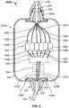
- optical fiber termination system 100includes optical fiber cable and termination unit assembly 110 and enclosure 150 .
- Assembly 110generally includes housing 112 , a plurality of optical devices enclosed by the housing, input optical fiber cable 120 , and a plurality of output optical fibers 130 A- 130 F.
- the plurality of optical devicesincludes optical splitter 116 , which may be but is not limited to being a Fused Biconical Taper (FBT) splitter, a Planar Lightwave Circuit (PLC) splitter, a multiplexer, or other like function optical function device, and patch panel terminal 140 .
- the housing 112may further include optical, optical/electronic or electronic devices coupled to the splitter 116 , for performing optical and electronic signal processing based on signals obtained from an input optical signal from the cable 120 .
- Optical splitter 116which may be an N ⁇ M power splitter or wavelength (de) multiplexer, is a passive optical device that divides a light beam supplied from input optical fiber 122 (or alternatively, input mating device 114 ) into a plurality of divided beams on optical fibers 116 A- 116 F.
- Terminals 142 A- 142 F of patch panel terminal 140may be oriented to receive respective optical fibers 116 A- 116 F from optical splitter 116 (or in alternative arrangements divided beams in free space) and, in response to receiving the respective beams, may be configured to provide respective optical signals to the respective terminals.
- input coupling tube or element 125may act as a boot that covers a portion of input optical fiber cable 120 , and in some instances input outer sheath 124 , adjacent to the location at which input optical fiber 122 (or, in alternative arrangements as described previously herein, a plurality of input optical fibers 122 A- 122 C) enters housing 112 through an input hole in the housing.
- Input coupling tube 125may abut or nearly abut housing 112 in forming a watertight seal against the housing.
- a “watertight seal”is one that is compliant with IP68, corresponding to IEC Standard 60529.
- Groove 126 of input coupling tube 125may have a width along a longitudinal axis of input coupling tube 125 that is less than or equal to a wall thickness at the portion of the housing defining the input hole such that an interference fit is created upon receipt of the housing in the groove of the input coupling tube to form the watertight seal.
- Input coupling tube 125may have a stiffness sufficient to prevent bending to preserve a minimum bending radius or twisting of input optical fiber 122 .
- inner seal 127extends between input coupling tube 125 and optical fiber cable 120 .
- Inner seal 127is preferably made of a rubber material and is more elastic than input coupling tube 125 to provide a watertight seal between inner seal 127 and optical fiber cable 120 and between inner seal 127 and input coupling tube 125 .
- Flange 119 A of housing 112extends in a direction towards the interior of the housing and is threaded.
- Lock ring 128 Ais threaded onto flange 119 A of housing 112 such that the lock ring compresses input coupling tube 125 against housing 112 and inner seal 127 against input coupling tube 125 as shown to provide an additional sealing configuration.
- output coupling tube 160may abut or nearly abut housing 112 in forming a watertight seal against the housing about an entire perimeter of an output hole through the housing through which the plurality of output optical fibers 130 A- 130 F extend. Additionally, output coupling tube 160 may interface with enclosure 150 in the same or substantially the same manner as it interfaces with housing 112 . In this manner, output coupling tube 160 may abut or nearly abut enclosure 150 to form a watertight seal against the enclosure about an entire perimeter of an enclosure hole through the enclosure through which the plurality of output optical fibers 130 A- 130 F further extend.
- output coupling tube 160is configured and attaches to housing 112 as well as enclosure 150 in the same manner as input coupling tube 125 attaches to housing 112 with the exception that no inner seal such as inner seal 127 is used with output coupling tube 160 due to its connection between enclosure 150 and housing 112 .
- lock ring 128 B attached to flange 119 Bonly compresses output coupling tube 160 against housing 112 and lock ring 158 attached to flange 159 only compresses output coupling tube 160 against enclosure 150 .
- optical fiber termination system 200may include optical fiber cable and termination unit assembly 210 and enclosure 150 .
- Assembly 210is the same as optical fiber cable and termination unit assembly 110 with the notable exception that output coupling tube 160 is replaced by output outer sheath 235 , cable connector 270 , output inner coupling tube or element 260 , and output outer coupling tube or element 265 .
- the plurality of output optical fibers 130 A- 130 Fextend from housing 112 through output outer sheath 235 and cable connector 270 which may be attached to enclosure 150 via a screw connection or other modes of attachment known to those of ordinary skill in the art.
- Output inner coupling tube 260which is substantially similar to input coupling tube 125 may interface with housing 112 in the same or substantially the same manner as input coupling tube 125 and output coupling tube 160 of input optical fiber cable 120 described previously herein. In this manner, output inner coupling tube 260 may abut or nearly abut housing 112 in forming a watertight seal against the housing about an entire perimeter of the output hole through the housing through which the plurality of output optical fibers 130 A- 130 F extend.
- Output outer coupling tube 265may act as a boot that covers a portion of output inner coupling tube 260 adjacent to the location at which the plurality of output optical fibers 130 A- 130 F extend from housing 112 .
- Output outer coupling tube 265may include a neck at a location spaced from housing 112 that may have a smaller perimeter than other sections of the outer coupling tube along its length. In this manner, the neck of outer coupling tube 265 may conform to a perimeter of output outer sheath 235 or a perimeter of output inner coupling tube 260 , or both, to form a watertight seal.
- optical fiber termination system 200 Amay include optical fiber cable and termination unit assembly 210 A and enclosure 150 .
- Assembly 210 Ais the same as optical fiber cable and termination unit assembly 210 with the notable exception that, output inner coupling tube or element 260 is replaced by output inner coupling tube 260 A, and output outer coupling tube or element 265 is replaced by output outer coupling tube 266 .
- Output inner coupling tube 260 Ais the same as or substantially the same as output inner coupling tube 260 with the exception that output inner coupling tube 260 A includes groove 262 .
- Output outer coupling tube 266is shaped such that, when placed properly against housing 112 , an end of output outer coupling tube furthest from the housing has a smaller inner diameter than the opposite end of the output outer coupling tube.
- Output outer coupling tube 266includes flange 267 that corresponds to groove 262 of output inner coupling tube 260 A such that when the output outer coupling tube and the output inner coupling tube are properly seated, flange 267 of the output outer coupling tube is seated in groove 262 , as shown in FIG. 3 . In this manner, a watertight seal is formed between inner output coupling tube 260 A and output outer coupling tube 266 .
- optical splitter 116which routes the divided beams along respective optical fibers 116 A- 116 F to respective terminals 142 A- 142 F of patch panel terminal 140 .
- Respective terminals 142 A- 142 Fthen route respective light beams from optical fibers 116 A- 116 F along output optical fibers 130 A- 130 F to fiber optic terminals, such as fiber optic terminals 152 , 154 , within enclosure 150 .
- the respective light beams from optical fibers 116 A- 116 Fmay undergo optical signal processing, and also electrical signal processing if converted to respective electric signals, which may include routing through switches, or other electrical or optical pathways, which control routing of the optical and/or electrical signals.
- optical fiber cable and termination unit assembly 310which along with enclosure 150 may form part of an optical fiber termination system, may have the configuration of either optical fiber cable and termination unit assembly 110 or optical fiber cable and termination unit assembly 110 with the exception that assembly 310 includes input coupling element 325 .
- Input coupling element 325includes outer boot 326 , inner boot 327 , inner lock ring 328 which may be tapered, and outer lock ring 329 attached to housing 112 .
- Inner boot 327may be an o-ring as in the example shown or may be integral with outer boot 326 such that the inner and outer boots are inseparable without fracture of either one or both of the inner and outer boots.
- inner lock ring 328 and outer lock ring 329may be attached by a threaded connection.
- Inner boot 327may be situated between the taper of the inner lock ring 328 and housing 112 about the input hole of the housing through which input optical fiber cable 320 , which may be a “pushable” cable, including connector 321 may extend.
- input optical fiber cable 320which may be a “pushable” cable, including connector 321 may extend.
- a portion of input optical fiber cable 320may be inserted into input coupling element 325 , as shown in FIG. 4A , and then connector 321 of the input optical fiber cable may be inserted into splitter 116 (see FIGS. 1-3 ).
- inner lock ring 328may be rotated to cause the inner lock ring to travel towards an interior surface of housing 112 .
- inner lock ring 328which may be rigid, may compress inner boot 327 causing the inner boot to form a watertight seal around a portion of input optical fiber cable 120 , as shown in FIG. 4B .
- the configuration of input coupling element 325could also be applied to an alternative arrangement of an output coupling element and its interface with housing 112 as well as its interface, or an interface with a separate coupling element having the same configuration, with enclosure 150 .
- multiple connectors of respective multiple optical fiber cables like that of input optical fiber cable 320may be inserted directly into respective terminals of patch panel terminal 140 .
- an operatorIn assembling optical fiber termination system 100 , 200 , an operator, such as but not limited to an optoelectronic technician or an electrician, may connect the plurality of output optical fibers 130 A- 130 F to respective terminals within enclosure 150 . The operator may then attach output coupling tube 160 of optical fiber cable and termination unit assembly 110 to enclosure 150 , as in the example of optical fiber termination system 100 , or attach cable connector 270 of either of optical fiber cable and termination unit assemblies 210 , 210 A to enclosure 150 , as in the example of optical fiber termination systems 200 , 210 A, respectively.
- the output optical fiber cablesmay be replaced with electrically conductive wires.
- the electrically conductive wiresmay be electrically connected to the patch panel terminal within the housing of the cable and termination unit assembly and the electronic devices or equipment within the enclosure.
- the patch panel terminalmay route or transmit electrical signals or an optical-to-electrical converter (which in some instances may be integrated with the patch panel terminal) optically connected to the patch panel terminal by shortened output optical fibers may route or transmit electrical signals, and in some arrangements electrical power, to respective electronic devices or equipment in the enclosure.
- the input optical fiber cable or the plurality of output optical fibersmay be replaced with “pushable” cables as described previously herein with respect to the example of FIGS. 4A, 4B .
- the input optical fibermay be inserted directly into the splitter and the plurality of output optical fiber cables may be inserted into respective terminals of the patch panel terminal.
Landscapes
- Physics & Mathematics (AREA)
- General Physics & Mathematics (AREA)
- Optics & Photonics (AREA)
- Light Guides In General And Applications Therefor (AREA)
- Optical Couplings Of Light Guides (AREA)
Abstract
Description
Claims (21)
Priority Applications (1)
| Application Number | Priority Date | Filing Date | Title |
|---|---|---|---|
| US16/849,527US11042002B2 (en) | 2017-05-04 | 2020-04-15 | Cable termination assembly |
Applications Claiming Priority (4)
| Application Number | Priority Date | Filing Date | Title |
|---|---|---|---|
| US201762501639P | 2017-05-04 | 2017-05-04 | |
| PCT/US2018/031219WO2018204864A1 (en) | 2017-05-04 | 2018-05-04 | Cable termination assembly |
| US201916325330A | 2019-02-13 | 2019-02-13 | |
| US16/849,527US11042002B2 (en) | 2017-05-04 | 2020-04-15 | Cable termination assembly |
Related Parent Applications (2)
| Application Number | Title | Priority Date | Filing Date |
|---|---|---|---|
| PCT/US2018/031219ContinuationWO2018204864A1 (en) | 2017-05-04 | 2018-05-04 | Cable termination assembly |
| US16/325,330ContinuationUS10656361B2 (en) | 2017-05-04 | 2018-05-04 | Cable termination assembly |
Publications (2)
| Publication Number | Publication Date |
|---|---|
| US20200241230A1 US20200241230A1 (en) | 2020-07-30 |
| US11042002B2true US11042002B2 (en) | 2021-06-22 |
Family
ID=64017060
Family Applications (2)
| Application Number | Title | Priority Date | Filing Date |
|---|---|---|---|
| US16/325,330Expired - Fee RelatedUS10656361B2 (en) | 2017-05-04 | 2018-05-04 | Cable termination assembly |
| US16/849,527Expired - Fee RelatedUS11042002B2 (en) | 2017-05-04 | 2020-04-15 | Cable termination assembly |
Family Applications Before (1)
| Application Number | Title | Priority Date | Filing Date |
|---|---|---|---|
| US16/325,330Expired - Fee RelatedUS10656361B2 (en) | 2017-05-04 | 2018-05-04 | Cable termination assembly |
Country Status (2)
| Country | Link |
|---|---|
| US (2) | US10656361B2 (en) |
| WO (1) | WO2018204864A1 (en) |
Families Citing this family (26)
| Publication number | Priority date | Publication date | Assignee | Title |
|---|---|---|---|---|
| WO2018204864A1 (en) | 2017-05-04 | 2018-11-08 | Go!Foton Holding, Inc. | Cable termination assembly |
| US11300746B2 (en) | 2017-06-28 | 2022-04-12 | Corning Research & Development Corporation | Fiber optic port module inserts, assemblies and methods of making the same |
| US10359577B2 (en) | 2017-06-28 | 2019-07-23 | Corning Research & Development Corporation | Multiports and optical connectors with rotationally discrete locking and keying features |
| CN111051945B (en) | 2017-06-28 | 2023-12-29 | 康宁研究与开发公司 | Compact fiber optic connector, cable assembly and method of making the same |
| US11187859B2 (en) | 2017-06-28 | 2021-11-30 | Corning Research & Development Corporation | Fiber optic connectors and methods of making the same |
| US11668890B2 (en) | 2017-06-28 | 2023-06-06 | Corning Research & Development Corporation | Multiports and other devices having optical connection ports with securing features and methods of making the same |
| US12271040B2 (en) | 2017-06-28 | 2025-04-08 | Corning Research & Development Corporation | Fiber optic extender ports, assemblies and methods of making the same |
| US11480751B2 (en)* | 2017-07-31 | 2022-10-25 | Commscope Technologies Llc | Optical fiber cable fanout arrangements, components, and methods |
| US11703651B2 (en) | 2018-11-02 | 2023-07-18 | Go!Foton Holdings, Inc. | Cable termination assembly with disengagement prevention structures |
| US11531170B2 (en) | 2018-11-28 | 2022-12-20 | Go!Foton Holdings, Inc. | Intelligent patch panel |
| PT3903136T (en) | 2018-12-28 | 2024-12-05 | Corning Res & Dev Corp | Multiport assemblies including mounting features or dust plugs |
| WO2020210638A1 (en)* | 2019-04-12 | 2020-10-15 | Commscope Technologies Llc | Extender system for telecommunications enclosures |
| WO2020242847A1 (en) | 2019-05-31 | 2020-12-03 | Corning Research & Development Corporation | Multiports and other devices having optical connection ports with sliding actuators and methods of making the same |
| US11294133B2 (en) | 2019-07-31 | 2022-04-05 | Corning Research & Development Corporation | Fiber optic networks using multiports and cable assemblies with cable-to-connector orientation |
| US11487073B2 (en) | 2019-09-30 | 2022-11-01 | Corning Research & Development Corporation | Cable input devices having an integrated locking feature and assemblies using the cable input devices |
| EP3805827B1 (en) | 2019-10-07 | 2025-07-30 | Corning Research & Development Corporation | Fiber optic terminals and fiber optic networks having variable ratio couplers |
| US11650388B2 (en) | 2019-11-14 | 2023-05-16 | Corning Research & Development Corporation | Fiber optic networks having a self-supporting optical terminal and methods of installing the optical terminal |
| US11536921B2 (en) | 2020-02-11 | 2022-12-27 | Corning Research & Development Corporation | Fiber optic terminals having one or more loopback assemblies |
| US11604320B2 (en) | 2020-09-30 | 2023-03-14 | Corning Research & Development Corporation | Connector assemblies for telecommunication enclosures |
| AU2021368055A1 (en) | 2020-10-30 | 2023-06-08 | Corning Research & Development Corporation | Female fiber optic connectors having a rocker latch arm and methods of making the same |
| US11880076B2 (en) | 2020-11-30 | 2024-01-23 | Corning Research & Development Corporation | Fiber optic adapter assemblies including a conversion housing and a release housing |
| US11686913B2 (en) | 2020-11-30 | 2023-06-27 | Corning Research & Development Corporation | Fiber optic cable assemblies and connector assemblies having a crimp ring and crimp body and methods of fabricating the same |
| US11994722B2 (en) | 2020-11-30 | 2024-05-28 | Corning Research & Development Corporation | Fiber optic adapter assemblies including an adapter housing and a locking housing |
| US11927810B2 (en) | 2020-11-30 | 2024-03-12 | Corning Research & Development Corporation | Fiber optic adapter assemblies including a conversion housing and a release member |
| US12153270B2 (en)* | 2021-01-15 | 2024-11-26 | Go!Foton Holdings, Inc. | Drop cable box |
| US11947167B2 (en) | 2021-05-26 | 2024-04-02 | Corning Research & Development Corporation | Fiber optic terminals and tools and methods for adjusting a split ratio of a fiber optic terminal |
Citations (64)
| Publication number | Priority date | Publication date | Assignee | Title |
|---|---|---|---|---|
| US413245A (en) | 1889-10-22 | richmond | ||
| US732450A (en) | 1903-01-02 | 1903-06-30 | Henry W Schiermeyer | Latch. |
| US983647A (en) | 1910-02-16 | 1911-02-07 | Leroy Romines | Latch. |
| US3252746A (en) | 1964-08-13 | 1966-05-24 | Corry Jamestown Corp | Filing cabinet and latching mechanism |
| US4061371A (en) | 1976-02-17 | 1977-12-06 | Edson Tool & Manufacturing Company, Inc. | Self-locking devices |
| US4254865A (en) | 1979-10-02 | 1981-03-10 | Northern Telecom Limited | Protective package for an optical fiber splice |
| US4549038A (en) | 1983-08-22 | 1985-10-22 | Ideal Industries, Inc. | Cord grip |
| US4789217A (en) | 1987-05-05 | 1988-12-06 | Tektronix, Inc. | Method of and apparatus for securing elongate members of generally cylindrical form in end-to-end relationship |
| US4805979A (en) | 1987-09-04 | 1989-02-21 | Minnesota Mining And Manufacturing Company | Fiber optic cable splice closure |
| US4900118A (en) | 1987-05-22 | 1990-02-13 | Furukawa Electric Co., Ltd. | Multiple-fiber optical component and method for manufacturing of the same |
| US4965414A (en) | 1989-03-31 | 1990-10-23 | Cooper Industries, Inc. | Circuit breaker and reset mechanisms operated through the body |
| US5005942A (en) | 1989-09-05 | 1991-04-09 | Gte Products Corporation | Fiber optic splice assembly |
| US5189717A (en) | 1988-04-18 | 1993-02-23 | Minnesota Mining And Manufacturing Company | Optical fiber splice |
| US5239129A (en) | 1992-04-06 | 1993-08-24 | Hubbell Incorporated | Housing for switched electrical receptacle or the like |
| US5286935A (en) | 1993-04-22 | 1994-02-15 | Appleton Electric Company | Self-locating, prepositioning actuator for an electrical switch enclosure |
| US5403976A (en) | 1992-09-21 | 1995-04-04 | Zedel | Electrical casing with tight passage for a power supply cable |
| US6116793A (en) | 1997-04-09 | 2000-09-12 | Siemens Aktiengesellschaft | Splice protection device, a receptacle device for light waveguides and an arrangement for placing the light waveguides into the splice protection device |
| US6300569B1 (en) | 1997-02-13 | 2001-10-09 | Heyco Products, Inc. | 90° sealing nut |
| US6424781B1 (en) | 1999-03-01 | 2002-07-23 | Adc Telecommunications, Inc. | Optical fiber distribution frame with pivoting connector panels |
| US6527353B1 (en) | 2000-09-08 | 2003-03-04 | Darrell R. Bradfish | Latch handle for doors and drawers |
| US20030103750A1 (en) | 2001-11-30 | 2003-06-05 | Laporte Richard B. | Distribution terminal for network access point |
| US6621951B1 (en) | 2000-06-27 | 2003-09-16 | Oluma, Inc. | Thin film structures in devices with a fiber on a substrate |
| US20040211774A1 (en) | 2003-04-23 | 2004-10-28 | Lucent Technologies Inc. | Fiber closure sealing apparatus |
| US6935661B1 (en) | 2000-11-21 | 2005-08-30 | Hewlett-Packard Development Company, L.P. | Access panel latching system |
| US20060067637A1 (en) | 2004-09-24 | 2006-03-30 | 3M Innovative Properties Company | Splice holder device |
| US20060093303A1 (en) | 2004-11-03 | 2006-05-04 | Randy Reagan | Fiber drop terminal |
| US20070189692A1 (en) | 2006-02-13 | 2007-08-16 | Zimmel Steven C | Fiber optic splitter module |
| US7291032B1 (en) | 2006-07-05 | 2007-11-06 | International Business Machines Corporation | Connector for adjacent devices |
| US20080226250A1 (en) | 2007-03-15 | 2008-09-18 | Curtis Paul Gonzales | Fiber optic categorization and management tray |
| US20090166404A1 (en) | 2008-01-02 | 2009-07-02 | Commscope, Inc. Of North Carolina | Intelligent MPO-to-MPO Patch Panels Having Connectivity Tracking Capabilities and Related Methods |
| US7595455B2 (en) | 2002-02-21 | 2009-09-29 | Wayne H. Robinson | Kenny clamp |
| US20100038130A1 (en) | 2006-10-27 | 2010-02-18 | Jingwen Zhong | Re-enterable splice enclosure |
| US20100109892A1 (en) | 2008-11-05 | 2010-05-06 | Commscope, Inc. | Intelligent Patch Panel Sensor Modules Having Infrared Emitters and Sensors for Detecting Patch Cords |
| US20100183276A1 (en) | 2009-01-20 | 2010-07-22 | Smith Trevor D | Splitter Module with Connectorized Pigtail Manager |
| US20100322580A1 (en) | 2009-06-22 | 2010-12-23 | Beamon Hubert B | Fiber Optic Cable Parking Device |
| US20110217017A1 (en) | 2008-10-30 | 2011-09-08 | Patrick Drouard | Sealing enclosure |
| US20120037416A1 (en) | 2010-08-11 | 2012-02-16 | Jiun Wei Chiou | Double-packing cable and flexible conduit gland |
| US20120051707A1 (en) | 2010-08-30 | 2012-03-01 | Barnes Ray S | Methods, Apparatuses for Providing Secure Fiber Optic Connections |
| US20120224823A1 (en) | 2011-03-04 | 2012-09-06 | Terry Dean Cox | Fiber optic adapter mount |
| US8313250B2 (en) | 2008-04-09 | 2012-11-20 | 3M Innovative Properties Company | Telecommunications cable inlet device |
| US20120328251A1 (en) | 2011-06-24 | 2012-12-27 | Kenichiro Takeuchi | Mechanical Splicer Apparatus for Fiber Optic Cables |
| US20130004136A1 (en) | 2011-06-30 | 2013-01-03 | Boyd Grant Brower | Fiber optic equipment assemblies employing non-u-width-sized housings and related methods |
| US20130008594A1 (en) | 2011-07-06 | 2013-01-10 | Kenichiro Takeuchi | Apparatus and Method for Mass Producing Optical Fiber Splice-On Connector Subunits |
| US20130022324A1 (en) | 2011-07-21 | 2013-01-24 | Kenichiro Takeuchi | Deformable Plastic Radially Symmetric Mechanical Splicers and Connectors for Optical Fibers |
| US20130064506A1 (en) | 2011-09-12 | 2013-03-14 | Tyco Electronics Corporation | Flexible lensed optical interconnect device for signal distribution |
| US20130196538A1 (en) | 2012-01-27 | 2013-08-01 | Go!Foton Holdings, Inc. | Patch panel assembly |
| US8550722B2 (en) | 2004-06-22 | 2013-10-08 | Welldynamics, B.V. | Fiber optic splice housing and integral dry mate connector system |
| US8556356B2 (en) | 2011-02-21 | 2013-10-15 | Commscope, Inc. Of North Carolina | Communication shelf having supports for pivotable adapter panels and method of mounting adapter panels therein |
| US8672428B2 (en) | 2011-10-24 | 2014-03-18 | Go!Foton Holdings, Inc. | Housing for optical elements |
| US8920050B2 (en) | 2011-06-24 | 2014-12-30 | Go!Foton Holdings, Inc. | Termination assembly for alignment of optical fibers |
| US20150155696A1 (en) | 2012-07-02 | 2015-06-04 | Tyco Electronics Raychem Bvba | Re-enterable enclosure |
| US9323020B2 (en) | 2008-10-09 | 2016-04-26 | Corning Cable Systems (Shanghai) Co. Ltd | Fiber optic terminal having adapter panel supporting both input and output fibers from an optical splitter |
| US20160178859A1 (en) | 2014-12-19 | 2016-06-23 | 3M Innovative Properties Company | Ruggedized optical fiber connection structures and assemblies |
| US9525483B2 (en) | 2015-03-17 | 2016-12-20 | Verizon Patent And Licensing Inc. | Actively monitored optical fiber panel |
| US20170003459A1 (en) | 2015-07-01 | 2017-01-05 | Go!Foton Holdings, Inc. | Connector engagement sensing mechanism |
| US20170097471A1 (en)* | 2014-12-31 | 2017-04-06 | Commscope, Inc. Of North Carolina | Trunk gland adapters and related trunk gland units and methods of connecting trunk cables to fiber optic enclosures |
| US20170195051A1 (en) | 2014-06-24 | 2017-07-06 | Sony Corporation | Optical transmitter, optical receiver, optical cable and light transmission method |
| US20170235067A1 (en) | 2008-01-09 | 2017-08-17 | Commscope Technologies Llc | Wall box adapted to be mounted at a mid-span access location of a telecommunications cable |
| USRE46780E1 (en) | 2009-06-08 | 2018-04-10 | Commscope, Inc. Of North Carolina | High density patching system for cable and optical fiber |
| US20180136410A1 (en) | 2015-07-01 | 2018-05-17 | Go!Foton Holdings, Inc. | Connector engagement sensing mechanism |
| US10048452B1 (en)* | 2017-06-28 | 2018-08-14 | Sumitomo Electric Lightwave Corp. | System and method for joining and distributing a single optical fiber cable to multiple rack shelves |
| WO2018204864A1 (en) | 2017-05-04 | 2018-11-08 | Go!Foton Holding, Inc. | Cable termination assembly |
| US10281670B2 (en) | 2015-01-12 | 2019-05-07 | Afl Telecommunications Llc | Fiber optic terminal enclosure |
| WO2020091823A1 (en) | 2018-11-02 | 2020-05-07 | Go!Foton Holdings, Inc. | Cable termination assembly with disengagement prevention structures |
- 2018
- 2018-05-04WOPCT/US2018/031219patent/WO2018204864A1/ennot_activeCeased
- 2018-05-04USUS16/325,330patent/US10656361B2/ennot_activeExpired - Fee Related
- 2020
- 2020-04-15USUS16/849,527patent/US11042002B2/ennot_activeExpired - Fee Related
Patent Citations (66)
| Publication number | Priority date | Publication date | Assignee | Title |
|---|---|---|---|---|
| US413245A (en) | 1889-10-22 | richmond | ||
| US732450A (en) | 1903-01-02 | 1903-06-30 | Henry W Schiermeyer | Latch. |
| US983647A (en) | 1910-02-16 | 1911-02-07 | Leroy Romines | Latch. |
| US3252746A (en) | 1964-08-13 | 1966-05-24 | Corry Jamestown Corp | Filing cabinet and latching mechanism |
| US4061371A (en) | 1976-02-17 | 1977-12-06 | Edson Tool & Manufacturing Company, Inc. | Self-locking devices |
| US4254865A (en) | 1979-10-02 | 1981-03-10 | Northern Telecom Limited | Protective package for an optical fiber splice |
| US4549038A (en) | 1983-08-22 | 1985-10-22 | Ideal Industries, Inc. | Cord grip |
| US4789217A (en) | 1987-05-05 | 1988-12-06 | Tektronix, Inc. | Method of and apparatus for securing elongate members of generally cylindrical form in end-to-end relationship |
| US4900118A (en) | 1987-05-22 | 1990-02-13 | Furukawa Electric Co., Ltd. | Multiple-fiber optical component and method for manufacturing of the same |
| US4805979A (en) | 1987-09-04 | 1989-02-21 | Minnesota Mining And Manufacturing Company | Fiber optic cable splice closure |
| US5189717A (en) | 1988-04-18 | 1993-02-23 | Minnesota Mining And Manufacturing Company | Optical fiber splice |
| US4965414A (en) | 1989-03-31 | 1990-10-23 | Cooper Industries, Inc. | Circuit breaker and reset mechanisms operated through the body |
| US5005942A (en) | 1989-09-05 | 1991-04-09 | Gte Products Corporation | Fiber optic splice assembly |
| US5239129A (en) | 1992-04-06 | 1993-08-24 | Hubbell Incorporated | Housing for switched electrical receptacle or the like |
| US5403976A (en) | 1992-09-21 | 1995-04-04 | Zedel | Electrical casing with tight passage for a power supply cable |
| US5286935A (en) | 1993-04-22 | 1994-02-15 | Appleton Electric Company | Self-locating, prepositioning actuator for an electrical switch enclosure |
| US6300569B1 (en) | 1997-02-13 | 2001-10-09 | Heyco Products, Inc. | 90° sealing nut |
| US6116793A (en) | 1997-04-09 | 2000-09-12 | Siemens Aktiengesellschaft | Splice protection device, a receptacle device for light waveguides and an arrangement for placing the light waveguides into the splice protection device |
| US6424781B1 (en) | 1999-03-01 | 2002-07-23 | Adc Telecommunications, Inc. | Optical fiber distribution frame with pivoting connector panels |
| US6621951B1 (en) | 2000-06-27 | 2003-09-16 | Oluma, Inc. | Thin film structures in devices with a fiber on a substrate |
| US6527353B1 (en) | 2000-09-08 | 2003-03-04 | Darrell R. Bradfish | Latch handle for doors and drawers |
| US6935661B1 (en) | 2000-11-21 | 2005-08-30 | Hewlett-Packard Development Company, L.P. | Access panel latching system |
| US20030103750A1 (en) | 2001-11-30 | 2003-06-05 | Laporte Richard B. | Distribution terminal for network access point |
| US7595455B2 (en) | 2002-02-21 | 2009-09-29 | Wayne H. Robinson | Kenny clamp |
| US20040211774A1 (en) | 2003-04-23 | 2004-10-28 | Lucent Technologies Inc. | Fiber closure sealing apparatus |
| US8550722B2 (en) | 2004-06-22 | 2013-10-08 | Welldynamics, B.V. | Fiber optic splice housing and integral dry mate connector system |
| US20060067637A1 (en) | 2004-09-24 | 2006-03-30 | 3M Innovative Properties Company | Splice holder device |
| US20060093303A1 (en) | 2004-11-03 | 2006-05-04 | Randy Reagan | Fiber drop terminal |
| US20070189692A1 (en) | 2006-02-13 | 2007-08-16 | Zimmel Steven C | Fiber optic splitter module |
| US7291032B1 (en) | 2006-07-05 | 2007-11-06 | International Business Machines Corporation | Connector for adjacent devices |
| US20100038130A1 (en) | 2006-10-27 | 2010-02-18 | Jingwen Zhong | Re-enterable splice enclosure |
| US20080226250A1 (en) | 2007-03-15 | 2008-09-18 | Curtis Paul Gonzales | Fiber optic categorization and management tray |
| US20090166404A1 (en) | 2008-01-02 | 2009-07-02 | Commscope, Inc. Of North Carolina | Intelligent MPO-to-MPO Patch Panels Having Connectivity Tracking Capabilities and Related Methods |
| US20170235067A1 (en) | 2008-01-09 | 2017-08-17 | Commscope Technologies Llc | Wall box adapted to be mounted at a mid-span access location of a telecommunications cable |
| US8313250B2 (en) | 2008-04-09 | 2012-11-20 | 3M Innovative Properties Company | Telecommunications cable inlet device |
| US9323020B2 (en) | 2008-10-09 | 2016-04-26 | Corning Cable Systems (Shanghai) Co. Ltd | Fiber optic terminal having adapter panel supporting both input and output fibers from an optical splitter |
| US20110217017A1 (en) | 2008-10-30 | 2011-09-08 | Patrick Drouard | Sealing enclosure |
| US20100109892A1 (en) | 2008-11-05 | 2010-05-06 | Commscope, Inc. | Intelligent Patch Panel Sensor Modules Having Infrared Emitters and Sensors for Detecting Patch Cords |
| US8380036B2 (en) | 2009-01-20 | 2013-02-19 | Adc Telecommunications, Inc. | Splitter module with connectorized pigtail manager |
| US20100183276A1 (en) | 2009-01-20 | 2010-07-22 | Smith Trevor D | Splitter Module with Connectorized Pigtail Manager |
| USRE46780E1 (en) | 2009-06-08 | 2018-04-10 | Commscope, Inc. Of North Carolina | High density patching system for cable and optical fiber |
| US20100322580A1 (en) | 2009-06-22 | 2010-12-23 | Beamon Hubert B | Fiber Optic Cable Parking Device |
| US20120037416A1 (en) | 2010-08-11 | 2012-02-16 | Jiun Wei Chiou | Double-packing cable and flexible conduit gland |
| US20120051707A1 (en) | 2010-08-30 | 2012-03-01 | Barnes Ray S | Methods, Apparatuses for Providing Secure Fiber Optic Connections |
| US8556356B2 (en) | 2011-02-21 | 2013-10-15 | Commscope, Inc. Of North Carolina | Communication shelf having supports for pivotable adapter panels and method of mounting adapter panels therein |
| US20120224823A1 (en) | 2011-03-04 | 2012-09-06 | Terry Dean Cox | Fiber optic adapter mount |
| US8920050B2 (en) | 2011-06-24 | 2014-12-30 | Go!Foton Holdings, Inc. | Termination assembly for alignment of optical fibers |
| US20120328251A1 (en) | 2011-06-24 | 2012-12-27 | Kenichiro Takeuchi | Mechanical Splicer Apparatus for Fiber Optic Cables |
| US20130004136A1 (en) | 2011-06-30 | 2013-01-03 | Boyd Grant Brower | Fiber optic equipment assemblies employing non-u-width-sized housings and related methods |
| US20130008594A1 (en) | 2011-07-06 | 2013-01-10 | Kenichiro Takeuchi | Apparatus and Method for Mass Producing Optical Fiber Splice-On Connector Subunits |
| US20130022324A1 (en) | 2011-07-21 | 2013-01-24 | Kenichiro Takeuchi | Deformable Plastic Radially Symmetric Mechanical Splicers and Connectors for Optical Fibers |
| US20130064506A1 (en) | 2011-09-12 | 2013-03-14 | Tyco Electronics Corporation | Flexible lensed optical interconnect device for signal distribution |
| US8672428B2 (en) | 2011-10-24 | 2014-03-18 | Go!Foton Holdings, Inc. | Housing for optical elements |
| US20130196538A1 (en) | 2012-01-27 | 2013-08-01 | Go!Foton Holdings, Inc. | Patch panel assembly |
| US20150155696A1 (en) | 2012-07-02 | 2015-06-04 | Tyco Electronics Raychem Bvba | Re-enterable enclosure |
| US20170195051A1 (en) | 2014-06-24 | 2017-07-06 | Sony Corporation | Optical transmitter, optical receiver, optical cable and light transmission method |
| US20160178859A1 (en) | 2014-12-19 | 2016-06-23 | 3M Innovative Properties Company | Ruggedized optical fiber connection structures and assemblies |
| US20170097471A1 (en)* | 2014-12-31 | 2017-04-06 | Commscope, Inc. Of North Carolina | Trunk gland adapters and related trunk gland units and methods of connecting trunk cables to fiber optic enclosures |
| US10281670B2 (en) | 2015-01-12 | 2019-05-07 | Afl Telecommunications Llc | Fiber optic terminal enclosure |
| US9525483B2 (en) | 2015-03-17 | 2016-12-20 | Verizon Patent And Licensing Inc. | Actively monitored optical fiber panel |
| US20180136410A1 (en) | 2015-07-01 | 2018-05-17 | Go!Foton Holdings, Inc. | Connector engagement sensing mechanism |
| US20170003459A1 (en) | 2015-07-01 | 2017-01-05 | Go!Foton Holdings, Inc. | Connector engagement sensing mechanism |
| WO2018204864A1 (en) | 2017-05-04 | 2018-11-08 | Go!Foton Holding, Inc. | Cable termination assembly |
| US10656361B2 (en) | 2017-05-04 | 2020-05-19 | Go!Foton Holdings, Inc. | Cable termination assembly |
| US10048452B1 (en)* | 2017-06-28 | 2018-08-14 | Sumitomo Electric Lightwave Corp. | System and method for joining and distributing a single optical fiber cable to multiple rack shelves |
| WO2020091823A1 (en) | 2018-11-02 | 2020-05-07 | Go!Foton Holdings, Inc. | Cable termination assembly with disengagement prevention structures |
Non-Patent Citations (12)
| Title |
|---|
| "FieldShield YOURx-Terminal: Installation Manual", Clearfield, Jul. 2017, 33 pages. |
| "Guide to Fiber Optics & Premises Cabling", The Fiber Optic Association, Inc., http://www.thefoa.org/tech/ref/OSP/term.html, 2015, 27 pages. |
| "S918A Temporary Fiber Aligner," <http://www.fitel.k2international.net/Fitel_S612_Fixture_files/S612%20Ribbon%20Forming%20Fixture.pdf>, dated Sep. 10, 2008. |
| "YOURx-Aerial Terminal: Installation Manual", Clearfield, Sep. 2018, 29 pages. |
| "YOURx-Aerial Terminal—Patch and Splice", Clearfield, Aug. 31, 2018, 4 pages. |
| "YOURx-Terminal", Clearfield, Oct. 29, 2018, 7 pages. |
| Corrected International Search Report with Written Opinion for Application No. PCT/US2019/00063 dated Apr. 7, 2020, 22 pages. |
| Excerpt of ISE Magazine, vol. 36, Issue 2 (Feb. 2018). |
| International Search Report for PCT/US18/31219 dated Aug. 1, 2018. |
| International Search Report with Written Opinion for Application No. PCT/US2019/00063 dated Mar. 10, 2020, 26 pages. |
| International Search Report with Written Opinion for Application No. PCT/US2019/063749 dated Mar. 24, 2020, 17 pages. |
| Wellbrock GA, Xia TJ, Huang MF, Chen Y, Salemi M, Huang YK, Ji P, Ip E, Wang T. First field trial of sensing vehicle speed, density, and road conditions by using fiber carrying high speed data. In2019 Optical Fiber Communications Conference and Exhibition (OFC) Mar. 7, 2019 (pp. 1-3). IEEE. |
Also Published As
| Publication number | Publication date |
|---|---|
| US10656361B2 (en) | 2020-05-19 |
| US20200241230A1 (en) | 2020-07-30 |
| WO2018204864A8 (en) | 2019-11-07 |
| WO2018204864A1 (en) | 2018-11-08 |
| US20200049920A1 (en) | 2020-02-13 |
Similar Documents
| Publication | Publication Date | Title |
|---|---|---|
| US11042002B2 (en) | Cable termination assembly | |
| US11860424B2 (en) | Fiber optic/electrical connection system | |
| CN103109221B (en) | Environmentally Sealed Cable Breakout Assemblies | |
| AU2009322829B2 (en) | Hybrid connector | |
| CN101449190B (en) | Fiber Optic Cables and Fiber Optic Cable Assemblies for Wireless Access | |
| US10509188B2 (en) | System and method of fiber distribution | |
| CN102722003A (en) | Opto-electric connector | |
| CN106130646A (en) | For the method that wireless technology is integrated in fiber optic network, system and equipment | |
| US11041998B2 (en) | Telecommunication enclosures | |
| US20130022318A1 (en) | Field terminated fiber optic and electrical connection device | |
| US20180372963A1 (en) | Fiber optic cable connector for a rugged environment | |
| US11726272B2 (en) | Outdoor rated fiber optic jumper cable | |
| US9016959B2 (en) | Opto-electronic module with patchcords | |
| US6290399B1 (en) | Optical submarine branching unit | |
| EP2423721B1 (en) | Adapter for receiving a hybrid connector part and a fiber optic connector part | |
| US9977202B2 (en) | Optical multichannel transmission and/or reception module, in particular for high-bitrate digital optical signals | |
| US20100266235A1 (en) | Planar lightwave apparatus | |
| KR20020061866A (en) | Fanout cord having multifiber branching device with optical fiber block connection part | |
| KR100441661B1 (en) | Fanout cord | |
| KR200358258Y1 (en) | Mini Fiberoptic Splicing Module | |
| KR101760290B1 (en) | Optical and Electrical Hybrid Connector and Adapter | |
| WO2017015213A1 (en) | System for field switching of telecommunications services to provide service upgrades or other service modifications |
Legal Events
| Date | Code | Title | Description |
|---|---|---|---|
| FEPP | Fee payment procedure | Free format text:ENTITY STATUS SET TO UNDISCOUNTED (ORIGINAL EVENT CODE: BIG.); ENTITY STATUS OF PATENT OWNER: LARGE ENTITY | |
| STPP | Information on status: patent application and granting procedure in general | Free format text:DOCKETED NEW CASE - READY FOR EXAMINATION | |
| STPP | Information on status: patent application and granting procedure in general | Free format text:NOTICE OF ALLOWANCE MAILED -- APPLICATION RECEIVED IN OFFICE OF PUBLICATIONS | |
| STPP | Information on status: patent application and granting procedure in general | Free format text:AWAITING TC RESP., ISSUE FEE NOT PAID | |
| STPP | Information on status: patent application and granting procedure in general | Free format text:NOTICE OF ALLOWANCE MAILED -- APPLICATION RECEIVED IN OFFICE OF PUBLICATIONS | |
| STPP | Information on status: patent application and granting procedure in general | Free format text:PUBLICATIONS -- ISSUE FEE PAYMENT RECEIVED | |
| STPP | Information on status: patent application and granting procedure in general | Free format text:PUBLICATIONS -- ISSUE FEE PAYMENT VERIFIED | |
| STCF | Information on status: patent grant | Free format text:PATENTED CASE | |
| AS | Assignment | Owner name:GO!FOTON HOLDINGS, INC., NEW JERSEY Free format text:ASSIGNMENT OF ASSIGNORS INTEREST;ASSIGNORS:TAKEUCHI, KENICHIRO;LU, HAIGUANG;SIGNING DATES FROM 20200120 TO 20210618;REEL/FRAME:056584/0669 | |
| FEPP | Fee payment procedure | Free format text:MAINTENANCE FEE REMINDER MAILED (ORIGINAL EVENT CODE: REM.); ENTITY STATUS OF PATENT OWNER: LARGE ENTITY | |
| LAPS | Lapse for failure to pay maintenance fees | Free format text:PATENT EXPIRED FOR FAILURE TO PAY MAINTENANCE FEES (ORIGINAL EVENT CODE: EXP.); ENTITY STATUS OF PATENT OWNER: LARGE ENTITY | |
| STCH | Information on status: patent discontinuation | Free format text:PATENT EXPIRED DUE TO NONPAYMENT OF MAINTENANCE FEES UNDER 37 CFR 1.362 | |
| FP | Lapsed due to failure to pay maintenance fee | Effective date:20250622 |