US11041722B2 - Systems and methods for sensing angular motion in the presence of low-frequency noise - Google Patents
Systems and methods for sensing angular motion in the presence of low-frequency noiseDownload PDFInfo
- Publication number
- US11041722B2 US11041722B2US16/042,742US201816042742AUS11041722B2US 11041722 B2US11041722 B2US 11041722B2US 201816042742 AUS201816042742 AUS 201816042742AUS 11041722 B2US11041722 B2US 11041722B2
- Authority
- US
- United States
- Prior art keywords
- signal
- sense
- resonator
- demodulating
- switch
- Prior art date
- Legal status (The legal status is an assumption and is not a legal conclusion. Google has not performed a legal analysis and makes no representation as to the accuracy of the status listed.)
- Active, expires
Links
Images


Classifications
- G—PHYSICS
- G01—MEASURING; TESTING
- G01C—MEASURING DISTANCES, LEVELS OR BEARINGS; SURVEYING; NAVIGATION; GYROSCOPIC INSTRUMENTS; PHOTOGRAMMETRY OR VIDEOGRAMMETRY
- G01C19/00—Gyroscopes; Turn-sensitive devices using vibrating masses; Turn-sensitive devices without moving masses; Measuring angular rate using gyroscopic effects
- G01C19/56—Turn-sensitive devices using vibrating masses, e.g. vibratory angular rate sensors based on Coriolis forces
- G01C19/5705—Turn-sensitive devices using vibrating masses, e.g. vibratory angular rate sensors based on Coriolis forces using masses driven in reciprocating rotary motion about an axis
- G01C19/5712—Turn-sensitive devices using vibrating masses, e.g. vibratory angular rate sensors based on Coriolis forces using masses driven in reciprocating rotary motion about an axis the devices involving a micromechanical structure
- G—PHYSICS
- G01—MEASURING; TESTING
- G01C—MEASURING DISTANCES, LEVELS OR BEARINGS; SURVEYING; NAVIGATION; GYROSCOPIC INSTRUMENTS; PHOTOGRAMMETRY OR VIDEOGRAMMETRY
- G01C19/00—Gyroscopes; Turn-sensitive devices using vibrating masses; Turn-sensitive devices without moving masses; Measuring angular rate using gyroscopic effects
- G01C19/56—Turn-sensitive devices using vibrating masses, e.g. vibratory angular rate sensors based on Coriolis forces
- G01C19/5719—Turn-sensitive devices using vibrating masses, e.g. vibratory angular rate sensors based on Coriolis forces using planar vibrating masses driven in a translation vibration along an axis
- G01C19/5726—Signal processing
- G—PHYSICS
- G01—MEASURING; TESTING
- G01C—MEASURING DISTANCES, LEVELS OR BEARINGS; SURVEYING; NAVIGATION; GYROSCOPIC INSTRUMENTS; PHOTOGRAMMETRY OR VIDEOGRAMMETRY
- G01C19/00—Gyroscopes; Turn-sensitive devices using vibrating masses; Turn-sensitive devices without moving masses; Measuring angular rate using gyroscopic effects
- G01C19/56—Turn-sensitive devices using vibrating masses, e.g. vibratory angular rate sensors based on Coriolis forces
- G01C19/5719—Turn-sensitive devices using vibrating masses, e.g. vibratory angular rate sensors based on Coriolis forces using planar vibrating masses driven in a translation vibration along an axis
- G01C19/5733—Structural details or topology
- G01C19/5755—Structural details or topology the devices having a single sensing mass
Definitions
- the present applicationrelates to microelectromechanical system (MEMS) gyroscopes.
- MEMSmicroelectromechanical system
- Microelectromechanical systems (MEMS) gyroscopesare configured to detect angular motion by sensing accelerations produced by Coriolis forces. Coriolis forces arise when a resonant mass of a MEMS gyroscope is subjected to angular motion.
- Some embodimentsrelate to systems and methods for sensing angular motion using a microelectromechanical system (MEMS) gyroscope. These systems and methods may be useful for sensing angular motion in the presence of low-frequency noise, which may be noise below 1 KHz.
- low-frequency noisemay give rise to duty cycle jitter, which may affect the demodulation of the sense signal and cause errors in angular motion estimates. Such errors are often referred to as “bias instability.”
- the systems and methods described hereinaddress this problem by relying on double-edge phase detection technique that involves sensing when the rising and falling edges of the resonator signal deviate from their expected values in the idealized 50% duty cycle scenario.
- a switchmay be used. The switch may be maintained in a non-conductive state when a ripple is received.
- Some embodimentsrelate to a method for sensing angular motion using a microelectromechanical system (MEMS) gyroscope having a sense path output terminal and a resonator path output terminal.
- the methodmay comprise receiving, from the resonator path output terminal, a resonator signal generated in response to resonance of the MEMS gyroscope; receiving, from the sense path output terminal, a first sense signal generated in response to a Coriolis force; generating a control signal at least in part based on: a first signal generated based on a rising edge of the resonator signal and a rising edge of a reference signal, a second signal generated based on a falling edge of the resonator signal and a falling edge of the reference signal, and an enabling signal; controlling a frequency of a demodulating signal using the control signal; and generating a second sense signal using the first sense signal and the demodulating signal.
- MEMSmicroelectromechanical system
- Some embodimentsrelate to a system for sensing angular motion, comprising: circuitry configured to: receive, from a resonator path output terminal of a microelectromechanical system (MEMS) gyroscope, a resonator signal generated in response to resonance of the MEMS gyroscope; receive, from a sense path output terminal of the MEMS gyroscope, a first sense signal generated in response to a Coriolis force; generate a control signal at least in part based on: a first signal generated based a rising edge of the resonator signal and a rising edge of a reference signal, a second signal generated based on a falling edge of the resonator signal and a falling edge of the reference signal, and an enabling signal; control a frequency of a demodulating signal using the control signal; and generate a second sense signal using the first sense signal and the demodulating signal.
- MEMSmicroelectromechanical system
- Some embodimentsrelate to a system for sensing angular motion, the system comprising: a microelectromechanical system (MEMS) gyroscope having a sense path output terminal and a resonator path output terminal; a mixer having first and second input terminals, the first input terminal being coupled to the sense path output terminal of the MEMS gyroscope; a phase-locked loop (PLL) coupled to the resonator path output terminal of the MEMS gyroscope and to the second terminal of the mixer, the PLL comprising: a dual-edge phase frequency detector (DE-PFD); a charge pump coupled to the DE-PFD; a voltage controlled oscillator (VCO); and a switch coupled between the charge pump and the VCO.
- MEMSmicroelectromechanical system
- VCOvoltage controlled oscillator
- FIG. 1Ais a block diagram illustrating a microelectromechanical system (MEMS) gyroscope, in accordance with some embodiments of the technology described herein.
- MEMSmicroelectromechanical system
- FIG. 1Bis a schematic of an illustrative MEMS gyroscope that may serve as the MEMS gyroscope of FIG. 1A , in accordance with some embodiments of the technology described herein.
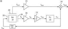
- FIG. 2is a block diagram illustrating a system for sensing angular motion using a MEMS gyroscope, in accordance with some embodiments of the technology described herein.
- FIG. 3Ais a plot illustrating a square wave signal in the absence of noise and a square wave signal in the presence of direct current (DC) noise, in accordance with some embodiments of the technology described herein.
- DCdirect current
- FIG. 3Bis a plot illustrating a square wave signal in the absence of noise and a square wave signal in the presence of low-frequency noise, in accordance with some embodiments of the technology described herein.
- FIG. 4is a schematic of a phase locked loop (PLL) that may be used with the system of FIG. 2 , in accordance with some embodiments of the technology described herein.
- PLLphase locked loop
- FIG. 5Ais a plot illustrating the output of the PLL of FIG. 4 in the presence of DC noise, in accordance with some embodiments of the technology described herein.
- FIG. 5Bis a plot illustrating the output of the PLL of FIG. 4 in the presence of low-frequency noise, in accordance with some embodiments of the technology described herein.
- FIG. 6is a flowchart of an illustrating process for sensing angular motion using a MEMS gyroscope, in accordance with some embodiments of the technology described herein.
- low-frequency noisecan adversely impact the accuracy of MEMS gyroscope-based systems for sensing angular motion.
- Low-frequency noisecauses a MEMS gyroscope's accuracy to degrade over time (“drift” as it is sometimes termed), which may lead to sensing error to increase at a rate that, in some instances, is as high as 2.5 degrees per hour.
- driftthe accuracy of the MEMS gyroscope can quickly fall below acceptable values.
- a computer-based navigation systemthat relies on a set of MEMS gyroscopes to track the motion of a vehicle. Even if the information output by the MEMS gyroscopes initially accurately reflects the motion of the vehicle, the accuracy of the underlying MEMS gyroscopes will degrade rapidly over time, rendering their output unusable for navigation purposes.
- the inventorshave recognized that low-frequency noise degrades the accuracy of angular motion detection because it causes the duty cycle of the signal used for the demodulation of the sense signal to vary over time—this phenomenon is sometimes called duty cycle jitter.
- the output signalhas a modulation carrier oscillating at the gyroscope's resonance frequency.
- the sense signalis demodulated to baseband before being digitized. Signals oscillating at the gyroscope's resonance frequency are used to demodulate the sense signal to baseband.
- the duty cycle of the demodulating signalvaries over time due to low-frequency noise, the signal resulting from the demodulation is distorted such that it may not accurately reflect the angular motion experienced by the gyroscope.
- duty cycle jittermay be limited by forcing the duty cycle of the demodulating signal to be approximately 50% (or a different target value). This may be achieved, in some embodiments, by controlling, based on a control signal, the frequency output by a phase locked loop (PLL).
- PLLphase locked loop
- the control signalmay be generated based on: 1) a first signal generated based on a rising edge of the resonator signal and a rising edge of a reference signal, and 2) a second signal generated based on a falling edge of the resonator signal and a falling edge of the reference signal.
- Generating the control signal based on 1) and 2)may set the duty cycle of the demodulating signal to be approximately 50% (or to any other suitable percentage threshold set a priori) while maintaining the frequency of the demodulating signal at the resonant frequency of the gyroscope.
- the control signalmay result in the demodulating signal experiencing undesirable frequency fluctuations.
- Such fluctuationsmay originate due to the presence of ripples or other undesired features in the amplitude of the control signal when generated based on 1) and 2).
- Distortions in the detection of angular motionmay arise when a demodulating signal exhibiting such frequency fluctuations is mixed with the sense signal.
- such undesired fluctuations in the frequency of the demodulating signalmay be reduced or entirely removed by preventing the formation of undesired ripples that may otherwise arise in the control signal.
- the PLLmay lock to the desired frequency without experiencing undesired fluctuations.
- the formation of ripples in the control signalmay be prevented by generating the control signal not only based on 1) and 2), but also based on 3) an enabling signal.
- the enabling signalmay be timed and arranged to block the ripples from the PLL. In this way, fluctuations in the frequency of the demodulating signal are limited.
- the bias instability of systems designed in this mannercan be limited to less than 1 degree per hour, in some circumstances.
- FIG. 1is a block diagram illustrating a gyroscope 10 , according to some embodiments.
- Gyroscope 10comprises resonator 12 and sensor 14 .
- Resonator 12is configured to resonate periodically, when driven by a drive signal.
- Sensor 14(which may be an accelerometer in some embodiments) is configured to sense angular velocities. Accordingly, when gyroscope 10 is subjected to angular motion (e.g., when the gyroscope is rotated relative to an axis), the angular rate at which the angular motion occurs (e.g., the rate of rotation) can be sensed using sensor 14 .
- gyroscope 10is configured to sense angular velocities by detecting acceleration arising from the Coriolis effect.
- the Coriolis effectarises when: 1) resonator 12 resonates; and 2) the gyroscope is subjected to angular motion.
- sensor 14may detect the acceleration resulting from the Coriolis effect.
- the angular rate associated with the angular motionmay be inferred from the acceleration, for example, by using sense circuitry coupled to sensor 14 .
- gyroscope 10is illustrated in FIG. 1B , in accordance with some embodiments.
- gyroscope 100is configured to resonate in a direction parallel to the x-axis and to detect Coriolis forces in a direction parallel to the y-axis. It should be appreciated, however, that gyroscopes of the types described herein are not limited to any specific direction of resonance or detection.
- MEMS gyroscope 100includes proof masses 101 and 102 , anchors 103 , fingers 105 , 107 , 114 , 132 and 133 , and stationary electrodes 104 , 108 , 110 , 122 and 123 .
- Proof masses 101 and 102may be suspended above substrate 115 , which may be made of silicon in some embodiments.
- Substrate 115 , proof masses 101 and 102 , anchors 103 , fingers 105 , 107 , 114 , 132 and 133 , and stationary electrodes 104 , 108 , 110 , 122 and 123may be fabricated using MEMS techniques.
- proof masses 101 and 102may be formed by depositing a layer of material on top of a sacrificial layer. Subsequently, the sacrificial layer may be etched, thus leaving the proof masses suspended above the substrate 115 .
- proof masses 101 and 102are made of polysilicon (doped or undoped). Proof masses 102 sand 101 may serve as resonator 12 and sensor 14 (see FIG. 1A ), respectively.
- Proof mass 101is connected to the substrate via anchors 103 , which may extend in a direction parallel to the z-axis.
- proof mass 101is connected to the anchors via flexures 111 . Flexures 111 may allow for motion of proof mass 101 in a direction parallel to the y-axis.
- proof mass 102is enclosed within proof mass 101 in the xy-plane.
- Proof mass 101 and 102are elastically coupled to one another via flexures 117 . Flexures 117 allow for motion of proof mass 102 in a direction parallel to the x-axis.
- Operation of the MEMS gyroscope 100is based on the Coriolis effect.
- angular motion of the MEMS gyroscope about the z-axismay be detected by detecting acceleration of the proof mass 101 in the y-axis direction when proof mass 102 is driven to oscillate in the x-axis direction.
- MEMS gyroscopes of the types described hereinare not limited to detection of angular motion about the z-axis as shown in the figure, but can be used to detect motion about any suitable axis. Additionally, some MEMS gyroscopes may even be configured as multi-axis gyroscopes, whereby angular motion about two or three axes may be detected using a single device (e.g., a single pair of elastically coupled proof masses).
- Oscillation of proof mass in the x-axis directionmay be initiated using drivers 106 and 109 (though any other suitable number of drivers may be used).
- Driver 106includes stationary electrodes 104 and fingers 105 .
- Stationary electrodes 104may be attached to substrate 115 via anchors extending along the z-axis.
- Fingers 105are connected to, and extend away from, proof mass 102 .
- Fingers 105 and stationary electrodes 104are arranged in an alternating configuration and form a plurality of capacitors.
- driver 109includes stationary electrodes 108 and fingers 107 . Motion of the proof mass 102 along the x-axis may be instituted through the application of a signal at the capacitors formed between the stationary electrodes and the fingers.
- Motion of the proof mass 102may be monitored using motion detector 151 .
- Motion detector 151includes stationary electrodes 110 and fingers 114 forming a plurality of capacitors. For the sake of simplicity, only one motion detector 151 is shown in the exemplary embodiment of FIG. 1B , although alternative embodiments may have additional motion detectors.
- the extent to which finger 114 and stationary electrode 110 overlap with one anotheris varied (due to a longitudinal motion of the finger), thus varying the capacitance of the capacitor.
- a signalmay be generated in the motion detector 151 in response to motion of proof mass 102 .
- motion of the proof mass 102may give rise to an electric current in the capacitors of motion detector 151 , and the amplitude of the electric current is proportional to the instantaneous velocity of the proof mass.
- proof mass 101may be used to sense these accelerations.
- motion detector 112which includes stationary electrodes 122 and fingers 132
- motion detector 113which includes stationary electrodes 123 and fingers 133
- motion detector 112which includes stationary electrodes 122 and fingers 132
- motion detector 113which includes stationary electrodes 123 and fingers 133
- motion of the proof mass 101 in the y-axis directionmay generate an electric current in the capacitors of the motion detectors 112 and 113 .
- the magnitude of the acceleration experienced by the proof mass 101and as a result the angular velocity of MEMS gyroscope 100 , may be inferred from the electric current generated by the motion detectors 112 and 113 .
- Control of the operations of MEMS gyroscope 10is performed using control circuitry, which may be integrated in the same substrate as the gyroscope or in a separate substrate.
- the control circuitrymay include circuits for causing resonator 12 to oscillate, circuits for monitoring motion of resonator 12 , circuits for sensing motion of sensor 14 , and/or circuits for stabilizing the motion of sensor 14 .
- System 200includes MEMS gyroscope (“gyro”) 201 , which may serve as MEMS gyroscope 10 (an example of which is illustrated in FIG. 1B ), amplifiers 208 and 216 , comparator 210 , phase locked loop (“PLL”) 212 , driver 214 and mixer 218 .
- MEMS gyroscope(“gyro”) 201 , which may serve as MEMS gyroscope 10 (an example of which is illustrated in FIG. 1B ), amplifiers 208 and 216 , comparator 210 , phase locked loop (“PLL”) 212 , driver 214 and mixer 218 .
- PLLphase locked loop
- Gyro 201includes terminals 202 , 204 and 206 .
- Terminal 202also referred to as the “resonator path input terminal,” is coupled to driver 214 .
- Signal S drivemay be configured to cause, when received at terminal 202 , resonance of the resonator of gyro 201 .
- S drivemay be a voltage signal or a current signal.
- Terminal 202may be an electrode arranged for driving the gyro's resonator, examples of which include a stationary electrode 104 and a finger 105 (see FIG. 1B ).
- Driver 214may include circuitry for causing gyro 201 's resonator to resonate.
- driver 214may include an amplifier and/or circuitry for driving gyro 201 's resonator at its resonant frequency.
- signal V PLLprovided by PLL 212 , may provide an indication regarding the resonant frequency of gyro 201 's resonator.
- driver 214may drive gyro 201 's resonator at the resonant frequency based on the information received via V PLL .
- Terminal 204also referred to as the “sense path output terminal,” is coupled to amplifier 216 .
- Terminal 204may output a signal that is representative of the angular velocity sensed by gyro's 201 sensor.
- Terminal 204may be an electrode arranged for providing a signal indicative of motion of gyro 201 in response to Coriolis forces, examples of which being a stationary electrode 122 and a finger 132 (see FIG. 1B ).
- motion of gyro 201 in response to a Coriolis forcemay cause a variation in the capacitance of a sense capacitor (e.g., motion detector 112 ).
- amplifier 216is configured to generate, based on S sense1 , a voltage V sense1 that is representative of the Coriolis force experienced by gyro 201 .
- amplifier 216may include a trans-impedance amplifier and/or a capacitance-to-voltage converter.
- Terminal 206is coupled to amplifier 208 .
- the signal at terminal 206may be used to monitor motion of gyro 201 's resonator, for example to determine whether the resonator is oscillating at its resonant frequency or not.
- Terminal 206may be an electrode arranged for providing a signal indicative of the motion of gyro 201 's resonator, examples of which being a stationary electrode 110 and a finger 114 (see FIG. 1B ).
- motion of gyro 201 's resonator in response to signal S drivemay cause a variation in the capacitance of a capacitor (e.g., motion detector 151 ).
- the signal representing the variation in the capacitance of such capacitoris indicated in FIG. 2 as S res .
- amplifier 208is configured to generate, based on S res , a voltage V res that is representative of the motion of gyro 201 's resonator.
- amplifier 208may include a trans-impedance amplifier and/or a capacitance-to-voltage converter.
- Comparator 210may be configured to convert the signal output by amplifier 208 into a square wave.
- comparator 210may receive V res as a first input, a reference voltage as a second input, and may output a value depending on whether V res is greater or less than the reference voltage. For example, if V res is greater than the reference voltage, V comp may be equal to a voltage representing a logic 1 and if V res is less than the reference voltage, V comp may be equal to a voltage representing a logic 0. The opposite logic is also possible.
- V resmay include a portion of a sinusoidal signal with no offset (with a zero average value), and the reference voltage may be set to zero.
- V compmay be a square wave with a 50% duty cycle.
- V compThe output of comparator 210 , V comp , may be provided as input to PLL 212 , which in response may output signal V PLL .
- PLL 212may be configured to lock the frequency of V PLL to the resonant frequency of gyro 201 's resonator.
- V PLLalso referred to as the “demodulating signal,” may be used to demodulate signal V sense1 to baseband.
- V PLLmay be mixed with (e.g., multiplied to) sense signal V sense1 using mixer 218 .
- the signal resulting from the mixing—V sense2may provide an indication as to the angular motion experienced by gyroscope 201 .
- signal V PLLmay be provided as input to driver 214 to ensure that gyro 201 's resonator is driven at its resonant frequency.
- system 200may experience low-frequency noise.
- noisemay originate, among other components, at amplifier 208 and comparator 210 and may be due, in part or in full, to impurities in the conductive channel of a transistor or generation and recombination noise of a transistor due to base current, among other possible effects.
- the signal V compmay be a square wave with a 50% duty cycle when V res is a sinusoidal with a zero offset.
- low-frequency noisemay be additively combined to V res .
- V resmay exhibit a non-zero offset (a non-zero average value).
- FIG. 3AThis scenario is illustrated in FIG. 3A , in accordance with some embodiments.
- the top portion of FIG. 3Aillustrates V res , which includes a portion of a sinusoidal signal.
- Two axesare illustrated, 300 and 302 .
- Axis 300represents the time axis when V res includes no offset. In this case, V res exhibits a substantially zero average.
- Axis 302represents the time axis when V res includes a constant offset, which may be due to the presence of direct current (DC) noise (a constant additive noise).
- DCdirect current
- the average of V resis vertically offset relative to the time axis. In other words, V res exhibits a non-zero average.
- V comp(no offset)
- V compexhibits a transition (rising edge or falling edge) in response to V res crossing axis 300 .
- V resrises above axis 300 and as a result V comp exhibits a rising edge.
- V compfalls below axis 300 and as a result V comp exhibits a falling edge.
- V comphas a 50% duty cycle.
- low-frequency noise with a bandwidth greater than zeromay be combined additively with V res .
- the low-frequency noise described hereinmay exhibit a spectral bandwidth of less than 10 KHz, less than 7.5 KHz, less than 5 KHz, less than 2.5 KHz, less than 1 KHz, less than 750 Hz, less than 500 Hz, less than 250 Hz, or less than 100 Hz, among other possible values.
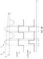
- FIG. 3Bis a plot illustrating V comp in the presence of low-frequency noise with a bandwidth greater than zero, in accordance with some embodiments.
- axis 300represents the time axis when V res includes no offset. In this case, V res exhibits a substantially zero average.
- Axis 304represents the time axis in the presence of a low-frequency noise.
- the offset of V resis not only different from zero, but it also varies over time. This is because, having a bandwidth that is greater than zero, the noise that is added to V res has time-varying amplitude.
- V comp(no offset)
- V comp(with varying offset)” illustrates V comp in the presence of low-frequency noise with a bandwidth greater than zero, assuming that the reference voltage of comparator 210 is set to zero.
- a demodulating signalmay be generated to have a duty cycle substantially equal to 50% even in the presence of low-frequency noise.
- a representative PLL configured to produce such a demodulating signalis illustrated in FIG. 4 , in accordance with some embodiments.
- PLL 412may serve as PLL 212 .
- PLL 412includes dual-edge phase frequency detector (DE-PFD) 402 , current generators I 1 and I 2 , switches S 1 , S 2 and S 3 , voltage controlled oscillator (VCO) 404 , frequency divider 406 , capacitor C 0 and C 1 and resistor R 1 .
- Current generators I 1 and I 2 , switches S 1 , S 2 and capacitor C 0may be collectively arranged to serve as a charge pump, as will be described further below.
- FIG. 5Ais a plot illustrating an example of how PLL 412 may be configured to operate in the presence of DC noise, in accordance with some embodiments.
- V squaredrepresents the signal output by frequency divider 406 .
- V squaredmay have a frequency that is a fraction of the frequency of V PLL . The fraction may be determined by the dividing factor of frequency divider 406 .
- DE-PFD 402may be configured to receive as inputs V comp and V squared , and to compare the times at which these input signals exhibit an edge. The output signals, V up and V down , may be generated based on the comparison. For example, DE-PFD 402 may generate V up to have a pulse having a width substantially equal to the interval between the occurrence of a falling edge in V comp and the occurrence of a falling edge in V squared . Additionally, DE-PFD 402 may generate V down to have a pulse having a width substantially equal to the interval between the occurrence of a rising edge in V comp and the occurrence of a rising edge in V squared . In this way, V up and V down provide a measure of the extent to which V comp deviates from the 50% duty cycle scenario.
- V upmay be used to enable switch S 1 and V down to enable switch S 2 .
- switch S 1when V up exhibits a pulse, switch S 1 may be in a conductive state, and when V down exhibits a pulse, switch S 2 may be in a conductive state.
- switch S 1When switch S 1 is in a conductive state (e.g., closed) and switch S 2 in a non-conductive state (e.g., open), current I 1 charges capacitor C 0 , thus increasing voltage V cap .
- switch S 1is in a non-conductive state and switch S 2 in a conductive state, current I 2 discharges capacitor C 0 , thus decreasing voltage V cap .
- V capdecreases from V 1 to V r in response to the V down -pulse and increases from V r to V 1 in response to the V up -pulse.
- V capwas provided as input to VCO 404 to control the frequency of V PLL
- Such a frequency shift in V PLLmay distort the demodulation of V sense1 , thus causing sensing errors.
- the ripples arising in V capmay be blocked from VCO 404 .
- Switch S 3may be used to block the ripples, in some embodiments.
- switch S 3may be configured to be in a non-conductive state when V cap exhibits a ripple, and in a conductive state during an interval outside the ripples.
- V enablemay be timed and arranged to prevent the ripples from reaching VCO 404 .
- V enablemay be generated by control circuitry (not illustrated in FIG. 4 ) coupled to switch S 3 .
- An example of V enableis shown in FIG. 5A .
- V ctrlV 1 .
- switch S 3is toggled to its non-conductive state, voltage V 1 is maintained at the input of VCO 404 due to the presence of capacitor C 1 .
- V ctrlremains substantially constant and equal to V 1 . Therefore, the frequency of V PLL is not adjusted in the presence of DC noise.
- FIG. 5Bis a plot illustrating an example of how PLL 412 may be operated in the presence of low-frequency noise, in accordance with some embodiments.
- V compexhibits duty cycle jitter.
- the interval (t R4 ⁇ t R3 ) between the occurrence of the first rising edge in V squared and the occurrence of the first rising edge in V compis different than the interval (t F3 ⁇ t F4 ) between the occurrence of the first falling edge in V squared and the occurrence of the first falling edge in V comp .
- the interval (t R4 ⁇ t R3 ) between the occurrence of the first rising edge in V squared and the occurrence of the first rising edge in V compis different than the interval (t R5 ⁇ t R6 ) between the occurrence of the second rising edge in V squared and the occurrence of the second rising edge in V comp .
- the interval (t R5 ⁇ t R5 ) between the occurrence of the second rising edge in V squared and the occurrence of the second rising edge in V compis different than the interval (t F6 ⁇ t F5 ) between the occurrence of the second falling edge in V squared and the occurrence of the second falling edge in V comp .
- the width of the first V up -pulseis different than the width of the second V up -pulse, which is different than the width of the first V down -pulse, which is different than the width of the second V down -pulse.
- switch S 1When V up exhibits a pulse, switch S 1 may be in a conductive state, thus causing current I 1 to charge capacitor C 0 .
- switch S 2When V down exhibits a pulse, switch S 2 may be in a conductive state, thus causing current I 2 to discharge capacitor C 0 .
- voltage V capdecreases from V 1 to V r1 .
- voltage V capincreases from V r1 to V 2 . Because the width of the first V down -pulse is greater than the width of the first V up -pulse, the extent to which V cap increases from V r1 to V 2 is less than the extent to which V cap decreases from V 1 to V r1 .
- V 2is less than V 1 .
- the width of the second V down -pulseis greater than the width of the second V up -pulse, the extent to which V cap increases from V r2 to V 3 is less than the extent to which V cap decreases from V 2 to V r2 .
- V 3is less than V 2 .
- duty cycle jitter caused by low-frequency noiseis counteracted by varying the frequency output by VCO 404 , which is performed by varying the input of VCO 404 from V 1 to V 2 , and from V 2 to V 3 .
- V capexhibits a ripple of amplitude V r1 between t R3 and t F3 and a ripple of amplitude V r2 between t R6 and t F6 .
- the ripplesmay be blocked.
- the ripplesmay be blocked by causing switch S 3 to remain in a non-conductive state when a ripple is present.
- V enablemay be used to control the state of switch S 3 .
- V ctrlvaries from V 1 to V 2 , without exhibiting a ripple.
- switch S 3When switch S 3 is toggled to its non-conductive state, voltage V 2 is maintained at the input of VCO 404 due to the presence of capacitor C 1 .
- V ctrlvaries from V 2 to V 3 , without exhibiting a ripple.
- switch S 3is toggled back to its non-conductive state, voltage V 3 is maintained at the input of VCO 404 due to the presence of capacitor C 1 .
- the voltage provided to VCO 404varies from V 1 to V 2 and then to V 3 , causing the frequency of V PLL to vary from f 1 to f 2 and then to f 3 . Varying the frequency in this manner may ensure than the duty cycle of V PLL remain approximately 50%. It should be appreciated that the techniques described in connection with FIG. 5B may be particularly effective to counteract low frequency noise (e.g., with a spectral bandwidth of less than 10 KHz, less than 7.5 KHz, less than 5 KHz, less than 2.5 KHz, less than 1 KHz, less than 750 Hz, less than 500 Hz, less than 250 Hz, or less than 100 Hz, among other possible values), but may be less effective to counteract noise with higher frequency content.
- low frequency noisee.g., with a spectral bandwidth of less than 10 KHz, less than 7.5 KHz, less than 5 KHz, less than 2.5 KHz, less than 1 KHz, less than 750 Hz, less than 500 Hz, less than 250 Hz,
- Process 600for sensing angular motion using a MEMS gyroscope is illustrated in FIG. 6 , in accordance with some embodiments of the technology described herein.
- process 600may be performed by illustrative system 200 , described in connection with FIG. 2 .
- Process 600begins at act 602 , in which a MEMS gyroscope is driven to resonate.
- gyro 201may be driven to resonate using S drive .
- a resonator signal generated in response to resonance of the MEMS gyroscopemay be received from the resonator path output terminal of the MEMS gyroscope.
- V compmay be received, in response to resonance of gyro 201 , from terminal 206 , and through amplifier 208 and comparator 210 .
- a first sense signal generated in response to a Coriolis forcemay be received from the sense path output terminal of the MEMS gyroscope.
- V sense1may be received from terminal 204 , and through amplifier 216 .
- the Coriolis forcemay arise in response to angular motion in combination with the resonance of the MEMS gyroscope.
- a control signalmay be generated based on: 1) a first signal generated based on a rising edge of the resonator signal and a rising edge of a reference signal; 2) a second signal generated based on a falling edge of the resonator signal and a falling edge of the reference signal; and 3) an enabling signal.
- signal V ctrlmay be generated based on: 1) V down ; 2) V up ; and 3) V enable .
- the enabling signalmay be configured to prevent the formation of ripples in the control signal.
- the enabling signalis configured to control a state of a switch, such as switch S 3 of FIG. 4 .
- the enabling signalmay be configured to maintain the switch in a non-conductive state when a ripple is received at the switch.
- the frequency of a demodulating signalmay be controlled using the control signal.
- the frequency of V PLLmay be controlled using V ctrl .
- the frequency of the demodulating signalmay be varied from f 1 to f 2 in response to the control signal varying from V 1 to V 2 .
- a second sense signalmay be generated using the first sense signal and the demodulating.
- signal V sense2may be generated using signals V sense1 and V PLL .
- the first sense signal and the demodulating signalmay be mixed so that the second sense signal is a demodulated version of the first sense signal.
- a characteristice.g., a magnitude and/or a direction of the angular velocity of the angular motion experienced by the MEMS gyroscope may be determined based on the second sense signal.
- the terms “approximately”, “substantially,” and “about”may be used to mean within ⁇ 20% of a target value in some embodiments, within ⁇ 10% of a target value in some embodiments, within ⁇ 5% of a target value in some embodiments, and within ⁇ 2% of a target value in some embodiments.
- the terms “approximately” and “about”may include the target value.
Landscapes
- Engineering & Computer Science (AREA)
- Physics & Mathematics (AREA)
- General Physics & Mathematics (AREA)
- Radar, Positioning & Navigation (AREA)
- Remote Sensing (AREA)
- Signal Processing (AREA)
- Gyroscopes (AREA)
Abstract
Description
Claims (20)
Priority Applications (3)
| Application Number | Priority Date | Filing Date | Title |
|---|---|---|---|
| US16/042,742US11041722B2 (en) | 2018-07-23 | 2018-07-23 | Systems and methods for sensing angular motion in the presence of low-frequency noise |
| DE202019104047.5UDE202019104047U1 (en) | 2018-07-23 | 2019-07-22 | System for detecting angular movement in the presence of low frequency noise |
| CN201910665997.5ACN110749316B (en) | 2018-07-23 | 2019-07-23 | System and method for sensing angular motion in the presence of low frequency noise |
Applications Claiming Priority (1)
| Application Number | Priority Date | Filing Date | Title |
|---|---|---|---|
| US16/042,742US11041722B2 (en) | 2018-07-23 | 2018-07-23 | Systems and methods for sensing angular motion in the presence of low-frequency noise |
Publications (2)
| Publication Number | Publication Date |
|---|---|
| US20200025566A1 US20200025566A1 (en) | 2020-01-23 |
| US11041722B2true US11041722B2 (en) | 2021-06-22 |
Family
ID=68576629
Family Applications (1)
| Application Number | Title | Priority Date | Filing Date |
|---|---|---|---|
| US16/042,742Active2039-03-21US11041722B2 (en) | 2018-07-23 | 2018-07-23 | Systems and methods for sensing angular motion in the presence of low-frequency noise |
Country Status (3)
| Country | Link |
|---|---|
| US (1) | US11041722B2 (en) |
| CN (1) | CN110749316B (en) |
| DE (1) | DE202019104047U1 (en) |
Citations (77)
| Publication number | Priority date | Publication date | Assignee | Title |
|---|---|---|---|---|
| US5218867A (en) | 1989-07-29 | 1993-06-15 | British Aerospace Public Limited Company | Single axis attitude sensor |
| US5540094A (en) | 1990-12-22 | 1996-07-30 | British Aerospace Public Limited Company | Scale factor compensation for piezo-electric rate sensors |
| US5866816A (en) | 1995-05-30 | 1999-02-02 | Alliedsignal Inc. | Angular rate sensor misalignment correction |
| US5889193A (en) | 1994-12-29 | 1999-03-30 | Robert Bosch Gmbh | Device for ascertaining a rate of rotation |
| US5969225A (en) | 1996-09-25 | 1999-10-19 | Murata Manufacturing Co., Ltd. | Angular-velocity detection apparatus |
| US5987984A (en) | 1997-03-13 | 1999-11-23 | Robert Bosch Gmbh | Device for determining a motion parameter with automatic scaling factor correction |
| US5992233A (en) | 1996-05-31 | 1999-11-30 | The Regents Of The University Of California | Micromachined Z-axis vibratory rate gyroscope |
| US6018996A (en) | 1997-06-06 | 2000-02-01 | Denso Corporation | Vibration type angular velocity detector |
| US6198355B1 (en) | 1998-03-13 | 2001-03-06 | Telefonaktiebolaget Lm Ericsson (Publ) | Dual edge-triggered phase detector and phase locked loop using same |
| US20010029784A1 (en) | 2000-03-17 | 2001-10-18 | Hideya Kurachi | Angular speed sensor device |
| WO2001079862A1 (en) | 2000-04-14 | 2001-10-25 | Microsensors, Inc. | Z-axis micro-gyro |
| US6510737B1 (en) | 2000-09-15 | 2003-01-28 | Bei Technologies, Inc. | Inertial rate sensor and method with improved tuning fork drive |
| US20030101814A1 (en) | 2001-08-17 | 2003-06-05 | Challoner A. Dorian | Microgyroscope with electronic alignment and tuning |
| US6598455B1 (en) | 1999-06-30 | 2003-07-29 | California Institute Of Technology | Non-inertial calibration of vibratory gyroscopes |
| US6768358B2 (en) | 2001-08-29 | 2004-07-27 | Analog Devices, Inc. | Phase locked loop fast power up methods and apparatus |
| US6934665B2 (en) | 2003-10-22 | 2005-08-23 | Motorola, Inc. | Electronic sensor with signal conditioning |
| US20050183502A1 (en) | 2004-02-23 | 2005-08-25 | Halliburton Energy Services, Inc. | Motion-responsive coupled masses |
| US20050257596A1 (en) | 2002-11-20 | 2005-11-24 | Fell Christopher P | Method and apparatus for measuring scalefactor variation in a vibrating structure gyroscope |
| US20060142958A1 (en) | 2003-06-30 | 2006-06-29 | Heinz-Werner Morell | Method for monitoring a vibrating gyroscope |
| US20060201250A1 (en) | 2005-03-10 | 2006-09-14 | Kourepenis Anthony S | Force compensated comb drive |
| US7123111B2 (en) | 2002-03-20 | 2006-10-17 | Qinetiq Limited | Micro-electromechanical systems |
| US7188522B2 (en) | 2003-07-04 | 2007-03-13 | Siemens Aktiengesellschaft | Method for aligning a rotation rate sensor |
| US20070119258A1 (en) | 2005-11-15 | 2007-05-31 | California Institute Of Technology | Resonant vibratory device having high quality factor and methods of fabricating same |
| US20070163345A1 (en) | 2004-02-18 | 2007-07-19 | Toshiyuki Nozoe | Angular velocity sensor |
| US7253615B2 (en) | 2004-05-05 | 2007-08-07 | General Electric Company | Microelectromechanical system sensor and method for using |
| US20070256495A1 (en) | 2006-04-18 | 2007-11-08 | Watson William S | Vibrating Inertial Rate Sensor Utilizing Split or Skewed Operational Elements |
| US20080170742A1 (en) | 2007-01-17 | 2008-07-17 | The Regents Of The University Of California | Apparatus and method using capacitive detection with inherent self-calibration |
| US20080204093A1 (en)* | 2007-02-28 | 2008-08-28 | Micron Technology, Inc | Multiphase generator with duty-cycle correction using dual-edge phase detection and method for generating a multiphase signal |
| US20090083011A1 (en) | 2007-08-07 | 2009-03-26 | Zhili Hao | Predictive system and method for the design of mechanical resonant devices |
| US20090249875A1 (en) | 2005-07-26 | 2009-10-08 | Robert Bosch Gmbh | Rate-of-turn sensor |
| US20090272189A1 (en) | 2006-01-25 | 2009-11-05 | The Regents Of The University Of California | Robust Six Degree-of-Freedom Micromachined Gyroscope with Anti-Phase Drive Scheme and Mehtod of Operation of the Same |
| US20090282916A1 (en) | 2008-05-16 | 2009-11-19 | Rosemount Aerospace Inc. | System and Method for Providing High-Range Capability with Closed-Loop Inertial Sensors |
| US7640803B1 (en) | 2004-05-26 | 2010-01-05 | Siimpel Corporation | Micro-electromechanical system inertial sensor |
| EP2211458A1 (en) | 2009-01-27 | 2010-07-28 | Freescale Semiconductor, Inc. | Charge amplifier with DC feedback sampling |
| US20100212424A1 (en) | 2007-09-18 | 2010-08-26 | Atlantic Inertial Systems Limited | Improvements in or relating to angular velocity sensors |
| US20100271067A1 (en) | 2009-04-28 | 2010-10-28 | Stmicroelectronics S.R.L. | Digital noise protection circuit and method |
| US20110167891A1 (en) | 2009-10-20 | 2011-07-14 | Analog Devices, Inc. | Apparatus and Method for Calibrating MEMS Inertial Sensors |
| US7980133B2 (en) | 2008-08-19 | 2011-07-19 | Analog Devices, Inc. | Method and apparatus for a micromachined multisensor |
| US20110179872A1 (en) | 2009-01-22 | 2011-07-28 | Panasonic Corporation | Drive circuit and physical quantity sensor device |
| US20120006114A1 (en) | 2007-02-13 | 2012-01-12 | Stmicroelectronics S.R.L. | Microelectromechanical gyroscope with open loop reading device and control method |
| US20120024057A1 (en) | 2009-03-10 | 2012-02-02 | Panasonic Crporation | Angular velocity sensor |
| US8151641B2 (en) | 2009-05-21 | 2012-04-10 | Analog Devices, Inc. | Mode-matching apparatus and method for micromachined inertial sensors |
| CN102620726A (en) | 2012-04-04 | 2012-08-01 | 西北工业大学 | Double-closed-loop control circuit of micromechanical gyroscope |
| US8375789B2 (en) | 2009-06-03 | 2013-02-19 | Stmicroelectronics S.R.L. | Microelectromechanical gyroscope with position control driving and method for controlling a microelectromechanical gyroscope |
| US8401140B2 (en) | 2008-09-05 | 2013-03-19 | Freescale Semiconductor, Inc. | Phase/frequency detector for a phase-locked loop that samples on both rising and falling edges of a reference signal |
| US20130098153A1 (en) | 2011-10-21 | 2013-04-25 | The Regents Of The University Of California | High range digital angular rate sensor based on frequency modulation |
| US20130099836A1 (en)* | 2011-10-25 | 2013-04-25 | Invensense, Inc. | Gyroscope with phase and duty-cycle locked loop |
| US8446222B2 (en) | 2008-07-08 | 2013-05-21 | Sand 9, Inc. | Apparatus and methods for reducing noise in oscillating signals |
| JP2013521486A (en) | 2010-03-03 | 2013-06-10 | シリコン、センシング、システムズ、リミテッド | sensor |
| US8464571B1 (en) | 2009-03-20 | 2013-06-18 | Analog Devices, Inc. | Systems and methods for determining resonant frequency and quality factor of overdamped systems |
| US8497746B2 (en) | 2009-06-05 | 2013-07-30 | Stmicroelectronics S.R.L. | Switched-capacitor band-pass filter of a discrete-time type, in particular for cancelling offset and low-frequency noise of switched-capacitor stages |
| EP2657648A2 (en) | 2012-04-26 | 2013-10-30 | Analog Devices, Inc. | MEMS Gyroscopes with Reduced Errors |
| US20140000365A1 (en) | 2012-06-29 | 2014-01-02 | Murata Electronics Oy | Vibratory gyroscope |
| US20140000366A1 (en) | 2012-06-29 | 2014-01-02 | Murata Electronics Oy | Vibratory gyroscope |
| US8624679B2 (en) | 2010-04-14 | 2014-01-07 | Analog Devices, Inc. | Method and apparatus for MEMS phase locked loop |
| US8661898B2 (en) | 2008-10-14 | 2014-03-04 | Watson Industries, Inc. | Vibrating structural gyroscope with quadrature control |
| US20140085017A1 (en) | 2012-09-24 | 2014-03-27 | Invensense, Inc. | Mems device oscillator loop with amplitude control |
| US8689631B1 (en) | 2011-06-23 | 2014-04-08 | The United States Of America As Represented By Secretary Of The Navy | High sensitivity mechanical gyro with reduced quadrature error |
| US9103845B2 (en) | 2013-03-08 | 2015-08-11 | Freescale Semiconductor Inc. | System and method for reducing offset variation in multifunction sensor devices |
| US20150226557A1 (en) | 2014-02-12 | 2015-08-13 | Murata Manufacturing Co., Ltd. | Drive circuit for mems resonator startup |
| US20150247877A1 (en) | 2014-02-28 | 2015-09-03 | Seiko Epson Corporation | Electronic device, electronic apparatus, and moving object |
| US20150285658A1 (en) | 2014-02-24 | 2015-10-08 | The Regents Of The University Of California | Utilization of Mechanical Quadrature in Silicon MEMS Vibratory Gyroscope to Increase and Expand the Long Term In-Run Bias Stability |
| US9176165B2 (en) | 2011-07-08 | 2015-11-03 | Thales | Vibrating micro-system with automatic gain control loop, with integrated control of the quality factor |
| US20150341041A1 (en) | 2014-05-21 | 2015-11-26 | Robert Bosch Gmbh | Phase Lock Loop Circuit Having a Wide Bandwidth |
| US9278847B2 (en) | 2008-12-23 | 2016-03-08 | Stmicroelectronics S.R.L. | Microelectromechanical gyroscope with enhanced rejection of acceleration noises |
| US9410806B2 (en) | 2013-08-26 | 2016-08-09 | Robert Bosch Gmbh | System and method for gyroscope zero-rate-offset drift reduction through demodulation phase error correction |
| US9459100B2 (en) | 2014-05-21 | 2016-10-04 | Robert Bosch Gmbh | Stepped sinusoidal drive for vibratory gyroscopes |
| US20160298963A1 (en)* | 2015-04-07 | 2016-10-13 | Analog Devices, Inc. | Quality Factor Estimation for Resonators |
| US20160298965A1 (en) | 2015-04-07 | 2016-10-13 | Analog Devices, Inc. | System, Apparatus, and Method for Resonator and Coriolis Axis Control in Vibratory Gyroscopes |
| US20160334213A1 (en) | 2015-05-13 | 2016-11-17 | Kionix, Inc | Phase-based Measurement and control of a Gyroscope |
| US9506757B2 (en) | 2013-03-14 | 2016-11-29 | Invensense, Inc. | Duty-cycled gyroscope |
| US9634678B1 (en) | 2016-02-25 | 2017-04-25 | Silicon Laboratories Inc. | Feedback control system with rising and falling edge detection and correction |
| US20170135600A1 (en) | 2015-11-16 | 2017-05-18 | Jun-Chau Chien | Gigahertz frequency fringing near-field cardiovascular sensor |
| US20170214407A1 (en) | 2016-01-25 | 2017-07-27 | Nxp B.V. | Phase locked loop circuits |
| US20170307374A1 (en) | 2016-04-20 | 2017-10-26 | Invensense, Inc. | Compensating circuit for a microelectromechanical (mems) resonator |
| CN107449414A (en) | 2016-05-26 | 2017-12-08 | 中国科学院微电子研究所 | Closed-loop phase-locked driving circuit of MEMS gyroscope |
| US20180175840A1 (en)* | 2016-12-19 | 2018-06-21 | Seiko Epson Corporation | Delay circuit, count value generation circuit, and physical quantity sensor |
- 2018
- 2018-07-23USUS16/042,742patent/US11041722B2/enactiveActive
- 2019
- 2019-07-22DEDE202019104047.5Upatent/DE202019104047U1/enactiveActive
- 2019-07-23CNCN201910665997.5Apatent/CN110749316B/enactiveActive
Patent Citations (86)
| Publication number | Priority date | Publication date | Assignee | Title |
|---|---|---|---|---|
| US5218867A (en) | 1989-07-29 | 1993-06-15 | British Aerospace Public Limited Company | Single axis attitude sensor |
| US5540094A (en) | 1990-12-22 | 1996-07-30 | British Aerospace Public Limited Company | Scale factor compensation for piezo-electric rate sensors |
| US5889193A (en) | 1994-12-29 | 1999-03-30 | Robert Bosch Gmbh | Device for ascertaining a rate of rotation |
| US5866816A (en) | 1995-05-30 | 1999-02-02 | Alliedsignal Inc. | Angular rate sensor misalignment correction |
| US5992233A (en) | 1996-05-31 | 1999-11-30 | The Regents Of The University Of California | Micromachined Z-axis vibratory rate gyroscope |
| US5969225A (en) | 1996-09-25 | 1999-10-19 | Murata Manufacturing Co., Ltd. | Angular-velocity detection apparatus |
| US5987984A (en) | 1997-03-13 | 1999-11-23 | Robert Bosch Gmbh | Device for determining a motion parameter with automatic scaling factor correction |
| US6018996A (en) | 1997-06-06 | 2000-02-01 | Denso Corporation | Vibration type angular velocity detector |
| US6198355B1 (en) | 1998-03-13 | 2001-03-06 | Telefonaktiebolaget Lm Ericsson (Publ) | Dual edge-triggered phase detector and phase locked loop using same |
| US6598455B1 (en) | 1999-06-30 | 2003-07-29 | California Institute Of Technology | Non-inertial calibration of vibratory gyroscopes |
| US20010029784A1 (en) | 2000-03-17 | 2001-10-18 | Hideya Kurachi | Angular speed sensor device |
| WO2001079862A1 (en) | 2000-04-14 | 2001-10-25 | Microsensors, Inc. | Z-axis micro-gyro |
| US6510737B1 (en) | 2000-09-15 | 2003-01-28 | Bei Technologies, Inc. | Inertial rate sensor and method with improved tuning fork drive |
| US20030101814A1 (en) | 2001-08-17 | 2003-06-05 | Challoner A. Dorian | Microgyroscope with electronic alignment and tuning |
| US6768358B2 (en) | 2001-08-29 | 2004-07-27 | Analog Devices, Inc. | Phase locked loop fast power up methods and apparatus |
| US7123111B2 (en) | 2002-03-20 | 2006-10-17 | Qinetiq Limited | Micro-electromechanical systems |
| US7219529B2 (en) | 2002-11-20 | 2007-05-22 | Bae Systems Plc | Method and apparatus for measuring scalefactor variation in a vibrating structure gyroscope |
| US20050257596A1 (en) | 2002-11-20 | 2005-11-24 | Fell Christopher P | Method and apparatus for measuring scalefactor variation in a vibrating structure gyroscope |
| US20060142958A1 (en) | 2003-06-30 | 2006-06-29 | Heinz-Werner Morell | Method for monitoring a vibrating gyroscope |
| US7188522B2 (en) | 2003-07-04 | 2007-03-13 | Siemens Aktiengesellschaft | Method for aligning a rotation rate sensor |
| US6934665B2 (en) | 2003-10-22 | 2005-08-23 | Motorola, Inc. | Electronic sensor with signal conditioning |
| US20070163345A1 (en) | 2004-02-18 | 2007-07-19 | Toshiyuki Nozoe | Angular velocity sensor |
| US20050183502A1 (en) | 2004-02-23 | 2005-08-25 | Halliburton Energy Services, Inc. | Motion-responsive coupled masses |
| US7253615B2 (en) | 2004-05-05 | 2007-08-07 | General Electric Company | Microelectromechanical system sensor and method for using |
| US7640803B1 (en) | 2004-05-26 | 2010-01-05 | Siimpel Corporation | Micro-electromechanical system inertial sensor |
| US20060201250A1 (en) | 2005-03-10 | 2006-09-14 | Kourepenis Anthony S | Force compensated comb drive |
| US20090249875A1 (en) | 2005-07-26 | 2009-10-08 | Robert Bosch Gmbh | Rate-of-turn sensor |
| US20070119258A1 (en) | 2005-11-15 | 2007-05-31 | California Institute Of Technology | Resonant vibratory device having high quality factor and methods of fabricating same |
| US20090272189A1 (en) | 2006-01-25 | 2009-11-05 | The Regents Of The University Of California | Robust Six Degree-of-Freedom Micromachined Gyroscope with Anti-Phase Drive Scheme and Mehtod of Operation of the Same |
| US20070256495A1 (en) | 2006-04-18 | 2007-11-08 | Watson William S | Vibrating Inertial Rate Sensor Utilizing Split or Skewed Operational Elements |
| US20080170742A1 (en) | 2007-01-17 | 2008-07-17 | The Regents Of The University Of California | Apparatus and method using capacitive detection with inherent self-calibration |
| US20120006114A1 (en) | 2007-02-13 | 2012-01-12 | Stmicroelectronics S.R.L. | Microelectromechanical gyroscope with open loop reading device and control method |
| US20080204093A1 (en)* | 2007-02-28 | 2008-08-28 | Micron Technology, Inc | Multiphase generator with duty-cycle correction using dual-edge phase detection and method for generating a multiphase signal |
| US20090083011A1 (en) | 2007-08-07 | 2009-03-26 | Zhili Hao | Predictive system and method for the design of mechanical resonant devices |
| US20100212424A1 (en) | 2007-09-18 | 2010-08-26 | Atlantic Inertial Systems Limited | Improvements in or relating to angular velocity sensors |
| US8347718B2 (en) | 2007-09-18 | 2013-01-08 | Atlantic Inertial Systems Limited | Angular velocity sensors |
| US20090282916A1 (en) | 2008-05-16 | 2009-11-19 | Rosemount Aerospace Inc. | System and Method for Providing High-Range Capability with Closed-Loop Inertial Sensors |
| US8446222B2 (en) | 2008-07-08 | 2013-05-21 | Sand 9, Inc. | Apparatus and methods for reducing noise in oscillating signals |
| US7980133B2 (en) | 2008-08-19 | 2011-07-19 | Analog Devices, Inc. | Method and apparatus for a micromachined multisensor |
| US8401140B2 (en) | 2008-09-05 | 2013-03-19 | Freescale Semiconductor, Inc. | Phase/frequency detector for a phase-locked loop that samples on both rising and falling edges of a reference signal |
| US8661898B2 (en) | 2008-10-14 | 2014-03-04 | Watson Industries, Inc. | Vibrating structural gyroscope with quadrature control |
| US9278847B2 (en) | 2008-12-23 | 2016-03-08 | Stmicroelectronics S.R.L. | Microelectromechanical gyroscope with enhanced rejection of acceleration noises |
| US20110179872A1 (en) | 2009-01-22 | 2011-07-28 | Panasonic Corporation | Drive circuit and physical quantity sensor device |
| EP2211458A1 (en) | 2009-01-27 | 2010-07-28 | Freescale Semiconductor, Inc. | Charge amplifier with DC feedback sampling |
| US20120024057A1 (en) | 2009-03-10 | 2012-02-02 | Panasonic Crporation | Angular velocity sensor |
| US8464571B1 (en) | 2009-03-20 | 2013-06-18 | Analog Devices, Inc. | Systems and methods for determining resonant frequency and quality factor of overdamped systems |
| US20100271067A1 (en) | 2009-04-28 | 2010-10-28 | Stmicroelectronics S.R.L. | Digital noise protection circuit and method |
| US8151641B2 (en) | 2009-05-21 | 2012-04-10 | Analog Devices, Inc. | Mode-matching apparatus and method for micromachined inertial sensors |
| US8616055B2 (en) | 2009-05-21 | 2013-12-31 | Analog Devices, Inc. | Mode-matching apparatus and method for micromachined inertial sensors |
| US8375789B2 (en) | 2009-06-03 | 2013-02-19 | Stmicroelectronics S.R.L. | Microelectromechanical gyroscope with position control driving and method for controlling a microelectromechanical gyroscope |
| US8497746B2 (en) | 2009-06-05 | 2013-07-30 | Stmicroelectronics S.R.L. | Switched-capacitor band-pass filter of a discrete-time type, in particular for cancelling offset and low-frequency noise of switched-capacitor stages |
| US20110167891A1 (en) | 2009-10-20 | 2011-07-14 | Analog Devices, Inc. | Apparatus and Method for Calibrating MEMS Inertial Sensors |
| US8701459B2 (en) | 2009-10-20 | 2014-04-22 | Analog Devices, Inc. | Apparatus and method for calibrating MEMS inertial sensors |
| JP2013521486A (en) | 2010-03-03 | 2013-06-10 | シリコン、センシング、システムズ、リミテッド | sensor |
| US8624679B2 (en) | 2010-04-14 | 2014-01-07 | Analog Devices, Inc. | Method and apparatus for MEMS phase locked loop |
| US8689631B1 (en) | 2011-06-23 | 2014-04-08 | The United States Of America As Represented By Secretary Of The Navy | High sensitivity mechanical gyro with reduced quadrature error |
| US9176165B2 (en) | 2011-07-08 | 2015-11-03 | Thales | Vibrating micro-system with automatic gain control loop, with integrated control of the quality factor |
| US20130098153A1 (en) | 2011-10-21 | 2013-04-25 | The Regents Of The University Of California | High range digital angular rate sensor based on frequency modulation |
| US8884710B2 (en) | 2011-10-25 | 2014-11-11 | Invensense, Inc. | Gyroscope with phase and duty-cycle locked loop |
| US20130099836A1 (en)* | 2011-10-25 | 2013-04-25 | Invensense, Inc. | Gyroscope with phase and duty-cycle locked loop |
| CN102620726A (en) | 2012-04-04 | 2012-08-01 | 西北工业大学 | Double-closed-loop control circuit of micromechanical gyroscope |
| US20130283908A1 (en) | 2012-04-26 | 2013-10-31 | Analog Devices, Inc. | Mems gyroscopes with reduced errors |
| EP2657648A2 (en) | 2012-04-26 | 2013-10-30 | Analog Devices, Inc. | MEMS Gyroscopes with Reduced Errors |
| US20140000366A1 (en) | 2012-06-29 | 2014-01-02 | Murata Electronics Oy | Vibratory gyroscope |
| US20140000365A1 (en) | 2012-06-29 | 2014-01-02 | Murata Electronics Oy | Vibratory gyroscope |
| US20140085017A1 (en) | 2012-09-24 | 2014-03-27 | Invensense, Inc. | Mems device oscillator loop with amplitude control |
| US9103845B2 (en) | 2013-03-08 | 2015-08-11 | Freescale Semiconductor Inc. | System and method for reducing offset variation in multifunction sensor devices |
| US9506757B2 (en) | 2013-03-14 | 2016-11-29 | Invensense, Inc. | Duty-cycled gyroscope |
| US9410806B2 (en) | 2013-08-26 | 2016-08-09 | Robert Bosch Gmbh | System and method for gyroscope zero-rate-offset drift reduction through demodulation phase error correction |
| US20150226557A1 (en) | 2014-02-12 | 2015-08-13 | Murata Manufacturing Co., Ltd. | Drive circuit for mems resonator startup |
| US20150285658A1 (en) | 2014-02-24 | 2015-10-08 | The Regents Of The University Of California | Utilization of Mechanical Quadrature in Silicon MEMS Vibratory Gyroscope to Increase and Expand the Long Term In-Run Bias Stability |
| US20150247877A1 (en) | 2014-02-28 | 2015-09-03 | Seiko Epson Corporation | Electronic device, electronic apparatus, and moving object |
| US9459100B2 (en) | 2014-05-21 | 2016-10-04 | Robert Bosch Gmbh | Stepped sinusoidal drive for vibratory gyroscopes |
| US20150341041A1 (en) | 2014-05-21 | 2015-11-26 | Robert Bosch Gmbh | Phase Lock Loop Circuit Having a Wide Bandwidth |
| US20160298963A1 (en)* | 2015-04-07 | 2016-10-13 | Analog Devices, Inc. | Quality Factor Estimation for Resonators |
| US20160298965A1 (en) | 2015-04-07 | 2016-10-13 | Analog Devices, Inc. | System, Apparatus, and Method for Resonator and Coriolis Axis Control in Vibratory Gyroscopes |
| JP2016200579A (en) | 2015-04-07 | 2016-12-01 | アナログ・デバイシズ・インコーポレーテッド | System, apparatus, and method for resonator and Coriolis axis control in a vibrating gyroscope |
| US10309782B2 (en) | 2015-04-07 | 2019-06-04 | Analog Devices, Inc. | Quality factor estimation for resonators |
| US9709400B2 (en) | 2015-04-07 | 2017-07-18 | Analog Devices, Inc. | System, apparatus, and method for resonator and coriolis axis control in vibratory gyroscopes |
| US20160334213A1 (en) | 2015-05-13 | 2016-11-17 | Kionix, Inc | Phase-based Measurement and control of a Gyroscope |
| US20170135600A1 (en) | 2015-11-16 | 2017-05-18 | Jun-Chau Chien | Gigahertz frequency fringing near-field cardiovascular sensor |
| US20170214407A1 (en) | 2016-01-25 | 2017-07-27 | Nxp B.V. | Phase locked loop circuits |
| US9634678B1 (en) | 2016-02-25 | 2017-04-25 | Silicon Laboratories Inc. | Feedback control system with rising and falling edge detection and correction |
| US20170307374A1 (en) | 2016-04-20 | 2017-10-26 | Invensense, Inc. | Compensating circuit for a microelectromechanical (mems) resonator |
| CN107449414A (en) | 2016-05-26 | 2017-12-08 | 中国科学院微电子研究所 | Closed-loop phase-locked driving circuit of MEMS gyroscope |
| US20180175840A1 (en)* | 2016-12-19 | 2018-06-21 | Seiko Epson Corporation | Delay circuit, count value generation circuit, and physical quantity sensor |
Non-Patent Citations (23)
| Title |
|---|
| [No Author Listed], ADXC1500, Combined gyroscope and dual-axis accelerometer. Analog Devices Data Sheet. Retrieved from the Internet (last accessed Apr. 20, 2018) http://www.analog.com/en/products/sensors-mems/inertial-measurement-units/adxc1500.html. |
| [No Author Listed], ADXRS290 Ultralow noise, dual-axis MEMS gyroscope for stabilization applications. Analog Devices Data Sheet. Retrieved from the Internet (last accessed Apr. 20, 2018) http://www.analog.com/en/products/sensors-mems/gyroscopes/adxrs290.html#product-overview. |
| Aaltonen et al., An analog drive loop for a capacitive MEMS gyroscope. Analog Integr Circ Sig Process. 2010;63:465-76. |
| Ayazi et al., A HARPSS Polysilicon Vibrating Ring Gyroscope. Journal of Microelectromechanical Systems. Jun. 2001;10(2):169-179. |
| Ayazi et al., Design and Fabrication of a High-Performance Polysilicon Vibrating Ring Gyroscope. Center for Integrated Sensors and Circuits. Eleventh IEEE/ASME International Workshop on Micro Electro Mechanical Systems. Germany, Jan. 1998;pp. 621-626. |
| Ayazi et al., High Aspect-Ratio Combined Poly and Single-Crystal Silicon (HARPSS) MEMS Technology. Journal of Microelectromechanical Systems. Sep. 2000;9(3):288-294. |
| Balachandran et al., A 3-Axis Gyroscope for Electronic Stability Control With Continuous Self-Test. IEEE Journal of Solid-State Circuits. Jan. 2016;51(1):177-186. |
| Fan et al., An adaptive feedback circuit for MEMS resonators. Journal of Micromechanics and Microengineering. 2011;21:045008. |
| Geen et al., New iMEMS® Angular-Rate-Sensing Gyroscope. ADI Micromachined Products Division. Analoge Dialogue. 2003; p. 37-3. |
| Great Britain Combined Search and Examination Report dated Oct. 12, 2016 in connection with Great Britain Application No. GB1604932.2. |
| International Preliminary Report on Patentability dated Oct. 19, 2017 in connection with International Application No. PCT/US2016/026385. |
| International Search Report and Written Opinion Application dated Jul. 28, 2016 in connection with International Application No. PCT/US2016/026385. |
| Izyumin, Readout Circuits for Frequency-Modulated Gyroscopes. Electrical Engineering and Computer Sciences. University of California at Berkely. Technical Report No. UCB/EECS-2015-214. Dec. 1, 2015; 93 pages. |
| Kundert, Predicting the Phase Noise and Jitter of PLL-Based Frequency Synthesizers. The Designer's Guide Community Oct. 2015; Version 4i:pp. 1-52. |
| Leland, Adaptive Mode Tuning for Vibrational Gyroscopes. IEEE Transactions on Control Systems Technology. Mar. 2003;11(2):242-7. |
| Mathias et al., Architecture for Integrated MEMS Resonators Quality Factor Measurement. DTIP of MEMS & MOEMS Conf. Stresa, Italy. Apr. 25-27 2007; 5 pages. |
| Nguyen, Micromechanical Resonators for Oscillators and Filters. IEEE Ultrasonics Symposium. Nov. 1995;1:489-99. |
| Oboe et al., Control of a Z-Axis MEMS Vibrational Gyroscope. IEEE/ASME Transactions on Mechatronics. Aug. 2005;10(4):364-370. |
| Ozdemir et al., Measuring the Quality Factor in MEMS Devices. Micromachines. 2015;6:1935-45. |
| Park et al., Laterally Oscillated and Force-Balanced Micro Vibratory Rate Gyroscope Supported by Fish Hook Shape Springs. Proceedings of the IEEE 10th Annual International Workshop on Micro Electro Mechanical Systems. Jan. 1997;pp. 494-499. |
| Tang et al., A Packaged Silicon MEMS Vibratory Gyroscope for Microspacecraft. Proceedings of the IEEE 10th Annual International Workshop on Micro Electro Mechanical Systems. Jan. 1997; pp. 500-505. |
| Zeng et al., An energy-efficient readout circuit for resonant sensors based on ring-down measurement. Review of Scientific Instruments. 2013;84:025005. |
| Zhang et al., High precision measurement of quality factor for MEMS resonators. Science Direct, Procedia Chemistry. 2009;1:827-830. |
Also Published As
| Publication number | Publication date |
|---|---|
| DE202019104047U1 (en) | 2019-10-25 |
| CN110749316A (en) | 2020-02-04 |
| US20200025566A1 (en) | 2020-01-23 |
| CN110749316B (en) | 2023-08-22 |
Similar Documents
| Publication | Publication Date | Title |
|---|---|---|
| US10578435B2 (en) | Quality factor compensation in microelectromechanical system (MEMS) gyroscopes | |
| US9588190B2 (en) | Resonant MEMS lorentz-force magnetometer using force-feedback and frequency-locked coil excitation | |
| US9618533B2 (en) | Systems and methods for determining rotation from nonlinear periodic signals | |
| EP2447671B1 (en) | Angular velocity sensor, and synchronous detection circuit used therein | |
| US7434466B2 (en) | Gyro sensor | |
| US7250773B2 (en) | Circuit for detecting difference in capacitance | |
| US11841229B2 (en) | Driving circuit, method for driving a MEMS gyroscope and a corresponding MEMS gyroscope | |
| US9869552B2 (en) | Gyroscope that compensates for fluctuations in sensitivity | |
| US11506493B1 (en) | High stability angular sensor | |
| US11047684B2 (en) | System and method for continuous monitoring of a gyroscope | |
| US12422280B2 (en) | Method for correcting gyroscope demodulation phase drift | |
| US20050268716A1 (en) | Built in test for mems vibratory type inertial sensors | |
| US8656775B2 (en) | Vibratory gyro-sensor and vibratory gyro circuit | |
| US11041722B2 (en) | Systems and methods for sensing angular motion in the presence of low-frequency noise | |
| US10566974B2 (en) | Radiation-hard precision voltage reference | |
| US11513135B2 (en) | Method for automatic frequency adaptation of a filter in a closed loop | |
| US9224435B2 (en) | Radiation-hard precision voltage reference | |
| JP2011002295A (en) | Angular velocity detection device | |
| JP4600031B2 (en) | Angular velocity detector | |
| Kumar et al. | A frequency scan scheme for PLL-based locking to high-Q MEMS resonators | |
| US20250172392A1 (en) | Apparatus and method for adjusting elasticity of a spring-mass system | |
| Lin et al. | A robust triangular-electrode based capacitive detection method for MEMS gyroscopes | |
| CN116075687A (en) | Sensor system, method for compensating for an offset of a rotation rate signal |
Legal Events
| Date | Code | Title | Description |
|---|---|---|---|
| FEPP | Fee payment procedure | Free format text:ENTITY STATUS SET TO UNDISCOUNTED (ORIGINAL EVENT CODE: BIG.); ENTITY STATUS OF PATENT OWNER: LARGE ENTITY | |
| AS | Assignment | Owner name:ANALOG DEVICES, INC., MASSACHUSETTS Free format text:ASSIGNMENT OF ASSIGNORS INTEREST;ASSIGNORS:YAN, JIEFENG;CLARK, WILLIAM A.;KAPUSTA, RONALD A., JR.;REEL/FRAME:046454/0747 Effective date:20180717 | |
| STPP | Information on status: patent application and granting procedure in general | Free format text:NON FINAL ACTION MAILED | |
| STPP | Information on status: patent application and granting procedure in general | Free format text:RESPONSE TO NON-FINAL OFFICE ACTION ENTERED AND FORWARDED TO EXAMINER | |
| STPP | Information on status: patent application and granting procedure in general | Free format text:NON FINAL ACTION MAILED | |
| STPP | Information on status: patent application and granting procedure in general | Free format text:FINAL REJECTION MAILED | |
| STPP | Information on status: patent application and granting procedure in general | Free format text:NOTICE OF ALLOWANCE MAILED -- APPLICATION RECEIVED IN OFFICE OF PUBLICATIONS | |
| STPP | Information on status: patent application and granting procedure in general | Free format text:PUBLICATIONS -- ISSUE FEE PAYMENT RECEIVED | |
| STPP | Information on status: patent application and granting procedure in general | Free format text:PUBLICATIONS -- ISSUE FEE PAYMENT VERIFIED | |
| STCF | Information on status: patent grant | Free format text:PATENTED CASE | |
| MAFP | Maintenance fee payment | Free format text:PAYMENT OF MAINTENANCE FEE, 4TH YEAR, LARGE ENTITY (ORIGINAL EVENT CODE: M1551); ENTITY STATUS OF PATENT OWNER: LARGE ENTITY Year of fee payment:4 |