US11041594B2 - Wall pack luminaire - Google Patents
Wall pack luminaireDownload PDFInfo
- Publication number
- US11041594B2 US11041594B2US16/730,012US201916730012AUS11041594B2US 11041594 B2US11041594 B2US 11041594B2US 201916730012 AUS201916730012 AUS 201916730012AUS 11041594 B2US11041594 B2US 11041594B2
- Authority
- US
- United States
- Prior art keywords
- luminaire
- wall
- housing
- fins
- support
- Prior art date
- Legal status (The legal status is an assumption and is not a legal conclusion. Google has not performed a legal analysis and makes no representation as to the accuracy of the status listed.)
- Active
Links
- 239000004020conductorSubstances0.000claims1
- 238000004891communicationMethods0.000abstractdescription3
- 238000012986modificationMethods0.000description2
- 230000004048modificationEffects0.000description2
- 238000010276constructionMethods0.000description1
- 230000008878couplingEffects0.000description1
- 238000010168coupling processMethods0.000description1
- 238000005859coupling reactionMethods0.000description1
- 230000017525heat dissipationEffects0.000description1
- 238000004519manufacturing processMethods0.000description1
- 239000000463materialSubstances0.000description1
- 230000001012protectorEffects0.000description1
- 239000000758substrateSubstances0.000description1
Images


Classifications
- F—MECHANICAL ENGINEERING; LIGHTING; HEATING; WEAPONS; BLASTING
- F21—LIGHTING
- F21S—NON-PORTABLE LIGHTING DEVICES; SYSTEMS THEREOF; VEHICLE LIGHTING DEVICES SPECIALLY ADAPTED FOR VEHICLE EXTERIORS
- F21S8/00—Lighting devices intended for fixed installation
- F21S8/03—Lighting devices intended for fixed installation of surface-mounted type
- F21S8/033—Lighting devices intended for fixed installation of surface-mounted type the surface being a wall or like vertical structure, e.g. building facade
- F—MECHANICAL ENGINEERING; LIGHTING; HEATING; WEAPONS; BLASTING
- F21—LIGHTING
- F21V—FUNCTIONAL FEATURES OR DETAILS OF LIGHTING DEVICES OR SYSTEMS THEREOF; STRUCTURAL COMBINATIONS OF LIGHTING DEVICES WITH OTHER ARTICLES, NOT OTHERWISE PROVIDED FOR
- F21V15/00—Protecting lighting devices from damage
- F21V15/01—Housings, e.g. material or assembling of housing parts
- F—MECHANICAL ENGINEERING; LIGHTING; HEATING; WEAPONS; BLASTING
- F21—LIGHTING
- F21V—FUNCTIONAL FEATURES OR DETAILS OF LIGHTING DEVICES OR SYSTEMS THEREOF; STRUCTURAL COMBINATIONS OF LIGHTING DEVICES WITH OTHER ARTICLES, NOT OTHERWISE PROVIDED FOR
- F21V19/00—Fastening of light sources or lamp holders
- F21V19/001—Fastening of light sources or lamp holders the light sources being semiconductors devices, e.g. LEDs
- F—MECHANICAL ENGINEERING; LIGHTING; HEATING; WEAPONS; BLASTING
- F21—LIGHTING
- F21V—FUNCTIONAL FEATURES OR DETAILS OF LIGHTING DEVICES OR SYSTEMS THEREOF; STRUCTURAL COMBINATIONS OF LIGHTING DEVICES WITH OTHER ARTICLES, NOT OTHERWISE PROVIDED FOR
- F21V21/00—Supporting, suspending, or attaching arrangements for lighting devices; Hand grips
- F21V21/02—Wall, ceiling, or floor bases; Fixing pendants or arms to the bases
- F—MECHANICAL ENGINEERING; LIGHTING; HEATING; WEAPONS; BLASTING
- F21—LIGHTING
- F21V—FUNCTIONAL FEATURES OR DETAILS OF LIGHTING DEVICES OR SYSTEMS THEREOF; STRUCTURAL COMBINATIONS OF LIGHTING DEVICES WITH OTHER ARTICLES, NOT OTHERWISE PROVIDED FOR
- F21V29/00—Protecting lighting devices from thermal damage; Cooling or heating arrangements specially adapted for lighting devices or systems
- F21V29/50—Cooling arrangements
- F21V29/70—Cooling arrangements characterised by passive heat-dissipating elements, e.g. heat-sinks
- F21V29/74—Cooling arrangements characterised by passive heat-dissipating elements, e.g. heat-sinks with fins or blades
- F—MECHANICAL ENGINEERING; LIGHTING; HEATING; WEAPONS; BLASTING
- F21—LIGHTING
- F21Y—INDEXING SCHEME ASSOCIATED WITH SUBCLASSES F21K, F21L, F21S and F21V, RELATING TO THE FORM OR THE KIND OF THE LIGHT SOURCES OR OF THE COLOUR OF THE LIGHT EMITTED
- F21Y2113/00—Combination of light sources
- F—MECHANICAL ENGINEERING; LIGHTING; HEATING; WEAPONS; BLASTING
- F21—LIGHTING
- F21Y—INDEXING SCHEME ASSOCIATED WITH SUBCLASSES F21K, F21L, F21S and F21V, RELATING TO THE FORM OR THE KIND OF THE LIGHT SOURCES OR OF THE COLOUR OF THE LIGHT EMITTED
- F21Y2115/00—Light-generating elements of semiconductor light sources
- F21Y2115/10—Light-emitting diodes [LED]
Definitions
- the applicationrelates to outdoor luminaires and components for outdoor luminaires.
- Light fixtures, or luminairesinclude electric light sources to provide an aesthetic and functional housing in both interior and exterior applications.
- Wall pack luminairesmay provide exterior lighting for buildings around walkways and exit doors, and may provide interior lighting near hallways, entryways, or other areas.
- Wall pack luminairesare typically secured to walls or other structures and provide downward light distribution from an elevated position.
- Area lightsmay include light emitting diodes (LEDs) as a light source in place of conventional incandescent and fluorescent lamps.
- LEDslight emitting diodes
- the use of LEDsresults in unique thermal considerations. For example, LEDs and their control components (such as drivers, circuitry, and battery backups) produce more heat than traditional light sources. Moreover, LEDs can degrade over time if exposed to high levels of heat. The internal layout and thermal considerations for each luminaire is unique.
- a luminaireincludes a housing having an outer wall and a mounting wall configured to be secured to a structure.
- the housingfurther includes a compartment defined at least partially between the outer wall and the mounting wall.
- the compartmentis configured to support a plurality of control devices.
- a supportis coupled to the housing and supports a light emitter assembly.
- the supportincludes a plurality of fins in thermal communication with the light emitter assembly.
- a wallis positioned between the compartment and the plurality of fins.
- a luminaireincludes a housing having a lower wall, an outer wall and a mounting wall configured to be secured to a structure.
- the housingfurther includes a compartment defined at least partially between the outer wall and the mounting wall.
- the compartmentis configured to support a control device.
- a supportis coupled to the housing.
- the supportincludes a base, a first set of fins extending from the base away the housing, and a second set of fins extending from the base toward the housing.
- a light emitter assemblyis connected to the support.
- the light emitter assemblyincludes a first set of light emitters having a first light distribution and controlled to be deactivated during an emergency mode and a second set of light emitters having a second light distribution and controlled to be activated during an emergency mode.
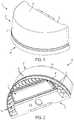
- FIG. 1is an upper perspective view of an exemplary luminaire.
- FIG. 2is a lower perspective view of the luminaire of FIG. 1 .
- FIG. 3is a lower perspective view of the luminaire of FIG. 1 , with a lens removed.
- FIG. 4is a lower perspective view of the luminaire of FIG. 1 , with a lens and light emitter assembly removed.
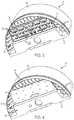
- FIG. 5is a cross-section view of the luminaire of FIG. 1 , viewed along section 5 - 5 .
- FIG. 6is a perspective view of a light emitter assembly support.
- FIG. 7is an upper perspective view of a luminaire according to another embodiment.
- FIG. 8is rear perspective view of the luminaire of FIG. 7 .
- FIG. 9is a lower perspective view of the luminaire of FIG. 7 .
- FIG. 10is an upper perspective view of a luminaire according to another embodiment.
- FIG. 11is a lower perspective view of the luminaire of FIG. 10 .
- FIG. 12is a perspective view of a light emitter assembly support.
- luminaire componentsthat provide a base assembly so that different exterior and interior components can be used with the base components to provide different aesthetic designs, interior controls, and light outputs.
- common housings and/or mounting featurescan accommodate different configurations of luminaires that include one or more different types of light emitters, and exterior features such as covers and lenses.
- the luminaire componentsalso provide efficient thermal management across the range of configurations. This allows customers to customize a luminaire to a desired architectural design within the same product line.
- FIGS. 1 and 2illustrate a wall pack luminaire 10 including a housing 12 , a light emitter assembly 14 , and a light emitter support 26 .
- the housing 12includes a rear wall or mounting wall 18 configured to connect to a mounting surface (not shown).
- An outer wall 30extends outwardly from the mounting wall 18 , and an upper wall 32 defines an upper surface of the housing 12 .
- the upper wall 32may be connected to both the mounting wall 18 and the outer wall 30 .
- the light emitter support 26may be secured to a lower end of the housing 12 and to the mounting wall 18 .
- the housing 12may be oriented such that the light emitter assembly 14 is oriented in a downward direction.
- the outer wall 30has a semi-cylindrical shape.
- the mounting wall 18includes flanges 22 for securing the housing 12 to the mounting surface (not shown), and an opening 70 for receiving a power supply conduit (e.g., main power).
- a power supply conduite.g., main power
- the light emitter assembly 14is secured to a lower surface of a base 34 ( FIG. 4 ) of the light emitter support 26 .
- the light emitter assembly 14includes light emitting diodes 36 (LEDs) secured to a substrate or lightboard 38 .
- the light emitter assembly 14includes a plurality of first LEDs 36 a and a plurality of second LEDs 36 b .
- a first type of lens or opticcan be positioned over the first LEDs 36 a and a second lens or optic can be positioned over the second LEDs 36 b so that the light distribution from the first LEDs 36 a is different than the light distribution from the second LEDs 36 b .
- An outer lens 40( FIG. 2 ) may extend over the LEDs.
- the outer lens 40can be translucent to simply provide cover the light emitters, or it can be configured to modify the light output.
- the first LEDs 36 a and the second LEDs 36 bmay be activated during normal operation, while the second LEDs 36 b alone are operated in a low-power or emergency mode (i.e., the second LEDs 36 b may be operated by a backup battery during a loss of mains power). In some embodiments, the second LEDs 36 b are activated during a lower-power or emergency mode only.
- a sensore.g., an occupancy sensor or ambient light sensor—not shown
- the light emitter support 26includes fins 50 for dissipating heat produced by the LEDs 36 and maintaining a desired operating temperature of the luminaire 10 .
- each fin 50extends orthogonally with respect to the base 34 and extends to the outer wall 30 . Stated another way, each fin 50 is oriented either in a direction that is substantially parallel to the mounting wall 18 or in a direction that is substantially perpendicular to the mounting wall 18 . In addition, each fin 50 extends downwardly from a plane of the base 34 toward the lower edge of the outer wall 30 .
- an upper surface of the light emitter support 26includes bosses 54 and a plurality of fastener holes 58 ( FIG. 5 ). Each fastener hole 58 is aligned with corresponding holes in one of the base 34 and a lower wall 62 of the housing 12 . Fasteners (e.g., screws) may be inserted through the holes 58 to secure the lightboard 38 to the base 34 and/or to secure the light emitter support 26 to the lower wall 62 . As shown in FIG. 5 , the housing 12 includes an enclosed compartment 66 defined between the upper wall 32 , the lower wall 62 , the outer wall 30 , and the mounting wall 18 .
- Mounting featuresallow control components (such as drivers, surge protectors, fuses, batteries, photocells, sensors, wireless communication devices, etc.) to be connected to the housing 12 .
- Other featuressuch as clips or protrusions may be used.
- the mounting featurescan directly connect control components or brackets can support and retain various control components in the enclosed compartment 66 . Accordingly, the lower wall 62 provides an insulating wall between the control components and the fins 50 and other heat dissipation structures of the light emitter support 26 .
- FIGS. 7-9illustrate a luminaire 210 according to another embodiment.
- the luminaire 210is similar to the luminaire 10 described above with respect to FIGS. 1-6 , and similar features are identified with similar reference numbers, plus 200. For the sake of brevity, only differences are described in detail.
- the luminaire 210includes a housing 212 including an outer wall 230 .
- the outer wall 230has a quarter spherical shape.
- the housing 212includes a compartment 266 that is partially enclosed by a lower wall 262 and an upper interior wall 274 .
- the lower wall 262is formed on a light emitter support 226 ( FIG. 8 ).
- FIGS. 10-12illustrate a luminaire 410 according to another embodiment.
- the luminaire 410is similar to the luminaire 10 described above with respect to FIGS. 1-6 , and similar features are identified with similar reference numbers, plus 400. For the sake of brevity, only differences are described in detail.
- the luminaire 410includes a housing 412 and a light emitter support 426 coupled to a lower end of the upper portion.
- the housing 412has a mounting wall 418 , a front wall 420 opposite the mounting wall 418 , an upper wall 432 , and side walls 448 .
- the housing 412defines a generally trapezoidal profile.
- a light emitter assembly 414is secured to the light emitter support 426 and includes a lens 440 to provide a desired light distribution.
- the support 426includes fins 450 , and each fin 50 is oriented either in a direction that is substantially parallel to the mounting wall 418 or in a direction that is substantially perpendicular to the mounting wall 418 .
- each fin 50extends downwardly from the plane of the light emitter assembly 414 toward the lower edge of the front wall 420 and side walls 448 .
- the terms “front,” “rear,” “upper,” “lower,” “upwardly,” “downwardly,” and other orientational descriptorsare intended to facilitate the description of the exemplary embodiments of the present application, and are not intended to limit the structure of the exemplary embodiments of the present application to any particular position or orientation.
- Terms of degree, such as “substantially” or “approximately”are understood by those of ordinary skill to refer to reasonable ranges outside of the given value, for example, general tolerances associated with manufacturing, assembly, and use of the described embodiments.
Landscapes
- Engineering & Computer Science (AREA)
- General Engineering & Computer Science (AREA)
- Architecture (AREA)
- Arrangement Of Elements, Cooling, Sealing, Or The Like Of Lighting Devices (AREA)
- Non-Portable Lighting Devices Or Systems Thereof (AREA)
Abstract
Description
Claims (20)
Priority Applications (2)
| Application Number | Priority Date | Filing Date | Title |
|---|---|---|---|
| US16/730,012US11041594B2 (en) | 2017-05-05 | 2019-12-30 | Wall pack luminaire |
| US17/348,028US11703195B2 (en) | 2017-05-05 | 2021-06-15 | Wall pack luminaire |
Applications Claiming Priority (3)
| Application Number | Priority Date | Filing Date | Title |
|---|---|---|---|
| US201762501851P | 2017-05-05 | 2017-05-05 | |
| US15/971,516US10520147B2 (en) | 2017-05-05 | 2018-05-04 | Wall pack luminaire |
| US16/730,012US11041594B2 (en) | 2017-05-05 | 2019-12-30 | Wall pack luminaire |
Related Parent Applications (1)
| Application Number | Title | Priority Date | Filing Date |
|---|---|---|---|
| US15/971,516ContinuationUS10520147B2 (en) | 2017-05-05 | 2018-05-04 | Wall pack luminaire |
Related Child Applications (1)
| Application Number | Title | Priority Date | Filing Date |
|---|---|---|---|
| US17/348,028ContinuationUS11703195B2 (en) | 2017-05-05 | 2021-06-15 | Wall pack luminaire |
Publications (2)
| Publication Number | Publication Date |
|---|---|
| US20200132265A1 US20200132265A1 (en) | 2020-04-30 |
| US11041594B2true US11041594B2 (en) | 2021-06-22 |
Family
ID=64015198
Family Applications (3)
| Application Number | Title | Priority Date | Filing Date |
|---|---|---|---|
| US15/971,516ActiveUS10520147B2 (en) | 2017-05-05 | 2018-05-04 | Wall pack luminaire |
| US16/730,012ActiveUS11041594B2 (en) | 2017-05-05 | 2019-12-30 | Wall pack luminaire |
| US17/348,028ActiveUS11703195B2 (en) | 2017-05-05 | 2021-06-15 | Wall pack luminaire |
Family Applications Before (1)
| Application Number | Title | Priority Date | Filing Date |
|---|---|---|---|
| US15/971,516ActiveUS10520147B2 (en) | 2017-05-05 | 2018-05-04 | Wall pack luminaire |
Family Applications After (1)
| Application Number | Title | Priority Date | Filing Date |
|---|---|---|---|
| US17/348,028ActiveUS11703195B2 (en) | 2017-05-05 | 2021-06-15 | Wall pack luminaire |
Country Status (6)
| Country | Link |
|---|---|
| US (3) | US10520147B2 (en) |
| EP (1) | EP3619459A4 (en) |
| CN (1) | CN111094835A (en) |
| CA (1) | CA3062540A1 (en) |
| MX (1) | MX388246B (en) |
| WO (1) | WO2018204815A1 (en) |
Families Citing this family (4)
| Publication number | Priority date | Publication date | Assignee | Title |
|---|---|---|---|---|
| EP3647656A1 (en)* | 2018-10-29 | 2020-05-06 | Eaton Intelligent Power Limited | Wallpack light fixture |
| USD905323S1 (en) | 2018-10-29 | 2020-12-15 | Eaton Intelligent Power Limited | Wallpack light fixture |
| USD1077324S1 (en)* | 2023-04-25 | 2025-05-27 | Guangzhou No Line Creation Culture Dept Co., Ltd. | Lamp |
| USD1095932S1 (en)* | 2023-06-05 | 2025-09-30 | Keystone Technologies, LLC | Semi-cylindrical lamp |
Citations (21)
| Publication number | Priority date | Publication date | Assignee | Title |
|---|---|---|---|---|
| US4426676A (en) | 1982-12-03 | 1984-01-17 | General Electric Company | Luminaire mounting |
| US4507719A (en) | 1983-11-17 | 1985-03-26 | Harvey Hubbell Incorporated | Heat dissipator for plastic luminaire |
| US20080080196A1 (en) | 2006-09-30 | 2008-04-03 | Ruud Lighting, Inc. | LED Floodlight Fixture |
| US20090120612A1 (en) | 2007-11-08 | 2009-05-14 | Fu Zhun Precision Industry (Shen Zhen) Co., Ltd. | Heat dissipation device for light emitting diode module |
| US20090296403A1 (en)* | 2008-05-28 | 2009-12-03 | Fu Zhun Precision Industry (Shen Zhen) Co., Ltd. | Led lamp |
| US20100002432A1 (en) | 2008-07-07 | 2010-01-07 | Hubbell Incorporated | Indirect luminaire utilizing led light sources |
| ITBS20100103A1 (en) | 2010-06-04 | 2011-12-04 | Italoiberica Engineering Group S L | SIGNALING AND LIGHT DRIVING SYSTEM FOR GALLERY ROUTES |
| US20120087118A1 (en) | 2010-10-07 | 2012-04-12 | Hubbell Incorporated | Led luminaire having lateral cooling fins and adaptive led assembly |
| US8283874B2 (en) | 2008-06-20 | 2012-10-09 | Energy Focus, Inc. | LED lighting system having a reduced-power usage mode |
| US20120268952A1 (en) | 2011-04-21 | 2012-10-25 | Chad Stuart Newton | Wall Pack Light Fixture |
| US8342709B2 (en) | 2008-10-24 | 2013-01-01 | Hubbell Incorporated | Light emitting diode module, and light fixture and method of illumination utilizing the same |
| US20140376221A1 (en) | 2013-06-19 | 2014-12-25 | Phoseon Technology, Inc. | Internal deflection venting |
| US9016892B1 (en) | 2014-10-08 | 2015-04-28 | Orion Energy Systems, Inc. | Light fixture with tool-less interchangeable lenses |
| US9109787B2 (en) | 2012-01-25 | 2015-08-18 | Hubbell Incorporated | Circular LED optic and heat sink module |
| US20150345772A1 (en) | 2014-05-30 | 2015-12-03 | Hubbell Incorporated | Area luminaire with heat fins |
| US20160305643A1 (en) | 2015-04-15 | 2016-10-20 | Hubbell Incorporated | Luminaire housing |
| US20160320035A1 (en) | 2015-04-30 | 2016-11-03 | Hubbell Incorporated | Modular area luminaire |
| US9521727B1 (en) | 2014-05-30 | 2016-12-13 | Cooper Technologies Company | Lighting fixture with motion sensor and battery test switch |
| CN206036792U (en) | 2016-08-18 | 2017-03-22 | 东莞市泰亮半导体照明有限公司 | Wall lamp of easy loading and unloading |
| WO2017156268A1 (en) | 2016-03-09 | 2017-09-14 | Hubbell Incorporated | Perimeter luminaire |
| US20170299170A1 (en) | 2016-04-19 | 2017-10-19 | Hubbell Incorporated | Wall pack luminaire and thermal insert for luminaires |
Family Cites Families (7)
| Publication number | Priority date | Publication date | Assignee | Title |
|---|---|---|---|---|
| KR20090106024A (en)* | 2008-04-04 | 2009-10-08 | 광주인탑스(주) | Optical system lighting device for beam shaping and sensor using fire |
| US20110051414A1 (en)* | 2009-08-28 | 2011-03-03 | Joel Brad Bailey | Lighting System with Beam Conditioning |
| CN102032521B (en)* | 2009-09-24 | 2013-08-07 | 富准精密工业(深圳)有限公司 | Light emitting diode lamp |
| EP3133340B1 (en)* | 2011-02-21 | 2019-05-22 | LG Innotek Co., Ltd. | Lighting module and lighting device |
| DK3175172T3 (en)* | 2014-08-01 | 2019-01-28 | Coast Cutlery Co | Dual focus flashlight |
| US10260718B2 (en)* | 2015-04-30 | 2019-04-16 | Hubbell Incorporated | Area luminaire |
| US9811985B2 (en)* | 2015-05-04 | 2017-11-07 | Ledsens Llc | Power outage safety light bulb |
- 2018
- 2018-05-04EPEP18794387.3Apatent/EP3619459A4/ennot_activeWithdrawn
- 2018-05-04MXMX2019013185Apatent/MX388246B/enunknown
- 2018-05-04CNCN201880045047.6Apatent/CN111094835A/enactivePending
- 2018-05-04CACA3062540Apatent/CA3062540A1/enactivePending
- 2018-05-04USUS15/971,516patent/US10520147B2/enactiveActive
- 2018-05-04WOPCT/US2018/031133patent/WO2018204815A1/ennot_activeCeased
- 2019
- 2019-12-30USUS16/730,012patent/US11041594B2/enactiveActive
- 2021
- 2021-06-15USUS17/348,028patent/US11703195B2/enactiveActive
Patent Citations (22)
| Publication number | Priority date | Publication date | Assignee | Title |
|---|---|---|---|---|
| US4426676A (en) | 1982-12-03 | 1984-01-17 | General Electric Company | Luminaire mounting |
| US4507719A (en) | 1983-11-17 | 1985-03-26 | Harvey Hubbell Incorporated | Heat dissipator for plastic luminaire |
| US20080080196A1 (en) | 2006-09-30 | 2008-04-03 | Ruud Lighting, Inc. | LED Floodlight Fixture |
| US20090120612A1 (en) | 2007-11-08 | 2009-05-14 | Fu Zhun Precision Industry (Shen Zhen) Co., Ltd. | Heat dissipation device for light emitting diode module |
| US20090296403A1 (en)* | 2008-05-28 | 2009-12-03 | Fu Zhun Precision Industry (Shen Zhen) Co., Ltd. | Led lamp |
| US8283874B2 (en) | 2008-06-20 | 2012-10-09 | Energy Focus, Inc. | LED lighting system having a reduced-power usage mode |
| US20100002432A1 (en) | 2008-07-07 | 2010-01-07 | Hubbell Incorporated | Indirect luminaire utilizing led light sources |
| US8342709B2 (en) | 2008-10-24 | 2013-01-01 | Hubbell Incorporated | Light emitting diode module, and light fixture and method of illumination utilizing the same |
| ITBS20100103A1 (en) | 2010-06-04 | 2011-12-04 | Italoiberica Engineering Group S L | SIGNALING AND LIGHT DRIVING SYSTEM FOR GALLERY ROUTES |
| US20120087118A1 (en) | 2010-10-07 | 2012-04-12 | Hubbell Incorporated | Led luminaire having lateral cooling fins and adaptive led assembly |
| US9523491B2 (en) | 2010-10-07 | 2016-12-20 | Hubbell Incorporated | LED luminaire having lateral cooling fins and adaptive LED assembly |
| US20120268952A1 (en) | 2011-04-21 | 2012-10-25 | Chad Stuart Newton | Wall Pack Light Fixture |
| US9109787B2 (en) | 2012-01-25 | 2015-08-18 | Hubbell Incorporated | Circular LED optic and heat sink module |
| US20140376221A1 (en) | 2013-06-19 | 2014-12-25 | Phoseon Technology, Inc. | Internal deflection venting |
| US20150345772A1 (en) | 2014-05-30 | 2015-12-03 | Hubbell Incorporated | Area luminaire with heat fins |
| US9521727B1 (en) | 2014-05-30 | 2016-12-13 | Cooper Technologies Company | Lighting fixture with motion sensor and battery test switch |
| US9016892B1 (en) | 2014-10-08 | 2015-04-28 | Orion Energy Systems, Inc. | Light fixture with tool-less interchangeable lenses |
| US20160305643A1 (en) | 2015-04-15 | 2016-10-20 | Hubbell Incorporated | Luminaire housing |
| US20160320035A1 (en) | 2015-04-30 | 2016-11-03 | Hubbell Incorporated | Modular area luminaire |
| WO2017156268A1 (en) | 2016-03-09 | 2017-09-14 | Hubbell Incorporated | Perimeter luminaire |
| US20170299170A1 (en) | 2016-04-19 | 2017-10-19 | Hubbell Incorporated | Wall pack luminaire and thermal insert for luminaires |
| CN206036792U (en) | 2016-08-18 | 2017-03-22 | 东莞市泰亮半导体照明有限公司 | Wall lamp of easy loading and unloading |
Non-Patent Citations (3)
| Title |
|---|
| European Patent Application No. 18794387.3 extended European search report and search opinion dated Dec. 1, 2020. |
| PCT/US2018/031133 International Search Report and Written Opinion dated Jul. 6, 2018 (18 pages). |
| PCT/US2018/031133 International Search Report and Written Opinion dated Jul. 6, 2018. |
Also Published As
| Publication number | Publication date |
|---|---|
| EP3619459A4 (en) | 2020-12-30 |
| WO2018204815A1 (en) | 2018-11-08 |
| US20210310625A1 (en) | 2021-10-07 |
| US20200132265A1 (en) | 2020-04-30 |
| MX388246B (en) | 2025-03-19 |
| US10520147B2 (en) | 2019-12-31 |
| EP3619459A1 (en) | 2020-03-11 |
| MX2019013185A (en) | 2020-02-07 |
| US20180320841A1 (en) | 2018-11-08 |
| US11703195B2 (en) | 2023-07-18 |
| CN111094835A (en) | 2020-05-01 |
| CA3062540A1 (en) | 2018-11-08 |
Similar Documents
| Publication | Publication Date | Title |
|---|---|---|
| US11703195B2 (en) | Wall pack luminaire | |
| US7614769B2 (en) | LED conversion system for recessed lighting | |
| KR101195745B1 (en) | Led lamp | |
| US10228111B2 (en) | Standardized troffer fixture | |
| US8382334B2 (en) | Lighting apparatus with heat dissipation system | |
| RU2476766C1 (en) | Led-using lighting device | |
| US9074743B2 (en) | LED based down light | |
| AU2016247786B2 (en) | Luminaire housing | |
| JP2012204162A (en) | Lighting device and lighting fixture | |
| US20100002452A1 (en) | Luminaire housing with separated lamp and ballast compartments | |
| AU2014203331B2 (en) | Lighting system | |
| KR200463465Y1 (en) | LED light | |
| US10746389B2 (en) | Wall pack luminaire and thermal insert for luminaires | |
| US11028999B2 (en) | Perimeter luminaire | |
| KR101191740B1 (en) | Structure body for fixing LED lamp | |
| US10119698B2 (en) | LED illumination device for spotlighting | |
| KR101905700B1 (en) | Led light | |
| US20110051418A1 (en) | Method and Apparatus Pertaining to Heat Sinking a Light Fixture Light-Emitting Diode | |
| US9068732B2 (en) | Air-cooled LED lamp bulb | |
| KR101157574B1 (en) | Led illumination lamp with open housing | |
| TWM448621U (en) | LED lamp for light steel frame |
Legal Events
| Date | Code | Title | Description |
|---|---|---|---|
| FEPP | Fee payment procedure | Free format text:ENTITY STATUS SET TO UNDISCOUNTED (ORIGINAL EVENT CODE: BIG.); ENTITY STATUS OF PATENT OWNER: LARGE ENTITY | |
| AS | Assignment | Owner name:HUBBELL INCORPORATED, CONNECTICUT Free format text:ASSIGNMENT OF ASSIGNORS INTEREST;ASSIGNORS:ELMORE, MARK;DUCKWORTH, JASON;REEL/FRAME:052580/0868 Effective date:20191004 | |
| STPP | Information on status: patent application and granting procedure in general | Free format text:NOTICE OF ALLOWANCE MAILED -- APPLICATION RECEIVED IN OFFICE OF PUBLICATIONS | |
| STPP | Information on status: patent application and granting procedure in general | Free format text:PUBLICATIONS -- ISSUE FEE PAYMENT RECEIVED | |
| STPP | Information on status: patent application and granting procedure in general | Free format text:PUBLICATIONS -- ISSUE FEE PAYMENT VERIFIED | |
| STCF | Information on status: patent grant | Free format text:PATENTED CASE | |
| AS | Assignment | Owner name:HUBBELL LIGHTING, INC., CONNECTICUT Free format text:NUNC PRO TUNC ASSIGNMENT;ASSIGNOR:HUBBELL INCORPORATED;REEL/FRAME:058838/0162 Effective date:20220112 | |
| AS | Assignment | Owner name:ALLY BANK, AS COLLATERAL AGENT, NEW YORK Free format text:SECURITY AGREEMENT;ASSIGNORS:HUBBELL LIGHTING, INC.;LITECONTROL CORPORATION;CURRENT LIGHTING SOLUTIONS, LLC;AND OTHERS;REEL/FRAME:058982/0844 Effective date:20220201 | |
| AS | Assignment | Owner name:ATLANTIC PARK STRATEGIC CAPITAL FUND, L.P., AS COLLATERAL AGENT, NEW YORK Free format text:SECURITY INTEREST;ASSIGNORS:HUBBELL LIGHTING, INC.;LITECONTROL CORPORATION;CURRENT LIGHTING SOLUTIONS, LLC;AND OTHERS;REEL/FRAME:059034/0469 Effective date:20220201 | |
| AS | Assignment | Owner name:ALLY BANK, AS COLLATERAL AGENT, NEW YORK Free format text:CORRECTIVE ASSIGNMENT TO CORRECT THE PATENT NUMBER 10841994 TO PATENT NUMBER 11570872 PREVIOUSLY RECORDED ON REEL 058982 FRAME 0844. ASSIGNOR(S) HEREBY CONFIRMS THE SECURITY AGREEMENT;ASSIGNORS:HUBBELL LIGHTING, INC.;LITECONTROL CORPORATION;CURRENT LIGHTING SOLUTIONS, LLC;AND OTHERS;REEL/FRAME:066355/0455 Effective date:20220201 | |
| AS | Assignment | Owner name:ATLANTIC PARK STRATEGIC CAPITAL FUND, L.P., AS COLLATERAL AGENT, NEW YORK Free format text:CORRECTIVE ASSIGNMENT TO CORRECT THE PATENT NUMBER PREVIOUSLY RECORDED AT REEL: 059034 FRAME: 0469. ASSIGNOR(S) HEREBY CONFIRMS THE SECURITY INTEREST;ASSIGNORS:HUBBELL LIGHTING, INC.;LITECONTROL CORPORATION;CURRENT LIGHTING SOLUTIONS, LLC;AND OTHERS;REEL/FRAME:066372/0590 Effective date:20220201 | |
| MAFP | Maintenance fee payment | Free format text:PAYMENT OF MAINTENANCE FEE, 4TH YEAR, LARGE ENTITY (ORIGINAL EVENT CODE: M1551); ENTITY STATUS OF PATENT OWNER: LARGE ENTITY Year of fee payment:4 |