US11040768B2 - Method and a device for moving the center of gravity of an aircraft - Google Patents
Method and a device for moving the center of gravity of an aircraftDownload PDFInfo
- Publication number
- US11040768B2 US11040768B2US16/821,194US202016821194AUS11040768B2US 11040768 B2US11040768 B2US 11040768B2US 202016821194 AUS202016821194 AUS 202016821194AUS 11040768 B2US11040768 B2US 11040768B2
- Authority
- US
- United States
- Prior art keywords
- aircraft
- thrust production
- production unit
- adjustment device
- failure
- Prior art date
- Legal status (The legal status is an assumption and is not a legal conclusion. Google has not performed a legal analysis and makes no representation as to the accuracy of the status listed.)
- Active
Links
- 230000005484gravityEffects0.000titleclaimsabstractdescription32
- 238000000034methodMethods0.000titleclaimsdescription19
- 238000004519manufacturing processMethods0.000claimsabstractdescription170
- 238000013519translationMethods0.000claimsdescription17
- 238000004146energy storageMethods0.000claimsdescription11
- 230000000087stabilizing effectEffects0.000claimsdescription2
- 238000004364calculation methodMethods0.000description35
- 238000010586diagramMethods0.000description15
- 230000006870functionEffects0.000description13
- 238000012544monitoring processMethods0.000description10
- RZVHIXYEVGDQDX-UHFFFAOYSA-N9,10-anthraquinoneChemical compoundC1=CC=C2C(=O)C3=CC=CC=C3C(=O)C2=C1RZVHIXYEVGDQDX-UHFFFAOYSA-N0.000description5
- 230000005611electricityEffects0.000description5
- 238000003032molecular dockingMethods0.000description4
- 230000001052transient effectEffects0.000description4
- 230000001133accelerationEffects0.000description2
- 230000000712assemblyEffects0.000description2
- 238000000429assemblyMethods0.000description2
- 230000003247decreasing effectEffects0.000description2
- 239000002360explosiveSubstances0.000description2
- 238000004088simulationMethods0.000description2
- 238000012360testing methodMethods0.000description2
- 230000005355Hall effectEffects0.000description1
- 230000004913activationEffects0.000description1
- 230000003466anti-cipated effectEffects0.000description1
- 238000007796conventional methodMethods0.000description1
- 230000002950deficientEffects0.000description1
- 230000001419dependent effectEffects0.000description1
- 238000001514detection methodMethods0.000description1
- 230000000694effectsEffects0.000description1
- 238000005516engineering processMethods0.000description1
- 239000000446fuelSubstances0.000description1
- 230000002452interceptive effectEffects0.000description1
- 238000005259measurementMethods0.000description1
- 230000000149penetrating effectEffects0.000description1
Images


Classifications
- B—PERFORMING OPERATIONS; TRANSPORTING
- B64—AIRCRAFT; AVIATION; COSMONAUTICS
- B64C—AEROPLANES; HELICOPTERS
- B64C17/00—Aircraft stabilisation not otherwise provided for
- B64C17/02—Aircraft stabilisation not otherwise provided for by gravity or inertia-actuated apparatus
- B—PERFORMING OPERATIONS; TRANSPORTING
- B64—AIRCRAFT; AVIATION; COSMONAUTICS
- B64C—AEROPLANES; HELICOPTERS
- B64C17/00—Aircraft stabilisation not otherwise provided for
- B64C17/02—Aircraft stabilisation not otherwise provided for by gravity or inertia-actuated apparatus
- B64C17/04—Aircraft stabilisation not otherwise provided for by gravity or inertia-actuated apparatus by pendular bodies
- B—PERFORMING OPERATIONS; TRANSPORTING
- B64—AIRCRAFT; AVIATION; COSMONAUTICS
- B64C—AEROPLANES; HELICOPTERS
- B64C27/00—Rotorcraft; Rotors peculiar thereto
- B64C27/32—Rotors
- B—PERFORMING OPERATIONS; TRANSPORTING
- B64—AIRCRAFT; AVIATION; COSMONAUTICS
- B64U—UNMANNED AERIAL VEHICLES [UAV]; EQUIPMENT THEREFOR
- B64U40/00—On-board mechanical arrangements for adjusting control surfaces or rotors; On-board mechanical arrangements for in-flight adjustment of the base configuration
- B64U40/20—On-board mechanical arrangements for adjusting control surfaces or rotors; On-board mechanical arrangements for in-flight adjustment of the base configuration for in-flight adjustment of the base configuration
- B—PERFORMING OPERATIONS; TRANSPORTING
- B64—AIRCRAFT; AVIATION; COSMONAUTICS
- B64U—UNMANNED AERIAL VEHICLES [UAV]; EQUIPMENT THEREFOR
- B64U10/00—Type of UAV
- B64U10/10—Rotorcrafts
- B64U10/13—Flying platforms
- B—PERFORMING OPERATIONS; TRANSPORTING
- B64—AIRCRAFT; AVIATION; COSMONAUTICS
- B64U—UNMANNED AERIAL VEHICLES [UAV]; EQUIPMENT THEREFOR
- B64U2101/00—UAVs specially adapted for particular uses or applications
- B64U2101/60—UAVs specially adapted for particular uses or applications for transporting passengers; for transporting goods other than weapons
- B64U2101/61—UAVs specially adapted for particular uses or applications for transporting passengers; for transporting goods other than weapons for transporting passengers
- B—PERFORMING OPERATIONS; TRANSPORTING
- B64—AIRCRAFT; AVIATION; COSMONAUTICS
- B64U—UNMANNED AERIAL VEHICLES [UAV]; EQUIPMENT THEREFOR
- B64U2201/00—UAVs characterised by their flight controls
- B—PERFORMING OPERATIONS; TRANSPORTING
- B64—AIRCRAFT; AVIATION; COSMONAUTICS
- B64U—UNMANNED AERIAL VEHICLES [UAV]; EQUIPMENT THEREFOR
- B64U30/00—Means for producing lift; Empennages; Arrangements thereof
- B64U30/20—Rotors; Rotor supports
- B—PERFORMING OPERATIONS; TRANSPORTING
- B64—AIRCRAFT; AVIATION; COSMONAUTICS
- B64U—UNMANNED AERIAL VEHICLES [UAV]; EQUIPMENT THEREFOR
- B64U50/00—Propulsion; Power supply
- B64U50/10—Propulsion
- B64U50/19—Propulsion using electrically powered motors
Definitions
- the present inventionrelates to a method and to a device for moving the center of gravity of an aircraft, and it also relates to an aircraft applying the method.
- the aircraftmay be a drone, i.e. an aircraft without a human pilot on board, which aircraft might carry goods and/or passengers.
- An aircraftmay comprise an airframe and a plurality of thrust production units, each contributing to providing the aircraft with lift, and possibly also with propulsion.
- each thrust production unitmay be carried by a body of the airframe via a fastener structure.
- Each thrust production unitmay comprise at least one rotor and at least one motor, each rotor having blades that are rotated by the motor.
- each thrust production unitmay comprise one or more thrust production systems.
- each thrust production unitmay comprise two rotors that are rotated respectively by two dedicated motors.
- the term “rotor system”is used to designate a system comprising a rotor having blades and a motor, where a motor may be dedicated to a single rotor assembly or may be common to a plurality of rotor assemblies.
- An aircraftmay have at least two thrust production units, and by way of example it may have four thrust production units arranged substantially at four corners of a quadrilateral.
- the aircraftis controlled by controlling each thrust production unit.
- this controlcan be obtained by controlling the speed of rotation of the rotors and/or the pitch of the rotor blades, while the direction of rotation of the rotors may be constant.
- Document US 2018/141647describes a four-rotor aircraft. That aircraft comprises an entity having four arms, each carrying a respective one of the four rotors. The aircraft also has a rod carrying a first assembly and possibly also a second assembly, which assemblies are situated on opposite sides of said entity along a direction. Said entity is movable relative to the first assembly, and also to the second assembly, if present.
- Document US 2016/264234describes a method and a device for balancing an aircraft by adjusting the position of its center of gravity.
- Document CN 207 725 615is a utility model relating to a drone. That drone has arms carrying rotors. An arm may include a linear motor connected to a balancing weight.
- Document CN 106 218 877relates to a multirotor drone that is fuel-driven and that is provided with an attitude adjusting and changing device.
- An object of the present inventionis thus to propose a device seeking at least to limit the risks of an accident as a result of unbalance, in particular following a failure of a thrust production unit.
- the inventionprovides an adjustment device for adjusting the position of the center of gravity of an aircraft, the aircraft including at least two thrust production units, or indeed at least three or four thrust production units, each of which contributes at least to providing the aircraft with lift, and possibly also with propulsion.
- the adjustment devicecomprises at least one heavy member that is movable relative to an airframe of the aircraft, the adjustment device comprising at least one actuator for causing said heavy member to move.
- the adjustment deviceincludes an avionics system configured to detect a failure of any one of the thrust production units and, in the presence of a failure of at least one thrust production unit, to control said at least one actuator for causing said heavy member to move.
- the aircraftmay be a drone.
- the term “avionics system”designates a system comprising in particular one or more on-board calculation means and possibly also various sensors.
- the avionics systemmay comprise one or more calculation means, and by way of example calculation means of the type usually present on an aircraft.
- the avionics systemmay comprise flight control calculation means serving in particular to prepare setpoints for following a path, and/or regulation calculation means controlling motors to follow setpoints that have been issued, and/or monitoring calculation means that monitor the operation of the aircraft, and/or calculation means dedicated to applying the invention.
- at least some of the calculation meansmay be provided in redundant manner.
- Several of the above-mentioned calculation meansmay be combined in single calculation means.
- Each thrust production unitmay comprise one or more thrust production systems, and for example it may comprise one or more rotor systems.
- the regulation deviceincludes a member or a set of members referred to, for convenience, as the “avionics system”, and capable of estimating in conventional manner whether a thrust production unit has failed.
- a failuremay be a failure that has an influence on the thrust generated by at least one thrust production system of the thrust production unit that is considered to have failed, and its thrust might even become zero in untimely manner.
- Such a failurecould be referred to as a “partial or total failure of thrust”, but is referred to more simply merely as a “failure”.
- the avionics systemcontrols at least one actuator to move at least one heavy member in order to change the position of the center of gravity of the aircraft.
- such a failure of a thrust production unitcan change the attitude of the aircraft or can lead to losing control of the aircraft in the event of a total failure of the thrust production unit.
- the position of the center of gravityis modified without human intervention so as to be adapted to the new thrust configuration of the aircraft, and/or so as to anticipate worsening of the failure that might lead to a new thrust configuration.
- the aircraftis easier to control so long as the center of gravity of the aircraft lies substantially within a first acceptable zone defined by the thrust production units, and in particular so long as it is present in a first polygon if there are three or more thrust production units, with the corners of the first polygon being located at the thrust production units.
- the first zoneno longer necessarily represents an acceptable zone in which the center of gravity of the aircraft should be located in order to avoid unbalance, and a new acceptable zone might possibly be present within a second polygon defined by the thrust production units that remain in operation, depending on the number of such units.
- the avionics systemuses at least one actuator to cause at least one heavy member to move so as to tend to move the position of the center of gravity of the aircraft into the new acceptable zone. Moving the center of gravity tends to enable an autopilot system to keep control of the aircraft in applications where a high level of availability and safety is required, possibly with an accompanying loss of performance.
- the adjustment devicemay also include one or more of the following characteristics, taken singly or in combination.
- the heavy membermay include at least one electrical energy storage member.
- the heavy membercan be any member. Nevertheless, in the presence of one or more electrical energy storage members, and for example on an aircraft of the electric drone type, each electrical energy storage member presents considerable weight at high density, i.e. considerable weight occupying little space. It is therefore advantageous to use at least one electrical energy storage member as a heavy member that is movable for changing the position of the center of gravity.
- each electrical energy storage membermay comprise one or more batteries.
- a plurality of distinct electrical energy storage membersmay be suitable for being moved singly and/or jointly as a function of the location of each thrust production unit that has failed.
- said actuatormay include at least one jack for moving at least one heavy member in translation along at least one axis.
- a jackmay exert a force on a heavy member directly, or it may exert a force on a support that is secured to a heavy member.
- Each heavy membermay be moved directly or indirectly by at least one jack.
- membermay be moved directly or indirectly by at least one jack” means that a jack may act on the heavy member itself or on a member connected to the heavy member.
- a possibly linear first jackmay be connected to at least one heavy member in order to move the heavy member parallel to at least one roll axis of the aircraft.
- an optionally linear second jackmay be connected to the assembly comprising the first jack and the heavy member in order to move the heavy member and the first jack parallel to a pitching axis of the aircraft.
- each jackmay serve to move a heavy member along an arbitrary axis determined as a function of the number of thrust production units and of their positions.
- said actuatormay be designed to move a heavy member very quickly so as to avoid being subjected to a lengthy transient period during which the aircraft runs the risk of being unbalanced.
- At least one thrust production unitmay be a multisystem unit having at least two thrust production systems.
- a thrust production unitmay comprise two rotors driven in rotation by a single motor of the thrust production unit, or else each rotor may be rotated by its own dedicated motor.
- At least one heavy membermay be moved when one or all of the thrust production systems of a multisystem thrust production unit have failed, i.e. have stopped or are operating in degraded manner, for example.
- a heavy memberneeds to be moved only when all of the thrust production systems of a multisystem thrust production unit have failed.
- a heavy membermay be caused to move as soon as any one of the thrust production systems of a multisystem thrust production unit has failed.
- an actuatormay comprise at least one resilient member and a blocker, the blocker being controlled by the avionics system to act directly or indirectly to prevent said resilient member from moving in the absence of a said failure of at least one thrust production unit.
- the resilient membermay be a member that stretches or that retracts on being released by the blocker.
- the term “to act directly or indirectly to prevent said resilient member from moving”means that the blocker may act on the resilient member or on the heavy member or on some other member connected to the heavy member and/or to the resilient member, for example.
- such a resilient actuatormay comprise a resilient member of the spring type.
- the spring or the heavy membermay be blocked by a finger. If a failure is detected, the finger is moved in order to release the spring.
- an electromagnet or a pyrotechnic systemmay be used for moving the finger quickly.
- Said actuatormay be designed to move a heavy member very quickly so as to avoid being subjected to a lengthy transient period during which the aircraft runs the risk of being unbalanced.
- a heavy membermay slide along a slideway, the slideway possibly including abutments for safety purposes.
- the adjustment devicemay include a respective heavy member fastened in the proximity of each thrust production unit.
- the adjustment devicemay have at least as many heavy members as there are thrust production units. In the absence of a failure, at least one heavy member is arranged in the proximity of an associated thrust production unit.
- the term “associated”refers to the thrust production unit situated in the proximity of a particular heavy member, and vice versa.
- the term “in the proximity of”means that a particular heavy member is closer to the thrust production unit associated therewith than it is to the other thrust production units.
- an aircraftmay comprise a central body, with each thrust production unit being connected to the central body by a fastener structure or the equivalent.
- each heavy membermay be carried by a fastener structure connected to the associated thrust production unit in order to be located in the proximity of that thrust production unit.
- each heavy membermay be carried by a slide that is movable in translation, the adjustment device having a respective said actuator for each slide, each said actuator being connected to a slide in order to move that slide in translation.
- the slide and the heavy member secured to the slidemove towards a geometrical center of the aircraft in the event of the associated thrust production unit failing, or they are moved away from the geometrical center in the event of a failure of the thrust production unit that is arranged opposite from the associated thrust production unit.
- the adjustment deviceincludes a respective heavy member fastened in the proximity of each thrust production unit, each heavy member being carried by a slide that is movable in translation, said adjustment device including a respective said actuator for each slide, said actuator being connected to a slide to move said slide in translation.
- an adjustment devicemay include a respective heavy member for each thrust production unit, each heavy member being secured to a movable link connected to said airframe, said adjustment device being provided with a respective said actuator configured to attach each heavy member to the airframe in the event of a said failure of at least one thrust production unit.
- each linkmay be in the form of a cord or the equivalent.
- a linkmay also be in the form of an arm that is movable in rotation relative to the airframe under the effect of gravity, and for example it may be in the form of a connection arm hinged to the airframe by a pivot or ball-joint type connection in the proximity of the geometrical center of the aircraft.
- the actuatoris a securing device that is different from the link and that secures the heavy member to the airframe in the absence of a failure.
- Such a systemmay be designed to move a heavy member very quickly so as to avoid being subjected to a lengthy transient period during which the aircraft runs the risk of being unbalanced.
- the heavy memberis fastened by an actuator to the airframe of the aircraft in the proximity of a thrust production unit, which thrust production unit is offset away from the geometrical center of the aircraft.
- the actuatorreleases the associated heavy member and the heavy member then moves, e.g. by gravity, so as to be substantially in register with the geometrical center of the aircraft under guidance from the link.
- said actuatormay include both a ring in said any member and also a jack, the jack having a rod that is movable in translation, with said rod penetrating into said ring in the absence of a said failure of at least one thrust production unit.
- the jackIn the presence of a failure, the jack is activated to disengage the rod from the ring, thereby enabling the heavy member to be released, potentially very quickly.
- said actuatormay comprise a motor-driven clamp.
- the clampIn the absence of a failure, the clamp is closed so as to clamp onto the heavy member or onto a support of the heavy member. In the presence of a failure, the clamp opens in order to release the heavy member, potentially very quickly.
- said actuatormay comprise at least one pyrotechnic device configured to link said heavy member to said airframe in the absence of a said failure of at least one thrust production unit.
- a pyrotechnic devicesuch as explosive bolts, may also be used for separating the heavy member quickly from its support.
- the linkmay be suitable for being jettisoned.
- the link and the heavy member carried by the linkmay be jettisoned in an appropriate location immediately prior to landing.
- jettisoningis all the more possible when the heavy member comprises a battery for electrically powering only the thrust production unit that has failed.
- an electric jettisoning motor, an electromagnet, or a pyrotechnic membermay be linked to a connection pin connecting the link to a body of the aircraft. Prior to landing, the pin is disengaged from the connection in order to jettison the link.
- the linkmay comprise a foldable arm.
- the aircraftmay land on a docking station that includes an orifice suitable for receiving the heavy member that is hanging down as a result of a failure.
- the aircraftmay include landing gear that is tall enough to avoid any interference while landing.
- the inventionalso provides an aircraft having an airframe, said airframe carrying at least two thrust production units that contribute at least to providing the aircraft with lift or indeed with propulsion, the aircraft including an adjustment device of the invention.
- the inventionalso provides a method of stabilizing an aircraft, said aircraft having at least two thrust production units, each contributing at least to providing the aircraft with lift or indeed with propulsion.
- the methodcomprises the following steps: detecting a failure of a thrust production unit; and as a result of detecting a failure of a thrust production unit, causing a movement of a heavy member to move from a current position to an emergency position in order to modify the position of the center of gravity of the aircraft, e.g. in order to re-center the center of gravity in a zone that is predefined as a function of the thrust production units that are still in nominal operation.
- the methodmay include one or more of the following characteristics, taken singly or in combination.
- each thrust production unitmay comprise two rotor systems, each rotor system comprising both a motor and a rotor provided with a plurality of blades, and detecting a failure of a thrust production unit may include a step of detecting a failure of either one of the two rotor systems.
- a thrust production unitcomprises a plurality of different thrust production systems
- the operation of moving a heavy membermay be anticipated and may take place as soon as any one of the thrust production systems becomes defective.
- the emergency positionis a stored position that depends on the thrust production unit that has failed, or indeed on the thrust production system that has failed.
- the emergency position that is to be reachedmay be a predetermined position that depends on the thrust production unit that has failed. For example, for each possible failure configuration, an emergency position may be determined by testing, by calculation, and/or by simulation. For example, on an aircraft having four thrust production units, the avionics system may store four emergency positions, each associated with a different one of the thrust production units failing.
- the avionics systemcan then select the appropriate position for each heavy member from a list of predetermined positions, each predetermined position being a position that is to be reached by the heavy member in the event of a failure of one or more particular thrust production units.
- the avionics systemmay store, e.g. in a memory, at least one emergency position to be reached and the heavy member(s) to be moved.
- said methodmay include a step of calculating with the avionic system the emergency position that is to be reached as a function of a stored model, while taking into consideration at least the thrust production unit that has failed.
- said stored modelalso takes into consideration at least the weight of a payload on board the aircraft and/or the airspeed or the equivalent of the aircraft.
- the stored emergency positionmay be replaced by a position calculated by the avionics system of the aircraft.
- a respective heavy membermay be fastened in the proximity of each thrust production unit, said movement comprising a step of causing the heavy member situated in the proximity of the thrust production unit that has been detected as failing to move towards a geometrical center of the aircraft, or a step of causing the heavy member that is situated in the proximity of a thrust production unit that is arranged opposite from the thrust production unit that has been detected as failing to move away from said geometrical center.
- FIG. 1is a diagram showing an aircraft of the invention having thrust production units in operation
- FIG. 2is a diagram showing an example of a thrust production unit
- FIG. 3is a diagram showing an aircraft of the invention the having a thrust production unit that has failed;
- FIG. 4is a diagram showing an aircraft of the invention and presenting a movement of a heavy member following the failure of a thrust production unit;
- FIG. 5is a diagram showing a heavy member located in the proximity of a thrust production unit
- FIG. 6is a diagram showing a heavy member that has moved to the outside of the aircraft
- FIG. 7is a diagram showing an actuator moving a heavy member in translation, the actuator being provided with a blocker and with a resilient member;
- FIG. 8is a diagram showing such a blocker of a FIG. 7 actuator
- FIG. 9is a diagram showing the movement of a heavy member under drive from an actuator of FIG. 7 ;
- FIG. 10is a diagram showing a heavy member secured to a movable link
- FIG. 11is a diagram showing a pyrotechnic actuator
- FIG. 12is a diagram showing an actuator having a closed camp
- FIG. 13is a diagram showing the FIG. 12 actuator with the clamp open
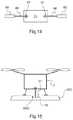
- FIG. 14is a diagram showing an actuator comprising a jack and a ring.
- FIG. 15is a diagram showing an aircraft standing on a hollow docking station.
- FIG. 1shows an aircraft 1 provided with an adjustment device 10 of the invention.
- FIG. 1shows a drone type aircraft 1 , and by way of illustration a multirotor drone.
- the aircraft 1could be an aircraft having at least one on-board pilot and/or an airplane and/or a rotorcraft and/or an aircraft suitable for vertical takeoff and landing (VTOL).
- VTOLvertical takeoff and landing
- the aircraft 1has an airframe 2 .
- the airframe 2comprises a body 3 that may be referred to, for convenience, as a “central” body.
- the body 3extends longitudinally from rear to front parallel to a roll axis AXROL of the aircraft 1 and transversely parallel to a pitching axis AXTANG of the aircraft 1 .
- the body 3may define one or more internal volumes 3 a .
- Each internal volume 3 amay be adapted to transport passengers, such that the aircraft 1 as a whole may be adapted for transporting passengers. If so desired, the internal volume 3 a may be adapted to receive at least a portion of the electrical and operating equipment of the aircraft 1 .
- the aircraft 1may have an arbitrary number of thrust production units 5 , there being at least two of them.
- the aircraft 1may have four thrust production units.
- Each thrust production unit 5exert thrust that contributes to providing the aircraft 1 with lift and possibly also with propulsion in any direction, downwards, upwards, forwards, rearwards, or sideways.
- Each thrust production unit 5is connected to the body 3 of the airplane 2 by at least one structural support 4 .
- Each thrust production unit 5is then attached to a corresponding structural support 4 , with the structural support 4 being attached to the body 3 .
- Such a structural support 4may be in the form of an optionally hollow arm.
- the body 3 and the structural supportsmay form a structure that is H- or X-shaped.
- each thrust production unit 5may comprise at least one rotor system 6 , with the aircraft 1 being a multirotor aircraft. It is possible to envisage other thrust production units.
- each thrust production unit 5may comprise a plurality of thrust production systems, and for example such a unit may comprise two rotor systems 6 .
- Each rotor system 6may comprise both a motor 9 , e.g. an electric motor, and also a rotor 7 having blades 8 .
- each motor 9 of a thrust production unit 5may be carried by a respective structural support 4 , the blades 8 being carried by a motor 9 via a hub or the equivalent.
- each thrust production unit 5may include a fairing 500 that is carried by the body 3 and/or by a structural support 4 .
- the aircraft 1may be controlled by varying the pitch of the blades 8 of at least one rotor system 6 , or by varying the speed of rotation of said blades 8 , or by a combination of varying both pitch and speed of rotation.
- the aircraft 1includes an adjustment device 10 for adjusting the position of the center of gravity 100 of the aircraft 1 as a function of the state of operation of each thrust production unit 5 .
- the adjustment device 10is provided with at least one member referred to as a “heavy” member 15 in order to distinguish it from the other members of the device.
- Each heavy member 15 of the adjustment device 10is movable in the reference frame of the aircraft 1 .
- each heavy member 15may be carried by the body 3 , by a structural support 4 , or indeed by a thrust production unit 5 in the absence of a failure.
- At least one heavy member 15may comprise an electrical energy storage member 16 .
- the aircraft 1may have a respective electrical energy storage member 16 for each thrust production unit 5 or indeed for each thrust production system, and where appropriate for each rotor system 6 , with one, or more, or all of the electrical energy storage members 16 being movable relative to the airframe.
- At least one heavy member 15may be made to be movable directly and/or it may be carried by a support that is itself movable in the reference frame of the aircraft. Under all circumstances, the heavy member 15 is made to be movable in the reference frame of the aircraft 1 , being capable of reaching at least two distinct positions, thereby causing the center of gravity 100 of the aircraft 1 take up two different positions in this reference frame of the aircraft 1 .
- the adjustment device 10includes an avionics system 20 that is configured to detect a failure leading to a change in the thrust generated by at least one thrust production unit 5 . Furthermore, the avionics system 20 is connected to at least one actuator 40 , and it is configured to control at least one actuator 40 so as to cause at least one heavy member 15 to move in the presence of such a failure, either by moving the heavy member 15 directly, or else by moving a member that is secured thereto, for example.
- FIG. 2shows an example of an avionics system 20 .
- Such an avionics system 20may comprise one or more calculation means, e.g. using conventional methods for detecting the failure of a thrust production unit 5 , and where applicable for causing one or more actuators 40 to operate.
- the term “calculation means”should be interpreted broadly, and by way of example, calculation means may comprise at least one processor with at least one memory, at least one integrated circuit, at least one programmable system, at least one logic circuit, these examples not limiting the scope to be given to the term “calculation means”.
- each thrust production unit 5may comprise at least one rotor system 6 , and for example it may comprise two rotor systems 6 , each provided with a respective electric motor 9 .
- the avionics system 20includes flight control calculation means 22 that determine a control setpoint for each motor 9 and/or for systems for modifying the pitch of the blades in order to follow a path.
- the pathmay be stored in memory or it may be established in flight by various means.
- Each control setpointmay be established by a subassembly referred to for convenience as “flight control” calculation means 22 , which subassembly takes account of flight data coming from conventional flight sensors 25 .
- the control setpointsmay be in the form of setpoints for the speeds of rotation of the electric motors 9 of the thrust production units 5 or in the form of pitch setpoints for the blades 8 of the thrust production units 5 .
- the control setpointsmay be determined in conventional manner.
- Each control setpointis optionally transmitted by the flight control calculation means 22 to regulation electronics 30 serving to servocontrol one or more motors 9 of the thrust production units 5 and/or to a device for modifying the pitch of the blades.
- the servocontrolmay be performed by servocontrol calculation means 31 using a plurality of regulation loops as a function of measurements coming from movement sensors 34 serving to measure a position or a speed or an acceleration and installed on the motors 9 , together with sensors 33 for measuring the electricity consumed by each electric motor 9 .
- the movement sensors 34 and the electricity measuring sensors 33are connected to the servocontrol calculation means 31 .
- the movement sensors 34may be of various kinds: a Hall effect sensor, a sin-cos sensor, a “resolver”, an encoder, a tachometer, an accelerometer, etc . . . .
- the regulation electronics 30may include a respective power bridge 32 dedicated to each electric motor 9 .
- the power bridges 32 and the servocontrol calculation means 31are connected to an electricity storage member 16 .
- Each power bridge 32is then controlled by the servocontrol calculation means 31 to allow the desired electricity to flow to each electric motor 9 in order to reach the initial control setpoint.
- monitoring calculation means 23may be integrated directly in the regulation electronics 30 or in calculation means 21 integrating the flight control calculation means 22 in the example shown in order to determine whether at least one of said thrust production units 5 has failed, i.e. in order to determine whether a thrust production unit 5 is not generating the appropriate thrust or whether a thrust production system of a thrust production unit is not generating the appropriate thrust. Where appropriate, the monitoring calculation means 23 may determine whether any one of the thrust production systems of a thrust production unit has failed.
- the monitoring calculation means 23may signal that a motor has failed in the event of an electricity measuring sensor 33 measuring zero current, even though the servocontrol calculation means 31 have issued an order transmit electric current.
- the monitoring calculation means 23may indicate that a motor has failed if the electric motor 9 presents a speed of rotation as determined by a movement sensor 34 that is decreasing relative to a theoretical expected speed as estimated by an on-board motor model.
- This measured speed of rotationmay be estimated by taking the derivative of the position measured using a movement sensor 34 of the position sensor type, or else directly by a speed sensor such as a tachometer, or indeed by integrating an acceleration measured by a movement sensor 34 of the accelerometer type.
- the on-board motor modelmay be determined by testing, by calculation, or by simulation in order to supply a theoretical expected speed of rotation for the motor, e.g.
- the monitoring calculation means 23deduce that the system has suffered a failure. Under such circumstances, the monitoring calculation means 23 order one or more actuators 40 to cause at least one heavy member 15 to move, and consequently move the center of gravity 100 of the aircraft 1 .
- the aircraft 1may have a plurality of sensors and/or calculation means in order to construct failure information that is reliable.
- Command monitor architecture or voted architecture techniquescan be used to guarantee the integrity of the processed information.
- the monitoring calculation means 23 used for failure detectioncan also use their outputs to activate the actuators 40 directly.
- the monitoring calculation means 23may control one pole with its command channel for electrically powering a “+” terminal of an actuator, and may control another pole with its monitoring channel for electrically powering a “ ⁇ ” terminal of the actuator.
- FIGS. 3 to 6show the method of the invention.
- the avionics system 20detects the failure of a thrust production unit.
- the avionics system 20includes at least one heavy member 15 for placing the center of gravity 100 in an emergency position 120 that is located in the new acceptable zone 305 .
- an actuator 40may include at least one jack for moving at least one heavy member 15 in translation along at least one axis.
- the avionics systemcauses a first jack 41 to lengthen along arrow 351 parallel to the roll axis AXROL, and causes a second actuator 42 to retract along arrow 352 parallel to the pitching axis AXTANG.
- At least one heavy member 15may be moved as soon as any one of the thrust production systems fails, in order to bring the center of gravity 100 into the zone 306 that is common to the acceptable zone 300 and to the acceptable zone 305 .
- the emergency position 120may be a position that is stored or that is calculated as a function of a stored model.
- a stored modelmay comprise at least one mathematical equation and/or at least one table.
- Such a stored modelmay determine the emergency position to be reached as a function at least of the thrust production unit 5 that has failed and/or as a function of the weight of a payload on board the aircraft 1 and/or as a function of the speed of advance of the aircraft 1 .
- At least one heavy member 15may be fastened in the proximity of each thrust production unit 5 .
- the avionics systemmay cause the heavy member 152 situated in the proximity of the thrust production unit 556 that is opposite from the failed thrust production unit 555 to move away from the geometrical center 110 of the aircraft, which opposite thrust production unit 556 may, for example, be located substantially symmetrically relative to the failed thrust production unit 555 about the geometrical center 110 .
- a heavy member 152is arranged on a slide that is movable in translation for this purpose.
- the heavy member 151 situated in the proximity of the thrust production member 555 in which a failure has been detectedmay conversely be moved towards the geometrical center 110 of the aircraft 1 .
- An actuatormay comprise an electric jack.
- FIGS. 7 to 14show various embodiments of actuators.
- FIG. 7shows an actuator 40 that is suitable for moving a heavy member 15 in translation, with a respective heavy member 15 optionally being fastened in the proximity of each thrust production unit 5 .
- This actuator 40is an actuator of variable length that comprises at least one resilient member 46 and a blocker 50 .
- the resilient member 46comprises a spring that extends from a first end of the spring that is carried by the airframe 2 to a second end of the spring. The second end of the spring is connected by a connection member 47 to a heavy member 15 or to a slide 55 carrying the heavy member 15 .
- the blocker 50may comprise a finger 51 that is movable in translation to move into and out from a ring 48 of the connection member 47 .
- the blocker 50may co-operate with the slide 55 or with the heavy member 15 or with the resilient member 46 .
- the finger 51may be controlled by a jack 450 , which may be electrical by way of non-exclusive example, or indeed it may be an electromagnet, for example.
- the resilient membermay be compressed.
- the finger 51is disengaged from the ring 48 .
- the resilient member 46relaxes and pushes the heavy member 15 along arrow 400 .
- the inverse configurationis also possible, with the resilient member being stretched by default and retracting as a result of the finger 51 being disengaged.
- the heavy member 15moves along a slideway 52 , which slideway 52 may have two abutments 53 and 54 between which the heavy member 15 or the slide 55 moves.
- FIG. 10shows an adjustment device 10 including a respective heavy member 15 that is optionally fastened in the proximity of each thrust production unit 5 .
- Each heavy member 15is secured to a link 61 that is movable in the reference frame of the aircraft 1 .
- This link 61may be of various kinds, and by way of example it may be connected to the airframe 2 in the proximity of its geometrical center 110 .
- the link 61may comprise a connection arm 62 that is hinged to the airframe 2 .
- the connection arm 62may be hinged to the airframe 2 via a pivot type connection or via a ball-joint type connection.
- the connection arm 62includes a clevis or a ball-joint ball having a pin 63 passing therethrough, the pin 63 being carried by an element 64 of the airframe 2 .
- a motor, an electromagnet, or the equivalentmay enable the pin 63 to move in translation so as to be able to disengage the pin 63 from the connection arm 62 , thus enabling the link 61 to be jettisoned.
- the heavy member 15 carried by the link 61is attached to the airframe 2 by an actuator 40 .
- the actuator 40releases the heavy member 15 , which moves under gravity, being guided by the link 61 .
- the actuator 40comprises an electromagnet.
- the actuator 40includes at least one pyrotechnic device 75 , and in particular two explosive bolts in the example shown.
- the actuator 40comprises a clamp 70 driven by an electric motor.
- the clamp 70has two branches 71 clamping onto a portion of the heavy member 15 or of a support secured to the heavy member 15 , as shown in FIG. 12 , the clamp 70 being shown open in FIG. 13 .
- an actuator 40may include a ring 67 that is secured to a heavy member 15 or to a support of the heavy member 15 , together with a jack 65 , which by way of non-exclusive example may be an electric jack.
- the jack 65is provided with a rod 66 that is movable in translation, the rod 66 being engaged in the ring 67 in the absence of any failure.
- two actuators 40are used.
- the link 61may be located beneath the airframe 2 following a failure. The link 61 may be jettisoned in flight in order to avoid interfering with the ground or with a docking station 800 while landing.
- such a docking station 800may also include a setback 5000 for avoiding any such interference.
Landscapes
- Engineering & Computer Science (AREA)
- Aviation & Aerospace Engineering (AREA)
- Mechanical Engineering (AREA)
- Transmission Devices (AREA)
- Motorcycle And Bicycle Frame (AREA)
Abstract
Description
Claims (15)
Applications Claiming Priority (2)
| Application Number | Priority Date | Filing Date | Title |
|---|---|---|---|
| FR1902752 | 2019-03-18 | ||
| FR1902752AFR3093994B1 (en) | 2019-03-18 | 2019-03-18 | Method and device for moving a center of gravity of an aircraft |
Publications (2)
| Publication Number | Publication Date |
|---|---|
| US20200298962A1 US20200298962A1 (en) | 2020-09-24 |
| US11040768B2true US11040768B2 (en) | 2021-06-22 |
Family
ID=67660228
Family Applications (1)
| Application Number | Title | Priority Date | Filing Date |
|---|---|---|---|
| US16/821,194ActiveUS11040768B2 (en) | 2019-03-18 | 2020-03-17 | Method and a device for moving the center of gravity of an aircraft |
Country Status (3)
| Country | Link |
|---|---|
| US (1) | US11040768B2 (en) |
| EP (1) | EP3712059B1 (en) |
| FR (1) | FR3093994B1 (en) |
Cited By (6)
| Publication number | Priority date | Publication date | Assignee | Title |
|---|---|---|---|---|
| US20200087121A1 (en)* | 2017-06-23 | 2020-03-19 | Rte Reseau De Transport D'electricite | Anti-rotation device and method for lifting, suspending and moving a load |
| US11440679B2 (en)* | 2020-10-27 | 2022-09-13 | Cowden Technologies, Inc. | Drone docking station and docking module |
| US11511854B2 (en)* | 2018-04-27 | 2022-11-29 | Textron Systems Corporation | Variable pitch rotor assembly for electrically driven vectored thrust aircraft applications |
| US11753146B1 (en)* | 2018-07-09 | 2023-09-12 | Pinto Geoffrey P | VTOL aircraft having modular payload |
| US20240326988A1 (en)* | 2021-10-19 | 2024-10-03 | Pentaxi Ltd | Systems and methods for active control of aircraft's center of gravity |
| US12378012B2 (en)* | 2021-06-22 | 2025-08-05 | Aeronext Inc. | Aerial vehicle |
Families Citing this family (12)
| Publication number | Priority date | Publication date | Assignee | Title |
|---|---|---|---|---|
| US11267555B2 (en)* | 2018-01-08 | 2022-03-08 | GEOSAT Aerospace & Technology | Methods and unmanned aerial vehicles for longer duration flights |
| WO2022115797A1 (en)* | 2020-11-30 | 2022-06-02 | Arizona Board Of Regents On Behalf Of The University Of Arizona | Hybrid exploration and inspection robot |
| FR3119837B1 (en)* | 2021-02-15 | 2023-02-10 | Safran | Four-rotor VTOL aircraft and associated emergency landing management method |
| FR3119836B1 (en)* | 2021-02-15 | 2023-02-10 | Safran | VTOL aircraft with four cross-rotors and associated emergency landing management method |
| CN113060274A (en)* | 2021-04-30 | 2021-07-02 | 深圳市清华动力信息技术有限公司 | Control method and system for miniature jet power aircraft |
| CN113232835B (en)* | 2021-06-16 | 2023-12-01 | 义乌市农业开发有限公司 | Multifunctional pesticide spraying unmanned aerial vehicle equipment |
| DE102022111501B3 (en)* | 2022-05-09 | 2023-06-29 | Sascha Larch | Launch vehicle propulsion stage, Launch vehicle and method of controlling a propulsion stage |
| CN114852320B (en)* | 2022-05-26 | 2025-08-29 | 合肥市芯海电子科技有限公司 | Detection device for drone and drone |
| FR3141448A1 (en)* | 2022-10-26 | 2024-05-03 | Safran | Method for controlling a remotely piloted multi-rotor aircraft |
| KR102700912B1 (en)* | 2024-02-19 | 2024-08-30 | 경운대학교 산학협력단 | A drone that can be maintained in a horizontal state by automatically matching the center of gravity and the center of lift before takeoff |
| KR102700898B1 (en)* | 2024-02-19 | 2024-08-30 | 경운대학교 산학협력단 | A drone that can maintain a horizontal state by automatically matching the center of gravity and the center of lift during flight |
| CN119734850A (en)* | 2025-02-19 | 2025-04-01 | 舟山市泛青科技有限公司 | A UAV intelligent fault detection system and method for inspection |
Citations (61)
| Publication number | Priority date | Publication date | Assignee | Title |
|---|---|---|---|---|
| US3656723A (en)* | 1969-12-16 | 1972-04-18 | Piasecki Aircraft Corp | Multiple helicopter lift system |
| US3985320A (en)* | 1975-05-19 | 1976-10-12 | Brady De Cordova Maxwell | Platform stabilizing systems |
| US5115996A (en)* | 1990-01-31 | 1992-05-26 | Moller International, Inc. | Vtol aircraft |
| US6119976A (en)* | 1997-01-31 | 2000-09-19 | Rogers; Michael E. | Shoulder launched unmanned reconnaissance system |
| US20010028018A1 (en)* | 2000-03-16 | 2001-10-11 | Darbyshire Ian T. | Flight control system for an aircraft |
| US6406409B1 (en)* | 1999-10-19 | 2002-06-18 | Michael I. Silver | Free weight racking system |
| US20020175243A1 (en)* | 2000-05-30 | 2002-11-28 | Southwest Research Institute | High altitude airships |
| US6533220B2 (en)* | 1999-10-20 | 2003-03-18 | Ecms Aviation Systems Gmbh | Device for attaching a load to a helicopter |
| US6742741B1 (en)* | 2003-02-24 | 2004-06-01 | The Boeing Company | Unmanned air vehicle and method of flying an unmanned air vehicle |
| US6913228B2 (en)* | 2003-09-04 | 2005-07-05 | Supersonic Aerospace International, Llc | Aircraft with active center of gravity control |
| US6923404B1 (en)* | 2003-01-10 | 2005-08-02 | Zona Technology, Inc. | Apparatus and methods for variable sweep body conformal wing with application to projectiles, missiles, and unmanned air vehicles |
| US20060226281A1 (en)* | 2004-11-17 | 2006-10-12 | Walton Joh-Paul C | Ducted fan vertical take-off and landing vehicle |
| US7185848B2 (en)* | 2004-06-21 | 2007-03-06 | Ltas Holdings, Llc | Mass transfer system for stabilizing an airship and other vehicles subject to pitch and roll moments |
| US20070215750A1 (en)* | 2005-11-18 | 2007-09-20 | Michael Shantz | Radio controlled helicopter |
| US7364114B2 (en)* | 2002-03-06 | 2008-04-29 | Aloys Wobben | Aircraft |
| US20080099079A1 (en)* | 2005-10-17 | 2008-05-01 | The Boeing Company | Fuel balancing system |
| US20090134273A1 (en)* | 2004-02-24 | 2009-05-28 | Swift Engineering Inc. | Unmanned aerial vehicle and launch assembly |
| US20090283629A1 (en)* | 2008-05-15 | 2009-11-19 | Aeryon Labs Inc. | Hovering aerial vehicle with removable rotor arm assemblies |
| US20090299551A1 (en)* | 2008-05-27 | 2009-12-03 | Wilfred So | System and method for multiple aircraft lifting a common payload |
| US20100278656A1 (en)* | 2007-11-29 | 2010-11-04 | Shigetada Taya | Structure an aircraft rotor blade |
| US20110139928A1 (en)* | 2009-12-12 | 2011-06-16 | John William Morris | Autogyro air vehicle |
| US20110158809A1 (en)* | 2009-12-31 | 2011-06-30 | Zhihong Luo | Dual-rotor model helicopter control system |
| US8000849B2 (en)* | 2005-10-27 | 2011-08-16 | Stefan Reich | Method and apparatus for remotely controlling and stabilizing unmanned aircraft |
| US8109802B2 (en)* | 2007-09-15 | 2012-02-07 | Mattel, Inc. | Toy helicopter having a stabilizing bumper |
| US8205822B1 (en)* | 2006-03-13 | 2012-06-26 | Lockheed Martin Corporation | Active maple seed flyer |
| US8226040B2 (en)* | 2008-08-25 | 2012-07-24 | Embraer S.A. | Continuous fuel management system for automatic control of aircraft center of gravity |
| US8292215B2 (en)* | 2008-08-22 | 2012-10-23 | Draganfly Innovations Inc. | Helicopter with folding rotor arms |
| US8353199B1 (en)* | 2009-04-17 | 2013-01-15 | Arrowhead Center, Inc. | Multi-degree-of-freedom test stand for unmanned air vehicles |
| US8622336B2 (en)* | 2010-06-09 | 2014-01-07 | Deutsches Zentrum Fuer Luft- Und Raumfahrt E.V. | Stabilizer |
| US8648509B2 (en)* | 2005-09-20 | 2014-02-11 | II William Allen Bastian | Stabilizing power source for a vehicle |
| US8721383B2 (en)* | 2009-09-09 | 2014-05-13 | Aurora Flight Sciences Corporation | Modular miniature unmanned aircraft with vectored thrust control |
| US20140263827A1 (en)* | 2013-03-14 | 2014-09-18 | Michael Scott Smith | Airship pitch trim and directional control system |
| US20140339371A1 (en)* | 2012-03-30 | 2014-11-20 | W. Morrison Consulting Group, Inc. | Long Range Electric Aircraft and Method of Operating Same |
| US9061763B1 (en)* | 2013-08-15 | 2015-06-23 | Traxxas Lp | Rotorcraft with integrated light pipe support members |
| US9205922B1 (en)* | 2013-07-17 | 2015-12-08 | The Boeing Company | Systems and methods for implementing a payload distribution system |
| US20160031564A1 (en)* | 2012-03-30 | 2016-02-04 | Flight of the Century, Inc. | Long range electric aircraft and method of operating same |
| US20160196755A1 (en)* | 2014-06-26 | 2016-07-07 | Amazon Technologies, Inc. | Ground effect based surface sensing in automated aerial vehicles |
| US9415870B1 (en)* | 2015-09-02 | 2016-08-16 | Amazon Technologies, Inc. | Unmanned aerial vehicle motor driving randomization and feedback for noise abatement |
| US9422055B1 (en)* | 2015-09-02 | 2016-08-23 | Amazon Technologies, Inc. | Unmanned aerial vehicle motor driving randomization for noise abatement |
| US20160244157A1 (en)* | 2015-02-19 | 2016-08-25 | Amazon Technologies, Inc. | Vehicle configuration with motors that rotate between a lifting position and a thrusting position |
| US20160264234A1 (en) | 2015-03-10 | 2016-09-15 | Qualcomm Incorporated | Adjustable Weight Distribution for Drone |
| US20160340028A1 (en)* | 2014-01-20 | 2016-11-24 | Robodub Inc. | Multicopters with variable flight characteristics |
| CN106218877A (en) | 2016-08-03 | 2016-12-14 | 安阳全丰航空植保科技股份有限公司 | The dynamic many rotors plant protection unmanned plane during flying pose adjustment changeable device of oil |
| US20160376014A1 (en)* | 2015-05-21 | 2016-12-29 | Khalid Hamad Mutleb ALNAFISAH | Multirotor drone with variable center of lift |
| US9550561B1 (en)* | 2014-08-11 | 2017-01-24 | Amazon Technologies, Inc. | Determining center of gravity of an automated aerial vehicle and a payload |
| US9598171B2 (en)* | 2012-08-29 | 2017-03-21 | Zenon Dragon | Vehicle with aerial and ground mobility |
| US20170137098A1 (en)* | 2015-10-16 | 2017-05-18 | Seabed Geosolutions B.V. | Seismic autonomous underwater vehicle |
| US9704409B2 (en)* | 2014-08-05 | 2017-07-11 | Qualcomm Incorporated | Piggybacking unmanned aerial vehicle |
| US9738380B2 (en)* | 2015-03-16 | 2017-08-22 | XCraft Enterprises, LLC | Unmanned aerial vehicle with detachable computing device |
| US20170320568A1 (en)* | 2014-10-21 | 2017-11-09 | Markus Hohenthal | Aircraft |
| KR101800662B1 (en) | 2016-05-09 | 2017-11-23 | 유콘시스템 주식회사 | Drone adjusting center of gravity by itself |
| US9908619B1 (en) | 2014-09-25 | 2018-03-06 | Amazon Technologies, Inc. | Ballast control mechanisms for aerial vehicles |
| US20180141647A1 (en)* | 2015-05-19 | 2018-05-24 | Aeronext Inc. | Rotary-wing aircraft |
| US20180222560A1 (en)* | 2017-02-06 | 2018-08-09 | Seabed Geosolutions B.V. | Ocean bottom seismic autonomous underwater vehicle |
| US20180227469A1 (en)* | 2016-03-23 | 2018-08-09 | Olympus Corporation | Photographing device, moving body for photographing, and photographing control apparatus for moving body |
| CN207725615U (en) | 2018-01-19 | 2018-08-14 | 河北翔拓航空科技有限公司 | The self-balancing wing of unmanned plane |
| EP3594113A1 (en) | 2018-07-10 | 2020-01-15 | AIRBUS HELICOPTERS DEUTSCHLAND GmbH | An apparatus for adjusting the center of gravity of a vertical take-off and landing aircraft |
| US10543905B1 (en)* | 2019-02-05 | 2020-01-28 | Kitty Hawk Corporation | Battery shifting for center of gravity control |
| US10822082B2 (en)* | 2017-04-07 | 2020-11-03 | Mark Holbrook Hanna | Distributed-battery aerial vehicle and a powering method therefor |
| US10882615B2 (en)* | 2015-12-09 | 2021-01-05 | Ideaforge Technology Pvt. Ltd. | Multi-rotor aerial vehicle with single arm failure redundancy |
| US10960984B2 (en)* | 2018-07-23 | 2021-03-30 | Rolls-Royce Plc | Distributed energy storage system |
- 2019
- 2019-03-18FRFR1902752Apatent/FR3093994B1/enactiveActive
- 2020
- 2020-03-09EPEP20161742.0Apatent/EP3712059B1/enactiveActive
- 2020-03-17USUS16/821,194patent/US11040768B2/enactiveActive
Patent Citations (61)
| Publication number | Priority date | Publication date | Assignee | Title |
|---|---|---|---|---|
| US3656723A (en)* | 1969-12-16 | 1972-04-18 | Piasecki Aircraft Corp | Multiple helicopter lift system |
| US3985320A (en)* | 1975-05-19 | 1976-10-12 | Brady De Cordova Maxwell | Platform stabilizing systems |
| US5115996A (en)* | 1990-01-31 | 1992-05-26 | Moller International, Inc. | Vtol aircraft |
| US6119976A (en)* | 1997-01-31 | 2000-09-19 | Rogers; Michael E. | Shoulder launched unmanned reconnaissance system |
| US6406409B1 (en)* | 1999-10-19 | 2002-06-18 | Michael I. Silver | Free weight racking system |
| US6533220B2 (en)* | 1999-10-20 | 2003-03-18 | Ecms Aviation Systems Gmbh | Device for attaching a load to a helicopter |
| US20010028018A1 (en)* | 2000-03-16 | 2001-10-11 | Darbyshire Ian T. | Flight control system for an aircraft |
| US20020175243A1 (en)* | 2000-05-30 | 2002-11-28 | Southwest Research Institute | High altitude airships |
| US7364114B2 (en)* | 2002-03-06 | 2008-04-29 | Aloys Wobben | Aircraft |
| US6923404B1 (en)* | 2003-01-10 | 2005-08-02 | Zona Technology, Inc. | Apparatus and methods for variable sweep body conformal wing with application to projectiles, missiles, and unmanned air vehicles |
| US6742741B1 (en)* | 2003-02-24 | 2004-06-01 | The Boeing Company | Unmanned air vehicle and method of flying an unmanned air vehicle |
| US6913228B2 (en)* | 2003-09-04 | 2005-07-05 | Supersonic Aerospace International, Llc | Aircraft with active center of gravity control |
| US20090134273A1 (en)* | 2004-02-24 | 2009-05-28 | Swift Engineering Inc. | Unmanned aerial vehicle and launch assembly |
| US7185848B2 (en)* | 2004-06-21 | 2007-03-06 | Ltas Holdings, Llc | Mass transfer system for stabilizing an airship and other vehicles subject to pitch and roll moments |
| US20060226281A1 (en)* | 2004-11-17 | 2006-10-12 | Walton Joh-Paul C | Ducted fan vertical take-off and landing vehicle |
| US8648509B2 (en)* | 2005-09-20 | 2014-02-11 | II William Allen Bastian | Stabilizing power source for a vehicle |
| US20080099079A1 (en)* | 2005-10-17 | 2008-05-01 | The Boeing Company | Fuel balancing system |
| US8000849B2 (en)* | 2005-10-27 | 2011-08-16 | Stefan Reich | Method and apparatus for remotely controlling and stabilizing unmanned aircraft |
| US20070215750A1 (en)* | 2005-11-18 | 2007-09-20 | Michael Shantz | Radio controlled helicopter |
| US8205822B1 (en)* | 2006-03-13 | 2012-06-26 | Lockheed Martin Corporation | Active maple seed flyer |
| US8109802B2 (en)* | 2007-09-15 | 2012-02-07 | Mattel, Inc. | Toy helicopter having a stabilizing bumper |
| US20100278656A1 (en)* | 2007-11-29 | 2010-11-04 | Shigetada Taya | Structure an aircraft rotor blade |
| US20090283629A1 (en)* | 2008-05-15 | 2009-11-19 | Aeryon Labs Inc. | Hovering aerial vehicle with removable rotor arm assemblies |
| US20090299551A1 (en)* | 2008-05-27 | 2009-12-03 | Wilfred So | System and method for multiple aircraft lifting a common payload |
| US8292215B2 (en)* | 2008-08-22 | 2012-10-23 | Draganfly Innovations Inc. | Helicopter with folding rotor arms |
| US8226040B2 (en)* | 2008-08-25 | 2012-07-24 | Embraer S.A. | Continuous fuel management system for automatic control of aircraft center of gravity |
| US8353199B1 (en)* | 2009-04-17 | 2013-01-15 | Arrowhead Center, Inc. | Multi-degree-of-freedom test stand for unmanned air vehicles |
| US8721383B2 (en)* | 2009-09-09 | 2014-05-13 | Aurora Flight Sciences Corporation | Modular miniature unmanned aircraft with vectored thrust control |
| US20110139928A1 (en)* | 2009-12-12 | 2011-06-16 | John William Morris | Autogyro air vehicle |
| US20110158809A1 (en)* | 2009-12-31 | 2011-06-30 | Zhihong Luo | Dual-rotor model helicopter control system |
| US8622336B2 (en)* | 2010-06-09 | 2014-01-07 | Deutsches Zentrum Fuer Luft- Und Raumfahrt E.V. | Stabilizer |
| US20140339371A1 (en)* | 2012-03-30 | 2014-11-20 | W. Morrison Consulting Group, Inc. | Long Range Electric Aircraft and Method of Operating Same |
| US20160031564A1 (en)* | 2012-03-30 | 2016-02-04 | Flight of the Century, Inc. | Long range electric aircraft and method of operating same |
| US9598171B2 (en)* | 2012-08-29 | 2017-03-21 | Zenon Dragon | Vehicle with aerial and ground mobility |
| US20140263827A1 (en)* | 2013-03-14 | 2014-09-18 | Michael Scott Smith | Airship pitch trim and directional control system |
| US9205922B1 (en)* | 2013-07-17 | 2015-12-08 | The Boeing Company | Systems and methods for implementing a payload distribution system |
| US9061763B1 (en)* | 2013-08-15 | 2015-06-23 | Traxxas Lp | Rotorcraft with integrated light pipe support members |
| US20160340028A1 (en)* | 2014-01-20 | 2016-11-24 | Robodub Inc. | Multicopters with variable flight characteristics |
| US20160196755A1 (en)* | 2014-06-26 | 2016-07-07 | Amazon Technologies, Inc. | Ground effect based surface sensing in automated aerial vehicles |
| US9704409B2 (en)* | 2014-08-05 | 2017-07-11 | Qualcomm Incorporated | Piggybacking unmanned aerial vehicle |
| US9550561B1 (en)* | 2014-08-11 | 2017-01-24 | Amazon Technologies, Inc. | Determining center of gravity of an automated aerial vehicle and a payload |
| US9908619B1 (en) | 2014-09-25 | 2018-03-06 | Amazon Technologies, Inc. | Ballast control mechanisms for aerial vehicles |
| US20170320568A1 (en)* | 2014-10-21 | 2017-11-09 | Markus Hohenthal | Aircraft |
| US20160244157A1 (en)* | 2015-02-19 | 2016-08-25 | Amazon Technologies, Inc. | Vehicle configuration with motors that rotate between a lifting position and a thrusting position |
| US20160264234A1 (en) | 2015-03-10 | 2016-09-15 | Qualcomm Incorporated | Adjustable Weight Distribution for Drone |
| US9738380B2 (en)* | 2015-03-16 | 2017-08-22 | XCraft Enterprises, LLC | Unmanned aerial vehicle with detachable computing device |
| US20180141647A1 (en)* | 2015-05-19 | 2018-05-24 | Aeronext Inc. | Rotary-wing aircraft |
| US20160376014A1 (en)* | 2015-05-21 | 2016-12-29 | Khalid Hamad Mutleb ALNAFISAH | Multirotor drone with variable center of lift |
| US9422055B1 (en)* | 2015-09-02 | 2016-08-23 | Amazon Technologies, Inc. | Unmanned aerial vehicle motor driving randomization for noise abatement |
| US9415870B1 (en)* | 2015-09-02 | 2016-08-16 | Amazon Technologies, Inc. | Unmanned aerial vehicle motor driving randomization and feedback for noise abatement |
| US20170137098A1 (en)* | 2015-10-16 | 2017-05-18 | Seabed Geosolutions B.V. | Seismic autonomous underwater vehicle |
| US10882615B2 (en)* | 2015-12-09 | 2021-01-05 | Ideaforge Technology Pvt. Ltd. | Multi-rotor aerial vehicle with single arm failure redundancy |
| US20180227469A1 (en)* | 2016-03-23 | 2018-08-09 | Olympus Corporation | Photographing device, moving body for photographing, and photographing control apparatus for moving body |
| KR101800662B1 (en) | 2016-05-09 | 2017-11-23 | 유콘시스템 주식회사 | Drone adjusting center of gravity by itself |
| CN106218877A (en) | 2016-08-03 | 2016-12-14 | 安阳全丰航空植保科技股份有限公司 | The dynamic many rotors plant protection unmanned plane during flying pose adjustment changeable device of oil |
| US20180222560A1 (en)* | 2017-02-06 | 2018-08-09 | Seabed Geosolutions B.V. | Ocean bottom seismic autonomous underwater vehicle |
| US10822082B2 (en)* | 2017-04-07 | 2020-11-03 | Mark Holbrook Hanna | Distributed-battery aerial vehicle and a powering method therefor |
| CN207725615U (en) | 2018-01-19 | 2018-08-14 | 河北翔拓航空科技有限公司 | The self-balancing wing of unmanned plane |
| EP3594113A1 (en) | 2018-07-10 | 2020-01-15 | AIRBUS HELICOPTERS DEUTSCHLAND GmbH | An apparatus for adjusting the center of gravity of a vertical take-off and landing aircraft |
| US10960984B2 (en)* | 2018-07-23 | 2021-03-30 | Rolls-Royce Plc | Distributed energy storage system |
| US10543905B1 (en)* | 2019-02-05 | 2020-01-28 | Kitty Hawk Corporation | Battery shifting for center of gravity control |
Non-Patent Citations (1)
| Title |
|---|
| French Search Report for French Application No. FR 1902752, Completed by the French Patent Office, dated Dec. 10, 2019, 9 pages. |
Cited By (9)
| Publication number | Priority date | Publication date | Assignee | Title |
|---|---|---|---|---|
| US20200087121A1 (en)* | 2017-06-23 | 2020-03-19 | Rte Reseau De Transport D'electricite | Anti-rotation device and method for lifting, suspending and moving a load |
| US11713217B2 (en)* | 2017-06-23 | 2023-08-01 | Rte Reseau De Transport D'electricite | Anti-rotation device and method for lifting, suspending and moving a load |
| US11511854B2 (en)* | 2018-04-27 | 2022-11-29 | Textron Systems Corporation | Variable pitch rotor assembly for electrically driven vectored thrust aircraft applications |
| US11753146B1 (en)* | 2018-07-09 | 2023-09-12 | Pinto Geoffrey P | VTOL aircraft having modular payload |
| US11440679B2 (en)* | 2020-10-27 | 2022-09-13 | Cowden Technologies, Inc. | Drone docking station and docking module |
| US20220363408A1 (en)* | 2020-10-27 | 2022-11-17 | Cowden Technologies, LLC | Drone docking station and docking module |
| US11939080B2 (en)* | 2020-10-27 | 2024-03-26 | Cowden Technologies, Inc. | Drone docking station and docking module |
| US12378012B2 (en)* | 2021-06-22 | 2025-08-05 | Aeronext Inc. | Aerial vehicle |
| US20240326988A1 (en)* | 2021-10-19 | 2024-10-03 | Pentaxi Ltd | Systems and methods for active control of aircraft's center of gravity |
Also Published As
| Publication number | Publication date |
|---|---|
| EP3712059B1 (en) | 2021-04-21 |
| US20200298962A1 (en) | 2020-09-24 |
| FR3093994B1 (en) | 2021-06-11 |
| EP3712059A1 (en) | 2020-09-23 |
| FR3093994A1 (en) | 2020-09-25 |
Similar Documents
| Publication | Publication Date | Title |
|---|---|---|
| US11040768B2 (en) | Method and a device for moving the center of gravity of an aircraft | |
| CA3010825C (en) | Proprotor flapping control systems for tiltrotor aircraft | |
| US12017764B2 (en) | VTOL aircraft fan tilting mechanisms and arrangements | |
| EP3623288B1 (en) | Vertical take-off and landing (vtol) aircraft with cruise rotor positioning control for minimum drag | |
| CN107226206B (en) | Multi-rotor unmanned aerial vehicle safety landing system and method | |
| KR101878338B1 (en) | Apparatus and method for controlling stability of unmanned aerial vehicle | |
| US20170300065A1 (en) | Automatic recovery systems and methods for unmanned aircraft systems | |
| WO2016067489A1 (en) | Helicopter | |
| CN205633038U (en) | Many rotor unmanned aerial vehicle safety descending system | |
| EP3208190B1 (en) | Rotor moment control system for a rotary wing aircraft | |
| CN103625642A (en) | Method of controlling the wing flaps and horizontal stabilizer of a hybrid helicopter | |
| US4103848A (en) | Variable incidence helicopter stabilator and fail safe actuator | |
| US11649041B2 (en) | Methods for stable extension of landing gear systems | |
| EP2506109B1 (en) | Flight path control system for aircraft | |
| CN109808872A (en) | Aircraft assembly actuating system | |
| GB2563946A (en) | Pitch trimmer | |
| US20250256842A1 (en) | Blade pitch coupled to propulsion system tilt | |
| US11952111B2 (en) | Electronic control of blade pitch on a tiltrotor | |
| KR101824183B1 (en) | Drone with drop prevention function | |
| KR102384329B1 (en) | Safety landing system for aerial vehicle | |
| JP2016514647A (en) | Device for controlling the speed of an airplane during the transition from the space flight phase to the air flight phase and its transition method | |
| WO2024243276A2 (en) | Damping unit as a secondary load path for a movable element with actuator | |
| JP2021084464A (en) | Flying body | |
| EP4530180A1 (en) | Landing gear assemblies, rotorcraft and rotorcraft methods |
Legal Events
| Date | Code | Title | Description |
|---|---|---|---|
| FEPP | Fee payment procedure | Free format text:ENTITY STATUS SET TO UNDISCOUNTED (ORIGINAL EVENT CODE: BIG.); ENTITY STATUS OF PATENT OWNER: LARGE ENTITY | |
| STPP | Information on status: patent application and granting procedure in general | Free format text:DOCKETED NEW CASE - READY FOR EXAMINATION | |
| AS | Assignment | Owner name:AIRBUS HELICOPTERS, FRANCE Free format text:ASSIGNMENT OF ASSIGNORS INTEREST;ASSIGNOR:BAILLY, STEPHANE;REEL/FRAME:053861/0810 Effective date:20200318 | |
| STPP | Information on status: patent application and granting procedure in general | Free format text:NOTICE OF ALLOWANCE MAILED -- APPLICATION RECEIVED IN OFFICE OF PUBLICATIONS | |
| STPP | Information on status: patent application and granting procedure in general | Free format text:AWAITING TC RESP., ISSUE FEE NOT PAID | |
| STPP | Information on status: patent application and granting procedure in general | Free format text:NOTICE OF ALLOWANCE MAILED -- APPLICATION RECEIVED IN OFFICE OF PUBLICATIONS | |
| STPP | Information on status: patent application and granting procedure in general | Free format text:PUBLICATIONS -- ISSUE FEE PAYMENT RECEIVED | |
| STPP | Information on status: patent application and granting procedure in general | Free format text:PUBLICATIONS -- ISSUE FEE PAYMENT VERIFIED | |
| STCF | Information on status: patent grant | Free format text:PATENTED CASE | |
| MAFP | Maintenance fee payment | Free format text:PAYMENT OF MAINTENANCE FEE, 4TH YEAR, LARGE ENTITY (ORIGINAL EVENT CODE: M1551); ENTITY STATUS OF PATENT OWNER: LARGE ENTITY Year of fee payment:4 |