US11040765B2 - Advanced composite heated floor panel - Google Patents
Advanced composite heated floor panelDownload PDFInfo
- Publication number
- US11040765B2 US11040765B2US16/135,265US201816135265AUS11040765B2US 11040765 B2US11040765 B2US 11040765B2US 201816135265 AUS201816135265 AUS 201816135265AUS 11040765 B2US11040765 B2US 11040765B2
- Authority
- US
- United States
- Prior art keywords
- fiber
- panel
- face sheet
- weft
- core layer
- Prior art date
- Legal status (The legal status is an assumption and is not a legal conclusion. Google has not performed a legal analysis and makes no representation as to the accuracy of the status listed.)
- Active, expires
Links
- 239000011157advanced composite materialSubstances0.000titledescription2
- 239000000835fiberSubstances0.000claimsabstractdescription79
- 239000010410layerSubstances0.000claimsabstractdescription77
- 239000012792core layerSubstances0.000claimsabstractdescription34
- 238000010438heat treatmentMethods0.000claimsabstractdescription29
- 239000002131composite materialSubstances0.000claimsabstractdescription14
- 239000007769metal materialSubstances0.000claimsdescription14
- 238000000034methodMethods0.000claimsdescription14
- 229920003235aromatic polyamidePolymers0.000claimsdescription13
- 239000011159matrix materialSubstances0.000claimsdescription13
- 229920000642polymerPolymers0.000claimsdescription13
- 239000004760aramidSubstances0.000claimsdescription12
- 239000011521glassSubstances0.000claimsdescription12
- OKTJSMMVPCPJKN-UHFFFAOYSA-NCarbonChemical compound[C]OKTJSMMVPCPJKN-UHFFFAOYSA-N0.000claimsdescription7
- 229910000831SteelInorganic materials0.000claimsdescription5
- 229910052782aluminiumInorganic materials0.000claimsdescription5
- XAGFODPZIPBFFR-UHFFFAOYSA-NaluminiumChemical compound[Al]XAGFODPZIPBFFR-UHFFFAOYSA-N0.000claimsdescription5
- 239000002041carbon nanotubeSubstances0.000claimsdescription5
- 229910021393carbon nanotubeInorganic materials0.000claimsdescription5
- 239000002071nanotubeSubstances0.000claimsdescription5
- 239000010959steelSubstances0.000claimsdescription5
- 229920001187thermosetting polymerPolymers0.000claimsdescription5
- 239000006260foamSubstances0.000claimsdescription4
- 239000002086nanomaterialSubstances0.000claimsdescription4
- 230000003014reinforcing effectEffects0.000claimsdescription4
- 239000012815thermoplastic materialSubstances0.000claimsdescription4
- 238000004891communicationMethods0.000claimsdescription3
- 239000000463materialSubstances0.000description8
- 239000012790adhesive layerSubstances0.000description4
- 230000032798delaminationEffects0.000description3
- 229920005989resinPolymers0.000description3
- 239000011347resinSubstances0.000description3
- 239000004593EpoxySubstances0.000description2
- 239000004696Poly ether ether ketoneSubstances0.000description2
- 229910052799carbonInorganic materials0.000description2
- 239000004744fabricSubstances0.000description2
- 229910052751metalInorganic materials0.000description2
- 239000002184metalSubstances0.000description2
- 229920002530polyetherether ketonePolymers0.000description2
- 230000002787reinforcementEffects0.000description2
- 239000000758substrateSubstances0.000description2
- XQUPVDVFXZDTLT-UHFFFAOYSA-N1-[4-[[4-(2,5-dioxopyrrol-1-yl)phenyl]methyl]phenyl]pyrrole-2,5-dioneChemical compoundO=C1C=CC(=O)N1C(C=C1)=CC=C1CC1=CC=C(N2C(C=CC2=O)=O)C=C1XQUPVDVFXZDTLT-UHFFFAOYSA-N0.000description1
- KXGFMDJXCMQABM-UHFFFAOYSA-N2-methoxy-6-methylphenolChemical compound[CH]OC1=CC=CC([CH])=C1OKXGFMDJXCMQABM-UHFFFAOYSA-N0.000description1
- 2390000111663D woven compositeSubstances0.000description1
- 229920000049Carbon (fiber)Polymers0.000description1
- 229920000271Kevlar®Polymers0.000description1
- 229920000784NomexPolymers0.000description1
- 238000010521absorption reactionMethods0.000description1
- 239000000853adhesiveSubstances0.000description1
- 230000001070adhesive effectEffects0.000description1
- 229910021387carbon allotropeInorganic materials0.000description1
- 239000004917carbon fiberSubstances0.000description1
- 239000003575carbonaceous materialSubstances0.000description1
- 230000015556catabolic processEffects0.000description1
- 239000000919ceramicSubstances0.000description1
- 239000004020conductorSubstances0.000description1
- 238000010276constructionMethods0.000description1
- 238000005336crackingMethods0.000description1
- 239000004643cyanate esterSubstances0.000description1
- 238000006731degradation reactionMethods0.000description1
- 230000000694effectsEffects0.000description1
- 239000003822epoxy resinSubstances0.000description1
- 239000011152fibreglassSubstances0.000description1
- 239000002657fibrous materialSubstances0.000description1
- 239000012530fluidSubstances0.000description1
- 239000011888foilSubstances0.000description1
- 238000009413insulationMethods0.000description1
- 238000004519manufacturing processMethods0.000description1
- 150000002739metalsChemical class0.000description1
- VNWKTOKETHGBQD-UHFFFAOYSA-NmethaneChemical compoundCVNWKTOKETHGBQD-UHFFFAOYSA-N0.000description1
- 238000012986modificationMethods0.000description1
- 230000004048modificationEffects0.000description1
- 239000002114nanocompositeSubstances0.000description1
- 239000004763nomexSubstances0.000description1
- ISWSIDIOOBJBQZ-UHFFFAOYSA-Nphenol groupChemical groupC1(=CC=CC=C1)OISWSIDIOOBJBQZ-UHFFFAOYSA-N0.000description1
- 229920001568phenolic resinPolymers0.000description1
- 239000005011phenolic resinSubstances0.000description1
- 229920003192poly(bis maleimide)Polymers0.000description1
- 239000004417polycarbonateSubstances0.000description1
- 229920000515polycarbonatePolymers0.000description1
- 229920000647polyepoxidePolymers0.000description1
- 239000004814polyurethaneSubstances0.000description1
- 229920002635polyurethanePolymers0.000description1
- 230000000284resting effectEffects0.000description1
- 238000000926separation methodMethods0.000description1
- 229920001169thermoplasticPolymers0.000description1
- 239000004416thermosoftening plasticSubstances0.000description1
Images


Classifications
- B—PERFORMING OPERATIONS; TRANSPORTING
- B32—LAYERED PRODUCTS
- B32B—LAYERED PRODUCTS, i.e. PRODUCTS BUILT-UP OF STRATA OF FLAT OR NON-FLAT, e.g. CELLULAR OR HONEYCOMB, FORM
- B32B3/00—Layered products comprising a layer with external or internal discontinuities or unevennesses, or a layer of non-planar shape; Layered products comprising a layer having particular features of form
- B32B3/10—Layered products comprising a layer with external or internal discontinuities or unevennesses, or a layer of non-planar shape; Layered products comprising a layer having particular features of form characterised by a discontinuous layer, i.e. formed of separate pieces of material
- B32B3/12—Layered products comprising a layer with external or internal discontinuities or unevennesses, or a layer of non-planar shape; Layered products comprising a layer having particular features of form characterised by a discontinuous layer, i.e. formed of separate pieces of material characterised by a layer of regularly- arranged cells, e.g. a honeycomb structure
- B—PERFORMING OPERATIONS; TRANSPORTING
- B32—LAYERED PRODUCTS
- B32B—LAYERED PRODUCTS, i.e. PRODUCTS BUILT-UP OF STRATA OF FLAT OR NON-FLAT, e.g. CELLULAR OR HONEYCOMB, FORM
- B32B5/00—Layered products characterised by the non- homogeneity or physical structure, i.e. comprising a fibrous, filamentary, particulate or foam layer; Layered products characterised by having a layer differing constitutionally or physically in different parts
- B32B5/02—Layered products characterised by the non- homogeneity or physical structure, i.e. comprising a fibrous, filamentary, particulate or foam layer; Layered products characterised by having a layer differing constitutionally or physically in different parts characterised by structural features of a fibrous or filamentary layer
- B32B5/12—Layered products characterised by the non- homogeneity or physical structure, i.e. comprising a fibrous, filamentary, particulate or foam layer; Layered products characterised by having a layer differing constitutionally or physically in different parts characterised by structural features of a fibrous or filamentary layer characterised by the relative arrangement of fibres or filaments of different layers, e.g. the fibres or filaments being parallel or perpendicular to each other
- B—PERFORMING OPERATIONS; TRANSPORTING
- B64—AIRCRAFT; AVIATION; COSMONAUTICS
- B64C—AEROPLANES; HELICOPTERS
- B64C1/00—Fuselages; Constructional features common to fuselages, wings, stabilising surfaces or the like
- B64C1/18—Floors
- B—PERFORMING OPERATIONS; TRANSPORTING
- B32—LAYERED PRODUCTS
- B32B—LAYERED PRODUCTS, i.e. PRODUCTS BUILT-UP OF STRATA OF FLAT OR NON-FLAT, e.g. CELLULAR OR HONEYCOMB, FORM
- B32B15/00—Layered products comprising a layer of metal
- B32B15/14—Layered products comprising a layer of metal next to a fibrous or filamentary layer
- B—PERFORMING OPERATIONS; TRANSPORTING
- B32—LAYERED PRODUCTS
- B32B—LAYERED PRODUCTS, i.e. PRODUCTS BUILT-UP OF STRATA OF FLAT OR NON-FLAT, e.g. CELLULAR OR HONEYCOMB, FORM
- B32B15/00—Layered products comprising a layer of metal
- B32B15/20—Layered products comprising a layer of metal comprising aluminium or copper
- B—PERFORMING OPERATIONS; TRANSPORTING
- B32—LAYERED PRODUCTS
- B32B—LAYERED PRODUCTS, i.e. PRODUCTS BUILT-UP OF STRATA OF FLAT OR NON-FLAT, e.g. CELLULAR OR HONEYCOMB, FORM
- B32B17/00—Layered products essentially comprising sheet glass, or glass, slag, or like fibres
- B32B17/02—Layered products essentially comprising sheet glass, or glass, slag, or like fibres in the form of fibres or filaments
- B—PERFORMING OPERATIONS; TRANSPORTING
- B32—LAYERED PRODUCTS
- B32B—LAYERED PRODUCTS, i.e. PRODUCTS BUILT-UP OF STRATA OF FLAT OR NON-FLAT, e.g. CELLULAR OR HONEYCOMB, FORM
- B32B27/00—Layered products comprising a layer of synthetic resin
- B32B27/12—Layered products comprising a layer of synthetic resin next to a fibrous or filamentary layer
- B—PERFORMING OPERATIONS; TRANSPORTING
- B32—LAYERED PRODUCTS
- B32B—LAYERED PRODUCTS, i.e. PRODUCTS BUILT-UP OF STRATA OF FLAT OR NON-FLAT, e.g. CELLULAR OR HONEYCOMB, FORM
- B32B27/00—Layered products comprising a layer of synthetic resin
- B32B27/34—Layered products comprising a layer of synthetic resin comprising polyamides
- B—PERFORMING OPERATIONS; TRANSPORTING
- B32—LAYERED PRODUCTS
- B32B—LAYERED PRODUCTS, i.e. PRODUCTS BUILT-UP OF STRATA OF FLAT OR NON-FLAT, e.g. CELLULAR OR HONEYCOMB, FORM
- B32B5/00—Layered products characterised by the non- homogeneity or physical structure, i.e. comprising a fibrous, filamentary, particulate or foam layer; Layered products characterised by having a layer differing constitutionally or physically in different parts
- B32B5/02—Layered products characterised by the non- homogeneity or physical structure, i.e. comprising a fibrous, filamentary, particulate or foam layer; Layered products characterised by having a layer differing constitutionally or physically in different parts characterised by structural features of a fibrous or filamentary layer
- B32B5/024—Woven fabric
- B—PERFORMING OPERATIONS; TRANSPORTING
- B32—LAYERED PRODUCTS
- B32B—LAYERED PRODUCTS, i.e. PRODUCTS BUILT-UP OF STRATA OF FLAT OR NON-FLAT, e.g. CELLULAR OR HONEYCOMB, FORM
- B32B5/00—Layered products characterised by the non- homogeneity or physical structure, i.e. comprising a fibrous, filamentary, particulate or foam layer; Layered products characterised by having a layer differing constitutionally or physically in different parts
- B32B5/22—Layered products characterised by the non- homogeneity or physical structure, i.e. comprising a fibrous, filamentary, particulate or foam layer; Layered products characterised by having a layer differing constitutionally or physically in different parts characterised by the presence of two or more layers which are next to each other and are fibrous, filamentary, formed of particles or foamed
- B32B5/24—Layered products characterised by the non- homogeneity or physical structure, i.e. comprising a fibrous, filamentary, particulate or foam layer; Layered products characterised by having a layer differing constitutionally or physically in different parts characterised by the presence of two or more layers which are next to each other and are fibrous, filamentary, formed of particles or foamed one layer being a fibrous or filamentary layer
- B32B5/26—Layered products characterised by the non- homogeneity or physical structure, i.e. comprising a fibrous, filamentary, particulate or foam layer; Layered products characterised by having a layer differing constitutionally or physically in different parts characterised by the presence of two or more layers which are next to each other and are fibrous, filamentary, formed of particles or foamed one layer being a fibrous or filamentary layer another layer next to it also being fibrous or filamentary
- B—PERFORMING OPERATIONS; TRANSPORTING
- B32—LAYERED PRODUCTS
- B32B—LAYERED PRODUCTS, i.e. PRODUCTS BUILT-UP OF STRATA OF FLAT OR NON-FLAT, e.g. CELLULAR OR HONEYCOMB, FORM
- B32B5/00—Layered products characterised by the non- homogeneity or physical structure, i.e. comprising a fibrous, filamentary, particulate or foam layer; Layered products characterised by having a layer differing constitutionally or physically in different parts
- B32B5/22—Layered products characterised by the non- homogeneity or physical structure, i.e. comprising a fibrous, filamentary, particulate or foam layer; Layered products characterised by having a layer differing constitutionally or physically in different parts characterised by the presence of two or more layers which are next to each other and are fibrous, filamentary, formed of particles or foamed
- B32B5/32—Layered products characterised by the non- homogeneity or physical structure, i.e. comprising a fibrous, filamentary, particulate or foam layer; Layered products characterised by having a layer differing constitutionally or physically in different parts characterised by the presence of two or more layers which are next to each other and are fibrous, filamentary, formed of particles or foamed at least two layers being foamed and next to each other
- B—PERFORMING OPERATIONS; TRANSPORTING
- B32—LAYERED PRODUCTS
- B32B—LAYERED PRODUCTS, i.e. PRODUCTS BUILT-UP OF STRATA OF FLAT OR NON-FLAT, e.g. CELLULAR OR HONEYCOMB, FORM
- B32B7/00—Layered products characterised by the relation between layers; Layered products characterised by the relative orientation of features between layers, or by the relative values of a measurable parameter between layers, i.e. products comprising layers having different physical, chemical or physicochemical properties; Layered products characterised by the interconnection of layers
- B32B7/04—Interconnection of layers
- B32B7/12—Interconnection of layers using interposed adhesives or interposed materials with bonding properties
- B—PERFORMING OPERATIONS; TRANSPORTING
- B33—ADDITIVE MANUFACTURING TECHNOLOGY
- B33Y—ADDITIVE MANUFACTURING, i.e. MANUFACTURING OF THREE-DIMENSIONAL [3-D] OBJECTS BY ADDITIVE DEPOSITION, ADDITIVE AGGLOMERATION OR ADDITIVE LAYERING, e.g. BY 3-D PRINTING, STEREOLITHOGRAPHY OR SELECTIVE LASER SINTERING
- B33Y80/00—Products made by additive manufacturing
- C—CHEMISTRY; METALLURGY
- C08—ORGANIC MACROMOLECULAR COMPOUNDS; THEIR PREPARATION OR CHEMICAL WORKING-UP; COMPOSITIONS BASED THEREON
- C08K—Use of inorganic or non-macromolecular organic substances as compounding ingredients
- C08K7/00—Use of ingredients characterised by shape
- C08K7/02—Fibres or whiskers
- D—TEXTILES; PAPER
- D03—WEAVING
- D03D—WOVEN FABRICS; METHODS OF WEAVING; LOOMS
- D03D15/00—Woven fabrics characterised by the material, structure or properties of the fibres, filaments, yarns, threads or other warp or weft elements used
- D03D15/20—Woven fabrics characterised by the material, structure or properties of the fibres, filaments, yarns, threads or other warp or weft elements used characterised by the material of the fibres or filaments constituting the yarns or threads
- D03D15/242—Woven fabrics characterised by the material, structure or properties of the fibres, filaments, yarns, threads or other warp or weft elements used characterised by the material of the fibres or filaments constituting the yarns or threads inorganic, e.g. basalt
- D03D15/267—Glass
- D—TEXTILES; PAPER
- D03—WEAVING
- D03D—WOVEN FABRICS; METHODS OF WEAVING; LOOMS
- D03D25/00—Woven fabrics not otherwise provided for
- D03D25/005—Three-dimensional woven fabrics
- F—MECHANICAL ENGINEERING; LIGHTING; HEATING; WEAPONS; BLASTING
- F24—HEATING; RANGES; VENTILATING
- F24D—DOMESTIC- OR SPACE-HEATING SYSTEMS, e.g. CENTRAL HEATING SYSTEMS; DOMESTIC HOT-WATER SUPPLY SYSTEMS; ELEMENTS OR COMPONENTS THEREFOR
- F24D13/00—Electric heating systems
- F24D13/02—Electric heating systems solely using resistance heating, e.g. underfloor heating
- F24D13/022—Electric heating systems solely using resistance heating, e.g. underfloor heating resistances incorporated in construction elements
- F24D13/024—Electric heating systems solely using resistance heating, e.g. underfloor heating resistances incorporated in construction elements in walls, floors, ceilings
- H—ELECTRICITY
- H05—ELECTRIC TECHNIQUES NOT OTHERWISE PROVIDED FOR
- H05B—ELECTRIC HEATING; ELECTRIC LIGHT SOURCES NOT OTHERWISE PROVIDED FOR; CIRCUIT ARRANGEMENTS FOR ELECTRIC LIGHT SOURCES, IN GENERAL
- H05B3/00—Ohmic-resistance heating
- H05B3/20—Heating elements having extended surface area substantially in a two-dimensional plane, e.g. plate-heater
- H05B3/34—Heating elements having extended surface area substantially in a two-dimensional plane, e.g. plate-heater flexible, e.g. heating nets or webs
- B—PERFORMING OPERATIONS; TRANSPORTING
- B32—LAYERED PRODUCTS
- B32B—LAYERED PRODUCTS, i.e. PRODUCTS BUILT-UP OF STRATA OF FLAT OR NON-FLAT, e.g. CELLULAR OR HONEYCOMB, FORM
- B32B17/00—Layered products essentially comprising sheet glass, or glass, slag, or like fibres
- B32B17/06—Layered products essentially comprising sheet glass, or glass, slag, or like fibres comprising glass as the main or only constituent of a layer, next to another layer of a specific material
- B32B17/061—Layered products essentially comprising sheet glass, or glass, slag, or like fibres comprising glass as the main or only constituent of a layer, next to another layer of a specific material of metal
- B—PERFORMING OPERATIONS; TRANSPORTING
- B32—LAYERED PRODUCTS
- B32B—LAYERED PRODUCTS, i.e. PRODUCTS BUILT-UP OF STRATA OF FLAT OR NON-FLAT, e.g. CELLULAR OR HONEYCOMB, FORM
- B32B2250/00—Layers arrangement
- B32B2250/05—5 or more layers
- B—PERFORMING OPERATIONS; TRANSPORTING
- B32—LAYERED PRODUCTS
- B32B—LAYERED PRODUCTS, i.e. PRODUCTS BUILT-UP OF STRATA OF FLAT OR NON-FLAT, e.g. CELLULAR OR HONEYCOMB, FORM
- B32B2260/00—Layered product comprising an impregnated, embedded, or bonded layer wherein the layer comprises an impregnation, embedding, or binder material
- B32B2260/02—Composition of the impregnated, bonded or embedded layer
- B32B2260/021—Fibrous or filamentary layer
- B32B2260/023—Two or more layers
- B—PERFORMING OPERATIONS; TRANSPORTING
- B32—LAYERED PRODUCTS
- B32B—LAYERED PRODUCTS, i.e. PRODUCTS BUILT-UP OF STRATA OF FLAT OR NON-FLAT, e.g. CELLULAR OR HONEYCOMB, FORM
- B32B2260/00—Layered product comprising an impregnated, embedded, or bonded layer wherein the layer comprises an impregnation, embedding, or binder material
- B32B2260/04—Impregnation, embedding, or binder material
- B32B2260/046—Synthetic resin
- B—PERFORMING OPERATIONS; TRANSPORTING
- B32—LAYERED PRODUCTS
- B32B—LAYERED PRODUCTS, i.e. PRODUCTS BUILT-UP OF STRATA OF FLAT OR NON-FLAT, e.g. CELLULAR OR HONEYCOMB, FORM
- B32B2262/00—Composition or structural features of fibres which form a fibrous or filamentary layer or are present as additives
- B32B2262/02—Synthetic macromolecular fibres
- B32B2262/0261—Polyamide fibres
- B32B2262/0269—Aromatic polyamide fibres
- B—PERFORMING OPERATIONS; TRANSPORTING
- B32—LAYERED PRODUCTS
- B32B—LAYERED PRODUCTS, i.e. PRODUCTS BUILT-UP OF STRATA OF FLAT OR NON-FLAT, e.g. CELLULAR OR HONEYCOMB, FORM
- B32B2262/00—Composition or structural features of fibres which form a fibrous or filamentary layer or are present as additives
- B32B2262/10—Inorganic fibres
- B32B2262/101—Glass fibres
- B—PERFORMING OPERATIONS; TRANSPORTING
- B32—LAYERED PRODUCTS
- B32B—LAYERED PRODUCTS, i.e. PRODUCTS BUILT-UP OF STRATA OF FLAT OR NON-FLAT, e.g. CELLULAR OR HONEYCOMB, FORM
- B32B2262/00—Composition or structural features of fibres which form a fibrous or filamentary layer or are present as additives
- B32B2262/10—Inorganic fibres
- B32B2262/103—Metal fibres
- B—PERFORMING OPERATIONS; TRANSPORTING
- B32—LAYERED PRODUCTS
- B32B—LAYERED PRODUCTS, i.e. PRODUCTS BUILT-UP OF STRATA OF FLAT OR NON-FLAT, e.g. CELLULAR OR HONEYCOMB, FORM
- B32B2262/00—Composition or structural features of fibres which form a fibrous or filamentary layer or are present as additives
- B32B2262/10—Inorganic fibres
- B32B2262/106—Carbon fibres, e.g. graphite fibres
- B—PERFORMING OPERATIONS; TRANSPORTING
- B32—LAYERED PRODUCTS
- B32B—LAYERED PRODUCTS, i.e. PRODUCTS BUILT-UP OF STRATA OF FLAT OR NON-FLAT, e.g. CELLULAR OR HONEYCOMB, FORM
- B32B2266/00—Composition of foam
- B32B2266/06—Open cell foam
- B—PERFORMING OPERATIONS; TRANSPORTING
- B32—LAYERED PRODUCTS
- B32B—LAYERED PRODUCTS, i.e. PRODUCTS BUILT-UP OF STRATA OF FLAT OR NON-FLAT, e.g. CELLULAR OR HONEYCOMB, FORM
- B32B2266/00—Composition of foam
- B32B2266/08—Closed cell foam
- B—PERFORMING OPERATIONS; TRANSPORTING
- B32—LAYERED PRODUCTS
- B32B—LAYERED PRODUCTS, i.e. PRODUCTS BUILT-UP OF STRATA OF FLAT OR NON-FLAT, e.g. CELLULAR OR HONEYCOMB, FORM
- B32B2307/00—Properties of the layers or laminate
- B32B2307/30—Properties of the layers or laminate having particular thermal properties
- B32B2307/302—Conductive
- B—PERFORMING OPERATIONS; TRANSPORTING
- B32—LAYERED PRODUCTS
- B32B—LAYERED PRODUCTS, i.e. PRODUCTS BUILT-UP OF STRATA OF FLAT OR NON-FLAT, e.g. CELLULAR OR HONEYCOMB, FORM
- B32B2307/00—Properties of the layers or laminate
- B32B2307/50—Properties of the layers or laminate having particular mechanical properties
- B32B2307/554—Wear resistance
- B—PERFORMING OPERATIONS; TRANSPORTING
- B32—LAYERED PRODUCTS
- B32B—LAYERED PRODUCTS, i.e. PRODUCTS BUILT-UP OF STRATA OF FLAT OR NON-FLAT, e.g. CELLULAR OR HONEYCOMB, FORM
- B32B2307/00—Properties of the layers or laminate
- B32B2307/50—Properties of the layers or laminate having particular mechanical properties
- B32B2307/558—Impact strength, toughness
- B—PERFORMING OPERATIONS; TRANSPORTING
- B32—LAYERED PRODUCTS
- B32B—LAYERED PRODUCTS, i.e. PRODUCTS BUILT-UP OF STRATA OF FLAT OR NON-FLAT, e.g. CELLULAR OR HONEYCOMB, FORM
- B32B2307/00—Properties of the layers or laminate
- B32B2307/70—Other properties
- B32B2307/718—Weight, e.g. weight per square meter
- B—PERFORMING OPERATIONS; TRANSPORTING
- B32—LAYERED PRODUCTS
- B32B—LAYERED PRODUCTS, i.e. PRODUCTS BUILT-UP OF STRATA OF FLAT OR NON-FLAT, e.g. CELLULAR OR HONEYCOMB, FORM
- B32B2471/00—Floor coverings
- B—PERFORMING OPERATIONS; TRANSPORTING
- B32—LAYERED PRODUCTS
- B32B—LAYERED PRODUCTS, i.e. PRODUCTS BUILT-UP OF STRATA OF FLAT OR NON-FLAT, e.g. CELLULAR OR HONEYCOMB, FORM
- B32B2605/00—Vehicles
- B32B2605/18—Aircraft
- B—PERFORMING OPERATIONS; TRANSPORTING
- B32—LAYERED PRODUCTS
- B32B—LAYERED PRODUCTS, i.e. PRODUCTS BUILT-UP OF STRATA OF FLAT OR NON-FLAT, e.g. CELLULAR OR HONEYCOMB, FORM
- B32B5/00—Layered products characterised by the non- homogeneity or physical structure, i.e. comprising a fibrous, filamentary, particulate or foam layer; Layered products characterised by having a layer differing constitutionally or physically in different parts
- B32B5/22—Layered products characterised by the non- homogeneity or physical structure, i.e. comprising a fibrous, filamentary, particulate or foam layer; Layered products characterised by having a layer differing constitutionally or physically in different parts characterised by the presence of two or more layers which are next to each other and are fibrous, filamentary, formed of particles or foamed
- B32B5/24—Layered products characterised by the non- homogeneity or physical structure, i.e. comprising a fibrous, filamentary, particulate or foam layer; Layered products characterised by having a layer differing constitutionally or physically in different parts characterised by the presence of two or more layers which are next to each other and are fibrous, filamentary, formed of particles or foamed one layer being a fibrous or filamentary layer
- B32B5/245—Layered products characterised by the non- homogeneity or physical structure, i.e. comprising a fibrous, filamentary, particulate or foam layer; Layered products characterised by having a layer differing constitutionally or physically in different parts characterised by the presence of two or more layers which are next to each other and are fibrous, filamentary, formed of particles or foamed one layer being a fibrous or filamentary layer another layer next to it being a foam layer
- D—TEXTILES; PAPER
- D10—INDEXING SCHEME ASSOCIATED WITH SUBLASSES OF SECTION D, RELATING TO TEXTILES
- D10B—INDEXING SCHEME ASSOCIATED WITH SUBLASSES OF SECTION D, RELATING TO TEXTILES
- D10B2101/00—Inorganic fibres
- D10B2101/02—Inorganic fibres based on oxides or oxide ceramics, e.g. silicates
- D10B2101/06—Glass
- D—TEXTILES; PAPER
- D10—INDEXING SCHEME ASSOCIATED WITH SUBLASSES OF SECTION D, RELATING TO TEXTILES
- D10B—INDEXING SCHEME ASSOCIATED WITH SUBLASSES OF SECTION D, RELATING TO TEXTILES
- D10B2101/00—Inorganic fibres
- D10B2101/10—Inorganic fibres based on non-oxides other than metals
- D10B2101/12—Carbon; Pitch
- D10B2101/122—Nanocarbons
- D—TEXTILES; PAPER
- D10—INDEXING SCHEME ASSOCIATED WITH SUBLASSES OF SECTION D, RELATING TO TEXTILES
- D10B—INDEXING SCHEME ASSOCIATED WITH SUBLASSES OF SECTION D, RELATING TO TEXTILES
- D10B2331/00—Fibres made from polymers obtained otherwise than by reactions only involving carbon-to-carbon unsaturated bonds, e.g. polycondensation products
- D10B2331/02—Fibres made from polymers obtained otherwise than by reactions only involving carbon-to-carbon unsaturated bonds, e.g. polycondensation products polyamides
- D10B2331/021—Fibres made from polymers obtained otherwise than by reactions only involving carbon-to-carbon unsaturated bonds, e.g. polycondensation products polyamides aromatic polyamides, e.g. aramides
- D—TEXTILES; PAPER
- D10—INDEXING SCHEME ASSOCIATED WITH SUBLASSES OF SECTION D, RELATING TO TEXTILES
- D10B—INDEXING SCHEME ASSOCIATED WITH SUBLASSES OF SECTION D, RELATING TO TEXTILES
- D10B2401/00—Physical properties
- D10B2401/16—Physical properties antistatic; conductive
- D—TEXTILES; PAPER
- D10—INDEXING SCHEME ASSOCIATED WITH SUBLASSES OF SECTION D, RELATING TO TEXTILES
- D10B—INDEXING SCHEME ASSOCIATED WITH SUBLASSES OF SECTION D, RELATING TO TEXTILES
- D10B2403/00—Details of fabric structure established in the fabric forming process
- D10B2403/03—Shape features
- D10B2403/033—Three dimensional fabric, e.g. forming or comprising cavities in or protrusions from the basic planar configuration, or deviations from the cylindrical shape as generally imposed by the fabric forming process
- H—ELECTRICITY
- H05—ELECTRIC TECHNIQUES NOT OTHERWISE PROVIDED FOR
- H05B—ELECTRIC HEATING; ELECTRIC LIGHT SOURCES NOT OTHERWISE PROVIDED FOR; CIRCUIT ARRANGEMENTS FOR ELECTRIC LIGHT SOURCES, IN GENERAL
- H05B2203/00—Aspects relating to Ohmic resistive heating covered by group H05B3/00
- H05B2203/02—Heaters using heating elements having a positive temperature coefficient
- H—ELECTRICITY
- H05—ELECTRIC TECHNIQUES NOT OTHERWISE PROVIDED FOR
- H05B—ELECTRIC HEATING; ELECTRIC LIGHT SOURCES NOT OTHERWISE PROVIDED FOR; CIRCUIT ARRANGEMENTS FOR ELECTRIC LIGHT SOURCES, IN GENERAL
- H05B2203/00—Aspects relating to Ohmic resistive heating covered by group H05B3/00
- H05B2203/026—Heaters specially adapted for floor heating
Definitions
- Heated floor panelsare often used in aircraft to mitigate the effects of cold underfloor temperatures and to help maintain a comfortable cabin temperature.
- the floor panelsare typically supported by an aircraft structure arranged, for example, in a grid-like pattern.
- the floor panelshave structural integrity sufficient to support the weight of people and objects resting on the panels.
- a face sheettypically forms the top surface of the panel to protect the underlying layers (e.g. weight supporting layers and/or a heating layer) from punctures from high heels, chips from dropped objects, scratches from dragged luggage, and/or other floor-traffic related hazards.
- Such face sheetscan be formed from two-dimensional (2D) fabrics extending, for example, in the x and y planes.
- 2D fabricshave poor out-of-plane mechanical properties, and are thus vulnerable to surface cracking and/or delamination upon impact loading. Delamination can occur when bonds between individual layers break down from impact or other forces. Seepage and moisture absorption through surface cracks can lead to degradation of panel material properties and subsequent field failures. Further, some underlying layers may be formed from materials with relatively low thermal conductivity, requiring greater power input to the heating element to maintain panel surface temperature. Thus, the need exists for a panel having improved mechanical and thermal properties.
- a composite panel suitable for heating an environmentincludes a face sheet having a 3D woven structure and abutting the environment, and a first core layer positioned on a side of the face sheet opposite the environment.
- the 3D woven structureincludes at least one z-fiber extending in a first direction, the first direction representing a thickness of the face sheet.
- the woven structurefurther includes a plurality of weft layers, each having a weft fiber extending in a second direction, and a warp layer disposed between the plurality of weft layers, the warp layer having a warp fiber extending in a third direction.
- the z-fiberextends along the plurality of weft layers across a full extent of the 3d woven structure in the first direction.
- a method of forming a composite panel suitable for heating an environmentincludes positioning a face sheet having a 3D woven structure in communication with the environment, and positioning a first core layer on a side of the face sheet opposite the environment.
- the 3D woven structureincludes at least one z-fiber extending in a first direction, the first direction representing a thickness of the face sheet.
- the woven structurefurther includes a plurality of weft layers, each having a weft fiber extending in a second direction, and a warp layer disposed between the plurality of weft layers, the warp layer having a warp fiber extending in a third direction.
- the z-fiberextends along the plurality of weft layers across a full extent of the 3D woven structure in the first direction.
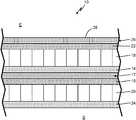
- FIG. 1is a simplified cross-sectional view showing the various layers of a composite panel.
- FIG. 2is a simplified cross-sectional view of a 3D woven face sheet belonging to the composite panel.
- the present inventionis directed to a composite panel, and more specifically, to a heated floor panel with a three-dimensional (3D) woven face sheet.
- the face sheetincludes three orthogonal fiber components in multiple layers. Binding “z-fibers” interlock the other layers to prevent delamination.
- the panelfurther includes a metallic core layer above the heating element, which, along with the z-fibers, improves thermal conductivity to the panel surface.
- FIG. 1is a simplified cross-section of composite panel 10 .
- Panel 10includes heating layer 12 , adhesive layers 14 and 16 , honeycomb core layers 18 and 20 , structural layers 22 and 24 , and face sheet 26 .
- Surface 28 of face sheet 26represents the upper (external) surface of panel 10 .
- Panel 10is positioned over substrate S, and provides heat to environment E, which is located on a side of panel 10 opposite substrate S.
- Heating layer 12can include a thermoelectric heating element (not shown).
- the heating elementcan be a resistive heating element formed, for example, from a metallic material, Positive Temperature Control (PTC) ceramic, PTC polymer, or carbon allotrope material.
- PTCPositive Temperature Control
- the heating elementcan be arranged as an etched foil, wire, or printed-ink element. Other suitable heating elements are contemplated herein.
- Heating layer 12can be used to control the temperature of surface 28 of panel 10 , which can be installed, for example, in an aircraft cabin or cockpit. In certain embodiments, the heating element can extend across the entire area of heating layer 12 . In other embodiments, the heating element can be inset some distance from the edges of heating layer 12 in order to protect the element from fluid spills along or damage at the edges of panel 10 .
- Core layers 18 and 20provide impact resistance to panel 10 , and carry shear loads to stiffen floor panel 10 .
- Upper core layer 18can, in an exemplary embodiment, be a high-density honeycomb core formed from a metallic material, such as aluminum.
- Lower core layer 20can be formed from an expanded honeycomb polymer, such as aramids (e.g., Kevlar® or Nomex®), as well as an open-cell or closed-cell polymer foam.
- metallic upper core layer 18has greater thermal conductivity than polymer lower core layer 20 , which improves the heat transfer properties of panel 10 in the direction of surface 28 , where heating is desired.
- both core layers 18 and 20can be formed from the same material (e.g., metal or polymer), and such an arrangement will depend on factors such as weight limitations and panel heating/insulation requirements.
- Adhesive layers 14 and 16can be located between heating layer 12 and core layers 18 and 20 , respectively, to help secure the core structure about the heating layer.
- Adhesive layers 14 and 16can include film adhesives (e.g., epoxy) or a prepreg (composite fibers impregnated with a matrix material) having a high resin content. Additional and/or alternative adhesive layers can be positioned at other locations between or within layers to further solidify panel structure.
- Structural layers 22 and 24provide additional reinforcement to panel 10 .
- Structural layers 22 and 24can be a reinforced polymer, such as a carbon fiber or fiberglass impregnated with a resin system such as epoxy, polyurethane, phenolic, cyanate ester, bismaleimide, or other appropriate resins.
- a resin systemsuch as epoxy, polyurethane, phenolic, cyanate ester, bismaleimide, or other appropriate resins.
- Each of structural layers 22 and 24can include a single ply, or a plurality of plies, depending on, for example, the material chosen to form the structural layers, or the particular need for reinforcement. Additional and/or alternative structural layers can also be added in other embodiments.
- FIG. 2is a simplified cross-sectional view of face sheet 26 , shown for simplicity without the other layers of panel 10 .
- Face sheet 26provides structural support, and more specifically, impact strength to panel 10 on the side of panel 10 exposed to environment E, which can be, for example, an aircraft cabin, cockpit, or other compartment.
- environment Ecan be, for example, an aircraft cabin, cockpit, or other compartment.
- face sheet 26is structured as a 3D woven composite, having fiber components in three, generally orthogonal axes (x, y, z) as labeled in FIG. 2 .
- Face sheet 26includes a plurality of warp layers 30 extending along the x-axis.
- Each warp layer 30can be formed from a single warp fiber 32 , or from a number of warp fibers 32 arranged, for example, as a bundle of fibers (e.g., yarn).
- Weft layers 34extend along the y-axis in an alternating fashion with warp layers 30 .
- Weft layers 34can also be formed from one or more weft fibers 36 .
- Face sheet 26further includes at least one z-fiber 38 extending along the z-axis, which, as shown, is the thickness direction of face sheet 26 .
- one z-fiber 38extends from an uppermost weft layer 34 (relative to surface 28 ) along the plurality of weft layers 34 and crosses along the neighboring, lowermost weft layer 34 .
- a second z-fiber 38traverses the thickness of face sheet in the opposite direction, such that the two z-fibers 38 cross one another between individual weft columns 40 (i.e. “stacks” of individual weft layers 34 in the thickness direction), thus interlocking and securing weft layers 34 through the thickness of face sheet 26 .
- the weft, warp, and z-fiber componentscan be arranged differently, for example, in a ply-to-ply interlock architecture, or a through-thickness angle interlock architecture, depending on such factors as manufacturing capabilities, fiber materials, or desired in-plane and/or out-of-plane mechanical properties of face sheet 26 .
- the various fibers of face sheet 26can be formed from different materials depending on the composite scale of the face sheet.
- warp fibers 32 and weft fibers 36can be formed from glass, aramid, carbon, or metallic materials
- z-fibers 38can be formed from steel nanotubes or carbon nanotubes.
- warp fibers 32 , weft fibers 36 , and z-fibers 38can be formed from glass, aramid, or metallic materials.
- Other suitable high-strength, high-stiffness, and low-density materialsare contemplated herein.
- Face sheet 26can further be reinforced with polymer matrix 42 , represented in FIG.
- Matrix 42can be formed from a thermoplastic, such as polyether ether ketone (PEEK) or polycarbonate, or a thermoset, such as epoxy or phenolic resin.
- a thermoplasticsuch as polyether ether ketone (PEEK) or polycarbonate
- a thermosetsuch as epoxy or phenolic resin.
- the 3D woven structure and matrix 42give face sheet 26 improved damage tolerance over 2D structures.
- Z-fibers 38secure weft layers 34 along the thickness direction to help prevent separation of individual warp and weft layers. Further, z-fibers 38 can absorb energy in the thickness direction and facilitate impact force dissipation.
- Matrix 42helps bind the fiber components and maintain the shape of face sheet 26 . Matrix 42 also helps transfer loads to the fiber components.
- Face sheet 26also has improved thermal conductivity due to the presence of z-fibers 38 , which can be formed from relatively thermally conductive materials (e.g. carbon, metals, etc.) when compared to matrix 42 , and help transfer heat radiating upward (along the z-axis) from heating layer 12 to surface 28 and environment E. The thickness of face sheet 26 can be varied to further optimize its thermal and mechanical properties.
- the disclosed panelis highly impact resistant due to the 3D woven structure of face sheet 10 .
- the combination of face sheet 26 and metallic upper core layer 18also offer improved thermal conductivity, which lead to reduced power requirements for the heating element(s) within heating layer 12 .
- the high strength to weight ratio of panel 10makes it ideal for aerospace applications, but it can also be used in maritime, railroad, and automotive applications, as well as the construction industry.
- a composite panel suitable for heating an environmentincludes a face sheet having a 3D woven structure and abutting the environment, and a first core layer positioned on a side of the face sheet opposite the environment.
- the 3D woven structureincludes at least one z-fiber extending in a first direction, the first direction representing a thickness of the face sheet.
- the woven structurefurther includes a plurality of weft layers, each having a weft fiber extending in a second direction, and a warp layer disposed between the plurality of weft layers, the warp layer having a warp fiber extending in a third direction.
- the z-fiberextends along the plurality of weft layers across a full extent of the 3d woven structure in the first direction.
- the panel of the preceding paragraphcan optionally include, additionally and/or alternatively, any one or more of the following features, configurations and/or additional components:
- the first core layercan include a high-density honeycomb core formed from aluminum.
- any of the above panelscan further include a second core layer disposed on a side of the first core layer opposite the face sheet.
- the second core layercan include a polymer foam or a polymer honeycomb.
- the at least one z-fibercan be formed from a glass, aramid, or metallic material.
- the at least one z-fibercan include a nanostructure formed from steel nanotubes or carbon nanotubes.
- the at least one z-fibercan include a plurality of z-fibers.
- the weft fibercan be formed from a glass, aramid, or metallic material.
- the warp fibercan be formed from a glass, aramid, or metallic material.
- the face sheetcan further include a matrix formed from a thermoset or thermoplastic material.
- the z-fibercan have a higher thermal conductivity than the matrix.
- the first, second, and third directionsare orthogonal to one another.
- any of the above panelscan further include a first reinforcing layer abutting the first core layer, and a second reinforcing layer abutting the second core layer.
- the environmentcan be an aircraft compartment.
- a method of forming a composite panel suitable for heating an environmentincludes positioning a face sheet having a 3D woven structure in communication with the environment, and positioning a first core layer on a side of the face sheet opposite the environment.
- the 3D woven structureincludes at least one z-fiber extending in a first direction, the first direction representing a thickness of the face sheet.
- the woven structurefurther includes a plurality of weft layers, each having a weft fiber extending in a second direction, and a warp layer disposed between the plurality of weft layers, the warp layer having a warp fiber extending in a third direction.
- the z-fiberextends along the plurality of weft layers across a full extent of the 3D woven structure in the first direction.
- the method of the preceding paragraphcan optionally include, additionally and/or alternatively, any one or more of the following features, configurations and/or additional components:
- the first core layercan include a high-density honeycomb core formed from aluminum.
- the at least one z-fibercan be formed from a glass, aramid, or metallic material.
- the at least one z-fibercan include a nanostructure formed from steel nanotubes or carbon nanotubes.
- the weft fiber and the warp fibercan be formed from a glass, aramid, or metallic material.
- the face sheetfurther can include a matrix formed from a thermoset or thermoplastic material.
Landscapes
- Engineering & Computer Science (AREA)
- Chemical & Material Sciences (AREA)
- Textile Engineering (AREA)
- Mechanical Engineering (AREA)
- Combustion & Propulsion (AREA)
- Aviation & Aerospace Engineering (AREA)
- Physics & Mathematics (AREA)
- Thermal Sciences (AREA)
- General Engineering & Computer Science (AREA)
- Inorganic Chemistry (AREA)
- Chemical Kinetics & Catalysis (AREA)
- Health & Medical Sciences (AREA)
- Medicinal Chemistry (AREA)
- Polymers & Plastics (AREA)
- Organic Chemistry (AREA)
- Manufacturing & Machinery (AREA)
- Materials Engineering (AREA)
- Laminated Bodies (AREA)
- Woven Fabrics (AREA)
Abstract
Description
Claims (16)
Applications Claiming Priority (2)
| Application Number | Priority Date | Filing Date | Title |
|---|---|---|---|
| IN201841023912 | 2018-06-27 | ||
| IN201841023912 | 2018-06-27 |
Publications (2)
| Publication Number | Publication Date |
|---|---|
| US20200001966A1 US20200001966A1 (en) | 2020-01-02 |
| US11040765B2true US11040765B2 (en) | 2021-06-22 |
Family
ID=67070747
Family Applications (1)
| Application Number | Title | Priority Date | Filing Date |
|---|---|---|---|
| US16/135,265Active2038-12-28US11040765B2 (en) | 2018-06-27 | 2018-09-19 | Advanced composite heated floor panel |
Country Status (6)
| Country | Link |
|---|---|
| US (1) | US11040765B2 (en) |
| EP (1) | EP3587097B1 (en) |
| JP (1) | JP7265425B2 (en) |
| BR (1) | BR102019012609A2 (en) |
| CA (1) | CA3048075A1 (en) |
| ES (1) | ES2905714T3 (en) |
Families Citing this family (6)
| Publication number | Priority date | Publication date | Assignee | Title |
|---|---|---|---|---|
| US11376811B2 (en) | 2018-07-03 | 2022-07-05 | Goodrich Corporation | Impact and knife cut resistant pre-impregnated woven fabric for aircraft heated floor panels |
| US10875623B2 (en)* | 2018-07-03 | 2020-12-29 | Goodrich Corporation | High temperature thermoplastic pre-impregnated structure for aircraft heated floor panel |
| DE102018009218B4 (en)* | 2018-11-23 | 2025-04-10 | Airbus Operations Gmbh | Cladding element with heating layer in sandwich construction |
| CN214220433U (en)* | 2019-10-15 | 2021-09-17 | 龙钟江 | Polyurethane composite floor |
| NL2032299B1 (en)* | 2021-10-08 | 2023-06-16 | Calor Invest B V | Method for applying an electric heating foil, as well as a building fitted with the heating foil |
| US20240397583A1 (en)* | 2021-10-08 | 2024-11-28 | Calor Investments B.V. | Method for applying an electric heating foil, as well as a building provided with the heating foil |
Citations (17)
| Publication number | Priority date | Publication date | Assignee | Title |
|---|---|---|---|---|
| WO1995026877A1 (en) | 1994-04-01 | 1995-10-12 | Hexcel Corporation | Thermally conductive non-metallic honeycomb and process |
| US6743497B2 (en)* | 2000-06-27 | 2004-06-01 | Sakura Rubber Co., Ltd. | Honeycomb sandwich panel |
| US20070054087A1 (en)* | 2004-09-01 | 2007-03-08 | Hexcel Corporation | Aircraft floor panels using edge coated honeycomb |
| US20080031604A1 (en)* | 2004-10-05 | 2008-02-07 | Kerschbaum, Wolfgang | Heating Device |
| US7731046B2 (en) | 2001-04-06 | 2010-06-08 | Ebert Composites Corporation | Composite sandwich panel and method of making same |
| US7988809B2 (en) | 2004-09-01 | 2011-08-02 | Hexcel Corporation | Aircraft floor and interior panels using edge coated honeycomb |
| US8752279B2 (en) | 2007-01-04 | 2014-06-17 | Goodrich Corporation | Methods of protecting an aircraft component from ice formation |
| US8834985B2 (en) | 2012-11-30 | 2014-09-16 | Global Ip Holdings, Llc | Sandwich-type composite component having imprinted 3-D structures which provide at least one pattern at an outer surface of the component |
| US8926880B2 (en) | 2008-04-15 | 2015-01-06 | Airbus Operations Gmbh | Method for manufacturing a core composite provided with cover layers on both sides as well as a core composite |
| US9493894B2 (en) | 2013-06-12 | 2016-11-15 | Spectra Aerostructures of South Carolina, Inc. | Interior panel for vehicle |
| US20160340020A1 (en) | 2015-05-21 | 2016-11-24 | Goodrich Corporation | Aircraft floor panel |
| US20160361889A1 (en) | 2014-02-27 | 2016-12-15 | B/E Aerospace Inc. | Composite sandwich panel with differential resin layers |
| US9593917B2 (en) | 2006-09-06 | 2017-03-14 | Polyone Corporation | Composite laminate and method of manufacture |
| WO2017100900A1 (en) | 2015-12-15 | 2017-06-22 | Farid Taheri | Method of making a 3d glass fiber metal laminate and 3d laminate structural panel |
| WO2017114416A1 (en) | 2015-12-31 | 2017-07-06 | Byd Company Limited | Composite honeycomb sandwich board and method for preparing the same |
| US9914522B2 (en) | 2014-10-29 | 2018-03-13 | Airbus Operations Gmbh | Floor panel for an aircraft, and an aircraft comprising such a floor panel |
| CN108004637A (en) | 2018-01-12 | 2018-05-08 | 东华大学 | A kind of 3-dimensional multi-layered interstitital texture composite electrothermal material and preparation method thereof |
Family Cites Families (4)
| Publication number | Priority date | Publication date | Assignee | Title |
|---|---|---|---|---|
| DE19918736C2 (en)* | 1999-04-24 | 2002-12-05 | Airbus Gmbh | Panel component, in particular for a floor panel in an aircraft |
| JP4126978B2 (en)* | 2001-07-06 | 2008-07-30 | 東レ株式会社 | Preform, FRP comprising the same, and method for producing FRP |
| JP4639549B2 (en)* | 2001-08-07 | 2011-02-23 | 東レ株式会社 | Manufacturing method of FRP |
| JP5915901B2 (en)* | 2012-04-25 | 2016-05-11 | 株式会社ミツウマ | Conductive three-dimensional fiber structure and method for producing the same |
- 2018
- 2018-09-19USUS16/135,265patent/US11040765B2/enactiveActive
- 2019
- 2019-06-13JPJP2019109996Apatent/JP7265425B2/enactiveActive
- 2019-06-18BRBR102019012609Apatent/BR102019012609A2/ennot_activeApplication Discontinuation
- 2019-06-26CACA3048075Apatent/CA3048075A1/enactivePending
- 2019-06-26ESES19182554Tpatent/ES2905714T3/enactiveActive
- 2019-06-26EPEP19182554.6Apatent/EP3587097B1/enactiveActive
Patent Citations (17)
| Publication number | Priority date | Publication date | Assignee | Title |
|---|---|---|---|---|
| WO1995026877A1 (en) | 1994-04-01 | 1995-10-12 | Hexcel Corporation | Thermally conductive non-metallic honeycomb and process |
| US6743497B2 (en)* | 2000-06-27 | 2004-06-01 | Sakura Rubber Co., Ltd. | Honeycomb sandwich panel |
| US7731046B2 (en) | 2001-04-06 | 2010-06-08 | Ebert Composites Corporation | Composite sandwich panel and method of making same |
| US20070054087A1 (en)* | 2004-09-01 | 2007-03-08 | Hexcel Corporation | Aircraft floor panels using edge coated honeycomb |
| US7988809B2 (en) | 2004-09-01 | 2011-08-02 | Hexcel Corporation | Aircraft floor and interior panels using edge coated honeycomb |
| US20080031604A1 (en)* | 2004-10-05 | 2008-02-07 | Kerschbaum, Wolfgang | Heating Device |
| US9593917B2 (en) | 2006-09-06 | 2017-03-14 | Polyone Corporation | Composite laminate and method of manufacture |
| US8752279B2 (en) | 2007-01-04 | 2014-06-17 | Goodrich Corporation | Methods of protecting an aircraft component from ice formation |
| US8926880B2 (en) | 2008-04-15 | 2015-01-06 | Airbus Operations Gmbh | Method for manufacturing a core composite provided with cover layers on both sides as well as a core composite |
| US8834985B2 (en) | 2012-11-30 | 2014-09-16 | Global Ip Holdings, Llc | Sandwich-type composite component having imprinted 3-D structures which provide at least one pattern at an outer surface of the component |
| US9493894B2 (en) | 2013-06-12 | 2016-11-15 | Spectra Aerostructures of South Carolina, Inc. | Interior panel for vehicle |
| US20160361889A1 (en) | 2014-02-27 | 2016-12-15 | B/E Aerospace Inc. | Composite sandwich panel with differential resin layers |
| US9914522B2 (en) | 2014-10-29 | 2018-03-13 | Airbus Operations Gmbh | Floor panel for an aircraft, and an aircraft comprising such a floor panel |
| US20160340020A1 (en) | 2015-05-21 | 2016-11-24 | Goodrich Corporation | Aircraft floor panel |
| WO2017100900A1 (en) | 2015-12-15 | 2017-06-22 | Farid Taheri | Method of making a 3d glass fiber metal laminate and 3d laminate structural panel |
| WO2017114416A1 (en) | 2015-12-31 | 2017-07-06 | Byd Company Limited | Composite honeycomb sandwich board and method for preparing the same |
| CN108004637A (en) | 2018-01-12 | 2018-05-08 | 东华大学 | A kind of 3-dimensional multi-layered interstitital texture composite electrothermal material and preparation method thereof |
Non-Patent Citations (4)
| Title |
|---|
| Communication Pursuant to Article 94(3) EPC for EP Application No. 19182554.6, dated Oct. 1, 2020, 4 pages. |
| Extended European Search Report for EP Application No. 19182554.6, dated Nov. 14, 2019, 7 pages. |
| J. Schuster et al, "Thermal Conductivities of Three-Dimensionally Woven Fabric Composites", from Composites Science and Technology 68, pp. 2085-2091, 2008. |
| Machine translation of CN 108004637 (Year: 2018).* |
Also Published As
| Publication number | Publication date |
|---|---|
| JP2020001387A (en) | 2020-01-09 |
| US20200001966A1 (en) | 2020-01-02 |
| JP7265425B2 (en) | 2023-04-26 |
| EP3587097B1 (en) | 2022-01-19 |
| CA3048075A1 (en) | 2019-12-27 |
| EP3587097A1 (en) | 2020-01-01 |
| BR102019012609A2 (en) | 2020-01-14 |
| ES2905714T3 (en) | 2022-04-11 |
Similar Documents
| Publication | Publication Date | Title |
|---|---|---|
| US11040765B2 (en) | Advanced composite heated floor panel | |
| Xiong et al. | Sandwich structures with prismatic and foam cores: a review | |
| US10899427B2 (en) | Heated floor panel with impact layer | |
| US10391734B2 (en) | Composite sandwich panel with differential resin layers | |
| US11878500B2 (en) | Impact and knife cut resistant pre-impregnated woven fabric for aircraft heated floor panels | |
| AU2005289392B2 (en) | Thin ply laminates | |
| EP1871662B1 (en) | Integrated aircraft structural floor | |
| CN102892572B (en) | Composite beam chord between stiffener plates and related manufacturing method | |
| US10780678B2 (en) | Composite sandwich structure | |
| EP3476586B1 (en) | Method for reinforcing a composite sandwich panel | |
| WO2015130985A1 (en) | Composite sandwich panel having curable composite skins with asymmetrical resin distributions | |
| BR112014002438B1 (en) | molybdenum composite hybrid laminate and method of forming a molybdenum composite hybrid laminate | |
| EP3590701B1 (en) | High temperature thermoplastic pre-impregnated structure for aircraft heated floor panel | |
| US12257817B2 (en) | Composite panel structure and method of manufacturing | |
| US20250128482A1 (en) | High thermal conductivity composite material stitched with pitch-based carbon fiber, and method for manufacturing the same | |
| US20240269955A1 (en) | Foam sheeting for honeycomb core walls, to replace paper and metal honeycomb and machined foam core in sandwich structure | |
| EP3495135A1 (en) | Asymmetric core sandwich structure for heated floor panels | |
| EP3592107B1 (en) | Heated floor panels | |
| Gour et al. | Implementation Of Aircraft Wardrobe Using Honeycomb Composite Over Aluminium. A Review | |
| US20250128500A1 (en) | High thermal conductivity composite material comprising pan-based carbon fiber and patterned graphite sheet and stitched with pitch-based carbon fiber, and method for manufacturing the same | |
| KR20200024633A (en) | Fiber reinforced composite material with uniform surface |
Legal Events
| Date | Code | Title | Description |
|---|---|---|---|
| FEPP | Fee payment procedure | Free format text:ENTITY STATUS SET TO UNDISCOUNTED (ORIGINAL EVENT CODE: BIG.); ENTITY STATUS OF PATENT OWNER: LARGE ENTITY | |
| AS | Assignment | Owner name:GOODRICH CORPORATION, NORTH CAROLINA Free format text:ASSIGNMENT OF ASSIGNORS INTEREST;ASSIGNOR:GOODRICH AEROSPACE SERVICES PRIVATE LIMITED;REEL/FRAME:048015/0991 Effective date:20181114 Owner name:GOODRICH AEROSPACE SERVICES PRIVATE LIMITED, INDIA Free format text:ASSIGNMENT OF ASSIGNORS INTEREST;ASSIGNORS:KRISHNAPPA, ARUNA KUMAR HULUVANGALA;MAHAPATRA, GURU PRASAD;REEL/FRAME:048015/0259 Effective date:20180627 | |
| STPP | Information on status: patent application and granting procedure in general | Free format text:NON FINAL ACTION MAILED | |
| STPP | Information on status: patent application and granting procedure in general | Free format text:RESPONSE TO NON-FINAL OFFICE ACTION ENTERED AND FORWARDED TO EXAMINER | |
| STPP | Information on status: patent application and granting procedure in general | Free format text:AWAITING TC RESP, ISSUE FEE PAYMENT RECEIVED | |
| STPP | Information on status: patent application and granting procedure in general | Free format text:PUBLICATIONS -- ISSUE FEE PAYMENT VERIFIED | |
| STCF | Information on status: patent grant | Free format text:PATENTED CASE | |
| STPP | Information on status: patent application and granting procedure in general | Free format text:AWAITING TC RESP., ISSUE FEE NOT PAID | |
| STPP | Information on status: patent application and granting procedure in general | Free format text:DOCKETED NEW CASE - READY FOR EXAMINATION | |
| STPP | Information on status: patent application and granting procedure in general | Free format text:NON FINAL ACTION MAILED | |
| STPP | Information on status: patent application and granting procedure in general | Free format text:RESPONSE TO NON-FINAL OFFICE ACTION ENTERED AND FORWARDED TO EXAMINER | |
| STPP | Information on status: patent application and granting procedure in general | Free format text:NOTICE OF ALLOWANCE MAILED -- APPLICATION RECEIVED IN OFFICE OF PUBLICATIONS | |
| STPP | Information on status: patent application and granting procedure in general | Free format text:PUBLICATIONS -- ISSUE FEE PAYMENT RECEIVED | |
| STPP | Information on status: patent application and granting procedure in general | Free format text:PUBLICATIONS -- ISSUE FEE PAYMENT VERIFIED | |
| STCF | Information on status: patent grant | Free format text:PATENTED CASE | |
| MAFP | Maintenance fee payment | Free format text:PAYMENT OF MAINTENANCE FEE, 4TH YEAR, LARGE ENTITY (ORIGINAL EVENT CODE: M1551); ENTITY STATUS OF PATENT OWNER: LARGE ENTITY Year of fee payment:4 |