US11040503B2 - Apparatus for manufacturing composite airfoils - Google Patents
Apparatus for manufacturing composite airfoilsDownload PDFInfo
- Publication number
- US11040503B2 US11040503B2US15/819,042US201715819042AUS11040503B2US 11040503 B2US11040503 B2US 11040503B2US 201715819042 AUS201715819042 AUS 201715819042AUS 11040503 B2US11040503 B2US 11040503B2
- Authority
- US
- United States
- Prior art keywords
- axis
- machine heads
- along
- composite component
- mold
- Prior art date
- Legal status (The legal status is an assumption and is not a legal conclusion. Google has not performed a legal analysis and makes no representation as to the accuracy of the status listed.)
- Expired - Fee Related, expires
Links
Images


Classifications
- B—PERFORMING OPERATIONS; TRANSPORTING
- B29—WORKING OF PLASTICS; WORKING OF SUBSTANCES IN A PLASTIC STATE IN GENERAL
- B29C—SHAPING OR JOINING OF PLASTICS; SHAPING OF MATERIAL IN A PLASTIC STATE, NOT OTHERWISE PROVIDED FOR; AFTER-TREATMENT OF THE SHAPED PRODUCTS, e.g. REPAIRING
- B29C70/00—Shaping composites, i.e. plastics material comprising reinforcements, fillers or preformed parts, e.g. inserts
- B29C70/04—Shaping composites, i.e. plastics material comprising reinforcements, fillers or preformed parts, e.g. inserts comprising reinforcements only, e.g. self-reinforcing plastics
- B29C70/28—Shaping operations therefor
- B29C70/54—Component parts, details or accessories; Auxiliary operations, e.g. feeding or storage of prepregs or SMC after impregnation or during ageing
- B—PERFORMING OPERATIONS; TRANSPORTING
- B29—WORKING OF PLASTICS; WORKING OF SUBSTANCES IN A PLASTIC STATE IN GENERAL
- B29C—SHAPING OR JOINING OF PLASTICS; SHAPING OF MATERIAL IN A PLASTIC STATE, NOT OTHERWISE PROVIDED FOR; AFTER-TREATMENT OF THE SHAPED PRODUCTS, e.g. REPAIRING
- B29C33/00—Moulds or cores; Details thereof or accessories therefor
- B29C33/34—Moulds or cores; Details thereof or accessories therefor movable, e.g. to or from the moulding station
- B—PERFORMING OPERATIONS; TRANSPORTING
- B29—WORKING OF PLASTICS; WORKING OF SUBSTANCES IN A PLASTIC STATE IN GENERAL
- B29C—SHAPING OR JOINING OF PLASTICS; SHAPING OF MATERIAL IN A PLASTIC STATE, NOT OTHERWISE PROVIDED FOR; AFTER-TREATMENT OF THE SHAPED PRODUCTS, e.g. REPAIRING
- B29C69/00—Combinations of shaping techniques not provided for in a single one of main groups B29C39/00 - B29C67/00, e.g. associations of moulding and joining techniques; Apparatus therefore
- B29C69/001—Combinations of shaping techniques not provided for in a single one of main groups B29C39/00 - B29C67/00, e.g. associations of moulding and joining techniques; Apparatus therefore a shaping technique combined with cutting, e.g. in parts or slices combined with rearranging and joining the cut parts
- B—PERFORMING OPERATIONS; TRANSPORTING
- B29—WORKING OF PLASTICS; WORKING OF SUBSTANCES IN A PLASTIC STATE IN GENERAL
- B29C—SHAPING OR JOINING OF PLASTICS; SHAPING OF MATERIAL IN A PLASTIC STATE, NOT OTHERWISE PROVIDED FOR; AFTER-TREATMENT OF THE SHAPED PRODUCTS, e.g. REPAIRING
- B29C70/00—Shaping composites, i.e. plastics material comprising reinforcements, fillers or preformed parts, e.g. inserts
- B29C70/04—Shaping composites, i.e. plastics material comprising reinforcements, fillers or preformed parts, e.g. inserts comprising reinforcements only, e.g. self-reinforcing plastics
- B29C70/28—Shaping operations therefor
- B29C70/30—Shaping by lay-up, i.e. applying fibres, tape or broadsheet on a mould, former or core; Shaping by spray-up, i.e. spraying of fibres on a mould, former or core
- B29C70/38—Automated lay-up, e.g. using robots, laying filaments according to predetermined patterns
- B29C70/382—Automated fiber placement [AFP]
- B—PERFORMING OPERATIONS; TRANSPORTING
- B29—WORKING OF PLASTICS; WORKING OF SUBSTANCES IN A PLASTIC STATE IN GENERAL
- B29C—SHAPING OR JOINING OF PLASTICS; SHAPING OF MATERIAL IN A PLASTIC STATE, NOT OTHERWISE PROVIDED FOR; AFTER-TREATMENT OF THE SHAPED PRODUCTS, e.g. REPAIRING
- B29C70/00—Shaping composites, i.e. plastics material comprising reinforcements, fillers or preformed parts, e.g. inserts
- B29C70/04—Shaping composites, i.e. plastics material comprising reinforcements, fillers or preformed parts, e.g. inserts comprising reinforcements only, e.g. self-reinforcing plastics
- B29C70/28—Shaping operations therefor
- B29C70/30—Shaping by lay-up, i.e. applying fibres, tape or broadsheet on a mould, former or core; Shaping by spray-up, i.e. spraying of fibres on a mould, former or core
- B29C70/38—Automated lay-up, e.g. using robots, laying filaments according to predetermined patterns
- B29C70/386—Automated tape laying [ATL]
- B—PERFORMING OPERATIONS; TRANSPORTING
- B29—WORKING OF PLASTICS; WORKING OF SUBSTANCES IN A PLASTIC STATE IN GENERAL
- B29D—PRODUCING PARTICULAR ARTICLES FROM PLASTICS OR FROM SUBSTANCES IN A PLASTIC STATE
- B29D99/00—Subject matter not provided for in other groups of this subclass
- B29D99/0025—Producing blades or the like, e.g. blades for turbines, propellers, or wings
- B29D99/0028—Producing blades or the like, e.g. blades for turbines, propellers, or wings hollow blades
- B—PERFORMING OPERATIONS; TRANSPORTING
- B33—ADDITIVE MANUFACTURING TECHNOLOGY
- B33Y—ADDITIVE MANUFACTURING, i.e. MANUFACTURING OF THREE-DIMENSIONAL [3-D] OBJECTS BY ADDITIVE DEPOSITION, ADDITIVE AGGLOMERATION OR ADDITIVE LAYERING, e.g. BY 3-D PRINTING, STEREOLITHOGRAPHY OR SELECTIVE LASER SINTERING
- B33Y80/00—Products made by additive manufacturing
- B—PERFORMING OPERATIONS; TRANSPORTING
- B29—WORKING OF PLASTICS; WORKING OF SUBSTANCES IN A PLASTIC STATE IN GENERAL
- B29C—SHAPING OR JOINING OF PLASTICS; SHAPING OF MATERIAL IN A PLASTIC STATE, NOT OTHERWISE PROVIDED FOR; AFTER-TREATMENT OF THE SHAPED PRODUCTS, e.g. REPAIRING
- B29C64/00—Additive manufacturing, i.e. manufacturing of three-dimensional [3D] objects by additive deposition, additive agglomeration or additive layering, e.g. by 3D printing, stereolithography or selective laser sintering
- B29C64/20—Apparatus for additive manufacturing; Details thereof or accessories therefor
- B29C64/205—Means for applying layers
- B29C64/209—Heads; Nozzles
- B—PERFORMING OPERATIONS; TRANSPORTING
- B29—WORKING OF PLASTICS; WORKING OF SUBSTANCES IN A PLASTIC STATE IN GENERAL
- B29L—INDEXING SCHEME ASSOCIATED WITH SUBCLASS B29C, RELATING TO PARTICULAR ARTICLES
- B29L2031/00—Other particular articles
- B29L2031/08—Blades for rotors, stators, fans, turbines or the like, e.g. screw propellers
- B29L2031/082—Blades, e.g. for helicopters
- B29L2031/085—Wind turbine blades
- B—PERFORMING OPERATIONS; TRANSPORTING
- B33—ADDITIVE MANUFACTURING TECHNOLOGY
- B33Y—ADDITIVE MANUFACTURING, i.e. MANUFACTURING OF THREE-DIMENSIONAL [3-D] OBJECTS BY ADDITIVE DEPOSITION, ADDITIVE AGGLOMERATION OR ADDITIVE LAYERING, e.g. BY 3-D PRINTING, STEREOLITHOGRAPHY OR SELECTIVE LASER SINTERING
- B33Y30/00—Apparatus for additive manufacturing; Details thereof or accessories therefor
- F—MECHANICAL ENGINEERING; LIGHTING; HEATING; WEAPONS; BLASTING
- F03—MACHINES OR ENGINES FOR LIQUIDS; WIND, SPRING, OR WEIGHT MOTORS; PRODUCING MECHANICAL POWER OR A REACTIVE PROPULSIVE THRUST, NOT OTHERWISE PROVIDED FOR
- F03D—WIND MOTORS
- F03D1/00—Wind motors with rotation axis substantially parallel to the air flow entering the rotor
- F03D1/06—Rotors
- F03D1/065—Rotors characterised by their construction elements
- F03D1/0675—Rotors characterised by their construction elements of the blades
- F—MECHANICAL ENGINEERING; LIGHTING; HEATING; WEAPONS; BLASTING
- F05—INDEXING SCHEMES RELATING TO ENGINES OR PUMPS IN VARIOUS SUBCLASSES OF CLASSES F01-F04
- F05B—INDEXING SCHEME RELATING TO WIND, SPRING, WEIGHT, INERTIA OR LIKE MOTORS, TO MACHINES OR ENGINES FOR LIQUIDS COVERED BY SUBCLASSES F03B, F03D AND F03G
- F05B2230/00—Manufacture
- F05B2230/30—Manufacture with deposition of material
- F—MECHANICAL ENGINEERING; LIGHTING; HEATING; WEAPONS; BLASTING
- F05—INDEXING SCHEMES RELATING TO ENGINES OR PUMPS IN VARIOUS SUBCLASSES OF CLASSES F01-F04
- F05B—INDEXING SCHEME RELATING TO WIND, SPRING, WEIGHT, INERTIA OR LIKE MOTORS, TO MACHINES OR ENGINES FOR LIQUIDS COVERED BY SUBCLASSES F03B, F03D AND F03G
- F05B2280/00—Materials; Properties thereof
- F05B2280/60—Properties or characteristics given to material by treatment or manufacturing
- F05B2280/6003—Composites; e.g. fibre-reinforced
- Y—GENERAL TAGGING OF NEW TECHNOLOGICAL DEVELOPMENTS; GENERAL TAGGING OF CROSS-SECTIONAL TECHNOLOGIES SPANNING OVER SEVERAL SECTIONS OF THE IPC; TECHNICAL SUBJECTS COVERED BY FORMER USPC CROSS-REFERENCE ART COLLECTIONS [XRACs] AND DIGESTS
- Y02—TECHNOLOGIES OR APPLICATIONS FOR MITIGATION OR ADAPTATION AGAINST CLIMATE CHANGE
- Y02E—REDUCTION OF GREENHOUSE GAS [GHG] EMISSIONS, RELATED TO ENERGY GENERATION, TRANSMISSION OR DISTRIBUTION
- Y02E10/00—Energy generation through renewable energy sources
- Y02E10/70—Wind energy
- Y02E10/72—Wind turbines with rotation axis in wind direction
- Y—GENERAL TAGGING OF NEW TECHNOLOGICAL DEVELOPMENTS; GENERAL TAGGING OF CROSS-SECTIONAL TECHNOLOGIES SPANNING OVER SEVERAL SECTIONS OF THE IPC; TECHNICAL SUBJECTS COVERED BY FORMER USPC CROSS-REFERENCE ART COLLECTIONS [XRACs] AND DIGESTS
- Y02—TECHNOLOGIES OR APPLICATIONS FOR MITIGATION OR ADAPTATION AGAINST CLIMATE CHANGE
- Y02P—CLIMATE CHANGE MITIGATION TECHNOLOGIES IN THE PRODUCTION OR PROCESSING OF GOODS
- Y02P70/00—Climate change mitigation technologies in the production process for final industrial or consumer products
- Y02P70/50—Manufacturing or production processes characterised by the final manufactured product
Definitions
- the present disclosurerelates in general to methods and apparatuses of manufacturing composite structures.
- the present disclosurerelates more specifically to methods and apparatuses for manufacturing composite airfoils.
- Wind poweris considered one of the cleanest, most environmentally friendly energy sources presently available, and wind turbines have gained increased attention in this regard.
- a modern wind turbinetypically includes a tower, a generator, a gearbox, a nacelle, and one or more rotor blades.
- the rotor bladescapture kinetic energy of wind using known foil principles.
- the rotor bladestransmit the kinetic energy in the form of rotational energy so as to turn a shaft coupling the rotor blades to a gearbox, or if a gearbox is not used, directly to the generator.
- the generatorthen converts the mechanical energy to electrical energy that may be deployed to a utility grid.
- the rotor bladesgenerally include a suction side shell and a pressure side shell typically formed using molding processes that are bonded together at bond lines along the leading and trailing edges of the blade.
- the pressure and suction shellsare relatively lightweight and have structural properties (e.g., stiffness, buckling resistance and strength) which are not configured to withstand the bending moments and other loads exerted on the rotor blade during operation.
- the body shellis typically reinforced using one or more structural components (e.g. opposing spar caps with a shear web configured therebetween) that engage the inner pressure and suction side surfaces of the shell halves.
- the spar capsare typically constructed of various materials, including but not limited to glass fiber laminate composites and/or carbon fiber laminate composites.
- the shell of the rotor bladeis generally built around the spar caps of the blade by stacking layers of fiber fabrics in a shell mold. The layers are then typically infused together, e.g. with a thermoset resin. Accordingly, conventional rotor blades generally have a sandwich panel configuration. As such, conventional blade manufacturing of large rotor blades involves high labor costs, slow through put, and low utilization of expensive mold tooling. Further, the blade molds can be expensive to customize.
- methods for manufacturing rotor bladesmay include forming the rotor blades in segments. The blade segments may then be assembled to form the rotor blade.
- some modern rotor bladessuch as those blades described in U.S. patent application Ser. No. 14/753,137 filed Jun. 29, 2015 and entitled “Modular Wind Turbine Rotor Blades and Methods of Assembling Same,” which is incorporated herein by reference in its entirety, have a modular panel configuration.
- the various blade components of the modular bladecan be constructed of varying materials based on the function and/or location of the blade component.
- the present disclosureis directed to an apparatus for manufacturing a composite component.
- the apparatusincludes a mold onto which the composite component is formed.
- the moldis disposed within a grid defined by a first axis and a second axis.
- the apparatusfurther includes a first frame assembly disposed above the mold, and a plurality of machine heads coupled to the first frame assembly within the grid in an adjacent arrangement along the first axis. At least one of the mold or the plurality of machine heads is moveable along the first axis, the second axis, or both. At least one of the machine heads of the plurality of machine heads is moveable independently of one another along a third axis.
- each machine headdefines a centerline axis at least partially along the third axis.
- a distance between each adjacent pair of centerline axes of the machine headscorresponds to a desired spacing of a structure of the composite component to be formed.
- the first axisis substantially parallel to a length of the composite component.
- the second axisis substantially parallel to a width of the composite component.
- the widthis generally perpendicular to the length of the composite component.
- the plurality of machine headsdefines a front head and a rear head along the first axis. At least one of the mold or the plurality of machine heads is moveable to dispose at least the front head along the first axis at or beyond the length of the composite component to be formed along a first direction. In one embodiment, at least one of the mold or the plurality of machine heads is moveable to dispose at least the rear head along the first axis at or beyond the length of the composite component to be formed along a second direction opposite of the first direction. In still another embodiment, the plurality of machine heads is arranged along the first axis at least approximately 50% or greater of the length of the composite component to be formed.
- the first axisis substantially parallel to a width of the composite component.
- the second axisis substantially parallel to a length of the composite component.
- the widthis generally perpendicular to the length of the composite component.
- the plurality of machine headsdefines a front head and a rear head along the first axis. At least one of the mold or the plurality of machine heads is moveable to dispose at least the front head along the first axis at or beyond the width of the composite component to be formed along a first direction. In one embodiment, at least one of the mold or the plurality of machine heads is moveable to dispose at least the rear head along the first axis at or beyond the width of the composite component to be formed along a second direction opposite of the first direction. In another embodiment, the plurality of machine heads is arranged along the first axis at least approximately 50% or greater of the width of the composite component to be formed.
- the plurality of machine headsis extended along the first axis equal to or greater than a length or a width of the composite component to be formed onto the mold.
- one or more of the plurality of machine headsis rotatable about a fourth axis independently of one another.
- a working end of the one or more machine headsis disposed at an angle relative to the grid, wherein the angle ranges from approximately 0 degrees to approximately 175 degrees.
- one or more of the plurality of machine headsis rotatable about a fifth axis. The fifth axis is generally perpendicular to the fourth axis and the second axis.
- the first frame assemblyincludes a first frame moveable along the first axis and a second frame moveably coupled to the first frame.
- the plurality of machine headsis moveably coupled to the second frame so as to move along at least one of the first axis, the second axis, or the third axis.
- the second framedefines a second plurality of machine heads moveably coupled to the second frame adjacent to the plurality of machine heads on an opposing face of the second frame.
- One or more of the second plurality of machine headsis moveable independently of one another along the third axis.
- the apparatusdefines a plurality of the first frame in adjacent arrangement. Each first frame is independently moveable on a base frame along the first axis.
- each of the plurality of machine headsdefines at least one of a material deposition tool defining at least one or more of an extruder, a filament dispensing head, a tape deposition head, a paste dispensing head, a liquid dispensing head, or one or more of a curing tool, a material conditioning tool, a material cutting tool, a material removal tool, or a vacuum tool, or combinations thereof.
- At least one or more of the plurality of machine headsis configured to dispense a material from a working end thereof at one or more flow rates, temperatures, and/or pressures independently of one or more other machine heads.
- one or more of the plurality of machine headsdeposits at least of one of varying materials, varying thicknesses, or varying cross-sectional shapes onto an outer skin of the rotor blade panel.
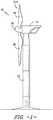
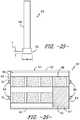
- FIG. 1illustrates a perspective view of one embodiment of a wind turbine according to an aspect of the present disclosure
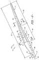
- FIG. 2illustrates a perspective view of one embodiment of a composite component according to an aspect of the present disclosure
- FIG. 3illustrates an exploded view of the composite component of FIG. 2 ;
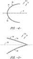
- FIG. 4illustrates a cross-sectional view of one embodiment of a leading edge segment of a composite component according to an aspect of the present disclosure
- FIG. 5illustrates a cross-sectional view of one embodiment of a trailing edge segment of a composite component according to an aspect of the present disclosure
- FIG. 6illustrates a cross-sectional view of the composite component of FIG. 2 according to an aspect of the present disclosure along line 6 - 6 ;
- FIG. 7illustrates a cross-sectional view of the composite component of FIG. 2 according to an aspect of the present disclosure along line 7 - 7 ;
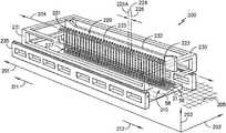
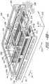
- FIG. 8Aillustrates a perspective view of one embodiment of an apparatus for manufacturing a composite component, such as the composite component generally illustrated in FIGS. 2-7 ;
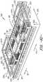
- FIG. 8Billustrates a perspective view of one embodiment of an apparatus for manufacturing a composite component, such as the composite component generally illustrated in FIGS. 2-7 ;
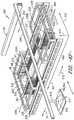
- FIG. 8Cillustrates a perspective view of one embodiment of an apparatus for manufacturing a composite component, such as the composite component generally illustrated in FIGS. 2-7 ;
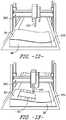
- FIG. 8Dillustrates a perspective view of the embodiment generally provided in FIG. 8C in an open position of the apparatus for manufacturing a composite component
- FIG. 8Eillustrates a side view of a portion of an embodiment of the apparatus generally provided in regard to FIGS. 8A-8F ;
- FIG. 8Fillustrates a perspective view of the embodiments of the apparatus generally provided in FIGS. 8C and 8D further depicting additional embodiments of the apparatus;
- FIG. 9Aillustrates a perspective view of another embodiment of an apparatus for manufacturing a composite component, such as the composite component generally illustrated in FIGS. 2-7 ;
- FIG. 9Billustrates a perspective view of another embodiment of an apparatus for manufacturing a composite component, such as the composite component generally illustrated in FIGS. 2-7
- FIG. 10illustrates a cross-sectional view of one embodiment of a mold of a composite component, particularly illustrating an outer skin placed in the mold with a plurality of grid structures printed thereto;
- FIG. 11illustrates a perspective view of one embodiment of a grid structure according to an aspect of the present disclosure
- FIG. 12illustrates a perspective view of one embodiment of a mold of a composite component with an apparatus for manufacturing the composite component positioned above the mold so as to print a grid structure thereto according to an aspect of the present disclosure
- FIG. 13illustrates a perspective view of one embodiment of a mold of a composite component with an apparatus for manufacturing a composite component positioned above the mold and printing an outline of a grid structure thereto according to an aspect of the present disclosure
- FIG. 14illustrates a perspective view of one embodiment of a mold of a composite component with an apparatus for manufacturing a composite component positioned above the mold and printing an outline of a grid structure thereto according to an aspect of the present disclosure
- FIG. 15illustrates a cross-sectional view of one embodiment of a first rib member of a grid structure according to an aspect of the present disclosure
- FIG. 16illustrates a cross-sectional view of another embodiment of a first rib member of a grid structure according to an aspect of the present disclosure
- FIG. 17illustrates a top view of one embodiment of a grid structure according to an aspect of the present disclosure
- FIG. 18illustrates a cross-sectional view of one embodiment of a first rib member and intersecting second rib members of a grid structure according to an aspect of the present disclosure
- FIG. 19illustrates a cross-sectional view of one embodiment of a second rib member of a grid structure according to an aspect of the present disclosure
- FIG. 20illustrates a top view of one embodiment of a grid structure according to an aspect of the present disclosure, particularly illustrating rib members of the grid structure arranged in a random pattern;
- FIG. 21illustrates a perspective view of another embodiment of a grid structure according to an aspect of the present disclosure, particularly illustrating rib members of the grid structure arranged in a random pattern;
- FIG. 22illustrates a graph of one embodiment of buckling load factor (y-axis) versus weight ratio (x-axis) of a grid structure according to an aspect of the present disclosure
- FIG. 23illustrates a partial, top view of one embodiment of a printed grid structure according to an aspect of the present disclosure, particularly illustrating a node of the grid structure;
- FIG. 24illustrates a partial, top view of one embodiment of a printed grid structure according to an aspect of the present disclosure, particularly illustrating a start printing location and an end printing location of the grid structure;
- FIG. 25illustrates an elevation view of one embodiment of a printed rib member of a grid structure according to an aspect of the present disclosure, particularly illustrating a base section of one of the rib members of the grid structure having a wider and thinner cross-section than the remainder of the rib member so as to improve bonding of the grid structure to the outer skins of the composite component;
- FIG. 26illustrates a top view of another embodiment of a grid structure according to an aspect of the present disclosure, particularly illustrating additional features printed to the grid structure;
- FIG. 27illustrates a cross-sectional view of one embodiment of a composite component having a printed grid structure arranged therein according to an aspect of the present disclosure, particularly illustrating alignment features printed to the grid structure for receiving the spar caps and shear web;
- FIG. 28illustrates a partial, cross-sectional view of the composite component of FIG. 25 , particularly illustrating additional features printed to the grid structure for controlling adhesive squeeze out;
- FIG. 29illustrates a cross-sectional view of one embodiment of a composite component having printed grid structures arranged therein according to an aspect of the present disclosure, particularly illustrating male and female panel alignment features printed to the grid structure;
- FIG. 30illustrates a top view of yet another embodiment of a grid structure according to an aspect of the present disclosure, particularly illustrating auxiliary features printed to the grid structure;
- FIG. 31illustrates a cross-sectional view of one embodiment of a composite component according to an aspect of the present disclosure, particularly illustrating a plurality of grid structures printed to inner surfaces of the rotor blade panel;
- FIG. 32illustrates a partial, cross-sectional view of the leading edge of the composite component of FIG. 29 , particularly illustrating a plurality of adhesive gaps.
- the present disclosureis directed to an apparatus and method for manufacturing a composite component, including structures thereof, using automated deposition of materials via technologies such as 3-D Printing, additive manufacturing, automated fiber deposition or tape deposition, as well as other techniques that utilize CNC control and multiple degrees of freedom to deposit material.
- the apparatusgenerally includes a mold onto which the composite component is formed.
- the moldis disposed within a grid defined by a first axis and a second axis generally perpendicular to the first axis.
- a plurality of machine headsis disposed within the grid in adjacent arrangement along the first axis.
- the plurality of machine headsis coupled to a first frame assembly.
- the mold, the plurality of machine heads, or both,is moveable along the first axis and the second axis.
- Each machine head of the plurality of machine headsis moveable independently of one another along a third axis.
- the embodiments of the apparatus and method shown and described hereinmay improve manufacturing cycle time efficiency, such as by enabling a relatively simple zig-zag, sinusoidal, or orthogonal motion to deposit composite component structures, such as onto a rotor blade panel formed onto a mold.
- the methods described hereinprovide many advantages not present in the prior art.
- the methods of the present disclosuremay provide the ability to easily customize composite component structures having various curvatures, aerodynamic characteristics, strengths, stiffness, etc.
- the printed or formed structures of the present disclosurecan be designed to match the stiffness and/or buckling resistance of existing sandwich panels for composite components.
- composite components defining the exemplary rotor blades and components thereof generally provided in the present disclosurecan be more easily customized based on the local buckling resistance needed. Still further advantages include the ability to locally and temporarily buckle to reduce loads and/or tune the resonant frequency of the rotor blades to avoid problem frequencies.
- the structures described hereinenable bend-twist coupling of the composite component, such as defining a rotor blade.
- improved methods of manufacturing, and improve manufacturing cycle time associated therewith, for the improved customized composite component structuresmay thereby enable cost-efficient production and availability of composite components, including, but not limited to, rotor blades described herein, such as through a higher level of automation, faster throughput, and reduced tooling costs and/or higher tooling utilization.
- the composite components of the present disclosuremay not require adhesives, especially those produced with thermoplastic materials, thereby eliminating cost, quality issues, and extra weight associated with bond paste.
- FIG. 1illustrates one embodiment of a wind turbine 10 according to the present disclosure.
- the wind turbine 10includes a tower 12 with a nacelle 14 mounted thereon.
- a plurality of rotor blades 16are mounted to a rotor hub 18 , which is in turn connected to a main flange that turns a main rotor shaft.
- the wind turbine power generation and control componentsare housed within the nacelle 14 .
- the view of FIG. 1is provided for illustrative purposes only to place the present invention in an exemplary field of use. It should be appreciated that the invention is not limited to wind turbines or any particular type of wind turbine configuration.
- the present inventionis not limited to use with wind turbines, but may be utilized in producing any composite component, such as any application having rotor blades.
- the methods described hereinmay also apply to manufacturing any composite component that benefits from printing or laying a structure to a mold. Still further, the methods described herein may further apply to manufacturing any composite component that benefits from printing or laying a structure onto a skin placed onto a mold, which may include, but is not limited to, before the skins have cooled so as to take advantage of the heat from the skins to provide adequate bonding between the printed structure and the skins. As such, the need for additional adhesive or additional curing is eliminated.
- FIGS. 2 and 3various views of an exemplary composite component that may be produced by the structures, apparatuses, and methods generally provided herein according to the present disclosure are illustrated. More specifically, an exemplary embodiment of a composite component defining a rotor blade 16 is generally provided. As shown, the illustrated rotor blade 16 has a segmented or modular configuration. It should also be understood that the rotor blade 16 may include any other suitable configuration now known or later developed in the art. As shown, the modular rotor blade 16 includes a main blade structure 15 constructed, at least in part, from a thermoset and/or a thermoplastic material and at least one blade segment 21 configured with the main blade structure 15 . More specifically, as shown, the rotor blade 16 includes a plurality of blade segments 21 . The blade segment(s) 21 may also be constructed, at least in part, from a thermoset and/or a thermoplastic material.
- thermoplastic rotor blade components and/or materials as described hereingenerally encompass a plastic material or polymer that is reversible in nature.
- thermoplastic materialstypically become pliable or moldable when heated to a certain temperature and returns to a more rigid state upon cooling.
- thermoplastic materialsmay include amorphous thermoplastic materials and/or semi-crystalline thermoplastic materials.
- some amorphous thermoplastic materialsmay generally include, but are not limited to, styrenes, vinyls, cellulosics, polyesters, acrylics, polysulphones, and/or imides.
- exemplary amorphous thermoplastic materialsmay include polystyrene, acrylonitrile butadiene styrene (ABS), polymethyl methacrylate (PMMA), glycolised polyethylene terephthalate (PET-G), polycarbonate, polyvinyl acetate, amorphous polyamide, polyvinyl chlorides (PVC), polyvinylidene chloride, polyurethane, or any other suitable amorphous thermoplastic material.
- exemplary semi-crystalline thermoplastic materialsmay generally include, but are not limited to polyolefins, polyamides, fluropolymer, ethyl-methyl acrylate, polyesters, polycarbonates, and/or acetals.
- exemplary semi-crystalline thermoplastic materialsmay include polybutylene terephthalate (PBT), polyethylene terephthalate (PET), polypropylene, polyphenyl sulfide, polyethylene, polyamide (nylon), polyetherketone, or any other suitable semi-crystalline thermoplastic material.
- PBTpolybutylene terephthalate
- PETpolyethylene terephthalate
- Ppropylenepolypropylene
- polyphenyl sulfidepolyethylene
- polyamidenylon
- polyetherketonepolyetherketone
- thermoset components and/or materials as described hereingenerally encompass a plastic material or polymer that is non-reversible in nature.
- thermoset materialsonce cured, cannot be easily remolded or returned to a liquid state.
- thermoset materialsafter initial forming, are generally resistant to heat, corrosion, and/or creep.
- Example thermoset materialsmay generally include, but are not limited to, some polyesters, some polyurethanes, esters, epoxies, or any other suitable thermoset material.
- thermoplastic and/or the thermoset material as described hereinmay optionally be reinforced with a fiber material, including but not limited to glass fibers, carbon fibers, polymer fibers, wood fibers, bamboo fibers, ceramic fibers, nanofibers, metal fibers, or similar or combinations thereof.
- a fiber materialincluding but not limited to glass fibers, carbon fibers, polymer fibers, wood fibers, bamboo fibers, ceramic fibers, nanofibers, metal fibers, or similar or combinations thereof.
- the direction of the fibersmay include multi-axial, unidirectional, biaxial, triaxial, or any other another suitable direction and/or combinations thereof.
- the fiber contentmay vary depending on the stiffness required in the corresponding blade component, the region or location of the blade component in the rotor blade 16 , and/or the desired weldability of the component.
- the main blade structure 15may include any one of or a combination of the following: a pre-formed blade root section 20 , a pre-formed blade tip section 22 , one or more one or more continuous spar caps 48 , 50 , 51 , 53 , one or more shear webs 35 ( FIGS. 6-7 ), an additional structural component 52 secured to the blade root section 20 , and/or any other suitable structural component of the rotor blade 16 .
- the blade root section 20is configured to be mounted or otherwise secured to the rotor 18 ( FIG. 1 ).
- the rotor blade 16defines a length or span 23 that is equal to the total length between the blade root section 20 and the blade tip section 22 . As shown in FIGS.
- the rotor blade 16also defines a width or chord 25 that is equal to the total length between a leading edge 24 of the rotor blade 16 and a trailing edge 26 of the rotor blade 16 .
- the width or chord 25may generally vary in length with respect to the length or span 23 as the rotor blade 16 extends from the blade root section 20 to the blade tip section 22 .
- any number of blade segments 21 or panels having any suitable size and/or shapemay be generally arranged between the blade root section 20 and the blade tip section 22 along a longitudinal axis 27 in a generally span-wise direction.
- the blade segments 21generally serve as the outer casing/covering of the rotor blade 16 and may define a substantially aerodynamic profile, such as by defining a symmetrical or cambered airfoil-shaped cross-section.
- the blade segment portion of the blade 16may include any combination of the segments described herein and are not limited to the embodiment as depicted.
- the blade segments 21may be constructed of any suitable materials, including but not limited to a thermoset material or a thermoplastic material optionally reinforced with one or more fiber materials. More specifically, in certain embodiments, the blade panels 21 may include any one of or combination of the following: pressure and/or suction side segments 44 , 46 , ( FIGS. 2 and 3 ), leading and/or trailing edge segments 40 , 42 ( FIGS. 2-6 ), a non-jointed segment, a single-jointed segment, a multi-jointed blade segment, a J-shaped blade segment, or similar.
- the leading edge segments 40may have a forward pressure side surface 28 and a forward suction side surface 30 .
- each of the trailing edge segments 42may have an aft pressure side surface 32 and an aft suction side surface 34 .
- the forward pressure side surface 28 of the leading edge segment 40 and the aft pressure side surface 32 of the trailing edge segment 42generally define a pressure side surface of the rotor blade 16 .
- the forward suction side surface 30 of the leading edge segment 40 and the aft suction side surface 34 of the trailing edge segment 42generally define a suction side surface of the rotor blade 16 .
- FIG. 4the leading edge segments 40 may have a forward pressure side surface 28 and a forward suction side surface 30 .
- the leading edge segment(s) 40 and the trailing edge segment(s) 42may be joined at a pressure side seam 36 and a suction side seam 38 .
- the blade segments 40 , 42may be configured to overlap at the pressure side seam 36 and/or the suction side seam 38 .
- adjacent blade segments 21may be configured to overlap at a seam 54 .
- adjacent blade segments 21can be welded together along the seams 36 , 38 , 54 , which will be discussed in more detail herein.
- the various segments of the rotor blade 16may be secured together via an adhesive (or mechanical fasteners) configured between the overlapping leading and trailing edge segments 40 , 42 and/or the overlapping adjacent leading or trailing edge segments 40 , 42 .
- the blade root section 20may include one or more longitudinally extending spar caps 48 , 50 infused therewith.
- the blade root section 20may be configured according to U.S. application Ser. No. 14/753,155 filed Jun. 29, 2015 entitled “Blade Root Section for a Modular Rotor Blade and Method of Manufacturing Same” which is incorporated herein by reference in its entirety.
- the blade tip section 22may include one or more longitudinally extending spar caps 51 , 53 infused therewith. More specifically, as shown, the spar caps 48 , 50 , 51 , 53 may be configured to be engaged against opposing inner surfaces of the blade segments 21 of the rotor blade 16 . Further, the blade root spar caps 48 , 50 may be configured to align with the blade tip spar caps 51 , 53 . Thus, the spar caps 48 , 50 , 51 , 53 may generally be designed to control the bending stresses and/or other loads acting on the rotor blade 16 in a generally span-wise direction (a direction parallel to the length or span 23 of the rotor blade 16 ) during operation of a wind turbine 10 .
- the spar caps 48 , 50 , 51 , 53may be designed to withstand the span-wise compression occurring during operation of the wind turbine 10 . Further, the spar cap(s) 48 , 50 , 51 , 53 may be configured to extend from the blade root section 20 to the blade tip section 22 or a portion thereof. Thus, in certain embodiments, the blade root section 20 and the blade tip section 22 may be joined together via their respective spar caps 48 , 50 , 51 , 53 .
- the spar caps 48 , 50 , 51 , 53may be constructed of any suitable materials, e.g. a thermoplastic or thermoset material or combinations thereof. Further, the spar caps 48 , 50 , 51 , 53 may be pultruded from thermoplastic or thermoset resins. As used herein, the terms “pultruded,” “pultrusions,” or similar generally encompass reinforced materials (e.g. fibers or woven or braided strands) that are impregnated with a resin and pulled through a stationary die such that the resin cures, solidifies, or undergoes polymerization. As such, the process of manufacturing pultruded members is typically characterized by a continuous process of composite materials that produces composite parts having a constant cross-section.
- reinforced materialse.g. fibers or woven or braided strands
- the pre-cured composite materialsmay include pultrusions constructed of reinforced thermoset or thermoplastic materials.
- the spar caps 48 , 50 , 51 , 53may be formed of the same pre-cured composites or different pre-cured composites.
- the pultruded componentsmay be produced from rovings, which generally encompass long and narrow bundles of fibers that are not combined until joined by a cured resin.
- one or more shear webs 35may be configured between the one or more spar caps 48 , 50 , 51 , 53 . More particularly, the shear web(s) 35 may be configured to increase the rigidity in the blade root section 20 and/or the blade tip section 22 . Further, the shear web(s) 35 may be configured to close out the blade root section 20 .
- the additional structural component 52may be secured to the blade root section 20 and extend in a generally span-wise direction so as to provide further support to the rotor blade 16 .
- the structural component 52may be configured according to U.S. application Ser. No. 14/753,150 filed Jun. 29, 2015 entitled “Structural Component for a Modular Rotor Blade” which is incorporated herein by reference in its entirety. More specifically, the structural component 52 may extend any suitable distance between the blade root section 20 and the blade tip section 22 .
- the structural component 52is configured to provide additional structural support for the rotor blade 16 as well as an optional mounting structure for the various blade segments 21 as described herein.
- the structural component 52may be secured to the blade root section 20 and may extend a predetermined span-wise distance such that the leading and/or trailing edge segments 40 , 42 can be mounted thereto.
- the present disclosureis directed to embodiments of an apparatus 200 and methods of manufacturing composite components 210 , such as rotor blade panels 21 having at least one printed reinforcement grid structure 62 formed via 3-D printing (e.g., blade segments illustrated in regard to FIGS. 2-7 ).
- the composite component 210may include the rotor blade panel 21 further including a pressure side surface, a suction side surface, a trailing edge segment, a leading edge segment, or combinations thereof 3-D printing, as used herein, is generally understood to encompass processes used to synthesize three-dimensional objects in which successive layers of material are formed under computer control to create the objects.
- composite components 210 of almost any size and/or shapecan be produced from digital model data. It should further be understood that the methods of the present disclosure are not limited to 3-D printing, but rather, may also encompass more than three degrees of freedom such that the printing techniques are not limited to printing stacked two-dimensional layers, but are also capable of printing curved shapes.
- the composite component 210may generally define all or part of the rotor blade 16 or rotor blade panel 21 such as described in regard to FIGS. 2-7 .
- the apparatus 200includes a mold 58 onto which the composite component 210 is formed.
- the mold 58is disposed within a grid 205 defined by a first axis 201 and a second axis 202 generally perpendicular to the first axis 201 .
- a plurality of machine heads 220disposed within the grid 205 in adjacent arrangement along the first axis 201 or the second axis 202 .
- the plurality of machine heads 220is coupled to a first frame assembly 230 above the mold 58 .
- the mold 58 , the plurality of machine heads 220 , or both,is moveable along the first axis 201 and the second axis 202 .
- Each machine head 225 of the plurality of machine heads 220is moveable independently of one another along a third axis 203 .
- each machine head 225 of the plurality of machine heads 220is disposed in an adjacent arrangement along the first axis 201 .
- the first axis 201may generally correspond to at least a length or span 23 ( FIG. 2 ) of the composite component 210 , such as embodiments of the rotor blade 16 or rotor blade panel 21 described in regard to FIGS. 2-7 .
- the first axis 201may be substantially parallel to the span 23 ( FIG. 2 ) of the rotor blade panel 21 .
- the first axis 201is approximately parallel, plus or minus 10%, of the first axis 201 .
- the second axis 202may generally correspond to at least a width or chord 25 ( FIG. 2 ) of the composite component 210 , such as embodiments of the rotor blade 16 or rotor blade panel 21 described in regard to FIGS. 2-7 .
- the second axis 202may be substantially parallel to the width or chord 25 ( FIG. 2 ) of the rotor blade panel 21 .
- the width or chord 25 of the composite component 210is generally perpendicular to the length or span 23 of the composite component 210 .
- the second axis 202is approximately parallel, plus or minus 10% of the second axis 202 .
- the first frame assembly 230may generally define a gantry system such as to articulate the plurality of machine heads 220 along the first axis 201 and the second axis 202 .
- the plurality of machine heads 220defines a front head 221 and a rear head 222 along the first axis 201 .
- the plurality of machine heads 220is arranged along the first axis 201 at least approximately 50% or greater of the length 23 of the composite component 210 to be formed by the apparatus 200 .
- the plurality of machine heads 220is arranged along the first axis 201 at least approximately 70% or greater of the length 23 of the composite component 210 to be formed by the apparatus 200 .
- the plurality of machine heads 220is arranged along the first axis 201 at least approximately 100% or greater of the length 23 of the composite component 210 to be formed by the apparatus 200 .
- the plurality of machine heads 220may extend at least the entire length or span 23 , or greater, of the mold 58 or composite component 210 to be formed.
- At least the mold 58 or the plurality of machine heads 220is moveable to dispose (e.g., position, place, or arrange) at least the front head 221 along the first axis 201 beyond the length or span 23 of the composite component 210 along a first direction 211 . Furthermore, the mold 58 , the plurality of machine heads 220 , or both, is moveable to dispose at least the rear head 222 along the first axis 201 beyond the length or span 23 ( FIG. 2 ) of the composite component 210 (e.g., defining the rotor blade panel 21 ) along a second direction 212 opposite of the first direction 211 .
- the first frame assembly 230may be moveable along the second axis 202 greater than the width or chord 25 of the composite component 210 , such as defining the rotor blade panel 21 .
- the plurality of machine heads 220may be moveable greater than the width or chord 25 of a first composite component 213 .
- the plurality of machine heads 220may be disposed over a second composite component 214 disposed adjacent to the first composite component 213 along the second axis 202 .
- the apparatus 200may enable the plurality of machine heads 220 to proceed to print and deposit one or more rib structures 64 ( FIGS.
- a second frame 232 of the first frame assembly 230is moveable to place, position, or otherwise dispose the plurality of machine heads 220 at least equal to or greater than the width or chord 25 of the composite component 210 .
- the first frame assembly 230may further define a supporting member 236 extended along the second axis 202 .
- the supporting member 236may generally define a portion of the first frame assembly 230 such as to provide structural support to the plurality of machine heads 220 .
- the supporting member 236may mitigate curvature or sagging of the plurality of machine heads 220 across the spanwise adjacent arrangement.
- the supporting member 236may generally partition the plurality of machine heads 236 into a plurality of the plurality of machine heads 236 , such as each are supported to a separate or independently moveable second frame 232 , such as further described below.
- the first frame assembly 230may include a first frame 231 movable along the first axis 201 and a second frame 232 coupled to the first frame 231 .
- the first frame 231may generally be coupled to a base frame 235 permitting articulation or movement along the first axis 201 .
- the base frame 235may generally define a rail assembly, track structure, glide, automated guide vehicle (AGV), or other configuration enabling the first frame 231 to move along the first axis 201 .
- AGVautomated guide vehicle
- the plurality of machine heads 220is moveably coupled to the second frame 232 such that the plurality of machine heads 220 is moveable generally in unison along the first axis 201 , the second axis 202 , or both.
- the second frame 232may be moveable along the second axis 202 such as to place, position, arrange, or otherwise dispose the plurality of machine heads 220 at least along the entire width or chord 25 of the composite component 210 .
- the second frame 232may be moveable along the second axis 202 such as to dispose the plurality of machine heads 220 proximate to the second composite component 214 (e.g., vertically over the second composite component 214 along the third axis 203 ).
- the second frame 231further enables movement of at least one machine head 225 along the third axis 203 independent of another machine head 225 .
- the third axis 203generally corresponds to a vertical distance over the grid 205 . More specifically, the third axis 203 corresponds to a vertical distance over the rotor blade panel 21 .
- each machine head 225 of the plurality of machine heads 220is moveable independently of one another along the third axis 203 to independently define a vertical distance over the grid 205 , or more specifically, the rotor blade panel 21 .
- a plurality of the first frame 231may be disposed on the base frame 235 .
- Each first frame 231may be independently moveable on the base frame 235 .
- each first frame 231may be independently moveable along the first axis 201 .
- each first frame 231may be independently moveable along the first axis 201 in opposite directions (e.g., one or more first frames 231 toward the first direction 211 and another or more first frames 231 toward the second direction 212 ).
- the first frame 231may further displace along the first axis 201 such as to provide vertical clearance along the third axis 203 relative to one or more of the composite components 210 .
- the first frame assembly 230defines a plurality of the first frame 231 to which one or more of the second frame 232 is attached to each of the first frame 231 . For example, referring to FIG.
- one of the first frame 231 amay translate or move along the first axis 201 on the base frame 235 to position the plurality of machine heads 220 and the first frame 231 a away from one or more of the composite components 210 , such as generally depicted at the first frame 231 b in FIG. 8D .
- the first frame assembly 230may displace, translate, or otherwise move to apply the outer skin 56 onto the mold 58 , and for removing the composite component 210 such as the rotor blade panel 21 from the mold 58 at least partially along the third axis 203 .
- one or more of the first frame 231 of the first frame assembly 230such as the first frame 231 a depicted in FIG. 8C , may translate such as depicted at the first frame 231 b in FIG. 8D , to enable movement of another first frame 231 , such as depicted at 231 c in FIG. 8D , to translate along the first axis 201 .
- the plurality of machine heads 220 at one of more of the first frame 231may define varying combinations of machine heads 225 such that one first frame 231 (e.g., 231 c ) may translate over one or more molds 58 to perform a function specific to one first frame 231 in contrast to another first frame 231 (e.g., 231 a , 231 b ).
- first frame 231e.g., 231 c
- FIGS. 9A and 9Bfurther exemplary embodiments of the apparatus 200 are generally provided.
- the embodiments generally provided in FIGS. 9A and 9Bmay be configured substantially similarly as shown and described in regard to FIGS.
- the first axis 201may generally correspond to a width or chord 25 ( FIG. 2 ) of composite component 210 and the second axis 202 may generally correspond to a length or span 23 ( FIG. 2 ) of the composite component 210 .
- the first axis 201is substantially parallel to at least a width or chord 25 ( FIG. 2 ) of the rotor blade panel 21 .
- the second axis 202is substantially parallel to at least a length or span 23 ( FIG. 2 ) of the rotor blade panel 21 .
- the mold 58 , the plurality of machine heads 220 , or bothis moveable to dispose at least the front head 221 along the first axis 201 greater than the width or chord 25 of the rotor blade panel 21 along the first direction 211 .
- the mold 58 , the plurality of machine heads 220 , or bothis moveable to dispose at least the rear head 222 along the first axis 201 beyond the width or chord 25 ( FIG. 2 ) of the rotor blade panel 21 along a second direction 212 .
- the plurality of machine heads 220occupies at least the entire length or span 23 of the rotor blade panel 21 to deposit materials for one or more structures of the rotor blade panel 21 such as described in regard to FIGS. 2-7 .
- the plurality of machine heads 220is moveable to provide vertical clearance over the mold 58 , the rotor blade panel 21 , or both to enable access to the mold 58 and/or the rotor blade panel 21 from at least partially along the third axis 203 .
- the apparatus 200may further define a fourth axis 204 .
- the fourth axis 204is generally defined at the plurality of machine heads 220 .
- the fourth axis 204is generally defined by the axis upon which the plurality of machine heads 220 is arranged (e.g., the first axis 201 shown in FIGS. 8A-8D ) and a vertical distance along the third axis 203 .
- the fourth axis 204generally defines an axis about which one or more of the machine heads 225 may rotate or pivot independently of one another.
- each machine head 225generally defines a working end 227 proximate to the composite component 210 (e.g., a grid structure 62 of the rotor blade panel 21 ).
- the plurality of machine heads 220is configured to dispose the working end 227 of one or more of the machine heads 225 at an angle 228 relative to the grid 205 , the mold 58 , or both.
- the apparatus 200such as at the second frame 232 , at the plurality of machine heads 220 , or both, is configured to move or pivot along the fourth axis 204 to dispose the working end 227 of one or more machine heads 225 at an angle relative to the grid 205 between approximately 0 degrees and approximately 175 degrees.
- the apparatus 200may further define a fifth axis 206 around which one or more of the machine heads 225 may rotate.
- the fifth axis 206is generally defined perpendicular to the fourth axis 204 and the second axis 202 .
- the fifth axis 206is further generally defined through each machine head 225 such as to define a machine head centerline axis, such as generally depicted in FIG. 8A .
- the machine head 225may rotate approximately 360 degrees around the fifth axis 206 . More specifically, the working end 227 of each machine head 225 may rotate approximately 360 degrees around the fifth axis 206 .
- each machine head 225may define the machine head centerline axis 226 at least partially along third axis 203 .
- Each adjacent pair of centerline axes 226 , 226 amay define a distance 224 corresponding to a desired spacing of a structure of the composite component 210 to be formed onto the mold 58 .
- the center to center distance 224 of each machine head 225may generally correspond to a desired spacing or multiple of the desired spacing of a desired rib member 64 ( FIG. 17 ) to be formed by the apparatus 200 , such as further described herein. More specifically, in various embodiments, the center to center distance 224 of each pair of machine heads 225 may generally correspond to a spacing or distance 97 of the grid structure 62 ( FIG. 17 ).
- the spacing or distance 97 of the grid structure 62may correspond to a spacing or distance between each pair of rib members 64 along a first direction 76 or second direction 78 .
- the spacing or distance 97 of the rib members 64may refer to a spacing or distance between each pair of first rib members 66 or second rib members 68 .
- each structure of the composite component 210 to be formedmay define a dimension X of length or width (e.g., spacing or distance 97 shown in FIG. 17 ).
- the desired center to center spacing (i.e., the distance 224 ) of each adjacent pair of machine heads 225may be at least approximately equal the dimension X of the structure.
- the desired center to center spacing (i.e., the distance 224 ) of each adjacent pair of machine heads 225may be at least approximately a multiple of the dimension X of the structure.
- the center to center spacingmay be two times (i.e., 2 ⁇ ), or three time (i.e., 3 ⁇ ), or four times (i.e., 4 ⁇ ), etc. of the dimension of the structure.
- the plurality of machine heads 225may generally move along a first direction (e.g., first direction 211 depicted in FIGS. 8A-8F or FIGS. 9A-9B ) to form the structure, and then move along a second direction (e.g., second direction 212 depicted in FIGS. 8A-8F or FIGS. 9A-9B ) opposite of the first direction to further form the structure.
- the center to center spacing or distance 224 along the first axis 201may generally correspond to or at least approximately equal the desired spacing or distance 97 of the grid structure 62 generally depicted in FIG. 17 along a direction corresponding to the first axis 201 .
- the plurality of machine heads 220are generally parallel with the width 25 of the composite component 210 , such as generally depicted in FIGS.
- the center to center spacing or distance 224 along the first axis 201may generally correspond to or at least approximately equal the desired spacing or distance 97 of the grid structure 62 generally depicted in FIG. 17 along another direction corresponding to the first axis 201 . Still further, as previously described, the center to center spacing or distance 224 may be a multiple of the spacing or distance 97 of the grid structure 62 . In one embodiment, the center to center spacing or distance 224 may be more specifically an integer multiple of the spacing or distance 97 of the grid structure 62 .
- the spacing 97 of the grid structure 62 along a second directionis modifiable via the instructions at the controller of the apparatus 200 as the center to center spacing 97 of the grid structure 62 along the opposite direction (e.g., first direction 211 ) is generally independent of the center to center spacing or distance 224 of the machine heads 225 when moving the plurality of machine heads 220 along the same direction in which the plurality of machine heads 220 is aligned.
- the spacing or distance 97 of the grid structure 62 along a second direction opposite of the first directionmay be modified via instructions at the controller (e.g., computer numeric control) of the apparatus 200 as the formed structure (e.g., second member 68 , FIG. 17 ) along the second direction may generally be independent of another structure (e.g., first member 66 , FIG. 17 ) along the first direction relative to the spacing 97 between each pair of members.
- the controllere.g., computer numeric control
- the apparatus 200further defines a second plurality of machine heads 220 a adjacent to the plurality of machine heads 220 coupled to the second frame 232 .
- the second plurality of machine heads 220 amay be disposed on an opposing or another side or face of the second frame 232 such disposing the second plurality of machine heads 220 a adjacent to the plurality of machine heads 220 along the second axis 202 .
- the second plurality of machine heads 220 amay be independently moveable along the third axis 203 relative to the plurality of machine heads 220 .
- each machine head 225may be independently moveable along the third axis 203 relative to another machine head 225 .
- two or more of the machine heads 225may operate in together to print or deposit a material, fluid, or both, to the mold 58 .
- the machine head 225 of the plurality of machine heads 220may deposit or extrude a first resin material to form a grid structure 62 of the composite component 210 .
- the machine head 225 of the second plurality of machine heads 220 Amay deposit or extrude a second resin material, same as or different from the first resin material.
- the machine head 225 of the second plurality of machine heads 220 Amay provide a flow of fluid, such as air, inert gas, or liquid fluid, to clear or clean the surface onto which the grid structure 62 is formed.
- the machine head 225 of the second plurality of machine heads 220 Amay provide a heat source such as to aid curing of the resin material deposited onto the surface.
- the machine head 225may define a surface preparation tool, such as an abrasion tool, deburr tool, or cleaning tool.
- FIGS. 9A and 9Bfurther embodiments of the apparatus 200 are generally provided.
- the embodiments generally provided in regard to FIGS. 9A and 9Bare configured substantially similarly as one or more of the embodiments shown and described in regard to FIGS. 8A-8F .
- the first axis 201is substantially parallel to the width or chord 25 of the composite component 210 (e.g., the rotor blade panel 21 ).
- the second axis 202is further defined substantially parallel to the length or span 23 of the composite component 210 .
- the plurality of machine heads 220are in adjacent arrangement along the first axis 201 , such as to extend generally along the width or chord 25 of the composite component 210 .
- the first frame assembly 230may generally include a plurality of the second frame 232 to which the plurality of machine heads 220 are attached to each.
- the plurality of second frames 232may each be independently moveable along the second axis 202 (e.g., along the length or span 23 of the rotor blade panel 21 ), such as generally depicted in FIG. 9B .
- the plurality of machine heads 220 coupled to each second frame 232may each be independently moveable along the first axis 201 (e.g., along the width or chord 25 of the rotor blade panel 21 ).
- one or more of the plurality of machine heads 220 coupled to each second frame 232may be moveable away from the mold 58 or composite component 210 such as to provide an opening or vertical clearance along the third axis 203 .
- the clearance or openingmay enable placement and removal of the mold 58 , the outer skin 56 , or both, such as described in regard to FIGS. 8A-8F .
- the plurality of machine heads 220may be arranged along the first axis 201 at least approximately 50% or greater of the width 25 of the composite component 210 to be formed by the apparatus 200 . In still other embodiments, the plurality of machine heads 220 is arranged along the first axis 201 at least approximately 70% or greater of the width 25 of the composite component 210 to be formed by the apparatus 200 . In still yet other embodiments, the plurality of machine heads 220 is arranged along the first axis 201 at least approximately 100% or greater of the width 25 of the composite component 210 to be formed by the apparatus 200 . In other embodiments (e.g., FIG. 9A ), the plurality of machine heads 220 may extend at least the entire width or chord 25 , or greater, of the mold 58 or composite component 210 to be formed.
- the plurality of machine heads 220 , the mold 58 , or bothis moveable to dispose at least the front head 221 along the first axis 201 beyond the width or chord 25 of the composite component 210 to be formed along the first direction 211 .
- the mold 58 , the plurality of machine heads 220 , or bothis moveable to dispose at least the rear head 222 along the first axis 201 beyond the width or chord 25 of the composite component 210 along the second direction 212 opposite of the first direction 211 .
- the plurality of machine heads 220is moveable along the first axis 201 such as dispose one or more of the machine heads 225 proximate to (e.g., adjacent or vertically over) the mold 58 , the composite component 210 , or both, along the first axis 201 .
- the second frame 232is moveable along the second axis 202 to dispose the plurality of machine heads 220 along the length or span 23 of the composite component 210 .
- One or more of the second frame 232may be utilized to be moveable to encompass at least the entire length or span 23 of the composite component 210 .
- the apparatus 200may further include a controller configured to control operation of the apparatus 200 .
- the controller, the plurality of machine heads 220 , and the first frame assembly 230may together define a computer numeric control (CNC) device.
- the controller, the plurality of machine heads 220 , the first frame assembly 230 , and the second frame assembly 240together define a CNC device.
- one or more of the machine heads 225 of each plurality of machine heads 220may define a material deposition tool defining at least one or more of an extruder, a filament dispensing head, a tape deposition head, a paste dispensing head, a liquid dispensing head, or one or more of a curing tool, a material conditioning tool, or a vacuum tool. At least one or more of the plurality of machine heads 220 is configured to dispense a material from at least one machine head 225 at one or more flow rates, temperatures, and/or pressures independently of one or more other machine heads 225 .
- the material conditioning toolmay include a surface preparation tool, such as a cleaning or polishing device, a deburr tool, or other abrasion tool, such as a grinding machine head.
- the vacuum toolmay include a vacuum to remove debris, fluid, chips, dust, shavings, excess material in general, or foreign matter in general.
- the embodiments of the apparatus 200may include the controller further including one or more processors and one or more memory devices utilized for executing at least one of the steps of the embodiments of the method described herein.
- the one or more memory devicescan store instructions that when executed by the one or more processors cause the one or more processors to perform operations.
- the instructions or operationsgenerally include one or more of the steps of embodiments of the method described herein.
- the instructionsmay be executed in logically and/or virtually separate threads on the processor(s).
- the memory device(s)may further store data that may be accessed by the processor(s).
- the apparatus 200may further include a network interface used to communicate, send, transmit, receive, or process one or more signals to and from the controller and to/from at least one of the first frame assembly 230 , the second frame assembly 240 , the mold 58 , or the plurality of machine heads 220 .
- the present disclosureis further directed to methods for manufacturing composite components 210 having at least one printed reinforcement grid structure 62 formed via 3-D printing, or composite tape deposition reinforcement grid structure 62 , or combinations thereof.
- the composite structure 210may define the rotor blade panel 21 such as described in regard to FIGS. 2-7 .
- the rotor blade panel 21may include a pressure side surface, a suction side surface, a trailing edge segment, a leading edge segment, or combinations thereof.
- 3-D printingas used herein, is generally understood to encompass processes used to synthesize three-dimensional objects in which successive layers of material are formed under computer control to create the objects. As such, objects of almost any size and/or shape can be produced from digital model data. It should further be understood that the methods of the present disclosure are not limited to 3-D printing, but rather, may also encompass more than three degrees of freedom such that the printing techniques are not limited to printing stacked two-dimensional layers, but are also capable of printing curved shapes.
- the embodiment of the apparatus 200 generally providedis configured substantially similarly to one or more of the embodiments shown or described in regard to FIGS. 8A-8E .
- the apparatus 200further includes a second frame assembly 240 at least partially surrounding the first frame assembly 230 .
- the second frame assembly 240includes a first axis frame 241 extended at least partially along the first axis 201 and a second axis frame 232 extended at least partially along the second axis 202 .
- An extendable third axis member 243is coupled to the second axis frame 242 .
- a holding device 245is coupled to the third axis member 243 .
- the holding device 245is configured to couple to the outer skin 56 , the mold 58 , or both, for movement or translation to the grid 205 vertically under the plurality of machine heads 220 along one or more of the first axis 201 , the second axis 202 , or the third axis 203 .
- the holding device 245is configured to affix to and release from an outer skin 56 to place or remove from the mold 58 at the grid 205 .
- the holding device 245defines a vacuum/pressure tool.
- the holding device 245may apply a vacuum against the outer skin 56 such as to generate a suction force that affixes the outer skin 56 onto the holding device 245 .
- the second frame assembly 240translates the holding device 245 along at least one of the first axis 201 and the second axis 202 and extends along the third axis 203 to place the outer skin 56 onto the mold 58 .
- the holding device 245may further discontinue vacuum to release the outer skin 56 onto the mold 58 .
- the holding device 245may further apply a vacuum through the outer skin 56 , such as through one or more openings, to generate a suction force pulling the outer skin 56 to the mold 58 .
- the holding device 245may further apply a pressure, such as a force of air or inert gas, or press upon the outer skin 56 such as by extending the third axis member 243 toward the mold 58 along the third axis 203 .
- a pressuresuch as a force of air or inert gas
- the mold 58may include a vacuum tool or vacuum line to generate a suction force pulling the outer skin 56 onto the mold 58 .
- the holding device 245may further apply thermal energy (e.g., heat) to at least a portion of the outer skin 56 such as to enable the outer skin 56 to at least substantially conform to a contour of the mold 58 .
- thermal energye.g., heat
- heating at least a portion of the fiber-reinforced outer skin 56may generally include heating at least a portion of the outer skin 56 to at least a first temperature threshold.
- the first temperature thresholddefines a temperature at least approximately between a glass transition temperature of the resin material and a melting temperature of the resin material of the fiber reinforced outer skin 56 .
- applying thermal energy to the outer skin 56 via the holding device 245may occur before applying pressure or vacuum to the outer skin 56 to affix to the mold 58 .
- applying thermal energy to the outer skin 56may occur at least approximately simultaneously as applying pressure or vacuum to the outer skin 56 to affix to the mold 58 .
- applying thermal energy to the outer skin 56may occur after applying pressure or vacuum to the outer skin 56 to affix the outer skin 56 to the mold 58 .
- Another embodiment of the method of manufacturing the composite component 210includes manufacturing a plurality of the composite components 210 .
- the methodincludes the steps generally described above in regard to FIGS. 8A-8F and FIGS. 9A-9B .
- the methodmay further include placing a second fiber-reinforced outer skin 56 a onto a second mold 58 a via the holding device 245 .
- the second mold 58 ais generally disposed adjacent to the first mold 58 , such as adjacent along the first axis 201 or the second axis 202 , such as generally shown and described in regard to FIGS. 8C, 8D, and 8F .
- the methodgenerally includes heating at least a portion of the second fiber-reinforced outer skin 56 a to at least a first temperature threshold, applying pressure onto the second outer skin 56 a and the second mold 58 a to seal at least a perimeter of the second outer skin 56 a onto the second mold 58 a , and forming a plurality of rib members 62 at the second outer skin 56 a , such as described in regard to the first outer skin 56 .
- the methodgenerally includes translating, via the first frame assembly 230 the plurality of machine heads 220 along one or more of the first axis 201 , the second axis 202 , or the third axis 203 proximate to the first outer skin 56 , such as to print, apply, or deposit the resin material to form the grid structure 56 or to prepare the surface of the outer skin 56 (e.g., clean, machine, remove material, apply heat, apply cooling fluid, etc.).
- the second frame assembly 240may translate the holding device 245 along the first axis 201 , the second axis 202 , or the third axis 203 to dispose the second outer skin 56 a proximate to the mold 58 a when the plurality of machine heads 220 is proximate to the first outer skin 56 at the first mold 58 .
- the second frame assembly 240 and holding device 245may operate on the second outer skin 56 a and the second mold 58 a while another composite component 210 of the first outer skin 56 is being developed.
- the methodmay further include translating, via the first frame assembly 230 , the plurality of machine heads 220 along one or more of the first axis 201 , the second axis 202 , or the third axis 203 proximate to the second outer skin 56 a at the second mold 58 a and translating, via the second frame assembly 240 , the holding device 245 to the first mold 58 when the plurality of machine heads 220 is proximate to the second outer skin 56 a at the second mold 58 a .
- the holding device 245may proceed to remove or otherwise operate on the first outer skin 56 from the first mold 58 via the holding device 245 .
- the holding device 245may further translate to the second mold 58 a to remove the composite component 210 .
- the holding device 245generally translates along one or more of the first axis 201 , the second axis, or the third axis 203 away from the mold 58 to enable access for the plurality of machine heads 220 to form the composite component 210 .
- one embodiment of the methodincludes placing a mold 58 relative to an apparatus 200 . More specifically, as shown in the illustrated embodiments, the method may include placing the mold 58 into the grid 205 . Further, as shown in FIGS. 8F, 10, and 12 , the method of the present disclosure further includes forming one or more fiber-reinforced outer skins 56 in the mold 58 of the composite component 210 (e.g., rotor blade panel 21 ). In certain embodiments, the method includes placing onto the mold 58 the outer skin(s) 56 that may include one or more continuous, multi-axial (e.g. biaxial) fiber-reinforced thermoplastic or thermoset outer skins.
- the outer skin(s) 56may include one or more continuous, multi-axial (e.g. biaxial) fiber-reinforced thermoplastic or thermoset outer skins.
- the method of forming the fiber-reinforced outer skins 56may include at least one of injection molding, 3-D printing, 2-D pultrusion, 3-D pultrusion, thermoforming, vacuum forming, pressure forming, bladder forming, automated fiber deposition, automated fiber tape deposition, or vacuum infusion.
- Composite materialssuch as may be utilized in the composite component 210 , may generally include a fibrous reinforcement material embedded in matrix material, such as a polymer material (e.g., polymer matrix composite, or PMC).
- the reinforcement materialserves as a load-bearing constituent of the composite material, while the matrix of a composite material serves to bind the fibers together and act as the medium by which an externally applied stress is transmitted and distributed to the fibers.
- the methodmay also include forming the grid structure 62 directly to the fiber-reinforced outer skin(s) 56 via one or more of the plurality of machine heads 220 of the apparatus 200 .
- Forming the grid structure 62may include applying or depositing a composite tape onto the outer skin 56 .
- PMC materialsmay be fabricated by impregnating a fabric or continuous unidirectional tape with a resin (prepreg), followed by curing. For example, multiple layers of prepreg may be stacked or laid-up together to the proper thickness and orientation for the part, such as the grid structure 62 , and then the resin may be cured or solidified via one or more machine heads 225 to render a fiber reinforced composite component 210 .
- the bundles of fibersmay be impregnated with a slurry composition prior to forming the preform or after formation of the preform.
- the preformmay then undergo thermal processing via one or more of the plurality of machine heads 220 or the holding device 245 , such as to solidify or cure the composite component 210 , or a portion thereof, such as the grid structure 62 .
- the outer skin(s) 56 of the rotor blade panel 21may be curved.
- the methodmay include forming the curvature of the fiber-reinforced outer skins 56 .
- Such formingmay include providing one or more generally flat fiber-reinforced outer skins, forcing the outer skins 56 into a desired shape corresponding to a desired contour via the holding device 245 , and maintaining the outer skins 56 in the desired shape during printing and depositing.
- the methodmay further include heating at least a portion of the fiber-reinforced outer skin 56 to at least a first temperature threshold defining a temperature at least approximately between a glass transition temperature of the resin material and a melting temperature of the resin material.
- the apparatus 200may be adapted to include a tooling path that follows the contour of the rotor blade panel 21 .
- the methodmay also include printing and depositing the grid structure 62 directly to the fiber-reinforced outer skin(s) 56 via the apparatus 200 . More specifically, as shown in FIGS. 11, 12, 14, and 17 , the apparatus 200 is configured to print and deposit a plurality of rib members 64 that intersect at a plurality of nodes 74 to form the grid structure 62 onto an inner surface of the one or more fiber-reinforced outer skins 56 . As such, the grid structure 62 bonds to the fiber-reinforced outer skin(s) 56 as the structure 62 is being deposited, which eliminates the need for additional adhesive and/or curing time.
- the apparatus 200is configured to print and deposit the rib members 64 onto the inner surface of the one or more fiber-reinforced outer skins 56 after the formed skin(s) 56 reach a desired state that enables bonding of the printed rib members 64 thereto, i.e. based on one or more parameters of temperature, time, and/or hardness. Therefore, in certain embodiments, wherein the skin(s) 56 are formed of a thermoplastic matrix, the apparatus 200 may immediately printed the rib members 64 thereto as the forming temperature of the skin(s) 56 and the desired printing temperature to enable thermoplastic welding/bonding can be the same). More specifically, in particular embodiments, before the skin(s) 56 have cooled from forming, (i.e.
- the apparatus 200is configured to print and deposit the rib members 64 onto the inner surface of the one or more fiber-reinforced outer skins 56 .
- the apparatus 200is configured to print and deposit the rib members 64 onto the inner surface of the outer skins 56 before the skins 56 have completely cooled.
- the apparatus 200is configured to print and deposit the rib members 64 onto the inner surface of the outer skins 56 when the skins 56 have partially cooled.
- suitable materials for the grid structure 62 and the outer skins 56can be chosen such that the grid structure 62 bonds to the outer skins 56 during deposition. Accordingly, the grid structure 62 described herein may be printed using the same materials or different materials.
- thermoset materialmay be infused into the fiber material on the mold 58 to form the outer skins 56 using vacuum infusion.
- the vacuum bagis removed after curing and the one or more thermoset grid structures 62 can then be printed onto the inner surface of the outer skins 56 .
- the vacuum bagmay be left in place after curing.
- the vacuum bag materialcan be chosen such that the material would not easily release from the cured thermoset fiber material.
- Such materialsmay include a thermoplastic material such as poly methyl methacrylate (PMMA) or polycarbonate film.
- PMMApoly methyl methacrylate
- the thermoplastic film that is left in placeallows for bonding of thermoplastic grid structures 62 to the thermoset skins with the film in between.
- the method of the present disclosuremay include treating the outer skins 56 to promote bonding between the outer skins 56 and the grid structure 62 .
- the outer skins 56may be treated using flame treating, plasma treating, chemical treating, chemical etching, mechanical abrading, embossing, elevating a temperature of at least areas to be printed on the outer skins 56 , and/or any other suitable treatment method to promote said bonding via one or more of the machine heads 225 such as shown and described in regard to FIGS. 8A-8F and FIGS. 9A-9B .
- the methodmay include forming the outer skins 56 with more (or even less) matrix resin material on the inside surface to promote said bonding, such as via the plurality of machine heads 220 , or in conjunction with the second plurality of machine heads 220 a , such as shown and described in regard to FIG. 8E .
- the methodmay include varying the outer skin thickness and/or fiber content, as well as the fiber orientation.
- the method of the present disclosureincludes varying the design of the grid structure 62 (e.g. materials, width, height, thickness, shapes, etc., or combinations thereof).
- the grid structure 62may define any suitable shape so as to form any suitable structure component, such as the spar cap 48 , 50 , the shear web 35 , or additional structural components 52 of the rotor blade 16 .
- the apparatus 200may begin printing the grid structure 62 by first printing an outline of the structure 62 and building up the grid structure 62 with the rib members 64 in multiple passes.
- machine heads 225 of the apparatus 200can be designed to have any suitable thickness or width so as to disperse, deposit (e.g., deposit a composite fiber tape) or extrude a desired amount of resin material to create rib members 64 with varying heights and/or thicknesses.
- the grid sizecan be designed to allow local buckling of the face sheet in between the rib members 64 , which can influence the aerodynamic shape as an extreme (gust) load mitigation device.
- the rib members 64may include, at least, a first rib member 66 extending in a first direction 76 and a second rib member 68 extending in a different, second direction 78 .
- the first direction 76 of the first set 70 of rib members 64may be generally perpendicular to the second direction 78 .
- the first direction 76may be generally parallel to a chord-wise direction of the rotor blade 16 (i.e. a direction parallel to the width or chord 25 ( FIG.
- the second direction 78 of the second set 72 of rib members 64may be generally parallel with a span-wise direction of the rotor blade 16 (i.e. a direction parallel to the length or span 23 ( FIG. 2 )).
- the first direction 76may correspond to a direction along the first axis 201 generally shown and described in regard to FIGS. 8A-8F and FIGS. 9A-9B .
- the second direction 78may generally correspond to a direction along the second axis 202 generally shown and described in regard to FIGS. 8A-8F and FIGS. 9A-9B .
- an off-axis orientation(e.g. from about 20° to about 70° relative to the first axis 201 or the second axis 202 ) may be provided in the grid structure 62 to introduce bend-twist coupling to the rotor blade 16 , which can be beneficial as passive load mitigation device.
- the grid structure 62may be parallel the spar caps 48 , 50 .
- first and second rib member(s) 66 , 68may be printed to have a varying height along a length 84 , 85 thereof.
- first and second rib member(s) 66 , 68may be printed to have a uniform height 90 along a length 84 , 85 thereof.
- the rib members 64may include a first set 70 of rib members 64 (that contains the first rib member 66 ) and a second set 72 of rib members 64 (that contains the second rib member 68 ).
- the methodmay include forming (e.g., via tape deposition) or printing (e.g., via extrusion) a maximum height 80 of either or both of the first set 70 of rib members 64 or the second set 72 of rib members 64 at a location substantially at (i.e. +/ ⁇ 10%) a maximum bending moment in the rotor blade panel 21 occurs.
- the maximum bending momentmay occur at a center location 82 of the grid structure 62 though not always.
- the term “center location”generally refers to a location of the rib member 64 that contains the center plus or minus a predetermined percentage of an overall length 84 of the rib member 64 .
- the center location 82includes the center of the rib member 64 plus or minus about 10%.
- the center location 82includes the center plus or minus about 80%.
- the center location 82may include less than plus or minus 10% from the center or greater than plus or minus 80% of the center.
- the first and second sets 70 , 72 of rib members 64may also include at least one tapering end 86 , 88 that tapers from the maximum height 80 . More specifically, as shown, the tapering end(s) 86 , 88 may taper towards the inner surface of the fiber-reinforced outer skins 56 . Such tapering may correspond to certain blade locations requiring more or less structural support. For example, in one embodiment, the rib members 64 may be shorter at or near the blade tip and may increase as the grid structure 62 approaches the blade root. In certain embodiments, as shown particularly in FIG. 16 , a slope of the tapering end(s) 86 , 88 may be linear. In alternative embodiments, as shown in FIG. 15 , the slope of the tapering end(s) 86 , 88 may be non-linear. In such embodiments, the tapering end(s) 86 , 88 provide an improved stiffness versus weight ratio of the panel 21 .
- one or more heights of intersecting rib members 64 at the nodes 74may be different.
- the heights of the second set 72 of rib members 64are different than the intersecting first rib member 66 .
- the rib members 64can have different heights for the different directions at their crossing points.
- the span-wise direction rib members 64may have a height twice as tall as the height of the chord-wise direction rib members 64 .
- the second set 72 of rib members 64may each have a different height from adjacent rib members 64 in the second set 72 of rib members 64 .
- the methodmay include printing each of the second set 70 of rib members 64 such that structures 64 having greater heights are located towards the center location 82 of the grid structure 62 .
- the second set 70 of rib members 64may be tapered along a length 85 thereof such that the rib members 64 are tapered shorter as the rib members approach the blade tip.
- the rib members 64may be printed with varying thicknesses.
- the first set 70 of rib members 64define a first thickness 94 and the second set 72 of rib members 64 define a second thickness 96 .
- the first and second thicknesses 94 , 96are different.
- the thicknesses of a single rib member 64may vary along its length.
- the first set 70 of rib members 64 and/or the second set 72 of rib members 64may be evenly spaced.
- the first set 70 of rib members 64 and/or the second set 72 of rib members 64may be unevenly spaced.
- the additive methods described hereinenable complex inner structures that can be optimized for loads and/or geometric constraints of the overall shape of the rotor blade panel 21 .
- the grid structure 62 of the present disclosuremay have shapes similar to those occurring in nature, such as organic structures (e.g. bird bones, leaves, trunks, or similar). Accordingly, the grid structure 62 can be printed to have an inner blade structure that optimizes stiffness and strength, while also minimizing weight.
- the cycle time of printing the rib members 64can also be reduced by using a rib pattern that minimizes the amount of directional change.
- 45-degree angled gridscan likely be printed faster than 90-degree grids relative to the chord direction of the proposed printer, for example.
- the present disclosureminimizes printer acceleration and deceleration where possible while still printing quality rib members 64 .
- the methodmay include printing a plurality of grid structures 62 onto the inner surface of the fiber-reinforced outer skins 56 . More specifically, as shown, the plurality of grid structures 62 may be printed in separate and distinct locations on the inner surface of the outer skins 56 .
- the graph 100illustrates the stability of the rotor blade 16 (represented as the buckling load factor “BLF”) on the y-axis versus the weight ratio on the x-axis.
- Curve 102represents the stability versus the weight ratio for a conventional sandwich panel rotor blade.
- Curve 104represents the stability versus the weight ratio for a rotor blade having a non-tapered grid structure constructed of short fibers.
- Curve 106represents the stability versus the weight ratio for a rotor blade having a non-tapered grid structure without fibers.
- Curve 108represents the stability versus the weight ratio for a rotor blade having a grid structure 62 constructed of tapered rib members 64 with 1:3 slope and without fibers.
- Curve 110represents the stability versus the weight ratio for a rotor blade having a grid structure 62 constructed of tapered rib members 64 with 1:2 slope and without fibers.
- Curve 112represents the stability versus the weight ratio for a rotor blade 16 having a grid structure 62 containing short fibers having a first thickness and being constructed of tapered rib members 64 with 1:3 slope.
- Curve 114represents the stability versus the weight ratio for a rotor blade 16 having a grid structure 62 containing short fibers having a second thickness that is less than the first thickness and being constructed of tapered rib members 64 with 1:3 slope.
- rib members 64 containing fibersmaximize the modulus thereof, while thinner rib members minimize the weight added to the rotor blade 16 .
- higher taper ratiosincrease the buckling load factor.
- FIG. 23illustrates a partial, top view of one embodiment of the printed grid structure 62 , particularly illustrating one of the nodes 74 thereof.
- the apparatus 200may form at least one substantially 45-degree angle 95 for a short distance at one or more of the plurality of nodes 74 .
- the 45-degree angle 95is configured to increase the amount of abutment or bonding at the corners. In such embodiments, as shown, there may be a slight overlap in this corner node.
- FIG. 24a partial, top view of one embodiment of the printed grid structure 62 is illustrated, particularly illustrating a start printing location and an end printing location of the grid structure 62 .
- Thishelps with the startup and stop of printing the ribs.
- the apparatus 200may start the printing process with a curve or swirl to provide a lead in for the rib member 64 .
- the machine heads 225are given time to more slowly ramp up/down their pressure, instead of being required to instantaneously start on top of a narrow freestanding starting point.
- the swirlallows for the grid structures 65 of the present disclosure to be printed at higher speeds.
- this start curvemay create a small void 99 (i.e. the area within the swirl) in the start region which can create issues as the void 99 propagates up through ongoing layers.
- the apparatus 200is also configured to end one of the rib members 64 within the swirl of the start region so as to prevent the void 99 from developing. More specifically, as shown, the apparatus 200 essentially fills the start curve of the one of the rib members 64 with an end location of another rib member 64 .
- FIG. 25an elevation view of one embodiment of one of the rib members 64 of the printed grid structure 62 is illustrated, particularly illustrating a base section 55 of the rib members 64 having a wider W and thinner T first layer so as to improve bonding of the grid structure 62 to the outer skins 56 of the rotor blade panel 21 .
- the apparatus 200prints a first layer of the grid structure 62 such that the individual base sections 55 define a cross-section that is wider and thinner than the rest of the cross-section of the rib members 64 .
- the wider and thinner base section 55 of the rib members 64provides a larger surface area for bonding to the outer skins 56 , maximum heat transfer to the outer skins 56 , and allows the apparatus 200 to operate at faster speeds on the first layer.
- the base section 55may minimize stress concentrations at the bond joint between the structure 62 and the outer skins 56 .
- the apparatus 200 described hereinis also configured to print at least one additional feature 63 directly to the grid structure(s) 62 , wherein heat from the printing bonds the additional features 63 to the structure 62 .
- the additional feature(s) 63can be directly 3-D printed into the grid structure 62 .
- Such printingallows for the additional feature(s) 63 to be printed into the grid structure 62 using undercuts and/or negative draft angles as needed.
- hardware for various blade systemscan be assembled within the grid structure 62 and then printed over to encapsulate/protect such components.
- the additional feature(s) 63may include auxiliary features 81 and/or assembly features 69 .
- the assembly feature(s) 69may include one or more alignment structures 73 , at least one handling or lift feature 71 , one or more adhesive gaps or standoffs 95 , or one or more adhesive containment areas 83 .
- the apparatus 200is configured to print a plurality of handling features 71 to the grid structure 62 to provide multiple gripping locations for removing the rotor blade panel 21 from the mold 58 .
- one or more adhesive containment areas 83may be formed into the grid structure 62 , e.g. such that another blade component can be secured thereto or thereby.
- the alignment or lead in structure(s) 73may include any spar cap and/or shear web alignment features.
- the grid structure(s) 62may printed such that an angle of the plurality of rib members 64 is offset from a spar cap location so as to create an adhesive containment area 83 .
- the adhesive containment areas 83are configured to prevent squeeze out of an adhesive 101 . It should be further understood that such adhesive containment areas 83 are not limited to spar cap locations, but may be provided in any suitable location on the grid structure 62 , including but not limited to locations adjacent to the leading edge 24 , the trailing edge 26 , or any other bond locations.
- the alignment structure(s) 73may correspond to support alignment features (e.g. for support structure 52 ), blade joint alignment features, panel alignment features 75 , or any other suitable alignment feature. More specifically, as shown in FIG. 27 , the panel alignment features 75 may include a male alignment feature 77 or a female alignment feature 79 that fits with a male alignment feature 77 or a female alignment feature 79 of an adjacent rotor blade panel 21 .
- the additional feature(s) 63may include at least one auxiliary feature 81 of the rotor blade panel 21 .
- the auxiliary features 81may include a balance box 67 of the rotor blade 16 .
- the step of printing the additional feature(s) 63 into the grid structure(s) 62may include enclosing at least a portion of the grid structure 62 to form the balance box 63 therein.
- the auxiliary feature(s) 81may include housings 87 , pockets, supports, or enclosures e.g.
- the supports for the friction damping systemmay include sliding interface elements and/or free interlocking structures.
- the 3-D printed grid structure 62offers the opportunity to easily print channels therein for providing warmed air from heat source(s) in the blade root or hub to have a de-icing effect or prevent ice formation. Such channels allow for air contact directly with the outer skins 56 to improve heat transfer performance.
- the sensor systemmay be incorporated into the grid structure(s) 62 and/or the outer skins 56 during the manufacturing process.
- the sensor systemmay be a surface pressure measurement system arranged with the grid structure 62 and/or directly incorporated into the skins 56 .
- the printed structure and/the skins 56are manufactured to include the series of tubing/channels needed to easily install the sensor system.
- the printed structure and/or the skins 56may also provide a series of holes therein for receiving connections of the system.
- the manufacturing processis simplified by printing various structures into the grid structure 62 and/or the skins 56 to house the sensors, act as the static pressure port, and/or act as the tubing that runs directly to the outer blade skin.
- Such systemsmay also enable the use of pressure taps for closed loop control of the wind turbine 10 .
- the mold 58may include certain marks (such as a positive mark) that are configured to create a small dimple in the skin during manufacturing. Such marks allow for easy machining of the holes in the exact location needed for the associated sensors.
- additional sensor systemsmay be incorporated into the grid structures and/or the outer or inner skin layers 56 to provide aerodynamic or acoustic measurements so as to allow for either closed loop control or prototype measurements.
- heating elements 105 described hereinmay be flush surface mounted heating elements distributed around the blade leading edge. Such heating elements 105 allow for the determination of the angle of attack on the blade by correlating temperature/convective heat transfer with flow velocity and the stagnation point. Such information is useful for turbine control and can simplify the measurement process. It should be understood that such heating elements 105 may also be incorporated into the outer or inner skin layers 56 in additional ways and are not required to be flush mounted therein.
- the method according to the present disclosuremay include placing a filler material 98 between one or more of the rib members 64 .
- the filler material 98 described hereinmay be constructed of any suitable materials, including but not limited to low-density foam, cork, composites, balsa wood, composites, or similar.
- Suitable low-density foam materialsmay include, but are not limited to, polystyrene foams (e.g., expanded polystyrene foams), polyurethane foams (e.g. polyurethane closed-cell foam), polyethylene terephthalate (PET) foams, other foam rubbers/resin-based foams and various other open cell and closed cell foams.
- the methodmay also include printing one or more features 93 onto the outer skins 56 , e.g. at the trailing and/or leading edges of the rotor blade panels 21 .
- the methodmay include printing at least one lightning protection feature 96 onto at least one of the one or more fiber-reinforced outer skins 56 .
- the lightning protection feature 93may include a cooling fin or a trailing edge feature having less fiber content than the fiber-reinforced outer skins 56 .
- the cooling finsmay be directly printed to the inside surface of the outer skins 56 and optionally loaded with fillers to improve thermal conductivity but below a certain threshold to address lightning related concerns. As such, the cooling fins are configured to improve thermal transfer from the heated airflow to the outer skins 56 .
- such features 93may be configured to overlap, e.g. such as interlocking edges or snap fits.
- the additional feature(s) 63may include an adhesive gap 95 or stand-off, which may be incorporated into the grid structures 62 .
- Such standoffs 95provide a specified gap between two components when bonded together so to minimize adhesive squeeze out.
- the standoffs 95provide the desired bond gap for optimized bond strength based on the adhesive used.
Landscapes
- Engineering & Computer Science (AREA)
- Mechanical Engineering (AREA)
- Chemical & Material Sciences (AREA)
- Composite Materials (AREA)
- Robotics (AREA)
- Materials Engineering (AREA)
- Manufacturing & Machinery (AREA)
- Moulding By Coating Moulds (AREA)
- Wind Motors (AREA)
- Turbine Rotor Nozzle Sealing (AREA)
- Physics & Mathematics (AREA)
- Optics & Photonics (AREA)
Abstract
Description
Claims (19)
Priority Applications (8)
| Application Number | Priority Date | Filing Date | Title |
|---|---|---|---|
| US15/819,042US11040503B2 (en) | 2017-11-21 | 2017-11-21 | Apparatus for manufacturing composite airfoils |
| CA3082547ACA3082547A1 (en) | 2017-11-21 | 2018-11-06 | Apparatus for manufacturing composite airfoils |
| MX2020007199AMX2020007199A (en) | 2017-11-21 | 2018-11-06 | Apparatus for manufacturing composite airfoils. |
| BR112020009486-2ABR112020009486B1 (en) | 2017-11-21 | 2018-11-06 | APPARATUS FOR MANUFACTURING A COMPOSITE COMPONENT |
| EP18881970.0AEP3713748A4 (en) | 2017-11-21 | 2018-11-06 | Apparatus for manufacturing composite airfoils |
| CN201880087218.1ACN111655465B (en) | 2017-11-21 | 2018-11-06 | Apparatus for manufacturing composite airfoils |
| PCT/US2018/059301WO2019103834A2 (en) | 2017-11-21 | 2018-11-06 | Apparatus for manufacturing composite airfoils |
| US17/347,714US11548246B2 (en) | 2017-11-21 | 2021-06-15 | Apparatus for manufacturing composite airfoils |
Applications Claiming Priority (1)
| Application Number | Priority Date | Filing Date | Title |
|---|---|---|---|
| US15/819,042US11040503B2 (en) | 2017-11-21 | 2017-11-21 | Apparatus for manufacturing composite airfoils |
Related Child Applications (1)
| Application Number | Title | Priority Date | Filing Date |
|---|---|---|---|
| US17/347,714ContinuationUS11548246B2 (en) | 2017-11-21 | 2021-06-15 | Apparatus for manufacturing composite airfoils |
Publications (2)
| Publication Number | Publication Date |
|---|---|
| US20190152168A1 US20190152168A1 (en) | 2019-05-23 |
| US11040503B2true US11040503B2 (en) | 2021-06-22 |
Family
ID=66534186
Family Applications (2)
| Application Number | Title | Priority Date | Filing Date |
|---|---|---|---|
| US15/819,042Expired - Fee RelatedUS11040503B2 (en) | 2017-11-21 | 2017-11-21 | Apparatus for manufacturing composite airfoils |
| US17/347,714ActiveUS11548246B2 (en) | 2017-11-21 | 2021-06-15 | Apparatus for manufacturing composite airfoils |
Family Applications After (1)
| Application Number | Title | Priority Date | Filing Date |
|---|---|---|---|
| US17/347,714ActiveUS11548246B2 (en) | 2017-11-21 | 2021-06-15 | Apparatus for manufacturing composite airfoils |
Country Status (7)
| Country | Link |
|---|---|
| US (2) | US11040503B2 (en) |
| EP (1) | EP3713748A4 (en) |
| CN (1) | CN111655465B (en) |
| BR (1) | BR112020009486B1 (en) |
| CA (1) | CA3082547A1 (en) |
| MX (1) | MX2020007199A (en) |
| WO (1) | WO2019103834A2 (en) |
Families Citing this family (8)
| Publication number | Priority date | Publication date | Assignee | Title |
|---|---|---|---|---|
| US11125206B2 (en) | 2015-11-30 | 2021-09-21 | Vestas Wind Systems A/S | Method of manufacturing a wind turbine blade and wind turbine blade |
| FR3070674B1 (en)* | 2017-09-06 | 2019-09-13 | Safran Nacelles | INTEGRATION WITH ACOUSTIC LEVER DEGIVREE |
| CN114423591A (en)* | 2019-09-20 | 2022-04-29 | 株式会社松风 | Post-curing method after photomodeling for 3D printing |
| CN113021916A (en)* | 2021-03-30 | 2021-06-25 | 中材科技风电叶片股份有限公司 | Bonding module and size design method thereof, wind power blade and bonding method thereof |
| US12043003B2 (en) | 2022-01-18 | 2024-07-23 | Rohr, Inc. | Assemblies and methods for forming fiber reinforced thermoplastic structures |
| US12115738B2 (en) | 2022-01-18 | 2024-10-15 | Rohr, Inc. | Assemblies and methods for forming fiber-reinforced thermoplastic structures with lightning strike protection |
| US20250297595A1 (en)* | 2022-06-10 | 2025-09-25 | Vestas Wind Systems A/S | A pitch controlled wind turbine |
| FR3150462A1 (en)* | 2023-06-29 | 2025-01-03 | Safran Seats | Composite panel |
Citations (197)
| Publication number | Priority date | Publication date | Assignee | Title |
|---|---|---|---|---|
| USRE19412E (en) | 1935-01-01 | Aircraft and control thereof | ||
| US2450440A (en) | 1944-12-19 | 1948-10-05 | Roscoe H Mills | Propeller blade construction |
| US2451131A (en) | 1940-09-06 | 1948-10-12 | Vidal Corp | Method of making reinforced structures |
| US2503450A (en) | 1945-03-05 | 1950-04-11 | Universal Moulded Products Cor | Airfoil |
| US3000446A (en) | 1958-08-25 | 1961-09-19 | Studebaker Packard Corp | Helicopter rotor blades |
| US3093219A (en) | 1961-04-06 | 1963-06-11 | Monte Copter Inc | Plural-section airfoils |
| US3137887A (en) | 1962-06-15 | 1964-06-23 | Republic Aviat Corp | Bushing |
| US3321019A (en) | 1965-10-22 | 1967-05-23 | United Aircraft Corp | Fiberglass blade |
| US3528753A (en) | 1968-06-14 | 1970-09-15 | United Aircraft Corp | Helicopter blade with non-homogeneous structural spar |
| US3586460A (en) | 1969-05-14 | 1971-06-22 | Us Air Force | Rotor blade variable modulus trailing edge |
| US3956564A (en) | 1973-07-25 | 1976-05-11 | General Electric Company | Graded filamentary composite article and method of making |
| US4319872A (en) | 1976-12-01 | 1982-03-16 | Lupke Gerd Paul Heinrich | Apparatus for producing thermoplastic tubing |
| US4329119A (en) | 1977-08-02 | 1982-05-11 | The Boeing Company | Rotor blade internal damper |
| US4474536A (en) | 1980-04-09 | 1984-10-02 | Gougeon Brothers, Inc. | Wind turbine blade joint assembly and method of making wind turbine blades |
| US4626172A (en) | 1983-03-18 | 1986-12-02 | Societe Nationale Industrielle Aerospatiale | Variable-pitch multi-blade propeller incorporating individually dismountable blades made of composite materials, process for manufacturing such blades and blades thus produced |
| US4718844A (en) | 1987-02-27 | 1988-01-12 | Cullim Machine Tool & Die, Inc. | Corrugated mold block |
| EP0435466A2 (en) | 1989-12-28 | 1991-07-03 | AT&T Corp. | Integrated circuits having a planarized dielectric |
| US5059109A (en) | 1989-12-26 | 1991-10-22 | Cullom Machine Tool & Die, Inc. | Corrugated mold block |
| US5088665A (en) | 1989-10-31 | 1992-02-18 | The United States Of America As Represented By The Administrator Of The National Aeronautics And Space Administration | Serrated trailing edges for improving lift and drag characteristics of lifting surfaces |
| US5346367A (en) | 1984-12-21 | 1994-09-13 | United Technologies Corporation | Advanced composite rotor blade |
| JPH07102609B2 (en) | 1991-08-12 | 1995-11-08 | 川崎重工業株式会社 | Method for molding fiber-reinforced composite material |
| JP2000317972A (en) | 1999-05-07 | 2000-11-21 | Dainippon Printing Co Ltd | Injection molding simultaneous decorating method |
| US6264877B1 (en) | 1997-03-12 | 2001-07-24 | Alternatives Energies | Method of making a part of large dimensions out of composite material |
| US20040253114A1 (en) | 2001-07-19 | 2004-12-16 | Ole Gunneskov | Wind turbine blade |
| US6890152B1 (en) | 2003-10-03 | 2005-05-10 | General Electric Company | Deicing device for wind turbine blades |
| WO2006039953A1 (en) | 2004-10-08 | 2006-04-20 | Eew Maschinenbau Gmbh | Rotor blade for a wind power system |
| US7059833B2 (en) | 2001-11-26 | 2006-06-13 | Bonus Energy A/S | Method for improvement of the efficiency of a wind turbine rotor |
| JP2007009926A (en) | 2006-10-18 | 2007-01-18 | Tenryu Ind Co Ltd | Main beam for propeller blade for wind power generator and its manufacturing method |
| US20070065290A1 (en) | 2005-09-22 | 2007-03-22 | General Electric Company | Wind turbine rotor assembly and blade having acoustic flap |
| US20070077150A1 (en) | 2005-09-22 | 2007-04-05 | Gamesa Eolica, S.A. | Wind turbine with noise-reducing blade rotor |
| JP2007092716A (en) | 2005-09-30 | 2007-04-12 | Toray Ind Inc | Blade structure body and method for manufacturing same |
| US20070107189A1 (en) | 2005-11-01 | 2007-05-17 | Prichard Alan K | Methods and systems for manufacturing a family of aircraft wings and other composite structures |
| US7364407B2 (en) | 2002-03-19 | 2008-04-29 | Lm Glasfiber A/S | Transition zone in wind turbine blade |
| US20090068017A1 (en) | 2007-09-11 | 2009-03-12 | Paul Rudling | Wind turbine blade |
| US20090074585A1 (en) | 2007-09-19 | 2009-03-19 | General Electric Company | Wind turbine blades with trailing edge serrations |
| US20090140527A1 (en) | 2007-11-30 | 2009-06-04 | General Electric Company | Wind turbine blade stiffeners |
| US20090148300A1 (en) | 2007-12-10 | 2009-06-11 | General Electric Company | Modular wind turbine blades with resistance heated bonds |
| US20090155084A1 (en) | 2007-12-13 | 2009-06-18 | General Electric Company | Wind blade joint bonding grid |
| US20090301648A1 (en)* | 2008-06-05 | 2009-12-10 | Merrill Wilson Hogg | Tight constellation composite tape-laying machine |
| US7637721B2 (en) | 2005-07-29 | 2009-12-29 | General Electric Company | Methods and apparatus for producing wind energy with reduced wind turbine noise |
| US20100047070A1 (en) | 2006-09-15 | 2010-02-25 | Mark Olaf Slot | Optimised wind turbine blade |
| WO2010025830A2 (en) | 2008-09-04 | 2010-03-11 | Vestas Wind Systems A/S | Wind turbine blade formed of connected sections |
| US20100121475A1 (en) | 2008-11-13 | 2010-05-13 | The Boeing Company | Method of manufacturing co-molded inserts |
| US20100135815A1 (en) | 2009-02-20 | 2010-06-03 | General Electric Company | Spar cap for wind turbine blades |
| US20100135806A1 (en) | 2009-06-22 | 2010-06-03 | General Electric Company | Hinged wind turbine blade tips |
| US20100140849A1 (en)* | 2007-03-22 | 2010-06-10 | Stratasys, Inc. | Extrusion-based layered deposition systems using selective radiation exposure |
| EP2204577A2 (en) | 2008-12-30 | 2010-07-07 | General Electric Company | Flatback insert for turbine blades |
| US20100296941A1 (en) | 2009-05-21 | 2010-11-25 | Zuteck Michael D | Optimization of premium fiber material usage in wind turbine spars |
| US20100296940A1 (en) | 2009-05-21 | 2010-11-25 | Zuteck Michael D | Shell structure of wind turbine blade having regions of low shear modulus |
| CN101906251A (en) | 2009-06-04 | 2010-12-08 | 上海杰事杰新材料股份有限公司 | Composite material for wind power generator blade and preparation method thereof |
| US20110018282A1 (en) | 2008-08-06 | 2011-01-27 | Mitsubishi Heavy Indusstries, Ltd. | Wind turbine blade and wind power generator using the same |
| US20110076149A1 (en) | 2009-09-29 | 2011-03-31 | Pedro Luis Benito Santiago | Systems and methods of assembling a rotor blade extension for use in a wind turbine |
| US20110097326A1 (en) | 2008-01-17 | 2011-04-28 | Irm Llc | Anti-trkb antibodies |
| US20110097211A1 (en) | 2008-03-28 | 2011-04-28 | Paul Rudling | Wind turbine blade |
| US20110100540A1 (en) | 2009-10-30 | 2011-05-05 | General Electric Company | Methods of manufacture of wind turbine blades and other structures |
| US20110103965A1 (en) | 2009-10-30 | 2011-05-05 | General Electric Company | Wind turbine blades |
| US20110135467A1 (en) | 2010-03-09 | 2011-06-09 | General Electric Company | System and method of deicing and prevention or delay of flow separation over wind turbine blades |
| US20110142670A1 (en) | 2009-08-28 | 2011-06-16 | Polystrand, Inc. | Thermoplastic rotor blade |
| US20110142667A1 (en) | 2010-08-30 | 2011-06-16 | General Electric Company | Wind turbine rotor blade assembly having an access window and related methods |
| US20110142635A1 (en) | 2010-08-23 | 2011-06-16 | General Electric Company | Blade extension for rotor blade in wind turbine |
| US20110142668A1 (en) | 2010-09-14 | 2011-06-16 | General Electric Company | Wind turbine blade with improved trailing edge bond |
| US20110176928A1 (en) | 2008-06-23 | 2011-07-21 | Jensen Find Moelholt | Wind turbine blade with angled girders |
| WO2011088835A2 (en) | 2010-01-21 | 2011-07-28 | Vestas Wind Systems A/S | Segmented rotor blade extension portion |
| US7988421B2 (en) | 2009-03-31 | 2011-08-02 | General Electric Company | Retrofit sleeve for wind turbine blade |
| US20110200444A1 (en) | 2008-10-28 | 2011-08-18 | Enrique Vidorreta Garcia | Multi-panel wind turbine blade with improved joints on the trailing edge |
| WO2011098785A2 (en) | 2010-02-10 | 2011-08-18 | Albert Edward David Walters | Method of forming an aerodynamic arrangement by joining of segments |
| US8007624B2 (en) | 2008-05-05 | 2011-08-30 | Siemens Aktiengesellschaft | Method of manufacturing wind turbine blades comprising composite materials |
| US20110223028A1 (en) | 2010-03-12 | 2011-09-15 | Jason Stege | Arrangement and method to retrofit a wind turbine |
| US20110243736A1 (en) | 2010-12-08 | 2011-10-06 | General Electric Company | Joint sleeve for a rotor blade assembly of a wind turbine |
| US20110243750A1 (en) | 2010-01-14 | 2011-10-06 | Neptco, Inc. | Wind Turbine Rotor Blade Components and Methods of Making Same |
| US20110266721A1 (en) | 2010-04-30 | 2011-11-03 | Han Il E Hwa Co., Ltd. | Horizontal molding method and apparatus of interior material of vehicle |
| US20110268558A1 (en) | 2010-12-20 | 2011-11-03 | General Electric Company | Noise reducer for rotor blade in wind turbine |
| US8062728B2 (en) | 2008-05-14 | 2011-11-22 | Alan Daniel De Baets | Composite material formed from foam filled honeycomb panel with top and bottom resin filled sheets |
| US20110286853A1 (en) | 2010-05-21 | 2011-11-24 | Kristensen Jens Joergen Oestergaard | Blade of a wind turbine |
| ES2371893A1 (en) | 2009-02-02 | 2012-01-11 | GAMESA INNOVATION & TECHNOLOGY, S.L. | Method and device for handling or transport of wind turbines. (Machine-translation by Google Translate, not legally binding) |
| US20120009069A1 (en) | 2010-07-09 | 2012-01-12 | Erik Grove-Nielsen | Method to manufacture a component of a composite structure |
| US20120027612A1 (en) | 2011-07-19 | 2012-02-02 | General Electric Company | Wind turbine blade shear web connection assembly |
| US20120027613A1 (en) | 2011-07-19 | 2012-02-02 | General Electric Company | Wind turbine blade shear web connection assembly |
| US20120027590A1 (en) | 2011-05-31 | 2012-02-02 | General Electric Company | Noise reducer for rotor blade in wind turbine |
| US20120027610A1 (en) | 2011-06-08 | 2012-02-02 | General Electric Company | Wind turbine blade shear web with spring flanges |
| US8162590B2 (en) | 2006-06-09 | 2012-04-24 | Vestas Wind Systems A/S | Wind turbine blade and a pitch controlled wind turbine |
| US20120121430A1 (en) | 2010-10-19 | 2012-05-17 | Olsen Soeren | Arrangement and method to retrofit a wind turbine |
| US20120128810A1 (en) | 2009-05-21 | 2012-05-24 | Danobat, S. Coop | System for automatically producing wind turbine blades |
| US20120134848A1 (en) | 2010-11-30 | 2012-05-31 | Nelson Bryan E | Hydraulic fan circuit having energy recovery |
| US20120138218A1 (en) | 2009-05-04 | 2012-06-07 | Mag Ias, Llc | Rapid material placement application for wind turbine blade manufacture |
| WO2012076168A2 (en) | 2010-12-10 | 2012-06-14 | Repower Systems Se | Bushing for a lightning protection cable |
| US20120183408A1 (en) | 2011-01-18 | 2012-07-19 | Michael Noerlem | Stiffening sheet for use in a fibre reinforced laminate, fibre reinforced laminate and wind turbine blade, and a method of manufacturing a fibre reinforced laminate |
| US20120186730A1 (en) | 2009-12-25 | 2012-07-26 | Mitsubishi Heavy Industries, Ltd. | Reinforcement fabric laminating apparatus and method for the same |
| JP2012158151A (en) | 2011-02-02 | 2012-08-23 | Toyota Boshoku Corp | Molding method and molding device |
| US8273806B2 (en) | 2008-10-02 | 2012-09-25 | Alenia Aeronautica S.P.A. | Process for preparing a self-healing composite material |
| US20120263913A1 (en) | 2008-03-03 | 2012-10-18 | Abe Karem | Wing and blade structure using pultruded composites |
| US8317479B2 (en) | 2008-08-01 | 2012-11-27 | Vestas Wind Systems A/S | Segmented rotor blade extension portion |
| US8376450B1 (en) | 2010-08-13 | 2013-02-19 | Kodiak Innovations, LLC | Apparatus and method for mounting an aerodynamic add-on device onto a transport vehicle |
| WO2013023745A1 (en) | 2011-08-12 | 2013-02-21 | Repower Systems Se | Method for manufacturing a rotor blade of a wind power plant, web package, rotor blade and wind power plant |
| US20130108455A1 (en) | 2010-07-01 | 2013-05-02 | Lm Glasfiber A/S | Wind turbine blade for a rotor of a wind turbine |
| US20130118683A1 (en)* | 2002-11-22 | 2013-05-16 | The Boeing Company | Composite Lamination Using Array Of Parallel Material Dispensing Heads |
| US20130164133A1 (en) | 2011-12-22 | 2013-06-27 | Erik Grove-Nielsen | Sandwich laminate and manufacturing method |
| US20130186558A1 (en) | 2011-09-23 | 2013-07-25 | Stratasys, Inc. | Layer transfusion with heat capacitor belt for additive manufacturing |
| US20130241117A1 (en) | 2012-03-14 | 2013-09-19 | Soeren Oemann Lind | Method of manufacturing an article by molding |
| EP2653717A1 (en) | 2012-04-17 | 2013-10-23 | Siemens Aktiengesellschaft | Arrangement to retrofit a wind turbine blade |
| CN103358564A (en) | 2013-07-05 | 2013-10-23 | 西安交通大学 | Integral wind-power blade ultraviolet light/electron beam in situ curing fiber laying forming device and integral wind-power blade ultraviolet light/electron beam in situ curing fiber laying forming method |
| WO2013178624A2 (en) | 2012-05-30 | 2013-12-05 | youWINenergy GmbH | Apparatus for assembling blade sections |
| US20140072715A1 (en) | 2012-09-07 | 2014-03-13 | General Electric Company | Methods of forming blades and method for rendering a blade resistant to erosion |
| US8673106B1 (en) | 2009-11-13 | 2014-03-18 | Bounce Composites, LLC | Methods and apparatus for forming molded thermal plastic polymer components |
| US8708691B2 (en) | 2007-09-13 | 2014-04-29 | The Boeing Company | Apparatus for resin transfer molding composite parts |
| US8747098B1 (en) | 2008-03-24 | 2014-06-10 | Ebert Composites Corporation | Thermoplastic pultrusion die system and method |
| US20140178204A1 (en) | 2012-12-21 | 2014-06-26 | General Electric Company | Wind turbine rotor blades with fiber reinforced portions and methods for making the same |
| US20140186175A1 (en) | 2012-12-31 | 2014-07-03 | General Electric Company | Extension tip sleeve for wind turbine blade |
| US20140205454A1 (en) | 2012-12-13 | 2014-07-24 | Nuovo Pignone Srl | Methods of manufacturing turbomachines blades with shaped channels by additive manufacturing, turbomachine blades and turbomachines |
| US20140295187A1 (en) | 2013-03-28 | 2014-10-02 | Siemens Aktiengesellschaft | Composite structure |
| US8865798B2 (en) | 2006-10-17 | 2014-10-21 | Valorbec Societe En Commandite | Self healing composite material and method of manufacturing same |
| US20140322023A1 (en) | 2011-11-02 | 2014-10-30 | Vestas Wind Systems A/S | Method and production facility for manufacturing a wind turbine blade |
| US8877116B2 (en) | 2008-08-14 | 2014-11-04 | Lm Glasfiber A/S | Method of manufacturing a wind turbine blade shell part comprising a magnetisable material |
| US20140328692A1 (en) | 2013-05-02 | 2014-11-06 | General Electric Company | Attachment system and method for wind turbine vortex generators |
| US20140334930A1 (en) | 2011-12-22 | 2014-11-13 | Lm Wp Patent Holding A/S | Wind turbine blade assembled from inboard part and outboard part having different types of load carrying structures |
| WO2015015202A1 (en) | 2013-08-01 | 2015-02-05 | Blade Dynamics Limited | Erosion resistant aerodynamic fairing |
| US8961142B2 (en) | 2009-04-10 | 2015-02-24 | Xemc Darwind B.V. | Protected wind turbine blade, a method of manufacturing it and a wind turbine |
| US20150079217A1 (en)* | 2013-09-19 | 2015-03-19 | Sdd Holding B.V. | Device for Printing Simultaneously Three Dimensional Objects |
| US8992813B2 (en) | 2009-12-18 | 2015-03-31 | Magna International Inc. | Sheet molding compound with cores |
| KR101520898B1 (en) | 2013-11-26 | 2015-05-18 | 한국에너지기술연구원 | Manufacturing method of flat-back shaped composite wind blade |
| CN204488065U (en) | 2015-01-30 | 2015-07-22 | 迪皮埃风电叶片大丰有限公司 | A kind of assembly type wind turbine blade root prefabricated-member mould |
| US9090027B2 (en) | 2012-10-23 | 2015-07-28 | Bell Helicopter Textron Inc. | System and method of constructing composite structures |
| US20150224759A1 (en) | 2012-09-18 | 2015-08-13 | Vestas Wind Systems A/S | Wind turbine blades |
| US20150247487A1 (en) | 2012-09-24 | 2015-09-03 | Siemens Aktiengesellschaft | Wind turbine blade |
| CN104955278A (en) | 2014-03-26 | 2015-09-30 | 华南理工大学 | Method for manufacturing three-dimensional circuit on surface of injection molded part |
| US9150721B2 (en) | 2009-06-19 | 2015-10-06 | Commonwealth Scientific And Industrial Research Organisation | Self healing polymer materials |
| US20150308404A1 (en) | 2012-12-18 | 2015-10-29 | Lm Wp Patent Holding A/S | A wind turbine blade comprising an aerodynamic blade shell with recess and pre-manufactured spar cap |
| US20150316028A1 (en) | 2014-05-01 | 2015-11-05 | Zachary Brekenfeld | Wind turbine rotor blade and method of construction |
| US20150322920A1 (en) | 2011-08-31 | 2015-11-12 | Thomas Jones | Vertical axis wind turbines |
| US20160023433A1 (en) | 2011-12-21 | 2016-01-28 | Adc Acquisition Company | Thermoplastic composite prepreg for automated fiber placement |
| US20160052173A1 (en) | 2013-04-08 | 2016-02-25 | Vestas Wind Systems A/S | A fibre preform for laying on a curved surface of a mould |
| JP2016032929A (en) | 2014-07-30 | 2016-03-10 | 積水化学工業株式会社 | Manufacturing method of thermoplastic resin molded body, wind turbine blade, and thermoplastic resin molded body |
| US20160067920A1 (en)* | 2014-09-04 | 2016-03-10 | Stacker, LLC | Modular user-configurable multi-part 3d layering system and hot end assembly |
| US20160107397A1 (en) | 2013-05-31 | 2016-04-21 | Siemens Aktiengesellschaft | Rotor blade manufacturing arrangement |
| US20160146019A1 (en) | 2014-11-26 | 2016-05-26 | Elena P. Pizano | Cooling channel for airfoil with tapered pocket |
| US20160168997A1 (en) | 2013-07-30 | 2016-06-16 | Lm Wp Patent Holding A/S | Wind turbine blade having a bond line adjacent a sandwich panel of the blade |
| US9377005B2 (en) | 2013-03-15 | 2016-06-28 | General Electric Company | Airfoil modifiers for wind turbine rotor blades |
| EP3037655A1 (en) | 2014-12-22 | 2016-06-29 | Siemens Aktiengesellschaft | Rotor blade extension |
| US9434142B2 (en) | 2012-01-26 | 2016-09-06 | E I Du Pont De Nemours And Company | Method of making a sandwich panel |
| US20160263844A1 (en) | 2013-10-25 | 2016-09-15 | Vestas Wind Systems A/S | Wind Turbine Blades |
| US9458821B2 (en) | 2012-09-11 | 2016-10-04 | General Electric Company | Attachment system for a wind turbine rotor blade accessory |
| US20160297146A1 (en) | 2015-04-09 | 2016-10-13 | Boe Technology Group Co., Ltd. | Exposure device for three-dimensional printer, three-dimensional printer and three-dimensional printing method |
| US20160319801A1 (en) | 2013-12-23 | 2016-11-03 | Vetas Wind Systems A/S | Wind turbine blades |
| US20160327019A1 (en) | 2015-05-07 | 2016-11-10 | General Electric Company | Attachment method to install components, such as tip extensions and winglets, to a wind turbine blade, as well as the wind turbine blade and component |
| US20160327020A1 (en) | 2015-05-07 | 2016-11-10 | General Electric Company | Attachment method and system to install components, such as tip extensions and winglets, to a wind turbine blade |
| US20160327021A1 (en) | 2015-05-07 | 2016-11-10 | General Electric Company | Attachment method and system to install components, such as vortex generators, to a wind turbine blade |
| US9512818B2 (en) | 2012-01-18 | 2016-12-06 | Pika Energy LLC | Low-cost molded wind turbine blade |
| US20160354984A1 (en) | 2012-10-05 | 2016-12-08 | Vestas Wind Systems A/S | Improvements relating to the manufacture of wind turbines |
| US20160377051A1 (en) | 2015-06-29 | 2016-12-29 | General Electric Company | Structural component for a modular rotor blade |
| US20160377052A1 (en) | 2015-06-29 | 2016-12-29 | General Electric Company | Blade root section for a modular rotor blade and method of manufacturing same |
| US20160377050A1 (en) | 2015-06-29 | 2016-12-29 | General Electric Company | Modular wind turbine rotor blades and methods of assembling same |
| US20170015066A1 (en) | 2015-07-13 | 2017-01-19 | Airbus Operations Gmbh | Additive manufacturing system and method for performing additive manufacturing on thermoplastic sheets |
| US20170022821A1 (en) | 2013-11-25 | 2017-01-26 | General Electric Technology Gmbh | Blade assembly for a turbomachine on the basis of a modular structure |
| US20170021575A1 (en) | 2013-12-03 | 2017-01-26 | Lm Wp Patent Holding A/S | A method of manufacturing a shear web using a pre-formed web foot flange |
| US20170030330A1 (en) | 2015-07-30 | 2017-02-02 | General Electric Company | Rotor blade with interior shelf for a flat plate spar cap |
| US20170050372A1 (en) | 2014-05-01 | 2017-02-23 | Lm Wp Patent Holding A/S | System and method of manufacturing a wind turbine blade |
| US20170051718A1 (en) | 2014-05-01 | 2017-02-23 | Lm Wp Patent Holding A/S | A Wind Turbine Blade and an Associated Manufacturing Method |
| US20170057158A1 (en) | 2015-08-26 | 2017-03-02 | General Electric Company | Rotor blades having thermoplastic components and methods of assembling same |
| US20170058862A1 (en) | 2015-08-26 | 2017-03-02 | General Electric Company | Rotor blade components formed from dissimilar thermoplastics and methods of assembling same |
| US20170058866A1 (en) | 2015-08-27 | 2017-03-02 | General Electric Company | Thermoplastic pultruded stiffeners for locally reinforcing a wind turbine rotor blade |
| US20170058865A1 (en) | 2015-08-26 | 2017-03-02 | General Electric Company | Modular wind turbine rotor blade constructed of multiple resin systems |
| EP3138697A1 (en) | 2015-09-01 | 2017-03-08 | Alex Global Technology, Inc. | Manufacturing method and struture of carbon fiber rims |
| US20170074238A1 (en) | 2015-09-14 | 2017-03-16 | General Electric Company | Rotor blades having thermoplastic components and methods for joining rotor blade components |
| US20170074236A1 (en) | 2015-09-14 | 2017-03-16 | General Electric Company | Systems and methods for joining blade components of rotor blades |
| US20170074240A1 (en) | 2015-09-14 | 2017-03-16 | General Electric Company | Methods for joining shear clips in wind turbine rotor blades |
| US20170074237A1 (en) | 2015-09-14 | 2017-03-16 | General Electric Company | Methods for joining surface features to wind turbine rotor blades |
| US20170082088A1 (en) | 2015-09-22 | 2017-03-23 | General Electric Company | Thermoplastic airflow modifying elements for wind turbine rotor blades |
| US20170082087A1 (en) | 2015-09-22 | 2017-03-23 | General Electric Company | Method for manufacturing blade components using pre-cured laminate materials |
| US20170100902A1 (en) | 2014-05-07 | 2017-04-13 | Wichita State University | Nanocomposite microcapsules for self-healing of composite articles |
| US20170113265A1 (en) | 2015-10-26 | 2017-04-27 | United Technologies Corporation | Additively manufactured core for use in casting an internal cooling circuit of a gas turbine engine component |
| US20170122287A1 (en) | 2014-06-11 | 2017-05-04 | Lm Wp Patent Holding A/S | A tip system for a wind turbine blade |
| US20170145990A1 (en) | 2015-11-25 | 2017-05-25 | General Electric Company | Wind turbine noise reduction with acoustically absorbent serrations |
| WO2017092766A1 (en) | 2015-11-30 | 2017-06-08 | Vestas Wind Systems A/S | Wind turbines, wind turbine blades, and methods for manufacturing wind turbine blades |
| US20170175534A1 (en) | 2013-11-25 | 2017-06-22 | General Electric Technology Gmbh | Blade assembly on basis of a modular structure for a turbomachine |
| US20170204833A1 (en) | 2016-01-15 | 2017-07-20 | General Electric Company | Rotor Blades Having Structural Skin Insert and Methods of Making Same |
| US9719489B2 (en) | 2013-05-22 | 2017-08-01 | General Electric Company | Wind turbine rotor blade assembly having reinforcement assembly |
| US20170225362A1 (en) | 2016-01-11 | 2017-08-10 | Ascent Aerospace, Llc | Hybrid lay-up mold |
| US20170252966A1 (en)* | 2016-03-07 | 2017-09-07 | Thermwood Corporation | Apparatus and methods for fabricating components |
| CN107187020A (en) | 2017-06-06 | 2017-09-22 | 中国电子科技集团公司第三十八研究所 | A kind of fibre reinforced composites 3D printing assistant formation method |
| US20170306766A1 (en) | 2014-10-14 | 2017-10-26 | Siemens Aktiengesellschaft | Turbine blade having an inner module and method for producing a turbine blade |
| WO2018015250A1 (en) | 2016-07-19 | 2018-01-25 | Lm Wind Power International Technology Ii Aps | Wind turbine blade with flatback segment and related method |
| US20180135602A1 (en) | 2016-11-15 | 2018-05-17 | General Electric Company | Tip Extensions for Wind Turbine Rotor Blades and Methods of Installing Same |
| US20180156190A1 (en) | 2016-12-02 | 2018-06-07 | General Electric Company | Wind turbine rotor blade |
| US20180216601A1 (en) | 2017-01-31 | 2018-08-02 | General Electric Company | Method for Forming a Rotor Blade for a Wind Turbine |
| US20180223794A1 (en) | 2017-02-03 | 2018-08-09 | General Electric Company | Methods for Manufacturing Wind Turbine Rotor Blades and Components Thereof |
| US20180229452A1 (en) | 2017-02-13 | 2018-08-16 | The Boeing Company | Method of Making Thermoplastic Composite Structures and Prepreg Tape Used Therein |
| US20180264749A1 (en) | 2017-03-16 | 2018-09-20 | General Electric Company | Shear Webs for Wind Turbine Rotor Blades and Methods for Manufacturing Same |
| US20180283349A1 (en) | 2015-05-01 | 2018-10-04 | Vestas Wind Systems A/S | Reinforcing structure for a wind turbine blade |
| US20180311927A1 (en) | 2017-04-26 | 2018-11-01 | Ford Global Technologies, Llc | Cellular structure |
| US20190001589A1 (en) | 2017-06-30 | 2019-01-03 | Tpi Composites, Inc. | Optimization of Layup Process for Fabrication of Wind Turbine Blades using Model-based Optical Projection System |
| US20190032491A1 (en) | 2017-07-25 | 2019-01-31 | Bell Helicopter Textron Inc. | Methods of customizing, manufacturing, and repairing a rotor blade using additive manufacturing processes and a rotor blade incorporating the same |
| US20190084239A1 (en)* | 2015-07-13 | 2019-03-21 | Stratasys Ltd. | Operation of printing nozzles in additive manufacture and aparatus for cleaning printing nozzles |
| US20190153994A1 (en) | 2017-11-21 | 2019-05-23 | General Electric Company | Methods for manufacturing wind turbine rotor blade panels having printed grid structures |
| US20190178227A1 (en) | 2016-06-28 | 2019-06-13 | Vestas Wind Systems A/S | Manufacture of a wind turbine blade |
| US20190195191A1 (en) | 2017-12-22 | 2019-06-27 | Siemens Gamesa Renewable Energy A/S | Pultruded fibrous composite strips having non-planar profiles cross-section for wind turbine blade spar caps |
| US20190293049A1 (en) | 2018-03-26 | 2019-09-26 | General Electric Company | Methods for Joining Blade Components of Rotor Blades Using Printed Grid Structures |
| US20190291861A1 (en) | 2018-03-26 | 2019-09-26 | Bell Helicopter Textron Inc. | Rotor blade afterbody |
Family Cites Families (6)
| Publication number | Priority date | Publication date | Assignee | Title |
|---|---|---|---|---|
| FR2553231B1 (en) | 1983-10-10 | 1988-07-08 | Thomson Csf | DOUBLE SWITCH FOR INVERTERS, ENCAPSULE IN HOUSING WITH PLANAR EXTERNAL PIN |
| US8296923B2 (en)* | 2007-11-29 | 2012-10-30 | Spirit Aerosystems, Inc. | Modular numerically controlled system |
| CA2895564C (en)* | 2012-12-21 | 2020-03-24 | Short Brothers Plc | Fabric handling apparatus |
| DE102013223851A1 (en)* | 2013-11-21 | 2015-05-21 | Airbus Operations Gmbh | Laying device and method for depositing slivers |
| AT517938B1 (en) | 2015-11-16 | 2017-06-15 | Fill Gmbh | Production plant for laying slivers |
| US10830206B2 (en) | 2017-02-03 | 2020-11-10 | General Electric Company | Methods for manufacturing wind turbine rotor blades and components thereof |
- 2017
- 2017-11-21USUS15/819,042patent/US11040503B2/ennot_activeExpired - Fee Related
- 2018
- 2018-11-06EPEP18881970.0Apatent/EP3713748A4/ennot_activeWithdrawn
- 2018-11-06MXMX2020007199Apatent/MX2020007199A/enunknown
- 2018-11-06CNCN201880087218.1Apatent/CN111655465B/ennot_activeExpired - Fee Related
- 2018-11-06WOPCT/US2018/059301patent/WO2019103834A2/ennot_activeCeased
- 2018-11-06CACA3082547Apatent/CA3082547A1/enactivePending
- 2018-11-06BRBR112020009486-2Apatent/BR112020009486B1/ennot_activeIP Right Cessation
- 2021
- 2021-06-15USUS17/347,714patent/US11548246B2/enactiveActive
Patent Citations (207)
| Publication number | Priority date | Publication date | Assignee | Title |
|---|---|---|---|---|
| USRE19412E (en) | 1935-01-01 | Aircraft and control thereof | ||
| US2451131A (en) | 1940-09-06 | 1948-10-12 | Vidal Corp | Method of making reinforced structures |
| US2450440A (en) | 1944-12-19 | 1948-10-05 | Roscoe H Mills | Propeller blade construction |
| US2503450A (en) | 1945-03-05 | 1950-04-11 | Universal Moulded Products Cor | Airfoil |
| US3000446A (en) | 1958-08-25 | 1961-09-19 | Studebaker Packard Corp | Helicopter rotor blades |
| US3093219A (en) | 1961-04-06 | 1963-06-11 | Monte Copter Inc | Plural-section airfoils |
| US3137887A (en) | 1962-06-15 | 1964-06-23 | Republic Aviat Corp | Bushing |
| US3321019A (en) | 1965-10-22 | 1967-05-23 | United Aircraft Corp | Fiberglass blade |
| US3528753A (en) | 1968-06-14 | 1970-09-15 | United Aircraft Corp | Helicopter blade with non-homogeneous structural spar |
| US3586460A (en) | 1969-05-14 | 1971-06-22 | Us Air Force | Rotor blade variable modulus trailing edge |
| US3956564A (en) | 1973-07-25 | 1976-05-11 | General Electric Company | Graded filamentary composite article and method of making |
| US4319872A (en) | 1976-12-01 | 1982-03-16 | Lupke Gerd Paul Heinrich | Apparatus for producing thermoplastic tubing |
| US4329119A (en) | 1977-08-02 | 1982-05-11 | The Boeing Company | Rotor blade internal damper |
| US4474536A (en) | 1980-04-09 | 1984-10-02 | Gougeon Brothers, Inc. | Wind turbine blade joint assembly and method of making wind turbine blades |
| US4626172A (en) | 1983-03-18 | 1986-12-02 | Societe Nationale Industrielle Aerospatiale | Variable-pitch multi-blade propeller incorporating individually dismountable blades made of composite materials, process for manufacturing such blades and blades thus produced |
| US5346367A (en) | 1984-12-21 | 1994-09-13 | United Technologies Corporation | Advanced composite rotor blade |
| US4718844A (en) | 1987-02-27 | 1988-01-12 | Cullim Machine Tool & Die, Inc. | Corrugated mold block |
| US5088665A (en) | 1989-10-31 | 1992-02-18 | The United States Of America As Represented By The Administrator Of The National Aeronautics And Space Administration | Serrated trailing edges for improving lift and drag characteristics of lifting surfaces |
| US5059109A (en) | 1989-12-26 | 1991-10-22 | Cullom Machine Tool & Die, Inc. | Corrugated mold block |
| EP0435466A2 (en) | 1989-12-28 | 1991-07-03 | AT&T Corp. | Integrated circuits having a planarized dielectric |
| JPH07102609B2 (en) | 1991-08-12 | 1995-11-08 | 川崎重工業株式会社 | Method for molding fiber-reinforced composite material |
| US6264877B1 (en) | 1997-03-12 | 2001-07-24 | Alternatives Energies | Method of making a part of large dimensions out of composite material |
| JP2000317972A (en) | 1999-05-07 | 2000-11-21 | Dainippon Printing Co Ltd | Injection molding simultaneous decorating method |
| US20040253114A1 (en) | 2001-07-19 | 2004-12-16 | Ole Gunneskov | Wind turbine blade |
| US7059833B2 (en) | 2001-11-26 | 2006-06-13 | Bonus Energy A/S | Method for improvement of the efficiency of a wind turbine rotor |
| US7364407B2 (en) | 2002-03-19 | 2008-04-29 | Lm Glasfiber A/S | Transition zone in wind turbine blade |
| US20130118683A1 (en)* | 2002-11-22 | 2013-05-16 | The Boeing Company | Composite Lamination Using Array Of Parallel Material Dispensing Heads |
| US6890152B1 (en) | 2003-10-03 | 2005-05-10 | General Electric Company | Deicing device for wind turbine blades |
| WO2006039953A1 (en) | 2004-10-08 | 2006-04-20 | Eew Maschinenbau Gmbh | Rotor blade for a wind power system |
| US7637721B2 (en) | 2005-07-29 | 2009-12-29 | General Electric Company | Methods and apparatus for producing wind energy with reduced wind turbine noise |
| US20070065290A1 (en) | 2005-09-22 | 2007-03-22 | General Electric Company | Wind turbine rotor assembly and blade having acoustic flap |
| US20070077150A1 (en) | 2005-09-22 | 2007-04-05 | Gamesa Eolica, S.A. | Wind turbine with noise-reducing blade rotor |
| US7458777B2 (en) | 2005-09-22 | 2008-12-02 | General Electric Company | Wind turbine rotor assembly and blade having acoustic flap |
| JP2007092716A (en) | 2005-09-30 | 2007-04-12 | Toray Ind Inc | Blade structure body and method for manufacturing same |
| US20070107189A1 (en) | 2005-11-01 | 2007-05-17 | Prichard Alan K | Methods and systems for manufacturing a family of aircraft wings and other composite structures |
| US8678746B2 (en) | 2006-06-09 | 2014-03-25 | Vestas Wind Systems A/S | Wind turbine blade and a pitch controlled wind turbine |
| US8162590B2 (en) | 2006-06-09 | 2012-04-24 | Vestas Wind Systems A/S | Wind turbine blade and a pitch controlled wind turbine |
| US20100047070A1 (en) | 2006-09-15 | 2010-02-25 | Mark Olaf Slot | Optimised wind turbine blade |
| US8865798B2 (en) | 2006-10-17 | 2014-10-21 | Valorbec Societe En Commandite | Self healing composite material and method of manufacturing same |
| JP2007009926A (en) | 2006-10-18 | 2007-01-18 | Tenryu Ind Co Ltd | Main beam for propeller blade for wind power generator and its manufacturing method |
| US20100140849A1 (en)* | 2007-03-22 | 2010-06-10 | Stratasys, Inc. | Extrusion-based layered deposition systems using selective radiation exposure |
| US20090068017A1 (en) | 2007-09-11 | 2009-03-12 | Paul Rudling | Wind turbine blade |
| US8708691B2 (en) | 2007-09-13 | 2014-04-29 | The Boeing Company | Apparatus for resin transfer molding composite parts |
| US20090074585A1 (en) | 2007-09-19 | 2009-03-19 | General Electric Company | Wind turbine blades with trailing edge serrations |
| US20090140527A1 (en) | 2007-11-30 | 2009-06-04 | General Electric Company | Wind turbine blade stiffeners |
| US20090148300A1 (en) | 2007-12-10 | 2009-06-11 | General Electric Company | Modular wind turbine blades with resistance heated bonds |
| US20090155084A1 (en) | 2007-12-13 | 2009-06-18 | General Electric Company | Wind blade joint bonding grid |
| US20110097326A1 (en) | 2008-01-17 | 2011-04-28 | Irm Llc | Anti-trkb antibodies |
| US20120263913A1 (en) | 2008-03-03 | 2012-10-18 | Abe Karem | Wing and blade structure using pultruded composites |
| US8747098B1 (en) | 2008-03-24 | 2014-06-10 | Ebert Composites Corporation | Thermoplastic pultrusion die system and method |
| US20110097211A1 (en) | 2008-03-28 | 2011-04-28 | Paul Rudling | Wind turbine blade |
| US8007624B2 (en) | 2008-05-05 | 2011-08-30 | Siemens Aktiengesellschaft | Method of manufacturing wind turbine blades comprising composite materials |
| US8062728B2 (en) | 2008-05-14 | 2011-11-22 | Alan Daniel De Baets | Composite material formed from foam filled honeycomb panel with top and bottom resin filled sheets |
| US20090301648A1 (en)* | 2008-06-05 | 2009-12-10 | Merrill Wilson Hogg | Tight constellation composite tape-laying machine |
| US20110176928A1 (en) | 2008-06-23 | 2011-07-21 | Jensen Find Moelholt | Wind turbine blade with angled girders |
| US8317479B2 (en) | 2008-08-01 | 2012-11-27 | Vestas Wind Systems A/S | Segmented rotor blade extension portion |
| US8932024B2 (en) | 2008-08-06 | 2015-01-13 | Mitsubishi Heavy Industries, Ltd. | Wind turbine blade and wind power generator using the same |
| US20110018282A1 (en) | 2008-08-06 | 2011-01-27 | Mitsubishi Heavy Indusstries, Ltd. | Wind turbine blade and wind power generator using the same |
| US8877116B2 (en) | 2008-08-14 | 2014-11-04 | Lm Glasfiber A/S | Method of manufacturing a wind turbine blade shell part comprising a magnetisable material |
| WO2010025830A2 (en) | 2008-09-04 | 2010-03-11 | Vestas Wind Systems A/S | Wind turbine blade formed of connected sections |
| US8273806B2 (en) | 2008-10-02 | 2012-09-25 | Alenia Aeronautica S.P.A. | Process for preparing a self-healing composite material |
| US20110200444A1 (en) | 2008-10-28 | 2011-08-18 | Enrique Vidorreta Garcia | Multi-panel wind turbine blade with improved joints on the trailing edge |
| US20100121475A1 (en) | 2008-11-13 | 2010-05-13 | The Boeing Company | Method of manufacturing co-molded inserts |
| EP2204577A2 (en) | 2008-12-30 | 2010-07-07 | General Electric Company | Flatback insert for turbine blades |
| US8092187B2 (en) | 2008-12-30 | 2012-01-10 | General Electric Company | Flatback insert for turbine blades |
| ES2371893A1 (en) | 2009-02-02 | 2012-01-11 | GAMESA INNOVATION & TECHNOLOGY, S.L. | Method and device for handling or transport of wind turbines. (Machine-translation by Google Translate, not legally binding) |
| US20100135815A1 (en) | 2009-02-20 | 2010-06-03 | General Electric Company | Spar cap for wind turbine blades |
| US7988421B2 (en) | 2009-03-31 | 2011-08-02 | General Electric Company | Retrofit sleeve for wind turbine blade |
| US8961142B2 (en) | 2009-04-10 | 2015-02-24 | Xemc Darwind B.V. | Protected wind turbine blade, a method of manufacturing it and a wind turbine |
| US20120138218A1 (en) | 2009-05-04 | 2012-06-07 | Mag Ias, Llc | Rapid material placement application for wind turbine blade manufacture |
| US20100296941A1 (en) | 2009-05-21 | 2010-11-25 | Zuteck Michael D | Optimization of premium fiber material usage in wind turbine spars |
| US8602761B2 (en) | 2009-05-21 | 2013-12-10 | Danobat, S. Coop | System for automatically producing wind turbine blades |
| US20100296940A1 (en) | 2009-05-21 | 2010-11-25 | Zuteck Michael D | Shell structure of wind turbine blade having regions of low shear modulus |
| US20120128810A1 (en) | 2009-05-21 | 2012-05-24 | Danobat, S. Coop | System for automatically producing wind turbine blades |
| CN101906251A (en) | 2009-06-04 | 2010-12-08 | 上海杰事杰新材料股份有限公司 | Composite material for wind power generator blade and preparation method thereof |
| US9150721B2 (en) | 2009-06-19 | 2015-10-06 | Commonwealth Scientific And Industrial Research Organisation | Self healing polymer materials |
| US20100135806A1 (en) | 2009-06-22 | 2010-06-03 | General Electric Company | Hinged wind turbine blade tips |
| US8657581B2 (en) | 2009-08-28 | 2014-02-25 | Gordon Holdings, Inc. | Thermoplastic rotor blade |
| US20110142670A1 (en) | 2009-08-28 | 2011-06-16 | Polystrand, Inc. | Thermoplastic rotor blade |
| US20110076149A1 (en) | 2009-09-29 | 2011-03-31 | Pedro Luis Benito Santiago | Systems and methods of assembling a rotor blade extension for use in a wind turbine |
| US20110103965A1 (en) | 2009-10-30 | 2011-05-05 | General Electric Company | Wind turbine blades |
| US20110100540A1 (en) | 2009-10-30 | 2011-05-05 | General Electric Company | Methods of manufacture of wind turbine blades and other structures |
| US8673106B1 (en) | 2009-11-13 | 2014-03-18 | Bounce Composites, LLC | Methods and apparatus for forming molded thermal plastic polymer components |
| US8992813B2 (en) | 2009-12-18 | 2015-03-31 | Magna International Inc. | Sheet molding compound with cores |
| US20120186730A1 (en) | 2009-12-25 | 2012-07-26 | Mitsubishi Heavy Industries, Ltd. | Reinforcement fabric laminating apparatus and method for the same |
| US20110243750A1 (en) | 2010-01-14 | 2011-10-06 | Neptco, Inc. | Wind Turbine Rotor Blade Components and Methods of Making Same |
| US8540491B2 (en) | 2010-01-14 | 2013-09-24 | Neptco, Inc. | Wind turbine rotor blade components and methods of making same |
| WO2011088835A2 (en) | 2010-01-21 | 2011-07-28 | Vestas Wind Systems A/S | Segmented rotor blade extension portion |
| WO2011098785A2 (en) | 2010-02-10 | 2011-08-18 | Albert Edward David Walters | Method of forming an aerodynamic arrangement by joining of segments |
| US20110135467A1 (en) | 2010-03-09 | 2011-06-09 | General Electric Company | System and method of deicing and prevention or delay of flow separation over wind turbine blades |
| US20110223028A1 (en) | 2010-03-12 | 2011-09-15 | Jason Stege | Arrangement and method to retrofit a wind turbine |
| US20110266721A1 (en) | 2010-04-30 | 2011-11-03 | Han Il E Hwa Co., Ltd. | Horizontal molding method and apparatus of interior material of vehicle |
| US20110286853A1 (en) | 2010-05-21 | 2011-11-24 | Kristensen Jens Joergen Oestergaard | Blade of a wind turbine |
| US20130108455A1 (en) | 2010-07-01 | 2013-05-02 | Lm Glasfiber A/S | Wind turbine blade for a rotor of a wind turbine |
| US20120009069A1 (en) | 2010-07-09 | 2012-01-12 | Erik Grove-Nielsen | Method to manufacture a component of a composite structure |
| US8376450B1 (en) | 2010-08-13 | 2013-02-19 | Kodiak Innovations, LLC | Apparatus and method for mounting an aerodynamic add-on device onto a transport vehicle |
| US20110142635A1 (en) | 2010-08-23 | 2011-06-16 | General Electric Company | Blade extension for rotor blade in wind turbine |
| US8083488B2 (en) | 2010-08-23 | 2011-12-27 | General Electric Company | Blade extension for rotor blade in wind turbine |
| US7976275B2 (en) | 2010-08-30 | 2011-07-12 | General Electric Company | Wind turbine rotor blade assembly having an access window and related methods |
| US20110142667A1 (en) | 2010-08-30 | 2011-06-16 | General Electric Company | Wind turbine rotor blade assembly having an access window and related methods |
| US20110142668A1 (en) | 2010-09-14 | 2011-06-16 | General Electric Company | Wind turbine blade with improved trailing edge bond |
| US20120121430A1 (en) | 2010-10-19 | 2012-05-17 | Olsen Soeren | Arrangement and method to retrofit a wind turbine |
| US20120134848A1 (en) | 2010-11-30 | 2012-05-31 | Nelson Bryan E | Hydraulic fan circuit having energy recovery |
| US20110243736A1 (en) | 2010-12-08 | 2011-10-06 | General Electric Company | Joint sleeve for a rotor blade assembly of a wind turbine |
| WO2012076168A2 (en) | 2010-12-10 | 2012-06-14 | Repower Systems Se | Bushing for a lightning protection cable |
| US20110268558A1 (en) | 2010-12-20 | 2011-11-03 | General Electric Company | Noise reducer for rotor blade in wind turbine |
| US20120183408A1 (en) | 2011-01-18 | 2012-07-19 | Michael Noerlem | Stiffening sheet for use in a fibre reinforced laminate, fibre reinforced laminate and wind turbine blade, and a method of manufacturing a fibre reinforced laminate |
| JP2012158151A (en) | 2011-02-02 | 2012-08-23 | Toyota Boshoku Corp | Molding method and molding device |
| US20120027590A1 (en) | 2011-05-31 | 2012-02-02 | General Electric Company | Noise reducer for rotor blade in wind turbine |
| US20120027610A1 (en) | 2011-06-08 | 2012-02-02 | General Electric Company | Wind turbine blade shear web with spring flanges |
| US20120027613A1 (en) | 2011-07-19 | 2012-02-02 | General Electric Company | Wind turbine blade shear web connection assembly |
| US20120027612A1 (en) | 2011-07-19 | 2012-02-02 | General Electric Company | Wind turbine blade shear web connection assembly |
| WO2013023745A1 (en) | 2011-08-12 | 2013-02-21 | Repower Systems Se | Method for manufacturing a rotor blade of a wind power plant, web package, rotor blade and wind power plant |
| US20150322920A1 (en) | 2011-08-31 | 2015-11-12 | Thomas Jones | Vertical axis wind turbines |
| US20130186558A1 (en) | 2011-09-23 | 2013-07-25 | Stratasys, Inc. | Layer transfusion with heat capacitor belt for additive manufacturing |
| US20140322023A1 (en) | 2011-11-02 | 2014-10-30 | Vestas Wind Systems A/S | Method and production facility for manufacturing a wind turbine blade |
| US20160023433A1 (en) | 2011-12-21 | 2016-01-28 | Adc Acquisition Company | Thermoplastic composite prepreg for automated fiber placement |
| US20140334930A1 (en) | 2011-12-22 | 2014-11-13 | Lm Wp Patent Holding A/S | Wind turbine blade assembled from inboard part and outboard part having different types of load carrying structures |
| US20130164133A1 (en) | 2011-12-22 | 2013-06-27 | Erik Grove-Nielsen | Sandwich laminate and manufacturing method |
| US9512818B2 (en) | 2012-01-18 | 2016-12-06 | Pika Energy LLC | Low-cost molded wind turbine blade |
| US9434142B2 (en) | 2012-01-26 | 2016-09-06 | E I Du Pont De Nemours And Company | Method of making a sandwich panel |
| US20130241117A1 (en) | 2012-03-14 | 2013-09-19 | Soeren Oemann Lind | Method of manufacturing an article by molding |
| EP2653717A1 (en) | 2012-04-17 | 2013-10-23 | Siemens Aktiengesellschaft | Arrangement to retrofit a wind turbine blade |
| WO2013178624A2 (en) | 2012-05-30 | 2013-12-05 | youWINenergy GmbH | Apparatus for assembling blade sections |
| US20140072715A1 (en) | 2012-09-07 | 2014-03-13 | General Electric Company | Methods of forming blades and method for rendering a blade resistant to erosion |
| US9458821B2 (en) | 2012-09-11 | 2016-10-04 | General Electric Company | Attachment system for a wind turbine rotor blade accessory |
| US20150224759A1 (en) | 2012-09-18 | 2015-08-13 | Vestas Wind Systems A/S | Wind turbine blades |
| US20150247487A1 (en) | 2012-09-24 | 2015-09-03 | Siemens Aktiengesellschaft | Wind turbine blade |
| US20160354984A1 (en) | 2012-10-05 | 2016-12-08 | Vestas Wind Systems A/S | Improvements relating to the manufacture of wind turbines |
| US9090027B2 (en) | 2012-10-23 | 2015-07-28 | Bell Helicopter Textron Inc. | System and method of constructing composite structures |
| US20140205454A1 (en) | 2012-12-13 | 2014-07-24 | Nuovo Pignone Srl | Methods of manufacturing turbomachines blades with shaped channels by additive manufacturing, turbomachine blades and turbomachines |
| US20150308404A1 (en) | 2012-12-18 | 2015-10-29 | Lm Wp Patent Holding A/S | A wind turbine blade comprising an aerodynamic blade shell with recess and pre-manufactured spar cap |
| US20140178204A1 (en) | 2012-12-21 | 2014-06-26 | General Electric Company | Wind turbine rotor blades with fiber reinforced portions and methods for making the same |
| US20140186175A1 (en) | 2012-12-31 | 2014-07-03 | General Electric Company | Extension tip sleeve for wind turbine blade |
| US9377005B2 (en) | 2013-03-15 | 2016-06-28 | General Electric Company | Airfoil modifiers for wind turbine rotor blades |
| US20140295187A1 (en) | 2013-03-28 | 2014-10-02 | Siemens Aktiengesellschaft | Composite structure |
| US20160052173A1 (en) | 2013-04-08 | 2016-02-25 | Vestas Wind Systems A/S | A fibre preform for laying on a curved surface of a mould |
| US20140328692A1 (en) | 2013-05-02 | 2014-11-06 | General Electric Company | Attachment system and method for wind turbine vortex generators |
| US9719489B2 (en) | 2013-05-22 | 2017-08-01 | General Electric Company | Wind turbine rotor blade assembly having reinforcement assembly |
| US20160107397A1 (en) | 2013-05-31 | 2016-04-21 | Siemens Aktiengesellschaft | Rotor blade manufacturing arrangement |
| CN103358564A (en) | 2013-07-05 | 2013-10-23 | 西安交通大学 | Integral wind-power blade ultraviolet light/electron beam in situ curing fiber laying forming device and integral wind-power blade ultraviolet light/electron beam in situ curing fiber laying forming method |
| US20160168997A1 (en) | 2013-07-30 | 2016-06-16 | Lm Wp Patent Holding A/S | Wind turbine blade having a bond line adjacent a sandwich panel of the blade |
| WO2015015202A1 (en) | 2013-08-01 | 2015-02-05 | Blade Dynamics Limited | Erosion resistant aerodynamic fairing |
| US20150079217A1 (en)* | 2013-09-19 | 2015-03-19 | Sdd Holding B.V. | Device for Printing Simultaneously Three Dimensional Objects |
| US20160263844A1 (en) | 2013-10-25 | 2016-09-15 | Vestas Wind Systems A/S | Wind Turbine Blades |
| US20170022821A1 (en) | 2013-11-25 | 2017-01-26 | General Electric Technology Gmbh | Blade assembly for a turbomachine on the basis of a modular structure |
| US20170175534A1 (en) | 2013-11-25 | 2017-06-22 | General Electric Technology Gmbh | Blade assembly on basis of a modular structure for a turbomachine |
| KR101520898B1 (en) | 2013-11-26 | 2015-05-18 | 한국에너지기술연구원 | Manufacturing method of flat-back shaped composite wind blade |
| US20170021575A1 (en) | 2013-12-03 | 2017-01-26 | Lm Wp Patent Holding A/S | A method of manufacturing a shear web using a pre-formed web foot flange |
| US20160319801A1 (en) | 2013-12-23 | 2016-11-03 | Vetas Wind Systems A/S | Wind turbine blades |
| CN104955278A (en) | 2014-03-26 | 2015-09-30 | 华南理工大学 | Method for manufacturing three-dimensional circuit on surface of injection molded part |
| US20170051718A1 (en) | 2014-05-01 | 2017-02-23 | Lm Wp Patent Holding A/S | A Wind Turbine Blade and an Associated Manufacturing Method |
| US20170050372A1 (en) | 2014-05-01 | 2017-02-23 | Lm Wp Patent Holding A/S | System and method of manufacturing a wind turbine blade |
| US20150316028A1 (en) | 2014-05-01 | 2015-11-05 | Zachary Brekenfeld | Wind turbine rotor blade and method of construction |
| US20170100902A1 (en) | 2014-05-07 | 2017-04-13 | Wichita State University | Nanocomposite microcapsules for self-healing of composite articles |
| US20170122287A1 (en) | 2014-06-11 | 2017-05-04 | Lm Wp Patent Holding A/S | A tip system for a wind turbine blade |
| JP2016032929A (en) | 2014-07-30 | 2016-03-10 | 積水化学工業株式会社 | Manufacturing method of thermoplastic resin molded body, wind turbine blade, and thermoplastic resin molded body |
| US20160067920A1 (en)* | 2014-09-04 | 2016-03-10 | Stacker, LLC | Modular user-configurable multi-part 3d layering system and hot end assembly |
| US20170306766A1 (en) | 2014-10-14 | 2017-10-26 | Siemens Aktiengesellschaft | Turbine blade having an inner module and method for producing a turbine blade |
| US20160146019A1 (en) | 2014-11-26 | 2016-05-26 | Elena P. Pizano | Cooling channel for airfoil with tapered pocket |
| EP3037655A1 (en) | 2014-12-22 | 2016-06-29 | Siemens Aktiengesellschaft | Rotor blade extension |
| CN204488065U (en) | 2015-01-30 | 2015-07-22 | 迪皮埃风电叶片大丰有限公司 | A kind of assembly type wind turbine blade root prefabricated-member mould |
| US20160297146A1 (en) | 2015-04-09 | 2016-10-13 | Boe Technology Group Co., Ltd. | Exposure device for three-dimensional printer, three-dimensional printer and three-dimensional printing method |
| US20180283349A1 (en) | 2015-05-01 | 2018-10-04 | Vestas Wind Systems A/S | Reinforcing structure for a wind turbine blade |
| US20160327021A1 (en) | 2015-05-07 | 2016-11-10 | General Electric Company | Attachment method and system to install components, such as vortex generators, to a wind turbine blade |
| US20160327020A1 (en) | 2015-05-07 | 2016-11-10 | General Electric Company | Attachment method and system to install components, such as tip extensions and winglets, to a wind turbine blade |
| US20160327019A1 (en) | 2015-05-07 | 2016-11-10 | General Electric Company | Attachment method to install components, such as tip extensions and winglets, to a wind turbine blade, as well as the wind turbine blade and component |
| US20160377051A1 (en) | 2015-06-29 | 2016-12-29 | General Electric Company | Structural component for a modular rotor blade |
| US20160377052A1 (en) | 2015-06-29 | 2016-12-29 | General Electric Company | Blade root section for a modular rotor blade and method of manufacturing same |
| US20160377050A1 (en) | 2015-06-29 | 2016-12-29 | General Electric Company | Modular wind turbine rotor blades and methods of assembling same |
| US20170015066A1 (en) | 2015-07-13 | 2017-01-19 | Airbus Operations Gmbh | Additive manufacturing system and method for performing additive manufacturing on thermoplastic sheets |
| US20190084239A1 (en)* | 2015-07-13 | 2019-03-21 | Stratasys Ltd. | Operation of printing nozzles in additive manufacture and aparatus for cleaning printing nozzles |
| US20170030330A1 (en) | 2015-07-30 | 2017-02-02 | General Electric Company | Rotor blade with interior shelf for a flat plate spar cap |
| US20170058865A1 (en) | 2015-08-26 | 2017-03-02 | General Electric Company | Modular wind turbine rotor blade constructed of multiple resin systems |
| US20170058862A1 (en) | 2015-08-26 | 2017-03-02 | General Electric Company | Rotor blade components formed from dissimilar thermoplastics and methods of assembling same |
| US20170057158A1 (en) | 2015-08-26 | 2017-03-02 | General Electric Company | Rotor blades having thermoplastic components and methods of assembling same |
| US20170058866A1 (en) | 2015-08-27 | 2017-03-02 | General Electric Company | Thermoplastic pultruded stiffeners for locally reinforcing a wind turbine rotor blade |
| EP3138697A1 (en) | 2015-09-01 | 2017-03-08 | Alex Global Technology, Inc. | Manufacturing method and struture of carbon fiber rims |
| US20170074238A1 (en) | 2015-09-14 | 2017-03-16 | General Electric Company | Rotor blades having thermoplastic components and methods for joining rotor blade components |
| US20170074237A1 (en) | 2015-09-14 | 2017-03-16 | General Electric Company | Methods for joining surface features to wind turbine rotor blades |
| US20170074240A1 (en) | 2015-09-14 | 2017-03-16 | General Electric Company | Methods for joining shear clips in wind turbine rotor blades |
| US20170074236A1 (en) | 2015-09-14 | 2017-03-16 | General Electric Company | Systems and methods for joining blade components of rotor blades |
| US20170082087A1 (en) | 2015-09-22 | 2017-03-23 | General Electric Company | Method for manufacturing blade components using pre-cured laminate materials |
| US20170082088A1 (en) | 2015-09-22 | 2017-03-23 | General Electric Company | Thermoplastic airflow modifying elements for wind turbine rotor blades |
| US20170113265A1 (en) | 2015-10-26 | 2017-04-27 | United Technologies Corporation | Additively manufactured core for use in casting an internal cooling circuit of a gas turbine engine component |
| US20170145990A1 (en) | 2015-11-25 | 2017-05-25 | General Electric Company | Wind turbine noise reduction with acoustically absorbent serrations |
| WO2017092766A1 (en) | 2015-11-30 | 2017-06-08 | Vestas Wind Systems A/S | Wind turbines, wind turbine blades, and methods for manufacturing wind turbine blades |
| US20170225362A1 (en) | 2016-01-11 | 2017-08-10 | Ascent Aerospace, Llc | Hybrid lay-up mold |
| US20170204833A1 (en) | 2016-01-15 | 2017-07-20 | General Electric Company | Rotor Blades Having Structural Skin Insert and Methods of Making Same |
| US10273935B2 (en) | 2016-01-15 | 2019-04-30 | General Electric Company | Rotor blades having structural skin insert and methods of making same |
| US20170252966A1 (en)* | 2016-03-07 | 2017-09-07 | Thermwood Corporation | Apparatus and methods for fabricating components |
| US20190178227A1 (en) | 2016-06-28 | 2019-06-13 | Vestas Wind Systems A/S | Manufacture of a wind turbine blade |
| WO2018015250A1 (en) | 2016-07-19 | 2018-01-25 | Lm Wind Power International Technology Ii Aps | Wind turbine blade with flatback segment and related method |
| US20180135602A1 (en) | 2016-11-15 | 2018-05-17 | General Electric Company | Tip Extensions for Wind Turbine Rotor Blades and Methods of Installing Same |
| US20180156190A1 (en) | 2016-12-02 | 2018-06-07 | General Electric Company | Wind turbine rotor blade |
| US20180216601A1 (en) | 2017-01-31 | 2018-08-02 | General Electric Company | Method for Forming a Rotor Blade for a Wind Turbine |
| US20180223794A1 (en) | 2017-02-03 | 2018-08-09 | General Electric Company | Methods for Manufacturing Wind Turbine Rotor Blades and Components Thereof |
| US20180229452A1 (en) | 2017-02-13 | 2018-08-16 | The Boeing Company | Method of Making Thermoplastic Composite Structures and Prepreg Tape Used Therein |
| US20180264749A1 (en) | 2017-03-16 | 2018-09-20 | General Electric Company | Shear Webs for Wind Turbine Rotor Blades and Methods for Manufacturing Same |
| US20180311927A1 (en) | 2017-04-26 | 2018-11-01 | Ford Global Technologies, Llc | Cellular structure |
| CN107187020A (en) | 2017-06-06 | 2017-09-22 | 中国电子科技集团公司第三十八研究所 | A kind of fibre reinforced composites 3D printing assistant formation method |
| US20190001589A1 (en) | 2017-06-30 | 2019-01-03 | Tpi Composites, Inc. | Optimization of Layup Process for Fabrication of Wind Turbine Blades using Model-based Optical Projection System |
| US20190032491A1 (en) | 2017-07-25 | 2019-01-31 | Bell Helicopter Textron Inc. | Methods of customizing, manufacturing, and repairing a rotor blade using additive manufacturing processes and a rotor blade incorporating the same |
| US20190153994A1 (en) | 2017-11-21 | 2019-05-23 | General Electric Company | Methods for manufacturing wind turbine rotor blade panels having printed grid structures |
| US20190195191A1 (en) | 2017-12-22 | 2019-06-27 | Siemens Gamesa Renewable Energy A/S | Pultruded fibrous composite strips having non-planar profiles cross-section for wind turbine blade spar caps |
| US20190293049A1 (en) | 2018-03-26 | 2019-09-26 | General Electric Company | Methods for Joining Blade Components of Rotor Blades Using Printed Grid Structures |
| US20190291861A1 (en) | 2018-03-26 | 2019-09-26 | Bell Helicopter Textron Inc. | Rotor blade afterbody |
Non-Patent Citations (9)
| Title |
|---|
| CGTech VERICUT, Automated Fibre Placement—wind blade: VERICUT Composite CNC simulation, Sep. 16, 2015, YouTube, retrieved from the Internet on Sep. 28, 2019, URL: https://youtu.be/xFNtTE82DiU (Year: 2015). |
| Matt, Development of Novel Self-Healing Polymer Composites for Use in Wind Turbine Blades http://energyresources.asmedigitalcollection.asme.org/article.aspx?articleid=2174064, The American Society of Mechanical Engineers, Journal of Energy Resources Technology, vol. 137, Issue 5, Sep. 1, 2015 (Abstract Only). |
| Patlolla, New progress in self-healing technology of composite wind turbine blades, Department of Mechanical Engineering, Wichita State Univeristy, https://soar.wichita.edu/handle/10057/5493, Feb. 16, 2012, (Abstract Only). |
| PCT International Search Report, dated Jun. 26, 2019. |
| Teuwen et al., Vacuum Infused Thermoplastic Composites for Wind Turbine Blades, 2008 Wind Turbine Blade Workshop—Sandia National Laboratories, Jun. 3, 2008, 22 pages. |
| Thamizhisai Periyaswamy, Karthikeyan Balasubramanian, Christopher Pastore, "Novel characterization method for fibrous materials using non-contact acoustics: Material properties revealed by ultrasonic perturbations", Sep. 16, 2014, Elsevier, Ultrasonics 56, 261-369 (Year: 2014). |
| U.S. Appl. No. 15/424,055, filed Feb. 3, 2017. |
| U.S. Appl. No. 15/424,084, filed Feb. 3, 2017. |
| Zhai, Yuwei et. al., Additive Manufacturing: Making Imagination the Major Limitation, Journal of Metals, vol. 66, No. 5, Springer, NY, Mar. 11, 2014. pp. 808-816. |
Also Published As
| Publication number | Publication date |
|---|---|
| BR112020009486A2 (en) | 2020-11-03 |
| WO2019103834A2 (en) | 2019-05-31 |
| WO2019103834A3 (en) | 2019-08-15 |
| US11548246B2 (en) | 2023-01-10 |
| CN111655465A (en) | 2020-09-11 |
| BR112020009486B1 (en) | 2022-08-16 |
| EP3713748A4 (en) | 2021-08-18 |
| CN111655465B (en) | 2022-09-20 |
| EP3713748A2 (en) | 2020-09-30 |
| US20190152168A1 (en) | 2019-05-23 |
| MX2020007199A (en) | 2021-01-20 |
| CA3082547A1 (en) | 2019-05-31 |
| US20210331432A1 (en) | 2021-10-28 |
Similar Documents
| Publication | Publication Date | Title |
|---|---|---|
| US11548246B2 (en) | Apparatus for manufacturing composite airfoils | |
| US10865769B2 (en) | Methods for manufacturing wind turbine rotor blade panels having printed grid structures | |
| US10773464B2 (en) | Method for manufacturing composite airfoils | |
| US20220145851A1 (en) | Multiple material combinations for printed reinforcement structures of rotor blades | |
| CN112135968B (en) | Method for joining blade components of rotor blades using a printed mesh structure | |
| EP3713752B1 (en) | Methods for manufacturing wind turbine rotor blade panels having printed grid structures | |
| US20230234313A1 (en) | Apparatus for manufacturing composite airfoils | |
| GB2624403A (en) | Additive manufacturing apparatus having improved heating characteristics |
Legal Events
| Date | Code | Title | Description |
|---|---|---|---|
| AS | Assignment | Owner name:GENERAL ELECTRIC COMPANY, NEW YORK Free format text:ASSIGNMENT OF ASSIGNORS INTEREST;ASSIGNORS:TOBIN, JAMES ROBERT;JOHNSON, STEPHEN BERTRAM;SIGNING DATES FROM 20171117 TO 20171120;REEL/FRAME:044188/0667 | |
| FEPP | Fee payment procedure | Free format text:ENTITY STATUS SET TO UNDISCOUNTED (ORIGINAL EVENT CODE: BIG.); ENTITY STATUS OF PATENT OWNER: LARGE ENTITY | |
| STPP | Information on status: patent application and granting procedure in general | Free format text:DOCKETED NEW CASE - READY FOR EXAMINATION | |
| STPP | Information on status: patent application and granting procedure in general | Free format text:NON FINAL ACTION MAILED | |
| STPP | Information on status: patent application and granting procedure in general | Free format text:RESPONSE TO NON-FINAL OFFICE ACTION ENTERED AND FORWARDED TO EXAMINER | |
| STPP | Information on status: patent application and granting procedure in general | Free format text:FINAL REJECTION MAILED | |
| STPP | Information on status: patent application and granting procedure in general | Free format text:RESPONSE AFTER FINAL ACTION FORWARDED TO EXAMINER | |
| STPP | Information on status: patent application and granting procedure in general | Free format text:DOCKETED NEW CASE - READY FOR EXAMINATION | |
| STPP | Information on status: patent application and granting procedure in general | Free format text:NOTICE OF ALLOWANCE MAILED -- APPLICATION RECEIVED IN OFFICE OF PUBLICATIONS | |
| STPP | Information on status: patent application and granting procedure in general | Free format text:PUBLICATIONS -- ISSUE FEE PAYMENT RECEIVED | |
| STPP | Information on status: patent application and granting procedure in general | Free format text:PUBLICATIONS -- ISSUE FEE PAYMENT VERIFIED | |
| STCF | Information on status: patent grant | Free format text:PATENTED CASE | |
| FEPP | Fee payment procedure | Free format text:MAINTENANCE FEE REMINDER MAILED (ORIGINAL EVENT CODE: REM.); ENTITY STATUS OF PATENT OWNER: LARGE ENTITY | |
| LAPS | Lapse for failure to pay maintenance fees | Free format text:PATENT EXPIRED FOR FAILURE TO PAY MAINTENANCE FEES (ORIGINAL EVENT CODE: EXP.); ENTITY STATUS OF PATENT OWNER: LARGE ENTITY | |
| STCH | Information on status: patent discontinuation | Free format text:PATENT EXPIRED DUE TO NONPAYMENT OF MAINTENANCE FEES UNDER 37 CFR 1.362 | |
| FP | Lapsed due to failure to pay maintenance fee | Effective date:20250622 |