US11039543B2 - Vertical mounting rail with cable management features - Google Patents
Vertical mounting rail with cable management featuresDownload PDFInfo
- Publication number
- US11039543B2 US11039543B2US16/801,936US202016801936AUS11039543B2US 11039543 B2US11039543 B2US 11039543B2US 202016801936 AUS202016801936 AUS 202016801936AUS 11039543 B2US11039543 B2US 11039543B2
- Authority
- US
- United States
- Prior art keywords
- support portion
- cable management
- cable
- management accessory
- mounting rail
- Prior art date
- Legal status (The legal status is an assumption and is not a legal conclusion. Google has not performed a legal analysis and makes no representation as to the accuracy of the status listed.)
- Active
Links
Images


Classifications
- H—ELECTRICITY
- H05—ELECTRIC TECHNIQUES NOT OTHERWISE PROVIDED FOR
- H05K—PRINTED CIRCUITS; CASINGS OR CONSTRUCTIONAL DETAILS OF ELECTRIC APPARATUS; MANUFACTURE OF ASSEMBLAGES OF ELECTRICAL COMPONENTS
- H05K5/00—Casings, cabinets or drawers for electric apparatus
- H05K5/02—Details
- H05K5/0217—Mechanical details of casings
- H05K5/0234—Feet; Stands; Pedestals, e.g. wheels for moving casing on floor
- A—HUMAN NECESSITIES
- A47—FURNITURE; DOMESTIC ARTICLES OR APPLIANCES; COFFEE MILLS; SPICE MILLS; SUCTION CLEANERS IN GENERAL
- A47B—TABLES; DESKS; OFFICE FURNITURE; CABINETS; DRAWERS; GENERAL DETAILS OF FURNITURE
- A47B47/00—Cabinets, racks or shelf units, characterised by features related to dismountability or building-up from elements
- H—ELECTRICITY
- H05—ELECTRIC TECHNIQUES NOT OTHERWISE PROVIDED FOR
- H05K—PRINTED CIRCUITS; CASINGS OR CONSTRUCTIONAL DETAILS OF ELECTRIC APPARATUS; MANUFACTURE OF ASSEMBLAGES OF ELECTRICAL COMPONENTS
- H05K5/00—Casings, cabinets or drawers for electric apparatus
- H05K5/02—Details
- H05K5/0247—Electrical details of casings, e.g. terminals, passages for cables or wiring
- H—ELECTRICITY
- H05—ELECTRIC TECHNIQUES NOT OTHERWISE PROVIDED FOR
- H05K—PRINTED CIRCUITS; CASINGS OR CONSTRUCTIONAL DETAILS OF ELECTRIC APPARATUS; MANUFACTURE OF ASSEMBLAGES OF ELECTRICAL COMPONENTS
- H05K7/00—Constructional details common to different types of electric apparatus
- H05K7/18—Construction of rack or frame
- H05K7/183—Construction of rack or frame support rails therefor
- H—ELECTRICITY
- H05—ELECTRIC TECHNIQUES NOT OTHERWISE PROVIDED FOR
- H05K—PRINTED CIRCUITS; CASINGS OR CONSTRUCTIONAL DETAILS OF ELECTRIC APPARATUS; MANUFACTURE OF ASSEMBLAGES OF ELECTRICAL COMPONENTS
- H05K7/00—Constructional details common to different types of electric apparatus
- H05K7/20—Modifications to facilitate cooling, ventilating, or heating
- H05K7/20009—Modifications to facilitate cooling, ventilating, or heating using a gaseous coolant in electronic enclosures
Definitions
- the present inventionrelates generally to the field of racks, frames and cabinets for mounting and storing electronic components, and, more particularly, to reduced-complexity structures with high strength and capacity.
- Racks, frames and cabinets for mounting and storing electronic componentshave been well known for many years.
- Frames and racksare typically simple rectangular frameworks on which electronic components may be mounted, or on which other mounting members, such as shelves or brackets, may be mounted which in turn may support the electronic components.
- Cabinetsare typically frames on which panels or doors, or both, are hung to provide aesthetic improvement, to protect the components from external influences, to provide security for the components stored inside, or for other reasons.
- Racks, frames and cabinets(sometimes collectively referred to hereinafter as “enclosures”) have been built in many different sizes and with many different proportions in order to best accommodate the components which they are designed to store.
- cable management accessories and equipmentare mounted in an enclosure on a bracket that is attached to a vertically-oriented equipment mounting rail. Because the bracket is a separate structural component from the vertical mounting rail, these structures occupy greater space within the enclosure. Additionally, such structures typically result in greater cost due to the extra materials and hardware components necessary to install the separate bracket.
- the present inventionincludes many aspects and features. Moreover, while many aspects and features relate to, and are described in, the context of enclosures for electronic equipment, the present invention is not limited to use only in enclosures for electronic equipment, as will become apparent from the following summaries and detailed descriptions of aspects, features, and one or more embodiments of the present invention.
- the present inventionaccording to a first aspect includes an electronic equipment enclosure having a frame structure that includes side cross members between front and rear frames, a vertical mounting rail fastened to the frame structure, and one or more cable management structures.
- the vertical mounting railincludes a fastening surface, for interfacing with the frame structure, and first, second and third support surfaces located successively adjacent one another and away from the fastening surface.
- One or more cable management structuresare mounted to at least one of the first or second support surfaces.
- first, second and third support surfacesmay be arranged at right angles relative to one another; and the second support surface may have a width greater than that of the first or third support surfaces.
- the third support surfacemay be an equipment mounting rail; and the equipment mounting rail may include a plurality of apertures extending therethrough for mounting cable management equipment thereto.
- the one or more cable management structuresmay include at least one D-ring; the at least one D-ring may be mounted on the first support surface; and the first support surface may include a plurality of keyhole apertures for accommodating corresponding keyhole bosses of the at least one D-ring.
- the one or more cable management structuresmay include at least one multi-fingered cable guide; and the at least one multi-fingered cable guide may be mounted on the second support surface.
- the one or more cable management structuresmay include at least one D-ring mounted on the first support surface and at least one multi-fingered cable guide mounted on the second support surface.
- the present inventionaccording to a second aspect includes an electronic equipment enclosure substantially as shown and described.
- the present inventionaccording to a third aspect includes a vertical mounting rail for fastening in an electronic equipment enclosure.
- the vertical mounting railincludes a fastening surface, for interfacing with a frame structure, and first, second and third support surfaces located successively adjacent one another and away from the fastening surface.
- One or more cable management structuresare mountable to at least one of the first or second support surfaces.
- first, second and third support surfacesmay be arranged at right angles relative to one another; and the second support surface may have a width greater than that of the first or third support surfaces.
- the third support surfacemay be an equipment mounting rail; and the equipment mounting rail may include a plurality of apertures extending therethrough for mounting cable management equipment thereto.
- the one or more cable management structuresmay include at least one D-ring; the at least one D-ring may be mountable on the first support surface; and the first support surface may include a plurality of keyhole apertures for accommodating corresponding keyhole bosses of the at least one D-ring.
- the one or more cable management structuresmay include at least one multi-fingered cable guide; and the at least one multi-fingered cable guide may be mountable on the second support surface.
- the one or more cable management structuresmay include at least one D-ring mountable on the first support surface and at least one multi-fingered cable guide mountable on the second support surface.
- the present inventionaccording to a fourth aspect includes a vertical mounting rail, for fastening in an electronic equipment enclosure, as substantially shown and described.
- the present inventionaccording to a fifth aspect includes a method of accomplishing cable management in an electronic equipment enclosure, substantially as shown and described.
- the present inventionincludes an electronic equipment enclosure that includes a frame structure that includes side cross members between front and rear frames, a vertical mounting rail fastened to the frame structure, and a first cable management structure.
- the vertical mounting railincludes a fastening portion, for interfacing with the frame structure, and at least one support portion including an aperture therein.
- the first cable management structurehas a boss adapted to be maneuvered into the aperture and seated therein so as to fasten, without a separate fastener, the first cable management structure to the at least one support portion.
- the first cable management structuremay be adapted to be snap-fit to the at least one support portion; and the first cable management structure may be adapted to be fastened to the at least one support portion without the aid of tools.
- a second cable management structure having a bossmay be adapted to be maneuvered into another aperture of the at least one support portion, and seated therein, so as to fasten, without a separate fastener, the second cable management structure to the at least one support portion;
- the second cable management structuremay be of the same type as that of the first cable management structure; and the second cable management structure may be of a different type than that of the first cable management structure.
- the aperture of the at least one support portionmay have a keyhole shape; and the at least one support portion may be an equipment mounting rail.
- the at least one support portionmay include first, second and third support portions located successively adjacent one another; the first, second and third support portions may be arranged at right angles relative to one another; the second support portion may have a width greater than that of the first or third support portions; a second cable management structure may be fastened to the same support portion as that of the first cable management structure; and a second cable management structure may be fastened to a different support portion than that of the first cable management structure.
- the first cable management structuremay be a D-ring; the first cable management structure may be a multi-fingered cable guide; the first cable management structure may be a T-channel cable manager array; the first cable management structure may be a cable manager spool; and the first cable management structure may be a vertical C-channel cable manager.
- the present inventionaccording to a seventh aspect includes a vertical mounting rail for fastening in an electronic equipment enclosure.
- the vertical mounting railincludes a fastening portion for interfacing with a frame structure and at least one support portion including an aperture therein adapted to receive and seat a boss of a first cable management structure, thereby fastening the first cable management structure to the at least one support portion without a separate fastener.
- the at least one support portionmay be adapted to permit the first cable management structure to be snap-fitted thereto; and the at least one support portion may be adapted to permit the first cable management structure to be fastened thereto without the aid of tools.
- the at least one support portionmay include another aperture therein adapted to receive and seat the boss of a second cable management structure, thereby fastening the second cable management structure to the at least one support portion without a separate fastener;
- the second cable management structuremay be of the same type as that of the first cable management structure; and the second cable management structure may be of a different type than that of the first cable management structure.
- the aperture of the at least one support portionmay have a keyhole shape; and the at least one support portion may be an equipment mounting rail.
- the at least one support portionmay include first, second and third support portions located successively adjacent one another; the first, second and third support portions may be arranged at right angles relative to one another; the second support portion may have a width greater than that of the first or third support portions; and any of the first, second and third support portions may be adapted to support the first cable management structure.
- the first cable management structuremay be a D-ring; the first cable management structure may be a multi-fingered cable guide; the first cable management structure may be a T-channel cable manager array; the first cable management structure may be a cable manager spool; and the first cable management structure may be a vertical C-channel cable manager.
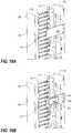
- FIG. 1is a front isometric view of an electronic equipment enclosure frame in accordance with one or more preferred embodiments of the present invention, shown with a pair of vertical mounting rails installed thereon;
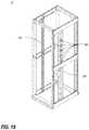
- FIG. 2is an isometric view of a frame structure of similar construction to that of FIG. 1 , but of greater depth, shown with panels installed thereon;
- FIG. 3is an isometric view of one of the vertical mounting rails of FIG. 1 .
- FIG. 4is a top cross-sectional view of a portion of the frame structure of FIG. 1 , taken along line 4 - 4 , showing the connection of one of the mounting rails to one of the side cross members;
- FIG. 5is an isometric view of the frame structure of FIG. 1 , shown with a plurality of D-rings mounted on each vertical mounting rail;
- FIG. 6is an enlarged fragmentary isometric view of the top right corner of the frame structure of FIG. 5 ;
- FIG. 7is an enlarged fragmentary orthogonal view of one of the D-rings of FIG. 5 shown detached from the vertical mounting rail;
- FIG. 8is an isometric view of a frame structure of similar construction to that of FIG. 1 , but of greater depth and width, shown with an alternative type of vertical mounting rail installed thereon;
- FIG. 9is an isometric view of one of the vertical mounting rails of FIG. 8 ;
- FIG. 10is an enlarged fragmentary isometric view of the top left corner of the frame structure of FIG. 8 ;
- FIGS. 11 and 12are enlarged fragmentary orthogonal views of the left side and rear of one of the D-rings of FIG. 8 shown detached from the vertical mounting rail;
- FIG. 13is a fragmentary isometric view of a top portion of the vertical mounting rail of FIG. 3 , shown with a plurality of cable management structures in the form of multi-fingered cable guides mounted thereon;
- FIG. 14is an exploded fragmentary isometric view of the vertical mounting rail and cable guides of FIG. 13 ;
- FIG. 15is a fragmentary isometric view of a top portion of the vertical mounting rail of FIG. 9 , taken from the left side, shown with a plurality of cable management structures in the form of multi-fingered cable guides, doors and door supports mounted thereon;
- FIG. 16Ais a partially exploded fragmentary isometric view, taken from the right side, of the arrangement of FIG. 15 ;
- FIG. 16Bis a partially exploded fragmentary isometric view, taken from the right side, of an alternative embodiment of the arrangement of FIG. 16A ;
- FIG. 17is an isometric view of the frame structure of FIG. 1 , shown with a T-channel cable manager array mounted on one of the vertical mounting rails;
- FIG. 18is an isometric view of the frame structure of FIG. 1 , shown with a plurality of cable manager spools mounted on one of the vertical mounting rails;
- FIG. 19is an isometric view of the frame structure of FIG. 1 , shown with a plurality of vertical C-channel cable managers mounted on one of the vertical mounting rails;
- FIG. 20is an isometric view of the frame structure of FIG. 1 , shown with a multi-finger cable manager array mounted on one of the vertical mounting rails.
- any sequence(s) and/or temporal order of steps of various processes or methods that are described hereinare illustrative and not restrictive. Accordingly, it should be understood that, although steps of various processes or methods may be shown and described as being in a sequence or temporal order, the steps of any such processes or methods are not limited to being carried out in any particular sequence or order, absent an indication otherwise. Indeed, the steps in such processes or methods generally may be carried out in various different sequences and orders while still falling within the scope of the present invention. Accordingly, it is intended that the scope of patent protection afforded the present invention is to be defined by the appended claims rather than the description set forth herein.
- a picnic basket having an appledescribes “a picnic basket having at least one apple” as well as “a picnic basket having apples.”
- a picnic basket having a single appledescribes “a picnic basket having only one apple.”
- a picnic basket having cheese or crackersdescribes “a picnic basket having cheese without crackers,” “a picnic basket having crackers without cheese,” and “a picnic basket having both cheese and crackers.”
- “and”denotes “all of the items of the list.”
- reference to “a picnic basket having cheese and crackers”describes “a picnic basket having cheese, wherein the picnic basket further has crackers,” as well as describes “a picnic basket having crackers, wherein the picnic basket further has cheese.”
- FIG. 1is a front isometric view of an electronic equipment enclosure frame 12 in accordance with one or more preferred embodiments of the present invention, shown with a pair of vertical mounting rails 230 installed thereon.
- the frame structure 12includes four vertical support posts 16 , upper and lower front cross members 17 , 18 , upper and lower rear cross members 19 , 20 and three pairs of side cross members 21 , 22 , 23 .
- Each vertical support post 16includes a plurality of cross member attachment apertures at each end. Two of the vertical support posts 16 are connected together at their upper and lower ends by the upper and lower front cross members 17 , 18 , respectively, and the other two support posts 16 are connected together at their upper and lower ends by the upper and lower rear cross members 19 , 20 , respectively.
- the front cross members 17 , 18 and their respective support posts 16thus define a front frame (sometimes referred to as a door threshold frame) 24
- the rear cross members 19 , 20 and their respective support posts 16define a rear door threshold frame 26
- the front and rear frames 24 , 26may then be connected together at their respective corners by the upper, middle and lower side cross members 21 , 22 , 23 .
- each upper and lower cross member 17 , 19 and 18 , 20includes a plurality of tabs or gussets, adapted to interact with a respective end of a vertical support post 16 , extending therefrom, and these tabs may be plug welded to the vertical support posts 16 .
- Such an arrangementmay be disclosed, for example, in co-pending, commonly-assigned non-provisional patent application Ser. No. 13/229,704, entitled, “ELECTRONIC EQUIPMENT CABINET STRUCTURE” (the “'704 Application”).
- the lower corners of each frame 24 , 26may be reinforced and supported by caster plates which in turn are supported by casters.
- Such an arrangementmay also be disclosed, for example, in the '704 Application.
- FIG. 2is an isometric view of a frame structure 12 of similar construction to that of FIG. 1 , but of greater depth, shown with panels installed thereon.
- the enclosure 10may include right and/or left panels 13 , a front panel 14 , and a rear panel 15 , one or more of which may be configured to operate as a door to the interior of the enclosure 10 (not illustrated).
- Various different connection meansmay be used to join the various panels 13 , 14 , 15 to the frame structure 12 .
- One or more novel connection meansmay be described and/or illustrated herein. However, although not illustrated herein, it will be apparent to the Ordinary Artisan that in at least some embodiments, any of a variety of other connection means may be used instead to join the panels to the frame structure 12 .
- the enclosure 10further includes a generally flat top panel 30 sized and shaped to fit an opening 28 defined by the four vertical support posts 16 in connection with the upper front cross member 17 , the upper rear cross member 19 , and the upper side cross members 21 . When installed, the top panel 30 covers the opening 28 .
- the top panel 30is manufactured from sheet metal or other metal-based material.
- the top panel 30may include features such as those described in co-pending, commonly-assigned non-provisional patent application Ser. No. 13/229,705, entitled, “CABLE PASS-THROUGH PANEL FOR ELECTRONIC EQUIPMENT ENCLOSURE” (the “'705 Application”).
- the upper front and rear cross members 17 , 19each include two spring pins 56 and a retaining flange 51 as seen, for example, in FIG. 1 .
- the spring pins 56 and end flanges 51may be utilized to facilitate reversible, tool-free installation of the top panel 30 .
- the frame structure 12further includes one or more vertical mounting rails 230 that extend therein in a generally vertical orientation.
- Each vertical mounting rail 230typically has a series of holes 232 formed therein to facilitate easy mounting of a wide variety of equipment to the frame structure 12 .
- one or more mounting clamps 240may be used to facilitate attachment of the vertical mounting rail 230 to the frame structure 12 .
- Other examples of frame structures with vertical mounting railsare described in commonly-assigned U.S. Pat. Nos. 5,997,117, 7,839,635, 7,804,685, U.S. Patent Application Publication No. US 2009/0227197 A1, and U.S. Patent Application Publication No.
- vertical mounting railsmay be supported by the side cross members of the frame, by separate side horizontal rails that are not part of the primary frame structure, or by other means entirely.
- FIG. 3is an isometric view of one of the vertical mounting rails 230 of FIG. 1
- FIG. 4is a top cross-sectional view of a portion of the frame structure 12 of FIG. 1 , taken along line 4 - 4 , showing the connection of one of the mounting rails 230 to one of the side cross members 21 .
- the mounting rail 230 in FIG. 3is shown in the same orientation as that of the rightmost mounting rail 230 of FIG. 1 .
- the vertical mounting rail 230is an elongate structure whose cross-section generally includes a C-shaped portion 234 , a first support portion 233 extending from one end of the C-shaped portion 234 , a second support portion 235 extending perpendicularly from the first support portion 233 , and a third support portion 237 extending perpendicularly from the second support portion 235 .
- Each vertical mounting rail 230may be fastened to the cabinet structure 12 using one or more clamps 240 .
- the mounting clamp 240includes a clamping bracket 242 and a clamp nut 244
- the rail 230includes a plurality of embossed portions 254 for interfacing with the clamp 240 .
- Extending at opposite lateral edges of the clamping bracket 242are flanges 246 , 247 .
- the flanges 246 , 247 of the clamping bracket 242straddle the C-shaped portion 234 of the vertical mounting rail 230 , and the clamp nut 244 may be aligned with the embossed portion 254 of the vertical mounting rail 230 , which itself is aligned with a raised central portion of the clamping bracket 242 .
- FIG. 5is an isometric view of the frame structure 12 of FIG. 1 , shown with a plurality of D-rings 260 mounted on each vertical mounting rail 230
- FIG. 6is an enlarged fragmentary isometric view of the top right corner of the frame structure 12 of FIG. 5 .
- the first support portion 233includes two types of openings 252 , 253 , arranged in sets. In each set are two keyhole apertures 252 disposed above a single horizontal slot 253 .
- the second support portion 235also includes two types of openings 255 , 257 ; circular openings 255 are arranged in a column and evenly-spaced along the length of the rail 230 , and vertical slots 257 are arranged in pairs that are likewise evenly-spaced, though at greater spacings, along the rail 230 .
- the third support portion 237includes the equipment mounting holes 232 mentioned previously. These holes are preferably square, but may alternatively be round, and are arranged in a conventional, standardized repeating pattern having intervals (on center) of 5 ⁇ 8′′-5 ⁇ 8′′-1 ⁇ 2′′ totaling a standard rack mounting unit (“RMU”) of 1.75′′.
- the third support portion 237thus serves as an equipment mounting rail, suitable for use in like manner to conventional equipment mounting rails having conventionally-spaced mounting apertures like those shown and described herein.
- FIG. 7is an enlarged fragmentary orthogonal view of one of the D-rings 260 of FIG. 5 shown detached from the vertical mounting rail 230 .
- Each D-ring 260includes a ring portion 261 and a support portion.
- the ring portion 261may be generally similar in construction to, for example, cable rings described and illustrated in commonly-assigned U.S. Pat. No.
- the support portionincludes three elements: a first keyhole boss 262 extending laterally from the back of a tab 264 protruding upward from the back of the ring portion 261 , a second keyhole boss (not visible, but similar to the first keyhole boss 262 ) extending laterally from the back of the ring portion 261 , and an alignment boss 266 protruding from the end of a tab 268 extending downward from the back of the ring portion 261 .
- the support portion of the D-ring 260is adapted to be connected to, and supported by, one set of openings 252 , 253 in the vertical mounting rail 230 without interfering with the use of the equipment mounting holes 232 .
- the two keyhole bosses 262are arranged to interact with the keyhole apertures 252 , of the selected set of openings 252 , 253 , in the first support portion 233 , and the alignment boss 266 is arranged to interact with the horizontal slot 253 of the same set of openings 252 , 253 . This interaction may perhaps be best discerned from FIGS. 6 and 7 .
- FIG. 8is an isometric view of a frame structure 12 of similar construction to that of FIG. 1 , but of greater depth and width, shown with an alternative type of vertical mounting rail 330 installed thereon
- FIG. 9is an isometric view of one of the vertical mounting rails 330 of FIG. 8 .
- the mounting rail 330 in FIG. 9is shown in the same orientation as that of the rightmost mounting rail 330 of FIG. 1 .
- FIG. 10is an enlarged fragmentary isometric view of the top left corner of the frame structure 12 of FIG. 8 .
- the alternative mounting rail 330 of FIGS. 8-10shares many similarities with the mounting rail 230 of FIGS. 1 and 3 .
- the alternative vertical mounting rail 330is an elongate structure whose cross-section generally includes a C-shaped portion 234 , a first support portion 333 extending from one end of the C-shaped portion, a second support portion 335 extending perpendicularly from the first support portion 333 , and a third support portion 237 extending perpendicularly from the second support portion 335 .
- the rail 330may be fastened to the cabinet structure 12 using one or more clamps 240 in similar fashion to that of FIG. 3 .
- the first support portion 333includes at least two types of openings 252 , 253 , arranged in sets. In each set are two pairs of keyhole apertures 252 disposed above a single horizontal slot 253 , which is centered therebetween.
- the second support portion 335includes circular openings 255 are arranged in a column and evenly-spaced along the length of the rail 330 .
- the third support portion 237includes the standardized equipment mounting holes 232 mentioned previously.
- one or more of the support portions 333 , 335 , 237may be adapted to facilitate routing of cables from one side of the frame structure 12 to the other.
- Options and features for accommodating cable pass-through at a vertical mounting railmay be disclosed, for example, in co-pending, commonly-assigned non-provisional patent application Ser. No. 13/229,706, entitled, “RAIL SEAL FOR ELECTRONIC EQUIPMENT ENCLOSURE” (the “'706 Application”).
- FIGS. 8 and 10the cable management structures that are mounted on the vertical mounting rails are D-rings 360 , although a wide variety of different cable management structures may be mounted to the vertical mounting rails, as will be explained in further detail below.
- FIGS. 11 and 12are enlarged fragmentary orthogonal view of the left side and rear of one of the D-rings 360 of FIG. 8 shown detached from the vertical mounting rail 330 .
- Each D-ring 360includes a ring portion 361 and a support portion.
- the ring portion 361may be generally similar in construction to the ring portion of the D-rings of FIGS. 5-7 and variations thereof.
- the support portionincludes five elements: four keyhole bosses 362 extending laterally from the back of the ring portion 361 , and an alignment boss 266 protruding from the end of a tab 368 extending downward from a central area of the back of the ring portion 361 .
- the support portion of the D-ring 360is adapted to be connected to, and supported by, one set of openings 252 , 253 in the vertical mounting rail 330 without interfering with the use of the equipment mounting holes 232 .
- the four keyhole bosses 362are arranged to interact with the keyhole apertures 252 , of the selected set of openings 252 , 253 , in the first support portion 333 , and the alignment boss 266 is arranged to interact with the horizontal slot 253 of the same set of openings 252 , 253 .
- This interactionmay perhaps be best discerned from FIGS. 10-12 but is somewhat similar to that of the D-rings 260 shown in FIGS. 6 and 7 .
- the D-rings 260 , 360 described and illustrated hereinmay be connected to, or mounted on, the vertical mounting rails 230 , 330 without the use of tools.
- the D-rings 260 , 360may be mounted by inserting the keyhole bosses 262 , 362 into the upper (wider) portion of respective keyhole apertures 252 and lowering them until they are seated in the lower (narrower) portion thereof, at which point the alignment boss 266 snaps into place in the horizontal slot 253 .
- keyhole apertures 252may be of varying sizes.
- an upper keyhole aperturemay be smaller than a lower keyhole aperture.
- FIG. 13is a fragmentary isometric view of a top portion of the vertical mounting rail 230 of FIG. 3 , shown with a plurality of cable management structures in the form of multi-fingered cable guides 270 mounted thereon, and FIG. 14 is an exploded fragmentary isometric view of the vertical mounting rail 230 and cable guides 270 of FIG. 13 .
- each cable guideincludes a cable ring portion 272 , which includes a plurality of T-shaped fingers 276 forming cable rings therebetween, and a base portion 274 , which is generally planar and includes a plurality of circular openings 278 arranged in a column and distributed along the length thereof at a spacing that corresponds to that of the openings 255 in the second support portion 235 of the mounting rail 230 .
- cable management structures suitable for use as the cable ring portions 272 of the present inventionare shown and described in commonly-assigned U.S. Pat. No. 7,119,282, entitled “VERTICAL CABLE MANAGEMENT RACK,” the entirety of which is incorporated herein by reference.
- the T-shaped fingers 276are preferably arranged at 1 RMU spacings.
- the multi-fingered cable guides 270may be attached to, and flush against, the second support portion 235 of the mounting rail 230 using fasteners 280 .
- unrestricted access to the sets of openings 252 , 253 in the first support portion 233continues to be available, thereby permitting D-rings 260 or other cable management structures to be mounted thereto if desired.
- the cable rings formed by the T-shaped fingers 276are conveniently located alongside equipment mounted to the equipment mounting rails (third support portions) 233 . Still further, because the T-shaped fingers 276 and the cable rings formed thereby are arranged at 1 RMU spacings, the cable rings are aligned with conventional, standardized rack mounting locations defined by the equipment mounting holes 232 .
- FIG. 15is a fragmentary isometric view of a top portion of the vertical mounting rail 330 of FIG. 9 , taken from the left side, shown with a plurality of cable management structures in the form of multi-fingered cable guides 270 , doors 282 and door supports 284 mounted thereon
- FIG. 16Ais a partially exploded fragmentary isometric view, taken from the right side, of the arrangement of FIG. 15 .
- the cable guides 270are similar to those of FIGS. 13 and 14 and are installed in like manner to the second support portions 335 of a mounting rail 330 .
- the doors 282may be supported along one side with hinges 286 supported between adjacent ends of the T-shaped fingers 276 and on the other side by the door supports 284 . As shown in FIG.
- FIG. 16Ais a partially exploded fragmentary isometric view, taken from the right side, of an alternative embodiment of the arrangement of FIG. 16A .
- a door support 384may itself include an aperture 385 to permit cables to pass therethrough. Edges 387 of the aperture 385 can be rounded so as to prevent unnecessary friction against cables positioned to pass through the aperture 385 . Further details regarding the arrangement of FIGS. 15, 16A and 16B can be found in the '706 Application.
- cable management structuresmay be separately anchored to the vertical mounting rail 230 , 330 or frame structure 12 after being fastened to the vertical mounting rail 230 , 330 . Such anchoring may be facilitated with a separate fastener. In at least some other embodiments, such anchoring is not required for structural stability.
- FIGS. 17-20illustrate the frame structure 12 of FIG. 1 with various other cable management structures mounted to the vertical mounting rails 230 .
- FIG. 17is an isometric view of the frame structure 12 of FIG. 1 , shown with a T-channel cable manager array 401 mounted on one of the vertical mounting rails 230 .
- FIG. 18is an isometric view of the frame structure 12 of FIG. 1 , shown with a plurality of cable manager spools 402 mounted on one of the vertical mounting rails 230 .
- FIG. 19is an isometric view of the frame structure 12 of FIG. 1 , shown with a plurality of vertical C-channel cable managers 403 mounted on one of the vertical mounting rails 230 .
- FIG. 20is an isometric view of the frame structure 12 of FIG. 1 , shown with a multi-finger cable manager array 404 mounted on one of the vertical mounting rails 230 .
Landscapes
- Engineering & Computer Science (AREA)
- Microelectronics & Electronic Packaging (AREA)
- Physics & Mathematics (AREA)
- Thermal Sciences (AREA)
- Casings For Electric Apparatus (AREA)
- Insertion, Bundling And Securing Of Wires For Electric Apparatuses (AREA)
Abstract
Description
- (a) U.S. provisional patent application Ser. No. 61/381,905, filed Sep. 10, 2010, and entitled, “CABLE PASS-THROUGH PANEL FOR ELECTRONIC EQUIPMENT ENCLOSURE;”
- (b) U.S. provisional patent application Ser. No. 61/381,909, filed Sep. 10, 2010, and entitled, “RAIL SEAL FOR ELECTRONIC EQUIPMENT ENCLOSURE;”
- (c) U.S. provisional patent application Ser. No. 61/381,912, filed Sep. 10, 2010, and entitled, “RAIL MOUNTING CLAMP FOR ELECTRONIC EQUIPMENT ENCLOSURE;”
- (d) U.S. provisional patent application Ser. No. 61/381,918, filed Sep. 10, 2010, and entitled, “VERTICAL MOUNTING RAIL WITH CABLE MANAGEMENT FEATURES;”
- (e) U.S. non-provisional patent application Ser. No. 13/229,705, filed Sep. 10, 2011, published on Mar. 15, 2012 as U.S. Patent Application Publication No. US 2012/0062086 A1, and entitled, “CABLE PASS-THROUGH PANEL FOR ELECTRONIC EQUIPMENT ENCLOSURE;”
- (f) U.S. non-provisional patent application Ser. No. 13/229,706, filed Sep. 10, 2011, published on Mar. 15, 2012 as U.S. Patent Application Publication No. US 2012/0063099 A1, and entitled, “RAIL SEAL FOR ELECTRONIC EQUIPMENT ENCLOSURE;”
- (g) U.S. non-provisional patent application Ser. No. 13/229,707, filed Sep. 10, 2011, published on Mar. 15, 2012 as U.S. Patent Application Publication No. US 2012/0062083 A1, entitled, “RAIL MOUNTING CLAMP FOR ELECTRONIC EQUIPMENT ENCLOSURE,” and issued on Jul. 22, 2014 as U.S. Pat. No. 8,787,023; and
- (h) U.S. non-provisional patent application Ser. No. 13/229,708, filed Sep. 10, 2011, published on Mar. 15, 2012 as U.S. Patent Application Publication No. US 2012/0062091 A1, and entitled, “VERTICAL MOUNTING RAIL WITH CABLE MANAGEMENT FEATURES.”
Claims (24)
Priority Applications (2)
| Application Number | Priority Date | Filing Date | Title |
|---|---|---|---|
| US16/801,936US11039543B2 (en) | 2010-09-10 | 2020-02-26 | Vertical mounting rail with cable management features |
| US17/345,384US20210307183A1 (en) | 2010-09-10 | 2021-06-11 | Vertical mounting rail with cable management features |
Applications Claiming Priority (11)
| Application Number | Priority Date | Filing Date | Title |
|---|---|---|---|
| US38190410P | 2010-09-10 | 2010-09-10 | |
| US38190510P | 2010-09-10 | 2010-09-10 | |
| US13/229,705US20120062086A1 (en) | 2010-09-10 | 2011-09-10 | Cable pass-through panel for electronic equipment enclosure |
| US13/229,704US8901438B2 (en) | 2010-09-10 | 2011-09-10 | Electronic equipment cabinet structure |
| US14/157,349US9055677B2 (en) | 2010-09-10 | 2014-01-16 | Cable pass-through panel for electronic equipment enclosure |
| US14/541,507US9408326B2 (en) | 2010-09-10 | 2014-11-14 | Electronic equipment cabinet structure |
| US14/711,211US9781852B2 (en) | 2010-09-10 | 2015-05-13 | Cable pass-through panel for electronic equipment enclosure |
| US15/062,372US9642270B2 (en) | 2010-09-10 | 2016-03-07 | Rail seal for electronic equipment enclosure |
| US15/581,982US10237994B2 (en) | 2010-09-10 | 2017-04-28 | Vertical mounting rail with cable management features |
| US16/356,151US10588227B2 (en) | 2010-09-10 | 2019-03-18 | Vertical mounting rail with cable management features |
| US16/801,936US11039543B2 (en) | 2010-09-10 | 2020-02-26 | Vertical mounting rail with cable management features |
Related Parent Applications (1)
| Application Number | Title | Priority Date | Filing Date |
|---|---|---|---|
| US16/356,151ContinuationUS10588227B2 (en) | 2010-09-10 | 2019-03-18 | Vertical mounting rail with cable management features |
Related Child Applications (1)
| Application Number | Title | Priority Date | Filing Date |
|---|---|---|---|
| US17/345,384ContinuationUS20210307183A1 (en) | 2010-09-10 | 2021-06-11 | Vertical mounting rail with cable management features |
Publications (2)
| Publication Number | Publication Date |
|---|---|
| US20200196465A1 US20200196465A1 (en) | 2020-06-18 |
| US11039543B2true US11039543B2 (en) | 2021-06-15 |
Family
ID=45805977
Family Applications (10)
| Application Number | Title | Priority Date | Filing Date |
|---|---|---|---|
| US13/229,704Expired - Fee RelatedUS8901438B2 (en) | 2010-09-10 | 2011-09-10 | Electronic equipment cabinet structure |
| US14/541,507Expired - Fee RelatedUS9408326B2 (en) | 2010-09-10 | 2014-11-14 | Electronic equipment cabinet structure |
| US15/062,372ActiveUS9642270B2 (en) | 2010-09-10 | 2016-03-07 | Rail seal for electronic equipment enclosure |
| US15/492,741ActiveUS9814159B2 (en) | 2010-09-10 | 2017-04-20 | Rail seal for electronic equipment enclosure |
| US15/581,982ActiveUS10237994B2 (en) | 2010-09-10 | 2017-04-28 | Vertical mounting rail with cable management features |
| US15/582,708ActiveUS9980400B2 (en) | 2010-09-10 | 2017-04-30 | Rail seal for electronic equipment enclosure |
| US15/983,832ActiveUS10178784B2 (en) | 2010-09-10 | 2018-05-18 | Rail seal for electronic equipment enclosure |
| US16/356,151ActiveUS10588227B2 (en) | 2010-09-10 | 2019-03-18 | Vertical mounting rail with cable management features |
| US16/801,936ActiveUS11039543B2 (en) | 2010-09-10 | 2020-02-26 | Vertical mounting rail with cable management features |
| US17/345,384AbandonedUS20210307183A1 (en) | 2010-09-10 | 2021-06-11 | Vertical mounting rail with cable management features |
Family Applications Before (8)
| Application Number | Title | Priority Date | Filing Date |
|---|---|---|---|
| US13/229,704Expired - Fee RelatedUS8901438B2 (en) | 2010-09-10 | 2011-09-10 | Electronic equipment cabinet structure |
| US14/541,507Expired - Fee RelatedUS9408326B2 (en) | 2010-09-10 | 2014-11-14 | Electronic equipment cabinet structure |
| US15/062,372ActiveUS9642270B2 (en) | 2010-09-10 | 2016-03-07 | Rail seal for electronic equipment enclosure |
| US15/492,741ActiveUS9814159B2 (en) | 2010-09-10 | 2017-04-20 | Rail seal for electronic equipment enclosure |
| US15/581,982ActiveUS10237994B2 (en) | 2010-09-10 | 2017-04-28 | Vertical mounting rail with cable management features |
| US15/582,708ActiveUS9980400B2 (en) | 2010-09-10 | 2017-04-30 | Rail seal for electronic equipment enclosure |
| US15/983,832ActiveUS10178784B2 (en) | 2010-09-10 | 2018-05-18 | Rail seal for electronic equipment enclosure |
| US16/356,151ActiveUS10588227B2 (en) | 2010-09-10 | 2019-03-18 | Vertical mounting rail with cable management features |
Family Applications After (1)
| Application Number | Title | Priority Date | Filing Date |
|---|---|---|---|
| US17/345,384AbandonedUS20210307183A1 (en) | 2010-09-10 | 2021-06-11 | Vertical mounting rail with cable management features |
Country Status (1)
| Country | Link |
|---|---|
| US (10) | US8901438B2 (en) |
Cited By (9)
| Publication number | Priority date | Publication date | Assignee | Title |
|---|---|---|---|---|
| US11133656B2 (en) | 2010-01-17 | 2021-09-28 | Chatsworth Products, Inc. | Vertical cable manager |
| US11464123B2 (en) | 2010-09-10 | 2022-10-04 | Chatsworth Products, Inc. | Method of adapting an electronic equipment enclosure for cable management |
| US11622458B1 (en) | 2020-12-15 | 2023-04-04 | Chatsworth Products, Inc. | Brush port assembly and method for installing same |
| US11647610B2 (en) | 2013-01-11 | 2023-05-09 | Chatsworth Products, Inc. | Modular thermal isolation barrier for data processing equipment structure |
| US11678456B1 (en) | 2020-12-15 | 2023-06-13 | Chatsworth Products, Inc. | Slidable mounting hardware for electronic equipment enclosure and method for installing same |
| US11818861B1 (en) | 2020-12-15 | 2023-11-14 | Chatsworth Products, Inc. | Frame structure for electronic equipment enclosure |
| US11920392B1 (en) | 2021-02-02 | 2024-03-05 | Chatsworth Products, Inc. | Electrical bonding door hinges |
| US11985799B2 (en) | 2013-12-17 | 2024-05-14 | Chatsworth Products, Inc. | Electronic equipment enclosure |
| US12048108B1 (en) | 2020-12-15 | 2024-07-23 | Chatsworth Products, Inc. | Caster attachment system using mating features |
Families Citing this family (49)
| Publication number | Priority date | Publication date | Assignee | Title |
|---|---|---|---|---|
| US7804685B2 (en) | 2005-09-19 | 2010-09-28 | Chatsworth Products, Inc. | Ducted exhaust equipment enclosure |
| US20090283488A1 (en) | 2008-05-19 | 2009-11-19 | Chatsworth Products, Inc. | Seismically hardened two-post electronic equipment rack |
| US8901438B2 (en) | 2010-09-10 | 2014-12-02 | Chatsworth Products, Inc. | Electronic equipment cabinet structure |
| US8787023B2 (en) | 2010-09-10 | 2014-07-22 | Chatsworth Products, Inc. | Rail mounting clamp for electronic equipment enclosure |
| US9560777B2 (en) | 2010-11-08 | 2017-01-31 | Chatsworth Products, Inc. | Door closer mechanism for hot/cold aisle air containment room |
| US9185824B2 (en)* | 2011-04-26 | 2015-11-10 | Panduit Corp. | Cable pathway system for network architecture |
| US20120292267A1 (en)* | 2011-05-17 | 2012-11-22 | Mellanox Technologies Ltd. | Mounting rail with internal power cable |
| US11246231B2 (en) | 2012-02-10 | 2022-02-08 | Chatsworth Products, Inc. | Door closer mechanism for hot/cold aisle air containment room |
| US8925739B2 (en)* | 2012-07-26 | 2015-01-06 | Lenovo Enterprise Solutions (Singapore) Pte. Ltd. | High-capacity computer rack with rear-accessible side bays |
| FR2999819B1 (en)* | 2012-12-19 | 2015-01-16 | Airbus Operations Sas | ELECTRONIC STRUCTURE COMPRISING AT LEAST ONE PARTICLE-SEALED BARRIER |
| US20140317902A1 (en)* | 2013-04-30 | 2014-10-30 | Calvary Applied Technologies, LLC | Rack door transition kit with universal bracket |
| US20150027350A1 (en)* | 2013-07-24 | 2015-01-29 | Nick T. Castillo | Outdoor kitchen unit |
| KR102086382B1 (en)* | 2013-08-23 | 2020-04-14 | 삼성전자주식회사 | Air Conditioner |
| US9282660B2 (en)* | 2013-09-17 | 2016-03-08 | Dell Products, Lp | Modular data center cabinet rack |
| DE102014101402B4 (en)* | 2014-02-05 | 2024-10-17 | Rittal Gmbh & Co. Kg | Frame profile for a frame of a control cabinet |
| CN106104022B (en)* | 2014-03-12 | 2018-03-23 | 利塔尔两合公司 | For installing the fixed system of equipment, particularly household electrical appliance |
| US10178911B2 (en) | 2015-06-04 | 2019-01-15 | International Business Machines Corporation | Safety apparatus for electrical equipment rack |
| US9456520B1 (en)* | 2015-09-25 | 2016-09-27 | Innovation First, Inc. | Server rack system for mounting equipment |
| US9814156B2 (en) | 2015-09-25 | 2017-11-07 | Innovation First, Inc. | Server rack system for mounting equipment |
| CA2950839C (en) | 2016-01-30 | 2023-09-12 | Cooper Technologies Company | Equipment rack and components thereof |
| US11502488B2 (en)* | 2016-04-08 | 2022-11-15 | Commscope Inc. Of North Carolina | Cable management assembly for variable length cables |
| WO2018022721A1 (en) | 2016-07-26 | 2018-02-01 | Chatsworth Products, Inc. | Features for cable managers and other electronic equipment structures |
| CA2985755A1 (en) | 2016-11-17 | 2018-05-17 | Cooper Technologies Company | Electrical panel enclosure including baffle to inhibit water ingress |
| USD857639S1 (en) | 2016-11-17 | 2019-08-27 | Cooper Technologies Company | Single door for electrical panel enclosure |
| CA2985754C (en) | 2016-11-17 | 2024-06-11 | Cooper Technologies Company | One or more doors with one or more angled side flanges for electrical panel enclosure |
| US9955607B1 (en)* | 2016-12-21 | 2018-04-24 | Mountain Stone Technologies, LLC | Electronic equipment vertical mount and stack rack |
| US10172255B2 (en) | 2017-01-26 | 2019-01-01 | International Business Machines Corporation | Enhanced rack/cabinet mobility and stability for a server rack |
| US20190021178A1 (en)* | 2017-07-14 | 2019-01-17 | Panduit Corp. | Faux Column Intermediate Distribution Frame Enclosure |
| TWI645812B (en)* | 2017-10-31 | 2019-01-01 | 川湖科技股份有限公司 | Slide rail mechanism |
| US10506729B2 (en)* | 2017-11-10 | 2019-12-10 | Commscope Technologies Llc | Electronics enclosure with low-profile door |
| US10448536B2 (en)* | 2017-12-14 | 2019-10-15 | Aviat U.S., Inc. | Portable rack dolly, retrofit kit and methods of use |
| US10674627B2 (en)* | 2018-02-08 | 2020-06-02 | Quanta Computer Inc. | Modifiable rack post |
| FR3082824A1 (en) | 2018-06-20 | 2019-12-27 | Airbus Operations | TRANSVERSE CHASSIS FOR AN AVIONIC HOLDER OF AN AIRCRAFT, ASSEMBLY MODULE AND AIRCRAFT COMPRISING SAID TRANSVERSE CHASSIS |
| FR3082913B1 (en)* | 2018-06-20 | 2022-01-21 | Airbus Operations Sas | COUPLING FOR CONNECTING TWO PORTIONS OF AN AIR CIRCUIT, JUNCTION DEVICE COMPRISING SAID COUPLING AND AIR CIRCUIT OF AN AIRCRAFT COMPRISING SAID JUNCTION DEVICE |
| NL2023678B1 (en)* | 2019-08-21 | 2021-04-13 | Legrand France | Fastening element for attachment of a mounting rail of a housing for accommodating electrical, electronic and/or optical equipment, assembly of said mounting rail and said fastening element, and a housing comprising said assembly |
| NL2023676B1 (en) | 2019-08-21 | 2021-04-13 | Legrand France | Assembly of a thin sheet metal part and a substrate part to which the thin sheet metal part is connected |
| US11346466B2 (en) | 2019-10-07 | 2022-05-31 | Schrott GmbH | Cable management systems |
| US20210219446A1 (en)* | 2020-01-15 | 2021-07-15 | Dell Products L.P. | Vibration damping and shock isolation in transportation tote |
| US11582874B2 (en) | 2020-01-15 | 2023-02-14 | Dell Products L.P. | Interlocking transportation totes |
| US11622469B2 (en)* | 2020-05-04 | 2023-04-04 | Panduit Corp. | Data center cabinet and reusable transport casters for a data center cabinet |
| US11678451B2 (en) | 2020-05-04 | 2023-06-13 | Panduit Corp. | Data center cabinet |
| US12035501B2 (en) | 2020-05-04 | 2024-07-09 | Panduit Corp. | Data center cabinet |
| US11432429B2 (en) | 2020-05-05 | 2022-08-30 | Hoffman Enclosures Inc. | Adjustable barrier for enclosures |
| USD1001621S1 (en) | 2020-06-02 | 2023-10-17 | Panduit Corp. | Cable management fingers |
| CN113286480B (en)* | 2021-05-24 | 2022-09-20 | 北京广利核系统工程有限公司 | Fixing device and electrical equipment of machine case |
| US11968798B2 (en)* | 2021-06-30 | 2024-04-23 | Panduit Corp. | Transport caster assembly for a data center cabinet |
| US11723159B2 (en) | 2021-07-26 | 2023-08-08 | Fang-Shou LEE | Thermally insulated, rigid cabinet |
| US20240106487A1 (en)* | 2022-09-24 | 2024-03-28 | Ubicquia, Inc. | Cable bracket and guide system for an electronic device |
| WO2024075215A1 (en)* | 2022-10-05 | 2024-04-11 | 日産自動車株式会社 | Stationary fuel cell system and power generation plant |
Citations (310)
| Publication number | Priority date | Publication date | Assignee | Title |
|---|---|---|---|---|
| US824544A (en) | 1905-12-04 | 1906-06-26 | George Hossege | Pipe-hanger. |
| US1129040A (en) | 1914-01-27 | 1915-02-16 | Franklin P Smith | Joint for structural metal-work. |
| US1919166A (en) | 1931-01-09 | 1933-07-18 | Railroad Accessories Corp | Relay rack |
| US2039886A (en) | 1936-05-05 | |||
| US2424217A (en) | 1941-03-12 | 1947-07-22 | Lyon Metal Products Inc | Sheet metal storage cabinet |
| US2459953A (en) | 1944-02-03 | 1949-01-25 | Mills Engineering Company | Panel and fastener assembly |
| US2616142A (en) | 1948-09-15 | 1952-11-04 | Tinnerman Products Inc | Separable fastener |
| US2667368A (en) | 1951-09-14 | 1954-01-26 | Stanley R Ferguson | Clamp for nonmetallic sheathed cables |
| US2756369A (en) | 1953-01-19 | 1956-07-24 | Bailey Meter Co | Panel support structures |
| US2880379A (en) | 1955-01-10 | 1959-03-31 | Baird Atomic Inc | Supporting structure for electronic components |
| US2999190A (en) | 1957-03-11 | 1961-09-05 | Gen Electric | Switchboard |
| US3034844A (en) | 1958-01-21 | 1962-05-15 | Amco Eng | Enclosure |
| US3143195A (en) | 1961-09-12 | 1964-08-04 | Jr William A Schroeder | Locking strip for panels |
| US3192306A (en) | 1962-09-26 | 1965-06-29 | Philco Corp | Cooling wall structure for electronic equipment cabinet |
| US3265419A (en) | 1963-12-30 | 1966-08-09 | Honeywell Inc | Cabinet structure |
| US3404931A (en) | 1967-03-20 | 1968-10-08 | Fall | Cabinet structure |
| US3563627A (en) | 1968-12-03 | 1971-02-16 | Digital Equipment Corp | Cabinet construction |
| US3585333A (en) | 1969-06-30 | 1971-06-15 | Nat Tel Tronics Corp | Rapid assembly clip for mounting components on an electronic chassis |
| US3655254A (en) | 1968-11-20 | 1972-04-11 | Sprecher & Schuh Ag | Cabinet, particularly for electrical installations |
| US3675955A (en) | 1970-03-23 | 1972-07-11 | Regis Mfg Co | Cabinet bracket |
| US3895215A (en) | 1973-11-23 | 1975-07-15 | Jerry Dale Gordon | Cabinet for holding food at a controllable temperature |
| US4040694A (en) | 1974-12-12 | 1977-08-09 | La Telemecanique Electrique | Framework for metal cabinet |
| US4101233A (en) | 1977-03-25 | 1978-07-18 | Interlake, Inc. | Panel mounting clip for storage rack |
| DE7836374U1 (en) | 1978-12-08 | 1979-03-15 | Institut Dr. Friedrich Foerster Pruefgeraetebau, 7410 Reutlingen | Housing for an electronic device |
| US4148453A (en) | 1977-12-08 | 1979-04-10 | Brantly Robert T | Projector stacking stand |
| US4495234A (en) | 1981-10-27 | 1985-01-22 | Toyoda Gosei Co., Ltd. | Weather strip for automobiles |
| US4497411A (en)* | 1982-04-19 | 1985-02-05 | Northern Telecom Limited | Distributing frame for telecommunications systems |
| US4524937A (en) | 1983-01-20 | 1985-06-25 | Robroy Industries | Buckle connection for hanging cable |
| US4551577A (en) | 1983-07-25 | 1985-11-05 | Byrne Norman R | Retractable power center |
| US4553674A (en) | 1981-01-30 | 1985-11-19 | Hitachi, Ltd. | Casing construction for electronic equipment |
| US4592602A (en) | 1983-06-28 | 1986-06-03 | Contraves Ag | Modular mounting rack system of vertical-type construction |
| US4643319A (en) | 1983-12-09 | 1987-02-17 | Rittal-Werk Rudolf Loh Gmbh & Co. Kg | Framework for a switchboard cabinet |
| US4715502A (en) | 1986-02-20 | 1987-12-29 | Newton Instrument Company | Telephone equipment rack |
| US4796541A (en) | 1987-07-31 | 1989-01-10 | Halstrick Robert T | Storage rack |
| US4814942A (en) | 1987-08-10 | 1989-03-21 | Westinghouse Electric Corp. | Drawout switchgear cell frame |
| US4825339A (en) | 1988-01-11 | 1989-04-25 | Tektronix, Inc. | Sheet metal knock-out |
| US4869380A (en) | 1986-09-26 | 1989-09-26 | Vormet Quality Fabrication Close/Corporation | Frame work |
| US4941717A (en) | 1989-10-10 | 1990-07-17 | Skyline Displays, Inc. | Knockdown table and cabinet structure |
| US4944082A (en) | 1989-04-27 | 1990-07-31 | Hewlett Packard Co. | Method of providing a sheet metal housing with precisely positioned mounting references |
| US4962443A (en) | 1988-01-14 | 1990-10-09 | Square D Company | Improved residential loadcenter |
| US4964020A (en) | 1989-09-27 | 1990-10-16 | At&T Bell Laboratories | Equipment rack |
| US4988008A (en) | 1989-06-19 | 1991-01-29 | Siemens Aktiengesellschaft | Supporting framework for a control cabinet |
| US5004107A (en) | 1989-05-05 | 1991-04-02 | Hendry Mechanical Works | Earthquake braced racks |
| US5009383A (en) | 1990-04-30 | 1991-04-23 | Daniel J. Chapman | Suspended ceiling electrical bracket |
| US5020866A (en) | 1989-11-13 | 1991-06-04 | Gichner Systems Group, Inc. | Enclosure for housing electronic components |
| US5052565A (en) | 1989-09-09 | 1991-10-01 | Rittal-Werk Rudolf Loh Gmbh & Co. Kg | Device for fastening a C-shaped mounting rail to a wall provided with screw holes |
| US5149026A (en) | 1991-08-28 | 1992-09-22 | Allen Roger D | Wire support apparatus |
| US5165770A (en) | 1991-03-29 | 1992-11-24 | Richard Hahn | Electronic equipment modular cabinet system |
| US5250752A (en) | 1992-11-23 | 1993-10-05 | Gamlet Incorporated | Knockdown EMI/RFI shielded electronic rack enclosure |
| US5263252A (en) | 1990-03-19 | 1993-11-23 | Bemis Manufacturing Company | Method for making a panel with cutouts formed therein |
| US5275296A (en) | 1991-12-12 | 1994-01-04 | Rittal-Werk Rudolf Loh Gmbh & Co. Kg | Rack for a control cabinet |
| EP0577433A2 (en) | 1992-07-03 | 1994-01-05 | Vero Electronics Limited | Racks for electronic equipment |
| US5284254A (en) | 1992-06-24 | 1994-02-08 | B-Line Systems, Inc. | Rack for electrical equipment |
| US5294748A (en) | 1991-08-20 | 1994-03-15 | Schroff Gmbh | Equipment cabinet |
| US5310255A (en) | 1992-05-18 | 1994-05-10 | Ranallo Paul A | Adjustable drawer guide mounting apparatus |
| US5323916A (en) | 1992-12-23 | 1994-06-28 | Newton Instrument Company, Inc. | Unequal flange-type telephone equipment rack adapted for universal application |
| US5333950A (en) | 1991-12-05 | 1994-08-02 | Rittal-Werk Rudolf Loh Gmbh & Co. Kg | Control cabinet with rack and mounting plate |
| US5372262A (en) | 1991-06-28 | 1994-12-13 | Digital Equipment Corporation | Frame assembly for rack-mountable equipment |
| US5380083A (en) | 1991-11-27 | 1995-01-10 | Federal-Hoffman, Inc. | Multifaceted modular enclosure frame with integral sub-panel guide system |
| US5380803A (en) | 1991-09-18 | 1995-01-10 | Phillips Petroleum Company | Polyethylene blends |
| US5460441A (en) | 1994-11-01 | 1995-10-24 | Compaq Computer Corporation | Rack-mounted computer apparatus |
| US5488543A (en) | 1993-10-06 | 1996-01-30 | Schroff Gmbh | Frame stand |
| US5497444A (en) | 1994-01-21 | 1996-03-05 | Adc Telecommunications, Inc. | High-density fiber distribution frame |
| US5498073A (en) | 1993-10-18 | 1996-03-12 | Schneider Electric Sa | Corner junction for cabinet, and electrical cabinet comprising such junctions |
| US5536079A (en) | 1991-05-22 | 1996-07-16 | Asea Brown Boveri Ltd. | Cabinet |
| US5540339A (en) | 1994-06-13 | 1996-07-30 | Homaco, Inc. | Telecommunications wall rack |
| US5542549A (en) | 1994-11-22 | 1996-08-06 | The Siemon Company | Cross connect frame for communication connector blocks and other devices |
| US5566836A (en) | 1995-06-01 | 1996-10-22 | Homaco, Inc. | Telecommunication relay rack |
| US5586012A (en) | 1993-10-04 | 1996-12-17 | Homaco, Inc. | Vertical organizer comprised of two sections joined together by a splice and secured between two relay racks |
| US5640482A (en) | 1995-08-31 | 1997-06-17 | The Whitaker Corporation | Fiber optic cable management rack |
| US5639150A (en) | 1995-09-22 | 1997-06-17 | Amco Engineering Co. | Electronic component enclosure and method |
| DE19615759A1 (en) | 1996-04-20 | 1997-10-23 | Loh Kg Rittal Werk | Switching cubicle with base and frame structure |
| US5695263A (en) | 1993-02-25 | 1997-12-09 | Knurr-Mechanik Fur Die Elektronik Aktiengesellschaft | Cabinet |
| US5713651A (en) | 1996-02-27 | 1998-02-03 | Mcquay International | Modular frame assembly for an equipment cabinet |
| US5728973A (en) | 1996-08-22 | 1998-03-17 | Hubbell Incorporated | Knockout arrangement providing connection pattern choice on electrical junction box and cover plate arrangement for mounting dynamic loads |
| US5758002A (en) | 1996-12-31 | 1998-05-26 | Siecor Corporation | Routing and storage apparatus for optical fibers |
| US5791498A (en) | 1997-01-21 | 1998-08-11 | Dell U.S.A., L.P. | Rack mount mechanism having an angled bar-nut |
| US5798485A (en) | 1996-12-31 | 1998-08-25 | Dsc Telecom L.P. | Cabinet for housing electronic equipment |
| US5806946A (en) | 1994-11-05 | 1998-09-15 | Rittal-Werk Rudolf Loh Gmbh & Co. Kg | Switchgear cabinet with frame |
| US5806811A (en) | 1996-05-22 | 1998-09-15 | The Siemon Company | Wire manager for use with stand-off legs |
| US5819956A (en) | 1997-02-25 | 1998-10-13 | Sigma-Aldrich Company | Rack for electrical equipment |
| US5933563A (en) | 1997-10-14 | 1999-08-03 | The Whitaker Corporation | Cable enclosure with pass through |
| US5938302A (en) | 1995-09-22 | 1999-08-17 | Amco Engineering Co. | Multiple enclosures and method |
| US5954525A (en) | 1998-04-07 | 1999-09-21 | Ditto Sales, Inc. | Extendable temporary electrical receptacle |
| US5961081A (en) | 1997-04-14 | 1999-10-05 | Sigma-Aldrich Co. | Cable support having pivotally and slidable retainer |
| US5975315A (en) | 1996-07-12 | 1999-11-02 | Northern Telecom Limited | Equipment rack |
| US5992808A (en) | 1998-07-28 | 1999-11-30 | Morrow; Christopher James | Assembly for retaining electrical components |
| US5997117A (en) | 1997-06-06 | 1999-12-07 | Chatsworth Products, Inc. | Rack frame cabinet |
| US6008621A (en) | 1998-10-15 | 1999-12-28 | Electronic Classroom Furniture Systems | Portable computer charging system and storage cart |
| US6011221A (en) | 1998-03-02 | 2000-01-04 | 3Com Corp. | Cable management apparatus and method |
| US6019446A (en) | 1997-03-21 | 2000-02-01 | Schneider Electric Sa | Metal frame with a hyperstatic assembly wedge, notably for an electrical cabinet framework |
| US6036290A (en) | 1998-03-13 | 2000-03-14 | Hoffman Enclosures, Inc. | Seismic subframe for electrical enclosure |
| US6039420A (en) | 1994-11-05 | 2000-03-21 | Rittal-Werk Rudolf Loh Gmbh & Co. Kg | Frame for a switchgear cabinet |
| US6044193A (en) | 1998-07-10 | 2000-03-28 | Siecor Operations, Llc | Fiber optic interconnection enclosure having a forced air system |
| US6047838A (en) | 1997-03-14 | 2000-04-11 | Kewaunee Scientific Corp. | Modular support post |
| US6067233A (en) | 1998-02-27 | 2000-05-23 | 3Com Corporation | Mounting brace and cable management apparatus and method |
| US6065612A (en) | 1999-04-23 | 2000-05-23 | Sigma Aldrich Co. | Relay rack with two-way opening door frame |
| US6095345A (en) | 1998-10-22 | 2000-08-01 | Dell Usa L P | Electronics rack alignment structures |
| US6103973A (en) | 1998-12-22 | 2000-08-15 | Square D Company | Knockout pattern for bundled wire and conduit fittings |
| US6105218A (en) | 1998-12-16 | 2000-08-22 | Siemens Medical Systems, Inc. | Snap-type fastening device |
| US6118073A (en) | 1996-03-01 | 2000-09-12 | Hoffman Enclosures, Inc. | Frame assembly for electrical enclosure |
| US6123400A (en) | 1996-11-19 | 2000-09-26 | Rittal-Werk Rudolf Loh Gmbh & Co. Kg | Switching cabinet |
| US6123203A (en) | 1999-07-13 | 2000-09-26 | Dell Usa L.P. | System and method for mounting a computer system component within a housing |
| US6129316A (en) | 1998-07-23 | 2000-10-10 | The Siemon Company | Telecommunications rack cable support bracket |
| US6135583A (en) | 1998-11-20 | 2000-10-24 | Steelcase Development Inc. | Storage unit |
| US6155658A (en) | 1998-08-18 | 2000-12-05 | Rittal-Werk Rudolf Loh Gmbh & Co. Kg | Profiled frame for a switchgear cabinet |
| WO2001001533A1 (en) | 1999-06-28 | 2001-01-04 | Cooper B-Line Limited | Frame structure for an enclosure for electrical equipment |
| US6179398B1 (en) | 1999-01-29 | 2001-01-30 | Michael Alan Martin | Corner piece and cabinet frame |
| US6181549B1 (en) | 1997-06-24 | 2001-01-30 | Dell Products, L.P. | Chassis retaining system for an electronics rack |
| US6185098B1 (en) | 2000-01-31 | 2001-02-06 | Chatsworth Products, Inc. | Co-location server cabinet |
| US6201919B1 (en) | 1998-12-16 | 2001-03-13 | Adc Telecommunications, Inc | Fiber distribution frame |
| USD440210S1 (en) | 1997-08-07 | 2001-04-10 | Ortronics, Inc. | Cable management rack |
| US6220554B1 (en) | 1998-06-30 | 2001-04-24 | Lucent Technologies, Inc. | Wire clip |
| US6223908B1 (en) | 1999-09-15 | 2001-05-01 | Homaco, Inc. | Adjustable communications equipment dual relay rack |
| US6227502B1 (en) | 2000-03-28 | 2001-05-08 | Jay S Derman | Electrical cord and cable gripper |
| US6231142B1 (en)* | 1998-11-20 | 2001-05-15 | Hans Skeppner | Switch cabinet |
| US6238029B1 (en) | 2000-04-11 | 2001-05-29 | Ads, The Power Resource, Inc. | Universal electronics cabinet |
| US6245998B1 (en) | 1999-10-27 | 2001-06-12 | Avaya Technology Corp. | Cable management assembly for equipment racks |
| US6254207B1 (en) | 1998-02-11 | 2001-07-03 | Legrand | Enclosure, in particular cabinet, especially for electrical equipment |
| US20010015598A1 (en) | 1998-06-23 | 2001-08-23 | Sevier Richard W. | Equipment Mounting racks and cabinets |
| US6282854B1 (en) | 1998-06-05 | 2001-09-04 | Trendway Corporation | Frame-based workplace system |
| US6293637B1 (en) | 2000-05-12 | 2001-09-25 | Amco Engineering Co. | Earthquake-resistant electronic equipment frame |
| US6299268B1 (en) | 1999-09-15 | 2001-10-09 | Schneider Electric Industries Sa | Metallic framework equipped with a progressive tightening corner-piece, in particular for an electrical cabinet |
| US6313405B1 (en) | 1999-08-31 | 2001-11-06 | Cooper Technologies Company | Cable tray |
| US6315132B1 (en) | 1999-07-10 | 2001-11-13 | Rittal-Werk Rudolf Loh Gmbh & Co. Kg | Rack for a switchgear cabinet |
| US6321917B1 (en) | 2000-11-14 | 2001-11-27 | Adc Telecommunications, Inc. | Cable management rack for telecommunications equipment |
| US6327150B1 (en) | 2000-02-10 | 2001-12-04 | Maxtor Corporation | Disk drive test rack with universal electrical connector |
| US6340141B1 (en) | 1997-06-10 | 2002-01-22 | Cooper Technologies Company | Cable support systems, methods, and rack therefor |
| US6347714B1 (en) | 1999-12-17 | 2002-02-19 | Hubbell Incorporated | Vertical cable management system |
| US6349837B1 (en) | 1999-11-10 | 2002-02-26 | Marconi Communications, Inc. | Stiffened relay rack |
| US20020046979A1 (en) | 2000-09-27 | 2002-04-25 | Larsen Lars R. | Adjustable equipment rack |
| US6401940B1 (en) | 1998-03-18 | 2002-06-11 | Rittal-Werk Rudolf Loh Gmbh & Co. Kg | Frame for a switch cabinet |
| US20020074149A1 (en) | 2000-12-20 | 2002-06-20 | Lawrence James I. | Flexible intra-cabinet cable ring wire management system |
| US6410844B1 (en) | 1999-06-03 | 2002-06-25 | Eaton Corporation | Combined arc shield/wire tray for switchgear and switchgear assemblies incorporating same |
| US6422399B1 (en) | 2000-11-21 | 2002-07-23 | Dell Products L.P. | Rack system and method having tool-less releasable arm assembly |
| US6425648B1 (en) | 2000-04-12 | 2002-07-30 | International Business Machines Corporation | Modular and flexible server frame enclosure |
| US6425488B1 (en) | 2000-04-12 | 2002-07-30 | International Business Machines Corporation | Integrated flexible frame tie down retention system for raised and non-raised floor applications |
| DE20207426U1 (en) | 2002-05-10 | 2002-08-08 | Knürr AG, 94424 Arnstorf | frame |
| GB2366084B (en) | 2000-06-26 | 2002-09-11 | Stagwood Ind Ltd | Enclosure |
| US6481582B1 (en) | 2001-06-04 | 2002-11-19 | Cooper Technologies Company | Rack |
| US20020172013A1 (en) | 2001-05-15 | 2002-11-21 | Prima Corporation | Method of attaching supports to an electronic equipment cabinet |
| US6489565B1 (en) | 2000-09-15 | 2002-12-03 | Chatsworth Products, Inc. | Vertical cable management rack |
| US20020197045A1 (en) | 2001-06-26 | 2002-12-26 | Schmidt John David | Cable management brackets and cabinet |
| US6502702B1 (en) | 2001-11-21 | 2003-01-07 | 3Pardata, Inc. | Rack cabinet and method for making same |
| US6510589B2 (en) | 2000-08-01 | 2003-01-28 | Fabri-Craft, Inc. | Airplane container door hinge |
| US6513770B1 (en) | 1999-09-29 | 2003-02-04 | Silicon Graphics, Inc. | Electronic device support and method |
| US20030034717A1 (en) | 2001-08-14 | 2003-02-20 | Yao Chun Chieh | Computer case with an adjustable space |
| US20030037953A1 (en) | 2001-08-22 | 2003-02-27 | Terago Communications, Inc. | Cable management sytem and apparatus |
| US6541705B1 (en) | 2000-07-28 | 2003-04-01 | Panduit Corp. | Cable management rack |
| US6554697B1 (en) | 1998-12-30 | 2003-04-29 | Engineering Equipment And Services, Inc. | Computer cabinet design |
| US20030079897A1 (en) | 2001-09-13 | 2003-05-01 | Sempliner Arthur T. | Tooless, self closing floor grommet closure for cable openings and the like in raised floors of data centers office buildings and other air conditioned structures |
| US6561602B1 (en) | 1998-06-23 | 2003-05-13 | Hendry Mechanical Works | Equipment mounting racks and cabinets |
| US6565166B1 (en) | 2000-05-17 | 2003-05-20 | Thomas Bulk | Cabinet assembly |
| US6570754B2 (en) | 2001-05-24 | 2003-05-27 | Eaton Corporation | Renovation load center and method of replacing existing load center |
| US20030118311A1 (en) | 2001-11-13 | 2003-06-26 | Jean-Pierre Thibault | Optical high-density distribution frame and method for making jumper connections in such a distribution frame |
| US6601932B1 (en) | 2002-07-23 | 2003-08-05 | Unisys Corporation | Close-off for use with an equipment rack |
| US6605777B1 (en) | 2002-07-29 | 2003-08-12 | Amco Engineering Co. | Earthquake-resistant electronic equipment frame |
| US6629505B1 (en) | 1999-03-03 | 2003-10-07 | Steelcase Development Corporation | Conference table with central utility system |
| US6655534B2 (en) | 2002-01-23 | 2003-12-02 | Dell Products L.P. | Configurable rack rail system for dual mount configurations |
| US6677530B2 (en) | 1999-08-13 | 2004-01-13 | Ideal Industries, Inc. | Cushioned grip twist-on wire connector |
| US20040016713A1 (en) | 2002-04-01 | 2004-01-29 | Brendan Wyatt | Corner post and manufacturing process for making same |
| US20040016708A1 (en) | 2002-07-26 | 2004-01-29 | Del Products L.P. | System and method for utilizing non-dedicated rack space |
| US20040020873A1 (en) | 2000-11-30 | 2004-02-05 | Henderson Kevin R. | Earthquake resistant equipment rack |
| US6695149B1 (en) | 2002-08-09 | 2004-02-24 | Emc Corporation | Techniques for fastening a panel to an electronic cabinet frame |
| US20040050808A1 (en) | 2002-09-16 | 2004-03-18 | Krampotich Dennis J. | Cable trough |
| US20040069725A1 (en) | 2002-07-10 | 2004-04-15 | Adducci Samuel J. | Seismically resistant network equipment rack |
| US6760531B1 (en) | 1999-03-01 | 2004-07-06 | Adc Telecommunications, Inc. | Optical fiber distribution frame with outside plant enclosure |
| US6788535B2 (en) | 2002-12-12 | 2004-09-07 | 3M Innovative Properties Company | Outdoor electronic equipment cabinet |
| US20040173545A1 (en) | 2003-03-07 | 2004-09-09 | Canty Mark E. | Rack-mountable cable manager |
| US6791841B1 (en) | 2002-12-13 | 2004-09-14 | Emc Corporation | Methods and apparatus for managing a set of cables |
| US20040183409A1 (en) | 2001-01-23 | 2004-09-23 | Cooper Technologies Company | Electrical equipment enclosure |
| US6796438B2 (en) | 1999-05-21 | 2004-09-28 | Adc Telecommunications, Inc. | Cable management rack for telecommunication cross-connect systems |
| US6796623B1 (en) | 1999-12-21 | 2004-09-28 | Abb Service S.R.L. | Element for the frame of a cabinet |
| US20040190270A1 (en) | 2002-10-11 | 2004-09-30 | Aldag Philip R. | Cable and air management adapter system for enclosures housing electronic equipment |
| US20040201335A1 (en) | 2003-03-28 | 2004-10-14 | Brooks Davis | Universal computer enclosure |
| US6808240B2 (en) | 2001-07-27 | 2004-10-26 | Ise Innomotive Systems Europe Gmbh | Switch cabinet frame structure |
| US6814417B2 (en) | 2000-02-18 | 2004-11-09 | Rittal Gmbh & Co. Kg | Switchgear cabinet |
| US20040231875A1 (en) | 2001-03-20 | 2004-11-25 | Neil Rasmussen | Adjustable scalable rack power system and method |
| US6866154B2 (en) | 2002-12-03 | 2005-03-15 | Dell Products L.P. | Tool-less attachment bracket |
| US6884942B2 (en) | 2000-03-28 | 2005-04-26 | Panduit Corp. | Cable manager for network rack |
| US20050103734A1 (en) | 2003-11-17 | 2005-05-19 | Edsal Manufacturing Co., Inc. | Cargo rack |
| US6902069B2 (en) | 2002-10-23 | 2005-06-07 | Dell Products L.P. | System and method for rack cable management |
| US6920038B2 (en) | 2003-05-27 | 2005-07-19 | Eaton Corporation | Terminal block and renovation load center employing the same |
| US6920831B2 (en) | 2002-07-01 | 2005-07-26 | Chi-I Lin | Shelf structure |
| US6930886B2 (en)* | 2003-04-30 | 2005-08-16 | Hewlett-Packard Development, L.P. | Electronic component securement system |
| US6945616B2 (en) | 2001-04-02 | 2005-09-20 | Emerson Network Power, Energy Systems, North America, Inc. | Modular enclosure system for electronic equipment |
| US20050221683A1 (en) | 2004-03-22 | 2005-10-06 | Mcgrath Michael J | Vertical cable manager |
| US20050247650A1 (en) | 2004-05-07 | 2005-11-10 | Vogel Mark A | Vertical cable manager |
| US6992247B2 (en) | 2002-01-02 | 2006-01-31 | American Power Conversion Corporation | Toolless mounting system and method for an adjustable scalable rack power system |
| US20060043031A1 (en) | 2004-08-26 | 2006-03-02 | Cooper Technologies Company | Electronic equipment rack |
| US20060087792A1 (en) | 2004-10-26 | 2006-04-27 | Ng Kai M | Apparatus and method for flexibly mounting variously sized devices in a computer chassis |
| US20060103270A1 (en) | 2004-11-17 | 2006-05-18 | American Power Conversion Corporation | Equipment enclosure kit and assembly method |
| US20060118321A1 (en) | 2004-12-03 | 2006-06-08 | Hubbell Incorporated. | Cable management system with patch panel |
| US20060141921A1 (en) | 2004-12-29 | 2006-06-29 | Turek James R | Air distribution arrangement for rack-mounted equipment |
| US20060162948A1 (en) | 2005-01-21 | 2006-07-27 | Rinderer Eric R | Cable management system |
| US7086707B2 (en) | 2002-05-23 | 2006-08-08 | Viasystems Group, Inc. | Indoor-outdoor equipment enclosure and method for assembling the same |
| US20060213853A1 (en) | 2005-03-24 | 2006-09-28 | Middle Atlantic Products, Inc. | Relay rack |
| US7141891B2 (en) | 2000-10-13 | 2006-11-28 | American Power Conversion Corporation | Intelligent power distribution system |
| US7168576B2 (en) | 2003-03-21 | 2007-01-30 | Dell Products L.P. | Tool-less cable management attachment bracket and method of use |
| US7188735B2 (en) | 2003-03-25 | 2007-03-13 | Fujitsu Limited | Rack structure body for machine |
| US20070064389A1 (en) | 2005-09-19 | 2007-03-22 | Chatsworth Products, Inc. | Ducted exhaust equipment enclosure |
| US20070064391A1 (en) | 2005-09-19 | 2007-03-22 | Chatsworth Products, Inc. | Air diverter for directing air upwardly in an equipment enclosure |
| US20070081874A1 (en) | 2005-10-06 | 2007-04-12 | Yuichiro Kamino | Fastener |
| US7204371B2 (en) | 2002-07-09 | 2007-04-17 | Lsi Logic Corporation | Selectable keying device |
| US20070183129A1 (en) | 2005-10-10 | 2007-08-09 | Chatsworth Products, Inc. | Ratio of open area to closed area in panels for electronic equipment enclosures |
| US7255409B2 (en) | 2004-06-28 | 2007-08-14 | Tatung Co., Ltd. | Sliding rail mounting structure |
| US20070210679A1 (en) | 2006-03-13 | 2007-09-13 | Panduit Corp. | Network Cabinet |
| US20070210680A1 (en) | 2006-03-13 | 2007-09-13 | Panduit Corp. | Network cabinet |
| US20070210683A1 (en) | 2006-03-13 | 2007-09-13 | Panduit Corp | Network Cabinet |
| US20070210681A1 (en) | 2006-03-13 | 2007-09-13 | Panduit Corp. | Network cabinet |
| US20070210686A1 (en) | 2006-03-13 | 2007-09-13 | Panduit Corp. | Network cabinet |
| US20070221393A1 (en) | 2006-03-13 | 2007-09-27 | Panduit Corp. | Network Cabinet |
| US7293666B2 (en)* | 2004-11-17 | 2007-11-13 | American Power Conversion Corporation | Equipment enclosure kit and assembly method |
| US20070293138A1 (en) | 2006-06-19 | 2007-12-20 | Panduit Corp. | Network Cabinet with Thermal Air Flow Management |
| US7312980B2 (en) | 2004-05-21 | 2007-12-25 | Server Technology, Inc. | Adaptable rack mountable power distribution apparatus |
| US20080035810A1 (en) | 2006-08-12 | 2008-02-14 | Chatsworth Products, Inc. | Offset brackets for expanding electronic equipment cabinets |
| US7355115B2 (en) | 2005-09-30 | 2008-04-08 | Super Micro Computer, Inc. | Computer casing baffle plate device |
| US7364243B2 (en) | 2002-03-28 | 2008-04-29 | Brendan Wyatt | Rack frame structure and method of assembling same |
| US20080174217A1 (en) | 2006-03-13 | 2008-07-24 | Panduit Corp. | Network Cabinet |
| US7406242B1 (en) | 2007-11-16 | 2008-07-29 | Tyco Electronics Co., Ltd. | Interconnect enclosures for optical fibers including cross-connect modules and methods for using the same |
| US20080180004A1 (en) | 2007-01-31 | 2008-07-31 | Martich Mark E | Modular telecommunications frame and enclosure assembly |
| US20080266789A1 (en) | 2007-04-30 | 2008-10-30 | Hruby Kevin L | Telecommunication cabinet with airflow ducting |
| US20080271918A1 (en) | 2006-01-13 | 2008-11-06 | Panduit Corp. | Corner Duct with Co-Extruded Hinges |
| AU2008254682A1 (en) | 2007-05-17 | 2008-11-27 | Chatsworth Products, Inc. | Electronic equipment enclosure with exhaust air duct and adjustable filler panel assemblies |
| US20080289873A1 (en) | 2007-05-11 | 2008-11-27 | Hubbell Incorporated | Network enclosure with removable and interchangeable sides |
| USD584251S1 (en) | 2006-07-28 | 2009-01-06 | Chatsworth Products, Inc. | Electronic equipment cabinet |
| USD584252S1 (en) | 2006-07-28 | 2009-01-06 | Chatsworth Products, Inc. | Electronic equipment cabinet |
| US20090014614A1 (en) | 2007-07-12 | 2009-01-15 | Panduit Corp. | Accessory Bracket |
| US20090061755A1 (en) | 2007-08-28 | 2009-03-05 | Panduit Corp. | Intake Duct |
| US20090059523A1 (en) | 2007-08-30 | 2009-03-05 | Michael Mallia | Cabinet for electronic equipment |
| US7507912B1 (en) | 2007-10-01 | 2009-03-24 | Upsite Technologies, Inc. | Grommet for cables |
| US7527226B2 (en) | 2006-03-24 | 2009-05-05 | Fujitsu Limited | Cable clamp |
| US20090168306A1 (en) | 2007-12-28 | 2009-07-02 | Sharp Jeffrey O | Load center with displaceable wiring plates |
| WO2009089008A2 (en) | 2008-01-07 | 2009-07-16 | Corning Cable Systems Llc | Apparatus and method for organizing cables in a cabinet |
| WO2009089307A2 (en) | 2008-01-07 | 2009-07-16 | Chatsworth Products, Inc. | Repositionable shelf-mounted handle spool assembly for cable routing |
| US7567430B2 (en) | 2003-10-30 | 2009-07-28 | Server Technology, Inc. | Electrical circuit apparatus with fuse access section |
| USD596928S1 (en) | 2008-01-07 | 2009-07-28 | Chatsworth Products, Inc. | Raceway for cable management |
| US20090190307A1 (en) | 2005-09-19 | 2009-07-30 | Chatsworth Products, Inc. | Ducted exhaust equipment enclosure |
| WO2009103090A2 (en) | 2008-02-14 | 2009-08-20 | Chatsworth Products, Inc. | Air directing device |
| US20090236117A1 (en) | 2008-01-07 | 2009-09-24 | Chatsworth Products, Inc. | Cable management accessories |
| US20090239460A1 (en) | 2006-04-27 | 2009-09-24 | Wright Line, Llc | Assembly for Extracting Heat from a Housing for Electronic Equipment |
| US20090283488A1 (en) | 2008-05-19 | 2009-11-19 | Chatsworth Products, Inc. | Seismically hardened two-post electronic equipment rack |
| US7637771B2 (en) | 2005-01-21 | 2009-12-29 | Leviton Manufacturing Co., Inc. | Cable slack manager system and method |
| US20100051308A1 (en) | 2008-08-28 | 2010-03-04 | David Hansen | Covered in-floor receptacle box |
| USD611326S1 (en) | 2008-01-07 | 2010-03-09 | Chatsworth Products, Inc. | Raceway for cable management |
| US20100061059A1 (en) | 2005-09-19 | 2010-03-11 | Chatsworth Products, Inc. | Ducted exhaust equipment enclosure |
| US20100084188A1 (en) | 2008-10-07 | 2010-04-08 | Siemens Energy & Automation, Inc. | Method For Knock Out Feature In Brittle Material |
| US20100096962A1 (en) | 2008-10-20 | 2010-04-22 | Siemens Energy & Automation, Inc. | Electrical Insulation Barriers Having Knock Out Features |
| US7719835B1 (en) | 2009-01-05 | 2010-05-18 | Middle Atlantic Products, Inc. | Wiring distribution device for an electronics rack |
| EP2205054A1 (en) | 2009-01-05 | 2010-07-07 | Chatsworth Product, INC. | Electronic equipment enclosure with side-to-side airflow control system |
| US20100193754A1 (en) | 2008-01-07 | 2010-08-05 | Chatsworth Products, Inc. | Cable management accessories |
| US20100193241A1 (en) | 2009-02-02 | 2010-08-05 | Gregory Mark Bennett | Method of making a replaceable knockout part in a metal panel and systems thereof |
| US20100200707A1 (en) | 2008-01-07 | 2010-08-12 | Chatsworth Products, Inc. | Cable management accessories |
| US20100243315A1 (en) | 2009-03-30 | 2010-09-30 | Siemens Industry, Inc. | Removable Knockout Plate For Enclosures |
| WO2010117699A1 (en) | 2009-03-30 | 2010-10-14 | Panduit Corp. | Adjustable vertical exhaust duct |
| US7815246B2 (en) | 2006-10-10 | 2010-10-19 | Kubota Corporation | Sealing structure for cabin |
| US7823846B2 (en) | 2007-01-26 | 2010-11-02 | Williams Utility Portals, Llc | Utility portal for wall construction |
| USD626817S1 (en)* | 2008-01-07 | 2010-11-09 | Chatsworth Products, Inc. | Accessory bracket for fiber management |
| US20110001408A1 (en) | 2009-07-06 | 2011-01-06 | Panduit Corp. | Network Cabinet Fitting System |
| US7874433B2 (en) | 2005-04-28 | 2011-01-25 | Ortronics, Inc. | Seismically sound rack system |
| US7878888B2 (en) | 2003-05-13 | 2011-02-01 | American Power Conversion Corporation | Rack enclosure |
| US20110056895A1 (en) | 2009-09-09 | 2011-03-10 | Adc Telecommunications, Inc. | Pass-through trough |
| US20110083873A1 (en) | 2009-10-14 | 2011-04-14 | Panduit Corp. | Network Cabinet Fitting System |
| US7939763B2 (en) | 2007-09-06 | 2011-05-10 | Hoffman Enclosures, Inc. | Horizontal cable manager |
| US7952057B2 (en) | 2009-03-20 | 2011-05-31 | Skyline Solar, Inc. | Reflective surface for solar energy collector |
| US7973242B2 (en) | 2007-09-06 | 2011-07-05 | Hoffman Enclosures, Inc. | Vertical cable manager |
| WO2011088438A2 (en) | 2010-01-17 | 2011-07-21 | Chatsworth Products, Inc. | Vertical cable manager |
| WO2011088430A2 (en) | 2010-01-17 | 2011-07-21 | Chatsworth Products, Inc. | Horizontal cable manager |
| US8014171B2 (en) | 2006-12-20 | 2011-09-06 | Panduit Corp. | Horizontal cable manager |
| CN102177633A (en) | 2008-01-07 | 2011-09-07 | 查特沃斯产品公司 | Cable management accessories |
| US8056868B2 (en) | 2007-08-17 | 2011-11-15 | Paccar Inc | Conduit for vehicle system components |
| US20110278250A1 (en) | 2006-01-11 | 2011-11-17 | Mohammad Ghassem Malekmadani | Anti-Vibration Rack With Anti-Vibration Module |
| US20110278999A1 (en) | 2010-05-13 | 2011-11-17 | Panduit Corp. | Aisle Containment System |
| US20110278060A1 (en) | 2008-10-07 | 2011-11-17 | Siemens Industry, Inc. | Method for knock out feature in brittle material |
| US20110290553A1 (en) | 2010-06-01 | 2011-12-01 | Edward Behrens | Magnetic filler panel for use in airflow control system in electronic equipment enclosure |
| US8087979B2 (en) | 2003-05-13 | 2012-01-03 | American Power Conversion Corporation | Rack enclosure |
| US20120049706A1 (en) | 2010-08-31 | 2012-03-01 | Eaton Corporation | Air Flow Management Enclosure |
| EP2429271A2 (en) | 2010-09-10 | 2012-03-14 | Chatsworth Products, Inc. | Rail seal for electronic equipment enclosure |
| EP2429272A2 (en) | 2010-09-10 | 2012-03-14 | Chatsworth Products, Inc. | Cable pass-through panel for electronic equipment enclosure |
| US20120062084A1 (en) | 2010-09-10 | 2012-03-15 | Lewis Ii Richard Evans | Electronic equipment cabinet structure |
| US20120062091A1 (en) | 2010-09-10 | 2012-03-15 | Donowho D Brian | Vertical mounting rail with cable management features |
| US20120062083A1 (en) | 2010-09-10 | 2012-03-15 | Lewis Ii Richard Evans | Rail mounting clamp for electronic equipment enclosure |
| US20120112612A1 (en) | 2010-11-08 | 2012-05-10 | William Drew Krietzman | Header panel assembly for preventing air circulation above electronic equipment enclosure |
| US20120181906A1 (en) | 2010-05-13 | 2012-07-19 | Panduit Corp. | Aisle Containment System |
| US8235349B1 (en) | 2006-12-12 | 2012-08-07 | Oberon Inc. | Ceiling device system for securing of devices in a ceiling |
| US8281940B2 (en) | 2010-07-09 | 2012-10-09 | Hon Hai Precision Industry Co., Ltd. | Computer rack |
| US20120305307A1 (en) | 2011-05-31 | 2012-12-06 | Hubbell Incorporated | Gangable electrical box and leveling assembly |
| US8385850B1 (en) | 2011-02-03 | 2013-02-26 | Oberon, Inc. | Telecommunications enclosure with passive cooling |
| US8395046B2 (en)* | 2006-03-13 | 2013-03-12 | Panduit Corp. | Network cabinet |
| US20130069501A1 (en) | 2011-09-15 | 2013-03-21 | Taiwan Enclosure Systems Co., Ltd. | Combined frame for an electromechanical box |
| US8443987B2 (en) | 2010-03-17 | 2013-05-21 | Hong Fu Jin Precision Industry (Shenzhen) Co., Ltd. | Mounting apparatus for electronic device |
| US8459756B2 (en) | 2010-01-19 | 2013-06-11 | Eaton Corporation | Adjustable blanking panel |
| US20130165035A1 (en) | 2010-11-08 | 2013-06-27 | Chatsworth Products, Inc. | Header panel assembly for preventing air circulation above electronic equipment enclosure |
| US20130160271A1 (en) | 2010-11-08 | 2013-06-27 | Chatsworth Products, Inc. | Header panel assembly for preventing air circulation above electronic equipment enclosure |
| US8556357B2 (en)* | 2010-07-26 | 2013-10-15 | Hon Hai Precision Industry Co., Ltd. | Computer rack |
| US20130309957A1 (en) | 2012-05-16 | 2013-11-21 | Panduit Corp. | Thermal Ducting System |
| US20140034593A1 (en) | 2012-08-02 | 2014-02-06 | E-Make Co., Ltd. | Modular shelving |
| US8757560B2 (en) | 2010-06-24 | 2014-06-24 | Wanaka Holdings, LLC | Cable retention device |
| US8879881B2 (en) | 2010-04-30 | 2014-11-04 | Corning Cable Systems Llc | Rotatable routing guide and assembly |
| US20150173253A1 (en) | 2013-12-17 | 2015-06-18 | Chatsworth Products, Inc. | Electronic equipment enclosure |
| US9112341B2 (en) | 2010-06-23 | 2015-08-18 | Hitachi Metals, Ltd. | Cable fixing member and cable fixing structure |
| US20150333303A1 (en) | 2012-11-06 | 2015-11-19 | Nec Engineering, Ltd. | Rack Structure, Power Storage System, and Method of Assembling Rack Structure |
| US20150342082A1 (en) | 2014-05-21 | 2015-11-26 | Knuerr Gmbh | Framework for electronic or network cabinets |
| US20160088773A1 (en) | 2013-01-11 | 2016-03-24 | Chatsworth Products, Inc. | Modular thermal isolation barrier for data processing equipment structure |
| US9363922B2 (en) | 2010-10-15 | 2016-06-07 | Ortronics, Inc. | Horizontal manager for equipment racks and enclosures |
| US9402329B1 (en) | 2015-05-05 | 2016-07-26 | King Slide Works Co., Ltd. | Cable management assembly |
| US9548597B2 (en) | 2014-06-13 | 2017-01-17 | Ortronics, Inc. | Cable management assemblies and associated methods |
| US9560777B2 (en) | 2010-11-08 | 2017-01-31 | Chatsworth Products, Inc. | Door closer mechanism for hot/cold aisle air containment room |
| US9714529B1 (en) | 2013-02-28 | 2017-07-25 | Rick Conklin | Mounting system for securing of devices in a ceiling or to a wall |
| WO2018022721A1 (en) | 2016-07-26 | 2018-02-01 | Chatsworth Products, Inc. | Features for cable managers and other electronic equipment structures |
Family Cites Families (14)
| Publication number | Priority date | Publication date | Assignee | Title |
|---|---|---|---|---|
| US3363390A (en) | 1966-04-25 | 1968-01-16 | Crane Plastics Inc | Extruded plastic panel-framing strip having integral rigid body section and resiliently flexible panel-gripping flanges |
| DE2631568B2 (en) | 1976-03-27 | 1979-02-01 | Schlegel Gmbh, 2000 Hamburg | U-shaped profile strip to be placed on a retaining flange |
| US4527807A (en) | 1984-06-25 | 1985-07-09 | Dallas Corporation | Panel edge gasket |
| USRE34874E (en) | 1984-11-21 | 1995-03-14 | Precision Tube Bending, Inc. | Seal with two sealing portions having flange receiving opening therebetween |
| US4997240A (en)* | 1989-03-28 | 1991-03-05 | Siemens Aktiengesellschaft | Modular housing system for electronic equipment |
| US4952442A (en) | 1989-11-06 | 1990-08-28 | Gencorp Inc. | Automobile seal |
| AU675218B2 (en) | 1992-04-01 | 1997-01-30 | Spacemaker Limited | Framework for shelving unit |
| US5997009A (en) | 1997-02-28 | 1999-12-07 | Formica Technology, Inc. | Single-piece seal member and method of forming a secondary seal |
| US5833084A (en) | 1997-07-18 | 1998-11-10 | Chang; Hsi-Te | Modular rack |
| US6478166B2 (en)* | 2001-02-27 | 2002-11-12 | Chun Long Metal Co., Ltd. | Flexible storage rack |
| US20020195029A1 (en) | 2001-06-22 | 2002-12-26 | Dale Walton | Adjustable sliding-shelf assemblies and method of adjusting the same |
| DE10156931C2 (en)* | 2001-11-19 | 2003-10-30 | Rittal Gmbh & Co Kg | Universal installation kit for a device that can be built into a frame |
| CN101795423A (en) | 2009-02-04 | 2010-08-04 | 中兴通讯股份有限公司 | Method and system for synchronizing time of passive optical network |
| JP5229694B2 (en) | 2009-09-29 | 2013-07-03 | 豊田合成株式会社 | Weather strip |
- 2011
- 2011-09-10USUS13/229,704patent/US8901438B2/ennot_activeExpired - Fee Related
- 2014
- 2014-11-14USUS14/541,507patent/US9408326B2/ennot_activeExpired - Fee Related
- 2016
- 2016-03-07USUS15/062,372patent/US9642270B2/enactiveActive
- 2017
- 2017-04-20USUS15/492,741patent/US9814159B2/enactiveActive
- 2017-04-28USUS15/581,982patent/US10237994B2/enactiveActive
- 2017-04-30USUS15/582,708patent/US9980400B2/enactiveActive
- 2018
- 2018-05-18USUS15/983,832patent/US10178784B2/enactiveActive
- 2019
- 2019-03-18USUS16/356,151patent/US10588227B2/enactiveActive
- 2020
- 2020-02-26USUS16/801,936patent/US11039543B2/enactiveActive
- 2021
- 2021-06-11USUS17/345,384patent/US20210307183A1/ennot_activeAbandoned
Patent Citations (459)
| Publication number | Priority date | Publication date | Assignee | Title |
|---|---|---|---|---|
| US2039886A (en) | 1936-05-05 | |||
| US824544A (en) | 1905-12-04 | 1906-06-26 | George Hossege | Pipe-hanger. |
| US1129040A (en) | 1914-01-27 | 1915-02-16 | Franklin P Smith | Joint for structural metal-work. |
| US1919166A (en) | 1931-01-09 | 1933-07-18 | Railroad Accessories Corp | Relay rack |
| US2424217A (en) | 1941-03-12 | 1947-07-22 | Lyon Metal Products Inc | Sheet metal storage cabinet |
| US2459953A (en) | 1944-02-03 | 1949-01-25 | Mills Engineering Company | Panel and fastener assembly |
| US2616142A (en) | 1948-09-15 | 1952-11-04 | Tinnerman Products Inc | Separable fastener |
| US2667368A (en) | 1951-09-14 | 1954-01-26 | Stanley R Ferguson | Clamp for nonmetallic sheathed cables |
| US2756369A (en) | 1953-01-19 | 1956-07-24 | Bailey Meter Co | Panel support structures |
| US2880379A (en) | 1955-01-10 | 1959-03-31 | Baird Atomic Inc | Supporting structure for electronic components |
| US2999190A (en) | 1957-03-11 | 1961-09-05 | Gen Electric | Switchboard |
| US3034844A (en) | 1958-01-21 | 1962-05-15 | Amco Eng | Enclosure |
| US3143195A (en) | 1961-09-12 | 1964-08-04 | Jr William A Schroeder | Locking strip for panels |
| US3192306A (en) | 1962-09-26 | 1965-06-29 | Philco Corp | Cooling wall structure for electronic equipment cabinet |
| US3265419A (en) | 1963-12-30 | 1966-08-09 | Honeywell Inc | Cabinet structure |
| US3404931A (en) | 1967-03-20 | 1968-10-08 | Fall | Cabinet structure |
| US3655254A (en) | 1968-11-20 | 1972-04-11 | Sprecher & Schuh Ag | Cabinet, particularly for electrical installations |
| US3563627A (en) | 1968-12-03 | 1971-02-16 | Digital Equipment Corp | Cabinet construction |
| US3585333A (en) | 1969-06-30 | 1971-06-15 | Nat Tel Tronics Corp | Rapid assembly clip for mounting components on an electronic chassis |
| US3675955A (en) | 1970-03-23 | 1972-07-11 | Regis Mfg Co | Cabinet bracket |
| US3895215A (en) | 1973-11-23 | 1975-07-15 | Jerry Dale Gordon | Cabinet for holding food at a controllable temperature |
| US4040694A (en) | 1974-12-12 | 1977-08-09 | La Telemecanique Electrique | Framework for metal cabinet |
| US4101233A (en) | 1977-03-25 | 1978-07-18 | Interlake, Inc. | Panel mounting clip for storage rack |
| US4148453A (en) | 1977-12-08 | 1979-04-10 | Brantly Robert T | Projector stacking stand |
| DE7836374U1 (en) | 1978-12-08 | 1979-03-15 | Institut Dr. Friedrich Foerster Pruefgeraetebau, 7410 Reutlingen | Housing for an electronic device |
| US4553674A (en) | 1981-01-30 | 1985-11-19 | Hitachi, Ltd. | Casing construction for electronic equipment |
| US4495234A (en) | 1981-10-27 | 1985-01-22 | Toyoda Gosei Co., Ltd. | Weather strip for automobiles |
| US4497411A (en)* | 1982-04-19 | 1985-02-05 | Northern Telecom Limited | Distributing frame for telecommunications systems |
| US4524937A (en) | 1983-01-20 | 1985-06-25 | Robroy Industries | Buckle connection for hanging cable |
| US4592602A (en) | 1983-06-28 | 1986-06-03 | Contraves Ag | Modular mounting rack system of vertical-type construction |
| US4551577A (en) | 1983-07-25 | 1985-11-05 | Byrne Norman R | Retractable power center |
| US4643319A (en) | 1983-12-09 | 1987-02-17 | Rittal-Werk Rudolf Loh Gmbh & Co. Kg | Framework for a switchboard cabinet |
| US4715502A (en) | 1986-02-20 | 1987-12-29 | Newton Instrument Company | Telephone equipment rack |
| US4869380A (en) | 1986-09-26 | 1989-09-26 | Vormet Quality Fabrication Close/Corporation | Frame work |
| US4796541A (en) | 1987-07-31 | 1989-01-10 | Halstrick Robert T | Storage rack |
| US4814942A (en) | 1987-08-10 | 1989-03-21 | Westinghouse Electric Corp. | Drawout switchgear cell frame |
| US4825339A (en) | 1988-01-11 | 1989-04-25 | Tektronix, Inc. | Sheet metal knock-out |
| US4962443A (en) | 1988-01-14 | 1990-10-09 | Square D Company | Improved residential loadcenter |
| US4944082A (en) | 1989-04-27 | 1990-07-31 | Hewlett Packard Co. | Method of providing a sheet metal housing with precisely positioned mounting references |
| US5004107A (en) | 1989-05-05 | 1991-04-02 | Hendry Mechanical Works | Earthquake braced racks |
| US4988008A (en) | 1989-06-19 | 1991-01-29 | Siemens Aktiengesellschaft | Supporting framework for a control cabinet |
| US5052565A (en) | 1989-09-09 | 1991-10-01 | Rittal-Werk Rudolf Loh Gmbh & Co. Kg | Device for fastening a C-shaped mounting rail to a wall provided with screw holes |
| US4964020A (en) | 1989-09-27 | 1990-10-16 | At&T Bell Laboratories | Equipment rack |
| US4941717A (en) | 1989-10-10 | 1990-07-17 | Skyline Displays, Inc. | Knockdown table and cabinet structure |
| US5020866A (en) | 1989-11-13 | 1991-06-04 | Gichner Systems Group, Inc. | Enclosure for housing electronic components |
| US5263252A (en) | 1990-03-19 | 1993-11-23 | Bemis Manufacturing Company | Method for making a panel with cutouts formed therein |
| US5009383A (en) | 1990-04-30 | 1991-04-23 | Daniel J. Chapman | Suspended ceiling electrical bracket |
| US5165770A (en) | 1991-03-29 | 1992-11-24 | Richard Hahn | Electronic equipment modular cabinet system |
| US5536079A (en) | 1991-05-22 | 1996-07-16 | Asea Brown Boveri Ltd. | Cabinet |
| US5372262A (en) | 1991-06-28 | 1994-12-13 | Digital Equipment Corporation | Frame assembly for rack-mountable equipment |
| US5294748A (en) | 1991-08-20 | 1994-03-15 | Schroff Gmbh | Equipment cabinet |
| US5149026A (en) | 1991-08-28 | 1992-09-22 | Allen Roger D | Wire support apparatus |
| US5380803A (en) | 1991-09-18 | 1995-01-10 | Phillips Petroleum Company | Polyethylene blends |
| US5380083A (en) | 1991-11-27 | 1995-01-10 | Federal-Hoffman, Inc. | Multifaceted modular enclosure frame with integral sub-panel guide system |
| US5333950A (en) | 1991-12-05 | 1994-08-02 | Rittal-Werk Rudolf Loh Gmbh & Co. Kg | Control cabinet with rack and mounting plate |
| US5275296A (en) | 1991-12-12 | 1994-01-04 | Rittal-Werk Rudolf Loh Gmbh & Co. Kg | Rack for a control cabinet |
| US5310255A (en) | 1992-05-18 | 1994-05-10 | Ranallo Paul A | Adjustable drawer guide mounting apparatus |
| US5284254A (en) | 1992-06-24 | 1994-02-08 | B-Line Systems, Inc. | Rack for electrical equipment |
| EP0577433A2 (en) | 1992-07-03 | 1994-01-05 | Vero Electronics Limited | Racks for electronic equipment |
| US5250752A (en) | 1992-11-23 | 1993-10-05 | Gamlet Incorporated | Knockdown EMI/RFI shielded electronic rack enclosure |
| US5323916A (en) | 1992-12-23 | 1994-06-28 | Newton Instrument Company, Inc. | Unequal flange-type telephone equipment rack adapted for universal application |
| US5695263A (en) | 1993-02-25 | 1997-12-09 | Knurr-Mechanik Fur Die Elektronik Aktiengesellschaft | Cabinet |
| US5586012A (en) | 1993-10-04 | 1996-12-17 | Homaco, Inc. | Vertical organizer comprised of two sections joined together by a splice and secured between two relay racks |
| US5488543A (en) | 1993-10-06 | 1996-01-30 | Schroff Gmbh | Frame stand |
| US5498073A (en) | 1993-10-18 | 1996-03-12 | Schneider Electric Sa | Corner junction for cabinet, and electrical cabinet comprising such junctions |
| US5497444A (en) | 1994-01-21 | 1996-03-05 | Adc Telecommunications, Inc. | High-density fiber distribution frame |
| US5540339A (en) | 1994-06-13 | 1996-07-30 | Homaco, Inc. | Telecommunications wall rack |
| US5460441A (en) | 1994-11-01 | 1995-10-24 | Compaq Computer Corporation | Rack-mounted computer apparatus |
| US6039420A (en) | 1994-11-05 | 2000-03-21 | Rittal-Werk Rudolf Loh Gmbh & Co. Kg | Frame for a switchgear cabinet |
| US5806946A (en) | 1994-11-05 | 1998-09-15 | Rittal-Werk Rudolf Loh Gmbh & Co. Kg | Switchgear cabinet with frame |
| US5542549A (en) | 1994-11-22 | 1996-08-06 | The Siemon Company | Cross connect frame for communication connector blocks and other devices |
| US5566836A (en) | 1995-06-01 | 1996-10-22 | Homaco, Inc. | Telecommunication relay rack |
| US5640482A (en) | 1995-08-31 | 1997-06-17 | The Whitaker Corporation | Fiber optic cable management rack |
| US5938302A (en) | 1995-09-22 | 1999-08-17 | Amco Engineering Co. | Multiple enclosures and method |
| US5806945A (en) | 1995-09-22 | 1998-09-15 | Amco Engineering Co. | Modular enclosure and method |
| US5639150A (en) | 1995-09-22 | 1997-06-17 | Amco Engineering Co. | Electronic component enclosure and method |
| US5713651A (en) | 1996-02-27 | 1998-02-03 | Mcquay International | Modular frame assembly for an equipment cabinet |
| US6118073A (en) | 1996-03-01 | 2000-09-12 | Hoffman Enclosures, Inc. | Frame assembly for electrical enclosure |
| DE19615759A1 (en) | 1996-04-20 | 1997-10-23 | Loh Kg Rittal Werk | Switching cubicle with base and frame structure |
| US5806811A (en) | 1996-05-22 | 1998-09-15 | The Siemon Company | Wire manager for use with stand-off legs |
| US5975315A (en) | 1996-07-12 | 1999-11-02 | Northern Telecom Limited | Equipment rack |
| US5728973A (en) | 1996-08-22 | 1998-03-17 | Hubbell Incorporated | Knockout arrangement providing connection pattern choice on electrical junction box and cover plate arrangement for mounting dynamic loads |
| US6123400A (en) | 1996-11-19 | 2000-09-26 | Rittal-Werk Rudolf Loh Gmbh & Co. Kg | Switching cabinet |
| US5798485A (en) | 1996-12-31 | 1998-08-25 | Dsc Telecom L.P. | Cabinet for housing electronic equipment |
| US5758002A (en) | 1996-12-31 | 1998-05-26 | Siecor Corporation | Routing and storage apparatus for optical fibers |
| US5791498A (en) | 1997-01-21 | 1998-08-11 | Dell U.S.A., L.P. | Rack mount mechanism having an angled bar-nut |
| US5819956A (en) | 1997-02-25 | 1998-10-13 | Sigma-Aldrich Company | Rack for electrical equipment |
| US6047838A (en) | 1997-03-14 | 2000-04-11 | Kewaunee Scientific Corp. | Modular support post |
| US6019446A (en) | 1997-03-21 | 2000-02-01 | Schneider Electric Sa | Metal frame with a hyperstatic assembly wedge, notably for an electrical cabinet framework |
| US5961081A (en) | 1997-04-14 | 1999-10-05 | Sigma-Aldrich Co. | Cable support having pivotally and slidable retainer |
| US5997117A (en) | 1997-06-06 | 1999-12-07 | Chatsworth Products, Inc. | Rack frame cabinet |
| US6340141B1 (en) | 1997-06-10 | 2002-01-22 | Cooper Technologies Company | Cable support systems, methods, and rack therefor |
| US6181549B1 (en) | 1997-06-24 | 2001-01-30 | Dell Products, L.P. | Chassis retaining system for an electronics rack |
| USD440210S1 (en) | 1997-08-07 | 2001-04-10 | Ortronics, Inc. | Cable management rack |
| US5933563A (en) | 1997-10-14 | 1999-08-03 | The Whitaker Corporation | Cable enclosure with pass through |
| US6254207B1 (en) | 1998-02-11 | 2001-07-03 | Legrand | Enclosure, in particular cabinet, especially for electrical equipment |
| US6067233A (en) | 1998-02-27 | 2000-05-23 | 3Com Corporation | Mounting brace and cable management apparatus and method |
| US6011221A (en) | 1998-03-02 | 2000-01-04 | 3Com Corp. | Cable management apparatus and method |
| US6036290A (en) | 1998-03-13 | 2000-03-14 | Hoffman Enclosures, Inc. | Seismic subframe for electrical enclosure |
| US6401940B1 (en) | 1998-03-18 | 2002-06-11 | Rittal-Werk Rudolf Loh Gmbh & Co. Kg | Frame for a switch cabinet |
| US5954525A (en) | 1998-04-07 | 1999-09-21 | Ditto Sales, Inc. | Extendable temporary electrical receptacle |
| US6282854B1 (en) | 1998-06-05 | 2001-09-04 | Trendway Corporation | Frame-based workplace system |
| US6561602B1 (en) | 1998-06-23 | 2003-05-13 | Hendry Mechanical Works | Equipment mounting racks and cabinets |
| US6527351B1 (en) | 1998-06-23 | 2003-03-04 | Hendry Mechanical Works | Equipment mounting racks and cabinets |
| US20010015598A1 (en) | 1998-06-23 | 2001-08-23 | Sevier Richard W. | Equipment Mounting racks and cabinets |
| US6517174B2 (en) | 1998-06-23 | 2003-02-11 | Hendry Telephone Products | Equipment mounting racks and cabinets |
| US6220554B1 (en) | 1998-06-30 | 2001-04-24 | Lucent Technologies, Inc. | Wire clip |
| US6044193A (en) | 1998-07-10 | 2000-03-28 | Siecor Operations, Llc | Fiber optic interconnection enclosure having a forced air system |
| US6129316A (en) | 1998-07-23 | 2000-10-10 | The Siemon Company | Telecommunications rack cable support bracket |
| US5992808A (en) | 1998-07-28 | 1999-11-30 | Morrow; Christopher James | Assembly for retaining electrical components |
| US6155658A (en) | 1998-08-18 | 2000-12-05 | Rittal-Werk Rudolf Loh Gmbh & Co. Kg | Profiled frame for a switchgear cabinet |
| US6008621A (en) | 1998-10-15 | 1999-12-28 | Electronic Classroom Furniture Systems | Portable computer charging system and storage cart |
| US6095345A (en) | 1998-10-22 | 2000-08-01 | Dell Usa L P | Electronics rack alignment structures |
| US6231142B1 (en)* | 1998-11-20 | 2001-05-15 | Hans Skeppner | Switch cabinet |
| US6135583A (en) | 1998-11-20 | 2000-10-24 | Steelcase Development Inc. | Storage unit |
| US6105218A (en) | 1998-12-16 | 2000-08-22 | Siemens Medical Systems, Inc. | Snap-type fastening device |
| US6201919B1 (en) | 1998-12-16 | 2001-03-13 | Adc Telecommunications, Inc | Fiber distribution frame |
| US6103973A (en) | 1998-12-22 | 2000-08-15 | Square D Company | Knockout pattern for bundled wire and conduit fittings |
| US6554697B1 (en) | 1998-12-30 | 2003-04-29 | Engineering Equipment And Services, Inc. | Computer cabinet design |
| US6179398B1 (en) | 1999-01-29 | 2001-01-30 | Michael Alan Martin | Corner piece and cabinet frame |
| US20040146266A1 (en) | 1999-03-01 | 2004-07-29 | Solheid James J. | Optical fiber distribution frame with outside plant enclosure |
| US6760531B1 (en) | 1999-03-01 | 2004-07-06 | Adc Telecommunications, Inc. | Optical fiber distribution frame with outside plant enclosure |
| US6629505B1 (en) | 1999-03-03 | 2003-10-07 | Steelcase Development Corporation | Conference table with central utility system |
| US6065612A (en) | 1999-04-23 | 2000-05-23 | Sigma Aldrich Co. | Relay rack with two-way opening door frame |
| US6796438B2 (en) | 1999-05-21 | 2004-09-28 | Adc Telecommunications, Inc. | Cable management rack for telecommunication cross-connect systems |
| US6410844B1 (en) | 1999-06-03 | 2002-06-25 | Eaton Corporation | Combined arc shield/wire tray for switchgear and switchgear assemblies incorporating same |
| WO2001001533A1 (en) | 1999-06-28 | 2001-01-04 | Cooper B-Line Limited | Frame structure for an enclosure for electrical equipment |
| US6315132B1 (en) | 1999-07-10 | 2001-11-13 | Rittal-Werk Rudolf Loh Gmbh & Co. Kg | Rack for a switchgear cabinet |
| US6123203A (en) | 1999-07-13 | 2000-09-26 | Dell Usa L.P. | System and method for mounting a computer system component within a housing |
| US6677530B2 (en) | 1999-08-13 | 2004-01-13 | Ideal Industries, Inc. | Cushioned grip twist-on wire connector |
| US6313405B1 (en) | 1999-08-31 | 2001-11-06 | Cooper Technologies Company | Cable tray |
| US6299268B1 (en) | 1999-09-15 | 2001-10-09 | Schneider Electric Industries Sa | Metallic framework equipped with a progressive tightening corner-piece, in particular for an electrical cabinet |
| US6223908B1 (en) | 1999-09-15 | 2001-05-01 | Homaco, Inc. | Adjustable communications equipment dual relay rack |
| US6513770B1 (en) | 1999-09-29 | 2003-02-04 | Silicon Graphics, Inc. | Electronic device support and method |
| US6245998B1 (en) | 1999-10-27 | 2001-06-12 | Avaya Technology Corp. | Cable management assembly for equipment racks |
| US6349837B1 (en) | 1999-11-10 | 2002-02-26 | Marconi Communications, Inc. | Stiffened relay rack |
| US6347714B1 (en) | 1999-12-17 | 2002-02-19 | Hubbell Incorporated | Vertical cable management system |
| US6796623B1 (en) | 1999-12-21 | 2004-09-28 | Abb Service S.R.L. | Element for the frame of a cabinet |
| US6185098B1 (en) | 2000-01-31 | 2001-02-06 | Chatsworth Products, Inc. | Co-location server cabinet |
| US6327150B1 (en) | 2000-02-10 | 2001-12-04 | Maxtor Corporation | Disk drive test rack with universal electrical connector |
| US6814417B2 (en) | 2000-02-18 | 2004-11-09 | Rittal Gmbh & Co. Kg | Switchgear cabinet |
| US6884942B2 (en) | 2000-03-28 | 2005-04-26 | Panduit Corp. | Cable manager for network rack |
| US6227502B1 (en) | 2000-03-28 | 2001-05-08 | Jay S Derman | Electrical cord and cable gripper |
| US6238029B1 (en) | 2000-04-11 | 2001-05-29 | Ads, The Power Resource, Inc. | Universal electronics cabinet |
| US6425648B1 (en) | 2000-04-12 | 2002-07-30 | International Business Machines Corporation | Modular and flexible server frame enclosure |
| US6425488B1 (en) | 2000-04-12 | 2002-07-30 | International Business Machines Corporation | Integrated flexible frame tie down retention system for raised and non-raised floor applications |
| US6293637B1 (en) | 2000-05-12 | 2001-09-25 | Amco Engineering Co. | Earthquake-resistant electronic equipment frame |
| US6565166B1 (en) | 2000-05-17 | 2003-05-20 | Thomas Bulk | Cabinet assembly |
| GB2366084B (en) | 2000-06-26 | 2002-09-11 | Stagwood Ind Ltd | Enclosure |
| US6541705B1 (en) | 2000-07-28 | 2003-04-01 | Panduit Corp. | Cable management rack |
| US6510589B2 (en) | 2000-08-01 | 2003-01-28 | Fabri-Craft, Inc. | Airplane container door hinge |
| US6605782B1 (en) | 2000-09-15 | 2003-08-12 | Chatsworth Products, Inc. | Vertical cable management rack |
| US20040007372A1 (en) | 2000-09-15 | 2004-01-15 | Chatsworth Products, Inc. | Vertical cable management rack |
| US6489565B1 (en) | 2000-09-15 | 2002-12-03 | Chatsworth Products, Inc. | Vertical cable management rack |
| US20020046979A1 (en) | 2000-09-27 | 2002-04-25 | Larsen Lars R. | Adjustable equipment rack |
| US7141891B2 (en) | 2000-10-13 | 2006-11-28 | American Power Conversion Corporation | Intelligent power distribution system |
| US6321917B1 (en) | 2000-11-14 | 2001-11-27 | Adc Telecommunications, Inc. | Cable management rack for telecommunications equipment |
| US6422399B1 (en) | 2000-11-21 | 2002-07-23 | Dell Products L.P. | Rack system and method having tool-less releasable arm assembly |
| US20040020873A1 (en) | 2000-11-30 | 2004-02-05 | Henderson Kevin R. | Earthquake resistant equipment rack |
| US6504100B2 (en) | 2000-12-20 | 2003-01-07 | Chatsworth Products, Inc. | Flexible intra-cabinet cable ring wire management system |
| US20020074149A1 (en) | 2000-12-20 | 2002-06-20 | Lawrence James I. | Flexible intra-cabinet cable ring wire management system |
| US20040183409A1 (en) | 2001-01-23 | 2004-09-23 | Cooper Technologies Company | Electrical equipment enclosure |
| US7718889B2 (en) | 2001-03-20 | 2010-05-18 | American Power Conversion Corporation | Adjustable scalable rack power system and method |
| US20040231875A1 (en) | 2001-03-20 | 2004-11-25 | Neil Rasmussen | Adjustable scalable rack power system and method |
| US6945616B2 (en) | 2001-04-02 | 2005-09-20 | Emerson Network Power, Energy Systems, North America, Inc. | Modular enclosure system for electronic equipment |
| US20020172013A1 (en) | 2001-05-15 | 2002-11-21 | Prima Corporation | Method of attaching supports to an electronic equipment cabinet |
| US6570754B2 (en) | 2001-05-24 | 2003-05-27 | Eaton Corporation | Renovation load center and method of replacing existing load center |
| US6481582B1 (en) | 2001-06-04 | 2002-11-19 | Cooper Technologies Company | Rack |
| US20020197045A1 (en) | 2001-06-26 | 2002-12-26 | Schmidt John David | Cable management brackets and cabinet |
| US6785459B2 (en) | 2001-06-26 | 2004-08-31 | Adc Telecommunications, Inc. | Cable management brackets and cabinet |
| US6808240B2 (en) | 2001-07-27 | 2004-10-26 | Ise Innomotive Systems Europe Gmbh | Switch cabinet frame structure |
| US20030034717A1 (en) | 2001-08-14 | 2003-02-20 | Yao Chun Chieh | Computer case with an adjustable space |
| US20030037953A1 (en) | 2001-08-22 | 2003-02-27 | Terago Communications, Inc. | Cable management sytem and apparatus |
| US20030079897A1 (en) | 2001-09-13 | 2003-05-01 | Sempliner Arthur T. | Tooless, self closing floor grommet closure for cable openings and the like in raised floors of data centers office buildings and other air conditioned structures |
| US6632999B2 (en) | 2001-09-13 | 2003-10-14 | Triton Technology Systems, Inc. | Toolless, self closing floor grommet closure for cable openings and the like in raised floors of data centers office buildings and other air conditioned structures |
| US20030118311A1 (en) | 2001-11-13 | 2003-06-26 | Jean-Pierre Thibault | Optical high-density distribution frame and method for making jumper connections in such a distribution frame |
| US6502702B1 (en) | 2001-11-21 | 2003-01-07 | 3Pardata, Inc. | Rack cabinet and method for making same |
| US6992247B2 (en) | 2002-01-02 | 2006-01-31 | American Power Conversion Corporation | Toolless mounting system and method for an adjustable scalable rack power system |
| US6655534B2 (en) | 2002-01-23 | 2003-12-02 | Dell Products L.P. | Configurable rack rail system for dual mount configurations |
| US7364243B2 (en) | 2002-03-28 | 2008-04-29 | Brendan Wyatt | Rack frame structure and method of assembling same |
| US20040016713A1 (en) | 2002-04-01 | 2004-01-29 | Brendan Wyatt | Corner post and manufacturing process for making same |
| DE20207426U1 (en) | 2002-05-10 | 2002-08-08 | Knürr AG, 94424 Arnstorf | frame |
| US7086707B2 (en) | 2002-05-23 | 2006-08-08 | Viasystems Group, Inc. | Indoor-outdoor equipment enclosure and method for assembling the same |
| US7316461B2 (en) | 2002-05-23 | 2008-01-08 | Viasystems Group, Inc. | Indoor-outdoor equipment enclosure and method for assembling the same |
| US6920831B2 (en) | 2002-07-01 | 2005-07-26 | Chi-I Lin | Shelf structure |
| US7204371B2 (en) | 2002-07-09 | 2007-04-17 | Lsi Logic Corporation | Selectable keying device |
| US20040069725A1 (en) | 2002-07-10 | 2004-04-15 | Adducci Samuel J. | Seismically resistant network equipment rack |
| US6601932B1 (en) | 2002-07-23 | 2003-08-05 | Unisys Corporation | Close-off for use with an equipment rack |
| US20040016708A1 (en) | 2002-07-26 | 2004-01-29 | Del Products L.P. | System and method for utilizing non-dedicated rack space |
| US6769551B2 (en) | 2002-07-26 | 2004-08-03 | Dell Products L.P. | System and method for utilizing non-dedicated rack space |
| US6605777B1 (en) | 2002-07-29 | 2003-08-12 | Amco Engineering Co. | Earthquake-resistant electronic equipment frame |
| US6695149B1 (en) | 2002-08-09 | 2004-02-24 | Emc Corporation | Techniques for fastening a panel to an electronic cabinet frame |
| US6796437B2 (en) | 2002-09-16 | 2004-09-28 | Adc Telecommunications, Inc. | Cable trough |
| US20040050808A1 (en) | 2002-09-16 | 2004-03-18 | Krampotich Dennis J. | Cable trough |
| US7255640B2 (en) | 2002-10-11 | 2007-08-14 | Liebert Corporation | Cable and air management adapter system for enclosures housing electronic equipment |
| US20040190270A1 (en) | 2002-10-11 | 2004-09-30 | Aldag Philip R. | Cable and air management adapter system for enclosures housing electronic equipment |
| US6902069B2 (en) | 2002-10-23 | 2005-06-07 | Dell Products L.P. | System and method for rack cable management |
| US6866154B2 (en) | 2002-12-03 | 2005-03-15 | Dell Products L.P. | Tool-less attachment bracket |
| US7093725B2 (en) | 2002-12-03 | 2006-08-22 | Dell Products L.P. | Tool-less attachment bracket |
| US6788535B2 (en) | 2002-12-12 | 2004-09-07 | 3M Innovative Properties Company | Outdoor electronic equipment cabinet |
| US6791841B1 (en) | 2002-12-13 | 2004-09-14 | Emc Corporation | Methods and apparatus for managing a set of cables |
| US7378046B2 (en) | 2003-03-07 | 2008-05-27 | Panduit Corp. | Method of molding rack-mountable cable manager |
| US7000784B2 (en) | 2003-03-07 | 2006-02-21 | Panduit Corp. | Rack-mountable cable manager |
| US20040226900A1 (en) | 2003-03-07 | 2004-11-18 | Canty Mark E. | Rack-mountable cable manager |
| US20040173545A1 (en) | 2003-03-07 | 2004-09-09 | Canty Mark E. | Rack-mountable cable manager |
| US7178679B2 (en) | 2003-03-07 | 2007-02-20 | Panduit Corp. | Rack-mountable cable manager |
| US7168576B2 (en) | 2003-03-21 | 2007-01-30 | Dell Products L.P. | Tool-less cable management attachment bracket and method of use |
| US7188735B2 (en) | 2003-03-25 | 2007-03-13 | Fujitsu Limited | Rack structure body for machine |
| US20040201335A1 (en) | 2003-03-28 | 2004-10-14 | Brooks Davis | Universal computer enclosure |
| US6930886B2 (en)* | 2003-04-30 | 2005-08-16 | Hewlett-Packard Development, L.P. | Electronic component securement system |
| US8087979B2 (en) | 2003-05-13 | 2012-01-03 | American Power Conversion Corporation | Rack enclosure |
| US8403736B2 (en) | 2003-05-13 | 2013-03-26 | Schneider Electric It Corporation | Rack enclosure |
| US7878888B2 (en) | 2003-05-13 | 2011-02-01 | American Power Conversion Corporation | Rack enclosure |
| US6920038B2 (en) | 2003-05-27 | 2005-07-19 | Eaton Corporation | Terminal block and renovation load center employing the same |
| US7567430B2 (en) | 2003-10-30 | 2009-07-28 | Server Technology, Inc. | Electrical circuit apparatus with fuse access section |
| US20050103734A1 (en) | 2003-11-17 | 2005-05-19 | Edsal Manufacturing Co., Inc. | Cargo rack |
| US20090093169A1 (en) | 2004-03-22 | 2009-04-09 | Panduit Corp. | Vertical Cable Manager |
| US7458859B2 (en) | 2004-03-22 | 2008-12-02 | Panduit Corp. | Vertical cable manager |
| US20050221683A1 (en) | 2004-03-22 | 2005-10-06 | Mcgrath Michael J | Vertical cable manager |
| US7285027B2 (en) | 2004-03-22 | 2007-10-23 | Panduit Corp. | Vertical cable manager |
| US20050247650A1 (en) | 2004-05-07 | 2005-11-10 | Vogel Mark A | Vertical cable manager |
| US7312980B2 (en) | 2004-05-21 | 2007-12-25 | Server Technology, Inc. | Adaptable rack mountable power distribution apparatus |
| US7255409B2 (en) | 2004-06-28 | 2007-08-14 | Tatung Co., Ltd. | Sliding rail mounting structure |
| US20060043031A1 (en) | 2004-08-26 | 2006-03-02 | Cooper Technologies Company | Electronic equipment rack |
| US20060087792A1 (en) | 2004-10-26 | 2006-04-27 | Ng Kai M | Apparatus and method for flexibly mounting variously sized devices in a computer chassis |
| US20080062654A1 (en) | 2004-11-17 | 2008-03-13 | American Power Conversion Corporation | Equipment enclosure kit and assembly method |
| US20060103270A1 (en) | 2004-11-17 | 2006-05-18 | American Power Conversion Corporation | Equipment enclosure kit and assembly method |
| WO2006055506A2 (en) | 2004-11-17 | 2006-05-26 | American Power Conversion Corporation | Equipment enclosure kit and assembly method |
| US7293666B2 (en)* | 2004-11-17 | 2007-11-13 | American Power Conversion Corporation | Equipment enclosure kit and assembly method |
| US7472970B2 (en) | 2004-11-17 | 2009-01-06 | American Power Conversion Corporation | Equipment enclosure kit and assembly method |
| US20060118321A1 (en) | 2004-12-03 | 2006-06-08 | Hubbell Incorporated. | Cable management system with patch panel |
| US7144320B2 (en) | 2004-12-29 | 2006-12-05 | Turek James R | Air distribution arrangement for rack-mounted equipment |
| US20060141921A1 (en) | 2004-12-29 | 2006-06-29 | Turek James R | Air distribution arrangement for rack-mounted equipment |
| US7778513B2 (en) | 2005-01-21 | 2010-08-17 | Cooper Technologies Company | Cable manager with adjustable cable guides |
| US7362941B2 (en) | 2005-01-21 | 2008-04-22 | Cooper Technologies, Inc. | Cable management system |
| US7637771B2 (en) | 2005-01-21 | 2009-12-29 | Leviton Manufacturing Co., Inc. | Cable slack manager system and method |
| US20080130262A1 (en) | 2005-01-21 | 2008-06-05 | Cooper Technologies Company | Cable management system |
| US20060162948A1 (en) | 2005-01-21 | 2006-07-27 | Rinderer Eric R | Cable management system |
| US20060213853A1 (en) | 2005-03-24 | 2006-09-28 | Middle Atlantic Products, Inc. | Relay rack |
| US7874433B2 (en) | 2005-04-28 | 2011-01-25 | Ortronics, Inc. | Seismically sound rack system |
| US8730665B2 (en) | 2005-09-19 | 2014-05-20 | Chatsworth Products, Inc. | Vertical exhaust duct |
| US20110287704A1 (en) | 2005-09-19 | 2011-11-24 | Lewis Ii Richard Evans | Vertical exhaust duct |
| US7804685B2 (en) | 2005-09-19 | 2010-09-28 | Chatsworth Products, Inc. | Ducted exhaust equipment enclosure |
| US7542287B2 (en) | 2005-09-19 | 2009-06-02 | Chatsworth Products, Inc. | Air diverter for directing air upwardly in an equipment enclosure |
| US20070064391A1 (en) | 2005-09-19 | 2007-03-22 | Chatsworth Products, Inc. | Air diverter for directing air upwardly in an equipment enclosure |
| US20100061059A1 (en) | 2005-09-19 | 2010-03-11 | Chatsworth Products, Inc. | Ducted exhaust equipment enclosure |
| US8107238B2 (en) | 2005-09-19 | 2012-01-31 | Chatsworth Products, Inc. | Ducted exhaust equipment enclosure |
| US20090239461A1 (en) | 2005-09-19 | 2009-09-24 | Chatsworth Products, Inc. | Air diverter for directing air upwardly in an equipment enclosure |
| US20090190307A1 (en) | 2005-09-19 | 2009-07-30 | Chatsworth Products, Inc. | Ducted exhaust equipment enclosure |
| US20070064389A1 (en) | 2005-09-19 | 2007-03-22 | Chatsworth Products, Inc. | Ducted exhaust equipment enclosure |
| US7952869B2 (en) | 2005-09-19 | 2011-05-31 | Chatsworth Products, Inc. | Air diverter for directing air upwardly in an equipment enclosure |
| US7355115B2 (en) | 2005-09-30 | 2008-04-08 | Super Micro Computer, Inc. | Computer casing baffle plate device |
| US20070081874A1 (en) | 2005-10-06 | 2007-04-12 | Yuichiro Kamino | Fastener |
| US20070183129A1 (en) | 2005-10-10 | 2007-08-09 | Chatsworth Products, Inc. | Ratio of open area to closed area in panels for electronic equipment enclosures |
| US7438638B2 (en) | 2005-10-10 | 2008-10-21 | Chatsworth Products, Inc. | Ratio of open area to closed area in panels for electronic equipment enclosures |
| US20110278250A1 (en) | 2006-01-11 | 2011-11-17 | Mohammad Ghassem Malekmadani | Anti-Vibration Rack With Anti-Vibration Module |
| US20080271918A1 (en) | 2006-01-13 | 2008-11-06 | Panduit Corp. | Corner Duct with Co-Extruded Hinges |
| US20070210686A1 (en) | 2006-03-13 | 2007-09-13 | Panduit Corp. | Network cabinet |
| US7880084B2 (en) | 2006-03-13 | 2011-02-01 | Panduit Corp. | Network cabinet |
| US20080074849A1 (en) | 2006-03-13 | 2008-03-27 | Panduit Corp. | Network cabinet |
| US7795532B2 (en) | 2006-03-13 | 2010-09-14 | Panduit Corp. | Network Cabinet |
| US7667135B2 (en) | 2006-03-13 | 2010-02-23 | Panduit Corp. | Network cabinet |
| US20070221393A1 (en) | 2006-03-13 | 2007-09-27 | Panduit Corp. | Network Cabinet |
| US20080067904A1 (en) | 2006-03-13 | 2008-03-20 | Panduit Corp. | Network Cabinet |
| US7476804B2 (en) | 2006-03-13 | 2009-01-13 | Panduit Corp. | Network cabinet |
| US7425678B2 (en) | 2006-03-13 | 2008-09-16 | Panduit Corp. | Network cabinet |
| US7485803B2 (en) | 2006-03-13 | 2009-02-03 | Panduit Corp. | Network cabinet |
| US7495169B2 (en) | 2006-03-13 | 2009-02-24 | Panduit Corp. | Network cabinet |
| US7498512B2 (en) | 2006-03-13 | 2009-03-03 | Panduit Corp. | Network cabinet |
| US20070210681A1 (en) | 2006-03-13 | 2007-09-13 | Panduit Corp. | Network cabinet |
| US7592541B2 (en) | 2006-03-13 | 2009-09-22 | Panduit Corp. | Network cabinet |
| US20070210683A1 (en) | 2006-03-13 | 2007-09-13 | Panduit Corp | Network Cabinet |
| US7504581B2 (en) | 2006-03-13 | 2009-03-17 | Panduit Corp. | Network cabinet |
| US7718891B2 (en) | 2006-03-13 | 2010-05-18 | Panduit Corp. | Network cabinet |
| US7772489B2 (en) | 2006-03-13 | 2010-08-10 | Panduit Corp. | Network cabinet |
| US8395046B2 (en)* | 2006-03-13 | 2013-03-12 | Panduit Corp. | Network cabinet |
| US7427713B2 (en) | 2006-03-13 | 2008-09-23 | Panduit Corp. | Network cabinet |
| US20080174217A1 (en) | 2006-03-13 | 2008-07-24 | Panduit Corp. | Network Cabinet |
| US20070210680A1 (en) | 2006-03-13 | 2007-09-13 | Panduit Corp. | Network cabinet |
| US20070210679A1 (en) | 2006-03-13 | 2007-09-13 | Panduit Corp. | Network Cabinet |
| US7527226B2 (en) | 2006-03-24 | 2009-05-05 | Fujitsu Limited | Cable clamp |
| US20090239460A1 (en) | 2006-04-27 | 2009-09-24 | Wright Line, Llc | Assembly for Extracting Heat from a Housing for Electronic Equipment |
| US8035965B2 (en) | 2006-06-19 | 2011-10-11 | Panduit Corp. | Network cabinet with thermal airflow management system |
| US20070293138A1 (en) | 2006-06-19 | 2007-12-20 | Panduit Corp. | Network Cabinet with Thermal Air Flow Management |
| USD584251S1 (en) | 2006-07-28 | 2009-01-06 | Chatsworth Products, Inc. | Electronic equipment cabinet |
| USD592618S1 (en) | 2006-07-28 | 2009-05-19 | Chatsworth Products, Inc. | Electronic equipment cabinet |
| USD588081S1 (en) | 2006-07-28 | 2009-03-10 | Chatsworth Products, Inc. | Electronic equipment cabinet |
| USD584252S1 (en) | 2006-07-28 | 2009-01-06 | Chatsworth Products, Inc. | Electronic equipment cabinet |
| US20080035810A1 (en) | 2006-08-12 | 2008-02-14 | Chatsworth Products, Inc. | Offset brackets for expanding electronic equipment cabinets |
| US20080037228A1 (en) | 2006-08-12 | 2008-02-14 | Chatsworth Products, Inc. | Electronic equipment cabinet expansion kit with offset brackets |
| WO2008022058A3 (en) | 2006-08-12 | 2008-11-27 | Chatsworth Prod Inc | Electronic equipment cabinet expansion kit with offset brackets |
| WO2008022058A2 (en) | 2006-08-12 | 2008-02-21 | Chatsworth Products, Inc. | Electronic equipment cabinet expansion kit with offset brackets |
| US7815246B2 (en) | 2006-10-10 | 2010-10-19 | Kubota Corporation | Sealing structure for cabin |
| US8235349B1 (en) | 2006-12-12 | 2012-08-07 | Oberon Inc. | Ceiling device system for securing of devices in a ceiling |
| US8014171B2 (en) | 2006-12-20 | 2011-09-06 | Panduit Corp. | Horizontal cable manager |
| US7823846B2 (en) | 2007-01-26 | 2010-11-02 | Williams Utility Portals, Llc | Utility portal for wall construction |
| US20080180004A1 (en) | 2007-01-31 | 2008-07-31 | Martich Mark E | Modular telecommunications frame and enclosure assembly |
| US20080266789A1 (en) | 2007-04-30 | 2008-10-30 | Hruby Kevin L | Telecommunication cabinet with airflow ducting |
| US20080289873A1 (en) | 2007-05-11 | 2008-11-27 | Hubbell Incorporated | Network enclosure with removable and interchangeable sides |
| US20090129013A1 (en) | 2007-05-17 | 2009-05-21 | Chatsworth Products, Inc. | Electronic equipment enclosure with exhaust air duct and adjustable filler panel assemblies |
| US7746637B2 (en) | 2007-05-17 | 2010-06-29 | Chatsworth Products, Inc. | Electronic equipment enclosure with exhaust air duct and adjustable filler panel assemblies |
| US7839635B2 (en) | 2007-05-17 | 2010-11-23 | Chatsworth Products, Inc. | Exhaust air duct with adjustable filler panel assemblies |
| US8405984B2 (en) | 2007-05-17 | 2013-03-26 | Chatsworth Products, Inc. | Exhaust air duct with adjustable filler panel assemblies |
| AU2008254682A1 (en) | 2007-05-17 | 2008-11-27 | Chatsworth Products, Inc. | Electronic equipment enclosure with exhaust air duct and adjustable filler panel assemblies |
| US20080316702A1 (en) | 2007-05-17 | 2008-12-25 | Chatsworth Products, Inc. | Exhaust air duct with adjustable filler panel assemblies |
| US20110148261A1 (en) | 2007-05-17 | 2011-06-23 | Donowho D Brian | Exhaust air duct with adjustable filler panel assemblies |
| WO2008144678A1 (en) | 2007-05-17 | 2008-11-27 | Chatsworth Products, Inc. | Electronic equipment enclosure with exhaust air duct and adjustable filler panel assemblies |
| US20080316703A1 (en) | 2007-05-17 | 2008-12-25 | Chatsworth Products, Inc. | Electronic equipment enclosure with exhaust air duct and adjustable filler panel assemblies |
| US7697285B2 (en) | 2007-05-17 | 2010-04-13 | Chatsworth Products, Inc. | Electronic equipment enclosure with exhaust air duct and adjustable filler panel assemblies |
| US20090014614A1 (en) | 2007-07-12 | 2009-01-15 | Panduit Corp. | Accessory Bracket |
| US8056868B2 (en) | 2007-08-17 | 2011-11-15 | Paccar Inc | Conduit for vehicle system components |
| US20090061755A1 (en) | 2007-08-28 | 2009-03-05 | Panduit Corp. | Intake Duct |
| US7643291B2 (en) | 2007-08-30 | 2010-01-05 | Afco Systems | Cabinet for electronic equipment |
| US20090059523A1 (en) | 2007-08-30 | 2009-03-05 | Michael Mallia | Cabinet for electronic equipment |
| US7939763B2 (en) | 2007-09-06 | 2011-05-10 | Hoffman Enclosures, Inc. | Horizontal cable manager |
| US7973242B2 (en) | 2007-09-06 | 2011-07-05 | Hoffman Enclosures, Inc. | Vertical cable manager |
| US20090151983A1 (en) | 2007-10-01 | 2009-06-18 | Sempliner Arthur T | Grommet for cables |
| US7507912B1 (en) | 2007-10-01 | 2009-03-24 | Upsite Technologies, Inc. | Grommet for cables |
| US8049109B2 (en) | 2007-10-01 | 2011-11-01 | Upsite Technologies, Inc | Grommet for cables |
| US7406242B1 (en) | 2007-11-16 | 2008-07-29 | Tyco Electronics Co., Ltd. | Interconnect enclosures for optical fibers including cross-connect modules and methods for using the same |
| US20090168306A1 (en) | 2007-12-28 | 2009-07-02 | Sharp Jeffrey O | Load center with displaceable wiring plates |
| CN102177633A (en) | 2008-01-07 | 2011-09-07 | 查特沃斯产品公司 | Cable management accessories |
| US8330043B2 (en) | 2008-01-07 | 2012-12-11 | Chatsworth Products, Inc. | Cable management accessories |
| US20100193754A1 (en) | 2008-01-07 | 2010-08-05 | Chatsworth Products, Inc. | Cable management accessories |
| US20100200707A1 (en) | 2008-01-07 | 2010-08-12 | Chatsworth Products, Inc. | Cable management accessories |
| US7999183B2 (en)* | 2008-01-07 | 2011-08-16 | Chatsworth Products, Inc. | Cable management accessories |
| WO2009089008A2 (en) | 2008-01-07 | 2009-07-16 | Corning Cable Systems Llc | Apparatus and method for organizing cables in a cabinet |
| US8437147B2 (en) | 2008-01-07 | 2013-05-07 | Chatsworth Products, Inc. | Kit for organizing cables in a cabinet |
| US8411465B2 (en) | 2008-01-07 | 2013-04-02 | Chatsworth Products, Inc. | Method for organizing cables in a cabinet to reduce impeded airflow |
| WO2009089307A2 (en) | 2008-01-07 | 2009-07-16 | Chatsworth Products, Inc. | Repositionable shelf-mounted handle spool assembly for cable routing |
| US20100126750A1 (en) | 2008-01-07 | 2010-05-27 | Chatsworth Products, Inc. | Cable management accessories |
| US20100126751A1 (en) | 2008-01-07 | 2010-05-27 | Chatsworth Products, Inc. | Cable management accessories |
| USD626817S1 (en)* | 2008-01-07 | 2010-11-09 | Chatsworth Products, Inc. | Accessory bracket for fiber management |
| USD596928S1 (en) | 2008-01-07 | 2009-07-28 | Chatsworth Products, Inc. | Raceway for cable management |
| US20110211328A1 (en) | 2008-01-07 | 2011-09-01 | Chatsworth Products, Inc. | Apparatus and method for organizing cables in a cabinet |
| US20100122830A1 (en) | 2008-01-07 | 2010-05-20 | Chatsworth Products, Inc. | Cable management accessories |
| US8003890B2 (en) | 2008-01-07 | 2011-08-23 | Chatsworth Products, Inc. | Repositionable shelf-mounted handle spool assembly for cable routing |
| GB2468823B (en) | 2008-01-07 | 2012-10-24 | Chatsworth Prod Inc | Vertical cable manager |
| US20100101820A1 (en) | 2008-01-07 | 2010-04-29 | Chatsworth Products, Inc. | Cable management accessories |
| US7893356B2 (en) | 2008-01-07 | 2011-02-22 | Chatsworth Products, Inc. | Cable management accessories |
| US20110211329A1 (en) | 2008-01-07 | 2011-09-01 | Chatsworth Products, Inc. | Apparatus and method for organizing cables in a cabinet |
| SE535066C2 (en) | 2008-01-07 | 2012-04-03 | Chatsworth Prod Inc | Vertical cable management device |
| US8138419B2 (en) | 2008-01-07 | 2012-03-20 | Chatsworth Products, Inc. | Cable management accessories |
| US20090224110A1 (en) | 2008-01-07 | 2009-09-10 | Chatsworth Products, Inc. | Repositionable shelf-mounted handle spool assembly for cable routing |
| US20090236117A1 (en) | 2008-01-07 | 2009-09-24 | Chatsworth Products, Inc. | Cable management accessories |
| US7974105B2 (en) | 2008-01-07 | 2011-07-05 | Chatsworth Products, Inc. | Apparatus and method for organizing cables in a cabinet |
| US20090273915A1 (en) | 2008-01-07 | 2009-11-05 | Dean Jr David Lee | Apparatus and method for organizing cables in a cabinet |
| WO2009089307A3 (en) | 2008-01-07 | 2009-12-03 | Chatsworth Products, Inc. | Repositionable shelf-mounted handle spool assembly for cable routing |
| USD611326S1 (en) | 2008-01-07 | 2010-03-09 | Chatsworth Products, Inc. | Raceway for cable management |
| WO2009103090A3 (en) | 2008-02-14 | 2009-10-22 | Chatsworth Products, Inc. | Air directing device |
| US20090227197A1 (en) | 2008-02-14 | 2009-09-10 | Chatsworth Products, Inc. | Air directing device |
| WO2009103090A2 (en) | 2008-02-14 | 2009-08-20 | Chatsworth Products, Inc. | Air directing device |
| US10133320B2 (en) | 2008-02-14 | 2018-11-20 | Chatsworth Products, Inc. | Air directing device |
| WO2009143193A3 (en) | 2008-05-19 | 2010-03-04 | Chatsworth Products, Inc. | Seismically hardened two-post electronic equipment rack |
| WO2009143193A2 (en) | 2008-05-19 | 2009-11-26 | Chatsworth Products, Inc. | Seismically hardened two-post electronic equipment rack |
| US20090283488A1 (en) | 2008-05-19 | 2009-11-19 | Chatsworth Products, Inc. | Seismically hardened two-post electronic equipment rack |
| US20100051308A1 (en) | 2008-08-28 | 2010-03-04 | David Hansen | Covered in-floor receptacle box |
| US20120013229A1 (en) | 2008-09-08 | 2012-01-19 | William Krietzman | Ducted exhaust equipment enclosure |
| WO2010028384A3 (en) | 2008-09-08 | 2010-05-27 | Chatsworth Products, Inc. | Ducted exhaust equipment enclosure |
| US8040673B2 (en) | 2008-09-08 | 2011-10-18 | Chatsworth Products, Inc. | Ducted exhaust equipment enclosure |
| US20110019362A1 (en) | 2008-09-08 | 2011-01-27 | William Krietzman | Ducted exhaust equipment enclosure |
| WO2010028384A2 (en) | 2008-09-08 | 2010-03-11 | Chatsworth Products, Inc. | Ducted exhaust equipment enclosure |
| US20100084188A1 (en) | 2008-10-07 | 2010-04-08 | Siemens Energy & Automation, Inc. | Method For Knock Out Feature In Brittle Material |
| US20110278060A1 (en) | 2008-10-07 | 2011-11-17 | Siemens Industry, Inc. | Method for knock out feature in brittle material |
| US20100096962A1 (en) | 2008-10-20 | 2010-04-22 | Siemens Energy & Automation, Inc. | Electrical Insulation Barriers Having Knock Out Features |
| EP2205054A1 (en) | 2009-01-05 | 2010-07-07 | Chatsworth Product, INC. | Electronic equipment enclosure with side-to-side airflow control system |
| US7719835B1 (en) | 2009-01-05 | 2010-05-18 | Middle Atlantic Products, Inc. | Wiring distribution device for an electronics rack |
| US7957139B2 (en) | 2009-01-05 | 2011-06-07 | Chatsworth Products, Inc. | Electronic equipment enclosure with side-to-side airflow control system |
| US20100172092A1 (en) | 2009-01-05 | 2010-07-08 | Chatsworth Products, Inc. | Electronic equipment enclosure with side-to-side airflow control system |
| US7894190B2 (en) | 2009-01-05 | 2011-02-22 | Chatsworth Products, Inc. | Electronic equipment enclosure with side-to-side airflow control system |
| US20100172093A1 (en) | 2009-01-05 | 2010-07-08 | Chatsworth Products, Inc. | Electronic equipment enclosure with side-to-side airflow control system |
| US20100193241A1 (en) | 2009-02-02 | 2010-08-05 | Gregory Mark Bennett | Method of making a replaceable knockout part in a metal panel and systems thereof |
| US7952057B2 (en) | 2009-03-20 | 2011-05-31 | Skyline Solar, Inc. | Reflective surface for solar energy collector |
| WO2010117699A1 (en) | 2009-03-30 | 2010-10-14 | Panduit Corp. | Adjustable vertical exhaust duct |
| US20100243315A1 (en) | 2009-03-30 | 2010-09-30 | Siemens Industry, Inc. | Removable Knockout Plate For Enclosures |
| US20110001408A1 (en) | 2009-07-06 | 2011-01-06 | Panduit Corp. | Network Cabinet Fitting System |
| US20110056895A1 (en) | 2009-09-09 | 2011-03-10 | Adc Telecommunications, Inc. | Pass-through trough |
| US20110083873A1 (en) | 2009-10-14 | 2011-04-14 | Panduit Corp. | Network Cabinet Fitting System |
| WO2011088438A2 (en) | 2010-01-17 | 2011-07-21 | Chatsworth Products, Inc. | Vertical cable manager |
| WO2011088430A2 (en) | 2010-01-17 | 2011-07-21 | Chatsworth Products, Inc. | Horizontal cable manager |
| US8459756B2 (en) | 2010-01-19 | 2013-06-11 | Eaton Corporation | Adjustable blanking panel |
| US8443987B2 (en) | 2010-03-17 | 2013-05-21 | Hong Fu Jin Precision Industry (Shenzhen) Co., Ltd. | Mounting apparatus for electronic device |
| US8879881B2 (en) | 2010-04-30 | 2014-11-04 | Corning Cable Systems Llc | Rotatable routing guide and assembly |
| US20120181906A1 (en) | 2010-05-13 | 2012-07-19 | Panduit Corp. | Aisle Containment System |
| US20110278999A1 (en) | 2010-05-13 | 2011-11-17 | Panduit Corp. | Aisle Containment System |
| US8653363B2 (en) | 2010-06-01 | 2014-02-18 | Chatsworth Products, Inc. | Magnetic filler panel for use in airflow control system in electronic equipment enclosure |
| US20110290553A1 (en) | 2010-06-01 | 2011-12-01 | Edward Behrens | Magnetic filler panel for use in airflow control system in electronic equipment enclosure |
| US9112341B2 (en) | 2010-06-23 | 2015-08-18 | Hitachi Metals, Ltd. | Cable fixing member and cable fixing structure |
| US8757560B2 (en) | 2010-06-24 | 2014-06-24 | Wanaka Holdings, LLC | Cable retention device |
| US8281940B2 (en) | 2010-07-09 | 2012-10-09 | Hon Hai Precision Industry Co., Ltd. | Computer rack |
| US8556357B2 (en)* | 2010-07-26 | 2013-10-15 | Hon Hai Precision Industry Co., Ltd. | Computer rack |
| US20120049706A1 (en) | 2010-08-31 | 2012-03-01 | Eaton Corporation | Air Flow Management Enclosure |
| US8787023B2 (en) | 2010-09-10 | 2014-07-22 | Chatsworth Products, Inc. | Rail mounting clamp for electronic equipment enclosure |
| US20150250071A1 (en) | 2010-09-10 | 2015-09-03 | Chatsworth Products, Inc. | Cable pass-through panel for electronic equipment enclosure |
| US20170223865A1 (en) | 2010-09-10 | 2017-08-03 | Chatsworth Products, Inc. | Rail seal for electronic equipment enclosure |
| US20170290181A1 (en) | 2010-09-10 | 2017-10-05 | Chatsworth Products, Inc. | Rail seal for electronic equipment enclosure |
| US9814159B2 (en) | 2010-09-10 | 2017-11-07 | Chatsworth Products, Inc. | Rail seal for electronic equipment enclosure |
| US20170332501A1 (en) | 2010-09-10 | 2017-11-16 | Chatsworth Products, Inc. | Rail seal for electronic equipment enclosure |
| US9642270B2 (en) | 2010-09-10 | 2017-05-02 | Chatsworth Products, Inc. | Rail seal for electronic equipment enclosure |
| US20180027677A1 (en) | 2010-09-10 | 2018-01-25 | Chatsworth Products, Inc. | Cable pass-through panel for electronic equipment enclosure |
| US20160262277A1 (en) | 2010-09-10 | 2016-09-08 | Chatsworth Products, Inc. | Rail seal for electronic equipment enclosure |
| US20120062083A1 (en) | 2010-09-10 | 2012-03-15 | Lewis Ii Richard Evans | Rail mounting clamp for electronic equipment enclosure |
| US20140132134A1 (en) | 2010-09-10 | 2014-05-15 | Chatsworth Products, Inc. | Cable pass-through panel for electronic equipment enclosure |
| US20120062091A1 (en) | 2010-09-10 | 2012-03-15 | Donowho D Brian | Vertical mounting rail with cable management features |
| US20120062086A1 (en) | 2010-09-10 | 2012-03-15 | Garza Jr Jose Arturo | Cable pass-through panel for electronic equipment enclosure |
| US20120062084A1 (en) | 2010-09-10 | 2012-03-15 | Lewis Ii Richard Evans | Electronic equipment cabinet structure |
| US20140319084A1 (en) | 2010-09-10 | 2014-10-30 | Chatsworth Products, Inc. | Rail mounting clamp for electronic equipment enclosure |
| US20120063099A1 (en) | 2010-09-10 | 2012-03-15 | Daniel Alaniz | Rail seal for electronic equipment enclosure |
| US8901438B2 (en) | 2010-09-10 | 2014-12-02 | Chatsworth Products, Inc. | Electronic equipment cabinet structure |
| US20150069888A1 (en) | 2010-09-10 | 2015-03-12 | Chatsworth Products, Inc. | Electronic equipment cabinet structure |
| US9055677B2 (en) | 2010-09-10 | 2015-06-09 | Chatsworth Products, Inc. | Cable pass-through panel for electronic equipment enclosure |
| US20200275569A1 (en) | 2010-09-10 | 2020-08-27 | Chatsworth Products, Inc. | Cable pass-through panel for electronic equipment enclosure |
| EP2429272A2 (en) | 2010-09-10 | 2012-03-14 | Chatsworth Products, Inc. | Cable pass-through panel for electronic equipment enclosure |
| US9781852B2 (en) | 2010-09-10 | 2017-10-03 | Chatsworth Products, Inc. | Cable pass-through panel for electronic equipment enclosure |
| US10588227B2 (en) | 2010-09-10 | 2020-03-10 | Chatsworth Products, Inc. | Vertical mounting rail with cable management features |
| US20190215973A1 (en) | 2010-09-10 | 2019-07-11 | Chatsworth Products, Inc. | Vertical mounting rail with cable management features |
| US9980400B2 (en) | 2010-09-10 | 2018-05-22 | Chatsworth Products, Inc. | Rail seal for electronic equipment enclosure |
| US10237994B2 (en) | 2010-09-10 | 2019-03-19 | Chatsworth Products, Inc. | Vertical mounting rail with cable management features |
| US10178784B2 (en) | 2010-09-10 | 2019-01-08 | Chatsworth Products, Inc. | Rail seal for electronic equipment enclosure |
| EP2429271A2 (en) | 2010-09-10 | 2012-03-14 | Chatsworth Products, Inc. | Rail seal for electronic equipment enclosure |
| US9408326B2 (en) | 2010-09-10 | 2016-08-02 | Chatsworth Products, Inc. | Electronic equipment cabinet structure |
| US20180270968A1 (en) | 2010-09-10 | 2018-09-20 | Chatsworth Products, Inc. | Rail seal for electronic equipment enclosure |
| US9363922B2 (en) | 2010-10-15 | 2016-06-07 | Ortronics, Inc. | Horizontal manager for equipment racks and enclosures |
| US20170142851A1 (en) | 2010-11-08 | 2017-05-18 | Chatsworth Products, Inc. | Door closer mechanism for hot/cold aisle air containment room |
| US9955616B2 (en) | 2010-11-08 | 2018-04-24 | Chatsworth Products, Inc. | Header panel assembly for preventing air circulation above electronic equipment enclosure |
| US9560777B2 (en) | 2010-11-08 | 2017-01-31 | Chatsworth Products, Inc. | Door closer mechanism for hot/cold aisle air containment room |
| US20120112612A1 (en) | 2010-11-08 | 2012-05-10 | William Drew Krietzman | Header panel assembly for preventing air circulation above electronic equipment enclosure |
| US20130160271A1 (en) | 2010-11-08 | 2013-06-27 | Chatsworth Products, Inc. | Header panel assembly for preventing air circulation above electronic equipment enclosure |
| US20130165035A1 (en) | 2010-11-08 | 2013-06-27 | Chatsworth Products, Inc. | Header panel assembly for preventing air circulation above electronic equipment enclosure |
| US8385850B1 (en) | 2011-02-03 | 2013-02-26 | Oberon, Inc. | Telecommunications enclosure with passive cooling |
| US20120305307A1 (en) | 2011-05-31 | 2012-12-06 | Hubbell Incorporated | Gangable electrical box and leveling assembly |
| US20130069501A1 (en) | 2011-09-15 | 2013-03-21 | Taiwan Enclosure Systems Co., Ltd. | Combined frame for an electromechanical box |
| US20130309957A1 (en) | 2012-05-16 | 2013-11-21 | Panduit Corp. | Thermal Ducting System |
| US20140034593A1 (en) | 2012-08-02 | 2014-02-06 | E-Make Co., Ltd. | Modular shelving |
| US20150333303A1 (en) | 2012-11-06 | 2015-11-19 | Nec Engineering, Ltd. | Rack Structure, Power Storage System, and Method of Assembling Rack Structure |
| US20180035570A1 (en) | 2013-01-11 | 2018-02-01 | Chatsworth Products, Inc. | Modular thermal isolation barrier for data processing equipment structure |
| US20160088773A1 (en) | 2013-01-11 | 2016-03-24 | Chatsworth Products, Inc. | Modular thermal isolation barrier for data processing equipment structure |
| US9795060B2 (en) | 2013-01-11 | 2017-10-17 | Chatsworth Products, Inc. | Modular thermal isolation barrier for data processing equipment structure |
| US20170150652A1 (en) | 2013-01-11 | 2017-05-25 | Chatsworth Products, Inc. | Modular thermal isolation barrier for data processing equipment structure |
| US10595442B2 (en) | 2013-01-11 | 2020-03-17 | Chatsworth Products, Inc. | Data processing equipment structure |
| US9572286B2 (en) | 2013-01-11 | 2017-02-14 | Chatsworth Products, Inc. | Modular thermal isolation barrier for data processing equipment structure |
| US9714529B1 (en) | 2013-02-28 | 2017-07-25 | Rick Conklin | Mounting system for securing of devices in a ceiling or to a wall |
| US20200288605A1 (en) | 2013-12-17 | 2020-09-10 | Chatsworth Products, Inc. | Electronic equipment enclosure |
| US9949406B2 (en) | 2013-12-17 | 2018-04-17 | Chatsworth Products, Inc. | Electronic equipment enclosure |
| US20150282390A1 (en) | 2013-12-17 | 2015-10-01 | Chatsworth Products, Inc. | Electronic equipment enclosure |
| US9420727B2 (en) | 2013-12-17 | 2016-08-16 | Chatsworth Products, Inc. | Electronic equipment enclosure |
| US9351427B2 (en) | 2013-12-17 | 2016-05-24 | Chatsworth Products, Inc. | Electronic equipment enclosure |
| US9549487B2 (en) | 2013-12-17 | 2017-01-17 | Chatsworth Products, Inc. | Electronic equipment enclosure |
| US20150173253A1 (en) | 2013-12-17 | 2015-06-18 | Chatsworth Products, Inc. | Electronic equipment enclosure |
| US20170127570A1 (en) | 2013-12-17 | 2017-05-04 | Chatsworth Products, Inc. | Electronic equipment enclosure |
| US20150264839A1 (en) | 2013-12-17 | 2015-09-17 | Chatsworth Products, Inc. | Electronic equipment enclosure |
| US20150342082A1 (en) | 2014-05-21 | 2015-11-26 | Knuerr Gmbh | Framework for electronic or network cabinets |
| US9548597B2 (en) | 2014-06-13 | 2017-01-17 | Ortronics, Inc. | Cable management assemblies and associated methods |
| US9402329B1 (en) | 2015-05-05 | 2016-07-26 | King Slide Works Co., Ltd. | Cable management assembly |
| WO2018022721A1 (en) | 2016-07-26 | 2018-02-01 | Chatsworth Products, Inc. | Features for cable managers and other electronic equipment structures |
| US10271452B2 (en) | 2016-07-26 | 2019-04-23 | Chatsworth Products, Inc. | Features for cable managers and other electronic equipment structures |
| US20190098791A1 (en) | 2016-07-26 | 2019-03-28 | Chatsworth Products, Inc. | Features for cable managers and other electronic equipment structures |
| US20190098792A1 (en) | 2016-07-26 | 2019-03-28 | Chatsworth Products, Inc. | Features for cable managers and other electronic equipment structures |
| US20180110153A1 (en) | 2016-07-26 | 2018-04-19 | Chatsworth Products, Inc. | Features for cable managers and other electronic equipment structures |
Non-Patent Citations (9)
| Title |
|---|
| "European Search Report" European Patent Application No. 11275109.4 for Chatsworth Products Inc., dated Sep. 18, 2014 (5 pages). |
| Chatsworth Products, Inc. "Cabinet Airflow Baffles—Air Dam Kit for CPI Cabinet Systems," Product Data Sheet, Jun. 2004 (2 pages). |
| Chatsworth Products, Inc., "Thermal Management Solutions," Signature Solutions Brochure, available at Internet Web Page <www.chatsworth.com/passivecooling>, dated Mar. 2008 (6 pages). |
| Emerson Network Power, Smart Cooling Solutions Data Center, Oct. 2012, Internet Web Page <http://www.emersonnetworkpower.com/en-EMEA/Products/Racksandintegratedcabinets/Documents/Knurr%20DCD/Smart-Cooling-Solutions-Data-Center-EN.pdf> (51 pages). |
| Hewlett-Packard Development Company, LP, HP 10000 G2 42U Rack Air Duct Installation Guide, dated Aug. 2008 (23 pages). |
| Information Disclosure Statement (IDS) Letter Regarding Common Patent Appplication(s), dated Mar. 27, 2020. |
| Panduit Corporation, Panduit Net-Access Vertical Exhaust Duct (VED) Instructions, dated 2009 (4 pages). |
| Panduit Corporation, Panduit Net-Access Vertical Exhaust System (VES) Specification Sheet, dated 2011 (4 pages). |
| Rack Technologies Pty Ltd, Product Catalog, Internet Web Page <http://racktechnologies.com.au/files/rt2005.pdf>, Jun. 16, 2005, retrieved from Internet Archive Wayback Machine <http://web.archive.org/web/20050616212856/http://racktechnologies.com.au/files/rt2005.pdf> as reviewed as of Apr. 29, 2016 (73 pages). |
Cited By (21)
| Publication number | Priority date | Publication date | Assignee | Title |
|---|---|---|---|---|
| US11133656B2 (en) | 2010-01-17 | 2021-09-28 | Chatsworth Products, Inc. | Vertical cable manager |
| US11792948B2 (en) | 2010-09-10 | 2023-10-17 | Chatsworth Products, Inc. | Cable pass-through panel for electronic equipment enclosure |
| US11464123B2 (en) | 2010-09-10 | 2022-10-04 | Chatsworth Products, Inc. | Method of adapting an electronic equipment enclosure for cable management |
| US12108553B2 (en) | 2010-09-10 | 2024-10-01 | Chatsworth Products, Inc. | Cable pass-through panel for electronic equipment enclosure |
| US12063758B2 (en) | 2013-01-11 | 2024-08-13 | Chatsworth Products, Inc. | Modular thermal isolation barrier for data processing equipment structure |
| US11647610B2 (en) | 2013-01-11 | 2023-05-09 | Chatsworth Products, Inc. | Modular thermal isolation barrier for data processing equipment structure |
| US11985799B2 (en) | 2013-12-17 | 2024-05-14 | Chatsworth Products, Inc. | Electronic equipment enclosure |
| US11678456B1 (en) | 2020-12-15 | 2023-06-13 | Chatsworth Products, Inc. | Slidable mounting hardware for electronic equipment enclosure and method for installing same |
| US12048108B1 (en) | 2020-12-15 | 2024-07-23 | Chatsworth Products, Inc. | Caster attachment system using mating features |
| US11818862B1 (en) | 2020-12-15 | 2023-11-14 | Chatsworth Products, Inc. | Frame structure for electronic equipment enclosure |
| US11818860B1 (en) | 2020-12-15 | 2023-11-14 | Chatsworth Products, Inc. | Frame structure for electronic equipment enclosure |
| US11903156B1 (en) | 2020-12-15 | 2024-02-13 | Chatsworth Products, Inc. | Brush port assembly and method for installing same |
| US12342486B1 (en) | 2020-12-15 | 2025-06-24 | Chatsworth Products, Inc. | Port barrier assembly and method for installing same |
| US11678458B1 (en) | 2020-12-15 | 2023-06-13 | Chatsworth Products, Inc. | Slidable mounting hardware for electronic equipment enclosure and method for installing same |
| US11818861B1 (en) | 2020-12-15 | 2023-11-14 | Chatsworth Products, Inc. | Frame structure for electronic equipment enclosure |
| US11627677B1 (en) | 2020-12-15 | 2023-04-11 | Chatsworth Products, Inc. | Brush port assembly and method for installing same |
| US12089363B1 (en) | 2020-12-15 | 2024-09-10 | Chatsworth Products, Inc. | Slidable mounting hardware for electronic equipment enclosure |
| US11622458B1 (en) | 2020-12-15 | 2023-04-04 | Chatsworth Products, Inc. | Brush port assembly and method for installing same |
| US12160974B1 (en) | 2020-12-15 | 2024-12-03 | Chatsworth Products, Inc. | Frame structure for electronic equipment enclosure |
| US11920392B1 (en) | 2021-02-02 | 2024-03-05 | Chatsworth Products, Inc. | Electrical bonding door hinges |
| US12428888B1 (en) | 2021-02-02 | 2025-09-30 | Chatsworth Products, Inc. | Electrical bonding door hinges |
Also Published As
| Publication number | Publication date |
|---|---|
| US20180270968A1 (en) | 2018-09-20 |
| US9980400B2 (en) | 2018-05-22 |
| US9642270B2 (en) | 2017-05-02 |
| US20120062084A1 (en) | 2012-03-15 |
| US9408326B2 (en) | 2016-08-02 |
| US10178784B2 (en) | 2019-01-08 |
| US20210307183A1 (en) | 2021-09-30 |
| US20170290181A1 (en) | 2017-10-05 |
| US20200196465A1 (en) | 2020-06-18 |
| US20190215973A1 (en) | 2019-07-11 |
| US20150069888A1 (en) | 2015-03-12 |
| US20170332501A1 (en) | 2017-11-16 |
| US20160262277A1 (en) | 2016-09-08 |
| US10237994B2 (en) | 2019-03-19 |
| US8901438B2 (en) | 2014-12-02 |
| US10588227B2 (en) | 2020-03-10 |
| US20170223865A1 (en) | 2017-08-03 |
| US9814159B2 (en) | 2017-11-07 |
Similar Documents
| Publication | Publication Date | Title |
|---|---|---|
| US11039543B2 (en) | Vertical mounting rail with cable management features | |
| US20120062091A1 (en) | Vertical mounting rail with cable management features | |
| US8787023B2 (en) | Rail mounting clamp for electronic equipment enclosure | |
| US9755200B2 (en) | Equipment cabinet | |
| US11792948B2 (en) | Cable pass-through panel for electronic equipment enclosure | |
| US20120063099A1 (en) | Rail seal for electronic equipment enclosure | |
| US8424691B2 (en) | Seismically hardened two-post electronic equipment rack | |
| US8925739B2 (en) | High-capacity computer rack with rear-accessible side bays | |
| US7999183B2 (en) | Cable management accessories | |
| US20100110621A1 (en) | Rack with vertical mounting providing room for rack pdu | |
| US20090206217A1 (en) | Cable management assembly with variably spaced projections | |
| US20090184610A1 (en) | Modular merchandise pod | |
| CN103167769A (en) | cable management device | |
| US6382748B1 (en) | Cabinet system | |
| US8833711B2 (en) | Two post rack with floor mounting brackets | |
| US6483026B1 (en) | Adjustable height cable retaining posts for cable ladder paneling system | |
| JP2000189258A (en) | Vibration proof device of storage shelf |
Legal Events
| Date | Code | Title | Description |
|---|---|---|---|
| FEPP | Fee payment procedure | Free format text:ENTITY STATUS SET TO UNDISCOUNTED (ORIGINAL EVENT CODE: BIG.); ENTITY STATUS OF PATENT OWNER: LARGE ENTITY | |
| AS | Assignment | Owner name:CHATSWORTH PRODUCTS, INC., CALIFORNIA Free format text:ASSIGNMENT OF ASSIGNORS INTEREST;ASSIGNORS:DONOWHO, D. BRIAN;GARZA, JOSE ARTURO, JR.;LEWIS, RICHARD EVANS, II;AND OTHERS;SIGNING DATES FROM 20130723 TO 20130827;REEL/FRAME:052428/0430 | |
| STPP | Information on status: patent application and granting procedure in general | Free format text:DOCKETED NEW CASE - READY FOR EXAMINATION | |
| STPP | Information on status: patent application and granting procedure in general | Free format text:NON FINAL ACTION MAILED | |
| STPP | Information on status: patent application and granting procedure in general | Free format text:AWAITING TC RESP., ISSUE FEE NOT PAID | |
| STPP | Information on status: patent application and granting procedure in general | Free format text:NOTICE OF ALLOWANCE MAILED -- APPLICATION RECEIVED IN OFFICE OF PUBLICATIONS | |
| STPP | Information on status: patent application and granting procedure in general | Free format text:PUBLICATIONS -- ISSUE FEE PAYMENT RECEIVED | |
| STPP | Information on status: patent application and granting procedure in general | Free format text:PUBLICATIONS -- ISSUE FEE PAYMENT VERIFIED | |
| STCF | Information on status: patent grant | Free format text:PATENTED CASE | |
| MAFP | Maintenance fee payment | Free format text:PAYMENT OF MAINTENANCE FEE, 4TH YEAR, LARGE ENTITY (ORIGINAL EVENT CODE: M1551); ENTITY STATUS OF PATENT OWNER: LARGE ENTITY Year of fee payment:4 |