US11038555B2 - Systems and methods for enabling NFC communications with a wearable biosensor - Google Patents
Systems and methods for enabling NFC communications with a wearable biosensorDownload PDFInfo
- Publication number
- US11038555B2 US11038555B2US16/528,798US201916528798AUS11038555B2US 11038555 B2US11038555 B2US 11038555B2US 201916528798 AUS201916528798 AUS 201916528798AUS 11038555 B2US11038555 B2US 11038555B2
- Authority
- US
- United States
- Prior art keywords
- biosensor
- coil antenna
- applicator
- energy
- antenna
- Prior art date
- Legal status (The legal status is an assumption and is not a legal conclusion. Google has not performed a legal analysis and makes no representation as to the accuracy of the status listed.)
- Active
Links
- 238000000034methodMethods0.000titleclaimsdescription45
- 238000004891communicationMethods0.000titleabstractdescription51
- 239000004020conductorSubstances0.000claimsdescription18
- 230000008878couplingEffects0.000claimsdescription15
- 238000010168coupling processMethods0.000claimsdescription15
- 238000005859coupling reactionMethods0.000claimsdescription15
- WQZGKKKJIJFFOK-GASJEMHNSA-NGlucoseNatural productsOC[C@H]1OC(O)[C@H](O)[C@@H](O)[C@@H]1OWQZGKKKJIJFFOK-GASJEMHNSA-N0.000claimsdescription8
- 239000008103glucoseSubstances0.000claimsdescription8
- 230000005672electromagnetic fieldEffects0.000claimsdescription5
- 230000003213activating effectEffects0.000claimsdescription4
- 230000004913activationEffects0.000description7
- 230000015654memoryEffects0.000description6
- 230000005540biological transmissionEffects0.000description5
- 238000012546transferMethods0.000description5
- 238000012790confirmationMethods0.000description3
- 230000008901benefitEffects0.000description2
- 230000001413cellular effectEffects0.000description2
- NOESYZHRGYRDHS-UHFFFAOYSA-NinsulinChemical compoundN1C(=O)C(NC(=O)C(CCC(N)=O)NC(=O)C(CCC(O)=O)NC(=O)C(C(C)C)NC(=O)C(NC(=O)CN)C(C)CC)CSSCC(C(NC(CO)C(=O)NC(CC(C)C)C(=O)NC(CC=2C=CC(O)=CC=2)C(=O)NC(CCC(N)=O)C(=O)NC(CC(C)C)C(=O)NC(CCC(O)=O)C(=O)NC(CC(N)=O)C(=O)NC(CC=2C=CC(O)=CC=2)C(=O)NC(CSSCC(NC(=O)C(C(C)C)NC(=O)C(CC(C)C)NC(=O)C(CC=2C=CC(O)=CC=2)NC(=O)C(CC(C)C)NC(=O)C(C)NC(=O)C(CCC(O)=O)NC(=O)C(C(C)C)NC(=O)C(CC(C)C)NC(=O)C(CC=2NC=NC=2)NC(=O)C(CO)NC(=O)CNC2=O)C(=O)NCC(=O)NC(CCC(O)=O)C(=O)NC(CCCNC(N)=N)C(=O)NCC(=O)NC(CC=3C=CC=CC=3)C(=O)NC(CC=3C=CC=CC=3)C(=O)NC(CC=3C=CC(O)=CC=3)C(=O)NC(C(C)O)C(=O)N3C(CCC3)C(=O)NC(CCCCN)C(=O)NC(C)C(O)=O)C(=O)NC(CC(N)=O)C(O)=O)=O)NC(=O)C(C(C)CC)NC(=O)C(CO)NC(=O)C(C(C)O)NC(=O)C1CSSCC2NC(=O)C(CC(C)C)NC(=O)C(NC(=O)C(CCC(N)=O)NC(=O)C(CC(N)=O)NC(=O)C(NC(=O)C(N)CC=1C=CC=CC=1)C(C)C)CC1=CN=CN1NOESYZHRGYRDHS-UHFFFAOYSA-N0.000description2
- 230000003287optical effectEffects0.000description2
- 230000037361pathwayEffects0.000description2
- 230000004044responseEffects0.000description2
- 239000000758substrateSubstances0.000description2
- LFQSCWFLJHTTHZ-UHFFFAOYSA-NEthanolChemical compoundCCOLFQSCWFLJHTTHZ-UHFFFAOYSA-N0.000description1
- 102000004877InsulinHuman genes0.000description1
- 108090001061InsulinProteins0.000description1
- JVTAAEKCZFNVCJ-UHFFFAOYSA-MLactateChemical compoundCC(O)C([O-])=OJVTAAEKCZFNVCJ-UHFFFAOYSA-M0.000description1
- 101100521334Mus musculus Prom1 geneProteins0.000description1
- 208000036758Postinfectious cerebellitisDiseases0.000description1
- 230000006978adaptationEffects0.000description1
- 239000012491analyteSubstances0.000description1
- 238000003491arrayMethods0.000description1
- QVGXLLKOCUKJST-UHFFFAOYSA-Natomic oxygenChemical compound[O]QVGXLLKOCUKJST-UHFFFAOYSA-N0.000description1
- 230000004888barrier functionEffects0.000description1
- WQZGKKKJIJFFOK-VFUOTHLCSA-Nbeta-D-glucoseChemical compoundOC[C@H]1O[C@@H](O)[C@H](O)[C@@H](O)[C@@H]1OWQZGKKKJIJFFOK-VFUOTHLCSA-N0.000description1
- 239000008280bloodSubstances0.000description1
- 210000004369bloodAnatomy0.000description1
- 230000036772blood pressureEffects0.000description1
- 210000004027cellAnatomy0.000description1
- 238000004590computer programMethods0.000description1
- 238000011161developmentMethods0.000description1
- 206010012601diabetes mellitusDiseases0.000description1
- 210000003722extracellular fluidAnatomy0.000description1
- 229940125396insulinDrugs0.000description1
- 238000012986modificationMethods0.000description1
- 230000004048modificationEffects0.000description1
- 229910052760oxygenInorganic materials0.000description1
- 239000001301oxygenSubstances0.000description1
- 238000012545processingMethods0.000description1
- 230000000644propagated effectEffects0.000description1
- 230000001902propagating effectEffects0.000description1
- 238000004549pulsed laser depositionMethods0.000description1
- 231100000430skin reactionToxicity0.000description1
Images


Classifications
- H04B5/0043—
- A—HUMAN NECESSITIES
- A61—MEDICAL OR VETERINARY SCIENCE; HYGIENE
- A61B—DIAGNOSIS; SURGERY; IDENTIFICATION
- A61B5/00—Measuring for diagnostic purposes; Identification of persons
- A61B5/0002—Remote monitoring of patients using telemetry, e.g. transmission of vital signals via a communication network
- A61B5/0015—Remote monitoring of patients using telemetry, e.g. transmission of vital signals via a communication network characterised by features of the telemetry system
- A61B5/002—Monitoring the patient using a local or closed circuit, e.g. in a room or building
- A—HUMAN NECESSITIES
- A61—MEDICAL OR VETERINARY SCIENCE; HYGIENE
- A61B—DIAGNOSIS; SURGERY; IDENTIFICATION
- A61B5/00—Measuring for diagnostic purposes; Identification of persons
- A61B5/145—Measuring characteristics of blood in vivo, e.g. gas concentration or pH-value ; Measuring characteristics of body fluids or tissues, e.g. interstitial fluid or cerebral tissue
- A61B5/14532—Measuring characteristics of blood in vivo, e.g. gas concentration or pH-value ; Measuring characteristics of body fluids or tissues, e.g. interstitial fluid or cerebral tissue for measuring glucose, e.g. by tissue impedance measurement
- H—ELECTRICITY
- H01—ELECTRIC ELEMENTS
- H01Q—ANTENNAS, i.e. RADIO AERIALS
- H01Q1/00—Details of, or arrangements associated with, antennas
- H01Q1/27—Adaptation for use in or on movable bodies
- H01Q1/273—Adaptation for carrying or wearing by persons or animals
- H—ELECTRICITY
- H01—ELECTRIC ELEMENTS
- H01Q—ANTENNAS, i.e. RADIO AERIALS
- H01Q11/00—Electrically-long antennas having dimensions more than twice the shortest operating wavelength and consisting of conductive active radiating elements
- H01Q11/02—Non-resonant antennas, e.g. travelling-wave antenna
- H01Q11/08—Helical antennas
- H—ELECTRICITY
- H01—ELECTRIC ELEMENTS
- H01Q—ANTENNAS, i.e. RADIO AERIALS
- H01Q7/00—Loop antennas with a substantially uniform current distribution around the loop and having a directional radiation pattern in a plane perpendicular to the plane of the loop
- H—ELECTRICITY
- H04—ELECTRIC COMMUNICATION TECHNIQUE
- H04B—TRANSMISSION
- H04B5/00—Near-field transmission systems, e.g. inductive or capacitive transmission systems
- H04B5/20—Near-field transmission systems, e.g. inductive or capacitive transmission systems characterised by the transmission technique; characterised by the transmission medium
- H04B5/24—Inductive coupling
- H04B5/26—Inductive coupling using coils
- H—ELECTRICITY
- H04—ELECTRIC COMMUNICATION TECHNIQUE
- H04B—TRANSMISSION
- H04B5/00—Near-field transmission systems, e.g. inductive or capacitive transmission systems
- H04B5/70—Near-field transmission systems, e.g. inductive or capacitive transmission systems specially adapted for specific purposes
- H04B5/73—Near-field transmission systems, e.g. inductive or capacitive transmission systems specially adapted for specific purposes for taking measurements, e.g. using sensing coils
- A—HUMAN NECESSITIES
- A61—MEDICAL OR VETERINARY SCIENCE; HYGIENE
- A61B—DIAGNOSIS; SURGERY; IDENTIFICATION
- A61B2560/00—Constructional details of operational features of apparatus; Accessories for medical measuring apparatus
- A61B2560/02—Operational features
- A61B2560/0204—Operational features of power management
- A61B2560/0214—Operational features of power management of power generation or supply
- A61B2560/0219—Operational features of power management of power generation or supply of externally powered implanted units
- A—HUMAN NECESSITIES
- A61—MEDICAL OR VETERINARY SCIENCE; HYGIENE
- A61B—DIAGNOSIS; SURGERY; IDENTIFICATION
- A61B2560/00—Constructional details of operational features of apparatus; Accessories for medical measuring apparatus
- A61B2560/06—Accessories for medical measuring apparatus
- A61B2560/063—Devices specially adapted for delivering implantable medical measuring apparatus
Definitions
- the present applicationgenerally relates to wireless communications between electronic devices, and more particularly relates to systems and methods for enabling NFC communications with a wearable biosensor
- Computing devicesmay communicate with other computing devices using wireless communications techniques, such as Bluetooth (“BT”), BT low-energy (“BLE”), WiFi, near-field communications (“NFC”), etc.
- wireless communications techniquessuch as Bluetooth (“BT”), BT low-energy (“BLE”), WiFi, near-field communications (“NFC”), etc.
- the computing devicesmay be located at great distances from each other, or may need to be brought into close proximity.
- different wireless communication techniquesmay require different levels of power consumption to enable effective wireless communication.
- different wireless communication techniquesmay be suited for different types of computing devices or use cases than others.
- one systemincludes a biosensor applicator comprising: a housing defining a cavity configured to receive and physically couple to a biosensor device, and to apply the biosensor device to a wearer; a first applicator coil antenna physically coupled to the housing and defined within a first plane; and a second applicator coil antenna physically coupled to the housing and defined within a second plane substantially parallel to and different from the first plane, the second applicator coil antenna positioned coaxially with respect to the first applicator coil antenna, wherein the first applicator coil antenna is configured to wirelessly receive electromagnetic (“EM”) energy from a transmitter coil antenna of a remote device and provide at least a first portion of the received EM energy to the second coil antenna; and a biosensor device comprising: a biosensor coil antenna defined within a third plane substantially parallel to and different than the first and second planes; a wireless receiver electrically coupled to the biosensor coil antenna; wherein the biosensor device is physically
- EMelectromagnetic
- One example biosensor applicatorincludes a biosensor applicator housing configured to receive and physically couple to a biosensor device, the biosensor applicator configured to apply the biosensor device to a wearer; a first coil antenna physically coupled to the biosensor applicator housing; and a second coil antenna physically coupled to the biosensor applicator housing, the second coil antenna located distant from the first coil antenna and substantially co-axially aligned with the first coil antenna, and wherein the first coil antenna is configured to: wirelessly receive electromagnetic (“EM”) energy from a transmitter coil antenna; and provide at least a portion of the received EM energy to the second coil antenna.
- EMelectromagnetic
- a further example biosensor applicatorincludes a biosensor applicator housing configured to receive and physically couple to a biosensor device, the biosensor applicator configured to apply the biosensor device to a wearer; a first coil antenna; wherein the first coil antenna is configured to: wirelessly receive electromagnetic (“EM”) energy from a transmitter coil antenna, and provide at least a portion of the received EM energy to a biosensor coil antenna of a biosensor device.
- EMelectromagnetic
- One example methodincludes generating, using an electronic device, an alternating electromagnetic field (“EMF”), the electronic device comprising a wireless transmitter and a transmitter coil antenna, the wireless transmitter electrically coupled to the wireless transmitter; receiving, by a first coil antenna of a biosensor applicator, energy from the alternating EMF, wherein the biosensor applicator comprises: the first coil antenna; and a second coil antenna, the second coil antenna located distant from and substantially co-axially aligned with the first coil antenna; transmitting, by the first coil antenna, energy received from the alternating EMF to the second coil antenna; transmitting, by the second coil antenna, energy received from the first coil antenna to a biosensor coil antenna of a biosensor device, wherein the biosensor device comprises the biosensor coil antenna and a wireless receiver, the biosensor coil antenna electrically coupled to the wireless receiver.
- EMFalternating electromagnetic field
- a further example methodincludes generating, using an electronic device, an alternating electromagnetic field (“EMF”), the electronic device comprising a wireless transmitter and a transmitter coil antenna electrically coupled to the wireless transmitter; receiving, by a first coil antenna of a biosensor applicator, energy from the alternating EMF, the biosensor applicator comprising the first coil antenna; and transmitting, by the first coil antenna to a biosensor coil antenna, the energy received from the alternating EMF.
- EMFalternating electromagnetic field
- FIG. 1shows an example system for enabling NFC communications with a wearable biosensor
- FIGS. 2A-2Bshow an example wearable biosensor
- FIGS. 3A-3Cshow an example wearable biosensor applicator
- FIGS. 4A-4Bshow an example system for enabling NFC communications with a wearable biosensor
- FIGS. 5A-5Cshow an example wearable biosensor applicator and an example system for enabling NFC communications with a wearable biosensor
- FIGS. 6A-6Cshow an example wearable biosensor applicator and an example system for enabling NFC communications with a wearable biosensor
- FIGS. 7A-7Bshow an example wearable biosensor applicator and an example system for enabling NFC communications with a wearable biosensor
- FIGS. 8-9show example methods for enabling NFC communications with a wearable biosensor.
- FIG. 10shows an example wireless computing device.
- Wearable biosensorsmay be used for a variety of different reasons and may be used to sense many different physiological characteristics of a wearer.
- a diabeticmay wear a continuous glucose monitor (“CGM”) 120 to monitor her glucose levels and determine whether she needs a dose of insulin or needs to consume some food.
- CGMcontinuous glucose monitor
- the wearerpurchases a new CGM 120 and removes it from the package.
- the CGM 120is installed within a CGM applicator 130 , which is a device that helps the user apply the CGM 120 to her body, such as by puncturing her skin to enable the CGM's sensor wire to be inserted beneath her skin.
- sheBefore she applies the CGM 120 , however, she first activates the CGM 120 .
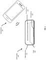
- the CGM 120is configured to use NFC communications to communicate with the wearer's smartphone 110 (or other computing device) as shown in FIG. 1 .
- the CGM 120is installed within the CGM applicator 130 , and NFC has a relatively short effective communications range, the CGM applicator 130 itself may prevent the NFC communication between the user's smartphone and the CGM 120 , simply by being a physical barrier between the smartphone and the CGM 120 that prevents the two from being positioned closely enough to enable NFC communications.
- the CGM applicator 130has an NFC coil antenna embedded within it.
- the CGM applicator's coil antenna 132can receive NFC communications from the smartphone 110 and relay them to the CGM's NFC antenna 122 .
- the CGM applicator's coil antenna 132is co-axially aligned with the CGM's coil antenna 122 .
- EMFelectromagnetic field
- the wearerlaunches an app on her smartphone 110 and selects an option to activate a new CGM.
- the appthen activates the smartphone's NFC communication system and energizes its coil antenna to generate a varying EMF. Since NFC has an effective communications range on the order of a few centimeters to a few tens of centimeters, she brings her smartphone close to the new CGM system 100 , which includes the CGM applicator 130 and the CGM 120 . She then aligns her smartphone with a coil antenna within the CGM applicator 130 , such as by visually locating the coil antenna 132 itself, or finding one or more alignment markings on the CGM applicator 130 .
- the generated EMFelectromagnetically couples the smartphone's coil antenna with the CGM applicator's coil antenna 132 .
- the CGM applicator's coil antenna 132after receiving the energy from the EMF, electromagnetically couples with the CGM's coil antenna 122 and transfers the energy to the CGM using the electromagnetic coupling.
- the varying EMF field generated by the wearer's smartphone 110includes an activation command that is propagated to the CGM 120 via the coil antennas as discussed above.
- the CGM 120activates and transmits a confirmation to the smartphone 110 using the same propagation technique, but in reverse from the CGM 120 back to the smartphone 110 .
- the appUpon receiving the confirmation from the CGM 120 , the app presents a notification to the wearer that the CGM 120 was successfully activated.
- the wearerAfter receiving confirmation that the CGM 120 has been activated, the wearer then uses the CGM applicator 130 to apply the CGM 120 to her body and affix it to her skin. She then discards the CGM applicator 130 , leaving the CGM 120 in place.
- the CGM applicator 130 in this exampleenables NFC communications between the wearer's smartphone 110 (or other computing device) and the CGM's NFC receiver by providing an intermediate coil antenna to relay EMF energy to the CGM.
- the EMF energymay be used to send commands to the CGM or to power the CGM (or both).
- the CGM applicatorenables NFC communications that might otherwise be prevented or degraded because the CGM applicator itself prevents the wearer's smartphone 110 from moving within effective communications range of the CGM's coil antenna 122 , or otherwise interferes with communication between the two.
- any suitable biosensor deviceincluding wearable biosensors, may be employed according to different examples.
- other intermediate coil configurations including multiple coilsmay be employed in some examples to extend the range of NFC communications between a smartphone (or other wireless computing device) and a receiving coil antenna.
- FIG. 2Ashows a top-down view of an example biosensor 200 usable with one or more systems or methods for enabling NFC communications with a wearable biosensor.
- the biosensor 200includes a housing 202 inside which are sensor electronics 230 , a wireless receiver 220 , and a coil antenna 210 .
- the biosensor 200includes sensor electronics 230 that include a CGM, which includes a sensor wire to be inserted into a wearer's skin to measure glucose levels within the wearer's interstitial fluid.
- the sensor electronics 230may include any suitable biosensor(s).
- one or more sensorsmay be incorporated into the biosensor 200 , including invasive or non-invasive sensors, such as analyte sensors (e.g., glucose, lactate, alcohol, etc.), blood pressure sensors, pulse sensors, blood oxygen sensors (e.g., SvO2, SpO2, etc.), galvanic skin response sensors, ultraviolet light sensors, etc.
- analyte sensorse.g., glucose, lactate, alcohol, etc.
- blood pressure sensorse.g., blood pressure sensors, pulse sensors, blood oxygen sensors (e.g., SvO2, SpO2, etc.), galvanic skin response sensors, ultraviolet light sensors, etc.
- SvO2, SpO2, etc.blood oxygen sensors
- galvanic skin response sensorse.g., ultraviolet light sensors, etc.
- the sensor electronics 230may include one or more processors, memory, a battery or other power supply (e.g., photovoltaic cells), etc.
- the sensor electronics 230are communicatively coupled with the wireless receiver 220 to allow communications between the wireless receiver 220 and the sensor electronics 230 . Communications may include data, commands, electrical power, etc. according to different examples.
- the wireless receiver 220is part of a wireless transceiver that enables wireless communications with a remote device using the coil antenna 210 ; however it should be appreciated that according to different examples, the biosensor 200 may not include a wireless transceiver, but only a wireless receiver 220 .
- the wireless receiver 220is configured to receive NFC communications; however, any suitable short-range wireless communications protocol may be employed according to different examples.
- short-rangerefers to implementations of communications techniques that have an effective range of a few centimeters (“cm”) (e.g., less than 30 cm) without intervening physical obstructions.
- the coil antenna 210is an electrical conductor, e.g., a wire or electrical trace formed on a substrate, formed in a coil shape to enable electromagnetic coupling with another coil antenna via a varying EMF and to electromagnetically couple to the receiver 220 .
- the coil antenna 210substantially planar, however, example coil antennas 210 may instead be helical.
- the coil antenna 210has a rectangular shape, suitable coil antennas may have any shape, including circular, ovoid, etc. Further, suitable coil antennas may be substantially planar or may extend along an axis, such as in a helical configuration.
- FIG. 2Bshows a side view of the biosensor 220 , which illustrates the biosensor's components within the biosensor's housing 202 .
- the receiver 220 and antenna 210are both positioned on a common substrate on a bottom portion of the biosensor housing.
- the sensor electronics 230are also physically coupled to the bottom portion of the biosensor housing 202 , however, they are occluded by the receiver 220 and antenna 210 in this view.
- the bottom portion of the housing 202refers to the portion of the housing 202 that will be positioned on or adjacent to the wearer's skin or clothing. It should be appreciated that the coil antenna 210 may be positioned at any suitable position within or on the biosensor housing 202 .
- the antenna 210may be physically coupled to the top portion of the biosensor housing 202 or on an outer surface of the biosensor housing 202 , e.g., the top portion of the biosensor housing 202 .
- the coil antenna 210may be communicatively coupled to the receiver 220 by one or more conductors, such as wires or conductive traces, e.g., conductive traces formed on the housing 202 .
- FIGS. 3A-3Cillustrate an example biosensor applicator 300 usable with systems and methods for enabling NFC communications with a wearable biosensor.
- the biosensor applicator 300has a housing 302 and two antennas 310 , 320 , and is configured to accept a biosensor within the housing 302 as will be discussed in more detail with respect to FIGS. 4A-4B below.
- FIG. 3Ashows a top-down view of the biosensor applicator 300 .
- a first antenna 310 of the two antennasis shown as positioned on the inner surface of an upper portion of the housing 302 .
- Upper portionrefers to the portion of the housing 302 opposite the portion of the housing 302 into which a biosensor may be inserted.
- the first antenna 310is positioned on an inner surface of the housing 302
- the first antenna 310may be positioned on an outer surface of the housing 302 .
- Such a configurationmay allow the wearer to more easily identify the location of the antenna 310 .
- the antenna 310has a substantially planar configuration, though in some examples, it may have a helical configuration.
- FIG. 3Bshows a top-down cross-sectional view of the interior of the biosensor applicator 300 .
- a second antenna 320is positioned within the interior of the housing 302 and is substantially axially aligned with the first coil antenna.
- each antenna 310 , 320is a coil around an axis running perpendicularly to the respective coil's plane.
- the two coils 310 , 320are positioned such that they substantially share a common central axis 312 , denoted by an ‘x’ in FIGS. 3A-3B , and by axis 312 in FIG. 3C .
- the second antenna 320in this example has a substantially planar configuration, though in some examples it may have a helical configuration.
- the antennas 310 , 320 in this exampledo not have circular cross-section, in some examples, one or both of the antennas 310 , 320 may have a substantially circular cross-section. In some examples, however, any suitable coil shape may be employed.
- FIG. 3Cshows a side cross-section of the biosensor applicator 300 .
- the applicator 300does not include a conductor physically coupling the first coil antenna 310 to the second coil antenna 310 ; however, other examples do have such a conductor, as will be discussed in more detail below.
- the two coil antennas 310 , 320are spaced apart by a distance of a few centimeters. In one example, however, the two coils are spaced apart by a distance of no more than twice a radius of the first or second coil. In some examples, one or both coils may not have a circular shape. In such examples, “radius” refers to a distance from the center axis 312 to an outer edge of the antenna 310 , 320 .
- the applicator's two coil antennas 310 , 320each have a radius of substantially 4 cm; however, any suitable radius or width may be employed. It should be appreciated, however, that an effective electromagnetic coupling distance may be up to substantially twice the radius or width of an electromagnetic coil in some examples. Therefore, a size of one or more coil antennas may be selected based on a needed effective range. For example, if distance between the biosensor coil antenna 210 and the top surface of the applicator is 6 cm, a single coil antenna, e.t., first antenna 310 , may have a radius of substantially 3 cm. Alternatively, if two coil antennas are employed, smaller radii may be employed based on the positions of the coil antennas within the applicator 300 .
- a reader device with an NFC transmitter and coil antennasuch as the smartphone 110 shown in FIG. 1
- the reader device's NFC transmitterWhen activated, it generates an alternating EMF using its coil antenna, which electromagnetically couples with the first coil antenna 310 .
- the first coil antenna 310may then electromagnetically couple with the second coil antenna 320 , effectively extending the range of the reader device's own coil antenna. Absent the first or second coil antennas 310 , 320 , the alternating EMF may not be able to effectively penetrate the applicator housing 302 to reach a biosensor within the applicator 300 .
- FIG. 4Ashows a side view of an example system 400 for enabling NFC communications with a wearable biosensor.
- the system 400includes the biosensor applicator 300 shown in FIGS. 3A-3C , and the biosensor 200 shown in FIGS. 2A-2C .
- the biosensor 200is positioned within the applicator 300 , forming a monolithic system 400 .
- the monolithic system 400can be used to apply the biosensor 200 to a wearer's skin.
- the applicator 300may include a needle to puncture the wearer's skin and to allow one or more CGM sensor wires to be inserted through the puncture.
- the biosensor 200is positioned within the applicator 300 such that the applicator's two antennas 310 , 320 sit above the biosensor 200 . And while the biosensor 200 is entirely disposed within the applicator in this example, in other examples, the biosensor 200 may partially protrude from the applicator 300 , or it may physically couple to an outer surface of the applicator's housing 302 .
- the biosensor's antenna 210is offset from the coaxially aligned antennas 310 , 320 in the applicator; however, in some examples, the biosensor's antenna 210 may be coaxially aligned with the applicator's antennas 310 , 320 .
- the biosensor's antenna 210has a smaller radius than the radii of the applicator's antennas 310 , 320 ; however, in some examples, the biosensor's antenna 210 may have substantially the same radius or a larger radius than the applicator's antenna's 310 , 320 .
- the first antenna 310is positioned on an inside of the top surface of the applicator 300 .
- a reader devicesuch as a smartphone
- the first antenna 310electromagnetically couples with the reader device's coil antenna and receives EMF energy from the reader device.
- the first antenna 310uses the received energy received to electromagnetically couple with the second antenna 320 .
- the second antenna 320then receives the EMF energy from the first antenna 310 , and uses the received EMF energy to electromagnetically couple with the biosensor's coil antenna 210 , which transfers EMF energy to the biosensor's coil antenna 210 .
- the arrangement of antennas 210 , 310 , 320 in the applicator and biosensoreffectively extend the range of the reader device's own transmission coil antenna, allowing the energy emitted by the reader device to effectively reach the biosensor's coil antenna 210 despite potentially being outside of an effective range of the transmission coil.
- an alignment marking 330is provided on the outer top surface of the applicator 300 .
- FIG. 4Bshows an example alignment marking 330 to enable a user to more easily align the reader device with the first antenna.
- the first antenna 310may be positioned on the outer top surface of the applicator 300 , or may be embedded in the top surface and made visible, e.g., via a transparent window, and such an alignment marking 330 may not be used.
- FIGS. 5A-5Cshow an example system 500 for enabling NFC communications with a wearable biosensor.
- FIG. 5Aillustrates a top-down view of a biosensor applicator 502 .
- a first antenna 510 of the applicator's two antennas 510 , 520is shown as being positioned on the inner surface of an upper portion of the applicator 502 , while a second coil antenna 520 is positioned within the interior of the applicator 502 .
- the applicator's two antennas 510 , 520are coaxially aligned with each other, substantially as described above with respect to FIGS. 3A-3C .
- the applicator's two antennasare physically and electrically coupled by an electrical conductor 530 , such as a wire or an electrical trace formed on the applicator's housing.
- the electrical conductor 530enables energy received by the first antenna 510 to be transferred to the second antenna 520 .
- the first and second antennas 510 , 520exchange energy via the electrical conductor.
- the reader device's coil antennawill electromagnetically couple with the first antenna 510 and the conductor 530 will transfer EMF energy to the first antenna 510 .
- the received energywill then traverse the electrical conductor 530 to the second antenna 520 .
- the first antenna 510will wirelessly electromagnetically couple with the second antenna 520 as well; however, the electrical conductor 530 provides a direct wired conductive pathway to transfer the energy as well.
- the second antenna 520will then electromagnetically couple with the biosensor's coil antenna 210 .
- the biosensor's coil antenna 210may then receive any commands, data, or power transmitted by the reader device.
- the applicator's two antennas 510 , 520effectively extend the range of the reader device's coil antenna.
- the electrical conductor 530may provide a more efficient pathway for energy transfer between the first and second coil antennas 510 , 520 than a wireless electromagnetic coupling. It should be appreciated that while the coil antennas 510 , 520 in this example has a substantially planar configuration, in some examples one or both may have a helical configuration.
- FIGS. 6A-6Cshow an example system 600 for enabling NFC communications with a wearable biosensor.
- FIG. 6Ashows a top-down view of a biosensor applicator 602 having a coil antenna 610 .
- the biosensor applicator 602only has one coil antenna within its housing to electromagnetically couple with a reader device and with a biosensor's antenna 210 .
- the coil antenna 610has a helical configuration rather than being substantially planar.
- the coil antenna 610is physically coupled to an inner surface of an upper portion of the applicator's housing and extends towards a bottom surface of the applicator housing along an axis. While the coil antenna 610 in this example is shown with a particular configuration having approximately five turns and a turn pitch (the axial spacing between adjacent turns) of approximately the width of the antenna's conductor, other antenna configurations may have any suitable number of turns or turn pitch.
- FIG. 6Cshows the system 600 , including the biosensor applicator 602 with an installed biosensor 200 .
- its coil antenna 610extends axially towards the biosensor 200 .
- the applicator's coil antenna 610extends to within a few millimeters (“mm”) from an upper outer surface of the biosensor 200 . Such a spacing may provide a more effective electromagnetic coupling between the applicator's coil antenna 610 and the biosensor's coil antenna 210 when the applicator's coil antenna 610 is energized.
- the biosensor's coil antenna 210is not axially aligned with the applicator's antenna 610 ; however, such an axial alignment may not be necessary in some examples.
- the energy emitted by the applicator's antenna 610may be sufficient to enable electromagnetic coupling with a misaligned antenna 210 .
- the applicator's coil antenna 610 and the biosensor's coil antenna 210may be designed to be axially aligned with the other.
- FIGS. 7A-7Bshow an example system 700 including a biosensor applicator 702 and a biosensor 200 .
- the biosensor applicator 702includes only one coil antenna 710 , which is positioned within an interior portion of the biosensor applicator 702 at a location between the applicator's upper surface 704 and the biosensor's upper surface 204 .
- the applicator's coil antenna 710is positioned equidistant between the applicator's upper surface 704 and the biosensor's upper surface 204 .
- the applicator's coil antenna 710may be positioned equidistant between the applicator's upper surface 704 and the biosensor's coil antenna 210 .
- Example applicators or similar devices according to this disclosureemploying only one coil antenna, similar to those employing two or more coil antennas as discussed above with respect to FIGS. 3A-5C , may effectively increase the effective range of an NFC or similar coil antenna in a reader device by providing an intermediate electromagnetic coupling between the reader device and a target device, such as a biosensor.
- a target devicesuch as a biosensor.
- example arrangements of one or more intermediate coil antennas, including helical antennasmay be positioned within the intervening device or applicator to enable propagation of such near-field communications from the reader device, through the intervening device, and to the coil antenna of the target device.
- Such techniquesmay enable communications through obstacles or over distances that might otherwise impair or prevent NFC communication between a reader device and a target device.
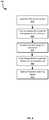
- FIG. 8shows an example method 800 for enabling NFC communications with a wearable biosensor.
- the example method 800will be discussed with respect to the example system 400 shown in FIG. 4 and the example wireless reader device 1000 shown in FIG. 10 , and described in more detail below; however any suitable system and reader device according to this disclosure may be employed.
- a reader device 1000generates an EMF using a wireless transmitter 1012 that is electrically coupled to a coil antenna 1014 .
- the reader device 1000generates a varying EMF using the transmitter 1012 according to a NFC technique; however, any suitable near-field wireless communication technique may be employed.
- the reader device 1000is brought into proximity of a device having a coil antenna.
- the deviceis a system 400 including a biosensor applicator 300 with an installed biosensor 200 .
- the biosensor applicator 300includes two coil antennas 310 , 320 .
- the reader deviceis positioned such that the first antenna 310 within the biosensor applicator 300 is within the effective range of the reader device's coil antenna 1014 , such as within a few centimeters.
- the reader device's coil antenna 1014After the reader device's coil antenna 1014 is energized by the transmitter 1012 and is generating an EMF, the reader device's coil antenna 1014 electromagnetically couples with the applicator's first antenna 310 , thereby transferring energy to the first antenna 310 .
- the applicator's first coil antenna 310uses the received energy from the reader device 1000 to electromagnetically couple with the applicator's second antenna 320 , thereby transferring energy to it. It should be appreciated that if the device does not include a second antenna, such as in the examples shown in FIGS. 6A-6 c and 7 A- 7 B, block 830 may be omitted. Further, if the device includes more than two antennas, block 830 may be repeated for each additional antenna, thereby propagating energy transmitted by the reader device 1000 through the successive coil antennas within the device.
- the second coil antenna 320uses received energy from the first antenna 310 to electromagnetically couple to the biosensor's coil antenna 210 .
- the energy received at the biosensor's coil antenna 210is then conducted to its wireless receiver 220 , where it may be used by the biosensor.
- the reader device 1000transmits a command to the biosensor using the indirect electromagnetic coupling, provided by the applicator's first and second coil antennas 310 , 320 , to the biosensor's coil antenna 210 .
- the reader device 1000transmits an activation command to the biosensor 200 .
- the activation commandis configured to cause the biosensor to activate, which may include emerging from a sleep or pre-use mode, activating a power supply within the biosensor 200 , activating one or more electronic components within the biosensor, etc.
- the biosensor 200may also transmit a response to the activation command using the indirect electromagnetic coupling between the biosensor's coil antenna 210 and the reader device's coil antenna 1014 .
- any suitable command or datamay be communicated using the indirect electromagnetic coupling between the reader device's coil antenna 1014 and the biosensor's coil antenna 210 .
- the reader device 1000may provide power to the biosensor 210 , such as to charge a battery within the biosensor 200 . In some examples, the reader device 1000 may transmit both power to charge a battery and to provide one or more commands to the biosensor.
- FIG. 9shows an example method 900 for enabling NFC communications with a wearable biosensor.
- the method 900will be discussed with respect to the example system 600 shown in FIGS. 6A-6C and the example reader device 1000 shown in FIG. 10 , discussed in more detail below; however, any suitable device system or reader device may be employed according to different examples.
- the reader device's wireless transmitter 1012generates an EMF using its coil antenna 1014 substantially as described above with respect to block 1010 .
- the reader device's coil antenna 1014electromagnetically couples to the applicator's coil antenna 610 , substantially as discussed above with respect to block 1020 .
- the applicator's coil antenna 610electromagnetically couples to the applicator's coil antenna 610 substantially as discussed above with respect to block 1040 .
- this example method 900uses only one coil within the applicator device 602 ; however, as discussed above with respect to block 830 of method 800 , any suitable number of coil antennas may be employed.
- the reader device 1000transmits a command to the biosensor 200 substantially as discussed above with respect to block 850 .
- FIG. 10shows an example computing device 1000 .
- the computing deviceincludes a processor 1010 , a memory 1020 , a wireless transceiver 1012 , a display 1030 , a user input device 1040 , and a bus 1050 .
- the computing device 1000comprises a cellular smartphone, but may be any suitable computing device, include a cellular phone, a laptop computer, a tablet, a phablet, a personal digital assistant (PDA), wearable device, etc.
- the processor 1010is configured to employ bus 1050 to execute program code stored in memory 1020 , to output display signals to a display 1030 , and to receive input from the user input module 1040 .
- the processor 1010is configured to transmit information to the wireless transceiver 1012 .
- the wireless transceiver 1012is configured to transmit and receive wireless signals via coil antenna 1014 .
- the wireless transceiver 1012may be configured to generate an EMF to electromagnetically couple the coil antenna 1014 with another coil antenna, such as may incorporated into any of the devices described above.
- a devicemay include a processor or processors.
- the processorcomprises a computer-readable medium, such as a random access memory (“RAM”) coupled to the processor.
- RAMrandom access memory
- the processorexecutes computer-executable program instructions stored in memory, such as executing one or more computer programs.
- Such processorsmay comprise a microprocessor, a digital signal processor (“DSP”), an application-specific integrated circuit (“ASIC”), field programmable gate arrays, and state machines. Such processors may further comprise programmable electronic devices such as programmable logic controllers (“PLCs”), programmable interrupt controllers (“PICs”), programmable logic devices (“PLDs”), programmable read-only memories (“PROMs”), electronically programmable read-only memories (“EPROMs” or “EEPROMs”), or other similar devices.
- PLCsprogrammable logic controllers
- PICsprogrammable interrupt controllers
- PROMsprogrammable logic devices
- PROMsprogrammable read-only memories
- EPROMselectronically programmable read-only memories
- EEPROMselectronically programmable read-only memories
- Such processorsmay comprise, or may be in communication with, media, for example computer-readable storage media, that may store instructions that, when executed by the processor, can cause the processor to perform the steps described herein as carried out, or assisted, by a processor.
- Examples of computer-readable mediamay include, but are not limited to, an electronic, optical, magnetic, or other storage device capable of providing a processor, such as the processor in a web server, with computer-readable instructions.
- Other examples of mediacomprise, but are not limited to, a floppy disk, CD-ROM, magnetic disk, memory chip, ROM, RAM, ASIC, configured processor, all optical media, all magnetic tape or other magnetic media, or any other medium from which a computer processor can read.
- the processor, and the processing, describedmay be in one or more structures, and may be dispersed through one or more structures.
- the processormay comprise code for carrying out one or more of the methods (or parts of methods) described herein.
- references herein to an example or implementationmeans that a particular feature, structure, operation, or other characteristic described in connection with the example may be included in at least one implementation of the disclosure.
- the disclosureis not restricted to the particular examples or implementations described as such.
- the appearance of the phrases “in one example,” “in an example,” “in one implementation,” or “in an implementation,” or variations of the same in various places in the specificationdoes not necessarily refer to the same example or implementation.
- Any particular feature, structure, operation, or other characteristic described in this specification in relation to one example or implementationmay be combined with other features, structures, operations, or other characteristics described in respect of any other example or implementation.
- a or B or Cincludes any or all of the following alternative combinations as appropriate for a particular usage: A alone; B alone; C alone; A and B only; A and C only; B and C only; and A and B and C.
Landscapes
- Health & Medical Sciences (AREA)
- Life Sciences & Earth Sciences (AREA)
- Engineering & Computer Science (AREA)
- Physics & Mathematics (AREA)
- Computer Networks & Wireless Communication (AREA)
- Veterinary Medicine (AREA)
- General Health & Medical Sciences (AREA)
- Public Health (AREA)
- Biophysics (AREA)
- Pathology (AREA)
- Biomedical Technology (AREA)
- Heart & Thoracic Surgery (AREA)
- Medical Informatics (AREA)
- Molecular Biology (AREA)
- Surgery (AREA)
- Animal Behavior & Ethology (AREA)
- Signal Processing (AREA)
- Optics & Photonics (AREA)
- Emergency Medicine (AREA)
- Near-Field Transmission Systems (AREA)
- Support Of Aerials (AREA)
- Measuring And Recording Apparatus For Diagnosis (AREA)
- Radar Systems Or Details Thereof (AREA)
- Measurement Of The Respiration, Hearing Ability, Form, And Blood Characteristics Of Living Organisms (AREA)
- Charge And Discharge Circuits For Batteries Or The Like (AREA)
- Arrangements For Transmission Of Measured Signals (AREA)
Abstract
Description
Claims (31)
Priority Applications (13)
| Application Number | Priority Date | Filing Date | Title |
|---|---|---|---|
| US16/528,798US11038555B2 (en) | 2018-08-06 | 2019-08-01 | Systems and methods for enabling NFC communications with a wearable biosensor |
| CN201980052442.1ACN112534515B (en) | 2018-08-06 | 2019-08-02 | Systems and methods for enabling NFC communications with wearable biosensors |
| AU2019317336AAU2019317336B2 (en) | 2018-08-06 | 2019-08-02 | Systems and methods for enabling NFC communications with a wearable biosensor |
| EP19847883.6AEP3834209B1 (en) | 2018-08-06 | 2019-08-02 | Systems and methods for enabling nfc communications with a wearable biosensor |
| PCT/US2019/044789WO2020033242A1 (en) | 2018-08-06 | 2019-08-02 | Systems and methods for enabling nfc communications with a wearable biosensor |
| CA3108329ACA3108329A1 (en) | 2018-08-06 | 2019-08-02 | Systems and methods for enabling nfc communications with a wearable biosensor |
| EP24203658.0AEP4492699A3 (en) | 2018-08-06 | 2019-08-02 | Systems and methods for enabling nfc communications with a wearable biosensor |
| CN202411602630.6ACN119483650A (en) | 2018-08-06 | 2019-08-02 | Systems and methods for enabling NFC communications with wearable biosensors |
| CN202411602559.1ACN119483649A (en) | 2018-08-06 | 2019-08-02 | Systems and methods for enabling NFC communications with wearable biosensors |
| US16/843,392US11426101B2 (en) | 2018-07-09 | 2020-04-08 | Systems and methods for sensors with multimode wireless communications and for enabling NFC communications with a wearable biosensor |
| US17/882,943US12186077B2 (en) | 2018-07-09 | 2022-08-08 | Systems and methods for sensors with multimode wireless communications and for enabling NFC communications with a wearable biosensor |
| US18/736,163US20240398287A1 (en) | 2018-07-09 | 2024-06-06 | Systems and methods for sensors with multimode wireless communications and for enabling nfc communications with a wearable biosensor |
| AU2025204756AAU2025204756A1 (en) | 2018-08-06 | 2025-06-24 | Systems and methods for enabling NFC communications with a wearable biosensor |
Applications Claiming Priority (2)
| Application Number | Priority Date | Filing Date | Title |
|---|---|---|---|
| US201862714799P | 2018-08-06 | 2018-08-06 | |
| US16/528,798US11038555B2 (en) | 2018-08-06 | 2019-08-01 | Systems and methods for enabling NFC communications with a wearable biosensor |
Related Child Applications (2)
| Application Number | Title | Priority Date | Filing Date |
|---|---|---|---|
| US201816030383AContinuation-In-Part | 2018-07-09 | 2018-07-09 | |
| US16/843,392Continuation-In-PartUS11426101B2 (en) | 2018-07-09 | 2020-04-08 | Systems and methods for sensors with multimode wireless communications and for enabling NFC communications with a wearable biosensor |
Publications (2)
| Publication Number | Publication Date |
|---|---|
| US20200044695A1 US20200044695A1 (en) | 2020-02-06 |
| US11038555B2true US11038555B2 (en) | 2021-06-15 |
Family
ID=69229194
Family Applications (1)
| Application Number | Title | Priority Date | Filing Date |
|---|---|---|---|
| US16/528,798ActiveUS11038555B2 (en) | 2018-07-09 | 2019-08-01 | Systems and methods for enabling NFC communications with a wearable biosensor |
Country Status (6)
| Country | Link |
|---|---|
| US (1) | US11038555B2 (en) |
| EP (2) | EP3834209B1 (en) |
| CN (3) | CN112534515B (en) |
| AU (2) | AU2019317336B2 (en) |
| CA (1) | CA3108329A1 (en) |
| WO (1) | WO2020033242A1 (en) |
Cited By (2)
| Publication number | Priority date | Publication date | Assignee | Title |
|---|---|---|---|---|
| US20210376881A1 (en)* | 2020-05-29 | 2021-12-02 | Shure Acquisition Holdings, Inc. | Wearable Device With Conductive Coil for Wireless Charging and Communicating |
| US12418946B2 (en)* | 2020-08-31 | 2025-09-16 | Huawei Technologies Co., Ltd. | Bluetooth communication method and electronic device |
Families Citing this family (8)
| Publication number | Priority date | Publication date | Assignee | Title |
|---|---|---|---|---|
| US11426101B2 (en) | 2018-07-09 | 2022-08-30 | Verily Life Sciences Llc | Systems and methods for sensors with multimode wireless communications and for enabling NFC communications with a wearable biosensor |
| CN112448138B (en)* | 2019-08-30 | 2023-06-13 | 光宝电子(广州)有限公司 | NFC antenna structure and its NFC circuit board and wireless charging stand |
| GB2591434B (en) | 2019-10-29 | 2022-04-20 | Prevayl Innovations Ltd | Wearable article, textile article and method |
| GB2585728B (en)* | 2020-01-21 | 2021-08-18 | Prevayl Ltd | Electronics module for a wearable article |
| GB2596932B (en)* | 2020-01-21 | 2023-02-15 | Prevayl Innovations Ltd | Electronics module for a wearable article |
| GB2611457B (en)* | 2020-01-21 | 2023-10-25 | Prevayl Innovations Ltd | Electronics module for a wearable article |
| GB2611459B (en)* | 2020-01-21 | 2023-10-25 | Prevayl Innovations Ltd | Electronics module for a wearable article |
| CN114843778A (en)* | 2022-05-31 | 2022-08-02 | 维沃移动通信有限公司 | Wearables |
Citations (46)
| Publication number | Priority date | Publication date | Assignee | Title |
|---|---|---|---|---|
| US20030012566A1 (en) | 2001-07-10 | 2003-01-16 | Takeshi Kindaichi | Electronic pickup camera and control method of electronic pickup camera |
| US20030050009A1 (en) | 2001-09-12 | 2003-03-13 | Kurisko Mark A. | Security apparatus and method during BLUETOOTH pairing |
| US7031945B1 (en) | 2000-07-24 | 2006-04-18 | Donner Irah H | System and method for reallocating and/or upgrading and/or rewarding tickets, other event admittance means, goods and/or services |
| US20060173260A1 (en) | 2005-01-31 | 2006-08-03 | Gmms Ltd | System, device and method for diabetes treatment and monitoring |
| US20070008139A1 (en) | 2005-06-14 | 2007-01-11 | Mikko Saarisalo | Tag multiplication |
| CA2553507A1 (en) | 2005-08-02 | 2007-02-02 | Research In Motion Limited | Vibratory data communication between devices |
| US20080116847A1 (en) | 2006-09-01 | 2008-05-22 | Bio Aim Technologies Holding Ltd. | Systems and methods for wireless power transfer |
| CN101193671A (en) | 2005-04-26 | 2008-06-04 | 迪斯特朗尼克许可公司 | Energy-optimised data transmission for a medical appliance |
| US20100045425A1 (en) | 2008-08-21 | 2010-02-25 | Chivallier M Laurent | data transmission of sensors |
| US20100148723A1 (en) | 2008-09-02 | 2010-06-17 | Qualcomm Incorporated | Bidirectional wireless power transmission |
| US20100292556A1 (en) | 2009-05-12 | 2010-11-18 | Michael Golden | Methods and systems for managing, controlling and monitoring medical devices via one or more software applications functioning in a secure environment |
| US20110022411A1 (en) | 2008-03-19 | 2011-01-27 | Telefonaktiebolaget Lm Ericsson (Publ) | NFC Communications for Implanted Medical Data Acquisition Devices |
| US20110046548A1 (en) | 2008-04-24 | 2011-02-24 | Arkray,Inc | Blood sugar level control system |
| US20110221590A1 (en) | 2010-03-15 | 2011-09-15 | Welch Allyn, Inc. | Personal Area Network Pairing |
| US20120003933A1 (en) | 2010-06-30 | 2012-01-05 | Welch Allyn, Inc. | Medical devices with proximity detection |
| US20120028575A1 (en) | 2010-07-28 | 2012-02-02 | Mstar Semiconductor, Inc. | Power Supply control Apparatus and Method Thereof and Mobile Apparatus Using the same |
| US20130029596A1 (en) | 2011-07-29 | 2013-01-31 | Motorola Solutions, Inc. | Pairing devices using data exchanged in an out-of-band channel |
| US20130069753A1 (en) | 2011-09-16 | 2013-03-21 | Witricity Corporation | High frequency pcb coils |
| WO2013063634A1 (en) | 2011-10-31 | 2013-05-10 | Ait Austrian Institute Of Technology Gmbh | Measurement device for measuring glucose |
| US20130217979A1 (en) | 2011-12-02 | 2013-08-22 | Thomas P. Blackadar | Versatile sensors with data fusion functionality |
| US20130274629A1 (en)* | 2012-04-12 | 2013-10-17 | Elwha LLC a limited liability company of the State of Delaware | Appurtenances for reporting information regarding wound dressings |
| US20140138432A1 (en) | 2012-11-16 | 2014-05-22 | Electronics And Telecommunications Research Institute | Sensor tag and method of providing service using the same |
| US20140184422A1 (en) | 2012-12-31 | 2014-07-03 | Dexcom, Inc. | Remote monitoring of analyte measurements |
| US8798541B1 (en) | 2011-04-11 | 2014-08-05 | Vmware, Inc. | System and method for socket backed host controller interface emulation for virtual bluetooth adapter |
| US20140273821A1 (en) | 2013-03-14 | 2014-09-18 | Dexcom, Inc. | Systems and methods for processing and transmitting sensor data |
| US20140313052A1 (en) | 2011-12-15 | 2014-10-23 | Becton, Dickinson And Company | Near Field Telemetry Link for Passing a Shared Secret to Establish a Secure Radio Frequency Communication Link in a Physiological Condition Monitoring System |
| US20150018643A1 (en) | 2013-04-30 | 2015-01-15 | Abbott Diabetes Care Inc. | Systems, devices, and methods for energy efficient electrical device activation |
| US20150054621A1 (en) | 2013-08-22 | 2015-02-26 | Google Inc. | Using Unique Identifiers to Retrieve Configuration Data for Tag Devices |
| US20150075770A1 (en) | 2013-05-31 | 2015-03-19 | Michael Linley Fripp | Wireless activation of wellbore tools |
| US20150343144A1 (en) | 2014-06-03 | 2015-12-03 | Pop Test LLC | Drug Device Configured for Wireless Communication |
| US20160015267A1 (en) | 2009-08-31 | 2016-01-21 | Abbott Diabetes Care Inc. | Medical Devices and Methods |
| US9246555B2 (en) | 2009-09-24 | 2016-01-26 | Blackberry Limited | System and associated NFC tag using plurality of NFC tags associated with location or devices to communicate with communications device |
| WO2016081244A1 (en) | 2014-11-18 | 2016-05-26 | Mc10, Inc. | System, device, and method for electronic device activation |
| US20160183854A1 (en)* | 2014-11-25 | 2016-06-30 | Abbott Diabetes Care Inc. | Analyte monitoring systems, devices, and methods |
| US20160242685A1 (en) | 2015-02-24 | 2016-08-25 | Senseonics, Incorporated | Analyte sensor |
| US20160310663A1 (en)* | 2015-04-27 | 2016-10-27 | Qualcomm Incorporated | Subcutaneous injection system with adhesive injection site indicator |
| US20160331283A1 (en) | 2015-05-14 | 2016-11-17 | Abbott Diabetes Care Inc. | Systems, devices, and methods for assembling an applicator and sensor control device |
| US20160331232A1 (en) | 2015-05-14 | 2016-11-17 | Abbott Diabetes Care Inc. | Systems, devices, and methods for monitoring medical devices |
| US20170040818A1 (en) | 2015-08-07 | 2017-02-09 | Samsung Electronics Co., Ltd. | Charge control circuit using battery voltage tracking, and a device having the same |
| US20170047636A1 (en) | 2015-08-10 | 2017-02-16 | Samsung Electronics Co., Ltd. | Antenna structure and electronic device including the same |
| US20170079587A1 (en)* | 2015-09-22 | 2017-03-23 | Johnson & Johnson Consumer Inc. | Vaginal ring sensor |
| US20170173262A1 (en) | 2017-03-01 | 2017-06-22 | François Paul VELTZ | Medical systems, devices and methods |
| US20170185284A1 (en) | 2015-12-28 | 2017-06-29 | Dexcom, Inc. | Wearable apparatus for continuous blood glucose monitoring |
| US20170337461A1 (en)* | 2014-11-07 | 2017-11-23 | 3M Innovative Properties Company | Wireless sensor for thermal property with thermal source |
| US20180026678A1 (en) | 2016-07-25 | 2018-01-25 | Verily Life Sciences Llc | Systems and methods for passive radio enabled power gating for a body mountable device |
| US20180192514A1 (en)* | 2015-08-21 | 2018-07-05 | Amogreentech Co., Ltd. | Wearable flexible printed circuit board and method of manufacturing the same |
Family Cites Families (4)
| Publication number | Priority date | Publication date | Assignee | Title |
|---|---|---|---|---|
| CN104548344B (en)* | 2015-01-16 | 2017-02-22 | 江苏科技大学 | Injection type nerve stimulator with power supplied by radio frequency energy |
| RU2018101297A (en)* | 2015-06-15 | 2019-07-15 | Поготек, Инк. | WIRELESS POWER SYSTEMS AND METHODS SUITABLE FOR CHARGING WEARABLE ELECTRONIC DEVICES |
| JP6466624B2 (en)* | 2015-09-03 | 2019-02-06 | コーニンクレッカ フィリップス エヌ ヴェKoninklijke Philips N.V. | Cable unit for connecting devices and enabling wireless exchange of data and / or power between devices |
| EP3563224B1 (en)* | 2016-12-27 | 2023-12-20 | Dexcom, Inc. | Systems and methods for patient monitoring using an hcp - specific device |
- 2019
- 2019-08-01USUS16/528,798patent/US11038555B2/enactiveActive
- 2019-08-02AUAU2019317336Apatent/AU2019317336B2/enactiveActive
- 2019-08-02CACA3108329Apatent/CA3108329A1/enactivePending
- 2019-08-02CNCN201980052442.1Apatent/CN112534515B/enactiveActive
- 2019-08-02WOPCT/US2019/044789patent/WO2020033242A1/ennot_activeCeased
- 2019-08-02CNCN202411602630.6Apatent/CN119483650A/enactivePending
- 2019-08-02EPEP19847883.6Apatent/EP3834209B1/enactiveActive
- 2019-08-02CNCN202411602559.1Apatent/CN119483649A/enactivePending
- 2019-08-02EPEP24203658.0Apatent/EP4492699A3/enactivePending
- 2025
- 2025-06-24AUAU2025204756Apatent/AU2025204756A1/enactivePending
Patent Citations (56)
| Publication number | Priority date | Publication date | Assignee | Title |
|---|---|---|---|---|
| US7031945B1 (en) | 2000-07-24 | 2006-04-18 | Donner Irah H | System and method for reallocating and/or upgrading and/or rewarding tickets, other event admittance means, goods and/or services |
| US20030012566A1 (en) | 2001-07-10 | 2003-01-16 | Takeshi Kindaichi | Electronic pickup camera and control method of electronic pickup camera |
| US20030050009A1 (en) | 2001-09-12 | 2003-03-13 | Kurisko Mark A. | Security apparatus and method during BLUETOOTH pairing |
| US20060173260A1 (en) | 2005-01-31 | 2006-08-03 | Gmms Ltd | System, device and method for diabetes treatment and monitoring |
| CN101193671A (en) | 2005-04-26 | 2008-06-04 | 迪斯特朗尼克许可公司 | Energy-optimised data transmission for a medical appliance |
| US20070008139A1 (en) | 2005-06-14 | 2007-01-11 | Mikko Saarisalo | Tag multiplication |
| CA2553507A1 (en) | 2005-08-02 | 2007-02-02 | Research In Motion Limited | Vibratory data communication between devices |
| US20080116847A1 (en) | 2006-09-01 | 2008-05-22 | Bio Aim Technologies Holding Ltd. | Systems and methods for wireless power transfer |
| US20110022411A1 (en) | 2008-03-19 | 2011-01-27 | Telefonaktiebolaget Lm Ericsson (Publ) | NFC Communications for Implanted Medical Data Acquisition Devices |
| US20110046548A1 (en) | 2008-04-24 | 2011-02-24 | Arkray,Inc | Blood sugar level control system |
| US20100045425A1 (en) | 2008-08-21 | 2010-02-25 | Chivallier M Laurent | data transmission of sensors |
| US20100148723A1 (en) | 2008-09-02 | 2010-06-17 | Qualcomm Incorporated | Bidirectional wireless power transmission |
| US8947041B2 (en) | 2008-09-02 | 2015-02-03 | Qualcomm Incorporated | Bidirectional wireless power transmission |
| CN102144239A (en) | 2008-09-02 | 2011-08-03 | 高通股份有限公司 | Bidirectional wireless power transmission |
| US20100292556A1 (en) | 2009-05-12 | 2010-11-18 | Michael Golden | Methods and systems for managing, controlling and monitoring medical devices via one or more software applications functioning in a secure environment |
| US20160015267A1 (en) | 2009-08-31 | 2016-01-21 | Abbott Diabetes Care Inc. | Medical Devices and Methods |
| CN105686807A (en) | 2009-08-31 | 2016-06-22 | 雅培糖尿病护理公司 | Medical devices |
| US9246555B2 (en) | 2009-09-24 | 2016-01-26 | Blackberry Limited | System and associated NFC tag using plurality of NFC tags associated with location or devices to communicate with communications device |
| US20110221590A1 (en) | 2010-03-15 | 2011-09-15 | Welch Allyn, Inc. | Personal Area Network Pairing |
| US20120003933A1 (en) | 2010-06-30 | 2012-01-05 | Welch Allyn, Inc. | Medical devices with proximity detection |
| US20120028575A1 (en) | 2010-07-28 | 2012-02-02 | Mstar Semiconductor, Inc. | Power Supply control Apparatus and Method Thereof and Mobile Apparatus Using the same |
| US8798541B1 (en) | 2011-04-11 | 2014-08-05 | Vmware, Inc. | System and method for socket backed host controller interface emulation for virtual bluetooth adapter |
| US20130029596A1 (en) | 2011-07-29 | 2013-01-31 | Motorola Solutions, Inc. | Pairing devices using data exchanged in an out-of-band channel |
| US20130069753A1 (en) | 2011-09-16 | 2013-03-21 | Witricity Corporation | High frequency pcb coils |
| WO2013063634A1 (en) | 2011-10-31 | 2013-05-10 | Ait Austrian Institute Of Technology Gmbh | Measurement device for measuring glucose |
| US20130217979A1 (en) | 2011-12-02 | 2013-08-22 | Thomas P. Blackadar | Versatile sensors with data fusion functionality |
| US20140313052A1 (en) | 2011-12-15 | 2014-10-23 | Becton, Dickinson And Company | Near Field Telemetry Link for Passing a Shared Secret to Establish a Secure Radio Frequency Communication Link in a Physiological Condition Monitoring System |
| CN204576485U (en) | 2011-12-15 | 2015-08-19 | 贝克顿·迪金森公司 | Physiological condition surveillance, physiological condition sensor and physiological condition instrument |
| US20130274629A1 (en)* | 2012-04-12 | 2013-10-17 | Elwha LLC a limited liability company of the State of Delaware | Appurtenances for reporting information regarding wound dressings |
| US20140138432A1 (en) | 2012-11-16 | 2014-05-22 | Electronics And Telecommunications Research Institute | Sensor tag and method of providing service using the same |
| US9110897B2 (en) | 2012-11-16 | 2015-08-18 | Electronics And Telecommunications Research Institute | Sensor tag and method of providing service using the same |
| US20140184422A1 (en) | 2012-12-31 | 2014-07-03 | Dexcom, Inc. | Remote monitoring of analyte measurements |
| US20140273821A1 (en) | 2013-03-14 | 2014-09-18 | Dexcom, Inc. | Systems and methods for processing and transmitting sensor data |
| US20150018643A1 (en) | 2013-04-30 | 2015-01-15 | Abbott Diabetes Care Inc. | Systems, devices, and methods for energy efficient electrical device activation |
| US20150075770A1 (en) | 2013-05-31 | 2015-03-19 | Michael Linley Fripp | Wireless activation of wellbore tools |
| US20150054621A1 (en) | 2013-08-22 | 2015-02-26 | Google Inc. | Using Unique Identifiers to Retrieve Configuration Data for Tag Devices |
| US20150343144A1 (en) | 2014-06-03 | 2015-12-03 | Pop Test LLC | Drug Device Configured for Wireless Communication |
| US20170337461A1 (en)* | 2014-11-07 | 2017-11-23 | 3M Innovative Properties Company | Wireless sensor for thermal property with thermal source |
| WO2016081244A1 (en) | 2014-11-18 | 2016-05-26 | Mc10, Inc. | System, device, and method for electronic device activation |
| US20160183854A1 (en)* | 2014-11-25 | 2016-06-30 | Abbott Diabetes Care Inc. | Analyte monitoring systems, devices, and methods |
| US20160242685A1 (en) | 2015-02-24 | 2016-08-25 | Senseonics, Incorporated | Analyte sensor |
| US9901293B2 (en) | 2015-02-24 | 2018-02-27 | Senseonics, Incorporated | Analyte sensor |
| US20160310663A1 (en)* | 2015-04-27 | 2016-10-27 | Qualcomm Incorporated | Subcutaneous injection system with adhesive injection site indicator |
| US20160331232A1 (en) | 2015-05-14 | 2016-11-17 | Abbott Diabetes Care Inc. | Systems, devices, and methods for monitoring medical devices |
| US20180199813A1 (en) | 2015-05-14 | 2018-07-19 | Abbott Diabetes Care Inc. | Systems, devices, and methods for monitoring medical devices |
| US20160331283A1 (en) | 2015-05-14 | 2016-11-17 | Abbott Diabetes Care Inc. | Systems, devices, and methods for assembling an applicator and sensor control device |
| US20170040818A1 (en) | 2015-08-07 | 2017-02-09 | Samsung Electronics Co., Ltd. | Charge control circuit using battery voltage tracking, and a device having the same |
| US20170047636A1 (en) | 2015-08-10 | 2017-02-16 | Samsung Electronics Co., Ltd. | Antenna structure and electronic device including the same |
| US20180192514A1 (en)* | 2015-08-21 | 2018-07-05 | Amogreentech Co., Ltd. | Wearable flexible printed circuit board and method of manufacturing the same |
| US20170079587A1 (en)* | 2015-09-22 | 2017-03-23 | Johnson & Johnson Consumer Inc. | Vaginal ring sensor |
| US20170185284A1 (en) | 2015-12-28 | 2017-06-29 | Dexcom, Inc. | Wearable apparatus for continuous blood glucose monitoring |
| US20180026678A1 (en) | 2016-07-25 | 2018-01-25 | Verily Life Sciences Llc | Systems and methods for passive radio enabled power gating for a body mountable device |
| WO2018022235A1 (en) | 2016-07-25 | 2018-02-01 | Verily Life Sciences Llc | Systems and methods for passive radio enabled power gating for a body mountable device |
| US9967001B2 (en) | 2016-07-25 | 2018-05-08 | Verily Life Sciences Llc | Systems and methods for passive radio enabled power gating for a body mountable device |
| US20180234133A1 (en) | 2016-07-25 | 2018-08-16 | Verily Life Sciences Llc | Systems and methods for passive radio enabled power gating for a body mountable device |
| US20170173262A1 (en) | 2017-03-01 | 2017-06-22 | François Paul VELTZ | Medical systems, devices and methods |
Non-Patent Citations (21)
| Title |
|---|
| "NFC Antenna : Add-on for your NFC Patch", <https://flomio.com/shop/readers/nfc-antenna/> downloaded Oct. 14, 2019. |
| "NFC Patch Kit : Extend your NFC reach", <https://flomio.com/shop/nfc-readers/nfc-patch-kit/> downloaded Oct. 14, 2019. |
| Chinese Application No. CN201780046360.7 , Notice of Decision to Grant, dated Jul. 3, 2020, 2 pages. |
| Chinese Application No. CN201780046360.7 , Office Action, dated Nov. 11, 2019, 9 pages. |
| International Application No. PCT/U52017/039380 , International Preliminary Report on Patentability, dated Feb. 7, 2019, 8 pages. |
| International Application No. PCT/U52017/039380 , International Search Report and Written Opinion, dated Sep. 7, 2017, 11 pages. |
| International Application No. PCT/US2019/044789 , International Search Report and Written Opinion, dated Nov. 7, 2019, 12 pages. |
| Jara et al., "Communication Protocol for Enabling Continuous Monitoring of Elderly People through Near Field Communications", Interacting with Computers, May 15, 2013, 2 pages. |
| U.S. Appl. No. 15/218,587 , Advisory Action, dated Oct. 5, 2017, 3 pages. |
| U.S. Appl. No. 15/218,587 , Final Office Action, dated Jul. 24, 2017, 16 pages. |
| U.S. Appl. No. 15/218,587 , Non-Final Office Action, dated Jan. 12, 2017, 13 pages. |
| U.S. Appl. No. 15/218,587 , Notice of Allowance, dated Jan. 10, 2018, 8 pages. |
| U.S. Appl. No. 15/945,286 , Advisory Action, dated Feb. 7, 2019, 3 pages. |
| U.S. Appl. No. 15/945,286 , Final Office Action, dated Nov. 2, 2018, 19 pages. |
| U.S. Appl. No. 15/945,286 , Non Final Office Action, dated Jun. 4, 2018, 17 Pages. |
| U.S. Appl. No. 16/030,383 , Advisory Action, dated Apr. 12, 2019, 5 pages. |
| U.S. Appl. No. 16/030,383 , Advisory Action, dated Feb. 19, 2020, 3 pages. |
| U.S. Appl. No. 16/030,383 , Final Office Action, dated Feb. 8, 2019, 26 pages. |
| U.S. Appl. No. 16/030,383 , Final Office Action, dated Nov. 19, 2019, 25 pages. |
| U.S. Appl. No. 16/030,383 , Non-Final Office Action, dated Jul. 12, 2019, 24 pages. |
| U.S. Appl. No. 16/030,383 , Non-Final Office Action, dated Oct. 9, 2018, 22 pages. |
Cited By (2)
| Publication number | Priority date | Publication date | Assignee | Title |
|---|---|---|---|---|
| US20210376881A1 (en)* | 2020-05-29 | 2021-12-02 | Shure Acquisition Holdings, Inc. | Wearable Device With Conductive Coil for Wireless Charging and Communicating |
| US12418946B2 (en)* | 2020-08-31 | 2025-09-16 | Huawei Technologies Co., Ltd. | Bluetooth communication method and electronic device |
Also Published As
| Publication number | Publication date |
|---|---|
| EP3834209A1 (en) | 2021-06-16 |
| AU2019317336A1 (en) | 2021-01-28 |
| WO2020033242A1 (en) | 2020-02-13 |
| US20200044695A1 (en) | 2020-02-06 |
| CN112534515A (en) | 2021-03-19 |
| CN119483650A (en) | 2025-02-18 |
| EP4492699A2 (en) | 2025-01-15 |
| EP3834209A4 (en) | 2022-05-04 |
| AU2019317336B2 (en) | 2025-03-27 |
| CN112534515B (en) | 2024-12-06 |
| EP4492699A3 (en) | 2025-03-26 |
| CA3108329A1 (en) | 2020-02-13 |
| AU2025204756A1 (en) | 2025-07-10 |
| EP3834209B1 (en) | 2024-10-02 |
| CN119483649A (en) | 2025-02-18 |
Similar Documents
| Publication | Publication Date | Title |
|---|---|---|
| US11038555B2 (en) | Systems and methods for enabling NFC communications with a wearable biosensor | |
| US12186077B2 (en) | Systems and methods for sensors with multimode wireless communications and for enabling NFC communications with a wearable biosensor | |
| US20220126104A1 (en) | Antennas for small imds | |
| US12009580B2 (en) | Antenna configuration for compact glucose monitor | |
| US8417340B2 (en) | Implant with antenna array | |
| US10742269B2 (en) | Systems, devices, and methods utilizing secondary communication systems | |
| EP3342056B1 (en) | Internal coil structure and method for operating the same in a wireless terminal | |
| KR102506711B1 (en) | Antenna structure and electronic device comprising thereof | |
| KR20160131696A (en) | Antenna and electronic device comprising thereof | |
| US10868584B2 (en) | Antenna device and electronic device including same | |
| US10511192B2 (en) | Wireless power receiver | |
| US20230006337A1 (en) | Wearable electronic device including an overlapping communications antenna | |
| AU2021403095B2 (en) | Battery antenna arrangement for an on body medical device | |
| KR20230081634A (en) | Relay apparatus in form of accessory and relay method capable of extending recognition distance of rfid and/or nfc of smart device | |
| TWM602732U (en) | Physiological signal detection and transmission device and antenna module |
Legal Events
| Date | Code | Title | Description |
|---|---|---|---|
| FEPP | Fee payment procedure | Free format text:ENTITY STATUS SET TO UNDISCOUNTED (ORIGINAL EVENT CODE: BIG.); ENTITY STATUS OF PATENT OWNER: LARGE ENTITY | |
| AS | Assignment | Owner name:VERILY LIFE SCIENCES LLC, CALIFORNIA Free format text:ASSIGNMENT OF ASSIGNORS INTEREST;ASSIGNORS:BIEDERMAN, WILLIAM;RAM RAKHYANI, ANIL KUMAR;JUNG, LOUIS;AND OTHERS;SIGNING DATES FROM 20190801 TO 20190807;REEL/FRAME:050269/0950 | |
| STPP | Information on status: patent application and granting procedure in general | Free format text:DOCKETED NEW CASE - READY FOR EXAMINATION | |
| STPP | Information on status: patent application and granting procedure in general | Free format text:NON FINAL ACTION MAILED | |
| STPP | Information on status: patent application and granting procedure in general | Free format text:NOTICE OF ALLOWANCE MAILED -- APPLICATION RECEIVED IN OFFICE OF PUBLICATIONS | |
| STPP | Information on status: patent application and granting procedure in general | Free format text:AWAITING TC RESP., ISSUE FEE NOT PAID | |
| STPP | Information on status: patent application and granting procedure in general | Free format text:NOTICE OF ALLOWANCE MAILED -- APPLICATION RECEIVED IN OFFICE OF PUBLICATIONS | |
| STPP | Information on status: patent application and granting procedure in general | Free format text:PUBLICATIONS -- ISSUE FEE PAYMENT RECEIVED | |
| STPP | Information on status: patent application and granting procedure in general | Free format text:PUBLICATIONS -- ISSUE FEE PAYMENT VERIFIED | |
| STCF | Information on status: patent grant | Free format text:PATENTED CASE | |
| AS | Assignment | Owner name:DEXCOM, INC., CALIFORNIA Free format text:ASSIGNMENT OF ASSIGNORS INTEREST;ASSIGNOR:VERILY LIFE SCIENCES LLC;REEL/FRAME:062887/0119 Effective date:20200305 | |
| MAFP | Maintenance fee payment | Free format text:PAYMENT OF MAINTENANCE FEE, 4TH YEAR, LARGE ENTITY (ORIGINAL EVENT CODE: M1551); ENTITY STATUS OF PATENT OWNER: LARGE ENTITY Year of fee payment:4 |