US11038278B2 - Lens apparatus and methods for an antenna - Google Patents
Lens apparatus and methods for an antennaDownload PDFInfo
- Publication number
- US11038278B2 US11038278B2US16/541,569US201916541569AUS11038278B2US 11038278 B2US11038278 B2US 11038278B2US 201916541569 AUS201916541569 AUS 201916541569AUS 11038278 B2US11038278 B2US 11038278B2
- Authority
- US
- United States
- Prior art keywords
- antenna
- lens
- feed
- dielectric material
- dual
- Prior art date
- Legal status (The legal status is an assumption and is not a legal conclusion. Google has not performed a legal analysis and makes no representation as to the accuracy of the status listed.)
- Active, expires
Links
- 238000000034methodMethods0.000titledescription12
- 230000008878couplingEffects0.000claimsdescription24
- 238000010168coupling processMethods0.000claimsdescription24
- 238000005859coupling reactionMethods0.000claimsdescription24
- 239000011800void materialSubstances0.000claimsdescription6
- 239000004743PolypropyleneSubstances0.000claimsdescription3
- -1polypropylenePolymers0.000claimsdescription3
- 229920001155polypropylenePolymers0.000claimsdescription3
- 239000003989dielectric materialSubstances0.000claims13
- 229910003460diamondInorganic materials0.000claims2
- 239000010432diamondSubstances0.000claims2
- 238000010586diagramMethods0.000description22
- 239000000463materialSubstances0.000description15
- 238000012360testing methodMethods0.000description7
- 230000005855radiationEffects0.000description4
- 230000005540biological transmissionEffects0.000description2
- 238000004519manufacturing processMethods0.000description2
- 238000010420art techniqueMethods0.000description1
- 238000004891communicationMethods0.000description1
- 239000012141concentrateSubstances0.000description1
- 238000005259measurementMethods0.000description1
- 238000012545processingMethods0.000description1
- 238000011160researchMethods0.000description1
- 238000012827research and developmentMethods0.000description1
- 238000001228spectrumMethods0.000description1
- 238000010998test methodMethods0.000description1
- 238000012546transferMethods0.000description1
Images


Classifications
- H—ELECTRICITY
- H01—ELECTRIC ELEMENTS
- H01Q—ANTENNAS, i.e. RADIO AERIALS
- H01Q15/00—Devices for reflection, refraction, diffraction or polarisation of waves radiated from an antenna, e.g. quasi-optical devices
- H01Q15/02—Refracting or diffracting devices, e.g. lens, prism
- H—ELECTRICITY
- H01—ELECTRIC ELEMENTS
- H01Q—ANTENNAS, i.e. RADIO AERIALS
- H01Q15/00—Devices for reflection, refraction, diffraction or polarisation of waves radiated from an antenna, e.g. quasi-optical devices
- H01Q15/02—Refracting or diffracting devices, e.g. lens, prism
- H01Q15/08—Refracting or diffracting devices, e.g. lens, prism formed of solid dielectric material
- H—ELECTRICITY
- H01—ELECTRIC ELEMENTS
- H01Q—ANTENNAS, i.e. RADIO AERIALS
- H01Q9/00—Electrically-short antennas having dimensions not more than twice the operating wavelength and consisting of conductive active radiating elements
- H01Q9/04—Resonant antennas
- H01Q9/16—Resonant antennas with feed intermediate between the extremities of the antenna, e.g. centre-fed dipole
- H01Q9/28—Conical, cylindrical, cage, strip, gauze, or like elements having an extended radiating surface; Elements comprising two conical surfaces having collinear axes and adjacent apices and fed by two-conductor transmission lines
Definitions
- the present disclosuretechnically relates to antennas.
- the present disclosuretechnically relates to apparatuses for improving antenna performance.
- FIG. 1this diagram illustrates, in a side view, an antenna A, in accordance with the prior art.
- the antenna Atypically comprises an upper antenna element 30 , a lower antenna element 40 , and a feed 50 from the lower antenna element 40 to the upper antenna element 30 .
- the antenna Ahas an antenna gain G that equals a directivity D of the antenna A multiplied by an efficiency E of the antenna A.
- the antenna efficiency Eis the ability of the antenna A to transfer energy from a feed 50 , such as a radio-frequency (RF) cable or a feed cable, to the antenna A, including energy absorbed by the antenna A, itself, if the antenna A experiences any losses.
- RFradio-frequency
- Related art techniquesuse multiple antennas to achieve improvement in antenna gain, thereby resulting in undue weight and complexity. Further, related art lens antennas only improve antenna gain in one particular direction. Challenges experienced in the related art include limited performance, e.g., limited gain and limited directionality, e.g., related art directional antennas, wherein electromagnetic energy is directed towards only a specific direction. Therefore, a need exists in the related art for the improving antenna performance, such as by improving antenna gain in all directions.
- the present disclosureinvolves a lens apparatus for improving antenna performance, the apparatus comprising: a lens configured to at least one of focus, refocus, and refract electromagnetic energy for constructively adding gain in a far-field, the lens configured to operably couple with an antenna, whereby electromagnetic energy is omnidirectionally concentrated, whereby antenna gain and directivity are improved, whereby antenna efficiency and antenna frequency range are maintained, and whereby antenna complexity is minimized, in accordance with an embodiment of the present disclosure.
- FIG. 1is a diagram illustrating a side view of an antenna, in accordance with the prior art.
- FIG. 2Ais a diagram illustrating a side view of a lens apparatus, comprising lens, such as a convex lens, operably coupled with an antenna, such as a bicone antenna, in accordance with an embodiment of the present disclosure.
- lenssuch as a convex lens
- antennasuch as a bicone antenna
- FIG. 2Bis a diagram illustrating a cross-sectional side view of a lens apparatus, comprising a lens, such as a convex lens, operably coupled with an antenna, such as a bicone antenna, wherein the lens performs at least one of focus, refocus, and refract electromagnetic energy, as shown in FIG. 2A , in accordance with an embodiment of the present disclosure.
- a lenssuch as a convex lens
- an antennasuch as a bicone antenna
- FIG. 3Ais a diagram illustrating a cross-sectional side view of a lens apparatus, comprising a lens, such as a convex lens, operably coupled with an antenna, such as a bicone antenna having a feed and a coupling feature, shown by an inset view, wherein the lens performs at least one of focus, refocus, and refract electromagnetic energy, in accordance with an embodiment of the present disclosure.
- a lenssuch as a convex lens
- an antennasuch as a bicone antenna having a feed and a coupling feature, shown by an inset view, wherein the lens performs at least one of focus, refocus, and refract electromagnetic energy, in accordance with an embodiment of the present disclosure.
- FIG. 3Bis a diagram illustrating a cross-sectional side view of the coupling feature in the inset view, as shown in FIG. 3A , in accordance with an embodiment of the present disclosure.
- FIG. 4is a diagram illustrating a cross-sectional side view of a lens apparatus having a void, shown with example dimensions, in accordance with an embodiment of the present disclosure.
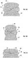
- FIG. 5Ais a diagram illustrating a side view of an improved antenna radiation pattern effected by, and exemplifying low frequency performance of, a lens apparatus, in accordance with an embodiment of the present disclosure.
- FIG. 5Bis a diagram illustrating a side view of an improved antenna radiation pattern effected by, and exemplifying high frequency performance of, a lens apparatus, in accordance with an embodiment of the present disclosure.
- FIG. 5Cis a diagram illustrating a side view of an improved antenna radiation pattern 105 c effected by, and exemplifying very high frequency performance of, a lens apparatus, in accordance with an embodiment of the present disclosure.
- FIG. 6is a graph illustrating a simulated antenna gain, as a function of frequency range, at lower frequencies, of an antenna operably coupled with the general or simulated lens apparatus, in relation to a measured (at chamber) antenna gain of an antenna operably coupled with a prototype lens apparatus, in accordance with embodiments of the present disclosure.
- FIG. 7is a graph illustrating another simulated antenna gain, as a function of frequency range, at higher frequencies, of an antenna operably coupled with the general or simulated lens apparatus, in relation to a measured (at chamber) antenna gain of an antenna operably coupled with the prototype lens apparatus, in accordance with embodiments of the present disclosure.
- FIG. 8is a graph illustrating a return-loss, as a function of frequency range, of an antenna operably coupled with a lens apparatus, in accordance with embodiments of the present disclosure.
- FIG. 9Ais a diagram illustrating a cross-sectional side view of a lens apparatus that is scalable in at least one of size and shape in at least one plane, wherein the lens apparatus has an aspect ratio, for example, in accordance with an alternative embodiment of the present disclosure.
- FIG. 9Bis a diagram illustrating a cross-sectional side view of a lens apparatus, that is scalable in at least one of size and shape in at least one plane, wherein the lens apparatus has a higher aspect ratio than that shown in FIG. 13A , for example , in accordance with an alternative embodiment of the present disclosure.
- FIG. 9Cis a diagram illustrating a cross-sectional side view of a lens apparatus, that is scalable in at least one of size and shape in at least one plane, wherein the lens apparatus has a lower aspect ratio than that shown in FIG. 13A , for example, in accordance with an alternative embodiment of the present disclosure.
- FIG. 10is a diagram illustrating side views, and cross-sectional side views, of various lens apparatuses, implemented with various lens apparatuses, in accordance with various alternative embodiments of the present disclosure.
- FIG. 11is a flow diagram illustrating a method of providing a lens apparatus for improving performance of an antenna, in accordance with an embodiment of the present disclosure.
- FIG. 12is a flow diagram illustrating a method of improving performance of an antenna by way of a lens apparatus, in accordance with an embodiment of the present disclosure.
- FIGS. 2A and 2Billustrate, in a side view, a lens apparatus 100 , comprising a lens 101 and a coupling feature 102 .
- the lens apparatus 100 shown in FIGS. 2A and 2Bis operably coupled with an antenna A′, which in this embodiment is a bicone antenna, comprising an upper antenna element 30 ′ and a lower antenna element 40 ′.
- the lens 101may be configured to focus, refocus, and/or refract electromagnetic energy for constructively adding gain in a far-field.
- the lens 101is configured to operably couple with an antenna A′, whereby electromagnetic energy is omnidirectionally concentrated, whereby antenna gain and directivity are improved, whereby antenna efficiency and antenna frequency range are maintained, and whereby antenna complexity is minimized.
- the lens apparatus 100maximizes the directivity and antenna efficiency of an antenna A′ by allowing electromagnetic energy to act as a travelling wave by way of a logarithmic curve that is extended across the antenna A′ in an x-plane P x , shown in relation to a z-plane direction P z .
- the lens 101comprises at least one shape of a spheroidal shape, a convex shape, a toroidal shape, a ring toroidal shape, a horn toroidal shape, a spindle toroidal shape, a lemniscate shape, a lemnsicate of Bernoulli shape, a lemnsicate of Booth shape, lemniscate of Gerono shape, a paraboloid of revolution shape, and a hyperboloid of revolution shape, for at least one of focusing, refocusing, and refracting electromagnetic energy being radiated from the antenna A′ in the far-field, thereby increasing antenna directivity.
- the lens 101retains the upper antenna element 30 ′ in relation to the lower antenna element 40 ′.
- the lens 101is configurable for focusing energy in a given implementation by configuring the lens 101 in relation to parameters, such as shape, material, dielectric properties, and tangent loss properties.
- the lens 101has a dielectric constant in a range of at least approximately 2, e.g., approximately 2.1, preferably in a range of at least approximately 5, and at least one tangent loss property, e.g., a tangent loss in a range of approximately 0.0003 to approximately 0.0004.
- the lens 101may be made of polypropylene.
- the lens 101may be made of other materials having a refractive index appropriate for any given implementation of the lens apparatus 100 .
- this diagramillustrates, in a side view, where the lens 101 is depicted as being transparent so as to reveal the coupling feature 102 . Also shown in FIG. 2B are electromagnetic rays 202 . As can be seen in FIG. 2B , the lens apparatus 100 focuses and refracts the electromagnetic energy, emanating from a feed 50 ′.
- this diagramillustrates, in a cross-sectional side view, an embodiment of the lens apparatus 100 .
- the electromagnetic energytravels (is transmitted) from the feed 50 ′, such as an RF cable or a feed cable, into the antenna A′, and, subsequently, travels (is transmitted) into at least one of the air, a vacuum, and a partial vacuum.
- the feed 50 ′such as an RF cable or a feed cable, is impedance-matched to the lens material, by example only.
- this diagramillustrates, in a cross-sectional side view, the coupling feature 102 in the inset view I, as shown in FIG. 3A , in accordance with an embodiment of the lens apparatus 100 .
- This embodiment of the coupling feature 102is shown with example dimensions (in both units of centimeters and inches), for accommodating the feed 50 ′ and coupling the upper antenna element 30 ′ with the lower antenna element 40 ′.
- the lens 101comprises a material having an index of refraction that causes the electromagnetic energy to change direction, e.g., in a desired direction.
- the lens 101changes direction of the electromagnetic energy from the antenna A′ into the air by an angular amount that is based approximately on Snell's Law, e.g., wherein the incident energy ⁇ 1 changes direction to ⁇ 2 approximately based on the index of refraction of the lens material and the air (or vacuum or partial vacuum).
- Snell's Lawe.g., wherein the incident energy ⁇ 1 changes direction to ⁇ 2 approximately based on the index of refraction of the lens material and the air (or vacuum or partial vacuum).
- antennasdue to antenna theory reciprocity, an opposite relationship is true if the electromagnetic energy is travelling in an opposite direction.
- the lens 101may take the form of various general lenses. Suitable example shapes of the lens 101 include, but are not limited to, a spheroidal shape, a convex shape, a toroidal shape, a ring toroidal shape, a horn toroidal shape, a spindle toroidal shape, a lemniscate shape, a lemnsicate of Bernoulli shape, a lemnsicate of Booth shape, lemniscate of Gerono shape, a paraboloid of revolution shape, and a hyperboloid of revolution shape.
- FIG. 4illustrates, in a cross-sectional side view, an embodiment of the lens 101 , shown with example dimensions (in both units of centimeters and inches).
- the void V in the lens 101is nearly completely filled with the coupling apparatus 102 , as shown in FIG. 3B .
- the void Vaccommodates the coupling feature 102 disposed between the lens 101 and a feed 50 ′ of the antenna A′ as shown in FIG. 3B .
- the coupling feature 102is disposed to materially fill in an entire volume from the feed 50 ′ to the lens 101 .
- the embodiment of the coupling feature 102 shown in FIG. 3Bis cylindrical in shape so as to fit within the void V and with nearly conical depressions in opposite sides to accommodate the upper antenna element 30 ′ and the lower antenna element 40 ′ as shown in FIG. 3B .
- the coupling feature 102may have any desired shape (e.g., cube shape, rectanguloid shape) that fits within the volume between the upper antenna element 30 ′ and the lower antenna element 40 ′ and the lens 101 .
- the coupling feature 102comprises the same material as the lens 101 and has a tight tolerance in relation to the feed 50 ′, whereby the coupling feature 102 is integrated with the lens 101 , and whereby fabrication of the lens apparatus 101 is facilitated.
- the coupling feature 102accommodates the feed 50 ′ and couples the upper antenna element 30 ′ with the lower antenna element 40 ′.
- FIGS. 5A, 5B, and 5Crespectively illustrate, an improved antenna radiation pattern 105 a within an ultra-high frequency (UHF) band (i.e., between 300 megahertz (MHz) and 3 gigahertz (GHz)), the X-band frequency (i.e., approximately 7.0-11.2 GHz), and the Ku band (approximately 12-18 GHz) of an omnidirectional antenna, bicone antenna as modified by an embodiment of the lens apparatus 100 .
- this graphillustrates a simulated antenna gain, as a function of frequency range, at low frequencies and higher low frequencies, of a simulated antenna operably coupled with the simulated lens apparatus, in relation to a measured (at chamber) antenna gain of an antenna A′ operably coupled with the embodiment of the lens apparatus 100 shown in FIG. 3A .
- the data in FIG. 6is obtained from tests conducted to validate data simulated by the CST Microwave Studio® software. As such, the measured gain of the antenna A′ is close to the simulated gain of the CST Microwave Studio® software at low frequencies and higher low frequencies.
- this graphillustrates a simulated antenna gain, as a function of frequency range, such as low frequencies, medium frequencies, and a high range of high frequencies, of a simulated antenna operably coupled with the simulated lens apparatus, as shown in FIG. 3A , in relation to a measured (at chamber) antenna gain of an antenna A′ operably coupled with the embodiment of the lens apparatus 100 shown in FIG. 3A .
- the measured gain of the antenna A′is close to the gain simulated by the CST Microwave Studio® software low frequencies, medium frequencies, and a high range of high frequencies.
- this graphillustrates a return-loss (in dB), as a function of frequency range (in Hz), e.g., in a range of approximately 10 MHz to approximately 10 GHz, of an antenna A′ operably coupled with a lens apparatus 100 , in accordance with embodiments of the present disclosure.
- Return lossis a loss of power in a signal that is returned or reflected by a discontinuity in an antenna transmission.
- the return lossis approximately ⁇ 12.44 dB at approximately 1.912 GHz by implementing the lens apparatus 100 .
- FIGS. 9A, 9B, and 9Cillustrate, in a cross-sectional side view, different embodiments of the lens apparatus 100 with different embodiments of bicone, omnidirectional antennas.
- the lens apparatus 100may be used with any known ultrawideband antenna.
- FIG. 10is a diagram illustrating side views, and cross-sectional side views, of various lens apparatuses 100 , comprising lenses 101 , such as a convex lens, implemented with various antennas A′, such as bi-element antennas, in accordance with various alternative embodiments of the present disclosure.
- lenses 101such as a convex lens
- antennas A′such as bi-element antennas
- this flow diagramillustrates a method M 1 of providing a lens apparatus 100 for improving performance of an antenna A′, in accordance with an embodiment of the present disclosure.
- the method M 1comprises: providing a lens 101 configured to at least one of focus, refocus, and refract electromagnetic energy for constructively adding gain in a far-field, providing the lens 101 comprising configuring the lens 101 to operably couple with an antenna A′, as indicated by block 1501 , whereby electromagnetic energy is omnidirectionally concentrated, whereby antenna gain and directivity are improved, whereby antenna efficiency and antenna frequency range are maintained, and whereby antenna complexity is minimized.
- providing the lens 100comprises configuring the lens 100 in at least one shape of a spheroidal shape, a convex shape, a toroidal shape, a ring toroidal shape, a horn toroidal shape, a spindle toroidal shape, a lemniscate shape, a lemnsicate of Bernoulli shape, a lemnsicate of Booth shape, lemniscate of Gerono shape, a paraboloid of revolution shape, and a hyperboloid of revolution shape;
- providing the lens 100comprises providing at least one material of polypropylene and the like;
- the method M 1further comprises providing a coupling feature 102 , as indicated by block 1502 , for coupling an upper antenna element 30 ′ with a lower antenna element 40 ′ and for accommodating a feed 50 ′.
- Providing the coupling feature 102comprises configuring the coupling feature 102 with at least one of a refractive index matching that of the lens 101 and a material matching that of the lens 101 .
- the method M 1further comprises providing the antenna A′ operably coupled with the lens 101 , as indicated by block 1503 , wherein providing the antenna A′, as indicated by block 1503 , comprises providing at least one of a biconical antenna, an inverse biconical antenna, a dish antenna, an omnidirectional antenna, an omnidirectional antenna system, a spherical antenna, a bi-spherical antenna, an ellipsoidal antenna, a bi-ellipsoidal antenna, a bow-tie antenna, a diamond-shaped antenna, a bi-diamond-shaped antenna, a semi-circular antenna, a bi-semicircular antenna, a circular antenna, a bi-circular antenna, an elliptical antenna, and a bi-elliptical antenna.
- this flow diagramillustrates a method M 2 of improving performance of an antenna A by way of a lens apparatus 100 , in accordance with an embodiment of the present disclosure.
- the method M 2comprises: providing a lens apparatus 100 for improving antenna performance, as indicated by block 1600 , providing the lens apparatus 100 comprising: providing a lens 101 configured to at least one of focus, refocus, and refract electromagnetic energy for constructively adding gain in a far-field, providing the lens 101 comprising configuring the lens 101 to operably couple with an antenna A′, as indicated by block 1601 ; A′, as indicated by block 1602 ; and at least one of focusing, refocusing, and refracting the electromagnetic energy from the antenna A′ to the air by the lens 101 , as indicated by block 1603 , thereby omnidirectionally concentrating electromagnetic energy, thereby improving antenna gain and directivity, thereby maintaining antenna efficiency and antenna frequency range, and thereby minimizing antenna complexity.
- providing the lens apparatus 100further comprises providing a coupling feature 102 for coupling an upper antenna element 30 ′ with a lower antenna element 40 ′ and for accommodating a feed 50 ′.
- Providing the coupling feature 102comprises configuring the coupling feature 102 with at least one of a refractive index matching that of the lens 101 and a material matching that of the lens 101 .
- providing the lens apparatus 100further comprises providing the antenna A′ operably coupled with the lens 101 , wherein providing the antenna A′ comprises providing at least one of a biconical antenna, an inverse biconical antenna, a dish antenna, an omnidirectional antenna, an omnidirectional antenna system, a spherical antenna, a bi-spherical antenna, an ellipsoidal antenna, a bi-ellipsoidal antenna, a bow-tie antenna, a diamond-shaped antenna, a bi-diamond-shaped antenna, a semi-circular antenna, a bi-semicircular antenna, a circular antenna, a bi-circular antenna, an elliptical antenna, and a bi-elliptical antenna.
- the lens apparatus 100may be matched in impedance with the antenna A′.
- the lens apparatus 100facilitates low-level and high-level testing of an antenna system and associated radio frequency (RF) components, e.g., in a production setting, wherein measurement of quality and fidelity is improved, facilitates processing and presenting measured test data, and facilitates modifying and improving test procedures.
- RFradio frequency
- the lens apparatus 100is operable with an antenna, whereby a communications range is improvable.
- the lens apparatus 100is operable by facilitating obtaining measured data for verifying system performance and providing insight into how the antenna system will behave in real-world conditions.
- the lens apparatus 100is operable by facilitating testing performance of an antenna and RF system by using various RF test equipment, such as a vector network analyzer (VNA), a spectrum analyzer, and an RF signal generator, to test performance of antenna and RF system.
- VNAvector network analyzer
- the lens apparatus 100is operable by facilitating test component performance at different temperatures as per mission requirements by using a thermal chamber.
Landscapes
- Aerials With Secondary Devices (AREA)
Abstract
Description
Claims (18)
Priority Applications (1)
| Application Number | Priority Date | Filing Date | Title |
|---|---|---|---|
| US16/541,569US11038278B2 (en) | 2019-08-15 | 2019-08-15 | Lens apparatus and methods for an antenna |
Applications Claiming Priority (1)
| Application Number | Priority Date | Filing Date | Title |
|---|---|---|---|
| US16/541,569US11038278B2 (en) | 2019-08-15 | 2019-08-15 | Lens apparatus and methods for an antenna |
Publications (2)
| Publication Number | Publication Date |
|---|---|
| US20210050672A1 US20210050672A1 (en) | 2021-02-18 |
| US11038278B2true US11038278B2 (en) | 2021-06-15 |
Family
ID=74567434
Family Applications (1)
| Application Number | Title | Priority Date | Filing Date |
|---|---|---|---|
| US16/541,569Active2039-12-20US11038278B2 (en) | 2019-08-15 | 2019-08-15 | Lens apparatus and methods for an antenna |
Country Status (1)
| Country | Link |
|---|---|
| US (1) | US11038278B2 (en) |
Citations (59)
| Publication number | Priority date | Publication date | Assignee | Title |
|---|---|---|---|---|
| US4241132A (en)* | 1978-08-17 | 1980-12-23 | Castall Incorporated | Insulating boards |
| US5166698A (en) | 1988-01-11 | 1992-11-24 | Innova, Inc. | Electromagnetic antenna collimator |
| US20050140557A1 (en)* | 2002-10-23 | 2005-06-30 | Sony Corporation | Wideband antenna |
| US20060284779A1 (en)* | 2005-06-20 | 2006-12-21 | Harris Corporation, Corporation Of The State Of Delaware | Inverted feed discone antenna and related methods |
| US20080008472A1 (en) | 2002-11-05 | 2008-01-10 | Dress William B | Distribution optical elements and compound collecting lenses for broadcast optical interconnect |
| US20090237314A1 (en)* | 2008-03-21 | 2009-09-24 | Farzin Lalezari | Broadband antenna system allowing multiple stacked collinear devices |
| US20090303044A1 (en)* | 2006-05-16 | 2009-12-10 | Toppan Printing Co., Ltd. | IC Label for Prevention of Forgery |
| US20110213664A1 (en) | 2010-02-28 | 2011-09-01 | Osterhout Group, Inc. | Local advertising content on an interactive head-mounted eyepiece |
| US20110214082A1 (en) | 2010-02-28 | 2011-09-01 | Osterhout Group, Inc. | Projection triggering through an external marker in an augmented reality eyepiece |
| US20110221670A1 (en) | 2010-02-28 | 2011-09-15 | Osterhout Group, Inc. | Method and apparatus for visual biometric data capture |
| US20120075168A1 (en) | 2010-09-14 | 2012-03-29 | Osterhout Group, Inc. | Eyepiece with uniformly illuminated reflective display |
| US20120194420A1 (en) | 2010-02-28 | 2012-08-02 | Osterhout Group, Inc. | Ar glasses with event triggered user action control of ar eyepiece facility |
| US20120194418A1 (en) | 2010-02-28 | 2012-08-02 | Osterhout Group, Inc. | Ar glasses with user action control and event input based control of eyepiece application |
| US20120194550A1 (en) | 2010-02-28 | 2012-08-02 | Osterhout Group, Inc. | Sensor-based command and control of external devices with feedback from the external device to the ar glasses |
| US20120194419A1 (en) | 2010-02-28 | 2012-08-02 | Osterhout Group, Inc. | Ar glasses with event and user action control of external applications |
| US20120194549A1 (en) | 2010-02-28 | 2012-08-02 | Osterhout Group, Inc. | Ar glasses specific user interface based on a connected external device type |
| US20120194553A1 (en) | 2010-02-28 | 2012-08-02 | Osterhout Group, Inc. | Ar glasses with sensor and user action based control of external devices with feedback |
| US20120194551A1 (en) | 2010-02-28 | 2012-08-02 | Osterhout Group, Inc. | Ar glasses with user-action based command and control of external devices |
| US20120194552A1 (en) | 2010-02-28 | 2012-08-02 | Osterhout Group, Inc. | Ar glasses with predictive control of external device based on event input |
| US20120200488A1 (en) | 2010-02-28 | 2012-08-09 | Osterhout Group, Inc. | Ar glasses with sensor and user action based control of eyepiece applications with feedback |
| US20120200499A1 (en) | 2010-02-28 | 2012-08-09 | Osterhout Group, Inc. | Ar glasses with event, sensor, and user action based control of applications resident on external devices with feedback |
| US20120200601A1 (en) | 2010-02-28 | 2012-08-09 | Osterhout Group, Inc. | Ar glasses with state triggered eye control interaction with advertising facility |
| US20120206334A1 (en) | 2010-02-28 | 2012-08-16 | Osterhout Group, Inc. | Ar glasses with event and user action capture device control of external applications |
| US20120206485A1 (en) | 2010-02-28 | 2012-08-16 | Osterhout Group, Inc. | Ar glasses with event and sensor triggered user movement control of ar eyepiece facilities |
| US20120206335A1 (en) | 2010-02-28 | 2012-08-16 | Osterhout Group, Inc. | Ar glasses with event, sensor, and user action based direct control of external devices with feedback |
| US20120206323A1 (en) | 2010-02-28 | 2012-08-16 | Osterhout Group, Inc. | Ar glasses with event and sensor triggered ar eyepiece interface to external devices |
| US20120206322A1 (en) | 2010-02-28 | 2012-08-16 | Osterhout Group, Inc. | Ar glasses with event and sensor input triggered user action capture device control of ar eyepiece facility |
| US20120212414A1 (en) | 2010-02-28 | 2012-08-23 | Osterhout Group, Inc. | Ar glasses with event and sensor triggered control of ar eyepiece applications |
| US20120212400A1 (en) | 2010-02-28 | 2012-08-23 | Osterhout Group, Inc. | See-through near-eye display glasses including a curved polarizing film in the image source, a partially reflective, partially transmitting optical element and an optically flat film |
| US20120212399A1 (en) | 2010-02-28 | 2012-08-23 | Osterhout Group, Inc. | See-through near-eye display glasses wherein image light is transmitted to and reflected from an optically flat film |
| US20120212484A1 (en) | 2010-02-28 | 2012-08-23 | Osterhout Group, Inc. | System and method for display content placement using distance and location information |
| US20120212499A1 (en) | 2010-02-28 | 2012-08-23 | Osterhout Group, Inc. | System and method for display content control during glasses movement |
| US20120212406A1 (en) | 2010-02-28 | 2012-08-23 | Osterhout Group, Inc. | Ar glasses with event and sensor triggered ar eyepiece command and control facility of the ar eyepiece |
| US20120212398A1 (en) | 2010-02-28 | 2012-08-23 | Osterhout Group, Inc. | See-through near-eye display glasses including a partially reflective, partially transmitting optical element |
| US20120218172A1 (en) | 2010-02-28 | 2012-08-30 | Osterhout Group, Inc. | See-through near-eye display glasses with a small scale image source |
| US20120218301A1 (en) | 2010-02-28 | 2012-08-30 | Osterhout Group, Inc. | See-through display with an optical assembly including a wedge-shaped illumination system |
| US20120235885A1 (en) | 2010-02-28 | 2012-09-20 | Osterhout Group, Inc. | Grating in a light transmissive illumination system for see-through near-eye display glasses |
| US20120235887A1 (en) | 2010-02-28 | 2012-09-20 | Osterhout Group, Inc. | See-through near-eye display glasses including a partially reflective, partially transmitting optical element and an optically flat film |
| US20120236030A1 (en) | 2010-02-28 | 2012-09-20 | Osterhout Group, Inc. | See-through near-eye display glasses including a modular image source |
| US20120235884A1 (en) | 2010-02-28 | 2012-09-20 | Osterhout Group, Inc. | Optical imperfections in a light transmissive illumination system for see-through near-eye display glasses |
| US20120235900A1 (en) | 2010-02-28 | 2012-09-20 | Osterhout Group, Inc. | See-through near-eye display glasses with a fast response photochromic film system for quick transition from dark to clear |
| US20120236031A1 (en) | 2010-02-28 | 2012-09-20 | Osterhout Group, Inc. | System and method for delivering content to a group of see-through near eye display eyepieces |
| US20120235886A1 (en) | 2010-02-28 | 2012-09-20 | Osterhout Group, Inc. | See-through near-eye display glasses with a small scale image source |
| US20120235883A1 (en) | 2010-02-28 | 2012-09-20 | Osterhout Group, Inc. | See-through near-eye display glasses with a light transmissive wedge shaped illumination system |
| US20120242698A1 (en) | 2010-02-28 | 2012-09-27 | Osterhout Group, Inc. | See-through near-eye display glasses with a multi-segment processor-controlled optical layer |
| US20120242678A1 (en) | 2010-02-28 | 2012-09-27 | Osterhout Group, Inc. | See-through near-eye display glasses including an auto-brightness control for the display brightness based on the brightness in the environment |
| US20120242697A1 (en) | 2010-02-28 | 2012-09-27 | Osterhout Group, Inc. | See-through near-eye display glasses with the optical assembly including absorptive polarizers or anti-reflective coatings to reduce stray light |
| US20120249797A1 (en) | 2010-02-28 | 2012-10-04 | Osterhout Group, Inc. | Head-worn adaptive display |
| US20130127980A1 (en) | 2010-02-28 | 2013-05-23 | Osterhout Group, Inc. | Video display modification based on sensor input for a see-through near-to-eye display |
| US20130278631A1 (en) | 2010-02-28 | 2013-10-24 | Osterhout Group, Inc. | 3d positioning of augmented reality information |
| US20130314303A1 (en) | 2010-02-28 | 2013-11-28 | Osterhout Group, Inc. | Ar glasses with user action control of and between internal and external applications with feedback |
| US20140063055A1 (en) | 2010-02-28 | 2014-03-06 | Osterhout Group, Inc. | Ar glasses specific user interface and control interface based on a connected external device type |
| US20140063054A1 (en) | 2010-02-28 | 2014-03-06 | Osterhout Group, Inc. | Ar glasses specific control interface based on a connected external device type |
| US20140276055A1 (en) | 2012-09-21 | 2014-09-18 | Guided Therapy Systems, Llc | Reflective ultrasound technology for dermatological treatments |
| US20150309316A1 (en) | 2011-04-06 | 2015-10-29 | Microsoft Technology Licensing, Llc | Ar glasses with predictive control of external device based on event input |
| US20150313273A1 (en) | 2012-11-16 | 2015-11-05 | Nuwave Research Inc. | Apparatus and method for dehydration using microwave radiation |
| US20160187654A1 (en) | 2011-02-28 | 2016-06-30 | Microsoft Technology Licensing, Llc | See-through near-eye display glasses with a light transmissive wedge shaped illumination system |
| US20170164878A1 (en) | 2012-06-14 | 2017-06-15 | Medibotics Llc | Wearable Technology for Non-Invasive Glucose Monitoring |
| US20180183152A1 (en) | 2016-12-22 | 2018-06-28 | Isotropic Systems Ltd | System and method for providing a compact, flat, microwave lens with wide angular field of regard and wideband operation |
- 2019
- 2019-08-15USUS16/541,569patent/US11038278B2/enactiveActive
Patent Citations (112)
| Publication number | Priority date | Publication date | Assignee | Title |
|---|---|---|---|---|
| US4241132A (en)* | 1978-08-17 | 1980-12-23 | Castall Incorporated | Insulating boards |
| US5166698A (en) | 1988-01-11 | 1992-11-24 | Innova, Inc. | Electromagnetic antenna collimator |
| US20050140557A1 (en)* | 2002-10-23 | 2005-06-30 | Sony Corporation | Wideband antenna |
| US20080008472A1 (en) | 2002-11-05 | 2008-01-10 | Dress William B | Distribution optical elements and compound collecting lenses for broadcast optical interconnect |
| US7796885B2 (en) | 2002-11-05 | 2010-09-14 | Lightfleet Corporation | Distribution optical elements and compound collecting lenses for broadcast optical interconnect |
| US20060284779A1 (en)* | 2005-06-20 | 2006-12-21 | Harris Corporation, Corporation Of The State Of Delaware | Inverted feed discone antenna and related methods |
| US20090303044A1 (en)* | 2006-05-16 | 2009-12-10 | Toppan Printing Co., Ltd. | IC Label for Prevention of Forgery |
| US20090237314A1 (en)* | 2008-03-21 | 2009-09-24 | Farzin Lalezari | Broadband antenna system allowing multiple stacked collinear devices |
| US20120235887A1 (en) | 2010-02-28 | 2012-09-20 | Osterhout Group, Inc. | See-through near-eye display glasses including a partially reflective, partially transmitting optical element and an optically flat film |
| US20120194419A1 (en) | 2010-02-28 | 2012-08-02 | Osterhout Group, Inc. | Ar glasses with event and user action control of external applications |
| US20110221670A1 (en) | 2010-02-28 | 2011-09-15 | Osterhout Group, Inc. | Method and apparatus for visual biometric data capture |
| US20110221793A1 (en) | 2010-02-28 | 2011-09-15 | Osterhout Group, Inc. | Adjustable display characteristics in an augmented reality eyepiece |
| US20110221656A1 (en) | 2010-02-28 | 2011-09-15 | Osterhout Group, Inc. | Displayed content vision correction with electrically adjustable lens |
| US20110225536A1 (en) | 2010-02-28 | 2011-09-15 | Osterhout Group, Inc. | Sliding keyboard input control in an augmented reality eyepiece |
| US20110221659A1 (en) | 2010-02-28 | 2011-09-15 | Osterhout Group, Inc. | Augmented reality eyepiece with freeform optic, image source, and optical display |
| US20110221669A1 (en) | 2010-02-28 | 2011-09-15 | Osterhout Group, Inc. | Gesture control in an augmented reality eyepiece |
| US20110221672A1 (en) | 2010-02-28 | 2011-09-15 | Osterhout Group, Inc. | Hand-worn control device in an augmented reality eyepiece |
| US20110221671A1 (en) | 2010-02-28 | 2011-09-15 | Osterhout Group, Inc. | Method and apparatus for audio biometric data capture |
| US20110221657A1 (en) | 2010-02-28 | 2011-09-15 | Osterhout Group, Inc. | Optical stabilization of displayed content with a variable lens |
| US20110221658A1 (en) | 2010-02-28 | 2011-09-15 | Osterhout Group, Inc. | Augmented reality eyepiece with waveguide having a mirrored surface |
| US20110221896A1 (en) | 2010-02-28 | 2011-09-15 | Osterhout Group, Inc. | Displayed content digital stabilization |
| US20110222745A1 (en) | 2010-02-28 | 2011-09-15 | Osterhout Group, Inc. | Method and apparatus for biometric data capture |
| US20110221897A1 (en) | 2010-02-28 | 2011-09-15 | Osterhout Group, Inc. | Eyepiece with waveguide for rectilinear content display with the long axis approximately horizontal |
| US20110221668A1 (en) | 2010-02-28 | 2011-09-15 | Osterhout Group, Inc. | Partial virtual keyboard obstruction removal in an augmented reality eyepiece |
| US20110231757A1 (en) | 2010-02-28 | 2011-09-22 | Osterhout Group, Inc. | Tactile control in an augmented reality eyepiece |
| US20110227820A1 (en) | 2010-02-28 | 2011-09-22 | Osterhout Group, Inc. | Lock virtual keyboard position in an augmented reality eyepiece |
| US20110227812A1 (en) | 2010-02-28 | 2011-09-22 | Osterhout Group, Inc. | Head nod detection and control in an augmented reality eyepiece |
| US20110227813A1 (en) | 2010-02-28 | 2011-09-22 | Osterhout Group, Inc. | Augmented reality eyepiece with secondary attached optic for surroundings environment vision correction |
| US20120062445A1 (en) | 2010-02-28 | 2012-03-15 | Osterhout Group, Inc. | Adjustable wrap around extendable arm for a head-mounted display |
| US20120235900A1 (en) | 2010-02-28 | 2012-09-20 | Osterhout Group, Inc. | See-through near-eye display glasses with a fast response photochromic film system for quick transition from dark to clear |
| US20120194420A1 (en) | 2010-02-28 | 2012-08-02 | Osterhout Group, Inc. | Ar glasses with event triggered user action control of ar eyepiece facility |
| US20120194418A1 (en) | 2010-02-28 | 2012-08-02 | Osterhout Group, Inc. | Ar glasses with user action control and event input based control of eyepiece application |
| US20120194550A1 (en) | 2010-02-28 | 2012-08-02 | Osterhout Group, Inc. | Sensor-based command and control of external devices with feedback from the external device to the ar glasses |
| US20120236031A1 (en) | 2010-02-28 | 2012-09-20 | Osterhout Group, Inc. | System and method for delivering content to a group of see-through near eye display eyepieces |
| US20120194549A1 (en) | 2010-02-28 | 2012-08-02 | Osterhout Group, Inc. | Ar glasses specific user interface based on a connected external device type |
| US20120194553A1 (en) | 2010-02-28 | 2012-08-02 | Osterhout Group, Inc. | Ar glasses with sensor and user action based control of external devices with feedback |
| US20120194551A1 (en) | 2010-02-28 | 2012-08-02 | Osterhout Group, Inc. | Ar glasses with user-action based command and control of external devices |
| US20120194552A1 (en) | 2010-02-28 | 2012-08-02 | Osterhout Group, Inc. | Ar glasses with predictive control of external device based on event input |
| US20120200488A1 (en) | 2010-02-28 | 2012-08-09 | Osterhout Group, Inc. | Ar glasses with sensor and user action based control of eyepiece applications with feedback |
| US20120200499A1 (en) | 2010-02-28 | 2012-08-09 | Osterhout Group, Inc. | Ar glasses with event, sensor, and user action based control of applications resident on external devices with feedback |
| US20120200601A1 (en) | 2010-02-28 | 2012-08-09 | Osterhout Group, Inc. | Ar glasses with state triggered eye control interaction with advertising facility |
| US20120206334A1 (en) | 2010-02-28 | 2012-08-16 | Osterhout Group, Inc. | Ar glasses with event and user action capture device control of external applications |
| US20120206485A1 (en) | 2010-02-28 | 2012-08-16 | Osterhout Group, Inc. | Ar glasses with event and sensor triggered user movement control of ar eyepiece facilities |
| US20120206335A1 (en) | 2010-02-28 | 2012-08-16 | Osterhout Group, Inc. | Ar glasses with event, sensor, and user action based direct control of external devices with feedback |
| US20120206323A1 (en) | 2010-02-28 | 2012-08-16 | Osterhout Group, Inc. | Ar glasses with event and sensor triggered ar eyepiece interface to external devices |
| US20120206322A1 (en) | 2010-02-28 | 2012-08-16 | Osterhout Group, Inc. | Ar glasses with event and sensor input triggered user action capture device control of ar eyepiece facility |
| US20120212414A1 (en) | 2010-02-28 | 2012-08-23 | Osterhout Group, Inc. | Ar glasses with event and sensor triggered control of ar eyepiece applications |
| US20120212400A1 (en) | 2010-02-28 | 2012-08-23 | Osterhout Group, Inc. | See-through near-eye display glasses including a curved polarizing film in the image source, a partially reflective, partially transmitting optical element and an optically flat film |
| US20120235884A1 (en) | 2010-02-28 | 2012-09-20 | Osterhout Group, Inc. | Optical imperfections in a light transmissive illumination system for see-through near-eye display glasses |
| US20120212484A1 (en) | 2010-02-28 | 2012-08-23 | Osterhout Group, Inc. | System and method for display content placement using distance and location information |
| US20120212499A1 (en) | 2010-02-28 | 2012-08-23 | Osterhout Group, Inc. | System and method for display content control during glasses movement |
| US20120212406A1 (en) | 2010-02-28 | 2012-08-23 | Osterhout Group, Inc. | Ar glasses with event and sensor triggered ar eyepiece command and control facility of the ar eyepiece |
| US20120212398A1 (en) | 2010-02-28 | 2012-08-23 | Osterhout Group, Inc. | See-through near-eye display glasses including a partially reflective, partially transmitting optical element |
| US20120218172A1 (en) | 2010-02-28 | 2012-08-30 | Osterhout Group, Inc. | See-through near-eye display glasses with a small scale image source |
| US20120218301A1 (en) | 2010-02-28 | 2012-08-30 | Osterhout Group, Inc. | See-through display with an optical assembly including a wedge-shaped illumination system |
| US20120235885A1 (en) | 2010-02-28 | 2012-09-20 | Osterhout Group, Inc. | Grating in a light transmissive illumination system for see-through near-eye display glasses |
| US20110213664A1 (en) | 2010-02-28 | 2011-09-01 | Osterhout Group, Inc. | Local advertising content on an interactive head-mounted eyepiece |
| US20120236030A1 (en) | 2010-02-28 | 2012-09-20 | Osterhout Group, Inc. | See-through near-eye display glasses including a modular image source |
| US20120212399A1 (en) | 2010-02-28 | 2012-08-23 | Osterhout Group, Inc. | See-through near-eye display glasses wherein image light is transmitted to and reflected from an optically flat film |
| US20190188471A1 (en) | 2010-02-28 | 2019-06-20 | Microsoft Technology Licensing, Llc | Method and apparatus for biometric data capture |
| US20110214082A1 (en) | 2010-02-28 | 2011-09-01 | Osterhout Group, Inc. | Projection triggering through an external marker in an augmented reality eyepiece |
| US20120235886A1 (en) | 2010-02-28 | 2012-09-20 | Osterhout Group, Inc. | See-through near-eye display glasses with a small scale image source |
| US20120235883A1 (en) | 2010-02-28 | 2012-09-20 | Osterhout Group, Inc. | See-through near-eye display glasses with a light transmissive wedge shaped illumination system |
| US20120242698A1 (en) | 2010-02-28 | 2012-09-27 | Osterhout Group, Inc. | See-through near-eye display glasses with a multi-segment processor-controlled optical layer |
| US20120242678A1 (en) | 2010-02-28 | 2012-09-27 | Osterhout Group, Inc. | See-through near-eye display glasses including an auto-brightness control for the display brightness based on the brightness in the environment |
| US20120242697A1 (en) | 2010-02-28 | 2012-09-27 | Osterhout Group, Inc. | See-through near-eye display glasses with the optical assembly including absorptive polarizers or anti-reflective coatings to reduce stray light |
| US20120249797A1 (en) | 2010-02-28 | 2012-10-04 | Osterhout Group, Inc. | Head-worn adaptive display |
| US20130127980A1 (en) | 2010-02-28 | 2013-05-23 | Osterhout Group, Inc. | Video display modification based on sensor input for a see-through near-to-eye display |
| US8467133B2 (en) | 2010-02-28 | 2013-06-18 | Osterhout Group, Inc. | See-through display with an optical assembly including a wedge-shaped illumination system |
| US8472120B2 (en) | 2010-02-28 | 2013-06-25 | Osterhout Group, Inc. | See-through near-eye display glasses with a small scale image source |
| US8477425B2 (en) | 2010-02-28 | 2013-07-02 | Osterhout Group, Inc. | See-through near-eye display glasses including a partially reflective, partially transmitting optical element |
| US8482859B2 (en) | 2010-02-28 | 2013-07-09 | Osterhout Group, Inc. | See-through near-eye display glasses wherein image light is transmitted to and reflected from an optically flat film |
| US8488246B2 (en) | 2010-02-28 | 2013-07-16 | Osterhout Group, Inc. | See-through near-eye display glasses including a curved polarizing film in the image source, a partially reflective, partially transmitting optical element and an optically flat film |
| US20130278631A1 (en) | 2010-02-28 | 2013-10-24 | Osterhout Group, Inc. | 3d positioning of augmented reality information |
| US20130314303A1 (en) | 2010-02-28 | 2013-11-28 | Osterhout Group, Inc. | Ar glasses with user action control of and between internal and external applications with feedback |
| US20140063055A1 (en) | 2010-02-28 | 2014-03-06 | Osterhout Group, Inc. | Ar glasses specific user interface and control interface based on a connected external device type |
| US20140063054A1 (en) | 2010-02-28 | 2014-03-06 | Osterhout Group, Inc. | Ar glasses specific control interface based on a connected external device type |
| US8814691B2 (en) | 2010-02-28 | 2014-08-26 | Microsoft Corporation | System and method for social networking gaming with an augmented reality |
| US10268888B2 (en) | 2010-02-28 | 2019-04-23 | Microsoft Technology Licensing, Llc | Method and apparatus for biometric data capture |
| US8964298B2 (en) | 2010-02-28 | 2015-02-24 | Microsoft Corporation | Video display modification based on sensor input for a see-through near-to-eye display |
| US9097890B2 (en) | 2010-02-28 | 2015-08-04 | Microsoft Technology Licensing, Llc | Grating in a light transmissive illumination system for see-through near-eye display glasses |
| US9097891B2 (en) | 2010-02-28 | 2015-08-04 | Microsoft Technology Licensing, Llc | See-through near-eye display glasses including an auto-brightness control for the display brightness based on the brightness in the environment |
| US9129295B2 (en) | 2010-02-28 | 2015-09-08 | Microsoft Technology Licensing, Llc | See-through near-eye display glasses with a fast response photochromic film system for quick transition from dark to clear |
| US20190025587A1 (en) | 2010-02-28 | 2019-01-24 | Microsoft Technology Licensing, Llc | Ar glasses with event and user action control of external applications |
| US9134534B2 (en) | 2010-02-28 | 2015-09-15 | Microsoft Technology Licensing, Llc | See-through near-eye display glasses including a modular image source |
| US10180572B2 (en) | 2010-02-28 | 2019-01-15 | Microsoft Technology Licensing, Llc | AR glasses with event and user action control of external applications |
| US9875406B2 (en) | 2010-02-28 | 2018-01-23 | Microsoft Technology Licensing, Llc | Adjustable extension for temple arm |
| US9182596B2 (en) | 2010-02-28 | 2015-11-10 | Microsoft Technology Licensing, Llc | See-through near-eye display glasses with the optical assembly including absorptive polarizers or anti-reflective coatings to reduce stray light |
| US9223134B2 (en) | 2010-02-28 | 2015-12-29 | Microsoft Technology Licensing, Llc | Optical imperfections in a light transmissive illumination system for see-through near-eye display glasses |
| US9229227B2 (en) | 2010-02-28 | 2016-01-05 | Microsoft Technology Licensing, Llc | See-through near-eye display glasses with a light transmissive wedge shaped illumination system |
| US9285589B2 (en) | 2010-02-28 | 2016-03-15 | Microsoft Technology Licensing, Llc | AR glasses with event and sensor triggered control of AR eyepiece applications |
| US9329689B2 (en) | 2010-02-28 | 2016-05-03 | Microsoft Technology Licensing, Llc | Method and apparatus for biometric data capture |
| US9341843B2 (en) | 2010-02-28 | 2016-05-17 | Microsoft Technology Licensing, Llc | See-through near-eye display glasses with a small scale image source |
| US9366862B2 (en) | 2010-02-28 | 2016-06-14 | Microsoft Technology Licensing, Llc | System and method for delivering content to a group of see-through near eye display eyepieces |
| US20170344114A1 (en) | 2010-02-28 | 2017-11-30 | Microsoft Technology Licensing, Llc | Ar glasses with predictive control of external device based on event input |
| US20160209648A1 (en) | 2010-02-28 | 2016-07-21 | Microsoft Technology Licensing, Llc | Head-worn adaptive display |
| US20160217327A1 (en) | 2010-02-28 | 2016-07-28 | Microsoft Technology Licensing, Llc | Method and apparatus for biometric data capture |
| US9759917B2 (en) | 2010-02-28 | 2017-09-12 | Microsoft Technology Licensing, Llc | AR glasses with event and sensor triggered AR eyepiece interface to external devices |
| US20170168566A1 (en) | 2010-02-28 | 2017-06-15 | Microsoft Technology Licensing, Llc | Ar glasses with predictive control of external device based on event input |
| US20120075168A1 (en) | 2010-09-14 | 2012-03-29 | Osterhout Group, Inc. | Eyepiece with uniformly illuminated reflective display |
| US9128281B2 (en) | 2010-09-14 | 2015-09-08 | Microsoft Technology Licensing, Llc | Eyepiece with uniformly illuminated reflective display |
| US20160187654A1 (en) | 2011-02-28 | 2016-06-30 | Microsoft Technology Licensing, Llc | See-through near-eye display glasses with a light transmissive wedge shaped illumination system |
| US20150309316A1 (en) | 2011-04-06 | 2015-10-29 | Microsoft Technology Licensing, Llc | Ar glasses with predictive control of external device based on event input |
| US20170164878A1 (en) | 2012-06-14 | 2017-06-15 | Medibotics Llc | Wearable Technology for Non-Invasive Glucose Monitoring |
| US9510802B2 (en) | 2012-09-21 | 2016-12-06 | Guided Therapy Systems, Llc | Reflective ultrasound technology for dermatological treatments |
| US20140276055A1 (en) | 2012-09-21 | 2014-09-18 | Guided Therapy Systems, Llc | Reflective ultrasound technology for dermatological treatments |
| US20180071554A1 (en) | 2012-09-21 | 2018-03-15 | Guided Therapy Systems, Llc | Reflective ultrasound technology for dermatological treatments |
| US9802063B2 (en) | 2012-09-21 | 2017-10-31 | Guided Therapy Systems, Llc | Reflective ultrasound technology for dermatological treatments |
| US20170050053A1 (en) | 2012-09-21 | 2017-02-23 | Guided Therapy Systems, Llc | Reflective ultrasound technology for dermatological treatments |
| US9585419B2 (en) | 2012-11-16 | 2017-03-07 | Nuwave Research Inc. | Apparatus and method for dehydration using microwave radiation |
| US20150313273A1 (en) | 2012-11-16 | 2015-11-05 | Nuwave Research Inc. | Apparatus and method for dehydration using microwave radiation |
| US20180183152A1 (en) | 2016-12-22 | 2018-06-28 | Isotropic Systems Ltd | System and method for providing a compact, flat, microwave lens with wide angular field of regard and wideband operation |
Non-Patent Citations (5)
| Title |
|---|
| Balanis, "Antenna Lens Reference", Antenna, Theory, Analysis and Design, 3rd Ed., p. 8, John Wiley & Sons, Inc., Hoboken, New Jersey (Apr. 4, 2005). |
| Cutnell, et al., "Index of Refraction," Physics, 4th Ed., V. 1, p. 782, John Wiley & Sons, Inc., Hoboken, New Jersey (1997). |
| Cutnell, et al., "Snell's Law of Refraction," Physics, 4th Ed., V. 1, p. 783, John Wiley & Sons, Inc., Hoboken, New Jersey (1997). |
| RF Component—Antenna, http://www.sharetechnote.com/html/Handbook_LTE_AntennaPerformance.html, undated article, no author provided on webpages (downloaded Jun. 23, 2019). |
| Schantz, "The Arts of Ultrawideband Antennas," The Art and Science of Ultrawideband Antennas, 2nd Ed., p. 228, Artech House (Jun. 1, 2015). |
Also Published As
| Publication number | Publication date |
|---|---|
| US20210050672A1 (en) | 2021-02-18 |
Similar Documents
| Publication | Publication Date | Title |
|---|---|---|
| Thornton et al. | Modern lens antennas for communications engineering | |
| Li et al. | X-band phase-gradient metasurface for high-gain lens antenna application | |
| US8937577B2 (en) | Substrate lens antenna device | |
| Filipovic et al. | Off-axis properties of silicon and quartz dielectric lens antennas | |
| Ding et al. | Wideband high-gain circularly polarized antenna using artificial anisotropic polarizer | |
| Huo et al. | Planar log-periodic antennas on extended hemishperical silicon lenses for millimeter/submillimeter wave detection applications | |
| CN117183337A (en) | Manufacturing method of multi-port double-beam lens antenna | |
| Zetterstrom et al. | Collimating truncated virtual image lens | |
| WO2000076027A1 (en) | Axially symmetric gradient lenses and antenna systems employing same | |
| US11038278B2 (en) | Lens apparatus and methods for an antenna | |
| Vandenbosch | Explicit relation between volume and lower bound for Q for small dipole topologies | |
| Abdo et al. | A 300GHz dielectric lens antenna | |
| CN103036035B (en) | Outdoor antenna device | |
| US20180219285A1 (en) | Spherical dielectric lens side-lobe suppression implemented through reducing spherical aberration | |
| Defives et al. | Near-field focusing with transmitarrays: Impact of phase quantization | |
| Smulders et al. | A shaped reflector antenna for 60-GHz radio access points | |
| Goldsmith et al. | A spherical aberration corrective lens for centimeter through submillimeter wavelength antennas | |
| US20250150163A1 (en) | Satellite communication system using a luneburg lens | |
| Jacob et al. | Analysis of dielectric lens loaded antenna | |
| Gu et al. | Study of 140 GHz Waveguide Fed Lenses with Different Dielectric Constant | |
| CN103682669B (en) | A metamaterial microwave antenna | |
| CN103682663B (en) | A kind of metamaterial microwave antenna | |
| Clarke et al. | Millimeter wave imaging lens antenna | |
| Mathur et al. | Simulation study of Luneburg Lens on K-band horn antenna for FMCW Reflectometry Applications | |
| US3179938A (en) | Highly directive antenna system |
Legal Events
| Date | Code | Title | Description |
|---|---|---|---|
| FEPP | Fee payment procedure | Free format text:ENTITY STATUS SET TO UNDISCOUNTED (ORIGINAL EVENT CODE: BIG.); ENTITY STATUS OF PATENT OWNER: LARGE ENTITY | |
| AS | Assignment | Owner name:UNITED STATES OF AMERICA AS REPRESENTED BY THE SECRETARY OF THE NAVY, VIRGINIA Free format text:ASSIGNMENT OF ASSIGNORS INTEREST;ASSIGNORS:BERMEO, DENNIS G.;BERENS, PETER S.;KHO, ANDY;AND OTHERS;SIGNING DATES FROM 20190815 TO 20190917;REEL/FRAME:050404/0842 | |
| STPP | Information on status: patent application and granting procedure in general | Free format text:RESPONSE TO NON-FINAL OFFICE ACTION ENTERED AND FORWARDED TO EXAMINER | |
| STPP | Information on status: patent application and granting procedure in general | Free format text:NON FINAL ACTION MAILED | |
| STPP | Information on status: patent application and granting procedure in general | Free format text:RESPONSE TO NON-FINAL OFFICE ACTION ENTERED AND FORWARDED TO EXAMINER | |
| STPP | Information on status: patent application and granting procedure in general | Free format text:NOTICE OF ALLOWANCE MAILED -- APPLICATION RECEIVED IN OFFICE OF PUBLICATIONS | |
| STPP | Information on status: patent application and granting procedure in general | Free format text:PUBLICATIONS -- ISSUE FEE PAYMENT RECEIVED | |
| STPP | Information on status: patent application and granting procedure in general | Free format text:PUBLICATIONS -- ISSUE FEE PAYMENT VERIFIED | |
| STCF | Information on status: patent grant | Free format text:PATENTED CASE | |
| MAFP | Maintenance fee payment | Free format text:PAYMENT OF MAINTENANCE FEE, 4TH YEAR, LARGE ENTITY (ORIGINAL EVENT CODE: M1551); ENTITY STATUS OF PATENT OWNER: LARGE ENTITY Year of fee payment:4 |