US11037464B2 - System with emulator movement tracking for controlling medical devices - Google Patents
System with emulator movement tracking for controlling medical devicesDownload PDFInfo
- Publication number
- US11037464B2 US11037464B2US15/657,051US201715657051AUS11037464B2US 11037464 B2US11037464 B2US 11037464B2US 201715657051 AUS201715657051 AUS 201715657051AUS 11037464 B2US11037464 B2US 11037464B2
- Authority
- US
- United States
- Prior art keywords
- emulator
- medical device
- movement
- surgical
- fws
- Prior art date
- Legal status (The legal status is an assumption and is not a legal conclusion. Google has not performed a legal analysis and makes no representation as to the accuracy of the status listed.)
- Active, expires
Links
Images


Classifications
- G—PHYSICS
- G09—EDUCATION; CRYPTOGRAPHY; DISPLAY; ADVERTISING; SEALS
- G09B—EDUCATIONAL OR DEMONSTRATION APPLIANCES; APPLIANCES FOR TEACHING, OR COMMUNICATING WITH, THE BLIND, DEAF OR MUTE; MODELS; PLANETARIA; GLOBES; MAPS; DIAGRAMS
- G09B23/00—Models for scientific, medical, or mathematical purposes, e.g. full-sized devices for demonstration purposes
- G09B23/28—Models for scientific, medical, or mathematical purposes, e.g. full-sized devices for demonstration purposes for medicine
- A—HUMAN NECESSITIES
- A61—MEDICAL OR VETERINARY SCIENCE; HYGIENE
- A61B—DIAGNOSIS; SURGERY; IDENTIFICATION
- A61B34/00—Computer-aided surgery; Manipulators or robots specially adapted for use in surgery
- A61B34/30—Surgical robots
- A—HUMAN NECESSITIES
- A61—MEDICAL OR VETERINARY SCIENCE; HYGIENE
- A61B—DIAGNOSIS; SURGERY; IDENTIFICATION
- A61B34/00—Computer-aided surgery; Manipulators or robots specially adapted for use in surgery
- A61B34/30—Surgical robots
- A61B34/35—Surgical robots for telesurgery
- A—HUMAN NECESSITIES
- A61—MEDICAL OR VETERINARY SCIENCE; HYGIENE
- A61B—DIAGNOSIS; SURGERY; IDENTIFICATION
- A61B34/00—Computer-aided surgery; Manipulators or robots specially adapted for use in surgery
- A61B34/70—Manipulators specially adapted for use in surgery
- A61B34/76—Manipulators having means for providing feel, e.g. force or tactile feedback
- A—HUMAN NECESSITIES
- A61—MEDICAL OR VETERINARY SCIENCE; HYGIENE
- A61B—DIAGNOSIS; SURGERY; IDENTIFICATION
- A61B90/00—Instruments, implements or accessories specially adapted for surgery or diagnosis and not covered by any of the groups A61B1/00 - A61B50/00, e.g. for luxation treatment or for protecting wound edges
- A61B90/50—Supports for surgical instruments, e.g. articulated arms
- G—PHYSICS
- G09—EDUCATION; CRYPTOGRAPHY; DISPLAY; ADVERTISING; SEALS
- G09B—EDUCATIONAL OR DEMONSTRATION APPLIANCES; APPLIANCES FOR TEACHING, OR COMMUNICATING WITH, THE BLIND, DEAF OR MUTE; MODELS; PLANETARIA; GLOBES; MAPS; DIAGRAMS
- G09B5/00—Electrically-operated educational appliances
- G09B5/02—Electrically-operated educational appliances with visual presentation of the material to be studied, e.g. using film strip
- G—PHYSICS
- G09—EDUCATION; CRYPTOGRAPHY; DISPLAY; ADVERTISING; SEALS
- G09B—EDUCATIONAL OR DEMONSTRATION APPLIANCES; APPLIANCES FOR TEACHING, OR COMMUNICATING WITH, THE BLIND, DEAF OR MUTE; MODELS; PLANETARIA; GLOBES; MAPS; DIAGRAMS
- G09B9/00—Simulators for teaching or training purposes
- A—HUMAN NECESSITIES
- A61—MEDICAL OR VETERINARY SCIENCE; HYGIENE
- A61B—DIAGNOSIS; SURGERY; IDENTIFICATION
- A61B17/00—Surgical instruments, devices or methods
- A61B2017/00017—Electrical control of surgical instruments
- A61B2017/00207—Electrical control of surgical instruments with hand gesture control or hand gesture recognition
- A—HUMAN NECESSITIES
- A61—MEDICAL OR VETERINARY SCIENCE; HYGIENE
- A61B—DIAGNOSIS; SURGERY; IDENTIFICATION
- A61B34/00—Computer-aided surgery; Manipulators or robots specially adapted for use in surgery
- A61B34/70—Manipulators specially adapted for use in surgery
- A61B34/74—Manipulators with manual electric input means
- A61B2034/741—Glove like input devices, e.g. "data gloves"
- A—HUMAN NECESSITIES
- A61—MEDICAL OR VETERINARY SCIENCE; HYGIENE
- A61B—DIAGNOSIS; SURGERY; IDENTIFICATION
- A61B90/00—Instruments, implements or accessories specially adapted for surgery or diagnosis and not covered by any of the groups A61B1/00 - A61B50/00, e.g. for luxation treatment or for protecting wound edges
- A61B90/50—Supports for surgical instruments, e.g. articulated arms
- A61B2090/508—Supports for surgical instruments, e.g. articulated arms with releasable brake mechanisms
- A—HUMAN NECESSITIES
- A61—MEDICAL OR VETERINARY SCIENCE; HYGIENE
- A61B—DIAGNOSIS; SURGERY; IDENTIFICATION
- A61B90/00—Instruments, implements or accessories specially adapted for surgery or diagnosis and not covered by any of the groups A61B1/00 - A61B50/00, e.g. for luxation treatment or for protecting wound edges
- A61B90/50—Supports for surgical instruments, e.g. articulated arms
- A61B90/57—Accessory clamps
- A61B2090/571—Accessory clamps for clamping a support arm to a bed or other supports
Definitions
- robotic medical technologiespresents a number of advantages over traditional, manual medical procedures (e.g., surgery).
- Robotic surgeriesallow for higher degree of precision, control, and access among many other advantages.
- many existing robotic surgical platformsare limited by their user interfaces.
- a great majority of surgical robotic interfacescomprise joysticks or other mechanical devices mounted to an instrument that is manipulated by an operator (e.g., the surgeon) to control the tools performing surgery on the patient.
- Most of these interfacesare not intuitive nor are they designed to mimic the surgical motions and skills that surgeons have spent a multitude of hours training and honing.
- the direct manipulation of robotic elements via the mechanical interfacerequires a separate training regimen forcing the physician to learn new skills rather than employing techniques developed over many years.
- haptic feedback of a robotic systemis not a similar representation of the haptic feedback received from traditional surgical tools.
- surgical toolshave a specific weight, feel, and ease of motion.
- the joystick systemis engineered to try and mimic these characteristics but prove lacking in many instances, e.g. a mounted joystick with actuators is not able to have the same ease of movement and degree of freedom as a hand holding a scalpel. This inconsistency forces the operator to develop a separate set of responses for the haptic feedback cues received from the joystick system, complicating the transition to a robotic system.
- One aspectrelates to a system, comprising: an emulator configured to be held and operated in a free working space (FWS), the emulator representing a medical device at a target site; at least one detector configured to track the emulator within the FWS; at least one computer-readable memory having stored thereon executable instructions; and at least one processor in communication with the at least one computer-readable memory and configured to execute the instructions to cause the system to: determine an alignment offset between a location of the emulator and a location of the medical device; during a medical procedure, determine a first movement amount based on a signal from the at least one detector indicative of a first movement of the emulator within the FWS; adjust the first movement amount by a first adjustment value; and generate instructions to move the medical device based on the adjusted first movement amount, wherein movement of the medical device by the adjusted first movement amount reduces the alignment offset between the location of the emulator and the location of the medical device.
- FWSfree working space
- the at least one processoris configured to execute the instructions to cause the system to: during the medical procedure, determine a second movement amount based on a signal from the at least one detector indicative of a second movement of the emulator within the FWS; adjust the second movement amount by a second adjustment value; and generate instructions to move the medical device based on the adjusted second movement amount, wherein movement of the medical device by the adjusted second movement amount reduces the alignment offset between the location of the emulator and the location of the medical device.
- the movement of the medical device by the adjusted first and second movement amountseliminates the alignment offset between the location of the emulator and the location of the medical device.
- Another aspectrelates to a system, comprising: an emulator configured to be held and operated in a FWS, the emulator representing a medical device at a target site; at least one detector configured to track the emulator within the FWS; an imaging device configured to track the medical device at the target site; at least one computer-readable memory having stored thereon executable instructions; and at least one processor in communication with the at least one computer-readable memory and configured to execute the instructions to cause the system to: receive a signal from the at least one detector indicative of a translational movement of the emulator within the FWS; and generate instructions, based on the translational movement of the emulator, to move the imaging device within a plane defined by pitch and yaw axes of the imaging device.
- the translational movement of the emulatordoes not result in a translational movement of the medical device.
- the at least one processoris configured to execute the instructions to cause the system to: receive a signal from the at least one detector indicative of a rotational movement of the emulator within the FWS; and generate instructions, based on the rotational movement of the emulator, to rotate the medical device along a roll axis of the medical device.
- the rotational movement of the emulatordoes not result in a rotational movement of the imaging device.
- Yet another aspectrelates to a system, comprising: an emulator representing a medical device at a target site; a first set of one or more detectors configured to track the emulator; a second set of one or more detectors configured to track the medical device at the target site; at least one computer-readable memory having stored thereon executable instructions; and at least one processor in communication with the at least one computer-readable memory and configured to execute the instructions to cause the system to: receive, from the first set of one or more detectors, first data indicative of at least an orientation of the emulator, the first data comprising roll data, pitch data, and yaw data of the emulator; generate, based on a clutched user input, instructions to move the medical device based on the first data discounting the roll data of the emulator; and cause the medical device to move based on the instructions.
- the emulatoris configured to be held and operated in a FWS; and the first set of one or more detectors is configured to track motion of the emulator in the FWS.
- the emulatorcomprises a mechanical emulator; and the first set of one or more detectors is configured to track mechanical movement of the emulator.
- the discounting of the roll data of the emulatoris based on decoupling a roll axis of the emulator from yaw and pitch axes of the emulator. In some implementations, the discounting of the roll data of the emulator is based on decoupling an absolute roll angle of the medical device from an absolute roll angle of the emulator.
- the emulatoris symmetric with respect to a roll axis of the emulator. In other implementations, the emulator is asymmetric with respect to a roll axis of the emulator.
- the movement of the medical device based on the instructionsfacilitates adjustment of a roll axis of the emulator with respect to a roll axis of the medical device.
- the at least one processoris configured to execute the instructions to cause the system to receive, from the second set of one or more detectors, second data indicative of an orientation of the medical device at the target site, the second data comprising roll data, pitch data, and yaw data of the medical device; and the alignment of the respective roll axes of the emulator and the medical device is based on the pitch and yaw data of the emulator and the pitch and yaw data of the medical device.
- the at least one processoris configured to execute the instructions to cause the system to: receive, from the first set of one or more detectors, third data indicative of a translational movement of the emulator; receive, from the second set of one or more detectors, fourth data indicative of a position of the medical device at the target site; and generate instructions to move the medical device based on the third and fourth data.
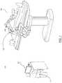
- FIG. 1illustrates an embodiment of a master/slave surgical tool system for minimally invasive surgery, the master device employing joysticks for manipulating the slave surgical tools.
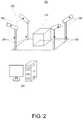
- FIG. 2illustrates an embodiment of a three-dimensional motion tracking system.
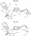
- FIG. 3Aillustrates an embodiment of master device movement within the free working space while the master/slave surgical system is in active mode.
- FIG. 3Billustrates an embodiment of slave device effector movement shown on a video display while the master/slave surgical system is in active mode.
- FIG. 3Cillustrates an embodiment of master device movement within the free working space while the master/slave surgical system is in camera mode.
- FIG. 3Dillustrates an embodiment of slave device camera movement changing the field of view on video display while the master/slave surgical system is in camera mode.
- FIG. 3Eillustrates an embodiment of master device movement within the free working space while the master/slave surgical system is in alignment mode.
- FIG. 3Fillustrates an embodiment of slave device effector inactivity on a video display while the master/slave surgical system is in alignment mode.
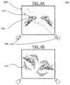
- FIG. 4Aillustrates representative effectors and emulators within a free working space, according to one embodiment.
- FIG. 4Billustrates a system for providing haptic feedback during alignment of a master/slave surgical system, according to one embodiment.
- FIG. 5Aillustrates the free working space of a master/slave surgical system operating in active mode without relative misalignment and with the emulators within the limited working area, according to one embodiment.
- FIG. 5Billustrates the video display during active mode operation when the effectors remain within the limited working area, according to one embodiment.
- FIG. 5Cillustrates a situation within the free working space of a master/slave surgical system triggering alignment mode operation due to motion of the emulators near the boundaries of the representative limited working area causing relative misalignment, according to one embodiment.
- FIG. 5Dillustrates the video display during alignment mode operation when the effectors are at the boundaries of the limited working area, according to one embodiment.
- FIG. 5Eillustrates a situation within the free working space of a master/slave surgical system reentering active mode operation due to realignment of the position of the emulators and the position of the representative effectors, according to one embodiment.
- FIG. 5Fillustrates the video display during active mode operation due to realignment of the position of the emulators and the position of the representative effectors, according to one embodiment.
- FIG. 6illustrates an emulator designed for grip detection, according to one embodiment.
- FIG. 7Aillustrates translational movement of the emulators within the free working space for control of the surgical effectors at the surgical site while the master/slave surgical system is operating in active mode, according to one embodiment.
- FIG. 7Billustrates translational movement of the effectors resulting from translational movement of the emulators displayed on the video screen while the master/slave surgical system is operating in active mode, according to one embodiment.
- FIG. 7Cillustrates translational movement of the emulators within the free working space for control of the camera at the surgical site while the master/slave surgical system is operating in camera mode, according to one embodiment.
- FIG. 7Dillustrates translational movement of the camera resulting from translational movement of the emulators displayed on the video screen while the master/slave surgical system is operating in camera mode, according to one embodiment.
- FIG. 7Eillustrates rotational movement of the emulators within the free working space for control of the effectors at the surgical site while the master/slave surgical system is operating in camera mode, according to one embodiment.
- FIG. 7Fillustrates rotational movement of the effectors resulting from rotational movement of the emulators displayed on the video screen while the master/slave surgical system is operating in camera mode, according to one embodiment.
- FIG. 8Ais an illustration of the emulators and the representative effectors during the first iteration of the ratcheting process, according to one embodiment.
- FIG. 8Bis an illustration of the effectors during the first iteration of the ratcheting process, according to one embodiment.
- FIG. 8Cis an illustration of the emulators and the representative effectors during the second iteration of the ratcheting process, according to one embodiment.
- FIG. 8Dis an illustration of the effectors during the second iteration of the ratcheting process, according to one embodiment.
- FIG. 8Eis an illustration of the emulators and the representative effectors during the third iteration of the ratcheting process, according to one embodiment.
- FIG. 8Fis an illustration of the effectors during the third iteration of the ratcheting process, according to one embodiment.
- FIG. 9illustrates a motion tracking system that self-monitors calibration, according to one embodiment.
- FIG. 10Aillustrates a wearable surgical viewing system that translates a large magnification distance to large surgical effector movements, according to one embodiment.
- FIG. 10Billustrates a wearable surgical viewing system that translates a small magnification distance to small surgical effector movements, according to one embodiment.
- FIG. 11Aillustrates a surgical viewing system with a changeable magnification setting that translates small magnifications to large surgical effector movements, according to one embodiment.
- FIG. 11Billustrates a surgical viewing system with a changeable magnification setting that translates large magnifications to small surgical effector movements, according to one embodiment.
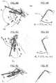
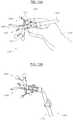
- FIGS. 12A-12Fillustrate an emulator and a representative medical device during a clutched roll process, according to one embodiment.
- FIGS. 13A-13Billustrate an emulator, according to another embodiment.
- FIG. 14illustrates an emulator, according to yet another embodiment.
- FIG. 15illustrates an emulator, according to still another embodiment.
- This descriptionpresents a method for robotically controlling medical devices (e.g., surgical effectors, tools, devices, or instruments) at a target site (e.g., a surgical site) that utilizes the highly specialized manual skills and techniques developed by surgeons over time.
- a motion tracking systemthat directly translates the motion of hand(s) of an operator (e.g., a surgeon) in free space to motions of a robotic surgical effector at the surgical site.
- the system tracking, interpreting, and translating the position and actions of the surgeoncreates a more characteristic experience for the operator.
- the presented robotic surgical systemyields a more natural transition towards advanced robotic techniques for surgical operations from the widely used manual techniques.
- the systemincludes an emulator held by the operator and operated in a free working space (FWS), the emulator representing a corresponding medical device at the target site.
- the emulator designclosely mimics the corresponding medical device at the target site in weight, range of motion, and functional abilities, e.g. the surgeon holding surgical scissor emulators is controlling surgical scissors at the target site.
- the systemmay comprise at least one detector configured to track the emulator within the FWS and/or at least one detector (e.g., imaging device) configured to track the medical device at the target site.
- the detectormay comprise one or more components of electromechanical systems such as, for example, encoders, potentiometers, linear variable differential transformers (LVDT), and rotary variable differential transformers (RVDT).
- FIG. 1is an illustration of a conventional master/slave robotic surgical system 100 , used to perform surgical operations.
- the systemcomprises a slave device 102 and a master device 104 .
- the slave devicecomprises a surgical effector 106 that performs surgical procedures at a surgical site 108 .
- the movements of the surgical effectorsare a reproduction of movement representative of the surgical procedure performed by the operator 110 at the master device.
- the master/slave surgical systemoperates in one of three modes: active, alignment, or camera. Active mode engages during standard surgical procedures, alignment mode during alignment of the master and slave devices, and camera mode for the manipulation of the camera near the surgical site.
- Master/slave surgical systemsinclude one or more robotic surgical tools configured to be manipulated by encoded signals.
- the encoded signalswill typically be electronic signals sent via wire or wirelessly from a remote location, where the operator is controlling the master device, to the location where the surgical effectors are being robotically manipulated by the slave device.
- the master deviceincludes one or more surgical tool emulators which correspond to at least some of the surgical effectors being controlled by the slave device at the surgical site. Oftentimes these emulators are mounted to and supported by the master device as a set of joysticks or similar.
- the master devicecomprises a motion tracking system to track and interpret the motion of the emulators and computational system for translation of master device movements to slave device surgical effectors at the surgical site.
- FIG. 2demonstrates a three-dimensional motion tracking system 200 including a motion tracking apparatus 202 and a computational system 204 .
- the motion tracking apparatusis in the form of an open space surrounded by a system of detectors 206 mounted on supportive stanchions 208 .
- the system of detectorsis capable of tracking the position and motion of objects within a FWS 210 .
- the system of detectorsis coupled to the computational system such that encoded signals from the detectors can be received and interpreted by the computational system which may generate a set of motion instructions for the slave device.
- the motion tracking apparatusmay be constructed as a controlled environment with the system of detectors at predefined locations within the environment and the FWS being confined within the controlled environment.
- the controlled environmentmay be configured as a box with the one face removed, as a box with three adjacent faces and the other faces removed, as a box with two opposing faces and the other faces removed, a platform, or the like.
- the system of detectorsmay include a set of video cameras mounted to stanchions surrounding the FWS.
- the camerasare electronically coupled to a computational system capable of simultaneously inputting multiple video sources, recognizing independent objects within the FWS, calculating orientation metrics of objects within the FWS, interpolating multiple two-dimensional sets of orientation metrics into three dimensions, calculating the relative orientation metrics between objects within the FWS, and translating the orientation metrics as a set of motion instructions for the surgical tool.
- the orientation metricsare independently monitored for each object within the FWS (further elaborated below) and may include position, pitch, yaw, roll, speed, acceleration, distance, and similar.
- the system of detectorsmay include any method capable of determining the orientation metrics of objects within the FWS including infrared sensors, acoustic sensors, and similar.
- the FWSrepresents the area that objects and their orientation metrics are able to be accurately measured by the motion tracking apparatus.
- the position, size, and shape of the FWSmay be determined by the relative positions of the detectors making up the system of detectors. Additionally, the position, size, and shape of the FWS are limited by the computational system to prevent movement of the surgical tool outside a set of positional boundaries representing areas the surgical tool should not (e.g. vulnerable tissue) or cannot access (e.g. outside of slave motion constraints). Finally, the position size and shape of the FWS may be specifically constructed to represent the space being manipulated by the surgical system.
- the master/slave surgical systemoperates in one of three modes: active, alignment, or camera.
- Active modefor use during standard surgical procedures
- alignment modeduring alignment of the master and slave devices
- camera modefor the manipulation of the camera near the surgical site.
- FIGS. 3A-3Eillustrates these operative modes of the master slave surgical system 300 and how changes in the orientation metrics of the emulators within the FWS translates to movement of the effectors or camera at the surgical site in the various operative modes.
- FIG. 3Aillustrates a two-dimensional projection of the FWS 302 and the objects within.
- the user's hands 304 and the emulators 306hereafter in combination referred to as the emulators for clarity of description, within the FWS are monitored by the detector system configured to track their motion 308 (i.e., orientation metrics) as part of the master device in active mode.
- FIG. 3Billustrates a video display 310 showing the slave surgical effectors 312 at the surgical site.
- changes in the orientation metrics of the emulators within the FWSare translated into motion of the surgical effectors 316 at the surgical site which is shown on the video display.
- the video display componentmay be any number of devices capable of representing visual information such as a television screen, a computer screen, projected images on a surface, a personal media display device, a heads up display or the like.
- the visual displaymay be generated by a three-dimensional camera, a stereoscopically-arranged pair of cameras, or a three-dimensional representation of space created from a plurality of two-dimensional image sources, and similar.
- the corresponding visual displaymay be viewed in a method used to present three-dimensional video displays such as a stereoscopic device, goggles with augmented reality, a virtual reality system, a holographic display system and similar.
- FIG. 3Cillustrates a similar system as FIG. 3A for tracking the emulators within a FWS using a detector system configured to track their motion 320 as part of the master device in camera mode.
- FIG. 3Dillustrates a video display showing the slave surgical effectors at the surgical site while the master/slave system is operating in camera mode 330 . While in camera mode, changes in the orientation metrics of the emulators within the FWS are translated into motion of the camera at the surgical site. Motion of the camera at the surgical site moves the field of view 332 shown on the video display.
- FIG. 3Eillustrates a similar system as FIG. 3A for tracking emulators within a FWS using a detector system configured to track their motion 340 as part of the master device in alignment mode.
- FIG. 3Fillustrates a video display showing the slave surgical effectors at the surgical site while the master/slave system is operating in alignment mode 350 . While in alignment mode, motion of the effectors and the camera at the surgical site are terminated, i.e. changes in the orientation metrics of the emulators within the FWS are not translated into motion of the camera or the effectors at the surgical site.
- the master/slave surgical systemit may be necessary for the operator to change between operative modes. These changes may be accomplished via a command to the master device.
- the commandmay include a keyboard input, a mouse button click, a vocal command or similar.
- the master systemmay be calibrated to automatically shift between operative modes in specific circumstances or situations that may be present at the slave device or the master device. Several of these systems are discussed below.
- FIGS. 3A, 3C, and 3Eare representative of a video input received by the computational system from the detector system and do not necessarily illustrate a video display showing the emulators within the FWS, however some systems may include such a display.
- FIGS. 4B-4C and the discussion belowillustrate a system for introducing haptic feedback to assist the operator in the alignment of a master/slave surgical system 400 .
- FIG. 4Aillustrates a two-dimensional projection of the emulators within the FWS which are monitored by the detector system configured to track their motion as part of the master device.
- the computational systemconcurrently monitors orientation metrics of the slave surgical effectors at the surgical site and the orientation metrics of the emulators within the FWS. Additionally, the computational system creates and monitors a set of orientation metrics within the FWS representing the orientation metrics of the slave surgical effectors at the surgical site, hereafter the representative effectors. Note that the representative effectors exist only within the computational system and are only illustrated in the Figures for ease of understanding.
- a positione.g. the position of the emulators 402
- movemente.g. move (or movement of) the surgical effectors
- differences in the orientation metrics between separate objects monitored by the computational systemare referred to as a relative misalignment, e.g. the relative misalignment between the representative effectors and the emulators.
- the usermay move the position of the emulators towards the position of the representative effectors in the FWS.
- the emulatorgives a haptic feedback response 406 .
- the feedback responsemay be in the form of a pulse, vibration, click, temperature change, texture change, size change, or similar.
- the haptic feedback responsemay originate from a component associated with the surgical tool system that is not the emulator, such as an armrest, a wrist strap, eyewear, supportive surfaces, gloves, or similar.
- haptic feedbackmay represent different aspects of the surgical procedure, such as relative misalignment of the emulators and the surgical effectors, mishandling of the emulators, elapsing time, patient condition, and similar.
- the slave devicemay have a limited range of motion due to the type of surgery, condition of the patient, nearby tissues types or various other limiting factors.
- the user of the master devicemay move the emulators in the FWS to a position outside the range of motion of the surgical effectors and may create conditions that may result in a misalignment between the emulators and the effectors.
- the embodiments described hereafterallow for the alignment of the master/slave system after a relative misalignment between the representative effectors and the emulators near the limits of surgical effector movement 500 .
- FIG. 5Aillustrates a two-dimensional projection of the position of the emulators and the position of the representative effectors within the FWS.
- the emulatorsare monitored by a detector system configured to track their motion as part of the master device.
- the position of the emulators, the position of the representative effectors, and the relative misalignment between the twoare all monitored by the computational system.
- the surgical effectorsmay have a limited range of motion and operate in a limited working area (LWA) 510 .
- the computational systemmonitors the boundaries of the LWA and creates and monitors a corresponding set of representative boundaries within the FWS 502 , hereafter the representative LWA 502 .
- FIG. 5Billustrates a video display showing the surgical effectors at the surgical site during active mode operation.
- the surgical effectorsoperate within boundaries of the LWA 510 and motion outside of those boundaries is not allowed.
- the LWAis monitored by the computational system which also creates and monitors the representative LWA 502 within the FWS as shown in FIG. 5A . While there is no relative misalignment between the emulators and the representative effectors and the surgical effectors remain within the LWA the master/slave surgical system operates in active mode.
- FIG. 5Cillustrates an instance in which the position of the emulators moves 520 outside the boundaries of the representative LWA 502 .
- the surgical effectorsreach the boundaries of LWA at the surgical site (they are now at the limit of their range of motion) and cease movement causing the position of the representative effectors to persist at the boundaries of the representative LWA 522 .
- the master/slave surgical systemmay automatically enter alignment mode.
- FIG. 5Dillustrates the video display in the instance where the position of the emulators moves outside the boundaries of the representative LWA 502 .
- the position of the surgical effectors at the surgical sitereach the limit to their range of motion and the boundaries of the LWA 530 causing the surgical effectors cease movement.
- the userWhile in alignment mode, the user works to reestablish alignment of the master/slave surgical system. As shown in FIG. 5E , the user may move the position of the emulators 540 towards the position of the representative effectors in the FWS. The position of the representative effectors has persisted at the boundary of the representative LWA 542 because motion of the surgical effectors at the surgical site has been disallowed. When the position of the emulators matches the position of the representative effectors within the FWS and the relative misalignment between the two 544 drop below a threshold defined in the computational system, the master/slave surgical system may automatically reenter active mode.
- the position of the emulators and the position of the representative effectorsare in close proximity to boundaries of the representative LWA. Small, subsequent motions of the emulators may quickly result in relative misalignments between the representative effectors and the emulators that result in automatically reentering alignment mode.
- the computational systemmay create a new adjusted representative LWA 546 which replaces the original representative LWA.
- the adjusted representative LWAstill corresponds to the boundaries of the LWA at the surgical site; however, the boundaries of the adjusted representative LWA have been moved within the FWS by the computational system to allow more movement by the emulators before reaching the boundaries of the adjusted representative LWA and creating misalignment that would create a need to re-enter into alignment mode.
- FIG. 5Fillustrates the video display in the case where the position of the emulators and the position of the representative effectors match and there is no longer relative misalignment.
- the position of the surgical effectorsremains at the boundaries of the LWA 550 as the motion of the effectors ceased when the master/slave surgical system automatically entered alignment mode. Now that the relative misalignment has been corrected the tool may reenter active mode and movement of the surgical effectors again reflects motion of the emulators in the FWS, assuming the emulator's motion remains within the adjusted representative LWA 546 .
- the realignment system outlined in the above discussion of FIGS. 5A-5F for a master/slave surgical system utilizing gesture tracking technologyrepresents an exemplary embodiment. However, there are several other embodiments to handle potential relative misalignment between the emulators and the representative effectors when the surgical effectors are operating near the boundaries of the LWA.
- the computational systemmay have a secondary spatial or temporal tolerances associated with the relative misalignment threshold that triggers entering alignment mode.
- the spatial toleranceallows slight movements above the relative misalignment threshold before entering alignment mode.
- the temporal toleranceallows movements with relative misalignment above the threshold for a small period of time before entering alignment mode. If the relative misalignment between the emulators and the representative effectors does not decrease below the threshold before the temporal or spatial tolerances are surpassed, the system will automatically enter alignment mode. If the relative misalignment decreases below the threshold before the tolerances are surpassed, the system will remain in active mode.
- the LWA(and the corresponding representative LWA) is a three-dimensional space with a set of boundaries in which the surgical effectors are able to move and operate.
- the boundaries of the LWArepresent areas that should not be accessed by the surgical effectors (e.g. vulnerable tissues) and motion of the emulators that would cause movement of the effectors into these areas should trigger cessation of effector movement.
- the motion tracking systemmay instead translate the movement of the emulators outside the representative LWA into movement of the surgical effectors representing some projection of the movement onto the boundary of the LWA. This would be demonstrated on the video display as the surgical effectors sliding along the range of their motion limits without entering alignment mode.
- the surgical effectorscease movement at the boundaries of the LWA at the surgical site.
- the emulatorsmay reenter the boundaries of the representative LWA at a different non-critical position from where they exited the representative LWA.
- the surgical effectorsmay automatically move to a position within the boundaries of the LWA computed from the new position of the emulators in the representative LWA.
- the position of the representative effectorsis automatically set to the current position of the emulators after the movement of the surgical effectors. This would be demonstrated on the video display as the surgical effectors ceasing movement at one point at the boundary of the LWA and subsequently moving to a new position within the LWA after some time without entering alignment mode.
- Any process that functions to realign the master/slave surgical systemmay allow for the computation and creation of an adjusted representative LWA similar to the system illustrated in FIG. 5E .
- the master/slave surgical systemrelies on the operator to control emulators on the master device that represent and control surgical effectors on the slave device
- FIG. 6shows a surgical emulator designed to identify unintended emulator movements 600 .
- the surgical emulatorcan be held in the operator's hand and is designed to be a representation of the surgical effector at the surgical site.
- the emulatorhas at least one or more touch activated sensors 602 and/or light emitting/reflecting surfaces 604 .
- the emulatormay be wirelessly coupled or connected via umbilical to the master device.
- the master device and the emulatormay both produce and receive signals for controlling the state of any sensor, light emitting surface, or light reflective surface that may make up the emulator.
- the touch activated sensorsmay be any component or set of components used to detect the grip of the operator, such as capacitive pads, force-sensitive resistors, switches, pressure-activated switches, infrared detector and emitter pairs, or similar.
- the light emitting or reflective surfacesmay be any component or set of components that would be occluded by the normal grip of the operator such as, light emitting diodes, fluorescent materials, lasers, reflective tape, metallic surfaces, or similar.
- the master deviceis wirelessly coupled to the emulator which consisting of capacitive pads in an orientation such that the operator's normal grip on the emulator will create and transmit an encoded signal to the master device indicating that the emulator is being held in the operator's hand in an operative manner.
- the emulatorwill create and transmit an encoded signal to the master device indicating the emulator is not being held in an operative manner.
- the master devicemay disengage active mode, cease the movement of the surgical effectors at the surgical site, and enter alignment mode until normal handling of the emulator is restored.
- the emulatorutilizes light emitting diodes in an orientation such that the operator's normal grip on the emulator occludes the light from being emitted.
- the motion tracking systemis further configured to detect the appearance of the light emitted by the light emitting diodes when the operator's normal grip is compromised.
- the master devicemay disengage active mode, cease the movement of the surgical effectors at the surgical site, and enter alignment mode until normal handling of the emulator is restored.
- the emulatormay not be specifically designed to signify changes in the users grip.
- the detector system and the computational systemmay be further configured to recognize the operator's normal and abnormal grip on the emulator via object, gesture, or motion recognition algorithms.
- the orientation of the medical devicesmay make viewing specific areas difficult when the medical devices are in the desired line of sight of the camera monitoring a specific area at the target site (e.g., a surgical site).
- the ability to manipulate the position of camera at the surgical site and the corresponding field of view on the video display using the emulatorsis advantageous, providing a more streamlined surgical operation.
- FIGS. 7A-7Fdepict a camera control system for a master/slave surgical system 700 .
- the system 700comprises emulator(s) (e.g., the emulators 402 ) configured to be held and operated in a FWS (e.g., the FWS 302 ), the emulator(s) representing medical device(s) (e.g. surgical effectors) at the target site.
- the system 700may comprise one or more detectors (e.g., the detectors 206 or imaging device(s)) may be configured to track the emulator(s) within the FWS.
- the system 700may comprise: at least one computer-readable memory having stored thereon executable instructions; and at least one processor in communication with the at least one computer-readable memory and configured to execute the instructions to cause the system 700 to perform steps as described below.
- the motion tracking systeminterprets translational movement of the emulators to be translational movement of the camera position. Consequently, in camera mode translational movement of the emulator does not correspond/result in translational movement of the surgical effectors. However, in camera mode rotational motion of the emulators does result in rotational motion of the surgical effectors. Consequently, in camera mode rotational movement of the emulator does not result in rotational motion of the camera.
- FIG. 7Aillustrates a two-dimensional projection of the position of the emulators and the position of the representative effectors within the FWS. While in active mode, the translational movement 702 of the emulators is monitored by a detector system configured to track the emulator motion as part of the master device.
- FIG. 7Billustrates a video display 310 showing the surgical effectors at the surgical site during active mode operation.
- the movement of the emulatorsis translated into motion of the surgical effectors at the surgical site 710 . While in active mode, translational movement 712 and rotational movement 714 of the camera are not allowed.
- the operatormay engage camera mode to change the position of the camera and the corresponding field of view on the video display.
- camera modetranslational movement of the emulators 720 within the FWS is monitored by the detector system.
- FIG. 7Dillustrates that in camera mode, translational movement of the camera is allowed and a translational movement of the emulators does not generate movement for the surgical effectors 730 , but instead generates translational movement of the camera 732 altering the field of view on the video display.
- FIG. 7Eillustrates that in camera mode a rotational movement of the emulators generates movement for the surgical effectors limited to rotational motions 750 . Rotational movement of the camera is disallowed in camera mode.
- FIGS. 7A, 7C, and 7Eare representative of a video input received by the computational system from the detector system and do not illustrate a video display showing the emulators within the FWS.
- the at least one processormay be configured to execute the instructions to cause the system to: receive a signal from at least one detector indicative of a translational movement of the emulator within the FWS; and generate instructions, based on the translational movement of the emulator, to move an imaging device within a plane defined by pitch and yaw axes of the imaging device.
- translational movement of the emulatordoes not result in a translational movement of the medical device.
- the at least one processormay be further configured to execute the instructions to cause the system to receive a signal from the at least one detector indicative of a rotational movement of the emulator within the FWS; and generate instructions, based on the rotational movement of the emulator, to rotate the medical device along a roll axis of the medical device.
- rotational movement of the emulatordoes not result in a rotational movement of the imaging device.
- the relative alignment offseti.e., misalignment
- the representative medical devicese.g., surgical effectors, tools, devices, or instruments
- the slight misalignmentis allowed to reduce the total time it takes for the user to achieve adequate alignment.
- a systemmay comprise: an emulator configured to be held and operated in a FWS, the emulator representing a medical device at a target site; at least one detector configured to track the emulator within the FWS; at least one computer-readable memory having stored thereon executable instructions; and at least one processor in communication with the at least one computer-readable memory and configured to execute the instructions to cause the system to perform the method as described below.
- FIGS. 8A-8Fdepict a representation of a method to automatically reduce the relative misalignment between the emulators and the representative effectors within the FWS 800 using what is herein referred to as “ratcheting” technique, which is described in the following paragraphs.
- FIG. 8Adepicts a linear representation of the position of the emulators 802 and a linear representation of the position of the representative effectors 804 . Additionally, FIG. 8B depicts a linear representation of the position of the surgical effectors 810 .
- ⁇ nis the relative misalignment between the position of the emulators and the position of the representative surgical effectors.
- ⁇ nis a movement of the emulators the generates a corresponding movement of the effectors ⁇ n , where the two will generally differ from each other with respect to position orientation metrics but not rotation orientation metrics.
- ⁇ nis an additional movement of the emulators to create a total movement ⁇ n that reduces the relative misalignment ⁇ n .
- the surgical systemis operating in active mode with a relative misalignment ⁇ 1 between the emulators and the representative effectors.
- the operatormoves the emulators by ⁇ 1 to create a corresponding movement of the slave surgical effectors ⁇ 1 at the target site, such as, for example, the surgical site.
- a relative misalignment ⁇ 1between the emulators and the representative effectors.
- the operatormoves the emulators by ⁇ 1 to create a corresponding movement of the slave surgical effectors ⁇ 1 at the target site, such as, for example, the surgical site.
- an operator movement of ⁇ 1creates a direct translation of motion to the surgical effectors ⁇ 1 .
- the movement of the emulators by ⁇ 1yields a lesser relative misalignment between the emulators and the representative effectors.
- FIGS. 8C and 8Dwherein the same process occurs with ⁇ 2 being the lesser relative misalignment between the emulators and the representative effectors resulting from the total movement ⁇ 1 .
- the computational systemcomputes an additional (or lesser) amount of movement ⁇ 2 as a function of ⁇ 2 , ⁇ 2 , ⁇ 2 that when added to (or subtracted from) ⁇ 2 represents the total actual movement of the emulators ⁇ 1 .
- the movement of the emulators by ⁇ 2yields an even smaller in magnitude relative misalignment between the emulators and the representative effectors.
- This processcontinually iterates as in FIGS. 8E and 8F until the relative misalignment ⁇ n is neutralized.
- the at least processormay be configured to execute the instructions to cause the system to: determine an alignment offset between a location of the emulator and a location of the medical device; during a medical procedure, determine a first movement amount based on a signal from the at least one detector indicative of a first movement of the emulator within the FWS; adjust the first movement amount by a first adjustment value; and generate instructions to move the medical device based on the adjusted first movement amount, wherein movement of the medical device by the adjusted first movement amount reduces the alignment offset between the location of the emulator and the location of the medical device.
- the at least one processormay be further configured to execute the instructions to cause the system to repeat the steps described above to further reduce the alignment offset.
- the at least one processormay be further configured to execute the instructions to cause the system to: during the medical procedure, determine a second movement amount based on a signal from the at least one detector indicative of a second movement of the emulator within the FWS; adjust the second movement amount by a second adjustment value; and generate instructions to move the medical device based on the adjusted second movement amount, wherein movement of the medical device by the adjusted second movement amount reduces the alignment offset between the location of the emulator and the location of the medical device.
- the movement of the medical device by the adjusted first and second movement amountsmay eliminate the alignment offset between the location of the emulator and the location of the medical device.
- the alignment offset between the location of the emulator and the location of the medical devicemay be eliminated after more than two adjustments or movements of the medical device.
- the master/slave surgical system controlled via an optical motion tracking systemrequires calibration with one or more known objects in a known geometry before it can provide accurate tracking data.
- the calibrationcan be affected by many factors, such as lighting and temperature, and may change or degrade over time. It is desirable to maintain optimal calibration with minimal intervention from the user to create accurate translations of motion from the master device to the slave device in an efficient manner.
- FIG. 9represents a motion tracking system that self-monitors the quality of the calibration 900 .
- the position of the emulators within the FWSare monitored by the detector system configured to track their motion, depicted by a two-dimensional projection of the FWS and the objects within.
- the configuration of the detector systemutilizes one or more known objects in a known orientation 902 in the field of view of the detector system.
- the known objectsmay be a set of light sources or reflective surfaces that can be monitored by the detector system.
- the light sourcesmay be light emitting diodes, infrared emitters, lasers, or similar.
- the reflective surfacesmay be reflective tapes, metals, or similar.
- the known objectsmay also be a set of objects or surfaces.
- the operatorcalibrates the motion tracking system with an orientation baseline using the known objects while the tool is in alignment mode. Once the operator engages active mode, the computational system actively compares the position of objects within the FWS to the orientation baseline created during calibration.
- the toolmay indicate to the user that calibration has been compromised.
- the toolautomatically recalibrates the orientation baseline using the position of the known objects.
- the surgical systemhas a translation ratio that represents the proportion of the magnitude of motion (change in orientation metric) that is translated from the emulators to the effectors. Depending on this ratio, an operator may have to move the emulators a greater or lesser distance to cause a certain amount of motion in the effectors.
- a surgical systemhas only a fixed translation ratio, or a translation ratio that is not easily changeable during surgical procedures, it is difficult for the operator to rapidly change or move between magnifications or fields of view used on the video display.
- the master/slave surgical systemis capable of motion scaling.
- surgical effectors of the slave devicemay require much less movement than the operator's hands use in moving the emulators, allowing the operator to make comparatively larger motions to cause comparatively smaller/finer actions of the surgical effectors.
- FIG. 10represents a system that allow a high level of surgical control at various video display magnifications without requiring the surgeon to issue separate commands to adjust the translation ratio between the master device and slave device 1000 .
- the operator of the master deviceuses a video display comprising a wearable set of stereoscopic goggles 1002 that display an image of the surgical effectors at the surgical site.
- the gogglesconsist of a system that monitors and measures the distance between the goggle eyepieces and the emulators, hereafter the magnification distance 1004 .
- the movement of the emulators 1006is converted by the translation ratio 1008 into a movement of the surgical effectors 1010 based on the magnification distance.
- a change in a magnification distancefor example by the operator moving the googles closer to or further from the emulators, creates a corresponding change in the magnification distance, and therefore in the translation ratio.
- FIG. 10BA specific example of this is demonstrated in FIG. 10B .
- the translation ratiocreates a smaller movement 1014 in the surgical effectors for a similar movement of the emulators.
- the translation ratiocreates a larger movement of the surgical effectors for a similar movement of the emulators.
- the system that monitors and measures the magnification distancemay comprise any components or set of components that would allow for the measurement of the magnification distance such as stereoscopic cameras mounted on the goggles, light sources and detectors mounted on the goggles and emulators, a camera mounted on the goggles and calibration markers on the emulator, or similar.
- magnification distancemay be monitored by the same motion tracking system that monitors the position of the emulators, or by a motion tracking system configured to track the position of the operator's head or eyes relative to the emulators.
- FIG. 11represents another system which enables a high level of surgical control at various video display magnifications without forcing the surgeon to issue separate commands to adjust the translation ratio between the master device and slave device 1100 .
- the operator of the master deviceuses a video display 1102 with a scalable magnification setting that displays the surgical effectors at the surgical site.
- the video displayhas a specific magnification setting 1104 .
- a movement change of the emulators 1106is converted by the translation ratio 1108 into movement of the surgical effectors 1110 based on the specific magnification setting.
- FIG. 11BA specific example of this is demonstrated in FIG. 11B .
- the translation ratiocreates a smaller movement 1114 in the surgical effectors for a similar movement of the emulators.
- the translation ratiocreates a larger movement of the surgical effectors for a similar movement of the emulators.
- an operatore.g., a physician or surgeon
- an emulatorthat represents and controls a medical device (e.g., surgical effectors, tools, devices, or instruments).
- the systemmay be configured to control an instrument with extended roll capability, such as, for example, a medical device with an end-effector controlling or otherwise manipulating a curved needle.
- the ability to control the medical devicemay be limited by the roll capability of an operator's wrist.
- the operatormay not be able to rotate his/her wrist beyond certain angles—for example, about 66.1° for pronation (i.e., rotation of the wrist such that the palm is facing downward or backward/posteriorly) or about 75° for supination (i.e., rotation of the wrist such that the palm is facing upward or forward/anteriorly).
- the systemmay be desirable for the system to enable the operator to employ the extended roll capability of the medical device (e.g., extending the roll capability beyond that of the operator's wrist) and not be limited or hampered by the anatomical limitation of the operator (e.g., anatomical limitation of the operator's wrist). This can help the operator conduct tasks requiring extensive instrument roll, such as, for example, during suturing.
- One aspect of the disclosureprovides the operator with the ability to perform clutched roll of the medical device, allowing the operator to activate a clutch (e.g., a clutch foot pedal, button, or other input to activate the decoupling of the absolute roll angle of the medical device from that of the emulator) and thereby roll the medical device farther than his/her wrist could go.
- a clutche.g., a clutch foot pedal, button, or other input to activate the decoupling of the absolute roll angle of the medical device from that of the emulator
- This clutched roll featureallows the operator to use a ratcheting turning motion to roll the instrument in one motion, pause the roll, and then continue rolling the instrument in a subsequent motion, while, in some cases, maintaining wrist yaw-pitch.
- the clutched roll feature of the systemfacilitates decoupling an absolute roll angle of the medical device from an absolute roll angle of the emulator.
- the clutched roll of the medical deviceallows for decoupling the roll axis from the other axes of the medical device (i.e., the yaw axis or the pitch axis).
- rotational movements with respect to the roll axis of the emulatorare not translated into rotational movements with respect to the roll axis of the medical device, whereas the rotational movements of the emulator with respect to the other axes are translated to the medical device.
- FIGS. 12A-12Fillustrate a system 1200 configured to perform a clutched roll.
- the system 1200may comprise an emulator 1206 configured to be held and operated in a FWS (e.g., the FWS 302 ), the emulator representing a medical device 1214 at a target site; one or more detectors (e.g., detectors 206 ) configured to track the emulator 1206 within the FWS 302 ; one or more detectors configured to track the medical device 1214 ; at least one computer-readable memory having stored thereon executable instructions; and at least one processor in communication with the at least one computer-readable memory and configured to execute the instructions to cause the system to perform a clutched roll as described below.
- a FWSe.g., the FWS 302
- detectorse.g., detectors 206
- FIG. 12Aillustrates a two-dimensional projection of the position of the emulator 1206 and the position of the representative medical device 1214 within the FWS 302 .
- the movement of the emulator 1206e.g., clockwise rotation by 90 degrees
- a detector systemconfigured to track the motion of the emulator.
- FIG. 12Billustrates a video display 310 showing the medical device at the target site during the non-clutched mode operation.
- the rotational movement 1208 of the emulator 1206e.g., clockwise rotation by 90 degrees
- the system 1200may rotate the medical device 1214 based on the rotational movement of the emulator 1206 by, for example, conducting a spherical linear interpolation (slerp) of the current medical device quaternion towards the emulator quaternion.
- the operatormay rotate the emulator with his/her wrist with respect to its roll axis as far as the anatomical structure of the wrist allows.
- the operatormay activate a clutched roll mode of the system to decouple an absolute roll angle of the medical device 1214 from an absolute roll angle of the emulator 1206 .
- a rotational movement 1210 of the emulator 1206e.g., counterclockwise rotation by 90 degrees
- the operatormay rotate his/her wrist to its original position with respect to its roll axis without moving the medical device 1214 .
- steps to conduct the clutched rollare described below as follows.
- a cross product and a dot product of the z-vector of the emulator 1206e.g., a unit vector along the roll axis of the master device
- the z-vector of the medical device 1214e.g., a unit vector along the roll axis of the slave device
- the instantaneous rotation matrixis calculated using the following matrix formula:
- cpa cross product vector of the z-vector of the emulator 1206 and the z-vector of the medical device 1214 ;
- caa scalar of a cross product of the z-vector of the emulator 1206 and the z-vector of the medical device 1214 ;
- waa dot product of the z-vector of the emulator 1206 and the z-vector of the medical device 1214 .
- v icurrent orientation of the medical device 1214 ;
- v ftarget orientation of the medical device 1214 ;
- the medical device 1214is rotated based on the target orientation calculated above.
- the rotation of the medical device 1214may be conducted by a variety of techniques including, but not limited to slerp or linear interpolation (lerp).
- the operatorcan turn off the clutched roll mode and repeat rotating the emulator 1206 .
- the rotational movement 1212 of the emulator 1206e.g., clockwise rotation by 90 degrees
- the rotational motion 1220 of the medical device 1214 at the target sitee.g., clockwise rotation by 90 degrees.
- the operatormay repeat the first step and the second step until the desired rotation is achieved.
- FIGS. 12A, 12C, and 12Eare representative of a video input received by the computational system from the detector (e.g., detectors 206 ) and do not illustrate a video display showing the emulators within the FWS.
- the operator's handwould be holding the emulator 1206 .
- the operator's handis shown next to the emulator 1206 rather than over or covering the emulator 1206 .
- the surgical systemmay be monitored and/or controlled via a motion tracking system.
- the motion tracking systemmay be optical or electromagnetism (EM)-based.
- the clutched roll featuremay be used in a system that does not utilize the motion tracking system.
- features disclosed in other sectionsmay be used in a system that does not utilize motion tracking.
- the emulatormay be a mechanical emulator, and the detectors may be configured to track the mechanical movement of the mechanical emulator and/or the operation of the mechanical emulator by the operator.
- the systemmay comprise an emulator representing a medical device at a target site.
- the systemmay comprise a first set of one or more detectors configured to track the emulator.
- the systemmay comprise a second set of one or more detectors configured to track the medical device at the target site.
- the systemmay comprise at least one computer-readable memory having stored thereon executable instructions; and at least one processor in communication with the at least one computer-readable memory and configured to execute the instructions to cause the system to: receive, from the first set of one or more detectors, first data indicative of at least an orientation of the emulator, the first data comprising roll data, pitch data, and yaw data of the emulator; generate, based on a clutched user input, instructions to move the medical device based on the first data discounting the roll data of the emulator; and cause the medical device to move based on the instructions.
- the emulatormay be configured to be held and operated in a FWS; and the first set of one or more detectors may be configured to track motion of the emulator in the FWS.
- the emulatormay comprise a mechanical emulator; and the first set of one or more detectors may be configured to track mechanical movement of the emulator.
- the discounting of the roll data of the emulatormay be based on decoupling a roll axis of the emulator from yaw and pitch axes of the emulator. In one embodiment, the discounting of the roll data of the emulator may be based on decoupling an absolute roll angle of the medical device from an absolute roll angle of the emulator. In one aspect, the movement of the medical device based on the instructions may facilitate adjustment of a roll axis of the emulator with respect to a roll axis of the medical device.
- the at least one processormay be configured to execute the instructions to cause the system to receive, from the second set of one or more detectors, second data indicative of an orientation of the medical device at the target site, the second data comprising roll data, pitch data, and yaw data of the medical device; and the alignment of the respective roll axes of the emulator and the medical device is based on the pitch and yaw data of the emulator and the pitch and yaw data of the medical device.
- the at least one processormay be configured to execute the instructions to cause the system to: receive, from the first set of one or more detectors, third data indicative of a translational movement of the emulator; receive, from the second set of one or more detectors, fourth data indicative of a position of the medical device at the target site; and generate instructions to move the medical device based on the third and fourth data.
- the emulatormay be axially symmetric or axially asymmetric.
- FIGS. 13A and 13Billustrate an exemplary emulator 1300 that is axially symmetric.
- the emulator 1300comprises a handle 1302 , a connector 1304 , and arms 1306 and 1308 .
- the operatormay hold the emulator 1300 by either the handle 1302 or the connector 1304 (as shown by the hand 1310 of the operator).
- Each of the arms 1306 and 1308may comprise one or more branches 1307 and 1309 , respectively.
- the branches of the armmay be positioned symmetrically with respect to the longitudinal axis of the arm (e.g., branches 1309 of the arm 1308 ) or asymmetrically with respect to the longitudinal axis of the arm (e.g., branches 1307 of the arm 1306 ).
- the branches 1307 and 1309 of each arm 1306 or 1308may be positioned to be on the same plane.
- the plane formed by the branches 1307 and the plane formed by the branches 1309may, for example, be perpendicular to each other.
- the connector 1304may comprise a plurality of legs.
- the longitudinal length of the connector 1304may be modified by adjusting the bending degree of bending of legs of the connector 1304 .
- the connector 1304 and the handle 1302may be connected by a joint such that the connecting angle between the connector 1304 and the handle 1302 may be adjusted based on different grip positions of the operator.
- the axially symmetric emulator 1300may be beneficial because it can avoid an implication of mapping an operator grip roll angle (e.g., roll angle of the emulator 1300 ) to the instrument grip roll angle (e.g., roll angle of the medical device).
- the emulatormay be symmetric with respect to one or more of the pitch, yaw, and roll axes.
- FIG. 14illustrates an exemplary emulator 1400 that is axially asymmetric.
- the emulator 1400comprises a handle 1402 and arms 1406 and 1408 .
- Each of the arms 1406 and 1408may comprise one or more branches 1407 and 1409 , respectively.
- the handle 1402 of the emulatoris shaped to be axially asymmetric.
- an angular offset experienced by the operator(which is common in traditional manual medical devices that allow the device shaft to be rotated with respect to the handle) may be compensated for.
- FIG. 15illustrates an exemplary emulator 1500 that is axially asymmetric.
- the emulator 1500comprises one or more rings 1502 , one or more pinchers 1504 , a rod 1506 , and a support 1508 .
- the one or more rings 1502are configured to receive fingers of the operator (as shown by the hand 1510 of the operator).
- Each of the rings 1502is connected to one of the pinchers 1504 and enables the operator to manipulate the pinchers 1504 when the operator inserts his/her fingers into the rings 1502 .
- One or more pinchers 1504are connected to the rod 1506 , and the rod 1506 is mounted on the support 1508 .
- Tips of the pinchers 1504may be pushed toward the longitudinal axis of the rod 1506 , and the movement of the pinchers 1504 may be tracked by one or more detectors (e.g., sensors inside the rod 1506 ).
- the emulatormay be asymmetric with respect to one or more of the pitch, yaw, and roll axes.
- the emulator 1500may be used in conjunction with one or more medical devices that are configured to pinch or clamp or operate by a pinching movement of the operator, including but not limited to forceps, clamps, scissors, and vessel sealers.
- a pinching movement of the operatorincluding but not limited to forceps, clamps, scissors, and vessel sealers.
- the movement of the pinchers 1504may be detected by the sensors, and the medical device may be operated or moved based on the movement of the pinchers 1504 .
- Implementations disclosed hereinprovide systems, methods and apparatus for to robotically controlling a medical device. More specifically, implementations of the present disclosure relate to a system for reducing an alignment offset; a camera control system; and a system for a clutched roll.
- Couplemay indicate either an indirect connection or a direct connection.
- first componentmay be either indirectly connected to the second component via another component or directly connected to the second component.
- the methods described hereinmay be stored as one or more instructions on a processor-readable or computer-readable medium.
- computer-readable mediumrefers to any available medium that can be accessed by a computer or processor.
- a mediummay comprise random-access memory (RAM), read-only memory (ROM), electrically erasable programmable read-only memory (EEPROM), flash memory, compact disc read-only memory (CD-ROM) or other optical disk storage, magnetic disk storage or other magnetic storage devices, or any other medium that can be used to store desired program code in the form of instructions or data structures and that can be accessed by a computer.
- a computer-readable mediummay be tangible and non-transitory.
- codemay refer to software, instructions, code or data that is/are executable by a computing device or processor.
- the methods disclosed hereincomprise one or more steps or actions for achieving the described method.
- the method steps and/or actionsmay be interchanged with one another without departing from the scope of the claims.
- the order and/or use of specific steps and/or actionsmay be modified without departing from the scope of the claims.
- the term “plurality”denotes two or more. For example, a plurality of components indicates two or more components.
- the term “determining”encompasses a wide variety of actions and, therefore, “determining” can include calculating, computing, processing, deriving, investigating, looking up (e.g., looking up in a table, a database or another data structure), ascertaining and the like. Also, “determining” can include receiving (e.g., receiving information), accessing (e.g., accessing data in a memory) and the like. Also, “determining” can include resolving, selecting, choosing, establishing and the like.
Landscapes
- Engineering & Computer Science (AREA)
- Health & Medical Sciences (AREA)
- Life Sciences & Earth Sciences (AREA)
- Surgery (AREA)
- Physics & Mathematics (AREA)
- General Physics & Mathematics (AREA)
- Theoretical Computer Science (AREA)
- Medical Informatics (AREA)
- General Health & Medical Sciences (AREA)
- Business, Economics & Management (AREA)
- Educational Technology (AREA)
- Educational Administration (AREA)
- Public Health (AREA)
- Heart & Thoracic Surgery (AREA)
- Biomedical Technology (AREA)
- Molecular Biology (AREA)
- Animal Behavior & Ethology (AREA)
- Nuclear Medicine, Radiotherapy & Molecular Imaging (AREA)
- Veterinary Medicine (AREA)
- Robotics (AREA)
- Medicinal Chemistry (AREA)
- Chemical & Material Sciences (AREA)
- Algebra (AREA)
- Computational Mathematics (AREA)
- Mathematical Analysis (AREA)
- Mathematical Optimization (AREA)
- Mathematical Physics (AREA)
- Pure & Applied Mathematics (AREA)
- Oral & Maxillofacial Surgery (AREA)
- Pathology (AREA)
- Manipulator (AREA)
Abstract
Description
- Section I: Describes an overview of a conventional master/slave robotic surgical process.
- Section II: Describes an example of a three-dimensional motion tracking system for controlling slave surgical effectors at the surgery site.
- Section III: Describes the operative modes of a master/slave surgical system.
- Section IV: Describes a haptic response to indicate master/slave alignment.
- Section V: Describes a system for handling motion of the master device that would create motion of the slave device outside of its possible range of motion.
- Section VI: Describes an emulator for detecting the operator's grip on the emulators.
- Section VII: Describes a system for controlling a slave side camera with the emulators.
- Section VIII: Describes a method for the automatic elimination of master-slave alignment offsets.
- Section IX: Describes a motion tracking system that self-monitors the quality of its calibration.
- Section X: Describes a system that adjusts the master/slave motion ratio based on the view of the operator.
- Section XI: Describes a system for clutched roll.
I. Master/Slave Surgical System
vf=R×vi
Claims (20)
Priority Applications (2)
| Application Number | Priority Date | Filing Date | Title |
|---|---|---|---|
| US15/657,051US11037464B2 (en) | 2016-07-21 | 2017-07-21 | System with emulator movement tracking for controlling medical devices |
| US17/346,113US11676511B2 (en) | 2016-07-21 | 2021-06-11 | System with emulator movement tracking for controlling medical devices |
Applications Claiming Priority (2)
| Application Number | Priority Date | Filing Date | Title |
|---|---|---|---|
| US201662365308P | 2016-07-21 | 2016-07-21 | |
| US15/657,051US11037464B2 (en) | 2016-07-21 | 2017-07-21 | System with emulator movement tracking for controlling medical devices |
Related Child Applications (1)
| Application Number | Title | Priority Date | Filing Date |
|---|---|---|---|
| US17/346,113ContinuationUS11676511B2 (en) | 2016-07-21 | 2021-06-11 | System with emulator movement tracking for controlling medical devices |
Publications (2)
| Publication Number | Publication Date |
|---|---|
| US20180025666A1 US20180025666A1 (en) | 2018-01-25 |
| US11037464B2true US11037464B2 (en) | 2021-06-15 |
Family
ID=60988813
Family Applications (2)
| Application Number | Title | Priority Date | Filing Date |
|---|---|---|---|
| US15/657,051Active2038-07-01US11037464B2 (en) | 2016-07-21 | 2017-07-21 | System with emulator movement tracking for controlling medical devices |
| US17/346,113ActiveUS11676511B2 (en) | 2016-07-21 | 2021-06-11 | System with emulator movement tracking for controlling medical devices |
Family Applications After (1)
| Application Number | Title | Priority Date | Filing Date |
|---|---|---|---|
| US17/346,113ActiveUS11676511B2 (en) | 2016-07-21 | 2021-06-11 | System with emulator movement tracking for controlling medical devices |
Country Status (1)
| Country | Link |
|---|---|
| US (2) | US11037464B2 (en) |
Cited By (5)
| Publication number | Priority date | Publication date | Assignee | Title |
|---|---|---|---|---|
| US20210401520A1 (en)* | 2020-06-30 | 2021-12-30 | Auris Health, Inc. | Systems and methods for saturated robotic movement |
| US20220117685A1 (en)* | 2014-08-01 | 2022-04-21 | Intuitive Surgical Operations, Inc. | Active and semi-active damping |
| US20230181268A1 (en)* | 2020-09-30 | 2023-06-15 | Auris Health, Inc. | Guided coordinated bed motion for intra-operative patient positioning in robotic surgery |
| TWI838986B (en)* | 2021-11-30 | 2024-04-11 | 美商安督奎斯特機器人公司 | Patient console, robotic surgical system having the same, and method for performing the same |
| US12136177B2 (en)* | 2022-10-21 | 2024-11-05 | Hewlett-Packard Development Company, L.P. | Machine vision hand and tool tracking |
Families Citing this family (180)
| Publication number | Priority date | Publication date | Assignee | Title |
|---|---|---|---|---|
| US8414505B1 (en) | 2001-02-15 | 2013-04-09 | Hansen Medical, Inc. | Catheter driver system |
| WO2005087128A1 (en) | 2004-03-05 | 2005-09-22 | Hansen Medical, Inc. | Robotic catheter system |
| JP2009500086A (en) | 2005-07-01 | 2009-01-08 | ハンセン メディカル,インク. | Robotic guide catheter system |
| US12290277B2 (en) | 2007-01-02 | 2025-05-06 | Aquabeam, Llc | Tissue resection with pressure sensing |
| US9232959B2 (en) | 2007-01-02 | 2016-01-12 | Aquabeam, Llc | Multi fluid tissue resection methods and devices |
| ES2769535T3 (en) | 2008-03-06 | 2020-06-26 | Aquabeam Llc | Tissue ablation and cauterization with optical energy carried in a fluid stream |
| US9254123B2 (en) | 2009-04-29 | 2016-02-09 | Hansen Medical, Inc. | Flexible and steerable elongate instruments with shape control and support elements |
| US8672837B2 (en) | 2010-06-24 | 2014-03-18 | Hansen Medical, Inc. | Methods and devices for controlling a shapeable medical device |
| US20120071752A1 (en) | 2010-09-17 | 2012-03-22 | Sewell Christopher M | User interface and method for operating a robotic medical system |
| US20120191079A1 (en) | 2011-01-20 | 2012-07-26 | Hansen Medical, Inc. | System and method for endoluminal and translumenal therapy |
| US20130030363A1 (en) | 2011-07-29 | 2013-01-31 | Hansen Medical, Inc. | Systems and methods utilizing shape sensing fibers |
| US10238837B2 (en) | 2011-10-14 | 2019-03-26 | Intuitive Surgical Operations, Inc. | Catheters with control modes for interchangeable probes |
| US20130303944A1 (en) | 2012-05-14 | 2013-11-14 | Intuitive Surgical Operations, Inc. | Off-axis electromagnetic sensor |
| US9452276B2 (en) | 2011-10-14 | 2016-09-27 | Intuitive Surgical Operations, Inc. | Catheter with removable vision probe |
| US9387048B2 (en) | 2011-10-14 | 2016-07-12 | Intuitive Surgical Operations, Inc. | Catheter sensor systems |
| EP3351196A1 (en) | 2012-02-29 | 2018-07-25 | Procept Biorobotics Corporation | Automated image-guided tissue resection and treatment |
| US10383765B2 (en) | 2012-04-24 | 2019-08-20 | Auris Health, Inc. | Apparatus and method for a global coordinate system for use in robotic surgery |
| US20130317519A1 (en) | 2012-05-25 | 2013-11-28 | Hansen Medical, Inc. | Low friction instrument driver interface for robotic systems |
| US20140148673A1 (en) | 2012-11-28 | 2014-05-29 | Hansen Medical, Inc. | Method of anchoring pullwire directly articulatable region in catheter |
| US10231867B2 (en) | 2013-01-18 | 2019-03-19 | Auris Health, Inc. | Method, apparatus and system for a water jet |
| US9668814B2 (en) | 2013-03-07 | 2017-06-06 | Hansen Medical, Inc. | Infinitely rotatable tool with finite rotating drive shafts |
| US10080576B2 (en) | 2013-03-08 | 2018-09-25 | Auris Health, Inc. | Method, apparatus, and a system for facilitating bending of an instrument in a surgical or medical robotic environment |
| US10149720B2 (en) | 2013-03-08 | 2018-12-11 | Auris Health, Inc. | Method, apparatus, and a system for facilitating bending of an instrument in a surgical or medical robotic environment |
| US9566414B2 (en) | 2013-03-13 | 2017-02-14 | Hansen Medical, Inc. | Integrated catheter and guide wire controller |
| US9057600B2 (en) | 2013-03-13 | 2015-06-16 | Hansen Medical, Inc. | Reducing incremental measurement sensor error |
| US20140277334A1 (en) | 2013-03-14 | 2014-09-18 | Hansen Medical, Inc. | Active drives for robotic catheter manipulators |
| US9498601B2 (en) | 2013-03-14 | 2016-11-22 | Hansen Medical, Inc. | Catheter tension sensing |
| US9326822B2 (en) | 2013-03-14 | 2016-05-03 | Hansen Medical, Inc. | Active drives for robotic catheter manipulators |
| US9173713B2 (en) | 2013-03-14 | 2015-11-03 | Hansen Medical, Inc. | Torque-based catheter articulation |
| US11213363B2 (en) | 2013-03-14 | 2022-01-04 | Auris Health, Inc. | Catheter tension sensing |
| US9014851B2 (en) | 2013-03-15 | 2015-04-21 | Hansen Medical, Inc. | Systems and methods for tracking robotically controlled medical instruments |
| US9408669B2 (en) | 2013-03-15 | 2016-08-09 | Hansen Medical, Inc. | Active drive mechanism with finite range of motion |
| US10849702B2 (en) | 2013-03-15 | 2020-12-01 | Auris Health, Inc. | User input devices for controlling manipulation of guidewires and catheters |
| US9271663B2 (en) | 2013-03-15 | 2016-03-01 | Hansen Medical, Inc. | Flexible instrument localization from both remote and elongation sensors |
| US9629595B2 (en) | 2013-03-15 | 2017-04-25 | Hansen Medical, Inc. | Systems and methods for localizing, tracking and/or controlling medical instruments |
| US10376672B2 (en) | 2013-03-15 | 2019-08-13 | Auris Health, Inc. | Catheter insertion system and method of fabrication |
| US9452018B2 (en) | 2013-03-15 | 2016-09-27 | Hansen Medical, Inc. | Rotational support for an elongate member |
| US9283046B2 (en) | 2013-03-15 | 2016-03-15 | Hansen Medical, Inc. | User interface for active drive apparatus with finite range of motion |
| US20140276936A1 (en) | 2013-03-15 | 2014-09-18 | Hansen Medical, Inc. | Active drive mechanism for simultaneous rotation and translation |
| US20140276647A1 (en) | 2013-03-15 | 2014-09-18 | Hansen Medical, Inc. | Vascular remote catheter manipulator |
| US11020016B2 (en) | 2013-05-30 | 2021-06-01 | Auris Health, Inc. | System and method for displaying anatomy and devices on a movable display |
| WO2014201165A1 (en) | 2013-06-11 | 2014-12-18 | Auris Surgical Robotics, Inc. | System for robotic assisted cataract surgery |
| US10426661B2 (en) | 2013-08-13 | 2019-10-01 | Auris Health, Inc. | Method and apparatus for laser assisted cataract surgery |
| EP3060157B1 (en) | 2013-10-24 | 2019-12-11 | Auris Health, Inc. | System for robotic-assisted endolumenal surgery |
| EP3243476B1 (en) | 2014-03-24 | 2019-11-06 | Auris Health, Inc. | Systems and devices for catheter driving instinctiveness |
| US10046140B2 (en) | 2014-04-21 | 2018-08-14 | Hansen Medical, Inc. | Devices, systems, and methods for controlling active drive systems |
| US10569052B2 (en) | 2014-05-15 | 2020-02-25 | Auris Health, Inc. | Anti-buckling mechanisms for catheters |
| US9744335B2 (en) | 2014-07-01 | 2017-08-29 | Auris Surgical Robotics, Inc. | Apparatuses and methods for monitoring tendons of steerable catheters |
| US10792464B2 (en) | 2014-07-01 | 2020-10-06 | Auris Health, Inc. | Tool and method for using surgical endoscope with spiral lumens |
| US10159533B2 (en) | 2014-07-01 | 2018-12-25 | Auris Health, Inc. | Surgical system with configurable rail-mounted mechanical arms |
| US9561083B2 (en) | 2014-07-01 | 2017-02-07 | Auris Surgical Robotics, Inc. | Articulating flexible endoscopic tool with roll capabilities |
| EP3200718A4 (en) | 2014-09-30 | 2018-04-25 | Auris Surgical Robotics, Inc | Configurable robotic surgical system with virtual rail and flexible endoscope |
| US10499999B2 (en) | 2014-10-09 | 2019-12-10 | Auris Health, Inc. | Systems and methods for aligning an elongate member with an access site |
| US10314463B2 (en) | 2014-10-24 | 2019-06-11 | Auris Health, Inc. | Automated endoscope calibration |
| US11819636B2 (en) | 2015-03-30 | 2023-11-21 | Auris Health, Inc. | Endoscope pull wire electrical circuit |
| US20160287279A1 (en) | 2015-04-01 | 2016-10-06 | Auris Surgical Robotics, Inc. | Microsurgical tool for robotic applications |
| WO2016164824A1 (en) | 2015-04-09 | 2016-10-13 | Auris Surgical Robotics, Inc. | Surgical system with configurable rail-mounted mechanical arms |
| US9622827B2 (en) | 2015-05-15 | 2017-04-18 | Auris Surgical Robotics, Inc. | Surgical robotics system |
| CN108348133B (en) | 2015-09-09 | 2020-11-13 | 奥瑞斯健康公司 | Instrument Manipulators for Surgical Robotic Systems |
| JP6824967B2 (en) | 2015-09-18 | 2021-02-03 | オーリス ヘルス インコーポレイテッド | Tubular net navigation |
| ITUB20155057A1 (en) | 2015-10-16 | 2017-04-16 | Medical Microinstruments S R L | Robotic surgery set |
| US9949749B2 (en) | 2015-10-30 | 2018-04-24 | Auris Surgical Robotics, Inc. | Object capture with a basket |
| US9955986B2 (en) | 2015-10-30 | 2018-05-01 | Auris Surgical Robotics, Inc. | Basket apparatus |
| US10231793B2 (en) | 2015-10-30 | 2019-03-19 | Auris Health, Inc. | Object removal through a percutaneous suction tube |
| US10143526B2 (en) | 2015-11-30 | 2018-12-04 | Auris Health, Inc. | Robot-assisted driving systems and methods |
| US10932861B2 (en) | 2016-01-14 | 2021-03-02 | Auris Health, Inc. | Electromagnetic tracking surgical system and method of controlling the same |
| US10932691B2 (en) | 2016-01-26 | 2021-03-02 | Auris Health, Inc. | Surgical tools having electromagnetic tracking components |
| US11324554B2 (en) | 2016-04-08 | 2022-05-10 | Auris Health, Inc. | Floating electromagnetic field generator system and method of controlling the same |
| US10454347B2 (en) | 2016-04-29 | 2019-10-22 | Auris Health, Inc. | Compact height torque sensing articulation axis assembly |
| US10463439B2 (en) | 2016-08-26 | 2019-11-05 | Auris Health, Inc. | Steerable catheter with shaft load distributions |
| US11241559B2 (en) | 2016-08-29 | 2022-02-08 | Auris Health, Inc. | Active drive for guidewire manipulation |
| KR20230096148A (en) | 2016-08-31 | 2023-06-29 | 아우리스 헬스, 인코포레이티드 | Length conservative surgical instrument |
| US9931025B1 (en)* | 2016-09-30 | 2018-04-03 | Auris Surgical Robotics, Inc. | Automated calibration of endoscopes with pull wires |
| US10136959B2 (en) | 2016-12-28 | 2018-11-27 | Auris Health, Inc. | Endolumenal object sizing |
| US10543048B2 (en) | 2016-12-28 | 2020-01-28 | Auris Health, Inc. | Flexible instrument insertion using an adaptive insertion force threshold |
| US10244926B2 (en) | 2016-12-28 | 2019-04-02 | Auris Health, Inc. | Detecting endolumenal buckling of flexible instruments |
| CN108934160B (en) | 2017-03-28 | 2021-08-31 | 奥瑞斯健康公司 | Shaft actuating handle |
| WO2018183727A1 (en) | 2017-03-31 | 2018-10-04 | Auris Health, Inc. | Robotic systems for navigation of luminal networks that compensate for physiological noise |
| US10285574B2 (en) | 2017-04-07 | 2019-05-14 | Auris Health, Inc. | Superelastic medical instrument |
| EP3606400B1 (en) | 2017-04-07 | 2022-03-09 | Auris Health, Inc. | Patient introducer alignment |
| KR102643758B1 (en) | 2017-05-12 | 2024-03-08 | 아우리스 헬스, 인코포레이티드 | Biopsy devices and systems |
| KR102576296B1 (en) | 2017-05-17 | 2023-09-08 | 아우리스 헬스, 인코포레이티드 | Interchangeable working channels |
| US10022192B1 (en) | 2017-06-23 | 2018-07-17 | Auris Health, Inc. | Automatically-initialized robotic systems for navigation of luminal networks |
| CN116725667A (en) | 2017-06-28 | 2023-09-12 | 奥瑞斯健康公司 | System for providing positioning information and method for positioning an instrument within an anatomical structure |
| US10299870B2 (en) | 2017-06-28 | 2019-05-28 | Auris Health, Inc. | Instrument insertion compensation |
| WO2019005696A1 (en) | 2017-06-28 | 2019-01-03 | Auris Health, Inc. | Electromagnetic distortion detection |
| US11026758B2 (en) | 2017-06-28 | 2021-06-08 | Auris Health, Inc. | Medical robotics systems implementing axis constraints during actuation of one or more motorized joints |
| US10426559B2 (en) | 2017-06-30 | 2019-10-01 | Auris Health, Inc. | Systems and methods for medical instrument compression compensation |
| US10464209B2 (en) | 2017-10-05 | 2019-11-05 | Auris Health, Inc. | Robotic system with indication of boundary for robotic arm |
| US10145747B1 (en) | 2017-10-10 | 2018-12-04 | Auris Health, Inc. | Detection of undesirable forces on a surgical robotic arm |
| US10016900B1 (en) | 2017-10-10 | 2018-07-10 | Auris Health, Inc. | Surgical robotic arm admittance control |
| US10555778B2 (en) | 2017-10-13 | 2020-02-11 | Auris Health, Inc. | Image-based branch detection and mapping for navigation |
| US11058493B2 (en) | 2017-10-13 | 2021-07-13 | Auris Health, Inc. | Robotic system configured for navigation path tracing |
| EP3684282B1 (en) | 2017-12-06 | 2024-02-21 | Auris Health, Inc. | Systems to correct for uncommanded instrument roll |
| WO2019113391A1 (en) | 2017-12-08 | 2019-06-13 | Auris Health, Inc. | System and method for medical instrument navigation and targeting |
| JP7208237B2 (en) | 2017-12-08 | 2023-01-18 | オーリス ヘルス インコーポレイテッド | Systems and medical devices for performing medical procedures |
| CN111770736A (en) | 2017-12-11 | 2020-10-13 | 奥瑞斯健康公司 | Systems and methods for instrument-based insertion architectures |
| US11510736B2 (en) | 2017-12-14 | 2022-11-29 | Auris Health, Inc. | System and method for estimating instrument location |
| WO2019125964A1 (en) | 2017-12-18 | 2019-06-27 | Auris Health, Inc. | Methods and systems for instrument tracking and navigation within luminal networks |
| USD901018S1 (en) | 2018-01-17 | 2020-11-03 | Auris Health, Inc. | Controller |
| KR102264368B1 (en) | 2018-01-17 | 2021-06-17 | 아우리스 헬스, 인코포레이티드 | Surgical platform with adjustable arm support |
| USD901694S1 (en) | 2018-01-17 | 2020-11-10 | Auris Health, Inc. | Instrument handle |
| USD924410S1 (en) | 2018-01-17 | 2021-07-06 | Auris Health, Inc. | Instrument tower |
| USD873878S1 (en) | 2018-01-17 | 2020-01-28 | Auris Health, Inc. | Robotic arm |
| USD932628S1 (en) | 2018-01-17 | 2021-10-05 | Auris Health, Inc. | Instrument cart |
| EP3740150A4 (en) | 2018-01-17 | 2021-11-03 | Auris Health, Inc. | SURGICAL ROBOTIC SYSTEMS WITH IMPROVED ROBOTIC ARMS |
| KR20240118200A (en) | 2018-02-13 | 2024-08-02 | 아우리스 헬스, 인코포레이티드 | System and method for driving medical instrument |
| CN111886113B (en)* | 2018-03-28 | 2024-10-11 | 索尼公司 | Control device, control method and master-slave system |
| WO2019191144A1 (en) | 2018-03-28 | 2019-10-03 | Auris Health, Inc. | Systems and methods for registration of location sensors |
| CN117017505A (en) | 2018-03-28 | 2023-11-10 | 奥瑞斯健康公司 | Composite instrument and robotic system |
| JP7225259B2 (en) | 2018-03-28 | 2023-02-20 | オーリス ヘルス インコーポレイテッド | Systems and methods for indicating probable location of instruments |
| CN108814729B (en)* | 2018-03-30 | 2021-02-05 | 安徽工程大学 | A multi-dimensional operating handle |
| US11179213B2 (en) | 2018-05-18 | 2021-11-23 | Auris Health, Inc. | Controllers for robotically-enabled teleoperated systems |
| US10905499B2 (en) | 2018-05-30 | 2021-02-02 | Auris Health, Inc. | Systems and methods for location sensor-based branch prediction |
| KR102567087B1 (en) | 2018-05-31 | 2023-08-17 | 아우리스 헬스, 인코포레이티드 | Robotic systems and methods for navigation of luminal networks detecting physiological noise |
| MX2020012904A (en) | 2018-05-31 | 2021-02-26 | Auris Health Inc | Image-based airway analysis and mapping. |
| JP7371026B2 (en) | 2018-05-31 | 2023-10-30 | オーリス ヘルス インコーポレイテッド | Path-based navigation of tubular networks |
| JP7267309B2 (en) | 2018-06-07 | 2023-05-01 | オーリス ヘルス インコーポレイテッド | Robotic medical system with high-strength instruments |
| KR102712920B1 (en) | 2018-06-27 | 2024-10-07 | 아우리스 헬스, 인코포레이티드 | Alignment and attachment systems for medical devices |
| WO2020005370A1 (en) | 2018-06-27 | 2020-01-02 | Auris Health, Inc. | Systems and techniques for providing multiple perspectives during medical procedures |
| JP7391886B2 (en) | 2018-06-28 | 2023-12-05 | オーリス ヘルス インコーポレイテッド | Medical system incorporating pulley sharing |
| WO2020033318A1 (en) | 2018-08-07 | 2020-02-13 | Auris Health, Inc. | Combining strain-based shape sensing with catheter control |
| WO2020036685A1 (en) | 2018-08-15 | 2020-02-20 | Auris Health, Inc. | Medical instruments for tissue cauterization |
| WO2020036686A1 (en) | 2018-08-17 | 2020-02-20 | Auris Health, Inc. | Bipolar medical instrument |
| CN113164184B (en) | 2018-08-24 | 2024-06-14 | 奥瑞斯健康公司 | Medical instrument capable of being controlled manually and robotically |
| JP7427654B2 (en) | 2018-09-17 | 2024-02-05 | オーリス ヘルス インコーポレイテッド | Systems and methods for performing associated medical procedures |
| CN112770689B (en) | 2018-09-26 | 2024-07-19 | 奥瑞斯健康公司 | Systems and instruments for suction and irrigation |
| CN112804933B (en) | 2018-09-26 | 2024-10-18 | 奥瑞斯健康公司 | Articulating medical device |
| WO2020069080A1 (en) | 2018-09-28 | 2020-04-02 | Auris Health, Inc. | Devices, systems, and methods for manually and robotically driving medical instruments |
| CN112804959B (en) | 2018-09-28 | 2025-01-28 | 奥瑞斯健康公司 | Robotic systems and methods for accompanying endoscopic and percutaneous medical procedures |
| KR102852843B1 (en) | 2018-09-28 | 2025-09-03 | 아우리스 헬스, 인코포레이티드 | System and method for docking medical devices |
| US11576738B2 (en) | 2018-10-08 | 2023-02-14 | Auris Health, Inc. | Systems and instruments for tissue sealing |
| CN111096806A (en)* | 2018-10-09 | 2020-05-05 | 成都博恩思医学机器人有限公司 | Surgical instrument control method of laparoscopic surgery robot |
| KR102116119B1 (en)* | 2018-10-22 | 2020-05-27 | (주)미래컴퍼니 | Master robot and control method thereof |
| WO2020131529A1 (en) | 2018-12-20 | 2020-06-25 | Auris Health, Inc. | Shielding for wristed instruments |
| US11254009B2 (en) | 2018-12-20 | 2022-02-22 | Auris Health, Inc. | Systems and methods for robotic arm alignment and docking |
| CN113226202B (en) | 2018-12-28 | 2024-12-03 | 奥瑞斯健康公司 | Percutaneous sheath and method for robotic medical system |
| WO2020139973A1 (en) | 2018-12-28 | 2020-07-02 | Auris Health, Inc. | Medical instrument with articulable segment |
| EP3883492B1 (en) | 2019-01-25 | 2025-05-21 | Auris Health, Inc. | Vessel sealer with heating capabilities |
| US11857277B2 (en) | 2019-02-08 | 2024-01-02 | Auris Health, Inc. | Robotically controlled clot manipulation and removal |
| CN113453642B (en) | 2019-02-22 | 2025-06-03 | 奥瑞斯健康公司 | Surgical platform with motorized arm for adjustable arm support |
| US10945904B2 (en) | 2019-03-08 | 2021-03-16 | Auris Health, Inc. | Tilt mechanisms for medical systems and applications |
| WO2020197671A1 (en) | 2019-03-22 | 2020-10-01 | Auris Health, Inc. | Systems and methods for aligning inputs on medical instruments |
| EP3908201B1 (en) | 2019-03-25 | 2024-04-24 | Auris Health, Inc. | Instruments for medical stapling |
| US11617627B2 (en) | 2019-03-29 | 2023-04-04 | Auris Health, Inc. | Systems and methods for optical strain sensing in medical instruments |
| EP3952779A4 (en) | 2019-04-08 | 2023-01-18 | Auris Health, Inc. | SYSTEMS, PROCESSES AND WORKFLOW FOR CONCURRENT PROCEEDINGS |
| CN114126529A (en) | 2019-06-25 | 2022-03-01 | 奥瑞斯健康公司 | Medical instrument including a wrist with hybrid redirecting surfaces |
| US12023119B2 (en) | 2019-06-26 | 2024-07-02 | Auris Health, Inc. | Systems and methods for robotic arm alignment and docking |
| WO2020263629A1 (en) | 2019-06-27 | 2020-12-30 | Auris Health, Inc. | Systems and methods for a medical clip applier |
| WO2020263949A1 (en) | 2019-06-28 | 2020-12-30 | Auris Health, Inc. | Medical instruments including wrists with hybrid redirect surfaces |
| WO2020264418A1 (en) | 2019-06-28 | 2020-12-30 | Auris Health, Inc. | Console overlay and methods of using same |
| JP7080861B2 (en)* | 2019-07-29 | 2022-06-06 | 株式会社メディカロイド | Surgical system |
| USD975275S1 (en) | 2019-08-15 | 2023-01-10 | Auris Health, Inc. | Handle for a medical instrument |
| USD978348S1 (en) | 2019-08-15 | 2023-02-14 | Auris Health, Inc. | Drive device for a medical instrument |
| WO2021028883A1 (en) | 2019-08-15 | 2021-02-18 | Auris Health, Inc. | Medical device having multiple bending sections |
| US11896330B2 (en) | 2019-08-15 | 2024-02-13 | Auris Health, Inc. | Robotic medical system having multiple medical instruments |
| US11147633B2 (en) | 2019-08-30 | 2021-10-19 | Auris Health, Inc. | Instrument image reliability systems and methods |
| US11207141B2 (en) | 2019-08-30 | 2021-12-28 | Auris Health, Inc. | Systems and methods for weight-based registration of location sensors |
| EP4025921A4 (en) | 2019-09-03 | 2023-09-06 | Auris Health, Inc. | DETECTION AND COMPENSATION OF ELECTROMAGNETIC DISTORTION |
| CN114375182A (en) | 2019-09-10 | 2022-04-19 | 奥瑞斯健康公司 | System and method for kinematic optimization using shared robot degrees of freedom |
| US10959792B1 (en) | 2019-09-26 | 2021-03-30 | Auris Health, Inc. | Systems and methods for collision detection and avoidance |
| WO2021059100A1 (en) | 2019-09-26 | 2021-04-01 | Auris Health, Inc. | Systems and methods for collision avoidance using object models |
| US11737845B2 (en) | 2019-09-30 | 2023-08-29 | Auris Inc. | Medical instrument with a capstan |
| US11737835B2 (en) | 2019-10-29 | 2023-08-29 | Auris Health, Inc. | Braid-reinforced insulation sheath |
| CN114727850A (en) | 2019-11-21 | 2022-07-08 | 奥瑞斯健康公司 | Systems and methods for draping surgical systems |
| EP4084724A4 (en) | 2019-12-31 | 2023-12-27 | Auris Health, Inc. | ADVANCED BASKET DRIVE MODE |
| WO2021137108A1 (en) | 2019-12-31 | 2021-07-08 | Auris Health, Inc. | Alignment interfaces for percutaneous access |
| WO2021137109A1 (en) | 2019-12-31 | 2021-07-08 | Auris Health, Inc. | Alignment techniques for percutaneous access |
| CN114901188A (en) | 2019-12-31 | 2022-08-12 | 奥瑞斯健康公司 | Dynamic pulley system |
| EP4084721B1 (en) | 2019-12-31 | 2025-10-01 | Auris Health, Inc. | Anatomical feature identification and targeting |
| US12370002B2 (en) | 2020-03-30 | 2025-07-29 | Auris Health, Inc. | Workspace optimization for robotic surgery |
| US11737663B2 (en) | 2020-03-30 | 2023-08-29 | Auris Health, Inc. | Target anatomical feature localization |
| CN115802975A (en) | 2020-06-29 | 2023-03-14 | 奥瑞斯健康公司 | System and method for detecting contact between a connecting rod and an external object |
| CN115734765A (en) | 2020-06-30 | 2023-03-03 | 奥瑞斯健康公司 | Robotic medical system with crash proximity indicator |
| IT202100003488A1 (en)* | 2021-02-16 | 2022-08-16 | Medical Microinstruments Inc | "METHOD FOR VERIFYING THE INTEGRITY OF A MASTER DEVICE OF A MASTER-SLAVE TYPE ROBOTIC SYSTEM FOR MEDICAL OR SURGICAL TELEOPERATION" |
| WO2022232170A1 (en)* | 2021-04-28 | 2022-11-03 | Intuitive Surgical Operations, Inc. | Method and apparatus for providing input device repositioning reminders |
| CN113768641B (en)* | 2021-11-15 | 2022-02-08 | 极限人工智能有限公司 | Needle registration locator, system, method, device, equipment and storage medium |
| WO2023127026A1 (en)* | 2021-12-27 | 2023-07-06 | リバーフィールド株式会社 | Surgery assisting device |
| IT202200017103A1 (en) | 2022-08-10 | 2024-02-10 | Medical Microinstruments Inc | Method for controlling a slave device, commanded by a master device in a robotic system for medical or surgical teleoperation, which takes into account the limitations of a field of vision, and related robotic system |
| IT202200027114A1 (en) | 2022-12-29 | 2024-06-29 | Medical Microinstruments Inc | Control method for moving a robotic surgical instrument out of or into the field of view of a vision system, and related robotic surgical system |
Citations (241)
| Publication number | Priority date | Publication date | Assignee | Title |
|---|---|---|---|---|
| US4771262A (en) | 1986-04-15 | 1988-09-13 | Preh Elektrofeinmechanische Werke Jakob Preh Nachf. Gmbh & Co. | Rotary potentiometer drive means |
| US4896554A (en) | 1987-11-03 | 1990-01-30 | Culver Craig F | Multifunction tactile manipulatable control |
| US5008528A (en) | 1989-07-14 | 1991-04-16 | Logitech S.A. | Invertible trackball |
| US5176310A (en) | 1988-11-28 | 1993-01-05 | Hitachi, Ltd. | Method and apparatus for wire bond |
| US5280781A (en) | 1991-10-30 | 1994-01-25 | Kabushiki Kaisha Machida Seisakusho | Guide device for endoscope |
| US5499632A (en) | 1994-05-04 | 1996-03-19 | Devices For Vascular Intervention | Guide wire migration controller |
| US5524180A (en) | 1992-08-10 | 1996-06-04 | Computer Motion, Inc. | Automated endoscope system for optimal positioning |
| US5526812A (en) | 1993-06-21 | 1996-06-18 | General Electric Company | Display system for enhancing visualization of body structures during medical procedures |
| US5762458A (en) | 1996-02-20 | 1998-06-09 | Computer Motion, Inc. | Method and apparatus for performing minimally invasive cardiac procedures |
| US5831614A (en) | 1996-07-01 | 1998-11-03 | Sun Microsystems, Inc. | X-Y viewport scroll using location of display with respect to a point |
| US5899851A (en) | 1993-07-09 | 1999-05-04 | Saturnus A.G. | TV camera with rotational orientation correction |
| US5963770A (en) | 1998-10-05 | 1999-10-05 | Xerox Corporation | Printing system |
| US6007550A (en) | 1996-02-20 | 1999-12-28 | Computer Motion, Inc. | Method and apparatus for performing minimally invasive cardiac procedures |
| US6016439A (en) | 1996-10-15 | 2000-01-18 | Biosense, Inc. | Method and apparatus for synthetic viewpoint imaging |
| US6038467A (en) | 1997-01-24 | 2000-03-14 | U.S. Philips Corporation | Image display system and image guided surgery system |
| US6096004A (en) | 1998-07-10 | 2000-08-01 | Mitsubishi Electric Information Technology Center America, Inc. (Ita) | Master/slave system for the manipulation of tubular medical tools |
| EP1109497A1 (en) | 1998-08-04 | 2001-06-27 | Intuitive Surgical, Inc. | Manipulator positioning linkage for robotic surgery |
| US20020077533A1 (en) | 2000-07-12 | 2002-06-20 | Johannes Bieger | Method and device for visualization of positions and orientation of intracorporeally guided instruments during a surgical intervention |
| US20020082612A1 (en) | 1998-11-20 | 2002-06-27 | Intuitive Surgical, Inc. | Arm cart for telerobotic surgical system |
| US6425865B1 (en) | 1998-06-12 | 2002-07-30 | The University Of British Columbia | Robotically assisted medical ultrasound |
| US20020120188A1 (en) | 2000-12-21 | 2002-08-29 | Brock David L. | Medical mapping system |
| US6466198B1 (en) | 1999-11-05 | 2002-10-15 | Innoventions, Inc. | View navigation and magnification of a hand-held device with a display |
| US6468265B1 (en)* | 1998-11-20 | 2002-10-22 | Intuitive Surgical, Inc. | Performing cardiac surgery without cardioplegia |
| US20020161280A1 (en) | 1999-09-24 | 2002-10-31 | David Chatenever | Image orientation for endoscopic video displays |
| US20020173878A1 (en) | 2001-04-16 | 2002-11-21 | Fanuc Ltd. | Robot controller |
| US6490467B1 (en) | 1990-10-19 | 2002-12-03 | Surgical Navigation Technologies, Inc. | Surgical navigation systems including reference and localization frames |
| US6516421B1 (en) | 1999-10-27 | 2003-02-04 | International Business Machines Corporation | Method and means for adjusting the timing of user-activity-dependent changes of operational state of an apparatus |
| US20040047044A1 (en) | 2002-06-25 | 2004-03-11 | Dalton Michael Nicholas | Apparatus and method for combining three-dimensional spaces |
| US20040263535A1 (en) | 2003-04-25 | 2004-12-30 | Rainer Birkenbach | Visualization device and method for combined patient and object image data |
| US6856827B2 (en) | 2000-04-28 | 2005-02-15 | Ge Medical Systems Global Technology Company, Llc | Fluoroscopic tracking and visualization system |
| US20050043718A1 (en) | 1997-09-19 | 2005-02-24 | Intuitive Surgical, Inc. | Robotic apparatus |
| US20050085714A1 (en) | 2003-10-16 | 2005-04-21 | Foley Kevin T. | Method and apparatus for surgical navigation of a multiple piece construct for implantation |
| US20050193451A1 (en) | 2003-12-30 | 2005-09-01 | Liposonix, Inc. | Articulating arm for medical procedures |
| US20050222554A1 (en) | 2004-03-05 | 2005-10-06 | Wallace Daniel T | Robotic catheter system |
| US20060079745A1 (en) | 2004-10-07 | 2006-04-13 | Viswanathan Raju R | Surgical navigation with overlay on anatomical images |
| US20060095022A1 (en) | 2004-03-05 | 2006-05-04 | Moll Frederic H | Methods using a robotic catheter system |
| US20060173290A1 (en) | 2003-03-10 | 2006-08-03 | Stephane Lavallee | Localised medical instrument with tilt and swivel screen |
| US20060200026A1 (en) | 2005-01-13 | 2006-09-07 | Hansen Medical, Inc. | Robotic catheter system |
| US20070083098A1 (en)* | 2005-09-29 | 2007-04-12 | Intuitive Surgical Inc. | Autofocus and/or autoscaling in telesurgery |
| US7206627B2 (en) | 2002-03-06 | 2007-04-17 | Z-Kat, Inc. | System and method for intra-operative haptic planning of a medical procedure |
| US20070138992A1 (en) | 2005-12-20 | 2007-06-21 | Intuitive Surgical Inc. | Medical robotic system with sliding mode control |
| EP1800593A1 (en) | 2004-09-27 | 2007-06-27 | Olympus Corporation | Curve control device |
| US20070144298A1 (en) | 2005-12-27 | 2007-06-28 | Intuitive Surgical Inc. | Constraint based control in a minimally invasive surgical apparatus |
| US20070185486A1 (en) | 2004-05-28 | 2007-08-09 | Hauck John A | Robotic surgical system |
| US20080027313A1 (en) | 2003-10-20 | 2008-01-31 | Magnetecs, Inc. | System and method for radar-assisted catheter guidance and control |
| US20080033442A1 (en) | 2006-08-03 | 2008-02-07 | Louis-Philippe Amiot | Computer-assisted surgery tools and system |
| US20080082109A1 (en) | 2006-09-08 | 2008-04-03 | Hansen Medical, Inc. | Robotic surgical system with forward-oriented field of view guide instrument navigation |
| WO2008049088A2 (en) | 2006-10-21 | 2008-04-24 | Rollins Aaron M D | Guidewire manipulation device |
| US20080108870A1 (en) | 2006-11-06 | 2008-05-08 | Wiita Bruce E | Apparatus and method for stabilizing an image from an endoscopic camera |
| US20080140087A1 (en) | 2006-05-17 | 2008-06-12 | Hansen Medical Inc. | Robotic instrument system |
| US20080159653A1 (en) | 2006-12-28 | 2008-07-03 | Microvision | Rotation compensation and image stabilization system |
| US20080183068A1 (en) | 2007-01-25 | 2008-07-31 | Warsaw Orthopedic, Inc. | Integrated Visualization of Surgical Navigational and Neural Monitoring Information |
| US20080183188A1 (en) | 2007-01-25 | 2008-07-31 | Warsaw Orthopedic, Inc. | Integrated Surgical Navigational and Neuromonitoring System |
| US20080306490A1 (en) | 2007-05-18 | 2008-12-11 | Ryan Cameron Lakin | Trackable diagnostic scope apparatus and methods of use |
| US7594925B2 (en) | 2005-04-21 | 2009-09-29 | Asthmatx, Inc. | Control systems for delivering energy |
| US20090248036A1 (en) | 2008-03-28 | 2009-10-01 | Intuitive Surgical, Inc. | Controlling a robotic surgical tool with a display monitor |
| US20090259230A1 (en) | 2008-04-15 | 2009-10-15 | Medtronic, Inc. | Method And Apparatus For Optimal Trajectory Planning |
| US20090326322A1 (en) | 2008-06-27 | 2009-12-31 | Intuitive Surgical, Inc. | Medical robotic system with image referenced camera control using partitionable orientational and translational modes |
| US20090326556A1 (en) | 2008-06-27 | 2009-12-31 | Intuitive Surgical, Inc. | Medical robotic system providing computer generated auxiliary views of a camera instrument for controlling the positioning and orienting of its tip |
| US20100019890A1 (en) | 2006-07-03 | 2010-01-28 | Force Dimension S.A.R.L. | Haptic Device Gravity Compensation |
| US20100039506A1 (en) | 2008-08-15 | 2010-02-18 | Amir Sarvestani | System for and method of visualizing an interior of body |
| EP2158834A1 (en) | 2007-06-20 | 2010-03-03 | Olympus Medical Systems Corp. | Endoscope system, imaging system, and image processing device |
| WO2010025522A1 (en) | 2008-09-08 | 2010-03-11 | Meat And Livestock Australia Limited | An apparatus for use in breaking down an animal carcass |
| US20100121269A1 (en) | 2008-11-12 | 2010-05-13 | Hansen Medical, Inc. | Apparatus and method for sensing force on a robotically controlled medical instrument |
| US20100125284A1 (en) | 2008-11-20 | 2010-05-20 | Hansen Medical, Inc. | Registered instrument movement integration |
| US20100161129A1 (en) | 2008-12-23 | 2010-06-24 | Intuitive Surgical, Inc. | System and method for adjusting an image capturing device attribute using an unused degree-of-freedom of a master control device |
| US20100204613A1 (en) | 2009-02-10 | 2010-08-12 | Aaron Rollins | Method and apparatus for manipulating a surgical guidewire |
| US20100225209A1 (en)* | 2009-03-09 | 2010-09-09 | Intuitive Surgical, Inc. | Ergonomic surgeon control console in robotic surgical systems |
| US20100328455A1 (en) | 2008-02-27 | 2010-12-30 | Yun Young Nam | Method for Object Localization Using Visual Images with Reference Coordinates |
| US20110021926A1 (en) | 2009-07-01 | 2011-01-27 | Spencer Maegan K | Catheter-based off-axis optical coherence tomography imaging system |
| US20110118752A1 (en)* | 2009-11-13 | 2011-05-19 | Brandon Itkowitz | Method and system for hand control of a teleoperated minimally invasive slave surgical instrument |
| US20110113852A1 (en) | 2009-11-13 | 2011-05-19 | Intuitive Surgical, Inc. | Optical fiber shape sensor calibration |
| US20110118748A1 (en)* | 2009-11-13 | 2011-05-19 | Intuitive Surgical, Inc. | Patient-side surgeon interface for a minimally invasive, teleoperated surgical instrument |
| US20110118753A1 (en)* | 2009-11-13 | 2011-05-19 | Brandon Itkowitz | Master finger tracking device and method of use in a minimally invasive surgical system |
| US20110130718A1 (en) | 2009-05-25 | 2011-06-02 | Kidd Brian L | Remote Manipulator Device |
| US20110196199A1 (en) | 2010-02-11 | 2011-08-11 | Intuitive Surgical Operations, Inc. | Method and system for automatically maintaining an operator selected roll orientation at a distal tip of a robotic endoscope |
| US20110235855A1 (en) | 2010-03-29 | 2011-09-29 | Smith Dana S | Color Gradient Object Tracking |
| US20110238010A1 (en) | 2008-12-31 | 2011-09-29 | Kirschenman Mark B | Robotic catheter system input device |
| US20110248987A1 (en) | 2010-04-08 | 2011-10-13 | Disney Enterprises, Inc. | Interactive three dimensional displays on handheld devices |
| US20110276058A1 (en) | 2009-02-11 | 2011-11-10 | Seung Wook Choi | Surgical robot system, and method for controlling same |
| US20110306873A1 (en)* | 2010-05-07 | 2011-12-15 | Krishna Shenai | System for performing highly accurate surgery |
| US20120059392A1 (en) | 2007-06-13 | 2012-03-08 | Intuitive Surgical Operations, Inc. | Method and system for moving a plurality of articulated instruments in tandem back towards an entry guide |
| US20120071891A1 (en)* | 2010-09-21 | 2012-03-22 | Intuitive Surgical Operations, Inc. | Method and apparatus for hand gesture control in a minimally invasive surgical system |
| US20120071894A1 (en) | 2010-09-17 | 2012-03-22 | Tanner Neal A | Robotic medical systems and methods |
| US20120071892A1 (en)* | 2010-09-21 | 2012-03-22 | Intuitive Surgical Operations, Inc. | Method and system for hand presence detection in a minimally invasive surgical system |
| US20120078053A1 (en)* | 2009-05-29 | 2012-03-29 | Soo Jay Louis Phee | Robotic system for flexible endoscopy |
| US20120075638A1 (en) | 2010-08-02 | 2012-03-29 | Case Western Reserve University | Segmentation and quantification for intravascular optical coherence tomography images |
| US20120103123A1 (en) | 2010-04-30 | 2012-05-03 | University Of Wyoming | Prismatic/revolute orienting apparatus |
| US8180114B2 (en) | 2006-07-13 | 2012-05-15 | Northrop Grumman Systems Corporation | Gesture recognition interface system with vertical display |
| US20120158011A1 (en) | 2010-12-16 | 2012-06-21 | Sandhu Kulbir S | Proximity sensor interface in a robotic catheter system |
| US20120203067A1 (en) | 2011-02-04 | 2012-08-09 | The Penn State Research Foundation | Method and device for determining the location of an endoscope |
| US20120253276A1 (en) | 2004-02-23 | 2012-10-04 | Assaf Govari | Robotically guided catheter |
| US20120296161A1 (en) | 2003-09-25 | 2012-11-22 | Hansen Medical, Inc. | Balloon visualization for traversing a tissue wall |
| US20120314022A1 (en) | 2011-06-13 | 2012-12-13 | Samsung Electronics Co., Ltd. | Display apparatus and method for controlling display apparatus and remote controller |
| US20130018306A1 (en) | 2011-07-13 | 2013-01-17 | Doron Moshe Ludwin | System for indicating catheter deflection |
| US20130060146A1 (en) | 2010-04-28 | 2013-03-07 | Ryerson University | System and methods for intraoperative guidance feedback |
| US20130165854A1 (en) | 2011-12-22 | 2013-06-27 | Kulbir Sandhu | Multi-user touch-based control of a remote catheter guidance system (rcgs) |
| US20130245375A1 (en) | 2005-06-06 | 2013-09-19 | The Johns Hopkins University c/o John Hopkins Technology Transfer | Interactive user interfaces for robotic minimally invasive surgical systems |
| US20130317519A1 (en) | 2012-05-25 | 2013-11-28 | Hansen Medical, Inc. | Low friction instrument driver interface for robotic systems |
| US20140111457A1 (en) | 2011-06-24 | 2014-04-24 | John J. Briden | Touch discrimination using fisheye lens |
| US8716973B1 (en) | 2011-02-28 | 2014-05-06 | Moog Inc. | Haptic user interface |
| US8718837B2 (en)* | 2011-01-28 | 2014-05-06 | Intouch Technologies | Interfacing with a mobile telepresence robot |
| US20140142591A1 (en) | 2012-04-24 | 2014-05-22 | Auris Surgical Robotics, Inc. | Method, apparatus and a system for robotic assisted surgery |
| US20140222204A1 (en) | 2007-03-01 | 2014-08-07 | Tokyo Institute Of Technology | Maneuvering system having inner force sense presenting function |
| US20140277333A1 (en) | 2013-03-14 | 2014-09-18 | Hansen Medical, Inc. | Active drives for robotic catheter manipulators |
| US20140276938A1 (en) | 2013-03-15 | 2014-09-18 | Hansen Medical, Inc. | User input devices for controlling manipulation of guidewires and catheters |
| US20140276392A1 (en) | 2013-03-15 | 2014-09-18 | Hansen Medical, Inc. | Input device for robotic catheter and guide wire system |
| US20140309649A1 (en) | 2013-01-18 | 2014-10-16 | Auris Surgical Robotics, Inc. | Method, apparatus and system for a water jet |
| US20140357984A1 (en) | 2013-05-30 | 2014-12-04 | Translucent Medical, Inc. | System and method for displaying anatomy and devices on a movable display |
| US20140364870A1 (en) | 2013-06-11 | 2014-12-11 | Auris Surgical Robotics, Inc. | Method, apparatus, and a system for robotic assisted cataract surgery |
| US20140379000A1 (en) | 2013-03-08 | 2014-12-25 | Auris Surgical Robotics, Inc. | Method, apparatus, and a system forfacilitating bending of an instrument in asurgical or medical robotic environment |
| US20150018622A1 (en)* | 2013-03-13 | 2015-01-15 | Camplex, Inc. | Surgical visualization systems |
| US20150051592A1 (en) | 2013-08-13 | 2015-02-19 | Auris Surgical Robotics, Inc. | Method and apparatus for laser assisted cataract surgery |
| US8971597B2 (en)* | 2005-05-16 | 2015-03-03 | Intuitive Surgical Operations, Inc. | Efficient vision and kinematic data fusion for robotic surgical instruments and other applications |
| US20150101442A1 (en) | 2013-03-08 | 2015-04-16 | Auris Surgical Robotics, Inc. | Method, apparatus, and a system for facilitating bending of an instrument in a surgical or medical robotic environment |
| US20150119638A1 (en) | 2013-10-24 | 2015-04-30 | Auris Surgical Robotics, Inc. | Instrument device manipulator with tension sensing apparatus |
| US20150157191A1 (en)* | 2011-11-28 | 2015-06-11 | Soo Jay Louis Phee | Robotic system for flexible endoscopy |
| US20150224845A1 (en)* | 2013-03-15 | 2015-08-13 | Levant Power Corporation | Active vehicle suspension system |
| US20150265807A1 (en) | 2014-03-24 | 2015-09-24 | Hansen Medical, Inc. | Systems and devices for catheter driving instinctiveness |
| US20150290454A1 (en)* | 2003-11-26 | 2015-10-15 | Wicab, Inc. | Systems and methods for altering brain and body functions and for treating conditions and diseases of the same |
| US20150335480A1 (en) | 2012-04-24 | 2015-11-26 | Auris Surgical Robotics, Inc. | Apparatus and method for a global coordinate system for use in robotic surgery |
| US20150375399A1 (en) | 2014-06-27 | 2015-12-31 | Hansen Medical, Inc. | User interface for medical robotics system |
| US20160001038A1 (en) | 2014-07-01 | 2016-01-07 | Auris Surgical Robotics, Inc. | Tool and method for using surgical endoscope with spiral lumens |
| US9241767B2 (en) | 2005-12-20 | 2016-01-26 | Intuitive Surgical Operations, Inc. | Method for handling an operator command exceeding a medical device state limitation in a medical robotic system |
| US20160026253A1 (en)* | 2014-03-11 | 2016-01-28 | Magic Leap, Inc. | Methods and systems for creating virtual and augmented reality |
| US20160059412A1 (en)* | 2014-09-02 | 2016-03-03 | Mark Oleynik | Robotic manipulation methods and systems for executing a domain-specific application in an instrumented environment with electronic minimanipulation libraries |
| US9283046B2 (en) | 2013-03-15 | 2016-03-15 | Hansen Medical, Inc. | User interface for active drive apparatus with finite range of motion |
| US20160098095A1 (en)* | 2004-01-30 | 2016-04-07 | Electronic Scripting Products, Inc. | Deriving Input from Six Degrees of Freedom Interfaces |
| US20160183841A1 (en) | 2013-08-15 | 2016-06-30 | Intuitive Surgical Operations Inc. | Graphical User Interface For Catheter Positioning And Insertion |
| US20160213884A1 (en) | 2015-01-27 | 2016-07-28 | Hansen Medical, Inc. | Adaptive catheter control for planar user interface |
| US20160213436A1 (en)* | 2013-07-26 | 2016-07-28 | Olympus Corporation | Medical system and method of controlling medical treatment tools |
| US20160256069A1 (en) | 2007-09-24 | 2016-09-08 | MRI Interventions, Inc. | Computer programs and circuits for visualizations using image data and predefined data of surgical tools |
| US20160270865A1 (en) | 2014-07-01 | 2016-09-22 | Auris Surgical Robotics, Inc. | Reusable catheter with disposable balloon attachment and tapered tip |
| US20160287279A1 (en) | 2015-04-01 | 2016-10-06 | Auris Surgical Robotics, Inc. | Microsurgical tool for robotic applications |
| US20160296294A1 (en) | 2014-07-01 | 2016-10-13 | Auris Surgical Robotics, Inc. | Surgical system with configurable rail-mounted mechanical arms |
| US20160314716A1 (en)* | 2015-04-27 | 2016-10-27 | KindHeart, Inc. | Telerobotic surgery system for remote surgeon training using remote surgery station and party conferencing and associated methods |
| US20160314717A1 (en)* | 2015-04-27 | 2016-10-27 | KindHeart, Inc. | Telerobotic surgery system for remote surgeon training using robotic surgery station coupled to remote surgeon trainee and instructor stations and associated methods |
| US20160314710A1 (en)* | 2013-12-20 | 2016-10-27 | Intuitive Surgical Operations, Inc. | Simulator system for medical procedure training |
| US20160324580A1 (en) | 2015-03-23 | 2016-11-10 | Justin Esterberg | Systems and methods for assisted surgical navigation |
| US9498291B2 (en) | 2013-03-15 | 2016-11-22 | Hansen Medical, Inc. | Touch-free catheter user interface controller |
| US9503681B1 (en)* | 2015-05-29 | 2016-11-22 | Purdue Research Foundation | Simulated transparent display with augmented reality for remote collaboration |
| US9504604B2 (en) | 2011-12-16 | 2016-11-29 | Auris Surgical Robotics, Inc. | Lithotripsy eye treatment |
| US20160374541A1 (en) | 2014-10-24 | 2016-12-29 | Auris Surgical Robotics, Inc. | Automated endoscope calibration |
| US20170007337A1 (en) | 2014-07-01 | 2017-01-12 | Auris Surgical Robotics, Inc. | Driver-mounted torque sensing mechanism |
| US9561083B2 (en) | 2014-07-01 | 2017-02-07 | Auris Surgical Robotics, Inc. | Articulating flexible endoscopic tool with roll capabilities |
| US9561019B2 (en)* | 2012-03-07 | 2017-02-07 | Ziteo, Inc. | Methods and systems for tracking and guiding sensors and instruments |
| US9566414B2 (en) | 2013-03-13 | 2017-02-14 | Hansen Medical, Inc. | Integrated catheter and guide wire controller |
| US20170065364A1 (en) | 2013-10-24 | 2017-03-09 | Auris Surgical Robotics, Inc. | Instrument device manipulator with roll mechanism |
| US9622827B2 (en) | 2015-05-15 | 2017-04-18 | Auris Surgical Robotics, Inc. | Surgical robotics system |
| US20170105803A1 (en) | 2013-03-15 | 2017-04-20 | Hansen Medical, Inc. | Input device for controlling a catheter |
| US20170119411A1 (en) | 2015-10-30 | 2017-05-04 | Auris Surgical Robotics, Inc. | Basket apparatus |
| US20170119412A1 (en) | 2015-10-30 | 2017-05-04 | Auris Surgical Robotics, Inc. | Object capture with a basket |
| US20170119481A1 (en) | 2015-10-30 | 2017-05-04 | Auris Surgical Robotics, Inc. | Process for percutaneous operations |
| US20170143429A1 (en)* | 2014-03-14 | 2017-05-25 | Synaptive Medical (Barbados) Inc. | Intelligent positioning system and methods therefore |
| US20170172664A1 (en) | 2014-07-02 | 2017-06-22 | Covidien Lp | Dynamic 3d lung map view for tool navigation inside the lung |
| US20170202627A1 (en) | 2016-01-14 | 2017-07-20 | Auris Surgical Robotics, Inc. | Electromagnetic tracking surgical system and method of controlling the same |
| US20170209073A1 (en) | 2016-01-26 | 2017-07-27 | Auris Surgical Robotics, Inc. | Surgical tools having electromagnetic tracking components |
| US9727963B2 (en) | 2015-09-18 | 2017-08-08 | Auris Surgical Robotics, Inc. | Navigation of tubular networks |
| US9737371B2 (en) | 2014-09-30 | 2017-08-22 | Auris Surgical Robotics, Inc. | Configurable robotic surgical system with virtual rail and flexible endoscope |
| US9744335B2 (en) | 2014-07-01 | 2017-08-29 | Auris Surgical Robotics, Inc. | Apparatuses and methods for monitoring tendons of steerable catheters |
| US9770216B2 (en) | 2014-07-02 | 2017-09-26 | Covidien Lp | System and method for navigating within the lung |
| US20170290631A1 (en) | 2016-04-08 | 2017-10-12 | Auris Surgical Robotics, Inc. | Floating electromagnetic field generator system and method of controlling the same |
| US9788910B2 (en) | 2014-07-01 | 2017-10-17 | Auris Surgical Robotics, Inc. | Instrument-mounted tension sensing mechanism for robotically-driven medical instruments |
| US9818681B2 (en) | 2014-12-25 | 2017-11-14 | Shinko Electric Industries Co., Ltd. | Wiring substrate |
| WO2017214243A1 (en) | 2016-06-09 | 2017-12-14 | Intuitive Surgical Operations, Inc. | Computer-assisted tele-operated surgery systems and methods |
| US20170367782A1 (en) | 2015-09-09 | 2017-12-28 | Auris Surgical Robotics, Inc. | Instrument device manipulator with back-mounted tool attachment mechanism |
| US9867635B2 (en) | 2013-03-08 | 2018-01-16 | Auris Surgical Robotics, Inc. | Method, apparatus and system for a water jet |
| US20180055583A1 (en) | 2016-08-31 | 2018-03-01 | Auris Surgical Robotics, Inc. | Length conservative surgical instrument |
| US9918681B2 (en) | 2011-09-16 | 2018-03-20 | Auris Surgical Robotics, Inc. | System and method for virtually tracking a surgical tool on a movable display |
| US20180078321A1 (en)* | 2015-06-10 | 2018-03-22 | Intuitive Surgical Operations, Inc. | Master-to-slave orientation mapping when misaligned |
| US20180079090A1 (en) | 2016-09-16 | 2018-03-22 | Verb Surgical Inc. | Robotic arms |
| US20180177556A1 (en) | 2016-12-28 | 2018-06-28 | Auris Surgical Robotics, Inc. | Flexible instrument insertion using an adaptive insertion force threshold |
| US10016900B1 (en) | 2017-10-10 | 2018-07-10 | Auris Health, Inc. | Surgical robotic arm admittance control |
| US10022192B1 (en) | 2017-06-23 | 2018-07-17 | Auris Health, Inc. | Automatically-initialized robotic systems for navigation of luminal networks |
| US10028789B2 (en) | 2006-05-19 | 2018-07-24 | Mako Surgical Corp. | Method and apparatus for controlling a haptic device |
| US20180214011A1 (en) | 2016-09-30 | 2018-08-02 | Auris Health, Inc. | Automated calibration of surgical instruments with pull wires |
| US20180279852A1 (en) | 2017-03-31 | 2018-10-04 | Auris Health, Inc. | Robotic systems for navigation of luminal networks that compensate for physiological noise |
| US20180280660A1 (en) | 2017-03-28 | 2018-10-04 | Auris Health, Inc. | Shaft actuating handle |
| US20180289431A1 (en) | 2017-04-07 | 2018-10-11 | Auris Health, Inc. | Patient introducer alignment |
| US20180325499A1 (en) | 2017-05-12 | 2018-11-15 | Auris Health, Inc. | Biopsy apparatus and system |
| US20180333044A1 (en) | 2017-05-17 | 2018-11-22 | Auris Health, Inc. | Exchangeable working channel |
| US10136959B2 (en) | 2016-12-28 | 2018-11-27 | Auris Health, Inc. | Endolumenal object sizing |
| US10145747B1 (en) | 2017-10-10 | 2018-12-04 | Auris Health, Inc. | Detection of undesirable forces on a surgical robotic arm |
| US20190000576A1 (en) | 2017-06-28 | 2019-01-03 | Auris Health, Inc. | Medical robotics systems implementing axis constraints during actuation of one or more motorized joints |
| US20190000559A1 (en) | 2017-06-28 | 2019-01-03 | Auris Health, Inc. | Electromagnetic field generator alignment |
| US20190000560A1 (en) | 2017-06-28 | 2019-01-03 | Auris Health, Inc. | Electromagnetic distortion detection |
| US20190083183A1 (en) | 2015-04-09 | 2019-03-21 | Auris Health, Inc. | Surgical system with configurable rail-mounted mechanical arms |
| US20190090969A1 (en)* | 2015-11-12 | 2019-03-28 | Intuitive Surgical Operations, Inc. | Surgical system with training or assist functions |
| US10244926B2 (en) | 2016-12-28 | 2019-04-02 | Auris Health, Inc. | Detecting endolumenal buckling of flexible instruments |
| US20190105776A1 (en) | 2017-10-05 | 2019-04-11 | Auris Health, Inc. | Robotic system with indication of boundary for robotic arm |
| US20190110843A1 (en) | 2017-10-13 | 2019-04-18 | Auris Health, Inc. | Image-based branch detection and mapping for navigation |
| US20190110839A1 (en) | 2017-10-13 | 2019-04-18 | Auris Health, Inc. | Robotic system configured for navigation path tracing |
| US10285574B2 (en) | 2017-04-07 | 2019-05-14 | Auris Health, Inc. | Superelastic medical instrument |
| US20190151032A1 (en)* | 2016-07-14 | 2019-05-23 | Intuitive Surgical Operations, Inc. | Systems and methods for displaying an instrument navigator in a teleoperational system |
| US10299870B2 (en) | 2017-06-28 | 2019-05-28 | Auris Health, Inc. | Instrument insertion compensation |
| US20190167366A1 (en) | 2017-12-06 | 2019-06-06 | Auris Health, Inc. | Systems and methods to correct for uncommanded instrument roll |
| US20190175799A1 (en) | 2017-12-08 | 2019-06-13 | Auris Health, Inc. | Directed fluidics |
| US20190175062A1 (en) | 2017-12-08 | 2019-06-13 | Auris Health, Inc. | System and method for medical instrument navigation and targeting |
| US20190175287A1 (en) | 2017-12-11 | 2019-06-13 | Auris Health, Inc. | Systems and methods for instrument based insertion architectures |
| US20190183587A1 (en) | 2017-12-18 | 2019-06-20 | Auris Health, Inc. | Methods and systems for instrument tracking and navigation within luminal networks |
| US20190183585A1 (en) | 2017-12-14 | 2019-06-20 | Auris Health, Inc. | System and method for estimating instrument location |
| US10346976B2 (en) | 2006-11-10 | 2019-07-09 | Covidien Lp | Adaptive navigation technique for navigating a catheter through a body channel or cavity |
| US20190216576A1 (en) | 2018-01-17 | 2019-07-18 | Auris Health, Inc. | Surgical platform with adjustable arm supports |
| US20190216550A1 (en) | 2018-01-17 | 2019-07-18 | Auris Health, Inc. | Surgical robotics systems with improved robotic arms |
| US20190246882A1 (en) | 2018-02-13 | 2019-08-15 | Auris Health, Inc. | System and method for driving medical instrument |
| US20190269468A1 (en) | 2018-03-01 | 2019-09-05 | Auris Health, Inc. | Methods and systems for mapping and navigation |
| US10426559B2 (en) | 2017-06-30 | 2019-10-01 | Auris Health, Inc. | Systems and methods for medical instrument compression compensation |
| US20190298458A1 (en) | 2018-03-28 | 2019-10-03 | Auris Health, Inc. | Systems and methods for registration of location sensors |
| US20190298160A1 (en) | 2018-03-28 | 2019-10-03 | Auris Health, Inc. | Systems and methods for displaying estimated location of instrument |
| US20190298465A1 (en) | 2018-03-29 | 2019-10-03 | Auris Health, Inc. | Robotically-enabled medical systems with multifunction end effectors having rotational offsets |
| US20190298460A1 (en) | 2018-03-28 | 2019-10-03 | Auris Health, Inc. | Medical instruments with variable bending stiffness profiles |
| US20190365209A1 (en) | 2018-05-31 | 2019-12-05 | Auris Health, Inc. | Robotic systems and methods for navigation of luminal network that detect physiological noise |
| US20190371012A1 (en) | 2017-01-17 | 2019-12-05 | Koninklijke Philips N.V. | Augmented reality interventional system providing contextual overylays |
| US20190365486A1 (en) | 2018-05-31 | 2019-12-05 | Auris Health, Inc. | Path-based navigation of tubular networks |
| US20190365479A1 (en) | 2018-05-30 | 2019-12-05 | Auris Health, Inc. | Systems and methods for location sensor-based branch prediction |
| US20190375383A1 (en) | 2018-06-06 | 2019-12-12 | Sensata Technologies, Inc. | Electromechanical braking connector |
| US20190374297A1 (en) | 2018-06-07 | 2019-12-12 | Auris Health, Inc. | Robotic medical systems with high force instruments |
| US20190380787A1 (en) | 2018-05-31 | 2019-12-19 | Auris Health, Inc. | Image-based airway analysis and mapping |
| US20200000533A1 (en) | 2018-06-28 | 2020-01-02 | Auris Health, Inc. | Medical systems incorporating pulley sharing |
| US20200046434A1 (en) | 2018-08-07 | 2020-02-13 | Auris Health, Inc. | Combining strain-based shape sensing with catheter control |
| US20200054408A1 (en) | 2018-08-15 | 2020-02-20 | Auris Health, Inc. | Medical instruments for tissue cauterization |
| US20200060516A1 (en) | 2018-08-24 | 2020-02-27 | Auris Health, Inc. | Manually and robotically controllable medical instruments |
| US20200085516A1 (en) | 2018-09-17 | 2020-03-19 | Auris Health, Inc. | Systems and methods for concomitant medical procedures |
| US20200093549A1 (en) | 2018-09-26 | 2020-03-26 | Auris Health, Inc. | Systems and instruments for suction and irrigation |
| US20200093554A1 (en) | 2018-09-26 | 2020-03-26 | Auris Health, Inc. | Articulating medical instruments |
| US20200100855A1 (en) | 2018-09-28 | 2020-04-02 | Auris Health, Inc. | Robotic systems and methods for concomitant endoscopic and percutaneous medical procedures |
| US20200100853A1 (en) | 2018-09-28 | 2020-04-02 | Auris Health, Inc. | Systems and methods for docking medical instruments |
| US20200100845A1 (en) | 2018-09-28 | 2020-04-02 | Auris Health, Inc. | Devices, systems, and methods for manually and robotically driving medical instruments |
| US20200107894A1 (en) | 2018-10-08 | 2020-04-09 | Auris Health, Inc. | Systems and instruments for tissue sealing |
| US10639114B2 (en) | 2018-08-17 | 2020-05-05 | Auris Health, Inc. | Bipolar medical instrument |
| US10667875B2 (en) | 2018-06-27 | 2020-06-02 | Auris Health, Inc. | Systems and techniques for providing multiple perspectives during medical procedures |
| US20200197112A1 (en) | 2018-12-20 | 2020-06-25 | Auris Health, Inc. | Shielding for wristed instruments |
| US20200206472A1 (en) | 2018-12-28 | 2020-07-02 | Auris Health, Inc. | Percutaneous sheath for robotic medical systems and methods |
| US20200268460A1 (en) | 2019-02-22 | 2020-08-27 | Auris Health, Inc. | Surgical platform with motorized arms for adjustable arm supports |
| US20200281787A1 (en) | 2019-03-08 | 2020-09-10 | Auris Health, Inc. | Tilt mechanisms for medical systems and applications |
| US20200297437A1 (en) | 2019-03-22 | 2020-09-24 | Auris Health, Inc. | Systems and methods for aligning inputs on medical instruments |
| US20200297444A1 (en) | 2019-03-21 | 2020-09-24 | The Board Of Trustees Of The Leland Stanford Junior University | Systems and methods for localization based on machine learning |
| US20200305983A1 (en) | 2019-03-29 | 2020-10-01 | Auris Health, Inc. | Systems and methods for optical strain sensing in medical instruments |
| US20200305989A1 (en) | 2019-03-25 | 2020-10-01 | Auris Health, Inc. | Systems and methods for medical stapling |
| US20200315723A1 (en) | 2019-04-08 | 2020-10-08 | Auris Health, Inc. | Systems, methods, and workflows for concomitant procedures |
| US10820954B2 (en) | 2018-06-27 | 2020-11-03 | Auris Health, Inc. | Alignment and attachment systems for medical instruments |
- 2017
- 2017-07-21USUS15/657,051patent/US11037464B2/enactiveActive
- 2021
- 2021-06-11USUS17/346,113patent/US11676511B2/enactiveActive
Patent Citations (327)
| Publication number | Priority date | Publication date | Assignee | Title |
|---|---|---|---|---|
| US4771262A (en) | 1986-04-15 | 1988-09-13 | Preh Elektrofeinmechanische Werke Jakob Preh Nachf. Gmbh & Co. | Rotary potentiometer drive means |
| US4896554A (en) | 1987-11-03 | 1990-01-30 | Culver Craig F | Multifunction tactile manipulatable control |
| US5176310A (en) | 1988-11-28 | 1993-01-05 | Hitachi, Ltd. | Method and apparatus for wire bond |
| US5008528A (en) | 1989-07-14 | 1991-04-16 | Logitech S.A. | Invertible trackball |
| US6490467B1 (en) | 1990-10-19 | 2002-12-03 | Surgical Navigation Technologies, Inc. | Surgical navigation systems including reference and localization frames |
| US5280781A (en) | 1991-10-30 | 1994-01-25 | Kabushiki Kaisha Machida Seisakusho | Guide device for endoscope |
| US5524180A (en) | 1992-08-10 | 1996-06-04 | Computer Motion, Inc. | Automated endoscope system for optimal positioning |
| US5526812A (en) | 1993-06-21 | 1996-06-18 | General Electric Company | Display system for enhancing visualization of body structures during medical procedures |
| US5899851A (en) | 1993-07-09 | 1999-05-04 | Saturnus A.G. | TV camera with rotational orientation correction |
| US5499632A (en) | 1994-05-04 | 1996-03-19 | Devices For Vascular Intervention | Guide wire migration controller |
| US6007550A (en) | 1996-02-20 | 1999-12-28 | Computer Motion, Inc. | Method and apparatus for performing minimally invasive cardiac procedures |
| US5762458A (en) | 1996-02-20 | 1998-06-09 | Computer Motion, Inc. | Method and apparatus for performing minimally invasive cardiac procedures |
| US5831614A (en) | 1996-07-01 | 1998-11-03 | Sun Microsystems, Inc. | X-Y viewport scroll using location of display with respect to a point |
| US6016439A (en) | 1996-10-15 | 2000-01-18 | Biosense, Inc. | Method and apparatus for synthetic viewpoint imaging |
| US6038467A (en) | 1997-01-24 | 2000-03-14 | U.S. Philips Corporation | Image display system and image guided surgery system |
| US20140107666A1 (en) | 1997-09-19 | 2014-04-17 | Massachusetts Institute Of Technology | Robotic apparatus |
| US20050043718A1 (en) | 1997-09-19 | 2005-02-24 | Intuitive Surgical, Inc. | Robotic apparatus |
| US6425865B1 (en) | 1998-06-12 | 2002-07-30 | The University Of British Columbia | Robotically assisted medical ultrasound |
| US6096004A (en) | 1998-07-10 | 2000-08-01 | Mitsubishi Electric Information Technology Center America, Inc. (Ita) | Master/slave system for the manipulation of tubular medical tools |
| EP1109497A1 (en) | 1998-08-04 | 2001-06-27 | Intuitive Surgical, Inc. | Manipulator positioning linkage for robotic surgery |
| US5963770A (en) | 1998-10-05 | 1999-10-05 | Xerox Corporation | Printing system |
| US20020082612A1 (en) | 1998-11-20 | 2002-06-27 | Intuitive Surgical, Inc. | Arm cart for telerobotic surgical system |
| US6468265B1 (en)* | 1998-11-20 | 2002-10-22 | Intuitive Surgical, Inc. | Performing cardiac surgery without cardioplegia |
| US20020161280A1 (en) | 1999-09-24 | 2002-10-31 | David Chatenever | Image orientation for endoscopic video displays |
| US6516421B1 (en) | 1999-10-27 | 2003-02-04 | International Business Machines Corporation | Method and means for adjusting the timing of user-activity-dependent changes of operational state of an apparatus |
| US6466198B1 (en) | 1999-11-05 | 2002-10-15 | Innoventions, Inc. | View navigation and magnification of a hand-held device with a display |
| US6856827B2 (en) | 2000-04-28 | 2005-02-15 | Ge Medical Systems Global Technology Company, Llc | Fluoroscopic tracking and visualization system |
| US6690964B2 (en) | 2000-07-12 | 2004-02-10 | Siemens Aktiengesellschaft | Method and device for visualization of positions and orientation of intracorporeally guided instruments during a surgical intervention |
| US20020077533A1 (en) | 2000-07-12 | 2002-06-20 | Johannes Bieger | Method and device for visualization of positions and orientation of intracorporeally guided instruments during a surgical intervention |
| US20020120188A1 (en) | 2000-12-21 | 2002-08-29 | Brock David L. | Medical mapping system |
| US20020173878A1 (en) | 2001-04-16 | 2002-11-21 | Fanuc Ltd. | Robot controller |
| US7206627B2 (en) | 2002-03-06 | 2007-04-17 | Z-Kat, Inc. | System and method for intra-operative haptic planning of a medical procedure |
| US20040047044A1 (en) | 2002-06-25 | 2004-03-11 | Dalton Michael Nicholas | Apparatus and method for combining three-dimensional spaces |
| US20060173290A1 (en) | 2003-03-10 | 2006-08-03 | Stephane Lavallee | Localised medical instrument with tilt and swivel screen |
| US20040263535A1 (en) | 2003-04-25 | 2004-12-30 | Rainer Birkenbach | Visualization device and method for combined patient and object image data |
| US20120296161A1 (en) | 2003-09-25 | 2012-11-22 | Hansen Medical, Inc. | Balloon visualization for traversing a tissue wall |
| US20050085714A1 (en) | 2003-10-16 | 2005-04-21 | Foley Kevin T. | Method and apparatus for surgical navigation of a multiple piece construct for implantation |
| US20080027313A1 (en) | 2003-10-20 | 2008-01-31 | Magnetecs, Inc. | System and method for radar-assisted catheter guidance and control |
| US20150290454A1 (en)* | 2003-11-26 | 2015-10-15 | Wicab, Inc. | Systems and methods for altering brain and body functions and for treating conditions and diseases of the same |
| US20050193451A1 (en) | 2003-12-30 | 2005-09-01 | Liposonix, Inc. | Articulating arm for medical procedures |
| US20160098095A1 (en)* | 2004-01-30 | 2016-04-07 | Electronic Scripting Products, Inc. | Deriving Input from Six Degrees of Freedom Interfaces |
| US20120253276A1 (en) | 2004-02-23 | 2012-10-04 | Assaf Govari | Robotically guided catheter |
| US20050222554A1 (en) | 2004-03-05 | 2005-10-06 | Wallace Daniel T | Robotic catheter system |
| US20060095022A1 (en) | 2004-03-05 | 2006-05-04 | Moll Frederic H | Methods using a robotic catheter system |
| US20070185486A1 (en) | 2004-05-28 | 2007-08-09 | Hauck John A | Robotic surgical system |
| EP1800593A1 (en) | 2004-09-27 | 2007-06-27 | Olympus Corporation | Curve control device |
| US20060079745A1 (en) | 2004-10-07 | 2006-04-13 | Viswanathan Raju R | Surgical navigation with overlay on anatomical images |
| US20060200026A1 (en) | 2005-01-13 | 2006-09-07 | Hansen Medical, Inc. | Robotic catheter system |
| US7594925B2 (en) | 2005-04-21 | 2009-09-29 | Asthmatx, Inc. | Control systems for delivering energy |
| US8971597B2 (en)* | 2005-05-16 | 2015-03-03 | Intuitive Surgical Operations, Inc. | Efficient vision and kinematic data fusion for robotic surgical instruments and other applications |
| US20130245375A1 (en) | 2005-06-06 | 2013-09-19 | The Johns Hopkins University c/o John Hopkins Technology Transfer | Interactive user interfaces for robotic minimally invasive surgical systems |
| US20070083098A1 (en)* | 2005-09-29 | 2007-04-12 | Intuitive Surgical Inc. | Autofocus and/or autoscaling in telesurgery |
| US20070138992A1 (en) | 2005-12-20 | 2007-06-21 | Intuitive Surgical Inc. | Medical robotic system with sliding mode control |
| US9241767B2 (en) | 2005-12-20 | 2016-01-26 | Intuitive Surgical Operations, Inc. | Method for handling an operator command exceeding a medical device state limitation in a medical robotic system |
| US20070144298A1 (en) | 2005-12-27 | 2007-06-28 | Intuitive Surgical Inc. | Constraint based control in a minimally invasive surgical apparatus |
| US20080140087A1 (en) | 2006-05-17 | 2008-06-12 | Hansen Medical Inc. | Robotic instrument system |
| US10028789B2 (en) | 2006-05-19 | 2018-07-24 | Mako Surgical Corp. | Method and apparatus for controlling a haptic device |
| US20100019890A1 (en) | 2006-07-03 | 2010-01-28 | Force Dimension S.A.R.L. | Haptic Device Gravity Compensation |
| US8180114B2 (en) | 2006-07-13 | 2012-05-15 | Northrop Grumman Systems Corporation | Gesture recognition interface system with vertical display |
| US20080033442A1 (en) | 2006-08-03 | 2008-02-07 | Louis-Philippe Amiot | Computer-assisted surgery tools and system |
| US20080082109A1 (en) | 2006-09-08 | 2008-04-03 | Hansen Medical, Inc. | Robotic surgical system with forward-oriented field of view guide instrument navigation |
| US20080097465A1 (en) | 2006-10-21 | 2008-04-24 | Aaron Rollins | Guidewire Manipulation Device |
| WO2008049088A2 (en) | 2006-10-21 | 2008-04-24 | Rollins Aaron M D | Guidewire manipulation device |
| US20080108870A1 (en) | 2006-11-06 | 2008-05-08 | Wiita Bruce E | Apparatus and method for stabilizing an image from an endoscopic camera |
| US10346976B2 (en) | 2006-11-10 | 2019-07-09 | Covidien Lp | Adaptive navigation technique for navigating a catheter through a body channel or cavity |
| US20080159653A1 (en) | 2006-12-28 | 2008-07-03 | Microvision | Rotation compensation and image stabilization system |
| US20080183188A1 (en) | 2007-01-25 | 2008-07-31 | Warsaw Orthopedic, Inc. | Integrated Surgical Navigational and Neuromonitoring System |
| US20080183068A1 (en) | 2007-01-25 | 2008-07-31 | Warsaw Orthopedic, Inc. | Integrated Visualization of Surgical Navigational and Neural Monitoring Information |
| US20140222204A1 (en) | 2007-03-01 | 2014-08-07 | Tokyo Institute Of Technology | Maneuvering system having inner force sense presenting function |
| US20080306490A1 (en) | 2007-05-18 | 2008-12-11 | Ryan Cameron Lakin | Trackable diagnostic scope apparatus and methods of use |
| US20120059392A1 (en) | 2007-06-13 | 2012-03-08 | Intuitive Surgical Operations, Inc. | Method and system for moving a plurality of articulated instruments in tandem back towards an entry guide |
| US20100076263A1 (en) | 2007-06-20 | 2010-03-25 | Olympus Medical Systems Corp. | Endoscope system, image pickup system and image processing apparatus |
| EP2158834A1 (en) | 2007-06-20 | 2010-03-03 | Olympus Medical Systems Corp. | Endoscope system, imaging system, and image processing device |
| US20160256069A1 (en) | 2007-09-24 | 2016-09-08 | MRI Interventions, Inc. | Computer programs and circuits for visualizations using image data and predefined data of surgical tools |
| US20100328455A1 (en) | 2008-02-27 | 2010-12-30 | Yun Young Nam | Method for Object Localization Using Visual Images with Reference Coordinates |
| US20090248036A1 (en) | 2008-03-28 | 2009-10-01 | Intuitive Surgical, Inc. | Controlling a robotic surgical tool with a display monitor |
| US20090259230A1 (en) | 2008-04-15 | 2009-10-15 | Medtronic, Inc. | Method And Apparatus For Optimal Trajectory Planning |
| US20090326556A1 (en) | 2008-06-27 | 2009-12-31 | Intuitive Surgical, Inc. | Medical robotic system providing computer generated auxiliary views of a camera instrument for controlling the positioning and orienting of its tip |
| US20090326322A1 (en) | 2008-06-27 | 2009-12-31 | Intuitive Surgical, Inc. | Medical robotic system with image referenced camera control using partitionable orientational and translational modes |
| US20100039506A1 (en) | 2008-08-15 | 2010-02-18 | Amir Sarvestani | System for and method of visualizing an interior of body |
| WO2010025522A1 (en) | 2008-09-08 | 2010-03-11 | Meat And Livestock Australia Limited | An apparatus for use in breaking down an animal carcass |
| US20100121269A1 (en) | 2008-11-12 | 2010-05-13 | Hansen Medical, Inc. | Apparatus and method for sensing force on a robotically controlled medical instrument |
| US20100125284A1 (en) | 2008-11-20 | 2010-05-20 | Hansen Medical, Inc. | Registered instrument movement integration |
| US20100161129A1 (en) | 2008-12-23 | 2010-06-24 | Intuitive Surgical, Inc. | System and method for adjusting an image capturing device attribute using an unused degree-of-freedom of a master control device |
| US20110238010A1 (en) | 2008-12-31 | 2011-09-29 | Kirschenman Mark B | Robotic catheter system input device |
| US20100204613A1 (en) | 2009-02-10 | 2010-08-12 | Aaron Rollins | Method and apparatus for manipulating a surgical guidewire |
| US20150105747A1 (en) | 2009-02-10 | 2015-04-16 | Vesatek, Llc | Method and apparatus for manipulating a surgical guidewire |
| US20110276058A1 (en) | 2009-02-11 | 2011-11-10 | Seung Wook Choi | Surgical robot system, and method for controlling same |
| US20100225209A1 (en)* | 2009-03-09 | 2010-09-09 | Intuitive Surgical, Inc. | Ergonomic surgeon control console in robotic surgical systems |
| US20110130718A1 (en) | 2009-05-25 | 2011-06-02 | Kidd Brian L | Remote Manipulator Device |
| US20120078053A1 (en)* | 2009-05-29 | 2012-03-29 | Soo Jay Louis Phee | Robotic system for flexible endoscopy |
| US20110021926A1 (en) | 2009-07-01 | 2011-01-27 | Spencer Maegan K | Catheter-based off-axis optical coherence tomography imaging system |
| US20110118752A1 (en)* | 2009-11-13 | 2011-05-19 | Brandon Itkowitz | Method and system for hand control of a teleoperated minimally invasive slave surgical instrument |
| US20110118753A1 (en)* | 2009-11-13 | 2011-05-19 | Brandon Itkowitz | Master finger tracking device and method of use in a minimally invasive surgical system |
| US20110118748A1 (en)* | 2009-11-13 | 2011-05-19 | Intuitive Surgical, Inc. | Patient-side surgeon interface for a minimally invasive, teleoperated surgical instrument |
| US20110113852A1 (en) | 2009-11-13 | 2011-05-19 | Intuitive Surgical, Inc. | Optical fiber shape sensor calibration |
| US20110196199A1 (en) | 2010-02-11 | 2011-08-11 | Intuitive Surgical Operations, Inc. | Method and system for automatically maintaining an operator selected roll orientation at a distal tip of a robotic endoscope |
| US20110235855A1 (en) | 2010-03-29 | 2011-09-29 | Smith Dana S | Color Gradient Object Tracking |
| US20110248987A1 (en) | 2010-04-08 | 2011-10-13 | Disney Enterprises, Inc. | Interactive three dimensional displays on handheld devices |
| US20130060146A1 (en) | 2010-04-28 | 2013-03-07 | Ryerson University | System and methods for intraoperative guidance feedback |
| US20120103123A1 (en) | 2010-04-30 | 2012-05-03 | University Of Wyoming | Prismatic/revolute orienting apparatus |
| US20110306873A1 (en)* | 2010-05-07 | 2011-12-15 | Krishna Shenai | System for performing highly accurate surgery |
| US20120075638A1 (en) | 2010-08-02 | 2012-03-29 | Case Western Reserve University | Segmentation and quantification for intravascular optical coherence tomography images |
| US10130427B2 (en)* | 2010-09-17 | 2018-11-20 | Auris Health, Inc. | Systems and methods for positioning an elongate member inside a body |
| US20120071752A1 (en)* | 2010-09-17 | 2012-03-22 | Sewell Christopher M | User interface and method for operating a robotic medical system |
| US20120071894A1 (en) | 2010-09-17 | 2012-03-22 | Tanner Neal A | Robotic medical systems and methods |
| US20120071891A1 (en)* | 2010-09-21 | 2012-03-22 | Intuitive Surgical Operations, Inc. | Method and apparatus for hand gesture control in a minimally invasive surgical system |
| US20120071892A1 (en)* | 2010-09-21 | 2012-03-22 | Intuitive Surgical Operations, Inc. | Method and system for hand presence detection in a minimally invasive surgical system |
| US20120158011A1 (en) | 2010-12-16 | 2012-06-21 | Sandhu Kulbir S | Proximity sensor interface in a robotic catheter system |
| US8718837B2 (en)* | 2011-01-28 | 2014-05-06 | Intouch Technologies | Interfacing with a mobile telepresence robot |
| US20120203067A1 (en) | 2011-02-04 | 2012-08-09 | The Penn State Research Foundation | Method and device for determining the location of an endoscope |
| US8716973B1 (en) | 2011-02-28 | 2014-05-06 | Moog Inc. | Haptic user interface |
| US20120314022A1 (en) | 2011-06-13 | 2012-12-13 | Samsung Electronics Co., Ltd. | Display apparatus and method for controlling display apparatus and remote controller |
| US20140111457A1 (en) | 2011-06-24 | 2014-04-24 | John J. Briden | Touch discrimination using fisheye lens |
| US20130018306A1 (en) | 2011-07-13 | 2013-01-17 | Doron Moshe Ludwin | System for indicating catheter deflection |
| US9918681B2 (en) | 2011-09-16 | 2018-03-20 | Auris Surgical Robotics, Inc. | System and method for virtually tracking a surgical tool on a movable display |
| US20150157191A1 (en)* | 2011-11-28 | 2015-06-11 | Soo Jay Louis Phee | Robotic system for flexible endoscopy |
| US9504604B2 (en) | 2011-12-16 | 2016-11-29 | Auris Surgical Robotics, Inc. | Lithotripsy eye treatment |
| US20130165854A1 (en) | 2011-12-22 | 2013-06-27 | Kulbir Sandhu | Multi-user touch-based control of a remote catheter guidance system (rcgs) |
| US9561019B2 (en)* | 2012-03-07 | 2017-02-07 | Ziteo, Inc. | Methods and systems for tracking and guiding sensors and instruments |
| US20150335480A1 (en) | 2012-04-24 | 2015-11-26 | Auris Surgical Robotics, Inc. | Apparatus and method for a global coordinate system for use in robotic surgery |
| US20140142591A1 (en) | 2012-04-24 | 2014-05-22 | Auris Surgical Robotics, Inc. | Method, apparatus and a system for robotic assisted surgery |
| US20130317519A1 (en) | 2012-05-25 | 2013-11-28 | Hansen Medical, Inc. | Low friction instrument driver interface for robotic systems |
| US20190151148A1 (en) | 2013-01-18 | 2019-05-23 | Auris Health, Inc. | Method, apparatus and system for a water jet |
| US20140309649A1 (en) | 2013-01-18 | 2014-10-16 | Auris Surgical Robotics, Inc. | Method, apparatus and system for a water jet |
| US9867635B2 (en) | 2013-03-08 | 2018-01-16 | Auris Surgical Robotics, Inc. | Method, apparatus and system for a water jet |
| US20140379000A1 (en) | 2013-03-08 | 2014-12-25 | Auris Surgical Robotics, Inc. | Method, apparatus, and a system forfacilitating bending of an instrument in asurgical or medical robotic environment |
| US20150101442A1 (en) | 2013-03-08 | 2015-04-16 | Auris Surgical Robotics, Inc. | Method, apparatus, and a system for facilitating bending of an instrument in a surgical or medical robotic environment |
| US20180360435A1 (en) | 2013-03-08 | 2018-12-20 | Auris Health, Inc. | Method, apparatus, and system for facilitating bending of an instrument in a surgical or medical robotic environment |
| US20170113019A1 (en) | 2013-03-13 | 2017-04-27 | Hansen Medical, Inc. | Integrated catheter and guide wire controller |
| US9566414B2 (en) | 2013-03-13 | 2017-02-14 | Hansen Medical, Inc. | Integrated catheter and guide wire controller |
| US20200360659A1 (en) | 2013-03-13 | 2020-11-19 | Auris Health, Inc. | Integrated catheter and guide wire controller |
| US20150018622A1 (en)* | 2013-03-13 | 2015-01-15 | Camplex, Inc. | Surgical visualization systems |
| US20140277333A1 (en) | 2013-03-14 | 2014-09-18 | Hansen Medical, Inc. | Active drives for robotic catheter manipulators |
| US20140276938A1 (en) | 2013-03-15 | 2014-09-18 | Hansen Medical, Inc. | User input devices for controlling manipulation of guidewires and catheters |
| US9827061B2 (en) | 2013-03-15 | 2017-11-28 | Hansen Medical, Inc. | Touch-free catheter user interface controller |
| US20160175059A1 (en) | 2013-03-15 | 2016-06-23 | Hansen Medical, Inc. | User interface for active drive apparatus with finite range of motion |
| US20200345432A1 (en) | 2013-03-15 | 2020-11-05 | Auris Health, Inc. | User interface for active drive apparatus with finite range of motion |
| US20170105803A1 (en) | 2013-03-15 | 2017-04-20 | Hansen Medical, Inc. | Input device for controlling a catheter |
| US20140276392A1 (en) | 2013-03-15 | 2014-09-18 | Hansen Medical, Inc. | Input device for robotic catheter and guide wire system |
| US9283046B2 (en) | 2013-03-15 | 2016-03-15 | Hansen Medical, Inc. | User interface for active drive apparatus with finite range of motion |
| US9498291B2 (en) | 2013-03-15 | 2016-11-22 | Hansen Medical, Inc. | Touch-free catheter user interface controller |
| US20150224845A1 (en)* | 2013-03-15 | 2015-08-13 | Levant Power Corporation | Active vehicle suspension system |
| US20190167361A1 (en) | 2013-03-15 | 2019-06-06 | Auris Health, Inc. | User interface for active drive apparatus with finite range of motion |
| US20140357984A1 (en) | 2013-05-30 | 2014-12-04 | Translucent Medical, Inc. | System and method for displaying anatomy and devices on a movable display |
| US20200360183A1 (en) | 2013-06-11 | 2020-11-19 | Auris Health, Inc. | Method, apparatus, and a system for robotic assisted surgery |
| US20140364870A1 (en) | 2013-06-11 | 2014-12-11 | Auris Surgical Robotics, Inc. | Method, apparatus, and a system for robotic assisted cataract surgery |
| US20160213436A1 (en)* | 2013-07-26 | 2016-07-28 | Olympus Corporation | Medical system and method of controlling medical treatment tools |
| US20200121502A1 (en) | 2013-08-13 | 2020-04-23 | Auris Health, Inc. | Method and apparatus for laser assisted cataract surgery |
| US20150051592A1 (en) | 2013-08-13 | 2015-02-19 | Auris Surgical Robotics, Inc. | Method and apparatus for laser assisted cataract surgery |
| US20160183841A1 (en) | 2013-08-15 | 2016-06-30 | Intuitive Surgical Operations Inc. | Graphical User Interface For Catheter Positioning And Insertion |
| US20150164594A1 (en) | 2013-10-24 | 2015-06-18 | Auris Surgical Robotics, Inc. | Endoscopic device with helical lumen design |
| US9713509B2 (en) | 2013-10-24 | 2017-07-25 | Auris Surgical Robotics, Inc. | Instrument device manipulator with back-mounted tool attachment mechanism |
| US20190336238A1 (en) | 2013-10-24 | 2019-11-07 | Auris Health, Inc. | Instrument device manipulator with tension sensing apparatus |
| US9844412B2 (en) | 2013-10-24 | 2017-12-19 | Auris Surgical Robotics, Inc. | Methods and apparatus for constructing endoscopic device with helical lumen design |
| US20150119638A1 (en) | 2013-10-24 | 2015-04-30 | Auris Surgical Robotics, Inc. | Instrument device manipulator with tension sensing apparatus |
| US20170065364A1 (en) | 2013-10-24 | 2017-03-09 | Auris Surgical Robotics, Inc. | Instrument device manipulator with roll mechanism |
| US20170065365A1 (en) | 2013-10-24 | 2017-03-09 | Auris Surgical Robotics, Inc. | Instrument Device Manipulator with Surgical Tool De-Articulation |
| US9763741B2 (en) | 2013-10-24 | 2017-09-19 | Auris Surgical Robotics, Inc. | System for robotic-assisted endolumenal surgery and related methods |
| US9737373B2 (en) | 2013-10-24 | 2017-08-22 | Auris Surgical Robotics, Inc. | Instrument device manipulator and surgical drape |
| US20150164596A1 (en) | 2013-10-24 | 2015-06-18 | Auris Surgical Robotics, Inc. | Endoscopic device with double-helical lumen design |
| US20190223974A1 (en) | 2013-10-24 | 2019-07-25 | Auris Health, Inc. | Endoscopic device with helical lumen design |
| US20160314710A1 (en)* | 2013-12-20 | 2016-10-27 | Intuitive Surgical Operations, Inc. | Simulator system for medical procedure training |
| US20160026253A1 (en)* | 2014-03-11 | 2016-01-28 | Magic Leap, Inc. | Methods and systems for creating virtual and augmented reality |
| US20170143429A1 (en)* | 2014-03-14 | 2017-05-25 | Synaptive Medical (Barbados) Inc. | Intelligent positioning system and methods therefore |
| US20150265807A1 (en) | 2014-03-24 | 2015-09-24 | Hansen Medical, Inc. | Systems and devices for catheter driving instinctiveness |
| US20150375399A1 (en) | 2014-06-27 | 2015-12-31 | Hansen Medical, Inc. | User interface for medical robotics system |
| US20170007337A1 (en) | 2014-07-01 | 2017-01-12 | Auris Surgical Robotics, Inc. | Driver-mounted torque sensing mechanism |
| US20160296294A1 (en) | 2014-07-01 | 2016-10-13 | Auris Surgical Robotics, Inc. | Surgical system with configurable rail-mounted mechanical arms |
| US20160001038A1 (en) | 2014-07-01 | 2016-01-07 | Auris Surgical Robotics, Inc. | Tool and method for using surgical endoscope with spiral lumens |
| US20160270865A1 (en) | 2014-07-01 | 2016-09-22 | Auris Surgical Robotics, Inc. | Reusable catheter with disposable balloon attachment and tapered tip |
| US20170333679A1 (en) | 2014-07-01 | 2017-11-23 | Auris Surgical Robotics, Inc. | Apparatuses and methods for monitoring tendons of steerable catheters |
| US9788910B2 (en) | 2014-07-01 | 2017-10-17 | Auris Surgical Robotics, Inc. | Instrument-mounted tension sensing mechanism for robotically-driven medical instruments |
| US20200101264A1 (en) | 2014-07-01 | 2020-04-02 | Auris Health, Inc. | Apparatuses and methods for monitoring tendons of steerable catheters |
| US20190380797A1 (en) | 2014-07-01 | 2019-12-19 | Auris Health, Inc. | Medical instrument having translatable spool |
| US10814101B2 (en) | 2014-07-01 | 2020-10-27 | Auris Health, Inc. | Apparatuses and methods for monitoring tendons of steerable catheters |
| US9561083B2 (en) | 2014-07-01 | 2017-02-07 | Auris Surgical Robotics, Inc. | Articulating flexible endoscopic tool with roll capabilities |
| US9744335B2 (en) | 2014-07-01 | 2017-08-29 | Auris Surgical Robotics, Inc. | Apparatuses and methods for monitoring tendons of steerable catheters |
| US20170100199A1 (en) | 2014-07-01 | 2017-04-13 | Auris Surgical Robotics, Inc. | Articulating flexible endoscopic tool with roll capabilities |
| US20170172664A1 (en) | 2014-07-02 | 2017-06-22 | Covidien Lp | Dynamic 3d lung map view for tool navigation inside the lung |
| US9770216B2 (en) | 2014-07-02 | 2017-09-26 | Covidien Lp | System and method for navigating within the lung |
| US20160059412A1 (en)* | 2014-09-02 | 2016-03-03 | Mark Oleynik | Robotic manipulation methods and systems for executing a domain-specific application in an instrumented environment with electronic minimanipulation libraries |
| US20200261172A1 (en) | 2014-09-30 | 2020-08-20 | Auris Health, Inc. | Configurable robotic surgical system with virtual rail and flexible endoscope |
| US9737371B2 (en) | 2014-09-30 | 2017-08-22 | Auris Surgical Robotics, Inc. | Configurable robotic surgical system with virtual rail and flexible endoscope |
| US20170340396A1 (en) | 2014-09-30 | 2017-11-30 | Auris Surgical Robotics, Inc. | Configurable robotic surgical system with virtual rail and flexible endoscope |
| US20160374541A1 (en) | 2014-10-24 | 2016-12-29 | Auris Surgical Robotics, Inc. | Automated endoscope calibration |
| US9818681B2 (en) | 2014-12-25 | 2017-11-14 | Shinko Electric Industries Co., Ltd. | Wiring substrate |
| US20160213884A1 (en) | 2015-01-27 | 2016-07-28 | Hansen Medical, Inc. | Adaptive catheter control for planar user interface |
| US20160324580A1 (en) | 2015-03-23 | 2016-11-10 | Justin Esterberg | Systems and methods for assisted surgical navigation |
| US20200315717A1 (en) | 2015-04-01 | 2020-10-08 | Auris Health, Inc. | Microsurgical tool for robotic applications |
| US20160287279A1 (en) | 2015-04-01 | 2016-10-06 | Auris Surgical Robotics, Inc. | Microsurgical tool for robotic applications |
| US20170165011A1 (en) | 2015-04-01 | 2017-06-15 | Auris Surgical Robotics, Inc. | Microsurgical tool for robotic applications |
| US20190083183A1 (en) | 2015-04-09 | 2019-03-21 | Auris Health, Inc. | Surgical system with configurable rail-mounted mechanical arms |
| US20200323596A1 (en) | 2015-04-09 | 2020-10-15 | Auris Health, Inc. | Surgical system with configurable rail-mounted mechanical arms |
| US20160314716A1 (en)* | 2015-04-27 | 2016-10-27 | KindHeart, Inc. | Telerobotic surgery system for remote surgeon training using remote surgery station and party conferencing and associated methods |
| US20160314717A1 (en)* | 2015-04-27 | 2016-10-27 | KindHeart, Inc. | Telerobotic surgery system for remote surgeon training using robotic surgery station coupled to remote surgeon trainee and instructor stations and associated methods |
| US9636184B2 (en) | 2015-05-15 | 2017-05-02 | Auris Surgical Robotics, Inc. | Swivel bed for a surgical robotics system |
| US9622827B2 (en) | 2015-05-15 | 2017-04-18 | Auris Surgical Robotics, Inc. | Surgical robotics system |
| US20170172673A1 (en) | 2015-05-15 | 2017-06-22 | Auris Surgical Robotics, Inc. | Surgical robotics system |
| US20200188043A1 (en) | 2015-05-15 | 2020-06-18 | Auris Health, Inc. | Surgical robotics system |
| US9503681B1 (en)* | 2015-05-29 | 2016-11-22 | Purdue Research Foundation | Simulated transparent display with augmented reality for remote collaboration |
| US20180078321A1 (en)* | 2015-06-10 | 2018-03-22 | Intuitive Surgical Operations, Inc. | Master-to-slave orientation mapping when misaligned |
| US20190290109A1 (en) | 2015-06-26 | 2019-09-26 | Auris Health, Inc. | Automated endoscope calibration |
| US20180271616A1 (en) | 2015-09-09 | 2018-09-27 | Auris Health, Inc. | Instrument device manipulator with roll mechanism |
| US20170367782A1 (en) | 2015-09-09 | 2017-12-28 | Auris Surgical Robotics, Inc. | Instrument device manipulator with back-mounted tool attachment mechanism |
| US20170365055A1 (en) | 2015-09-18 | 2017-12-21 | Auris Surgical Robotics, Inc. | Navigation of tubular networks |
| US9727963B2 (en) | 2015-09-18 | 2017-08-08 | Auris Surgical Robotics, Inc. | Navigation of tubular networks |
| US20190228528A1 (en) | 2015-09-18 | 2019-07-25 | Auris Health, Inc. | Navigation of tubular networks |
| US20190228525A1 (en) | 2015-09-18 | 2019-07-25 | Auris Health, Inc. | Navigation of tubular networks |
| US10482599B2 (en) | 2015-09-18 | 2019-11-19 | Auris Health, Inc. | Navigation of tubular networks |
| US20170119481A1 (en) | 2015-10-30 | 2017-05-04 | Auris Surgical Robotics, Inc. | Process for percutaneous operations |
| US10231793B2 (en) | 2015-10-30 | 2019-03-19 | Auris Health, Inc. | Object removal through a percutaneous suction tube |
| US20170119413A1 (en) | 2015-10-30 | 2017-05-04 | Auris Surgical Robotics, Inc. | Object removal through a percutaneous suction tube |
| US20190274764A1 (en) | 2015-10-30 | 2019-09-12 | Auris Health, Inc. | Object removal through a percutaneous suction tube |
| US20180221039A1 (en) | 2015-10-30 | 2018-08-09 | Auris Health, Inc. | Basket apparatus |
| US20180221038A1 (en) | 2015-10-30 | 2018-08-09 | Auris Health, Inc. | Object capture with a basket |
| US20170119411A1 (en) | 2015-10-30 | 2017-05-04 | Auris Surgical Robotics, Inc. | Basket apparatus |
| US20200330167A1 (en) | 2015-10-30 | 2020-10-22 | Auris Health, Inc. | Process for percutaneous operations |
| US20170119412A1 (en) | 2015-10-30 | 2017-05-04 | Auris Surgical Robotics, Inc. | Object capture with a basket |
| US20190090969A1 (en)* | 2015-11-12 | 2019-03-28 | Intuitive Surgical Operations, Inc. | Surgical system with training or assist functions |
| US20170202627A1 (en) | 2016-01-14 | 2017-07-20 | Auris Surgical Robotics, Inc. | Electromagnetic tracking surgical system and method of controlling the same |
| US20170209073A1 (en) | 2016-01-26 | 2017-07-27 | Auris Surgical Robotics, Inc. | Surgical tools having electromagnetic tracking components |
| US20170290631A1 (en) | 2016-04-08 | 2017-10-12 | Auris Surgical Robotics, Inc. | Floating electromagnetic field generator system and method of controlling the same |
| WO2017214243A1 (en) | 2016-06-09 | 2017-12-14 | Intuitive Surgical Operations, Inc. | Computer-assisted tele-operated surgery systems and methods |
| US20190151032A1 (en)* | 2016-07-14 | 2019-05-23 | Intuitive Surgical Operations, Inc. | Systems and methods for displaying an instrument navigator in a teleoperational system |
| US20200305992A1 (en) | 2016-08-31 | 2020-10-01 | Auris Health, Inc. | Length conservative surgical instrument |
| US20180250083A1 (en) | 2016-08-31 | 2018-09-06 | Auris Health, Inc. | Length conservative surgical instrument |
| US20180055583A1 (en) | 2016-08-31 | 2018-03-01 | Auris Surgical Robotics, Inc. | Length conservative surgical instrument |
| US20180079090A1 (en) | 2016-09-16 | 2018-03-22 | Verb Surgical Inc. | Robotic arms |
| US20180214011A1 (en) | 2016-09-30 | 2018-08-02 | Auris Health, Inc. | Automated calibration of surgical instruments with pull wires |
| US10244926B2 (en) | 2016-12-28 | 2019-04-02 | Auris Health, Inc. | Detecting endolumenal buckling of flexible instruments |
| US20200268459A1 (en) | 2016-12-28 | 2020-08-27 | Auris Health, Inc. | Flexible instrument insertion using an adaptive insertion force threshold |
| US20190175009A1 (en) | 2016-12-28 | 2019-06-13 | Auris Health, Inc. | Endolumenal object sizing |
| US20190365201A1 (en) | 2016-12-28 | 2019-12-05 | Auris Health, Inc. | Detecting endolumenal buckling of flexible instruments |
| US10136959B2 (en) | 2016-12-28 | 2018-11-27 | Auris Health, Inc. | Endolumenal object sizing |
| US20180177556A1 (en) | 2016-12-28 | 2018-06-28 | Auris Surgical Robotics, Inc. | Flexible instrument insertion using an adaptive insertion force threshold |
| US20190371012A1 (en) | 2017-01-17 | 2019-12-05 | Koninklijke Philips N.V. | Augmented reality interventional system providing contextual overylays |
| US20180280660A1 (en) | 2017-03-28 | 2018-10-04 | Auris Health, Inc. | Shaft actuating handle |
| US20180279852A1 (en) | 2017-03-31 | 2018-10-04 | Auris Health, Inc. | Robotic systems for navigation of luminal networks that compensate for physiological noise |
| US10743751B2 (en) | 2017-04-07 | 2020-08-18 | Auris Health, Inc. | Superelastic medical instrument |
| US20200367726A1 (en) | 2017-04-07 | 2020-11-26 | Auris Health, Inc. | Superelastic medical instrument |
| US10285574B2 (en) | 2017-04-07 | 2019-05-14 | Auris Health, Inc. | Superelastic medical instrument |
| US20190328213A1 (en) | 2017-04-07 | 2019-10-31 | Auris Health, Inc. | Superelastic medical instrument |
| US20180289431A1 (en) | 2017-04-07 | 2018-10-11 | Auris Health, Inc. | Patient introducer alignment |
| US20180325499A1 (en) | 2017-05-12 | 2018-11-15 | Auris Health, Inc. | Biopsy apparatus and system |
| US20180333044A1 (en) | 2017-05-17 | 2018-11-22 | Auris Health, Inc. | Exchangeable working channel |
| US20200345216A1 (en) | 2017-05-17 | 2020-11-05 | Auris Health, Inc. | Exchangeable working channel |
| US10159532B1 (en) | 2017-06-23 | 2018-12-25 | Auris Health, Inc. | Robotic systems for determining a roll of a medical device in luminal networks |
| US20190216548A1 (en) | 2017-06-23 | 2019-07-18 | Auris Health, Inc. | Robotic systems for determining a roll of a medical device in luminal networks |
| US10022192B1 (en) | 2017-06-23 | 2018-07-17 | Auris Health, Inc. | Automatically-initialized robotic systems for navigation of luminal networks |
| US10299870B2 (en) | 2017-06-28 | 2019-05-28 | Auris Health, Inc. | Instrument insertion compensation |
| US20190000576A1 (en) | 2017-06-28 | 2019-01-03 | Auris Health, Inc. | Medical robotics systems implementing axis constraints during actuation of one or more motorized joints |
| US20190000560A1 (en) | 2017-06-28 | 2019-01-03 | Auris Health, Inc. | Electromagnetic distortion detection |
| US20190000559A1 (en) | 2017-06-28 | 2019-01-03 | Auris Health, Inc. | Electromagnetic field generator alignment |
| US20190262086A1 (en) | 2017-06-28 | 2019-08-29 | Auris Health, Inc. | Instrument insertion compensation |
| US10426559B2 (en) | 2017-06-30 | 2019-10-01 | Auris Health, Inc. | Systems and methods for medical instrument compression compensation |
| US20200038123A1 (en) | 2017-06-30 | 2020-02-06 | Auris Health, Inc. | Systems and methods for medical instrument compression compensation |
| US20200171660A1 (en) | 2017-10-05 | 2020-06-04 | Auris Health, Inc. | Robotic system with indication of boundary for robotic arm |
| US20190105776A1 (en) | 2017-10-05 | 2019-04-11 | Auris Health, Inc. | Robotic system with indication of boundary for robotic arm |
| US10464209B2 (en) | 2017-10-05 | 2019-11-05 | Auris Health, Inc. | Robotic system with indication of boundary for robotic arm |
| US10434660B2 (en) | 2017-10-10 | 2019-10-08 | Auris Health, Inc. | Surgical robotic arm admittance control |
| US20200217733A1 (en) | 2017-10-10 | 2020-07-09 | Auris Health, Inc. | Detection of undesirable forces on a robotic manipulator |
| US20200039086A1 (en) | 2017-10-10 | 2020-02-06 | Auris Health, Inc. | Surgical robotic arm admittance control |
| US10145747B1 (en) | 2017-10-10 | 2018-12-04 | Auris Health, Inc. | Detection of undesirable forces on a surgical robotic arm |
| US10016900B1 (en) | 2017-10-10 | 2018-07-10 | Auris Health, Inc. | Surgical robotic arm admittance control |
| US20190107454A1 (en) | 2017-10-10 | 2019-04-11 | Auris Health, Inc. | Detection of misalignment of robotic arms |
| US20190110843A1 (en) | 2017-10-13 | 2019-04-18 | Auris Health, Inc. | Image-based branch detection and mapping for navigation |
| US20200170720A1 (en) | 2017-10-13 | 2020-06-04 | Auris Health, Inc. | Image-based branch detection and mapping for navigation |
| US20190110839A1 (en) | 2017-10-13 | 2019-04-18 | Auris Health, Inc. | Robotic system configured for navigation path tracing |
| US20190167366A1 (en) | 2017-12-06 | 2019-06-06 | Auris Health, Inc. | Systems and methods to correct for uncommanded instrument roll |
| US20190175799A1 (en) | 2017-12-08 | 2019-06-13 | Auris Health, Inc. | Directed fluidics |
| US20190175062A1 (en) | 2017-12-08 | 2019-06-13 | Auris Health, Inc. | System and method for medical instrument navigation and targeting |
| US10470830B2 (en) | 2017-12-11 | 2019-11-12 | Auris Health, Inc. | Systems and methods for instrument based insertion architectures |
| US20200022767A1 (en) | 2017-12-11 | 2020-01-23 | Auris Health, Inc. | Systems and methods for instrument based insertion architectures |
| US20190175287A1 (en) | 2017-12-11 | 2019-06-13 | Auris Health, Inc. | Systems and methods for instrument based insertion architectures |
| US10779898B2 (en) | 2017-12-11 | 2020-09-22 | Auris Health, Inc. | Systems and methods for instrument based insertion architectures |
| US20190183585A1 (en) | 2017-12-14 | 2019-06-20 | Auris Health, Inc. | System and method for estimating instrument location |
| US20190183587A1 (en) | 2017-12-18 | 2019-06-20 | Auris Health, Inc. | Methods and systems for instrument tracking and navigation within luminal networks |
| US20190216550A1 (en) | 2018-01-17 | 2019-07-18 | Auris Health, Inc. | Surgical robotics systems with improved robotic arms |
| US10517692B2 (en) | 2018-01-17 | 2019-12-31 | Auris Health, Inc. | Surgical platform with adjustable arm supports |
| US20190216576A1 (en) | 2018-01-17 | 2019-07-18 | Auris Health, Inc. | Surgical platform with adjustable arm supports |
| US20200146769A1 (en) | 2018-01-17 | 2020-05-14 | Auris Health, Inc. | Surgical platform with adjustable arm supports |
| US20190246882A1 (en) | 2018-02-13 | 2019-08-15 | Auris Health, Inc. | System and method for driving medical instrument |
| US20200352420A1 (en) | 2018-02-13 | 2020-11-12 | Auris Health, Inc. | System and method for driving medical instrument |
| US20190269468A1 (en) | 2018-03-01 | 2019-09-05 | Auris Health, Inc. | Methods and systems for mapping and navigation |
| US10524866B2 (en) | 2018-03-28 | 2020-01-07 | Auris Health, Inc. | Systems and methods for registration of location sensors |
| US20190298460A1 (en) | 2018-03-28 | 2019-10-03 | Auris Health, Inc. | Medical instruments with variable bending stiffness profiles |
| US20190298458A1 (en) | 2018-03-28 | 2019-10-03 | Auris Health, Inc. | Systems and methods for registration of location sensors |
| US20190298160A1 (en) | 2018-03-28 | 2019-10-03 | Auris Health, Inc. | Systems and methods for displaying estimated location of instrument |
| US20190298465A1 (en) | 2018-03-29 | 2019-10-03 | Auris Health, Inc. | Robotically-enabled medical systems with multifunction end effectors having rotational offsets |
| US20190365479A1 (en) | 2018-05-30 | 2019-12-05 | Auris Health, Inc. | Systems and methods for location sensor-based branch prediction |
| US20190365209A1 (en) | 2018-05-31 | 2019-12-05 | Auris Health, Inc. | Robotic systems and methods for navigation of luminal network that detect physiological noise |
| US20190365486A1 (en) | 2018-05-31 | 2019-12-05 | Auris Health, Inc. | Path-based navigation of tubular networks |
| US20190380787A1 (en) | 2018-05-31 | 2019-12-19 | Auris Health, Inc. | Image-based airway analysis and mapping |
| US20190375383A1 (en) | 2018-06-06 | 2019-12-12 | Sensata Technologies, Inc. | Electromechanical braking connector |
| US20200375678A1 (en) | 2018-06-07 | 2020-12-03 | Auris Health, Inc. | Robotic medical systems with high force instruments |
| US10751140B2 (en) | 2018-06-07 | 2020-08-25 | Auris Health, Inc. | Robotic medical systems with high force instruments |
| US20190374297A1 (en) | 2018-06-07 | 2019-12-12 | Auris Health, Inc. | Robotic medical systems with high force instruments |
| US10667875B2 (en) | 2018-06-27 | 2020-06-02 | Auris Health, Inc. | Systems and techniques for providing multiple perspectives during medical procedures |
| US10820954B2 (en) | 2018-06-27 | 2020-11-03 | Auris Health, Inc. | Alignment and attachment systems for medical instruments |
| US20200237458A1 (en) | 2018-06-27 | 2020-07-30 | Auris Health, Inc. | Systems and techniques for providing multiple perspectives during medical procedures |
| US20200000533A1 (en) | 2018-06-28 | 2020-01-02 | Auris Health, Inc. | Medical systems incorporating pulley sharing |
| US20200046434A1 (en) | 2018-08-07 | 2020-02-13 | Auris Health, Inc. | Combining strain-based shape sensing with catheter control |
| US20200054408A1 (en) | 2018-08-15 | 2020-02-20 | Auris Health, Inc. | Medical instruments for tissue cauterization |
| US10828118B2 (en) | 2018-08-15 | 2020-11-10 | Auris Health, Inc. | Medical instruments for tissue cauterization |
| US20200222134A1 (en) | 2018-08-17 | 2020-07-16 | Auris Health, Inc. | Medical instrument with mechanical interlock |
| US10639114B2 (en) | 2018-08-17 | 2020-05-05 | Auris Health, Inc. | Bipolar medical instrument |
| US20200060516A1 (en) | 2018-08-24 | 2020-02-27 | Auris Health, Inc. | Manually and robotically controllable medical instruments |
| US20200085516A1 (en) | 2018-09-17 | 2020-03-19 | Auris Health, Inc. | Systems and methods for concomitant medical procedures |
| US20200093549A1 (en) | 2018-09-26 | 2020-03-26 | Auris Health, Inc. | Systems and instruments for suction and irrigation |
| US20200093554A1 (en) | 2018-09-26 | 2020-03-26 | Auris Health, Inc. | Articulating medical instruments |
| US10820947B2 (en) | 2018-09-28 | 2020-11-03 | Auris Health, Inc. | Devices, systems, and methods for manually and robotically driving medical instruments |
| US20200100845A1 (en) | 2018-09-28 | 2020-04-02 | Auris Health, Inc. | Devices, systems, and methods for manually and robotically driving medical instruments |
| US20200367981A1 (en) | 2018-09-28 | 2020-11-26 | Auris Health, Inc. | Systems and methods for docking medical instruments |
| US20200100853A1 (en) | 2018-09-28 | 2020-04-02 | Auris Health, Inc. | Systems and methods for docking medical instruments |
| US20200100855A1 (en) | 2018-09-28 | 2020-04-02 | Auris Health, Inc. | Robotic systems and methods for concomitant endoscopic and percutaneous medical procedures |
| US10765487B2 (en) | 2018-09-28 | 2020-09-08 | Auris Health, Inc. | Systems and methods for docking medical instruments |
| US20200107894A1 (en) | 2018-10-08 | 2020-04-09 | Auris Health, Inc. | Systems and instruments for tissue sealing |
| US20200197112A1 (en) | 2018-12-20 | 2020-06-25 | Auris Health, Inc. | Shielding for wristed instruments |
| US20200206472A1 (en) | 2018-12-28 | 2020-07-02 | Auris Health, Inc. | Percutaneous sheath for robotic medical systems and methods |
| US20200268460A1 (en) | 2019-02-22 | 2020-08-27 | Auris Health, Inc. | Surgical platform with motorized arms for adjustable arm supports |
| US20200281787A1 (en) | 2019-03-08 | 2020-09-10 | Auris Health, Inc. | Tilt mechanisms for medical systems and applications |
| US20200297444A1 (en) | 2019-03-21 | 2020-09-24 | The Board Of Trustees Of The Leland Stanford Junior University | Systems and methods for localization based on machine learning |
| US20200297437A1 (en) | 2019-03-22 | 2020-09-24 | Auris Health, Inc. | Systems and methods for aligning inputs on medical instruments |
| US20200305989A1 (en) | 2019-03-25 | 2020-10-01 | Auris Health, Inc. | Systems and methods for medical stapling |
| US20200305983A1 (en) | 2019-03-29 | 2020-10-01 | Auris Health, Inc. | Systems and methods for optical strain sensing in medical instruments |
| US20200315723A1 (en) | 2019-04-08 | 2020-10-08 | Auris Health, Inc. | Systems, methods, and workflows for concomitant procedures |
Cited By (10)
| Publication number | Priority date | Publication date | Assignee | Title |
|---|---|---|---|---|
| US20220117685A1 (en)* | 2014-08-01 | 2022-04-21 | Intuitive Surgical Operations, Inc. | Active and semi-active damping |
| US11547506B2 (en)* | 2014-08-01 | 2023-01-10 | Intuitive Surgical Operations, Inc. | Active and semi-active damping |
| US11766303B2 (en) | 2014-08-01 | 2023-09-26 | Intuitive Surgical Operations, Inc. | Active and semi-active damping |
| US20210401520A1 (en)* | 2020-06-30 | 2021-12-30 | Auris Health, Inc. | Systems and methods for saturated robotic movement |
| US11357586B2 (en)* | 2020-06-30 | 2022-06-14 | Auris Health, Inc. | Systems and methods for saturated robotic movement |
| US12268460B2 (en) | 2020-06-30 | 2025-04-08 | Auris Health, Inc. | Systems and methods for saturated robotic movement |
| US20230181268A1 (en)* | 2020-09-30 | 2023-06-15 | Auris Health, Inc. | Guided coordinated bed motion for intra-operative patient positioning in robotic surgery |
| TWI838986B (en)* | 2021-11-30 | 2024-04-11 | 美商安督奎斯特機器人公司 | Patient console, robotic surgical system having the same, and method for performing the same |
| US12138001B2 (en) | 2021-11-30 | 2024-11-12 | Endoquest Robotics, Inc. | Patient console 5-degree of freedom positioning systems |
| US12136177B2 (en)* | 2022-10-21 | 2024-11-05 | Hewlett-Packard Development Company, L.P. | Machine vision hand and tool tracking |
Also Published As
| Publication number | Publication date |
|---|---|
| US11676511B2 (en) | 2023-06-13 |
| US20180025666A1 (en) | 2018-01-25 |
| US20210304639A1 (en) | 2021-09-30 |
Similar Documents
| Publication | Publication Date | Title |
|---|---|---|
| US11676511B2 (en) | System with emulator movement tracking for controlling medical devices | |
| US12082897B2 (en) | Systems and methods for constraining a field of view in a virtual reality surgical system | |
| US11986259B2 (en) | Association processes and related systems for manipulators | |
| CN113384348B (en) | System and method for collision avoidance using virtual boundaries | |
| JP6787623B2 (en) | Very dexterous system user interface | |
| EP2845556B1 (en) | Surgical robot | |
| US20200388075A1 (en) | Augmented reality display for surgical procedures | |
| EP3473202B1 (en) | Robotic system for minimally invasive surgery | |
| EP4480441A2 (en) | Methods for haptic feedback in selection of menu items in a teleoperational system | |
| US12399552B2 (en) | Interaction between user-interface and instrument motion controller | |
| CN115426965A (en) | System and method for navigating an on-screen menu in a teleoperational medical system | |
| CN116076984A (en) | Endoscope visual field adjusting method, control system and readable storage medium | |
| US20240375282A1 (en) | Techniques for following commands of an input device using a constrained proxy | |
| CN115297799A (en) | System and method for optimizing configuration of a computer-assisted surgery system for accessibility of a target object | |
| Abdurahiman et al. | Human-computer interfacing for control of angulated scopes in robotic scope assistant systems | |
| US20250090156A1 (en) | Method and apparatus for manipulating tissue | |
| Bihlmaier | Endoscope robots and automated camera guidance | |
| WO2025151641A1 (en) | Techniques for updating a shared extended reality anchor based on operator interactions with a computer-assisted device | |
| CN116761568A (en) | Interaction between user interface and master controller | |
| Sauer et al. | Telerobotic simulator in minimally invasive surgery | |
| Shi et al. | Immersive Teleoperation of Collaborative Robot-Assisted Port Incision for Minimally Invasive Surgery | |
| Lo | Interface Design for a Virtual Reality-enhanced Image-guided Surgery Platform Using Surgeon-controlled Viewing Techniques |
Legal Events
| Date | Code | Title | Description |
|---|---|---|---|
| STPP | Information on status: patent application and granting procedure in general | Free format text:DOCKETED NEW CASE - READY FOR EXAMINATION | |
| AS | Assignment | Owner name:MINDTRIBE PRODUCT ENGINEERING, INC., CALIFORNIA Free format text:ASSIGNMENT OF ASSIGNORS INTEREST;ASSIGNOR:HO, MICHAEL SHYH-YEN;REEL/FRAME:045578/0479 Effective date:20180402 Owner name:AURIS HEALTH, INC., CALIFORNIA Free format text:ASSIGNMENT OF ASSIGNORS INTEREST;ASSIGNOR:MINDTRIBE PRODUCT ENGINEERING, INC.;REEL/FRAME:045578/0565 Effective date:20180402 Owner name:AURIS HEALTH, INC., CALIFORNIA Free format text:ASSIGNMENT OF ASSIGNORS INTEREST;ASSIGNORS:MINTZ, DAVID S.;MENARD, EDWARD JOSEPH;LOWN, MARK A.;AND OTHERS;SIGNING DATES FROM 20180329 TO 20180401;REEL/FRAME:045578/0615 | |
| STPP | Information on status: patent application and granting procedure in general | Free format text:NON FINAL ACTION MAILED | |
| STPP | Information on status: patent application and granting procedure in general | Free format text:RESPONSE TO NON-FINAL OFFICE ACTION ENTERED AND FORWARDED TO EXAMINER | |
| STPP | Information on status: patent application and granting procedure in general | Free format text:FINAL REJECTION MAILED | |
| STPP | Information on status: patent application and granting procedure in general | Free format text:FINAL REJECTION MAILED | |
| STPP | Information on status: patent application and granting procedure in general | Free format text:RESPONSE AFTER FINAL ACTION FORWARDED TO EXAMINER | |
| STPP | Information on status: patent application and granting procedure in general | Free format text:ADVISORY ACTION MAILED | |
| STPP | Information on status: patent application and granting procedure in general | Free format text:NON FINAL ACTION MAILED | |
| STPP | Information on status: patent application and granting procedure in general | Free format text:RESPONSE TO NON-FINAL OFFICE ACTION ENTERED AND FORWARDED TO EXAMINER | |
| STPP | Information on status: patent application and granting procedure in general | Free format text:NOTICE OF ALLOWANCE MAILED -- APPLICATION RECEIVED IN OFFICE OF PUBLICATIONS | |
| FEPP | Fee payment procedure | Free format text:ENTITY STATUS SET TO UNDISCOUNTED (ORIGINAL EVENT CODE: BIG.); ENTITY STATUS OF PATENT OWNER: LARGE ENTITY | |
| STPP | Information on status: patent application and granting procedure in general | Free format text:PUBLICATIONS -- ISSUE FEE PAYMENT VERIFIED | |
| STCF | Information on status: patent grant | Free format text:PATENTED CASE | |
| CC | Certificate of correction | ||
| MAFP | Maintenance fee payment | Free format text:PAYMENT OF MAINTENANCE FEE, 4TH YEAR, LARGE ENTITY (ORIGINAL EVENT CODE: M1551); ENTITY STATUS OF PATENT OWNER: LARGE ENTITY Year of fee payment:4 |