US11035621B2 - Electronics cooling with multi-phase heat exchange and heat spreader - Google Patents
Electronics cooling with multi-phase heat exchange and heat spreaderDownload PDFInfo
- Publication number
- US11035621B2 US11035621B2US16/431,870US201916431870AUS11035621B2US 11035621 B2US11035621 B2US 11035621B2US 201916431870 AUS201916431870 AUS 201916431870AUS 11035621 B2US11035621 B2US 11035621B2
- Authority
- US
- United States
- Prior art keywords
- domain
- condenser
- coolant
- housing
- heat exchanger
- Prior art date
- Legal status (The legal status is an assumption and is not a legal conclusion. Google has not performed a legal analysis and makes no representation as to the accuracy of the status listed.)
- Active, expires
Links
Images


Classifications
- F—MECHANICAL ENGINEERING; LIGHTING; HEATING; WEAPONS; BLASTING
- F28—HEAT EXCHANGE IN GENERAL
- F28D—HEAT-EXCHANGE APPARATUS, NOT PROVIDED FOR IN ANOTHER SUBCLASS, IN WHICH THE HEAT-EXCHANGE MEDIA DO NOT COME INTO DIRECT CONTACT
- F28D15/00—Heat-exchange apparatus with the intermediate heat-transfer medium in closed tubes passing into or through the conduit walls ; Heat-exchange apparatus employing intermediate heat-transfer medium or bodies
- F28D15/02—Heat-exchange apparatus with the intermediate heat-transfer medium in closed tubes passing into or through the conduit walls ; Heat-exchange apparatus employing intermediate heat-transfer medium or bodies in which the medium condenses and evaporates, e.g. heat pipes
- F28D15/04—Heat-exchange apparatus with the intermediate heat-transfer medium in closed tubes passing into or through the conduit walls ; Heat-exchange apparatus employing intermediate heat-transfer medium or bodies in which the medium condenses and evaporates, e.g. heat pipes with tubes having a capillary structure
- F—MECHANICAL ENGINEERING; LIGHTING; HEATING; WEAPONS; BLASTING
- F28—HEAT EXCHANGE IN GENERAL
- F28D—HEAT-EXCHANGE APPARATUS, NOT PROVIDED FOR IN ANOTHER SUBCLASS, IN WHICH THE HEAT-EXCHANGE MEDIA DO NOT COME INTO DIRECT CONTACT
- F28D15/00—Heat-exchange apparatus with the intermediate heat-transfer medium in closed tubes passing into or through the conduit walls ; Heat-exchange apparatus employing intermediate heat-transfer medium or bodies
- F28D15/02—Heat-exchange apparatus with the intermediate heat-transfer medium in closed tubes passing into or through the conduit walls ; Heat-exchange apparatus employing intermediate heat-transfer medium or bodies in which the medium condenses and evaporates, e.g. heat pipes
- F28D15/0233—Heat-exchange apparatus with the intermediate heat-transfer medium in closed tubes passing into or through the conduit walls ; Heat-exchange apparatus employing intermediate heat-transfer medium or bodies in which the medium condenses and evaporates, e.g. heat pipes the conduits having a particular shape, e.g. non-circular cross-section, annular
- F—MECHANICAL ENGINEERING; LIGHTING; HEATING; WEAPONS; BLASTING
- F28—HEAT EXCHANGE IN GENERAL
- F28D—HEAT-EXCHANGE APPARATUS, NOT PROVIDED FOR IN ANOTHER SUBCLASS, IN WHICH THE HEAT-EXCHANGE MEDIA DO NOT COME INTO DIRECT CONTACT
- F28D15/00—Heat-exchange apparatus with the intermediate heat-transfer medium in closed tubes passing into or through the conduit walls ; Heat-exchange apparatus employing intermediate heat-transfer medium or bodies
- F28D15/02—Heat-exchange apparatus with the intermediate heat-transfer medium in closed tubes passing into or through the conduit walls ; Heat-exchange apparatus employing intermediate heat-transfer medium or bodies in which the medium condenses and evaporates, e.g. heat pipes
- F28D15/0266—Heat-exchange apparatus with the intermediate heat-transfer medium in closed tubes passing into or through the conduit walls ; Heat-exchange apparatus employing intermediate heat-transfer medium or bodies in which the medium condenses and evaporates, e.g. heat pipes with separate evaporating and condensing chambers connected by at least one conduit; Loop-type heat pipes; with multiple or common evaporating or condensing chambers
- F—MECHANICAL ENGINEERING; LIGHTING; HEATING; WEAPONS; BLASTING
- F28—HEAT EXCHANGE IN GENERAL
- F28D—HEAT-EXCHANGE APPARATUS, NOT PROVIDED FOR IN ANOTHER SUBCLASS, IN WHICH THE HEAT-EXCHANGE MEDIA DO NOT COME INTO DIRECT CONTACT
- F28D15/00—Heat-exchange apparatus with the intermediate heat-transfer medium in closed tubes passing into or through the conduit walls ; Heat-exchange apparatus employing intermediate heat-transfer medium or bodies
- F28D15/02—Heat-exchange apparatus with the intermediate heat-transfer medium in closed tubes passing into or through the conduit walls ; Heat-exchange apparatus employing intermediate heat-transfer medium or bodies in which the medium condenses and evaporates, e.g. heat pipes
- F28D15/0275—Arrangements for coupling heat-pipes together or with other structures, e.g. with base blocks; Heat pipe cores
- F—MECHANICAL ENGINEERING; LIGHTING; HEATING; WEAPONS; BLASTING
- F28—HEAT EXCHANGE IN GENERAL
- F28D—HEAT-EXCHANGE APPARATUS, NOT PROVIDED FOR IN ANOTHER SUBCLASS, IN WHICH THE HEAT-EXCHANGE MEDIA DO NOT COME INTO DIRECT CONTACT
- F28D20/00—Heat storage plants or apparatus in general; Regenerative heat-exchange apparatus not covered by groups F28D17/00 or F28D19/00
- F28D20/02—Heat storage plants or apparatus in general; Regenerative heat-exchange apparatus not covered by groups F28D17/00 or F28D19/00 using latent heat
- F28D20/021—Heat storage plants or apparatus in general; Regenerative heat-exchange apparatus not covered by groups F28D17/00 or F28D19/00 using latent heat the latent heat storage material and the heat-exchanging means being enclosed in one container
- F—MECHANICAL ENGINEERING; LIGHTING; HEATING; WEAPONS; BLASTING
- F28—HEAT EXCHANGE IN GENERAL
- F28D—HEAT-EXCHANGE APPARATUS, NOT PROVIDED FOR IN ANOTHER SUBCLASS, IN WHICH THE HEAT-EXCHANGE MEDIA DO NOT COME INTO DIRECT CONTACT
- F28D7/00—Heat-exchange apparatus having stationary tubular conduit assemblies for both heat-exchange media, the media being in contact with different sides of a conduit wall
- F28D7/0008—Heat-exchange apparatus having stationary tubular conduit assemblies for both heat-exchange media, the media being in contact with different sides of a conduit wall the conduits for one medium being in heat conductive contact with the conduits for the other medium
- F28D7/0025—Heat-exchange apparatus having stationary tubular conduit assemblies for both heat-exchange media, the media being in contact with different sides of a conduit wall the conduits for one medium being in heat conductive contact with the conduits for the other medium the conduits for one medium or the conduits for both media being flat tubes or arrays of tubes
- F—MECHANICAL ENGINEERING; LIGHTING; HEATING; WEAPONS; BLASTING
- F28—HEAT EXCHANGE IN GENERAL
- F28D—HEAT-EXCHANGE APPARATUS, NOT PROVIDED FOR IN ANOTHER SUBCLASS, IN WHICH THE HEAT-EXCHANGE MEDIA DO NOT COME INTO DIRECT CONTACT
- F28D7/00—Heat-exchange apparatus having stationary tubular conduit assemblies for both heat-exchange media, the media being in contact with different sides of a conduit wall
- F28D7/0066—Multi-circuit heat-exchangers, e.g. integrating different heat exchange sections in the same unit or heat-exchangers for more than two fluids
- F—MECHANICAL ENGINEERING; LIGHTING; HEATING; WEAPONS; BLASTING
- F28—HEAT EXCHANGE IN GENERAL
- F28D—HEAT-EXCHANGE APPARATUS, NOT PROVIDED FOR IN ANOTHER SUBCLASS, IN WHICH THE HEAT-EXCHANGE MEDIA DO NOT COME INTO DIRECT CONTACT
- F28D9/00—Heat-exchange apparatus having stationary plate-like or laminated conduit assemblies for both heat-exchange media, the media being in contact with different sides of a conduit wall
- F28D9/0093—Multi-circuit heat-exchangers, e.g. integrating different heat exchange sections in the same unit or heat-exchangers for more than two fluids
- F—MECHANICAL ENGINEERING; LIGHTING; HEATING; WEAPONS; BLASTING
- F28—HEAT EXCHANGE IN GENERAL
- F28F—DETAILS OF HEAT-EXCHANGE AND HEAT-TRANSFER APPARATUS, OF GENERAL APPLICATION
- F28F1/00—Tubular elements; Assemblies of tubular elements
- F28F1/02—Tubular elements of cross-section which is non-circular
- F28F1/04—Tubular elements of cross-section which is non-circular polygonal, e.g. rectangular
- F28F1/045—Tubular elements of cross-section which is non-circular polygonal, e.g. rectangular with assemblies of stacked elements
- F—MECHANICAL ENGINEERING; LIGHTING; HEATING; WEAPONS; BLASTING
- F28—HEAT EXCHANGE IN GENERAL
- F28F—DETAILS OF HEAT-EXCHANGE AND HEAT-TRANSFER APPARATUS, OF GENERAL APPLICATION
- F28F7/00—Elements not covered by group F28F1/00, F28F3/00 or F28F5/00
- F28F7/02—Blocks traversed by passages for heat-exchange media
- H—ELECTRICITY
- H01—ELECTRIC ELEMENTS
- H01L—SEMICONDUCTOR DEVICES NOT COVERED BY CLASS H10
- H01L23/00—Details of semiconductor or other solid state devices
- H01L23/34—Arrangements for cooling, heating, ventilating or temperature compensation ; Temperature sensing arrangements
- H01L23/42—Fillings or auxiliary members in containers or encapsulations selected or arranged to facilitate heating or cooling
- H01L23/427—Cooling by change of state, e.g. use of heat pipes
- H—ELECTRICITY
- H05—ELECTRIC TECHNIQUES NOT OTHERWISE PROVIDED FOR
- H05K—PRINTED CIRCUITS; CASINGS OR CONSTRUCTIONAL DETAILS OF ELECTRIC APPARATUS; MANUFACTURE OF ASSEMBLAGES OF ELECTRICAL COMPONENTS
- H05K7/00—Constructional details common to different types of electric apparatus
- H05K7/20—Modifications to facilitate cooling, ventilating, or heating
- H05K7/2029—Modifications to facilitate cooling, ventilating, or heating using a liquid coolant with phase change in electronic enclosures
- H05K7/20309—Evaporators
- H—ELECTRICITY
- H05—ELECTRIC TECHNIQUES NOT OTHERWISE PROVIDED FOR
- H05K—PRINTED CIRCUITS; CASINGS OR CONSTRUCTIONAL DETAILS OF ELECTRIC APPARATUS; MANUFACTURE OF ASSEMBLAGES OF ELECTRICAL COMPONENTS
- H05K7/00—Constructional details common to different types of electric apparatus
- H05K7/20—Modifications to facilitate cooling, ventilating, or heating
- H05K7/2029—Modifications to facilitate cooling, ventilating, or heating using a liquid coolant with phase change in electronic enclosures
- H05K7/20318—Condensers
- H—ELECTRICITY
- H05—ELECTRIC TECHNIQUES NOT OTHERWISE PROVIDED FOR
- H05K—PRINTED CIRCUITS; CASINGS OR CONSTRUCTIONAL DETAILS OF ELECTRIC APPARATUS; MANUFACTURE OF ASSEMBLAGES OF ELECTRICAL COMPONENTS
- H05K7/00—Constructional details common to different types of electric apparatus
- H05K7/20—Modifications to facilitate cooling, ventilating, or heating
- H05K7/2029—Modifications to facilitate cooling, ventilating, or heating using a liquid coolant with phase change in electronic enclosures
- H05K7/20336—Heat pipes, e.g. wicks or capillary pumps
- F—MECHANICAL ENGINEERING; LIGHTING; HEATING; WEAPONS; BLASTING
- F28—HEAT EXCHANGE IN GENERAL
- F28F—DETAILS OF HEAT-EXCHANGE AND HEAT-TRANSFER APPARATUS, OF GENERAL APPLICATION
- F28F2270/00—Thermal insulation; Thermal decoupling
- Y—GENERAL TAGGING OF NEW TECHNOLOGICAL DEVELOPMENTS; GENERAL TAGGING OF CROSS-SECTIONAL TECHNOLOGIES SPANNING OVER SEVERAL SECTIONS OF THE IPC; TECHNICAL SUBJECTS COVERED BY FORMER USPC CROSS-REFERENCE ART COLLECTIONS [XRACs] AND DIGESTS
- Y02—TECHNOLOGIES OR APPLICATIONS FOR MITIGATION OR ADAPTATION AGAINST CLIMATE CHANGE
- Y02E—REDUCTION OF GREENHOUSE GAS [GHG] EMISSIONS, RELATED TO ENERGY GENERATION, TRANSMISSION OR DISTRIBUTION
- Y02E60/00—Enabling technologies; Technologies with a potential or indirect contribution to GHG emissions mitigation
- Y02E60/14—Thermal energy storage
Definitions
- the subject disclosuregenerally relates to a compact and efficient method to cool heat producing components via three dimensional conformal vapor chamber heat spreaders closely coupled with multi-domain heat exchangers.
- heatis often spread, shifted or otherwise transferred from heat producing components to a series of fins for heat removal.
- Air outside the finslifts, carries away or otherwise removes the heat from the fins.
- the airmay be cooled, for example, by an air conditioning system, wherein the air acts an intermediary fluid to carry the heat to a heat exchanger included in the air conditioning system. It is readily apparent that this can be inefficient, and require additional space and weight overhead.
- a convection cooling systemcan be ineffective. For example, where the local ambient environment is subject to additional heat producing components, the convection cooling system may be unable to effectively remove heat form the heating producing component to which it is coupled.
- the systemcan include a housing.
- the housingcan include an evaporator portion.
- the housingcan include at least one trifurcated heat exchange portion.
- the at least one trifurcated heat exchange portioncan include a condenser portion coupled to the evaporator portion.
- the at least one trifurcated heat exchange portioncan include a coolant portion substantially surrounded by the condenser portion.
- the at least one trifurcated heat exchange portioncan include a phase change material portion substantially surrounding the condenser portion.
- the systemcan include a first structure forming a first cavity. Coolant can be disposed in the first cavity.
- the systemcan include a second structure.
- a first chambercan be formed between at least portions of the first structure and at least portions of the second structure.
- the first chambercan include a heat transfer substance.
- the systemcan include a third structure.
- a second chambercan be formed between at least portions of the second structure and at least portions of the third structure.
- the second chambercan include a phase change material.
- the systemcan include a fourth structure forming a second cavity.
- the second cavitycan be in communication with the first chamber.
- the fourth structurecan be in communication with the surface.
- the second cavitycan include the heat transfer substance.
- the systemcan include a multi-phase heat exchanger.
- the systemcan include a heat spreader.
- the heat spreadercan include a vapor chamber.
- example aspects of the present disclosureare directed to systems, methods, power plants, devices, non-transitory computer-readable media for cooling a surface. Variations and modifications can be made to these example aspects of the present disclosure.
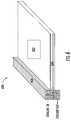
- FIG. 1illustrates example exploded views of the heat exchanger domains in accordance with various aspects described herein.
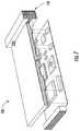
- FIG. 2illustrates example exploded views of the heat exchanger domains in accordance with various aspects described herein.
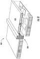
- FIG. 3illustrates an example trifurcated, multi-domain heat exchanger structure in accordance with various aspects described herein.
- FIG. 4illustrates an example trifurcated, multi-domain path representation in accordance with various aspects described herein.
- FIG. 5illustrates an example cross section of a three-dimensional conformal vapor chamber in accordance with various aspects described herein.
- FIG. 6illustrates an example schematic of a combined trifurcated heat exchanger and three-dimensional conformal vapor chamber in accordance with various aspects described herein.
- FIGS. 7-9illustrate example schematics of additional configurations of the combined trifurcated heat exchanger and three-dimensional conformal vapor chamber in accordance with various aspects described herein.
- FIG. 10illustrates an example schematic of additional configurations of the combined trifurcated heat exchanger and three-dimensional conformal vapor chamber having a vacuum shroud in accordance with various aspects described herein.
- first structurewhen a first structure is “substantially surrounding” a second structure, then the first structure surrounds at least 66% of the second structure. As used herein, when a first structure is “substantially surrounded by” a second structure, then at least 66% of the first structure is surrounded by the second structure.
- typical convection cooling systemsremove heat by transferring it from heat producing components to a series of fins. Air outside the fins lifts, carries away or otherwise removes the heat from the fins. In applications where the air outside the fins is not significantly hotter than the fins, a convection cooling system can be ineffective. For example, where the ambient environment is subject to additional heat producing components, the convection cooling system may be unable to effectively remove heat from the heat producing component to which it is coupled. Cooling the air via an air conditioning system can be inefficient, and require additional space and weight overhead.
- a first domain of the heat exchanger systemcan include a vapor chamber.
- a second domain of the heat exchanger systemcan include a fluid cooling (or heating) loop for providing efficient cooling (or heating) for the vapor chamber, and thus for an electronic component.
- a third domain of the heat exchanger systemcan include a phase change material.
- a fourth domain of the heat exchanger systemcan include a vacuum.
- the vapor chambercan be a three dimensional (3D) Conformal Vapor Chamber (CVC) configured in such a way that an evaporator section of the 3D CVC is closely mated to an electronic circuit board or to a set of electronic components (e.g., heat generating components), so that the 3D CVC can provide cooling to the electronic circuit board or set of electronic components.
- the evaporator section and a condenser section of the 3D CVCcan be configured to form the first domain of a heat exchanger system.
- the 3D CVC and the heat exchanger systemcan be realized in a single part, component or piece via additive manufacturing.
- the 3D CVC Evaporatoris connected to a 3D CVC condenser which forms one domain of a multi-domain (e.g., 2 or more domains) heat exchanger.
- a 3D CVC condenserwhich forms one domain of a multi-domain (e.g., 2 or more domains) heat exchanger.
- at least one of the remaining or other domains of the heat exchangercan be used to provide the 3D CVC condenser with a cooling fluid.
- at least one of the remaining heat exchanger domainscan be filled with a Phase Change Material (PCM).
- the PCMcan be of a reversible type (e.g., paraffin wax, etc.) or of the irreversible type (e.g., water being evaporated, with the vapor being dispersed into the environment). Virtually any PCM can be used within the scope of this innovation.
- at least one of the remaining heat exchanger domainscan be a vacuum.
- Some embodimentscan include a nested, trifurcated heat exchanger (HX) (or a trifurcated heat exchange portion), wherein the flow path for each fluid includes short flow lengths followed by hydrodynamic furcations that divide the flow and disrupt, interrupt or otherwise break the thermal boundary layer of the fluid.
- the pathscan combine with other adjacent sections to form a new or additional short path, and the division and recombination of paths can be repeated.
- a similar patternmay be followed by other fluid/volume(s) with thin walls separating each.
- the heat exchangercan be applied to two fluid systems by plumbing at least two of the fluid domains to the same fluid source. Likewise, the heat exchanger can be applied to 3 or more fluids.
- a further embodimentincludes using a phase change material in one of the volume domains, thus providing additional thermal capacitance over a particular temperature range.
- Other substances, or voids,can also be used as required in one or more of the volume domains.
- the trifurcated heat exchangercan be surrounded by a vacuum—the vacuum can be the fourth domain.
- example aspects of the present disclosurecan have a number of technical effects and benefits.
- example aspects of the present disclosurecan have a technical effect of cooling hot electronics to prevent damage to the electronics due to overheating.
- the systems and methods of the present disclosurealso provide an improvement to a computing system.
- the systemincludes a housing.
- a housingcan be an external wall surrounding one or more components.
- the housingincludes an evaporator portion.
- the housingincludes at least one trifurcated heat exchange portion.
- the at least one trifurcated heat exchange portionincludes a condenser portion coupled to the evaporator portion.
- the at least one trifurcated heat exchange portionincludes a coolant portion substantially surrounded by the condenser portion.
- the at least one trifurcated heat exchange portionincludes a phase change portion substantially surrounding the condenser portion. This can help prevent damage to electronics of the computing system due to overheating.
- the systemcan include a housing.
- the housingcan include an evaporator portion.
- the housingcan include at least one trifurcated heat exchange portion.
- the at least one trifurcated heat exchange portioncan include a condenser portion coupled to the evaporator portion.
- the at least one trifurcated heat exchange portioncan include a coolant portion substantially surrounded by the condenser portion.
- the at least one trifurcated heat exchange portioncan include a phase change portion substantially surrounding the condenser portion.
- At least one of the evaporator portion and the condenser portionincludes a heat exchange fluid. In some embodiments, at least one of the evaporator portion and the condenser portion includes at least one wall partially or fully lined with three dimensional conformal vapor chamber wicking structures.
- the phase change material portionincludes a phase change material. In some embodiments, the phase change material is of a reversible type. In some embodiments, the phase change material includes paraffin wax. In some embodiments, the phase change material is of an irreversible type. In some embodiments, the phase change material comprises water. In some embodiments, the housing can father include a vacuum portion.
- the systemcan include a first structure forming a first cavity. Coolant can be disposed in the first cavity.
- the systemcan include a second structure.
- a first chambercan be formed between at least portions of the first structure and at least portions of the second structure.
- the first chambercan include a heat transfer substance.
- the systemcan include a third structure.
- a second chambercan be formed between at least portions of the second structure and at least portions of the third structure.
- the second chambercan include a phase change material.
- the systemcan include a fourth structure forming a second cavity.
- the second cavitycan be in communication with the first chamber.
- the fourth structurecan be in communication with the surface.
- the second cavitycan include the heat transfer substance.
- At least one of the first chamber and the second cavityincludes a condenser. In some embodiments, at least one of the first chamber and the second cavity includes at least one wall partially or fully lined with three dimensional conformal vapor chamber wicking structures.
- the systemcan include a multi-phase heat exchanger.
- the systemcan include a heat spreader can include a three dimensional conformal vapor chamber.
- the three dimensional conformal vapor chamberis closely coupled with one or more multi-domain heat exchangers.
- at least one of the domainsincludes a condenser of the vapor chamber.
- at least one of the domainsincludes a coolant.
- at least one of the domainsincludes phase change material.
- the one or more multi-domain heat exchangersinclude three domains.
- at least one of the multi-phase heat exchanger and the three dimensional conformal vapor chamberare at least partially enclosed in a vacuum domain.
- the vacuum domainprovides thermal insulation between an environment and at least one of the multi-phase heat exchanger and the three dimensional conformal vapor chamber.
- a first structure 100can include a cavity 105 .
- the cavity 105can be a coolant portion.
- the cavity 105can include coolant 110 .
- a second structure 120can substantially surround the first structure 100 to form a first chamber 125 .
- the first chamber 125can be a condenser portion.
- the first chamber 125can be coupled to an evaporator portion.
- At least one of the evaporator portion and the condenser portioncan include a heat exchange fluid 130 .
- At least one of the evaporator portion and the condenser portioncan include at least one wall partially or fully lined with three dimensional conformal vapor chamber wicking structures.
- a second chamber, formed between a housing and the second structurecan be a phase change material portion.
- the phase change material portioncan include a phase change material 150 .
- the phase change material 150can be of a reversible type.
- the phase change material 150can be paraffin wax.
- the phase change material 150can be of an irreversible type.
- the phase change material 150can include water.
- FIG. 1one unit cell is represented; however, it is to be appreciated that virtually any number of unit cells can be replicated to provide adequate heat transfer surfaces within the scope of this innovation.
- FIG. 2illustrates how the coolant 200 can be shaped by a first cavity, how the heat exchange fluid 210 can be formed by the first chamber, and how the phase change material 220 can be formed by the second chamber.
- coolant 200 , heat exchange fluid 210 , and phase change material 220 manipulated by two unit cellsare represented; however, it is to be appreciated that virtually any number of unit cells can be replicated to provide adequate heat transfer surfaces within the scope of this innovation.
- FIG. 3illustrates example trifurcated, multi-domain heat exchanger structure 300 in accordance with various aspects described herein.
- the trifurcated, multi-domain heat exchanger structure 300can include a coolant portion 310 , a condenser portion 320 , and a phase change material portion 330 .
- eight unit cellsare represented; however, it is to be appreciated that virtually any number of unit cells can be replicated to provide adequate heat transfer surfaces within the scope of this innovation. Error! Reference source not found.
- FIG. 4illustrates example trifurcated, multi-domain heat exchanger path representations in accordance with various aspects described herein. Particularly, FIG. 4 illustrates a heat exchanger 400 , wherein separate fluid domains are illustrated.
- FIGS. 1-4illustrate three domains, virtually any quantity of domains are within the scope of the present innovation. Further, although FIGS. 1-4 illustrate three domains in a particular order (i.e., phase change material domain in the outermost layer, coolant domain in the innermost later, etc.), any or all of the three domains present in any order are within the scope of the present innovation.
- FIGS. 1-2illustrate example exploded views of the heat exchanger domains in accordance with various aspects described herein.
- FIG. 5illustrated is an example cross section of a three dimensional conformal vapor chamber (3D CVC) 500 in accordance with various aspects described herein.
- the cross sectionincludes an evaporator section 506 and condenser sections 508 of the 3D CVC 500 .
- the evaporator section 506can be in communication with hot components 502 , 504 .
- the 3D CVC 500can be an enclosed, hermetic vessel that has some or all of its internal surfaces lined with a wicking structure.
- the hermetic enclosureis initially evacuated and then charged with a measured amount of working fluid, for example distilled water. Due to the low pressure within the 3D CVC 500 , some of the working fluid will evaporate, until the vapor pressure brings the 3D CVC 500 to equilibrium.
- an evaporator section 506is illustrated as a center section, and the side sections are illustrated as the condenser sections 508 .
- Heatis represented by short-straight arrows going into or entering the evaporator section 506 .
- Vapor creationis represented by solid arrows in the evaporator section 506 and condenser sections 508 and liquid is represented by dashed arrows in the evaporator section 506 and condenser sections 508 , wherein evaporation of the fluid absorbs heat from the evaporator section 506 .
- the condenser sections 508are cooler than the evaporator section 506 , therefore the vapor condenses and deposits heat in the condenser sections 508 , as shown by the longer wavy arrows radiating away from the condenser sections 508 .
- one or more trifurcated nested heat exchangerscan replace a set of hollow fins used in a conventional heat exchanger arrangement.
- the interior walls of one of the HX fluid domainsfor example the condenser domain 420
- the condenser domain 420can be fully lined with 3D CVC wicking structures, and the condenser domain 420 can be terminated into a manifold that joins to the 3D CVC 500 in such a way that there is a continuous layer of wick throughout the whole 3D CVC 500 and the condenser domain 420 .
- the coolant domain 410can contain a cooling fluid, pumped from the outside of the HX and used to cool walls between the condenser domain 420 and the coolant domain 410 during normal operation.
- the phase change material domain 430can contain a phase change material (PCM), with a phase transition temperature higher than the normal temperature of the coolant.
- PCMphase change material
- a temperature of the coolantcan be low enough, and the mass flow can be high enough, to maintain the condenser domain 420 below the transition temperature of the PCM while extracting the heat generated by the heat generating components (e.g., electronics, etc.) connected to the evaporator section 506 and transported to the condenser section 508 by the vapor inside the 3D CVC 500 .
- trifurcated HX structurecan have a very large surface area (e.g., the interface between the condenser domain 420 and the phase change material domain 430 ) to the PCM, and the thickness of individual PCM sections can be small, so heat can be transferred into the PCM very efficiently, enabling its operation under large heat fluxes.
- Various sides of the trifurcated HXcan be configured to form manifolds for the various working fluids within the HX.
- the manifold that encompasses the PCM domaincan include an expansion area to allow for changes in volume of the PCM as it transitions through its phases.
- the PCM domaincan be sealed (e.g., in the case of a reversible PCM) or vented to the environment (e.g., in the case of an evaporative or ablative PCM).
- FIG. 6illustrates an example schematic of combined trifurcated heat exchanger (HX) and three dimensional conformal vapor chamber (3D CVC) 600 in accordance with various aspects described herein.
- a surface of a hot component 602can be in communication with a surface of an evaporator 604 of the combined trifurcated heat exchanger (HX) and three dimensional conformal vapor chamber (3D CVC) 600 .
- Vapor from the inside walls of the evaporator 604diffuses into a condenser section of the HX 606 , and condenses on either or both of an interface with a coolant section and an interface with a phase change material section.
- phase change material domaincontains a PCM that is hot (e.g., melted due to heat absorption), and the coolant domain is cool
- the interface with the phase change domaincan act as an evaporator, and the interface with the coolant domain can act as a condenser.
- FIG. 7illustrates an example HX and 3D CVC 700 like the one of FIG. 6 in communication with an electronic component 710 .
- the example HX and 3D CVC 700includes a housing 720 , an evaporator 730 , and a trifurcated heat exchanger 740 .
- FIG. 8illustrates an example HX and 3D CVC 800 with two evaporators 830 , each evaporator 830 in communication with an electronic component 810 .
- the example HX and 3D CVC 800further includes a housing 820 and a trifurcated heat exchanger 840 .
- FIG. 6illustrates the HX on one side, it can be on multiple sides, or all sides, and can be determined as a function of the amount desired to be subtracted or removed.
- FIG. 9illustrates an example HX and 3D CVC 900 with a HX 940 on multiples sides in communication with an electronic component 910 .
- the example HX and 3D CVC 900further includes a housing 920 and an evaporator 930 .
- FIG. 10illustrates an example HX and 3D CVC 1000 in communication with two electronic components 1010 .
- the example HX and 3D CVC 1000includes a housing 1020 , two evaporators, a trifurcated heat exchanger 1040 , and a vacuum domain 1050 . Portions or all of the device described in FIG.
- a vacuum domainor vacuum shroud
- the outermost domain of the nested Trifurcated HXcould be evacuated and sealed.
- an additional shroud encompassing the exterior of the nested trifurcated HXwould be additively manufactured and used to contain a vacuum (e.g., similar to a Dewar bottle). The areas of the device enclosed by the vacuum domain would vary with the application. Additionally, while three fluid domains are shown, multiple fluid domains can be used for the same fluid to create additional surface area.
- one fluid domaincan be connected to the vapor chamber, and the other two could be connected to a first fluid.
- one fluid domaincould be connected to the vapor chamber, and each of the other domains can include separate fluids.
- one domaincan include a phase change material, one domain can be connected to the vapor chamber, and another domain can contain a separate fluid.
- the multi-domain heat exchanger of the current innovationcan include virtually any number of domains.
- the multi-domain heat exchangercan include two domains, wherein one domain essentially acts as the condenser of a heat pipe, and the other domain includes coolant.
- a two domain heat exchangercan include any combination of the domains illustrated in FIG. 6 (e.g., any combination of fluids).
- the condenser domaincan be in virtually any domain, and can be selected based at least in part on the details of a particular application.
- the heat exchanger sectionscan be connected to multiple sides of the 3D CVC in quantities and shapes that fit the application. For example, if multiple HX sections are used, then the HX domains can be connected or separate, and the 3DCVC domains corresponding to the various HX sections can also be connected or separated. It is possible, in a single instantiation of this innovation, to have multiple 3D CVC domains each served by its own HX and combination of coolants and PCMs.
Landscapes
- Engineering & Computer Science (AREA)
- Physics & Mathematics (AREA)
- Thermal Sciences (AREA)
- Mechanical Engineering (AREA)
- General Engineering & Computer Science (AREA)
- Microelectronics & Electronic Packaging (AREA)
- Life Sciences & Earth Sciences (AREA)
- Sustainable Development (AREA)
- Condensed Matter Physics & Semiconductors (AREA)
- General Physics & Mathematics (AREA)
- Computer Hardware Design (AREA)
- Power Engineering (AREA)
- Geometry (AREA)
- Cooling Or The Like Of Semiconductors Or Solid State Devices (AREA)
- Cooling Or The Like Of Electrical Apparatus (AREA)
- Heat-Exchange Devices With Radiators And Conduit Assemblies (AREA)
Abstract
Description
Claims (20)
Priority Applications (1)
| Application Number | Priority Date | Filing Date | Title |
|---|---|---|---|
| US16/431,870US11035621B2 (en) | 2016-06-21 | 2019-06-05 | Electronics cooling with multi-phase heat exchange and heat spreader |
Applications Claiming Priority (3)
| Application Number | Priority Date | Filing Date | Title |
|---|---|---|---|
| US201662352862P | 2016-06-21 | 2016-06-21 | |
| US15/497,520US10365047B2 (en) | 2016-06-21 | 2017-04-26 | Electronics cooling with multi-phase heat exchange and heat spreader |
| US16/431,870US11035621B2 (en) | 2016-06-21 | 2019-06-05 | Electronics cooling with multi-phase heat exchange and heat spreader |
Related Parent Applications (1)
| Application Number | Title | Priority Date | Filing Date |
|---|---|---|---|
| US15/497,520ContinuationUS10365047B2 (en) | 2016-06-21 | 2017-04-26 | Electronics cooling with multi-phase heat exchange and heat spreader |
Publications (2)
| Publication Number | Publication Date |
|---|---|
| US20190285356A1 US20190285356A1 (en) | 2019-09-19 |
| US11035621B2true US11035621B2 (en) | 2021-06-15 |
Family
ID=60660019
Family Applications (3)
| Application Number | Title | Priority Date | Filing Date |
|---|---|---|---|
| US15/397,234Active2037-01-07US10209009B2 (en) | 2016-06-21 | 2017-01-03 | Heat exchanger including passageways |
| US15/497,520ActiveUS10365047B2 (en) | 2016-06-21 | 2017-04-26 | Electronics cooling with multi-phase heat exchange and heat spreader |
| US16/431,870Active2037-05-31US11035621B2 (en) | 2016-06-21 | 2019-06-05 | Electronics cooling with multi-phase heat exchange and heat spreader |
Family Applications Before (2)
| Application Number | Title | Priority Date | Filing Date |
|---|---|---|---|
| US15/397,234Active2037-01-07US10209009B2 (en) | 2016-06-21 | 2017-01-03 | Heat exchanger including passageways |
| US15/497,520ActiveUS10365047B2 (en) | 2016-06-21 | 2017-04-26 | Electronics cooling with multi-phase heat exchange and heat spreader |
Country Status (1)
| Country | Link |
|---|---|
| US (3) | US10209009B2 (en) |
Cited By (1)
| Publication number | Priority date | Publication date | Assignee | Title |
|---|---|---|---|---|
| US12352510B2 (en) | 2022-07-25 | 2025-07-08 | General Electric Company | Heat exchanger with a unit-cell |
Families Citing this family (48)
| Publication number | Priority date | Publication date | Assignee | Title |
|---|---|---|---|---|
| CA2962484A1 (en)* | 2014-10-07 | 2016-04-14 | Unison Industries, Llc | Multi-branch furcating flow heat exchanger |
| US10209009B2 (en)* | 2016-06-21 | 2019-02-19 | General Electric Company | Heat exchanger including passageways |
| WO2018045327A1 (en)* | 2016-09-01 | 2018-03-08 | Additive Rocket Corporation | Structural heat exchanger |
| US11747094B2 (en)* | 2017-05-12 | 2023-09-05 | The Boeing Company | Hollow lattice thermal energy storage heat exchanger |
| US10746479B2 (en) | 2018-02-09 | 2020-08-18 | General Electric Company | Additively manufactured structures for thermal and/or mechanical systems, and methods for manufacturing the structures |
| US11122715B2 (en) | 2018-05-11 | 2021-09-14 | General Electric Company | Conformal heat pipe assemblies |
| US11213923B2 (en)* | 2018-07-13 | 2022-01-04 | General Electric Company | Heat exchangers having a three-dimensional lattice structure with a rounded unit cell entrance and methods of forming rounded unit cell entrances in a three-dimensional lattice structure of a heat exchanger |
| US10955200B2 (en)* | 2018-07-13 | 2021-03-23 | General Electric Company | Heat exchangers having a three-dimensional lattice structure with baffle cells and methods of forming baffles in a three-dimensional lattice structure of a heat exchanger |
| US11076510B2 (en)* | 2018-08-13 | 2021-07-27 | Facebook Technologies, Llc | Heat management device and method of manufacture |
| JP7161354B2 (en)* | 2018-09-21 | 2022-10-26 | 住友精密工業株式会社 | Heat exchanger |
| US20200109901A1 (en)* | 2018-10-03 | 2020-04-09 | Raytheon Company | Additively manufactured thermal energy storage units |
| US11408684B1 (en) | 2018-10-11 | 2022-08-09 | Advanced Cooling Technologies, Inc. | Loop heat pipe evaporator |
| US10982553B2 (en) | 2018-12-03 | 2021-04-20 | General Electric Company | Tip rail with cooling structure using three dimensional unit cells |
| US11261738B2 (en)* | 2018-12-11 | 2022-03-01 | General Electric Company | Distributed nested cell damping system |
| US10948237B2 (en) | 2019-03-14 | 2021-03-16 | Raytheon Technologies Corporation | Method of creating a component via transformation of representative volume elements |
| US11267551B2 (en) | 2019-11-15 | 2022-03-08 | General Electric Company | System and method for cooling a leading edge of a high speed vehicle |
| US11260976B2 (en) | 2019-11-15 | 2022-03-01 | General Electric Company | System for reducing thermal stresses in a leading edge of a high speed vehicle |
| US11352120B2 (en) | 2019-11-15 | 2022-06-07 | General Electric Company | System and method for cooling a leading edge of a high speed vehicle |
| US11427330B2 (en) | 2019-11-15 | 2022-08-30 | General Electric Company | System and method for cooling a leading edge of a high speed vehicle |
| US11260953B2 (en) | 2019-11-15 | 2022-03-01 | General Electric Company | System and method for cooling a leading edge of a high speed vehicle |
| US12031501B2 (en) | 2019-11-27 | 2024-07-09 | General Electric Company | Cooling system for an engine assembly |
| US11561048B2 (en) | 2020-02-28 | 2023-01-24 | General Electric Company | Circular crossflow heat exchanger |
| US20210293483A1 (en)* | 2020-03-23 | 2021-09-23 | General Electric Company | Multifurcating heat exchanger with independent baffles |
| US11745847B2 (en) | 2020-12-08 | 2023-09-05 | General Electric Company | System and method for cooling a leading edge of a high speed vehicle |
| US11407488B2 (en) | 2020-12-14 | 2022-08-09 | General Electric Company | System and method for cooling a leading edge of a high speed vehicle |
| FR3119446B1 (en)* | 2021-02-04 | 2023-03-24 | Centre Nat Rech Scient | Condenser for heat pipe |
| US11577817B2 (en) | 2021-02-11 | 2023-02-14 | General Electric Company | System and method for cooling a leading edge of a high speed vehicle |
| US11804206B2 (en) | 2021-05-12 | 2023-10-31 | Goodrich Corporation | Acoustic panel for noise attenuation |
| US12104536B2 (en) | 2021-05-12 | 2024-10-01 | Rohr, Inc. | Nacelle liner comprising unit cell resonator networks |
| US12118971B2 (en) | 2021-05-12 | 2024-10-15 | B/E Aerospace, Inc. | Aircraft acoustic panel |
| US11830467B2 (en)* | 2021-10-16 | 2023-11-28 | Rtx Coroporation | Unit cell resonator networks for turbomachinery bypass flow structures |
| US11781485B2 (en) | 2021-11-24 | 2023-10-10 | Rtx Corporation | Unit cell resonator networks for gas turbine combustor tone damping |
| US12264627B2 (en) | 2022-03-02 | 2025-04-01 | General Electric Company | Heat exchanger for a gas turbine engine |
| US12071896B2 (en) | 2022-03-29 | 2024-08-27 | General Electric Company | Air-to-air heat exchanger potential in gas turbine engines |
| US11834995B2 (en) | 2022-03-29 | 2023-12-05 | General Electric Company | Air-to-air heat exchanger potential in gas turbine engines |
| JP2023150163A (en)* | 2022-03-31 | 2023-10-16 | 本田技研工業株式会社 | Heat exchanger and its manufacturing method |
| US12060829B2 (en) | 2022-04-27 | 2024-08-13 | General Electric Company | Heat exchanger capacity for one or more heat exchangers associated with an accessory gearbox of a turbofan engine |
| US11753995B1 (en) | 2022-04-27 | 2023-09-12 | General Electric Company | Hydrogen-exhaust gas heat exchanger of a turbofan engine |
| US12366204B2 (en) | 2022-04-27 | 2025-07-22 | General Electric Company | Heat exchanger capacity for one or more heat exchangers associated with a power gearbox of a turbofan engine |
| US11680530B1 (en) | 2022-04-27 | 2023-06-20 | General Electric Company | Heat exchanger capacity for one or more heat exchangers associated with a power gearbox of a turbofan engine |
| US12188415B2 (en) | 2022-04-27 | 2025-01-07 | General Electric Company | Hydrogen-exhaust gas heat exchanger of a turbofan engine |
| US11834992B2 (en) | 2022-04-27 | 2023-12-05 | General Electric Company | Heat exchanger capacity for one or more heat exchangers associated with an accessory gearbox of a turbofan engine |
| DE102022111769B4 (en)* | 2022-05-11 | 2024-01-18 | Rheinisch-Westfälische Technische Hochschule Aachen, Körperschaft des öffentlichen Rechts | Battery device |
| US12394804B2 (en) | 2022-08-16 | 2025-08-19 | General Electric Company | Thermal management of a fuel cell assembly |
| US12435932B2 (en)* | 2022-10-21 | 2025-10-07 | General Electric Company | Heat exchanger assembly formed of a lattice structure with a plurality of shell structure unit cells |
| US12312969B2 (en) | 2023-01-17 | 2025-05-27 | General Electric Company | Airfoils for turbofan engines |
| CN117968416A (en)* | 2024-04-01 | 2024-05-03 | 中国核动力研究设计院 | Three-way flow micro-channel compact heat exchanger and application method thereof |
| CN118066911B (en)* | 2024-04-24 | 2024-08-23 | 山东国创燃料电池技术创新中心有限公司 | Coupling heat exchanger suitable for high temperature system |
Citations (166)
| Publication number | Priority date | Publication date | Assignee | Title |
|---|---|---|---|---|
| US1020900A (en) | 1910-06-20 | 1912-03-19 | Artemus N Hadley | Oblique-angled gearing. |
| US2451692A (en) | 1946-02-19 | 1948-10-19 | Merlin L Pugh | Clothes drier |
| US3777975A (en) | 1971-03-03 | 1973-12-11 | Eberspaecher J | Space heater having a heating air flow duct with a heat exchanger for engine cooling water and one for combustion gases |
| US4111189A (en) | 1977-01-03 | 1978-09-05 | Cities Service Company | Combined solar radiation collector and thermal energy storage device |
| DE2837802A1 (en) | 1978-02-17 | 1979-08-23 | Hydro System Srl | Large surface area heat exchanger - has parallel or nested helical plastics tubes supported in end plates and connected to collectors |
| US4366526A (en) | 1980-10-03 | 1982-12-28 | Grumman Aerospace Corporation | Heat-pipe cooled electronic circuit card |
| US4419044A (en) | 1980-12-18 | 1983-12-06 | Rolls-Royce Limited | Gas turbine engine |
| US4700773A (en) | 1985-09-18 | 1987-10-20 | Borsig Gmbh | Nested-tube heat exchanger |
| US4771365A (en) | 1987-10-30 | 1988-09-13 | Honeywell Inc. | Passive cooled electronic chassis |
| US4915164A (en) | 1988-06-27 | 1990-04-10 | Harper Jr William H | Heat exchanger |
| US5060113A (en) | 1987-04-09 | 1991-10-22 | Raychem Corporation | Connector assembly |
| US5227957A (en) | 1992-05-14 | 1993-07-13 | Deters John B | Modular computer system with passive backplane |
| JPH0621290A (en) | 1991-12-02 | 1994-01-28 | Sun Microsyst Inc | Cooling apparatus of compact three- dimensional electronic device |
| US5283715A (en) | 1992-09-29 | 1994-02-01 | International Business Machines, Inc. | Integrated heat pipe and circuit board structure |
| US5343632A (en) | 1992-04-10 | 1994-09-06 | Advanced Dryer Systems, Inc. | Closed-loop drying process and system |
| DE2826998C1 (en) | 1977-07-22 | 1995-06-01 | Rolls Royce 1971 Ltd | Nozzle guide blade for a gas-turbine power plant |
| US5579830A (en) | 1995-11-28 | 1996-12-03 | Hudson Products Corporation | Passive cooling of enclosures using heat pipes |
| JPH094962A (en) | 1995-06-21 | 1997-01-10 | Hideo Masuda | Refrigerator with deep freezer using vacuum deep freezing chamber and vacuum cold storage chamber |
| US5647429A (en) | 1994-06-16 | 1997-07-15 | Oktay; Sevgin | Coupled, flux transformer heat pipes |
| US5720338A (en) | 1993-09-10 | 1998-02-24 | Aavid Laboratories, Inc. | Two-phase thermal bag component cooler |
| US5761909A (en) | 1996-12-16 | 1998-06-09 | The United States Of America As Represented By The Secretary Of The Navy | Breathing gas temperature modification device |
| JPH10267571A (en) | 1997-03-20 | 1998-10-09 | Furukawa Electric Co Ltd:The | Plate type heat pipe and cooling structure using it |
| CN1201704A (en) | 1997-05-20 | 1998-12-16 | 株式会社日立制作所 | Articles with a low-temperature hardening type highly active oxide photocatalyst thin film |
| US5899265A (en) | 1997-04-08 | 1999-05-04 | Sundstrand Corporation | Reflux cooler coupled with heat pipes to enhance load-sharing |
| US5975841A (en) | 1997-10-03 | 1999-11-02 | Thermal Corp. | Heat pipe cooling for turbine stators |
| EP1054583A2 (en) | 1999-05-20 | 2000-11-22 | TS Heatronics Co., Ltd. | Electronic components cooling apparatus |
| US6233150B1 (en) | 1998-12-28 | 2001-05-15 | Foxconn Precision Components Co., Ltd. | Memory module assembly |
| US6237223B1 (en) | 1999-05-06 | 2001-05-29 | Chip Coolers, Inc. | Method of forming a phase change heat sink |
| US6260613B1 (en) | 1999-01-05 | 2001-07-17 | Intel Corporation | Transient cooling augmentation for electronic components |
| US6269866B1 (en) | 1997-02-13 | 2001-08-07 | The Furukawa Electric Co., Ltd. | Cooling device with heat pipe |
| US20020021556A1 (en) | 1999-07-15 | 2002-02-21 | Dibene Joseph T. | Vapor chamber with integrated pin array |
| US6349760B1 (en) | 1999-10-22 | 2002-02-26 | Intel Corporation | Method and apparatus for improving the thermal performance of heat sinks |
| US6359218B1 (en) | 2000-04-04 | 2002-03-19 | Sun Microsystems, Inc. | Modular and expandable enclosure for electronic equipment |
| US6378605B1 (en) | 1999-12-02 | 2002-04-30 | Midwest Research Institute | Heat exchanger with transpired, highly porous fins |
| US6392883B1 (en) | 2000-06-30 | 2002-05-21 | Intel Corporation | Heat exchanger having phase change material for a portable computing device |
| US6430931B1 (en) | 1997-10-22 | 2002-08-13 | General Electric Company | Gas turbine in-line intercooler |
| US20020144811A1 (en) | 2001-01-13 | 2002-10-10 | Chou Der Jeou | Phase-change heat reservoir device for transient thermal management |
| US20020172010A1 (en) | 1999-12-28 | 2002-11-21 | Claude Sarno | Electronic module with high cooling power |
| US6498728B1 (en) | 1998-04-28 | 2002-12-24 | Thomson-Csf Sextant | Simplified modular structure |
| US20030043547A1 (en) | 2001-08-30 | 2003-03-06 | Nealis Edwin John | Modular electronics enclosure |
| US6624349B1 (en) | 2000-11-08 | 2003-09-23 | Hi-Z Technology, Inc. | Heat of fusion phase change generator |
| US6631755B1 (en) | 2002-07-17 | 2003-10-14 | Compal Electronics, Inc. | Thermal module with temporary heat storage |
| US20040074630A1 (en) | 2002-10-18 | 2004-04-22 | Sen Bidyut K. | Conformal heat spreader |
| US20040120116A1 (en) | 2002-12-19 | 2004-06-24 | Chad St. Louis | Embedded heat pipe for a conduction cooled circuit card assembly |
| US20040129032A1 (en) | 2000-06-05 | 2004-07-08 | The Procter & Gamble Company | Washing apparatus |
| US6793009B1 (en) | 2003-06-10 | 2004-09-21 | Thermal Corp. | CTE-matched heat pipe |
| US20040251006A1 (en) | 2003-04-03 | 2004-12-16 | Ovidiu Marin | Heat exchanger system for cooling optical fibers |
| US20050050877A1 (en) | 2003-09-05 | 2005-03-10 | Venkataramani Kattalaicheri Srinivasan | Methods and apparatus for operating gas turbine engines |
| US6889755B2 (en) | 2003-02-18 | 2005-05-10 | Thermal Corp. | Heat pipe having a wick structure containing phase change materials |
| US20050207120A1 (en) | 2004-03-16 | 2005-09-22 | Industrial Technology Research Institute | Thermal module with heat reservoir and method of applying the same on electronic products |
| US20050280162A1 (en) | 2004-06-18 | 2005-12-22 | International Business Machines Corporation | Thermal interposer for thermal management of semiconductor devices |
| US6983790B2 (en) | 2003-03-27 | 2006-01-10 | Mitsubishi Denki Kabushiki Kaisha | Heat transport device, semiconductor apparatus using the heat transport device and extra-atmospheric mobile unit using the heat transport device |
| US6994152B2 (en) | 2003-06-26 | 2006-02-07 | Thermal Corp. | Brazed wick for a heat transfer device |
| US20060042224A1 (en) | 2004-08-30 | 2006-03-02 | Daw Shien Scientific Research & Development, Inc. | Dual-plasma jet thruster with fuel cell |
| US7032654B2 (en) | 2003-08-19 | 2006-04-25 | Flatplate, Inc. | Plate heat exchanger with enhanced surface features |
| US20060140346A1 (en) | 2000-12-21 | 2006-06-29 | Mccarthy Joseph H Jr | Method and system for cooling heat-generating component in a closed-loop system |
| US20070012429A1 (en) | 2005-06-24 | 2007-01-18 | Convergence Technologies, Inc. | Heat Transfer Device |
| US20070017659A1 (en) | 2005-06-29 | 2007-01-25 | International Business Machines Corporation | Heat spreader |
| US20070040702A1 (en) | 2005-05-02 | 2007-02-22 | Mosher Todd J | Method for creating highly integrated satellite systems |
| US7189064B2 (en) | 2004-05-14 | 2007-03-13 | General Electric Company | Friction stir welded hollow airfoils and method therefor |
| US7256992B1 (en) | 2004-08-31 | 2007-08-14 | Sun Microsystems, Inc. | System for mounting and cooling circuit boards |
| US20070193723A1 (en) | 2006-02-17 | 2007-08-23 | Foxconn Technology Co., Ltd. | Heat pipe with capillary wick |
| TWI289655B (en) | 2006-06-23 | 2007-11-11 | Foxconn Tech Co Ltd | Heat pipe |
| US7307851B2 (en) | 1998-12-31 | 2007-12-11 | Honeywell International Inc. | Modified IMA cabinet architecture |
| US20080053640A1 (en) | 2006-08-31 | 2008-03-06 | International Business Machines Corporation | Compliant vapor chamber chip packaging |
| US7369410B2 (en) | 2006-05-03 | 2008-05-06 | International Business Machines Corporation | Apparatuses for dissipating heat from semiconductor devices |
| US7377098B2 (en) | 2004-08-26 | 2008-05-27 | United Technologies Corporation | Gas turbine engine frame with an integral fluid reservoir and air/fluid heat exchanger |
| US20080149299A1 (en) | 2006-12-20 | 2008-06-26 | Victor Blakemore Slaughter | Method of using minimal surfaces and minimal skeletons to make heat exchanger components |
| US20080235977A1 (en) | 2007-03-30 | 2008-10-02 | Sanyo Electric Co., Ltd. | Drying unit and laundry washing/drying machine equipped with the drying unit |
| US7473995B2 (en) | 2002-03-25 | 2009-01-06 | Intel Corporation | Integrated heat spreader, heat sink or heat pipe with pre-attached phase change thermal interface material and method of making an electronic assembly |
| US20090040726A1 (en) | 2007-08-09 | 2009-02-12 | Paul Hoffman | Vapor chamber structure and method for manufacturing the same |
| US20090244830A1 (en) | 2008-03-25 | 2009-10-01 | Raytheon Company | Systems and Methods for Cooling a Computing Component in a Computing Rack |
| US20100006132A1 (en) | 2008-07-14 | 2010-01-14 | Lucent Technologies, Inc. | Stacked Thermoelectric Modules |
| US20100065255A1 (en) | 2008-09-18 | 2010-03-18 | Pegatron Corporation | Vapor Chamber |
| US20100065256A1 (en) | 2008-09-12 | 2010-03-18 | Wilcoxon Ross K | Mechanically compliant thermal spreader with an embedded cooling loop for containing and circulating electrically-conductive liquid |
| US20100097767A1 (en) | 2008-10-18 | 2010-04-22 | John David Jude | Machine for passively removing heat generated by an electronic circuit board |
| US7704565B2 (en) | 2006-11-22 | 2010-04-27 | The Boeing Company | Method of making a layered component with vector discrimination in a variable deposition rate process |
| US20100170101A1 (en) | 2007-05-31 | 2010-07-08 | Panasonic Corporation | Cloth dryer |
| US20100181048A1 (en) | 2009-01-16 | 2010-07-22 | Furui Precise Component (Kunshan) Co., Ltd. | Heat pipe |
| US7768783B1 (en) | 2009-06-16 | 2010-08-03 | Microsoft Corporation | Electronic module cooling |
| US20100200199A1 (en) | 2006-03-03 | 2010-08-12 | Illuminex Corporation | Heat Pipe with Nanostructured Wick |
| US7836597B2 (en) | 2002-11-01 | 2010-11-23 | Cooligy Inc. | Method of fabricating high surface to volume ratio structures and their integration in microheat exchangers for liquid cooling system |
| US20100320187A1 (en) | 2009-06-17 | 2010-12-23 | Drs Test & Energy Management, Llc | Heat Sink and Thermal Plate Apparatus for Electronic Components |
| US7871578B2 (en) | 2005-05-02 | 2011-01-18 | United Technologies Corporation | Micro heat exchanger with thermally conductive porous network |
| US20110016886A1 (en) | 2008-03-05 | 2011-01-27 | Uttam Ghoshal | Method and apparatus for switched thermoelectric cooling of fluids |
| US7900438B2 (en) | 2006-07-28 | 2011-03-08 | General Electric Company | Heat transfer system and method for turbine engine using heat pipes |
| US7928562B2 (en) | 2008-07-22 | 2011-04-19 | International Business Machines Corporation | Segmentation of a die stack for 3D packaging thermal management |
| US7942025B1 (en) | 2002-05-03 | 2011-05-17 | Musone John P | Combined washer dryer |
| GB2476253A (en) | 2009-12-17 | 2011-06-22 | Rolls Royce Plc | Fuel Injector Cooled by a Heat Pipe |
| US20110209864A1 (en) | 2008-11-12 | 2011-09-01 | Astrium Sas | Thermal control device with network of interconnected capillary heat pipes |
| US20110232877A1 (en) | 2010-03-23 | 2011-09-29 | Celsia Technologies Taiwan, Inc. | Compact vapor chamber and heat-dissipating module having the same |
| US20110259041A1 (en) | 2010-04-21 | 2011-10-27 | Whirlpool Corporation | High efficiency condenser |
| US8047269B2 (en) | 2007-09-13 | 2011-11-01 | Tamkang University | Thermal spreader for simultaneously enhancing capillary effect and structural strength |
| US20120020017A1 (en) | 2010-07-20 | 2012-01-26 | Kehret William E | Printed circuit board module enclosure and apparatus using same |
| US8109324B2 (en) | 2005-04-14 | 2012-02-07 | Illinois Institute Of Technology | Microchannel heat exchanger with micro-encapsulated phase change material for high flux cooling |
| US20120036886A1 (en) | 2010-08-12 | 2012-02-16 | GM Global Technology Operations LLC | Internal heat exchanger for a motor vehicle air-conditioning system |
| US20120110869A1 (en) | 2010-11-08 | 2012-05-10 | Whirlpool Corporation | End of cycle detection for a laundry treating appliance |
| US20120125573A1 (en) | 2009-08-27 | 2012-05-24 | Brandon Rubenstein | Heat storage by phase-change material |
| US20120160449A1 (en) | 2010-12-27 | 2012-06-28 | Src, Inc. | Thermal transfer component, apparatus and method including thermally conductive frame penetrated by thermally conductive plug |
| US20120192574A1 (en) | 2009-07-17 | 2012-08-02 | Uttam Ghoshal | Heat Pipes And Thermoelectric Cooling Devices |
| US20120206880A1 (en) | 2011-02-14 | 2012-08-16 | Hamilton Sundstrand Corporation | Thermal spreader with phase change thermal capacitor for electrical cooling |
| US20120227926A1 (en) | 2009-11-16 | 2012-09-13 | Sunamp Limited | Energy storage systems |
| US20120250259A1 (en) | 2011-04-01 | 2012-10-04 | Academia Sinica | Cooling system for an electronic rack |
| US8323122B2 (en) | 2009-05-19 | 2012-12-04 | Cobra Golf Incorporated | Method of making golf clubs |
| US20120331269A1 (en) | 2009-12-24 | 2012-12-27 | Richard John Edward Aras | Geodesic Massively Parallel Computer. |
| US20130079693A1 (en) | 2011-09-26 | 2013-03-28 | Northeastern University | Customizable Embedded Sensors |
| DE102011086786B3 (en) | 2011-11-22 | 2013-03-28 | Mtu Aero Engines Gmbh | Cooling housing useful for accommodating electronic components, comprises heat pipes for cooling the electronic components, and are integrated with the cooling housing, and contain a liquid fluid that evaporates under heat absorption |
| US20130098417A1 (en) | 2010-06-23 | 2013-04-25 | Jerome Gavillet | Thermogenerator comprising phase-change materials |
| US20130105122A1 (en) | 2011-10-26 | 2013-05-02 | International Business Machines Corporation | Wicking vapor-condenser facilitating immersion-cooling of electronic component(s) |
| US8466486B2 (en) | 2010-08-27 | 2013-06-18 | Tsmc Solid State Lighting Ltd. | Thermal management system for multiple heat source devices |
| US8475112B1 (en) | 2007-11-29 | 2013-07-02 | Florida Turbine Technologies, Inc. | Multiple staged compressor with last stage airfoil cooling |
| WO2013097031A2 (en) | 2011-12-29 | 2013-07-04 | 7837003 Canada Inc. | Extraction from large thermal storage systems using phase change materials and latent heat exchangers |
| US20130189594A1 (en) | 2012-01-24 | 2013-07-25 | Joseph Sherman Breit | Utilizing phase change material, heat pipes, and fuel cells for aircraft applications |
| US20130206374A1 (en) | 2010-03-15 | 2013-08-15 | The Trustees Of Dartmouth College | Geometry of heat exchanger with high efficiency |
| US20130213610A1 (en) | 2012-02-22 | 2013-08-22 | Chun-Ming Wu | Heat pipe structure |
| US20130236299A1 (en) | 2012-03-06 | 2013-09-12 | Honeywell International Inc. | Tubular heat exchange systems |
| US8549749B2 (en) | 2004-10-25 | 2013-10-08 | Alliant Techsystems Inc. | Evaporators for use in heat transfer systems, apparatus including such evaporators and related methods |
| US20130268085A1 (en) | 2012-04-06 | 2013-10-10 | The University Of Liverpool | Surface modified unit cell lattice structures for optimized secure freeform fabrication |
| US20130327504A1 (en) | 2008-07-21 | 2013-12-12 | The Regents Of The University Of California | Titanium-based thermal ground plane |
| US8610761B2 (en) | 2009-11-09 | 2013-12-17 | Prohectionworks, Inc. | Systems and methods for optically projecting three-dimensional text, images and/or symbols onto three-dimensional objects |
| US8616834B2 (en) | 2010-04-30 | 2013-12-31 | General Electric Company | Gas turbine engine airfoil integrated heat exchanger |
| US20140014493A1 (en) | 2012-03-15 | 2014-01-16 | Robert C. Ryan | Minimal surface area mass and heat transfer packing |
| US20140037873A1 (en) | 2010-10-19 | 2014-02-06 | Massachusetts Institute Of Technology | Digital Flexural Materials |
| US8656722B2 (en) | 2007-06-13 | 2014-02-25 | United Technologies Corporation | Hybrid cooling of a gas turbine engine |
| US20140083653A1 (en) | 2012-09-26 | 2014-03-27 | Roger S. Kempers | Vapor-Based Heat Transfer Apparatus |
| US20140083651A1 (en) | 2012-09-21 | 2014-03-27 | Thales | Mechanical-thermal structure suitable for a space environment |
| US20140090808A1 (en) | 2011-05-17 | 2014-04-03 | Sharp Kabushiki Kaisha | Heat-transfer device |
| US20140150464A1 (en) | 2010-02-08 | 2014-06-05 | TOKITAE LLC, a limited liability company of the State of Delaware | Temperature-Stabilized Storage Systems with Integral Regulated Cooling |
| US20140163445A1 (en) | 2011-08-05 | 2014-06-12 | Materialise Nv | Lattice structure made by additive manufacturing |
| US20140158334A1 (en) | 2011-06-22 | 2014-06-12 | Commissariat A L'energie Atomique Et Aux Ene Alt | Thermal management system with variable-volume material |
| US20140169981A1 (en) | 2012-12-14 | 2014-06-19 | United Technologies Corporation | Uber-cooled turbine section component made by additive manufacturing |
| US20140174086A1 (en) | 2012-12-21 | 2014-06-26 | Elwha Llc | Heat engine system |
| US20140190667A1 (en) | 2011-05-24 | 2014-07-10 | Thermal Corp. | Capillary device for use in heat pipe and method of manufacturing such capillary device |
| US20140202665A1 (en) | 2013-01-22 | 2014-07-24 | Palo Alto Research Center Incorporated | Integrated thin film evaporation thermal spreader and planar heat pipe heat sink |
| US20140251585A1 (en) | 2013-03-05 | 2014-09-11 | The Boeing Company | Micro-lattice Cross-flow Heat Exchangers for Aircraft |
| US20140268831A1 (en) | 2013-03-12 | 2014-09-18 | Jun Zhan Technology Co., Ltd. | Heat dissipating device and illumination device having the same |
| US20140284020A1 (en) | 2012-01-24 | 2014-09-25 | The Boeing Company | Energy storage and thermal management using phase change materials in conjunction with heat pipes and foils, foams or other porous media |
| US20140321998A1 (en) | 2013-04-24 | 2014-10-30 | MTU Aero Engines AG | Housing section of a turbine engine compressor stage or turbine engine turbine stage |
| US20140340845A1 (en) | 2013-05-15 | 2014-11-20 | DY 4 Systems, Inc. | Fluid Cooled Enclosure For Circuit Module Apparatus And Methods Of Cooling A Conduction Cooled Circuit Module |
| US20150000871A1 (en) | 2013-07-01 | 2015-01-01 | Hamilton Sundstrand Corporation | Housing with heat pipes integrated into enclosure fins |
| US8934235B2 (en) | 2012-01-23 | 2015-01-13 | Microsoft Corporation | Heat transfer device with phase change material |
| US8937384B2 (en) | 2012-04-25 | 2015-01-20 | Qualcomm Incorporated | Thermal management of integrated circuits using phase change material and heat spreaders |
| US20150027669A1 (en) | 2013-07-26 | 2015-01-29 | Hamilton Sundstrand Corporation | Heat exchanger with embedded heat pipes |
| US20150040888A1 (en) | 2013-08-08 | 2015-02-12 | Solarno, Inc. | Integration of phase change materials inside evacuated tube solar collector for storage and transfer of thermal energy |
| US20150080495A1 (en) | 2013-07-11 | 2015-03-19 | Kurt E. Heikkila | Surface modified particulate and sintered or injection molded products |
| CN104776740A (en) | 2014-01-14 | 2015-07-15 | 江苏格业新材料科技有限公司 | Method for preparing high-efficiency micro heat tube by combining copper powder with copper oxide powder |
| US20150237762A1 (en) | 2014-02-20 | 2015-08-20 | Raytheon Company | Integrated thermal management system |
| US20150285501A1 (en) | 2014-04-08 | 2015-10-08 | General Electric Company | System for cooling a fuel injector extending into a combustion gas flow field and method for manufacture |
| US20150289413A1 (en) | 2014-04-08 | 2015-10-08 | General Electric Company | Systems and methods for using additive manufacturing for thermal management |
| US20150366105A1 (en) | 2014-06-12 | 2015-12-17 | Birchbridge Incorporated | Configurable heat transfer grids and related methods |
| US20150369545A1 (en) | 2013-01-18 | 2015-12-24 | Taisei Plas Co., Ltd. | Heat exchanger and method for manufacturing same |
| US20150375340A1 (en) | 2014-06-30 | 2015-12-31 | General Electric Company | Additive manufacturing methods and systems with fiber reinforcement |
| US20160069622A1 (en) | 2013-04-23 | 2016-03-10 | Alexiou & Tryde Holding Aps | Heat Sink Having a Cooling Structure with Decreasing Structure Density |
| WO2016057471A1 (en) | 2014-10-07 | 2016-04-14 | Unison Industries, Llc | Spiral wound cross-flow heat exchanger |
| US20160116218A1 (en) | 2014-10-27 | 2016-04-28 | Ebullient, Llc | Heat exchanger with helical passageways |
| US20160123678A1 (en) | 2014-11-04 | 2016-05-05 | i2C Solutions, LLC | Conformal thermal ground planes |
| US20160202003A1 (en) | 2014-10-07 | 2016-07-14 | General Electric Company | Heat exchanger including furcating unit cells |
| US20160305279A1 (en) | 2015-04-15 | 2016-10-20 | General Electric Company | Gas turbine engine component with integrated heat pipe |
| US9476651B2 (en) | 2014-12-15 | 2016-10-25 | General Electric Company | Thermal management system |
| US9516791B2 (en) | 2009-05-12 | 2016-12-06 | Iceotope Limited | Cooled electronic system |
| US20170064868A1 (en) | 2015-01-08 | 2017-03-02 | General Electric Company | System and method for thermal management using vapor chamber |
| US20170067693A1 (en) | 2015-09-09 | 2017-03-09 | General Electric Company | Thermal management system |
| US20170276440A1 (en) | 2016-03-25 | 2017-09-28 | Unison Industries, Llc | Heat exchanger |
| US9974157B2 (en) | 2016-08-15 | 2018-05-15 | General Electric Company | Circuit card cartridge for an electronic system |
| US20180356794A1 (en) | 2017-01-06 | 2018-12-13 | General Electric Company | Methods of defining internal structures for additive manufacturing |
| US10365047B2 (en)* | 2016-06-21 | 2019-07-30 | Ge Aviation Systems Llc | Electronics cooling with multi-phase heat exchange and heat spreader |
- 2017
- 2017-01-03USUS15/397,234patent/US10209009B2/enactiveActive
- 2017-04-26USUS15/497,520patent/US10365047B2/enactiveActive
- 2019
- 2019-06-05USUS16/431,870patent/US11035621B2/enactiveActive
Patent Citations (178)
| Publication number | Priority date | Publication date | Assignee | Title |
|---|---|---|---|---|
| US1020900A (en) | 1910-06-20 | 1912-03-19 | Artemus N Hadley | Oblique-angled gearing. |
| US2451692A (en) | 1946-02-19 | 1948-10-19 | Merlin L Pugh | Clothes drier |
| US3777975A (en) | 1971-03-03 | 1973-12-11 | Eberspaecher J | Space heater having a heating air flow duct with a heat exchanger for engine cooling water and one for combustion gases |
| US4111189A (en) | 1977-01-03 | 1978-09-05 | Cities Service Company | Combined solar radiation collector and thermal energy storage device |
| DE2826998C1 (en) | 1977-07-22 | 1995-06-01 | Rolls Royce 1971 Ltd | Nozzle guide blade for a gas-turbine power plant |
| US5439351A (en) | 1977-07-22 | 1995-08-08 | Rolls-Royce, Plc | Heat pipes |
| DE2837802A1 (en) | 1978-02-17 | 1979-08-23 | Hydro System Srl | Large surface area heat exchanger - has parallel or nested helical plastics tubes supported in end plates and connected to collectors |
| US4366526A (en) | 1980-10-03 | 1982-12-28 | Grumman Aerospace Corporation | Heat-pipe cooled electronic circuit card |
| US4419044A (en) | 1980-12-18 | 1983-12-06 | Rolls-Royce Limited | Gas turbine engine |
| US4700773A (en) | 1985-09-18 | 1987-10-20 | Borsig Gmbh | Nested-tube heat exchanger |
| US5060113A (en) | 1987-04-09 | 1991-10-22 | Raychem Corporation | Connector assembly |
| US4771365A (en) | 1987-10-30 | 1988-09-13 | Honeywell Inc. | Passive cooled electronic chassis |
| US4915164A (en) | 1988-06-27 | 1990-04-10 | Harper Jr William H | Heat exchanger |
| JPH0621290A (en) | 1991-12-02 | 1994-01-28 | Sun Microsyst Inc | Cooling apparatus of compact three- dimensional electronic device |
| US5343632A (en) | 1992-04-10 | 1994-09-06 | Advanced Dryer Systems, Inc. | Closed-loop drying process and system |
| US5227957A (en) | 1992-05-14 | 1993-07-13 | Deters John B | Modular computer system with passive backplane |
| US5283715A (en) | 1992-09-29 | 1994-02-01 | International Business Machines, Inc. | Integrated heat pipe and circuit board structure |
| US5720338A (en) | 1993-09-10 | 1998-02-24 | Aavid Laboratories, Inc. | Two-phase thermal bag component cooler |
| US5647429A (en) | 1994-06-16 | 1997-07-15 | Oktay; Sevgin | Coupled, flux transformer heat pipes |
| JPH094962A (en) | 1995-06-21 | 1997-01-10 | Hideo Masuda | Refrigerator with deep freezer using vacuum deep freezing chamber and vacuum cold storage chamber |
| US5579830A (en) | 1995-11-28 | 1996-12-03 | Hudson Products Corporation | Passive cooling of enclosures using heat pipes |
| US5761909A (en) | 1996-12-16 | 1998-06-09 | The United States Of America As Represented By The Secretary Of The Navy | Breathing gas temperature modification device |
| US6269866B1 (en) | 1997-02-13 | 2001-08-07 | The Furukawa Electric Co., Ltd. | Cooling device with heat pipe |
| JPH10267571A (en) | 1997-03-20 | 1998-10-09 | Furukawa Electric Co Ltd:The | Plate type heat pipe and cooling structure using it |
| US5899265A (en) | 1997-04-08 | 1999-05-04 | Sundstrand Corporation | Reflux cooler coupled with heat pipes to enhance load-sharing |
| CN1201704A (en) | 1997-05-20 | 1998-12-16 | 株式会社日立制作所 | Articles with a low-temperature hardening type highly active oxide photocatalyst thin film |
| US5975841A (en) | 1997-10-03 | 1999-11-02 | Thermal Corp. | Heat pipe cooling for turbine stators |
| US6430931B1 (en) | 1997-10-22 | 2002-08-13 | General Electric Company | Gas turbine in-line intercooler |
| US6498728B1 (en) | 1998-04-28 | 2002-12-24 | Thomson-Csf Sextant | Simplified modular structure |
| US6233150B1 (en) | 1998-12-28 | 2001-05-15 | Foxconn Precision Components Co., Ltd. | Memory module assembly |
| US7307851B2 (en) | 1998-12-31 | 2007-12-11 | Honeywell International Inc. | Modified IMA cabinet architecture |
| US6260613B1 (en) | 1999-01-05 | 2001-07-17 | Intel Corporation | Transient cooling augmentation for electronic components |
| US6237223B1 (en) | 1999-05-06 | 2001-05-29 | Chip Coolers, Inc. | Method of forming a phase change heat sink |
| US6360813B1 (en) | 1999-05-20 | 2002-03-26 | Ts Heatronics Co., Ltd. | Electronic components cooling apparatus |
| EP1054583A2 (en) | 1999-05-20 | 2000-11-22 | TS Heatronics Co., Ltd. | Electronic components cooling apparatus |
| US20020021556A1 (en) | 1999-07-15 | 2002-02-21 | Dibene Joseph T. | Vapor chamber with integrated pin array |
| US6349760B1 (en) | 1999-10-22 | 2002-02-26 | Intel Corporation | Method and apparatus for improving the thermal performance of heat sinks |
| US6378605B1 (en) | 1999-12-02 | 2002-04-30 | Midwest Research Institute | Heat exchanger with transpired, highly porous fins |
| US20020172010A1 (en) | 1999-12-28 | 2002-11-21 | Claude Sarno | Electronic module with high cooling power |
| US6359218B1 (en) | 2000-04-04 | 2002-03-19 | Sun Microsystems, Inc. | Modular and expandable enclosure for electronic equipment |
| US20040129032A1 (en) | 2000-06-05 | 2004-07-08 | The Procter & Gamble Company | Washing apparatus |
| US6392883B1 (en) | 2000-06-30 | 2002-05-21 | Intel Corporation | Heat exchanger having phase change material for a portable computing device |
| US6624349B1 (en) | 2000-11-08 | 2003-09-23 | Hi-Z Technology, Inc. | Heat of fusion phase change generator |
| US20060140346A1 (en) | 2000-12-21 | 2006-06-29 | Mccarthy Joseph H Jr | Method and system for cooling heat-generating component in a closed-loop system |
| US20020144811A1 (en) | 2001-01-13 | 2002-10-10 | Chou Der Jeou | Phase-change heat reservoir device for transient thermal management |
| US20030043547A1 (en) | 2001-08-30 | 2003-03-06 | Nealis Edwin John | Modular electronics enclosure |
| US7473995B2 (en) | 2002-03-25 | 2009-01-06 | Intel Corporation | Integrated heat spreader, heat sink or heat pipe with pre-attached phase change thermal interface material and method of making an electronic assembly |
| US7942025B1 (en) | 2002-05-03 | 2011-05-17 | Musone John P | Combined washer dryer |
| US6631755B1 (en) | 2002-07-17 | 2003-10-14 | Compal Electronics, Inc. | Thermal module with temporary heat storage |
| US20040011503A1 (en) | 2002-07-17 | 2004-01-22 | Shao-Tsu Kung | Thermal module with temporary heat storage |
| US20040074630A1 (en) | 2002-10-18 | 2004-04-22 | Sen Bidyut K. | Conformal heat spreader |
| US7007741B2 (en) | 2002-10-18 | 2006-03-07 | Sun Microsystems, Inc. | Conformal heat spreader |
| US7836597B2 (en) | 2002-11-01 | 2010-11-23 | Cooligy Inc. | Method of fabricating high surface to volume ratio structures and their integration in microheat exchangers for liquid cooling system |
| US20040120116A1 (en) | 2002-12-19 | 2004-06-24 | Chad St. Louis | Embedded heat pipe for a conduction cooled circuit card assembly |
| US6889755B2 (en) | 2003-02-18 | 2005-05-10 | Thermal Corp. | Heat pipe having a wick structure containing phase change materials |
| US6983790B2 (en) | 2003-03-27 | 2006-01-10 | Mitsubishi Denki Kabushiki Kaisha | Heat transport device, semiconductor apparatus using the heat transport device and extra-atmospheric mobile unit using the heat transport device |
| US20040251006A1 (en) | 2003-04-03 | 2004-12-16 | Ovidiu Marin | Heat exchanger system for cooling optical fibers |
| US6793009B1 (en) | 2003-06-10 | 2004-09-21 | Thermal Corp. | CTE-matched heat pipe |
| US6994152B2 (en) | 2003-06-26 | 2006-02-07 | Thermal Corp. | Brazed wick for a heat transfer device |
| US7032654B2 (en) | 2003-08-19 | 2006-04-25 | Flatplate, Inc. | Plate heat exchanger with enhanced surface features |
| US20050050877A1 (en) | 2003-09-05 | 2005-03-10 | Venkataramani Kattalaicheri Srinivasan | Methods and apparatus for operating gas turbine engines |
| US20050207120A1 (en) | 2004-03-16 | 2005-09-22 | Industrial Technology Research Institute | Thermal module with heat reservoir and method of applying the same on electronic products |
| US7189064B2 (en) | 2004-05-14 | 2007-03-13 | General Electric Company | Friction stir welded hollow airfoils and method therefor |
| US7002247B2 (en) | 2004-06-18 | 2006-02-21 | International Business Machines Corporation | Thermal interposer for thermal management of semiconductor devices |
| US20050280162A1 (en) | 2004-06-18 | 2005-12-22 | International Business Machines Corporation | Thermal interposer for thermal management of semiconductor devices |
| US7377098B2 (en) | 2004-08-26 | 2008-05-27 | United Technologies Corporation | Gas turbine engine frame with an integral fluid reservoir and air/fluid heat exchanger |
| US20060042224A1 (en) | 2004-08-30 | 2006-03-02 | Daw Shien Scientific Research & Development, Inc. | Dual-plasma jet thruster with fuel cell |
| US7256992B1 (en) | 2004-08-31 | 2007-08-14 | Sun Microsystems, Inc. | System for mounting and cooling circuit boards |
| US8549749B2 (en) | 2004-10-25 | 2013-10-08 | Alliant Techsystems Inc. | Evaporators for use in heat transfer systems, apparatus including such evaporators and related methods |
| US8109324B2 (en) | 2005-04-14 | 2012-02-07 | Illinois Institute Of Technology | Microchannel heat exchanger with micro-encapsulated phase change material for high flux cooling |
| US20070040702A1 (en) | 2005-05-02 | 2007-02-22 | Mosher Todd J | Method for creating highly integrated satellite systems |
| US7871578B2 (en) | 2005-05-02 | 2011-01-18 | United Technologies Corporation | Micro heat exchanger with thermally conductive porous network |
| US20070012429A1 (en) | 2005-06-24 | 2007-01-18 | Convergence Technologies, Inc. | Heat Transfer Device |
| US20130008632A1 (en) | 2005-06-29 | 2013-01-10 | International Business Machines Corporation | Heat spreader |
| US20070017659A1 (en) | 2005-06-29 | 2007-01-25 | International Business Machines Corporation | Heat spreader |
| US20070193723A1 (en) | 2006-02-17 | 2007-08-23 | Foxconn Technology Co., Ltd. | Heat pipe with capillary wick |
| US7594537B2 (en) | 2006-02-17 | 2009-09-29 | Foxconn Technology Co., Ltd. | Heat pipe with capillary wick |
| US20100200199A1 (en) | 2006-03-03 | 2010-08-12 | Illuminex Corporation | Heat Pipe with Nanostructured Wick |
| US7369410B2 (en) | 2006-05-03 | 2008-05-06 | International Business Machines Corporation | Apparatuses for dissipating heat from semiconductor devices |
| US20080170368A1 (en) | 2006-05-03 | 2008-07-17 | International Business Machines Corporation | Apparatuses for Dissipating Heat from Semiconductor Devices |
| TWI289655B (en) | 2006-06-23 | 2007-11-11 | Foxconn Tech Co Ltd | Heat pipe |
| US7900438B2 (en) | 2006-07-28 | 2011-03-08 | General Electric Company | Heat transfer system and method for turbine engine using heat pipes |
| US20080053640A1 (en) | 2006-08-31 | 2008-03-06 | International Business Machines Corporation | Compliant vapor chamber chip packaging |
| US8176972B2 (en) | 2006-08-31 | 2012-05-15 | International Business Machines Corporation | Compliant vapor chamber chip packaging |
| US7704565B2 (en) | 2006-11-22 | 2010-04-27 | The Boeing Company | Method of making a layered component with vector discrimination in a variable deposition rate process |
| US20080149299A1 (en) | 2006-12-20 | 2008-06-26 | Victor Blakemore Slaughter | Method of using minimal surfaces and minimal skeletons to make heat exchanger components |
| US20080235977A1 (en) | 2007-03-30 | 2008-10-02 | Sanyo Electric Co., Ltd. | Drying unit and laundry washing/drying machine equipped with the drying unit |
| US20100170101A1 (en) | 2007-05-31 | 2010-07-08 | Panasonic Corporation | Cloth dryer |
| US8656722B2 (en) | 2007-06-13 | 2014-02-25 | United Technologies Corporation | Hybrid cooling of a gas turbine engine |
| US20090040726A1 (en) | 2007-08-09 | 2009-02-12 | Paul Hoffman | Vapor chamber structure and method for manufacturing the same |
| US8047269B2 (en) | 2007-09-13 | 2011-11-01 | Tamkang University | Thermal spreader for simultaneously enhancing capillary effect and structural strength |
| US8475112B1 (en) | 2007-11-29 | 2013-07-02 | Florida Turbine Technologies, Inc. | Multiple staged compressor with last stage airfoil cooling |
| US20110016886A1 (en) | 2008-03-05 | 2011-01-27 | Uttam Ghoshal | Method and apparatus for switched thermoelectric cooling of fluids |
| US20090244830A1 (en) | 2008-03-25 | 2009-10-01 | Raytheon Company | Systems and Methods for Cooling a Computing Component in a Computing Rack |
| US7907409B2 (en) | 2008-03-25 | 2011-03-15 | Raytheon Company | Systems and methods for cooling a computing component in a computing rack |
| WO2009120613A1 (en) | 2008-03-25 | 2009-10-01 | Raytheon Company | Systems and methods for cooling a computing component in a computing rack |
| US20100006132A1 (en) | 2008-07-14 | 2010-01-14 | Lucent Technologies, Inc. | Stacked Thermoelectric Modules |
| US20130327504A1 (en) | 2008-07-21 | 2013-12-12 | The Regents Of The University Of California | Titanium-based thermal ground plane |
| US7928562B2 (en) | 2008-07-22 | 2011-04-19 | International Business Machines Corporation | Segmentation of a die stack for 3D packaging thermal management |
| US20100065256A1 (en) | 2008-09-12 | 2010-03-18 | Wilcoxon Ross K | Mechanically compliant thermal spreader with an embedded cooling loop for containing and circulating electrically-conductive liquid |
| US20100065255A1 (en) | 2008-09-18 | 2010-03-18 | Pegatron Corporation | Vapor Chamber |
| US20100097767A1 (en) | 2008-10-18 | 2010-04-22 | John David Jude | Machine for passively removing heat generated by an electronic circuit board |
| US20110209864A1 (en) | 2008-11-12 | 2011-09-01 | Astrium Sas | Thermal control device with network of interconnected capillary heat pipes |
| US20100181048A1 (en) | 2009-01-16 | 2010-07-22 | Furui Precise Component (Kunshan) Co., Ltd. | Heat pipe |
| US9516791B2 (en) | 2009-05-12 | 2016-12-06 | Iceotope Limited | Cooled electronic system |
| US8323122B2 (en) | 2009-05-19 | 2012-12-04 | Cobra Golf Incorporated | Method of making golf clubs |
| US7768783B1 (en) | 2009-06-16 | 2010-08-03 | Microsoft Corporation | Electronic module cooling |
| US20100320187A1 (en) | 2009-06-17 | 2010-12-23 | Drs Test & Energy Management, Llc | Heat Sink and Thermal Plate Apparatus for Electronic Components |
| US20120192574A1 (en) | 2009-07-17 | 2012-08-02 | Uttam Ghoshal | Heat Pipes And Thermoelectric Cooling Devices |
| US20120125573A1 (en) | 2009-08-27 | 2012-05-24 | Brandon Rubenstein | Heat storage by phase-change material |
| US8610761B2 (en) | 2009-11-09 | 2013-12-17 | Prohectionworks, Inc. | Systems and methods for optically projecting three-dimensional text, images and/or symbols onto three-dimensional objects |
| US20120227926A1 (en) | 2009-11-16 | 2012-09-13 | Sunamp Limited | Energy storage systems |
| GB2476253A (en) | 2009-12-17 | 2011-06-22 | Rolls Royce Plc | Fuel Injector Cooled by a Heat Pipe |
| US20120331269A1 (en) | 2009-12-24 | 2012-12-27 | Richard John Edward Aras | Geodesic Massively Parallel Computer. |
| US20140150464A1 (en) | 2010-02-08 | 2014-06-05 | TOKITAE LLC, a limited liability company of the State of Delaware | Temperature-Stabilized Storage Systems with Integral Regulated Cooling |
| US20130206374A1 (en) | 2010-03-15 | 2013-08-15 | The Trustees Of Dartmouth College | Geometry of heat exchanger with high efficiency |
| US20110232877A1 (en) | 2010-03-23 | 2011-09-29 | Celsia Technologies Taiwan, Inc. | Compact vapor chamber and heat-dissipating module having the same |
| US20110259041A1 (en) | 2010-04-21 | 2011-10-27 | Whirlpool Corporation | High efficiency condenser |
| US8616834B2 (en) | 2010-04-30 | 2013-12-31 | General Electric Company | Gas turbine engine airfoil integrated heat exchanger |
| US20130098417A1 (en) | 2010-06-23 | 2013-04-25 | Jerome Gavillet | Thermogenerator comprising phase-change materials |
| US20120020017A1 (en) | 2010-07-20 | 2012-01-26 | Kehret William E | Printed circuit board module enclosure and apparatus using same |
| US20120036886A1 (en) | 2010-08-12 | 2012-02-16 | GM Global Technology Operations LLC | Internal heat exchanger for a motor vehicle air-conditioning system |
| US8466486B2 (en) | 2010-08-27 | 2013-06-18 | Tsmc Solid State Lighting Ltd. | Thermal management system for multiple heat source devices |
| US20140037873A1 (en) | 2010-10-19 | 2014-02-06 | Massachusetts Institute Of Technology | Digital Flexural Materials |
| US20120110869A1 (en) | 2010-11-08 | 2012-05-10 | Whirlpool Corporation | End of cycle detection for a laundry treating appliance |
| US20120160449A1 (en) | 2010-12-27 | 2012-06-28 | Src, Inc. | Thermal transfer component, apparatus and method including thermally conductive frame penetrated by thermally conductive plug |
| US20120206880A1 (en) | 2011-02-14 | 2012-08-16 | Hamilton Sundstrand Corporation | Thermal spreader with phase change thermal capacitor for electrical cooling |
| US20120250259A1 (en) | 2011-04-01 | 2012-10-04 | Academia Sinica | Cooling system for an electronic rack |
| US20140090808A1 (en) | 2011-05-17 | 2014-04-03 | Sharp Kabushiki Kaisha | Heat-transfer device |
| US20140190667A1 (en) | 2011-05-24 | 2014-07-10 | Thermal Corp. | Capillary device for use in heat pipe and method of manufacturing such capillary device |
| US20140158334A1 (en) | 2011-06-22 | 2014-06-12 | Commissariat A L'energie Atomique Et Aux Ene Alt | Thermal management system with variable-volume material |
| US20140163445A1 (en) | 2011-08-05 | 2014-06-12 | Materialise Nv | Lattice structure made by additive manufacturing |
| US20130079693A1 (en) | 2011-09-26 | 2013-03-28 | Northeastern University | Customizable Embedded Sensors |
| US20130105122A1 (en) | 2011-10-26 | 2013-05-02 | International Business Machines Corporation | Wicking vapor-condenser facilitating immersion-cooling of electronic component(s) |
| DE102011086786B3 (en) | 2011-11-22 | 2013-03-28 | Mtu Aero Engines Gmbh | Cooling housing useful for accommodating electronic components, comprises heat pipes for cooling the electronic components, and are integrated with the cooling housing, and contain a liquid fluid that evaporates under heat absorption |
| WO2013097031A2 (en) | 2011-12-29 | 2013-07-04 | 7837003 Canada Inc. | Extraction from large thermal storage systems using phase change materials and latent heat exchangers |
| US8934235B2 (en) | 2012-01-23 | 2015-01-13 | Microsoft Corporation | Heat transfer device with phase change material |
| US20130189594A1 (en) | 2012-01-24 | 2013-07-25 | Joseph Sherman Breit | Utilizing phase change material, heat pipes, and fuel cells for aircraft applications |
| US20140284020A1 (en) | 2012-01-24 | 2014-09-25 | The Boeing Company | Energy storage and thermal management using phase change materials in conjunction with heat pipes and foils, foams or other porous media |
| US20130213610A1 (en) | 2012-02-22 | 2013-08-22 | Chun-Ming Wu | Heat pipe structure |
| US20130236299A1 (en) | 2012-03-06 | 2013-09-12 | Honeywell International Inc. | Tubular heat exchange systems |
| US20140014493A1 (en) | 2012-03-15 | 2014-01-16 | Robert C. Ryan | Minimal surface area mass and heat transfer packing |
| US20130268085A1 (en) | 2012-04-06 | 2013-10-10 | The University Of Liverpool | Surface modified unit cell lattice structures for optimized secure freeform fabrication |
| US8937384B2 (en) | 2012-04-25 | 2015-01-20 | Qualcomm Incorporated | Thermal management of integrated circuits using phase change material and heat spreaders |
| US20140083651A1 (en) | 2012-09-21 | 2014-03-27 | Thales | Mechanical-thermal structure suitable for a space environment |
| US20140083653A1 (en) | 2012-09-26 | 2014-03-27 | Roger S. Kempers | Vapor-Based Heat Transfer Apparatus |
| US20140169981A1 (en) | 2012-12-14 | 2014-06-19 | United Technologies Corporation | Uber-cooled turbine section component made by additive manufacturing |
| US20140174086A1 (en) | 2012-12-21 | 2014-06-26 | Elwha Llc | Heat engine system |
| US20150369545A1 (en) | 2013-01-18 | 2015-12-24 | Taisei Plas Co., Ltd. | Heat exchanger and method for manufacturing same |
| US20140202665A1 (en) | 2013-01-22 | 2014-07-24 | Palo Alto Research Center Incorporated | Integrated thin film evaporation thermal spreader and planar heat pipe heat sink |
| US20140251585A1 (en) | 2013-03-05 | 2014-09-11 | The Boeing Company | Micro-lattice Cross-flow Heat Exchangers for Aircraft |
| US20140268831A1 (en) | 2013-03-12 | 2014-09-18 | Jun Zhan Technology Co., Ltd. | Heat dissipating device and illumination device having the same |
| US20160069622A1 (en) | 2013-04-23 | 2016-03-10 | Alexiou & Tryde Holding Aps | Heat Sink Having a Cooling Structure with Decreasing Structure Density |
| US20140321998A1 (en) | 2013-04-24 | 2014-10-30 | MTU Aero Engines AG | Housing section of a turbine engine compressor stage or turbine engine turbine stage |
| US20140340845A1 (en) | 2013-05-15 | 2014-11-20 | DY 4 Systems, Inc. | Fluid Cooled Enclosure For Circuit Module Apparatus And Methods Of Cooling A Conduction Cooled Circuit Module |
| US20150000871A1 (en) | 2013-07-01 | 2015-01-01 | Hamilton Sundstrand Corporation | Housing with heat pipes integrated into enclosure fins |
| US20150080495A1 (en) | 2013-07-11 | 2015-03-19 | Kurt E. Heikkila | Surface modified particulate and sintered or injection molded products |
| US20150027669A1 (en) | 2013-07-26 | 2015-01-29 | Hamilton Sundstrand Corporation | Heat exchanger with embedded heat pipes |
| US20150040888A1 (en) | 2013-08-08 | 2015-02-12 | Solarno, Inc. | Integration of phase change materials inside evacuated tube solar collector for storage and transfer of thermal energy |
| CN104776740A (en) | 2014-01-14 | 2015-07-15 | 江苏格业新材料科技有限公司 | Method for preparing high-efficiency micro heat tube by combining copper powder with copper oxide powder |
| US20150237762A1 (en) | 2014-02-20 | 2015-08-20 | Raytheon Company | Integrated thermal management system |
| US20150285501A1 (en) | 2014-04-08 | 2015-10-08 | General Electric Company | System for cooling a fuel injector extending into a combustion gas flow field and method for manufacture |
| US20150289413A1 (en) | 2014-04-08 | 2015-10-08 | General Electric Company | Systems and methods for using additive manufacturing for thermal management |
| US20150366105A1 (en) | 2014-06-12 | 2015-12-17 | Birchbridge Incorporated | Configurable heat transfer grids and related methods |
| US20150375340A1 (en) | 2014-06-30 | 2015-12-31 | General Electric Company | Additive manufacturing methods and systems with fiber reinforcement |
| US20160202003A1 (en) | 2014-10-07 | 2016-07-14 | General Electric Company | Heat exchanger including furcating unit cells |
| WO2016057471A1 (en) | 2014-10-07 | 2016-04-14 | Unison Industries, Llc | Spiral wound cross-flow heat exchanger |
| USD818093S1 (en) | 2014-10-07 | 2018-05-15 | General Electric Company | Heat exchanger including furcating unit cells |
| US20160116218A1 (en) | 2014-10-27 | 2016-04-28 | Ebullient, Llc | Heat exchanger with helical passageways |
| US20160123678A1 (en) | 2014-11-04 | 2016-05-05 | i2C Solutions, LLC | Conformal thermal ground planes |
| US9476651B2 (en) | 2014-12-15 | 2016-10-25 | General Electric Company | Thermal management system |
| US20170064868A1 (en) | 2015-01-08 | 2017-03-02 | General Electric Company | System and method for thermal management using vapor chamber |
| US20160305279A1 (en) | 2015-04-15 | 2016-10-20 | General Electric Company | Gas turbine engine component with integrated heat pipe |
| US20170067693A1 (en) | 2015-09-09 | 2017-03-09 | General Electric Company | Thermal management system |
| US20170276440A1 (en) | 2016-03-25 | 2017-09-28 | Unison Industries, Llc | Heat exchanger |
| US10365047B2 (en)* | 2016-06-21 | 2019-07-30 | Ge Aviation Systems Llc | Electronics cooling with multi-phase heat exchange and heat spreader |
| US9974157B2 (en) | 2016-08-15 | 2018-05-15 | General Electric Company | Circuit card cartridge for an electronic system |
| US20180356794A1 (en) | 2017-01-06 | 2018-12-13 | General Electric Company | Methods of defining internal structures for additive manufacturing |
Non-Patent Citations (47)
| Title |
|---|
| Air Pollution Control Technology Fact Sheet, Wet Electrostatic Precipitator (ESP) Wire-Pipe Type, EPA-452/F-03-029, Retrieved from Internet URL: https://www3.epa.gov/ttnchiel/mkb/documents/fwespwpi.pdf , Oct. 23, 2018, pp. 1-4. |
| Ameli et al., A Novel Method for Manufacturing Sintered Aluminum Heat Pipes (SAHP), Applied Thermal Engineering, vol. No. 52, Issue No. 2, Apr. 15, 2013, pp. 498-504. |
| Arif-Uz-Zaman et al., A Novel Dehumidification Technique Using Electric Field, IEEE Transactions on Industry Applications, vol. 32, Issue 1, Jan./Feb. 1996, pp. 36-40. |
| Battery Prognostics—Prognosis Framework, National Aeronautics and Space Administration, Retrieved from Internet URL: http://ti.arc.nasa.gointech/dash/pcoe/battery-pragnosis-framev.orW May 8, 2014, pp. 1-3. |
| Bendt, Are We Missing Energy Savings in Clothes Dryers?, ACEEE Summer Study on Energy Efficiency in Buildings, 2010, pp. 9-42 through 9-55. |
| Brackett et al., Topology Optimization for Additive Manufacturing, Wolfson School of Mechanical and Manufacturing Engineering, Loughborough University, Aug. 17, 2011, Loughborough, Leicestershire, LE11 3TU, UK, pp. 348-362. |
| Brotan et al., The hybrid manufacturing cell: Determining key parameters in the integration of powder bed fusion with high speed milling, Industrial Engineering and Engineering Management (IEEM), 2012 IEEE International Conference on Dec. 10-13, 2012, Hong Kong, pp. 583-587. |
| Brown et al., Thermal management issues and evaluation of a novel, flexible substrate, 3-dimensional (3-D) packaging concept, Multichip Modules and High Density Packaging, 1998 Proceedings International Conference on Apr. 15-17, 1998, Denver, CO, pp. 135-140. |
| Buckley et al., Application Of Wet Electrostatic Precipitation Technology In The Utility Industry For Multiple Pollutant Control Including Mercury, Croll-Reynolds Clean Air Technologies, 2003, pp. 1-14. |
| Buekens, Electrostatic Precipitators, Pollution Control Technologies, Encyclopedia of Life Support Systems (EOLSS), vol. 1, 2008, pp. 1-9. |
| Building Energy Efficiency Frontiers and Incubator Technologies (Benefit), Funding Opportunity Announcement (FOA) No. DE-FOA-0001027, 2014, pp. 1-94. |
| Combined Search and Examination Report issued in Connection with Corresponding GB Application No. 17129032 dated Dec. 11, 2017. |
| De Bock et al., Circuit Card Cartridge for an Electronic System, GE Co-Pending U.S. Appl. No. 14/592,387, filed Aug. 4, 2016. |
| Energy Star, Emerging Technology Award Requirements: Advanced Dryers, Retrieved from Internet URL: http://www.energystart.gov/ia/partners/pt_awards/documents/2012_Energy_Start_Emerging_Technology_Award_Advanced_Clothes_Dryers_Requirements.pdf?5dbd-3858&877d-d14f on Oct. 18, 2018, p. 1 (Feb. 9, 2012). |
| Engineers guide to military aerospace and avionics, Application Solutions, Extension Media, 2014, p. 36. |
| EP Office Action dated Dec. 21, 2018 for corresponding Application No. 171845266-1103. |
| Erno et al., Multi-branch furcating flow heat exchanger, GE Co-Pending U.S. Appl. No. 62/060,719, filed Oct. 7, 2014. |
| European Search Report and Opinion issued in connection with Corresponding EP Application No. 151626702 dated Aug. 24, 2015. |
| European Search Report and Written Opinion issued in connection with related EP Application No. 161652508 dated Sep. 14, 2016. |
| Extended European Search Report and Opinion Issued in Connection with Corresponding EP Application No. 171845266 dated Nov. 29, 2017. |
| Gerstler et al., Systems and methods for using additive manufacturing for thermal management, GE Co-Pending U.S. Appl. No. 61/976,649, filed Apr. 8, 2014. |
| Great Britain Combined Search and Examination Report Issued in Connection with Corresponding EP Application No. 16149072 dated Jan. 24, 2017. |
| Great Britain Office Action issued in Connection with Corresponding GB Application No. GB16149072 dated Mar. 20, 2018. |
| Great Britain Office Action Issued in Connection with Corresponding GB Application No. GB16149072 dated Oct. 20, 2017. |
| Green et al., Dynamic Thermal management of high heat flux devices using embedded solid-liquid phase change materials and solid state coolers, 13th IEEE Intersociety Conference on May 30, 2012-Jun. 1, 2012, pp. 853-862. |
| Gu et al., Laser Additive Manufacturing of Metallic Components: Materials, Processes and Mechanisms, International Materials Review, vol. 57, No. 3, 2012, pp. 1-33. |
| Hara et al., Optimization for Chip Stack in 3-D Packaging, Advanced Packaging, IEEE Transactions, vol. 28, Issue 3.2, Aug. 2005, pp. 367-376. |
| Lee et al., Ventless Drying—The New Standard of Efficiency, Retrieved from the Internet URL: http://thorwasherdryers.blogspot.in/2010/07/fil.e-most-coomon-nisconceptions about html, on Oct. 18, 2018, pp. 1-2 (Jul. 30, 2010). |
| Mochizuki et al., A Review of Heat Pipe Application including New Opportunities, Frontiers in Heat Pipes, vol. 2, 2011, pp. 1-15. |
| Non-Final Rejection towards related U.S. Appl. No. 15/228,336 dated May 9, 2017. |
| Notification of Reasons for Refusal issued in connection with Corresponding JP Application No. 2015-076415 dated Nov. 27, 2018. |
| Pingsheng et al, Effect of Charge on Growth of Droplets with Ionic Condensation Nuclei, Chinese Science Bulletin, vol. 56, No. 18, Jun. 2011, pp. 1942-1946. |
| Radiant Heating with Infrared—A Technical Guide to Understanding and Applying Infrared Heaters, Watlow Electric Manufacturing Company, 1997, pp. 1-39. |
| Rawal et al., Thermal management for multifunctional structures, Advanced Packaging, IEEE Transactions on Aug. 1999, vol. 22 , Issue 3, Denver, CO, pp. 379-383. |
| Residential Clothes Dryers, Energy Star Market & Industry Scoping Report: Dryers, Nov. 2011, pp. 1-18. |
| Reznikov et al., Corona discharge in the steam for electrostatically enforced condensation, Proceedings 2012 Electrostatics Joint Conference, Jun. 2012, pp. 1-4. |
| Reznikov et al., Electrohydrodynamic Enforcement of Evaporation and Gas Flow, IEEE Transactions on Industry Applications, vol. 47, No. 2, Mar./Apr. 2011, pp. 1036-1042. |
| Robak, Latent Heat Thermal Energy Storage with Embedded Heat Pipes for Concentrating Solar Power Applications, University of Connecticut Digital Commons, Apr. 24, 2012, pp. 1-57. |
| Salazar et al., Electrospray as an Enforcement of Steam Condensation, Proc. ESA Annual Meeting on Electrostatics, 2013, pp. 1-10. |
| Stoffregen et al., Selective Laser Melting of Porous Structures, 2011, pp. 680-695. |
| Subracks, Pixus Technologies, Aug. 24, 2017, pp. 1-13. |
| Tapuchi et al., Obtaining Fresh Water from Atmosphere using Electrostatic Precipitation: Theory, Efficiency and limitations, E-Water, Official Publication of the European Water Association (EWA), 2010, pp. 1-6. |
| Winter, Engineers Guide to Military, Aerospace & Avionics, Extension Media, 2014, pp. 1-40. |
| Wu et al., Investigation of the Polymer Wick Structure Applied to Loop Heat Pipe, 2009 4th International Microsystems, Packaging, Assembly and Circuits Technology Conference, Oct. 21-23, 2009, pp. 368-371. |
| Yang, Corona-Driven Air Propulsion for Cooling of Microelectronics, Master of Science in Electrical Engineering, Mamishev et al., eds. 2002, pp. 1-81. |
| Yap et al., Review of Selective Laser Melting: Materials and Applications, Journal of Applied Physics, vol. 2, No. 4, 2015, pp. 1-21. |
| Yogev et al., PCM Storage System with Integrated Active Heat Pipe, Energy Procedia, vol. 49, 2014, pp. 1061-1070. |
Cited By (1)
| Publication number | Priority date | Publication date | Assignee | Title |
|---|---|---|---|---|
| US12352510B2 (en) | 2022-07-25 | 2025-07-08 | General Electric Company | Heat exchanger with a unit-cell |
Also Published As
| Publication number | Publication date |
|---|---|
| US20170367218A1 (en) | 2017-12-21 |
| US10209009B2 (en) | 2019-02-19 |
| US10365047B2 (en) | 2019-07-30 |
| US20190285356A1 (en) | 2019-09-19 |
| US20170363363A1 (en) | 2017-12-21 |
Similar Documents
| Publication | Publication Date | Title |
|---|---|---|
| US11035621B2 (en) | Electronics cooling with multi-phase heat exchange and heat spreader | |
| CN101307996B (en) | Flat-plate evaporator structure and loop type heat pipe with same | |
| EP3907455B1 (en) | Phase-change heat dissipation device | |
| US20070227703A1 (en) | Evaporatively cooled thermosiphon | |
| CN108882654B (en) | Phase change cooling system, cooling system and converter cabinet cooling system | |
| Attia et al. | Experimental investigation of vapor chamber with different working fluids at different charge ratios | |
| JP6564596B2 (en) | Lithium ion secondary battery device | |
| JP5681487B2 (en) | Heat pipe dissipation system and method | |
| WO2010017091A1 (en) | Microscale cooling apparatus and method | |
| CN106784441A (en) | It is a kind of for the radiating case lid of electric automobile battery box and its application | |
| US20220142001A1 (en) | Loop thermosyphon devices and systems, and related methods | |
| JP4953075B2 (en) | heatsink | |
| WO2006105220A1 (en) | Systems for improved passive liquid cooling | |
| CN104154787A (en) | Multi-stage evaporation micro-channel heat pipe heat transferring and radiating device | |
| CN213878214U (en) | Capillary pumping type plate evaporator for battery heat dissipation | |
| JP2007263427A (en) | Loop type heat pipe | |
| CN117810600A (en) | Uniform temperature heat radiation structure and battery assembly | |
| CN111818756B (en) | Heat exchanger with integrated two-phase radiator | |
| JP3549933B2 (en) | Plate fin type element cooler | |
| Fourgeaud et al. | Experimental investigations of a Multi-Source Loop Heat Pipe for electronics cooling | |
| CN107094361B (en) | A flat micro-circulation heat pipe with an upper cover plate and a chamber | |
| CN220307626U (en) | Loop heat pipe radiating element, device and electronic equipment | |
| CN115209692B (en) | Heat dissipation for electronic equipment and servers | |
| WO2023081401A1 (en) | Cooling device having a boiling chamber with submerged condensation and method | |
| CN207382775U (en) | A water-cooled phase change heat dissipation device |
Legal Events
| Date | Code | Title | Description |
|---|---|---|---|
| AS | Assignment | Owner name:GE AVIATION SYSTEMS LLC, MICHIGAN Free format text:ASSIGNMENT OF ASSIGNORS INTEREST;ASSIGNORS:LASSINI, STEFANO;RUSH, BRIAN;ERNO, DANIEL;AND OTHERS;SIGNING DATES FROM 20170413 TO 20170425;REEL/FRAME:049375/0351 | |
| FEPP | Fee payment procedure | Free format text:ENTITY STATUS SET TO UNDISCOUNTED (ORIGINAL EVENT CODE: BIG.); ENTITY STATUS OF PATENT OWNER: LARGE ENTITY | |
| STPP | Information on status: patent application and granting procedure in general | Free format text:DOCKETED NEW CASE - READY FOR EXAMINATION | |
| STPP | Information on status: patent application and granting procedure in general | Free format text:NOTICE OF ALLOWANCE MAILED -- APPLICATION RECEIVED IN OFFICE OF PUBLICATIONS | |
| STPP | Information on status: patent application and granting procedure in general | Free format text:PUBLICATIONS -- ISSUE FEE PAYMENT RECEIVED | |
| STPP | Information on status: patent application and granting procedure in general | Free format text:PUBLICATIONS -- ISSUE FEE PAYMENT VERIFIED | |
| STCF | Information on status: patent grant | Free format text:PATENTED CASE | |
| MAFP | Maintenance fee payment | Free format text:PAYMENT OF MAINTENANCE FEE, 4TH YEAR, LARGE ENTITY (ORIGINAL EVENT CODE: M1551); ENTITY STATUS OF PATENT OWNER: LARGE ENTITY Year of fee payment:4 |