US11035511B2 - Quick-change end effector - Google Patents
Quick-change end effectorDownload PDFInfo
- Publication number
- US11035511B2 US11035511B2US16/000,137US201816000137AUS11035511B2US 11035511 B2US11035511 B2US 11035511B2US 201816000137 AUS201816000137 AUS 201816000137AUS 11035511 B2US11035511 B2US 11035511B2
- Authority
- US
- United States
- Prior art keywords
- nozzle
- inlet
- channel
- adhesive
- end effector
- Prior art date
- Legal status (The legal status is an assumption and is not a legal conclusion. Google has not performed a legal analysis and makes no representation as to the accuracy of the status listed.)
- Active
Links
Images


Classifications
- F—MECHANICAL ENGINEERING; LIGHTING; HEATING; WEAPONS; BLASTING
- F16—ENGINEERING ELEMENTS AND UNITS; GENERAL MEASURES FOR PRODUCING AND MAINTAINING EFFECTIVE FUNCTIONING OF MACHINES OR INSTALLATIONS; THERMAL INSULATION IN GENERAL
- F16L—PIPES; JOINTS OR FITTINGS FOR PIPES; SUPPORTS FOR PIPES, CABLES OR PROTECTIVE TUBING; MEANS FOR THERMAL INSULATION IN GENERAL
- F16L37/00—Couplings of the quick-acting type
- F16L37/62—Couplings of the quick-acting type pneumatically or hydraulically actuated
- B—PERFORMING OPERATIONS; TRANSPORTING
- B05—SPRAYING OR ATOMISING IN GENERAL; APPLYING FLUENT MATERIALS TO SURFACES, IN GENERAL
- B05B—SPRAYING APPARATUS; ATOMISING APPARATUS; NOZZLES
- B05B1/00—Nozzles, spray heads or other outlets, with or without auxiliary devices such as valves, heating means
- B05B1/22—Spouts
- B—PERFORMING OPERATIONS; TRANSPORTING
- B05—SPRAYING OR ATOMISING IN GENERAL; APPLYING FLUENT MATERIALS TO SURFACES, IN GENERAL
- B05B—SPRAYING APPARATUS; ATOMISING APPARATUS; NOZZLES
- B05B15/00—Details of spraying plant or spraying apparatus not otherwise provided for; Accessories
- B05B15/60—Arrangements for mounting, supporting or holding spraying apparatus
- B05B15/65—Mounting arrangements for fluid connection of the spraying apparatus or its outlets to flow conduits
- B—PERFORMING OPERATIONS; TRANSPORTING
- B05—SPRAYING OR ATOMISING IN GENERAL; APPLYING FLUENT MATERIALS TO SURFACES, IN GENERAL
- B05B—SPRAYING APPARATUS; ATOMISING APPARATUS; NOZZLES
- B05B7/00—Spraying apparatus for discharge of liquids or other fluent materials from two or more sources, e.g. of liquid and air, of powder and gas
- B05B7/16—Spraying apparatus for discharge of liquids or other fluent materials from two or more sources, e.g. of liquid and air, of powder and gas incorporating means for heating or cooling the material to be sprayed
- B05B7/22—Spraying apparatus for discharge of liquids or other fluent materials from two or more sources, e.g. of liquid and air, of powder and gas incorporating means for heating or cooling the material to be sprayed electrically, magnetically or electromagnetically, e.g. by arc
- B05B7/228—Spraying apparatus for discharge of liquids or other fluent materials from two or more sources, e.g. of liquid and air, of powder and gas incorporating means for heating or cooling the material to be sprayed electrically, magnetically or electromagnetically, e.g. by arc using electromagnetic radiation, e.g. laser
- B—PERFORMING OPERATIONS; TRANSPORTING
- B22—CASTING; POWDER METALLURGY
- B22F—WORKING METALLIC POWDER; MANUFACTURE OF ARTICLES FROM METALLIC POWDER; MAKING METALLIC POWDER; APPARATUS OR DEVICES SPECIALLY ADAPTED FOR METALLIC POWDER
- B22F10/00—Additive manufacturing of workpieces or articles from metallic powder
- B22F10/20—Direct sintering or melting
- B22F10/25—Direct deposition of metal particles, e.g. direct metal deposition [DMD] or laser engineered net shaping [LENS]
- B—PERFORMING OPERATIONS; TRANSPORTING
- B22—CASTING; POWDER METALLURGY
- B22F—WORKING METALLIC POWDER; MANUFACTURE OF ARTICLES FROM METALLIC POWDER; MAKING METALLIC POWDER; APPARATUS OR DEVICES SPECIALLY ADAPTED FOR METALLIC POWDER
- B22F10/00—Additive manufacturing of workpieces or articles from metallic powder
- B22F10/20—Direct sintering or melting
- B22F10/28—Powder bed fusion, e.g. selective laser melting [SLM] or electron beam melting [EBM]
- B—PERFORMING OPERATIONS; TRANSPORTING
- B23—MACHINE TOOLS; METAL-WORKING NOT OTHERWISE PROVIDED FOR
- B23K—SOLDERING OR UNSOLDERING; WELDING; CLADDING OR PLATING BY SOLDERING OR WELDING; CUTTING BY APPLYING HEAT LOCALLY, e.g. FLAME CUTTING; WORKING BY LASER BEAM
- B23K26/00—Working by laser beam, e.g. welding, cutting or boring
- B23K26/34—Laser welding for purposes other than joining
- B—PERFORMING OPERATIONS; TRANSPORTING
- B23—MACHINE TOOLS; METAL-WORKING NOT OTHERWISE PROVIDED FOR
- B23K—SOLDERING OR UNSOLDERING; WELDING; CLADDING OR PLATING BY SOLDERING OR WELDING; CUTTING BY APPLYING HEAT LOCALLY, e.g. FLAME CUTTING; WORKING BY LASER BEAM
- B23K26/00—Working by laser beam, e.g. welding, cutting or boring
- B23K26/352—Working by laser beam, e.g. welding, cutting or boring for surface treatment
- B23K26/354—Working by laser beam, e.g. welding, cutting or boring for surface treatment by melting
- B—PERFORMING OPERATIONS; TRANSPORTING
- B33—ADDITIVE MANUFACTURING TECHNOLOGY
- B33Y—ADDITIVE MANUFACTURING, i.e. MANUFACTURING OF THREE-DIMENSIONAL [3-D] OBJECTS BY ADDITIVE DEPOSITION, ADDITIVE AGGLOMERATION OR ADDITIVE LAYERING, e.g. BY 3-D PRINTING, STEREOLITHOGRAPHY OR SELECTIVE LASER SINTERING
- B33Y40/00—Auxiliary operations or equipment, e.g. for material handling
- B—PERFORMING OPERATIONS; TRANSPORTING
- B33—ADDITIVE MANUFACTURING TECHNOLOGY
- B33Y—ADDITIVE MANUFACTURING, i.e. MANUFACTURING OF THREE-DIMENSIONAL [3-D] OBJECTS BY ADDITIVE DEPOSITION, ADDITIVE AGGLOMERATION OR ADDITIVE LAYERING, e.g. BY 3-D PRINTING, STEREOLITHOGRAPHY OR SELECTIVE LASER SINTERING
- B33Y80/00—Products made by additive manufacturing
- B—PERFORMING OPERATIONS; TRANSPORTING
- B62—LAND VEHICLES FOR TRAVELLING OTHERWISE THAN ON RAILS
- B62D—MOTOR VEHICLES; TRAILERS
- B62D27/00—Connections between superstructure or understructure sub-units
- B62D27/02—Connections between superstructure or understructure sub-units rigid
- B62D27/023—Assembly of structural joints
- F—MECHANICAL ENGINEERING; LIGHTING; HEATING; WEAPONS; BLASTING
- F16—ENGINEERING ELEMENTS AND UNITS; GENERAL MEASURES FOR PRODUCING AND MAINTAINING EFFECTIVE FUNCTIONING OF MACHINES OR INSTALLATIONS; THERMAL INSULATION IN GENERAL
- F16L—PIPES; JOINTS OR FITTINGS FOR PIPES; SUPPORTS FOR PIPES, CABLES OR PROTECTIVE TUBING; MEANS FOR THERMAL INSULATION IN GENERAL
- F16L21/00—Joints with sleeve or socket
- F16L21/08—Joints with sleeve or socket with additional locking means
- B—PERFORMING OPERATIONS; TRANSPORTING
- B05—SPRAYING OR ATOMISING IN GENERAL; APPLYING FLUENT MATERIALS TO SURFACES, IN GENERAL
- B05B—SPRAYING APPARATUS; ATOMISING APPARATUS; NOZZLES
- B05B12/00—Arrangements for controlling delivery; Arrangements for controlling the spray area
- B05B12/14—Arrangements for controlling delivery; Arrangements for controlling the spray area for supplying a selected one of a plurality of liquids or other fluent materials or several in selected proportions to a spray apparatus, e.g. to a single spray outlet
- B05B12/1472—Arrangements for controlling delivery; Arrangements for controlling the spray area for supplying a selected one of a plurality of liquids or other fluent materials or several in selected proportions to a spray apparatus, e.g. to a single spray outlet separate supply lines supplying different materials to separate outlets of the spraying apparatus
- B—PERFORMING OPERATIONS; TRANSPORTING
- B05—SPRAYING OR ATOMISING IN GENERAL; APPLYING FLUENT MATERIALS TO SURFACES, IN GENERAL
- B05B—SPRAYING APPARATUS; ATOMISING APPARATUS; NOZZLES
- B05B13/00—Machines or plants for applying liquids or other fluent materials to surfaces of objects or other work by spraying, not covered by groups B05B1/00 - B05B11/00
- B05B13/02—Means for supporting work; Arrangement or mounting of spray heads; Adaptation or arrangement of means for feeding work
- B05B13/04—Means for supporting work; Arrangement or mounting of spray heads; Adaptation or arrangement of means for feeding work the spray heads being moved during spraying operation
- B05B13/0431—Means for supporting work; Arrangement or mounting of spray heads; Adaptation or arrangement of means for feeding work the spray heads being moved during spraying operation with spray heads moved by robots or articulated arms, e.g. for applying liquid or other fluent material to three-dimensional [3D] surfaces
- B—PERFORMING OPERATIONS; TRANSPORTING
- B22—CASTING; POWDER METALLURGY
- B22F—WORKING METALLIC POWDER; MANUFACTURE OF ARTICLES FROM METALLIC POWDER; MAKING METALLIC POWDER; APPARATUS OR DEVICES SPECIALLY ADAPTED FOR METALLIC POWDER
- B22F10/00—Additive manufacturing of workpieces or articles from metallic powder
- B22F10/10—Formation of a green body
- B22F10/18—Formation of a green body by mixing binder with metal in filament form, e.g. fused filament fabrication [FFF]
- B—PERFORMING OPERATIONS; TRANSPORTING
- B22—CASTING; POWDER METALLURGY
- B22F—WORKING METALLIC POWDER; MANUFACTURE OF ARTICLES FROM METALLIC POWDER; MAKING METALLIC POWDER; APPARATUS OR DEVICES SPECIALLY ADAPTED FOR METALLIC POWDER
- B22F10/00—Additive manufacturing of workpieces or articles from metallic powder
- B22F10/20—Direct sintering or melting
- B—PERFORMING OPERATIONS; TRANSPORTING
- B22—CASTING; POWDER METALLURGY
- B22F—WORKING METALLIC POWDER; MANUFACTURE OF ARTICLES FROM METALLIC POWDER; MAKING METALLIC POWDER; APPARATUS OR DEVICES SPECIALLY ADAPTED FOR METALLIC POWDER
- B22F10/00—Additive manufacturing of workpieces or articles from metallic powder
- B22F10/80—Data acquisition or data processing
- B—PERFORMING OPERATIONS; TRANSPORTING
- B22—CASTING; POWDER METALLURGY
- B22F—WORKING METALLIC POWDER; MANUFACTURE OF ARTICLES FROM METALLIC POWDER; MAKING METALLIC POWDER; APPARATUS OR DEVICES SPECIALLY ADAPTED FOR METALLIC POWDER
- B22F12/00—Apparatus or devices specially adapted for additive manufacturing; Auxiliary means for additive manufacturing; Combinations of additive manufacturing apparatus or devices with other processing apparatus or devices
- B22F12/50—Means for feeding of material, e.g. heads
- B22F12/53—Nozzles
- B—PERFORMING OPERATIONS; TRANSPORTING
- B22—CASTING; POWDER METALLURGY
- B22F—WORKING METALLIC POWDER; MANUFACTURE OF ARTICLES FROM METALLIC POWDER; MAKING METALLIC POWDER; APPARATUS OR DEVICES SPECIALLY ADAPTED FOR METALLIC POWDER
- B22F5/00—Manufacture of workpieces or articles from metallic powder characterised by the special shape of the product
- B22F5/10—Manufacture of workpieces or articles from metallic powder characterised by the special shape of the product of articles with cavities or holes, not otherwise provided for in the preceding subgroups
- B—PERFORMING OPERATIONS; TRANSPORTING
- B33—ADDITIVE MANUFACTURING TECHNOLOGY
- B33Y—ADDITIVE MANUFACTURING, i.e. MANUFACTURING OF THREE-DIMENSIONAL [3-D] OBJECTS BY ADDITIVE DEPOSITION, ADDITIVE AGGLOMERATION OR ADDITIVE LAYERING, e.g. BY 3-D PRINTING, STEREOLITHOGRAPHY OR SELECTIVE LASER SINTERING
- B33Y10/00—Processes of additive manufacturing
- Y—GENERAL TAGGING OF NEW TECHNOLOGICAL DEVELOPMENTS; GENERAL TAGGING OF CROSS-SECTIONAL TECHNOLOGIES SPANNING OVER SEVERAL SECTIONS OF THE IPC; TECHNICAL SUBJECTS COVERED BY FORMER USPC CROSS-REFERENCE ART COLLECTIONS [XRACs] AND DIGESTS
- Y02—TECHNOLOGIES OR APPLICATIONS FOR MITIGATION OR ADAPTATION AGAINST CLIMATE CHANGE
- Y02P—CLIMATE CHANGE MITIGATION TECHNOLOGIES IN THE PRODUCTION OR PROCESSING OF GOODS
- Y02P10/00—Technologies related to metal processing
- Y02P10/25—Process efficiency
Definitions
- the present disclosuregenerally relates to additively manufactured end effectors, and more specifically to additively manufactured end effectors for fluid interfaces in additively manufactured nodes.
- Nodesperform important connection functions between various components in transport structures.
- the nodesmay be bonded to other components including tubes, extrusions, panels, and other nodes.
- nodescan be used to perform connections for panels.
- a transport structuresuch as an automobile, truck or aircraft employs a large number of interior and exterior panels. Most panels must be coupled to, or interface with, other panels or other structures in secure, well-designed ways. These connection types may be accomplished by using nodes.
- the nodes, or joint membersmay serve not only to attach to, interface with, and secure the panel, but they also may be used to form connections to other components of the automobile (e.g., another panel, an extrusion, tubes, other nodes, etc.).
- end effectors for interfacing with nozzles of the nodeshas several problems.
- the end effectorsare often specialized structures requiring intricate sub-substructures. It is often extremely difficult to manufacture these types of complex structures efficiently or cheaply using traditional manufacturing processes.
- the manufacturing processthere are a large number of nodes, the conventional interfaces with the nozzles of the nodes may be too time consuming and may not be efficient for mass assembly.
- End effectors for interfacing with the nozzles of the nodes, including the nodes for transport structures, and the additive manufacture thereofwill be described more fully hereinafter with reference to various illustrative aspects of the present disclosure.
- an end effector for interfacing with a nozzlecomprises a first end, which includes a receptacle.
- the receptacleis configured to receive the nozzle.
- the nozzleincludes one or more nozzle retention features and a first nozzle inlet.
- the end effectorcomprises one or more retention features positioned along a perimeter of the receptacle, where each of the one or more retention features is movable between a first position and a second position.
- Each of the one or more retention featuresis configured to lock the nozzle by securing onto a corresponding one of the one or more nozzle retention features in the first position, and to release the nozzle in the second position.
- the end effectormay further comprise one or more actuators configured to actuate the one or more retention features between the first position and the second position.
- the end effectorcomprises a first channel, which includes a first inlet and a first outlet. The first outlet is positioned inside the receptacle and is configured to be coupled to the first nozzle inlet in the first position.
- a method of using an end effector to interface with a nozzlecomprises receiving the nozzle in a receptacle of the end effector.
- the methodcomprises actuating one or more retention features of the end effector to a first position to secure onto a corresponding one of one or more nozzle retention features to lock the nozzle.
- the methodcomprises applying vacuum to a second inlet of the end effector, where a second outlet of the end effector is coupled to a second nozzle inlet.
- the methodcomprises injecting a first fluid to a first inlet of the end effector, wherein a first outlet of the end effector is coupled to a first nozzle inlet.
- FIG. 1illustrates an exemplary embodiment of certain aspects of a Direct Metal Deposition (DMD) 3-D printer.
- DMDDirect Metal Deposition
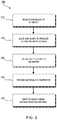
- FIG. 2illustrates a conceptual flow diagram of a 3-D printing process using a 3-D printer.
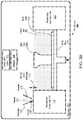
- FIGS. 3A-Dillustrate an exemplary powder bed fusion (PBF) system during different stages of operation.
- PPFpowder bed fusion
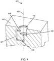
- FIG. 4illustrates a cross-section view of an example of a single port node for bonding to various components.
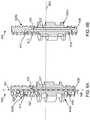
- FIG. 5Aillustrates a cross-section view of a two-channel nozzle for the single port node in FIG. 4 .
- FIG. 5Billustrates a perspective view of the two-channel nozzle in FIG. 5A .
- FIG. 6Aillustrates a cross-section view of a three-channel nozzle for the single port node in FIG. 4 .
- FIG. 6Billustrates another cross-section view of the three-channel nozzle in FIG. 6A .
- FIG. 7Aillustrates a nozzle including a plurality of regions for receiving O-Rings/sealants.
- FIG. 7Billustrates a bottom view of a nozzle with a plurality of third outlets.
- FIG. 7Cillustrates a bottom view of a nozzle with a plurality of third outlets.
- FIG. 8is a flow diagram of an example method of using a single port node.
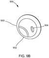
- FIG. 9Aillustrates a perspective view of an example of a single port node for bonding to various components.
- FIG. 9Billustrates a top view of the single port node in FIG. 9A .
- FIG. 9Cillustrates another perspective view of the single port node in FIG. 9A .
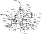
- FIG. 10illustrates a side view of an example of an end effector for interfacing with a nozzle according to one embodiment of this disclosure.
- FIG. 11Aillustrates a top view of the end effector in FIG. 10 in a first position.
- FIG. 11Billustrates another top view of the end effector in FIG. 10 in a second position.
- FIG. 12illustrates a perspective view of the end effector in FIG. 10 .
- FIG. 13is a flow diagram of an example method of using an end effector to interface with a nozzle.
- the end effectorcomprises a first end, which includes a receptacle.
- the receptacleis configured to receive the nozzle.
- the nozzleincludes one or more nozzle retention features and a first nozzle inlet.
- the end effectorcomprises one or more retention features positioned along a perimeter of the receptacle, where each of the one or more retention features is movable between a first position and a second position.
- Each of the one or more retention featuresis configured to lock the nozzle by securing onto a corresponding one of the one or more nozzle retention features in the first position, and to release the nozzle in the second position.
- the end effectormay further comprise one or more actuators configured to actuate the one or more retention features between the first position and the second position.
- the end effectorcomprises a first channel, which includes a first inlet and a first outlet. The first outlet is positioned inside the receptacle and is configured to be coupled to the first nozzle inlet in the first position.
- the nodes, and other structures described in this disclosuremay be formed using additive manufacturing (AM) techniques, due in part to AM's innumerable advantages as articulated below. Accordingly, certain exemplary AM techniques that may be relevant to the formation of the nodes described herein will initially be discussed. It should be understood, however, that numerous alternative manufacturing techniques, both additive and conventional, may instead be used in forming the nodes (in part or in whole) disclosed herein, and that the identified nodes need not be limited to the specific AM techniques below.
- AMadditive manufacturing
- Those that stand to benefit from the structures and techniques in this disclosureinclude, among others, manufacturers of virtually any mechanized form of transport, which often rely heavily on complex and labor-intensive tooling, and whose products often require the development of nodes, panels, and interconnects to be integrated with intricate machinery such as combustion engines, transmissions and increasingly sophisticated electronics.
- Examples of such transport structuresinclude, among others, trucks, trains, tractors, boats, aircraft, motorcycles, busses, and the like.
- Additive Manufacturing(3-D Printing).
- AMadditive manufacturing
- a nodeis a structural member that may include one or more interfaces used to connect to other spanning components such as tubes, extrusions, panels, other nodes, and the like.
- a nodemay be constructed to include additional features and functions, depending on the objectives. For example, a node may be printed with one or more ports that enable the node to secure two parts by injecting an adhesive rather than welding multiple parts together, as is traditionally done in manufacturing complex products.
- AMprovides significant flexibility in enabling the use of alternative or additional connection techniques.
- AMprovides the platform to print components with complex internal channels and geometries, some of which are impossible to manufacture using conventional manufacturing techniques.
- a variety of different AM techniqueshave been used to 3-D print components composed of various types of materials. Numerous available techniques exist, and more are being developed. For example, Directed Energy Deposition (DED) AM systems use directed energy sourced from laser or electron beams to melt metal. These systems utilize both powder and wire feeds. The wire feed systems advantageously have higher deposition rates than other prominent AM techniques.
- DEDDirected Energy Deposition
- SPJSingle Pass Jetting
- SPJSingle Pass Jetting
- electron beam additive manufacturing processesuse an electron beam to deposit metal via wire feedstock or sintering on a powder bed in a vacuum chamber.
- Single Pass Jettingis another exemplary technology claimed by its developers to be much quicker than conventional laser-based systems.
- ADAMAtomic Diffusion Additive Manufacturing
- FIG. 1illustrates an exemplary embodiment of certain aspects of a DMD 3-D printer 100 .
- DMD printer 100uses feed nozzle 102 moving in a predefined direction 120 to propel powder streams 104 a and 104 b into a laser beam 106 , which is directed toward a workpiece 112 that may be supported by a substrate.
- Feed nozzlemay also include mechanisms for streaming a shield gas 116 to protect the welded area from oxygen, water vapor, or other components.
- the powdered metalis then fused by the laser 106 in a melt pool region 108 , which may then bond to the workpiece 112 as a region of deposited material 110 .
- the dilution area 114may include a region of the workpiece where the deposited powder is integrated with the local material of the workpiece.
- the feed nozzle 102may be supported by a computer numerical controlled (CNC) robot or a gantry, or other computer-controlled mechanism.
- the feed nozzle 102may be moved under computer control multiple times along a predetermined direction of the substrate until an initial layer of the deposited material 110 is formed over a desired area of the workpiece 112 .
- the feed nozzle 102can then scan the region immediately above the prior layer to deposit successive layers until the desired structure is formed.
- the feed nozzle 102may be configured to move with respect to all three axes, and in some instances to rotate on its own axis by a predetermined amount.
- FIG. 2is a flow diagram 200 illustrating an exemplary process of 3-D printing.
- a data model of the desired 3-D object to be printedis rendered (step 210 ).
- a data modelis a virtual design of the 3-D object.
- the data modelmay reflect the geometrical and structural features of the 3-D object, as well as its material composition.
- the data modelmay be created using a variety of methods, including CAE-based optimization, 3D modeling, photogrammetry software, and camera imaging.
- CAE-based optimizationmay include, for example, cloud-based optimization, fatigue analysis, linear or non-linear finite element analysis (FEA), and durability analysis.
- FEAlinear or non-linear finite element analysis
- 3-D modeling softwaremay include one of numerous commercially available 3-D modeling software applications.
- Data modelsmay be rendered using a suitable computer-aided design (CAD) package, for example in an STL format.
- STLis one example of a file format associated with commercially available stereolithography-based CAD software.
- a CAD programmay be used to create the data model of the 3-D object as an STL file. Thereupon, the STL file may undergo a process whereby errors in the file are identified and resolved.
- the data modelcan be “sliced” by a software application known as a slicer to thereby produce a set of instructions for 3-D printing the object, with the instructions being compatible and associated with the particular 3-D printing technology to be utilized (step 220 ).
- a slicera software application known as a slicer to thereby produce a set of instructions for 3-D printing the object, with the instructions being compatible and associated with the particular 3-D printing technology to be utilized (step 220 ).
- Numerous slicer programsare commercially available.
- the slicer programconverts the data model into a series of individual layers representing thin slices (e.g., 100 microns thick) of the object be printed, along with a file containing the printer-specific instructions for 3-D printing these successive individual layers to produce an actual 3-D printed representation of the data model.
- the layers associated with 3-D printers and related print instructionsneed not be planar or identical in thickness.
- the layers in a 3-D printed structuremay be non-planar and/or may vary in one or more instances with respect to their individual thicknesses.
- a common type of file used for slicing data models into layersis a G-code file, which is a numerical control programming language that includes instructions for 3-D printing the object.
- the G-code file, or other file constituting the instructionsis uploaded to the 3-D printer (step 230 ). Because the file containing these instructions is typically configured to be operable with a specific 3-D printing process, it will be appreciated that many formats of the instruction file are possible depending on the 3-D printing technology used.
- the appropriate physical materials necessary for use by the 3-D printer in rendering the objectare loaded into the 3-D printer using any of several conventional and often printer-specific methods (step 240 ).
- DMD techniquesfor example, one or more metal powders may be selected for layering structures with such metals or metal alloys.
- SLMselective laser melting
- SLSselective laser sintering
- PBF-based AM methodsthe materials may be loaded as powders into chambers that feed the powders to a build platform.
- other techniques for loading printing materialsmay be used.
- the respective data slices of the 3-D objectare then printed based on the provided instructions using the material(s) (step 250 ).
- a laserscans a powder bed and melts the powder together where structure is desired, and avoids scanning areas where the sliced data indicates that nothing is to be printed. This process may be repeated thousands of times until the desired structure is formed, after which the printed part is removed from a fabricator.
- fused deposition modellingas described above, parts are printed by applying successive layers of model and support materials to a substrate.
- any suitable 3-D printing technologymay be employed for purposes of this disclosure.
- PBFpowder-bed fusion
- a layer or ‘slice’is formed by depositing a layer of powder and exposing portions of the powder to an energy beam.
- the energy beamis applied to melt areas of the powder layer that coincide with the cross-section of the build piece in the layer.
- the melted powdercools and fuses to form a slice of the build piece.
- the processcan be repeated to form the next slice of the build piece, and so on.
- Each layeris deposited on top of the previous layer.
- the resulting structureis a build piece assembled slice-by-slice from the ground up.
- FIGS. 3A-Dillustrate respective side views of an exemplary PBF system 300 during different stages of operation.
- the particular embodiment illustrated in FIGS. 3A-Dis one of many suitable examples of a PBF system employing principles of this disclosure.
- elements of FIGS. 3A-D and the other figures in this disclosureare not necessarily drawn to scale, but may be drawn larger or smaller for the purpose of better illustration of concepts described herein.
- PBF system 300can include a depositor 301 that can deposit each layer of metal powder, an energy beam source 303 that can generate an energy beam, a deflector 305 that can apply the energy beam to fuse the powder, and a build plate 307 that can support one or more build pieces, such as a build piece 309 .
- PBF system 300can also include a build floor 311 positioned within a powder bed receptacle.
- the walls of the powder bed receptacle 312generally define the boundaries of the powder bed receptacle, which is sandwiched between the walls 312 from the side and abuts a portion of the build floor 311 below.
- Build floor 311can progressively lower build plate 307 so that depositor 301 can deposit a next layer.
- the entire mechanismmay reside in a chamber 313 that can enclose the other components, thereby protecting the equipment, enabling atmospheric and temperature regulation and mitigating contamination risks.
- Depositor 301can include a hopper 315 that contains a powder 317 , such as a metal powder, and a leveler 319 that can level the top of each layer of deposited powder.
- FIG. 3Ashows PBF system 300 after a slice of build piece 309 has been fused, but before the next layer of powder has been deposited.
- FIG. 3Aillustrates a time at which PBF system 300 has already deposited and fused slices in multiple layers, e.g., 150 layers, to form the current state of build piece 309 , e.g., formed of 150 slices.
- the multiple layers already depositedhave created a powder bed 321 , which includes powder that was deposited but not fused.
- FIG. 3Bshows PBF system 300 at a stage in which build floor 311 can lower by a powder layer thickness 323 .
- the lowering of build floor 311causes build piece 309 and powder bed 321 to drop by powder layer thickness 323 , so that the top of the build piece and powder bed are lower than the top of powder bed receptacle wall 312 by an amount equal to the powder layer thickness.
- a space with a consistent thickness equal to powder layer thickness 323can be created over the tops of build piece 309 and powder bed 321 .
- FIG. 3Cshows PBF system 300 at a stage in which depositor 301 is positioned to deposit powder 317 in a space created over the top surfaces of build piece 309 and powder bed 321 and bounded by powder bed receptacle walls 312 .
- depositor 301progressively moves over the defined space while releasing powder 317 from hopper 315 .
- Leveler 319can level the released powder to form a powder layer 325 that has a thickness substantially equal to the powder layer thickness 323 (see FIG. 3B ).
- the powder in a PBF systemcan be supported by a powder support structure, which can include, for example, a build plate 307 , a build floor 311 , a build piece 309 , walls 312 , and the like.
- the illustrated thickness of powder layer 325i.e., powder layer thickness 323 ( FIG. 3B )
- the illustrated thickness of powder layer 325is greater than an actual thickness used for the example involving 350 previously-deposited layers discussed above with reference to FIG. 3A
- FIG. 3Dshows PBF system 300 at a stage in which, following the deposition of powder layer 325 ( FIG. 3C ), energy beam source 303 generates an energy beam 327 and deflector 305 applies the energy beam to fuse the next slice in build piece 309 .
- energy beam source 303can be an electron beam source, in which case energy beam 327 constitutes an electron beam.
- Deflector 305can include deflection plates that can generate an electric field or a magnetic field that selectively deflects the electron beam to cause the electron beam to scan across areas designated to be fused.
- energy beam source 303can be a laser, in which case energy beam 327 is a laser beam.
- Deflector 305can include an optical system that uses reflection and/or refraction to manipulate the laser beam to scan selected areas to be fused.
- the deflector 305can include one or more gimbals and actuators that can rotate and/or translate the energy beam source to position the energy beam.
- energy beam source 303 and/or deflector 305can modulate the energy beam, e.g., turn the energy beam on and off as the deflector scans so that the energy beam is applied only in the appropriate areas of the powder layer.
- the energy beamcan be modulated by a digital signal processor (DSP).
- DSPdigital signal processor
- the nodemay include a port extending inwardly from a surface to form a recess.
- the nodemay further include an inlet aperture disposed inside the port and an outlet aperture disposed inside the port.
- the inlet apertureis configured to receive a fluid injected into at least one region to be filled by the fluid.
- the outlet apertureis configured to enable the fluid to flow out of the at least one region.
- the portis configured to receive a nozzle to enable injection of the fluid and removal of the fluid.
- the fluidcan be an adhesive configured to bond various components together.
- at least one connection of the nodemay be a part of a vehicle chassis.
- This type of node connectionmay incorporate adhesive bonding between the node and the component to realize the connection.
- Sealantsmay be used to provide adhesive regions for adhesive injection.
- a sealmay act as an isolator to inhibit potential galvanic corrosion caused, e.g., by the chronic contact between dissimilar materials.
- FIG. 4illustrates a cross-sectional view of an example of a single port node 400 for bonding to various components according to one embodiment of this disclosure.
- the node 400can include a port 402 , an inlet aperture 404 and an outlet aperture 406 .
- the port 402may extend inwardly from an external surface 403 to form a recess.
- the inlet aperture 404is disposed inside the port 402 and configured to receive a fluid 408 injected into at least one region to be filled by the fluid.
- the fluidmay be an adhesive configured to bond to various components through at least one adhesive region.
- the outlet aperture 406is disposed inside the port 402 and configured to enable the fluid 408 to flow out of the at least one region.
- the port 402is configured to receive a nozzle to enable injection and removal of the fluid 408 .
- Adhesiveis used below as an example in this disclosure for the fluid, however, the fluid can be any other fluid as well.
- the port 402may additionally be a vacuum port for applying negative pressure to draw the adhesive towards the outlet aperture 406 to which the port is coupled.
- the outlet aperture 406is configured to be coupled to a negative pressure source, and the port 402 is configured to be both an injection port and a vacuum port.
- the adhesive application process in this disclosuremay include a combination of vacuum and adhesive applications, the disclosure is not limited as such, and adhesive may in some exemplary embodiments be injected without use of negative pressure. In these cases, the positive pressure causing the adhesive flow may be sufficient to fill the adhesive regions.
- the single port 402may be utilized for both the adhesive inlet and outlet operations.
- the port 402may be in a cylindrical shape and extend in an axial direction in some embodiments. In some other embodiments, the port can be in a conical shape, a cubic shape, or any other shape.
- the portmay be a protrusion extending upwardly from the external surface 403 with a recess in a central portion of the protrusion that includes the apertures or other structures.
- the portsmay also include protrusions built in surrounding holes, such that the tips of the protrusions may be flush with or proximate in height to the external surface of the node.
- the portsmay optionally be fabricated with the intent of being broken off upon completion of the bonding process, which may also reduce mass and volume of the corresponding node or other structure that includes the ports.
- the portmay have other configurations as well.
- “port”may be broadly construed to include either a recess or protrusion in a structure, along with their constituent aperture(s), that receives or provides a substance (including, e.g., fluids, gasses, powders, etc.), and therefore “port” would encompass any of the embodiments discussed above.
- the adhesive inlet aperture 404is configured for receiving adhesive 408 injected into the channel 407 and toward the adhesive regions.
- the adhesive outlet aperture 406is configured for removing the adhesive 408 from the channel 407 and/or for determining whether and when the adhesive 408 has substantially filled the necessary regions of the node or structure.
- the inlet aperture 404is disposed on a side wall of the port 402 .
- the adhesive 408is injected into the channel 407 by a positive pressure perpendicular to an axial direction 401 of the port 402 . This would advantageously prevent the displacement of the nozzle during the adhesive injection process.
- the injection pressuremay push the effector or applicator for injecting the adhesive out of the port.
- the adhesive injectionis perpendicular to the axial direction 401 .
- the outlet aperture 406may disposed on a bottom of the port 402 .
- the node 400may further include a second inlet aperture disposed inside the port 402 , for example, on the side wall of the port 402 .
- the node 400may further include a plurality of inlet apertures disposed inside the port 402 .
- the plurality of inlet aperturesmay be disposed circumferentially around the port 402 .
- the node 400may further include a second outlet aperture disposed inside the port 402 , for example, on the bottom of the port 402 .
- the node 400may further include a plurality of outlet apertures disposed inside the port 402 .
- the plurality of outlet aperturesmay be disposed in the bottom of the port 402 .
- the adhesive 408may be designed to flow through a desired region of the node 400 where the adhesive 408 is needed.
- the short channel 407may instead be a long channel or series of channels coupled intermediately to one or more adhesive bond regions, which are spaces or regions of the node 400 desired for adhesive deposit.
- the inlet and outlet apertures 404 and 406may have a diameter of 1 mm or greater, although smaller values are possible and may be equally suitable in some embodiments.
- the inlet and outlet apertures 404 and 406may have a diameter between 1 mm and 30 mm in an embodiment.
- the inlet and outlet aperturesmay have the same or different diameters.
- the inlet and outlet apertures 404 and 406need not have the same shape, and may be shaped in geometries other than elliptical geometries.
- the apertures 404 and 406may be rectangular or otherwise arbitrarily shaped. In some cases, the shape of the apertures 404 and 406 coincides with the shape of one or more portions of the channels that join them.
- the port 402may have a cylindrical shape or any other shape.
- the inlet aperture and the outlet aperturemay have any suitable shape as noted.
- the portmay also include any other shape, such as a cubic shape, a conical shape, or any arbitrary shape.
- the node 400may further include at least one channel 407 extending from the adhesive inlet aperture 404 to the at least one adhesive bond region (not shown) and further to the adhesive outlet aperture 406 .
- the port 402is coupled to the channel 407 through both the adhesive inlet aperture 404 and the adhesive outlet aperture 406 disposed inside the port 402 .
- the adhesive inlet aperture 404 inside the port 402receives injection of the adhesive
- the adhesive outlet aperture 406 inside the same port 402performs removal of the adhesive (or, in other embodiments, a visual, tactile or other indication that the adhesive is full so that the injection operation can be ended e.g., when the adhesive begins to exit aperture 406 ).
- the channel(s) 407may extend from the adhesive inlet aperture 404 , may travel through the node 400 to apply adhesive to the bond region(s), and may be coupled to the adhesive outlet aperture 406 .
- the channelmay be an elliptical channel that traverses the node in a desired location and may connect to a wider or bigger bond region, and then may be routed from the bond region as a similarly-shaped elliptical channel to the adhesive outlet aperture 406 .
- multiple parallel channelsmay be employed as an alternative to a single, segmented channel.
- the diameter of the channelscan be varied along their lengths.
- adhesive inlet aperture 404may comprise more than one aperture and may receive injected adhesive 408 in parallel.
- the inlet aperture 404may in these embodiments comprise a plurality of inlet apertures disposed along a designated circumference of the cylindrical region of the port.
- more than one adhesive outlet aperturemay be arranged on a bottom portion of the cylindrical region.
- These one or more apertures 404 and/or 406may correspond to one or more channels 407 for delivering adhesive to and from the adhesive bond region(s).
- each of the one or more apertures and/or channelsmay include a variety of geometries, as suitable for the application.
- the channel 407may be a part of the node 400 and may be additively manufactured using any suitable AM technique.
- the channel 407may comprise multiple channel portions after it enters and then exits an adhesive region.
- the nodemay be considered to have one or more channels as described above.
- the design of the channelsmay enable sequential flow of the adhesive into specific adhesive bond regions between an inner surface of the node and an outer surface of a component intended to be connected to the node.
- the nodemay also be extended, elongated, or shaped in any way to enable multiple sets of interface regions (i.e., sets of one or more adhesive bond regions with sealants and channels as described above to realize a connection) to exist on a single node.
- the nodeis rectangular, with separate interfaces on two or more sides of the rectangular node connecting to different panels via the adhesive process and techniques described above.
- nodesmay be constructed to have interface regions in close proximity so that two respective panels may be spaced very closely, or so that the panels may make contact. Numerous embodiments and geometries of the node may be contemplated.
- the nodemay be printed in two or more parts, with the two or more parts being connected together prior to adhesive injection.
- the nodemay constitute additional features, such as connection features to other structures or other structural or functional features that are not explicitly shown in the illustrations herein to avoid unduly obscuring the concepts of the disclosure. These additional features of the node may cause portions of the node to take a different shape or may add structures and geometrical features that are not present in the illustrations herein. These additional features and structures may be additively manufactured along with the remainder of the node, although this may not necessarily be the case, as in some applications, traditional manufacturing techniques such as casting or machining may be used.
- the single port design of the node 400is efficient, as the port 402 is configured to perform multiple functions, such as an adhesive inlet port and an adhesive outlet port.
- the port 402 of the node 400enables the adhesive injection process and removal process through a single port.
- the port 402is both an entry point and an exit point for the adhesive 408 or other fluids.
- the port 402is further a vacuum port where the adhesive outlet port is connected to a negative pressure source.
- the port 402need not be a vacuum port but may, for example, be an exit point for excess adhesive.
- the single port node 400is further advantageous to reduce the complexity of the adhesive applicator system, which may in some embodiments include a nozzle for performing the adhesive injection/vacuum procedure. Only one nozzle is required to draw a vacuum (where desired), inject the adhesive and remove the excessive adhesive. This procedure is in contrast to conventional multi-port designs.
- the nozzlecan further have the ability to allow for the transfer of two or more fluids through the port 402 . This would make the single port design conducive to embodiments wherein other fluids, for example, sealants, may be used to cap off the port after adhesive injection.
- the single port node 400is further advantageous in that it reduces the complexity of designing an automated system for applying adhesives.
- the nozzle for applying adhesivemay be carried or used by a robot. Since the robots would have to interface with just one port, the robots can be leaner and more compact than may otherwise be required in a conventional assembly system requiring multiple ports. Furthermore, because assembly systems often involve a large number of nodes, the single port node can greatly increase the efficiency of the assembly process.
- a plurality of nozzles, or interface nozzlesmay be utilized with the nodes having a single port for adhesive as described above.
- the terms “nozzle” and “interface nozzle”are used interchangeably in this disclosure.
- the nozzlesmay include a plurality of channels, depending on the number of materials used in the adhesive injection process or other factors. O-Rings or other seals may be utilized to obtain a sealed interface between the surface of the port on the node, and the nozzle. This sealed interface would ensure that the adhesive injection process occurs in a sealed manner. This sealed interface is particularly advantageous in embodiments utilizing a vacuum connection during the adhesive injection process.
- the nozzlesmay be additively manufactured.
- FIG. 5Aillustrates a cross-section view of a two-channel nozzle 500 for the single port node 400 , where the nozzle 500 is connected to the node 400 .
- FIG. 5Billustrates a perspective view of the two-channel nozzle 500 .
- the nozzle 500includes a first channel 517 and a second channel 527 .
- the first channel 517includes a first inlet 514 of nozzle and a first outlet 516 of nozzle.
- the first outlet 516 of nozzleis coupled to the inlet aperture 404 disposed inside the port 402 of the node 400 .
- the second channel 527includes a second inlet 524 of nozzle and a second outlet 526 of nozzle.
- the second outlet 526 of nozzleis coupled to the outlet aperture 406 disposed inside the port 402 .
- the first channel 517 and the second channel 527are isolated from one another.
- the first channel 517is configured to inject an adhesive through the first outlet 516 of nozzle into the inlet aperture 404 .
- the second channel 527is configured to receive the adhesive from the outlet aperture 406 .
- the second inlet 524 of nozzleis configured to be coupled to a negative pressure source to apply vacuum to the outlet aperture 406 .
- the nozzle 500may be additively manufactured as well.
- the nozzle 500includes a first end 500 a and a second end 500 b.
- the first end 500 ais also referred to as a port end, which is configured to be inserted into the port 402 .
- the port end 500 a of the nozzlemay have a size compatible with a diameter of the port 402 .
- the second end 500 bis also referred to as an effector end, which is configured to be coupled to an effector.
- the nozzle 500may work with one fluid, which is referenced herein as a single circuit embodiment.
- the nozzle 500may be used to inject the adhesive and remove the adhesive without applying vacuum.
- the single circuit embodimentmay be utilized to simplify the number of variants in a manufacturing system.
- the first outlet of nozzle 516is disposed on a side wall of the port end 500 a, in order to enable the adhesive to be injected into the inlet aperture 404 with a positive pressure perpendicular to an axial direction 401 of the port 402 .
- the second outlet of nozzle 526may be disposed on a bottom of the port end of 500 a.
- the single circuit embodimentcan have a great flow capability, but the single circuit embodiment only works with a single fluid, such as an adhesive, or a sealant, that would not be vacuumed and would be injected with positive pressure only.
- the nozzle 500may further work with two fluids, which is referenced herein as a two circuit embodiment.
- the nozzle 500may be used to apply vacuum to the adhesive outlet aperture 406 of the node 400 through the second channel 527 , and inject the adhesive into the adhesive inlet aperture 404 of the node 400 through the first channel 517 .
- the port end 500 a of the nozzle 500may be inserted into the port 402 of the node 400 .
- the vacuummay be applied to the port 402 .
- the negative pressure from the vacuummay cause the nozzle 500 to be pulled more tightly into the port 402 , which is an interface receptacle port.
- This tight connectionhelps ensure that the correct inlets and outlets of the nozzle meet snugly with the respective apertures of the node 400 and that the adhesive application procedure flows smoothly and efficiently.
- the adhesivecan be applied to the inlet aperture 404 of the port 402 .
- the channel between inlet aperture 404 and outlet aperture 406is shown for simplicity as a simple loop, the channel in practice may extend to one or more adhesive bond regions of the node 400 as described above with reference to FIG. 4 .
- the adhesiveis injected into the inlet aperture 404 with a positive pressure perpendicular to the axial direction 401 of the port 402 .
- the first outlet of nozzle 516is disposed on a side wall of the port end 500 a.
- the pressure from the injection of the adhesiveacts radially in the nozzle 500 and port 402 . That is, the injection of the adhesive causes a force applied on the nozzle along a radial direction.
- the force from the injectionis perpendicular to the axial direction 401 of the port 402 .
- the forceneither pulls nor pushes the nozzle 500 in or out of the receptacle port 402 during the adhesive injection process.
- This configurationis advantageous to form a stable connection between the nozzle 500 and the node 400 .
- the stabilitymay be further increased in embodiments using a vacuum.
- the negative pressure from the vacuum together with the orientation of the outlet aperture 406 at the bottom of the port 402ensures an even tighter fit of the nozzle 500 into the port 402 as the vacuum is drawn.
- the first channel 517 and the second channel 527 of the nozzle 500may have various relative orientations and configurations.
- the first channel 517 and the second channel 527may extend away from each other at the second end 500 b (referred to herein also as the effector end 500 b ) as shown in FIG. 5A .
- the first channel 517 and the second channel 527may alternatively be parallel to each other at the second end 500 b.
- the first channel 517 and the second channel 527substantially extend along the axial direction 401 at the port end 500 a, such that the two channels 517 and 527 can be effectively inserted into the port 402 .
- the nozzle 500may further include one or more O-Rings, or sealants.
- O-Rings or sealantsmay be used at the nozzle-port interface as well as the nozzle-effector interface.
- a sealant regionmay include features such as a groove, dovetail groove, inset or other feature built into a surface of the nozzle. The sealant region may accept a sealant such as an O-Ring.
- the nozzle 500may include a first O-ring 535 a disposed between the first outlet of nozzle 516 and the second outlet of nozzle 526 .
- the second outlet of nozzle 526is coupled to the outlet aperture 406 of the node 400 to apply the negative pressure.
- the first O-ring 535 ais used to provide a seal to the vacuum, to prevent unwanted flow of the adhesive, and to isolate the first outlet of nozzle 516 from the second outlet of nozzle 526 .
- the nozzle 500may further include a second O-ring 535 b disposed above the first outlet of nozzle 516 at the port end 500 a.
- the second O-ring 535 bis used to provide an additional seal to the port 402 and further prevent unwanted flow of the adhesive.
- FIG. 5Bshows an alternative perspective view of the structure including an illustration of the external contour of the structure according to an embodiment.
- O-rings 535 a and 535 bare shown encircling portions of the port end 500 b.
- An external view of nozzle 500is also shown in FIG. 5B , and includes a view of the first and second inlets 514 and 524 .
- effector end 500 bis designed to easily and efficiently fit into a corresponding portion of a robot or other structure for supplying fluids and negative pressure to the appropriate channels and for moving the effector as required from one port to another.
- a third circuitcan be added in another embodiment to introduce another fluid, for example, a sealant which can be used to encapsulate the injected adhesive.
- the sealantcan be dispensed after the adhesive at the time of removal of the interface nozzle from the interface port.
- the sealantmay be configured to cure or solidify well in advance of the adhesive curing.
- the nozzle with three circuitsmay include three channels, one channel for each respective fluid.
- FIG. 6Aillustrates a cross-section view of a three-channel nozzle 600 for the single port node 400 .
- FIG. 6Billustrates another cross-section view of the three-channel nozzle 600 from another plane. More specifically, as described further below, FIG. 6A is offset relative to FIG. 6B about a longitudinal axis 601 such that cross-sections of the nozzle 600 are viewable at two different section planes.
- the nozzle 600includes a first channel 617 , a second channel 627 and a third channel 637 .
- the first channel 617includes a first inlet of nozzle 614 and a first outlet of nozzle 616 .
- the first outlet of nozzle 616is configured to be coupled to the inlet aperture 404 of the node 400 ( FIG. 4 ).
- the second channel 627includes a second inlet of nozzle 624 and a second outlet of nozzle 626 .
- the second outlet of nozzle 626is configured to be coupled to the outlet aperture 406 .
- the first channel 617 and the second channel 627are isolated from one another.
- the first channel 617is configured to inject an adhesive through the first outlet of nozzle 616 into the inlet aperture 404 .
- the second channel 627is configured to remove the adhesive from the outlet aperture 406 ( FIG. 4 ).
- the second inlet of nozzle 624is configured to be coupled to a negative pressure source to apply vacuum to the outlet aperture 406 .
- the first inlet of the nozzle 614can be connected to the first outlet of nozzle 616 through the first channel 617 .
- the adhesivecan be injected from the robot into the first inlet of nozzle 614 and can travel to first outlet of nozzle 616 and then injected into the port.
- the second inlet of the nozzle 624can be connected to the second outlet of nozzle 626 through the second channel 627 .
- the excess adhesive from the portcan travel from the second outlet of nozzle 626 to the second inlet of nozzle 624 , and to the robot or other controlling device.
- a third channel 637can be added to introduce a third fluid, for example, which can be a sealant to encapsulate the injected adhesive.
- the third channel 637includes a third inlet of nozzle 634 and a third outlet of nozzle 636 .
- the third channel 637is configured to dispense a sealant through the third outlet of nozzle 636 .
- the third inlet of nozzle 634can be connected to the third outlet of nozzle 636 through the third channel 637 .
- the sealantcan travel from the third inlet of nozzle 634 to the third outlet of nozzle 636 , and can be injected into an appropriate inlet aperture in the port.
- the third channel 637is isolated from the first channel 617 and the second channel 627 .
- the third fluidcan be dispensed after the adhesive immediately before removal of the interface nozzle from the interface port.
- the nozzle 600may be additively manufactured as well.
- FIG. 6A and FIG. 6Billustrate two cross-sections of the same nozzle 600 in order to show the positions of the various features relative to each other.
- FIG. 6Aillustrates a cross-section including the first channel 617 and the third channel 637 .
- FIG. 6Aillustrates another cross-section including the second channel 627 and the third channel 637 .
- the three channels 617 , 627 , and 637may be disposed in different cross-sections and offset from each other.
- the first channel 617 and the second channel 627may be disposed on a first plane
- the third channel 637may be disposed offset from the first plane.
- the nozzle 600includes a first end 600 a and a second end 600 b.
- the first end 600 aincludes the portion of the nozzle 600 below the dotted line 650 and the second end 600 b includes the portion of the nozzle 600 above the dotted line 650 .
- the first end 600 ais also referred to as a port end, which is configured to be inserted into a port of a node.
- the second end 600 bis also referred to as an effector end.
- the effector end 600 bmay be connected to an effector, which would be connected to the sealant, adhesive and vacuum apparatuses.
- the port end 600 amay have a size compatible to a size of the port.
- the first channel 617 , the second channel 627 and the third channel 637are extending along an axial direction 601 at the port end 600 a.
- the first channel 617 , the second channel 627 and the third channel 637may be parallel to each other along the axial direction 601 .
- the first channel 617 , the second channel 627 and the third channel 637may have different orientations.
- the first channel 617 , the second channel 627 and the third channel 637may extend away from each other.
- FIG. 7Aillustrates the nozzle 600 including a plurality of regions 635 a - f for receiving O-rings/sealants.
- O-Rings or sealantscan be used at both the nozzle-port interface and the nozzle-robot interface.
- a sealant region 635 a - fmay include features such as a groove, dovetail groove, inset or other feature built into a surface of the nozzle 600 .
- the sealant regions 635 a - fmay accept a sealant such as an O-ring.
- the sealant regionsmay be used to separate different circuits, or different channels.
- the sealant regionsmay also be used to prevent unwanted flow between different channels.
- an O-ring in region 635 amay be disposed between the first outlet of nozzle 616 (obscured from view) and the second outlet of nozzle 626 .
- the O-rings in regions 635 d and 635 emay be disposed between the first inlet of nozzle 614 , the second inlet of nozzle 624 and the third inlet of nozzle 634 , respectively.
- the nozzle 600may include a first O-ring disposed in region 635 a between the first outlet of nozzle 616 and the second outlet of nozzle 626 , as noted above.
- the second outlet of nozzle 626is coupled to the outlet aperture 406 of the node to apply the negative pressure.
- the first O-ring in region 635 amay be used to provide a seal to the vacuum and prevent unwanted flow of the adhesive.
- the nozzle 600may further include a second O-ring disposed in region 635 b above the first outlet of nozzle 616 at the port end. In an embodiment, the second O-ring 635 b is used to provide additional seal to the port and to further prevent unwanted flow of the adhesive.
- the nozzle 600may be additively manufactured.
- the nozzle 600may be disposable. This can be advantageous as nozzles can be discarded after the channels in them have been clogged due to extended use. O-rings in remaining regions 635 c - f may be similarly discarded for providing isolation and sealing, and preventing contamination, etc.
- FIG. 7Billustrates a bottom view of a nozzle with a plurality of sealant outlets, according to one embodiment of this disclosure.
- a third channelcan be added in the nozzle 600 to dispense a sealant through the third outlet of nozzle 636 .
- the sealant or sealercan be dispensed after the adhesive is injected and at the time before removal of the interface nozzle from the port and the cure of the adhesive.
- the sealant or sealermay form a cap for the port.
- the sealant or sealermay alternatively or additionally be used as an isolator to seal the port and prevent direct contact between the node and the component to and from the connection. Where, for example, the component and node are composed of dissimilar metals, this isolation may be crucial to preventing galvanic corrosion and therefore to enable reliable, long-lasting node-component connections.
- FIG. 7Bfurther illustrates a bottom view of a nozzle with a plurality of sealant outlets in one embodiment.
- the nozzle 600can include a plurality (e.g. six (6)) of third outlets of nozzle 636 .
- the plurality of third outlets of nozzle 636may be evenly distributed around the second outlet of the nozzle 626 , which may be a vacuum port.
- the sealant or sealermay flow out from the plurality of third outlets of nozzle 636 , instead of a single hole.
- the sealantmay be deposited from the plurality of third outlets of nozzle 636 to form a sealant layer.
- the plurality of third outlets of nozzle 636may be advantageous to evenly distribute the sealant and form a layer of sealant with a more uniform thickness, in comparison to the single third outlet of nozzle configuration.
- one or more outlets of nozzles 636may be suitable depending on the implementation.
- the first and second channelsmay include multiple outlets as well, e.g., to spread adhesive evenly and/or to correspond to multiple inlet and/or outlet apertures in the associated ports, as discussed with reference to an earlier embodiment of the port 400 .
- FIG. 7Cillustrates a bottom view of a nozzle with a plurality of sealant outlets in another embodiment.
- the second outlet of nozzle 626is disposed at a side at the bottom of the nozzle 600
- the plurality of third outlets of nozzle 636are disposed at another side. This configuration may be used in a nozzle with a small cross-sectional bottom area.
- FIG. 8is a flow diagram of an exemplary method 800 of using a single port node to form a bond with various components.
- a nozzlealso referred as an interface nozzle
- the step of inserting the nozzle into the port of the node 802can be performed by a robot or other automated machinery for volume production.
- the step 802of inserting a nozzle into a port of a node, can also be performed by a human.
- an effector of the robotcan grab an effector end of the nozzle and insert a port end of the nozzle into the port.
- the nozzlecan include a plurality of channels.
- An outlet of nozzle of a vacuum channelwhich may be a second channel of the nozzle, can be connected to a corresponding outlet aperture disposed inside the port.
- the step of applying vacuum 804includes applying vacuum to the outlet aperture disposed inside the port.
- a step of applying vacuum 804is used to draw the nozzle close to the port and lock the nozzle to the port.
- the negative pressure of vacuummay also help to speed up the process of filling the node with adhesive, e.g., by a robot sensing the presence of an output adhesive flow from the port in the second channel.
- the step of applying vacuum 804may include applying vacuum to the outlet aperture along an axial direction of the port.
- the outlet aperturemay be disposed on a bottom of the port.
- the negative pressureis applied along the axial direction of the port.
- the adhesiveis removed without applying vacuum.
- the step of applying vacuum 804may be omitted.
- the method of using the single port node 800includes a step of injecting the adhesive 806 .
- An outlet of nozzle of an adhesive injection channelwhich is a first channel of the nozzle, can be connected an inlet aperture disposed inside the port.
- the step of injecting the adhesive 806includes injecting the adhesive to the inlet aperture disposed inside the port.
- the inlet aperturemay be disposed on a side wall of the port.
- the positive injection pressureis applied perpendicular to an axial direction of the port. In other words, the positive injection pressure is acting radially. Therefore, the positive pressure will not push the nozzle out of the port.
- the step of injecting the adhesive 806includes injecting the adhesive with the positive pressure perpendicular to the axial direction of the port.
- the method 800may further include enabling the adhesive to fill at least one region of the node 808 .
- the adhesivecan travel through a channel inside the node.
- the channelextends from the inlet aperture inside the port, to one or more one adhesive regions to be filled with the adhesive, and returns to the outlet aperture disposed inside the port.
- the method 800can enable the adhesive to fill the one or more adhesive regions in the node to form bonds with various components.
- the method 800may further include removing the adhesive from the outlet aperture through the second channel of the nozzle. The process of removing the adhesive can be performed by applying the vacuum pressure, or can be performed without applying the vacuum.
- the method 800may further include dispensing another fluid, for example, a sealant or sealer, to encapsulate the injected adhesive inside the port through a third channel of the nozzle, which may be a sealant channel.
- a sealant or sealerfor example, a sealant or sealer
- the robotmay be enabled to sense when to stop the adhesive flow in an embodiment.
- the sealant or sealercan be dispensed from one or more sealant outlets of the nozzle.
- the sealant or sealermay form a cap to encapsulate the injected adhesive.
- the sealant or sealermay be dispensed before the adhesive is cured.
- the sealant or sealermay be cured before the adhesive is cured.
- the sealant or sealer sealantcures quicker than the adhesive.
- the sealant or sealermay protect the port and the process of curing the adhesive.
- the sealant or sealermay be dispensed from a plurality of third outlets such that the sealant or sealer may be evenly distributed and form a uniform layer of cap.
- the method 800may further include separating the apertures of the nozzle by one or more O-rings of the nozzle.
- the nozzlemay include one or more O-rings at a nozzle-port interface, and a nozzle-effector interface.
- the O-rings of the nozzlecan separate the different channels, and prevent unwanted flow between channels.
- the O-ringsmay also help applying the vacuum.
- the O-ringsmay also help to prevent a short circuit (e.g., a breach of adhesive from an adhesive inlet channel into a vacuum channel, etc.).
- the method 800 disclosed hereincan significantly increase the efficiency of the manufacturing process.
- the complexity of the adhesive injection systemcan be reduced because the robot only needs to move to one location to inject the adhesive and sense a complete fill of the adhesive, with or without using negative pressure. Since the robots or other automated machines only have to interface with one port, these robots/machines can be made leaner and more compact than those in the conventional assembly system needed for applying adhesive to nodes requiring two (or more) ports. Because the assembly system involves a large number of nodes, the method 800 can greatly increase the efficiency and reduce the complexity of the assembly process.
- a node for enabling connection of various components without an outlet aperturemay include a port extending inwardly from a surface to form a recess.
- the nodemay further include an inlet aperture disposed inside the port.
- the inlet apertureis configured to receive a fluid injected into at least one bond region to be filled by the fluid.
- the portis configured to receive a nozzle to enable injection of the fluid.
- the fluidcan be an adhesive configured to bond various components together.
- at least one connection of the nodemay be a part of a vehicle chassis. In another embodiment, at least one connection of the node may be a part of other structures.
- FIG. 9Aillustrates a perspective view of an example of a single port node 900 for bonding to various components according to another embodiment of this disclosure.
- FIG. 9Billustrates a top view of the single port node 900 .
- FIG. 9Cillustrates another perspective view of the single port node 900 .
- the node 900can include a port 902 , and an inlet aperture 904 .
- the port 902may extend inwardly from an external surface 903 to form a recess.
- the inlet aperture 904is disposed inside the port 902 and configured to receive a fluid injected into at least one bond region to be filled by the fluid.
- node 900may be part of a node/panel interface, and the fluid may be an adhesive configured to bond node 900 to the panel using at least one adhesive bond region.
- the port 902is configured to receive a nozzle to enable injection of the fluid.
- Adhesiveis used below as an example in this disclosure for the fluid, however, the fluid can be any other fluid as well.
- the single port 902may be utilized for the adhesive inlet operations.
- the port 902may be similar as the port 402 , as shown in FIG. 4 .
- the port 902may be in a cylindrical shape and extend in an axial direction in some embodiments.
- the portcan be in a conical shape, a cubic shape, or any other shape.
- the portmay be a protrusion extending upwardly from the external surface 903 with a recess in a central portion of the protrusion that includes the apertures or other structures.
- the portsmay also include protrusions built within recesses in the node, such that the tips of the protrusions may be flush with or proximate in height to the external surface of the node in which the recesses are inset. In other embodiments, the protrusions may be higher or lower than the external surface. In embodiments utilizing protruding ports, the ports may optionally be fabricated with the intent of being broken off upon completion of the bonding process, which may also reduce mass and volume of the corresponding node or other structure that includes the ports. The port may have other configurations as well.
- the apertures 904may be disposed inside the port 902 .
- the adhesive inlet aperture 904is configured for receiving adhesive injected into the channel 907 and toward the adhesive regions.
- the aperture 907may be similar to the aperture 407 , as shown in FIG. 4 .
- the inlet aperture 904may be disposed on a side wall of the port 902 .
- the adhesiveis injected into the channel 907 by a positive pressure perpendicular to an axial direction 901 of the port 902 .
- the injection pressuremay push the effector or applicator for injecting the adhesive out of the port when the adhesive is injected along the axial direction 901 of the port 902 .
- the node 900may further include a plurality of inlet apertures disposed inside the port 902 .
- the plurality of inlet aperturesmay be disposed circumferentially around the port 902 .
- the inlet and outlet apertures 904may have a diameter of 1 mm or greater, although smaller values are possible and may be equally suitable in some embodiments.
- the inlet 904may have a diameter between 1 mm and 30 mm in an embodiment.
- the port 902may have a cylindrical shape or any other shape.
- the inlet aperturemay have any suitable shape as noted.
- the portmay also include any other shape, such as a cubic shape, a conical shape, or any arbitrary shape.
- the node 900may further include at least one channel 907 extending from the adhesive inlet aperture 904 to the at least one adhesive region (not shown).
- the port 902is coupled to the channel 907 through the adhesive inlet aperture 904 .
- adhesive inlet aperture 904may comprise more than one aperture and may receive injected adhesive in parallel.
- the channel 907may be similar to the channel 407 as shown in FIG. 4 .
- the inlet aperture 904may in these embodiments comprise a plurality of inlet apertures disposed along a designated circumference of the cylindrical region of the port.
- These one or more apertures 904may correspond to one or more channels 907 for delivering adhesive.
- each of the one or more apertures and/or channelsmay include a variety of geometries, as suitable for the application.
- the channel 907may be a part of the node 900 and may be additively manufactured using any suitable AM technique.
- the channel 907may comprise multiple channel portions after it enters and then exits an adhesive bond region.
- the nodemay be considered to have one or more channels as described above.
- the design of the channelsmay enable sequential flow of the adhesive into specific adhesive bond regions between an inner surface of the node and an outer surface of a component whose edge has been inserted into a recess of the node.
- a plurality of nozzles, or interface nozzles,may be utilized with the node 900 having a single port for adhesive as described above.
- the nozzlemay include a first channel comprising a first inlet of nozzle and a first outlet of nozzle.
- the first outlet of nozzlemay be configured to be coupled to the inlet aperture 904 disposed inside the port 902 of the node 900 .
- the nozzle for the single port 902may include a first end and a second end.
- the first endmay also referred to as a port end, which is configured to be inserted into the port 902 .
- the port end of the nozzlemay have a size compatible with a diameter of the port 902 .
- the second endmay be also referred to as an effector end, which is configured to be coupled to an effector.
- the adhesiveis injected into the inlet aperture 904 with a positive pressure perpendicular to the axial direction 901 of the port 902 .
- the first outlet of nozzleis disposed on a side wall of the port end.
- the pressure from the injection of the adhesiveacts radially in the nozzle and port 902 . That is, the injection of the adhesive causes a force applied on the nozzle along a radial direction.
- the force from the injectionis perpendicular to the axial direction 901 of the port 902 .
- This configurationis advantageous to form a stable connection between the nozzle and the node 900 , as discussed above.
- FIG. 10illustrates a side view of an example of an end effector 1000 for interfacing with a nozzle (e.g., the nozzle 600 in FIGS. 6A-6B , the nozzle 500 in FIGS. 5A-5B ) according to one embodiment of this disclosure.
- FIG. 11Aillustrates a top view of the end effector 1000 in a first position 1000 a.
- FIG. 11Billustrates another top view of the end effector 1000 in a second position 1000 b.
- FIG. 12illustrates a perspective view of the end effector 1000 .
- the end effector 1000for interfacing with a nozzle (e.g., 500 , 600 ) is disclosed.
- the end effector 1000may comprise a first end 1000 e, which includes a receptacle 1099 ( FIGS. 11A-B , 12 ).
- the receptacle 1099 in this embodimentis a downward protrusion having a generally circular opening at the first end 1000 e and cylindrically-shaped side walls that are configured to receive the nozzle 600 and sized to the body of the nozzle 600 at the effector end.
- the side wallsmay include inlets and outlets for enabling fluids or negative pressure to flow between the end effector 100 and nozzle 600 .
- the nozzle 600may include one or more nozzle retention features (e.g., 688 a ) and a first nozzle inlet (e.g. 614 ).
- the nozzle 600is used as only an example of nozzles for illustration in FIGS. 10-12 in this disclosure. However, the end effector 1000 can be used to interface with a variety of nozzles, not being limited to the nozzle 600 .
- the end effector 1000may comprise one or more retention features (e.g., 1088 a, 1088 b ) positioned along a perimeter of the receptacle 1099 , where each of the one or more retention features (e.g., 1088 a, 1088 b ) is movable between a first position 1000 a and a second position 1000 b.
- Each of the one or more retention featurese.g., 1088 a, 1088 b
- Each of the one or more retention featuresis configured to lock the nozzle 600 by securing onto a corresponding one of the one or more nozzle retention features (e.g., 688 a ) in the first position, and to release the nozzle 600 in the second position 1000 b.
- the end effector 1000may further comprise one or more actuators, for example, 1068 a and 1068 b, configured to actuate the one or more retention features (e.g., 1088 a, 1088 b ) between the first position 1000 a and the second position 1000 b.
- the end effector 1000comprises a first channel 1019 ( FIG. 12 ), which includes a first inlet 1012 and a first outlet 1013 .
- the first outlet 1013is positioned inside the receptacle 1099 and is configured to be coupled to the first nozzle inlet 614 in the first position 1000 a.
- the end effector 1000is configured to connect to the nozzle 600 , for example, a multi-channel adhesive nozzle.
- the end effector 1000is the component that may connect to an effector end 600 a of the nozzle 600 .
- the end effector 1000may include feed ports that may be coupled to the inlet ports of the nozzle 600 .
- the end effector 1000may include a first inlet port 1012 connected to a first outlet 1013 , and further coupled to a first inlet port 614 (e.g., adhesive port) of the nozzle 600 .
- the end effector 1000may include a second inlet port 1022 connected to a second outlet 1023 , and further coupled to a second inlet port 624 (e.g., vacuum port) of the nozzle 600 .
- the end effector 1000may include a third inlet port 1032 connected to a third outlet 1033 , and further coupled to a third inlet port 634 (e.g., sealant port) of the nozzle 600 .
- the inlet ports and outlet portsmay have other configurations, depending on the requirements.
- the end effector 1000thus has the capability to inject or apply a variety of fluids at the same time.
- the end effector 1000may include a receptacle 1099 to receive the nozzle 600 .
- the end effector 1000may include one or more retention features 1088 a and 1088 b, to retain the nozzle 600 to the end effector 1000 during the injection process.
- One or more corresponding retention features 688 amay be present on the nozzle 600 .
- the one or more retention features 1088 a, 1088 b in the end effector 1000may include cleats, or tangs, or protrusions, or tabs, or projections that can lock into the one or more corresponding retention feature 688 a on the nozzle 600 in a first position 1000 a ( FIG.
- end effector 1000can be locked to the nozzle 600 such that the fluid or vacuum application operations described herein can be initiated. Once these operations are completed, end effector 1000 can be released from the nozzle 600 by moving retention features 1088 a, 1088 b into a second position 1000 b ( FIG. 11B ) as described in further detail below.
- one or more actuators 1068 a, 1068 bmay be utilized to lock and release the nozzle 600 by actuating the one or more retention features 1088 a and 1088 b.
- the one or more actuator 1068 a, 1068 bmay be hydraulically actuated, pneumatically actuated, electrically actuated, and the like.
- the one or more actuatorscomprises one or more pneumatic cylinders, as shown in FIGS. 11A-B .
- FIG. 11Aillustrates the end effector 1000 in a first position 1000 a, when the one or more pneumatic cylinders 1068 a, 1068 b are actuating the cleats 1088 a, 1088 b to an extended (locking the nozzle) position.
- the one or more retention features 1088 a, 1088 bmay be positioned along a perimeter of the receptacle 1099 .
- the one or more retention features 1088 a, 1088 b in the end effector 1000may include cleats, or tangs, or protrusions, or tabs, or projections, etc.
- Each of the one or more retention features 1088 a, 1088 bmay be movable between the first position 1000 a which is a locked position, and a second position 1000 b which is a retracted position.
- Each of the one or more retention features 1088 a, 1088 bmay be configured to lock the nozzle 600 by securing onto a corresponding one of the one or more nozzles 600 in the first position 1000 a.
- the end effector 1000can then be released from the nozzle 600 when operations are complete.
- the one or more retention features 688 amay be locked in the first position 1000 a by their respective actuators 1068 a, 1068 b when fluid application and related procedures are ongoing.
- end effector 1000may then be released into a retracted position by releasing the features 1088 a, 1088 b from nozzle 600 as describe below.
- the features 1088 a, 1088 bmay be configured as cleats having curved edges and being movable along the X direction as shown in FIGS. 11A-11B .
- the curved edges of the cleats 1088 a, 1088 bmay be placed to secure onto, or lock into, the one or more corresponding retention feature 688 a, for example, a corresponding groove or one or more recesses on the nozzle 600 .
- the one or more retention features 1088 a, 1088 b on the end effector 1000may instead be configured to be movable along the Y direction, and may be placed to secure onto, or lock into the one or more corresponding retention feature on the nozzle when the retention features are moved along the Y direction.
- the one or more retention features 1088 a, 1088 bmay be tabs, or tongs that are movably attached to the receptacle and that can be moved into the one or more corresponding retention features 688 a, 688 b of the nozzle 600 to lock the end effector in place.
- the one or more retention featurescan be movable in any directions and can move anywhere on the X-Y plane.
- FIG. 11Billustrates the end effector 1000 in a second position 1000 b, when the one or more pneumatic cylinders 1068 a, 1068 b are actuating the cleats 1088 a, 1088 b to a retracted position.
- the one or more retention features 1088 a, 1088 bmay be moved away from the one or more corresponding retention features 688 a on the nozzle 600 to release the nozzle 600 from the end effector 1000 .
- the one or more retention features of the end effectormay be grooves or one or more recesses, and the one or more corresponding retention features on the nozzle may be cleats, or tangs, or protrusions, or tabs, or projections, etc.
- one or more actuators 1068 a, 1068 bcan be configured to actuate the one or more retention features 1088 a, 1088 b between the first position 1000 a, and the second position 1000 b.
- the one or more actuators 1068 a, 1068 bmay comprise hydraulic actuators, pneumatic actuators, electronic actuators, or other types of actuators.
- the one or more retention features 1088 a, 1088 bmay be actuated manually.
- the end effector 1000may include the receptacle 1099 to accommodate the nozzle 600 .
- the nozzle 600may have an effector end, and the receptacle 1099 may have a size compatible with a size of the effector end of the nozzle 600 to enable the effector end to fit into the receptacle 1099 .
- the end effector 1000may comprise a first channel 1019 , which includes a first inlet 1012 and a first outlet 1013 .
- the end effector 1000may further comprise a second channel 1029 , which includes a second inlet 1022 and a second outlet 1023 .
- the end effector 1000may further comprise a third channel 1039 , which includes a third inlet 1032 and a third outlet 1033 .
- the first outlet 1013 , the second outlet 1023 , the third outlet 1033may be positioned inside the receptacle 1099 and are configured to be coupled to the first nozzle inlet 614 , the second nozzle inlet 624 , the third nozzle inlet 634 respectively, in the first position 1000 a.
- the end effector 1000may further comprise an exterior surface, where the first inlet 1012 , the second inlet 1022 , the third inlet 1032 may be positioned on the exterior surface of the end effector 1000 .
- the first channel 1019 , the second channel 1029 and the third channel 1039can line up with the respective first inlet 614 , second inlet 624 , and third inlet 634 on the nozzle 600 .
- the nozzle 600may further include O-Rings to ensure that the volume between the outlets (e.g., 1013 , 1023 , 1033 ) of the channels (e.g., 1019 , 1029 , 1039 ) in the end effector 1000 and the corresponding nozzle inlets (e.g., 614 , 624 , 634 ) on the nozzle 600 are isolated from other inlet and outlet pairs.
- the end effector 1000may have three inlet and outlet pairs.
- the adhesive inlet 1012 , the vacuum inlet 1022 and the sealant inlet 1032may be disposed on an exterior surface of the end effector 1000 .
- the adhesive inlet 1012 , the vacuum inlet 1022 and the sealant inlet 1032may be connected to the corresponding outlets 1013 , 1023 , and 1033 through isolated channels 1019 , 1029 , and 1039 , as shown in FIG. 12 .
- the first channel 1019may be configured to enable injection of a first fluid (e.g., adhesive).
- the second channel 1029may be configured to facilitate removing the first fluid (e.g., adhesive) from the nozzle 600 .
- the second inlet 1022 of the second channel 1029may be configured to be coupled to a negative pressure source to apply vacuum to the second nozzle inlet 624 .
- the second channel 1029may also be used for a positive pressure to expel a fluid drawn into a vacuum aperture (e.g., 624 ) during a vacuum operation.
- the third channel 1039may be configured to dispense a second fluid through the third outlet 1033 to the third nozzle inlet 634 .
- the third channel 1039may be configured to dispense a sealant through the third outlet 1033 to the third nozzle inlet 634 in some embodiments.
- fluidsmay be configured to be injected from the inlets 1012 , 1022 , and 1032 , to enter the channels 1019 , 1029 , and 1039 , to exit through the outlets 1013 , 1023 and 1033 radially, which is perpendicular to an axial direction 1001 of the end effector 1000 .
- the fluids exiting the channelse.g., 1019 , 1029 , 1039
- the receptacle 1099may include a side wall, and where the first outlet 1013 may be disposed on the side wall to enable a first fluid to be injected into the first nozzle inlet 614 with a positive pressure perpendicular to an axial direction of the nozzle 600 .
- Thiscan ensure that the pressure from the injection of the fluids, for example, the adhesive/sealant injection, acts radially or perpendicular to an axial direction of the nozzle 600 , thereby preventing displacement of the nozzle 600 during the fluid injection process.
- outletse.g., 1013 , 1023 , 1033
- the outletsmay be disposed to enable another fluid to be injected into the corresponding nozzle inlets (e.g., 614 , 624 , 634 ) radially.
- the sizes and profiles of inletscan be a function of the viscosities of the fluids being transported through the end effector 1000 . More viscous fluids may require greater diameters of the channels (e.g., 1019 , 1029 , 1039 ), the inlets (e.g., 1012 , 1022 , 1032 ), and the outlets (e.g., 1013 , 1023 , 1033 ).
- the channelscan have a cross section in a circular shape, an elliptical shape, a rectangular shape, or any other shape.
- a diameter of the third channel 1039can be larger than a diameter of the first channel 1019 .
- the diameter of the inlet 1032 for the sealantmay be larger than the inlet 1012 for the adhesive, in one embodiment.
- the nozzle 600may further include O-Rings to isolate different channels (e.g., 1019 , 1029 , 1039 ). The fluids can be transferred through the isolated channels (e.g., 1019 , 1029 , 1039 ) provided in the end effector 1000 . This can ensure multiple fluids to be transferred simultaneously without mixing.
- the end effector 1000may further comprise a second end.
- the second endis configured to be coupled to a robot and the end effector may be manipulated by a robot.
- the robotmay provide the actuators for manipulating the movements of the end effector 1000 , for providing the necessary pneumatic pressure for actuating the locking and unlocking mechanisms of the end effector 1000 to the nozzle, as well as tubes or channels coupled to the necessary fluid storage and vacuum pump equipment for coupling to the necessary inlets and outlets that lead to the nozzle 600 ,via the receptacle connections, and ultimately to the node via the port in which the nozzle 600 is inserted.
- the second end of the end effectormay be grabbed by a person, and the end effector may be manipulated by a person.
- the one or more actuators 1068 a, 1068 bmay be co-printed with the one or more retention features 1088 a, 1088 b, and may be further co-printed with the receptacle 1099 of the end effector 1000 in the AM process.
- the entire end effector 1000is an additively manufactured end effector.
- the receptacle 1099 , the inlets (e.g., 1012 , 1022 , 1032 ), the outlets (e.g., 1013 , 1023 , 103 ), the channels (e.g., 1019 , 1029 , 1039 ), the one or more retention features (e.g., 1088 a, 1088 b ), the one or more actuators (e.g., 1068 a, 1068 b ), of the end effector 100are co-printed and produced by the AM process.
- FIG. 13is a flow diagram of an example method 1300 of using an end effector to interface with a nozzle.
- the method 1300comprises receiving the nozzle in a receptacle of the end effector, as illustrated at 1302 .
- the methodcomprises actuating one or more retention features of the end effector to a first position to secure onto a corresponding one of one or more nozzle retention features to lock the nozzle, as illustrated at 1304 .
- the method 1300may comprise applying vacuum to a second inlet of the end effector, where a second outlet of the end effector is coupled to a second nozzle inlet.
- the method 1300comprises injecting a first fluid to a first inlet of the end effector, where a first outlet of the end effector is coupled to a first nozzle inlet.
- injecting an adhesivemay comprise injecting the adhesive into the first nozzle inlet with a positive pressure perpendicular to an axial direction of the nozzle.
- injecting an adhesivemay comprise injecting the adhesive into the first nozzle inlet radially.
- the method 1300may further comprise removing the adhesive from the second outlet.
- the method 1300may further comprise dispensing another fluid to a third inlet of the end effector, wherein a third outlet of the end effector is coupled to a third nozzle inlet.
- dispensing another fluidmay comprise dispensing a sealant.
- the fluidmay alternatively or additionally be a different type other than an adhesive or sealant, such as a lubricant.
- dispensing another fluidmay comprise dispensing the another fluid into the third inlet of nozzle with a positive pressure perpendicular to an axial direction of the nozzle.
- dispensing another fluidmay comprise dispensing the another fluid into the third inlet of nozzle radially.
- the method 1300may further comprise coupling the end effector to a robot.
- the method 1300may be performed by a robot.
- the method 1300may be performed by a person.
- the method 1300may further comprise, after the nozzle is installed in the end effector, performing additional fluid applications and vacuum operations by using the same nozzle.
- the method 1300may further comprise, applying a positive pressure to a second inlet of the end effector, where a second outlet of the end effector is coupled to a second nozzle inlet.
- a second channela vacuum channel, may also be used for a positive pressure to expel a fluid drawn into a vacuum aperture during a vacuum operation.
- a numeric valuemay have a value that is +/ ⁇ 0.1% of the stated value (or range of values), +/ ⁇ 1% of the stated value (or range of values), +/ ⁇ 2% of the stated value (or range of values), +/ ⁇ 5% of the stated value (or range of values), +/ ⁇ 10% of the stated value (or range of values), etc. Any numerical range recited herein is intended to include all sub-ranges subsumed therein.
Landscapes
- Engineering & Computer Science (AREA)
- Chemical & Material Sciences (AREA)
- Physics & Mathematics (AREA)
- Manufacturing & Machinery (AREA)
- Materials Engineering (AREA)
- Mechanical Engineering (AREA)
- General Engineering & Computer Science (AREA)
- Optics & Photonics (AREA)
- Plasma & Fusion (AREA)
- Combustion & Propulsion (AREA)
- Transportation (AREA)
- Health & Medical Sciences (AREA)
- General Health & Medical Sciences (AREA)
- Toxicology (AREA)
- Electromagnetism (AREA)
Abstract
Description
Claims (36)
Priority Applications (4)
| Application Number | Priority Date | Filing Date | Title |
|---|---|---|---|
| US16/000,137US11035511B2 (en) | 2018-06-05 | 2018-06-05 | Quick-change end effector |
| PCT/US2019/033802WO2019236318A1 (en) | 2018-06-05 | 2019-05-23 | A quick-change end effector |
| EP19815230.8AEP3814118B1 (en) | 2018-06-05 | 2019-05-23 | A quick-change end effector |
| CN201980052420.5ACN112543687B (en) | 2018-06-05 | 2019-05-23 | Quick-change end effector |
Applications Claiming Priority (1)
| Application Number | Priority Date | Filing Date | Title |
|---|---|---|---|
| US16/000,137US11035511B2 (en) | 2018-06-05 | 2018-06-05 | Quick-change end effector |
Publications (2)
| Publication Number | Publication Date |
|---|---|
| US20190368643A1 US20190368643A1 (en) | 2019-12-05 |
| US11035511B2true US11035511B2 (en) | 2021-06-15 |
Family
ID=68693188
Family Applications (1)
| Application Number | Title | Priority Date | Filing Date |
|---|---|---|---|
| US16/000,137ActiveUS11035511B2 (en) | 2018-06-05 | 2018-06-05 | Quick-change end effector |
Country Status (4)
| Country | Link |
|---|---|
| US (1) | US11035511B2 (en) |
| EP (1) | EP3814118B1 (en) |
| CN (1) | CN112543687B (en) |
| WO (1) | WO2019236318A1 (en) |
Families Citing this family (1)
| Publication number | Priority date | Publication date | Assignee | Title |
|---|---|---|---|---|
| US20220339790A1 (en)* | 2021-04-23 | 2022-10-27 | Divergent Technologies, Inc. | Robot calibration |
Citations (280)
| Publication number | Priority date | Publication date | Assignee | Title |
|---|---|---|---|---|
| US4995333A (en)* | 1989-09-15 | 1991-02-26 | Kimberly-Clark Corporation | Sprayed adhesive system for applying a continuous filament of theroplastic material and imparting a swirling motion thereto |
| US5203226A (en) | 1990-04-17 | 1993-04-20 | Toyoda Gosei Co., Ltd. | Steering wheel provided with luminous display device |
| US5742385A (en) | 1996-07-16 | 1998-04-21 | The Boeing Company | Method of airplane interiors assembly using automated rotating laser technology |
| US5990444A (en) | 1995-10-30 | 1999-11-23 | Costin; Darryl J. | Laser method and system of scribing graphics |
| US6010155A (en) | 1996-12-31 | 2000-01-04 | Dana Corporation | Vehicle frame assembly and method for manufacturing same |
| US6096249A (en) | 1996-12-05 | 2000-08-01 | Teijin Limited | Method for molding fiber aggregate |
| US6140602A (en) | 1997-04-29 | 2000-10-31 | Technolines Llc | Marking of fabrics and other materials using a laser |
| US6210141B1 (en) | 1998-02-10 | 2001-04-03 | Nordson Corporation | Modular die with quick change die tip or nozzle |
| US6252196B1 (en) | 1996-10-11 | 2001-06-26 | Technolines Llc | Laser method of scribing graphics |
| US6250533B1 (en) | 1999-02-18 | 2001-06-26 | Edag Engineering & Design Ag | Clamping device for use in motor vehicle production lines and production line having such a clamping device |
| US6318642B1 (en) | 1999-12-22 | 2001-11-20 | Visteon Global Tech., Inc | Nozzle assembly |
| US6365057B1 (en) | 1999-11-01 | 2002-04-02 | Bmc Industries, Inc. | Circuit manufacturing using etched tri-metal media |
| US6391251B1 (en) | 1999-07-07 | 2002-05-21 | Optomec Design Company | Forming structures from CAD solid models |
| US6409930B1 (en) | 1999-11-01 | 2002-06-25 | Bmc Industries, Inc. | Lamination of circuit sub-elements while assuring registration |
| US6468439B1 (en) | 1999-11-01 | 2002-10-22 | Bmc Industries, Inc. | Etching of metallic composite articles |
| US6554345B2 (en) | 1997-10-23 | 2003-04-29 | Ssab Hardtech Ab | Lightweight beam |
| US6585151B1 (en) | 2000-05-23 | 2003-07-01 | The Regents Of The University Of Michigan | Method for producing microporous objects with fiber, wire or foil core and microporous cellular objects |
| US6619566B2 (en)* | 2001-03-22 | 2003-09-16 | Nordson Corporation | Universal dispensing system for air assisted extrusion of liquid filaments |
| US6644721B1 (en) | 2002-08-30 | 2003-11-11 | Ford Global Technologies, Llc | Vehicle bed assembly |
| US6811744B2 (en) | 1999-07-07 | 2004-11-02 | Optomec Design Company | Forming structures from CAD solid models |
| US6866497B2 (en) | 2001-06-13 | 2005-03-15 | Kabushiki Kaisha Tokai Rika Denki Seisakusho | Molding apparatus having a projecting bulge located in a die half |
| US6919035B1 (en) | 2001-05-18 | 2005-07-19 | Ensci Inc. | Metal oxide coated polymer substrates |
| US6926970B2 (en) | 2001-11-02 | 2005-08-09 | The Boeing Company | Apparatus and method for forming weld joints having compressive residual stress patterns |
| US20060108783A1 (en) | 2004-11-24 | 2006-05-25 | Chi-Mou Ni | Structural assembly for vehicles and method of making same |
| US7152292B2 (en) | 2001-08-31 | 2006-12-26 | Edag Engineering + Design Ag | Roller folding head |
| US7344186B1 (en) | 2007-01-08 | 2008-03-18 | Ford Global Technologies, Llc | A-pillar structure for an automotive vehicle |
| US7399361B2 (en)* | 2004-04-30 | 2008-07-15 | Nordson Corporation | Apparatus for applying fluid to a substrate |
| US7500373B2 (en) | 2004-09-24 | 2009-03-10 | Edag Gmbh & Co. Kgaa | Flanging device and flanging method with component protection |
| US7586062B2 (en) | 2003-06-05 | 2009-09-08 | Fft Edag Produktionssysteme Gmbh & Co. Kg | Laser booth with device for shielding coherent electromagnetic radiation |
| US7637134B2 (en) | 2005-01-31 | 2009-12-29 | Edag Gmbh & Co. Kgaa | Flanging with a leading and following flanging die |
| US7710347B2 (en) | 2007-03-13 | 2010-05-04 | Raytheon Company | Methods and apparatus for high performance structures |
| US7716802B2 (en) | 2006-01-03 | 2010-05-18 | The Boeing Company | Method for machining using sacrificial supports |
| US7745293B2 (en) | 2004-06-14 | 2010-06-29 | Semiconductor Energy Laboratory Co., Ltd | Method for manufacturing a thin film transistor including forming impurity regions by diagonal doping |
| US20100183763A1 (en) | 2009-01-22 | 2010-07-22 | Mold-Masters (2007) Limited | Injection Molding Apparatus |
| US7766123B2 (en) | 2006-03-29 | 2010-08-03 | Yamaha Hatsudoki Kabushiki Kaisha | Vehicle exhaust system |
| US7852388B2 (en) | 2006-05-23 | 2010-12-14 | Panasonic Corporation | Imaging device |
| US7908922B2 (en) | 2008-01-24 | 2011-03-22 | Delphi Technologies, Inc. | Silicon integrated angular rate sensor |
| US7951324B2 (en) | 2006-09-14 | 2011-05-31 | Ibiden Co., Ltd. | Method for manufacturing honeycomb structure |
| US8094036B2 (en) | 2006-08-18 | 2012-01-10 | Fft Edag Produktionssysteme Gmbh & Co. Kg | Monitoring device for a laser machining device |
| US8163077B2 (en) | 2005-09-28 | 2012-04-24 | Yissum Research Development Company Of The Hebrew University Of Jerusalem | Ink providing etch-like effect for printing on ceramic surfaces |
| US8286236B2 (en) | 2007-12-21 | 2012-10-09 | The Invention Science Fund I, Llc | Manufacturing control system |
| US8289352B2 (en) | 2010-07-15 | 2012-10-16 | HJ Laboratories, LLC | Providing erasable printing with nanoparticles |
| US8297096B2 (en) | 2007-07-20 | 2012-10-30 | Nippon Steel Corporation | Method for hydroforming and hydroformed product |
| US8354170B1 (en) | 2009-10-06 | 2013-01-15 | Hrl Laboratories, Llc | Elastomeric matrix composites |
| US8383028B2 (en) | 2008-11-13 | 2013-02-26 | The Boeing Company | Method of manufacturing co-molded inserts |
| US8408036B2 (en) | 2007-06-01 | 2013-04-02 | Fft Edag Produktionssysteme Gmbh & Co. Kg | Edge curling tool |
| US8429754B2 (en) | 2007-12-21 | 2013-04-23 | The Invention Science Fund I, Llc | Control technique for object production rights |
| US8437513B1 (en) | 2012-08-10 | 2013-05-07 | EyeVerify LLC | Spoof detection for biometric authentication |
| US8444903B2 (en) | 2007-07-13 | 2013-05-21 | The Boeing Company | Method of fabricating three dimensional printed part |
| US8452073B2 (en) | 2009-04-08 | 2013-05-28 | The United States Of America As Represented By The Administrator Of The National Aeronautics And Space Administration | Closed-loop process control for electron beam freeform fabrication and deposition processes |
| US8599301B2 (en) | 2006-04-17 | 2013-12-03 | Omnivision Technologies, Inc. | Arrayed imaging systems having improved alignment and associated methods |
| US8606540B2 (en) | 2009-11-10 | 2013-12-10 | Projectionworks, Inc. | Hole measurement apparatuses |
| US8610761B2 (en) | 2009-11-09 | 2013-12-17 | Prohectionworks, Inc. | Systems and methods for optically projecting three-dimensional text, images and/or symbols onto three-dimensional objects |
| US8631996B2 (en) | 2007-01-18 | 2014-01-21 | Toyota Motor Corporation | Composite of sheet metal parts |
| US8678060B2 (en) | 2011-03-04 | 2014-03-25 | Fft Edag Produktionssysteme Gmbh & Co. Kg | Joining surface treatment device and method |
| US8686997B2 (en) | 2009-12-18 | 2014-04-01 | Sassault Systemes | Method and system for composing an assembly |
| US8686314B2 (en) | 2006-05-10 | 2014-04-01 | Fft Edag Produktionssysteme Gmbh & Co. Kg | Method of soldering or welding components |
| US8694284B2 (en) | 2010-04-02 | 2014-04-08 | Dassault Systemes | Part modeled by parallel geodesic curves |
| US8720876B2 (en) | 2006-03-28 | 2014-05-13 | Edag Gmbh & Co. Kgaa | Clamping device for holding and clamping components |
| US8752166B2 (en) | 2007-12-21 | 2014-06-10 | The Invention Science Fund I, Llc | Security-activated operational components |
| US8755923B2 (en) | 2009-12-07 | 2014-06-17 | Engineering Technology Associates, Inc. | Optimization system |
| US8818771B2 (en) | 2010-06-21 | 2014-08-26 | Johan Gielis | Computer implemented tool box systems and methods |
| US20140277669A1 (en) | 2013-03-15 | 2014-09-18 | Sikorsky Aircraft Corporation | Additive topology optimized manufacturing for multi-functional components |
| US8873238B2 (en) | 2012-06-11 | 2014-10-28 | The Boeing Company | Chassis system and method for holding and protecting electronic modules |
| US8978535B2 (en) | 2010-08-11 | 2015-03-17 | Massachusetts Institute Of Technology | Articulating protective system for resisting mechanical loads |
| US9006605B2 (en) | 2007-01-15 | 2015-04-14 | Fft Produktionssysteme Gmbh & Co. Kg | Sheet-metal composite, method for joining sheets and joining device |
| US9071436B2 (en) | 2007-12-21 | 2015-06-30 | The Invention Science Fund I, Llc | Security-activated robotic system |
| US9073267B1 (en) | 2010-03-10 | 2015-07-07 | The Boeing Company | Method of assembling panels and adhesively bonded joints used therein |
| US9101979B2 (en) | 2011-10-31 | 2015-08-11 | California Institute Of Technology | Methods for fabricating gradient alloy articles with multi-functional properties |
| US9126365B1 (en) | 2013-03-22 | 2015-09-08 | Markforged, Inc. | Methods for composite filament fabrication in three dimensional printing |
| US9128476B2 (en) | 2007-12-21 | 2015-09-08 | The Invention Science Fund I, Llc | Secure robotic operational system |
| US9138924B2 (en) | 2014-01-06 | 2015-09-22 | Prior Company Limited | Manufacturing method of decorated molding article and manufacturing method of decorated film |
| US9149988B2 (en) | 2013-03-22 | 2015-10-06 | Markforged, Inc. | Three dimensional printing |
| US9156205B2 (en) | 2013-03-22 | 2015-10-13 | Markforged, Inc. | Three dimensional printer with composite filament fabrication |
| US9186848B2 (en) | 2013-03-22 | 2015-11-17 | Markforged, Inc. | Three dimensional printing of composite reinforced structures |
| US9244986B2 (en) | 2013-01-11 | 2016-01-26 | Buckyball Mobile, Inc. | Method and system for interactive geometric representations, configuration and control of data |
| US9248611B2 (en) | 2013-10-07 | 2016-02-02 | David A. Divine | 3-D printed packaging |
| US9254535B2 (en) | 2014-06-20 | 2016-02-09 | Velo3D, Inc. | Apparatuses, systems and methods for three-dimensional printing |
| US9269022B2 (en) | 2013-04-11 | 2016-02-23 | Digimarc Corporation | Methods for object recognition and related arrangements |
| US9266566B2 (en) | 2014-04-09 | 2016-02-23 | Hyundai Motor Company | Front body member for vehicle |
| US9329020B1 (en) | 2013-01-02 | 2016-05-03 | Lockheed Martin Corporation | System, method, and computer program product to provide wireless sensing based on an aggregate magnetic field reading |
| US9389315B2 (en) | 2012-12-19 | 2016-07-12 | Basf Se | Detector comprising a transversal optical sensor for detecting a transversal position of a light beam from an object and a longitudinal optical sensor sensing a beam cross-section of the light beam in a sensor region |
| US9457514B2 (en) | 2012-03-08 | 2016-10-04 | Klaus Schwärzler | Method and device for layered buildup of a shaped element |
| US9469057B2 (en) | 2012-05-18 | 2016-10-18 | 3D Systems, Inc. | Support structures and deposition techniques for 3D printing |
| US9481402B1 (en) | 2015-05-26 | 2016-11-01 | Honda Motor Co., Ltd. | Methods and apparatus for supporting vehicle components |
| US9486960B2 (en) | 2014-12-19 | 2016-11-08 | Palo Alto Research Center Incorporated | System for digital fabrication of graded, hierarchical material structures |
| US9502993B2 (en) | 2011-02-07 | 2016-11-22 | Ion Geophysical Corporation | Method and apparatus for sensing signals |
| US20160339470A1 (en)* | 2015-05-22 | 2016-11-24 | Nordson Corporation | Piezoelectric jetting system with quick release jetting valve |
| US9525262B2 (en) | 2011-08-04 | 2016-12-20 | Martin A. Stuart | Slab laser and amplifier and method of use |
| US9533526B1 (en) | 2012-06-15 | 2017-01-03 | Joel Nevins | Game object advances for the 3D printing entertainment industry |
| US20170001368A1 (en) | 2015-06-04 | 2017-01-05 | Divergent Technologies, Inc. | Systems and methods for adhesive injection for node assembly |
| US9557856B2 (en) | 2013-08-19 | 2017-01-31 | Basf Se | Optical detector |
| US9555315B2 (en) | 2013-12-05 | 2017-01-31 | Aaron Benjamin Aders | Technologies for transportation |
| US9555580B1 (en) | 2013-03-21 | 2017-01-31 | Temper Ip, Llc. | Friction stir welding fastener |
| US9566742B2 (en) | 2012-04-03 | 2017-02-14 | Massachusetts Institute Of Technology | Methods and apparatus for computer-assisted spray foam fabrication |
| US9566758B2 (en) | 2010-10-19 | 2017-02-14 | Massachusetts Institute Of Technology | Digital flexural materials |
| US9595795B2 (en) | 2014-12-09 | 2017-03-14 | Te Connectivity Corporation | Header assembly |
| US20170072614A1 (en) | 2015-09-11 | 2017-03-16 | Ut-Battelle, Llc | Multi-orifice deposition nozzle for additive manufacturing |
| US9597843B2 (en) | 2014-05-15 | 2017-03-21 | The Boeing Company | Method and apparatus for layup tooling |
| US9600929B1 (en) | 2014-12-01 | 2017-03-21 | Ngrain (Canada) Corporation | System, computer-readable medium and method for 3D-differencing of 3D voxel models |
| US9609755B2 (en) | 2013-01-17 | 2017-03-28 | Hewlett-Packard Development Company, L.P. | Nanosized particles deposited on shaped surface geometries |
| US9611667B2 (en) | 2015-05-05 | 2017-04-04 | West Virginia University | Durable, fire resistant, energy absorbing and cost-effective strengthening systems for structural joints and members |
| US9610737B2 (en) | 2015-03-04 | 2017-04-04 | Ebert Composites Corporation | 3D thermoplastic composite pultrusion system and method |
| US9626487B2 (en) | 2007-12-21 | 2017-04-18 | Invention Science Fund I, Llc | Security-activated production device |
| US9626489B2 (en) | 2013-03-13 | 2017-04-18 | Intertrust Technologies Corporation | Object rendering systems and methods |
| US20170113344A1 (en) | 2015-10-21 | 2017-04-27 | Fft Produktionssysteme Gmbh & Co. Kg | Absolute Robot-Assisted Positioning Method |
| US9643361B2 (en) | 2014-05-27 | 2017-05-09 | Jian Liu | Method and apparatus for three-dimensional additive manufacturing with a high energy high power ultrafast laser |
| US9662840B1 (en) | 2015-11-06 | 2017-05-30 | Velo3D, Inc. | Adept three-dimensional printing |
| US9665182B2 (en) | 2013-08-19 | 2017-05-30 | Basf Se | Detector for determining a position of at least one object |
| US9672389B1 (en) | 2012-06-26 | 2017-06-06 | The Mathworks, Inc. | Generic human machine interface for a graphical model |
| US9672550B2 (en) | 2010-09-24 | 2017-06-06 | Amazon Technologies, Inc. | Fulfillment of orders for items using 3D manufacturing on demand |
| US9684919B2 (en) | 2010-09-24 | 2017-06-20 | Amazon Technologies, Inc. | Item delivery using 3D manufacturing on demand |
| US9688032B2 (en) | 2013-07-01 | 2017-06-27 | GM Global Technology Operations LLC | Thermoplastic component repair |
| US9690286B2 (en) | 2012-06-21 | 2017-06-27 | Massachusetts Institute Of Technology | Methods and apparatus for digital material skins |
| US9703896B2 (en) | 2014-03-11 | 2017-07-11 | Microsoft Technology Licensing, Llc | Generation of custom modular objects |
| US9700966B2 (en) | 2013-05-22 | 2017-07-11 | Fft Produktionssysteme Gmbh & Co. Kg | Joining a workpiece in a concealed joining seam |
| US9718434B2 (en) | 2015-01-21 | 2017-08-01 | GM Global Technology Operations LLC | Tunable energy absorbers |
| US9718302B2 (en) | 2015-09-22 | 2017-08-01 | The Boeing Company | Decorative laminate with non-visible light activated material and system and method for using the same |
| US9724877B2 (en) | 2013-06-23 | 2017-08-08 | Robert A. Flitsch | Methods and apparatus for mobile additive manufacturing of advanced structures and roadways |
| US9725178B2 (en) | 2015-05-08 | 2017-08-08 | Raymond R M Wang | Airflow modification apparatus and method |
| US9731773B2 (en) | 2015-03-11 | 2017-08-15 | Caterpillar Inc. | Node for a space frame |
| US9731730B2 (en) | 2014-09-24 | 2017-08-15 | Holland Lp | Grating connector and spacer apparatus, system, and methods of using the same |
| US9741954B2 (en) | 2013-06-13 | 2017-08-22 | Basf Se | Optical detector and method for manufacturing the same |
| US9764415B2 (en) | 2013-03-15 | 2017-09-19 | The United States Of America As Represented By The Administrator Of Nasa | Height control and deposition measurement for the electron beam free form fabrication (EBF3) process |
| US9765226B2 (en) | 2014-03-27 | 2017-09-19 | Disney Enterprises, Inc. | Ultraviolet printing with luminosity control |
| US20170266876A1 (en) | 2014-12-01 | 2017-09-21 | Sabic Global Technologies B.V. | Nozzle tool changing for material extrusion additive manufacturing |
| US9773393B2 (en) | 2015-10-07 | 2017-09-26 | Michael D. Velez | Flow alarm |
| US9776234B2 (en) | 2012-07-27 | 2017-10-03 | Fft Produktionssysteme Gmbh & Co. Kg | Flanging press |
| US9783977B2 (en) | 2015-11-20 | 2017-10-10 | University Of South Florida | Shape-morphing space frame apparatus using unit cell bistable elements |
| US9782936B2 (en) | 2014-03-01 | 2017-10-10 | Anguleris Technologies, Llc | Method and system for creating composite 3D models for building information modeling (BIM) |
| US9783324B2 (en) | 2014-08-26 | 2017-10-10 | The Boeing Company | Vessel insulation assembly |
| US9789922B2 (en) | 2014-12-18 | 2017-10-17 | The Braun Corporation | Modified door opening of a motorized vehicle for accommodating a ramp system and method thereof |
| US9789548B2 (en) | 2015-08-31 | 2017-10-17 | The Boeing Company | Geodesic structure forming systems and methods |
| US9796137B2 (en) | 2015-06-08 | 2017-10-24 | The Boeing Company | Additive manufacturing methods |
| US9802108B2 (en) | 2013-12-05 | 2017-10-31 | Aaron Benjamin Aders | Technologies for transportation |
| US9809977B2 (en) | 2015-05-07 | 2017-11-07 | Massachusetts Institute Of Technology | Digital material assembly by passive means and modular isotropic lattice extruder system |
| US9817922B2 (en) | 2014-03-01 | 2017-11-14 | Anguleris Technologies, Llc | Method and system for creating 3D models from 2D data for building information modeling (BIM) |
| US9818071B2 (en) | 2007-12-21 | 2017-11-14 | Invention Science Fund I, Llc | Authorization rights for operational components |
| US9821339B2 (en) | 2014-12-19 | 2017-11-21 | Palo Alto Research Center Incorporated | System and method for digital fabrication of graded, hierarchical material structures |
| US9823143B2 (en) | 2013-10-07 | 2017-11-21 | United Technologies Corporation | Additively grown enhanced impact resistance features for improved structure and joint protection |
| US9829564B2 (en) | 2013-06-13 | 2017-11-28 | Basf Se | Detector for optically detecting at least one longitudinal coordinate of one object by determining a number of illuminated pixels |
| US20170341309A1 (en) | 2016-05-24 | 2017-11-30 | Airbus Operations Gmbh | System and method for handling a component |
| US9846933B2 (en) | 2015-11-16 | 2017-12-19 | General Electric Company | Systems and methods for monitoring components |
| US9854828B2 (en) | 2014-09-29 | 2018-01-02 | William Langeland | Method, system and apparatus for creating 3D-printed edible objects |
| US9858604B2 (en) | 2010-09-24 | 2018-01-02 | Amazon Technologies, Inc. | Vendor interface for item delivery via 3D manufacturing on demand |
| US9863885B2 (en) | 2015-10-07 | 2018-01-09 | The Regents Of The University Of Californa | Graphene-based multi-modal sensors |
| US9862833B2 (en) | 2014-09-09 | 2018-01-09 | Graphene Platform Corporation | Composite reinforcing material and method of producing a composite reinforcing material |
| CN206870375U (en) | 2017-07-05 | 2018-01-12 | 上海孚领电子科技有限公司 | Nozzle assembly, nozzle module and include its three-dimensional printer |
| US9870629B2 (en) | 2008-06-20 | 2018-01-16 | New Bis Safe Luxco S.À R.L | Methods, apparatus and systems for data visualization and related applications |
| US9879981B1 (en) | 2016-12-02 | 2018-01-30 | General Electric Company | Systems and methods for evaluating component strain |
| US9884663B2 (en) | 2014-05-16 | 2018-02-06 | Divergent Technologies, Inc. | Modular formed nodes for vehicle chassis and their methods of use |
| US9898776B2 (en) | 2010-09-24 | 2018-02-20 | Amazon Technologies, Inc. | Providing services related to item delivery via 3D manufacturing on demand |
| US20180065320A1 (en) | 2016-09-06 | 2018-03-08 | Cc3D Llc | Additive manufacturing system having shutter machanism |
| US9914150B2 (en) | 2010-09-22 | 2018-03-13 | Hexagon Technology Center Gmbh | Graphical application system |
| US9919360B2 (en) | 2016-02-18 | 2018-03-20 | Velo3D, Inc. | Accurate three-dimensional printing |
| US9933092B2 (en) | 2016-08-18 | 2018-04-03 | Deflecto, LLC | Tubular structures and knurling systems and methods of manufacture and use thereof |
| US9933031B2 (en) | 2015-11-21 | 2018-04-03 | Ats Mer, Llc | Systems and methods for forming a layer onto a surface of a solid substrate and products formed thereby |
| US9957031B2 (en) | 2015-08-31 | 2018-05-01 | The Boeing Company | Systems and methods for manufacturing a tubular structure |
| US9962767B2 (en) | 2015-12-10 | 2018-05-08 | Velo3D, Inc. | Apparatuses for three-dimensional printing |
| US9963978B2 (en) | 2015-06-09 | 2018-05-08 | Ebert Composites Corporation | 3D thermoplastic composite pultrusion system and method |
| US9976063B2 (en) | 2016-03-11 | 2018-05-22 | The Boeing Company | Polyarylether ketone imide sulfone adhesives |
| US9988136B2 (en) | 2014-11-06 | 2018-06-05 | Airbus Operations Gmbh | Structural component and method for producing a structural component |
| US9996890B1 (en) | 2017-07-14 | 2018-06-12 | Synapse Technology Corporation | Detection of items |
| US9996945B1 (en) | 2016-12-12 | 2018-06-12 | Fyusion, Inc. | Live augmented reality guides |
| US10006156B2 (en) | 2014-03-21 | 2018-06-26 | Goodrich Corporation | Systems and methods for calculated tow fiber angle |
| US10011685B2 (en) | 2016-03-11 | 2018-07-03 | The Boeing Company | Polyarylether ketone imide adhesives |
| US10015908B2 (en) | 2016-12-07 | 2018-07-03 | The Boeing Company | System and method for cryogenic cooling of electromagnetic induction filter |
| US10013777B2 (en) | 2013-11-25 | 2018-07-03 | 7D Surgical Inc. | System and method for generating partial surface from volumetric data for registration to surface topology image data |
| US10011089B2 (en) | 2011-12-31 | 2018-07-03 | The Boeing Company | Method of reinforcement for additive manufacturing |
| US10017384B1 (en) | 2017-01-06 | 2018-07-10 | Nanoclear Technologies Inc. | Property control of multifunctional surfaces |
| US10016852B2 (en) | 2014-11-13 | 2018-07-10 | The Boeing Company | Apparatuses and methods for additive manufacturing |
| US10018576B2 (en) | 2014-04-09 | 2018-07-10 | Texas Instruments Incorporated | Material detection and analysis using a dielectric waveguide |
| US10027376B2 (en) | 2015-09-11 | 2018-07-17 | Texas Instruments Incorporated | Guided near field communication for short range data communication |
| US10022912B2 (en) | 2015-11-13 | 2018-07-17 | GM Global Technology Operations LLC | Additive manufacturing of a unibody vehicle |
| US10022792B2 (en) | 2014-11-13 | 2018-07-17 | The Indian Institute of Technology | Process of dough forming of polymer-metal blend suitable for shape forming |
| US10029415B2 (en) | 2012-08-16 | 2018-07-24 | Stratasys, Inc. | Print head nozzle for use with additive manufacturing system |
| US10040239B2 (en) | 2015-03-20 | 2018-08-07 | Chevron Phillips Chemical Company Lp | System and method for writing an article of manufacture into bulk material |
| US10046412B2 (en) | 2013-08-02 | 2018-08-14 | Rolls-Royce Plc | Method of manufacturing a component |
| US10048769B2 (en) | 2015-11-18 | 2018-08-14 | Ted Selker | Three-dimensional computer-aided-design system user interface |
| US10052712B2 (en) | 2013-08-02 | 2018-08-21 | Rolls-Royce Plc | Method of manufacturing a component |
| US10055536B2 (en) | 2012-07-30 | 2018-08-21 | Materialise, Nv | Systems and methods for forming and utilizing bending maps for object design |
| US10052820B2 (en) | 2013-09-13 | 2018-08-21 | Made In Space, Inc. | Additive manufacturing of extended structures |
| US10068316B1 (en) | 2017-03-03 | 2018-09-04 | Fyusion, Inc. | Tilts as a measure of user engagement for multiview digital media representations |
| US10065367B2 (en) | 2015-03-20 | 2018-09-04 | Chevron Phillips Chemical Company Lp | Phonon generation in bulk material for manufacturing |
| US10065361B2 (en) | 2017-02-07 | 2018-09-04 | Thermwood Corporation | Apparatus and method for printing long composite thermoplastic parts on a dual gantry machine during additive manufacturing |
| US10074128B2 (en) | 2014-06-08 | 2018-09-11 | Shay C. Colson | Pre-purchase mechanism for autonomous vehicles |
| US10072179B2 (en) | 2013-04-26 | 2018-09-11 | Dsm Ip Assets B.V. | Vinyl functionalized urethane resins for powder coating compositions |
| US10076876B2 (en) | 2013-03-22 | 2018-09-18 | Markforged, Inc. | Three dimensional printing |
| US10081140B2 (en) | 2014-10-29 | 2018-09-25 | The Boeing Company | Apparatus for and method of compaction of a prepreg |
| US10081431B2 (en) | 2013-12-20 | 2018-09-25 | Airbus Operations Gmbh | Load bearing element and a method for manufacturing a load bearing element |
| US10086568B2 (en) | 2013-10-21 | 2018-10-02 | Made In Space, Inc. | Seamless scanning and production devices and methods |
| US10087556B2 (en) | 2013-11-21 | 2018-10-02 | Sabic Global Technologies B.V. | Reduced density article |
| US10087320B2 (en) | 2017-02-17 | 2018-10-02 | Polydrop, Llc | Conductive polymer-matrix compositions and uses thereof |
| US10108766B2 (en) | 2014-11-05 | 2018-10-23 | The Boeing Company | Methods and apparatus for analyzing fatigue of a structure and optimizing a characteristic of the structure based on the fatigue analysis |
| US10118579B2 (en) | 2015-01-28 | 2018-11-06 | Jaguar Land Rover Limited | Impact energy absorbing device for a vehicle |
| US10124570B2 (en) | 2015-07-31 | 2018-11-13 | The Boeing Company | Methods for additively manufacturing composite parts |
| US10124546B2 (en) | 2015-03-04 | 2018-11-13 | Ebert Composites Corporation | 3D thermoplastic composite pultrusion system and method |
| US10138354B2 (en) | 2014-12-10 | 2018-11-27 | Fraunhofer-Gesellschaft zur Förderung der angewandten Forschung e.V. | Polymer composition having delayed crystallization behavior, additive composition that influences the crystallization behavior, method for reducing the crystallization point and/or the crystallization speed, and use of an additive composition |
| US10137500B2 (en) | 2013-08-02 | 2018-11-27 | Rolls-Royce Plc | Method of manufacturing a component |
| US10144126B2 (en) | 2015-08-26 | 2018-12-04 | Airbus Operations Gmbh | Robot system and method of operating a robot system |
| US10152661B2 (en) | 2014-08-11 | 2018-12-11 | Brian Kieser | Structurally encoded component and method of manufacturing structurally encoded component |
| US10161021B2 (en) | 2016-04-20 | 2018-12-25 | Arconic Inc. | FCC materials of aluminum, cobalt and nickel, and products made therefrom |
| US10160278B2 (en) | 2014-12-16 | 2018-12-25 | Aktv8 LLC | System and method for vehicle stabilization |
| US10171578B1 (en) | 2017-06-29 | 2019-01-01 | Texas Instruments Incorporated | Tapered coax launch structure for a near field communication system |
| US10173255B2 (en) | 2016-06-09 | 2019-01-08 | Divergent Technologies, Inc. | Systems and methods for arc and node design and manufacture |
| US10173327B2 (en) | 2013-06-07 | 2019-01-08 | Fft Produktionssysteme Gmbh & Co. Kg | Device for use in the handling of a load and method for producing such a device |
| US10178800B2 (en) | 2017-03-30 | 2019-01-08 | Honeywell International Inc. | Support structure for electronics having fluid passageway for convective heat transfer |
| US10179640B2 (en) | 2016-08-24 | 2019-01-15 | The Boeing Company | Wing and method of manufacturing |
| US10200677B2 (en) | 2017-05-22 | 2019-02-05 | Fyusion, Inc. | Inertial measurement unit progress estimation |
| US10197338B2 (en) | 2013-08-22 | 2019-02-05 | Kevin Hans Melsheimer | Building system for cascading flows of matter and energy |
| US10196539B2 (en) | 2013-11-21 | 2019-02-05 | Dsm Ip Assets B.V. | Thermosetting powder coating compositions comprising methyl-substituted benzoyl peroxide |
| US10202673B2 (en) | 2016-04-20 | 2019-02-12 | Arconic Inc. | Fcc materials of aluminum, cobalt, iron and nickel, and products made therefrom |
| US10201941B2 (en) | 2015-07-31 | 2019-02-12 | The Boeing Company | Systems for additively manufacturing composite parts |
| US10204216B2 (en) | 2014-02-24 | 2019-02-12 | Singapore University Of Technology And Design | Verification methods and verification devices |
| US10210662B2 (en) | 2016-12-09 | 2019-02-19 | Fyusion, Inc. | Live augmented reality using tracking |
| US10209065B2 (en) | 2014-11-17 | 2019-02-19 | The Boeing Company | Detachable protective coverings and protection methods |
| US10214248B2 (en) | 2016-11-14 | 2019-02-26 | Hall Labs Llc | Tripartite support mechanism for frame-mounted vehicle components |
| US10213837B2 (en) | 2014-01-24 | 2019-02-26 | Hi-Lex Corporation | Titanium powder containing solid-soluted nitrogen, titanium material, and method for producing titanium powder containing solid-soluted nitrogen |
| US10214275B2 (en) | 2013-06-13 | 2019-02-26 | Airbus Operations Gmbh | Method of installing a fixture |
| US10214252B2 (en) | 2014-11-13 | 2019-02-26 | Sabic Global Technologies B.V. | Drag reducing aerodynamic vehicle components and methods of making the same |
| US10220575B2 (en) | 2011-06-02 | 2019-03-05 | A. Raymond Et Cie | Method of making nut fasteners |
| US10220881B2 (en) | 2016-08-26 | 2019-03-05 | Ford Global Technologies, Llc | Cellular structures with fourteen-cornered cells |
| US10221530B2 (en) | 2017-06-12 | 2019-03-05 | Driskell Holdings, LLC | Directional surface marking safety and guidance devices and systems |
| US10234342B2 (en) | 2016-04-04 | 2019-03-19 | Xerox Corporation | 3D printed conductive compositions anticipating or indicating structural compromise |
| US10232550B2 (en) | 2015-07-31 | 2019-03-19 | The Boeing Company | Systems for additively manufacturing composite parts |
| US10237477B2 (en) | 2017-05-22 | 2019-03-19 | Fyusion, Inc. | Loop closure |
| US10252336B2 (en) | 2016-06-29 | 2019-04-09 | Velo3D, Inc. | Three-dimensional printing and three-dimensional printers |
| US10254499B1 (en) | 2016-08-05 | 2019-04-09 | Southern Methodist University | Additive manufacturing of active devices using dielectric, conductive and magnetic materials |
| US10257499B2 (en) | 2015-01-08 | 2019-04-09 | Kenneth J Hintz | Motion sensor |
| US10272862B2 (en) | 2015-08-14 | 2019-04-30 | Scrape Armor, Inc. | Vehicle protection apparatus |
| US10275564B2 (en) | 2016-06-17 | 2019-04-30 | The Boeing Company | System for analysis of a repair for a structure |
| US10272860B2 (en) | 2014-07-25 | 2019-04-30 | Sabic Global Technologies B.V. | Crushable polymeric rail extension, systems, and methods of making and using the same |
| US10285219B2 (en) | 2014-09-25 | 2019-05-07 | Aurora Flight Sciences Corporation | Electrical curing of composite structures |
| US10289263B2 (en) | 2016-01-08 | 2019-05-14 | The Boeing Company | Data acquisition and encoding process linking physical objects with virtual data for manufacturing, inspection, maintenance and repair |
| US10289875B2 (en) | 2015-07-31 | 2019-05-14 | Portland State University | Embedding data on objects using surface modulation |
| US10286961B2 (en) | 2015-08-28 | 2019-05-14 | Edag Engineering Gmbh | Lightweight vehicle structure flexibly manufactured |
| US10291193B2 (en) | 2016-09-02 | 2019-05-14 | Texas Instruments Incorporated | Combining power amplifiers at millimeter wave frequencies |
| US10294552B2 (en) | 2016-01-27 | 2019-05-21 | GM Global Technology Operations LLC | Rapidly solidified high-temperature aluminum iron silicon alloys |
| US10294982B2 (en) | 2014-03-28 | 2019-05-21 | The Boeing Company | Systems, methods, and apparatus for supported shafts |
| US10303159B2 (en) | 2016-05-24 | 2019-05-28 | Divergent Technologies, Inc. | Systems and methods for additive manufacturing of transport structures |
| US10313651B2 (en) | 2017-05-22 | 2019-06-04 | Fyusion, Inc. | Snapshots at predefined intervals or angles |
| US10307824B2 (en) | 2014-01-10 | 2019-06-04 | Katsuyoshi Kondoh | Titanium powder, titanium material, and method for producing titanium powder containing solid-soluted oxygen |
| US10310197B1 (en) | 2018-09-17 | 2019-06-04 | Waymo Llc | Transmitter devices having bridge structures |
| US10315252B2 (en) | 2017-03-02 | 2019-06-11 | Velo3D, Inc. | Three-dimensional printing of three-dimensional objects |
| US10337542B2 (en) | 2017-02-28 | 2019-07-02 | The Boeing Company | Curtain retention bracket |
| US10339266B2 (en) | 2016-02-16 | 2019-07-02 | Board Of Regents Of The University Of Texas Systems | Mechanisms for constructing spline surfaces to provide inter-surface continuity |
| US10337952B2 (en) | 2014-09-16 | 2019-07-02 | The Boeing Company | Systems and methods for icing flight tests |
| US10336050B2 (en) | 2016-03-07 | 2019-07-02 | Thermwood Corporation | Apparatus and methods for fabricating components |
| US10343725B2 (en) | 2017-03-03 | 2019-07-09 | GM Global Technology Operations LLC | Automotive structural component and method of manufacture |
| US10343330B2 (en) | 2015-07-31 | 2019-07-09 | The Boeing Company | Systems for additively manufacturing composite parts |
| US10343331B2 (en) | 2015-12-22 | 2019-07-09 | Carbon, Inc. | Wash liquids for use in additive manufacturing with dual cure resins |
| US10343724B2 (en) | 2017-06-02 | 2019-07-09 | Gm Global Technology Operations Llc. | System and method for fabricating structures |
| US10343355B2 (en) | 2015-07-31 | 2019-07-09 | The Boeing Company | Systems for additively manufacturing composite parts |
| US10356341B2 (en) | 2017-10-13 | 2019-07-16 | Fyusion, Inc. | Skeleton-based effects and background replacement |
| US10356395B2 (en) | 2017-03-03 | 2019-07-16 | Fyusion, Inc. | Tilts as a measure of user engagement for multiview digital media representations |
| US10350823B2 (en) | 2015-12-22 | 2019-07-16 | Carbon, Inc. | Dual precursor resin systems for additive manufacturing with dual cure resins |
| US10359756B2 (en) | 2016-08-23 | 2019-07-23 | Echostar Technologies Llc | Dynamic 3D object recognition and printing |
| US10382739B1 (en) | 2018-04-26 | 2019-08-13 | Fyusion, Inc. | Visual annotation using tagging sessions |
| US10384393B2 (en) | 2016-05-27 | 2019-08-20 | Florida State University Research Foundation, Inc. | Polymeric ceramic precursors, apparatuses, systems, and methods |
| US10389410B2 (en) | 2017-06-29 | 2019-08-20 | Texas Instruments Incorporated | Integrated artificial magnetic launch surface for near field communication system |
| US10392097B2 (en) | 2017-02-16 | 2019-08-27 | The Boeing Company | Efficient sub-structures |
| US10391710B2 (en) | 2017-06-27 | 2019-08-27 | Arevo, Inc. | Deposition of non-uniform non-overlapping curvilinear segments of anisotropic filament to form non-uniform layers |
| US10393315B2 (en) | 2016-04-26 | 2019-08-27 | Ford Global Technologies, Llc | Cellular structures with twelve-cornered cells |
| US10392131B2 (en) | 2016-08-26 | 2019-08-27 | The Boeing Company | Additive manufactured tool assembly |
| US10401832B2 (en) | 2013-10-21 | 2019-09-03 | Made In Space, Inc. | Terrestrial and space-based manufacturing systems |
| US10400080B2 (en) | 2015-03-16 | 2019-09-03 | Sabic Global Technologies B.V. | Fibrillated polymer compositions and methods of their manufacture |
| US10412283B2 (en) | 2015-09-14 | 2019-09-10 | Trinamix Gmbh | Dual aperture 3D camera and method using differing aperture areas |
| US10406750B2 (en) | 2016-08-04 | 2019-09-10 | The Regents Of The University Of Michigan | Fiber-reinforced 3D printing |
| US10422478B2 (en) | 2014-08-04 | 2019-09-24 | Washington State University | Vapor cooled shielding liner for cryogenic storage in composite pressure vessels |
| US10425793B2 (en) | 2017-06-29 | 2019-09-24 | Texas Instruments Incorporated | Staggered back-to-back launch topology with diagonal waveguides for field confined near field communication system |
| US10421496B2 (en) | 2017-09-15 | 2019-09-24 | Honda Motor Co., Ltd. | Panoramic roof stiffener reinforcement |
| US10429006B2 (en) | 2016-10-12 | 2019-10-01 | Ford Global Technologies, Llc | Cellular structures with twelve-cornered cells |
| US10427364B2 (en) | 2017-01-09 | 2019-10-01 | Ford Global Technologies, Llc | Smoothing of a surface of an article formed from a plastic |
| US10438407B2 (en) | 2017-04-05 | 2019-10-08 | Aerion Intellectual Property Management Corporation | Solid modeler that provides spatial gradients of 3D CAD models of solid objects |
| US10436038B2 (en) | 2015-12-07 | 2019-10-08 | General Electric Company | Turbine engine with an airfoil having a tip shelf outlet |
| US10440351B2 (en) | 2017-03-03 | 2019-10-08 | Fyusion, Inc. | Tilts as a measure of user engagement for multiview interactive digital media representations |
| US10442002B2 (en) | 2014-11-19 | 2019-10-15 | Airbus Operations Gmbh | Manufacturing of components of a vehicle using additive layer manufacturing |
| US10449696B2 (en) | 2017-03-28 | 2019-10-22 | Velo3D, Inc. | Material manipulation in three-dimensional printing |
| US10449737B2 (en) | 2015-03-04 | 2019-10-22 | Ebert Composites Corporation | 3D thermoplastic composite pultrusion system and method |
| US10461810B2 (en) | 2017-06-29 | 2019-10-29 | Texas Instruments Incorporated | Launch topology for field confined near field communication system |
Family Cites Families (5)
| Publication number | Priority date | Publication date | Assignee | Title |
|---|---|---|---|---|
| DE102004047924B4 (en)* | 2004-10-01 | 2008-02-28 | Krautzberger Gmbh | Spray gun and changing and fastening device for spray guns |
| US8720487B2 (en)* | 2010-10-19 | 2014-05-13 | Robert Charles Cooley | Grease delivery receiver and nozzle couplable without fluid pressure bleed-down and having pressurization lockout and flush face coupling |
| HUE041634T2 (en)* | 2014-10-02 | 2019-05-28 | Kaercher Alfred Se & Co Kg | Nozzle arrangement for liquid |
| DE102014017856A1 (en)* | 2014-12-03 | 2016-06-09 | Dürr Systems GmbH | Quick-change nozzle, associated nozzle quick-change system and associated application system |
| US9446422B2 (en)* | 2015-02-10 | 2016-09-20 | Nordson Corporation | Adhesive dispensing module and method of spraying a plurality of droplets of a liquid adhesive |
- 2018
- 2018-06-05USUS16/000,137patent/US11035511B2/enactiveActive
- 2019
- 2019-05-23CNCN201980052420.5Apatent/CN112543687B/enactiveActive
- 2019-05-23EPEP19815230.8Apatent/EP3814118B1/enactiveActive
- 2019-05-23WOPCT/US2019/033802patent/WO2019236318A1/ennot_activeCeased
Patent Citations (361)
| Publication number | Priority date | Publication date | Assignee | Title |
|---|---|---|---|---|
| US4995333A (en)* | 1989-09-15 | 1991-02-26 | Kimberly-Clark Corporation | Sprayed adhesive system for applying a continuous filament of theroplastic material and imparting a swirling motion thereto |
| US5203226A (en) | 1990-04-17 | 1993-04-20 | Toyoda Gosei Co., Ltd. | Steering wheel provided with luminous display device |
| US5990444A (en) | 1995-10-30 | 1999-11-23 | Costin; Darryl J. | Laser method and system of scribing graphics |
| US5742385A (en) | 1996-07-16 | 1998-04-21 | The Boeing Company | Method of airplane interiors assembly using automated rotating laser technology |
| US6252196B1 (en) | 1996-10-11 | 2001-06-26 | Technolines Llc | Laser method of scribing graphics |
| US6096249A (en) | 1996-12-05 | 2000-08-01 | Teijin Limited | Method for molding fiber aggregate |
| US6010155A (en) | 1996-12-31 | 2000-01-04 | Dana Corporation | Vehicle frame assembly and method for manufacturing same |
| US6140602A (en) | 1997-04-29 | 2000-10-31 | Technolines Llc | Marking of fabrics and other materials using a laser |
| US6554345B2 (en) | 1997-10-23 | 2003-04-29 | Ssab Hardtech Ab | Lightweight beam |
| US6210141B1 (en) | 1998-02-10 | 2001-04-03 | Nordson Corporation | Modular die with quick change die tip or nozzle |
| US6250533B1 (en) | 1999-02-18 | 2001-06-26 | Edag Engineering & Design Ag | Clamping device for use in motor vehicle production lines and production line having such a clamping device |
| US6391251B1 (en) | 1999-07-07 | 2002-05-21 | Optomec Design Company | Forming structures from CAD solid models |
| US6811744B2 (en) | 1999-07-07 | 2004-11-02 | Optomec Design Company | Forming structures from CAD solid models |
| US6409930B1 (en) | 1999-11-01 | 2002-06-25 | Bmc Industries, Inc. | Lamination of circuit sub-elements while assuring registration |
| US6468439B1 (en) | 1999-11-01 | 2002-10-22 | Bmc Industries, Inc. | Etching of metallic composite articles |
| US6365057B1 (en) | 1999-11-01 | 2002-04-02 | Bmc Industries, Inc. | Circuit manufacturing using etched tri-metal media |
| US6318642B1 (en) | 1999-12-22 | 2001-11-20 | Visteon Global Tech., Inc | Nozzle assembly |
| US6585151B1 (en) | 2000-05-23 | 2003-07-01 | The Regents Of The University Of Michigan | Method for producing microporous objects with fiber, wire or foil core and microporous cellular objects |
| US6619566B2 (en)* | 2001-03-22 | 2003-09-16 | Nordson Corporation | Universal dispensing system for air assisted extrusion of liquid filaments |
| US6919035B1 (en) | 2001-05-18 | 2005-07-19 | Ensci Inc. | Metal oxide coated polymer substrates |
| US6866497B2 (en) | 2001-06-13 | 2005-03-15 | Kabushiki Kaisha Tokai Rika Denki Seisakusho | Molding apparatus having a projecting bulge located in a die half |
| US7152292B2 (en) | 2001-08-31 | 2006-12-26 | Edag Engineering + Design Ag | Roller folding head |
| US6926970B2 (en) | 2001-11-02 | 2005-08-09 | The Boeing Company | Apparatus and method for forming weld joints having compressive residual stress patterns |
| US6644721B1 (en) | 2002-08-30 | 2003-11-11 | Ford Global Technologies, Llc | Vehicle bed assembly |
| US7586062B2 (en) | 2003-06-05 | 2009-09-08 | Fft Edag Produktionssysteme Gmbh & Co. Kg | Laser booth with device for shielding coherent electromagnetic radiation |
| US7399361B2 (en)* | 2004-04-30 | 2008-07-15 | Nordson Corporation | Apparatus for applying fluid to a substrate |
| US7745293B2 (en) | 2004-06-14 | 2010-06-29 | Semiconductor Energy Laboratory Co., Ltd | Method for manufacturing a thin film transistor including forming impurity regions by diagonal doping |
| US7500373B2 (en) | 2004-09-24 | 2009-03-10 | Edag Gmbh & Co. Kgaa | Flanging device and flanging method with component protection |
| US20060108783A1 (en) | 2004-11-24 | 2006-05-25 | Chi-Mou Ni | Structural assembly for vehicles and method of making same |
| US7637134B2 (en) | 2005-01-31 | 2009-12-29 | Edag Gmbh & Co. Kgaa | Flanging with a leading and following flanging die |
| US8163077B2 (en) | 2005-09-28 | 2012-04-24 | Yissum Research Development Company Of The Hebrew University Of Jerusalem | Ink providing etch-like effect for printing on ceramic surfaces |
| US7716802B2 (en) | 2006-01-03 | 2010-05-18 | The Boeing Company | Method for machining using sacrificial supports |
| US8720876B2 (en) | 2006-03-28 | 2014-05-13 | Edag Gmbh & Co. Kgaa | Clamping device for holding and clamping components |
| US7766123B2 (en) | 2006-03-29 | 2010-08-03 | Yamaha Hatsudoki Kabushiki Kaisha | Vehicle exhaust system |
| US10002215B2 (en) | 2006-04-17 | 2018-06-19 | Omnivision Technologies, Inc. | Arrayed imaging systems having improved alignment and associated methods |
| US8599301B2 (en) | 2006-04-17 | 2013-12-03 | Omnivision Technologies, Inc. | Arrayed imaging systems having improved alignment and associated methods |
| US9418193B2 (en) | 2006-04-17 | 2016-08-16 | Omnivision Technologies, Inc. | Arrayed imaging systems having improved alignment and associated methods |
| US8686314B2 (en) | 2006-05-10 | 2014-04-01 | Fft Edag Produktionssysteme Gmbh & Co. Kg | Method of soldering or welding components |
| US7852388B2 (en) | 2006-05-23 | 2010-12-14 | Panasonic Corporation | Imaging device |
| US8094036B2 (en) | 2006-08-18 | 2012-01-10 | Fft Edag Produktionssysteme Gmbh & Co. Kg | Monitoring device for a laser machining device |
| US7951324B2 (en) | 2006-09-14 | 2011-05-31 | Ibiden Co., Ltd. | Method for manufacturing honeycomb structure |
| US7344186B1 (en) | 2007-01-08 | 2008-03-18 | Ford Global Technologies, Llc | A-pillar structure for an automotive vehicle |
| US9006605B2 (en) | 2007-01-15 | 2015-04-14 | Fft Produktionssysteme Gmbh & Co. Kg | Sheet-metal composite, method for joining sheets and joining device |
| US8631996B2 (en) | 2007-01-18 | 2014-01-21 | Toyota Motor Corporation | Composite of sheet metal parts |
| US7710347B2 (en) | 2007-03-13 | 2010-05-04 | Raytheon Company | Methods and apparatus for high performance structures |
| US8408036B2 (en) | 2007-06-01 | 2013-04-02 | Fft Edag Produktionssysteme Gmbh & Co. Kg | Edge curling tool |
| US8444903B2 (en) | 2007-07-13 | 2013-05-21 | The Boeing Company | Method of fabricating three dimensional printed part |
| US8297096B2 (en) | 2007-07-20 | 2012-10-30 | Nippon Steel Corporation | Method for hydroforming and hydroformed product |
| US8286236B2 (en) | 2007-12-21 | 2012-10-09 | The Invention Science Fund I, Llc | Manufacturing control system |
| US8752166B2 (en) | 2007-12-21 | 2014-06-10 | The Invention Science Fund I, Llc | Security-activated operational components |
| US9818071B2 (en) | 2007-12-21 | 2017-11-14 | Invention Science Fund I, Llc | Authorization rights for operational components |
| US9626487B2 (en) | 2007-12-21 | 2017-04-18 | Invention Science Fund I, Llc | Security-activated production device |
| US8429754B2 (en) | 2007-12-21 | 2013-04-23 | The Invention Science Fund I, Llc | Control technique for object production rights |
| US9128476B2 (en) | 2007-12-21 | 2015-09-08 | The Invention Science Fund I, Llc | Secure robotic operational system |
| US9071436B2 (en) | 2007-12-21 | 2015-06-30 | The Invention Science Fund I, Llc | Security-activated robotic system |
| US7908922B2 (en) | 2008-01-24 | 2011-03-22 | Delphi Technologies, Inc. | Silicon integrated angular rate sensor |
| US9870629B2 (en) | 2008-06-20 | 2018-01-16 | New Bis Safe Luxco S.À R.L | Methods, apparatus and systems for data visualization and related applications |
| US8383028B2 (en) | 2008-11-13 | 2013-02-26 | The Boeing Company | Method of manufacturing co-molded inserts |
| US20100183763A1 (en) | 2009-01-22 | 2010-07-22 | Mold-Masters (2007) Limited | Injection Molding Apparatus |
| US8452073B2 (en) | 2009-04-08 | 2013-05-28 | The United States Of America As Represented By The Administrator Of The National Aeronautics And Space Administration | Closed-loop process control for electron beam freeform fabrication and deposition processes |
| US8354170B1 (en) | 2009-10-06 | 2013-01-15 | Hrl Laboratories, Llc | Elastomeric matrix composites |
| US8610761B2 (en) | 2009-11-09 | 2013-12-17 | Prohectionworks, Inc. | Systems and methods for optically projecting three-dimensional text, images and/or symbols onto three-dimensional objects |
| US9332251B2 (en) | 2009-11-09 | 2016-05-03 | Delta Sigma Company | Systems and methods for optically projecting three-dimensional text, images and/or symbols onto three-dimensional objects |
| US8606540B2 (en) | 2009-11-10 | 2013-12-10 | Projectionworks, Inc. | Hole measurement apparatuses |
| US8755923B2 (en) | 2009-12-07 | 2014-06-17 | Engineering Technology Associates, Inc. | Optimization system |
| US8686997B2 (en) | 2009-12-18 | 2014-04-01 | Sassault Systemes | Method and system for composing an assembly |
| US9073267B1 (en) | 2010-03-10 | 2015-07-07 | The Boeing Company | Method of assembling panels and adhesively bonded joints used therein |
| US8694284B2 (en) | 2010-04-02 | 2014-04-08 | Dassault Systemes | Part modeled by parallel geodesic curves |
| US8818771B2 (en) | 2010-06-21 | 2014-08-26 | Johan Gielis | Computer implemented tool box systems and methods |
| US8289352B2 (en) | 2010-07-15 | 2012-10-16 | HJ Laboratories, LLC | Providing erasable printing with nanoparticles |
| US8978535B2 (en) | 2010-08-11 | 2015-03-17 | Massachusetts Institute Of Technology | Articulating protective system for resisting mechanical loads |
| US9914150B2 (en) | 2010-09-22 | 2018-03-13 | Hexagon Technology Center Gmbh | Graphical application system |
| US9898776B2 (en) | 2010-09-24 | 2018-02-20 | Amazon Technologies, Inc. | Providing services related to item delivery via 3D manufacturing on demand |
| US9684919B2 (en) | 2010-09-24 | 2017-06-20 | Amazon Technologies, Inc. | Item delivery using 3D manufacturing on demand |
| US9672550B2 (en) | 2010-09-24 | 2017-06-06 | Amazon Technologies, Inc. | Fulfillment of orders for items using 3D manufacturing on demand |
| US9858604B2 (en) | 2010-09-24 | 2018-01-02 | Amazon Technologies, Inc. | Vendor interface for item delivery via 3D manufacturing on demand |
| US10384416B2 (en) | 2010-10-19 | 2019-08-20 | Massachusetts Institute Of Technology | Digital flexural materials |
| US9566758B2 (en) | 2010-10-19 | 2017-02-14 | Massachusetts Institute Of Technology | Digital flexural materials |
| US9502993B2 (en) | 2011-02-07 | 2016-11-22 | Ion Geophysical Corporation | Method and apparatus for sensing signals |
| US8678060B2 (en) | 2011-03-04 | 2014-03-25 | Fft Edag Produktionssysteme Gmbh & Co. Kg | Joining surface treatment device and method |
| US10220575B2 (en) | 2011-06-02 | 2019-03-05 | A. Raymond Et Cie | Method of making nut fasteners |
| US9525262B2 (en) | 2011-08-04 | 2016-12-20 | Martin A. Stuart | Slab laser and amplifier and method of use |
| US9101979B2 (en) | 2011-10-31 | 2015-08-11 | California Institute Of Technology | Methods for fabricating gradient alloy articles with multi-functional properties |
| US10011089B2 (en) | 2011-12-31 | 2018-07-03 | The Boeing Company | Method of reinforcement for additive manufacturing |
| US9457514B2 (en) | 2012-03-08 | 2016-10-04 | Klaus Schwärzler | Method and device for layered buildup of a shaped element |
| US9566742B2 (en) | 2012-04-03 | 2017-02-14 | Massachusetts Institute Of Technology | Methods and apparatus for computer-assisted spray foam fabrication |
| US10189187B2 (en) | 2012-04-03 | 2019-01-29 | Massachusetts Institute Of Technology | Methods and apparatus for computer-assisted spray foam fabrication |
| US9469057B2 (en) | 2012-05-18 | 2016-10-18 | 3D Systems, Inc. | Support structures and deposition techniques for 3D printing |
| US8873238B2 (en) | 2012-06-11 | 2014-10-28 | The Boeing Company | Chassis system and method for holding and protecting electronic modules |
| US9533526B1 (en) | 2012-06-15 | 2017-01-03 | Joel Nevins | Game object advances for the 3D printing entertainment industry |
| US10295989B1 (en) | 2012-06-15 | 2019-05-21 | Joel Nevins | Surprise object advances for the 3D printing entertainment industry |
| US10268181B1 (en) | 2012-06-15 | 2019-04-23 | Joel Nevins | Advancing the 3D printing industry with temporarily-viewable content, including advertisements, sculptures, indicia, and dynamically-changing presentations |
| US10226900B1 (en) | 2012-06-15 | 2019-03-12 | Joel Nevins | Synchronizing instructional media with object builds to advance the 3D printing industry |
| US9690286B2 (en) | 2012-06-21 | 2017-06-27 | Massachusetts Institute Of Technology | Methods and apparatus for digital material skins |
| US9672389B1 (en) | 2012-06-26 | 2017-06-06 | The Mathworks, Inc. | Generic human machine interface for a graphical model |
| US9776234B2 (en) | 2012-07-27 | 2017-10-03 | Fft Produktionssysteme Gmbh & Co. Kg | Flanging press |
| US10055536B2 (en) | 2012-07-30 | 2018-08-21 | Materialise, Nv | Systems and methods for forming and utilizing bending maps for object design |
| US9971920B2 (en) | 2012-08-10 | 2018-05-15 | EyeVerify LLC | Spoof detection for biometric authentication |
| US8437513B1 (en) | 2012-08-10 | 2013-05-07 | EyeVerify LLC | Spoof detection for biometric authentication |
| US9104921B2 (en) | 2012-08-10 | 2015-08-11 | EyeVerify, LLC. | Spoof detection for biometric authentication |
| US8787628B1 (en) | 2012-08-10 | 2014-07-22 | EyeVerify LLC | Spoof detection for biometric authentication |
| US8675925B2 (en) | 2012-08-10 | 2014-03-18 | EyeVerify LLC | Spoof detection for biometric authentication |
| US10029415B2 (en) | 2012-08-16 | 2018-07-24 | Stratasys, Inc. | Print head nozzle for use with additive manufacturing system |
| US9389315B2 (en) | 2012-12-19 | 2016-07-12 | Basf Se | Detector comprising a transversal optical sensor for detecting a transversal position of a light beam from an object and a longitudinal optical sensor sensing a beam cross-section of the light beam in a sensor region |
| US10120078B2 (en) | 2012-12-19 | 2018-11-06 | Basf Se | Detector having a transversal optical sensor and a longitudinal optical sensor |
| US9329020B1 (en) | 2013-01-02 | 2016-05-03 | Lockheed Martin Corporation | System, method, and computer program product to provide wireless sensing based on an aggregate magnetic field reading |
| US9747352B2 (en) | 2013-01-11 | 2017-08-29 | Sharada Kalanidhi Karmarkar | Method and system for interactive geometric representations, configuration and control of data |
| US9244986B2 (en) | 2013-01-11 | 2016-01-26 | Buckyball Mobile, Inc. | Method and system for interactive geometric representations, configuration and control of data |
| US9609755B2 (en) | 2013-01-17 | 2017-03-28 | Hewlett-Packard Development Company, L.P. | Nanosized particles deposited on shaped surface geometries |
| US9626489B2 (en) | 2013-03-13 | 2017-04-18 | Intertrust Technologies Corporation | Object rendering systems and methods |
| US10061906B2 (en) | 2013-03-13 | 2018-08-28 | Intertrust Technologies Corporation | Object rendering systems and methods |
| US20140277669A1 (en) | 2013-03-15 | 2014-09-18 | Sikorsky Aircraft Corporation | Additive topology optimized manufacturing for multi-functional components |
| US9764415B2 (en) | 2013-03-15 | 2017-09-19 | The United States Of America As Represented By The Administrator Of Nasa | Height control and deposition measurement for the electron beam free form fabrication (EBF3) process |
| US9555580B1 (en) | 2013-03-21 | 2017-01-31 | Temper Ip, Llc. | Friction stir welding fastener |
| US10016942B2 (en) | 2013-03-22 | 2018-07-10 | Markforged, Inc. | Three dimensional printing |
| US9186848B2 (en) | 2013-03-22 | 2015-11-17 | Markforged, Inc. | Three dimensional printing of composite reinforced structures |
| US9327452B2 (en) | 2013-03-22 | 2016-05-03 | Markforged, Inc. | Methods for composite filament fabrication in three dimensional printing |
| US9149988B2 (en) | 2013-03-22 | 2015-10-06 | Markforged, Inc. | Three dimensional printing |
| US9156205B2 (en) | 2013-03-22 | 2015-10-13 | Markforged, Inc. | Three dimensional printer with composite filament fabrication |
| US10076875B2 (en) | 2013-03-22 | 2018-09-18 | Markforged, Inc. | Methods for composite filament fabrication in three dimensional printing |
| US10076876B2 (en) | 2013-03-22 | 2018-09-18 | Markforged, Inc. | Three dimensional printing |
| US10099427B2 (en) | 2013-03-22 | 2018-10-16 | Markforged, Inc. | Three dimensional printer with composite filament fabrication |
| US9126365B1 (en) | 2013-03-22 | 2015-09-08 | Markforged, Inc. | Methods for composite filament fabrication in three dimensional printing |
| US9269022B2 (en) | 2013-04-11 | 2016-02-23 | Digimarc Corporation | Methods for object recognition and related arrangements |
| US9990565B2 (en) | 2013-04-11 | 2018-06-05 | Digimarc Corporation | Methods for object recognition and related arrangements |
| US9478063B2 (en) | 2013-04-11 | 2016-10-25 | Digimarc Corporation | Methods for object recognition and related arrangements |
| US10072179B2 (en) | 2013-04-26 | 2018-09-11 | Dsm Ip Assets B.V. | Vinyl functionalized urethane resins for powder coating compositions |
| US9700966B2 (en) | 2013-05-22 | 2017-07-11 | Fft Produktionssysteme Gmbh & Co. Kg | Joining a workpiece in a concealed joining seam |
| US10173327B2 (en) | 2013-06-07 | 2019-01-08 | Fft Produktionssysteme Gmbh & Co. Kg | Device for use in the handling of a load and method for producing such a device |
| US10214275B2 (en) | 2013-06-13 | 2019-02-26 | Airbus Operations Gmbh | Method of installing a fixture |
| US9741954B2 (en) | 2013-06-13 | 2017-08-22 | Basf Se | Optical detector and method for manufacturing the same |
| US9989623B2 (en) | 2013-06-13 | 2018-06-05 | Basf Se | Detector for determining a longitudinal coordinate of an object via an intensity distribution of illuminated pixels |
| US9829564B2 (en) | 2013-06-13 | 2017-11-28 | Basf Se | Detector for optically detecting at least one longitudinal coordinate of one object by determining a number of illuminated pixels |
| US9987792B2 (en) | 2013-06-23 | 2018-06-05 | Robert A. Flitsch | Methods and apparatus for mobile additive manufacturing |
| US9724877B2 (en) | 2013-06-23 | 2017-08-08 | Robert A. Flitsch | Methods and apparatus for mobile additive manufacturing of advanced structures and roadways |
| US10201932B2 (en) | 2013-06-23 | 2019-02-12 | Robert A. Flitsch | Methods and apparatus for mobile additive manufacturing |
| US9688032B2 (en) | 2013-07-01 | 2017-06-27 | GM Global Technology Operations LLC | Thermoplastic component repair |
| US10046412B2 (en) | 2013-08-02 | 2018-08-14 | Rolls-Royce Plc | Method of manufacturing a component |
| US10052712B2 (en) | 2013-08-02 | 2018-08-21 | Rolls-Royce Plc | Method of manufacturing a component |
| US10137500B2 (en) | 2013-08-02 | 2018-11-27 | Rolls-Royce Plc | Method of manufacturing a component |
| US9958535B2 (en) | 2013-08-19 | 2018-05-01 | Basf Se | Detector for determining a position of at least one object |
| US9557856B2 (en) | 2013-08-19 | 2017-01-31 | Basf Se | Optical detector |
| US9665182B2 (en) | 2013-08-19 | 2017-05-30 | Basf Se | Detector for determining a position of at least one object |
| US10012532B2 (en) | 2013-08-19 | 2018-07-03 | Basf Se | Optical detector |
| US10197338B2 (en) | 2013-08-22 | 2019-02-05 | Kevin Hans Melsheimer | Building system for cascading flows of matter and energy |
| US10052820B2 (en) | 2013-09-13 | 2018-08-21 | Made In Space, Inc. | Additive manufacturing of extended structures |
| US9994339B2 (en) | 2013-10-07 | 2018-06-12 | Shay C. Colson | 3-D printed packaging |
| US10435185B2 (en) | 2013-10-07 | 2019-10-08 | David A. Divine | 3-D printed packaging |
| US9823143B2 (en) | 2013-10-07 | 2017-11-21 | United Technologies Corporation | Additively grown enhanced impact resistance features for improved structure and joint protection |
| US9248611B2 (en) | 2013-10-07 | 2016-02-02 | David A. Divine | 3-D printed packaging |
| US10086568B2 (en) | 2013-10-21 | 2018-10-02 | Made In Space, Inc. | Seamless scanning and production devices and methods |
| US10401832B2 (en) | 2013-10-21 | 2019-09-03 | Made In Space, Inc. | Terrestrial and space-based manufacturing systems |
| US10087556B2 (en) | 2013-11-21 | 2018-10-02 | Sabic Global Technologies B.V. | Reduced density article |
| US10196539B2 (en) | 2013-11-21 | 2019-02-05 | Dsm Ip Assets B.V. | Thermosetting powder coating compositions comprising methyl-substituted benzoyl peroxide |
| US10403009B2 (en) | 2013-11-25 | 2019-09-03 | 7D Surgical Inc. | System and method for generating partial surface from volumetric data for registration to surface topology image data |
| US10013777B2 (en) | 2013-11-25 | 2018-07-03 | 7D Surgical Inc. | System and method for generating partial surface from volumetric data for registration to surface topology image data |
| US9555315B2 (en) | 2013-12-05 | 2017-01-31 | Aaron Benjamin Aders | Technologies for transportation |
| US10058764B2 (en) | 2013-12-05 | 2018-08-28 | Aaron Benjamin Aders | Technologies for transportation |
| US9802108B2 (en) | 2013-12-05 | 2017-10-31 | Aaron Benjamin Aders | Technologies for transportation |
| US10081431B2 (en) | 2013-12-20 | 2018-09-25 | Airbus Operations Gmbh | Load bearing element and a method for manufacturing a load bearing element |
| US9138924B2 (en) | 2014-01-06 | 2015-09-22 | Prior Company Limited | Manufacturing method of decorated molding article and manufacturing method of decorated film |
| US10307824B2 (en) | 2014-01-10 | 2019-06-04 | Katsuyoshi Kondoh | Titanium powder, titanium material, and method for producing titanium powder containing solid-soluted oxygen |
| US10213837B2 (en) | 2014-01-24 | 2019-02-26 | Hi-Lex Corporation | Titanium powder containing solid-soluted nitrogen, titanium material, and method for producing titanium powder containing solid-soluted nitrogen |
| US10204216B2 (en) | 2014-02-24 | 2019-02-12 | Singapore University Of Technology And Design | Verification methods and verification devices |
| US9782936B2 (en) | 2014-03-01 | 2017-10-10 | Anguleris Technologies, Llc | Method and system for creating composite 3D models for building information modeling (BIM) |
| US9817922B2 (en) | 2014-03-01 | 2017-11-14 | Anguleris Technologies, Llc | Method and system for creating 3D models from 2D data for building information modeling (BIM) |
| US9703896B2 (en) | 2014-03-11 | 2017-07-11 | Microsoft Technology Licensing, Llc | Generation of custom modular objects |
| US10006156B2 (en) | 2014-03-21 | 2018-06-26 | Goodrich Corporation | Systems and methods for calculated tow fiber angle |
| US9765226B2 (en) | 2014-03-27 | 2017-09-19 | Disney Enterprises, Inc. | Ultraviolet printing with luminosity control |
| US10294982B2 (en) | 2014-03-28 | 2019-05-21 | The Boeing Company | Systems, methods, and apparatus for supported shafts |
| US9266566B2 (en) | 2014-04-09 | 2016-02-23 | Hyundai Motor Company | Front body member for vehicle |
| US10018576B2 (en) | 2014-04-09 | 2018-07-10 | Texas Instruments Incorporated | Material detection and analysis using a dielectric waveguide |
| US10416095B2 (en) | 2014-04-09 | 2019-09-17 | Texas Instruments Incorporated | Material detection and analysis using a dielectric waveguide |
| US10118347B2 (en) | 2014-05-15 | 2018-11-06 | The Boeing Company | Apparatuses for layup tooling |
| US9597843B2 (en) | 2014-05-15 | 2017-03-21 | The Boeing Company | Method and apparatus for layup tooling |
| US9884663B2 (en) | 2014-05-16 | 2018-02-06 | Divergent Technologies, Inc. | Modular formed nodes for vehicle chassis and their methods of use |
| US9643361B2 (en) | 2014-05-27 | 2017-05-09 | Jian Liu | Method and apparatus for three-dimensional additive manufacturing with a high energy high power ultrafast laser |
| US9770760B2 (en) | 2014-05-27 | 2017-09-26 | Jian Liu | Method and apparatus for three-dimensional additive manufacturing with a high energy high power ultrafast laser |
| US10074128B2 (en) | 2014-06-08 | 2018-09-11 | Shay C. Colson | Pre-purchase mechanism for autonomous vehicles |
| US10195693B2 (en) | 2014-06-20 | 2019-02-05 | Vel03D, Inc. | Apparatuses, systems and methods for three-dimensional printing |
| US9403235B2 (en) | 2014-06-20 | 2016-08-02 | Velo3D, Inc. | Apparatuses, systems and methods for three-dimensional printing |
| US9254535B2 (en) | 2014-06-20 | 2016-02-09 | Velo3D, Inc. | Apparatuses, systems and methods for three-dimensional printing |
| US9573193B2 (en) | 2014-06-20 | 2017-02-21 | Velo3D, Inc. | Apparatuses, systems and methods for three-dimensional printing |
| US9346127B2 (en) | 2014-06-20 | 2016-05-24 | Velo3D, Inc. | Apparatuses, systems and methods for three-dimensional printing |
| US9399256B2 (en) | 2014-06-20 | 2016-07-26 | Velo3D, Inc. | Apparatuses, systems and methods for three-dimensional printing |
| US9573225B2 (en) | 2014-06-20 | 2017-02-21 | Velo3D, Inc. | Apparatuses, systems and methods for three-dimensional printing |
| US9586290B2 (en) | 2014-06-20 | 2017-03-07 | Velo3D, Inc. | Systems for three-dimensional printing |
| US9486878B2 (en) | 2014-06-20 | 2016-11-08 | Velo3D, Inc. | Apparatuses, systems and methods for three-dimensional printing |
| US9821411B2 (en) | 2014-06-20 | 2017-11-21 | Velo3D, Inc. | Apparatuses, systems and methods for three-dimensional printing |
| US10272860B2 (en) | 2014-07-25 | 2019-04-30 | Sabic Global Technologies B.V. | Crushable polymeric rail extension, systems, and methods of making and using the same |
| US10422478B2 (en) | 2014-08-04 | 2019-09-24 | Washington State University | Vapor cooled shielding liner for cryogenic storage in composite pressure vessels |
| US10152661B2 (en) | 2014-08-11 | 2018-12-11 | Brian Kieser | Structurally encoded component and method of manufacturing structurally encoded component |
| US9783324B2 (en) | 2014-08-26 | 2017-10-10 | The Boeing Company | Vessel insulation assembly |
| US9862833B2 (en) | 2014-09-09 | 2018-01-09 | Graphene Platform Corporation | Composite reinforcing material and method of producing a composite reinforcing material |
| US9862834B2 (en) | 2014-09-09 | 2018-01-09 | Graphene Platform Corporation | Composite reinforcing material and molding material |
| US10421863B2 (en) | 2014-09-09 | 2019-09-24 | Graphene Platform Corporation | Composite reinforcing material and molding material |
| US10337952B2 (en) | 2014-09-16 | 2019-07-02 | The Boeing Company | Systems and methods for icing flight tests |
| US9731730B2 (en) | 2014-09-24 | 2017-08-15 | Holland Lp | Grating connector and spacer apparatus, system, and methods of using the same |
| US10285219B2 (en) | 2014-09-25 | 2019-05-07 | Aurora Flight Sciences Corporation | Electrical curing of composite structures |
| US9854828B2 (en) | 2014-09-29 | 2018-01-02 | William Langeland | Method, system and apparatus for creating 3D-printed edible objects |
| US10081140B2 (en) | 2014-10-29 | 2018-09-25 | The Boeing Company | Apparatus for and method of compaction of a prepreg |
| US10108766B2 (en) | 2014-11-05 | 2018-10-23 | The Boeing Company | Methods and apparatus for analyzing fatigue of a structure and optimizing a characteristic of the structure based on the fatigue analysis |
| US9988136B2 (en) | 2014-11-06 | 2018-06-05 | Airbus Operations Gmbh | Structural component and method for producing a structural component |
| US10016852B2 (en) | 2014-11-13 | 2018-07-10 | The Boeing Company | Apparatuses and methods for additive manufacturing |
| US10022792B2 (en) | 2014-11-13 | 2018-07-17 | The Indian Institute of Technology | Process of dough forming of polymer-metal blend suitable for shape forming |
| US10214252B2 (en) | 2014-11-13 | 2019-02-26 | Sabic Global Technologies B.V. | Drag reducing aerodynamic vehicle components and methods of making the same |
| US10209065B2 (en) | 2014-11-17 | 2019-02-19 | The Boeing Company | Detachable protective coverings and protection methods |
| US10442002B2 (en) | 2014-11-19 | 2019-10-15 | Airbus Operations Gmbh | Manufacturing of components of a vehicle using additive layer manufacturing |
| US9600929B1 (en) | 2014-12-01 | 2017-03-21 | Ngrain (Canada) Corporation | System, computer-readable medium and method for 3D-differencing of 3D voxel models |
| US20170266876A1 (en) | 2014-12-01 | 2017-09-21 | Sabic Global Technologies B.V. | Nozzle tool changing for material extrusion additive manufacturing |
| US9595795B2 (en) | 2014-12-09 | 2017-03-14 | Te Connectivity Corporation | Header assembly |
| US10138354B2 (en) | 2014-12-10 | 2018-11-27 | Fraunhofer-Gesellschaft zur Förderung der angewandten Forschung e.V. | Polymer composition having delayed crystallization behavior, additive composition that influences the crystallization behavior, method for reducing the crystallization point and/or the crystallization speed, and use of an additive composition |
| US10160278B2 (en) | 2014-12-16 | 2018-12-25 | Aktv8 LLC | System and method for vehicle stabilization |
| US9789922B2 (en) | 2014-12-18 | 2017-10-17 | The Braun Corporation | Modified door opening of a motorized vehicle for accommodating a ramp system and method thereof |
| US9821339B2 (en) | 2014-12-19 | 2017-11-21 | Palo Alto Research Center Incorporated | System and method for digital fabrication of graded, hierarchical material structures |
| US9713903B2 (en) | 2014-12-19 | 2017-07-25 | Palo Alto Research Center Incorporated | System for digital fabrication of graded, hierarchical material structures |
| US9486960B2 (en) | 2014-12-19 | 2016-11-08 | Palo Alto Research Center Incorporated | System for digital fabrication of graded, hierarchical material structures |
| US10257499B2 (en) | 2015-01-08 | 2019-04-09 | Kenneth J Hintz | Motion sensor |
| US9718434B2 (en) | 2015-01-21 | 2017-08-01 | GM Global Technology Operations LLC | Tunable energy absorbers |
| US10118579B2 (en) | 2015-01-28 | 2018-11-06 | Jaguar Land Rover Limited | Impact energy absorbing device for a vehicle |
| US9764520B2 (en) | 2015-03-04 | 2017-09-19 | Ebert Composites Corporation | 3D thermoplastic composite pultrusion system and method |
| US10124546B2 (en) | 2015-03-04 | 2018-11-13 | Ebert Composites Corporation | 3D thermoplastic composite pultrusion system and method |
| US9610737B2 (en) | 2015-03-04 | 2017-04-04 | Ebert Composites Corporation | 3D thermoplastic composite pultrusion system and method |
| US10449737B2 (en) | 2015-03-04 | 2019-10-22 | Ebert Composites Corporation | 3D thermoplastic composite pultrusion system and method |
| US9616623B2 (en) | 2015-03-04 | 2017-04-11 | Ebert Composites Corporation | 3D thermoplastic composite pultrusion system and method |
| US9724881B2 (en) | 2015-03-04 | 2017-08-08 | Ebert Composites Corporation | 3D thermoplastic composite pultrusion system and method |
| US9731773B2 (en) | 2015-03-11 | 2017-08-15 | Caterpillar Inc. | Node for a space frame |
| US10400080B2 (en) | 2015-03-16 | 2019-09-03 | Sabic Global Technologies B.V. | Fibrillated polymer compositions and methods of their manufacture |
| US10065367B2 (en) | 2015-03-20 | 2018-09-04 | Chevron Phillips Chemical Company Lp | Phonon generation in bulk material for manufacturing |
| US10040239B2 (en) | 2015-03-20 | 2018-08-07 | Chevron Phillips Chemical Company Lp | System and method for writing an article of manufacture into bulk material |
| US10100542B2 (en) | 2015-05-05 | 2018-10-16 | West Virginia University | Durable, fire resistant, energy absorbing and cost-effective strengthening systems for structural joints and members |
| US9611667B2 (en) | 2015-05-05 | 2017-04-04 | West Virginia University | Durable, fire resistant, energy absorbing and cost-effective strengthening systems for structural joints and members |
| US10145110B2 (en) | 2015-05-07 | 2018-12-04 | Massachusetts Institute Of Technology | Digital material assembly by passive means and modular isotropic lattice extruder system |
| US9809977B2 (en) | 2015-05-07 | 2017-11-07 | Massachusetts Institute Of Technology | Digital material assembly by passive means and modular isotropic lattice extruder system |
| US9725178B2 (en) | 2015-05-08 | 2017-08-08 | Raymond R M Wang | Airflow modification apparatus and method |
| US20160339470A1 (en)* | 2015-05-22 | 2016-11-24 | Nordson Corporation | Piezoelectric jetting system with quick release jetting valve |
| US9481402B1 (en) | 2015-05-26 | 2016-11-01 | Honda Motor Co., Ltd. | Methods and apparatus for supporting vehicle components |
| US20170001368A1 (en) | 2015-06-04 | 2017-01-05 | Divergent Technologies, Inc. | Systems and methods for adhesive injection for node assembly |
| US9796137B2 (en) | 2015-06-08 | 2017-10-24 | The Boeing Company | Additive manufacturing methods |
| US10190424B2 (en) | 2015-06-09 | 2019-01-29 | Ebert Composites Corporation | 3D thermoplastic composite pultrusion system and method |
| US9963978B2 (en) | 2015-06-09 | 2018-05-08 | Ebert Composites Corporation | 3D thermoplastic composite pultrusion system and method |
| US10201941B2 (en) | 2015-07-31 | 2019-02-12 | The Boeing Company | Systems for additively manufacturing composite parts |
| US10166753B2 (en) | 2015-07-31 | 2019-01-01 | The Boeing Company | Systems and methods for additively manufacturing composite parts |
| US10279580B2 (en) | 2015-07-31 | 2019-05-07 | The Boeing Company | Method for additively manufacturing composite parts |
| US10289875B2 (en) | 2015-07-31 | 2019-05-14 | Portland State University | Embedding data on objects using surface modulation |
| US10189241B2 (en) | 2015-07-31 | 2019-01-29 | The Boeing Company | Methods for additively manufacturing composite parts |
| US10189242B2 (en) | 2015-07-31 | 2019-01-29 | The Boeing Company | Methods for additively manufacturing composite parts |
| US10189240B2 (en) | 2015-07-31 | 2019-01-29 | The Boeing Company | Methods for additively manufacturing composite parts |
| US10232550B2 (en) | 2015-07-31 | 2019-03-19 | The Boeing Company | Systems for additively manufacturing composite parts |
| US10124570B2 (en) | 2015-07-31 | 2018-11-13 | The Boeing Company | Methods for additively manufacturing composite parts |
| US10343330B2 (en) | 2015-07-31 | 2019-07-09 | The Boeing Company | Systems for additively manufacturing composite parts |
| US10343355B2 (en) | 2015-07-31 | 2019-07-09 | The Boeing Company | Systems for additively manufacturing composite parts |
| US10183478B2 (en) | 2015-07-31 | 2019-01-22 | The Boeing Company | Methods for additively manufacturing composite parts |
| US10166752B2 (en) | 2015-07-31 | 2019-01-01 | The Boeing Company | Methods for additively manufacturing composite parts |
| US10272862B2 (en) | 2015-08-14 | 2019-04-30 | Scrape Armor, Inc. | Vehicle protection apparatus |
| US10144126B2 (en) | 2015-08-26 | 2018-12-04 | Airbus Operations Gmbh | Robot system and method of operating a robot system |
| US10286961B2 (en) | 2015-08-28 | 2019-05-14 | Edag Engineering Gmbh | Lightweight vehicle structure flexibly manufactured |
| US9789548B2 (en) | 2015-08-31 | 2017-10-17 | The Boeing Company | Geodesic structure forming systems and methods |
| US9957031B2 (en) | 2015-08-31 | 2018-05-01 | The Boeing Company | Systems and methods for manufacturing a tubular structure |
| US10027376B2 (en) | 2015-09-11 | 2018-07-17 | Texas Instruments Incorporated | Guided near field communication for short range data communication |
| US20170072614A1 (en) | 2015-09-11 | 2017-03-16 | Ut-Battelle, Llc | Multi-orifice deposition nozzle for additive manufacturing |
| US10412283B2 (en) | 2015-09-14 | 2019-09-10 | Trinamix Gmbh | Dual aperture 3D camera and method using differing aperture areas |
| US9718302B2 (en) | 2015-09-22 | 2017-08-01 | The Boeing Company | Decorative laminate with non-visible light activated material and system and method for using the same |
| US9863885B2 (en) | 2015-10-07 | 2018-01-09 | The Regents Of The University Of Californa | Graphene-based multi-modal sensors |
| US9773393B2 (en) | 2015-10-07 | 2017-09-26 | Michael D. Velez | Flow alarm |
| US10269225B2 (en) | 2015-10-07 | 2019-04-23 | Michael D. Velez | Flow alarm |
| US20170113344A1 (en) | 2015-10-21 | 2017-04-27 | Fft Produktionssysteme Gmbh & Co. Kg | Absolute Robot-Assisted Positioning Method |
| US9676145B2 (en) | 2015-11-06 | 2017-06-13 | Velo3D, Inc. | Adept three-dimensional printing |
| US9662840B1 (en) | 2015-11-06 | 2017-05-30 | Velo3D, Inc. | Adept three-dimensional printing |
| US10065270B2 (en) | 2015-11-06 | 2018-09-04 | Velo3D, Inc. | Three-dimensional printing in real time |
| US10357957B2 (en) | 2015-11-06 | 2019-07-23 | Velo3D, Inc. | Adept three-dimensional printing |
| US10022912B2 (en) | 2015-11-13 | 2018-07-17 | GM Global Technology Operations LLC | Additive manufacturing of a unibody vehicle |
| US9846933B2 (en) | 2015-11-16 | 2017-12-19 | General Electric Company | Systems and methods for monitoring components |
| US10048769B2 (en) | 2015-11-18 | 2018-08-14 | Ted Selker | Three-dimensional computer-aided-design system user interface |
| US9783977B2 (en) | 2015-11-20 | 2017-10-10 | University Of South Florida | Shape-morphing space frame apparatus using unit cell bistable elements |
| US9933031B2 (en) | 2015-11-21 | 2018-04-03 | Ats Mer, Llc | Systems and methods for forming a layer onto a surface of a solid substrate and products formed thereby |
| US10113600B2 (en) | 2015-11-21 | 2018-10-30 | Ats Mer, Llc | Systems and methods for forming a layer onto a surface of a solid substrate and products formed thereby |
| US10100890B2 (en) | 2015-11-21 | 2018-10-16 | Ats Mer, Llc | Systems and methods for forming a layer onto a surface of a solid substrate and products formed thereby |
| US10107344B2 (en) | 2015-11-21 | 2018-10-23 | Ats Mer, Llc | Systems and methods for forming a layer onto a surface of a solid substrate and products formed thereby |
| US10151363B2 (en) | 2015-11-21 | 2018-12-11 | Ats Mer, Llc | Systems and methods for forming a layer onto a surface of a solid substrate and products formed thereby |
| US10436038B2 (en) | 2015-12-07 | 2019-10-08 | General Electric Company | Turbine engine with an airfoil having a tip shelf outlet |
| US10071422B2 (en) | 2015-12-10 | 2018-09-11 | Velo3D, Inc. | Skillful three-dimensional printing |
| US9962767B2 (en) | 2015-12-10 | 2018-05-08 | Velo3D, Inc. | Apparatuses for three-dimensional printing |
| US10286603B2 (en) | 2015-12-10 | 2019-05-14 | Velo3D, Inc. | Skillful three-dimensional printing |
| US10183330B2 (en) | 2015-12-10 | 2019-01-22 | Vel03D, Inc. | Skillful three-dimensional printing |
| US10207454B2 (en) | 2015-12-10 | 2019-02-19 | Velo3D, Inc. | Systems for three-dimensional printing |
| US10058920B2 (en) | 2015-12-10 | 2018-08-28 | Velo3D, Inc. | Skillful three-dimensional printing |
| US10343331B2 (en) | 2015-12-22 | 2019-07-09 | Carbon, Inc. | Wash liquids for use in additive manufacturing with dual cure resins |
| US10350823B2 (en) | 2015-12-22 | 2019-07-16 | Carbon, Inc. | Dual precursor resin systems for additive manufacturing with dual cure resins |
| US10289263B2 (en) | 2016-01-08 | 2019-05-14 | The Boeing Company | Data acquisition and encoding process linking physical objects with virtual data for manufacturing, inspection, maintenance and repair |
| US10294552B2 (en) | 2016-01-27 | 2019-05-21 | GM Global Technology Operations LLC | Rapidly solidified high-temperature aluminum iron silicon alloys |
| US10435773B2 (en) | 2016-01-27 | 2019-10-08 | GM Global Technology Operations LLC | Rapidly solidified high-temperature aluminum iron silicon alloys |
| US10339266B2 (en) | 2016-02-16 | 2019-07-02 | Board Of Regents Of The University Of Texas Systems | Mechanisms for constructing spline surfaces to provide inter-surface continuity |
| US10252335B2 (en) | 2016-02-18 | 2019-04-09 | Vel03D, Inc. | Accurate three-dimensional printing |
| US9931697B2 (en) | 2016-02-18 | 2018-04-03 | Velo3D, Inc. | Accurate three-dimensional printing |
| US10434573B2 (en) | 2016-02-18 | 2019-10-08 | Velo3D, Inc. | Accurate three-dimensional printing |
| US9919360B2 (en) | 2016-02-18 | 2018-03-20 | Velo3D, Inc. | Accurate three-dimensional printing |
| US10336050B2 (en) | 2016-03-07 | 2019-07-02 | Thermwood Corporation | Apparatus and methods for fabricating components |
| US10011685B2 (en) | 2016-03-11 | 2018-07-03 | The Boeing Company | Polyarylether ketone imide adhesives |
| US9976063B2 (en) | 2016-03-11 | 2018-05-22 | The Boeing Company | Polyarylether ketone imide sulfone adhesives |
| US10234342B2 (en) | 2016-04-04 | 2019-03-19 | Xerox Corporation | 3D printed conductive compositions anticipating or indicating structural compromise |
| US10202673B2 (en) | 2016-04-20 | 2019-02-12 | Arconic Inc. | Fcc materials of aluminum, cobalt, iron and nickel, and products made therefrom |
| US10161021B2 (en) | 2016-04-20 | 2018-12-25 | Arconic Inc. | FCC materials of aluminum, cobalt and nickel, and products made therefrom |
| US10393315B2 (en) | 2016-04-26 | 2019-08-27 | Ford Global Technologies, Llc | Cellular structures with twelve-cornered cells |
| US10303159B2 (en) | 2016-05-24 | 2019-05-28 | Divergent Technologies, Inc. | Systems and methods for additive manufacturing of transport structures |
| US20170341309A1 (en) | 2016-05-24 | 2017-11-30 | Airbus Operations Gmbh | System and method for handling a component |
| US10384393B2 (en) | 2016-05-27 | 2019-08-20 | Florida State University Research Foundation, Inc. | Polymeric ceramic precursors, apparatuses, systems, and methods |
| US10173255B2 (en) | 2016-06-09 | 2019-01-08 | Divergent Technologies, Inc. | Systems and methods for arc and node design and manufacture |
| US10275564B2 (en) | 2016-06-17 | 2019-04-30 | The Boeing Company | System for analysis of a repair for a structure |
| US10286452B2 (en) | 2016-06-29 | 2019-05-14 | Velo3D, Inc. | Three-dimensional printing and three-dimensional printers |
| US10252336B2 (en) | 2016-06-29 | 2019-04-09 | Velo3D, Inc. | Three-dimensional printing and three-dimensional printers |
| US10259044B2 (en) | 2016-06-29 | 2019-04-16 | Velo3D, Inc. | Three-dimensional printing and three-dimensional printers |
| US10406750B2 (en) | 2016-08-04 | 2019-09-10 | The Regents Of The University Of Michigan | Fiber-reinforced 3D printing |
| US10254499B1 (en) | 2016-08-05 | 2019-04-09 | Southern Methodist University | Additive manufacturing of active devices using dielectric, conductive and magnetic materials |
| US9933092B2 (en) | 2016-08-18 | 2018-04-03 | Deflecto, LLC | Tubular structures and knurling systems and methods of manufacture and use thereof |
| US10359756B2 (en) | 2016-08-23 | 2019-07-23 | Echostar Technologies Llc | Dynamic 3D object recognition and printing |
| US10179640B2 (en) | 2016-08-24 | 2019-01-15 | The Boeing Company | Wing and method of manufacturing |
| US10220881B2 (en) | 2016-08-26 | 2019-03-05 | Ford Global Technologies, Llc | Cellular structures with fourteen-cornered cells |
| US10392131B2 (en) | 2016-08-26 | 2019-08-27 | The Boeing Company | Additive manufactured tool assembly |
| US10291193B2 (en) | 2016-09-02 | 2019-05-14 | Texas Instruments Incorporated | Combining power amplifiers at millimeter wave frequencies |
| US20180065320A1 (en) | 2016-09-06 | 2018-03-08 | Cc3D Llc | Additive manufacturing system having shutter machanism |
| US10429006B2 (en) | 2016-10-12 | 2019-10-01 | Ford Global Technologies, Llc | Cellular structures with twelve-cornered cells |
| US10214248B2 (en) | 2016-11-14 | 2019-02-26 | Hall Labs Llc | Tripartite support mechanism for frame-mounted vehicle components |
| US9879981B1 (en) | 2016-12-02 | 2018-01-30 | General Electric Company | Systems and methods for evaluating component strain |
| US10015908B2 (en) | 2016-12-07 | 2018-07-03 | The Boeing Company | System and method for cryogenic cooling of electromagnetic induction filter |
| US10210662B2 (en) | 2016-12-09 | 2019-02-19 | Fyusion, Inc. | Live augmented reality using tracking |
| US9996945B1 (en) | 2016-12-12 | 2018-06-12 | Fyusion, Inc. | Live augmented reality guides |
| US10017384B1 (en) | 2017-01-06 | 2018-07-10 | Nanoclear Technologies Inc. | Property control of multifunctional surfaces |
| US10427364B2 (en) | 2017-01-09 | 2019-10-01 | Ford Global Technologies, Llc | Smoothing of a surface of an article formed from a plastic |
| US10065361B2 (en) | 2017-02-07 | 2018-09-04 | Thermwood Corporation | Apparatus and method for printing long composite thermoplastic parts on a dual gantry machine during additive manufacturing |
| US10071525B2 (en) | 2017-02-07 | 2018-09-11 | Thermwood Corporation | Apparatus and method for printing long composite thermoplastic parts on a dual gantry machine during additive manufacturing |
| US10392097B2 (en) | 2017-02-16 | 2019-08-27 | The Boeing Company | Efficient sub-structures |
| US10087320B2 (en) | 2017-02-17 | 2018-10-02 | Polydrop, Llc | Conductive polymer-matrix compositions and uses thereof |
| US10337542B2 (en) | 2017-02-28 | 2019-07-02 | The Boeing Company | Curtain retention bracket |
| US10369629B2 (en) | 2017-03-02 | 2019-08-06 | Veo3D, Inc. | Three-dimensional printing of three-dimensional objects |
| US10357829B2 (en) | 2017-03-02 | 2019-07-23 | Velo3D, Inc. | Three-dimensional printing of three-dimensional objects |
| US10315252B2 (en) | 2017-03-02 | 2019-06-11 | Velo3D, Inc. | Three-dimensional printing of three-dimensional objects |
| US10442003B2 (en) | 2017-03-02 | 2019-10-15 | Velo3D, Inc. | Three-dimensional printing of three-dimensional objects |
| US10356395B2 (en) | 2017-03-03 | 2019-07-16 | Fyusion, Inc. | Tilts as a measure of user engagement for multiview digital media representations |
| US10440351B2 (en) | 2017-03-03 | 2019-10-08 | Fyusion, Inc. | Tilts as a measure of user engagement for multiview interactive digital media representations |
| US10068316B1 (en) | 2017-03-03 | 2018-09-04 | Fyusion, Inc. | Tilts as a measure of user engagement for multiview digital media representations |
| US10343725B2 (en) | 2017-03-03 | 2019-07-09 | GM Global Technology Operations LLC | Automotive structural component and method of manufacture |
| US10449696B2 (en) | 2017-03-28 | 2019-10-22 | Velo3D, Inc. | Material manipulation in three-dimensional printing |
| US10178800B2 (en) | 2017-03-30 | 2019-01-08 | Honeywell International Inc. | Support structure for electronics having fluid passageway for convective heat transfer |
| US10438407B2 (en) | 2017-04-05 | 2019-10-08 | Aerion Intellectual Property Management Corporation | Solid modeler that provides spatial gradients of 3D CAD models of solid objects |
| US10237477B2 (en) | 2017-05-22 | 2019-03-19 | Fyusion, Inc. | Loop closure |
| US10200677B2 (en) | 2017-05-22 | 2019-02-05 | Fyusion, Inc. | Inertial measurement unit progress estimation |
| US10313651B2 (en) | 2017-05-22 | 2019-06-04 | Fyusion, Inc. | Snapshots at predefined intervals or angles |
| US10343724B2 (en) | 2017-06-02 | 2019-07-09 | Gm Global Technology Operations Llc. | System and method for fabricating structures |
| US10221530B2 (en) | 2017-06-12 | 2019-03-05 | Driskell Holdings, LLC | Directional surface marking safety and guidance devices and systems |
| US10391710B2 (en) | 2017-06-27 | 2019-08-27 | Arevo, Inc. | Deposition of non-uniform non-overlapping curvilinear segments of anisotropic filament to form non-uniform layers |
| US10171578B1 (en) | 2017-06-29 | 2019-01-01 | Texas Instruments Incorporated | Tapered coax launch structure for a near field communication system |
| US10425793B2 (en) | 2017-06-29 | 2019-09-24 | Texas Instruments Incorporated | Staggered back-to-back launch topology with diagonal waveguides for field confined near field communication system |
| US10389410B2 (en) | 2017-06-29 | 2019-08-20 | Texas Instruments Incorporated | Integrated artificial magnetic launch surface for near field communication system |
| US10461810B2 (en) | 2017-06-29 | 2019-10-29 | Texas Instruments Incorporated | Launch topology for field confined near field communication system |
| CN206870375U (en) | 2017-07-05 | 2018-01-12 | 上海孚领电子科技有限公司 | Nozzle assembly, nozzle module and include its three-dimensional printer |
| US9996890B1 (en) | 2017-07-14 | 2018-06-12 | Synapse Technology Corporation | Detection of items |
| US10421496B2 (en) | 2017-09-15 | 2019-09-24 | Honda Motor Co., Ltd. | Panoramic roof stiffener reinforcement |
| US10356341B2 (en) | 2017-10-13 | 2019-07-16 | Fyusion, Inc. | Skeleton-based effects and background replacement |
| US10382739B1 (en) | 2018-04-26 | 2019-08-13 | Fyusion, Inc. | Visual annotation using tagging sessions |
| US10310197B1 (en) | 2018-09-17 | 2019-06-04 | Waymo Llc | Transmitter devices having bridge structures |
Non-Patent Citations (4)
| Title |
|---|
| International Search Report & Written Opinion received in PCT/US2019/033802 dated Aug. 8, 2019. |
| US 10,449,880 B2, 10/2019, Mizobata et al. (withdrawn) |
| US 9,202,136 B2, 12/2015, Schmidt et al. (withdrawn) |
| US 9,809,265 B2, 11/2017, Kinjo (withdrawn) |
Also Published As
| Publication number | Publication date |
|---|---|
| WO2019236318A1 (en) | 2019-12-12 |
| CN112543687A (en) | 2021-03-23 |
| EP3814118B1 (en) | 2024-10-09 |
| US20190368643A1 (en) | 2019-12-05 |
| EP3814118A4 (en) | 2022-03-09 |
| CN112543687B (en) | 2024-03-12 |
| EP3814118A1 (en) | 2021-05-05 |
Similar Documents
| Publication | Publication Date | Title |
|---|---|---|
| CN109759583B (en) | Structure and method for high-volume production of complex structures using interface nodes | |
| US11754107B2 (en) | Methods and apparatus for forming node to panel joints | |
| US11389816B2 (en) | Multi-circuit single port design in additively manufactured node | |
| US11035511B2 (en) | Quick-change end effector | |
| US11413686B2 (en) | Methods and apparatuses for sealing mechanisms for realizing adhesive connections with additively manufactured components | |
| US11433557B2 (en) | Buffer block apparatuses and supporting apparatuses | |
| EP4392228A1 (en) | Methods and apparatuses for wide-spectrum consumption of output of atomization processes across multi-process and multi-scale additive manufacturing modalities | |
| HK40011003A (en) | Methods and apparatus for forming node to panel joints | |
| US20240308137A1 (en) | Joint design for daps adhesive fixturing | |
| US11504912B2 (en) | Selective end effector modular attachment device | |
| HK40007062A (en) | Structures and methods for high volume production of complex structures using interface nodes |
Legal Events
| Date | Code | Title | Description |
|---|---|---|---|
| FEPP | Fee payment procedure | Free format text:ENTITY STATUS SET TO UNDISCOUNTED (ORIGINAL EVENT CODE: BIG.); ENTITY STATUS OF PATENT OWNER: SMALL ENTITY | |
| AS | Assignment | Owner name:DIVERGENT TECHNOLOGIES, INC., CALIFORNIA Free format text:ASSIGNMENT OF ASSIGNORS INTEREST;ASSIGNOR:GOODSTEIN, KENNETH JAMES;REEL/FRAME:046005/0530 Effective date:20180605 | |
| FEPP | Fee payment procedure | Free format text:ENTITY STATUS SET TO SMALL (ORIGINAL EVENT CODE: SMAL); ENTITY STATUS OF PATENT OWNER: SMALL ENTITY | |
| STPP | Information on status: patent application and granting procedure in general | Free format text:NON FINAL ACTION MAILED | |
| STPP | Information on status: patent application and granting procedure in general | Free format text:FINAL REJECTION MAILED | |
| STPP | Information on status: patent application and granting procedure in general | Free format text:RESPONSE AFTER FINAL ACTION FORWARDED TO EXAMINER | |
| STPP | Information on status: patent application and granting procedure in general | Free format text:NOTICE OF ALLOWANCE MAILED -- APPLICATION RECEIVED IN OFFICE OF PUBLICATIONS | |
| STPP | Information on status: patent application and granting procedure in general | Free format text:PUBLICATIONS -- ISSUE FEE PAYMENT RECEIVED | |
| STPP | Information on status: patent application and granting procedure in general | Free format text:PUBLICATIONS -- ISSUE FEE PAYMENT VERIFIED | |
| STCF | Information on status: patent grant | Free format text:PATENTED CASE | |
| AS | Assignment | Owner name:WESTERN ALLIANCE BANK, ARIZONA Free format text:SECURITY INTEREST;ASSIGNOR:DIVERGENT TECHNOLOGIES, INC.;REEL/FRAME:062152/0613 Effective date:20220629 | |
| AS | Assignment | Owner name:WESTERN ALLIANCE BANK, CALIFORNIA Free format text:SECURITY INTEREST;ASSIGNOR:DIVERGENT TECHNOLOGIES, INC.;REEL/FRAME:067569/0171 Effective date:20240529 | |
| MAFP | Maintenance fee payment | Free format text:PAYMENT OF MAINTENANCE FEE, 4TH YR, SMALL ENTITY (ORIGINAL EVENT CODE: M2551); ENTITY STATUS OF PATENT OWNER: SMALL ENTITY Year of fee payment:4 | |
| AS | Assignment | Owner name:DIVERGENT TECHNOLOGIES, INC., DELAWARE Free format text:RELEASE BY SECURED PARTY;ASSIGNOR:WESTERN ALLIANCE BANK;REEL/FRAME:070048/0543 Effective date:20250128 |