US11033989B2 - Jig structure for manufacturing heat dissipation unit - Google Patents
Jig structure for manufacturing heat dissipation unitDownload PDFInfo
- Publication number
- US11033989B2 US11033989B2US16/041,829US201816041829AUS11033989B2US 11033989 B2US11033989 B2US 11033989B2US 201816041829 AUS201816041829 AUS 201816041829AUS 11033989 B2US11033989 B2US 11033989B2
- Authority
- US
- United States
- Prior art keywords
- heat dissipation
- jig structure
- chamber
- manufacturing heat
- dissipation unit
- Prior art date
- Legal status (The legal status is an assumption and is not a legal conclusion. Google has not performed a legal analysis and makes no representation as to the accuracy of the status listed.)
- Active, expires
Links
- 230000017525heat dissipationEffects0.000titleclaimsabstractdescription25
- 238000004519manufacturing processMethods0.000titleclaimsabstractdescription22
- VYPSYNLAJGMNEJ-UHFFFAOYSA-NSilicium dioxideChemical compoundO=[Si]=OVYPSYNLAJGMNEJ-UHFFFAOYSA-N0.000claimsabstractdescription29
- 235000012239silicon dioxideNutrition0.000claimsabstractdescription16
- 239000000377silicon dioxideSubstances0.000claimsabstractdescription13
- 239000011261inert gasSubstances0.000claimsabstractdescription8
- 239000000463materialSubstances0.000claimsdescription7
- 238000002834transmittanceMethods0.000claimsdescription6
- 229910052782aluminiumInorganic materials0.000claimsdescription3
- XAGFODPZIPBFFR-UHFFFAOYSA-NaluminiumChemical compound[Al]XAGFODPZIPBFFR-UHFFFAOYSA-N0.000claimsdescription3
- 239000010453quartzSubstances0.000claimsdescription3
- 229910001220stainless steelInorganic materials0.000claimsdescription3
- 239000010935stainless steelSubstances0.000claimsdescription3
- 238000003466weldingMethods0.000abstractdescription22
- 238000003754machiningMethods0.000abstractdescription10
- 229910052751metalInorganic materials0.000description6
- 239000002184metalSubstances0.000description6
- 238000007254oxidation reactionMethods0.000description5
- 238000011109contaminationMethods0.000description4
- 238000000034methodMethods0.000description3
- XKRFYHLGVUSROY-UHFFFAOYSA-NArgonChemical compound[Ar]XKRFYHLGVUSROY-UHFFFAOYSA-N0.000description2
- 238000009792diffusion processMethods0.000description2
- RYGMFSIKBFXOCR-UHFFFAOYSA-NCopperChemical compound[Cu]RYGMFSIKBFXOCR-UHFFFAOYSA-N0.000description1
- FYYHWMGAXLPEAU-UHFFFAOYSA-NMagnesiumChemical compound[Mg]FYYHWMGAXLPEAU-UHFFFAOYSA-N0.000description1
- RTAQQCXQSZGOHL-UHFFFAOYSA-NTitaniumChemical compound[Ti]RTAQQCXQSZGOHL-UHFFFAOYSA-N0.000description1
- 229910052786argonInorganic materials0.000description1
- 229910052802copperInorganic materials0.000description1
- 239000010949copperSubstances0.000description1
- 239000012530fluidSubstances0.000description1
- 239000007788liquidSubstances0.000description1
- 229910052749magnesiumInorganic materials0.000description1
- 239000011777magnesiumSubstances0.000description1
- 239000007769metal materialSubstances0.000description1
- 238000012986modificationMethods0.000description1
- 230000004048modificationEffects0.000description1
- 239000010936titaniumSubstances0.000description1
- 229910052719titaniumInorganic materials0.000description1
Images


Classifications
- B—PERFORMING OPERATIONS; TRANSPORTING
- B23—MACHINE TOOLS; METAL-WORKING NOT OTHERWISE PROVIDED FOR
- B23K—SOLDERING OR UNSOLDERING; WELDING; CLADDING OR PLATING BY SOLDERING OR WELDING; CUTTING BY APPLYING HEAT LOCALLY, e.g. FLAME CUTTING; WORKING BY LASER BEAM
- B23K26/00—Working by laser beam, e.g. welding, cutting or boring
- B23K26/12—Working by laser beam, e.g. welding, cutting or boring in a special atmosphere, e.g. in an enclosure
- B23K26/127—Working by laser beam, e.g. welding, cutting or boring in a special atmosphere, e.g. in an enclosure in an enclosure
- B—PERFORMING OPERATIONS; TRANSPORTING
- B23—MACHINE TOOLS; METAL-WORKING NOT OTHERWISE PROVIDED FOR
- B23K—SOLDERING OR UNSOLDERING; WELDING; CLADDING OR PLATING BY SOLDERING OR WELDING; CUTTING BY APPLYING HEAT LOCALLY, e.g. FLAME CUTTING; WORKING BY LASER BEAM
- B23K37/00—Auxiliary devices or processes, not specially adapted for a procedure covered by only one of the other main groups of this subclass
- B23K37/04—Auxiliary devices or processes, not specially adapted for a procedure covered by only one of the other main groups of this subclass for holding or positioning work
- B23K37/0426—Fixtures for other work
- B23K37/0435—Clamps
- B23K37/0443—Jigs
- B—PERFORMING OPERATIONS; TRANSPORTING
- B21—MECHANICAL METAL-WORKING WITHOUT ESSENTIALLY REMOVING MATERIAL; PUNCHING METAL
- B21D—WORKING OR PROCESSING OF SHEET METAL OR METAL TUBES, RODS OR PROFILES WITHOUT ESSENTIALLY REMOVING MATERIAL; PUNCHING METAL
- B21D53/00—Making other particular articles
- B21D53/02—Making other particular articles heat exchangers or parts thereof, e.g. radiators, condensers fins, headers
- B21D53/08—Making other particular articles heat exchangers or parts thereof, e.g. radiators, condensers fins, headers of both metal tubes and sheet metal
- B21D53/085—Making other particular articles heat exchangers or parts thereof, e.g. radiators, condensers fins, headers of both metal tubes and sheet metal with fins places on zig-zag tubes or parallel tubes
- B—PERFORMING OPERATIONS; TRANSPORTING
- B23—MACHINE TOOLS; METAL-WORKING NOT OTHERWISE PROVIDED FOR
- B23K—SOLDERING OR UNSOLDERING; WELDING; CLADDING OR PLATING BY SOLDERING OR WELDING; CUTTING BY APPLYING HEAT LOCALLY, e.g. FLAME CUTTING; WORKING BY LASER BEAM
- B23K26/00—Working by laser beam, e.g. welding, cutting or boring
- B23K26/02—Positioning or observing the workpiece, e.g. with respect to the point of impact; Aligning, aiming or focusing the laser beam
- B23K26/035—Aligning the laser beam
- B—PERFORMING OPERATIONS; TRANSPORTING
- B23—MACHINE TOOLS; METAL-WORKING NOT OTHERWISE PROVIDED FOR
- B23K—SOLDERING OR UNSOLDERING; WELDING; CLADDING OR PLATING BY SOLDERING OR WELDING; CUTTING BY APPLYING HEAT LOCALLY, e.g. FLAME CUTTING; WORKING BY LASER BEAM
- B23K26/00—Working by laser beam, e.g. welding, cutting or boring
- B23K26/12—Working by laser beam, e.g. welding, cutting or boring in a special atmosphere, e.g. in an enclosure
- B23K26/1224—Working by laser beam, e.g. welding, cutting or boring in a special atmosphere, e.g. in an enclosure in vacuum
- B—PERFORMING OPERATIONS; TRANSPORTING
- B23—MACHINE TOOLS; METAL-WORKING NOT OTHERWISE PROVIDED FOR
- B23K—SOLDERING OR UNSOLDERING; WELDING; CLADDING OR PLATING BY SOLDERING OR WELDING; CUTTING BY APPLYING HEAT LOCALLY, e.g. FLAME CUTTING; WORKING BY LASER BEAM
- B23K26/00—Working by laser beam, e.g. welding, cutting or boring
- B23K26/12—Working by laser beam, e.g. welding, cutting or boring in a special atmosphere, e.g. in an enclosure
- B23K26/123—Working by laser beam, e.g. welding, cutting or boring in a special atmosphere, e.g. in an enclosure in an atmosphere of particular gases
- F—MECHANICAL ENGINEERING; LIGHTING; HEATING; WEAPONS; BLASTING
- F28—HEAT EXCHANGE IN GENERAL
- F28D—HEAT-EXCHANGE APPARATUS, NOT PROVIDED FOR IN ANOTHER SUBCLASS, IN WHICH THE HEAT-EXCHANGE MEDIA DO NOT COME INTO DIRECT CONTACT
- F28D15/00—Heat-exchange apparatus with the intermediate heat-transfer medium in closed tubes passing into or through the conduit walls ; Heat-exchange apparatus employing intermediate heat-transfer medium or bodies
- F28D15/02—Heat-exchange apparatus with the intermediate heat-transfer medium in closed tubes passing into or through the conduit walls ; Heat-exchange apparatus employing intermediate heat-transfer medium or bodies in which the medium condenses and evaporates, e.g. heat pipes
- F—MECHANICAL ENGINEERING; LIGHTING; HEATING; WEAPONS; BLASTING
- F28—HEAT EXCHANGE IN GENERAL
- F28F—DETAILS OF HEAT-EXCHANGE AND HEAT-TRANSFER APPARATUS, OF GENERAL APPLICATION
- F28F3/00—Plate-like or laminated elements; Assemblies of plate-like or laminated elements
- F28F3/02—Elements or assemblies thereof with means for increasing heat-transfer area, e.g. with fins, with recesses, with corrugations
- F—MECHANICAL ENGINEERING; LIGHTING; HEATING; WEAPONS; BLASTING
- F28—HEAT EXCHANGE IN GENERAL
- F28F—DETAILS OF HEAT-EXCHANGE AND HEAT-TRANSFER APPARATUS, OF GENERAL APPLICATION
- F28F3/00—Plate-like or laminated elements; Assemblies of plate-like or laminated elements
- F28F3/12—Elements constructed in the shape of a hollow panel, e.g. with channels
- B—PERFORMING OPERATIONS; TRANSPORTING
- B23—MACHINE TOOLS; METAL-WORKING NOT OTHERWISE PROVIDED FOR
- B23K—SOLDERING OR UNSOLDERING; WELDING; CLADDING OR PLATING BY SOLDERING OR WELDING; CUTTING BY APPLYING HEAT LOCALLY, e.g. FLAME CUTTING; WORKING BY LASER BEAM
- B23K15/00—Electron-beam welding or cutting
- B23K15/06—Electron-beam welding or cutting within a vacuum chamber
- B—PERFORMING OPERATIONS; TRANSPORTING
- B23—MACHINE TOOLS; METAL-WORKING NOT OTHERWISE PROVIDED FOR
- B23K—SOLDERING OR UNSOLDERING; WELDING; CLADDING OR PLATING BY SOLDERING OR WELDING; CUTTING BY APPLYING HEAT LOCALLY, e.g. FLAME CUTTING; WORKING BY LASER BEAM
- B23K26/00—Working by laser beam, e.g. welding, cutting or boring
- B23K26/12—Working by laser beam, e.g. welding, cutting or boring in a special atmosphere, e.g. in an enclosure
- B23K26/123—Working by laser beam, e.g. welding, cutting or boring in a special atmosphere, e.g. in an enclosure in an atmosphere of particular gases
- B23K26/125—Working by laser beam, e.g. welding, cutting or boring in a special atmosphere, e.g. in an enclosure in an atmosphere of particular gases of mixed gases
- F—MECHANICAL ENGINEERING; LIGHTING; HEATING; WEAPONS; BLASTING
- F28—HEAT EXCHANGE IN GENERAL
- F28F—DETAILS OF HEAT-EXCHANGE AND HEAT-TRANSFER APPARATUS, OF GENERAL APPLICATION
- F28F2275/00—Fastening; Joining
- F28F2275/06—Fastening; Joining by welding
- F28F2275/067—Fastening; Joining by welding by laser welding
Definitions
- the present inventionrelates to a jig structure for manufacturing heat dissipation unit, and more particularly, to a jig structure for manufacturing heat dissipation unit that protects a workpiece against contamination and prevents the occurrence of oxidation reaction during laser welding or laser machining.
- the currently available vapor chamberis a heat dissipation unit usually formed of two metal plate members that are closed to each other and then joined together by diffusion bonding or welding, so that an airtight chamber is formed between the two metal plate members. Further, a wick structure and a working fluid is provided in the airtight chamber, so that enhanced thermal conduction can be achieved by the vapor chamber based on the principle of vapor-liquid circulation therein.
- the two metal plate members for forming the vapor chamberare of the same metal material, which can be copper, aluminum, stainless steel, titanium or magnesium.
- theycould not be joined together using general welding or diffusion bonding.
- a person having ordinary skill in the artwould join the two metal plate members of different materials together by laser welding.
- an environment supplied with an inert gas or a vacuum environmentis required to avoid contamination of the metal plate members being welded or the occurrence of oxidation reaction during the laser welding. Therefore, the laser welding operation is conducted on a laser welding tool machine, on which a sealed chamber is provided.
- the sealed chamberprovides a vacuum environment or is supplied with an inert gas, which can advantageously solve the problem of contaminated workpiece or the occurrence of oxidation reaction.
- an inert gaswhich can advantageously solve the problem of contaminated workpiece or the occurrence of oxidation reaction.
- the prior art laser welding tool machine provided with a sealed chamberhas improved a part of the disadvantages in the conventional laser welding processing technique, it does not overcome the problem of an oversized workpiece.
- a primary object of the present inventionis to solve the problem in the prior art by providing a jig structure for use in laser welding to manufacture a heat dissipation unit.
- the jig structure for manufacturing heat dissipation unit according to the present inventionincludes a main body.
- the main bodyinternally defines a chamber and has a top forming an upper side thereof.
- the topdefines at least one opening, on which at least one silicon dioxide layer is provided.
- the chamberis in a vacuum-tight state or maintains a positive pressure inert gas atmosphere therein.
- the jig structure of the present inventionprovides an airtight laser welding environment for a workpiece, i.e. a heat dissipation unit in the present invention, which requires processing by laser welding.
- the jig structurecan be in a vacuum-tight state or maintains a positive pressure inert gas atmosphere therein, so as to protect the workpiece against contamination and prevents the occurrence of oxidation reaction during the laser welding.
- differently sized jig structurescan be provided and a suitable one can be selected for use according to the size of the workpiece. In this manner, the laser welding or laser machining can be performed with increased flexibility.
- FIG. 1is an exploded perspective view of a jig structure for manufacturing heat dissipation unit according to a preferred embodiment of the present invention
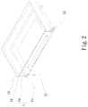
- FIG. 2is an cutaway view of the jig structure of FIG. 1 ;
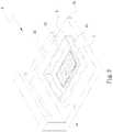
- FIG. 3shows the jig structure for manufacturing heat dissipation unit according to the present invention is positioned on a worktable of a laser machining tool for use.
- FIGS. 1 and 2are exploded perspective view and cutaway view, respectively, of a jig structure for manufacturing heat dissipation unit according to a preferred embodiment of the present invention.
- the jig structure according to the preferred embodiment of the present inventionincludes a main body 1 .
- the main body 1internally defines a chamber 11 and has a top 12 forming an upper side thereof.
- the top 12defines at least one opening 13 , on which at least one silicon dioxide layer 14 is provided.
- the chamber 11is in a vacuum-tight state; and the main body 1 can be made of an aluminum material or a stainless steel material.
- the main body 1is formed of a first part 1 a and a second part 1 b , which are correspondingly assembled together to define the chamber 11 in between them.
- the top 12is located on one side of the first part 1 a .
- the main body 1is provided with at least one passage 15 communicable with the chamber 11 , so that the chamber 11 can be vacuumized or an inert gas can be supplied into the chamber 11 via the passage 15 .
- the silicon dioxide layer 14is quartz and has average 92% transmittance of light within the range of 260 nm and 1100 nm.
- An anti-reflection film 141can be further provided on each of two opposite surfaces of the silicon dioxide layer 14 ; and the silicon dioxide layer 14 with the anti-reflection films 141 can have 98% to 100% transmittance of light within the range of 400 nm and 1100 nm to thereby increase its transmittance of laser.
- FIG. 3shows the use of the jig structure for manufacturing heat dissipation unit according to the present invention.
- the jig structure for manufacturing heat dissipation unitis also briefly referred to as the jig structure and generally denoted by reference numeral 2 .
- a laser welding processis to be performed on a workpiece 4 , which is a heat dissipation unit according to the present invention, first position the jig structure 2 on a worktable 31 of a laser machining tool 3 , and then position the workpiece 4 in the jig structure 2 .
- the jig structure 2 for manufacturing heat dissipation unitis then tightly closed, and the chamber 11 of the jig structure 2 can be vacuumized or an inert gas, such as argon, is supplied into the chamber 11 of the jig structure 2 via the at least one passage 15 , in order to protect the workpiece 4 against contamination and prevent the occurrence of oxidation reaction.
- a laser beam 33exits from the laser head 32 to penetrate the silicon dioxide layer 14 on the top 12 of the main body 1 into the jig structure 2 to conduct laser machining or laser welding on the workpiece 4 .
- the silicon dioxide layer 14 used in the present inventionis quartz that has at least 92% transmittance of laser beam 33 , the laser machining and laser welding performed can have relatively lowered power loss, while a vacuum-tight or an inert-gas-protected working environment can be maintained.
- the jig structure for manufacturing heat dissipation unit according to the present inventionenables increased flexibility in performing laser machining or laser welding and can be advantageously provided in different sizes according to the size of the workpiece, i.e. the heat dissipation unit to be manufactured, which in turn enables lowered manufacturing cost.
Landscapes
- Engineering & Computer Science (AREA)
- Physics & Mathematics (AREA)
- Mechanical Engineering (AREA)
- Optics & Photonics (AREA)
- Plasma & Fusion (AREA)
- Thermal Sciences (AREA)
- General Engineering & Computer Science (AREA)
- Life Sciences & Earth Sciences (AREA)
- Sustainable Development (AREA)
- Laser Beam Processing (AREA)
Abstract
Description
Claims (6)
Priority Applications (1)
| Application Number | Priority Date | Filing Date | Title |
|---|---|---|---|
| US16/041,829US11033989B2 (en) | 2018-07-22 | 2018-07-22 | Jig structure for manufacturing heat dissipation unit |
Applications Claiming Priority (1)
| Application Number | Priority Date | Filing Date | Title |
|---|---|---|---|
| US16/041,829US11033989B2 (en) | 2018-07-22 | 2018-07-22 | Jig structure for manufacturing heat dissipation unit |
Publications (2)
| Publication Number | Publication Date |
|---|---|
| US20200023475A1 US20200023475A1 (en) | 2020-01-23 |
| US11033989B2true US11033989B2 (en) | 2021-06-15 |
Family
ID=69162267
Family Applications (1)
| Application Number | Title | Priority Date | Filing Date |
|---|---|---|---|
| US16/041,829Active2039-03-18US11033989B2 (en) | 2018-07-22 | 2018-07-22 | Jig structure for manufacturing heat dissipation unit |
Country Status (1)
| Country | Link |
|---|---|
| US (1) | US11033989B2 (en) |
Families Citing this family (3)
| Publication number | Priority date | Publication date | Assignee | Title |
|---|---|---|---|---|
| CN112518096A (en)* | 2020-11-17 | 2021-03-19 | 西安飞机工业(集团)有限责任公司 | Device and method for welding ultrahigh-strength steel after preheating by using vacuum electron beams |
| CN112264705A (en)* | 2020-11-30 | 2021-01-26 | 北京精密机电控制设备研究所 | Be used for medical titanium alloy material impeller laser welding frock |
| CN115338499B (en)* | 2022-07-21 | 2024-03-08 | 深圳兴奇宏科技有限公司 | Manufacturing method of heat dissipating device |
Citations (9)
| Publication number | Priority date | Publication date | Assignee | Title |
|---|---|---|---|---|
| TW200740492A (en) | 2006-04-28 | 2007-11-01 | Ota Precision Ind Co Ltd | A producing method for golf club head using laser to welding different materials |
| TW200808480A (en) | 2006-08-04 | 2008-02-16 | Foxsemicon Integrated Tech Inc | Laser cutting apparatus and method |
| CN201082499Y (en) | 2007-09-30 | 2008-07-09 | 荀建华 | Crystalline silicon solar cell string welding template |
| US20090200278A1 (en) | 2005-04-21 | 2009-08-13 | Amesbury Marjan S | Laser welding system |
| US7695774B2 (en)* | 2002-01-31 | 2010-04-13 | Fuji Xerox Co., Ltd. | Titanium oxide photocatalyst thin film and production method of titanium oxide photocatalyst thin film |
| CN106141452A (en) | 2016-08-11 | 2016-11-23 | 东莞市金运汇研激光科技有限公司 | A kind of adhesive sticker packaging material laser die cutting device |
| US20170120332A1 (en)* | 2015-10-30 | 2017-05-04 | Seurat Technologies, Inc. | Additive Manufacturing System And Method |
| CN108213708A (en) | 2018-03-06 | 2018-06-29 | 深圳众为激光设备有限公司 | New fuel cell ultra-thin metal bipolar plate laser soldering device and its installation method |
| US20180246089A1 (en)* | 2015-09-14 | 2018-08-30 | Essenlix Corporation | Device and system for analyzing a sample, particularly blood, as well as methods of using the same |
- 2018
- 2018-07-22USUS16/041,829patent/US11033989B2/enactiveActive
Patent Citations (9)
| Publication number | Priority date | Publication date | Assignee | Title |
|---|---|---|---|---|
| US7695774B2 (en)* | 2002-01-31 | 2010-04-13 | Fuji Xerox Co., Ltd. | Titanium oxide photocatalyst thin film and production method of titanium oxide photocatalyst thin film |
| US20090200278A1 (en) | 2005-04-21 | 2009-08-13 | Amesbury Marjan S | Laser welding system |
| TW200740492A (en) | 2006-04-28 | 2007-11-01 | Ota Precision Ind Co Ltd | A producing method for golf club head using laser to welding different materials |
| TW200808480A (en) | 2006-08-04 | 2008-02-16 | Foxsemicon Integrated Tech Inc | Laser cutting apparatus and method |
| CN201082499Y (en) | 2007-09-30 | 2008-07-09 | 荀建华 | Crystalline silicon solar cell string welding template |
| US20180246089A1 (en)* | 2015-09-14 | 2018-08-30 | Essenlix Corporation | Device and system for analyzing a sample, particularly blood, as well as methods of using the same |
| US20170120332A1 (en)* | 2015-10-30 | 2017-05-04 | Seurat Technologies, Inc. | Additive Manufacturing System And Method |
| CN106141452A (en) | 2016-08-11 | 2016-11-23 | 东莞市金运汇研激光科技有限公司 | A kind of adhesive sticker packaging material laser die cutting device |
| CN108213708A (en) | 2018-03-06 | 2018-06-29 | 深圳众为激光设备有限公司 | New fuel cell ultra-thin metal bipolar plate laser soldering device and its installation method |
Also Published As
| Publication number | Publication date |
|---|---|
| US20200023475A1 (en) | 2020-01-23 |
Similar Documents
| Publication | Publication Date | Title |
|---|---|---|
| US11033989B2 (en) | Jig structure for manufacturing heat dissipation unit | |
| CN110773866B (en) | Vacuum welding device and method for amorphous alloy | |
| US6464129B2 (en) | Method of diffusion bonding superalloy components | |
| US11029097B2 (en) | Heat dissipation component | |
| CN101733552A (en) | Laser welding device | |
| CN108515263B (en) | A kind of laser welding method of explosion-proof disc for aluminum shell battery cover | |
| CN108714746B (en) | Heat dissipation unit fixture structure | |
| TW201836092A (en) | Vapor chamber | |
| JP4740132B2 (en) | Window equipment | |
| US9352412B2 (en) | Method of forming a bonded assembly | |
| JP2017131904A (en) | Atmosphere control laser processing head and atmosphere control laser processing method | |
| JP3399596B2 (en) | Method and apparatus for diffusion bonding | |
| US9027823B2 (en) | Workpiece arrangement | |
| JP5593324B2 (en) | Electron beam welding of large vacuum chamber bodies with high emissivity coating materials | |
| CN208427870U (en) | Heat dissipation unit fixture structure | |
| US20200023422A1 (en) | Heat dissipation component manufacturing method | |
| US20200025461A1 (en) | Method of manufacturing heat dissipation unit | |
| JPH0768397A (en) | Method for decompression laser beam machining | |
| TWI665954B (en) | Heat sink unit fixture structure | |
| CN108716871B (en) | Heat dissipating element and manufacturing method thereof | |
| TW201516366A (en) | Chamber for heat treatment device and heat treatment device | |
| TWM568027U (en) | Jig structure of heat-dissipation unit | |
| CN108907460A (en) | Thermal unit manufacturing method | |
| JP2024139767A (en) | Method for manufacturing a structure with a cavity - Patents.com | |
| JP2006073977A (en) | Method for manufacturing wafer level package using laser irradiation |
Legal Events
| Date | Code | Title | Description |
|---|---|---|---|
| AS | Assignment | Owner name:ASIA VITAL COMPONENTS CO., LTD., TAIWAN Free format text:ASSIGNMENT OF ASSIGNORS INTEREST;ASSIGNOR:LIN, CHIH-YEH;REEL/FRAME:046602/0323 Effective date:20180709 | |
| FEPP | Fee payment procedure | Free format text:ENTITY STATUS SET TO UNDISCOUNTED (ORIGINAL EVENT CODE: BIG.); ENTITY STATUS OF PATENT OWNER: LARGE ENTITY | |
| STPP | Information on status: patent application and granting procedure in general | Free format text:NON FINAL ACTION MAILED | |
| STPP | Information on status: patent application and granting procedure in general | Free format text:RESPONSE TO NON-FINAL OFFICE ACTION ENTERED AND FORWARDED TO EXAMINER | |
| STPP | Information on status: patent application and granting procedure in general | Free format text:NOTICE OF ALLOWANCE MAILED -- APPLICATION RECEIVED IN OFFICE OF PUBLICATIONS | |
| STPP | Information on status: patent application and granting procedure in general | Free format text:PUBLICATIONS -- ISSUE FEE PAYMENT RECEIVED | |
| STPP | Information on status: patent application and granting procedure in general | Free format text:PUBLICATIONS -- ISSUE FEE PAYMENT VERIFIED | |
| STPP | Information on status: patent application and granting procedure in general | Free format text:AWAITING TC RESP, ISSUE FEE PAYMENT VERIFIED | |
| STPP | Information on status: patent application and granting procedure in general | Free format text:PUBLICATIONS -- ISSUE FEE PAYMENT VERIFIED | |
| STCF | Information on status: patent grant | Free format text:PATENTED CASE | |
| MAFP | Maintenance fee payment | Free format text:PAYMENT OF MAINTENANCE FEE, 4TH YEAR, LARGE ENTITY (ORIGINAL EVENT CODE: M1551); ENTITY STATUS OF PATENT OWNER: LARGE ENTITY Year of fee payment:4 |