US11033752B2 - Photobiomodulation therapy systems and methods - Google Patents
Photobiomodulation therapy systems and methodsDownload PDFInfo
- Publication number
- US11033752B2 US11033752B2US16/167,385US201816167385AUS11033752B2US 11033752 B2US11033752 B2US 11033752B2US 201816167385 AUS201816167385 AUS 201816167385AUS 11033752 B2US11033752 B2US 11033752B2
- Authority
- US
- United States
- Prior art keywords
- rigid housing
- light
- bracket
- width
- light device
- Prior art date
- Legal status (The legal status is an assumption and is not a legal conclusion. Google has not performed a legal analysis and makes no representation as to the accuracy of the status listed.)
- Active
Links
Images


Classifications
- A—HUMAN NECESSITIES
- A61—MEDICAL OR VETERINARY SCIENCE; HYGIENE
- A61N—ELECTROTHERAPY; MAGNETOTHERAPY; RADIATION THERAPY; ULTRASOUND THERAPY
- A61N5/00—Radiation therapy
- A61N5/06—Radiation therapy using light
- A61N5/0613—Apparatus adapted for a specific treatment
- A61N5/0616—Skin treatment other than tanning
- A—HUMAN NECESSITIES
- A61—MEDICAL OR VETERINARY SCIENCE; HYGIENE
- A61N—ELECTROTHERAPY; MAGNETOTHERAPY; RADIATION THERAPY; ULTRASOUND THERAPY
- A61N5/00—Radiation therapy
- A61N5/06—Radiation therapy using light
- A61N2005/0632—Constructional aspects of the apparatus
- A61N2005/0633—Arrangements for lifting or hinging the frame which supports the light sources
- A—HUMAN NECESSITIES
- A61—MEDICAL OR VETERINARY SCIENCE; HYGIENE
- A61N—ELECTROTHERAPY; MAGNETOTHERAPY; RADIATION THERAPY; ULTRASOUND THERAPY
- A61N5/00—Radiation therapy
- A61N5/06—Radiation therapy using light
- A61N2005/0635—Radiation therapy using light characterised by the body area to be irradiated
- A61N2005/0636—Irradiating the whole body
- A61N2005/064—Irradiating the whole body in a vertical position
- A—HUMAN NECESSITIES
- A61—MEDICAL OR VETERINARY SCIENCE; HYGIENE
- A61N—ELECTROTHERAPY; MAGNETOTHERAPY; RADIATION THERAPY; ULTRASOUND THERAPY
- A61N5/00—Radiation therapy
- A61N5/06—Radiation therapy using light
- A61N2005/0635—Radiation therapy using light characterised by the body area to be irradiated
- A61N2005/0643—Applicators, probes irradiating specific body areas in close proximity
- A61N2005/0645—Applicators worn by the patient
- A—HUMAN NECESSITIES
- A61—MEDICAL OR VETERINARY SCIENCE; HYGIENE
- A61N—ELECTROTHERAPY; MAGNETOTHERAPY; RADIATION THERAPY; ULTRASOUND THERAPY
- A61N5/00—Radiation therapy
- A61N5/06—Radiation therapy using light
- A61N2005/065—Light sources therefor
- A61N2005/0651—Diodes
- A—HUMAN NECESSITIES
- A61—MEDICAL OR VETERINARY SCIENCE; HYGIENE
- A61N—ELECTROTHERAPY; MAGNETOTHERAPY; RADIATION THERAPY; ULTRASOUND THERAPY
- A61N5/00—Radiation therapy
- A61N5/06—Radiation therapy using light
- A61N2005/065—Light sources therefor
- A61N2005/0651—Diodes
- A61N2005/0652—Arrays of diodes
- A—HUMAN NECESSITIES
- A61—MEDICAL OR VETERINARY SCIENCE; HYGIENE
- A61N—ELECTROTHERAPY; MAGNETOTHERAPY; RADIATION THERAPY; ULTRASOUND THERAPY
- A61N5/00—Radiation therapy
- A61N5/06—Radiation therapy using light
- A61N2005/0658—Radiation therapy using light characterised by the wavelength of light used
- A61N2005/0659—Radiation therapy using light characterised by the wavelength of light used infrared
- A—HUMAN NECESSITIES
- A61—MEDICAL OR VETERINARY SCIENCE; HYGIENE
- A61N—ELECTROTHERAPY; MAGNETOTHERAPY; RADIATION THERAPY; ULTRASOUND THERAPY
- A61N5/00—Radiation therapy
- A61N5/06—Radiation therapy using light
- A61N2005/0658—Radiation therapy using light characterised by the wavelength of light used
- A61N2005/0662—Visible light
- A61N2005/0663—Coloured light
Definitions
- Various embodiments disclosed hereinrelate to photobiomodulation therapy systems and methods.
- Photobiomodulation therapyis a therapeutic technique that uses low-level wavelengths of light to improve health and treat a variety of health conditions, including skin issues, such as wrinkles, scars, and persistent wounds, among many other conditions. Similar to how plants use sunlight to heal and grow, humans and animals are able to harness these wavelengths of light and turn them into cellular energy. This treatment stimulates the body's natural healing processes.
- the disclosureincludes a variety of embodiments whereby two or more light devices are electrically and/or mechanically coupled together to form a modular photobiomodulation therapy system.
- photobiomodulationshall be used interchangeably with the term “light”.
- photobiomodulation and lightshall include wavelengths of light in the red, blue, green, and near infrared spectrums.
- the photobiomodulation therapy systemincludes a first light device and a second light device arranged and configured to be coupled to the first light device.
- the first light devicemay include a first housing and a first plurality of lights arranged and configured to emit at least one of red light, blue light, green light, and/or near infrared light.
- the second light devicemay include a second housing and a second plurality of lights arranged and configured to emit at least one of red light, blue light, green light, and/or near infrared light.
- the first light deviceis arranged and configured to be electrically coupled to the second light device.
- the first light devicecomprises a first power management system electrically coupled to the first plurality of lights
- the second light devicecomprises a second power management system electrically coupled to the second plurality of lights.
- Embodimentsmay thereby include a first power cord arranged and configured to be electrically coupled to the first power management system and a first power outlet. Additionally, embodiments may include a second power cord arranged and configured to be electrically coupled to the first power management system and the second power management system. This may allow the first light device and the second light device to be electrically paired together in series.
- the photobiomodulation therapy systemcan be expanded by adding a third light device arranged and configured to be coupled to at least one of the first light device and the second light device, and a fourth light device arranged and configured to be coupled to at least one of the first light device, second light device, and third light device.
- the third light devicemay include a third housing, a third plurality of lights arranged and configured to emit at least one of red light, blue light, green light, and/or near infrared light, and a third power management system electrically coupled to the third plurality of lights.
- the fourth light devicemay include a fourth housing, a fourth plurality of lights arranged and configured to emit at least one of red light, blue light, green light, and/or near infrared light, and a fourth power management system electrically coupled to the fourth plurality of lights.
- Embodimentsmay thereby include a third power cord arranged and configured to be electrically coupled to the third power management system and a second power outlet.
- embodimentsmay include a fourth power cord arranged and configured to be electrically coupled to the third power management system and the fourth power management system. This may allow the third light device and the fourth light device to be electrically coupled in series, and these together are in parallel with the first light device and the second light device.
- Embodimentsmay also include a third power cord that can be arranged and configured to be electrically coupled to the second power management system and a third power management system. Additionally, embodiments may include a fourth power cord that may also be arranged and configured to be electrically coupled to the third power management system and the fourth power management system. This may allow the first light device, second light device, third light device, and fourth light device to all be electrically coupled in series.
- the photobiomodulation therapy systemcan further be expanded to include a fifth light device arranged and configured to be coupled to at least one of the first light device, second light device, third light device, and fourth light device, and a sixth light device arranged and configured to be coupled to at least one of the first light device, second light device, third light device, fourth light device, and fifth light device.
- the fifth light devicemay include a fifth housing, a fifth plurality of lights arranged and configured to emit at least one of red light, blue light, green light, and/or near infrared light, and a fifth power management system electrically coupled to the fifth plurality of lights.
- the sixth light devicemay include a sixth housing, a sixth plurality of lights arranged and configured to emit at least one of red light, blue light, green light, and/or near infrared light, and a sixth power management system electrically coupled to the sixth plurality of lights.
- a sixth power management systemelectrically coupled to the sixth plurality of lights.
- Such embodimentsmay thereby include a fourth power cord electrically coupled to the second power outlet.
- embodimentsmay include a fifth power cord arranged and configured to be electrically coupled to the fourth power management system and the fifth power management system, and a sixth power cord arranged and configured to be electrically coupled to the fifth power management system and the sixth power management system. This may allow the fourth light device, fifth light device, and sixth light device to be electrically coupled in series, and paired together in parallel with the first, second, and third light devices.
- embodimentsmay be configured whereby all of the light devices are coupled together in series.
- embodimentsmay thereby include the fourth power cord arranged and configured to be electrically coupled to the third power management system and the fourth power management system.
- embodimentsmay include a fifth power cord arranged and configured to be electrically coupled to the fourth power management system and a fifth power management system, and a sixth power cord arranged and configured to be electrically coupled to the fifth power management system and the sixth power management system.
- thismay allow the first light device, second light device, third light device, fourth light device, fifth light device, and sixth light device to all be electrically coupled in series.
- two or more light devicesmay be mechanically coupled together to form a variety of sizes and configurations.
- the systemincludes a first aperture located on a bottom side of the first housing, and a second aperture located on the bottom side of the first housing.
- embodimentsmay include a first attachment member extending from a top surface of the second housing.
- the first attachment membermay be arranged and configured to be detachably coupled to the first aperture to thereby couple the first housing to the second housing.
- embodimentsmay include a second attachment member extending from the top surface of the second housing.
- the second attachment membermay be arranged and configured to be detachably coupled to the second aperture to thereby couple the first housing to the second housing. Mechanically coupling the first light device and the second light device in this way achieves a top-to-bottom orientation.
- some embodimentsmay be mechanically coupled in a side-by-side orientation.
- the systemincludes a first bracket arranged and configured to be detachably coupled to a back side of the first housing and a back side of the second housing to thereby detachably couple the first housing to the second housing.
- some embodimentsinclude a second bracket arranged and configured to be detachably coupled to the back side of the first housing and the back side of the second housing to detachably couple the first housing to the second housing.
- the systemincludes a door stand to thereby mount the light therapy system to a door.
- some embodimentsinclude a first attachment member extending from a top surface of the first housing.
- the first attachment membermay be arranged and configured to be detachably coupled to a first door stand.
- some embodimentsinclude a second attachment member extending from the top surface of the first housing.
- the second attachment membermay be arranged and configured to be detachably coupled to the first door stand.
- some embodimentsinclude a third attachment member extending from a top surface of the second housing.
- the third attachment membermay be arranged and configured to be detachably coupled to a second door stand.
- some embodimentsinclude a fourth attachment member extending from the top surface of the second housing. Likewise, the fourth attachment member may be arranged and configured to be detachably coupled to the second door stand.
- the light therapy systemcan be expanded by adding a third light device arranged and configured to be detachably coupled to at least one of the first light device and the second light device, and a fourth light device arranged and configured to be detachably coupled to at least one of the first light device, second light device, and third light device.
- the third light devicemay include a third housing and a third plurality of lights arranged and configured to emit at least one of red light, blue light, green light, and/or near infrared light.
- the fourth light devicemay include a fourth housing and a fourth plurality of lights arranged and configured to emit at least one of red light, blue light, green light, and/or near infrared light.
- Some embodimentsinclude a third bracket arranged and configured to be detachably coupled to a back side of the third housing and a back side of the fourth housing to thereby detachably couple the third housing to the fourth housing. Additionally, some embodiments include a fourth bracket arranged and configured to be detachably coupled to the back side of the third housing and the back side of the fourth housing to thereby detachably couple the third housing to the fourth housing.
- the systemincludes a first aperture and a second aperture both located on a bottom side of the first housing, and a third aperture and a fourth aperture both located on a bottom side of the second housing.
- Some embodimentsmay thereby include a fifth attachment member extending from a top surface of the third housing.
- the fifth attachment membermay be arranged and configured to be detachably coupled to the first aperture.
- some embodimentsinclude a sixth attachment member extending from the top surface of the third housing.
- the sixth attachment membermay be arranged and configured to be detachably coupled to the second aperture.
- Some embodimentsmay also include a seventh attachment member extending from a top surface of the fourth housing.
- the seventh attachment membermay be arranged and configured to be detachably coupled to the third aperture.
- some embodimentsmay include an eighth attachment member extending from the top surface of the fourth housing.
- the eighth attachment membermay be arranged and configured to be detachably coupled to the fourth aperture.
- the first housing and the second housingmay include a top side, a bottom side, a front side, and a back side.
- the systemmay further include a third light device arranged and configured to be detachably coupled to at least one of the first light device and the second light device, and a fourth light device arranged and configured to be detachably coupled to at least one of the first light device, the second light device, and the third light device.
- the third light deviceincludes a third housing and a third plurality of lights arranged and configured to emit at least one of red light, blue light, green light, and/or near infrared light.
- the fourth light deviceincludes a fourth housing and a fourth plurality of lights arranged and configured to emit at least one of red light, blue light, green light, and/or near infrared light.
- some embodimentsinclude a first bracket arranged and configured to be detachably coupled to a back side of the first housing and a back side of the second housing to thereby detachably couple the first housing to the second housing.
- some embodimentsinclude a second bracket arranged and configured to be detachably coupled to a back side of the third housing and a back side of the fourth housing to thereby detachably couple the third housing to the fourth housing.
- Some embodimentsinclude a quad bracket arranged and configured to be detachably coupled to the back side of the first housing, the back side of the second housing, the back side of the third housing, and the back side of the fourth housing to thereby detachably couple the first housing, second housing, third housing, and fourth housing together.
- the quad bracketmay be arranged and configured to be detachably coupled to a mobile stand.
- the first housing and the second housingmay include a top side, a bottom side, a front side, and a back side.
- the systemmay further include a third light device arranged and configured to be detachably coupled to at least one of the first light device and the second light device, a fourth light device arranged and configured to be detachably coupled to at least one of the first light device, the second light device, and the third light device, a fifth light device arranged and configured to be detachably coupled to at least one of the first light device, the second light device, the third light device, and the fourth light device, and a sixth light device arranged and configured to be detachably coupled to at least one of the first light device, the second light device, the third light device, the fourth light device, and the fifth light device.
- the third light deviceincludes a third housing and a third plurality of lights arranged and configured to emit at least one of red light, blue light, green light, and/or near infrared light.
- the fourth light deviceincludes a fourth housing and a fourth plurality of lights arranged and configured to emit at least one of red light, blue light, green light, and/or near infrared light.
- the fifth light deviceincludes a fifth housing and a fifth plurality of lights arranged and configured to emit at least one of red light, blue light, green light, and/or near infrared light.
- some embodimentsinclude the sixth light device, which includes a sixth housing and a sixth plurality of lights arranged and configured to emit at least one of red light, blue light, green light, and/or near infrared light. Additionally, some embodiments include a first bracket arranged and configured to be detachably coupled to a back side of the first housing, a back side of the second housing, and a back side of the fifth housing to thereby detachably couple the first light device, second light device, and fifth light device together.
- some embodimentsinclude a second bracket arranged and configured to be detachably coupled to a back side of the third housing, a back side of the fourth housing, and a back side of the sixth housing to thereby detachably couple the third light device, fourth light device, and sixth light device together.
- some embodimentsinclude a large bracket arranged and configured to be detachably coupled to the back side of the first housing, the back side of the second housing, the back side of the third housing, the back side of the fourth housing, the back side of the fifth housing, and the back side of the sixth housing to thereby detachably couple the first light device, second light device, third light device, fourth light device, fifth light device, and sixth light device together.
- the large bracketis arranged and configured to be detachably coupled to a mobile stand.
- the systemfurther includes the mobile stand having at least one vertical arm arranged and configured to couple to the large bracket. Additionally, in some embodiments, the mobile stand includes at least one horizontal leg arranged and configured to contact a floor surface.
- the first light deviceis a first modular light device and the second light device is a second modular light device whereby each of the first and second modular light devices are arranged and configured to be mechanically coupled in at least one of a side-by-side orientation and a top-to-bottom orientation.
- the systemincludes a third modular light device and a fourth modular light device each arranged and configured to be mechanically coupled to at least one of the first, second, third, and fourth modular light devices in at least one of a side-by-side orientation and a top-to-bottom orientation.
- FIG. 1illustrates a perspective view of an embodiment of a light therapy system.
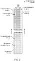
- FIG. 2illustrates a perspective view of a light therapy system, specifically how a first housing mechanically couples with a second housing.
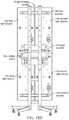
- FIG. 3illustrates a back view of a light therapy system, specifically how a first light device electrically couples with a second light device.
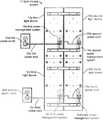
- FIG. 4illustrates a perspective view of a light therapy system having four light devices mechanically coupled.
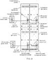
- FIG. 5illustrates a back view of a light therapy system in which a first light device is electrically coupled to a first power outlet and a second light device, and a third light device electrically coupled to a second power outlet and a fourth light device.
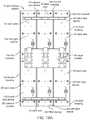
- FIG. 6illustrates a back view of a light therapy system in which a first light device is electrically coupled to a first power outlet and a second light device, the second light device is also electrically coupled to a third light device, and the third light device is also electrically coupled to a fourth light device.
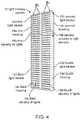
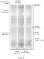
- FIG. 7illustrates a perspective view of a light therapy system having six light devices mechanically coupled together.
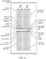
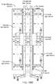
- FIG. 8illustrates a back view of a light therapy system, specifically showing six light devices mechanically and electrically coupled together.
- FIG. 9illustrates a back view of another light therapy system, specifically showing six light devices mechanically and electrically coupled together.
- FIG. 10illustrates a perspective view of a light therapy system in which a first light device is mechanically coupled with a second light device in a top-to-bottom orientation.
- FIG. 11illustrates a back view of a light therapy system in which a first light device is mechanically coupled to a second light device in a side-by-side orientation.
- FIG. 12illustrates a front view of a light therapy system that has four light devices mechanically coupled and is mounted to a door via a first and a second door stand.
- FIG. 13illustrates a back view of a light therapy system in which a first light device is mechanically coupled to a second light device via a first and a second bracket, and a third light device is mechanically coupled to a fourth light device via a third and a fourth bracket.
- FIG. 14illustrates a perspective view of a light therapy system mounted to a door, specifically showing a third and fourth housing mechanically coupled with a first and second housing.
- FIG. 15Aillustrates a back view of a light therapy system in which first, second, third, and fourth light devices are mechanically coupled via a first bracket, a second bracket, and a quad bracket.
- FIG. 15Billustrates a back view of a light therapy system in which first, second, third, and fourth light devices are mechanically coupled via a first bracket, a second bracket, and a quad bracket, whereby the quad bracket is mechanically coupled with a mobile stand.
- FIG. 15Cillustrates a perspective view of a mobile stand.
- FIG. 16illustrates a perspective view of one possible embodiment of a light therapy system mounted to a mobile stand that is capable of rotation on two axes.
- FIG. 17illustrates a perspective view of a light therapy system mounted to a mobile stand in which a first and second light device have a first form factor, and a third and fourth light device have a second form factor.
- FIG. 18Aillustrates a back view of a light therapy system in which first, second, third, fourth, fifth, and sixth light devices are mechanically coupled via a first bracket, a second bracket, and a large bracket.
- FIG. 18Billustrates a back view of a light therapy system in which first, second, third, fourth, fifth, and sixth light devices are mechanically coupled via a first bracket, a second bracket, and a large bracket that is mechanically coupled with a mobile stand.
- FIG. 19illustrates a perspective view of a light therapy system that includes a mini stand.
- FIG. 20illustrates a perspective view of a light therapy system that includes a wall mount for attaching the system to a substrate, such as a wall.
- Photobiomodulation therapyprovides an alternative option for treating many common ailments and diseases. For example, when the human body is exposed to red light, blue light, green light, and/or near infrared light, subjects can expect to see improvement in multiple skin conditions, weight loss, muscle recovery, sexual performance, joint pain, and thyroid function. Instead of using prescription medications to solve these many problems, light therapy can be used in place of these traditional remedies to achieve safe and effective results.
- Light therapyhas been adopted by many top professionals, but oftentimes the light therapy devices and systems used are not big enough to treat an entire body at once. Accordingly, many embodiments described herein enable two or more light therapy devices to be coupled together in various ways. In doing so, the area of treatment can be expanded to reduce the time and number of treatments to achieve the desired results.
- the disclosureincludes a light therapy system 10 that includes two or more light devices 12 .
- the system 10includes four light devices, such as a first light device 12 a , a second light device 12 b , a third light device 12 c , and a fourth light device 12 d .
- the four light devices 12may be electrically and mechanically coupled together.
- the light therapy system 10may further include an auxiliary mounting device, such as a mobile stand and/or a door stand, to assist in transporting and positioning the system 10 .
- the system 10may include a first light device 12 a comprising a first housing 14 a and a first plurality of lights 16 a , and a second light device 12 b comprising a second housing 14 b and a second plurality of lights 16 b .
- the second light device 12 bmay be arranged and configured to couple to the first light device 12 a .
- Both the first plurality of lights 16 a and the second plurality of lights 16 bare arranged and configured to emit red light, blue light, green light, and/or near infrared light.
- the plurality of lights 16 a and 16 bmay comprise a plurality of light emitting diodes (LED).
- LEDsare specifically mentioned herein, any light source capable of emitting red light, blue light, green light, and/or near infrared light may be appropriate.
- each light of the plurality of lightsmay be configured to emit both red light, blue light, green light, and/or near infrared light, or each light may be configured to only emit red light, blue light, green light, and/or near infrared light.
- the first light device 12 ais arranged and configured to electrically couple to the second light device 12 b .
- FIG. 3illustrates one embodiment of how this may be achieved.
- the first light device 12 amay comprise a first power management system 18 a , which is electrically coupled to the first plurality of lights 16 a .
- the second light device 12 bmay comprise a second power management system 18 b , which is electrically coupled to the second plurality of lights 16 b .
- the power management systems 18may include an input port configured to receive a cord to thereby transfer power into the light devices 12 , and an output port configured to transfer power out of the light device 12 .
- FIG. 3further illustrates an embodiment which has a first power cord 20 a electrically coupled to the first power management system 18 a and a first power outlet 22 a . Furthermore, FIG. 3 illustrates a second power cord 20 b electrically coupled to the second power management system 18 b . In such embodiments, power may pass through the first light device 12 a via the second power cord 20 b such that the second light device 12 b will have sufficient power to perform as expected.
- the power cord(s) 20may also be configured to send signals from one light device 12 to another. This can be advantageous to ensure that multiple light devices 12 perform the same task. For example, a user may wish to use only red light, blue light, green light, and/or near infrared light, or any combination of lights.
- a usermay input instructions into the first light device 12 a , and the signal will be carried through by the second power cord 20 b to the second light device 12 b .
- the second light device 12 bwill be paired to the first light device 12 a.
- FIG. 4illustrates a perspective view of an embodiment which comprises, in addition to the first light device 12 a and the second light device 12 b , a third light device 12 c configured to be electrically coupled with the first light device 12 a and/or the second device 12 b .
- the third light device 12 cmay comprise a third housing 14 c , a third plurality of lights 16 c , and a third power management system 18 c ( FIG. 5 ).
- the embodiment depicted in FIG. 4also shows a fourth light device 12 d configured to be coupled with any one of the first light device 12 a , second light device 12 b , and/or the third light device 12 c .
- the fourth light device 12 dmay also comprise a fourth housing 14 d , a fourth plurality of lights 16 d , and a fourth power management system 18 d ( FIG. 5 ).
- the third plurality of lights 16 c and the fourth plurality of lights 16 dmay also be configured to emit red light, blue light, green light, and/or near infrared light.
- the light therapy system 10may be arranged in a variety of electrical configurations, whereby light devices 12 are electrically coupled in series.
- FIGS. 5, 6, 8, and 9illustrate two different scenarios of how the system 10 may be coupled.
- the system 10may be electrically coupled in series having a maximum number of three light devices 12 per series. In other words, three light devices may be electrically coupled in series to a power outlet 22 . Because there are four light devices 12 in FIG. 5 , the configuration thereby requires two power outlets 22 a and 22 b .
- a third power cord 20 cmay be electrically coupled to a third power management system 18 c and a second power outlet 22 b .
- a fourth power cord 20 dmay be electrically coupled to the third power management system 18 c and a fourth power management system 18 d .
- the second and fourth light devices 12 b , 12 dmay thereby receive electrical power from the first and third light devices 12 a , 12 c , respectively, which in turn receive electrical power from the first and second power outlets 22 a , 22 b , respectively.
- some embodimentsmay be configured with no limit on the number of light devices 12 electrically coupled in series.
- the third power cord 20 cmay be electrically coupled to the second power management system 18 b and the third power management system 18 c .
- the fourth power cord 28 dmay be electrically coupled to the third power management system 18 c and the fourth power management system 18 d . Coupling the third power cord 18 c in this way removes the need for the second power outlet 22 b .
- This configurationmay be advantageous depending on the power requirements of the light therapy system 10 . For example, smaller light devices may require less power to achieve the desired outcome. However, a larger light device may require a great deal more power than only one power outlet can provide.
- FIGS. 7, 8, and 9depict how some embodiments of a light therapy system 10 may be further expanded from four to six light devices and how the light devices may be electrically coupled to provide necessary power.
- a fifth light device 12 emay be coupled to the any one of the first, second, third, or fourth light devices 12 a , 12 b , 12 c , 12 d .
- the fifth light device 12 emay comprise a fifth housing 14 e , a fifth plurality of lights 16 e , and a fifth power management system 18 e .
- the fifth power management 18 e systemmay be electrically coupled with the fifth plurality of lights 16 e .
- a sixth light device 12 fmay be configured to be coupled to any one of the first, second, third, fourth, or fifth light devices 12 a , 12 b , 12 c , 12 d , 12 e .
- the sixth light device 12 fmay comprise a sixth housing 14 f , a sixth plurality of lights 16 f , and a sixth power management system 18 f .
- the sixth power management 18 f systemmay be electrically coupled with the sixth plurality of lights 16 f . It should be appreciated that the plurality of lights 16 e and 16 f are configured to emit red light, blue light, green light, and/or near infrared light.
- FIG. 8illustrates a light therapy system 10 having six light devices 12 a , 12 b , 12 c , 12 d , 12 e , and 12 f . Because the embodiment illustrated in FIG. 8 is limited to three devices in series, the system 10 thereby requires two power outlets 22 a , 22 b .
- the fourth power cord 20 dmay be electrically coupled to the fourth power management system 18 d and the second power outlet 22 b .
- a fifth power cord 20 emay be electrically coupled to the fourth power management system 18 d and the fifth power management system 18 e .
- the sixth power cord 20 fmay be electrically coupled to the fifth power management system 18 e and the sixth power management system 18 f .
- the first through third light devices 12 a , 12 b , and 12 care connected in a first series
- the fourth through sixth light devices 12 d , 12 e , and 12 fare connected in a second series.
- FIG. 9shows another embodiment in which all the light devices 12 a , 12 b , 12 c , 12 d , 12 e , and 12 f are all connected in one series.
- the fourth power cord 20 dmay be electrically coupled to the third power management system 18 c and the fourth power management system 18 d .
- the fifth power cord 20 emay be electrically coupled to the fourth power management system 18 d and the fifth power management system 18 e .
- the sixth power cord 20 fmay thereby be electrically coupled to the fifth power management system 18 e and the sixth power management system 18 f . Configuring the light therapy system 10 in this manner avoids the need for the second power outlet 22 b.
- FIG. 10illustrates an embodiment of how two light devices 12 may be configured for mechanical coupling in a top-to-bottom orientation.
- the light therapy system 10 of FIG. 10comprises a first aperture 30 a and a second aperture 30 b located on the bottom surface 32 of the first housing 14 a .
- a first attachment member 34 a and a second attachment member 34 bare located on the top surface 36 of the second housing 14 b .
- the attachment members 34may be thereby securely fit into the apertures 30 to mechanically couple the light devices 12 together.
- the attachment members 34 shown in FIG. 10are posts, but any mechanism suitable for mechanical coupling may be implemented.
- light devices 12may be mechanically coupled together via adhesive, bolts, and the like.
- the attachment members 34are detachably coupled with the apertures 30 such that a user may detach the light devices 12 from one another.
- FIG. 11depicts an embodiment of a light therapy system 10 in which two light devices 12 are mechanically coupled in a side-by-side orientation.
- the embodiment in FIG. 11shows a first bracket 38 a mechanically coupled to the back side 40 of the first and second light devices 12 a and 12 b .
- a second bracket 38 bis also mechanically coupled to the back side 40 of the first and second light devices 12 a and 12 b .
- the brackets 38are detachably coupled to the light devices 12 .
- FIG. 12shows one embodiment in which two light devices 12 a and 12 b are mechanically coupled in a side-by-side orientation and mounted to a first and a second door stand 42 a and 42 b .
- a first attachment member 39 a and a second attachment member 39 bmay extend from the top surface 36 and be detachably coupled to the first door stand 42 a .
- the second door stand 42 bis detachably coupled to the third attachment member 39 c and the fourth attachment member 39 d.
- FIGS. 13 and 14show light therapy system 10 embodiments that combine the top-to-bottom coupling with the side-by-side coupling to achieve a two by two grid of light devices 12 .
- FIG. 13illustrates a third bracket 38 c and a fourth bracket 38 d coupled to the back side 40 of the third housing 14 c and the fourth housing 14 d .
- FIG. 14illustrates a fifth attachment post 34 e , a sixth attachment post 34 f , a seventh attachment post 34 g , and an eighth attachment post 34 h coupled to the top surface 36 of the third light device 12 c and the fourth light device 12 d .
- the illustration in FIG. 14further depicts the two by two grid of light devices 12 mounted to door stands 42 .
- the four light devices 12may be mechanically coupled together in other arrangements.
- one embodimentmay have all four light devices 12 coupled together in a side-by-side orientation forming a one by four grid.
- three light devices 12may be coupled together in a side-by-side orientation and the fourth light device 12 d may be coupled to any one of the other three light devices 12 in a top-to-bottom orientation.
- Another possible embodimentmay feature a four by one grid in which the four light devices 12 are all coupled in a top-to-bottom orientation.
- any arrangement or configuration of light devicesmay be achieved using the modular concepts disclosed herein.
- the disclosurealso includes various devices for mounting the system 10 and/or light device(s) 12 .
- a standsuch as a mobile stand 50 , table top stand 59 (or mini stand 59 ), wall stand 58 , and the like.
- a standmay thereby allow the system 10 and/or device(s) 12 to be easily transported from one place to another and then quickly configured in a variety of positions to effectively apply therapy to any treatment zone on a patient.
- a standmay allow a user to set up the system 10 and/or light device 12 in an easy to access yet out of the way location, such as the wall stand 58 .
- the light therapy system 10includes a mobile stand 50 that couples to one or more brackets on the back side of the various light devices 12 .
- the first bracket 38 amay be coupled the to the back side 40 of the first housing 14 a and the second housing 14 b and the second bracket 38 b may be coupled to the back side 40 of the third housing 14 c and the fourth housing 14 d .
- a quad bracket 44may thereby be coupled to the back side 40 of the first housing 14 a , second housing 14 b , third housing 14 c , and the fourth housing 14 d .
- the mobile stand 50may be detachably coupled to the light devices 12 , the bracket(s) 38 , and/or quad bracket 44 .
- the mobile stand 50 amay include one or more horizontal legs 54 to stabilize the system 10 .
- the one or more horizontal legs 54may include casters to make it easier for a user to move the mobile stand 50 a . Casters are not necessary though, for example, wheels may be implemented instead. Even still, the horizontal legs 54 may not include casters or wheels at all, and the horizontal legs 54 may be affixed to a ground surface or not affixed and free to move with respect to the ground surface. In any case, the horizontal leg 54 may provide balance and stability to the mobile stand 50 a . To achieve this, some part of the horizontal leg 54 may contact the ground surface.
- FIG. 17shows yet another embodiment of a mobile stand 50 b .
- the mobile stand 50 bis configured such that the light devices 12 can be rotated on a first axis 60 and/or a second axis 62 .
- Being able to rotate the light devices 12 along two axes 60 , 62may allow the system 10 to be moved into any possible position to accommodate a desired treatment. For example, if a person is lying down on a flat surface, such as a bed, the light devices 12 can be aimed downwards toward the flat surface, and treatment can be applied to a user's entire front or back side.
- the light devices 12may define more than one form factor 56 .
- FIG. 16shows an embodiment in which the light therapy system 10 is made up of light devices 12 with two different form factors 56 a and 56 b .
- the first form factor 56 a in FIG. 16is shorter than the second form factor 56 b .
- Different form factors 56can be advantageous in situations when a larger treatment area is required than one light device 12 can provide, but there is a lack of space for a second equal size light device 12 .
- Another benefitis that smaller form factors 56 a cost less than a larger form factors 56 b .
- a usermay purchase a smaller light device, such as an entry level device, and then add on to the system 10 once they become familiar and comfortable with the performance of the smaller light device.
- the different form factors 56may be configured to be modular. In this way, any amount of smaller form factor 56 a light devices 12 and larger form factor 56 b light devices may be mechanically coupled together in either a side-by-side orientation or a top-to-bottom orientation. This allows the light therapy system 10 to be configured into a customizable shape and size for unique treatment areas.
- FIG. 18AAn example of a modular embodiment can be seen in FIG. 18A .
- the illustrationshows six light devices 12 a , 12 b , 12 c , 12 d , 12 e , and 12 f mechanically coupled into a two by three grid.
- Light devices 12 a , 12 b , and 12 care coupled together via the first bracket 38 a
- the light devices 12 d , 12 e , and 12 fare coupled together via the second bracket 38 b
- the large bracket 64 located in the middlemay mechanically couple all six of the light devices 12 together.
- FIG. 18Bshows an embodiment in which the large bracket 64 also serves as a mount to couple the light system 10 to a mobile stand 50 c.
- FIGS. 18A and 18Billustrate the potential for expansion of the system 10 . Accordingly, it should be appreciated that any size and shape of brackets 38 , 44 may be used to accommodate expansion beyond six light devices 12 .
- the system 10may be configured to have 8, 10, 12, 14, 16, and 24 or more light devices 12 working together as one unified light therapy system 10 .
- the disclosureincludes a mini stand 59 that allows the light therapy system and/or one or more light devices ( 12 ) to be mounted on a table top, desk, counter, and the like.
- the mini stand 59may be arranged and configured to couple to a light device 12 , such as a smaller light device 12 , or plurality of light devices 12 all of which may define smaller form factors sized and configured to sit atop a table top, etc.
- the mini stand 59may be able to pivot, raise, and/or lower in any direction with respect to the base of the mini stand 59 .
- the system 10 and/or one or more light devices 12may also be coupled to a wall mount 58 , which can be mounted to a substrate, such as a wall.
- the system 10may include one or more attachment members 39 located at the top of the respective light device(s) 12 .
- a first portion of the wall mount 58may thereby be coupled to a wall, while a second portion of the wall mount 58 may be coupled to the attachment member(s) 39 to thereby couple the system 10 and/or light device(s) 12 to the substrate or wall.
- the wall mount 58may allow the system 10 and/or light device(s) 12 to be mounted in an easy to reach location yet physically situated out of the way to thereby reduce space requirements.
- the wall mount 58may be used to mount one light device 12 or two or more light devices 12 .
- section headings and subheadings provided hereinare nonlimiting.
- the section headings and subheadingsdo not represent or limit the full scope of the embodiments described in the sections to which the headings and subheadings pertain.
- a section titled “Topic 1”may include embodiments that do not pertain to Topic 1 and embodiments described in other sections may apply to and be combined with embodiments described within the “Topic 1” section.
- routines, processes, methods, and algorithms described in the preceding sectionsmay be embodied in, and fully or partially automated by, code modules executed by one or more computers, computer processors, or machines configured to execute computer instructions.
- the code modulesmay be stored on any type of non-transitory computer-readable storage medium or tangible computer storage device, such as hard drives, solid state memory, flash memory, optical disc, and/or the like.
- the processes and algorithmsmay be implemented partially or wholly in application-specific circuitry.
- the results of the disclosed processes and process stepsmay be stored, persistently or otherwise, in any type of non-transitory computer storage such as, e.g., volatile or non-volatile storage.
- A, B, and/or Ccan be replaced with A, B, and C written in one sentence and A, B, or C written in another sentence.
- A, B, and/or Cmeans that some embodiments can include A and B, some embodiments can include A and C, some embodiments can include B and C, some embodiments can only include A, some embodiments can include only B, some embodiments can include only C, and some embodiments can include A, B, and C.
- the term “and/or”is used to avoid unnecessary redundancy.
Landscapes
- Health & Medical Sciences (AREA)
- Biomedical Technology (AREA)
- Life Sciences & Earth Sciences (AREA)
- Engineering & Computer Science (AREA)
- Nuclear Medicine, Radiotherapy & Molecular Imaging (AREA)
- Pathology (AREA)
- Biophysics (AREA)
- Radiology & Medical Imaging (AREA)
- Animal Behavior & Ethology (AREA)
- General Health & Medical Sciences (AREA)
- Public Health (AREA)
- Veterinary Medicine (AREA)
- Radiation-Therapy Devices (AREA)
Abstract
Description
Claims (20)
Priority Applications (17)
| Application Number | Priority Date | Filing Date | Title |
|---|---|---|---|
| US16/167,385US11033752B2 (en) | 2018-10-22 | 2018-10-22 | Photobiomodulation therapy systems and methods |
| US16/227,289US10478635B1 (en) | 2018-10-22 | 2018-12-20 | Photobiomodulation therapy systems and methods |
| US29/695,277USD877920S1 (en) | 2018-10-22 | 2019-06-18 | Photobiomodulation therapy device |
| US29/695,831USD877923S1 (en) | 2018-10-22 | 2019-06-21 | Combined photobiomodulation therapy device and mounting apparatus |
| US29/695,797USD892343S1 (en) | 2018-10-22 | 2019-06-21 | Photobiomodulation therapy system |
| US29/695,772USD877921S1 (en) | 2018-10-22 | 2019-06-21 | Photobiomodulation therapy device |
| US29/695,808USD892344S1 (en) | 2018-10-22 | 2019-06-21 | Photobiomodulation therapy system |
| US29/696,393USD892345S1 (en) | 2018-10-22 | 2019-06-27 | Photobiomodulation therapy system |
| AU2019365798AAU2019365798A1 (en) | 2018-10-22 | 2019-10-21 | Photobiomodulation therapy systems and methods |
| PCT/US2019/057292WO2020086494A1 (en) | 2018-10-22 | 2019-10-21 | Photobiomodulation therapy systems and methods |
| EP19877093.5AEP3870281A4 (en) | 2018-10-22 | 2019-10-21 | Photobiomodulation therapy systems and methods |
| CA3117444ACA3117444A1 (en) | 2018-10-22 | 2019-10-21 | Photobiomodulation therapy systems and methods |
| US17/027,338US11207543B2 (en) | 2018-10-22 | 2020-09-21 | Photobiomodulation therapy device accessories |
| US17/027,472US20210001141A1 (en) | 2018-10-22 | 2020-09-21 | Photobiomodulation therapy systems and devices |
| US17/236,950US20210236838A1 (en) | 2018-10-22 | 2021-04-21 | Photobiomodulation therapy systems and methods |
| US17/559,874US11458328B2 (en) | 2018-10-22 | 2021-12-22 | Photobiomodulation therapy device accessories |
| US17/950,015US12017084B2 (en) | 2018-10-22 | 2022-09-21 | Photobiomodulation therapy device accessories |
Applications Claiming Priority (1)
| Application Number | Priority Date | Filing Date | Title |
|---|---|---|---|
| US16/167,385US11033752B2 (en) | 2018-10-22 | 2018-10-22 | Photobiomodulation therapy systems and methods |
Related Child Applications (9)
| Application Number | Title | Priority Date | Filing Date |
|---|---|---|---|
| US16/227,289Continuation-In-PartUS10478635B1 (en) | 2018-10-22 | 2018-12-20 | Photobiomodulation therapy systems and methods |
| US29/695,277Continuation-In-PartUSD877920S1 (en) | 2018-10-22 | 2019-06-18 | Photobiomodulation therapy device |
| US29/695,808Continuation-In-PartUSD892344S1 (en) | 2018-10-22 | 2019-06-21 | Photobiomodulation therapy system |
| US29/695,772Continuation-In-PartUSD877921S1 (en) | 2018-10-22 | 2019-06-21 | Photobiomodulation therapy device |
| US29/695,797Continuation-In-PartUSD892343S1 (en) | 2018-10-22 | 2019-06-21 | Photobiomodulation therapy system |
| US29/695,831Continuation-In-PartUSD877923S1 (en) | 2018-10-22 | 2019-06-21 | Combined photobiomodulation therapy device and mounting apparatus |
| US29/696,393Continuation-In-PartUSD892345S1 (en) | 2018-10-22 | 2019-06-27 | Photobiomodulation therapy system |
| US17/027,338Continuation-In-PartUS11207543B2 (en) | 2018-10-22 | 2020-09-21 | Photobiomodulation therapy device accessories |
| US17/236,950Continuation-In-PartUS20210236838A1 (en) | 2018-10-22 | 2021-04-21 | Photobiomodulation therapy systems and methods |
Publications (2)
| Publication Number | Publication Date |
|---|---|
| US20200121944A1 US20200121944A1 (en) | 2020-04-23 |
| US11033752B2true US11033752B2 (en) | 2021-06-15 |
Family
ID=70281111
Family Applications (1)
| Application Number | Title | Priority Date | Filing Date |
|---|---|---|---|
| US16/167,385ActiveUS11033752B2 (en) | 2018-10-22 | 2018-10-22 | Photobiomodulation therapy systems and methods |
Country Status (5)
| Country | Link |
|---|---|
| US (1) | US11033752B2 (en) |
| EP (1) | EP3870281A4 (en) |
| AU (1) | AU2019365798A1 (en) |
| CA (1) | CA3117444A1 (en) |
| WO (1) | WO2020086494A1 (en) |
Cited By (4)
| Publication number | Priority date | Publication date | Assignee | Title |
|---|---|---|---|---|
| US11253719B2 (en) | 2018-12-20 | 2022-02-22 | Joovv, Inc. | Photobiomodulation therapy systems and methods |
| US11300254B2 (en)* | 2020-08-21 | 2022-04-12 | Shenzhen Long Sun Optoelectronics Technology Co., Ltd. | Plant lamp, control method, and control system |
| US11458328B2 (en) | 2018-10-22 | 2022-10-04 | Joovv, Inc. | Photobiomodulation therapy device accessories |
| WO2025136542A1 (en)* | 2023-12-19 | 2025-06-26 | Mark Sawyer | Light therapy device stand |
Families Citing this family (14)
| Publication number | Priority date | Publication date | Assignee | Title |
|---|---|---|---|---|
| US11033752B2 (en) | 2018-10-22 | 2021-06-15 | Joovv, Inc. | Photobiomodulation therapy systems and methods |
| US11207543B2 (en) | 2018-10-22 | 2021-12-28 | Joovv, Inc. | Photobiomodulation therapy device accessories |
| US11464997B2 (en) | 2020-07-18 | 2022-10-11 | Konrad Jarausch | Systems and methods for light generation and use thereof |
| KR20220030475A (en)* | 2020-09-02 | 2022-03-11 | 삼성디스플레이 주식회사 | Tiled display device |
| USD963873S1 (en)* | 2020-09-21 | 2022-09-13 | Joovv, Inc. | Floor stand for a photobiomodulation therapy device |
| USD1002022S1 (en)* | 2020-09-28 | 2023-10-17 | Junlong Liu | Back therapy treatments equipment |
| US11836922B2 (en) | 2021-05-19 | 2023-12-05 | Zerigo Health, Inc. | System and method for evaluating effectiveness of a skin treatment |
| US20230181923A1 (en)* | 2021-12-09 | 2023-06-15 | Zerigo Health, Inc. | Apparatus and method for treating skin lesions |
| USD1060697S1 (en)* | 2022-08-19 | 2025-02-04 | HOT Brands, LLC | Stand-up red light therapy device |
| USD1067446S1 (en)* | 2022-10-18 | 2025-03-18 | Biofrontera Pharma Gmbh | Photodynamic therapy lamp |
| USD1052103S1 (en)* | 2022-10-18 | 2024-11-19 | Biofrontera Pharma Gmbh | Photodynamic therapy lamp head |
| USD1035022S1 (en)* | 2022-10-20 | 2024-07-09 | Shenzhen Idea Light Limited | Red light therapy device |
| GB2634206A (en)* | 2023-09-26 | 2025-04-09 | L & Co Trading Ltd | Light therapy device |
| USD1082032S1 (en)* | 2025-03-13 | 2025-07-01 | Yan Yuan | Light therapy lamp |
Citations (85)
| Publication number | Priority date | Publication date | Assignee | Title |
|---|---|---|---|---|
| US4844069A (en) | 1985-07-10 | 1989-07-04 | Kei Mori | Light rays radiation device for medical treatment |
| US5645578A (en) | 1994-11-16 | 1997-07-08 | Sybaritic, Inc. | Total therapy sauna bed system |
| US5733032A (en) | 1995-08-31 | 1998-03-31 | Charles J. Bolta | Mobile light panel stand |
| US5800478A (en)* | 1996-03-07 | 1998-09-01 | Light Sciences Limited Partnership | Flexible microcircuits for internal light therapy |
| US20030009205A1 (en)* | 1997-08-25 | 2003-01-09 | Biel Merrill A. | Treatment device for topical photodynamic therapy and method of using same |
| US6626932B2 (en) | 2000-04-17 | 2003-09-30 | Photo Therapeutics Ltd | Therapeutic light source and method |
| US20030188378A1 (en) | 2002-04-04 | 2003-10-09 | Henry Brunelle | Therapeutic shower enclosure |
| US20040008523A1 (en) | 2002-07-03 | 2004-01-15 | Life Support Technologies, Inc. | Methods and apparatus for light therapy |
| US20040014199A1 (en)* | 2002-01-09 | 2004-01-22 | Jackson Streeter | Method for preserving organs for transplant |
| US20040068305A1 (en) | 2002-10-07 | 2004-04-08 | Vineet Bansal | Phototherapy system and device |
| US20040162596A1 (en) | 2002-10-07 | 2004-08-19 | Palomar Medical Technologies, Inc. | Methods and apparatus for performing photobiostimulation |
| US20040193234A1 (en)* | 2002-07-03 | 2004-09-30 | Glenn Butler | Methods and apparatus for light therapy |
| US20050075703A1 (en)* | 2001-01-22 | 2005-04-07 | Eric Larsen | Photodynamic stimulation device and methods |
| US20050085875A1 (en)* | 2003-08-19 | 2005-04-21 | Jeffrey Van Zuylen | Photon therapy method and apparatus |
| US6955684B2 (en)* | 2002-03-29 | 2005-10-18 | Savage Jr Henry C | Portable light delivery apparatus and methods |
| US20050237739A1 (en)* | 2004-04-27 | 2005-10-27 | Lee Kian S | Illumination panel with reverse mounted solid-state light generating source array |
| US20060007059A1 (en)* | 2004-07-06 | 2006-01-12 | Bell Jonathan A | Flexible display screen arrangements and applications thereof |
| US20060020308A1 (en)* | 2004-07-20 | 2006-01-26 | Muldner James S | Light therapy device heat management |
| US7033381B1 (en)* | 1991-11-20 | 2006-04-25 | Erik Larsen | Photodynamic stimulation device and method |
| US20060217789A1 (en) | 2005-03-23 | 2006-09-28 | Thomas Perez | UV irradiation chamber and method for UV light to a body |
| US20060229689A1 (en) | 2005-04-08 | 2006-10-12 | Led Technologies, Llc | LED therapy device |
| US20070068055A1 (en)* | 2003-10-08 | 2007-03-29 | Segan Marc H | Fordable modular light array |
| US20070129777A1 (en) | 2005-11-23 | 2007-06-07 | Charles Bolta | Light therapy device |
| US20070217199A1 (en) | 2006-03-17 | 2007-09-20 | Light Dimensions, Inc. | Light-based dermal enhancing apparatus and methods of use |
| US20070276455A1 (en)* | 2004-03-09 | 2007-11-29 | Ledeep Llc | Phototherapy Systems And Methods |
| US20080046044A1 (en)* | 2006-06-15 | 2008-02-21 | Jahnigen Timothy P | Method and Apparatus to Provide Infrared Heating for an Animal |
| US20080091250A1 (en)* | 2002-09-26 | 2008-04-17 | Lumiport, Llc | Light therapy desk lamp |
| US20080114418A1 (en)* | 2005-03-02 | 2008-05-15 | Meridian Co., Ltd. | Adipose Resolve Apparatus for Low-Power Laser |
| US20080141572A1 (en)* | 2006-10-30 | 2008-06-19 | Hi*Tech Electronic Displays, Inc. | Front and back serviceable modular interlocking graphics display panel |
| US20080269849A1 (en)* | 2007-04-19 | 2008-10-30 | Mergenet Medical, Inc. | Temporal control in phototherapy |
| US20090288340A1 (en) | 2008-05-23 | 2009-11-26 | Ryan Hess | LED Grow Light Method and Apparatus |
| US20090318908A1 (en)* | 2006-06-12 | 2009-12-24 | Koninklike Phillips Electronics N.V. | Skin monitoring device, method of monitoring the skin, monitoring device, method of irradiating the skin, and use of an oled |
| US20100045175A1 (en)* | 2008-08-19 | 2010-02-25 | Plexotronics, Inc. | Organic light emitting diode lighting devices |
| US20100045189A1 (en)* | 2008-08-19 | 2010-02-25 | Plextronics, Inc. | Organic light emitting diode lighting systems |
| US20100076529A1 (en)* | 2008-09-19 | 2010-03-25 | Gavin Tucker | Phototherapy apparatus for hair, scalp and skin treatment |
| US20100277105A1 (en)* | 2007-12-07 | 2010-11-04 | Kazuya Oyama | Lighting apparatus |
| US20100309659A1 (en) | 2009-06-09 | 2010-12-09 | Volpi Ag | Drying light source |
| US20110054573A1 (en)* | 2009-08-31 | 2011-03-03 | Brigham Young University | System and method for treating symptoms of restless legs syndrome |
| US8066403B2 (en)* | 2007-06-21 | 2011-11-29 | Nila Inc. | Modular lighting arrays |
| US20120019490A1 (en)* | 2010-07-23 | 2012-01-26 | Hsien-Jung Huang | Modular led display structure with connecting edge banding to connect each other |
| US20120030873A1 (en)* | 2010-08-04 | 2012-02-09 | Anodyne Therapy, L.L.C. | Integrated system, method and apparatus for treating back pain during rest |
| US20120104977A1 (en) | 2010-07-22 | 2012-05-03 | Hgl Technologies Llc | High performance led grow light |
| US20120243227A1 (en)* | 2011-03-23 | 2012-09-27 | Toshiba Lighting & Technology Corporation | Light-emitting module, light-emitting module unit, and luminaire |
| US20120296260A1 (en) | 2009-06-09 | 2012-11-22 | Freimut Vizethum | Device and method for photodynamic therapy |
| US8337538B1 (en) | 2010-06-02 | 2012-12-25 | Evatnor Ford | Bed device for providing phototherapy to infants |
| KR101244434B1 (en) | 2010-06-18 | 2013-03-18 | 김진왕 | Laser, laser diode, LED, flexible OLED, with photodynamic, pneumodynamic, sonodynamic, RF alone or synergistic combination therapy for face and body, skin rejuvenation, skin whitening ,photobleaching, control of scar, acne, vascular lesion, precancerous skin lesion , local skin lesion, cellulite , fat reduction, stem cell therapy , hair removal, hair restoration, anti-aging, pain , wound healing in field of spa therapy ,dermatology and plastic surgery |
| US20130172963A1 (en) | 2012-01-03 | 2013-07-04 | Benesol, Inc. | Phototherapeutic apparatus for focused uvb radiation and vitamin d synthesis and associated systems and methods |
| US8481982B2 (en) | 2009-08-17 | 2013-07-09 | Scot L Johnson | Energy emitting treatment device |
| US20130190842A1 (en)* | 2012-01-20 | 2013-07-25 | Eli Hacco | Flexible Light Treatment Head |
| US20130229802A1 (en)* | 2010-12-01 | 2013-09-05 | Sharp Kabushiki Kaisha | Planar light-emitting illumination device |
| US20130304019A1 (en) | 2010-09-16 | 2013-11-14 | Case Western Reserve University | Photodynamic therapy system, device and associated method of treatment |
| US20130301264A1 (en)* | 2011-01-25 | 2013-11-14 | Koninklijke Philips N.V. | LED-based Modular Assembly |
| US20140081357A1 (en)* | 2012-09-20 | 2014-03-20 | Myolite, Inc. | Protective lighting system |
| US20140190537A1 (en) | 2013-01-08 | 2014-07-10 | Steven J. Benda | Portable Infrared Heating Field Tent |
| US20140226329A1 (en)* | 2013-02-11 | 2014-08-14 | Nthdegree Technologies Worldwide Inc. | Interlocking light sheet tiles |
| US20150202455A1 (en)* | 2014-01-23 | 2015-07-23 | Applied Biophotonics Limited | Flexible LED LIght Pad For Phototherapy |
| US20150267907A1 (en)* | 2013-02-11 | 2015-09-24 | Nthdegree Technologies Worldwide Inc. | Seamlessly interconnected light sheet tiles |
| US20150297914A1 (en)* | 2009-11-25 | 2015-10-22 | Tamim Hamid | Laser phototherapy device |
| US20150307332A1 (en) | 2014-04-28 | 2015-10-29 | Comeup Industries Inc. | Power Winch Display Panel |
| US9227082B2 (en) | 1998-11-30 | 2016-01-05 | L'oreal | Method and apparatus for acne treatment using low intensity light therapy |
| US20160016001A1 (en) | 2014-02-28 | 2016-01-21 | Klox Technologies Inc. | Phototherapeutic device, method and use |
| US20160076708A1 (en)* | 2013-06-07 | 2016-03-17 | John E. Shirilla | Flexible light panel for professional use |
| US9311847B2 (en)* | 2014-07-16 | 2016-04-12 | Ultravision Technologies, Llc | Display system having monitoring circuit and methods thereof |
| US9353924B2 (en)* | 2014-01-10 | 2016-05-31 | Cooper Technologies Company | Assembly systems for modular light fixtures |
| US20160158574A1 (en)* | 2012-01-11 | 2016-06-09 | Syneron Medical Ltd. | Large area body shaping applicator |
| US20160175610A1 (en) | 2014-12-17 | 2016-06-23 | Troy William Livingston | Dermal reflectance sensor method and stystem forcalculating uv light and vitamin d absorption |
| US9416551B2 (en)* | 2013-12-31 | 2016-08-16 | Ultravision Technologies, Llc | Preassembled display systems and methods of installation thereof |
| US9440041B1 (en) | 2009-03-04 | 2016-09-13 | Marissa R. Lacayo | Medicinal healing booth system |
| US20160367833A1 (en)* | 2015-06-22 | 2016-12-22 | Quantum Dynamics, LLC | Device for Providing Body Temperature Regulation and/or Therapeutic Light Directed to Vasculature |
| US20170028216A1 (en) | 2015-07-28 | 2017-02-02 | Photonmd, Llc | Phototherapy devices for treatment of dermatological disorders of the scalp |
| US20170080246A1 (en) | 2015-09-22 | 2017-03-23 | Blu Room Enterprises, LLC | Apparatus for providing light therapy |
| US20170118838A1 (en)* | 2015-10-21 | 2017-04-27 | Adventive Ipbank | 3D Bendable Printed Circuit Board With Redundant Interconnections |
| US20170131693A1 (en) | 2012-06-30 | 2017-05-11 | David Floyd Shurtleff | Exercise Sauna Having Far Infrared Heating Elements and Configurable Seating |
| US9852666B2 (en)* | 2013-03-16 | 2017-12-26 | Adti Media Llc | Full height sectional sign assembly and installation kit and method of using same |
| US9884204B1 (en) | 2016-12-20 | 2018-02-06 | Del Mar Technologies, Inc. | LED matrix for subcutaneous fat reduction with an efficient cooling surface |
| US20180043178A1 (en)* | 2015-02-26 | 2018-02-15 | Sharp Kabushiki Kaisha | Light irradiation substrate |
| US20180056087A1 (en) | 2016-08-26 | 2018-03-01 | Adolfo Ribeiro | Wearable Micro-LED Healing Bandage |
| US9943042B2 (en)* | 2015-05-18 | 2018-04-17 | Biological Innovation & Optimization Systems, LLC | Grow light embodying power delivery and data communications features |
| US20180111001A1 (en)* | 2016-10-14 | 2018-04-26 | Laserstim, Inc. | Method and Apparatus for Skin Tightening with Femtosecond Laser Irradiation |
| WO2018152278A2 (en) | 2017-02-17 | 2018-08-23 | Scott Nelson | Therapeutic light source and mounting apparatus |
| US20180345034A1 (en)* | 2017-06-06 | 2018-12-06 | Peter Butzloff | Myopia inhibition apparatus and ocular method |
| US20190167519A1 (en) | 2017-12-05 | 2019-06-06 | Sauna Works Inc. (Aka Far Infrared Sauna Technology Co.) | Narrowband ultraviolet sauna |
| US10440794B2 (en) | 2016-11-02 | 2019-10-08 | LIFI Labs, Inc. | Lighting system and method |
| WO2020086494A1 (en) | 2018-10-22 | 2020-04-30 | Joovv, Inc. | Photobiomodulation therapy systems and methods |
| WO2020131235A1 (en) | 2018-12-20 | 2020-06-25 | Joovv, Inc. | Photobiomodulation therapy systems and methods |
- 2018
- 2018-10-22USUS16/167,385patent/US11033752B2/enactiveActive
- 2019
- 2019-10-21WOPCT/US2019/057292patent/WO2020086494A1/ennot_activeCeased
- 2019-10-21AUAU2019365798Apatent/AU2019365798A1/ennot_activeAbandoned
- 2019-10-21CACA3117444Apatent/CA3117444A1/enactivePending
- 2019-10-21EPEP19877093.5Apatent/EP3870281A4/ennot_activeWithdrawn
Patent Citations (87)
| Publication number | Priority date | Publication date | Assignee | Title |
|---|---|---|---|---|
| US4844069A (en) | 1985-07-10 | 1989-07-04 | Kei Mori | Light rays radiation device for medical treatment |
| US7033381B1 (en)* | 1991-11-20 | 2006-04-25 | Erik Larsen | Photodynamic stimulation device and method |
| US5645578A (en) | 1994-11-16 | 1997-07-08 | Sybaritic, Inc. | Total therapy sauna bed system |
| US5733032A (en) | 1995-08-31 | 1998-03-31 | Charles J. Bolta | Mobile light panel stand |
| US5800478A (en)* | 1996-03-07 | 1998-09-01 | Light Sciences Limited Partnership | Flexible microcircuits for internal light therapy |
| US20030009205A1 (en)* | 1997-08-25 | 2003-01-09 | Biel Merrill A. | Treatment device for topical photodynamic therapy and method of using same |
| US9227082B2 (en) | 1998-11-30 | 2016-01-05 | L'oreal | Method and apparatus for acne treatment using low intensity light therapy |
| US6626932B2 (en) | 2000-04-17 | 2003-09-30 | Photo Therapeutics Ltd | Therapeutic light source and method |
| US20050075703A1 (en)* | 2001-01-22 | 2005-04-07 | Eric Larsen | Photodynamic stimulation device and methods |
| US20040014199A1 (en)* | 2002-01-09 | 2004-01-22 | Jackson Streeter | Method for preserving organs for transplant |
| US6955684B2 (en)* | 2002-03-29 | 2005-10-18 | Savage Jr Henry C | Portable light delivery apparatus and methods |
| US20030188378A1 (en) | 2002-04-04 | 2003-10-09 | Henry Brunelle | Therapeutic shower enclosure |
| US20040193234A1 (en)* | 2002-07-03 | 2004-09-30 | Glenn Butler | Methods and apparatus for light therapy |
| US20040008523A1 (en) | 2002-07-03 | 2004-01-15 | Life Support Technologies, Inc. | Methods and apparatus for light therapy |
| US20080091250A1 (en)* | 2002-09-26 | 2008-04-17 | Lumiport, Llc | Light therapy desk lamp |
| US20040068305A1 (en) | 2002-10-07 | 2004-04-08 | Vineet Bansal | Phototherapy system and device |
| US20040162596A1 (en) | 2002-10-07 | 2004-08-19 | Palomar Medical Technologies, Inc. | Methods and apparatus for performing photobiostimulation |
| US20050085875A1 (en)* | 2003-08-19 | 2005-04-21 | Jeffrey Van Zuylen | Photon therapy method and apparatus |
| US20070068055A1 (en)* | 2003-10-08 | 2007-03-29 | Segan Marc H | Fordable modular light array |
| US20070276455A1 (en)* | 2004-03-09 | 2007-11-29 | Ledeep Llc | Phototherapy Systems And Methods |
| US20050237739A1 (en)* | 2004-04-27 | 2005-10-27 | Lee Kian S | Illumination panel with reverse mounted solid-state light generating source array |
| US20060007059A1 (en)* | 2004-07-06 | 2006-01-12 | Bell Jonathan A | Flexible display screen arrangements and applications thereof |
| US20060020308A1 (en)* | 2004-07-20 | 2006-01-26 | Muldner James S | Light therapy device heat management |
| US20080114418A1 (en)* | 2005-03-02 | 2008-05-15 | Meridian Co., Ltd. | Adipose Resolve Apparatus for Low-Power Laser |
| US20080119831A1 (en)* | 2005-03-02 | 2008-05-22 | Meridian Co., Ltd. | Adipose resolve apparatus for low-power laser |
| US20060217789A1 (en) | 2005-03-23 | 2006-09-28 | Thomas Perez | UV irradiation chamber and method for UV light to a body |
| US20060229689A1 (en) | 2005-04-08 | 2006-10-12 | Led Technologies, Llc | LED therapy device |
| US20070129777A1 (en) | 2005-11-23 | 2007-06-07 | Charles Bolta | Light therapy device |
| US20070217199A1 (en) | 2006-03-17 | 2007-09-20 | Light Dimensions, Inc. | Light-based dermal enhancing apparatus and methods of use |
| US20090318908A1 (en)* | 2006-06-12 | 2009-12-24 | Koninklike Phillips Electronics N.V. | Skin monitoring device, method of monitoring the skin, monitoring device, method of irradiating the skin, and use of an oled |
| US20080046044A1 (en)* | 2006-06-15 | 2008-02-21 | Jahnigen Timothy P | Method and Apparatus to Provide Infrared Heating for an Animal |
| US20080141572A1 (en)* | 2006-10-30 | 2008-06-19 | Hi*Tech Electronic Displays, Inc. | Front and back serviceable modular interlocking graphics display panel |
| US20080269849A1 (en)* | 2007-04-19 | 2008-10-30 | Mergenet Medical, Inc. | Temporal control in phototherapy |
| US8066403B2 (en)* | 2007-06-21 | 2011-11-29 | Nila Inc. | Modular lighting arrays |
| US20100277105A1 (en)* | 2007-12-07 | 2010-11-04 | Kazuya Oyama | Lighting apparatus |
| US20090288340A1 (en) | 2008-05-23 | 2009-11-26 | Ryan Hess | LED Grow Light Method and Apparatus |
| US20100045175A1 (en)* | 2008-08-19 | 2010-02-25 | Plexotronics, Inc. | Organic light emitting diode lighting devices |
| US20100045189A1 (en)* | 2008-08-19 | 2010-02-25 | Plextronics, Inc. | Organic light emitting diode lighting systems |
| US20100076529A1 (en)* | 2008-09-19 | 2010-03-25 | Gavin Tucker | Phototherapy apparatus for hair, scalp and skin treatment |
| US9440041B1 (en) | 2009-03-04 | 2016-09-13 | Marissa R. Lacayo | Medicinal healing booth system |
| US20120296260A1 (en) | 2009-06-09 | 2012-11-22 | Freimut Vizethum | Device and method for photodynamic therapy |
| US20100309659A1 (en) | 2009-06-09 | 2010-12-09 | Volpi Ag | Drying light source |
| US8481982B2 (en) | 2009-08-17 | 2013-07-09 | Scot L Johnson | Energy emitting treatment device |
| US20110054573A1 (en)* | 2009-08-31 | 2011-03-03 | Brigham Young University | System and method for treating symptoms of restless legs syndrome |
| US20150297914A1 (en)* | 2009-11-25 | 2015-10-22 | Tamim Hamid | Laser phototherapy device |
| US8337538B1 (en) | 2010-06-02 | 2012-12-25 | Evatnor Ford | Bed device for providing phototherapy to infants |
| KR101244434B1 (en) | 2010-06-18 | 2013-03-18 | 김진왕 | Laser, laser diode, LED, flexible OLED, with photodynamic, pneumodynamic, sonodynamic, RF alone or synergistic combination therapy for face and body, skin rejuvenation, skin whitening ,photobleaching, control of scar, acne, vascular lesion, precancerous skin lesion , local skin lesion, cellulite , fat reduction, stem cell therapy , hair removal, hair restoration, anti-aging, pain , wound healing in field of spa therapy ,dermatology and plastic surgery |
| US20120104977A1 (en) | 2010-07-22 | 2012-05-03 | Hgl Technologies Llc | High performance led grow light |
| US20120019490A1 (en)* | 2010-07-23 | 2012-01-26 | Hsien-Jung Huang | Modular led display structure with connecting edge banding to connect each other |
| US20120030873A1 (en)* | 2010-08-04 | 2012-02-09 | Anodyne Therapy, L.L.C. | Integrated system, method and apparatus for treating back pain during rest |
| US20130304019A1 (en) | 2010-09-16 | 2013-11-14 | Case Western Reserve University | Photodynamic therapy system, device and associated method of treatment |
| US20130229802A1 (en)* | 2010-12-01 | 2013-09-05 | Sharp Kabushiki Kaisha | Planar light-emitting illumination device |
| US20130301264A1 (en)* | 2011-01-25 | 2013-11-14 | Koninklijke Philips N.V. | LED-based Modular Assembly |
| US20120243227A1 (en)* | 2011-03-23 | 2012-09-27 | Toshiba Lighting & Technology Corporation | Light-emitting module, light-emitting module unit, and luminaire |
| US20130172963A1 (en) | 2012-01-03 | 2013-07-04 | Benesol, Inc. | Phototherapeutic apparatus for focused uvb radiation and vitamin d synthesis and associated systems and methods |
| US20160158574A1 (en)* | 2012-01-11 | 2016-06-09 | Syneron Medical Ltd. | Large area body shaping applicator |
| US20130190842A1 (en)* | 2012-01-20 | 2013-07-25 | Eli Hacco | Flexible Light Treatment Head |
| US20170131693A1 (en) | 2012-06-30 | 2017-05-11 | David Floyd Shurtleff | Exercise Sauna Having Far Infrared Heating Elements and Configurable Seating |
| US20140081357A1 (en)* | 2012-09-20 | 2014-03-20 | Myolite, Inc. | Protective lighting system |
| US20140190537A1 (en) | 2013-01-08 | 2014-07-10 | Steven J. Benda | Portable Infrared Heating Field Tent |
| US20150267907A1 (en)* | 2013-02-11 | 2015-09-24 | Nthdegree Technologies Worldwide Inc. | Seamlessly interconnected light sheet tiles |
| US20140226329A1 (en)* | 2013-02-11 | 2014-08-14 | Nthdegree Technologies Worldwide Inc. | Interlocking light sheet tiles |
| US9852666B2 (en)* | 2013-03-16 | 2017-12-26 | Adti Media Llc | Full height sectional sign assembly and installation kit and method of using same |
| US20160076708A1 (en)* | 2013-06-07 | 2016-03-17 | John E. Shirilla | Flexible light panel for professional use |
| US9416551B2 (en)* | 2013-12-31 | 2016-08-16 | Ultravision Technologies, Llc | Preassembled display systems and methods of installation thereof |
| US9353924B2 (en)* | 2014-01-10 | 2016-05-31 | Cooper Technologies Company | Assembly systems for modular light fixtures |
| US20150202455A1 (en)* | 2014-01-23 | 2015-07-23 | Applied Biophotonics Limited | Flexible LED LIght Pad For Phototherapy |
| US20160016001A1 (en) | 2014-02-28 | 2016-01-21 | Klox Technologies Inc. | Phototherapeutic device, method and use |
| US20150307332A1 (en) | 2014-04-28 | 2015-10-29 | Comeup Industries Inc. | Power Winch Display Panel |
| US9311847B2 (en)* | 2014-07-16 | 2016-04-12 | Ultravision Technologies, Llc | Display system having monitoring circuit and methods thereof |
| US20160175610A1 (en) | 2014-12-17 | 2016-06-23 | Troy William Livingston | Dermal reflectance sensor method and stystem forcalculating uv light and vitamin d absorption |
| US20180043178A1 (en)* | 2015-02-26 | 2018-02-15 | Sharp Kabushiki Kaisha | Light irradiation substrate |
| US9943042B2 (en)* | 2015-05-18 | 2018-04-17 | Biological Innovation & Optimization Systems, LLC | Grow light embodying power delivery and data communications features |
| US20160367833A1 (en)* | 2015-06-22 | 2016-12-22 | Quantum Dynamics, LLC | Device for Providing Body Temperature Regulation and/or Therapeutic Light Directed to Vasculature |
| US20170028216A1 (en) | 2015-07-28 | 2017-02-02 | Photonmd, Llc | Phototherapy devices for treatment of dermatological disorders of the scalp |
| US20170080246A1 (en) | 2015-09-22 | 2017-03-23 | Blu Room Enterprises, LLC | Apparatus for providing light therapy |
| US20170118838A1 (en)* | 2015-10-21 | 2017-04-27 | Adventive Ipbank | 3D Bendable Printed Circuit Board With Redundant Interconnections |
| US20180056087A1 (en) | 2016-08-26 | 2018-03-01 | Adolfo Ribeiro | Wearable Micro-LED Healing Bandage |
| US20180111001A1 (en)* | 2016-10-14 | 2018-04-26 | Laserstim, Inc. | Method and Apparatus for Skin Tightening with Femtosecond Laser Irradiation |
| US10440794B2 (en) | 2016-11-02 | 2019-10-08 | LIFI Labs, Inc. | Lighting system and method |
| US9884204B1 (en) | 2016-12-20 | 2018-02-06 | Del Mar Technologies, Inc. | LED matrix for subcutaneous fat reduction with an efficient cooling surface |
| WO2018152278A2 (en) | 2017-02-17 | 2018-08-23 | Scott Nelson | Therapeutic light source and mounting apparatus |
| US20180236259A1 (en)* | 2017-02-17 | 2018-08-23 | Joovv, Inc. | Therapeutic light source and hanging apparatus |
| US20180345034A1 (en)* | 2017-06-06 | 2018-12-06 | Peter Butzloff | Myopia inhibition apparatus and ocular method |
| US20190167519A1 (en) | 2017-12-05 | 2019-06-06 | Sauna Works Inc. (Aka Far Infrared Sauna Technology Co.) | Narrowband ultraviolet sauna |
| WO2020086494A1 (en) | 2018-10-22 | 2020-04-30 | Joovv, Inc. | Photobiomodulation therapy systems and methods |
| WO2020131235A1 (en) | 2018-12-20 | 2020-06-25 | Joovv, Inc. | Photobiomodulation therapy systems and methods |
Non-Patent Citations (13)
| Title |
|---|
| Kind LED Grow Lights, "K5 Series XL1000 Indoor LED Grow Light"—Downloaded on Oct. 4, 2018 form https://www.kindledgrowlights.com/products/k5-xl1000. |
| Kind LED Grow Lights, "Kind LED Grow Lights K5 Series Instructions"—Downloaded on Oct. 1, 2018 from https://www.kindledgrowlights.com/pages/k5-setup. |
| Kind LED Grow Lights, "Kind LED Grow Lights—Voted Best LED Grow Lights of 2014!"—Downloaded on Oct. 2, 2018 from https://www.youtube.com/watch?v=NQDWBXIMxrk; prior part publication at least as of May 26, 2017. |
| Mouser Electronics, "Enclosures and Racks"—Downloaded on Oct. 4, 2018 from http://www.mouser.com/catalog/catalogusd/648/dload/pdf/ENCLOSECTION.pdf; prior art publication at least as of 2015. |
| OXO, "OXO Over the Door Hooks & Racks"—Downloaded on Oct. 5, 2018 from https://www.youtube.com/watch?v=1WziS-a7LMl; prior part publication at least as of Feb. 11, 2014. |
| PCT International Preliminary Report on Patentability in International Application No. PCT/US2018/018288, dated Aug. 20, 2019, 9 pages. |
| PCT International Search Report and Written Opinion in International Application No. PCT/US2018/018288, dated Oct. 29, 2018, 11 pages. |
| PCT International Search Report and Written Opinion in International Application No. PCT/US2019/057292, dated Jan. 7, 2020, 8 pages. |
| PCT International Search Report and Written Opinion in International Application No. PCT/US2019/059845, dated Dec. 11, 2019, 7 pages. |
| PCT International Search Report and Written Opinion in International Application No. PCT/US2020/038187, dated Aug. 19, 2020, 8 pages. |
| Swedish LED Grow Lights, "300W Full Spectrum Led Grow Lights 85-265V 5730SMD USA/DE/AU/CA Stock Hanging Kit for Plants Veg Hydroponics Grow Led"—Downloaded on Jun. 5, 2017 from http://swedishledgrowlights.com/product/300w-full-spectrum-led-grow-lights-85-265v-5730smd-usa-de-au-ca-stock-hanging-kit-for-plants-veg-hydroponics-grow-led/. |
| Woodworkers Store, "Swivel Mirror Screw"—Downloaded on Oct. 4, 2018 from http://go.rockler.com/tech/Swivel-Mirror-Screws-Instructions.pdf; prior art publication at least as of 1990. |
| Wrethaoffgrid, "Ohuhu Pair of 1/8″ Grow Light Rope Hanger Review"—Downloaded on Oct. 5, 2018 from https://www.youtube.com/watch?v=gYCsNQ9LELM; prior art publication at least as of Sep. 29, 2016. |
Cited By (7)
| Publication number | Priority date | Publication date | Assignee | Title |
|---|---|---|---|---|
| US11458328B2 (en) | 2018-10-22 | 2022-10-04 | Joovv, Inc. | Photobiomodulation therapy device accessories |
| US20230027865A1 (en)* | 2018-10-22 | 2023-01-26 | Joovv, Inc. | Photobiomodulation therapy device accessories |
| US12017084B2 (en)* | 2018-10-22 | 2024-06-25 | Joovv, Inc. | Photobiomodulation therapy device accessories |
| US11253719B2 (en) | 2018-12-20 | 2022-02-22 | Joovv, Inc. | Photobiomodulation therapy systems and methods |
| US11524172B2 (en) | 2018-12-20 | 2022-12-13 | Joovv, Inc. | Photobiomodulation therapy systems and methods |
| US11300254B2 (en)* | 2020-08-21 | 2022-04-12 | Shenzhen Long Sun Optoelectronics Technology Co., Ltd. | Plant lamp, control method, and control system |
| WO2025136542A1 (en)* | 2023-12-19 | 2025-06-26 | Mark Sawyer | Light therapy device stand |
Also Published As
| Publication number | Publication date |
|---|---|
| AU2019365798A1 (en) | 2021-05-27 |
| EP3870281A1 (en) | 2021-09-01 |
| US20200121944A1 (en) | 2020-04-23 |
| CA3117444A1 (en) | 2020-04-30 |
| EP3870281A4 (en) | 2022-07-27 |
| WO2020086494A1 (en) | 2020-04-30 |
Similar Documents
| Publication | Publication Date | Title |
|---|---|---|
| US11033752B2 (en) | Photobiomodulation therapy systems and methods | |
| US20230285769A1 (en) | Photobiomodulation therapy systems and methods | |
| US12295075B2 (en) | Narrowband ultraviolet sauna | |
| ES2633090T3 (en) | Electric drive system for furniture parts | |
| US10744341B2 (en) | System and method for directing light into a patients eye | |
| CN101990449A (en) | Body illumination system using blue light | |
| CN207412528U (en) | A kind of laser recovery therapeutic equipment | |
| US11207542B1 (en) | Portable whole-body photon therapy device | |
| Cotler | A NASA discovery has current applications in orthopaedics | |
| US20240299764A1 (en) | Light therapy device | |
| CN204601025U (en) | A kind of multi-functional diagnosis and treatment bed | |
| CN107049676A (en) | A kind of stool type orthopaedics therapy frame | |
| CN206239902U (en) | Department of general surgery is with across bed suspension heat lamp support | |
| Houreld | Healing of diabetic ulcers using photobiomodulation | |
| US11291854B2 (en) | Eight-trigrams based five-color phototherapy device for body healing and balance | |
| US11638833B2 (en) | Reducing light polution in photobiomodulation therapy of a patients eye | |
| CN209952067U (en) | Phototherapy equipment and light source device thereof | |
| CN205460500U (en) | Miniature local radiotherapy device | |
| CN211986693U (en) | Physiotherapy mirror | |
| CN206214331U (en) | A kind of medical treatment and nursing platform | |
| Roberts | The mythology of antioxidant therapy | |
| BR102021009139A2 (en) | COMBINED INTERMITTENT PNEUMATIC COMPRESSION AND PHOTO BIO-STIMULATION SYSTEM FOR LOWER AND UPPER LIMB THERAPY | |
| Itoh et al. | The protective effect of lycopene against radiation injury to the small intestine of abdominally radiated mice | |
| Zackheim | The FDA guidelines for the treatment of psoriasis using cyclosporine A: are they adequate? | |
| CN105616140A (en) | a fumigation bed |
Legal Events
| Date | Code | Title | Description |
|---|---|---|---|
| FEPP | Fee payment procedure | Free format text:ENTITY STATUS SET TO UNDISCOUNTED (ORIGINAL EVENT CODE: BIG.); ENTITY STATUS OF PATENT OWNER: SMALL ENTITY | |
| FEPP | Fee payment procedure | Free format text:ENTITY STATUS SET TO SMALL (ORIGINAL EVENT CODE: SMAL); ENTITY STATUS OF PATENT OWNER: SMALL ENTITY | |
| AS | Assignment | Owner name:JOOVV, INC, CALIFORNIA Free format text:ASSIGNMENT OF ASSIGNORS INTEREST;ASSIGNORS:STRAHAN, JUSTIN;NELSON, SCOTT;REEL/FRAME:049761/0584 Effective date:20190715 | |
| STPP | Information on status: patent application and granting procedure in general | Free format text:DOCKETED NEW CASE - READY FOR EXAMINATION | |
| STPP | Information on status: patent application and granting procedure in general | Free format text:AWAITING RESPONSE FOR INFORMALITY, FEE DEFICIENCY OR CRF ACTION | |
| STPP | Information on status: patent application and granting procedure in general | Free format text:NON FINAL ACTION MAILED | |
| STPP | Information on status: patent application and granting procedure in general | Free format text:NOTICE OF ALLOWANCE MAILED -- APPLICATION RECEIVED IN OFFICE OF PUBLICATIONS | |
| STPP | Information on status: patent application and granting procedure in general | Free format text:AWAITING TC RESP., ISSUE FEE NOT PAID Free format text:NOTICE OF ALLOWANCE MAILED -- APPLICATION RECEIVED IN OFFICE OF PUBLICATIONS | |
| STPP | Information on status: patent application and granting procedure in general | Free format text:PUBLICATIONS -- ISSUE FEE PAYMENT RECEIVED | |
| STPP | Information on status: patent application and granting procedure in general | Free format text:PUBLICATIONS -- ISSUE FEE PAYMENT VERIFIED | |
| STPP | Information on status: patent application and granting procedure in general | Free format text:PUBLICATIONS -- ISSUE FEE PAYMENT VERIFIED | |
| STPP | Information on status: patent application and granting procedure in general | Free format text:AWAITING TC RESP, ISSUE FEE PAYMENT VERIFIED | |
| STPP | Information on status: patent application and granting procedure in general | Free format text:PUBLICATIONS -- ISSUE FEE PAYMENT VERIFIED | |
| STCF | Information on status: patent grant | Free format text:PATENTED CASE | |
| MAFP | Maintenance fee payment | Free format text:PAYMENT OF MAINTENANCE FEE, 4TH YR, SMALL ENTITY (ORIGINAL EVENT CODE: M2551); ENTITY STATUS OF PATENT OWNER: SMALL ENTITY Year of fee payment:4 |