US11033728B2 - Fluid handling system - Google Patents
Fluid handling systemDownload PDFInfo
- Publication number
- US11033728B2 US11033728B2US15/920,553US201815920553AUS11033728B2US 11033728 B2US11033728 B2US 11033728B2US 201815920553 AUS201815920553 AUS 201815920553AUS 11033728 B2US11033728 B2US 11033728B2
- Authority
- US
- United States
- Prior art keywords
- control system
- console
- motor
- impeller
- assembly
- Prior art date
- Legal status (The legal status is an assumption and is not a legal conclusion. Google has not performed a legal analysis and makes no representation as to the accuracy of the status listed.)
- Active, expires
Links
Images


Classifications
- A—HUMAN NECESSITIES
- A61—MEDICAL OR VETERINARY SCIENCE; HYGIENE
- A61M—DEVICES FOR INTRODUCING MEDIA INTO, OR ONTO, THE BODY; DEVICES FOR TRANSDUCING BODY MEDIA OR FOR TAKING MEDIA FROM THE BODY; DEVICES FOR PRODUCING OR ENDING SLEEP OR STUPOR
- A61M60/00—Blood pumps; Devices for mechanical circulatory actuation; Balloon pumps for circulatory assistance
- A61M60/40—Details relating to driving
- A61M60/403—Details relating to driving for non-positive displacement blood pumps
- A61M60/408—Details relating to driving for non-positive displacement blood pumps the force acting on the blood contacting member being mechanical, e.g. transmitted by a shaft or cable
- A61M60/411—Details relating to driving for non-positive displacement blood pumps the force acting on the blood contacting member being mechanical, e.g. transmitted by a shaft or cable generated by an electromotor
- A61M60/414—Details relating to driving for non-positive displacement blood pumps the force acting on the blood contacting member being mechanical, e.g. transmitted by a shaft or cable generated by an electromotor transmitted by a rotating cable, e.g. for blood pumps mounted on a catheter
- A61M1/0058—
- A—HUMAN NECESSITIES
- A61—MEDICAL OR VETERINARY SCIENCE; HYGIENE
- A61M—DEVICES FOR INTRODUCING MEDIA INTO, OR ONTO, THE BODY; DEVICES FOR TRANSDUCING BODY MEDIA OR FOR TAKING MEDIA FROM THE BODY; DEVICES FOR PRODUCING OR ENDING SLEEP OR STUPOR
- A61M1/00—Suction or pumping devices for medical purposes; Devices for carrying-off, for treatment of, or for carrying-over, body-liquids; Drainage systems
- A61M1/14—Dialysis systems; Artificial kidneys; Blood oxygenators ; Reciprocating systems for treatment of body fluids, e.g. single needle systems for hemofiltration or pheresis
- A61M1/15—Dialysis systems; Artificial kidneys; Blood oxygenators ; Reciprocating systems for treatment of body fluids, e.g. single needle systems for hemofiltration or pheresis with a cassette forming partially or totally the flow circuit for the treating fluid, e.g. the dialysate fluid circuit or the treating gas circuit
- A61M1/152—Details related to the interface between cassette and machine
- A61M1/1524—Details related to the interface between cassette and machine the interface providing means for actuating on functional elements of the cassette, e.g. plungers
- A—HUMAN NECESSITIES
- A61—MEDICAL OR VETERINARY SCIENCE; HYGIENE
- A61M—DEVICES FOR INTRODUCING MEDIA INTO, OR ONTO, THE BODY; DEVICES FOR TRANSDUCING BODY MEDIA OR FOR TAKING MEDIA FROM THE BODY; DEVICES FOR PRODUCING OR ENDING SLEEP OR STUPOR
- A61M1/00—Suction or pumping devices for medical purposes; Devices for carrying-off, for treatment of, or for carrying-over, body-liquids; Drainage systems
- A61M1/14—Dialysis systems; Artificial kidneys; Blood oxygenators ; Reciprocating systems for treatment of body fluids, e.g. single needle systems for hemofiltration or pheresis
- A61M1/15—Dialysis systems; Artificial kidneys; Blood oxygenators ; Reciprocating systems for treatment of body fluids, e.g. single needle systems for hemofiltration or pheresis with a cassette forming partially or totally the flow circuit for the treating fluid, e.g. the dialysate fluid circuit or the treating gas circuit
- A61M1/155—Dialysis systems; Artificial kidneys; Blood oxygenators ; Reciprocating systems for treatment of body fluids, e.g. single needle systems for hemofiltration or pheresis with a cassette forming partially or totally the flow circuit for the treating fluid, e.g. the dialysate fluid circuit or the treating gas circuit with treatment-fluid pumping means or components thereof
- A—HUMAN NECESSITIES
- A61—MEDICAL OR VETERINARY SCIENCE; HYGIENE
- A61M—DEVICES FOR INTRODUCING MEDIA INTO, OR ONTO, THE BODY; DEVICES FOR TRANSDUCING BODY MEDIA OR FOR TAKING MEDIA FROM THE BODY; DEVICES FOR PRODUCING OR ENDING SLEEP OR STUPOR
- A61M1/00—Suction or pumping devices for medical purposes; Devices for carrying-off, for treatment of, or for carrying-over, body-liquids; Drainage systems
- A61M1/36—Other treatment of blood in a by-pass of the natural circulatory system, e.g. temperature adaptation, irradiation ; Extra-corporeal blood circuits
- A61M1/3621—Extra-corporeal blood circuits
- A61M1/3653—Interfaces between patient blood circulation and extra-corporal blood circuit
- A61M1/3659—Cannulae pertaining to extracorporeal circulation
- A—HUMAN NECESSITIES
- A61—MEDICAL OR VETERINARY SCIENCE; HYGIENE
- A61M—DEVICES FOR INTRODUCING MEDIA INTO, OR ONTO, THE BODY; DEVICES FOR TRANSDUCING BODY MEDIA OR FOR TAKING MEDIA FROM THE BODY; DEVICES FOR PRODUCING OR ENDING SLEEP OR STUPOR
- A61M1/00—Suction or pumping devices for medical purposes; Devices for carrying-off, for treatment of, or for carrying-over, body-liquids; Drainage systems
- A61M1/71—Suction drainage systems
- A61M1/72—Cassettes forming partially or totally the fluid circuit
- A—HUMAN NECESSITIES
- A61—MEDICAL OR VETERINARY SCIENCE; HYGIENE
- A61M—DEVICES FOR INTRODUCING MEDIA INTO, OR ONTO, THE BODY; DEVICES FOR TRANSDUCING BODY MEDIA OR FOR TAKING MEDIA FROM THE BODY; DEVICES FOR PRODUCING OR ENDING SLEEP OR STUPOR
- A61M1/00—Suction or pumping devices for medical purposes; Devices for carrying-off, for treatment of, or for carrying-over, body-liquids; Drainage systems
- A61M1/71—Suction drainage systems
- A61M1/77—Suction-irrigation systems
- A—HUMAN NECESSITIES
- A61—MEDICAL OR VETERINARY SCIENCE; HYGIENE
- A61M—DEVICES FOR INTRODUCING MEDIA INTO, OR ONTO, THE BODY; DEVICES FOR TRANSDUCING BODY MEDIA OR FOR TAKING MEDIA FROM THE BODY; DEVICES FOR PRODUCING OR ENDING SLEEP OR STUPOR
- A61M3/00—Medical syringes, e.g. enemata; Irrigators
- A61M3/02—Enemata; Irrigators
- A61M3/0201—Cassettes therefor
- A—HUMAN NECESSITIES
- A61—MEDICAL OR VETERINARY SCIENCE; HYGIENE
- A61M—DEVICES FOR INTRODUCING MEDIA INTO, OR ONTO, THE BODY; DEVICES FOR TRANSDUCING BODY MEDIA OR FOR TAKING MEDIA FROM THE BODY; DEVICES FOR PRODUCING OR ENDING SLEEP OR STUPOR
- A61M5/00—Devices for bringing media into the body in a subcutaneous, intra-vascular or intramuscular way; Accessories therefor, e.g. filling or cleaning devices, arm-rests
- A61M5/14—Infusion devices, e.g. infusing by gravity; Blood infusion; Accessories therefor
- A61M5/142—Pressure infusion, e.g. using pumps
- A—HUMAN NECESSITIES
- A61—MEDICAL OR VETERINARY SCIENCE; HYGIENE
- A61M—DEVICES FOR INTRODUCING MEDIA INTO, OR ONTO, THE BODY; DEVICES FOR TRANSDUCING BODY MEDIA OR FOR TAKING MEDIA FROM THE BODY; DEVICES FOR PRODUCING OR ENDING SLEEP OR STUPOR
- A61M5/00—Devices for bringing media into the body in a subcutaneous, intra-vascular or intramuscular way; Accessories therefor, e.g. filling or cleaning devices, arm-rests
- A61M5/14—Infusion devices, e.g. infusing by gravity; Blood infusion; Accessories therefor
- A61M5/168—Means for controlling media flow to the body or for metering media to the body, e.g. drip meters, counters ; Monitoring media flow to the body
- A61M5/172—Means for controlling media flow to the body or for metering media to the body, e.g. drip meters, counters ; Monitoring media flow to the body electrical or electronic
- A—HUMAN NECESSITIES
- A61—MEDICAL OR VETERINARY SCIENCE; HYGIENE
- A61M—DEVICES FOR INTRODUCING MEDIA INTO, OR ONTO, THE BODY; DEVICES FOR TRANSDUCING BODY MEDIA OR FOR TAKING MEDIA FROM THE BODY; DEVICES FOR PRODUCING OR ENDING SLEEP OR STUPOR
- A61M60/00—Blood pumps; Devices for mechanical circulatory actuation; Balloon pumps for circulatory assistance
- A61M60/10—Location thereof with respect to the patient's body
- A61M60/122—Implantable pumps or pumping devices, i.e. the blood being pumped inside the patient's body
- A61M60/126—Implantable pumps or pumping devices, i.e. the blood being pumped inside the patient's body implantable via, into, inside, in line, branching on, or around a blood vessel
- A61M60/13—Implantable pumps or pumping devices, i.e. the blood being pumped inside the patient's body implantable via, into, inside, in line, branching on, or around a blood vessel by means of a catheter allowing explantation, e.g. catheter pumps temporarily introduced via the vascular system
- A—HUMAN NECESSITIES
- A61—MEDICAL OR VETERINARY SCIENCE; HYGIENE
- A61M—DEVICES FOR INTRODUCING MEDIA INTO, OR ONTO, THE BODY; DEVICES FOR TRANSDUCING BODY MEDIA OR FOR TAKING MEDIA FROM THE BODY; DEVICES FOR PRODUCING OR ENDING SLEEP OR STUPOR
- A61M60/00—Blood pumps; Devices for mechanical circulatory actuation; Balloon pumps for circulatory assistance
- A61M60/10—Location thereof with respect to the patient's body
- A61M60/122—Implantable pumps or pumping devices, i.e. the blood being pumped inside the patient's body
- A61M60/126—Implantable pumps or pumping devices, i.e. the blood being pumped inside the patient's body implantable via, into, inside, in line, branching on, or around a blood vessel
- A61M60/148—Implantable pumps or pumping devices, i.e. the blood being pumped inside the patient's body implantable via, into, inside, in line, branching on, or around a blood vessel in line with a blood vessel using resection or like techniques, e.g. permanent endovascular heart assist devices
- A—HUMAN NECESSITIES
- A61—MEDICAL OR VETERINARY SCIENCE; HYGIENE
- A61M—DEVICES FOR INTRODUCING MEDIA INTO, OR ONTO, THE BODY; DEVICES FOR TRANSDUCING BODY MEDIA OR FOR TAKING MEDIA FROM THE BODY; DEVICES FOR PRODUCING OR ENDING SLEEP OR STUPOR
- A61M60/00—Blood pumps; Devices for mechanical circulatory actuation; Balloon pumps for circulatory assistance
- A61M60/20—Type thereof
- A61M60/205—Non-positive displacement blood pumps
- A61M60/216—Non-positive displacement blood pumps including a rotating member acting on the blood, e.g. impeller
- A61M60/237—Non-positive displacement blood pumps including a rotating member acting on the blood, e.g. impeller the blood flow through the rotating member having mainly axial components, e.g. axial flow pumps
- A—HUMAN NECESSITIES
- A61—MEDICAL OR VETERINARY SCIENCE; HYGIENE
- A61M—DEVICES FOR INTRODUCING MEDIA INTO, OR ONTO, THE BODY; DEVICES FOR TRANSDUCING BODY MEDIA OR FOR TAKING MEDIA FROM THE BODY; DEVICES FOR PRODUCING OR ENDING SLEEP OR STUPOR
- A61M60/00—Blood pumps; Devices for mechanical circulatory actuation; Balloon pumps for circulatory assistance
- A61M60/50—Details relating to control
- A61M60/508—Electronic control means, e.g. for feedback regulation
- A61M60/515—Regulation using real-time patient data
- A61M60/523—Regulation using real-time patient data using blood flow data, e.g. from blood flow transducers
- A—HUMAN NECESSITIES
- A61—MEDICAL OR VETERINARY SCIENCE; HYGIENE
- A61M—DEVICES FOR INTRODUCING MEDIA INTO, OR ONTO, THE BODY; DEVICES FOR TRANSDUCING BODY MEDIA OR FOR TAKING MEDIA FROM THE BODY; DEVICES FOR PRODUCING OR ENDING SLEEP OR STUPOR
- A61M60/00—Blood pumps; Devices for mechanical circulatory actuation; Balloon pumps for circulatory assistance
- A61M60/50—Details relating to control
- A61M60/508—Electronic control means, e.g. for feedback regulation
- A61M60/538—Regulation using real-time blood pump operational parameter data, e.g. motor current
- A61M60/554—Regulation using real-time blood pump operational parameter data, e.g. motor current of blood pressure
- A—HUMAN NECESSITIES
- A61—MEDICAL OR VETERINARY SCIENCE; HYGIENE
- A61M—DEVICES FOR INTRODUCING MEDIA INTO, OR ONTO, THE BODY; DEVICES FOR TRANSDUCING BODY MEDIA OR FOR TAKING MEDIA FROM THE BODY; DEVICES FOR PRODUCING OR ENDING SLEEP OR STUPOR
- A61M60/00—Blood pumps; Devices for mechanical circulatory actuation; Balloon pumps for circulatory assistance
- A61M60/50—Details relating to control
- A61M60/585—User interfaces
- A—HUMAN NECESSITIES
- A61—MEDICAL OR VETERINARY SCIENCE; HYGIENE
- A61M—DEVICES FOR INTRODUCING MEDIA INTO, OR ONTO, THE BODY; DEVICES FOR TRANSDUCING BODY MEDIA OR FOR TAKING MEDIA FROM THE BODY; DEVICES FOR PRODUCING OR ENDING SLEEP OR STUPOR
- A61M60/00—Blood pumps; Devices for mechanical circulatory actuation; Balloon pumps for circulatory assistance
- A61M60/80—Constructional details other than related to driving
- A61M60/802—Constructional details other than related to driving of non-positive displacement blood pumps
- A61M60/804—Impellers
- A61M60/806—Vanes or blades
- A61M60/808—Vanes or blades specially adapted for deformable impellers, e.g. expandable impellers
- A—HUMAN NECESSITIES
- A61—MEDICAL OR VETERINARY SCIENCE; HYGIENE
- A61M—DEVICES FOR INTRODUCING MEDIA INTO, OR ONTO, THE BODY; DEVICES FOR TRANSDUCING BODY MEDIA OR FOR TAKING MEDIA FROM THE BODY; DEVICES FOR PRODUCING OR ENDING SLEEP OR STUPOR
- A61M60/00—Blood pumps; Devices for mechanical circulatory actuation; Balloon pumps for circulatory assistance
- A61M60/80—Constructional details other than related to driving
- A61M60/802—Constructional details other than related to driving of non-positive displacement blood pumps
- A61M60/81—Pump housings
- A61M60/816—Sensors arranged on or in the housing, e.g. ultrasound flow sensors
- A—HUMAN NECESSITIES
- A61—MEDICAL OR VETERINARY SCIENCE; HYGIENE
- A61M—DEVICES FOR INTRODUCING MEDIA INTO, OR ONTO, THE BODY; DEVICES FOR TRANSDUCING BODY MEDIA OR FOR TAKING MEDIA FROM THE BODY; DEVICES FOR PRODUCING OR ENDING SLEEP OR STUPOR
- A61M60/00—Blood pumps; Devices for mechanical circulatory actuation; Balloon pumps for circulatory assistance
- A61M60/80—Constructional details other than related to driving
- A61M60/855—Constructional details other than related to driving of implantable pumps or pumping devices
- A61M60/871—Energy supply devices; Converters therefor
- A61M60/878—Electrical connections within the patient's body
- A—HUMAN NECESSITIES
- A61—MEDICAL OR VETERINARY SCIENCE; HYGIENE
- A61M—DEVICES FOR INTRODUCING MEDIA INTO, OR ONTO, THE BODY; DEVICES FOR TRANSDUCING BODY MEDIA OR FOR TAKING MEDIA FROM THE BODY; DEVICES FOR PRODUCING OR ENDING SLEEP OR STUPOR
- A61M60/00—Blood pumps; Devices for mechanical circulatory actuation; Balloon pumps for circulatory assistance
- A61M60/80—Constructional details other than related to driving
- A61M60/855—Constructional details other than related to driving of implantable pumps or pumping devices
- A61M60/871—Energy supply devices; Converters therefor
- A61M60/88—Percutaneous cables
- A—HUMAN NECESSITIES
- A61—MEDICAL OR VETERINARY SCIENCE; HYGIENE
- A61M—DEVICES FOR INTRODUCING MEDIA INTO, OR ONTO, THE BODY; DEVICES FOR TRANSDUCING BODY MEDIA OR FOR TAKING MEDIA FROM THE BODY; DEVICES FOR PRODUCING OR ENDING SLEEP OR STUPOR
- A61M2205/00—General characteristics of the apparatus
- A61M2205/04—General characteristics of the apparatus implanted
- A—HUMAN NECESSITIES
- A61—MEDICAL OR VETERINARY SCIENCE; HYGIENE
- A61M—DEVICES FOR INTRODUCING MEDIA INTO, OR ONTO, THE BODY; DEVICES FOR TRANSDUCING BODY MEDIA OR FOR TAKING MEDIA FROM THE BODY; DEVICES FOR PRODUCING OR ENDING SLEEP OR STUPOR
- A61M2205/00—General characteristics of the apparatus
- A61M2205/12—General characteristics of the apparatus with interchangeable cassettes forming partially or totally the fluid circuit
- A—HUMAN NECESSITIES
- A61—MEDICAL OR VETERINARY SCIENCE; HYGIENE
- A61M—DEVICES FOR INTRODUCING MEDIA INTO, OR ONTO, THE BODY; DEVICES FOR TRANSDUCING BODY MEDIA OR FOR TAKING MEDIA FROM THE BODY; DEVICES FOR PRODUCING OR ENDING SLEEP OR STUPOR
- A61M2205/00—General characteristics of the apparatus
- A61M2205/14—Detection of the presence or absence of a tube, a connector or a container in an apparatus
- A—HUMAN NECESSITIES
- A61—MEDICAL OR VETERINARY SCIENCE; HYGIENE
- A61M—DEVICES FOR INTRODUCING MEDIA INTO, OR ONTO, THE BODY; DEVICES FOR TRANSDUCING BODY MEDIA OR FOR TAKING MEDIA FROM THE BODY; DEVICES FOR PRODUCING OR ENDING SLEEP OR STUPOR
- A61M2205/00—General characteristics of the apparatus
- A61M2205/33—Controlling, regulating or measuring
- A61M2205/3331—Pressure; Flow
- A—HUMAN NECESSITIES
- A61—MEDICAL OR VETERINARY SCIENCE; HYGIENE
- A61M—DEVICES FOR INTRODUCING MEDIA INTO, OR ONTO, THE BODY; DEVICES FOR TRANSDUCING BODY MEDIA OR FOR TAKING MEDIA FROM THE BODY; DEVICES FOR PRODUCING OR ENDING SLEEP OR STUPOR
- A61M2205/00—General characteristics of the apparatus
- A61M2205/33—Controlling, regulating or measuring
- A61M2205/3368—Temperature
- A—HUMAN NECESSITIES
- A61—MEDICAL OR VETERINARY SCIENCE; HYGIENE
- A61M—DEVICES FOR INTRODUCING MEDIA INTO, OR ONTO, THE BODY; DEVICES FOR TRANSDUCING BODY MEDIA OR FOR TAKING MEDIA FROM THE BODY; DEVICES FOR PRODUCING OR ENDING SLEEP OR STUPOR
- A61M2205/00—General characteristics of the apparatus
- A61M2205/50—General characteristics of the apparatus with microprocessors or computers
- A61M2205/502—User interfaces, e.g. screens or keyboards
- A—HUMAN NECESSITIES
- A61—MEDICAL OR VETERINARY SCIENCE; HYGIENE
- A61M—DEVICES FOR INTRODUCING MEDIA INTO, OR ONTO, THE BODY; DEVICES FOR TRANSDUCING BODY MEDIA OR FOR TAKING MEDIA FROM THE BODY; DEVICES FOR PRODUCING OR ENDING SLEEP OR STUPOR
- A61M60/00—Blood pumps; Devices for mechanical circulatory actuation; Balloon pumps for circulatory assistance
- A61M60/10—Location thereof with respect to the patient's body
- A61M60/122—Implantable pumps or pumping devices, i.e. the blood being pumped inside the patient's body
- A61M60/126—Implantable pumps or pumping devices, i.e. the blood being pumped inside the patient's body implantable via, into, inside, in line, branching on, or around a blood vessel
- A61M60/135—Implantable pumps or pumping devices, i.e. the blood being pumped inside the patient's body implantable via, into, inside, in line, branching on, or around a blood vessel inside a blood vessel, e.g. using grafting
- A—HUMAN NECESSITIES
- A61—MEDICAL OR VETERINARY SCIENCE; HYGIENE
- A61M—DEVICES FOR INTRODUCING MEDIA INTO, OR ONTO, THE BODY; DEVICES FOR TRANSDUCING BODY MEDIA OR FOR TAKING MEDIA FROM THE BODY; DEVICES FOR PRODUCING OR ENDING SLEEP OR STUPOR
- A61M60/00—Blood pumps; Devices for mechanical circulatory actuation; Balloon pumps for circulatory assistance
- A61M60/50—Details relating to control
- A—HUMAN NECESSITIES
- A61—MEDICAL OR VETERINARY SCIENCE; HYGIENE
- A61M—DEVICES FOR INTRODUCING MEDIA INTO, OR ONTO, THE BODY; DEVICES FOR TRANSDUCING BODY MEDIA OR FOR TAKING MEDIA FROM THE BODY; DEVICES FOR PRODUCING OR ENDING SLEEP OR STUPOR
- A61M60/00—Blood pumps; Devices for mechanical circulatory actuation; Balloon pumps for circulatory assistance
- A61M60/80—Constructional details other than related to driving
- A61M60/855—Constructional details other than related to driving of implantable pumps or pumping devices
- A61M60/857—Implantable blood tubes
- A—HUMAN NECESSITIES
- A61—MEDICAL OR VETERINARY SCIENCE; HYGIENE
- A61M—DEVICES FOR INTRODUCING MEDIA INTO, OR ONTO, THE BODY; DEVICES FOR TRANSDUCING BODY MEDIA OR FOR TAKING MEDIA FROM THE BODY; DEVICES FOR PRODUCING OR ENDING SLEEP OR STUPOR
- A61M60/00—Blood pumps; Devices for mechanical circulatory actuation; Balloon pumps for circulatory assistance
- A61M60/80—Constructional details other than related to driving
- A61M60/855—Constructional details other than related to driving of implantable pumps or pumping devices
- A61M60/871—Energy supply devices; Converters therefor
Definitions
- This applicationis directed to pumps for mechanical circulatory support of a heart.
- this applicationis directed to a console and controller for a catheter pump and a fluid handling system configured to convey and remove fluids to and from the catheter pump.
- Heart diseaseis a major health problem that has high mortality rate. Physicians increasingly use mechanical circulatory support systems for treating heart failure. The treatment of acute heart failure requires a device that can provide support to the patient quickly. Physicians desire treatment options that can be deployed quickly and minimally-invasively.
- Intra-aortic balloon pumpsare currently the most common type of circulatory support devices for treating acute heart failure.
- IABPsare commonly used to treat heart failure, such as to stabilize a patient after cardiogenic shock, during treatment of acute myocardial infarction (MI) or decompensated heart failure, or to support a patient during high risk percutaneous coronary intervention (PCI).
- Circulatory support systemsmay be used alone or with pharmacological treatment.
- an IABPis positioned in the aorta and actuated in a counterpulsation fashion to provide partial support to the circulatory system.
- minimally-invasive rotary blood pumpshave been developed in an attempt to increase the level of potential support (i.e., higher flow).
- a rotary blood pumpis typically inserted into the body and connected to the cardiovascular system, for example, to the left ventricle and the ascending aorta to assist the pumping function of the heart.
- Other known applicationspumping venous blood from the right ventricle to the pulmonary artery for support of the right side of the heart.
- An aim of acute circulatory support devicesis to reduce the load on the heart muscle for a period of time, to stabilize the patient prior to heart transplant or for continuing support.
- a pumpwith improved performance and clinical outcomes.
- a pumpthat can provide elevated flow rates with reduced risk of hemolysis and thrombosis.
- a pumpthat can be inserted minimally-invasively and provide sufficient flow rates for various indications while reducing the risk of major adverse events.
- a heart pumpthat can be placed minimally-invasively, for example, through a 15 FR or 12 FR incision.
- a heart pumpthat can provide an average flow rate of 4 Lpm or more during operation, for example, at 62 mmHg of head pressure.
- a controllermay be provided to control the flow into and out of the catheter assembly. It can be advantageous to provide improved mechanisms for engaging the catheter assembly with the controller, which may be housed in a console.
- catheter pump systemIt can be challenging to prepare the catheter pump system for a treatment procedure, and to automatically control the treatment procedure. For example, there may be an increased risk of user error and/or longer treatment preparation times.
- Conventional catheter pumpsmay provide the user or clinician with unclear guidance on how to proceed at various points during the procedure.
- itmay take the user or clinician a considerable amount of time to prepare the system for use, which may unduly delay the treatment procedure.
- itcan be challenging to prepare and/or operate the catheter pump system in arrangements that utilize an expandable impeller and/or an expandable cannula in which the impeller is disposed.
- the parameters of the catheter pump systemmay deviate from norms in some instances and the deviation may not be easily identified by the user.
- a fluid handling systemcan include a housing.
- the housingcan include one or more pumps, and a controller configured to operate the pump(s).
- the systemcan further include a catheter assembly.
- the catheter assemblymay include a catheter body having a proximal portion and an operative device at a distal portion.
- An infusion systemcan be in fluid communication with the proximal portion of the catheter body.
- the infusion systemcan include a closure member configured to be separate from the housing in a first state and to at least partially secure the infusion system to the housing in a second state. Upon engagement of the closure member with the housing in the second state, the infusion system may be operably engaged with the pump(s).
- a removable interface member for a fluid handling systemcan include an interface body sized and shaped to be inserted into an interface aperture of a console housing.
- An electrical componentcan be disposed on the interface body.
- an occlusion bedcan be disposed on the interface body.
- a tube segmentcan be disposed on the interface body near the occlusion bed.
- the interface bodycan be dimensioned such that when the interface body is inserted into the interface aperture of the console housing, a pump in the console housing is operably engaged with the tube segment and the occlusion bed, and an electrical interconnect in the console housing is electrically coupled with the electrical component on the interface body.
- a method for operably coupling an infusion system to a console housingcan comprise positioning an interface body of the infusion system in an interface aperture of the console housing.
- the interface bodycan comprise an occlusion bed, a tube segment mounted on the interface body near the occlusion bed, and an electrical component.
- the methodcan further comprise inserting the interface body through the interface aperture until a pump roller of the console housing compresses the tube segment against the occlusion bed and until an electrical interconnect of the console housing is electrically coupled to the electrical component of the interface body.
- a method for priming a catheter assemblycan include an elongate body and an operative device.
- the methodcan comprise inserting the operative device of the catheter assembly into a priming vessel.
- the methodcan further comprise securing a proximal portion of the priming vessel to a distal portion of the elongate body, such that the elongate body is in fluid communication with the priming vessel. Fluid can be delivered through the elongate body and the priming vessel to expel air within the catheter assembly.
- a control system for controlling priming of a catheter assemblycan include one or more hardware processors.
- the one or more hardware processorscan be programmed to generate a first user interface including a first instruction corresponding to priming of a catheter assembly to remove gas from the catheter assembly prior to a treatment procedure.
- the one or more hardware processorscan be further configured to monitor one or more sensors of a fluid handling system, the fluid handling system configured to prime the catheter assembly to remove the gas.
- the one or more hardware processorscan determine a system condition based in part on the monitoring of the one or more sensors. Further, the one or more hardware processors can control an operation of a component of the fluid handling system based on the determined system condition. In an embodiment, the operation includes directing fluid distally through the catheter assembly to remove the gas.
- a control system for controlling priming of a catheter assemblycan include one or more hardware processors.
- the one or more hardware processorscan be programmed to generate a first user interface including a first instruction corresponding to priming of a catheter assembly to remove gas from the catheter assembly prior to a treatment procedure.
- the one or more hardware processorscan be further configured to monitor one or more sensors of a fluid handling system, the fluid handling system configured to prime the catheter assembly to remove the gas.
- the one or more hardware processorscan determine a system condition based in part on the monitoring of the one or more sensors. Further, the one or more hardware processors can generate an alarm based on the determined system condition.
- the one or more hardware processorscan also control an operation of a component of the fluid handling system based on the determined system condition and/or the alarm.
- the control system of the preceding two paragraphscan have any sub-combination of the following features: wherein the determination of the system condition includes determining the first instruction was completed; wherein the determination of the system condition further includes determining the first instruction was completed based on a user input; wherein the determination of the system condition further includes determining operating parameters of a motor; wherein the motor can drive a pump that directs fluid distally through the catheter assembly to remove the gas; wherein the system condition includes gas in pressurized saline supply line or reduced saline flow to a lumen of the catheter assembly; wherein the system condition includes temperature of a motor over a threshold temperature; wherein the system condition includes a flow rate below a threshold; wherein the system condition includes connection state of at least one of a plurality of components of the fluid handling system; wherein the one or more hardware processors can determine the connection state based on a flow of current across two electrical terminals; wherein at least one of the plurality of components comprise a cassette, wherein the cassette can include a puck;
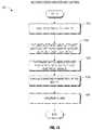
- a method controlling priming of a catheter assemblycan include generating a first user interface including a first instruction corresponding to priming of a catheter assembly to remove gas from the catheter assembly prior to a treatment procedure.
- the methodcan further include monitoring one or more sensors of a fluid handling system, the fluid handling system configured to prime the catheter assembly to remove the gas.
- the methodcan additional include the step of determining a system condition based in part on the monitoring of the one or more sensors.
- the methodcan further include controlling an operation of a component of the fluid handling system based on the determined system condition.
- the operationincludes directing fluid distally through the catheter assembly to remove the gas.
- the method of the preceding paragraphcan have any sub-combination of the following features: wherein the detection of the connection state comprises measuring a flow of current or voltage across two electrical terminals wherein the sending instructions comprises sending a drive signal to a motor configured to drive a pump that directs fluid distally through the catheter assembly to remove the gas.
- the method of the preceding paragraphcan also include any of the features described in paragraph 19 above.
- a control systemcan control operation of a catheter assembly.
- the control systemcan include one or more hardware processors.
- the one or more hardware processorscan transmit a drive signal to an impeller motor configured to impart rotation to an impeller to pump blood.
- the one or more hardware processorscan receive electrical signals from at least one of the following: a plurality of sensors, a cassette connector, and the impeller motor.
- the one or more hardware processorscan determine one or more motor parameters from the received electrical signals.
- the one or more hardware processorscan also change operating parameters of the impeller motor based on the determined one or more motor parameters, thereby controlling pumping of blood.
- the control system of the preceding paragraphcan have any sub-combination of the following features: wherein the one or more motor parameters include a current drawn by the impeller motor; wherein the one or more hardware processors can compare the current drawn by the impeller motor to a threshold current; the threshold current includes a value greater than 1 ampere; wherein the one or more motor parameters include a flow rate generated by the impeller motor; wherein the one or more motor parameters include a temperature of the impeller motor; wherein the one or more motor parameters include a motor speed; wherein the changing of operating parameters of the impeller motor based on the determined motor parameters includes comparing the determined one or more motor parameters to one or more predetermined thresholds.
- the control system of the preceding paragraphcan use any of the features described in paragraph 19 .
- a fluid handling systemcan include a console that can connect with a first electrical interface of a cassette which can connect to a plurality of components of the fluid handling system.
- the consolecan further include a second electrical interface that can connect with the first electrical interface, a display, and one or more hardware processors.
- the fluid handling systemcan include a control system that includes the one or more hardware processors.
- the control systemcan detect an electrical signal from a first component of the plurality of components of the fluid handling system responsive to a caretaker performing a first instruction.
- the control systemcan determine a system state of the fluid handling system based at least in part on the electrical signal from the first component.
- the control systemcan compare the system state with a predetermined state condition corresponding to said first instruction.
- the fluid handling system of the preceding paragraphcan have any sub-combination of the following features: wherein the control system can generate a first user interface including a visual indication of the first instruction; generate a second user interface including a visual indication of a second instruction based at least on the comparison indicating that the system state is within predetermined state condition and the first instruction is completed; generate an alarm based at least on said comparison indicating that the system state is not within predetermined state condition; detect connection state between the cassette and the console; send instructions to begin priming based on the detected connection state between the cassette and the console and the determined system state; determine a temperature of an impeller moto that rotates the impeller to pump blood and shut off the impeller motor responsive to the determination of the temperature of the impeller motor; to determine a current drawn by the impeller motor and shut off the impeller motor responsive to the determination of the current drawn by the impeller motor; to determine blockage of fluid in a catheter and trigger an alarm based on the determination of blockage.
- the control system of the fluid handling system of the preceding paragraph
- a computer storage system including a non-transitory storage devicecan include stored executable program instructions.
- the program instructionscan direct a computer system to generate a first user interface including a first instruction corresponding to priming of a catheter assembly to remove gas from the catheter assembly prior to a treatment procedure.
- the program instructionscan further direct the computer system to monitor one or more sensors of a fluid handling system, the fluid handling system configured to prime the catheter assembly to remove the gas.
- the program instructionscan further direct the computer system determine a system condition based in part on the monitoring of the one or more sensors.
- the program instructionscan direct the computer system to control an operation of a component of the fluid handling system based on the determined system condition.
- the operationincludes directing fluid distally through the catheter assembly to remove the gas.
- the program instructioncan also direct the computer system to generate an alarm based on the determined system conditions.
- the program instructionscan direct the computer system to use or execute any of the features of paragraph 19 .
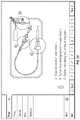
- FIG. 1is a schematic view of an operative device of a catheter assembly in position within the anatomy for assisting the left ventricle.
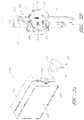
- FIG. 2is a three-dimensional perspective view of a catheter assembly, according to some embodiments.
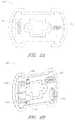
- FIG. 3Ais a three-dimensional perspective view of a fluid handling system that includes a console and catheter assembly.
- FIG. 3Bis a three-dimensional perspective view of an interface region of the console shown in FIG. 3A .
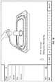
- FIG. 4is a three-dimensional perspective view of an interface member, according to one embodiment.
- FIG. 5Ais a three-dimensional perspective view of a cap.
- FIG. 5Bis a three-dimensional perspective view of an interface member in an unlocked configuration.
- FIG. 5Cis a three-dimensional perspective view of an interface member in a locked configuration.
- FIG. 6Ais a three-dimensional perspective view of a first side of an electrical component, according to one embodiment.
- FIG. 6Bis a three-dimensional perspective view of a second, opposite side of the electrical component of FIG. 6A .
- FIG. 7is a schematic diagram of an infusate system, according to one embodiment.
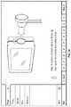
- FIG. 8is an enlarged view of a priming apparatus shown in FIG. 2 .
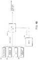
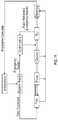
- FIG. 9illustrates a block diagram of a console and the electrical connections between the console and the various components of the fluid handling system, according to one embodiment.
- FIG. 10illustrates a block diagram of the inputs and outputs of a control system, according to one embodiment.
- FIG. 11illustrates a flow chart of a process 1100 that can be managed using the control system, according to one embodiment.
- FIG. 12illustrates a process 1200 for using the control system to assist with the priming process, according to one embodiment.
- FIG. 13illustrates a process 1300 for controlling operation of the motor using the control system, according to one embodiment.
- FIG. 14illustrates an embodiment of a startup user interface, according to one embodiment.
- FIG. 15illustrates system setup user interface for changing settings related to the console, according to one embodiment.
- FIG. 16illustrates a save data user interface generated by the control system, according to one embodiment.
- FIG. 17illustrates a first prep screen user interface generated by the control system, according to one embodiment.
- FIG. 18illustrates a second prep screen user interface generated by the control system, according to one embodiment.
- FIGS. 19 to 24illustrate user interfaces corresponding to instructions relating to insertion of cassette (or puck), according to one embodiment.
- FIG. 21illustrates a user interface corresponding to hanging waste bag on hook, according to one embodiment.
- FIG. 22illustrates user interface generated by the control system for instructions corresponding to the sixth step in the prepping process, according to one embodiment.
- FIG. 23illustrates a user interface generated by the control system including instruction to unclamp the line connecting to the pressurized saline bag, according to one embodiment.
- FIG. 24illustrates a user interface generated by the control system including instructions to insert cassette into the console, according to one embodiment.
- FIG. 25illustrates a user interface generated by the control system indicating that the cassette was successfully connected with the console, according to one embodiment.
- FIG. 26illustrates a user interface displaying the indication of progress, according to one embodiment.
- FIG. 27illustrates a user interface generated by the control system indicating that the priming process has been completed, according to one embodiment.
- FIG. 28illustrates a user interface including an alert history during operation of fluid handling system, according to one embodiment.
- FIG. 29illustrates a user interface for alerting the user when the puck is disconnected, according to one embodiment.
- FIG. 30illustrates a user interface generated by the control system indicating that there is air in the saline supply line, according to one embodiment.
- FIG. 31illustrates a user interface generated by the control system based on a detection of temperature of the handle, according to one embodiment.
- FIG. 32illustrates a user interface generated by the control system in response to monitoring outer sheath pressure, according to one embodiment.
- FIG. 33illustrates a user interface generated by the control system in response to monitoring saline flow, according to one embodiment.
- FIG. 34illustrates a user interface generated by the control system in response to detecting outer sheath pressure, according to one embodiment.
- FIG. 35illustrates a user interface generated by the control system in response to monitoring the unlock button, according to one embodiment.
- FIG. 36illustrates a user interface generated by the control system based on monitoring of waste line pressure sensor, according to one embodiment.
- FIG. 37illustrates a user interface generated by the control system based on monitoring device in the patient, according to one embodiment.
- FIGS. 38, 39, and 40illustrate user interfaces generated by the control system in response to monitoring temperature, according to one embodiment.
- FIG. 41illustrates a user interface generated by the control system in response to monitoring connection status of the puck, according to one embodiment.
- FIGS. 42 to 45illustrate user interfaces generated by the control system in response to monitoring cannula position, according to one embodiment.
- the disclosed percutaneous heart pump systemsmay include a catheter assembly and a console that includes a controller configured to control the fluid and electrical pathways that pass through the catheter assembly.
- the consolemay be configured to control the flow rate of the pump and to monitor various physiological parameters and pump performance through the various electrical and fluid pathways of the catheter assembly.
- the catheter assemblymay be disposable, such that the catheter assembly can be discarded after use, while the console and controller are reusable.
- an interface member at a proximal portion of the catheter assemblythat is removably engageable with the console.
- it can be important to make the interface easy to useso that users can easily connect the catheter assembly to the console before use and easily remove the catheter assembly from the console after use.
- the interfaceprovides a secure connection between the interface member of the catheter assembly and an interface region of the console to ensure that the catheter assembly remains connected to the console uninterrupted during treatment.
- a catheter assemblyis used in a percutaneous heart pump system having an operative device (e.g., an impeller assembly) that is configured to assist the patient's heart in pumping blood.
- the heart pump systemmay be configured to at least temporarily support the workload of the left ventricle in some embodiments.
- the exemplary heart pumpcan be designed for percutaneous entry through the femoral artery to a patient's heart.
- the exemplary impeller assemblycan include a collapsible impeller and cannula, which can be inserted into the patient's vasculature at a catheter size of less than 13 FR, for example, about 12.5 FR in some arrangements.
- a sheathmay maintain the impeller and cannula assembly in a stored configuration.
- the impeller and cannulacan expand to a larger diameter, for example to a catheter size of about 24 FR when the sheath is removed from the impeller assembly.
- the expanded diameter of the impeller and cannulamay allow for the generation of higher flow rates, according to some embodiments.
- FIG. 1illustrates one use of the disclosed catheter pump system.
- a distal portion of the pumpwhich can include an impeller assembly 116 A, is placed in the left ventricle (LV) of the heart to pump blood from the LV into the aorta.
- the pumpcan be used in this way to treat patients with a wide range of conditions, including cardiogenic shock, myocardial infarction, and other cardiac conditions, and also to support a patient during a procedure such as percutaneous coronary intervention.
- One convenient manner of placement of the distal portion of the pump in the heartis by percutaneous access and delivery using the Seldinger technique, or other methods familiar to cardiologists. These approaches enable the pump to be used in emergency medicine, a catheter lab and in other non-surgical settings.
- Modificationscan also enable the pump 10 to support the right side of the heart.
- Example modifications that could be used for right side supportinclude providing delivery features and/or shaping a distal portion that is to be placed through at least one heart valve from the venous side, such as is discussed in U.S. Pat. Nos. 6,544,216; 7,070,555; and US 2012-0203056A1, all of which are hereby incorporated by reference herein in their entirety for all purposes.
- the catheter assembly 100 Amay correspond to the disposable portion of the heart pump systems described herein.
- the catheter assembly 100 Amay include the impeller assembly 116 A near a distal portion of the catheter assembly 100 A, an elongate body 174 A extending proximally from the impeller assembly 116 A, an infusion system 195 configured to supply infusate to the catheter assembly 100 A, a motor assembly comprising a driven assembly 101 and a drive assembly 103 , one or more conduits 302 (e.g., electrical and/or fluid conduits) extending proximally from the motor assembly, and an interface member 300 coupled at a proximal portion of the conduits 302 .
- conduits 302e.g., electrical and/or fluid conduits
- the impeller assembly 116 Amay be disposed at a distal portion of the catheter assembly 100 A.
- the impeller assembly 116 Acan include an expandable cannula or housing and an impeller with one or more blades. As the impeller rotates, blood can be pumped proximally (or distally in some implementations) to function as a cardiac assist device.
- a priming apparatus 1400can be disposed over the impeller assembly 116 A. As explained herein with reference to FIGS. 7-8 , the priming apparatus 1400 can be configured to expedite a process of expelling air from the catheter assembly 100 A before insertion of the operative device of the catheter assembly into the patient.
- the elongate body 174 Aextends proximally from the impeller assembly 116 A to an infusion system 195 configured to allow infusate to enter the catheter assembly 100 A and waste fluid to leave the catheter assembly 100 A.
- a catheter body 120 A(which also passes through the elongate body 174 A) can extend proximally and couple to the driven assembly 101 of the motor assembly.
- the catheter body 120 Acan pass within the elongate body 174 A, such that the elongate body 174 A can axially translate relative to the catheter body 120 A.
- Axial translation of the elongate body 174 A relative to the catheter body 120 Acan enable the expansion and collapse of the impeller assembly 116 A.
- the impeller assembly 116 Acoupled to a distal portion of the catheter body 120 A, may expand into an expanded state by moving the elongate body 174 A proximally relative to the impeller assembly 116 A.
- the impeller assembly 116 Amay self-expand into the expanded state in some embodiments. In the expanded state, the impeller assembly 116 A is able to pump blood at high flow rates.
- the impeller assembly 116 Amay be compressed into a collapsed state by advancing a distal portion 170 A of the elongate body 174 A distally over the impeller assembly 116 A to cause the impeller assembly 116 A to collapse.
- the catheter body 120 Acan couple to the driven assembly 101 of the motor assembly.
- the driven assembly 101can be configured to receive torque applied by the drive assembly 103 , which is shown as being decoupled from the driven assembly 101 and the catheter assembly 100 A in FIG. 2 .
- the drive assembly 103can be coupled to the driven assembly 101 by engaging a proximal portion of the driven assembly 101 with the drive assembly, e.g., by inserting the proximal portion of the driven assembly 101 into an aperture 105 of the drive assembly 103 .
- a drive shaftcan extend from the driven assembly 101 through the catheter body 120 A to couple to an impeller shaft at or proximal to the impeller assembly 116 A.
- the drive assembly 103can electrically communicate with a controller in a console (see, e.g., FIGS. 3A-3B ), which can be configured to control the operation of the motor assembly and the infusion system 195 that supplies a flow of infusate in the catheter assembly 100 A.
- the impeller of the impeller assembly 116 Amay thus be rotated remotely by the motor assembly during operation of the catheter pump in various embodiments.
- the motor assemblycan be disposed outside the patient.
- the motor assemblyis separate from the controller or console, e.g., to be placed closer to the patient. In other embodiments, the motor assembly is part of the controller. In still other embodiments, the motor assembly is miniaturized to be insertable into the patient. Such embodiments allow the drive shaft to be much shorter, e.g., shorter than the distance from the aortic valve to the aortic arch (about 5 cm or less).
- the motor assembly(e.g., the drive assembly 103 and the driven assembly 101 ) is in electrical communication with the controller and console by way of the conduits 302 , which may include electrical wires.
- the electrical wiresmay extend from the motor assembly proximally to the interface member 300 .
- the controller in the consoleto electrically communicate with the motor assembly and/or other sensors in the catheter assembly 100 A (such as pressure sensors, flow sensors, temperature sensors, bubble detectors, etc.), it can be advantageous to provide a reliable electrical connection between the interface member 300 and the console.
- the removable interface member 300may include electrical components configured to couple to one or more electrical contacts (sometimes referred to herein as interconnections) in the console.
- the electrical connectionsmay be achieved in a simple, user-friendly manner.
- the electrical connectionsmay be made substantially at the same time, e.g., substantially simultaneously, as fluid connections are made between the interface member 300 and console.
- the mechanical components rotatably supporting the impeller within the impeller assembly 116 Apermit high rotational speeds while controlling heat and particle generation that can come with high speeds.
- the infusion system 195may deliver a cooling and lubricating solution to the distal portion of the catheter assembly 100 A for these purposes. As shown in FIG. 2 , the infusion system 195 may be in fluid communication with the interface member 300 by way of the conduits 302 , which may also include fluid conduits or tubes. Because the catheter assembly 100 A may be disposable and/or removable from a console, it can be important to securely couple interface member 300 to the console. Furthermore, it can be important to provide an easy-to-use interface such that users can easily complete fluid connections that remain secure during a treatment procedure.
- Maintaining security of the connectionis important because the fluids and signals carried by the conduits 302 enable the impeller to operate in a continuous manner. Stoppage of the pump system may require the catheter assembly 100 A to be removed from the patient and replaced in certain circumstances, which may be life-threatening or extremely inconvenient at a minimum.
- the catheter pump systemWhen activated, the catheter pump system can effectively increase the flow of blood out of the heart and through the patient's vascular system.
- the pumpcan be configured to produce a maximum flow rate (e.g. low mm Hg) of greater than 4 Lpm, greater than 4.5 Lpm, greater than 5 Lpm, greater than 5.5 Lpm, greater than 6 Lpm, greater than 6.5 Lpm, greater than 7 Lpm, greater than 7.5 Lpm, greater than 8 Lpm, greater than 9 Lpm, or greater than 10 Lpm.
- a maximum flow ratee.g. low mm Hg
- the pumpcan be configured to produce an average flow rate at 62 mmHg pressure head of greater than 2 Lpm, greater than 2.5 Lpm, greater than 3 Lpm, greater than 3.5 Lpm, greater than 4 Lpm, greater than 4.25 Lpm, greater than 4.5 Lpm, greater than 5 Lpm, greater than 5.5 Lpm, or greater than 6 Lpm.
- FIG. 3Ais a three-dimensional perspective view of a fluid handling system 350 that includes a console 301 and the catheter assembly 100 A of FIG. 2 .
- the console 301can provide electrical power, control signals, medical fluids (e.g., saline) for infusion, and fluid waste extraction to the catheter assembly 100 A by way of its interface with the interface member 300 .
- medical fluidse.g., saline
- the removable interface member 300may be disposed at a proximal portion of the catheter assembly 100 A and may be configured to couple to the console 301 at an interface region 303 .
- the fluid handling system 350can be configured to deliver fluids to and/or remove fluids from the catheter assembly 100 A.
- saline and/or other medical solutionscan lubricate and/or cool component between the motor assembly and the operative device.
- waste fluidscan be removed from the catheter assembly 100 A using the fluid handling system 350 .
- the fluid handling system 350can include a multilumen catheter body having a proximal end and a distal end. The catheter body can include one or more lumens through which medical solutions (e.g., saline), waste fluids, and/or blood can flow.
- the console 301may include one or more pump(s) configured to apply positive or negative pressure to the catheter assembly 100 A when the catheter assembly 100 A is coupled to the console 301 and engages the pump(s).
- the fluid handling system 350may also be configured to provide electrical communication between the console 301 and the catheter assembly 100 A.
- the consolecan include a controller (e.g., a processor) that is programmed to control and/or manage the operation of the motor assembly.
- the console 301may also include electrical interfaces configured to supply power to the motor assembly and/or other components that are driven by electrical power when the interface member 300 is coupled to the console 301 .
- one or more electrical or electronic sensorsmay be provided in the catheter assembly 100 A and may electrically couple to the console 301 by way of the fluid handling system 350 . The embodiments disclosed herein may thereby provide fluid and electrical connections between the catheter assembly 100 A and the console 301 .
- the fluid handling system 350may provide a removable interface between the catheter assembly 100 A and the console 301 , which may include various components, including, e.g., one or more pump(s), processors (e.g., the controller), electrical interconnections, etc.
- a usermay simply insert a distal portion of the interface member 300 (e.g., including a closure member) along the illustrated Z-direction into an aperture 304 of the interface region 303 until the pump(s) are engaged and the electrical connection(s) are formed.
- the insertion of the interface member along the Z-directionmay engage the pump(s) and complete the electrical connection(s) substantially simultaneously.
- the interface member 300may be secured to the console 301 by engaging a locking device between the interface region 303 and the interface member 300 .
- a locking deviceis by rotating a portion of the interface member 300 relative to another portion of the interface member or relative to the console 301 , as explained herein.
- rotation of an outermost structure(opposite the direction Z), sometimes referred to herein as a “cap” relative to the console may engage a locking mechanism configured to mechanically secure the interface member 300 to the console 301 to prevent the interface member 300 from being accidentally disengaged during a treatment procedure.
- the console 301may also include a user interface 312 , which may comprise a display device and/or a touch-screen display.
- the usermay operate the percutaneous heart pump system by interacting with the user interface 312 to select, e.g., desired flow rates and other treatment parameters.
- the usermay also monitor properties of the procedure on the user interface 312 .
- FIG. 3Bis a three-dimensional perspective view of the interface region 303 of the console 301 shown in FIG. 3A .
- the interface region 303can include the aperture 304 configured to receive the distal portion of the interface member 303 .
- the aperture 304may include a generally circular cavity shaped and sized to receive a portion of the interface member 300 .
- a bubble detector 308e.g., an optical sensor in some embodiments
- the bubble detector 308may include a recess portion defined by two walls sized and shaped to receive a segment of tubing. When fluid flows through the tubing (see, e.g., bubble detector tube segment 326 in FIG.
- the bubble detector 308may monitor the fluid to determine whether or not the fluid includes unwanted matter, e.g., bubbles of air or other gas. In some embodiments, the bubble detector 308 may measure the amount (number or volume) of bubbles in the fluid passing though the tube segment. It should be appreciated that it can be important to detect bubbles in the treatment fluid to avoid inducing embolisms in the patient.
- the bubble detector 308may electrically communicate with the controller in the console 301 and can indicate the amount of bubbles in the treatment fluid. The console 301 , in turn, can alert the user if there are bubbles in the treatment fluid.
- the interface region 303can also include one or more pumps, e.g., peristaltic pumps in some embodiments.
- the peristaltic pumpscan be used to pump fluid into or out of the catheter assembly 100 A to deliver medical fluids and to remove waste fluids, respectively.
- Such pumpsmay employ one or more rollers 306 to control delivery of a fluid within a respective tube (see, e.g., pump tube segments 324 a , 324 b of FIG. 4 ).
- the one or more pump rollers 306can be housed within the console 301 .
- two pump rollers 306are mounted about their rotational axes (e.g., the Y-direction illustrated in FIG. 3B ) at the back wall of the aperture 304 .
- the pump rollers 306can be rotated by a peristaltic pump motor within the console (not shown in FIGS. 3A-3B ). As explained in more detail herein with respect to FIG. 4 below, the rollers 306 can engage pump tube segments 324 a , 324 b to pump fluid into or out of the catheter assembly 100 A.
- the pump rollers 306may be configured to be received within occlusion bed regions of the interface member 300 (see, e.g., occlusion beds 322 a and 322 b of FIG. 4 ) to pump fluid through the catheter assembly 100 A.
- An electrical interconnect 307can also be provided in the back wall of the aperture 304 .
- the electrical interconnect 307can be configured to provide power to the motor assembly and/or electrical signals or instructions to control the operation of the motor assembly.
- the electrical interconnect 307can also be configured to receive electrical signals indicative of sensor readings for monitoring pressure, flow rates, and/or temperature of one or more components in the catheter assembly 100 A.
- a recessed channel 309can extend from the bottom of the aperture 304 along the side to the lower edge of the console 301 .
- the recessed channel 309can be shaped and sized to receive one or more of the conduits 302 (e.g., electrical and/or fluid conduits) extending between the interface member 300 and the motor assembly. In one embodiment, all of the conduits 302 can be received within the channel 309 providing a flush side surface when the interface member 300 is disposed in the interface aperture 304 .
- the interface region 303can include a groove 313 sized and shaped to receive a locking mechanism (e.g., a tab or flange projecting in the X direction) on the interface member 300 .
- a disengaging member 305includes a spring-loaded release mechanism 310 provided above the aperture 304 and a pin 311 that can be inserted into a hole in the interface member 300 (see, e.g., FIGS.
- the pin 311can assist in releasing the interface member 300 relative to the console 301 .
- the spring-loaded release mechanism 310can be pressed to release the pin 311 and unlock the interface member 300 from the console 301 .
- the spring-loaded release mechanism 310can therefore act as a further safety mechanism to ensure that the cassette is not accidentally disengaged by the user.
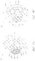
- FIG. 4is a three-dimensional perspective view of the interface member 300 , according to one embodiment.
- the interface member 300can comprise a body that is shaped and sized to fit into the interface region 303 of the console 301 . As shown in FIG. 4 , the interface member 300 can have a substantially circular profile, and is sometimes referred to as a puck.
- the interface member 300can include an outer body 333 operably coupled to a manual interface 320 , sometimes referred to as a cap.
- the manual interface 320is generally palm-sized so that a user can receive it in their hand and operate it comfortably, e.g., with finger pressure on the outer rim of the cap.
- One or more occlusion bedscan be formed or provided at the interface between the interface member 300 and the console 301 , e.g., in or on the interface member 300 .
- first and second occlusion beds 322 a and 322 bmay be formed in the interface member 300 .
- the occlusion beds 322 a , 322 bcan include arcuate recessed regions formed in the interface member 300 .
- the interface member 300can further include first and second pump tube segments 324 a , 324 b positioned along the occlusion beds 322 a , 322 b formed in the interface member 300 .
- the pump rollers 306can engage with the interface member 300 and compress the tube segment(s) 324 a , 324 b against the occlusion bed(s) 322 a , 322 b , respectively.
- the pump motor(s) in the console 301rotate the rollers 306 , fluid flows into uncompressed portions of the tube segment(s) 324 a , 324 b and continues flowing throughout the catheter assembly 100 A.
- the fluidmay be pumped into or out of the catheter assembly 100 A by way of the conduits 302 extending from the interface member 300 to the motor assembly and distally beyond the motor assembly.
- the body of the interface member 300(e.g., the outer body 333 and/or an inner body, such as inner body 339 illustrated in FIGS. 5B-5C ) can be formed with precise tolerances (e.g., molded from a unitary structure in some implementations) such that when the interface member 300 is inserted into the console 301 , the pump rollers 306 precisely and automatically engage with the tube segments 324 a , 324 b and occlusion beds 322 a , 322 b to reliably occlude the tube segments 324 a , 324 b and pump fluids through the catheter assembly 100 A.
- the pump in the console 301can automatically engage the interface member 300 .
- the gap between the rollers 306 and the occlusion beds 322 a , 322 bcan be less than about two wall thicknesses of the tube segments 324 a , 324 b in some arrangements, such that the tubes 324 a , 324 b can be effectively occluded.
- the pumpcan be engaged by simply inserting the interface member 300 into the console 301 . There is no need to separately activate the pump in some embodiments.
- the dimensions of the interface member 300may be selected such that the occlusion bed(s) 322 a , 322 b automatically engages the respective pump rollers 306 upon insertion of the interface member 300 into the console 301 .
- the interface member 300 and interface region 303provide an easy-to-use, quick connection of the tubing segments to one or more respective rollers 306 .
- the componentscan be manufactured easily and cost-effectively because only certain components require tight tolerances and the interface of member 300 to region 303 is essentially self-aligning.
- the interfacealso eliminates any need to engage the pump through a second mechanism or operator step, streamlining operation of the heart pump and simplifying the engagement of the catheter assembly 100 A to the console 301 .
- the simplified engagement mechanisms disclosed hereincan be advantageous because there is only a minimal applied force against the pole, which prevents the pole from rolling or tipping when the pump is engaged.
- the pump tube segments 324 a , 324 bcan be mounted on the interface body 300 near or in the respective occlusion beds 322 a , 322 b .
- the first and second pump tube segments 324 a , 324 bcan be configured to engage with the pump rollers 306 in the console 301 , as explained above.
- the first and second pump tube segments 324 a , 324 bcan have an arcuate shape (which may be pre-formed in various arrangements) that generally conforms to the curved shape of each respective occlusion bed 322 a , 322 b .
- the pump rollers 306 within the console 301can thereby be positioned within the occlusion beds 322 a , 322 b to compress the tube segments 324 a , 324 b against the wall of the occlusion beds 322 a , 322 b .
- a bubble detector tube segment 326can also be mounted in or on the interface member 300 and can be configured to engage with or be positioned adjacent to the bubble detector 308 illustrated in FIG. 3B .
- the bubble detector tube segment 326can be any suitable shape.
- the bubble detector tube segmentcan be substantially straight and can be sized and shaped to be received by the bubble detector 308 within the console 301 .
- the bubble detector 308(which may be an optical sensor) can be used to detect air bubbles in the treatment or lubricating fluid being supplied to the patient.
- the tube segmentscan be fluidly connected to the remainder of the catheter assembly 100 A, including, e.g., one or more lumens of the catheter body, by way of the conduits 302 .
- the removable interface member 300may allow fluid to be pumped into and out of the patient within a controlled system, e.g., such that the fluids within the catheter assembly 100 A can be pumped while maintaining a sterile environment for the fluids.
- the volume of medical solution into the catheter bodycan be equal to, or can exceed by a minimum amount, the volume of medical solution out of the catheter body to assure that blood does not enter a blood-free portion of the heart pump.
- one or more electrical contacts 328can be provided in the interface member 300 .
- the electrical contacts 328can be any suitable electrical interface configured to transmit electrical signals between the console 301 and the catheter assembly 100 A (e.g., the motor assembly and/or any suitable sensors).
- the electrical contacts 328can be configured to electrically couple to the electrical interconnect 307 disposed in the console 301 . Electrical control signals and/or power may be transmitted between the console 301 and the catheter assembly 100 A by way of the electrical connection between the electrical contacts 328 and the electrical interconnect 307 .
- the electrical connection between the electrical contacts 328 and the electrical interconnect 307may be formed or completed when the interface member 300 is inserted into the interface region 303 of the console 301 .
- the electrical connection between the electrical contacts 328 and the electrical interconnect 307may be formed substantially simultaneously with the fluid connection (e.g., the engagement of the pump) when the interface member 300 is inserted into the interface region 303 .
- the electrical connectioncan be formed by inserting electrical pins from the electrical contacts 328 into corresponding holes of the electrical interconnect 307 of the console 301 , or vice versa.
- the manual interface 320can be mechanically coupled to a proximal portion of the outer body 333 and may be configured to rotate relative to the outer body 333 in a constrained manner, as explained below relative to FIGS. 5A-5C .
- the outer body 333can include one or more locking apertures 331 configured to receive locking tabs 332 that are configured to lock the manual interface 320 relative to the console 301 .
- the outer body 333may include a pin hole 321 sized and shaped to receive the pin 311 illustrated in FIG. 3B to releasably couple the removable interface member 300 relative to the console 301 .
- the configuration of the pump rollers, occlusion bed, and tubingcan be modified depending on the application in accordance with the present inventions.
- the configurationmay be modified to provide easier access for service and repair.
- the pump rollersmay be disposed external to the console.
- the pump rollers and occlusion bedmay be both disposed within the cassette.
- the consoleincludes a mechanism to actuate the pump rollers in the cassette.
- the rollersmay be fixed.
- the rollersmay be configured to rotate, translate, or both.
- the rollers and/or the occlusion bedmay be positioned on a base that is configured to move.
- the console-cassette interfacecan include a positive pressure interface to pump fluid (e.g., saline) into the patient's vasculature and a negative pressure interface to pump fluid (e.g., waste fluid) out of the patient's vasculature.
- pump fluide.g., saline
- negative pressure interfaceto pump fluid (e.g., waste fluid) out of the patient's vasculature.
- the interface member 300advantageously can be fully engaged with the console 301 by simply inserting it into a correspondingly shaped aperture 304 in the housing of the console 301 .
- a locking mechanism in the interface member 300can be provided for additional security, which can be particularly useful for patient transport and other more dynamic settings. For example, it is desirable to ensure that the catheter assembly 100 A is secured to the console 301 during the entire procedure to ensure that the procedure is not disrupted due to accidental disengagement of the interface member 300 from the console 301 .
- the locking mechanismcan be disposed between the console 301 and the interface member 300 and can be configured to be engaged by a minimal movement of an actuator.
- the manual interface 320can be provided to cause engagement of a locking device by a small rotational turn of the manual interface 320 relative to the console 301 .
- FIG. 5Ais a three-dimensional perspective view of the manual interface 320 .
- the manual interface 320can include or be coupled with an internal cam 335 .
- the cam 335can include one or more protruding lobes, such as lobes 336 a and 336 b . Further, the cam 335 can include a recessed region 337 recessed inwardly relative to the lobes 336 a , 336 b .
- the cam 335can also include a stepped region 338 which can enable the interface member 300 to be locked and unlocked relative to the console 301 , as explained herein.
- FIG. 5Bis a three-dimensional perspective view of an interface member 300 A in an unlocked configuration
- FIG. 5Cis a three-dimensional perspective view of an interface member 300 B in a locked configuration.
- the interface members 300 A, 300 B of FIGS. 5B and 5Care illustrated without the outer body 333 , which has been hidden in FIGS. 5B and 5C for purposes of illustration.
- the components of FIGS. 5B and 5Care the same as or similar to the components illustrated with respect to FIG. 4 .
- the interface members 300 A, 300 Bcan include an inner body 339 that can be disposed within the outer body 333 shown in FIG. 4 .
- the occlusion beds 322 a , 322 bcan be formed in the inner body 339 of the interface member 300 A, 300 B, as shown in FIGS. 5B-5C ; however, in other arrangements, the occlusion beds 322 a , 322 b may be formed in the outer body 333 or other portions of the interface member 300 A, 300 B.
- an electrical component 340can be disposed in a recess or other portion of the inner body 339 . Additional details regarding the electrical component 340 are explained below with respect to FIGS. 6A-6B .
- the inner body 339 of the interface member 300 A, 300 Bcan further include a protrusion 330 that includes the tab 332 at a distal portion of the protrusion 330 .
- the protrusion 330can be disposed in or near the recess 337 of the cam 335 in the manual interface 320 .
- the cam 335may therefore not contact or apply a force against the protrusion 330 when the interface member 300 A is in the unlocked configuration, as shown in FIG. 5B .
- the interface member 300can be locked into place by rotating the manual interface 320 relative to the inner body 339 and the console 301 , e.g., rotated in the A-direction illustrated in FIG. 5B .
- the internal cam 335is also rotated within the interface member 300 A, 300 B.
- the lobes 336 a , 336 b of the cam 335can engage with the one or more protrusions 330 of the inner body 339 and can push the protrusions 330 outwardly relative to the inner body 339 .
- the tabs 332may extend outwardly through the locking apertures 331 formed on the outer body 333 .
- the tabs 332When the tab(s) 332 are pushed through the locking aperture(s) 331 , the tabs 332 project laterally outward from the outer body 333 .
- each of the tabs 332can lock into the groove(s) 313 in the console 301 (see FIG. 3B ) to secure the interface member 300 B to the console 301 .
- the tab 332in the unlocked position, the tab 332 can be substantially flush with the outer surface of the interface member 300 A, and in the locked position, the tab 332 can extend through the locking aperture 331 and lock into the grooves 313 in the console 301 .
- the protrusion 330can be a cantilevered protrusion from the inner body 339 .
- itcan be important to maintain tight tolerances between the occlusion beds 322 a , 322 b , which is also formed in the interface member, and the pump rollers 306 when the interface member 300 engages with the console 301 .
- the occlusion beds 322 a , 322 bmay be formed in the same body as the cantilevered protrusions 330 , conventional manufacturing processes, such as molding processes, can be used to manufacture the interface member 300 (e.g., the outer body 333 and/or the inner body 339 ) according to precise dimensions.
- the protrusion(s) 330 , tab(s) 332 and the occlusion bed(s) 322 a , 322 bcan be made within tight dimensional tolerances, and the tab(s) 332 and/or protrusion(s) 330 can be positioned relative to the occlusion bed(s) 322 a , 322 b with very high precision such that when the interface member 300 is engaged with the console 301 , the tube segments 324 a , 324 b are optimally occluded.
- the interface member 300can be locked by rotating the manual interface 320 on the interface member 300 , only minimal forces are applied to the console 301 . This enhances the advantages of minimizing disruption of a mobile cart or IV pole to which the system may be coupled.
- the disengaging member 305 of the console 301can be configured to disengage and unlock the interface member 300 from the console 301 .
- the pin 311may be spring-loaded such that when the interface member 300 A is in the unlocked configuration, the pin 311 extends through the pin hole 321 of the outer body 333 but only contacts a side surface of one of the lobes 336 b of the cam 335 .
- the pin 311may simply slide along the cam surface, permitting rotation of the manual interface 320 relative to the pin 311 and the console 301 .
- the pin 311can engage with the stepped region 338 of the internal cam 335 , e.g., the spring-biased pin 311 can extend into the stepped region 338 or shoulder of the cam 335 .
- the pin 311prevents the cam 335 from rotating from the locked configuration to the unlocked configuration.
- a usercan disengage the cassette by pressing the spring-loaded release mechanism 310 to release the spring and remove the pin 311 from the stepped region 338 .
- the pin 311can thereby be disengaged from the stepped region 338 , and the internal cam 335 can rotate back into the unlocked position.
- the tab 332can be withdrawn from the groove 313 in the console 301 to unlock the interface member 300 .
- FIG. 6Ais a three-dimensional perspective view of a first side of the electrical component 340 illustrated in FIG. 4 .
- FIG. 6Bis a three-dimensional perspective view of a second, opposite side of the electrical component 340 of FIG. 6A .
- the electrical component 340may be disposed in a recess of the interface member 300 .
- the electrical component 340can be any suitable electrical or electronic component, including, e.g., a printed circuit board (PCB) configured to provide an electrical interface between various components in the catheter assembly 100 A and the console 301 .
- the electrical component 340can form an electrical interface between the interface member 300 and the console 301 to provide electrical communication between the console 301 and the catheter assembly 100 A (such as the motor assembly and/or various sensors).
- the electrical component 340 of the interface member 300can include the one or more electrical contacts 328 configured to mate with the corresponding electrical interconnect 307 in the console 301 .
- the electrical contacts 328 and/or the electrical interconnect 307can be, for example, nine-pin electrical interconnects, although any suitable interconnect can be used.
- the motor assembly that drives the operative device (e.g., impeller) of the catheter pumpcan be electrically connected to the interface member 300 by way of one or more electrical cables, e.g., the conduits 302 .
- the console 301can be coupled to a power source, which can drive the catheter pump motor assembly by way of the interface member's contacts 328 and the electrical conduits 302 connecting the interface member 300 to the motor assembly.
- the electrical component 340can also include communications interconnects configured to relay electrical signals between the console 301 and the catheter pump motor assembly or other portions of the catheter assembly 100 A.
- a controller within the console 301 (or interface member)can send instructions to the catheter pump motor assembly via the electrical component 340 between the console 301 and the interface member 300 .
- the electrical component 340can include interconnects for sensors (such as pressure or temperature sensors) within the catheter assembly 100 A, including sensors at the operative device.
- the sensorsmay be used to measure a characteristic of the fluid in one or more of the tubes (e.g., saline pressure).
- the sensorsmay be used to measure an operational parameter of the system (e.g., ventricular or aortic pressure).
- the sensorsmay be provided as part of an adjunctive therapy.
- the electrical component 340 within the interface member 300can be used to electrically couple the cable (and the motor assembly, sensors, etc.) with the corresponding interconnects 307 in the console 301 .
- one or more internal connectors 346 and 348 on the second side of the electrical component 340may provide electrical communication between the contacts 328 (configured to couple to the interconnects 307 of the console 301 ) and the catheter assembly 100 .
- electrical cablese.g., the conduits 302
- the internal connectors 346 , 348may electrically communicate with the contacts 328 on the first side of the electrical component 340 , which in turn communicate with the interconnects 307 of the console 301 .
- the electrical component 340is fluidly sealed to prevent the internal electronics from getting wet. This may be advantageous in wet and/or sterile environments. This may also advantageously protect the electronics in the event one of the fluid tubes leaks or bursts, which is a potential risk in high pressure applications.
- the electrical component 340can include various electrical or electronic components mounted thereon.
- two pressure sensors 344 a , 344 bcan be mounted on the electrical component 340 to detect the pressure in the pump tube segments 324 a , 324 b .
- the pressure sensors 344 a , 344 bmay be used to monitor the flow of fluids in the tube segments 324 a , 324 b to confirm proper operation of the heart pump, for example, confirming a proper balance of medical solution into the catheter body and waste out of the catheter body.
- Various other componentssuch as a processor, memory, or an Application-Specific Integrated Circuit (ASIC), can be provided on the circuit board.
- ASICApplication-Specific Integrated Circuit
- respective pressure sensor ASICs 345 a , 345 bcan be coupled to the pressure sensors 344 a , 344 b to process the signals detected by the pressure sensors 344 a , 344 b .
- the processed signalsmay be transmitted from the ASICs 345 a , 345 b to the console 301 by way of internal traces (not shown) in the PCB and the contacts 328 .
- FIG. 7One embodiment of an infusate system 1300 is illustrated in FIG. 7 .
- the infusate system 1300can be configured to supply treatment and/or lubricating fluids to the operative device of the catheter assembly (e.g., an impeller assembly 116 ), and to remove waste fluid from the assembly.
- an elongate body 174can be slidably disposed over a catheter body 120 , such that there may be gaps or channels between the outer surface of the catheter body 120 and the inner surface of the elongate body 174 . Such gaps or channels can contain air pockets harmful to the patient during a medical procedure.
- the lumen or lumens extending within the catheter body 120also can contain air pockets harmful to the patient. Thus, it is desirable to expel air from both the lumens within catheter body 120 and the gaps or channels disposed between the elongate body 174 and the catheter body 120 before conducting a treatment procedure.
- the system 1300 of FIG. 7may be configured to supply fluid to the catheter assembly during treatment, to remove waste fluid during treatment, and/or to expel air from the elongate body 174 , e.g., between the inner surface of the elongate body 174 and the outer surface of the catheter body 120 before treatment.
- an interface member 1313(similar to or the same as the interface member 300 described herein, in some aspects) may be provided to connect various components of the catheter assembly, as discussed herein.
- An outer sheath tubing 1303 acan extend from a fluid reservoir 1305 to a luer 102 configured to be coupled to an infusate device. As shown in FIG.
- the outer sheath tubing 1303 acan be configured to deliver fluid to the outer sheath, e.g., the space between the elongate body 174 and the catheter body 120 .
- the fluid reservoir 1305may optionally include a pressure cuff to urge fluid through the outer sheath tubing 1303 a .
- Pressure cuffsmay be particularly useful in fluid delivery embodiments using gravity-induced fluid flow.
- the luer 102can be configured to deliver infusate or other priming fluid to the elongate body 174 to expel air from the elongate body 174 as described herein in order to “prime” the system 1300 .
- a pressure sensor 1309 awhich may be disposed on a motor housing 1314 , can be coupled to the outer sheath tubing 1303 a to measure the pressure of the infusate or priming fluid flowing through the outer sheath tubing 1303 a and into the luer 102 .
- the motor housing 1314 illustrated in FIG. 7may be the same as or similar to the motor assembly described above with reference to FIG. 2 , for example, when the drive assembly 103 is coupled to the driven assembly 101 .
- inner catheter tubing 1303 bcan extend between the motor housing 1314 and the fluid reservoir 1305 , by way of a T-junction 1320 .
- the inner catheter tubing 1303 bcan be configured to deliver fluid to the lumen or lumens within catheter body 120 during treatment and/or to expel air from the catheter 120 and prime the system 1300 .
- a pumping mechanism 1306 asuch as a roller pump for example, can be provided along inner catheter tubing 1303 b to assist in pumping the infusate or priming fluid through the system 1300 .
- the roller pumpcan be a peristaltic pump in some arrangements.
- an air detector 1308can be coupled to the inner catheter tubing 1303 b and can be configured to detect any air or bubbles introduced into the system 1300 .
- a pressure sensor 1309 bcan couple to inner catheter tubing 1303 b to detect the pressure of the fluid within the tubing.
- a filter 1311can be employed to remove debris and other undesirable particles from the infusate or priming fluid before the catheter body 120 is infused or primed with liquid.
- the air detector 1308 , the pressure sensor 1309 b , and the pumping mechanism 1306 acan be coupled to the interface member 1313 described above (such as the interface member 300 ).
- One or more electrical lines 1315can connect the motor housing 1314 with the cassette 1313 .
- the electrical lines 1315can provide electrical signals for energizing a motor or for powering the sensor 1309 a or for other components.
- infusate or priming fluidcan be introduced at the proximal end of the catheter assembly. The fluid can be driven distally to drive air out of the catheter body 120 to prime the system.
- a waste fluid line 1304can fluidly connect the catheter body 120 with a waste reservoir 1310 .
- a pressure sensor 1309 cwhich may be disposed on or coupled to the interface member 1313 , can measure the pressure of the fluid within the waste fluid line 1304 .
- a pumping mechanism 1306 bsuch as a roller pump, for example, can be coupled to the interface member 1313 and can pump the waste fluid through the waste fluid line 1304 to the waste reservoir 1310 .
- FIG. 8is an enlarged view of the priming apparatus 1400 shown in FIG. 2 .
- the priming apparatus 1400may be disposed over the impeller assembly 116 A near the distal end 170 A of the elongate body 174 A.
- the priming apparatus 1400can be used in connection with a procedure to expel air from the impeller assembly 116 A, e.g., any air that is trapped within the housing or that remains within the elongate body 174 A near the distal end 170 A.
- the priming proceduremay be performed before the pump is inserted into the patient's vascular system, so that air bubbles are not allowed to enter and/or injure the patient.
- the priming apparatus 1400can include a primer housing 1401 configured to be disposed around both the elongate body 174 A and the impeller assembly 116 A.
- a sealing cap 1406can be applied to the proximal end 1402 of the primer housing 1401 to substantially seal the priming apparatus 1400 for priming, i.e., so that air does not proximally enter the elongate body 174 A and also so that priming fluid does not flow out of the proximal end of the housing 1401 .
- the sealing cap 1406can couple to the primer housing 1401 in any way known to a skilled artisan.
- the sealing cap 1406is threaded onto the primer housing by way of a threaded connector 1405 located at the proximal end 1402 of the primer housing 1401 .
- the sealing cap 1406can include a sealing recess disposed at the distal end of the sealing cap 1406 .
- the sealing recesscan be configured to allow the elongate body 174 A to pass through the sealing cap 1406 .
- the priming operationcan proceed by introducing fluid into the sealed priming apparatus 1400 to expel air from the impeller assembly 116 A and the elongate body 174 A.
- Fluidcan be introduced into the priming apparatus 1400 in a variety of ways.
- fluidcan be introduced distally through the elongate body 174 A into the priming apparatus 1400 .
- an inletsuch as a luer, can optionally be formed on a side of the primer housing 1401 to allow for introduction of fluid into the priming apparatus 1400 .
- a gas permeable membranecan be disposed on a distal end 1404 of the primer housing 1401 .
- the gas permeable membranecan permit air to escape from the primer housing 1401 during priming.
- the priming apparatus 1400also can advantageously be configured to collapse an expandable portion of the catheter assembly 100 A.
- the primer housing 1401can include a funnel 1415 where the inner diameter of the housing decreases from distal to proximal.
- the funnelmay be gently curved such that relative proximal movement of the impeller housing causes the impeller housing to be collapsed by the funnel 1415 .
- the distal end 170 A of the elongate body 174 Acan be moved distally relative to the collapsed housing.
- the catheter assembly 100 Acan be removed from the priming housing 1400 before a percutaneous heart procedure is performed, e.g., before the pump is activated to pump blood.
- the embodiments disclosed hereinmay be implemented such that the total time for infusing the system is minimized or reduced.
- the time to fully infuse the systemcan be about six minutes or less.
- the infusate timecan be less than 5 minutes, less than 4 minutes, or less than 3 minutes.
- the total time to infuse the systemcan be about 45 seconds or less. It should be appreciated that lower infusate times can be advantageous for use with cardiovascular patients.
- the heart pumpis inserted in a less invasive manner, e.g., using techniques that can be employed in a catheter lab.
- the catheter assembly 100 APrior to insertion of the catheter assembly 100 A of the heart pump, various techniques can be used to prepare the system for insertion. For example, as discussed in connection with FIG. 8 , the catheter assembly 100 A can be primed to remove gas that could be contained therein prior to any method being performed on the patient.
- This priming techniquecan be performed by placing a distal portion of the catheter assembly 100 A in a priming vessel, such as the apparatus 1400 . Thereafter, a media is delivered into the catheter assembly 100 A under pressure to displace any potentially harmful matter, e.g., air or other gas, out of the catheter assembly 100 A.
- the apparatus 1400is filled with a biocompatible liquid such as saline.
- a biocompatible liquidsuch as saline is caused to flow distally through the catheter assembly 100 to displace air in any of the cavities formed therein, as discussed above.
- a pressure or flow rate for primingcan be provided that is suitable for priming, e.g., a pressure or flow rate that is lower than the operational pressure or flow rate.
- the biocompatible liquidis pushed under positive pressure from the proximal end through the catheter assembly 100 A until all gas is removed from voids therein.
- One technique for confirming that all gas has been removedis to observe the back-pressure or the current draw of the pump.
- the priming apparatus 1400can be configured to permit gas to escape while preventing saline or other biocompatible liquid from escaping. As such, the back-pressure or current draw to maintain a pre-selected flow will change dramatically once all gas has been evacuated.
- the priming apparatus 1400can include a source of negative pressure for drawing a biocompatible liquid into the proximal end of the catheter assembly 100 A.
- Applying a negative pressure to the priming apparatus 1400can have the advantage of permitting the catheter assembly 100 A to be primed separate from the pumps that are used during operation of the heart pump.
- the primingcan be done in parallel with other medical procedures on the patient by an operator that is not directly working on the patient.
- a positive pressure pump separate from the pump that operates the heart pumpcan be used to prime under positive pressure applied to the proximal end.
- Various priming methodsmay also be expedited by providing a separate inlet for faster filling of the enclosed volume of the priming apparatus 1400 .
- a further aspect of certain methods of preparing the catheter assembly 100 A for insertion into a patientcan involve collapsing the impeller housing 116 A.
- the collapsed state of the impeller housing 116 Areduces the size, e.g., the crossing profile, of the distal end of the system. This enables a patient to have right, left or right and left side support through a small vessel that is close to the surface of the skin, e.g., using catheter lab-type procedures.
- the priming apparatus 1400has a funnel configuration that has a large diameter at a distal end and a smaller diameter at a proximal end. The funnel gently transitions from the large to the small diameter.
- the impeller housing 116 Acan be collapsed by providing relative movement between the priming apparatus 1400 and the impeller housing 116 A.
- the priming housing 1400can be held in a fixed position, e.g., by hand, and the catheter assembly 100 A can be withdrawn until at least a portion of the impeller assembly 116 A is disposed in the small diameter segment of the priming apparatus 1400 .
- the elongate body 174 A of the sheath assemblycan be advanced over the collapsed impeller assembly 116 A.
- the catheter assembly 100 Ais held still and the priming apparatus 1400 is slid distally over the impeller assembly 116 A to cause the impeller assembly 116 A to collapse. Thereafter, relative movement between the elongate body 174 A and the impeller assembly 116 A can position the distal end 170 A of the elongate body 174 A over the impeller assembly 116 A after the catheter assembly 100 A has been fully primed.
- Various embodiments disclosed hereinenable the control and management of the catheter pump system during, e.g., preparation of the system and operation of the system to pump blood through a patient.
- conventional systemsmay provide the user or clinician with unclear guidance on how to proceed at various points during the procedure.
- the instructions provided with the packaged systemmay ask the user to verify various system states visually or manually (e.g., instructing the clinician to verify that the cassette has been inserted correctly, that the pump is ready to be primed, that the pump is ready to be used to pump blood, to manually verify a desired pressure, etc.).
- the potential for unclear user instructions and guidancemay cause the user to make mistakes that can be harmful to patient outcomes.
- the embodiments disclosed hereincan address these problems by providing a control system that receives sensor data and automatically controls the preparation and/or operation of the catheter pump system based on that sensor data.
- the control systemcan automatically control the priming processes disclosed herein.
- the control systemcan instruct the user how to insert the cassette into the console, and, in response, the control system can automatically determine whether or not the cassette has been inserted correctly.
- the control systemmay monitor additional sensor data as well, such as pressure sensor data and/or bubble sensor data, to determine that the cassette is correctly receiving (and/or sending) electronic data and/or fluid from (and/or to) the console.
- control systemdetermines that the cassette has been correctly inserted, and that the cassette is in mechanical, fluidic, and/or electrical communication with the console, the control system can instruct a motor to drive a pump to deliver fluid distally through the catheter assembly to drive gases from the catheter assembly.
- the embodiments disclosed hereincan advantageously manage the priming processes described herein, based at least on sensor data from one or more sensors.
- the mechanical arrangement of the cassette (e.g., interface member or puck) and console described abovecan enable automatic mechanical, fluid, and electrical connection between the cassette and console once the system detects proper insertion of the cassette into the console.
- Control of the priming and other preparatory processescan beneficially reduce user errors, reduce preparation and priming time, and improve controllability to avoid adverse events and improve treatment outcomes.
- control systemcan automatically determine whether preparation and priming is complete, and can begin operation to pump blood based on sensor feedback and/or instructions provided by the user through a user interface.
- the control systemcan monitor the sensors to determine problems that may arise and can initiate an alarm to indicate any problems.
- the motormay draw excessive current that exceeds a predetermined threshold, which may indicate a problem with the impeller (such as a bind).
- the control systemcan recognize such an overcurrent condition and can initiate an alarm to alert the clinician.
- the control systemcan automatically shut off the motor in the event of such an overcurrent condition.
- the control systemcan control the supply of fluid to the patient and the removal of fluid (e.g., waste fluid) from the patient.
- the control systemcan collect and analyze sensor data representative of problems with fluid supply and/or waste withdrawal, such as clogged lines, etc.
- the systemcan initiate an alarm to the user based on these conditions.
- the embodiments disclosed hereincan also enable automatic control of the operation of the catheter pump to pump blood.
- FIG. 9illustrates a block diagram showing electrical connections between an embodiment of the console 301 and the cassette 300 , which may be further connected to one or more Hall sensor(s) 902 , one or more pressure sensors 904 , a motor 906 , and one or more temperature sensors 908 .
- pressures sensors 904include pressure sensors 344 a , and 344 b discussed above with respect to the detecting pressure in the pump tube segments.
- the console 901can also include a display 954 .
- the console 901includes a separate alarm module 952 .
- the alarm modulecan include an additional display and/or a speaker.
- the alarm module 952can also be integrated with the display 954 .
- the console 301can include a hardware processor or controller 920 as discussed above.
- the console 301includes multiple hardware processors.
- a separate hardware processorcan control the display 954 .
- the hardware processorsinclude ASICs as discussed above.
- the console 301may be connected to a network for transferring data to a remote system.
- the console 301can also include a memory 922 for storing system conditions including parameters or thresholds for alarms or controlling other operations of the console 301 .
- the console 301can include a digital to analog converters 930 and 932 .
- the digital to analog converter 932is implemented entirely in hardware.
- the converters 930 and 932can also operate as analog to digital converters.
- the console 301can also include additional circuitry such as power electronics 924 and the low pass filters 926 .
- the power electronics 924can for example provide power to motor 906 .
- the filter 926may be used by the console 301 to selectively remove noise or select a particular band of interest.
- the console 301can also include an electrical interface 328 for receiving and sending signals from the console 301 to various components of the fluid handling system via the cassette or puck 300 .
- the cassette 300may be the same as or similar to the interface member 300 illustrated and described in detail above.
- the cassette 300can electrically connect with multiple sensors and motors.
- FIG. 10illustrates an embodiment of a control system 1000 for receiving inputs and controlling operation of the fluid handling system based on the received inputs.
- the control system 1000can also receive user inputs via the display 954 or other user input controls (not shown).
- the control system 1000can be implemented using the hardware processor 920 .
- the control system 1000can include programming instructions to implement some or all of the processes or functions described herein including controlling operations of priming, providing instructions and support to caregivers, and improving the automated functionality.
- the programming instructions of the control system 1000can be saved in the memory 922 .
- Some or all of the portions of the control system 1000can also be implemented in application-specific circuitry (e.g. ASICs or FPGAs) of the console 301 .
- ASICsapplication-specific integrated circuitry
- FIG. 11illustrates an embodiment of a process 1100 that can be managed using the control system 1000 .
- the control system 1000automatically controls all aspects of the process 1000 .
- the control system 1000can receive inputs from the sensors discussed above and perform operations based on a determination that the parameters are in an operating range.
- the control system 1000can also dynamically adapt based on detected parameters.
- the control system 1000can operate semi-automatically in conjunction with operations performed by a caregiver.
- the control system 1000can guide operations, perform checks, and provide instructions dynamically based on detected problems, such as for example, a detection of bubbles. Accordingly, the control system 1000 can advantageously improve the operations of the console 301 and the catheter pump system.
- control system 1000can assist users in the priming operation of the catheter pump system. In some embodiments, it may be advantageous to have at least some or all of the aspects of the priming operation automated using the control system 1000 .
- the control system 1000can also provide feedback to the users to guide them in successfully completing the priming process.
- the control system 1000can use the sensor inputs to determine parameters of the system. Based on the determined parameters, the control system 1000 can provide audio or visual output.
- the control system 1000can generate user interfaces for output to the display 954 .
- the user interfacescan include feedback from the determined system parameters.
- FIG. 12illustrates an embodiment of a process 1200 for using the control system 1000 to assist with the priming process.
- the process 1200can be implemented by any of the systems described herein.
- the process 1200is implemented by the control system 1000 .
- the processcan begin at block 1202 with the control system 1000 generating one or more user interfaces and sending the user interfaces to the display.
- the user interfacecan include instructions for a user to prepare for the priming process. Example user interfaces are described in detail below with respect to FIGS. 14 to FIGS. 51 .
- the control system 1000can also receive inputs from selection by a user on the generated user interfaces.
- the control system 1000can detect electrical signals from various hardware components of the fluid handling system in response to a user following a first set of instructions. For instance, the control system 1000 can monitor electrical signals from a combination of the pressure sensor(s) 904 , temperature sensor(s) 908 , Hall sensor(s) 902 , and other components of the fluid handling system. In some embodiments, the control system 1000 can determine system parameters or conditions from the received electrical signals at block 1206 . System parameters may include flow rate, pressure differences, bubble detection, motor speed, motor current, temperature of the motor, temperature inside the console, etc.
- the control system 1000can also monitor a connection state of the various components of the fluid handling system. For example, the control system 1000 can detect whether the cassette 300 is properly attached to the console 301 . The control system 1000 can also determine if a saline bag is empty as discussed herein. The specific parameters and operation of the control system 1000 is described in more detail below with respect to the user interfaces.
- the control system 1000can determine whether the user can proceed to the next step or if there is a problem with the system conditions. For example, if the control system 1000 determines that the puck is not properly attached, the control system 1000 can generate an alarm at block 1210 .
- the alarmcan be generated as an audio alarm and/or displayed on the display.
- the control system 1000can also detect other conditions, such as a bubble in the line, using an optical or acoustic sensor or the like. Some of these conditions may not be readily apparent to the users and may result in malfunction or improper therapeutic operation of the catheter pump system. Accordingly, the control system 1000 can improve the operation of the catheter pump system by determining system conditions based on electrical and mechanical events that may not have been detected in the absence of the control system 1000 .
- the control system 1000can determine if all the steps of priming are completed at block 1212 . If not completed, the control system 1000 can generate another user interface indicating a next set of instructions. The generated user interface can also indicate status of the system. For example, the generated user interface can indicate flow rate, motor current, motor speed, time remaining for priming, cassette connected. In some embodiments, the control system 1000 can automatically carry out some of the instructions based on successful completion of previous instructions. For example, when the control system 1000 determines that a cassette is detected and properly attached, the control system 1000 can automatically start pumping fluid to prime the system.
- control system 1000can assist a user in completing the priming operation.
- the control system 1000can maintain a system state in the memory throughout the operation of the process 1200 .
- the system statecan include parameters described herein including connection state of various components.
- FIG. 13illustrates an embodiment of a process 1300 for controlling operation of the motor 906 using the control system 1000 .
- the motor 906is the motor that drives the impeller.
- the motor 906can be disposed outside the body of the patient, and can rotate a drive shaft extending through the catheter to drive the impeller.
- the motorcan be miniaturized and inserted into the body, with one or more wires extending through the catheter to connect the motor 906 with the control system 1000 .
- the control system 1000can implement the process 1300 for other motors of the system such as the peristaltic pump motor that pumps saline solution for lubrication. Accordingly, the control system 1000 can use the process 1300 for controlling many motors of the catheter pump system.
- the processcan begin at block 1302 with the control system 1000 sending a drive signal to a motor.
- the drive signalcan be a low power control signal to activate the motor 906 .
- the motor 906can receive power for its operation from another source. In response to receiving the drive signal, the motor can begin its operation. In some embodiments, it may be advantageous to monitor the operation of the motor 906 for protecting the motor 906 . Monitoring the motor can also reveal system conditions as discussed above including, for example, detection of a blockage in a line.
- control system 1000can monitor various electrical signals from the motor, sensors, and other components that can directly or indirectly provide indication of operation of the motor 906 .
- the control system 1000can determine parameters corresponding to the received electrical signals. Parameters can include motor speed, motor current, peristaltic pump speeds, pressure sensor outputs, temperature sensor output, bubble detector status, battery voltage, battery charge level, and battery temperature. The control system 1000 can store these parameters over time to monitor change in the state of the catheter pump system over time.
- the control system 1000can determine if any of the parameters discussed above exceeds a predetermined threshold.
- the control system 1000may prevent the motor current from exceeding a motor current threshold of 1.2 A.
- the motor current thresholdcan be in a range of 0.5 A to 5 A, 0.5 A to 3 A, 0.5 A to 2.5 A, 1 A to 3 A, or 1 A to 2 A.
- the control systemcan also compare the measured motor speed with predetermined values stored in the memory. The thresholds may vary depending on the size of the motor and other motor characteristics.
- the control system 1000calculates flow rate based on the readings from the pressure sensor, such as the outer sheath pressure sensor (which may comprise a column of fluid that extends distally through the catheter body) and the catheter motor speed.
- the control system 1000can use a lookup table for the relationships between the flow rate, motor speed, and pressure. Based on these stored parameters, the control system 1000 can correlate the flow rate, pressure, with motor speed to determine system conditions. For example, if the motor is drawing large current, but the large current is not translated into flow rate, the control system 1000 can determine an existence of a system condition, such as blockage or a bind in the impeller and/or drive shaft.
- control system 1000can modify the drive signal to the motor. For example, when the control system 1000 determines that the motor has stopped spinning based on a measured motor speed or if the motor 906 is drawing excessive current, the control system 1000 can generate an alarm and may switch to a backup motor or a secondary console.
- the control system 1000can also compare the motor current and motor speed, for example, in revolutions per minute with a lookup table.
- the lookup tablescan be stored in the memory. If the motor current is below or above a certain predetermined range for a particular motor speed, the control system 1000 can generate an alarm.
- control system 1000can determine that the cassette 300 has been removed or connection with the cassette 300 has been lost.
- the control system 1000can stop the motor 906 in response to the detection that connection with the cassette 300 has been lost.
- the motor 906can be the impeller motor. Stopping the impeller motor when the connection with the cassette is lost may be advantageous in some embodiments to protect the components and therapeutic efficacy of the fluid handling system.
- Alarmcan be audio and/or visual.
- the control system 1000can generate a user interface with the alarm and send it to the display.
- the control system 1000can reduce power or increase power supplied to the motor based on the determinations of at least one of the following: the flow rate, pressure, motor current.
- the control system 1000can also stop sending the drive signal to the motor if the parameters exceed threshold.
- FIG. 14illustrates an embodiment of a startup user interface.
- the startup user interfacecan include multiple active links corresponding to operation of the catheter pump system and/or the fluid handling system.
- the startup user interfaceincludes active links for performing a new procedure, emergency restart, and shut down.
- the startup user interfacecan also display system status.
- the startup user interfaceshows a text, “System ready.”
- the textcan be generated by the control system 1000 in response detecting that the cassette 300 is properly attached to the console 301 .
- the control system 1000can also generate the text based on determination of other system parameters discussed herein.
- FIG. 15illustrates an embodiment of a system setup user interface for changing settings related to the console.
- the system setup user interfacecan be used by caretakers to change alarm conditions described herein.
- the setup user interfacecan also include an active link for testing the system.
- the control system 1000can run multiple checks on the components of the fluid handling system including the console to determine any problems. For example, the control system 1000 can check for battery status, check motor(s) by doing a sample run and measuring motor parameters, such as speed, power, current drawn by the motor.
- the control system 1000can determine flow rate to determine if there are any occlusions. Flow rate can be calculated based on pressure differences measured by the pressure sensors.
- FIG. 16illustrates an embodiment of save data user interface generated by the control system 1000 .
- the save data user interfacecan enable users to save the measurements from the console on to an external drive.
- the control system 1000can send stored data over a network to a computing device.
- the control system 1000can also receive instructions for operation over the network.
- the networkincludes local network or interne or a combination of local and wide area network.
- FIG. 17illustrates an embodiment of a first prep screen user interface generated by the control system 1000 .
- the first prep screen user interfacecan include instructions to enable a caretaker to prepare the fluid handling system.
- the instructionsrelate to spiking and priming a 1 liter heparinized saline bag.
- the control system 1000may determine that instructions were successfully carried out by the caretaker. For example, the control system 1000 can run the pump and measure the pressure to determine whether the saline bag is connected properly. The control system 1000 can automatically move on to the next step in the process based on the successful completion of the current instructions. In some embodiments, the control system 1000 can request input from the caretaker to move to the next step of the process.
- the numeral (e.g. “1”) shown in the prep user interfacecan indicate the current step or status.
- FIG. 18illustrates an embodiment of a second prep screen user interface generated by the control system 1000 .
- the second prep screen user interfacemay correspond to a second set of instructions following the first set of instructions.
- the control system 1000can generate the second prep screen user interface and send it to the display after a successful completion of the previous instructions as determined by the control system 1000 .
- the user interfacescan also include a back and forward link to enable caretakers to navigate the instructions.
- the control system 1000can automatically navigate through the user interfaces based on the current system state, which can be stored in the memory.
- the instructionscorrespond to placing a pressure cuff on bag.
- the user interfacecan visually indicate the location of where the pressure cuff should go in relation to other components of the fluid handling system.
- the control system 1000can attempt to measure the pressure for detection of whether the pressure cuff was attached.
- FIGS. 19 to 24illustrate embodiments of user interfaces corresponding to instructions relating to insertion of cassette (or puck).
- the control system 1000can monitor if the instructions are successfully followed based on received electrical signals. For example, in some embodiments, the control system 1000 can detect removal of puck from top tray based on a change in electrical connection between the puck and the top tray. The change may be a measurement of current, resistance, or voltage. In other embodiments, the user may advance to the next screen manually by engaging with the user interface.
- FIG. 20illustrates an example where the control system 1000 may request a user to perform an instruction and manually select the next link. In some embodiments, the control system 1000 can run a timer for each instruction and optionally display it on the user interface so that the next task screen is automatically displayed.
- the user interfaceincludes instructions corresponding to hanging waste bag on hook at bottom of console prior to attaching the cassette 300 with the console 301 .
- the control system 1000can monitor attachment of the cassette 300 . If the user inserts the cassette 300 before completion of the instructions, the control system 1000 can generate an alert. Monitoring attachment of the cassette 300 can be performed via electrical signals. For example, when the cassette 300 is attached, an electrical circuit might close and cause current flow, which can be detected by the control system 1000 . In some embodiments, attachment of the cassette 300 can be detected by measuring a fixed-value resistor in an electrical circuit of the puck. Different values of resistors can indicate different types of cassette connected. In some embodiments, the control system 1000 can change its operating parameters based on the electrical circuit configuration in the puck.
- FIG. 22illustrates user interface for instructions corresponding to the sixth step in the prepping process. In some embodiments, the control system 1000 can selectively animate the instructions visually on the user interface when multiple instructions are displayed on a singles user interface as shown.
- FIG. 23illustrates an embodiment of a user interface generated by the control system 1000 including instruction to unclamp the line connecting to the pressurized saline bag.
- the control system 1000can automatically determine if the caretaker has unclamped the line. For example, the control system 1000 can take pressure measurement from the pressure sensors discussed above and generate an alarm or an indication to unclamp the line before moving on to the next set of instructions.
- FIG. 24illustrates an embodiment of a user interface generated by the control system 1000 including instructions to insert cassette 300 into the console 301 .
- the fluid handling systemmay require a certain amount of time to elapse after unclamping the line as instructed in FIG. 23 .
- the elapsed timeis 15 seconds.
- the control system 1000can include a timer and display an indication when the cassette is ready to be attached.
- the control system 1000can measure the pressure to determine if the saline has not filled the tubing and generate an alarm indicator.
- FIG. 25illustrates an embodiment of a user interface generated by the control system 1000 indicating that the cassette 300 was successfully connected with the console 301 .
- the control system 1000can automatically start the priming process responsive to detecting the puck and display the indication of progress as shown in FIG. 26 .
- the control system 1000can send a signal to the peristaltic pump to operate at a particular rate for a period of time. In an embodiment, the speed is 30 rpm or less. The period of time can be two minutes or less.
- the control system 1000can also detect whether the stopcock to the outer sheath is opened before beginning the priming process.
- the control system 1000can monitor waste pressure sensor. In one embodiment, if the waste supply pressure is less than 200 mm Hg, the control system 1000 can determine there is a blockage. In another embodiment, the waste supply pressure of less than 150 mm Hg may indicate blockage. Further, a waste supply pressure of less than 200 mm Hg may indicate blockage in the saline line. The control system 1000 can also monitor saline supply pressure sensor. A saline supply pressure of less than a leak threshold pressure value can suggest a leak or empty bag. The leak threshold pressure value can be 200 mm Hg.
- the leak threshold pressure valueis less than 200 mm Hg or greater than 200 mm Hg.
- a saline supply pressure of greater than block threshold valuemay indicate a blockage in the saline line.
- the block threshold valuecan be 600 mm Hg. In some embodiments, the block threshold pressure value is less than 600 mm Hg or greater than 600 mm Hg.
- a saline supply pressure of less than 150 mm Hgcan indicate there is no saline flow to catheter.
- control system 1000can use a combination of measurements from the saline supply pressure and the waste pressure sensor to determine if there is a leak (for example, saline supply pressure less than 200 mm Hg and waste pressure sensor less than 100 mm Hg) or blockage (for example, saline supply pressure >550 mmHg and waste pressure sensor ⁇ 150 mmHg).
- the control system 1000can monitor outer sheath pressure during priming. An outer sheath pressure of less than 35 mm Hg during priming may be a result stopcock being closed or infusion set clamp closed off or blockage in saline line.
- the control system 1000can indicate an alarm including particular problems based on the detected conditions.
- the control system 1000can also stop the prime timer until the condition is resolved.
- FIG. 27illustrates an embodiment of a user interface generated by the control system 1000 indicating that the priming process has been completed.
- the control system 1000can determine whether there are bubbles in the tube and indicate to the caretaker to remove the bubbles.
- the caretakercan tap the distal end of the priming vessel to cause the bubbles to exit the distal end of the system.
- the control system 1000can automatically cause the fluid handling system to continue driving fluid through the catheter pump system, or to increase the pressure and/or flow rate of fluid through the system, in order to remove bubbles from the system prior to the treatment procedure.
- the steps that require user input to carry out operations shown in FIG. 11may be complex and also prone to errors.
- the errorscan be caused by human operators or unforeseen system or environment conditions. Further, any error in the operation of the fluid handling system may negatively affect treatment outcomes.
- the control system 1000can provide an automated support for operating the fluid handling system. While in the above embodiments, the control system 1000 is described with respect to the priming operation, the control system 1000 can also be programmed to provide support and control other functions of the fluid handling system described in FIG. 11 , such as delivering the catheter to the patient, running the heart pump, and removing the catheter from the patient.
- the control system 1000can monitor multiple system parameters. For example, the control system can monitor motor speed, device motor current, peristaltic pump speeds, pressure sensor outputs, temperature output, bubble detector status, battery voltage, battery charge level, and battery temperature. Based on these parameters, the control system 1000 can verify system conditions and operation. Further, the control system 1000 can also use these parameters to control components, such as motors, of the fluid handling system.
- control system 1000continuously monitors the fluid handling system including console 301 by reading inputs or calculating parameters at a rate of greater than 1 Hz.
- sampling frequencyis greater than or equal to 10 Hz.
- the ratecan also be less than 1 Hz.
- the control system 1000can perform these measurements during any time or operation of the fluid handling system. These operations can be performed using parallel processing and/or software or hardware interrupts.
- control system 1000monitors several inputs simultaneously to ensure successful operation of the fluid handling system and for providing support during unexpected problems.
- the control system 1000can generate alarms or send signals when the fluid handling system 100 deviates from its normal course of operation.
- the following examplesillustrate how the control system 1000 generates alerts and/or control operations of the fluid handling system during deviation from operating range.
- FIG. 28illustrates an embodiment of a user interface including an alert history during operation of fluid handling system.
- the alert history user interface shown in FIG. 28is generated by the control system 1000 for display after specific processes, such as priming, delivering, and the like are completed.
- FIG. 29illustrates an embodiment of a user interface for alerting the user when the puck is disconnected.
- the control system 1000can detect if the puck gets disconnected based on received or loss of electrical signal as discussed above.
- the control system 1000can generate a user interface notifying the user of the condition and to enable the user to restart the system.
- the control system 1000can guide the users to emergency restart or prepare to connect a secondary console.
- the control system 1000can automatically cut off or clamp saline supply lines.
- the control system 1000can also stop or maintain current to the motors depending on the process, such as, priming or delivering.
- FIG. 30illustrates a user interface generated by the control system 1000 indicating that there is air in the saline supply line.
- the control system 1000can detect for bubbles using a bubble detector based on for example, optical or sound wave sensors. Based on the detection of bubble, the control system 1000 can generate the user interface shown in FIG. 30 .
- the control system 1000can halt the operation of the fluid handling system until the bubble is removed. In an embodiment, the control system 1000 can automatically detect removal of bubble.
- the control system 1000can also require user input for removal of bubble as shown in the illustrated figure.
- FIG. 31illustrates a user interface generated by the control system 1000 based on a detection of temperature of the handle, in which the motor 906 may be disposed. Operation of the motor 906 within the handle can generate significant heat, which may cause the patient discomfort.
- the control system 1000can monitor the temperature of the handle using one or more temperature sensors.
- temperature sensorincludes a thermocouple.
- the control system 1000can compare the temperature with a predetermined threshold and generate the illustrated user interface when the temperature exceeds the threshold.
- the predetermined thresholdcan be in a range of 30° C. to 60° C., in a range of 35° C. to 50° C., or in a range of 38° C. to 45° C.
- the control system 1000can provide instructions to the user based on the detected temperature. In an embodiment, the control system 1000 automatically shuts down some or all portions of fluid handling system (e.g., the motor 906 ) if the temperature continues to increase for a period of time or a higher threshold value.
- FIG. 32illustrates an embodiment of a user interface generated by the control system 1000 in response to monitoring outer sheath pressure.
- the control system 1000can determine if there is a blockage in the outer sheath based on monitoring outer sheath pressure sensor. If the pressure is less than 50 mm Hg during operation, the control system 1000 can determine there is a blockage and generate an alert as shown in the illustrated figure. In some embodiments, if the pressure is less than 60 mm Hg, less than 45 mm HG, or less than 40 mmHg, the control system 1000 can determine there is a blockage and generate an alert.
- the control system 1000can provide instructions and enable the user to flush the outer sheath with heparinized saline to clear the line. In other embodiments, in response to the alert, the system 1000 can automatically drive fluid down the outer sheath to remove the blockage.
- FIG. 33illustrates an embodiment of a user interface generated by the control system 1000 in response to monitoring saline flow that passes distally to the impeller and cannula.
- the control system 1000can monitor saline flow using direct flow measurements or indirect measurements using pressure sensors as discussed above. Based on the sensor measurements, the control system 1000 can determine that there is little or no saline flow to the catheter. Accordingly, the control system 1000 can generate the illustrated user interface to provide a user with instructions on resolving the error.
- FIG. 34illustrates an embodiment of a user interface generated by the control system 1000 in response to detecting outer sheath pressure.
- the control system 1000can monitor the outer sheath pressure from the pressure sensor. If the pressure is below a threshold, the control system 1000 can generate the illustrated user interface to provide instructions to the user on resolving the error.
- FIG. 35illustrates an embodiment of a user interface generated by the control system 1000 in response to monitoring the unlock button.
- the control system 1000can monitor the unlock button using electrical connection and if the button is pressed during an operation, the control system 1000 can alert the user of the consequences.
- FIG. 36illustrates an embodiment of a user interface generated by the control system 1000 based on monitoring of waste line pressure sensor.
- the control system 1000can determine if the waste bag is full or clamped based on the readings of the waste pressure sensor.
- the control system 1000can compare the waste pressure sensor with one or more thresholds or a range. Based on the comparison, the control system 1000 can determine that the waste bag is full or clamped.
- the rangeis between 100 and 200 mm Hg. In other embodiments, the range is between 200 and 760 mmHg.
- the control system 1000can determine that there might be a waste system failure. Accordingly, the control system 1000 can detect condition of the waste bag and generate the illustrated user interface, which can act as an alert or alarm to the user.
- FIG. 37illustrates an embodiment of a user interface generated by the control system 1000 based on monitoring device in the patient.
- the control system 1000can continue to monitor the arterial pressure sensor following deactivation of the motor. If the sensor indicates that the device has not been removed after a certain time has elapsed, the control system 1000 can generate the illustrated user interface. The control system 1000 can also generate an alert or the illustrated user interface based on the elapsed time after the impeller had stopped. In some embodiments, if the impeller has been running too long, the system 1000 can automatically shut off the impeller and notify the user that the impeller has been stopped. Beneficially, automatically monitoring the time of the treatment procedure can reduce the risk of hemolysis or other negative patient outcomes.
- FIGS. 38, 39, and 40illustrate embodiment of user interfaces generated by the control system 1000 in response to monitoring temperature.
- the handle temperaturewas discussed above with respect to FIG. 31 .
- FIG. 40shows another embodiment of the user interface corresponding to handle temperature.
- the control system 1000can also monitor motor temperature, the control board temperature, and the battery board temperature. It may be advantageous to monitor temperature to ensure that it does not exceed safe ranges.
- the control system 1000can monitor temperature using temperature sensors such as thermocouple or the like.
- FIG. 41illustrates an embodiment of a user interface generated by the control system 1000 in response to monitoring connection status of the puck as discussed above.
- FIGS. 42 to 45illustrate an embodiment of user interfaces generated by the control system 1000 in response to monitoring cannula position. It can be important to position the cannula accurately in order to provide adequate pumping support to the heart. For example, in left ventricular assist procedures, it can be important to place the cannula across the aortic valve such that the cannula inlet is disposed in the left ventricle and the cannula outlet is disposed in the aorta. The cannula position inside the patient may not be directly visible to the caregiver without an imager. Accordingly, the control system 1000 can indirectly through measurements determine if the position of the cannula is incorrect. For example, the control system 1000 can measure motor current.
- the high motor currentmay be a result of incorrect positioning or alignment of the cannula and impeller. It may also be a result of excessive bending of the catheter.
- the control systemcan accordingly alert the user when motor current is above a specific threshold to check positioning and alignment.
- Flow rate and/or pressuremay also be affected by incorrect cannula position. For example, if the cannula is disposed completely within the left ventricle or completely within the aorta, then the flow profiles will be different from the flow profiles generated when the cannula is disposed across the aortic valve.
- the control systemmay also monitor flow rate based on flow rate and/or pressure measurements.
- the frequency and/or amplitude modulation of motor parametersmay also be used by the control system 1000 to determine cannula position.
- the control system 1000can also monitor the current drawn by a saline pump and/or waste pump and the corresponding output of the pumps. The control system 1000 can automatically stop the pumps if they exceed threshold values.
- the user interfacecan instruct the clinician to reposition the cannula.
- the system 1000can continuously monitor the cannula position until the cannula is positioned correctly (e.g., across the aortic valve). The system 1000 can then indicate that the cannula is positioned correctly. In response to the indication, the system 1000 can automatically continue running, or the system 1000 can prompt the user to manually continue the procedure.
- the control system 1000can also determine if a component of the fluid handling system 100 has failed. For instance the control system 1000 can determine that a pressure sensor, such as an outer sheath pressure sensor has failed. The control system 1000 can acquire the pressure reading from the outer sheath pressure sensor and if it is less than ⁇ 20 mmHg or greater than 300 mmHg, it is likely that the pressure sensor has failed.
- a pressure sensorsuch as an outer sheath pressure sensor
- the control system 1000can measure flow rates based on pressure difference and/or motor speed. Further, in some embodiments, the control system 1000 can generate an alarm when the flow rate goes outside of a threshold range. A flow rate outside of the threshold range may indicate an issue with the patient condition, or with the positioning of the cannula. The control system 1000 can generate an alert to the caretaker or a secondary computer system to take a blood pressure measurement based on the flow rate. The control system 1000 can also measure motor current. The optimal range of motor currents and speed for particular processes of FIG. 11 may be stored in a lookup table. The control system 1000 can determine that the motor current is increasing, but the speed of the impeller is the same. Based on this determination, the control system 1000 can identify that the system may be operating outside of its optimal condition.
Landscapes
- Health & Medical Sciences (AREA)
- Heart & Thoracic Surgery (AREA)
- Engineering & Computer Science (AREA)
- General Health & Medical Sciences (AREA)
- Veterinary Medicine (AREA)
- Anesthesiology (AREA)
- Biomedical Technology (AREA)
- Hematology (AREA)
- Life Sciences & Earth Sciences (AREA)
- Animal Behavior & Ethology (AREA)
- Public Health (AREA)
- Cardiology (AREA)
- Mechanical Engineering (AREA)
- Vascular Medicine (AREA)
- Emergency Medicine (AREA)
- Urology & Nephrology (AREA)
- Medical Informatics (AREA)
- Pulmonology (AREA)
- Human Computer Interaction (AREA)
- External Artificial Organs (AREA)
- Infusion, Injection, And Reservoir Apparatuses (AREA)
Abstract
Description
Claims (18)
Priority Applications (3)
| Application Number | Priority Date | Filing Date | Title |
|---|---|---|---|
| US15/920,553US11033728B2 (en) | 2013-03-13 | 2018-03-14 | Fluid handling system |
| US17/174,091US11850414B2 (en) | 2013-03-13 | 2021-02-11 | Fluid handling system |
| US18/508,297US20240082567A1 (en) | 2013-03-13 | 2023-11-14 | Fluid handling system |
Applications Claiming Priority (8)
| Application Number | Priority Date | Filing Date | Title |
|---|---|---|---|
| US201361780656P | 2013-03-13 | 2013-03-13 | |
| US14/203,978US9381288B2 (en) | 2013-03-13 | 2014-03-11 | Fluid handling system |
| US201562218508P | 2015-09-14 | 2015-09-14 | |
| US201562218509P | 2015-09-14 | 2015-09-14 | |
| US201562220040P | 2015-09-17 | 2015-09-17 | |
| US15/198,342US10632241B2 (en) | 2013-03-13 | 2016-06-30 | Fluid handling system |
| PCT/US2016/051553WO2017048733A1 (en) | 2015-09-14 | 2016-09-13 | Fluid handling system |
| US15/920,553US11033728B2 (en) | 2013-03-13 | 2018-03-14 | Fluid handling system |
Related Parent Applications (2)
| Application Number | Title | Priority Date | Filing Date |
|---|---|---|---|
| US15/198,342Continuation-In-PartUS10632241B2 (en) | 2013-03-13 | 2016-06-30 | Fluid handling system |
| PCT/US2016/051553ContinuationWO2017048733A1 (en) | 2013-03-13 | 2016-09-13 | Fluid handling system |
Related Child Applications (1)
| Application Number | Title | Priority Date | Filing Date |
|---|---|---|---|
| US17/174,091ContinuationUS11850414B2 (en) | 2013-03-13 | 2021-02-11 | Fluid handling system |
Publications (2)
| Publication Number | Publication Date |
|---|---|
| US20180256797A1 US20180256797A1 (en) | 2018-09-13 |
| US11033728B2true US11033728B2 (en) | 2021-06-15 |
Family
ID=63446839
Family Applications (3)
| Application Number | Title | Priority Date | Filing Date |
|---|---|---|---|
| US15/920,553Active2034-09-29US11033728B2 (en) | 2013-03-13 | 2018-03-14 | Fluid handling system |
| US17/174,091Active2035-04-21US11850414B2 (en) | 2013-03-13 | 2021-02-11 | Fluid handling system |
| US18/508,297PendingUS20240082567A1 (en) | 2013-03-13 | 2023-11-14 | Fluid handling system |
Family Applications After (2)
| Application Number | Title | Priority Date | Filing Date |
|---|---|---|---|
| US17/174,091Active2035-04-21US11850414B2 (en) | 2013-03-13 | 2021-02-11 | Fluid handling system |
| US18/508,297PendingUS20240082567A1 (en) | 2013-03-13 | 2023-11-14 | Fluid handling system |
Country Status (1)
| Country | Link |
|---|---|
| US (3) | US11033728B2 (en) |
Cited By (5)
| Publication number | Priority date | Publication date | Assignee | Title |
|---|---|---|---|---|
| US20230028279A1 (en)* | 2021-07-26 | 2023-01-26 | Johnson & Johnson Surgical Vision, Inc. | Progressive cavity pump cartridge with infrared temperature sensors on fluid inlet and outlet |
| WO2023215500A1 (en)* | 2022-05-05 | 2023-11-09 | Abiomed, Inc. | Position detection for a circulatory support device |
| US12337165B2 (en) | 2012-07-03 | 2025-06-24 | Tc1 Llc | Catheter pump |
| US12350483B2 (en) | 2016-07-21 | 2025-07-08 | Tc1 Llc | Fluid seals for catheter pump motor assembly |
| US12404858B2 (en) | 2006-03-23 | 2025-09-02 | The Penn State Research Foundation | Catheter blood pump heart assist device |
Families Citing this family (38)
| Publication number | Priority date | Publication date | Assignee | Title |
|---|---|---|---|---|
| CA3066361A1 (en) | 2017-06-07 | 2018-12-13 | Shifamed Holdings, Llc | Intravascular fluid movement devices, systems, and methods of use |
| WO2019094963A1 (en) | 2017-11-13 | 2019-05-16 | Shifamed Holdings, Llc | Intravascular fluid movement devices, systems, and methods of use |
| CN112004563B (en) | 2018-02-01 | 2024-08-06 | 施菲姆德控股有限责任公司 | Intravascular blood pump and methods of use and manufacture |
| DE102018207611A1 (en) | 2018-05-16 | 2019-11-21 | Kardion Gmbh | Rotor bearing system |
| DE102018207575A1 (en) | 2018-05-16 | 2019-11-21 | Kardion Gmbh | Magnetic face turning coupling for the transmission of torques |
| DE102018208539A1 (en)* | 2018-05-30 | 2019-12-05 | Kardion Gmbh | A motor housing module for sealing an engine compartment of a motor of a cardiac assist system and cardiac assistance system and method for mounting a cardiac assist system |
| DE102018208549A1 (en)* | 2018-05-30 | 2019-12-05 | Kardion Gmbh | Electronic module for a cardiac assist system and method for manufacturing an electronic module for a cardiac assist system |
| DE102018208550A1 (en) | 2018-05-30 | 2019-12-05 | Kardion Gmbh | A lead device for directing blood flow to a cardiac assist system, cardiac assist system, and method of making a lead device |
| DE102018208541A1 (en) | 2018-05-30 | 2019-12-05 | Kardion Gmbh | Axial pump for a cardiac assist system and method of making an axial pump for a cardiac assist system |
| DE102018208538A1 (en) | 2018-05-30 | 2019-12-05 | Kardion Gmbh | Intravascular blood pump and process for the production of electrical conductors |
| DE102018208862A1 (en) | 2018-06-06 | 2019-12-12 | Kardion Gmbh | Implantable vascular support system |
| DE102018208879A1 (en) | 2018-06-06 | 2020-01-30 | Kardion Gmbh | Method for determining a total fluid volume flow in the area of an implanted, vascular support system |
| DE102018208929A1 (en) | 2018-06-06 | 2019-12-12 | Kardion Gmbh | A method of determining a flow rate of fluid flowing through an implanted vascular support system |
| DE102018208945A1 (en) | 2018-06-06 | 2019-12-12 | Kardion Gmbh | An analysis device and method for analyzing a viscosity of a fluid |
| DE102018208913A1 (en) | 2018-06-06 | 2019-12-12 | Kardion Gmbh | A method of operating an implanted ventricular assist device |
| DE102018208899A1 (en) | 2018-06-06 | 2019-12-12 | Kardion Gmbh | A method for determining the speed of sound in a fluid in the region of an implanted vascular support system |
| DE102018208936A1 (en) | 2018-06-06 | 2019-12-12 | Kardion Gmbh | Determining device and method for determining a viscosity of a fluid |
| DE102018208933A1 (en) | 2018-06-06 | 2019-12-12 | Kardion Gmbh | A method of determining a flow rate of fluid flowing through an implanted vascular support system |
| DE102018210058A1 (en) | 2018-06-21 | 2019-12-24 | Kardion Gmbh | Stator blade device for guiding the flow of a fluid flowing out of an outlet opening of a heart support system, heart support system with stator blade device, method for operating a stator blade device and manufacturing method |
| DE102018210076A1 (en) | 2018-06-21 | 2019-12-24 | Kardion Gmbh | Method and device for detecting a state of wear of a cardiac support system, method and device for operating a cardiac support system and cardiac support system |
| DE102018212153A1 (en) | 2018-07-20 | 2020-01-23 | Kardion Gmbh | Inlet line for a pump unit of a cardiac support system, cardiac support system and method for producing an inlet line for a pump unit of a cardiac support system |
| US12161857B2 (en) | 2018-07-31 | 2024-12-10 | Shifamed Holdings, Llc | Intravascular blood pumps and methods of use |
| CN112654389A (en) | 2018-08-07 | 2021-04-13 | 开迪恩有限公司 | Bearing device for a cardiac support system and method for flushing an intermediate space in a bearing device for a cardiac support system |
| WO2020073047A1 (en) | 2018-10-05 | 2020-04-09 | Shifamed Holdings, Llc | Intravascular blood pumps and methods of use |
| US12097016B2 (en)* | 2019-03-14 | 2024-09-24 | Abiomed, Inc. | Blood flow rate measurement system |
| WO2021011473A1 (en) | 2019-07-12 | 2021-01-21 | Shifamed Holdings, Llc | Intravascular blood pumps and methods of manufacture and use |
| US11654275B2 (en) | 2019-07-22 | 2023-05-23 | Shifamed Holdings, Llc | Intravascular blood pumps with struts and methods of use and manufacture |
| WO2021062265A1 (en)* | 2019-09-25 | 2021-04-01 | Shifamed Holdings, Llc | Intravascular blood pump systems and methods of use and control thereof |
| EP4501393A3 (en) | 2019-09-25 | 2025-04-09 | Shifamed Holdings, LLC | Catheter blood pumps and collapsible pump housings |
| US12121713B2 (en) | 2019-09-25 | 2024-10-22 | Shifamed Holdings, Llc | Catheter blood pumps and collapsible blood conduits |
| EP4072650A4 (en) | 2019-12-11 | 2024-01-10 | Shifamed Holdings, LLC | Descending aorta and vena cava blood pumps |
| EP4143532A4 (en)* | 2020-04-28 | 2024-05-01 | Shifamed Holdings, LLC | Intravascular blood pumps and control thereof |
| US20240001101A1 (en)* | 2020-12-04 | 2024-01-04 | Shifamed Holdings, Llc | Catheter blood pumps and external fluid control consoles |
| US20230043534A1 (en)* | 2021-08-06 | 2023-02-09 | Fenwal, Inc. | Systems and Methods for Converting an Apheresis Fluid Processing Circuit to Single or Double Needle Mode |
| US20230211142A1 (en)* | 2021-12-30 | 2023-07-06 | Tc1 Llc | Filter for particles in catheter pump system |
| WO2025174371A1 (en)* | 2024-02-15 | 2025-08-21 | Von Vascular, Inc. | System, devices and methods for removing obstructions in body lumens |
| US12220139B2 (en) | 2022-03-20 | 2025-02-11 | Von Vascular, Inc. | System, devices and methods for removing obstructions in body lumens |
| CN117462838A (en)* | 2022-07-20 | 2024-01-30 | 心擎医疗(苏州)股份有限公司 | A device used to assist the heart in the event of heart failure |
Citations (354)
| Publication number | Priority date | Publication date | Assignee | Title |
|---|---|---|---|---|
| US2789511A (en) | 1953-05-25 | 1957-04-23 | Jabsco Pump Co | Flexible vane pump impeller |
| US3510229A (en) | 1968-07-23 | 1970-05-05 | Maytag Co | One-way pump |
| FR2267800A1 (en) | 1974-04-17 | 1975-11-14 | Anvar | Catheter insertion system - uses auxiliary fluid injected in catheter and forming propulsion jets |
| US3995617A (en) | 1972-05-31 | 1976-12-07 | Watkins David H | Heart assist method and catheter |
| US4115040A (en) | 1976-05-28 | 1978-09-19 | Franz Klaus-Union | Permanent magnet type pump |
| US4129129A (en) | 1977-03-18 | 1978-12-12 | Sarns, Inc. | Venous return catheter and a method of using the same |
| US4135253A (en) | 1976-11-30 | 1979-01-23 | Medtronic, Inc. | Centrifugal blood pump for cardiac assist |
| US4143425A (en) | 1977-10-27 | 1979-03-13 | Runge Thomas M | Left atrial to descending thoracic aorta left ventricular assist device |
| US4304524A (en) | 1979-09-07 | 1981-12-08 | Woodcoxon Engineering (International) Limited | Marine propellers |
| US4382199A (en) | 1980-11-06 | 1983-05-03 | Nu-Tech Industries, Inc. | Hydrodynamic bearing system for a brushless DC motor |
| US4458366A (en) | 1975-05-09 | 1984-07-10 | Macgregor David C | Artificial implantable blood pump |
| US4537561A (en) | 1983-02-24 | 1985-08-27 | Medical Technology, Ltd. | Peristaltic infusion pump and disposable cassette for use therewith |
| US4589822A (en) | 1984-07-09 | 1986-05-20 | Mici Limited Partnership Iv | Centrifugal blood pump with impeller |
| US4625712A (en) | 1983-09-28 | 1986-12-02 | Nimbus, Inc. | High-capacity intravascular blood pump utilizing percutaneous access |
| US4673334A (en) | 1984-05-25 | 1987-06-16 | Isco, Inc. | Peristaltic pump |
| US4686982A (en) | 1985-06-19 | 1987-08-18 | John Nash | Spiral wire bearing for rotating wire drive catheter |
| US4704121A (en) | 1983-09-28 | 1987-11-03 | Nimbus, Inc. | Anti-thrombogenic blood pump |
| US4753221A (en) | 1986-10-22 | 1988-06-28 | Intravascular Surgical Instruments, Inc. | Blood pumping catheter and method of use |
| US4817586A (en) | 1987-11-24 | 1989-04-04 | Nimbus Medical, Inc. | Percutaneous bloom pump with mixed-flow output |
| US4819653A (en) | 1986-04-11 | 1989-04-11 | Lloyd A. Marks | Multi-function fluid communication control system |
| US4846152A (en) | 1987-11-24 | 1989-07-11 | Nimbus Medical, Inc. | Single-stage axial flow blood pump |
| US4895557A (en) | 1987-12-07 | 1990-01-23 | Nimbus Medical, Inc. | Drive mechanism for powering intravascular blood pumps |
| US4900227A (en) | 1988-06-14 | 1990-02-13 | Thomson-Brandt-Armements | Wind power of hydraulic power machine with axial feed, radial outflow, and variable geometry vanes, and projectiles fitted with wind power or hydraulic power machines of this type |
| US4902272A (en) | 1987-06-17 | 1990-02-20 | Abiomed Cardiovascular, Inc. | Intra-arterial cardiac support system |
| US4906229A (en) | 1988-05-03 | 1990-03-06 | Nimbus Medical, Inc. | High-frequency transvalvular axisymmetric blood pump |
| US4908012A (en) | 1988-08-08 | 1990-03-13 | Nimbus Medical, Inc. | Chronic ventricular assist system |
| US4919647A (en) | 1988-10-13 | 1990-04-24 | Kensey Nash Corporation | Aortically located blood pumping catheter and method of use |
| US4944722A (en) | 1989-02-23 | 1990-07-31 | Nimbus Medical, Inc. | Percutaneous axial flow blood pump |
| US4957504A (en) | 1988-12-02 | 1990-09-18 | Chardack William M | Implantable blood pump |
| US4964864A (en) | 1988-09-27 | 1990-10-23 | American Biomed, Inc. | Heart assist pump |
| US4969865A (en) | 1989-01-09 | 1990-11-13 | American Biomed, Inc. | Helifoil pump |
| US4985014A (en) | 1989-07-11 | 1991-01-15 | Orejola Wilmo C | Ventricular venting loop |
| US5021048A (en) | 1989-08-04 | 1991-06-04 | Medtronic, Inc. | Blood pump drive system |
| GB2239675A (en) | 1989-12-05 | 1991-07-10 | Man Fai Shiu | Pump for pumping liquid |
| US5044902A (en) | 1989-03-13 | 1991-09-03 | Edouard Malbec | Cartridge for peristaltic pump with a flexible tube, and peristaltic pump fitted with such a cartridge |
| US5045072A (en) | 1989-06-13 | 1991-09-03 | Cordis Corporation | Catheter having highly radiopaque, flexible tip |
| US5049134A (en) | 1989-05-08 | 1991-09-17 | The Cleveland Clinic Foundation | Sealless heart pump |
| US5059174A (en) | 1990-08-23 | 1991-10-22 | Vaillancourt Vincent L | Fluid infusion delivery system |
| EP0453234A1 (en) | 1990-04-20 | 1991-10-23 | Cook Incorporated | Catheter for extracorporeal treatment |
| US5061256A (en) | 1987-12-07 | 1991-10-29 | Johnson & Johnson | Inflow cannula for intravascular blood pumps |
| US5098256A (en) | 1989-11-21 | 1992-03-24 | The Cleveland Clinic Foundation | Viscous seal blood pump |
| US5163910A (en) | 1990-04-10 | 1992-11-17 | Mayo Foundation For Medical Education And Research | Intracatheter perfusion pump apparatus and method |
| US5190528A (en) | 1990-10-19 | 1993-03-02 | Boston University | Percutaneous transseptal left atrial cannulation system |
| EP0533432A1 (en) | 1991-09-17 | 1993-03-24 | Yamauchi, Teiyu | Catheter device |
| US5211546A (en) | 1990-05-29 | 1993-05-18 | Nu-Tech Industries, Inc. | Axial flow blood pump with hydrodynamically suspended rotor |
| US5221270A (en) | 1991-06-28 | 1993-06-22 | Cook Incorporated | Soft tip guiding catheter |
| US5290227A (en) | 1992-08-06 | 1994-03-01 | Pasque Michael K | Method of implanting blood pump in ascending aorta or main pulmonary artery |
| US5300112A (en) | 1992-07-14 | 1994-04-05 | Aai Corporation | Articulated heart pump |
| JPH06114101A (en) | 1992-09-30 | 1994-04-26 | Nippon Zeon Co Ltd | Blood circulation device |
| US5344443A (en) | 1992-09-17 | 1994-09-06 | Rem Technologies, Inc. | Heart pump |
| US5376114A (en) | 1992-10-30 | 1994-12-27 | Jarvik; Robert | Cannula pumps for temporary cardiac support and methods of their application and use |
| US5393207A (en) | 1993-01-21 | 1995-02-28 | Nimbus, Inc. | Blood pump with disposable rotor assembly |
| US5405341A (en) | 1993-06-03 | 1995-04-11 | Med-Pro Design, Inc. | Catheter with multiple lumens |
| WO1995026695A2 (en) | 1994-04-01 | 1995-10-12 | Prograft Medical, Inc. | Self-expandable stent and stent-graft and method of using them |
| US5490763A (en) | 1994-09-15 | 1996-02-13 | Abrams; Andrew L. | Pump for shear sensitive fluids |
| US5586868A (en) | 1994-05-13 | 1996-12-24 | Abbott Laboratories | Method of delivering liquid to a patient via a disposable pumping cassette having a flow control & pressure monitoring member |
| US5613935A (en) | 1994-12-16 | 1997-03-25 | Jarvik; Robert | High reliability cardiac assist system |
| WO1997015228A1 (en) | 1995-10-26 | 1997-05-01 | Medisystems Technology Corporation | Pressure measurement in blood treatment |
| US5725513A (en) | 1994-05-18 | 1998-03-10 | Schneider (Usa) Inc | Thin wall catheter with reinforcing sleeve |
| US5735897A (en) | 1993-10-19 | 1998-04-07 | Scimed Life Systems, Inc. | Intravascular stent pump |
| JPH1099440A (en) | 1996-09-27 | 1998-04-21 | Terumo Corp | Catheter device and priming apparatus for it |
| US5741234A (en) | 1996-07-16 | 1998-04-21 | Aboul-Hosn; Walid Nagib | Anatomical cavity access sealing condit |
| US5746709A (en) | 1996-04-25 | 1998-05-05 | Medtronic, Inc. | Intravascular pump and bypass assembly and method for using the same |
| US5749855A (en) | 1992-09-02 | 1998-05-12 | Reitan; Oyvind | Catheter pump |
| US5776161A (en) | 1995-10-16 | 1998-07-07 | Instent, Inc. | Medical stents, apparatus and method for making same |
| US5779721A (en) | 1996-07-26 | 1998-07-14 | Kensey Nash Corporation | System and method of use for revascularizing stenotic bypass grafts and other blood vessels |
| US5824070A (en) | 1995-10-30 | 1998-10-20 | Jarvik; Robert | Hybrid flow blood pump |
| US5859482A (en) | 1997-02-14 | 1999-01-12 | General Electric Company | Liquid cooled electric motor frame |
| US5868702A (en) | 1991-07-16 | 1999-02-09 | Heartport, Inc. | System for cardiac procedures |
| US5888242A (en) | 1996-11-01 | 1999-03-30 | Nimbus, Inc. | Speed control system for implanted blood pumps |
| US5911685A (en) | 1996-04-03 | 1999-06-15 | Guidant Corporation | Method and apparatus for cardiac blood flow assistance |
| US5927956A (en) | 1998-09-01 | 1999-07-27 | Linvatec Corporation | Peristaltic pump tubing system with latching cassette |
| US5941813A (en) | 1996-07-23 | 1999-08-24 | Cardiotools Herzchirurgietechnik Gmbh | Cardiac assist device |
| US5951263A (en) | 1995-04-19 | 1999-09-14 | Nimbus, Inc. | Implantable electric axial-flow blood pump with blood-cooled bearing |
| US5957941A (en) | 1996-09-27 | 1999-09-28 | Boston Scientific Corporation | Catheter system and drive assembly thereof |
| US5993420A (en) | 1995-03-06 | 1999-11-30 | Sabratek Corporation | Cassette for an infusion pump |
| US6007478A (en) | 1997-11-13 | 1999-12-28 | Impella Cardiotechnik Aktiengesellschaft | Cannula having constant wall thickness with increasing distal flexibility and method of making |
| US6007479A (en) | 1996-07-08 | 1999-12-28 | H.D.S. Systems Ltd. | Heart assist system and method |
| US6015272A (en) | 1996-06-26 | 2000-01-18 | University Of Pittsburgh | Magnetically suspended miniature fluid pump and method of designing the same |
| US6015434A (en) | 1996-07-26 | 2000-01-18 | Agency Of Industrial Science & Technology, Ministry Of International Trade & Industry | Artificial heart pump |
| US6018208A (en) | 1999-01-26 | 2000-01-25 | Nimbus, Inc. | Articulated motor stator assembly for a pump |
| WO2000019097A1 (en) | 1998-09-30 | 2000-04-06 | A-Med Systems, Inc. | Blood pump system with magnetic cable drive |
| US6056719A (en) | 1998-03-04 | 2000-05-02 | Scimed Life Systems, Inc. | Convertible catheter incorporating a collapsible lumen |
| US6059760A (en) | 1997-08-14 | 2000-05-09 | Medtronic, Inc. | Cannula having reverse flow tip |
| US6058593A (en) | 1997-04-02 | 2000-05-09 | Impella Cardiotechnick Gmbh | Method for producing a micro motor |
| US6068610A (en) | 1993-04-29 | 2000-05-30 | Scimed Life Systems, Inc. | Intravascular catheter with a recoverable guide wire lumen and method of use |
| US6071093A (en) | 1996-10-18 | 2000-06-06 | Abiomed, Inc. | Bearingless blood pump and electronic drive system |
| US6083260A (en) | 1997-07-11 | 2000-07-04 | A-Med Systems, Inc. | Reverse flow transport pump and organ stabilization apparatus including related methods |
| US6086570A (en) | 1998-09-29 | 2000-07-11 | A-Med Systems, Inc. | Hemostasis valve with membranes having offset apertures |
| US6086527A (en) | 1998-04-02 | 2000-07-11 | Scimed Life Systems, Inc. | System for treating congestive heart failure |
| WO2000043062A1 (en) | 1999-01-22 | 2000-07-27 | Cardeon Corporation | Aortic catheter with flow divider and methods for preventing cerebral embolization |
| US6106494A (en) | 1999-03-19 | 2000-08-22 | Stryker Corporation | Self-contained fluid management pump system for surgical procedures |
| US6109895A (en) | 1996-09-10 | 2000-08-29 | Conseil-Ray S.A. | Portable peristaltic pump |
| US6113536A (en) | 1998-09-30 | 2000-09-05 | A-Med Systems, Inc. | Device and method of attaching a blood pump and tubes to a surgical retractor |
| US6123659A (en) | 1999-01-26 | 2000-09-26 | Nimbus Inc. | Blood pump with profiled outflow region |
| US6132363A (en) | 1997-09-30 | 2000-10-17 | L.Vad Technology, Inc. | Cardiovascular support control system |
| US6136025A (en) | 1999-07-27 | 2000-10-24 | Barbut; Denise R. | Endoscopic arterial pumps for treatment of cardiac insufficiency and venous pumps for right-sided cardiac support |
| US6135943A (en) | 1998-08-07 | 2000-10-24 | Cardiac Assist Technologies, Inc. | Non-invasive flow indicator for a rotary blood pump |
| WO2000069489A1 (en) | 1999-05-18 | 2000-11-23 | A-Med Systems, Inc. | Supplemental port for catheter perfusion of surgical site |
| US6152704A (en) | 1998-09-30 | 2000-11-28 | A-Med Systems, Inc. | Blood pump with turbine drive |
| US6162194A (en) | 1998-05-20 | 2000-12-19 | Apollo Camera, Llc | Surgical irrigation apparatus and methods for use |
| US6176822B1 (en) | 1998-03-31 | 2001-01-23 | Impella Cardiotechnik Gmbh | Intracardiac blood pump |
| US6176848B1 (en) | 1996-04-04 | 2001-01-23 | Impella Cardiotechnik Gmbh | Intravascular blood pump |
| US6186665B1 (en) | 1999-01-26 | 2001-02-13 | Nimbus, Inc. | Motor rotor bearing assembly for a blood pump |
| US6190304B1 (en) | 1999-07-13 | 2001-02-20 | University Of North Texas Health Science Center At Fort Worth | Enhanced intra-aortic balloon assist device |
| US6200260B1 (en) | 1997-10-09 | 2001-03-13 | Fore Flow Corporation | Implantable heart assist system |
| US6203528B1 (en) | 1995-03-06 | 2001-03-20 | Baxter International Inc. | Unitary molded elastomer conduit for use with a medical infusion pump |
| US6210397B1 (en) | 1999-01-13 | 2001-04-03 | A-Med Systems, Inc. | Sealing cannula device |
| US6210133B1 (en) | 1998-09-30 | 2001-04-03 | A-Med Systems, Inc. | Blood pump with sterile motor housing |
| US6214846B1 (en) | 1997-06-27 | 2001-04-10 | Merck Sharp & Dohme Limited | Substituted 3-(benzylamino)piperidine derivatives and their use as therapeutic agents |
| WO2001024867A1 (en) | 1999-10-06 | 2001-04-12 | Thomas Wolffgram | Catheter for carrying out the combined examination of the left ventricle and of the right and left coronary arteries |
| US6217541B1 (en) | 1999-01-19 | 2001-04-17 | Kriton Medical, Inc. | Blood pump using cross-flow principles |
| US6227797B1 (en) | 1997-09-05 | 2001-05-08 | Ventrassist Pty Ltd And University Of Technology | Rotary pump with hydrodynamically suspended impeller |
| US6234995B1 (en) | 1998-11-12 | 2001-05-22 | Advanced Interventional Technologies, Inc. | Apparatus and method for selectively isolating a proximal anastomosis site from blood in an aorta |
| US6234960B1 (en) | 1998-09-30 | 2001-05-22 | A-Med Systems, Inc. | Heart stabilizer apparatus |
| US6245026B1 (en) | 1996-07-29 | 2001-06-12 | Farallon Medsystems, Inc. | Thermography catheter |
| US6245007B1 (en) | 1999-01-28 | 2001-06-12 | Terumo Cardiovascular Systems Corporation | Blood pump |
| US6248091B1 (en) | 1996-06-04 | 2001-06-19 | Wolfram Voelker | Balloon catheter |
| US6247892B1 (en) | 1999-07-26 | 2001-06-19 | Impsa International Inc. | Continuous flow rotary pump |
| US6254564B1 (en) | 1998-09-10 | 2001-07-03 | Percardia, Inc. | Left ventricular conduit with blood vessel graft |
| US6254359B1 (en) | 1996-05-10 | 2001-07-03 | The United States Of America As Represented By The Administrator Of The National Aeronautics And Space Administration | Method for providing a jewel bearing for supporting a pump rotor shaft |
| US6287336B1 (en) | 1995-10-16 | 2001-09-11 | Medtronic, Inc. | Variable flexibility stent |
| US6287319B1 (en) | 1999-03-30 | 2001-09-11 | Amed Systems, Inc. | Cannula with balloon tip |
| US6295877B1 (en) | 1999-03-30 | 2001-10-02 | A-Med Systems, Inc. | Pressure sensing cannula |
| US6299635B1 (en) | 1997-09-29 | 2001-10-09 | Cook Incorporated | Radially expandable non-axially contracting surgical stent |
| US6305962B1 (en) | 1999-02-16 | 2001-10-23 | Nimbus, Incorporated | Inline cable connector |
| US20020010487A1 (en) | 2000-03-31 | 2002-01-24 | Evans Michael A. | Expansible shearing catheters for thrombus removal |
| US20020047435A1 (en) | 2000-05-25 | 2002-04-25 | Norio Takahashi | Permanent magnet reluctance motor |
| US6387037B1 (en) | 1997-10-09 | 2002-05-14 | Orqis Medical Corporation | Implantable heart assist system and method of applying same |
| US6395026B1 (en) | 1998-05-15 | 2002-05-28 | A-Med Systems, Inc. | Apparatus and methods for beating heart bypass surgery |
| US6413222B1 (en) | 2000-04-13 | 2002-07-02 | Boston Scientific Corporation | Catheter drive shaft clutch |
| US6425007B1 (en) | 1995-06-30 | 2002-07-23 | Sun Microsystems, Inc. | Network navigation and viewing system for network management system |
| US6422990B1 (en) | 1997-11-26 | 2002-07-23 | Vascor, Inc. | Blood pump flow rate control method and apparatus utilizing multiple sensors |
| TW500877B (en) | 2001-11-09 | 2002-09-01 | Ind Tech Res Inst | Thermolysis reaction actuating pump system |
| WO2002070039A2 (en) | 2001-03-01 | 2002-09-12 | Three Arch Partners | Intravascular device for treatment of hypertension |
| US6468298B1 (en) | 2000-12-28 | 2002-10-22 | Advanced Cardiovascular Systems, Inc. | Gripping delivery system for self-expanding stents and method of using the same |
| US6468059B2 (en)* | 1999-12-15 | 2002-10-22 | W.O.M. World Of Medicine Gmbh | Hose cassette for a peristaltic pump |
| US6494694B2 (en) | 2001-04-25 | 2002-12-17 | Abbott Laboratories | Disposable infusion cassette with low air bubble retention and improved valves |
| US6503224B1 (en) | 1997-06-12 | 2003-01-07 | Scimed Life Systems, Inc. | Perfusion balloon catheter |
| US6508777B1 (en) | 1998-05-08 | 2003-01-21 | Cardeon Corporation | Circulatory support system and method of use for isolated segmental perfusion |
| US6508787B2 (en) | 1995-09-26 | 2003-01-21 | Fraunhofer-Gesellschaft Zur Foerderung Der Angewandten Forschung E.V. | System for actively supporting the flow of body fluids |
| US6517315B2 (en) | 2001-05-29 | 2003-02-11 | Hewlett-Packard Company | Enhanced performance fan with the use of winglets |
| US6517528B1 (en) | 2000-04-13 | 2003-02-11 | Scimed Life Systems, Inc. | Magnetic catheter drive shaft clutch |
| US6533716B1 (en) | 1998-03-07 | 2003-03-18 | Thomas Schmitz-Rode | Self-deploying axial-flow pump introduced intravascularly for temporary cardiac support |
| US6532964B2 (en) | 1997-07-11 | 2003-03-18 | A-Med Systems, Inc. | Pulmonary and circulatory blood flow support devices and methods for heart surgery procedures |
| US6544216B1 (en) | 1998-05-13 | 2003-04-08 | Impella Cardiotechnik Aktiengesellschaft | Intracardiac blood pump |
| US6547519B2 (en) | 2001-04-13 | 2003-04-15 | Hewlett Packard Development Company, L.P. | Blower impeller apparatus with pivotable blades |
| US20030093086A1 (en) | 2001-08-17 | 2003-05-15 | Briggs Leonard F. | Balloon protector sleeve |
| US6565598B1 (en) | 1999-10-26 | 2003-05-20 | Biotronik Mess -Und Therapiegeraete Gmbh & Co. Ingenieurbuero Berlin | Stent with a closed structure |
| US6572349B2 (en) | 1999-11-10 | 2003-06-03 | Alcon, Inc. | Peristaltic pump and cassette |
| US6613008B2 (en) | 2000-06-13 | 2003-09-02 | A-Med Systems, Inc. | Integrated system for cardiopulmonary bypass and related methods |
| US6616323B2 (en) | 2000-10-04 | 2003-09-09 | Mcgill Technology Limited | Food blending apparatus |
| US6623420B2 (en) | 2001-08-16 | 2003-09-23 | Apex Medical, Inc. | Physiological heart pump control |
| US6623475B1 (en) | 1998-12-02 | 2003-09-23 | Impella Cardiosystems Ag | Blood pump without bearing |
| US6641558B1 (en) | 1998-09-30 | 2003-11-04 | A-Med Systems, Inc. | Method and apparatus for preventing air embolisms |
| US6641093B2 (en) | 2000-11-24 | 2003-11-04 | Newfrey Llc | Clip arrangement for releasably fastening an object to at least one line |
| US6645241B1 (en) | 1992-07-08 | 2003-11-11 | Ernst Peter Strecker | Endoprosthesis that can be percutaneously implanted in the patient's body |
| WO2003103745A2 (en) | 2002-06-11 | 2003-12-18 | Walid Aboul-Hosn | Expandable blood pump and related methods |
| US6673105B1 (en) | 2001-04-02 | 2004-01-06 | Advanced Cardiovascular Systems, Inc. | Metal prosthesis coated with expandable ePTFE |
| US20040010229A1 (en) | 2002-07-11 | 2004-01-15 | Eric Houde | Fluid management system for coronary intervention |
| US6692318B2 (en) | 2001-10-26 | 2004-02-17 | The Penn State Research Foundation | Mixed flow pump |
| EP1393762A1 (en) | 2002-08-29 | 2004-03-03 | Precimedix S.A. | Peristaltic medical pump |
| US6709418B1 (en) | 1997-07-11 | 2004-03-23 | A-Med Systems, Inc. | Apparatus and methods for entering cavities of the body |
| US6716189B1 (en) | 1996-10-04 | 2004-04-06 | United States Surgical Corporation | Circulatory support system |
| US6749598B1 (en) | 1999-01-11 | 2004-06-15 | Flowmedica, Inc. | Apparatus and methods for treating congestive heart disease |
| US20040152944A1 (en) | 2000-03-27 | 2004-08-05 | Alexander Medvedev | Chronic performance control system for rotodynamic blood pumps |
| US6776794B1 (en) | 2001-11-28 | 2004-08-17 | Advanced Cardiovascular Systems, Inc. | Stent pattern with mirror image |
| US6783328B2 (en) | 1996-09-30 | 2004-08-31 | Terumo Cardiovascular Systems Corporation | Method and apparatus for controlling fluid pumps |
| US6790171B1 (en) | 1999-03-09 | 2004-09-14 | Universitair Medisch Cenrum Utrecht | Method and device for transventricular mechanical circulatory support |
| US6794789B2 (en) | 2000-11-25 | 2004-09-21 | Impella Cardiosystems Ag | Miniature motor |
| US6817836B2 (en) | 2002-09-10 | 2004-11-16 | Miwatec Incorporated | Methods and apparatus for controlling a continuous flow rotary blood pump |
| US20040253129A1 (en) | 1999-08-31 | 2004-12-16 | Sorensen Gary P. | Liquid venting surgical cassette |
| US6835049B2 (en) | 2001-01-31 | 2004-12-28 | Precimedix S.A. | Occlusion detector for rotary peristaltic pump |
| US20050049696A1 (en) | 1999-02-06 | 2005-03-03 | Thorsten Siess | Device for intravascular cardiac valve surgery |
| US6866805B2 (en) | 2001-12-27 | 2005-03-15 | Advanced Cardiovascular Systems, Inc. | Hybrid intravascular stent |
| US6866625B1 (en) | 1999-04-23 | 2005-03-15 | Ventrassist Pty Ltd | Rotary blood pump and control system therefor |
| US20050085683A1 (en) | 2003-10-15 | 2005-04-21 | Bolling Steven F. | Implantable heart assist system and method of applying same |
| US6889082B2 (en) | 1997-10-09 | 2005-05-03 | Orqis Medical Corporation | Implantable heart assist system and method of applying same |
| US6887215B2 (en) | 2001-06-01 | 2005-05-03 | Boston Scientific Scimed, Inc. | Compressible ureteral stent for comfort |
| JP2005514085A (en) | 2001-12-20 | 2005-05-19 | ダブリュ アイ ティー アイ ピー コーポレーション | Modular thermotherapy system having a single use disposable catheter assembly and associated method |
| US20050113631A1 (en) | 2003-11-12 | 2005-05-26 | Bolling Steven F. | Cannulae having a redirecting tip |
| US20050137680A1 (en) | 2003-12-22 | 2005-06-23 | John Ortiz | Variable density braid stent |
| US6926662B1 (en) | 1998-12-23 | 2005-08-09 | A-Med Systems, Inc. | Left and right side heart support |
| US6949066B2 (en) | 2002-08-21 | 2005-09-27 | World Heart Corporation | Rotary blood pump diagnostics and cardiac output controller |
| EP1591079A1 (en) | 2004-04-29 | 2005-11-02 | Cordis Corporation | Locking stent having multiple locking points |
| US6962488B2 (en) | 1999-11-10 | 2005-11-08 | Alcon, Inc. | Surgical cassette having an aspiration pressure sensor |
| US20050250975A1 (en) | 2003-05-13 | 2005-11-10 | Michel Carrier | Blood pump with dual inlet passages |
| US6966748B2 (en) | 1997-09-05 | 2005-11-22 | Ventrassist PTY Ltd. and University of Technology at Sydney | Rotary pump with exclusively hydrodynamically suspended impeller |
| US6972956B2 (en) | 2003-01-16 | 2005-12-06 | Hewlett-Packard Development Company, L.P. | Collapsible fan and system and method incorporating same |
| US6981942B2 (en) | 2001-11-19 | 2006-01-03 | University Of Medicine And Dentristy Of New Jersey | Temporary blood circulation assist device |
| US6984392B2 (en) | 2000-08-31 | 2006-01-10 | Bio-Gate Bioinnovative Materials Gmbh | Antimicrobial material for implanting in bones |
| US6984201B2 (en)* | 2000-09-23 | 2006-01-10 | Harefield Cardiac Limited | Blood circulation assistance device |
| US20060008349A1 (en) | 2004-05-20 | 2006-01-12 | Kenneth Khaw | Replaceable expandable transmyocardial ventricular assist device |
| US7010954B2 (en) | 2000-12-05 | 2006-03-14 | Impella Cardiosystems Ag | Method for calibrating a pressure sensor or a flow sensor at a rotary pump |
| US7011620B1 (en) | 1999-12-04 | 2006-03-14 | Impella Cardiosystems Ag | Intravascular blood pump |
| US20060058869A1 (en) | 2004-09-14 | 2006-03-16 | Vascular Architects, Inc., A Delaware Corporation | Coiled ladder stent |
| US7014417B2 (en) | 2001-11-28 | 2006-03-21 | Horn Gmbh & Co. Kg | Auto suction hybrid pump |
| US20060063965A1 (en) | 1998-06-19 | 2006-03-23 | Aboul-Hosn Walid N | Apparatus and methods for entering cavities of the body |
| US7018182B2 (en) | 2003-03-13 | 2006-03-28 | Chf Solutions, Inc. | Self-loading peristaltic pump for extracorporeal blood circuit |
| US7022100B1 (en) | 1999-09-03 | 2006-04-04 | A-Med Systems, Inc. | Guidable intravascular blood pump and related methods |
| US20060089521A1 (en) | 2004-10-21 | 2006-04-27 | Chang Sheldon S L | Rotor driven linear flow blood pump |
| US20060155158A1 (en) | 2002-06-11 | 2006-07-13 | Aboul-Hosn Walid N | Percutaneously introduced blood pump and related methods |
| US20060167404A1 (en) | 2003-07-11 | 2006-07-27 | Marco Pirovano | System of infusion of pharmacological solutions |
| US7122019B1 (en) | 2000-11-28 | 2006-10-17 | Flowmedica Inc. | Intra-aortic renal drug delivery catheter |
| US7150711B2 (en) | 2001-04-30 | 2006-12-19 | Berlin Heart Ag | Method for controlling an assist pump for fluid delivery systems with pulsatile pressure |
| US7160243B2 (en) | 2004-03-25 | 2007-01-09 | Terumo Corporation | Method and system for controlling blood pump flow |
| US7172551B2 (en) | 2004-04-12 | 2007-02-06 | Scimed Life Systems, Inc. | Cyclical pressure coronary assist pump |
| US7175588B2 (en) | 2002-01-08 | 2007-02-13 | Micromed Technology, Inc. | Method and system for detecting ventricular collapse |
| US7214038B2 (en) | 2002-09-23 | 2007-05-08 | Ismatec Sa | Hose cartridge for a peristaltic pump |
| US20070142785A1 (en) | 2003-11-28 | 2007-06-21 | Health Equipment Denmark Aps | Medical securing device |
| US7238010B2 (en) | 2003-04-14 | 2007-07-03 | Stryker Corporation | Surgical irrigation pump and tool system |
| US7241257B1 (en) | 2002-06-28 | 2007-07-10 | Abbott Cardiovascular Systems, Inc. | Devices and methods to perform minimally invasive surgeries |
| US20070212240A1 (en) | 2004-06-22 | 2007-09-13 | Claude Voyeux | Peristaltic pump with a removable cassette |
| US20070217932A1 (en) | 2004-06-22 | 2007-09-20 | Claude Voyeux | Method and system for providing adjustable compression force on a tube in a peristaltic pump |
| US20070217933A1 (en) | 2006-02-20 | 2007-09-20 | C/O W.O.M. World Of Medicine Ag | Tubing cassette for a peristaltic pump |
| JP2007252960A (en) | 2007-06-29 | 2007-10-04 | Kaneka Corp | Protector for balloon catheter |
| US20070237739A1 (en) | 2006-04-07 | 2007-10-11 | Medtronic Vascular, Inc., A Delaware Corporation | Closed Loop Catheter Photopolymerization System and Method of Treating a Vascular Condition |
| US7284956B2 (en) | 2002-09-10 | 2007-10-23 | Miwatec Co., Ltd. | Methods and apparatus for controlling a continuous flow rotary blood pump |
| US7288111B1 (en) | 2002-03-26 | 2007-10-30 | Thoratec Corporation | Flexible stent and method of making the same |
| US7290929B2 (en) | 2004-02-09 | 2007-11-06 | Varian Medical Systems Technologies, Inc. | Mounting system for an X-ray tube |
| US20080004645A1 (en) | 2006-06-30 | 2008-01-03 | Atheromed, Inc. | Atherectomy devices and methods |
| US20080011640A1 (en) | 2004-02-12 | 2008-01-17 | Medtronic Vascular, Inc. | Packaged System Including a Protective Housing for a Treatment Device Carried on a Catheter |
| US20080031953A1 (en) | 2004-10-05 | 2008-02-07 | Inovex Co., Ltd. | Composition And Method For Treating Or Preventing Psychiatric Symptom |
| US7329236B2 (en) | 1999-01-11 | 2008-02-12 | Flowmedica, Inc. | Intra-aortic renal drug delivery catheter |
| US20080103591A1 (en) | 2004-11-12 | 2008-05-01 | Thorsten Siess | Foldable Intravascularly Inserted Blood Pump |
| US20080103516A1 (en) | 2006-10-04 | 2008-05-01 | Pathway Medical Technologies, Inc. | Interventional catheters having cutter assemblies and differential cutting surfaces for use in such assemblies |
| US20080114339A1 (en) | 2006-03-23 | 2008-05-15 | The Penn State Research Foundation | Heart assist device with expandable impeller pump |
| US20080119943A1 (en) | 2006-11-16 | 2008-05-22 | Armstrong Joseph R | Stent having flexibly connected adjacent stent elements |
| US20080132748A1 (en) | 2006-12-01 | 2008-06-05 | Medical Value Partners, Llc | Method for Deployment of a Medical Device |
| US20080167679A1 (en) | 2007-01-06 | 2008-07-10 | Papp John E | Cage and Sleeve Assembly for a Filtering Device |
| US20080306327A1 (en) | 2007-06-05 | 2008-12-11 | Medical Value Partners, Llc | Apparatus Comprising a Drive Cable for a Medical Device |
| US20090018567A1 (en) | 2006-06-30 | 2009-01-15 | Artheromed, Inc. | Atherectomy devices, systems, and methods |
| US7478999B2 (en) | 2004-03-04 | 2009-01-20 | Cole-Parmer Instrument Company | Peristaltic pump |
| US20090024085A1 (en) | 2006-06-30 | 2009-01-22 | Artheromed, Inc | Atherectomy devices, systems, and methods |
| US7491163B2 (en) | 2001-06-06 | 2009-02-17 | Orqis Medical Corporation | Multilumen catheter for minimizing limb ischemia |
| US20090087325A1 (en) | 2007-09-27 | 2009-04-02 | Voltenburg Jr Robert R | Peristaltic pump assembly and regulator therefor |
| CA2701810A1 (en) | 2007-10-08 | 2009-04-16 | Ais Gmbh Aachen Innovative Solutions | Catheter device |
| US20090099638A1 (en) | 2007-10-11 | 2009-04-16 | Med Institute, Inc. | Motorized deployment system |
| US20090112312A1 (en) | 2007-02-26 | 2009-04-30 | Larose Jeffrey A | Intravascular ventricular assist device |
| US20090118567A1 (en) | 2007-11-01 | 2009-05-07 | Thorsten Siess | Purge-free miniature rotary pump |
| US7534258B2 (en) | 2001-06-11 | 2009-05-19 | Advanced Cardiovascular Systems, Inc. | Intravascular stent |
| WO2009076460A2 (en) | 2007-12-12 | 2009-06-18 | Cornova, Inc. | Flexible expandable stent and methods of deployment |
| US20090163864A1 (en) | 2007-12-21 | 2009-06-25 | Breznock Eugene M | Method and apparatus for prevention of catheter air intake |
| US20090171137A1 (en) | 2006-09-14 | 2009-07-02 | Circulite, Inc. | Intravascular blood pump and catheter |
| US20090182188A1 (en) | 2006-08-30 | 2009-07-16 | Circulite, Inc. | Devices, methods and systems for establishing supplemental blood flow in the circulatory system |
| US20090234378A1 (en) | 2007-10-22 | 2009-09-17 | Atheromed, Inc. | Atherectomy devices and methods |
| US7633193B2 (en) | 2007-01-17 | 2009-12-15 | Honeywell International Inc. | Thermal and secondary flow management of electrically driven compressors |
| US20100030161A1 (en) | 2008-07-30 | 2010-02-04 | Niall Duffy | Integrated slitter for medical instrument inserter |
| US20100030186A1 (en) | 2008-07-31 | 2010-02-04 | Boston Scientific Scimed, Inc. | Extendable aspiration catheter |
| US20100041939A1 (en) | 2007-03-24 | 2010-02-18 | Abiomed Europe Gmbh | Blood pump with micromotor |
| US20100047099A1 (en) | 2008-08-20 | 2010-02-25 | Seiko Epson Corporation | Micropump |
| US7682673B2 (en) | 1998-12-28 | 2010-03-23 | Tayside Flow Technologies Limited | Blood-flow tubing |
| US20100087773A1 (en) | 2007-03-16 | 2010-04-08 | Markus Ferrari | Device for supporting the heart and circulatory system |
| US20100094089A1 (en) | 2004-09-30 | 2010-04-15 | Boston Scientific Scimed, Inc. | Multi-fluid delivery system |
| US20100127871A1 (en) | 2008-11-26 | 2010-05-27 | Pontin Srl | System and method for verification of shipped products using rfid tags |
| US20100137802A1 (en) | 2007-05-11 | 2010-06-03 | Ofer Yodfat | Methods and appratus for monitoring rotation of an infusion pump driving mechanism |
| US20100143190A1 (en)* | 2008-12-04 | 2010-06-10 | Therox, Inc. | System for enriching a bodily fluid with a gas having occlusion detection capabilities |
| US7736296B2 (en) | 2004-10-14 | 2010-06-15 | Abiomed Europe Gmbh | Intracardiac blood pump |
| US20100174239A1 (en) | 2007-06-27 | 2010-07-08 | Ofer Yodfat | Tubing for Fluid Delivery Device |
| US20100191035A1 (en) | 2009-01-23 | 2010-07-29 | Wei-Chang Kang | Percutaneous Intra-Aortic Ventricular Assist Device |
| US20100197994A1 (en) | 2007-07-18 | 2010-08-05 | Hormoz Mehmanesh | Cardiac Assist Device |
| US7780628B1 (en) | 1999-01-11 | 2010-08-24 | Angiodynamics, Inc. | Apparatus and methods for treating congestive heart disease |
| US20100268017A1 (en) | 2003-08-08 | 2010-10-21 | Thorsten Siess | Intracardiac Pumping Device |
| US20100274330A1 (en) | 2003-03-14 | 2010-10-28 | Light Sciences Oncology, Inc. | Device for treatment of blood vessels using light |
| US20100286210A1 (en) | 2004-10-29 | 2010-11-11 | Zeria Pharmaceutical Co., Ltd. | Carbazole derivative, solvate thereof, or pharmaceutically acceptable salt thereof |
| US20100286791A1 (en) | 2006-11-21 | 2010-11-11 | Goldsmith David S | Integrated system for the ballistic and nonballistic infixion and retrieval of implants |
| WO2010133567A1 (en) | 2009-05-18 | 2010-11-25 | Cardiobridge Gmbh | Catheter pump |
| US20110004046A1 (en) | 2009-07-01 | 2011-01-06 | The Penn State Research Foundation | Blood pump with expandable cannula |
| US20110004291A1 (en) | 2009-07-02 | 2011-01-06 | Tryton Medical, Inc. | Ostium support for treating vascular bifurcations |
| US20110009687A1 (en) | 2007-02-27 | 2011-01-13 | Miracor Medical Systems Gmbh | Catheter to assist the performance of a heart |
| US20110015610A1 (en) | 2009-07-15 | 2011-01-20 | Fresenius Medical Care Holdings, Inc. | Medical fluid cassettes and related systems and methods |
| US7878967B1 (en) | 2005-10-06 | 2011-02-01 | Sanjaya Khanal | Heart failure/hemodynamic device |
| EP2298374A1 (en) | 2007-10-08 | 2011-03-23 | Ais Gmbh Aachen Innovative Solutions | Catheter device |
| WO2011035929A2 (en) | 2009-09-22 | 2011-03-31 | Ecp Entwicklungsgesellschaft Mbh | Compressible rotor for a fluid pump |
| WO2011035926A1 (en) | 2009-09-22 | 2011-03-31 | Ecp Entwicklungsgesellschaft Mbh | Rotor for an axial flow pump for conveying a fluid |
| WO2011039091A1 (en) | 2009-09-30 | 2011-04-07 | Abiomed Europe Gmbh | Heart support system |
| US7934912B2 (en) | 2007-09-27 | 2011-05-03 | Curlin Medical Inc | Peristaltic pump assembly with cassette and mounting pin arrangement |
| US20110106004A1 (en) | 2009-08-12 | 2011-05-05 | Pathway Medical Technologies, Inc. | Systems and methods for operating interventional catheters using a common operating console and adaptive interface components |
| US7942844B2 (en) | 2006-04-28 | 2011-05-17 | Medtronic Minimed, Inc. | Remote monitoring for networked fluid infusion systems |
| WO2011076439A1 (en) | 2009-12-23 | 2011-06-30 | Ecp Entwicklungsgesellschaft Mbh | Radially compressible and expandable rotor for a fluid pump |
| US7975491B2 (en)* | 2005-03-17 | 2011-07-12 | Smisson-Cartledge Biomedical Llc | Heat exchange system for a pump device |
| US7998190B2 (en) | 2002-06-17 | 2011-08-16 | California Institute Of Technology | Intravascular miniature stent pump |
| US8025647B2 (en) | 2003-03-21 | 2011-09-27 | Impella Cardiosystems Gmbh | Introduction device for introducing an object into a vessel of a body |
| US8052399B2 (en) | 2007-10-18 | 2011-11-08 | Cole-Parmer Instrument Company | Peristaltic pump |
| US8062008B2 (en) | 2007-09-27 | 2011-11-22 | Curlin Medical Inc. | Peristaltic pump and removable cassette therefor |
| US8114008B2 (en) | 2008-02-22 | 2012-02-14 | Mitsubishi Heavy Industries, Ltd. | Blood pump and pump unit |
| US8123669B2 (en) | 2005-04-16 | 2012-02-28 | Abiomed Europe Gmbh | Method for controlling a blood pump |
| US20120059213A1 (en) | 2010-09-07 | 2012-03-08 | Spence Paul A | Cannula Systems and Methods |
| US8142400B2 (en) | 2009-12-22 | 2012-03-27 | Q-Core Medical Ltd. | Peristaltic pump with bi-directional pressure sensor |
| US20120083740A1 (en) | 2010-09-30 | 2012-04-05 | Tyco Healthcare Group Lp. | Introducer Sheath for Catheters |
| US20120142994A1 (en) | 2009-06-25 | 2012-06-07 | Ecp[ Entwicklungsgellschaft Mbh | Compressible and expandable blade for a fluid pump |
| US8206350B2 (en) | 1998-08-18 | 2012-06-26 | Medtronic Minimed, Inc. | External infusion device with remote programming, bolus estimator and/or vibration alarm capabilities |
| US20120172654A1 (en) | 2010-12-30 | 2012-07-05 | Cook Incorporated | Ventricular assist device |
| US20120172656A1 (en) | 2011-01-05 | 2012-07-05 | Walters Daniel A | Percutaneous heart pump |
| US20120172655A1 (en) | 2011-01-05 | 2012-07-05 | Campbell Robert L | Impeller housing for percutaneous heart pump |
| US20120178985A1 (en) | 2011-01-06 | 2012-07-12 | Walters Daniel A | Percutaneous heart pump |
| US20120184803A1 (en) | 2009-08-06 | 2012-07-19 | Ecp Entwicklungsgesellschaft Mbh | Catheter device having a coupling device for a drive device |
| US20120220854A1 (en) | 2007-11-26 | 2012-08-30 | C. R. Bard, Inc. | Integrated System for Intravascular Placement of a Catheter |
| US20120224970A1 (en) | 2009-09-22 | 2012-09-06 | Ecp Entwicklungsgesellschaft Mbh | Fluid pump having at least one impeller blade and a support device |
| US20120234411A1 (en) | 2009-09-22 | 2012-09-20 | Mario Scheckel | Functional element, in particular fluid pump, having a housing and a conveying element |
| US8277470B2 (en) | 1999-09-17 | 2012-10-02 | Tyco Healthcare Group Lp | Mechanical pump for removal of fragmented matter and methods of manufacture and use |
| US20120265002A1 (en) | 2009-10-23 | 2012-10-18 | Ecp Entwicklungsgesellschaft Mbh | Catheter pump arrangement and flexible shaft arrangement having a core |
| US8317715B2 (en) | 2009-03-17 | 2012-11-27 | Opsens Inc. | Eccentric pressure catheter with guidewire compatibility |
| US8364278B2 (en) | 2002-01-29 | 2013-01-29 | Boston Scientific Neuromodulation Corporation | Lead assembly for implantable microstimulator |
| US20130041202A1 (en) | 2010-01-25 | 2013-02-14 | Ecp Entwicklungsgesellschaft Mbh | Fluid pump having a radially compressible rotor |
| US20130053623A1 (en) | 2011-08-29 | 2013-02-28 | Don W.E Evans | Expandable vascular pump |
| US20130053622A1 (en) | 2009-09-09 | 2013-02-28 | Abiomed, Inc | Method for simultaneously delivering fluid to a dual lumen catheter with a single fluid source |
| US20130085319A1 (en) | 2011-08-29 | 2013-04-04 | Don W. E. Evans | Expandable blood pumps and methods of their deployment and use |
| US20130085318A1 (en) | 2010-06-25 | 2013-04-04 | Ecp Entwicklungsgesellschaft Mbh | System for introducing a pump |
| US20130096364A1 (en) | 2011-10-13 | 2013-04-18 | Steven H. Reichenbach | Pump and method for mixed flow blood pumping |
| US20130106212A1 (en) | 2011-10-27 | 2013-05-02 | Kabushiki Kaisha Kobe Seiko Sho (Kobe Steel, Ltd.) | Motor having heat transfer sheet |
| US20130138205A1 (en) | 2011-11-28 | 2013-05-30 | MI-VAD, Inc. | Ventricular assist device and method |
| US20130204362A1 (en) | 2010-07-15 | 2013-08-08 | Ecp Entwicklungsgesellschaft Mbh | Blood pump for the invasive application within a body of a patient |
| US20130209292A1 (en) | 2005-07-01 | 2013-08-15 | Doan Baykut | Axial flow blood pump with hollow rotor |
| US20130245360A1 (en) | 2010-08-27 | 2013-09-19 | Ecp Entwicklungsgesellschaft Mbh | Implantable Blood Conveying Device, Manipulating Device and Coupling Device |
| WO2013148697A1 (en) | 2012-03-26 | 2013-10-03 | Procyrion, Inc. | Systems and methods for fluid flows and/or pressures for circulation and perfusion enhancement |
| WO2013160407A1 (en) | 2012-04-27 | 2013-10-31 | Abiomed Europe Gmbh | Intravascular rotary blood pump |
| US20130303831A1 (en) | 2011-08-29 | 2013-11-14 | Minnetronix, Inc. | Expandable blood pump for cardiac support |
| US20130303970A1 (en) | 2012-05-14 | 2013-11-14 | Thoratec Corporation | Distal bearing support |
| US20130303969A1 (en) | 2012-05-14 | 2013-11-14 | Thoratec Corporation | Sheath system for catheter pump |
| US20140012065A1 (en) | 2012-07-03 | 2014-01-09 | Thoratec Corporation | Catheter pump |
| US20140010686A1 (en) | 2012-07-03 | 2014-01-09 | Thoratec Corporation | Motor assembly for catheter pump |
| US20140039465A1 (en) | 2011-03-10 | 2014-02-06 | Ecp Entwicklungsgesellschaft Mbh | Push device for the axial insertion of an elongate, flexible body |
| WO2014019274A1 (en) | 2012-08-03 | 2014-02-06 | 上海交通大学医学院附属上海儿童医学中心 | Single-fulcrum magnetomotive centrifugal blood pump |
| US20140051908A1 (en) | 2012-02-07 | 2014-02-20 | Hridaya Inc. | Hemodynamic Assist Device |
| US20140067057A1 (en) | 2012-08-31 | 2014-03-06 | Justin Aron Callaway | Ventricular cuff |
| US20140088455A1 (en) | 2003-03-04 | 2014-03-27 | Convatec Technologies Inc. | Apparatus for monitoring intra-abdominal pressure |
| US8721517B2 (en) | 2012-05-14 | 2014-05-13 | Thoratec Corporation | Impeller for catheter pump |
| US20140163664A1 (en) | 2006-11-21 | 2014-06-12 | David S. Goldsmith | Integrated system for the ballistic and nonballistic infixion and retrieval of implants with or without drug targeting |
| US8795576B2 (en) | 2010-12-01 | 2014-08-05 | Abiomed, Inc. | Radiopaque cannula marker |
| US8814776B2 (en) | 2010-12-01 | 2014-08-26 | Abiomed, Inc. | Loading guide lumen |
| US20140255176A1 (en) | 2011-12-22 | 2014-09-11 | Ecp Entwicklungsgesellschaft Mbh | Pump housing with an interior for accommodating a pump rotor |
| US20140275725A1 (en) | 2013-03-13 | 2014-09-18 | Thoratec Corporation | Fluid handling system |
| US20140275726A1 (en) | 2013-03-15 | 2014-09-18 | Thoratec Corporation | Catheter pump assembly including a stator |
| US20140303596A1 (en) | 2011-12-22 | 2014-10-09 | Ecp Entwicklungsgesellschaft Mbh | Sheath device for inserting a catheter |
| US20150031936A1 (en) | 2004-12-03 | 2015-01-29 | Heartware, Inc. | Axial flow pump with multi-grooved rotor |
| US8944748B2 (en) | 2009-05-05 | 2015-02-03 | Ecp Entwicklungsgesellschaft Mbh | Fluid pump changeable in diameter, in particular for medical application |
| US20150051436A1 (en) | 2012-02-16 | 2015-02-19 | Abiomed Europe Gmbh | Intravascular blood pump |
| US20150051435A1 (en) | 2012-05-09 | 2015-02-19 | Abiomed Europe Gmbh | Intravascular blood pump |
| US20150080743A1 (en) | 2012-04-27 | 2015-03-19 | Abiomed Europe Gmbh | Intravascular rotary blood pump |
| US20150087890A1 (en) | 2012-04-27 | 2015-03-26 | Abiomed Europe Gmbh | Catheter system and intravascular blood pump comprising said catheter system |
| US8992406B2 (en) | 2010-05-26 | 2015-03-31 | Abiomed, Inc. | Anatomic fit of a percutaneous VAD for right heart support |
| WO2015063277A2 (en) | 2013-11-01 | 2015-05-07 | Ecp Entwicklungsgesellschaft Mbh | Pump, in particular a blood pump |
| US20150141738A1 (en) | 2011-12-22 | 2015-05-21 | Ecp Entwecklungsgesellschagt Mbh | Sheath device for inserting a catheter |
| US20150141739A1 (en) | 2012-07-31 | 2015-05-21 | Po-Lin Hsu | Axial-flow blood pump |
| US20150151032A1 (en) | 2012-06-06 | 2015-06-04 | Heartware, Inc. | Speed change algorithim for a continuous flow blood pump |
| US20150209498A1 (en) | 2010-02-17 | 2015-07-30 | F. Nicholas Franano | Blood pump systems and methods |
| US20150250935A1 (en) | 2014-03-05 | 2015-09-10 | Medtronic Vascular Galway | Modular Implantable Ventricular Assist Device |
| US9138518B2 (en)* | 2011-01-06 | 2015-09-22 | Thoratec Corporation | Percutaneous heart pump |
| US20150290372A1 (en) | 2014-04-15 | 2015-10-15 | Thoratec Corporation | Sensors for catheter pumps |
| US20150343179A1 (en) | 2012-12-21 | 2015-12-03 | Epc Entwicklungsgesellschaft Mbh | Sheath assembly for insertion of a cord-shaped element, particularly a catheter, into the body of a patient |
| US20160250400A1 (en) | 2013-10-11 | 2016-09-01 | Ecp Entwicklungsgesellschaft Mbh | Compressible motor, implantation arrangement, and method for positioning the motor |
| US20160250399A1 (en) | 2013-10-14 | 2016-09-01 | Ecp Entwicklungsgesellschaft Mbh | Method for operating a supply device which supplies a liquid to a channel, and supply device, hollow catheter, and catheter pump |
| US20160256620A1 (en) | 2013-11-01 | 2016-09-08 | Ecp Entwicklungsgesellschaft Mbh | Flexible catheter with a drive shaft |
Family Cites Families (157)
| Publication number | Priority date | Publication date | Assignee | Title |
|---|---|---|---|---|
| US1902418A (en) | 1931-11-02 | 1933-03-21 | Jensen Salsbery Lab Inc | Surgical instrument |
| US2356659A (en) | 1941-11-24 | 1944-08-22 | Aguiar Clovis De Paiva | Nozzle for duodenal pump tubes |
| US2649052A (en) | 1947-04-17 | 1953-08-18 | Marine Products Company | Rotary pump or motor |
| US2684035A (en) | 1947-10-02 | 1954-07-20 | Philip G Kemp | Fluid pump |
| US2664050A (en) | 1949-03-02 | 1953-12-29 | Gen Motors Corp | Domestic appliance |
| US2935068A (en) | 1955-08-04 | 1960-05-03 | Donaldson John Shearman | Surgical procedure and apparatus for use in carrying out the same |
| US2896926A (en) | 1956-01-10 | 1959-07-28 | Chapman Harold Eric | Device for mixing or treating fluids or free-flowing powders |
| US3080824A (en) | 1961-02-27 | 1963-03-12 | James A Boyd | Fluid moving device |
| US3455540A (en) | 1968-01-04 | 1969-07-15 | Emil G Marcmann | Stirring device |
| US3860968A (en) | 1969-11-20 | 1975-01-21 | Max Shapiro | Compact, implantable apparatus for pumping blood to sustain blood circulation in a living body |
| CH591178A5 (en) | 1972-11-03 | 1977-09-15 | Anvar | |
| US3812812A (en) | 1973-06-25 | 1974-05-28 | M Hurwitz | Trolling propeller with self adjusting hydrodynamic spoilers |
| LU77252A1 (en) | 1976-05-06 | 1977-08-22 | ||
| US4066556A (en) | 1976-10-28 | 1978-01-03 | Johnson & Johnson | Fluid filter and method of making same |
| USD264134S (en) | 1979-05-07 | 1982-04-27 | Stewart-Reiss Laboratories, Inc. | Disposable cassette for use in a peristaltic pump |
| JPH0247496Y2 (en) | 1980-05-21 | 1990-12-13 | ||
| DE3214397C2 (en) | 1982-04-20 | 1984-07-26 | Karl Dr. 6301 Pohlheim Aigner | Double lumen perfusion catheter |
| US4560375A (en) | 1983-06-30 | 1985-12-24 | Pudenz-Schulte Medical Research Corp. | Flow control valve |
| US4769006A (en) | 1985-05-13 | 1988-09-06 | Kos Medical Technologies, Ltd. | Hydrodynamically propelled pacing catheter |
| US4655745A (en) | 1985-07-29 | 1987-04-07 | Corbett Joseph E | Ventricular catheter |
| US4696667A (en) | 1986-03-20 | 1987-09-29 | Helmut Masch | Intravascular catheter and method |
| US4728319A (en) | 1986-03-20 | 1988-03-01 | Helmut Masch | Intravascular catheter |
| US4930341A (en) | 1986-08-08 | 1990-06-05 | Scimed Life Systems, Inc. | Method of prepping a dilatation catheter |
| US4790315A (en) | 1986-09-02 | 1988-12-13 | Advanced Cardiovascular Systems, Inc. | Perfusion dilatation catheter and method of manufacture |
| US4777951A (en) | 1986-09-19 | 1988-10-18 | Mansfield Scientific, Inc. | Procedure and catheter instrument for treating patients for aortic stenosis |
| US5195960A (en) | 1987-04-27 | 1993-03-23 | Site Microsurgical Systems, Inc. | Disposable vacuum/peristaltic pump cassette system |
| AU2807389A (en) | 1987-12-07 | 1989-07-05 | Nimbus Medical, Inc. | Inflow cannula for intravascular blood pumps |
| US5246347A (en) | 1988-05-17 | 1993-09-21 | Patients Solutions, Inc. | Infusion device with disposable elements |
| US5074756A (en) | 1988-05-17 | 1991-12-24 | Patient Solutions, Inc. | Infusion device with disposable elements |
| JPH0653161B2 (en) | 1988-09-28 | 1994-07-20 | 東洋紡績株式会社 | Circulator |
| US5112292A (en) | 1989-01-09 | 1992-05-12 | American Biomed, Inc. | Helifoil pump |
| US5163900A (en) | 1989-03-16 | 1992-11-17 | Surgin Surgical Instrumentation, Inc. | Disposable cassette systems |
| US4976270A (en) | 1989-03-28 | 1990-12-11 | Vanderbilt University | Apparatus for continuously sampling plasma |
| US4995857A (en) | 1989-04-07 | 1991-02-26 | Arnold John R | Left ventricular assist device and method for temporary and permanent procedures |
| US5089016A (en) | 1989-06-15 | 1992-02-18 | Abiomed Cardiovascular, Inc. | Blood pump |
| US4955856A (en) | 1989-06-30 | 1990-09-11 | Phillips Steven J | Method and apparatus for installing a ventricular assist device cannulae |
| US5147186A (en) | 1989-08-04 | 1992-09-15 | Bio Medicus, Inc. | Blood pump drive system |
| US5000177A (en) | 1990-01-29 | 1991-03-19 | Cardiac Pacemakers, Inc. | Bipolar lead adapter with resilient housing and rigid retainers for plug seals |
| US5092844A (en) | 1990-04-10 | 1992-03-03 | Mayo Foundation For Medical Education And Research | Intracatheter perfusion pump apparatus and method |
| US5112200A (en) | 1990-05-29 | 1992-05-12 | Nu-Tech Industries, Inc. | Hydrodynamically suspended rotor axial flow blood pump |
| DE4020120A1 (en) | 1990-06-25 | 1991-01-31 | Klaus Prof Dr Ing Affeld | MEDICAL DEVICE FOR GENERATING AN ALTERNATING VOLUME FLOW FOR DRIVING IMPLANTABLE BLOOD PUMPS |
| CA2022019C (en) | 1990-07-26 | 1992-12-29 | Michael Black | Catheter |
| US5171212A (en) | 1991-02-08 | 1992-12-15 | Minnesota Mining And Manufacturing Company | Blood pumping system with backflow warning |
| US5234407A (en) | 1991-03-06 | 1993-08-10 | Baxter International Inc. | Method and device for exchanging cardiovascular guide catheter while a previously inserted angioplasty guide wire remains in place |
| US5142155A (en) | 1991-03-11 | 1992-08-25 | Hewlett-Packard Company | Catheter tip fluorescence-quenching fiber optic pressure sensor |
| US5234416A (en) | 1991-06-06 | 1993-08-10 | Advanced Cardiovascular Systems, Inc. | Intravascular catheter with a nontraumatic distal tip |
| US6027863A (en) | 1991-09-05 | 2000-02-22 | Intratherapeutics, Inc. | Method for manufacturing a tubular medical device |
| US5741429A (en) | 1991-09-05 | 1998-04-21 | Cardia Catheter Company | Flexible tubular device for use in medical applications |
| US5449342A (en) | 1991-09-30 | 1995-09-12 | Nippon Zeon Co., Ltd. | Apparatus for assisting blood circulation |
| US5201679A (en) | 1991-12-13 | 1993-04-13 | Attwood Corporation | Marine propeller with breakaway hub |
| US5267956A (en) | 1992-02-05 | 1993-12-07 | Alcon Surgical, Inc. | Surgical cassette |
| EP0633798B1 (en) | 1992-03-31 | 2003-05-07 | Boston Scientific Corporation | Vascular filter |
| EP0653022B1 (en) | 1992-07-30 | 2001-12-05 | Cobe Cardiovascular, Inc. | Centrifugal blood pump |
| US5458459A (en) | 1992-07-30 | 1995-10-17 | Haemonetics Corporation | Centrifugal blood pump with impeller blades forming a spin inducer |
| US5676651A (en) | 1992-08-06 | 1997-10-14 | Electric Boat Corporation | Surgically implantable pump arrangement and method for pumping body fluids |
| US5312341A (en) | 1992-08-14 | 1994-05-17 | Wayne State University | Retaining apparatus and procedure for transseptal catheterization |
| US5643226A (en) | 1993-02-24 | 1997-07-01 | Minnesota Mining And Manufacturing | Low velocity aortic cannula |
| DE69317548T2 (en) | 1993-04-23 | 1998-08-13 | Schneider (Europe) Gmbh, Buelach | Stent with a coating of elastic material and method for applying the coating on the stent |
| US5397222A (en) | 1993-11-01 | 1995-03-14 | Moss; Richard | Reusable medical cassette for ambulatory medical infusion pumps |
| US5393197A (en) | 1993-11-09 | 1995-02-28 | Lemont Aircraft Corporation | Propulsive thrust ring system |
| US5527159A (en) | 1993-11-10 | 1996-06-18 | The United States Of America As Represented By The Administrator Of The National Aeronautics And Space Administration | Rotary blood pump |
| ES2077519B1 (en) | 1993-11-22 | 1996-07-01 | Fernandez De Lomana Euge Anaya | INTRAAORTIC CATHETER FOR RENAL PERFUSION AND CONSERVATION. |
| US5437541A (en) | 1993-12-30 | 1995-08-01 | Vainrub; John | Blade for axial fan |
| US5597377A (en) | 1994-05-06 | 1997-01-28 | Trustees Of Boston University | Coronary sinus reperfusion catheter |
| US5601420A (en) | 1994-09-12 | 1997-02-11 | Ivac Medical Systems, Inc. | Interlock, latching, and retaining mechanism for an infusion pump |
| AU4242996A (en) | 1994-11-23 | 1996-06-17 | Navarre Biomedical, Ltd. | Flexible catheter |
| US5588812A (en) | 1995-04-19 | 1996-12-31 | Nimbus, Inc. | Implantable electric axial-flow blood pump |
| US5702418A (en) | 1995-09-12 | 1997-12-30 | Boston Scientific Corporation | Stent delivery system |
| DE19613565C1 (en) | 1996-04-04 | 1997-07-24 | Guenter Prof Dr Rau | Intravasal blood pump with drive motor |
| US5868703A (en) | 1996-04-10 | 1999-02-09 | Endoscopic Technologies, Inc. | Multichannel catheter |
| US5738649A (en) | 1996-04-16 | 1998-04-14 | Cardeon Corporation | Peripheral entry biventricular catheter system for providing access to the heart for cardiopulmonary surgery or for prolonged circulatory support of the heart |
| US5814011A (en) | 1996-04-25 | 1998-09-29 | Medtronic, Inc. | Active intravascular lung |
| CA2206729A1 (en) | 1996-06-13 | 1997-12-13 | Nitinol Devices & Components, Inc. | A stent |
| US6053705A (en) | 1996-09-10 | 2000-04-25 | Sulzer Electronics Ag | Rotary pump and process to operate it |
| US5851174A (en) | 1996-09-17 | 1998-12-22 | Robert Jarvik | Cardiac support device |
| US5730628A (en) | 1996-09-25 | 1998-03-24 | Pacesetter, Inc. | Multi-contact connector for an implantable medical device |
| US5895557A (en) | 1996-10-03 | 1999-04-20 | Kimberly-Clark Worldwide, Inc. | Latex-saturated paper |
| US5776111A (en) | 1996-11-07 | 1998-07-07 | Medical Components, Inc. | Multiple catheter assembly |
| US5807311A (en) | 1996-11-29 | 1998-09-15 | Palestrant; Aubrey M. | Dialysis catheter having rigid and collapsible lumens and related method |
| US6610004B2 (en) | 1997-10-09 | 2003-08-26 | Orqis Medical Corporation | Implantable heart assist system and method of applying same |
| US6190357B1 (en) | 1998-04-21 | 2001-02-20 | Cardiothoracic Systems, Inc. | Expandable cannula for performing cardiopulmonary bypass and method for using same |
| US6511492B1 (en) | 1998-05-01 | 2003-01-28 | Microvention, Inc. | Embolectomy catheters and methods for treating stroke and other small vessel thromboembolic disorders |
| US6634364B2 (en) | 2000-12-15 | 2003-10-21 | Cardiac Pacemakers, Inc. | Method of deploying a ventricular lead containing a hemostasis mechanism |
| JP2002525138A (en) | 1998-08-27 | 2002-08-13 | エイ−メド システムズ, インコーポレイテッド | Intravascular cannula insertion device and method of use |
| US6210318B1 (en) | 1999-03-09 | 2001-04-03 | Abiomed, Inc. | Stented balloon pump system and method for using same |
| JP4489219B2 (en) | 1999-09-17 | 2010-06-23 | 株式会社カネカ | Balloon catheter protection |
| US20050165269A9 (en) | 1999-06-18 | 2005-07-28 | Aboul-Hosn Walid N. | Cannulation system and related methods |
| US20030225366A1 (en) | 1999-08-31 | 2003-12-04 | Morgan Michael D. | Liquid venting surgical cassette |
| AU7354400A (en) | 1999-09-03 | 2001-04-10 | A-Med Systems, Inc. | Guidable intravascular blood pump and related methods |
| US6454775B1 (en) | 1999-12-06 | 2002-09-24 | Bacchus Vascular Inc. | Systems and methods for clot disruption and retrieval |
| US7758521B2 (en) | 1999-10-29 | 2010-07-20 | Medtronic, Inc. | Methods and systems for accessing the pericardial space |
| US20030205233A1 (en) | 1999-12-02 | 2003-11-06 | A-Med Systems, Inc. | Surgical drape and panel assembly |
| DE10016422B4 (en) | 2000-04-01 | 2013-10-31 | Impella Cardiosystems Ag | Paracardiac blood pump |
| AU5317301A (en) | 2000-04-05 | 2001-10-23 | Stx Medical Inc | Intralumenal material removal systems and methods |
| US6527699B1 (en) | 2000-06-02 | 2003-03-04 | Michael P. Goldowsky | Magnetic suspension blood pump |
| US20030018380A1 (en) | 2000-07-07 | 2003-01-23 | Craig Charles H. | Platinum enhanced alloy and intravascular or implantable medical devices manufactured therefrom |
| DE10040403A1 (en) | 2000-08-18 | 2002-02-28 | Impella Cardiotech Ag | Intracardiac blood pump |
| CN1157545C (en) | 2000-10-25 | 2004-07-14 | 李国坤 | Magnetic suspension bearing |
| DE10059714C1 (en) | 2000-12-01 | 2002-05-08 | Impella Cardiotech Ag | Intravasal pump has pump stage fitted with flexible expandible sleeve contricted during insertion through blood vessel |
| US6901289B2 (en) | 2000-12-29 | 2005-05-31 | Medtronic, Inc. | System for providing electrical stimulation to a left chamber of a heart |
| EP1249606A1 (en) | 2001-04-10 | 2002-10-16 | Precimedix S.A. | Medical infusion pump with programmable pump fluid cassette |
| US6814713B2 (en) | 2001-04-25 | 2004-11-09 | A-Med Systems, Inc. | Systems for performing minimally invasive cardiac medical procedures |
| US7241307B2 (en) | 2001-12-31 | 2007-07-10 | Medcool, Inc. | Method and apparatus for managing temperature in a patient |
| US20030231959A1 (en) | 2002-06-12 | 2003-12-18 | William Hackett | Impeller assembly for centrifugal pumps |
| ITMI20021895A1 (en) | 2002-09-06 | 2004-03-07 | Gambro Lundia Ab | FLOW INTERCEPTION BODY. |
| US6860713B2 (en) | 2002-11-27 | 2005-03-01 | Nidec Corporation | Fan with collapsible blades, redundant fan system, and related method |
| WO2005007223A2 (en) | 2003-07-16 | 2005-01-27 | Sasha John | Programmable medical drug delivery systems and methods for delivery of multiple fluids and concentrations |
| US7229258B2 (en) | 2003-09-25 | 2007-06-12 | Medforte Research Foundation | Streamlined unobstructed one-pass axial-flow pump |
| US7037069B2 (en) | 2003-10-31 | 2006-05-02 | The Gorman-Rupp Co. | Impeller and wear plate |
| DE102004001594B4 (en) | 2004-01-09 | 2006-09-21 | Bio-Gate Ag | Wound dressing and process for its preparation |
| JP2007529273A (en) | 2004-03-15 | 2007-10-25 | メドトロニック ヴァスキュラー インコーポレイテッド | Stent resistant to radial crush |
| WO2005123158A1 (en) | 2004-06-10 | 2005-12-29 | Orqis Medical Corporation | Cannulae and system having reduced flow resistance |
| EP2151257B1 (en) | 2004-08-13 | 2013-04-17 | Delgado, Reynolds M., III | Apparatus for long-term assisting a left ventricle to pump blood |
| US7393181B2 (en) | 2004-09-17 | 2008-07-01 | The Penn State Research Foundation | Expandable impeller pump |
| AU2006255059A1 (en) | 2005-06-06 | 2006-12-14 | Foster-Miller, Inc. | Blood pump |
| WO2006131886A2 (en) | 2005-06-08 | 2006-12-14 | Nxp B.V. | Gps processing arrangement |
| US20070248477A1 (en) | 2006-03-29 | 2007-10-25 | Alcon, Inc. | Cassette having elastomeric clamping ribs |
| US8348991B2 (en) | 2006-03-29 | 2013-01-08 | Boston Scientific Scimed, Inc. | Stent with overlap and high expansion |
| US7914436B1 (en) | 2006-06-12 | 2011-03-29 | Abiomed, Inc. | Method and apparatus for pumping blood |
| EP2043567B1 (en) | 2006-06-30 | 2011-07-13 | Boston Scientific Limited | Stent design with variable expansion columns along circumference |
| US20090018566A1 (en) | 2006-06-30 | 2009-01-15 | Artheromed, Inc. | Atherectomy devices, systems, and methods |
| US7722568B2 (en) | 2007-01-29 | 2010-05-25 | Onset Medical Corporation | Expandable intra-aortic balloon pump sheath |
| WO2009011993A1 (en) | 2007-07-19 | 2009-01-22 | Circulite, Inc. | Cannula for heart chamber implantation and related systems and methods |
| US20090053085A1 (en) | 2007-08-24 | 2009-02-26 | Thompson Loren M | Peristalitic pump assembly and method for attaching a cassette thereto |
| US8079948B2 (en) | 2007-08-29 | 2011-12-20 | NuCardia, Inc. | Article comprising an impeller |
| US8439859B2 (en) | 2007-10-08 | 2013-05-14 | Ais Gmbh Aachen Innovative Solutions | Catheter device |
| US8489190B2 (en) | 2007-10-08 | 2013-07-16 | Ais Gmbh Aachen Innovative Solutions | Catheter device |
| WO2009048600A2 (en) | 2007-10-09 | 2009-04-16 | Glenn Bradley J | Enhanced stability implantable medical device |
| US8343029B2 (en) | 2007-10-24 | 2013-01-01 | Circulite, Inc. | Transseptal cannula, tip, delivery system, and method |
| AU2007362036B2 (en) | 2007-12-07 | 2012-01-19 | NuCardia, Inc. | Medical device |
| US8235943B2 (en) | 2007-12-21 | 2012-08-07 | Indian Wells Medical, Inc. | Method and apparatus for prevention of catheter air intake |
| US20130053693A1 (en) | 2007-12-21 | 2013-02-28 | Indian Wells Medical, Inc. | Method and apparatus for prevention of catheter air intake |
| US8236040B2 (en) | 2008-04-11 | 2012-08-07 | Endologix, Inc. | Bifurcated graft deployment systems and methods |
| EP2127864A1 (en) | 2008-05-30 | 2009-12-02 | Jacob Zeilon AB | Multi-layered structure, product comprising said structure and a method for producing said structure |
| US8496652B2 (en) | 2008-06-06 | 2013-07-30 | Ethicon, Inc. | Balloon catheter systems and methods for treating uterine disorders |
| JP5473085B2 (en) | 2008-06-23 | 2014-04-16 | カーディオブリッジ ゲーエムベーハー | Catheter pump for circulatory assistance |
| US20100004595A1 (en) | 2008-07-01 | 2010-01-07 | Ethicon, Inc. | Balloon catheter systems for treating uterine disorders having fluid line de-gassing assemblies and methods therefor |
| WO2010030390A1 (en) | 2008-09-15 | 2010-03-18 | Leonid Grigorov | Methods and devices having replaceable cartridge for programmable delivery of microdoses of liquid drugs and other fluids |
| CA2738638A1 (en) | 2008-09-26 | 2010-04-01 | Carnegie Mellon University | Magnetically-levitated blood pump with optimization method enabling miniaturization |
| EP2341956B1 (en) | 2008-10-06 | 2015-12-23 | Indiana University Research and Technology Corporation | Methods and apparatus for active or passive assistance in the circulatory system |
| EP2194278A1 (en) | 2008-12-05 | 2010-06-09 | ECP Entwicklungsgesellschaft mbH | Fluid pump with a rotor |
| EP2216059A1 (en) | 2009-02-04 | 2010-08-11 | ECP Entwicklungsgesellschaft mbH | Catheter device with a catheter and an actuation device |
| JP2011000620A (en) | 2009-06-19 | 2011-01-06 | Showa Denko Kk | Method of joining pipe and member to be joined |
| US9072540B2 (en) | 2009-08-12 | 2015-07-07 | Boston Scientific Limited | Adaptive tubing cassettes for use in connection with interventional catheter assemblies |
| US8690749B1 (en) | 2009-11-02 | 2014-04-08 | Anthony Nunez | Wireless compressible heart pump |
| US8371832B2 (en) | 2009-12-22 | 2013-02-12 | Q-Core Medical Ltd. | Peristaltic pump with linear flow control |
| EP2338539A1 (en) | 2009-12-23 | 2011-06-29 | ECP Entwicklungsgesellschaft mbH | Pump device with a detection device |
| EP2338540A1 (en) | 2009-12-23 | 2011-06-29 | ECP Entwicklungsgesellschaft mbH | Delivery blade for a compressible rotor |
| EP2363157A1 (en) | 2010-03-05 | 2011-09-07 | ECP Entwicklungsgesellschaft mbH | Device for exerting mechanical force on a medium, in particular fluid pump |
| EP4088762A1 (en) | 2010-03-30 | 2022-11-16 | DEKA Products Limited Partnership | Infusion pump methods, systems and apparatus |
| EP2388029A1 (en) | 2010-05-17 | 2011-11-23 | ECP Entwicklungsgesellschaft mbH | Pump array |
| EP2407186A1 (en) | 2010-07-15 | 2012-01-18 | ECP Entwicklungsgesellschaft mbH | Rotor for a pump, produced with an initial elastic material |
| EP2407185A1 (en) | 2010-07-15 | 2012-01-18 | ECP Entwicklungsgesellschaft mbH | Radial compressible and expandable rotor for a pump with a turbine blade |
| US8821135B2 (en)* | 2010-08-25 | 2014-09-02 | Emory University | Devices and systems for medical fluid treatment |
| US9327067B2 (en) | 2012-05-14 | 2016-05-03 | Thoratec Corporation | Impeller for catheter pump |
| US20140188086A1 (en) | 2012-12-31 | 2014-07-03 | Biosense Webster (Israel), Ltd. | Catheter connector |
| JP6114101B2 (en) | 2013-04-26 | 2017-04-12 | 株式会社日立製作所 | Plant control system and plant control method |
- 2018
- 2018-03-14USUS15/920,553patent/US11033728B2/enactiveActive
- 2021
- 2021-02-11USUS17/174,091patent/US11850414B2/enactiveActive
- 2023
- 2023-11-14USUS18/508,297patent/US20240082567A1/enactivePending
Patent Citations (364)
| Publication number | Priority date | Publication date | Assignee | Title |
|---|---|---|---|---|
| US2789511A (en) | 1953-05-25 | 1957-04-23 | Jabsco Pump Co | Flexible vane pump impeller |
| US3510229A (en) | 1968-07-23 | 1970-05-05 | Maytag Co | One-way pump |
| US3995617A (en) | 1972-05-31 | 1976-12-07 | Watkins David H | Heart assist method and catheter |
| FR2267800A1 (en) | 1974-04-17 | 1975-11-14 | Anvar | Catheter insertion system - uses auxiliary fluid injected in catheter and forming propulsion jets |
| US4458366A (en) | 1975-05-09 | 1984-07-10 | Macgregor David C | Artificial implantable blood pump |
| US4458366C1 (en) | 1975-05-09 | 2001-02-20 | David C Macgregor | Artificial implantable blood pump |
| US4115040A (en) | 1976-05-28 | 1978-09-19 | Franz Klaus-Union | Permanent magnet type pump |
| US4135253A (en) | 1976-11-30 | 1979-01-23 | Medtronic, Inc. | Centrifugal blood pump for cardiac assist |
| US4129129A (en) | 1977-03-18 | 1978-12-12 | Sarns, Inc. | Venous return catheter and a method of using the same |
| US4143425A (en) | 1977-10-27 | 1979-03-13 | Runge Thomas M | Left atrial to descending thoracic aorta left ventricular assist device |
| US4304524A (en) | 1979-09-07 | 1981-12-08 | Woodcoxon Engineering (International) Limited | Marine propellers |
| US4382199A (en) | 1980-11-06 | 1983-05-03 | Nu-Tech Industries, Inc. | Hydrodynamic bearing system for a brushless DC motor |
| US4537561A (en) | 1983-02-24 | 1985-08-27 | Medical Technology, Ltd. | Peristaltic infusion pump and disposable cassette for use therewith |
| US4704121A (en) | 1983-09-28 | 1987-11-03 | Nimbus, Inc. | Anti-thrombogenic blood pump |
| US4625712A (en) | 1983-09-28 | 1986-12-02 | Nimbus, Inc. | High-capacity intravascular blood pump utilizing percutaneous access |
| US4673334A (en) | 1984-05-25 | 1987-06-16 | Isco, Inc. | Peristaltic pump |
| US4589822A (en) | 1984-07-09 | 1986-05-20 | Mici Limited Partnership Iv | Centrifugal blood pump with impeller |
| US4686982A (en) | 1985-06-19 | 1987-08-18 | John Nash | Spiral wire bearing for rotating wire drive catheter |
| US4819653A (en) | 1986-04-11 | 1989-04-11 | Lloyd A. Marks | Multi-function fluid communication control system |
| US4753221A (en) | 1986-10-22 | 1988-06-28 | Intravascular Surgical Instruments, Inc. | Blood pumping catheter and method of use |
| US4902272A (en) | 1987-06-17 | 1990-02-20 | Abiomed Cardiovascular, Inc. | Intra-arterial cardiac support system |
| US4817586A (en) | 1987-11-24 | 1989-04-04 | Nimbus Medical, Inc. | Percutaneous bloom pump with mixed-flow output |
| US4846152A (en) | 1987-11-24 | 1989-07-11 | Nimbus Medical, Inc. | Single-stage axial flow blood pump |
| US5061256A (en) | 1987-12-07 | 1991-10-29 | Johnson & Johnson | Inflow cannula for intravascular blood pumps |
| US4895557A (en) | 1987-12-07 | 1990-01-23 | Nimbus Medical, Inc. | Drive mechanism for powering intravascular blood pumps |
| US4906229A (en) | 1988-05-03 | 1990-03-06 | Nimbus Medical, Inc. | High-frequency transvalvular axisymmetric blood pump |
| US4900227A (en) | 1988-06-14 | 1990-02-13 | Thomson-Brandt-Armements | Wind power of hydraulic power machine with axial feed, radial outflow, and variable geometry vanes, and projectiles fitted with wind power or hydraulic power machines of this type |
| US4908012A (en) | 1988-08-08 | 1990-03-13 | Nimbus Medical, Inc. | Chronic ventricular assist system |
| US4964864A (en) | 1988-09-27 | 1990-10-23 | American Biomed, Inc. | Heart assist pump |
| US4919647A (en) | 1988-10-13 | 1990-04-24 | Kensey Nash Corporation | Aortically located blood pumping catheter and method of use |
| US4957504A (en) | 1988-12-02 | 1990-09-18 | Chardack William M | Implantable blood pump |
| US4969865A (en) | 1989-01-09 | 1990-11-13 | American Biomed, Inc. | Helifoil pump |
| US4944722A (en) | 1989-02-23 | 1990-07-31 | Nimbus Medical, Inc. | Percutaneous axial flow blood pump |
| US5044902A (en) | 1989-03-13 | 1991-09-03 | Edouard Malbec | Cartridge for peristaltic pump with a flexible tube, and peristaltic pump fitted with such a cartridge |
| US5049134A (en) | 1989-05-08 | 1991-09-17 | The Cleveland Clinic Foundation | Sealless heart pump |
| US5045072A (en) | 1989-06-13 | 1991-09-03 | Cordis Corporation | Catheter having highly radiopaque, flexible tip |
| US4985014A (en) | 1989-07-11 | 1991-01-15 | Orejola Wilmo C | Ventricular venting loop |
| US5021048A (en) | 1989-08-04 | 1991-06-04 | Medtronic, Inc. | Blood pump drive system |
| US5098256A (en) | 1989-11-21 | 1992-03-24 | The Cleveland Clinic Foundation | Viscous seal blood pump |
| GB2239675A (en) | 1989-12-05 | 1991-07-10 | Man Fai Shiu | Pump for pumping liquid |
| US5163910A (en) | 1990-04-10 | 1992-11-17 | Mayo Foundation For Medical Education And Research | Intracatheter perfusion pump apparatus and method |
| EP0453234A1 (en) | 1990-04-20 | 1991-10-23 | Cook Incorporated | Catheter for extracorporeal treatment |
| US5211546A (en) | 1990-05-29 | 1993-05-18 | Nu-Tech Industries, Inc. | Axial flow blood pump with hydrodynamically suspended rotor |
| US5059174A (en) | 1990-08-23 | 1991-10-22 | Vaillancourt Vincent L | Fluid infusion delivery system |
| US5190528A (en) | 1990-10-19 | 1993-03-02 | Boston University | Percutaneous transseptal left atrial cannulation system |
| US5221270A (en) | 1991-06-28 | 1993-06-22 | Cook Incorporated | Soft tip guiding catheter |
| US5868702A (en) | 1991-07-16 | 1999-02-09 | Heartport, Inc. | System for cardiac procedures |
| EP0533432A1 (en) | 1991-09-17 | 1993-03-24 | Yamauchi, Teiyu | Catheter device |
| US6645241B1 (en) | 1992-07-08 | 2003-11-11 | Ernst Peter Strecker | Endoprosthesis that can be percutaneously implanted in the patient's body |
| US5300112A (en) | 1992-07-14 | 1994-04-05 | Aai Corporation | Articulated heart pump |
| US5290227A (en) | 1992-08-06 | 1994-03-01 | Pasque Michael K | Method of implanting blood pump in ascending aorta or main pulmonary artery |
| US5749855A (en) | 1992-09-02 | 1998-05-12 | Reitan; Oyvind | Catheter pump |
| US5344443A (en) | 1992-09-17 | 1994-09-06 | Rem Technologies, Inc. | Heart pump |
| JPH06114101A (en) | 1992-09-30 | 1994-04-26 | Nippon Zeon Co Ltd | Blood circulation device |
| US5376114A (en) | 1992-10-30 | 1994-12-27 | Jarvik; Robert | Cannula pumps for temporary cardiac support and methods of their application and use |
| US5393207A (en) | 1993-01-21 | 1995-02-28 | Nimbus, Inc. | Blood pump with disposable rotor assembly |
| US6068610A (en) | 1993-04-29 | 2000-05-30 | Scimed Life Systems, Inc. | Intravascular catheter with a recoverable guide wire lumen and method of use |
| US5405341A (en) | 1993-06-03 | 1995-04-11 | Med-Pro Design, Inc. | Catheter with multiple lumens |
| US5735897A (en) | 1993-10-19 | 1998-04-07 | Scimed Life Systems, Inc. | Intravascular stent pump |
| WO1995026695A2 (en) | 1994-04-01 | 1995-10-12 | Prograft Medical, Inc. | Self-expandable stent and stent-graft and method of using them |
| US5586868A (en) | 1994-05-13 | 1996-12-24 | Abbott Laboratories | Method of delivering liquid to a patient via a disposable pumping cassette having a flow control & pressure monitoring member |
| US5725513A (en) | 1994-05-18 | 1998-03-10 | Schneider (Usa) Inc | Thin wall catheter with reinforcing sleeve |
| US5490763A (en) | 1994-09-15 | 1996-02-13 | Abrams; Andrew L. | Pump for shear sensitive fluids |
| US5613935A (en) | 1994-12-16 | 1997-03-25 | Jarvik; Robert | High reliability cardiac assist system |
| US6203528B1 (en) | 1995-03-06 | 2001-03-20 | Baxter International Inc. | Unitary molded elastomer conduit for use with a medical infusion pump |
| US5993420A (en) | 1995-03-06 | 1999-11-30 | Sabratek Corporation | Cassette for an infusion pump |
| US5951263A (en) | 1995-04-19 | 1999-09-14 | Nimbus, Inc. | Implantable electric axial-flow blood pump with blood-cooled bearing |
| US6425007B1 (en) | 1995-06-30 | 2002-07-23 | Sun Microsystems, Inc. | Network navigation and viewing system for network management system |
| US6508787B2 (en) | 1995-09-26 | 2003-01-21 | Fraunhofer-Gesellschaft Zur Foerderung Der Angewandten Forschung E.V. | System for actively supporting the flow of body fluids |
| US5776161A (en) | 1995-10-16 | 1998-07-07 | Instent, Inc. | Medical stents, apparatus and method for making same |
| US6287336B1 (en) | 1995-10-16 | 2001-09-11 | Medtronic, Inc. | Variable flexibility stent |
| WO1997015228A1 (en) | 1995-10-26 | 1997-05-01 | Medisystems Technology Corporation | Pressure measurement in blood treatment |
| US5824070A (en) | 1995-10-30 | 1998-10-20 | Jarvik; Robert | Hybrid flow blood pump |
| US5911685A (en) | 1996-04-03 | 1999-06-15 | Guidant Corporation | Method and apparatus for cardiac blood flow assistance |
| US6176848B1 (en) | 1996-04-04 | 2001-01-23 | Impella Cardiotechnik Gmbh | Intravascular blood pump |
| US5746709A (en) | 1996-04-25 | 1998-05-05 | Medtronic, Inc. | Intravascular pump and bypass assembly and method for using the same |
| US6254359B1 (en) | 1996-05-10 | 2001-07-03 | The United States Of America As Represented By The Administrator Of The National Aeronautics And Space Administration | Method for providing a jewel bearing for supporting a pump rotor shaft |
| US6248091B1 (en) | 1996-06-04 | 2001-06-19 | Wolfram Voelker | Balloon catheter |
| US6015272A (en) | 1996-06-26 | 2000-01-18 | University Of Pittsburgh | Magnetically suspended miniature fluid pump and method of designing the same |
| US6007479A (en) | 1996-07-08 | 1999-12-28 | H.D.S. Systems Ltd. | Heart assist system and method |
| US5741234A (en) | 1996-07-16 | 1998-04-21 | Aboul-Hosn; Walid Nagib | Anatomical cavity access sealing condit |
| US5941813A (en) | 1996-07-23 | 1999-08-24 | Cardiotools Herzchirurgietechnik Gmbh | Cardiac assist device |
| US6015434A (en) | 1996-07-26 | 2000-01-18 | Agency Of Industrial Science & Technology, Ministry Of International Trade & Industry | Artificial heart pump |
| US5779721A (en) | 1996-07-26 | 1998-07-14 | Kensey Nash Corporation | System and method of use for revascularizing stenotic bypass grafts and other blood vessels |
| US6245026B1 (en) | 1996-07-29 | 2001-06-12 | Farallon Medsystems, Inc. | Thermography catheter |
| US6109895A (en) | 1996-09-10 | 2000-08-29 | Conseil-Ray S.A. | Portable peristaltic pump |
| JPH1099440A (en) | 1996-09-27 | 1998-04-21 | Terumo Corp | Catheter device and priming apparatus for it |
| US5957941A (en) | 1996-09-27 | 1999-09-28 | Boston Scientific Corporation | Catheter system and drive assembly thereof |
| US6783328B2 (en) | 1996-09-30 | 2004-08-31 | Terumo Cardiovascular Systems Corporation | Method and apparatus for controlling fluid pumps |
| US6716189B1 (en) | 1996-10-04 | 2004-04-06 | United States Surgical Corporation | Circulatory support system |
| US6071093A (en) | 1996-10-18 | 2000-06-06 | Abiomed, Inc. | Bearingless blood pump and electronic drive system |
| US5888242A (en) | 1996-11-01 | 1999-03-30 | Nimbus, Inc. | Speed control system for implanted blood pumps |
| US5859482A (en) | 1997-02-14 | 1999-01-12 | General Electric Company | Liquid cooled electric motor frame |
| US6139487A (en) | 1997-04-02 | 2000-10-31 | Impella Cardiotechnik Ag | Intracardiac pump device |
| US6058593A (en) | 1997-04-02 | 2000-05-09 | Impella Cardiotechnick Gmbh | Method for producing a micro motor |
| US6503224B1 (en) | 1997-06-12 | 2003-01-07 | Scimed Life Systems, Inc. | Perfusion balloon catheter |
| US6214846B1 (en) | 1997-06-27 | 2001-04-10 | Merck Sharp & Dohme Limited | Substituted 3-(benzylamino)piperidine derivatives and their use as therapeutic agents |
| US6083260A (en) | 1997-07-11 | 2000-07-04 | A-Med Systems, Inc. | Reverse flow transport pump and organ stabilization apparatus including related methods |
| US6123725A (en) | 1997-07-11 | 2000-09-26 | A-Med Systems, Inc. | Single port cardiac support apparatus |
| US6532964B2 (en) | 1997-07-11 | 2003-03-18 | A-Med Systems, Inc. | Pulmonary and circulatory blood flow support devices and methods for heart surgery procedures |
| US6709418B1 (en) | 1997-07-11 | 2004-03-23 | A-Med Systems, Inc. | Apparatus and methods for entering cavities of the body |
| US6059760A (en) | 1997-08-14 | 2000-05-09 | Medtronic, Inc. | Cannula having reverse flow tip |
| US6227797B1 (en) | 1997-09-05 | 2001-05-08 | Ventrassist Pty Ltd And University Of Technology | Rotary pump with hydrodynamically suspended impeller |
| US6966748B2 (en) | 1997-09-05 | 2005-11-22 | Ventrassist PTY Ltd. and University of Technology at Sydney | Rotary pump with exclusively hydrodynamically suspended impeller |
| US6935344B1 (en) | 1997-09-19 | 2005-08-30 | A-Med Systems, Inc. | Methods and systems for providing right and/or left heart support during cardiac surgery |
| US6974436B1 (en) | 1997-09-19 | 2005-12-13 | A-Med Systems, Inc. | Integrated pump and cannula system and related methods |
| US6299635B1 (en) | 1997-09-29 | 2001-10-09 | Cook Incorporated | Radially expandable non-axially contracting surgical stent |
| US6132363A (en) | 1997-09-30 | 2000-10-17 | L.Vad Technology, Inc. | Cardiovascular support control system |
| US6387037B1 (en) | 1997-10-09 | 2002-05-14 | Orqis Medical Corporation | Implantable heart assist system and method of applying same |
| US6200260B1 (en) | 1997-10-09 | 2001-03-13 | Fore Flow Corporation | Implantable heart assist system |
| US6428464B1 (en) | 1997-10-09 | 2002-08-06 | Orqis Medical Corporation | Implantable heart assist system |
| US6889082B2 (en) | 1997-10-09 | 2005-05-03 | Orqis Medical Corporation | Implantable heart assist system and method of applying same |
| US6007478A (en) | 1997-11-13 | 1999-12-28 | Impella Cardiotechnik Aktiengesellschaft | Cannula having constant wall thickness with increasing distal flexibility and method of making |
| US6422990B1 (en) | 1997-11-26 | 2002-07-23 | Vascor, Inc. | Blood pump flow rate control method and apparatus utilizing multiple sensors |
| US6056719A (en) | 1998-03-04 | 2000-05-02 | Scimed Life Systems, Inc. | Convertible catheter incorporating a collapsible lumen |
| US6533716B1 (en) | 1998-03-07 | 2003-03-18 | Thomas Schmitz-Rode | Self-deploying axial-flow pump introduced intravascularly for temporary cardiac support |
| US6176822B1 (en) | 1998-03-31 | 2001-01-23 | Impella Cardiotechnik Gmbh | Intracardiac blood pump |
| US6086527A (en) | 1998-04-02 | 2000-07-11 | Scimed Life Systems, Inc. | System for treating congestive heart failure |
| US6508777B1 (en) | 1998-05-08 | 2003-01-21 | Cardeon Corporation | Circulatory support system and method of use for isolated segmental perfusion |
| US6544216B1 (en) | 1998-05-13 | 2003-04-08 | Impella Cardiotechnik Aktiengesellschaft | Intracardiac blood pump |
| US6395026B1 (en) | 1998-05-15 | 2002-05-28 | A-Med Systems, Inc. | Apparatus and methods for beating heart bypass surgery |
| US7381179B2 (en) | 1998-05-15 | 2008-06-03 | A-Med Systems, Inc. | Pulmonary and circulatory blood flow support devices and methods for heart surgery procedures |
| US6162194A (en) | 1998-05-20 | 2000-12-19 | Apollo Camera, Llc | Surgical irrigation apparatus and methods for use |
| US20060063965A1 (en) | 1998-06-19 | 2006-03-23 | Aboul-Hosn Walid N | Apparatus and methods for entering cavities of the body |
| US6135943A (en) | 1998-08-07 | 2000-10-24 | Cardiac Assist Technologies, Inc. | Non-invasive flow indicator for a rotary blood pump |
| US8206350B2 (en) | 1998-08-18 | 2012-06-26 | Medtronic Minimed, Inc. | External infusion device with remote programming, bolus estimator and/or vibration alarm capabilities |
| US5927956A (en) | 1998-09-01 | 1999-07-27 | Linvatec Corporation | Peristaltic pump tubing system with latching cassette |
| US6254564B1 (en) | 1998-09-10 | 2001-07-03 | Percardia, Inc. | Left ventricular conduit with blood vessel graft |
| US6086570A (en) | 1998-09-29 | 2000-07-11 | A-Med Systems, Inc. | Hemostasis valve with membranes having offset apertures |
| US6113536A (en) | 1998-09-30 | 2000-09-05 | A-Med Systems, Inc. | Device and method of attaching a blood pump and tubes to a surgical retractor |
| US6234960B1 (en) | 1998-09-30 | 2001-05-22 | A-Med Systems, Inc. | Heart stabilizer apparatus |
| US6641558B1 (en) | 1998-09-30 | 2003-11-04 | A-Med Systems, Inc. | Method and apparatus for preventing air embolisms |
| WO2000019097A1 (en) | 1998-09-30 | 2000-04-06 | A-Med Systems, Inc. | Blood pump system with magnetic cable drive |
| US6152704A (en) | 1998-09-30 | 2000-11-28 | A-Med Systems, Inc. | Blood pump with turbine drive |
| US6210133B1 (en) | 1998-09-30 | 2001-04-03 | A-Med Systems, Inc. | Blood pump with sterile motor housing |
| US6234995B1 (en) | 1998-11-12 | 2001-05-22 | Advanced Interventional Technologies, Inc. | Apparatus and method for selectively isolating a proximal anastomosis site from blood in an aorta |
| US6623475B1 (en) | 1998-12-02 | 2003-09-23 | Impella Cardiosystems Ag | Blood pump without bearing |
| US6926662B1 (en) | 1998-12-23 | 2005-08-09 | A-Med Systems, Inc. | Left and right side heart support |
| US7682673B2 (en) | 1998-12-28 | 2010-03-23 | Tayside Flow Technologies Limited | Blood-flow tubing |
| US7780628B1 (en) | 1999-01-11 | 2010-08-24 | Angiodynamics, Inc. | Apparatus and methods for treating congestive heart disease |
| US7329236B2 (en) | 1999-01-11 | 2008-02-12 | Flowmedica, Inc. | Intra-aortic renal drug delivery catheter |
| US6749598B1 (en) | 1999-01-11 | 2004-06-15 | Flowmedica, Inc. | Apparatus and methods for treating congestive heart disease |
| US6210397B1 (en) | 1999-01-13 | 2001-04-03 | A-Med Systems, Inc. | Sealing cannula device |
| US6217541B1 (en) | 1999-01-19 | 2001-04-17 | Kriton Medical, Inc. | Blood pump using cross-flow principles |
| WO2000043062A1 (en) | 1999-01-22 | 2000-07-27 | Cardeon Corporation | Aortic catheter with flow divider and methods for preventing cerebral embolization |
| US6123659A (en) | 1999-01-26 | 2000-09-26 | Nimbus Inc. | Blood pump with profiled outflow region |
| US6186665B1 (en) | 1999-01-26 | 2001-02-13 | Nimbus, Inc. | Motor rotor bearing assembly for a blood pump |
| US6018208A (en) | 1999-01-26 | 2000-01-25 | Nimbus, Inc. | Articulated motor stator assembly for a pump |
| US6245007B1 (en) | 1999-01-28 | 2001-06-12 | Terumo Cardiovascular Systems Corporation | Blood pump |
| US20050049696A1 (en) | 1999-02-06 | 2005-03-03 | Thorsten Siess | Device for intravascular cardiac valve surgery |
| US6305962B1 (en) | 1999-02-16 | 2001-10-23 | Nimbus, Incorporated | Inline cable connector |
| US6790171B1 (en) | 1999-03-09 | 2004-09-14 | Universitair Medisch Cenrum Utrecht | Method and device for transventricular mechanical circulatory support |
| US6106494A (en) | 1999-03-19 | 2000-08-22 | Stryker Corporation | Self-contained fluid management pump system for surgical procedures |
| US6287319B1 (en) | 1999-03-30 | 2001-09-11 | Amed Systems, Inc. | Cannula with balloon tip |
| US6295877B1 (en) | 1999-03-30 | 2001-10-02 | A-Med Systems, Inc. | Pressure sensing cannula |
| US6866625B1 (en) | 1999-04-23 | 2005-03-15 | Ventrassist Pty Ltd | Rotary blood pump and control system therefor |
| WO2000069489A1 (en) | 1999-05-18 | 2000-11-23 | A-Med Systems, Inc. | Supplemental port for catheter perfusion of surgical site |
| US6190304B1 (en) | 1999-07-13 | 2001-02-20 | University Of North Texas Health Science Center At Fort Worth | Enhanced intra-aortic balloon assist device |
| US6247892B1 (en) | 1999-07-26 | 2001-06-19 | Impsa International Inc. | Continuous flow rotary pump |
| US6136025A (en) | 1999-07-27 | 2000-10-24 | Barbut; Denise R. | Endoscopic arterial pumps for treatment of cardiac insufficiency and venous pumps for right-sided cardiac support |
| US20040253129A1 (en) | 1999-08-31 | 2004-12-16 | Sorensen Gary P. | Liquid venting surgical cassette |
| US7022100B1 (en) | 1999-09-03 | 2006-04-04 | A-Med Systems, Inc. | Guidable intravascular blood pump and related methods |
| US8277470B2 (en) | 1999-09-17 | 2012-10-02 | Tyco Healthcare Group Lp | Mechanical pump for removal of fragmented matter and methods of manufacture and use |
| WO2001024867A1 (en) | 1999-10-06 | 2001-04-12 | Thomas Wolffgram | Catheter for carrying out the combined examination of the left ventricle and of the right and left coronary arteries |
| US6565598B1 (en) | 1999-10-26 | 2003-05-20 | Biotronik Mess -Und Therapiegeraete Gmbh & Co. Ingenieurbuero Berlin | Stent with a closed structure |
| US6962488B2 (en) | 1999-11-10 | 2005-11-08 | Alcon, Inc. | Surgical cassette having an aspiration pressure sensor |
| US6572349B2 (en) | 1999-11-10 | 2003-06-03 | Alcon, Inc. | Peristaltic pump and cassette |
| US7011620B1 (en) | 1999-12-04 | 2006-03-14 | Impella Cardiosystems Ag | Intravascular blood pump |
| US6468059B2 (en)* | 1999-12-15 | 2002-10-22 | W.O.M. World Of Medicine Gmbh | Hose cassette for a peristaltic pump |
| US20040152944A1 (en) | 2000-03-27 | 2004-08-05 | Alexander Medvedev | Chronic performance control system for rotodynamic blood pumps |
| US20020010487A1 (en) | 2000-03-31 | 2002-01-24 | Evans Michael A. | Expansible shearing catheters for thrombus removal |
| US6517528B1 (en) | 2000-04-13 | 2003-02-11 | Scimed Life Systems, Inc. | Magnetic catheter drive shaft clutch |
| US6413222B1 (en) | 2000-04-13 | 2002-07-02 | Boston Scientific Corporation | Catheter drive shaft clutch |
| US20020047435A1 (en) | 2000-05-25 | 2002-04-25 | Norio Takahashi | Permanent magnet reluctance motor |
| US6613008B2 (en) | 2000-06-13 | 2003-09-02 | A-Med Systems, Inc. | Integrated system for cardiopulmonary bypass and related methods |
| US6984392B2 (en) | 2000-08-31 | 2006-01-10 | Bio-Gate Bioinnovative Materials Gmbh | Antimicrobial material for implanting in bones |
| US6984201B2 (en)* | 2000-09-23 | 2006-01-10 | Harefield Cardiac Limited | Blood circulation assistance device |
| US6616323B2 (en) | 2000-10-04 | 2003-09-09 | Mcgill Technology Limited | Food blending apparatus |
| US6641093B2 (en) | 2000-11-24 | 2003-11-04 | Newfrey Llc | Clip arrangement for releasably fastening an object to at least one line |
| US6794789B2 (en) | 2000-11-25 | 2004-09-21 | Impella Cardiosystems Ag | Miniature motor |
| US7122019B1 (en) | 2000-11-28 | 2006-10-17 | Flowmedica Inc. | Intra-aortic renal drug delivery catheter |
| US7010954B2 (en) | 2000-12-05 | 2006-03-14 | Impella Cardiosystems Ag | Method for calibrating a pressure sensor or a flow sensor at a rotary pump |
| US6468298B1 (en) | 2000-12-28 | 2002-10-22 | Advanced Cardiovascular Systems, Inc. | Gripping delivery system for self-expanding stents and method of using the same |
| US6835049B2 (en) | 2001-01-31 | 2004-12-28 | Precimedix S.A. | Occlusion detector for rotary peristaltic pump |
| WO2002070039A2 (en) | 2001-03-01 | 2002-09-12 | Three Arch Partners | Intravascular device for treatment of hypertension |
| US6673105B1 (en) | 2001-04-02 | 2004-01-06 | Advanced Cardiovascular Systems, Inc. | Metal prosthesis coated with expandable ePTFE |
| US6547519B2 (en) | 2001-04-13 | 2003-04-15 | Hewlett Packard Development Company, L.P. | Blower impeller apparatus with pivotable blades |
| US6494694B2 (en) | 2001-04-25 | 2002-12-17 | Abbott Laboratories | Disposable infusion cassette with low air bubble retention and improved valves |
| US7150711B2 (en) | 2001-04-30 | 2006-12-19 | Berlin Heart Ag | Method for controlling an assist pump for fluid delivery systems with pulsatile pressure |
| US6776578B2 (en) | 2001-05-29 | 2004-08-17 | Hewlett-Packard Development Company, L.P. | Winglet-enhanced fan |
| US6517315B2 (en) | 2001-05-29 | 2003-02-11 | Hewlett-Packard Company | Enhanced performance fan with the use of winglets |
| US6887215B2 (en) | 2001-06-01 | 2005-05-03 | Boston Scientific Scimed, Inc. | Compressible ureteral stent for comfort |
| US7491163B2 (en) | 2001-06-06 | 2009-02-17 | Orqis Medical Corporation | Multilumen catheter for minimizing limb ischemia |
| US7534258B2 (en) | 2001-06-11 | 2009-05-19 | Advanced Cardiovascular Systems, Inc. | Intravascular stent |
| US6623420B2 (en) | 2001-08-16 | 2003-09-23 | Apex Medical, Inc. | Physiological heart pump control |
| US20030093086A1 (en) | 2001-08-17 | 2003-05-15 | Briggs Leonard F. | Balloon protector sleeve |
| US6692318B2 (en) | 2001-10-26 | 2004-02-17 | The Penn State Research Foundation | Mixed flow pump |
| TW500877B (en) | 2001-11-09 | 2002-09-01 | Ind Tech Res Inst | Thermolysis reaction actuating pump system |
| US6981942B2 (en) | 2001-11-19 | 2006-01-03 | University Of Medicine And Dentristy Of New Jersey | Temporary blood circulation assist device |
| US7014417B2 (en) | 2001-11-28 | 2006-03-21 | Horn Gmbh & Co. Kg | Auto suction hybrid pump |
| US6776794B1 (en) | 2001-11-28 | 2004-08-17 | Advanced Cardiovascular Systems, Inc. | Stent pattern with mirror image |
| JP2005514085A (en) | 2001-12-20 | 2005-05-19 | ダブリュ アイ ティー アイ ピー コーポレーション | Modular thermotherapy system having a single use disposable catheter assembly and associated method |
| US6866805B2 (en) | 2001-12-27 | 2005-03-15 | Advanced Cardiovascular Systems, Inc. | Hybrid intravascular stent |
| US7175588B2 (en) | 2002-01-08 | 2007-02-13 | Micromed Technology, Inc. | Method and system for detecting ventricular collapse |
| US8364278B2 (en) | 2002-01-29 | 2013-01-29 | Boston Scientific Neuromodulation Corporation | Lead assembly for implantable microstimulator |
| US7288111B1 (en) | 2002-03-26 | 2007-10-30 | Thoratec Corporation | Flexible stent and method of making the same |
| US20060155158A1 (en) | 2002-06-11 | 2006-07-13 | Aboul-Hosn Walid N | Percutaneously introduced blood pump and related methods |
| WO2003103745A2 (en) | 2002-06-11 | 2003-12-18 | Walid Aboul-Hosn | Expandable blood pump and related methods |
| US7998190B2 (en) | 2002-06-17 | 2011-08-16 | California Institute Of Technology | Intravascular miniature stent pump |
| US7241257B1 (en) | 2002-06-28 | 2007-07-10 | Abbott Cardiovascular Systems, Inc. | Devices and methods to perform minimally invasive surgeries |
| US20040010229A1 (en) | 2002-07-11 | 2004-01-15 | Eric Houde | Fluid management system for coronary intervention |
| US6949066B2 (en) | 2002-08-21 | 2005-09-27 | World Heart Corporation | Rotary blood pump diagnostics and cardiac output controller |
| EP1393762A1 (en) | 2002-08-29 | 2004-03-03 | Precimedix S.A. | Peristaltic medical pump |
| US7284956B2 (en) | 2002-09-10 | 2007-10-23 | Miwatec Co., Ltd. | Methods and apparatus for controlling a continuous flow rotary blood pump |
| US6817836B2 (en) | 2002-09-10 | 2004-11-16 | Miwatec Incorporated | Methods and apparatus for controlling a continuous flow rotary blood pump |
| US7214038B2 (en) | 2002-09-23 | 2007-05-08 | Ismatec Sa | Hose cartridge for a peristaltic pump |
| US6972956B2 (en) | 2003-01-16 | 2005-12-06 | Hewlett-Packard Development Company, L.P. | Collapsible fan and system and method incorporating same |
| US20140088455A1 (en) | 2003-03-04 | 2014-03-27 | Convatec Technologies Inc. | Apparatus for monitoring intra-abdominal pressure |
| US7018182B2 (en) | 2003-03-13 | 2006-03-28 | Chf Solutions, Inc. | Self-loading peristaltic pump for extracorporeal blood circuit |
| US20100274330A1 (en) | 2003-03-14 | 2010-10-28 | Light Sciences Oncology, Inc. | Device for treatment of blood vessels using light |
| US8025647B2 (en) | 2003-03-21 | 2011-09-27 | Impella Cardiosystems Gmbh | Introduction device for introducing an object into a vessel of a body |
| US7238010B2 (en) | 2003-04-14 | 2007-07-03 | Stryker Corporation | Surgical irrigation pump and tool system |
| US20050250975A1 (en) | 2003-05-13 | 2005-11-10 | Michel Carrier | Blood pump with dual inlet passages |
| US20060167404A1 (en) | 2003-07-11 | 2006-07-27 | Marco Pirovano | System of infusion of pharmacological solutions |
| US20100268017A1 (en) | 2003-08-08 | 2010-10-21 | Thorsten Siess | Intracardiac Pumping Device |
| US20050085683A1 (en) | 2003-10-15 | 2005-04-21 | Bolling Steven F. | Implantable heart assist system and method of applying same |
| US20050113631A1 (en) | 2003-11-12 | 2005-05-26 | Bolling Steven F. | Cannulae having a redirecting tip |
| US20070142785A1 (en) | 2003-11-28 | 2007-06-21 | Health Equipment Denmark Aps | Medical securing device |
| US20050137680A1 (en) | 2003-12-22 | 2005-06-23 | John Ortiz | Variable density braid stent |
| US7290929B2 (en) | 2004-02-09 | 2007-11-06 | Varian Medical Systems Technologies, Inc. | Mounting system for an X-ray tube |
| US20080011640A1 (en) | 2004-02-12 | 2008-01-17 | Medtronic Vascular, Inc. | Packaged System Including a Protective Housing for a Treatment Device Carried on a Catheter |
| US7478999B2 (en) | 2004-03-04 | 2009-01-20 | Cole-Parmer Instrument Company | Peristaltic pump |
| US7160243B2 (en) | 2004-03-25 | 2007-01-09 | Terumo Corporation | Method and system for controlling blood pump flow |
| US7172551B2 (en) | 2004-04-12 | 2007-02-06 | Scimed Life Systems, Inc. | Cyclical pressure coronary assist pump |
| EP1591079A1 (en) | 2004-04-29 | 2005-11-02 | Cordis Corporation | Locking stent having multiple locking points |
| US20060008349A1 (en) | 2004-05-20 | 2006-01-12 | Kenneth Khaw | Replaceable expandable transmyocardial ventricular assist device |
| US20070217932A1 (en) | 2004-06-22 | 2007-09-20 | Claude Voyeux | Method and system for providing adjustable compression force on a tube in a peristaltic pump |
| US20070212240A1 (en) | 2004-06-22 | 2007-09-13 | Claude Voyeux | Peristaltic pump with a removable cassette |
| US20060058869A1 (en) | 2004-09-14 | 2006-03-16 | Vascular Architects, Inc., A Delaware Corporation | Coiled ladder stent |
| US20100094089A1 (en) | 2004-09-30 | 2010-04-15 | Boston Scientific Scimed, Inc. | Multi-fluid delivery system |
| US20080031953A1 (en) | 2004-10-05 | 2008-02-07 | Inovex Co., Ltd. | Composition And Method For Treating Or Preventing Psychiatric Symptom |
| US7736296B2 (en) | 2004-10-14 | 2010-06-15 | Abiomed Europe Gmbh | Intracardiac blood pump |
| US20060089521A1 (en) | 2004-10-21 | 2006-04-27 | Chang Sheldon S L | Rotor driven linear flow blood pump |
| US20100286210A1 (en) | 2004-10-29 | 2010-11-11 | Zeria Pharmaceutical Co., Ltd. | Carbazole derivative, solvate thereof, or pharmaceutically acceptable salt thereof |
| US20080103591A1 (en) | 2004-11-12 | 2008-05-01 | Thorsten Siess | Foldable Intravascularly Inserted Blood Pump |
| US20150031936A1 (en) | 2004-12-03 | 2015-01-29 | Heartware, Inc. | Axial flow pump with multi-grooved rotor |
| US7975491B2 (en)* | 2005-03-17 | 2011-07-12 | Smisson-Cartledge Biomedical Llc | Heat exchange system for a pump device |
| US8123669B2 (en) | 2005-04-16 | 2012-02-28 | Abiomed Europe Gmbh | Method for controlling a blood pump |
| US20130209292A1 (en) | 2005-07-01 | 2013-08-15 | Doan Baykut | Axial flow blood pump with hollow rotor |
| US7878967B1 (en) | 2005-10-06 | 2011-02-01 | Sanjaya Khanal | Heart failure/hemodynamic device |
| US20070217933A1 (en) | 2006-02-20 | 2007-09-20 | C/O W.O.M. World Of Medicine Ag | Tubing cassette for a peristaltic pump |
| US20080114339A1 (en) | 2006-03-23 | 2008-05-15 | The Penn State Research Foundation | Heart assist device with expandable impeller pump |
| US20070237739A1 (en) | 2006-04-07 | 2007-10-11 | Medtronic Vascular, Inc., A Delaware Corporation | Closed Loop Catheter Photopolymerization System and Method of Treating a Vascular Condition |
| US7942844B2 (en) | 2006-04-28 | 2011-05-17 | Medtronic Minimed, Inc. | Remote monitoring for networked fluid infusion systems |
| US20090018567A1 (en) | 2006-06-30 | 2009-01-15 | Artheromed, Inc. | Atherectomy devices, systems, and methods |
| US20090024085A1 (en) | 2006-06-30 | 2009-01-22 | Artheromed, Inc | Atherectomy devices, systems, and methods |
| US20080004645A1 (en) | 2006-06-30 | 2008-01-03 | Atheromed, Inc. | Atherectomy devices and methods |
| US20090182188A1 (en) | 2006-08-30 | 2009-07-16 | Circulite, Inc. | Devices, methods and systems for establishing supplemental blood flow in the circulatory system |
| US20090171137A1 (en) | 2006-09-14 | 2009-07-02 | Circulite, Inc. | Intravascular blood pump and catheter |
| US20080103516A1 (en) | 2006-10-04 | 2008-05-01 | Pathway Medical Technologies, Inc. | Interventional catheters having cutter assemblies and differential cutting surfaces for use in such assemblies |
| US20080119943A1 (en) | 2006-11-16 | 2008-05-22 | Armstrong Joseph R | Stent having flexibly connected adjacent stent elements |
| US20140163664A1 (en) | 2006-11-21 | 2014-06-12 | David S. Goldsmith | Integrated system for the ballistic and nonballistic infixion and retrieval of implants with or without drug targeting |
| US20100286791A1 (en) | 2006-11-21 | 2010-11-11 | Goldsmith David S | Integrated system for the ballistic and nonballistic infixion and retrieval of implants |
| US20080132748A1 (en) | 2006-12-01 | 2008-06-05 | Medical Value Partners, Llc | Method for Deployment of a Medical Device |
| US20080167679A1 (en) | 2007-01-06 | 2008-07-10 | Papp John E | Cage and Sleeve Assembly for a Filtering Device |
| US7633193B2 (en) | 2007-01-17 | 2009-12-15 | Honeywell International Inc. | Thermal and secondary flow management of electrically driven compressors |
| US20090112312A1 (en) | 2007-02-26 | 2009-04-30 | Larose Jeffrey A | Intravascular ventricular assist device |
| US20110009687A1 (en) | 2007-02-27 | 2011-01-13 | Miracor Medical Systems Gmbh | Catheter to assist the performance of a heart |
| US20100087773A1 (en) | 2007-03-16 | 2010-04-08 | Markus Ferrari | Device for supporting the heart and circulatory system |
| US20100041939A1 (en) | 2007-03-24 | 2010-02-18 | Abiomed Europe Gmbh | Blood pump with micromotor |
| US20100137802A1 (en) | 2007-05-11 | 2010-06-03 | Ofer Yodfat | Methods and appratus for monitoring rotation of an infusion pump driving mechanism |
| US20080306327A1 (en) | 2007-06-05 | 2008-12-11 | Medical Value Partners, Llc | Apparatus Comprising a Drive Cable for a Medical Device |
| US20100174239A1 (en) | 2007-06-27 | 2010-07-08 | Ofer Yodfat | Tubing for Fluid Delivery Device |
| JP2007252960A (en) | 2007-06-29 | 2007-10-04 | Kaneka Corp | Protector for balloon catheter |
| US20100197994A1 (en) | 2007-07-18 | 2010-08-05 | Hormoz Mehmanesh | Cardiac Assist Device |
| US20090087325A1 (en) | 2007-09-27 | 2009-04-02 | Voltenburg Jr Robert R | Peristaltic pump assembly and regulator therefor |
| US8062008B2 (en) | 2007-09-27 | 2011-11-22 | Curlin Medical Inc. | Peristaltic pump and removable cassette therefor |
| US7934912B2 (en) | 2007-09-27 | 2011-05-03 | Curlin Medical Inc | Peristaltic pump assembly with cassette and mounting pin arrangement |
| EP2298374A1 (en) | 2007-10-08 | 2011-03-23 | Ais Gmbh Aachen Innovative Solutions | Catheter device |
| CA2701810A1 (en) | 2007-10-08 | 2009-04-16 | Ais Gmbh Aachen Innovative Solutions | Catheter device |
| US20090099638A1 (en) | 2007-10-11 | 2009-04-16 | Med Institute, Inc. | Motorized deployment system |
| US8052399B2 (en) | 2007-10-18 | 2011-11-08 | Cole-Parmer Instrument Company | Peristaltic pump |
| US20090234378A1 (en) | 2007-10-22 | 2009-09-17 | Atheromed, Inc. | Atherectomy devices and methods |
| US20090118567A1 (en) | 2007-11-01 | 2009-05-07 | Thorsten Siess | Purge-free miniature rotary pump |
| US20120220854A1 (en) | 2007-11-26 | 2012-08-30 | C. R. Bard, Inc. | Integrated System for Intravascular Placement of a Catheter |
| WO2009076460A2 (en) | 2007-12-12 | 2009-06-18 | Cornova, Inc. | Flexible expandable stent and methods of deployment |
| US20090163864A1 (en) | 2007-12-21 | 2009-06-25 | Breznock Eugene M | Method and apparatus for prevention of catheter air intake |
| US8114008B2 (en) | 2008-02-22 | 2012-02-14 | Mitsubishi Heavy Industries, Ltd. | Blood pump and pump unit |
| US20100030161A1 (en) | 2008-07-30 | 2010-02-04 | Niall Duffy | Integrated slitter for medical instrument inserter |
| US20100030186A1 (en) | 2008-07-31 | 2010-02-04 | Boston Scientific Scimed, Inc. | Extendable aspiration catheter |
| US20100047099A1 (en) | 2008-08-20 | 2010-02-25 | Seiko Epson Corporation | Micropump |
| US20100127871A1 (en) | 2008-11-26 | 2010-05-27 | Pontin Srl | System and method for verification of shipped products using rfid tags |
| US20100143190A1 (en)* | 2008-12-04 | 2010-06-10 | Therox, Inc. | System for enriching a bodily fluid with a gas having occlusion detection capabilities |
| US20100191035A1 (en) | 2009-01-23 | 2010-07-29 | Wei-Chang Kang | Percutaneous Intra-Aortic Ventricular Assist Device |
| US8317715B2 (en) | 2009-03-17 | 2012-11-27 | Opsens Inc. | Eccentric pressure catheter with guidewire compatibility |
| US8944748B2 (en) | 2009-05-05 | 2015-02-03 | Ecp Entwicklungsgesellschaft Mbh | Fluid pump changeable in diameter, in particular for medical application |
| WO2010133567A1 (en) | 2009-05-18 | 2010-11-25 | Cardiobridge Gmbh | Catheter pump |
| US20120142994A1 (en) | 2009-06-25 | 2012-06-07 | Ecp[ Entwicklungsgellschaft Mbh | Compressible and expandable blade for a fluid pump |
| US20110004046A1 (en) | 2009-07-01 | 2011-01-06 | The Penn State Research Foundation | Blood pump with expandable cannula |
| US20130331639A1 (en) | 2009-07-01 | 2013-12-12 | Thoratec Corporation | Blood pump with expandable cannula |
| US20110004291A1 (en) | 2009-07-02 | 2011-01-06 | Tryton Medical, Inc. | Ostium support for treating vascular bifurcations |
| US20110015610A1 (en) | 2009-07-15 | 2011-01-20 | Fresenius Medical Care Holdings, Inc. | Medical fluid cassettes and related systems and methods |
| US20120184803A1 (en) | 2009-08-06 | 2012-07-19 | Ecp Entwicklungsgesellschaft Mbh | Catheter device having a coupling device for a drive device |
| US20110106004A1 (en) | 2009-08-12 | 2011-05-05 | Pathway Medical Technologies, Inc. | Systems and methods for operating interventional catheters using a common operating console and adaptive interface components |
| US20130053622A1 (en) | 2009-09-09 | 2013-02-28 | Abiomed, Inc | Method for simultaneously delivering fluid to a dual lumen catheter with a single fluid source |
| US20120224970A1 (en) | 2009-09-22 | 2012-09-06 | Ecp Entwicklungsgesellschaft Mbh | Fluid pump having at least one impeller blade and a support device |
| US20120234411A1 (en) | 2009-09-22 | 2012-09-20 | Mario Scheckel | Functional element, in particular fluid pump, having a housing and a conveying element |
| US20120237357A1 (en) | 2009-09-22 | 2012-09-20 | Ecp Entwicklungsgesellschaft Mbh | Rotor for an axial flow pump for conveying a fluid |
| WO2011035926A1 (en) | 2009-09-22 | 2011-03-31 | Ecp Entwicklungsgesellschaft Mbh | Rotor for an axial flow pump for conveying a fluid |
| WO2011035929A2 (en) | 2009-09-22 | 2011-03-31 | Ecp Entwicklungsgesellschaft Mbh | Compressible rotor for a fluid pump |
| WO2011039091A1 (en) | 2009-09-30 | 2011-04-07 | Abiomed Europe Gmbh | Heart support system |
| US20120265002A1 (en) | 2009-10-23 | 2012-10-18 | Ecp Entwicklungsgesellschaft Mbh | Catheter pump arrangement and flexible shaft arrangement having a core |
| US8142400B2 (en) | 2009-12-22 | 2012-03-27 | Q-Core Medical Ltd. | Peristaltic pump with bi-directional pressure sensor |
| WO2011076439A1 (en) | 2009-12-23 | 2011-06-30 | Ecp Entwicklungsgesellschaft Mbh | Radially compressible and expandable rotor for a fluid pump |
| US20130041202A1 (en) | 2010-01-25 | 2013-02-14 | Ecp Entwicklungsgesellschaft Mbh | Fluid pump having a radially compressible rotor |
| US20150209498A1 (en) | 2010-02-17 | 2015-07-30 | F. Nicholas Franano | Blood pump systems and methods |
| US8992406B2 (en) | 2010-05-26 | 2015-03-31 | Abiomed, Inc. | Anatomic fit of a percutaneous VAD for right heart support |
| US20130085318A1 (en) | 2010-06-25 | 2013-04-04 | Ecp Entwicklungsgesellschaft Mbh | System for introducing a pump |
| US20130204362A1 (en) | 2010-07-15 | 2013-08-08 | Ecp Entwicklungsgesellschaft Mbh | Blood pump for the invasive application within a body of a patient |
| US20130245360A1 (en) | 2010-08-27 | 2013-09-19 | Ecp Entwicklungsgesellschaft Mbh | Implantable Blood Conveying Device, Manipulating Device and Coupling Device |
| US20120059213A1 (en) | 2010-09-07 | 2012-03-08 | Spence Paul A | Cannula Systems and Methods |
| US20120083740A1 (en) | 2010-09-30 | 2012-04-05 | Tyco Healthcare Group Lp. | Introducer Sheath for Catheters |
| US8814776B2 (en) | 2010-12-01 | 2014-08-26 | Abiomed, Inc. | Loading guide lumen |
| US8795576B2 (en) | 2010-12-01 | 2014-08-05 | Abiomed, Inc. | Radiopaque cannula marker |
| US20120172654A1 (en) | 2010-12-30 | 2012-07-05 | Cook Incorporated | Ventricular assist device |
| US20120172656A1 (en) | 2011-01-05 | 2012-07-05 | Walters Daniel A | Percutaneous heart pump |
| US20120172655A1 (en) | 2011-01-05 | 2012-07-05 | Campbell Robert L | Impeller housing for percutaneous heart pump |
| US9138518B2 (en)* | 2011-01-06 | 2015-09-22 | Thoratec Corporation | Percutaneous heart pump |
| US20120178985A1 (en) | 2011-01-06 | 2012-07-12 | Walters Daniel A | Percutaneous heart pump |
| US20140039465A1 (en) | 2011-03-10 | 2014-02-06 | Ecp Entwicklungsgesellschaft Mbh | Push device for the axial insertion of an elongate, flexible body |
| US20130085319A1 (en) | 2011-08-29 | 2013-04-04 | Don W. E. Evans | Expandable blood pumps and methods of their deployment and use |
| US20130053623A1 (en) | 2011-08-29 | 2013-02-28 | Don W.E Evans | Expandable vascular pump |
| US20130303831A1 (en) | 2011-08-29 | 2013-11-14 | Minnetronix, Inc. | Expandable blood pump for cardiac support |
| US20130096364A1 (en) | 2011-10-13 | 2013-04-18 | Steven H. Reichenbach | Pump and method for mixed flow blood pumping |
| US20130106212A1 (en) | 2011-10-27 | 2013-05-02 | Kabushiki Kaisha Kobe Seiko Sho (Kobe Steel, Ltd.) | Motor having heat transfer sheet |
| US20130138205A1 (en) | 2011-11-28 | 2013-05-30 | MI-VAD, Inc. | Ventricular assist device and method |
| US20150141738A1 (en) | 2011-12-22 | 2015-05-21 | Ecp Entwecklungsgesellschagt Mbh | Sheath device for inserting a catheter |
| US20140255176A1 (en) | 2011-12-22 | 2014-09-11 | Ecp Entwicklungsgesellschaft Mbh | Pump housing with an interior for accommodating a pump rotor |
| US20140303596A1 (en) | 2011-12-22 | 2014-10-09 | Ecp Entwicklungsgesellschaft Mbh | Sheath device for inserting a catheter |
| US20140051908A1 (en) | 2012-02-07 | 2014-02-20 | Hridaya Inc. | Hemodynamic Assist Device |
| US20150051436A1 (en) | 2012-02-16 | 2015-02-19 | Abiomed Europe Gmbh | Intravascular blood pump |
| WO2013148697A1 (en) | 2012-03-26 | 2013-10-03 | Procyrion, Inc. | Systems and methods for fluid flows and/or pressures for circulation and perfusion enhancement |
| US20150080743A1 (en) | 2012-04-27 | 2015-03-19 | Abiomed Europe Gmbh | Intravascular rotary blood pump |
| US20150087890A1 (en) | 2012-04-27 | 2015-03-26 | Abiomed Europe Gmbh | Catheter system and intravascular blood pump comprising said catheter system |
| WO2013160407A1 (en) | 2012-04-27 | 2013-10-31 | Abiomed Europe Gmbh | Intravascular rotary blood pump |
| US20150051435A1 (en) | 2012-05-09 | 2015-02-19 | Abiomed Europe Gmbh | Intravascular blood pump |
| US8721517B2 (en) | 2012-05-14 | 2014-05-13 | Thoratec Corporation | Impeller for catheter pump |
| US20130303969A1 (en) | 2012-05-14 | 2013-11-14 | Thoratec Corporation | Sheath system for catheter pump |
| US20130303970A1 (en) | 2012-05-14 | 2013-11-14 | Thoratec Corporation | Distal bearing support |
| US20150151032A1 (en) | 2012-06-06 | 2015-06-04 | Heartware, Inc. | Speed change algorithim for a continuous flow blood pump |
| US20140010686A1 (en) | 2012-07-03 | 2014-01-09 | Thoratec Corporation | Motor assembly for catheter pump |
| US20140012065A1 (en) | 2012-07-03 | 2014-01-09 | Thoratec Corporation | Catheter pump |
| US20150141739A1 (en) | 2012-07-31 | 2015-05-21 | Po-Lin Hsu | Axial-flow blood pump |
| WO2014019274A1 (en) | 2012-08-03 | 2014-02-06 | 上海交通大学医学院附属上海儿童医学中心 | Single-fulcrum magnetomotive centrifugal blood pump |
| US20140067057A1 (en) | 2012-08-31 | 2014-03-06 | Justin Aron Callaway | Ventricular cuff |
| US20150343179A1 (en) | 2012-12-21 | 2015-12-03 | Epc Entwicklungsgesellschaft Mbh | Sheath assembly for insertion of a cord-shaped element, particularly a catheter, into the body of a patient |
| US20140275725A1 (en) | 2013-03-13 | 2014-09-18 | Thoratec Corporation | Fluid handling system |
| US20140275726A1 (en) | 2013-03-15 | 2014-09-18 | Thoratec Corporation | Catheter pump assembly including a stator |
| US20160250400A1 (en) | 2013-10-11 | 2016-09-01 | Ecp Entwicklungsgesellschaft Mbh | Compressible motor, implantation arrangement, and method for positioning the motor |
| US20160250399A1 (en) | 2013-10-14 | 2016-09-01 | Ecp Entwicklungsgesellschaft Mbh | Method for operating a supply device which supplies a liquid to a channel, and supply device, hollow catheter, and catheter pump |
| WO2015063277A2 (en) | 2013-11-01 | 2015-05-07 | Ecp Entwicklungsgesellschaft Mbh | Pump, in particular a blood pump |
| US20160256620A1 (en) | 2013-11-01 | 2016-09-08 | Ecp Entwicklungsgesellschaft Mbh | Flexible catheter with a drive shaft |
| US20150250935A1 (en) | 2014-03-05 | 2015-09-10 | Medtronic Vascular Galway | Modular Implantable Ventricular Assist Device |
| US20150290372A1 (en) | 2014-04-15 | 2015-10-15 | Thoratec Corporation | Sensors for catheter pumps |
Non-Patent Citations (49)
| Title |
|---|
| "Statistical Analysis and Clinical Experience with the Recover® Pump Systems", Impella CardioSystems GmbH, Sep. 2005, 2 sheets. |
| Abiomed, "Impella 5.0 with the Impella Console, Circulatory Support System, Instructions for Use & Clinical Reference Manual," Jun. 2010, in 122 pages. |
| Abiomed—Recovering Hearts. Saving Lives., Impella 2.5 System, Instructions for Use, Jul. 2007, in 86 sheets. |
| Aboul-Hosn et al., "The Hemopump: Clinical Results and Future Applications", Assisted Circulation 4, 1995, in 14 pages. |
| Barras et al., "Nitinol—Its Use in Vascular Surgery and Other Applications," Eur. J. Vasc. Endovasc. Surg., 2000, pp. 564-569; vol. 19. |
| Biscarini et al., "Enhanced Nitinol Properties for Biomedical Applications," Recent Patents on Biomedical Engineering, 2008, pp. 180-196, vol. 1(3). |
| Cardiovascular Diseases (CVDs) Fact Sheet No. 317; World Health Organization [Online], Sep. 2011. http://www.who.int/mediacentre/factsheets/fs317/en/index.html, accessed on Aug. 29, 2012. |
| Compendium of Technical and Scientific Information for the HEMOPUMP Temporary Cardiac Assist System, Johnson & Johnson Interventional Systems, 1988, in 15 pages. |
| Dekker et al., "Efficacy of a New Intraaortic Propeller Pump vs the Intraaortic Balloon Pump*, An Animal Study", Chest, Jun. 2003, vol. 123, No. 6, pp. 2089-2095. |
| Duerig et al., "An Overview of Nitinol Medical Applications," Materials Science Engineering, 1999, pp. 149-160; vol. A273. |
| European Search Report received in European Patent Application No. 05799883.3, dated May 10, 2011, in 4 pages. |
| Extended European Search Report received in European Patent Application No. 07753903.9, dated Oct. 8, 2012, in 7 pages. |
| Extended European Search Report received in European Patent Application No. 13813687.4, dated Feb. 24, 2016, in 6 pages. |
| Extended European Search Report received in European Patent Application No. 14779928.2, dated Oct. 7, 2016, in 6 pages. |
| Grech, "Percutaneous Coronary Intervention. I: History and Development," BMJ., May 17, 2003, pp. 1080-1082, vol. 326. |
| Hsu et al., "Review of Recent Patents on Foldable Ventricular Assist Devices," Recent Patents on Biomedical Engineering, 2012, pp. 208-222, vol. 5. |
| Impella CP®—Instructions for Use & Clinical Reference Manual (United States only), Abiomed, Inc., Jul. 2014, 148 pages, www.abiomed.com. |
| Impella LD® with the Impella® Controller—Circulatory Support System—Instructions for Use & Clinical Reference Manual (United States only), Abiomed, Inc., Sep. 2010, 132 pages, www.abiomed.com. |
| JOMED Reitan Catheter Pump RCP, Feb. 18, 2003, in 4 pages. |
| JOMED Reitan Catheter Pump RCP, Percutaneous Circulatory Support, in 10 pages, believed to be published prior to Oct. 15, 2003. |
| JP Notice of Allowance, dated Apr. 22, 2019 for related JP patent application No. 2016-500668. |
| Krisfinamani et al., "Emerging Ventricular Assist Devices for Long-Term Cardiac Support," National Review, Cardiology, Feb. 2010, pp. 71-76, vol. 7. |
| Kunst et al., "Integrated unit for programmable control of the 21F Hemopump and registration of physiological signals," Medical & Biological Engineering & Computing, Nov. 1994, pp. 694-696. |
| Mihaylov et al., "Development of a New Introduction Technique for the Pulsatile Catheter Pump," Artificial Organs, 1997, pp. 425-427; vol. 21(5). |
| Mihaylov et al., "Evaluation of the Optimal Driving Mode During Left Ventricular Assist with Pulsatile Catheter Pump in Calves," Artificial Organs, 1999, pp. 1117-1122; vol. 23(12). |
| Minimally Invasive Cardiac Assist JOMED Catheter PumpTM, in 6 pages, believed to be published prior to Jun. 16, 1999. |
| Morgan, "Medical Shape Memory Alloy Applications—The Market and its Products," Materials Science and Engineering, 2004, pp. 16-23, vol. A 378. |
| Morsink et al., "Numerical Modelling of Blood Flow Behaviour in the Valved Catheter of the PUCA-Pump, a LVAD," The International Journal of Artificial Organs, 1997, pp. 277-284; vol. 20(5). |
| Nishimura et al, "The Enabler Cannula Pump: A Novel Circulatory Support System," The International Journal of Artificial Organs, 1999, pp. 317-323; vol. 22(5). |
| Nullity Action against the owner of the German part DE 50 2007 005 015.6 of European patent EP 2 047 872 B1, dated Jul. 13, 2015, in 61 pages. |
| Petrini et al., "Biomedical Applications of Shape Memory Alloys," Journal of Metallurgy, 2011, pp. 1-15. |
| Raess et al., "Impella 2.5," J. Cardiovasc. Transl. Res., 2009, pp. 168-172, vol. 2(2). |
| Rakhorst et al., "In Vitro Evaluation of the Influence of Pulsatile Intraventricular Pumping on Ventricular Pressure Patterns," Artificial Organs, 1994, pp. 494-499, vol. 18(7). |
| Reitan et al., "Hemodynamic Effects of a New Percutaneous Circulatory Support Device in a Left Ventricular Failure Model," ASAIO Journal, 2003, pp. 731-736, vol. 49. |
| Reitan, Evaluation of a New Percutaneous Cardiac Assist Device, Department of Cardiology, Faculty of Medicine, Lund University, Sweden, 2002, in 172 pages. |
| Rothman, "The Reitan Catheter Pump: A New Versatile Approach for Hemodynamic Support", London Chest Hospital Barts & The London NHS Trust, Oct. 22-27, 2006 (TCT 2006: Transcatheter Cardiovascular Therapeutics 18th Annual Scientific Symposium, Final Program), in 48 pages. |
| Schmitz-Rode et al., "An Expandable Percutaneous Catheter Pump for Left Ventricular Support," Journal of the American College of Cardiology, 2005, pp. 1856-1861, vol. 45(11). |
| Shabari et al., "Improved Hemodynamics with a Novel Miniaturized Intra-Aortic Axial Flow Pump in a Porcine Model of Acute Left Ventricular Dysfunction," ASAIO Journal, 2013, pp. 240-245; vol. 59. |
| Sharony et al, "Cardiopulmonary Support and Physiology—The Intra-Aortic Cannula Pump: A Novel Assist Device for the Acutely Failing Heart," The Journal of Thoracic and Cardiovascular Surgery, Nov. 1992, pp. 924-929, vol. 118(5). |
| Sharony et al., "Right Heart Support During Off-Pump Coronary Artery Surgery—A Multi-Center Study," The Heart Surgery Forum, 2002, pp. 13-16, vol. 5(1). |
| Siess et al., "Concept, realization, and first in vitro testing of an intraarterial microaxial blood pump," Artificial Organs, 1995, pp. 644-652, vol. 19, No. 7, Blackwell Science, Inc., Boston, International Society for Artificial Organs. |
| Sieß et al., "Hydraulic refinement of an intraarterial microaxial blood pump", The International Journal of Artificial Organs, 1995, vol. 18, No. 5, pp. 273-285. |
| Smith et al., "First-In-Man Study of the Reitan Catheter Pump for Circulatory Support in Patients Undergoing High-Risk Percutaneous Coronary Intervention," Catheterization and Cardiovascular Interventions, 2009, pp. 859-865, vol. 73(7). |
| Sokolowski et al., "Medical Applications of Shape Memory Polymers," Biomed. Mater. 2007, pp. S23-S27, vol. 2. |
| Stoeckel et al., "Self-Expanding Nitinol Stents—Material and Design Considerations," European Radiology, 2003, in 13 sheets. |
| Throckmorton et al., "Uniquely shaped cardiovascular stents enhance the pressure generation of intravascular blood pumps," The Journal of Thoracic and Cardiovascular Surgery, Sep. 2012, pp. 704-709, vol. 133, No. 3. |
| Verkerke et al., "Numerical Simulation of the PUCA Pump, A Left Ventricular Assist Device," Abstracts of the XIXth ESAO Congress, The International Journal of Artificial Organs, 1992, p. 543, vol. 15(9). |
| Wampler et al., "The Sternotomy Hemopump, A Second Generation Intraarterial Ventricular Assist Device," ASAIO Journal, 1993, pp. M218-M223, vol. 39. |
| Weber et al., "Principles of Impella Cardiac Support," Supplemental to Cardiac Interventions Today, Aug./Sep. 2009. |
Cited By (6)
| Publication number | Priority date | Publication date | Assignee | Title |
|---|---|---|---|---|
| US12404858B2 (en) | 2006-03-23 | 2025-09-02 | The Penn State Research Foundation | Catheter blood pump heart assist device |
| US12337165B2 (en) | 2012-07-03 | 2025-06-24 | Tc1 Llc | Catheter pump |
| US12350483B2 (en) | 2016-07-21 | 2025-07-08 | Tc1 Llc | Fluid seals for catheter pump motor assembly |
| US20230028279A1 (en)* | 2021-07-26 | 2023-01-26 | Johnson & Johnson Surgical Vision, Inc. | Progressive cavity pump cartridge with infrared temperature sensors on fluid inlet and outlet |
| US12338816B2 (en)* | 2021-07-26 | 2025-06-24 | Johnson & Johnson Surgical Vision, Inc. | Progressive cavity pump cartridge with infrared temperature sensors on fluid inlet and outlet |
| WO2023215500A1 (en)* | 2022-05-05 | 2023-11-09 | Abiomed, Inc. | Position detection for a circulatory support device |
Also Published As
| Publication number | Publication date |
|---|---|
| US20180256797A1 (en) | 2018-09-13 |
| US11850414B2 (en) | 2023-12-26 |
| US20210187270A1 (en) | 2021-06-24 |
| US20240082567A1 (en) | 2024-03-14 |
Similar Documents
| Publication | Publication Date | Title |
|---|---|---|
| US11850414B2 (en) | Fluid handling system | |
| EP3331596B1 (en) | Fluid handling system | |
| US11547845B2 (en) | Fluid handling system | |
| EP1317305B1 (en) | Method and system for closed chest blood flow support | |
| AU2001292637A1 (en) | Method and system for closed chest blood flow support | |
| US20030208097A1 (en) | Cannulation system and related methods | |
| EP3621673B1 (en) | Infusion methods for extracoporeal systems | |
| EP1263495B1 (en) | Cannulation system |
Legal Events
| Date | Code | Title | Description |
|---|---|---|---|
| FEPP | Fee payment procedure | Free format text:ENTITY STATUS SET TO UNDISCOUNTED (ORIGINAL EVENT CODE: BIG.); ENTITY STATUS OF PATENT OWNER: LARGE ENTITY | |
| STPP | Information on status: patent application and granting procedure in general | Free format text:DOCKETED NEW CASE - READY FOR EXAMINATION | |
| AS | Assignment | Owner name:TC1 LLC, MINNESOTA Free format text:ASSIGNMENT OF ASSIGNORS INTEREST;ASSIGNORS:SCHENCK, ALAN L.;MULLER, PAUL F.;FITZGERALD, KEIF M.;SIGNING DATES FROM 20181120 TO 20181206;REEL/FRAME:048369/0163 | |
| STPP | Information on status: patent application and granting procedure in general | Free format text:NON FINAL ACTION MAILED | |
| STPP | Information on status: patent application and granting procedure in general | Free format text:FINAL REJECTION MAILED | |
| STPP | Information on status: patent application and granting procedure in general | Free format text:DOCKETED NEW CASE - READY FOR EXAMINATION | |
| STPP | Information on status: patent application and granting procedure in general | Free format text:NON FINAL ACTION MAILED | |
| STPP | Information on status: patent application and granting procedure in general | Free format text:FINAL REJECTION MAILED | |
| AS | Assignment | Owner name:TCI1 LLC, MINNESOTA Free format text:ASSIGNMENT OF ASSIGNORS INTEREST;ASSIGNORS:SCHENCK, ALAN L.;MULLER, PAUL F.;FITZGERALD, KEIF M.;SIGNING DATES FROM 20181120 TO 20181206;REEL/FRAME:055237/0672 | |
| STPP | Information on status: patent application and granting procedure in general | Free format text:RESPONSE AFTER FINAL ACTION FORWARDED TO EXAMINER | |
| STPP | Information on status: patent application and granting procedure in general | Free format text:NOTICE OF ALLOWANCE MAILED -- APPLICATION RECEIVED IN OFFICE OF PUBLICATIONS | |
| AS | Assignment | Owner name:TC1 LLC, MINNESOTA Free format text:CORRECTIVE ASSIGNMENT TO CORRECT THE ASSIGNEE PREVIOUSLY RECORDED AT REEL: 055237 FRAME: 0672. ASSIGNOR(S) HEREBY CONFIRMS THE ASSIGNMENT;ASSIGNORS:SCHENCK, ALAN L.;MULLER, PAUL F.;FITZGERALD, KEIF M.;SIGNING DATES FROM 20181120 TO 20181206;REEL/FRAME:056324/0043 | |
| STPP | Information on status: patent application and granting procedure in general | Free format text:PUBLICATIONS -- ISSUE FEE PAYMENT RECEIVED | |
| STPP | Information on status: patent application and granting procedure in general | Free format text:PUBLICATIONS -- ISSUE FEE PAYMENT VERIFIED | |
| STCF | Information on status: patent grant | Free format text:PATENTED CASE | |
| MAFP | Maintenance fee payment | Free format text:PAYMENT OF MAINTENANCE FEE, 4TH YEAR, LARGE ENTITY (ORIGINAL EVENT CODE: M1551); ENTITY STATUS OF PATENT OWNER: LARGE ENTITY Year of fee payment:4 |