US11033667B2 - Sorbent manifold for a dialysis system - Google Patents
Sorbent manifold for a dialysis systemDownload PDFInfo
- Publication number
- US11033667B2 US11033667B2US16/155,916US201816155916AUS11033667B2US 11033667 B2US11033667 B2US 11033667B2US 201816155916 AUS201816155916 AUS 201816155916AUS 11033667 B2US11033667 B2US 11033667B2
- Authority
- US
- United States
- Prior art keywords
- sorbent
- manifold
- fluid
- valve
- inlet
- Prior art date
- Legal status (The legal status is an assumption and is not a legal conclusion. Google has not performed a legal analysis and makes no representation as to the accuracy of the status listed.)
- Active, expires
Links
Images


Classifications
- A—HUMAN NECESSITIES
- A61—MEDICAL OR VETERINARY SCIENCE; HYGIENE
- A61M—DEVICES FOR INTRODUCING MEDIA INTO, OR ONTO, THE BODY; DEVICES FOR TRANSDUCING BODY MEDIA OR FOR TAKING MEDIA FROM THE BODY; DEVICES FOR PRODUCING OR ENDING SLEEP OR STUPOR
- A61M1/00—Suction or pumping devices for medical purposes; Devices for carrying-off, for treatment of, or for carrying-over, body-liquids; Drainage systems
- A61M1/14—Dialysis systems; Artificial kidneys; Blood oxygenators ; Reciprocating systems for treatment of body fluids, e.g. single needle systems for hemofiltration or pheresis
- A61M1/16—Dialysis systems; Artificial kidneys; Blood oxygenators ; Reciprocating systems for treatment of body fluids, e.g. single needle systems for hemofiltration or pheresis with membranes
- A61M1/1601—Control or regulation
- A61M1/1603—Regulation parameters
- A61M1/1605—Physical characteristics of the dialysate fluid
- A61M1/1609—Physical characteristics of the dialysate fluid after use, i.e. downstream of dialyser
- A—HUMAN NECESSITIES
- A61—MEDICAL OR VETERINARY SCIENCE; HYGIENE
- A61M—DEVICES FOR INTRODUCING MEDIA INTO, OR ONTO, THE BODY; DEVICES FOR TRANSDUCING BODY MEDIA OR FOR TAKING MEDIA FROM THE BODY; DEVICES FOR PRODUCING OR ENDING SLEEP OR STUPOR
- A61M1/00—Suction or pumping devices for medical purposes; Devices for carrying-off, for treatment of, or for carrying-over, body-liquids; Drainage systems
- A61M1/14—Dialysis systems; Artificial kidneys; Blood oxygenators ; Reciprocating systems for treatment of body fluids, e.g. single needle systems for hemofiltration or pheresis
- A61M1/16—Dialysis systems; Artificial kidneys; Blood oxygenators ; Reciprocating systems for treatment of body fluids, e.g. single needle systems for hemofiltration or pheresis with membranes
- A61M1/1694—Dialysis systems; Artificial kidneys; Blood oxygenators ; Reciprocating systems for treatment of body fluids, e.g. single needle systems for hemofiltration or pheresis with membranes with recirculating dialysing liquid
- A61M1/1696—Dialysis systems; Artificial kidneys; Blood oxygenators ; Reciprocating systems for treatment of body fluids, e.g. single needle systems for hemofiltration or pheresis with membranes with recirculating dialysing liquid with dialysate regeneration
- A—HUMAN NECESSITIES
- A61—MEDICAL OR VETERINARY SCIENCE; HYGIENE
- A61M—DEVICES FOR INTRODUCING MEDIA INTO, OR ONTO, THE BODY; DEVICES FOR TRANSDUCING BODY MEDIA OR FOR TAKING MEDIA FROM THE BODY; DEVICES FOR PRODUCING OR ENDING SLEEP OR STUPOR
- A61M1/00—Suction or pumping devices for medical purposes; Devices for carrying-off, for treatment of, or for carrying-over, body-liquids; Drainage systems
- A61M1/02—Blood transfusion apparatus
- A61M1/0209—Multiple bag systems for separating or storing blood components
- A61M1/0218—Multiple bag systems for separating or storing blood components with filters
- A61M1/0222—Multiple bag systems for separating or storing blood components with filters and filter bypass
- A—HUMAN NECESSITIES
- A61—MEDICAL OR VETERINARY SCIENCE; HYGIENE
- A61M—DEVICES FOR INTRODUCING MEDIA INTO, OR ONTO, THE BODY; DEVICES FOR TRANSDUCING BODY MEDIA OR FOR TAKING MEDIA FROM THE BODY; DEVICES FOR PRODUCING OR ENDING SLEEP OR STUPOR
- A61M1/00—Suction or pumping devices for medical purposes; Devices for carrying-off, for treatment of, or for carrying-over, body-liquids; Drainage systems
- A61M1/14—Dialysis systems; Artificial kidneys; Blood oxygenators ; Reciprocating systems for treatment of body fluids, e.g. single needle systems for hemofiltration or pheresis
- A61M1/16—Dialysis systems; Artificial kidneys; Blood oxygenators ; Reciprocating systems for treatment of body fluids, e.g. single needle systems for hemofiltration or pheresis with membranes
- A61M1/1654—Dialysates therefor
- A61M1/1656—Apparatus for preparing dialysates
- A—HUMAN NECESSITIES
- A61—MEDICAL OR VETERINARY SCIENCE; HYGIENE
- A61M—DEVICES FOR INTRODUCING MEDIA INTO, OR ONTO, THE BODY; DEVICES FOR TRANSDUCING BODY MEDIA OR FOR TAKING MEDIA FROM THE BODY; DEVICES FOR PRODUCING OR ENDING SLEEP OR STUPOR
- A61M1/00—Suction or pumping devices for medical purposes; Devices for carrying-off, for treatment of, or for carrying-over, body-liquids; Drainage systems
- A61M1/14—Dialysis systems; Artificial kidneys; Blood oxygenators ; Reciprocating systems for treatment of body fluids, e.g. single needle systems for hemofiltration or pheresis
- A61M1/16—Dialysis systems; Artificial kidneys; Blood oxygenators ; Reciprocating systems for treatment of body fluids, e.g. single needle systems for hemofiltration or pheresis with membranes
- A61M1/26—Dialysis systems; Artificial kidneys; Blood oxygenators ; Reciprocating systems for treatment of body fluids, e.g. single needle systems for hemofiltration or pheresis with membranes and internal elements which are moving
- A61M1/267—Dialysis systems; Artificial kidneys; Blood oxygenators ; Reciprocating systems for treatment of body fluids, e.g. single needle systems for hemofiltration or pheresis with membranes and internal elements which are moving used for pumping
- A—HUMAN NECESSITIES
- A61—MEDICAL OR VETERINARY SCIENCE; HYGIENE
- A61M—DEVICES FOR INTRODUCING MEDIA INTO, OR ONTO, THE BODY; DEVICES FOR TRANSDUCING BODY MEDIA OR FOR TAKING MEDIA FROM THE BODY; DEVICES FOR PRODUCING OR ENDING SLEEP OR STUPOR
- A61M1/00—Suction or pumping devices for medical purposes; Devices for carrying-off, for treatment of, or for carrying-over, body-liquids; Drainage systems
- A61M1/36—Other treatment of blood in a by-pass of the natural circulatory system, e.g. temperature adaptation, irradiation ; Extra-corporeal blood circuits
- A61M1/3621—Extra-corporeal blood circuits
- A61M1/3643—Priming, rinsing before or after use
- A—HUMAN NECESSITIES
- A61—MEDICAL OR VETERINARY SCIENCE; HYGIENE
- A61M—DEVICES FOR INTRODUCING MEDIA INTO, OR ONTO, THE BODY; DEVICES FOR TRANSDUCING BODY MEDIA OR FOR TAKING MEDIA FROM THE BODY; DEVICES FOR PRODUCING OR ENDING SLEEP OR STUPOR
- A61M2205/00—General characteristics of the apparatus
- A61M2205/18—General characteristics of the apparatus with alarm
- A—HUMAN NECESSITIES
- A61—MEDICAL OR VETERINARY SCIENCE; HYGIENE
- A61M—DEVICES FOR INTRODUCING MEDIA INTO, OR ONTO, THE BODY; DEVICES FOR TRANSDUCING BODY MEDIA OR FOR TAKING MEDIA FROM THE BODY; DEVICES FOR PRODUCING OR ENDING SLEEP OR STUPOR
- A61M2205/00—General characteristics of the apparatus
- A61M2205/33—Controlling, regulating or measuring
- A61M2205/3303—Using a biosensor
- A—HUMAN NECESSITIES
- A61—MEDICAL OR VETERINARY SCIENCE; HYGIENE
- A61M—DEVICES FOR INTRODUCING MEDIA INTO, OR ONTO, THE BODY; DEVICES FOR TRANSDUCING BODY MEDIA OR FOR TAKING MEDIA FROM THE BODY; DEVICES FOR PRODUCING OR ENDING SLEEP OR STUPOR
- A61M2205/00—General characteristics of the apparatus
- A61M2205/33—Controlling, regulating or measuring
- A61M2205/3331—Pressure; Flow
- A—HUMAN NECESSITIES
- A61—MEDICAL OR VETERINARY SCIENCE; HYGIENE
- A61M—DEVICES FOR INTRODUCING MEDIA INTO, OR ONTO, THE BODY; DEVICES FOR TRANSDUCING BODY MEDIA OR FOR TAKING MEDIA FROM THE BODY; DEVICES FOR PRODUCING OR ENDING SLEEP OR STUPOR
- A61M2205/00—General characteristics of the apparatus
- A61M2205/33—Controlling, regulating or measuring
- A61M2205/3368—Temperature
- A—HUMAN NECESSITIES
- A61—MEDICAL OR VETERINARY SCIENCE; HYGIENE
- A61M—DEVICES FOR INTRODUCING MEDIA INTO, OR ONTO, THE BODY; DEVICES FOR TRANSDUCING BODY MEDIA OR FOR TAKING MEDIA FROM THE BODY; DEVICES FOR PRODUCING OR ENDING SLEEP OR STUPOR
- A61M2205/00—General characteristics of the apparatus
- A61M2205/75—General characteristics of the apparatus with filters
- B—PERFORMING OPERATIONS; TRANSPORTING
- B01—PHYSICAL OR CHEMICAL PROCESSES OR APPARATUS IN GENERAL
- B01D—SEPARATION
- B01D15/00—Separating processes involving the treatment of liquids with solid sorbents; Apparatus therefor
- B—PERFORMING OPERATIONS; TRANSPORTING
- B01—PHYSICAL OR CHEMICAL PROCESSES OR APPARATUS IN GENERAL
- B01D—SEPARATION
- B01D35/00—Filtering devices having features not specifically covered by groups B01D24/00 - B01D33/00, or for applications not specifically covered by groups B01D24/00 - B01D33/00; Auxiliary devices for filtration; Filter housing constructions
- B01D35/14—Safety devices specially adapted for filtration; Devices for indicating clogging
- B01D35/147—Bypass or safety valves
- B—PERFORMING OPERATIONS; TRANSPORTING
- B01—PHYSICAL OR CHEMICAL PROCESSES OR APPARATUS IN GENERAL
- B01D—SEPARATION
- B01D35/00—Filtering devices having features not specifically covered by groups B01D24/00 - B01D33/00, or for applications not specifically covered by groups B01D24/00 - B01D33/00; Auxiliary devices for filtration; Filter housing constructions
- B01D35/16—Cleaning-out devices, e.g. for removing the cake from the filter casing or for evacuating the last remnants of liquid
- B—PERFORMING OPERATIONS; TRANSPORTING
- B01—PHYSICAL OR CHEMICAL PROCESSES OR APPARATUS IN GENERAL
- B01D—SEPARATION
- B01D37/00—Processes of filtration
- B01D37/04—Controlling the filtration
Definitions
- the present inventionrelates to a sorbent manifold and includes related systems and methods having a plurality of passageways fluidly connectable to one or more valves and one or more sensors and components for use in a sorbent dialysis system.
- the sorbent manifoldcan control the one or more valves to direct fluid to either pass through a sorbent cartridge or bypass the sorbent cartridge based on measurements obtained from sensors.
- a sorbent dialysis systemuses a sorbent cartridge containing one or more sorbent materials to remove impurities from dialysate in the dialysis system. Prior to treatment, the dialysis system can be primed wherein priming fluid does not need to pass through the sorbent cartridge.
- known systemsfail to control priming fluid, and cannot selectively bypass specific components such as a sorbent cartridge under proper control. The lack of control often results in fluid being wasted or extra time being required to complete a priming operation.
- fluidsuch as dialysate should be directed away from the sorbent cartridge under harmful circumstances, for example, when a sorbent cartridge's capacity to adsorb ammonia approaches “ammonia breakthrough,” or when the dialysate is pressurized to a level exceeding a desired range.
- Known systemsfail to control dialysate flow and cannot selectively pass a fluid through the sorbent cartridge or cannot control the flow of fluid to a drain prior to reaching a component in the device, such as a sorbent cartridge.
- Fulkersonuses a plastic molded manifold to support blood and dialysate fluid pathways along with sensors, valves, and pumps. Fulkerson is directed to a disposable manifold that can be switched between a priming mode and a treatment mode of operation. The manifold in Fulkerson uses a two-way valve in the manifold to direct the dialysate flow through the blood circuit to prime the circuit for use in treatment.
- Fulkerson and similar known devicescannot divert fluids to selectively pass through a sorbent cartridge based on one or more fluid characteristics of the dialysate, such as pressure and conductivity, measured by one or more sensors on a dialysate flow path.
- Fulkersonalso cannot divert fluids to avoid passing around a sorbent cartridge when ammonia breakthrough occurs during dialysis.
- Known systems and methodseither fail to actively control a fluid direction in a dialysis system or fail to effectively control diverting fluid in a sorbent-based dialysis system.
- a manifold and related integrated systems and methodsthat can actively control fluid directions during priming and treatment modes of operation in a sorbent dialysis system.
- a manifold and integrated systems and methodsthat can provide effective control to divert a fluid flow into a sorbent cartridge to obtain purified dialysate in a controlled manner in a dialysis system.
- components, systems, and methodsthat can use a manifold containing valves capable of controlling a fluid direction to either bypass or flow through a sorbent cartridge, rather than relying upon one or more separate sets of tubing.
- the first aspect of the inventionrelates to a sorbent manifold.
- the sorbent manifoldcan comprise a plurality of passageways fluidly connectable to a sorbent dialysis system, one or more valves and one or more sensors, the one or more valves directing fluid to either pass through a sorbent cartridge in the sorbent dialysis system or bypass the sorbent cartridge based on measurements of the one or more sensors, and at least one sorbent inlet fluidly connectable to an outlet of the sorbent cartridge.
- the sorbent manifoldcan comprise a first valve fluidly connecting a first passageway to a second passageway, the first passageway fluidly connectable to a first inlet of the sorbent manifold and the second passageway fluidly connectable to a first outlet of the sorbent manifold, the first outlet of the sorbent manifold fluidly connectable to an inlet of the sorbent cartridge; and a second valve fluidly connecting a third passageway to a fourth passageway, the third passageway fluidly connectable to a second outlet of the sorbent manifold and the fourth passageway fluidly connectable to the at least one sorbent inlet of the sorbent manifold, the at least one sorbent inlet of the sorbent manifold fluidly connectable to the outlet of the sorbent cartridge.
- the sorbent manifoldcan comprise the one or more sensors selected from a group consisting of an ammonia sensor, a temperature sensor, a conductivity sensor, and a pressure sensor.
- the second aspect of the inventionrelates to a sorbent manifold system.
- the sorbent manifold systemcan comprise a plurality of passageways fluidly connectable to a sorbent dialysis system, one or more valves and one or more sensors, a controller controlling the one or more valves to direct fluid to either pass through a sorbent cartridge in the sorbent dialysis system or bypass the sorbent cartridge based on measurements of the one or more sensors, and at least one sorbent inlet fluidly connectable to an outlet of the sorbent cartridge, wherein the controller controls the fluid to enter the at least one sorbent inlet from the outlet of the sorbent cartridge.
- the sorbent manifold systemcan comprise the controller in communication with the first valve and the second valve; the controller controlling the first valve and second valve to direct the fluid from one of the first inlet and the at least one sorbent inlet to one of the first outlet and the second outlet.
- the controlleris programmed to selectively direct the fluid from the first inlet to either the first outlet or second outlet based on data from the one or more sensors.
- the sorbent manifold systemcan comprise the at least one sensor including a pressure sensor; and wherein the controller selectively directs fluid from the first inlet to the second outlet if a pressure is above a predetermined range.
- the predetermined rangecan be a pressure equal to or greater than about 2,500 mmHg.
- the sorbent manifold systemcan comprise the controller in communication with an ammonia sensor downstream of the sorbent cartridge, and wherein the controller selectively directs fluid from the first inlet to the second outlet if ammonia is detected by the ammonia sensor.
- the controllercontrols the first valve and second valve to direct the fluid from the first inlet to the first outlet and from the at least one sorbent inlet to the second outlet.
- the first outletis fluidly connectable to a drain valve prior to reaching the sorbent cartridge inlet, the drain valve selectively directing fluid to the sorbent cartridge inlet or to a drain line.
- the drain valvecan be positioned in a separate drain manifold.
- the sorbent manifoldcan comprise the first outlet and the second inlet fluidly connectable to each other through the sorbent cartridge inlet and outlet.
- first valve and second valvecan be configured to selectively direct fluid from the first inlet to the first outlet and from the second inlet to the second outlet in a treatment mode.
- first valve and second valvecan be configured to selectively direct the fluid from the first inlet to the second outlet in a sorbent bypass mode.
- the third aspect of the inventionrelates to a method having the steps of pumping a dialysate from a dialyzer outlet, through a dialysate flow path to the first inlet of the sorbent manifold, pumping the dialysate through the first passageway and second passageway to the first outlet of the sorbent manifold, pumping the dialysate from the first outlet of the sorbent manifold to an inlet of the sorbent cartridge, pumping the dialysate from an outlet of the sorbent cartridge to the second inlet of the sorbent manifold, pumping the dialysate from the second inlet to the second outlet of the sorbent manifold and into the dialysate flow path downstream of the sorbent cartridge, and pumping the dialysate to a dialyzer inlet.
- the methodcan comprise the steps of measuring an ammonia concentration in the dialysate downstream of the sorbent cartridge; and switching the first valve and second valve to pump fluid from the first inlet to the second outlet in response to ammonia in the dialysate.
- the step of switching the first valve and second valve in response to ammonia in the dialysatecan be performed by the controller in communication with an ammonia sensor downstream of the sorbent cartridge.
- the methodcan comprise the step of generating an alert if ammonia is measured in the dialysate.
- the methodcan comprise the steps of measuring a pressure in the dialysate in the first passageway; and switching the first valve and second valve to pump the fluid from the first inlet to the second outlet of the sorbent manifold in response to a pressure of over a predetermined range.
- the predetermined rangecan be a pressure equal to or greater than about 2,500 mmHg.
- the step of switching the first valve and second valve in response to the pressure in the dialysateis performed by the controller in communication with a pressure sensor in the first passageway.
- the methodcan comprise the step of generating an alert if the pressure in the first passageway exceeds a predetermined range.
- the predetermined rangecan be a pressure in the first passageway equal to or greater than about 2,500 mmHg.
- FIG. 1is a portion of a dialysate flow path including a sorbent manifold.
- FIG. 2Aillustrates exemplary fluid pathways through a sorbent manifold during a treatment mode.
- FIG. 2Billustrates exemplary fluid pathways through a sorbent manifold during a sorbent bypass mode.
- FIG. 2Cillustrates exemplary fluid pathways through a sorbent manifold during a system drain mode.
- FIG. 2Dillustrates exemplary fluid pathways through a sorbent manifold connecting to a drain.
- FIG. 2Dis a perspective view of a dialysate flow path including a sorbent manifold.
- FIG. 3is a flow chart showing operation of a sorbent manifold.
- FIG. 4is a flow chart showing operation of a sorbent manifold.
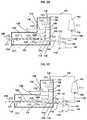
- FIG. 5Ais a perspective view of a sorbent manifold.
- FIG. 5Bis a view of a sorbent manifold showing fluid passageways.
- FIG. 5Cis a cross sectional view of a sorbent manifold.
- an elementmeans one element or over one element.
- ammonia concentrationor “ammonia level” refers to a total concentration of ammonia and/ammonium ions in a fluid, gas, or combinations thereof.
- ammonia is detectedcan refer to an ammonia concentration or level that exceeds a minimum detectable level of ammonia.
- the ammoniacan be detected by a sensor.
- ammonia sensorrefers to a device that performs all or part of a function to detect a level of, or measure a concentration of, ammonia and/or ammonium ions in a fluid, gas, or combinations thereof.
- bypassrefers to a flow path wherein a fluid, gas, or combinations thereof can pass around a certain component positioned in the flow path.
- a sorbent cartridgecan be bypassed such that fluid can avoid flowing through the sorbent cartridge and continue in the flow path.
- communicationrefers to any transfer of signs, signals, images, sounds, or data in whole or in part between two or more components by suitable means, such as by a wire, wirelessly, or a combination of both. Any method, component, device, or means known in the art can be used for the communication. Electronic communication can occur between a controller and a sensor and/or valve.
- a “conductivity sensor”is a device for measuring the electrical conductance of a solution and/or the ion, such as a sodium ion, concentration of a solution.
- a “controller”can refer to a device which monitors and affects the operational conditions of a given system, component, or device.
- the operational conditionsare typically referred to as output variables of the system wherein the output variables can be affected by adjusting certain input variables.
- controlcan refer to the ability of one component to direct the actions of a second component.
- a “control system”can be a combination of components acting together to maintain a system to a desired set of performance specifications.
- the control systemcan use processors, memory and computer components configured to interoperate to maintain the desired performance specifications.
- the control systemcan also include fluid or gas control components, and solute control components as known within the art to maintain the performance specifications.
- data from the one or more sensorsbroadly refers to any data obtained or derived from the measurements obtained from the one or more sensors. or any information related to the one or more sensors.
- dialysatedescribes a fluid into or out of which solutes from a fluid to be dialyzed diffuse through a membrane.
- An initial dialysate used for therapytypically contains electrolytes close in concentration to the physiological concentration of electrolytes found in blood. However, the concentration of the dialysate can change over the course of therapy, and can further be adjusted as desired.
- dialysate flow pathcan refer to a fluid pathway or passageway that conveys a fluid, such as dialysate and is configured to form at least part of a fluid circuit for peritoneal dialysis, hemodialysis, hemofiltration, hemodiafiltration or ultrafiltration.
- dialyzerrefers to a cartridge or container with two flow paths separated by semi-permeable membranes. One flow path is for blood and one flow path is for dialysate.
- dialyzercan refer to a cartridge or container with two flow paths separated by semi-permeable membranes. One flow path is for blood and one flow path is for dialysate.
- the membranescan be in hollow fibers, flat sheets, or spiral wound or other conventional forms known to those of skill in the art. Membranes can be selected from any one or combination of materials: polysulfone, polyethersulfone, poly (methyl methacrylate), modified cellulose, or other materials known to those skilled in the art.
- the membranescan be in hollow fibers, flat sheets, or spiral wound or other conventional forms known to those of skill in the art.
- Membranescan be selected from any one or combination of materials: polysulfone, polyethersulfone, poly (methyl methacrylate), modified cellulose, or other materials known to those skilled in the art
- dialyzer inletrefers to an inlet of a dialyzer for fluid to enter the dialyzer.
- dialyzer outletrefers to an outlet of the dialyzer for fluid to leave the dialyzer.
- Direct fluidrefers to an action during which a fluid is forced to flow towards a particular direction along a predetermined flow path.
- Directing fluidcan be controlled by one or more valves that can be set in opened or closed positions for particular flow directions of the fluid passing through the valves.
- selective directrefers to a fluid being directed to at least one particular direction out of two or more possible directions that the fluid can be directed.
- drain valverefers to a valve that can direct the flow of fluid by opening, closing or obstructing one or more pathways to allow the fluid to flow into a drain.
- drainlineor “drain line” refers to a fluid line or gas line through which a fluid, gas, or combinations thereof can flow into a drain.
- drain manifoldrefers to a component containing one or more fluid passageways and one or more components such as valves and sensors, where one or more valves are controlled by a controller based on measurements of the one or more sensors to direct fluid to either flow into a drain or pass around the drain.
- the drain manifoldcan be used as part of the dialysis system.
- the drain manifoldcan be combined with one or more other components of the dialysis system, such as a sorbent manifold, to form one integrated structure.
- downstreamrefers to a position of a first component in a flow path relative to a second component wherein fluid, gas, or combination thereof, can pass by the second component prior to the first component during normal operation.
- the first componentcan be said to be “downstream” of the second component, while the second component is “upstream” of the first component.
- fluidcan be any substance without a fixed shape that yields easily to external pressure such as a gas or a liquid.
- the fluidcan be water containing any solutes at any concentration.
- the fluidcan also be dialysate of any type including fresh, partially used, or spent.
- the fluidcan also contain one or more dissolved gas.
- fluidly connectablerefers to the ability to provide passage of fluid, gas, or combinations thereof, from one point to another point.
- the ability to provide such passagecan be any mechanical connection, fastening, or forming between two points to permit the flow of fluid, gas, or combinations thereof.
- the two pointscan be within or between any one or more of compartments, modules, systems, components, and rechargers, all of any type.
- fluidly connectedrefers to a particular state or configuration of one or more components such that fluid, gas, or combination thereof, can flow from one point to another point.
- the connection statecan also include an optional unconnected state or configuration, such that the two points are disconnected from each other to discontinue flow. It will be further understood that the two “fluidly connectable” points, as defined above, can from a “fluidly connected” state.
- the two pointscan be within or between any one or more of compartments, modules, systems, components, and rechargers, all of any type.
- a “fluid line”can refer to a tubing or conduit through which a fluid, gas, or fluid containing gas can pass.
- the fluid linecan also contain gas during different modes of operation such as cleaning or purging of a line.
- generating an alertor to “generate an alert” can refer to generating or signaling to a user a state or condition of a system.
- the term “alert”refers to any sign, text, voice, video, image or any indication of a state or a condition of a system. An alert can be given based on measurements of a sensor, for instances, when a pressure level of fluid exceeds a predetermined range, or an ammonia is detected in the fluid.
- outletcan refer to a portion of a component through which fluid and/or gas can be drawn into the component.
- the componentcan be a manifold.
- the term “in response to”refers to an action of responding to a condition
- the conditioncan be a measurement by a sensor, a signal transferred between two components, or an operating status of a component, such as open or close status of a valve.
- the term “in response to”can mean “based on” or “according to.”
- a controllercan react to certain signals received from a component positioned in another component or device, such as a sorbent manifold. Further, components in a sorbent manifold can react “in response to” signals sent from a controller.
- measuringcan refer to determining any parameter or variable.
- the parameter or variablecan relate to any state or value of a system, component, fluid, gas, or mixtures of one or more gases or fluids.
- measurementrefers to data or information of the parameter or variable determined.
- according to measurementsrefers to further calculation or operation that is proceeded based on or depending on the measurements.
- outletrefers to a portion of a component through which fluid or gas can be pulled out of the component in a fluid line, conduit, or fluid passageway of any type.
- the componentcan be a manifold.
- passagewayrefers to a fluid path through which fluid or gas can flow from one location to another location, where the passageway has walls to restrain the fluid or gas within the passageway and the walls at least in-part surround the fluid or gas and connect the two locations.
- pass throughrefers to an action of fluid or gas passing a component positioned in a flow path.
- the fluid or gascan enter an inlet of the component and exit via an outlet of the component to continue the flow path.
- transformrefers to a component, processor, algorithm, or method carrying out one or more actions.
- formedrefers to one or more actions that are carried out by the component, processor, algorithm, or method.
- the actionscan be set by instructions implemented by a component, processor, algorithm, or method of any type.
- predetermined rangeor “desired range” is any range of possible values for a parameter obtained in advance or a priori to actual use in a method.
- pressurerefers to a force exerted by a gas on the walls of a component, container, or conduit.
- pressure sensorcan refer to a device or any suitable component for measuring the pressure of a gas or fluid in a vessel, container, or fluid line.
- controllerwhen referring to a controller, can mean a series of instructions that cause a controller to perform certain steps.
- pumprefers to any device that causes the movement of fluids or gases by applying suction or pressure.
- pressing dialysateor to “pump dialysate” refer to moving dialysate through a flow path with a pump.
- Purified watercan be defined as water produced by distillation, deionization, reverse osmosis, or other suitable processes and that meets the definition of “purified water” in the United States Pharmacopeia, 23d Revision, Jan. 1, 1995, and the FDA at 21 CFR Section ⁇ 165.110(a)(2)(iv). Other criteria for purified water can be determined by those of skill in the art, particularly as relating to purified water suitable for dialysis.
- selectingor to “select” refers to choosing a variable or parameter from a set of possible variables or parameter.
- selective directingrefers to directing a fluid or gas to flow in at least one particular direction.
- the term “sensor”refers to a device, module, or system that can detect events or changes in its environment and indicate the information or send the information to other electronics, often a computer processor.
- the environmentcan be a fluid, gas, or a combination of fluid and gas.
- a sensormay detect changes of one or more fluid characteristics such as ammonia level, pressure, conductivity, and temperature.
- sorbent cartridgerefers to a cartridge containing one or more sorbent materials for removing specific solutes from solution, such as urea.
- the term “sorbent cartridge”does not require the contents in the cartridge to be sorbent based, and the contents of the sorbent cartridge can be any contents that can remove waste products from a dialysate.
- the sorbent cartridgemay include any suitable amount of one or more sorbent materials.
- the term “sorbent cartridge”can refer to a cartridge which includes one or more sorbent materials in addition to one or more other materials capable of removing waste products from a fluid such as dialysate.
- the term “sorbent cartridge”can also include configurations where at least one material in the cartridge does not act by mechanism of adsorption or absorption.
- sorbent dialysis systemrefers to a dialysis system containing one or more sorbent cartridges for removing impurities from fluid passing through the sorbent cartridges.
- the sorbent dialysis systemcan be used for regeneration of spent dialysate or obtaining purified water.
- sorbent inletrefers to an inlet of a component, such as a sorbent manifold, which can be fluidly connected to a dialysis flow system.
- the sorbent inletcan be fluidly connectable to an outlet of a sorbent cartridge in the dialysis flow system.
- sorbent linerefers to a fluid line that can connect to an inlet of a sorbent manifold and an outlet of a sorbent cartridge in a dialysis system.
- sorbent manifoldrefers to a component containing one or more fluid passageways and one or more components such as valves and sensors, where a controller can control one or more valves based on measurements of the one or more sensors to direct fluid to either pass through or bypass a sorbent cartridge in a dialysis system.
- the sorbent manifoldcan be used as part of the dialysis system.
- sorbent bypass moderefers to a sorbent manifold operating to selectively direct fluid that passes through the sorbent manifold to bypass a sorbent cartridge by controlling one or more valves based on measurements of one or more sensors in the sorbent manifold, the sorbent cartridge fluidly connectable to the sorbent manifold in a dialysis system.
- system drain moderefers to a sorbent manifold operating to drain fluid in a fluid line or passageway between a first valve and a second valve by controlling intermittently the first and second valve to selectively direct the fluid to flow away from the fluid line towards an outlet of the sorbent manifold.
- switching a valverefers to change the from a first position to a second position so that a fluid can be directed to a direction defined by the second position from a direction defined by the first position.
- the first position and second position of a valvecan be an opened position and a closed position.
- a “temperature sensor”is a sensor capable of determining the temperature of a fluid, gas, or combination thereof.
- treatment moderefers to a sorbent manifold operating to selectively direct fluid exiting the sorbent manifold to pass through a sorbent cartridge positioned downstream to the sorbent manifold in a flow path to continue the flow path.
- the fluidcan be dialysate in a dialysate flow path.
- Ultraseis an enzyme that catalyzes the conversion of urea into carbon dioxide and ammonium ions.
- upstreamrefers to a position of a first component in a flow path relative to a second component wherein fluid, gas, or combinations thereof, will pass by the first component prior to the second component during normal operation.
- the first componentcan be said to be “upstream” of the second component, while the second component is “downstream” of the first component.
- a “valve”can be a device capable of directing the flow of fluid or gas by opening, closing or obstructing one or more pathways to allow the fluid or gas to travel in a path.
- One or more valves configured to accomplish a desired flowcan be configured into a “valve assembly.”
- the sorbent manifolds of the inventioncan be used in integrated systems and methods for use in dialysis having one or more components such as valves and sensors and fluid passageways to direct fluid or gas to flow through a selective passageway from one location to another location within the sorbent manifold.
- the fluid or gascan be forced to enter and exit the sorbent manifold following one or more designated passageways.
- the compact structure of the sorbent manifoldavoids the need of complex tubing and can result in an enhanced and efficient control of fluid flow.
- Using a manifoldcan also make the dialysis system more compact and portable resulting in a dialysis machine that takes up less space and is easier to handle.
- the dialysis system containing a sorbent manifoldalso assists a patient or a non-professional technician to service the machine without the need for involved and sophisticated training.
- the sorbent manifoldscan be made of plastic using well-known techniques, and thus reduce overall manufacturing cost.
- FIG. 1is a portion of a dialysate flow path including a sorbent manifold 101 in a sorbent dialysis system.
- a dialysate flow pathis a fluid pathway or passageway that conveys a fluid, such as dialysate and is configured to form at least part of a fluid circuit for peritoneal dialysis, hemodialysis, hemofiltration, hemodiafiltration or ultrafiltration.
- the sorbent manifold 101can be fluidly connected to the dialysate flow path at a position upstream of a sorbent cartridge 111 , wherein fluid, gas, or combinations thereof, can bypass the sorbent manifold 101 prior to the sorbent cartridge 111 during dialysis.
- the sorbent cartridge 111can be positioned at a position downstream of the sorbent manifold 101 .
- the sorbent cartridge 111can be a cartridge containing one or more sorbent materials for removing specific solutes from solution, such as urea.
- the dialysis system containing one or more sorbent cartridges for removing impurities from fluid passing through the sorbent cartridgescan be used for regenerating spent dialysate or obtaining purified water.
- the sorbent manifold 101can selectively direct fluid to either pass through or bypass the sorbent cartridge 111 .
- the sorbent manifold 101can direct a fluid or gas entering the sorbent manifold 101 to selectively flow through one or more direction towards a specified outlet of the sorbent manifold 101 .
- spent dialysatecan pass around the sorbent cartridge 111 to continue the flow path.
- the fluid or gascan also enter an inlet 132 of the sorbent cartridge 111 , pass through one or more sorbent materials in the sorbent cartridge 111 , and exit via an outlet 131 of the sorbent cartridge 111 to continue the flow path.
- the sorbent cartridge 111can be used to obtain purified water.
- Purified watercan be defined as water produced by distillation, deionization, reverse osmosis, or other suitable processes and that meets the definition of “purified water” in the United States Pharmacopeia, 23d Revision, Jan. 1, 1995, and the FDA at 21 CFR Section ⁇ 165.110(a)(2)(iv). Other criteria for purified water can be determined by those of skill in the art, particularly as relating to purified water suitable for dialysis.
- the sorbent manifold 101can comprise a plurality of passageways fluidly connectable to one or more valves and one or more sensors in a sorbent dialysis system, wherein the sorbent manifold 101 controls the one or more valves to direct fluid to either pass through a sorbent cartridge 111 in the sorbent dialysis system or bypass the sorbent cartridge 111 based on measurements obtained from one or more sensors.
- the sorbent manifold 101can direct an action in one or more valves to direct fluid by controlling the one or more valves in an opened or closed position.
- the sorbent manifold 101can include components such as valves and sensors positioned to one or more of a first, second, and third parts.
- the valvecan direct the flow of fluid or gas by opening, closing or obstructing one or more pathways to allow the fluid or gas to travel in a specified flow path.
- One or more valves configured to accomplish a desired flowcan be configured into a valve assembly.
- the sensorcan be any device, module, or system of components that can be used to detect events or changes in the sorbent manifold and send the information to other electronics, such as a computer processor or specific purpose computer.
- the sensorcan detect changes of one or more fluid characteristics such as ammonia level, pressure, conductivity, and temperature.
- the valves and sensorscan also be removable when the first, second, and third parts are disassembled.
- the sorbent manifold 101can be formed from any suitable material such as plastic, metal, or composites.
- the sorbent manifold 101can be fluidly connected to the dialysate flow path through ports or connectors attached to one or more of the first, second, and third parts.
- the sorbent cartridge 111can include one or more layers of sorbent materials.
- the sorbent cartridge 111can include aluminum oxide for removal of fluoride and heavy metals, activated carbon that operates to adsorb non-ionic molecules, organic molecules, and chlorine from the water, along with some endotoxins or bacterial contaminants.
- the sorbent cartridge 111can also include other components that work primarily by physical and chemical adsorption, combined with one or more ion exchange materials.
- the sorbent cartridge 111can contain urease, which catalyzes the conversion of urea to ammonium ions and carbon dioxide.
- the sorbent cartridge 111can additionally include a microbial filter and/or a particulate filter.
- a microbial filtercan further reduce an amount of bacterial contaminants present in the fluid.
- the sorbent cartridge 111can be used to obtain regenerated dialysate from the spent dialysate for reuse in the dialysis system.
- the sorbent cartridge 111may also be used to generate purified water by removing contaminants from a water source.
- the sorbent manifold 101can selectively direct fluid to either pass through the sorbent cartridge 111 or bypass the sorbent cartridge 111 .
- the sorbent manifold 101is capable of directing the fluid to enter an inlet 132 of the sorbent cartridge 111 and exit the sorbent cartridge 111 via an outlet 131 of the sorbent cartridge 111 .
- the sorbent manifold 101can also direct fluid to pass around the sorbent cartridge 111 during ammonia breakthrough or if dialysate pressure exceeds a predetermined range.
- the sorbent manifold 101can direct the fluid to flow into a particular direction or multiple directions as needed.
- the sorbent manifold 101can have one or more inlets and one or more outlets through which fluid can enter or exit the sorbent manifold 101 .
- An inlet of the sorbent manifold 101can be a portion of the sorbent manifold 101 through which fluid and/or gas can be drawn into the sorbent manifold 101 .
- An outlet of the sorbent manifold 101can be a portion of the sorbent manifold 101 through which fluid or gas can be pulled out of the sorbent manifold 101 in a fluid line, conduit, or fluid passageway of any type.
- the sorbent manifold 101can have at least a first inlet 102 and a second inlet 103 .
- the sorbent manifold 101can have at least a first outlet 104 and a second outlet 105 .
- the first inlet 102 , the second inlet 103 , the first outlet 104 , and the second outlet 105are not limited to any particular places of the sorbent manifold 101 .
- the inlets and outlets of the sorbent manifold 101can also be configured at positions that facilitate the formation of passageways to enable fluid communication to the dialysate flow path.
- the first and second inlets 102 , 103 and first and second outlets 104 , 105 of the sorbent manifold 101may each be an opening at the main body of the sorbent manifold 101 , where the first to fourth passageways 113 , 114 , 115 , and 116 are fluidly connectable to corresponding parts of the dialysate flow path through the openings.
- the openingscan be formed by connectors 117 , 119 , 121 , and 118 , each having one part attached to the sorbent manifold 101 and a complimentary part attached to the dialysate flow path.
- Connectors 117 , 119 , 121 , and 118can also form fluid connections to the dialysate flow path without their respective complimentary parts.
- Such connectorsprovide structural features for the sorbent manifold 101 to be fluidly connectable to the dialysate flow path.
- Connectors 117 , 119 , 121 , and 118can be fastened onto the sorbent manifold 101 and corresponding parts of the main dialysis flow system.
- the sorbent manifold 101can also be connected to the main dialysis system by any one or more of twisting, snapping, plugging, matching protrusions/indents of corresponding structures. Any structural component, means, or method can be applied to connect the sorbent manifold 101 to a main dialysis system
- the first inlet 102can be formed by connector 117
- the first outlet 104can be formed by connector 119
- the second inlet 103can be formed by connector 121
- the second outlet 105can be formed by connector 118 .
- the connectors 117 , 118 , 119 , and 121can provide for the passage of fluid, gas, or a combination thereof, from one point to another point.
- the two pointscan be within or between any one or more of compartments, modules, systems, components, and rechargers, all of any type.
- the connectioncan optionally be disconnected and then reconnected.
- the sorbent manifold 101includes a plurality of passageways formed by the fluid entering the sorbent manifold 101 .
- a pump(not shown) can provide a driving force to move fluid through the sorbent manifold 101 .
- the pumpmay be located at a position in the dialysate flow path upstream to the sorbent manifold 101 .
- the pumpmay also be located at a position in the dialysate flow path downstream to the sorbent manifold 101 .
- the pumpmay also be placed in the sorbent manifold 101 .
- the first passageway 113 in the sorbent manifold 101fluidly connects the first inlet 102 to the first valve 110 .
- the first inlet 102fluidly connects to a fluid line 136 to receive fluid entering the sorbent manifold 101 .
- the first passageway 113fluidly connects to the first valve 110 via a port 122 .
- One or more sensorscan be selected from a group of sensors consisting of ammonia sensor 106 , pressure sensor 107 , temperature sensor 108 and conductivity sensor 109 , which can be positioned on the first passageway 113 in series to each other.
- a fluid line 137can be included as part of the first passageway 113 to fluidly connect the pressure sensor 107 to the other sensors including one or more of the ammonia sensor 106 , temperature sensor 108 , and conductivity sensor 109 .
- a fluid line 140can be fluidly connectable to temperature sensor 108 and conductivity sensor 109 as shown in FIG. 2D .
- Ammonia sensor 106is a device measuring a level of ammonia in the fluid passing by the ammonia sensor 106 .
- the dialysatecan flow through or across the ammonia sensor 106 that detects a potentially hazardous condition where the ammonia byproduct of urea breakdown escapes from sorbent cartridge 111 .
- the ammonia sensor 106may use optical methods to detect a color change of ammonia and/or ammonium sensitive media contained within ammonia sensor 106 .
- the pressure sensor 107measures the pressure of a gas or fluid in the sorbent manifold 101 . If ammonia and/or ammonium are detected, and/or if a pressure level higher than the desired range is detected, control action switches one or more of a first valve 110 and second valve 120 to direct dialysate to bypass the sorbent cartridge 111 through passageway 115 .
- the control action of switching valvesis performed by a controller 200 (shown in FIG. 2D ) of the sorbent manifold 101 .
- the temperature sensor 108measures the temperature of a fluid or gas, or a combination thereof in the sorbent manifold 101
- the conductivity sensor 109measures the electrical conductance of a solution and/or the ion, such as a sodium ion, concentration of a solution.
- the conductivity sensor 109can have two electronic heads 109 a and 109 b.
- the first valve 110can be positioned at downstream of the one or more sensors selected from the group of sensors consisting of ammonia sensor 106 , pressure sensor 107 , temperature sensor 108 and conductivity sensor 109 .
- the first valve 110can be a three-way valve with each way attached to a connector fluidly connectable to the first passageway 113 via a port 122 , the second passageway 114 via a port 124 , and the third passage way 115 via a port 123 .
- the second passageway 114fluidly connects the first valve 110 to the first outlet 104 of the sorbent manifold 101 . Fluid exiting the first outlet 104 flows into an inlet 132 of the sorbent cartridge 111 .
- the first outlet 104 of the sorbent manifold 101is fluidly connectable to the sorbent cartridge 111 .
- a third valvesuch as a drain valve 130 , can be placed at a position in the dialysate flow path downstream to the first outlet 104 of the sorbent manifold 101 and upstream to the inlet 132 of the sorbent cartridge 111 .
- a drain valve 130is a valve that can direct the flow of fluid by opening, closing or obstructing one or more pathways to allow the fluid to flow into a drain 112 during priming, disinfection, or draining of the system.
- fluid exiting the first outlet 104 of the sorbent manifold 101may first reach the drain valve 130 via a port 125 and then exit the drain valve 130 via a port 126 to flow towards the inlet 132 of the sorbent cartridge 111 along a fluid line 133 .
- the drain valve 130can selectively direct the fluid exiting the first outlet 104 of the sorbent manifold 101 to a drain 112 via a connector 127 and a fluid line 134 .
- the third passageway 115 of the sorbent manifold 101fluidly connects the first valve 110 at port 123 and the second valve 120 at port 128 .
- the first valve 110can selectively direct fluid into a fluid line 139 to exit the sorbent manifold 101 via a second outlet 105 .
- the fluid line 139can be a part of the third passageway 115 . Fluid exiting the second outlet 105 via connector 118 enters the dialysate flow path at a position downstream to the sorbent manifold 101 .
- the fourth passageway 116fluidly connects the second valve 120 to a second inlet 103 of the sorbent manifold 101 .
- the second inlet 103is fluidly connectable to an outlet 131 of the sorbent cartridge 111 .
- the second inlet 103 and the first outlet 104 of the sorbent manifold 101can be fluidly connectable to each other through the sorbent cartridge 111 .
- Fluid exiting the first outlet 104 of the sorbent manifold 101can enter the sorbent cartridge 111 via fluid line 133 fluidly connectable to the sorbent cartridge inlet 132 and exit the sorbent cartridge 111 to enter the second inlet 103 of the sorbent manifold 101 via fluid line 135 fluidly connectable to the sorbent cartridge outlet 131 .
- the second inlet 103 of the sorbent manifold 101can be a sorbent inlet, which is fluidly connectable to a sorbent line that receives fluid exiting from the sorbent cartridge 111 .
- the second inlet 103is formed by connector 121 fluidly connectable to the fourth passageway 116 , which is fluidly connectable to the second valve 120 via port 138 .
- the second valve 120is fluidly connectable to the first valve 110 via port 128 attached to the second valve 120 and port 123 attached to the first valve 110 .
- the second valve 120 and first valve 110is fluid connectable to each other via fluid line 139 , which is part of the third passageway 115 .
- Port 128 attached to the second valve 120is fluidly connectable to connector 129 , which is attached to the third passageway 115 .
- the second valve 120can be a two-way valve, three-way valve, or four-way valve, as understood by a person of ordinary skill in the art.
- the sorbent manifold 101can contain one or more valves positioned therein as a valve assembly or separate valves.
- the valvescan be a device capable of directing the flow of fluid or gas by opening, closing or obstructing one or more pathways to allow the fluid or gas to travel in a path.
- One or more valves configured to accomplish a desired flowcan be configured into a valve assembly.
- the one or more valves in the sorbent manifold 101are fluidly connectable to the dialysate flow path.
- the sorbent manifold 101can have a first valve 110 and a second valve 120 . Additional valves may also be placed in the sorbent manifold 101 .
- the one or more valvesmay be attached or fixed to the sorbent manifold 101 .
- the one or more valvesmay become one or more integrated parts of the sorbent manifold 101 .
- the one or more valvesmay be welded to the sorbent manifold 101 using known approaches in the art.
- the one or more valvesmay also be removably attached to the sorbent manifold 101 , and the sorbent manifold 101 may be shaped properly to receive the valves.
- the sorbent manifold 101can be shaped as a capital letter “L” in either direction. As shown in FIGS. 1 and 2 , the sorbent manifold 101 is shaped as a reversed letter “L” with a second valve 120 positioned close to an intersection of the two perpendicular parts.
- the sorbent manifold 101is not limited to a particular shape.
- the sorbent manifold 101may contain a groove complimentary to the shapes of the valves so that the valves may be attached steadily to the sorbent manifold 101 .
- the one or more valvesmay be placed in different positions within the sorbent manifold 101 .
- a valvesuch as the first valve 110 or the second valve 120 , may be fixed to any one of a bottom surface, a side surface, or a top surface of the sorbent manifold 101 .
- the first valve 110may be a three-way valve and second valve 120 may be a two-way valve as shown in FIG. 1 , however, the first valve 110 and the second valve 120 are not limited to a particular type of valve.
- the first valve 110 and the second valve 120may be combined as a valve assembly and may also be separately positioned without physically contacting each other.
- the first valve 110 and second valve 120may each contain a set of individual valves that can work coordinately to achieve the desired purposes.
- a person of skillwould understand that any suitable type or structure of the one or more valves can be used in the sorbent manifold 101 . Further, the valves can be fluidly connected to each other and to the dialysate flow path.
- the sorbent manifold 101can comprise a first valve 110 fluidly connecting a first passageway 113 to a second passageway 114 , the first passageway 113 fluidly connectable to a first inlet 102 of the sorbent manifold 101 and the second passageway 114 fluidly connectable to a first outlet 104 of the sorbent manifold 101 .
- the first outlet 104 of the sorbent manifold 101can be fluidly connectable to an inlet 132 of the sorbent cartridge 111 via valve 130 external to the sorbent manifold 101 ; second valve 120 inside the sorbent manifold 101 via valve 110 fluidly connecting a third passageway 115 to a fourth passageway 116 , the third passageway 115 fluidly connectable to a second outlet 105 of the sorbent manifold 101 via valve 120 .
- the fourth passageway 116can be fluidly connectable to a second inlet 103 of the sorbent manifold 101 wherein the second inlet 103 can be fluidly connectable to an outlet 131 of the sorbent cartridge 111 .
- the second inlet 103can be fluidly connectable to a sorbent line that receives fluid obtained from the sorbent cartridge 111 .
- the first valve 110can be positioned between the first passage way 113 and second passageway 114 to fluidly connect the first passageway 113 to the second passageway 114 .
- Spent dialysatecan be passed from the first inlet 102 to the first passageway 113 , the first valve 110 , the second passageway 114 , and exit the sorbent manifold 101 via the first outlet 104 .
- Spent dialysate exiting the sorbent manifold 101can then be directed to pass through the sorbent cartridge 111 and become regenerated after removal of impurities by sorbent materials in the sorbent cartridge 111 .
- the regenerated dialysatecan enter the sorbent manifold 101 via the second inlet 103 of the sorbent manifold 101 , and exit the sorbent manifold 101 via the second outlet 105 of the sorbent manifold 101 to join the main dialysate flow path.
- the sorbent manifold 101further contains one or more sensors of an ammonia sensor 106 , a pressure sensor 107 , a temperature sensor 108 , and a conductivity sensor 109 .
- the ammonia sensor 106measures a concentration of ammonia and/or ammonium as an ammonia level in the fluid. Additional sensors can also be placed in sorbent manifold 101 , a device for measuring a level of ammonia in the environment.
- any suitable sensor as described hereincan be included in the sorbent manifold 101 .
- the sorbent manifold 101can comprise one or more sensors selected from a group consisting of the ammonia sensor 106 , temperature sensor 108 , conductivity sensor 109 , and pressure sensor 107 . Fluid can be directed to flow through the first inlet 102 , one or more of ammonia sensor 106 , pressure sensor 107 , temperature sensor 108 , and conductivity sensor 109 to reach the first valve 110 .
- the one or more sensorscan be placed in a position upstream of the first valve 110 , but are not limited to a specific position or in a specific order in the sorbent manifold 101 .
- the position of the one or more sensors in the flow pathcan be upstream relative to the one or more valves in the sorbent manifold 101 , wherein fluid, gas, or combinations thereof, can flow through the one or more sensors of ammonia sensor 106 , pressure sensor 107 , temperature sensor 108 , and conductivity sensor 109 prior to the first valve 110 during normal operation for dialysis therapy or during priming.
- the one or more sensorscan be used to ensure that the fluid such as dialysate or priming fluid in the flow path is within a proper range of one or more detected fluid characteristic.
- the pressure sensor 107measures pressure of dialysate in the sorbent manifold 101 before an inlet of the sorbent cartridge 111 . If the pressure is too high, the dialysate can be directed in the flow path to bypass the sorbent cartridge 111 .
- the temperature sensor 108measures a temperature of the dialysate.
- the conductivity sensor 109measures the electrical conductance of the dialysate and/or the ion, such as a sodium ion, concentration of the dialysate.
- the pressure sensor 107 , temperature sensor 108 , and conductivity sensor 109 in the sorbent manifold 101can be used to ensure that the dialysate in the dialysate flow path is within a proper range of pressure, temperature, and conductivity, respectively.
- the sorbent manifold 101may also include an additional or alternative sensor to detect some or different fluid characteristics of the fluid passing through the sorbent manifold 101 .
- Drain valve 130 located at a position downstream of the first valve 110can optionally be included either within or outside of the sorbent manifold 101 .
- the drain valve 130can fluidly connect the first valve 110 to the inlet of the sorbent cartridge 111 .
- the drain valve 130can selectively direct the fluid to a drain 112 rather than directing fluid towards the sorbent cartridge 111 during draining of the system.
- the drain valve 130can be placed in a drain manifold (not shown) separated from the sorbent manifold 101 .
- the drain valve 130can also be placed within the sorbent manifold 101 .
- the drain valve 130 of the sorbent manifold 101is capable of directing the fluid to a drain 112 and is also capable of directing the fluid to flow to sorbent cartridge 111 without flowing into drain 112 .
- the drain valve 130can selectively direct the flow of fluid by opening, closing or obstructing one or more pathways to allow the fluid to flow into drain 112 .
- the first valve 110 , second valve 120 , and drain valve 130can be controlled by a controller 200 , as shown in FIG. 2D .
- a controller 200is a device, processor, logic, circuit, or programmable computer which monitors and affects the operational conditions of a given system based on the one or more sensors.
- the controller 200can open and close the described valves to direct flow inside and through the sorbent manifold 101 .
- the operational conditionsare typically referred to as output variables of the system wherein the output variables can be affected by adjusting certain input variables.
- the controller 200can direct actions of a functional component, such as the one or more sensors and valves via signals transferred between the controller 200 and the functional component.
- the controller 200can communicate with the valves and sensors by receiving from and sending signals to the valves and sensors.
- the controller 200can direct the actions of one or more valves of the first valve 110 , second valve 120 , and drain valve 130 based on measurements obtained from one or more sensors of the ammonia sensor 106 , pressure sensor 107 , temperature sensor 108 , and conductivity sensor 109 .
- Other functional components in the sorbent manifold 101can be electronically connected to each other and to the controller 200 by wire, or wirelessly, or a combination thereof.
- the controller 200can collect measurements from the pressure sensor 107 , determine whether a pressure level of the dialysate passing through the sorbent manifold 101 is within a desired range. If a pressure level of the dialysate exceeds a desired range, the controller 200 controls one or more of the first valve 110 and the second valve 120 to selectively direct the fluid to bypass the sorbent cartridge 111 through passageway 115 when the controller 200 determines that the pressure level exceeds a desired range. If the pressure level of the dialysate in the sorbent manifold 101 is within the desired range, the controller 200 controls one or more of the first valve 110 and second valve 120 to selectively direct the fluid to one of the fluid paths shown in FIGS. 2A-2B as needed.
- the controller 200can direct any one or more of valves 110 or 120 to selectively direct a fluid to bypass the sorbent cartridge 111 when ammonia breakthrough occurs, or if the fluid pressure is above a predetermined range.
- the sorbent manifold 101provides a protective mechanism to prevent patient harm due to high pressure or ammonia breakthrough.
- the sorbent manifold 101can comprise a controller 200 (shown in FIG. 2D ) in electronic communication with the first valve 110 and the second valve 120 ; the controller 200 controlling the first valve 110 and second valve 120 to direct the fluid from one of the first inlet 102 and second inlet 103 to one of the first outlet 104 and second outlet 105 of the sorbent manifold 101 .
- a controller 200shown in FIG. 2D
- the controller 200controlling the first valve 110 and second valve 120 to direct the fluid from one of the first inlet 102 and second inlet 103 to one of the first outlet 104 and second outlet 105 of the sorbent manifold 101 .
- signs, signals, images, sounds, or any data in whole or in partare transferred between the controller 200 and one or more of the first valve 110 and second valve 120 by a wire or wirelessly, or a combination thereof.
- Any proper meanscan be used for the controller 200 to communicate with any one or more of the first valve 110 and the second valve 120 .
- the sorbent manifold 101can be made of biocompatible materials and can be in any shape suitable to be positioned in the dialysate flow path.
- the sorbent manifold 101can be shaped to contain any one or more of the first valve 110 , second valve 120 , and drain valve 130 , and one or more of the ammonia sensor 106 , pressure sensor 107 , temperature sensor 108 , and conductivity sensor 109 , and other internal structures, which may include a pump or a heater (not shown in FIG. 1 ).
- the sorbent manifoldcan be formed from molded materials such that the valves are comprised of grooves or channels formed inside the manifold.
- the valvecan be incorporated as part of the structure of the sorbent manifold and the passageways formed as channels inside the sorbent manifold.
- Materials used for making the sorbent manifold 101can be selected from a group comprising ABS, Lustran, and other similar products proper in the art.
- the sorbent manifold 101can be produced using a standard injection molding grade based on a MABS polymer with a well-balanced stiffness, toughness, and high transparency.
- the materialscan be compatible with dialysate and can optionally have sufficient transparency to allow a user to examine passageways and other internal structures contained in the sorbent manifold 101 .
- the sorbent manifoldcan have compatibility for manufacturing processes such as adhesion or welding.
- the sorbent manifold 101can contain one or more fluid passageways and one or more components such as valves and sensors formed as grooves and channels into a sorbent manifold (not shown).
- a fluid passageway or channel formed integral to the body of the sorbent manifoldprovide flow from one location to another location, where the passageway or channels has walls to restrain the fluid or gas within the passageway or channel such that the walls at least in-part surround the fluid or gas and connect the two locations.
- the sorbent manifold 101can have different plastic parts assembled together to form an integrated structure, with a plurality of functional components glued onto the plastic parts inside the sorbent manifold 101 .
- the functional componentssuch as one or more of the first valve 110 , second valve 120 , drain valve 130 and one or more of the ammonia sensor 106 , pressure sensor 107 , temperature sensor 108 , and conductivity sensor 109 , can also be twisted, snapped, or plugged onto the plastic parts inside the sorbent manifold 101 .
- the sorbent manifold 101can have a first part, a second part, and a third part, which can be attached together in series to form an integrated structure.
- the first part, second part and third partmay be removable or permanently connected to a different part of the sorbent manifold 101 .
- the sorbent manifold 101is not limited to having a particular number of different parts to form the integrated structure.
- the sorbent manifold 101can contain a part that can be opened to access internal structures of the sorbent manifold 101 .
- One or more parts of the sorbent manifold 101may be reversibly sealed to a different part of the sorbent manifold 101 .
- Different parts of the sorbent manifold 101can be put together using any suitable means, such as ultrasonic welding, laser welding, or adhesion.
- the first, second, and third partscan be affixed together using any proper means known in the art. Fluid passageways or internal channels may be completed after the parts being properly positioned together to form the sorbent manifold 101 .
- One part of the sorbent manifold 101can have a size same or different as that of a different part of the sorbent manifold 101 .
- the sorbent manifold 101can be produced using a standard injection molding grade based on a MABS polymer, such as Terlux HD 2802 and Terlux HD 2822, which offers a well-balanced stiffness, toughness, and high transparency, as known in the art.
- the sensors and the valves or other internal structurescan be fixed or attached to the sorbent manifold 101 using techniques suitable to a person of skill in the art.
- the sensors and the valvescan be welded to the main body of the sorbent manifold 101 .
- the first through fourth passageways 113 , 114 , 115 , and 116can be formed by the lid and main body using ultrasonic or laser welding.
- the main body of the sorbent manifold 101can be formed via the use of an energy director.
- the energy directorcan be a bead of material molded on the joint surface primarily used to concentrate energy to rapidly initiate the softening and melting of the joint surface.
- the basic energy designmay be incorporated into other joint configurations such as shear joints, step joint, tongue and groove.
- FIGS. 2A-Cshow pathways in a sorbent manifold 101 .
- FIG. 2Aillustrates the fluid paths during a treatment mode.
- the flow path as shown in light grayrefers to a valve and flow state in which the sorbent manifold 101 operates to selectively direct fluid exiting the sorbent manifold 101 to pass through a sorbent cartridge 111 positioned downstream to the sorbent manifold 101 and out second outlet 105 .
- the fluidcan be dialysate in a dialysate flow path.
- FIG. 2Billustrates fluid paths during a sorbent bypass mode in a gray highlighted pathway that selectively directs fluid to pass through the sorbent manifold 101 to bypass a sorbent cartridge 111 .
- the controller 200 of FIG. 2Dcan control one or more valves based on measurements of one or more sensors in the sorbent manifold 101 .
- FIG. 2Cillustrates the fluid paths in gray during a system drain mode. The highlighted paths in gray FIGS. 2A-2C indicate activated passageways based on status of the valves as controlled by a controller 200 as shown in FIG. 2D .
- FIG. 2Dis a perspective view of a sorbent manifold 101 including the controller 200 that controls the valves and other components of the sorbent manifold 101 .
- An outline 141 of the sorbent manifold 101is illustrated in FIG. 2D .
- first valve 110can be activated and set to a first state such that fluid entering the sorbent manifold 101 through the first inlet 102 can be directed to the first outlet 104 of the sorbent manifold 101 via the first passageway 113 and the second passageway 114 towards an inlet of the sorbent cartridge 111 , as shown in FIG. 2A .
- the first valve 110fluidly connects the first passageway 113 and the second passageway 114 .
- the first valve 110 and the second valve 120can be set in the first state that allows the fluid in passageway 113 to flow into the passageway 114 without being diverted towards the second valve 120 .
- Spent dialysate exiting the sorbent manifold 101can enter the sorbent cartridge 111 inlet, pass through the sorbent materials contained in the sorbent cartridge 111 , and exit the sorbent cartridge 111 through outlet 131 .
- impurities and toxins in the spent dialysatecan be removed by the one or more sorbent materials in the sorbent cartridge 111 .
- Regenerated dialysate obtained from the sorbent cartridge 111can enter the dialysate flow path for use.
- watercan enter the sorbent manifold 101 and flow along the passageways 113 and 114 controlled by the first valve 110 and second valve 120 .
- controller 200can collect measurements from the ammonia sensor 106 , pressure sensor 107 , temperature sensor 108 , and conductivity sensor 109 to determine if the measurements are within a desired range. If the measurements from the above sensors are within the desired range, the controller 200 controls the first valve 110 and second valve 120 to continue the treatment mode assuming there are no other adverse signals detected. If the measurements from the above sensors are beyond the desired range, the controller 200 controls the first valve 110 and second valve 120 to switch from the treatment mode to the bypass mode.
- the first valve 110can be activated and set to a second state and the second valve 120 can set to a second state.
- the first valve 110 and second valve 120can selectively direct the fluid entering the first inlet 102 of the sorbent manifold 101 to enter the passageway 115 towards the second outlet 105 of the sorbent manifold 101 .
- the fluidcan then exit the sorbent manifold 101 via the second outlet 105 .
- the sorbent manifold 101can form a flow path connecting the first inlet 102 , the first passageway 113 , the first valve 110 , and a portion of the fluid line between the first valve 110 and the second valve 120 , the passageway 115 , and the second outlet 105 .
- the bypass modecan be triggered if measurements of an ammonia level or pressure level are outside a predetermined range.
- the measurementscan be obtained from one or more sensors including an ammonia sensor 106 , a pressure sensor 107 , a temperature sensor 108 , and a conductivity sensor 109 .
- the sorbent manifold 101can also generate an alert to warn a user that the ammonia is detected in the dialysate or the ammonia level exceeds the desired range based on measurements from the ammonia sensor 106 .
- the alertcan be any signs, texts, or sounds or a combination thereof.
- Dialysatecan be directed from passageway 113 to passageway 115 when valve 110 is in the normally closed state from port 122 to port 123 .
- the described valve arrangementcan be referred to as sorbent bypass or a sorbent bypass mode. Sorbent bypass can be initiated when the pressure exceeds a predetermined threshold or range, such as equal to or greater than about 2,500 mmHg. The sorbent bypass mode can also be initiated during system fluid priming.
- FIG. 2Cillustrates the fluid passageways in the sorbent manifold 101 fluidly connected to a drain 112 .
- the sorbent manifold 101can have a drain valve 130 in addition to the first valve 110 and the second valve 120 .
- the drain valve 130can be positioned external to the sorbent manifold 101 as a component of a drain manifold (not shown).
- the drain manifold and the sorbent manifold 101can be combined as one compact structure or separated as two different manifolds. In either configuration, the drain valve 130 can be controlled by a controller 200 ( FIG. 2D ) to selectively direct the fluid passing through the sorbent manifold 101 to flow to a drain 112 .
- the sorbent manifold 101can selectively direct the fluid to a drain 112 to drain fluid out of the system, such as after disinfection.
- the first valve 110can be a sorbent bypass valve (SBV) and the second valve 120 can be a sorbent isolation valve (SIV) in FIGS. 2A-2D .
- SBVsorbent bypass valve
- SIVsorbent isolation valve
- the first valve 110 and the second valve 120can be any suitable valves.
- the first valve 110 and the second valve 120can be 2-way or 3-way valves, or a valve assembly containing multiple valves.
- valves 110 and 120can be in a specified state to selectively direct fluid through a particular flow path or passageway.
- port 122can be connected to port 124
- port 125can be connected to port 126
- port 138can be connected to port 128 , selectively directing fluid through the sorbent cartridge 111 .
- port 122can be connected to port 123 and port 138 is not connected to port 128 , selectively directing fluid through a sorbent bypass pathway.
- port 122can be connected to port 124 and port 125 can be connected to port 127 to selectively direct fluid to a drain 112 .
- FIG. 2Dis a perspective view of the sorbent manifold 101 containing a controller 200 , the first valve 110 (SBV) and second valve 120 (SIV), one or more of sensors including ammonia sensor 106 , pressure sensor 107 , temperature sensor 108 , and conductivity sensor 109 , and the passageways 113 , 114 , 115 , and 116 .
- the controller 200can contain a processor that receives data from one or more of the sensors including the pressure sensor 107 , temperature sensor 108 and conductivity sensor 109 . In response to the measurement from the one or more sensors, the controller 200 can determine whether or not to activate any one or more of the first valve 110 and the second valve 120 .
- the controller 200may further determine which state the valves should be set based on the measurements from the one or more sensors. Once a determination is made, the controller 200 can send signals to any one or more of the first valve 110 and the second valve 120 to control opening and closing status of the valves.
- the sorbent manifold 101can comprise a controller 200 in communication with the first valve 110 and the second valve 120 ; the controller 200 controlling the first valve 110 and second valve 120 to selectively direct the fluid from the first inlet 102 or second inlet 103 to the first outlet 104 or second outlet 105 following the fluid passageways illustrated in FIGS. 2A-2C .
- An inlet of the sorbent manifold 101is a portion of the sorbent manifold 101 through which fluid and/or gas can be drawn into the sorbent manifold 101 .
- An outlet of the sorbent manifold 101can be a portion of the sorbent manifold 101 through which fluid or gas can be pulled out of the sorbent manifold 101 in a fluid line, conduit, or fluid passageway of any type.
- the sorbent manifold 101can comprise the controller 200 which can be programmed to selectively direct the fluid from the first inlet 102 to either the first outlet 104 or to the second outlet 105 based on data from the one or more sensors including pressure sensor 107 , temperature sensor 108 , and conductivity sensor 109 .
- the controller 200 that has been programmedcan perform particular steps according to a series of instructions defined by one or more programs.
- the controller 200can communicate with any one or more of the sensors and valves via signal transferring therebetween.
- the sensorscan include the ammonia sensor 106 , pressure sensor 107 , temperature sensor 108 , conductivity sensor 109 , and additional sensors as needed.
- the valvescan include the first valve 110 , second valve 120 , and additional valves such as the drain valve 130 .
- the signalscan be texts, images, sounds, or any data in whole or in-part transferred between the two components via any proper means, such as by a wire or wirelessly, or a combination thereof.
- the sorbent manifold 101can be a component containing one or more fluid passageways and one or more components such as valves and sensors, where one or more valves are controlled by a controller 200 based on measurements of the one or more sensors to direct fluid to either pass through or bypass a sorbent cartridge 111 in a dialysis system.
- the sorbent manifold 101can be used as part of a sorbent dialysis system.
- a sorbent dialysis systemcontains one or more sorbent cartridges 111 containing one or more sorbent materials for removing impurities, such as urea, from fluid that passes through the sorbent cartridges 111 .
- the sorbent dialysis systemcan be used for regeneration of spent dialysate or obtaining purified water.
- the use of the sorbent manifold 101can include steps of initiating a dialysis session, pumping the fluid to pass through the sorbent manifold 101 as shown in FIG. 2A , by a pump (not shown) measuring pressure and/or measuring ammonia of the fluid, and if the pressure and/or ammonia level is within a desired range, the fluid will be continued along the flow path shown in FIG. 2A .
- the fluidcan be dialysate.
- the dialysatecan flow from the first passageway 113 to second passageway 114 , optionally flow through a drain valve 130 , pass through the sorbent cartridge 111 by flowing from an inlet to an outlet of the sorbent cartridge 111 , and enter the sorbent manifold 101 through the second inlet 103 towards the second outlet 105 via the second valve 120 and the third passageway 115 to join the dialysate flow path. If any one or more of the pressure and ammonia level of the fluid is beyond the desired range, the fluid would be directed to bypass the sorbent cartridge 111 . If ammonia breakthrough or any other hazardous condition occurs, the dialysate can be directed to bypass the sorbent cartridge 111 to continue the flow path.
- the sorbent manifold 101can comprise the at least one sensor including a pressure sensor 107 and wherein the controller 200 selectively directs fluid from the first inlet 102 to the second outlet 105 if the pressure is above a predetermined range.
- the predetermined rangecan be obtained by measurement, calculation, or computing means, and programmed or coded into a processor or computer used in the system and methods.
- the predetermined rangecan be set to a threshold, including equal to or greater than about 2,500 mmHg.
- the term “about”can refer to any threshold value close to 2,500 mmHg, including a range of ⁇ 15%, ⁇ 10%, or ⁇ 5%.
- the threshold valuecan include any pressure from about 2,125-3,875 mmHg, from about 2,300-2,700 mmHg, from about 2,400-2,600 mmHg, from about 2,450-2,550 mmHg, or from about 2,475-2,525 mmHg.
- the controller 200can receive data of the ammonia level detected by the ammonia sensor 106 , and determine whether the dialysate should pass through or bypass the sorbent cartridge 111 . If the controller 200 determines that the ammonia level detected by the ammonia sensor 106 is beyond the desired range, the controller 200 can control the first valve 110 and second valve 120 to selectively direct the dialysate to bypass the sorbent cartridge 111 . If the controller 200 determines that the ammonia level detected by the ammonia sensor 106 is within the desired range, the controller 200 controls the first valve 110 and second valve 120 to selectively direct the dialysate to pass through the sorbent cartridge 111 .
- the sorbent cartridge 111can include multiple material layers including an activated carbon layer, a zirconium phosphate layer, and a urease layer. Any arrangement of the layers is contemplated. The materials can also be mixed together rather than being provided in layers. Because the ability for the zirconium phosphate layer to bind ammonium ions is finite, while the capacity of the urease layer to break down urea into ammonia is not, the capacity of the zirconium phosphate layer may be exceeded. In such a case, excess ammonium ions can be caused to pass through the sorbent cartridge 111 and remain in the dialysate.
- a methodcan include steps of pumping a dialysate from a dialyzer outlet, through a dialysate flow path to the first inlet 102 of the sorbent manifold 101 , pumping the dialysate through the first passageway 113 and second passageway 114 to the first outlet 104 of the sorbent manifold 101 , pumping the dialysate from the first outlet 104 of the sorbent manifold 101 to an inlet of the sorbent cartridge 111 , pumping the dialysate from an outlet of the sorbent cartridge 111 to the second inlet 103 of the sorbent manifold 101 , pumping the dialysate from the second inlet 103 to the second outlet 105 of the sorbent manifold 101 and into the dialysate flow path downstream of the sorbent cartridge 111 , and pumping the dialysate to a dialyzer inlet.
- Pumping a dialysatemeans moving dialysate through a flow path with a pump.
- the use of the sorbent manifold 101can include steps 310 - 390 .
- dialysateis pumped from a dialyzer to the first inlet 102 of the sorbent manifold 101 .
- a dialyzeris a cartridge or container with two flow paths separated by semi-permeable membranes, where one flow path is for blood and one other flow path is for dialysate.
- the membranescan be in hollow fibers, flat sheets, or spiral wound or other conventional forms known to those of skill in the art.
- Membranescan be selected from any one or combination of materials: polysulfone, polyethersulfone, poly (methyl methacrylate), modified cellulose, or other materials known to those skilled in the art.
- a dialyzerhas an inlet for fluid to enter the cartridge and an outlet for fluid to exit the cartridge.
- Dialysateis a fluid into or out of which solutes from a fluid to be dialyzed diffuse through a membrane.
- a dialysatetypically contains electrolytes close in concentration to the physiological concentration of electrolytes found in blood.
- Dialysate flow pathrefers to a fluid pathway or passageway that conveys a fluid, such as dialysate and is configured to form at least part of a fluid circuit for peritoneal dialysis, hemodialysis, hemofiltration, hemodiafiltration or ultrafiltration.
- dialysateis pumped through the first passageway 113 and second passageway 114 to the first outlet 104 of the sorbent manifold 101 .
- the fluidcan be measured by the one or more sensors for pressure level and ammonia level. Steps 330 and 340 can be parallel to each other. The measurement can be sent to a controller 200 wirelessly or via wire or any other means proper in the art.
- an ammonia sensor 106can measure an ammonia concentration in the dialysate downstream of the sorbent cartridge 111 .
- one or more of the first valve 110 and second valve 120can be switched to bypass the sorbent cartridge 111 in response to ammonia in the dialysate. If the ammonia is detected in the dialysate by an ammonia sensor 106 , a controller 200 can perform control action to switch the first valve 110 and second valve 120 in response to ammonia detected in the dialysate.
- the ammonia sensor 106is placed in the sorbent manifold 101 upstream of the sorbent cartridge 111 .
- the valvescan be changed the from a first position to a second position so that a fluid can be directed to a direction defined by the second position from a direction defined by the first position.
- the first position and second position of a valvecan be an opened position and a closed position.
- a controller 200can control one or more of the first valve 110 and second valve 120 in response to lack of ammonia in the dialysate to allow the dialysate to enter the sorbent cartridge 111 positioned downstream to the sorbent manifold 101 . If ammonia breakthrough occurs, the dialysate can be forced to bypass the sorbent cartridge 111 to prevent ammonia formation and to avoid harmful outcome to the patient. The sorbent manifold 101 can also generate an alert if ammonia is detected in the dialysate.
- a pressure sensor 107can measure a pressure of the fluid passing through the sorbent manifold 101 .
- the pressure sensor 107can measure the pressure in the dialysate in the first passageway 113 , and the controller 200 can switch one or more of the first valve 110 and second valve 120 to allow pumping fluid from the first inlet 102 to the second outlet 105 of the sorbent manifold 101 .
- the fluidcan then be selectively directed to the sorbent cartridge 111 or back to the main dialysate flow path in response to the pressure measured by the pressure sensor 107 .
- Switching the first valve 110 and second valve 120 in response to the pressure in the dialysatecan be performed by a controller 200 in communication with a pressure sensor 107 in the first passageway 113 of the sorbent manifold 101 . If the measurement of the pressure sensor 107 exceeds a predetermined range at step 350 , the controller 200 can be programmed to switch one or more of the first valve 110 and second valve 120 in response to the pressure so that the fluid can be selectively directed back to the main dialysate flow path, bypassing the sorbent cartridge 111 .
- a pressure in the dialysatecan be measured by a pressure sensor 107 in the first passageway 113 , and controller 200 can switch one or more of the first valve 110 and second valve 120 to pump the fluid from the first inlet 102 to the first outlet 104 of the sorbent manifold 101 towards the second outlet 105 , in response to a pressure over a predetermined level.
- controller 200can switch the first valve 110 and second valve 120 to pump the fluid from the first inlet 102 to the second outlet 105 of the sorbent manifold 101 in response to a pressure over a predetermined level.
- the controller 200can selectively direct the fluid to continue in a flow path after passing through the sorbent cartridge 111 .
- Pressure in the dialysatecan be measured by a pressure sensor 107 in the first passageway 113 , and the controller 200 can switch one or more of the first valve 110 and second valve 120 to pump the fluid from the first inlet 102 to the first outlet 104 of the sorbent manifold 101 towards a sorbent cartridge 111 via the drain valve 130 , in response to a pressure within a predetermined level.
- the controller 200can also switch one or more of the first valve 110 , second valve 120 , and drain valve 130 to pump the fluid from the first inlet 102 to the second outlet 105 of the sorbent manifold 101 to join the main flow path such that the fluid does not pass through a sorbent cartridge 111 or the drain valve 130 , in response to a pressure exceeding a predetermined level.
- the controller 200can control whether the pressure and ammonia level of the fluid is within a desired range based on or in response to a sensor measurement. If both of the pressure and ammonia level are within their perspective desired ranges, the fluid can continue as described in steps 360 - 390 . At least one of the pressure and ammonia level can be measured. Based on the measurement of the pressure and/or ammonia level, the controller 200 can determine whether the measurement is within a desired range. At step 360 , the dialysate can be pumped from the first outlet 104 to an inlet 132 of a sorbent cartridge 111 .
- the dialysatecan be pumped from an outlet of the sorbent cartridge 111 to the second inlet 103 of the sorbent manifold 101 .
- the dialysatecan be pumped from the second inlet 103 to the second outlet 105 of the sorbent manifold 101 and into the dialysate flow path downstream to the sorbent manifold 101 .
- the second inlet 103can be a sorbent inlet receiving fluid from the sorbent cartridge 111 .
- the dialysatecan be pumped into a dialyzer through an inlet thereof. The dialysate thus flows into the dialyzer via the dialyzer inlet and exits the dialyzer via the dialyzer outlet.
- controller 200determines that the pressure level measured at step 340 is too high, the fluid can be directed to bypass the sorbent cartridge at step 350 . If the controller 200 determines that an undesirable ammonia level measured at step 330 is detected, the fluid can be directed to bypass the sorbent cartridge. If ammonia breakthrough occurs, ammonia can be detected in the dialysate entering the sorbent manifold 101 via the first inlet 102 . Upon detecting ammonia, controller 200 can control the drain valve 120 to direct the dialysate to flow into the drain 112 without re-entering the main dialysate flow path.
- the use of the sorbent manifold 101can be operated in a sorbent bypass mode shown in steps 410 - 430 .
- controller 200 of a sorbent manifold 101can selectively direct fluid that passes through the sorbent manifold 101 to bypass a sorbent cartridge 111 by controlling one or more valves in response to measurements of one or more sensors in the sorbent manifold 101 and the sorbent cartridge 111 fluidly connectable to the sorbent manifold 101 .
- fluidcan be pumped from the main dialysate flow path to the first inlet 102 of the sorbent manifold 101 .
- fluidis pumped through the first passageway 113 and third passageway 115 to the second outlet 105 of the sorbent manifold 101 .
- the fluidis pumped from the second outlet 105 to continue the main dialysate flow path. As such, the fluid does not pass through the sorbent cartridge 111 prior to rejoining the main dialysate flow path.
- the sorbent manifold 101can be operated in the sorbent bypass mode during priming or in response to a pressure, temperature or ammonia concentration outside of a predetermined range.
- the sorbent bypass modecan also be in operation during cleaning and disinfection of the dialysis system.
- the sorbent bypass mode and the treatment modecan be switched from one to the other intermittently during the system drain mode as noted above to clean up fluid in the fluid line between the first valve 110 and second valve 120 .
- a person of skillwould understand that the sorbent bypass mode is not limited for the above purposes.
- the first valve 110 and second valve 120are integrated in a compact structure of the sorbent manifold 101 and can be controlled by a controller 200 to be selectively in an opened or closed status so that the sorbent manifold 101 can be operated in a desired mode.
- the controller 200can control the sorbent manifold 101 to operate in a treatment mode and change from the treatment mode to sorbent bypass mode.
- the valve switch resulting in the treatment mode and bypass mode of operationcan be effectuated by any means known in the art using mechanical force or electronic control.
- a usercan interact with the controller 200 through a user interface to enter specific command directing the valves to switch to a particular state of operation.
- the controller 200can also switch the sorbent manifold 101 from the treatment mode to the bypass mode or from the bypass mode to the treatment mode based on measurements from the one or more sensors including pressure sensor 107 , temperature sensor 108 , and conductivity sensor 109 .
- the sorbent manifold 101does not need a user to standby monitoring the mode of operation and determine whether and when to switch to a different mode. Instead, the sorbent manifold 101 can determine by the controller 200 which mode of operation is proper at a particular moment. As such, the dialysis system with the sorbent manifold 101 can further eliminate a need of a trained professional to operate the dialysis system.
- FIGS. 5A-Care drawings of a non-limiting embodiment of a sorbent manifold 501 .
- FIG. 5Ais a perspective view of the sorbent manifold 501
- FIG. 5Billustrates the passageways of the sorbent manifold 501
- FIG. 5Cis a cross section of the sorbent manifold 501 .
- the sorbent manifold 501includes a first inlet 502 , a second inlet 504 , a first outlet 505 and a second outlet 503 .
- Connector 506 on inlet 502 , connector 507 on outlet 503 , connector 508 on inlet 504 , and connector 509 on outlet 505can facilitate connection to tubing in a dialysate flow path.
- Valves 510 and 511control the movement of fluid through the sorbent manifold 501 .
- a controller(not shown) can control the valves 510 and 511 through controls 512 and 513 .
- One or more sensors, including temperature sensor 516 , pressure sensor 514 , and ammonia sensor 518can be included in the fluid passageways.
- Circuit boards 517 , 515 , and 519are in electronic communication with the sensors and a controller (not shown).
- the sensors and circuit boardscan be mounted on the sorbent manifold 501 by screws 520 , 521 , and 522 , or by any other method known in the art.
- the sorbent manifold 501can include a first passageway 523 from the first inlet 502 to a first valve 510 .
- the first valve 510(not shown in FIG. 5B ) can be inserted through hole 527 in the sorbent manifold 501 .
- the first valve 510can selectively direct fluid from the first passageway 523 to either a second passageway 524 through conduit 529 illustrated in FIG. 5C and the first outlet 505 , or to a second valve 511 (not shown in FIG. 5B ), which can be inserted through hole 528 via conduit 532 .
- O-rings 531 and 533illustrated in FIG. 5C , can be included to secure the valves 510 and 511 in place.
- the first outlet 505can be fluidly connected to an inlet of a sorbent cartridge, as described. During treatment, fluid can be selectively directed from the first inlet 502 to the first outlet 505 for regeneration by the sorbent cartridge. If any fluid characteristic is not within a predetermined range, the first valve 510 can be switched to selectively direct fluid to second outlet 503 through fluid passageway 525 , bypassing the sorbent cartridge.
- Second inlet 504can be fluidly connected to an outlet of the sorbent cartridge. Fluid from the sorbent cartridge can enter the sorbent manifold through second inlet 504 into passageway 526 . Passageway 526 can also connect to the second valve 511 , which can prevent fluid movement through passageway 526 during a sorbent bypass mode, or direct fluid into passageway 525 and second outlet 503 . The second outlet 503 can be fluidly connected to the dialysate flow path (not shown).
- the fluid passageways 523 , 525 , and 526can be formed from molded materials such that the passageways 523 , 525 , and 526 are grooves or channels formed within the sorbent manifold 501 .
- the passageways 523 , 525 , and 526can thus form part of a unitary body of the sorbent manifold 501 , eliminating extraneous fluid lines or tubes.
- the unitary sorbent manifold 501can reduce kinking, which is common in known dialysis systems.
- the unitary sorbent manifoldalso eliminates the need to replace tubing, increasing the durability and ease of manufacturing of the system.
Landscapes
- Health & Medical Sciences (AREA)
- Heart & Thoracic Surgery (AREA)
- Urology & Nephrology (AREA)
- Vascular Medicine (AREA)
- Anesthesiology (AREA)
- Biomedical Technology (AREA)
- Hematology (AREA)
- Life Sciences & Earth Sciences (AREA)
- Animal Behavior & Ethology (AREA)
- General Health & Medical Sciences (AREA)
- Public Health (AREA)
- Veterinary Medicine (AREA)
- Engineering & Computer Science (AREA)
- Emergency Medicine (AREA)
- Cardiology (AREA)
- External Artificial Organs (AREA)
Abstract
Description
Claims (14)
Priority Applications (4)
| Application Number | Priority Date | Filing Date | Title |
|---|---|---|---|
| US16/155,916US11033667B2 (en) | 2018-02-02 | 2018-10-10 | Sorbent manifold for a dialysis system |
| EP19154891.6AEP3520835B1 (en) | 2018-02-02 | 2019-01-31 | Sorbent manifold for a dialysis system |
| EP20203585.3AEP3795190A1 (en) | 2018-02-02 | 2019-01-31 | Manifold for a sorbent dialysis system |
| US17/307,130US20210252203A1 (en) | 2018-02-02 | 2021-05-04 | Sorbent manifold for a dialysis system |
Applications Claiming Priority (2)
| Application Number | Priority Date | Filing Date | Title |
|---|---|---|---|
| US201862625540P | 2018-02-02 | 2018-02-02 | |
| US16/155,916US11033667B2 (en) | 2018-02-02 | 2018-10-10 | Sorbent manifold for a dialysis system |
Related Child Applications (1)
| Application Number | Title | Priority Date | Filing Date |
|---|---|---|---|
| US17/307,130DivisionUS20210252203A1 (en) | 2018-02-02 | 2021-05-04 | Sorbent manifold for a dialysis system |
Publications (2)
| Publication Number | Publication Date |
|---|---|
| US20190240388A1 US20190240388A1 (en) | 2019-08-08 |
| US11033667B2true US11033667B2 (en) | 2021-06-15 |
Family
ID=65276068
Family Applications (2)
| Application Number | Title | Priority Date | Filing Date |
|---|---|---|---|
| US16/155,916Active2039-05-28US11033667B2 (en) | 2018-02-02 | 2018-10-10 | Sorbent manifold for a dialysis system |
| US17/307,130PendingUS20210252203A1 (en) | 2018-02-02 | 2021-05-04 | Sorbent manifold for a dialysis system |
Family Applications After (1)
| Application Number | Title | Priority Date | Filing Date |
|---|---|---|---|
| US17/307,130PendingUS20210252203A1 (en) | 2018-02-02 | 2021-05-04 | Sorbent manifold for a dialysis system |
Country Status (2)
| Country | Link |
|---|---|
| US (2) | US11033667B2 (en) |
| EP (2) | EP3520835B1 (en) |
Citations (406)
| Publication number | Priority date | Publication date | Assignee | Title |
|---|---|---|---|---|
| US3091098A (en) | 1961-05-04 | 1963-05-28 | Pfaudler Permutit Inc | Vacuum deaerator |
| US3370710A (en) | 1966-05-11 | 1968-02-27 | Research Corp | Compact blood dialyzer with a pleated membrane therein |
| US3506126A (en) | 1968-05-03 | 1970-04-14 | Milton Roy Co | Closed recirculating hemodialysis system |
| US3608729A (en) | 1967-09-27 | 1971-09-28 | Nat Res Dev | Disposable dialyser pack with adsorbent |
| US3669880A (en) | 1969-06-30 | 1972-06-13 | Cci Aerospace Corp | Recirculation dialysate system for use with an artificial kidney machine |
| US3669878A (en) | 1968-12-02 | 1972-06-13 | Health Education And Welfare U | Treatment of dialysate solution for removal of urea |
| US3692648A (en) | 1970-03-24 | 1972-09-19 | Meditech Energy And Environmen | Process for oxygenating blood and apparatus for carrying out same |
| US3776819A (en) | 1969-12-22 | 1973-12-04 | Monsanto Co | Urea determination and electrode therefor |
| US3809241A (en) | 1973-02-23 | 1974-05-07 | Electro Sys Eng Inc | Self-container kidney dialysis apparatus |
| US3850835A (en) | 1971-11-08 | 1974-11-26 | Cci Life Systems Inc | Method of making granular zirconium hydrous oxide ion exchangers, such as zirconium phosphate and hydrous zirconium oxide, particularly for column use |
| US3884808A (en) | 1973-06-20 | 1975-05-20 | Res Dev Systems Inc | Wearable, self-regenerating dialysis appliance |
| US3902490A (en) | 1974-03-27 | 1975-09-02 | Univ Utah | Portable artificial kidney system |
| US3939069A (en) | 1971-12-06 | 1976-02-17 | Rhone-Poulenc-Textile | Artificial kidney and a method of ultrafiltering a liquid |
| US3989622A (en) | 1970-12-30 | 1976-11-02 | Cci Life Systems, Inc. | Urease in insoluble form for converting urea present in a liquid |
| US4060485A (en) | 1975-06-09 | 1977-11-29 | I T L Technology, Inc. | Dialysis apparatus |
| US4094775A (en) | 1977-02-28 | 1978-06-13 | California Institute Of Technology | Dialysis system |
| US4136708A (en) | 1977-06-08 | 1979-01-30 | Renal Systems, Inc. | Hemodialysate blending system |
| US4142845A (en) | 1976-02-20 | 1979-03-06 | Lepp William A | Dialysis pump system having over-center cam tracks to lock rollers against tubing |
| US4201555A (en) | 1976-12-30 | 1980-05-06 | Joseph Tkach | Method and apparatus for degasification of liquid by induced vortexing |
| US4209392A (en) | 1978-05-15 | 1980-06-24 | Wallace Richard A | Portable hepatic-assist method and apparatus for same |
| EP0022370A1 (en) | 1979-07-05 | 1981-01-14 | American Hospital Supply Corporation | Peritoneal catheter |
| US4269708A (en) | 1978-05-03 | 1981-05-26 | Vittorio Bonomini | Hemodialysis and/or ultrafiltration apparatus |
| US4316725A (en) | 1979-10-16 | 1982-02-23 | A/S Akers Mek. Verksted | Method and apparatus for deaerating liquid |
| US4371385A (en) | 1981-04-28 | 1983-02-01 | Cobe Laboratories, Inc. | Deaerating liquid |
| US4374382A (en) | 1981-01-16 | 1983-02-15 | Medtronic, Inc. | Marker channel telemetry system for a medical device |
| US4376707A (en) | 1979-05-21 | 1983-03-15 | Gambro Dialysatoren G.M.B.H. & Co. K.G. | Process for the removal of urea from blood wash fluids and blood |
| US4381999A (en) | 1981-04-28 | 1983-05-03 | Cobe Laboratories, Inc. | Automatic ultrafiltration control system |
| US4430098A (en) | 1976-03-24 | 1984-02-07 | Bowman Donald B | Apparatus for degassing hemodialysis liquid and the like |
| US4460555A (en) | 1983-08-25 | 1984-07-17 | Organon Teknika Corporation | Ammonia scavenger |
| US4490135A (en) | 1982-09-24 | 1984-12-25 | Extracorporeal Medical Specialties, Inc. | Single needle alternating blood flow system |
| US4556063A (en) | 1980-10-07 | 1985-12-03 | Medtronic, Inc. | Telemetry system for a medical device |
| US4562751A (en) | 1984-01-06 | 1986-01-07 | Nason Clyde K | Solenoid drive apparatus for an external infusion pump |
| US4581141A (en) | 1978-02-27 | 1986-04-08 | Purdue Research Foundation | Dialysis material and method for removing uremic substances |
| EP0187109A1 (en) | 1984-12-14 | 1986-07-09 | Gérald Issautier | Hemodialysis device with automatic weight loss control |
| US4612122A (en) | 1981-06-29 | 1986-09-16 | Clara Ambrus | Removing heavy metal ions from blood |
| US4650587A (en) | 1982-09-09 | 1987-03-17 | Akzona Incorporated | Ammonia scavenger |
| US4678408A (en) | 1984-01-06 | 1987-07-07 | Pacesetter Infusion, Ltd. | Solenoid drive apparatus for an external infusion pump |
| US4685903A (en) | 1984-01-06 | 1987-08-11 | Pacesetter Infusion, Ltd. | External infusion pump apparatus |
| US4695385A (en) | 1985-04-29 | 1987-09-22 | Colorado Medical, Inc. | Dialyzer reuse system |
| US4715398A (en) | 1986-10-30 | 1987-12-29 | Cobe Laboratories, Inc. | Liquid level control |
| EP0264695A2 (en) | 1986-10-11 | 1988-04-27 | Josef Magasi | Device and method for purifying blood |
| US4747822A (en) | 1984-07-09 | 1988-05-31 | Peabody Alan M | Continuous flow peritoneal dialysis system and method |
| US4750494A (en) | 1981-05-12 | 1988-06-14 | Medtronic, Inc. | Automatic implantable fibrillation preventer |
| EP0298587A2 (en) | 1987-05-11 | 1989-01-11 | BAXTER INTERNATIONAL INC. (a Delaware corporation) | Improved flow measurement system |
| US4816162A (en) | 1984-06-16 | 1989-03-28 | Intermedicat Gmbh | Process and device for the selective separation of pathological and/or toxic species or plasma |
| US4826663A (en) | 1985-05-15 | 1989-05-02 | Eniricerche S.P.A. | Zirconium phosphate and method for its preparation |
| US4828693A (en) | 1987-09-22 | 1989-05-09 | Baxter Travenol Laboratories, Inc. | Water pressure regulator for hemodialysis apparatus |
| US4885001A (en) | 1988-06-03 | 1989-12-05 | Cobe Laboratories, Inc. | Pump with plural flow lines |
| US4900308A (en) | 1987-05-27 | 1990-02-13 | Level 1 Technologies, Inc. | Gas elimination device |
| US4915713A (en) | 1989-03-13 | 1990-04-10 | Beckman Instruments, Inc. | Liquid degassing system and method |
| US4950230A (en) | 1987-03-19 | 1990-08-21 | Delmed, Inc. | Method and apparatus for bagless continuous ambulatory peritoneal dialysis |
| US4977888A (en) | 1986-10-24 | 1990-12-18 | Siemens Aktiengesellschaft | Liquid circulation system for an apparatus for disintegrating calculi in the body of a life form and method of operation |
| US5015388A (en) | 1988-03-25 | 1991-05-14 | Hospal Industrie | Integrated device for the biospecific purification of a liquid containing cellular elements |
| US5032265A (en) | 1990-06-20 | 1991-07-16 | Millipore Corporation | Method and system for producing sterile aqueous solutions |
| US5080653A (en) | 1990-04-16 | 1992-01-14 | Pacesetter Infusion, Ltd. | Infusion pump with dual position syringe locator |
| US5092886A (en) | 1987-09-29 | 1992-03-03 | Dobos Hardy Matyas | Implantable artificial kidney |
| US5097122A (en) | 1990-04-16 | 1992-03-17 | Pacesetter Infusion, Ltd. | Medication infusion system having optical motion sensor to detect drive mechanism malfunction |
| US5114580A (en) | 1989-06-20 | 1992-05-19 | The Board Of Regents Of The University Of Washington | Combined hemofiltration and hemodialysis system |
| US5127404A (en) | 1990-01-22 | 1992-07-07 | Medtronic, Inc. | Telemetry format for implanted medical device |
| US5141493A (en) | 1990-01-26 | 1992-08-25 | Sarcos Group | Peritoneal dialysis system |
| US5180403A (en) | 1990-11-26 | 1993-01-19 | Nomura Micro Science Co., Ltd. | Method for vacuum deaeration |
| US5192132A (en) | 1991-12-12 | 1993-03-09 | Mobil Oil Corporation | Temperature monitoring of a fixed-bed catalytic reactor |
| US5230702A (en) | 1991-01-16 | 1993-07-27 | Paradigm Biotechnologies Partnership | Hemodialysis method |
| US5284470A (en) | 1992-11-02 | 1994-02-08 | Beltz Alex D | Wearable, portable, light-weight artificial kidney |
| US5302288A (en) | 1993-03-19 | 1994-04-12 | Zimpro Environmental, Inc. | Treatment of highly colored wastewaters |
| US5305745A (en) | 1988-06-13 | 1994-04-26 | Fred Zacouto | Device for protection against blood-related disorders, notably thromboses, embolisms, vascular spasms, hemorrhages, hemopathies and the presence of abnormal elements in the blood |
| US5308315A (en) | 1993-07-27 | 1994-05-03 | Raja N. Khuri | Method for determining the adequacy of dialysis |
| US5318750A (en) | 1992-02-14 | 1994-06-07 | Lascombes Jean Jacques | Device for the preparation of a solution for medical use |
| US5399157A (en) | 1992-07-06 | 1995-03-21 | Hospal Industrie | Method for checking the operation of sensors situated in a dialysis liquid circuit |
| US5419347A (en) | 1992-11-16 | 1995-05-30 | Ssi Medical Services, Inc. | Automated flushing module |
| US5441049A (en) | 1992-12-28 | 1995-08-15 | Automata Medical Instrumentation, Inc. | Conductivity meter |
| US5442969A (en) | 1992-10-13 | 1995-08-22 | Baxter International Inc. | Fluid sampling module |
| US5468388A (en) | 1993-07-01 | 1995-11-21 | Sartorius Ag | Filter module with degassing feature |
| WO1995032010A1 (en) | 1994-05-24 | 1995-11-30 | Baxter International Inc. | Method and system for optimizing dialysis clearance |
| JPH08504116A (en) | 1992-11-12 | 1996-05-07 | アルシン・メディカル・インコーポレーテッド | Kidney dialysis method and device |
| EP0743071A2 (en) | 1995-04-24 | 1996-11-20 | Haemonetics Corporation | Autotransfusion apparatus |
| WO1996040313A1 (en) | 1995-06-07 | 1996-12-19 | Cobe Laboratories, Inc. | Technique for using a dialysis machine to disinfect a blood tubing set |
| US5591344A (en) | 1995-02-13 | 1997-01-07 | Aksys, Ltd. | Hot water disinfection of dialysis machines, including the extracorporeal circuit thereof |
| US5643201A (en) | 1984-07-09 | 1997-07-01 | Peabody; Alan M. | Continuous peritoneal dialysis apparatus |
| US5662806A (en) | 1992-10-13 | 1997-09-02 | Baxter International Inc. | Hemodialysis monitoring system for hemodialysis machines |
| US5683432A (en) | 1996-01-11 | 1997-11-04 | Medtronic, Inc. | Adaptive, performance-optimizing communication system for communicating with an implanted medical device |
| US5685988A (en) | 1993-09-15 | 1997-11-11 | Malchesky; Paul | Dialysis process and system |
| US5744031A (en) | 1991-09-10 | 1998-04-28 | Hospal Industrie | Artificial kidney provided with means for determining characteristics of blood |
| US5849179A (en) | 1992-10-13 | 1998-12-15 | Baxter International Inc. | Automatic apparatus for obtaining equilibration samples of dialysate |
| US5858186A (en) | 1996-12-20 | 1999-01-12 | The Regents Of The University Of California | Urea biosensor for hemodialysis monitoring |
| WO1999037342A1 (en) | 1998-01-21 | 1999-07-29 | Gambro Ab | Safety arrangement for a dialysis machine and method of activating the safety arrangement |
| US5938938A (en) | 1995-07-04 | 1999-08-17 | Hospal Ag | Automatic dialysis method and apparatus |
| US5944684A (en) | 1995-08-31 | 1999-08-31 | The Regents Of The University Of California | Wearable peritoneum-based system for continuous renal function replacement and other biomedical applications |
| US6048732A (en) | 1996-10-16 | 2000-04-11 | Board Of Regents, The University Of Texas System | Receptor and method for citrate determination |
| US6052622A (en) | 1998-02-12 | 2000-04-18 | Pacesetter Ab | Heart stimulator with an evoked response detector |
| US6058331A (en) | 1998-04-27 | 2000-05-02 | Medtronic, Inc. | Apparatus and method for treating peripheral vascular disease and organ ischemia by electrical stimulation with closed loop feedback control |
| US6114176A (en) | 1994-07-29 | 2000-09-05 | Gambro Ab | Method for measuring the concentration of a substance in a solution |
| US6126831A (en) | 1997-08-13 | 2000-10-03 | Fresenius Medical Care Deutschland Gmbh | Method and device for determining hemodialysis parameters |
| WO2000057935A1 (en) | 1999-03-30 | 2000-10-05 | Gambro Lundia Ab | Method, apparatus and components of dialysis system |
| WO2000066197A1 (en) | 1999-04-30 | 2000-11-09 | Children's Hospital Medical Center | Hemofiltration system |
| US6171480B1 (en) | 1996-06-24 | 2001-01-09 | Board Of Regents, The University Of Texas System | Automated closed recirculating aquaculture filtration system |
| US6230059B1 (en) | 1999-03-17 | 2001-05-08 | Medtronic, Inc. | Implantable monitor |
| US6248093B1 (en) | 1998-10-29 | 2001-06-19 | Minimed Inc. | Compact pump drive system |
| US6251167B1 (en) | 1999-10-21 | 2001-06-26 | Berson Research Corp. | Machine and process for removing dissolved gasses from liquids |
| US6254567B1 (en) | 1999-02-26 | 2001-07-03 | Nxstage Medical, Inc. | Flow-through peritoneal dialysis systems and methods with on-line dialysis solution regeneration |
| US6264680B1 (en) | 1998-01-23 | 2001-07-24 | Viacirq, Inc. | Apparatuses and processes for whole-body hyperthermia |
| WO2001070307A1 (en) | 2000-03-23 | 2001-09-27 | Minimed, Inc. | Exchangeable electronic cards for infusion devices |
| WO2001085295A2 (en) | 2000-05-05 | 2001-11-15 | Hemocleanse, Inc. | Use of magnetic particles or other particles having relatively high density in a fluid for mixing and/or leak detection |
| US6321101B1 (en) | 1997-10-29 | 2001-11-20 | Pacesetter Ab | Method and device for determination of concentration |
| US20020027106A1 (en) | 1998-05-14 | 2002-03-07 | Amcol International Corporation | Method and apparatus for removing oil from water including monitoring of adsorbent saturation |
| US6363279B1 (en) | 1996-01-08 | 2002-03-26 | Impulse Dynamics N.V. | Electrical muscle controller |
| US6362591B1 (en) | 1998-10-29 | 2002-03-26 | Minimed Inc. | Method and apparatus for detection of occlusions |
| US20020042561A1 (en) | 1997-10-20 | 2002-04-11 | Schulman Joseph H. | Implantable sensor and integrity tests therefor |
| US20020045851A1 (en) | 2000-10-04 | 2002-04-18 | Minoru Suzuki | Peritoneal dialysis apparatus |
| WO2002043859A2 (en) | 2000-11-28 | 2002-06-06 | Renal Solutions Inc | Cartridges useful in cleaning dialysis solutions |
| US20020104800A1 (en) | 2001-02-07 | 2002-08-08 | Nephros, Inc. | Method and apparatus for a hemodiafiltration delivery module |
| US20020112609A1 (en) | 2000-11-28 | 2002-08-22 | Wong Raymond J. | Cartridges useful in cleaning dialysis solutions |
| JP2002306904A (en) | 2001-04-13 | 2002-10-22 | Fujisaki Denki Kk | Deaeration device and method for removing gaseous component dissolved in liquid |
| US20030010717A1 (en) | 2001-07-13 | 2003-01-16 | Nx Stage Medical, Inc. | Systems and methods for handling air and/or flushing fluids in a fluid circuit |
| US6554798B1 (en) | 1998-08-18 | 2003-04-29 | Medtronic Minimed, Inc. | External infusion device with remote programming, bolus estimator and/or vibration alarm capabilities |
| US20030080059A1 (en) | 1998-04-23 | 2003-05-01 | Peterson Michael J. | Apparatus for fluid delivery in a dialysis clinic |
| US20030097086A1 (en) | 2001-11-16 | 2003-05-22 | Victor Gura | Wearable continuous renal replacement therapy device |
| WO2003043680A1 (en) | 2001-11-23 | 2003-05-30 | Gambro Lundia Ab | Method of operating a dialysis machine |
| US20030105424A1 (en) | 2001-11-13 | 2003-06-05 | Sujatha Karoor | Method and composition for removing uremic toxins in dialysis processes |
| US20030105435A1 (en) | 1999-03-26 | 2003-06-05 | Taylor Michael A. | Water purification pack |
| US20030114787A1 (en) | 2001-12-13 | 2003-06-19 | Victor Gura | Wearable peritoneal dialysis system |
| US6589229B1 (en) | 2000-07-31 | 2003-07-08 | Becton, Dickinson And Company | Wearable, self-contained drug infusion device |
| US6593747B2 (en) | 1998-10-05 | 2003-07-15 | The University Of Western Ontario | Method and apparatus for monitoring adsorbent activity in situ |
| US6602399B1 (en) | 2000-03-22 | 2003-08-05 | Max-Planck-Gesellschaft Zur Forderung Der Wissenchaften E.V. | Signal recording of a receptor-effector-system by an extracellular planar potential-sensitive electrode |
| EP1351756A1 (en) | 2000-12-20 | 2003-10-15 | Nephros, Inc. | Multistage hemodiafiltration/hemofiltration method and apparatus |
| US6666840B1 (en) | 1998-06-04 | 2003-12-23 | Althin Medical Ab | Method for determining waste products in the dialysis liquid in dialysis treatment |
| US6676608B1 (en) | 2000-04-19 | 2004-01-13 | Cheetah Medical Ltd. | Method and apparatus for monitoring the cardiovascular condition, particularly the degree of arteriosclerosis in individuals |
| WO2004009156A2 (en) | 2002-07-19 | 2004-01-29 | Baxter International Inc. | Systems and methods for peritoneal dialysis |
| US20040019312A1 (en) | 2002-07-19 | 2004-01-29 | Childers Robert W. | Systems and methods for performing peritoneal dialysis |
| WO2004008826A2 (en) | 2002-07-19 | 2004-01-29 | Baxter International Inc. | Systems and methods for performing peritoneal dialysis |
| EP0906768B1 (en) | 1997-10-02 | 2004-02-25 | St. Jude Medical AB | Evoked response detector and a heart stimulator with such a detector |
| US6711439B1 (en) | 2002-02-14 | 2004-03-23 | Pacesetter, Inc. | Evoked response variability as an indicator of autonomic tone and surrogate for patient condition |
| WO2004030716A2 (en) | 2002-09-30 | 2004-04-15 | Insulet Corporation | Components and methods for patient infusion device |
| US6726647B1 (en) | 1998-10-23 | 2004-04-27 | Gambro Ab | Method and device for measuring access flow |
| US20040099593A1 (en) | 2002-11-25 | 2004-05-27 | Potito De Paolis | Concurrent dialysate purification cartridge |
| US20040102732A1 (en) | 2002-06-19 | 2004-05-27 | Morteza Naghavi | Dialysis system for treatment of vulnerable patients and methods of use |
| US20040143173A1 (en) | 1999-07-01 | 2004-07-22 | Medtronic Minimed, Inc. | Reusable analyte sensor site and method of using the same |
| US20040147900A1 (en) | 2003-01-23 | 2004-07-29 | Hans-Dietrich Polaschegg | Low hydraulic resistance cartridge |
| WO2004062710A2 (en) | 2003-01-07 | 2004-07-29 | Nxstage Medical Inc. | Batch filtration system for preparation of sterile replacement fluid for renal therapy |
| US20040215090A1 (en) | 2003-04-25 | 2004-10-28 | Jouni Erkkila | Estimation of cardiac death risk |
| US6824524B1 (en) | 1999-03-02 | 2004-11-30 | Infomed Sa | Tubing for the extracorporal purification of the blood and use thereof |
| WO2004105589A2 (en) | 2003-05-28 | 2004-12-09 | Hemocleanse Technologies, Llc | Sorbent reactor for extracorporeal blood treatment systems, peritoneal dialysis systems, and other body fluid treatment systems |
| EP1490129A1 (en) | 2002-03-27 | 2004-12-29 | Gambro Lundia AB | Method and device for the removal of partially protein bound substances |
| US6861266B1 (en) | 1997-12-09 | 2005-03-01 | Gambro Lundia Ab | Method and device for calculating dialysis efficiency |
| US20050065760A1 (en) | 2003-09-23 | 2005-03-24 | Robert Murtfeldt | Method for advising patients concerning doses of insulin |
| US6878283B2 (en) | 2001-11-28 | 2005-04-12 | Renal Solutions, Inc. | Filter cartridge assemblies and methods for filtering fluids |
| US20050101901A1 (en) | 2001-11-16 | 2005-05-12 | Victor Gura | Wearable continuous renal replacement therapy device |
| US20050126998A1 (en) | 2003-10-28 | 2005-06-16 | Childers Robert W. | Priming, integrity and head height methods and apparatuses for medical fluid systems |
| US20050131332A1 (en) | 2003-11-05 | 2005-06-16 | Thomas Kelly | High convection home hemodialysis/hemofiltration and sorbent system |
| US20050131331A1 (en) | 2003-12-16 | 2005-06-16 | Kelly Thomas D. | Medical fluid therapy flow control systems and methods |
| US20050148923A1 (en) | 2003-11-20 | 2005-07-07 | Sternby Jan P. | Method, apparatus and software program for measurement of a parameter relating to a heart-lung system of a mammal |
| US20050153904A1 (en) | 1999-01-11 | 2005-07-14 | Astrazeneca Ab | Dialysis method |
| US20050150832A1 (en) | 2003-12-24 | 2005-07-14 | Chemica Technologies, Inc. | Dialysate regeneration system for portable human dialysis |
| US20050234381A1 (en) | 2004-03-20 | 2005-10-20 | Guenter Niemetz | Method for allowing operator entries at a medical instrument |
| US20050274658A1 (en) | 2004-06-09 | 2005-12-15 | Rosenbaum Benjamin P | Dialysis system |
| US20060025661A1 (en) | 2004-08-02 | 2006-02-02 | Sweeney Robert J | Device for monitoring fluid status |
| WO2006023589A2 (en) | 2004-08-18 | 2006-03-02 | Novashunt, Inc. | Dialysis implant and methods of use |
| US20060054489A1 (en) | 2002-09-10 | 2006-03-16 | Denes Ferencz S | Plasma treatment within dielectric fluids |
| US7023359B2 (en) | 2002-03-15 | 2006-04-04 | Medtronic, Inc. | Telemetry module with configurable physical layer for use with an implantable medical device |
| US20060076295A1 (en) | 2004-03-15 | 2006-04-13 | The Trustees Of Columbia University In The City Of New York | Systems and methods of blood-based therapies having a microfluidic membraneless exchange device |
| US7077819B1 (en) | 1998-12-24 | 2006-07-18 | Fresenius Medical Care Deutschland Gmbh | Method for determining the distribution volume of a blood component during an extracorporeal blood treatment and device for carrying out the method |
| US20060157335A1 (en) | 2002-09-20 | 2006-07-20 | Levine Michael R | Low energy vacuum distillation method and apparatus |
| US20060157413A1 (en) | 2002-09-05 | 2006-07-20 | Bernard Bene | Control apparatus and control method for a blood treatment equipment |
| EP1691863A1 (en) | 2003-10-13 | 2006-08-23 | Gambro Lundia AB | A device for carrying out a peritoneal dialysis treatment |
| US20060186044A1 (en) | 2003-04-16 | 2006-08-24 | Federico Nalesso | Machine for plasma purification combined with plasma adsorption-perfusion by using a tricompartmental dialyzer |
| US7097630B2 (en) | 1998-01-07 | 2006-08-29 | Fresenius Medical Care North America | Method and apparatus for determining hemodialysis parameters |
| US20060195064A1 (en) | 2005-02-28 | 2006-08-31 | Fresenius Medical Care Holdings, Inc. | Portable apparatus for peritoneal dialysis therapy |
| US20060217771A1 (en) | 2005-02-07 | 2006-09-28 | Medtronic, Inc. | Potassium monitoring |
| US20060226079A1 (en) | 2005-04-08 | 2006-10-12 | Nikkiso Co. Ltd. | Hemodialysis apparatus and method for hemodialysis |
| US20060264894A1 (en) | 2005-05-06 | 2006-11-23 | Medtronic Minimed, Inc. | Infusion device and method with disposable portion |
| JP2006325668A (en) | 2005-05-23 | 2006-12-07 | Nikkiso Co Ltd | Container holder |
| US7153693B2 (en) | 2002-02-22 | 2006-12-26 | Toyo Engineering Corporation | Method and apparatus for determining urea concentration |
| WO2007010164A2 (en) | 2005-07-18 | 2007-01-25 | Jaybeam Wireless Sas | Antenna with adjustable radiating lobe configuration |
| US20070066928A1 (en) | 2005-09-22 | 2007-03-22 | Jean-Michel Lannoy | Automation and optimization of CRRT treatment using regional citrate anticoagulation |
| US20070072285A1 (en) | 2003-06-20 | 2007-03-29 | Barringer George E Jr | Fluid interface for bioprocessor systems |
| EP1787666A1 (en) | 2004-07-22 | 2007-05-23 | Terumo Kabushiki Kaisha | Extracorporeal circulator |
| US20070138011A1 (en) | 2005-12-20 | 2007-06-21 | Bruker Biospin Gmbh | Combined titration and pH electrode for the preparation of liquid samples in particular for NMR spectroscopy |
| US20070175827A1 (en) | 2006-02-02 | 2007-08-02 | Cardiac Pacemakers, Inc. | Cardiac rhythm management device and sensor-suite for the optimal control of ultrafiltration and renal replacement therapies |
| US20070179431A1 (en) | 2006-01-30 | 2007-08-02 | The Regents Of The University Of California | Peritoneal dialysis methods and apparatus |
| US20070213653A1 (en) | 2002-07-19 | 2007-09-13 | Baxter International Inc. | System including machine interface for pumping cassette-based therapies |
| US20070213665A1 (en) | 2006-03-08 | 2007-09-13 | Conor Curtin | Wearable kidney |
| US20070215545A1 (en) | 2006-03-17 | 2007-09-20 | Children's Hospital Medical Center | Extracorporeal renal replacement modeling system |
| US7279031B1 (en) | 2003-11-25 | 2007-10-09 | Wright David W | Emboli elimination apparatus |
| US20070243113A1 (en) | 2006-04-12 | 2007-10-18 | Dileo Anthony | Filter with memory, communication and concentration sensor |
| US20070255250A1 (en) | 2006-04-28 | 2007-11-01 | Moberg Sheldon B | Remote monitoring for networked fluid infusion systems |
| WO2007146162A2 (en) | 2006-06-08 | 2007-12-21 | University Of Pittsburgh - Of The Commonwealth System Of Higher Education | Devices, systems and methods for reducing the concentration of a chemical entity in fluids |
| US7318892B2 (en) | 1991-04-19 | 2008-01-15 | Baxter International Inc. | Method and apparatus for kidney dialysis |
| US20080015493A1 (en) | 2003-11-05 | 2008-01-17 | Baxter International Inc. | Medical fluid pumping system having real time volume determination |
| US20080021337A1 (en) | 2006-07-24 | 2008-01-24 | Dan Li | Cardiac signal display and event detection using multiresolution z-score transform |
| US7326576B2 (en) | 2003-04-09 | 2008-02-05 | Prescient Medical, Inc. | Raman spectroscopic monitoring of hemodialysis |
| US20080051696A1 (en) | 2006-03-08 | 2008-02-28 | Conor Curtin | Artificial kidney dialysis system |
| US20080067132A1 (en) | 2006-09-15 | 2008-03-20 | Edward Allan Ross | Method for using photoplethysmography to optimize fluid removal during renal replacement therapy by hemodialysis or hemofiltration |
| WO2008037410A1 (en) | 2006-09-26 | 2008-04-03 | Fresenius Medical Care Deutschland Gmbh | Device and method for determining a dialysis fluid flow rate or blood flow rate for extracorporeal blood treatment |
| US20080093276A1 (en) | 2006-06-05 | 2008-04-24 | Baxter International Inc. | Dynamic weight balancing of flow in kidney failure treatment systems |
| WO2008051994A2 (en) | 2006-10-23 | 2008-05-02 | Arbios Systems, Inc. | Fluid-conserving cascade hemofiltration |
| US20080154543A1 (en) | 2006-12-22 | 2008-06-26 | Ganesh Rajagopal | Liquid waste management system |
| CN101237918A (en) | 2005-05-17 | 2008-08-06 | 弗雷塞尼斯医疗保健控股公司 | Hemodialysis method and equipment |
| US20080215247A1 (en) | 2004-07-23 | 2008-09-04 | Claudio Tonelli | Machine and Procedure For Extracorporeal Treatment of Blood |
| US20080217245A1 (en) | 2001-11-16 | 2008-09-11 | National Quality Care, Inc. | Enhanced clearance in an artificial kidney incorporating a pulsatile pump |
| US20080230473A1 (en) | 2007-03-23 | 2008-09-25 | Daniel Patrick Herbst | Extracorporeal Blood Filter System |
| US20080253427A1 (en) | 2007-02-27 | 2008-10-16 | Deka Products Limited Partnership | Sensor Apparatus Systems, Devices and Methods |
| US20090012450A1 (en) | 2007-07-05 | 2009-01-08 | Baxter International Inc. | Extended use dialysis system |
| US7488447B2 (en) | 2002-10-30 | 2009-02-10 | Gambro Lundia Ab | Method and an apparatus for determining the efficiency of dialysis |
| WO2009024566A1 (en) | 2007-08-23 | 2009-02-26 | Albutec Gmbh | Process and device for saving diafiltrate |
| WO2009026603A1 (en) | 2007-08-31 | 2009-03-05 | Zentrum Für Biomedizinische Technologie Der Donau-Universität Krems | Method for detecting the ion concentrations of citrate anti-coagulated extracorporeal blood purification |
| US20090078636A1 (en) | 2005-05-23 | 2009-03-26 | Asahi Kasei Kuraray Medical Co., Ltd. | Body fluid treating filter device |
| US20090084199A1 (en) | 2007-09-28 | 2009-04-02 | Wright James E | Quick-change sorbent trap module and method |
| US20090084721A1 (en) | 2007-10-01 | 2009-04-02 | Baxter International Inc. | Dialysis systems having air separation chambers with internal structures to enhance air removal |
| US20090105629A1 (en) | 2007-02-27 | 2009-04-23 | Deka Products Limited Partnership | Blood circuit assembly for a hemodialysis system |
| US20090101552A1 (en) | 2007-09-25 | 2009-04-23 | Fulkerson Barry N | Manifolds for Use in Conducting Dialysis |
| US20090101577A1 (en) | 2007-09-28 | 2009-04-23 | Fulkerson Barry N | Methods and Systems for Controlling Ultrafiltration Using Central Venous Pressure Measurements |
| US20090101549A1 (en) | 2007-02-27 | 2009-04-23 | Deka Products Limited Partnership | Modular assembly for a portable hemodialysis system |
| US20090107335A1 (en) | 2007-02-27 | 2009-04-30 | Deka Products Limited Partnership | Air trap for a medical infusion device |
| US20090120864A1 (en) | 2007-10-05 | 2009-05-14 | Barry Neil Fulkerson | Wearable dialysis methods and devices |
| US20090124963A1 (en) | 2007-11-09 | 2009-05-14 | Baxter International Inc. | Balanced flow dialysis machine |
| US20090127193A1 (en) | 2007-11-16 | 2009-05-21 | Palmer David Updyke | Dialysis Systems and Methods |
| US20090131858A1 (en) | 2007-01-10 | 2009-05-21 | The Regents Of The University Of Michigan | Ultrafiltration Membrane, Device, Bioartificial Organ, And Related Methods |
| US7537688B2 (en) | 2004-08-24 | 2009-05-26 | Nikkiso Co., Ltd. | Blood purification device |
| WO2009067071A1 (en) | 2007-11-19 | 2009-05-28 | Carl Tyren | Method and device for differentiation of substances |
| US7544737B2 (en) | 2003-02-28 | 2009-06-09 | Baxter International Inc. | Macromolecular ketoaldehydes |
| WO2009071103A1 (en) | 2007-12-03 | 2009-06-11 | Hepa Wash Gmbh | Dialysate regeneration unit |
| WO2009073567A1 (en) | 2007-11-29 | 2009-06-11 | Xcorporeal. Inc. | System and method for conducting hemodialysis and hemofiltration |
| US20090159527A1 (en) | 2006-05-12 | 2009-06-25 | Mickols William E | Modified membrane |
| US20090182263A1 (en) | 2006-04-07 | 2009-07-16 | Burbank Jeffrey H | Filtration system for preparation of fluids for medical applications |
| US7563240B2 (en) | 2003-04-11 | 2009-07-21 | Fresenius Medical Care Deutschland Gmbh | Haemodialysis device |
| US20090187138A1 (en) | 2008-01-18 | 2009-07-23 | Baxter International Inc. | Reusable effluent drain container for dialysis and other medical fluid therapies |
| US7566432B2 (en) | 2004-12-28 | 2009-07-28 | Renal Solutions, Inc. | Method of synthesizing zirconium phosphate particles |
| WO2009094184A1 (en) | 2008-01-23 | 2009-07-30 | Deka Products Limited Partnership | Fluid volume determination for medical treatment system |
| US20090216045A1 (en) | 2008-02-27 | 2009-08-27 | Singh Vishnu D | Apparatus and methods for urea production |
| US20090223539A1 (en) | 2008-03-07 | 2009-09-10 | Automation Technology, Inc. | Solar wafer cleaning systems, apparatus and methods |
| EP2100553A1 (en) | 2008-03-10 | 2009-09-16 | BIOTRONIK CRM Patent AG | Apparatus and method to assess the risk of R-on-T event |
| US20090275849A1 (en) | 2008-05-02 | 2009-11-05 | Donald-Bane Stewart | Methods for Detection of Cardiac Arrhythmias |
| WO2009132839A1 (en) | 2008-04-30 | 2009-11-05 | Gambro Lundia Ab | Hydrophobic deaeration membrane |
| US20090275883A1 (en) | 2008-05-02 | 2009-11-05 | Baxter International Inc. | Smart patient transfer set for peritoneal dialysis |
| EP2116269A1 (en) | 2007-02-15 | 2009-11-11 | Asahi Kasei Kuraray Medical Co., Ltd. | Blood purification system |
| US20090282980A1 (en) | 2008-01-18 | 2009-11-19 | Victor Gura | Carbon Dioxide Gas Removal From a Fluid Circuit of a Dialysis Device |
| WO2009157878A1 (en) | 2008-06-23 | 2009-12-30 | Temasek Polytechnic | A flow system of a dialysis device and a portable dialysis device |
| US20100004588A1 (en) | 2008-07-01 | 2010-01-07 | Baxter International Inc. | Nanoclay sorbents for dialysis |
| US20100007838A1 (en) | 2008-07-09 | 2010-01-14 | Takamitsu Fujimoto | Liquid crystal display device |
| US20100022936A1 (en) | 2001-11-16 | 2010-01-28 | National Quality Care, Inc. | Wearable ultrafiltration device |
| US20100030151A1 (en) | 2008-07-30 | 2010-02-04 | Claudia Kirsch | Debubbler |
| US20100051552A1 (en) | 2008-08-28 | 2010-03-04 | Baxter International Inc. | In-line sensors for dialysis applications |
| US7674231B2 (en) | 2005-08-22 | 2010-03-09 | Massachusetts Institute Of Technology | Wearable pulse wave velocity blood pressure sensor and methods of calibration thereof |
| WO2010028860A1 (en) | 2008-09-15 | 2010-03-18 | B. Braun Avitum Ag | Method and device to early predict the kt/v parameter in kidney substitution treatments |
| CN101687070A (en) | 2007-07-31 | 2010-03-31 | 弗雷森纽斯医疗护理德国有限责任公司 | Dialysis liquid circuit, dialysis device comprising a dialysis liquid circuit, method for detecting air in a dialysis liquid flowing through a dialysis liquid circuit, and use of a gas sensor in a dialysis liquid circuit |
| US20100078387A1 (en) | 2008-09-30 | 2010-04-01 | Fresenius Medical Care Holdings, Inc. | Acid Zirconium Phosphate and Alkaline Hydrous Zirconium Oxide Materials For Sorbent Dialysis |
| US20100078092A1 (en) | 2007-02-26 | 2010-04-01 | Thomas Weilhoefer | Method and device for filling and/or emptying a dialysis machine |
| US20100078381A1 (en) | 2008-09-30 | 2010-04-01 | Fresenius Medical Care Holdings, Inc. | Covalently Immobilized Enzyme and Method To Make The Same |
| US20100084330A1 (en) | 2008-10-03 | 2010-04-08 | Fresenius Medical Care Holdings, Inc. | Zirconium Phosphate Particles Having Improved Adsorption Capacity and Method Of Synthesizing The Same |
| US20100094158A1 (en) | 2006-09-19 | 2010-04-15 | Kristian Solem | Estimation of propensity to symptomatic hypotension |
| WO2010042666A2 (en) | 2008-10-07 | 2010-04-15 | Xcorporeal, Inc. | Priming system and method for dialysis systems |
| US20100100027A1 (en) | 2006-12-21 | 2010-04-22 | Nederlandse Organisatie Voor Toegepastnatuurweten- Schappelijk Onderzoek Tno | Device for the removal of toxic substances from blood |
| US7704361B2 (en) | 2000-12-12 | 2010-04-27 | Jurag Separation A/S | Method and apparatus for isolation of ionic species from a liquid |
| US20100106071A1 (en) | 2006-12-01 | 2010-04-29 | Gambro Lundia Ab | Blood treatment apparatus |
| US20100102190A1 (en) | 2008-10-24 | 2010-04-29 | Hong Fu Jin Precision Industry (Shenzhen) Co., Ltd. | Support device and electronic device having the same |
| US20100114012A1 (en) | 2008-11-03 | 2010-05-06 | Sandford Harold F | Portable Peritoneal Dialysis System |
| WO2010052705A1 (en) | 2008-11-06 | 2010-05-14 | Morris Laster | Blood filtering device and method |
| US20100130906A1 (en) | 2006-10-23 | 2010-05-27 | Klaus Balschat | Hemodialysis device, hemodiafiltration device, method for taking a sample in corresponding devices and sampling kit for use in corresponding devices and method |
| WO2010062698A2 (en) | 2008-10-30 | 2010-06-03 | Xcorporeal, Inc. | Modular, portable dialysis system |
| US20100137693A1 (en) | 2005-11-01 | 2010-06-03 | Fresenius Medical Care Holdings, Inc. | Methods and systems for patient care |
| US20100137782A1 (en) | 2003-10-13 | 2010-06-03 | Olof Jansson | Device for carrying a peritoneal dialysis treatment |
| US20100168546A1 (en) | 2005-03-10 | 2010-07-01 | Dexcom, Inc. | System and methods for processing analyte sensor data for sensor calibration |
| US7756572B1 (en) | 2005-01-25 | 2010-07-13 | Pacesetter, Inc. | System and method for efficiently distinguishing among cardiac ischemia, hypoglycemia and hyperglycemia using an implantable medical device and an external system |
| US7754852B2 (en) | 2007-07-20 | 2010-07-13 | Mayo Foundation For Medical Education And Research | Natriuretic polypeptides |
| US20100192686A1 (en) | 2007-02-27 | 2010-08-05 | Deka Products Limited Partnership | Blood treatment systems and methods |
| US20100199670A1 (en) | 2009-02-06 | 2010-08-12 | Siemens Energy, Inc. | Power Generation Plant Having Inert Gas Deaerator and Associated Methods |
| US20100217180A1 (en) | 2009-02-20 | 2010-08-26 | Baxter International Inc. | Simulation of patient drain phase in peritoneal dialysis |
| US20100213127A1 (en) | 2007-06-20 | 2010-08-26 | Alex Castellarnau | METHOD FOR DETERMINING THE REDUCTION RATIO OR THE Kt/V VALUE OF A KIDNEY SUBSTITUTION TREATMENT AND APPARATUS FOR THE REALISATION OF THE METHOD |
| US20100224492A1 (en) | 2009-03-06 | 2010-09-09 | Baxter International Inc. | Hemodialysis and peritoneal dialysis systems having electrodeionization capabilities |
| US7794419B2 (en) | 2005-05-18 | 2010-09-14 | Gambro Lundia Ab | Apparatus for controlling blood flow in an extracorporeal circuit |
| US7794141B2 (en) | 2006-04-14 | 2010-09-14 | Deka Products Limited Partnership | Thermal and coductivity sensing systems, devices and methods |
| US20100234795A1 (en) | 2006-08-16 | 2010-09-16 | Wallenaes Anders | System and method for regeneration of a fluid |
| US20100252490A1 (en) | 2008-09-12 | 2010-10-07 | Fulkerson Barry N | Modular Reservoir Assembly for a Hemodialysis and Hemofiltration System |
| US20100274171A1 (en) | 2007-12-04 | 2010-10-28 | Gambro Lundia Ab | Extracorporeal blood circuit |
| WO2010121820A1 (en) | 2009-04-24 | 2010-10-28 | Fresenius Medical Care Deutschland Gmbh | Computer system and method for generating at least one machine-readable file for a medical treatment apparatus |
| CN101883584A (en) | 2007-12-03 | 2010-11-10 | Dbv技术公司 | Allergen desensitization methods |
| US20100282662A1 (en) | 2007-09-11 | 2010-11-11 | Bhk Co., Ltd. | Apparatus for purifying blood |
| US20100312172A1 (en) | 2009-06-06 | 2010-12-09 | Hoffman Josef C A | Method of Peritoneal Dialysis |
| US20100312174A1 (en) | 2009-06-06 | 2010-12-09 | Hoffman Josef C A | Peritoneal Dialysis System |
| US20100327586A1 (en) | 2010-05-28 | 2010-12-30 | Technology Patents, Llc | Drainage, filtration, and electricity generating systems and methods |
| US20110017665A1 (en) | 2007-11-16 | 2011-01-27 | Fresenius Medical Care Holdings, Inc. | Dialysis Systems and Methods |
| WO2011017215A1 (en) | 2009-08-04 | 2011-02-10 | Fresenius Medical Care Holdings, Inc. | Dialysis systems, components, and methods |
| US20110048949A1 (en) | 2009-08-27 | 2011-03-03 | Baxter International Inc. | Dialysis treatment devices for removing urea |
| US20110066043A1 (en) | 2009-09-14 | 2011-03-17 | Matt Banet | System for measuring vital signs during hemodialysis |
| US20110077574A1 (en) | 2009-09-30 | 2011-03-31 | Medtronic, Inc. | System and method to regulate ultrafiltration |
| US20110079558A1 (en) | 2009-10-01 | 2011-04-07 | Fresenius Medical Care Holdings, Inc. | Method of controlling diffusive sodium transport in dialysis |
| US20110120946A1 (en) | 2009-11-25 | 2011-05-26 | Fresenius Medical Care Holdings, Inc. | Method for removing gases from a container having a powdered concentrate for use in hemodialysis |
| US20110120930A1 (en) | 2008-07-15 | 2011-05-26 | Mirimedical Llc | Double fiber bundle dialyzer |
| US20110130666A1 (en) | 2009-11-30 | 2011-06-02 | Yanting Dong | Enhanced reporting of pathological episodes |
| US20110132838A1 (en) | 2009-12-05 | 2011-06-09 | Curtis James R | Dialysis system with ultrafiltration control |
| WO2011072337A1 (en) | 2009-12-17 | 2011-06-23 | Spray Nozzle Enginnering Pty. Limited | Hose reel rewind speed control |
| US7967022B2 (en) | 2007-02-27 | 2011-06-28 | Deka Products Limited Partnership | Cassette system integrated apparatus |
| US20110160637A1 (en) | 2009-12-31 | 2011-06-30 | Fresenius Medical Care Holdings, Inc. | Detecting Blood Flow Degradation |
| US20110163030A1 (en) | 2010-01-07 | 2011-07-07 | Fresenius Medical Care Holdings, Inc. | Dialysis Systems and Methods |
| US7981082B2 (en) | 2007-08-21 | 2011-07-19 | Hospira, Inc. | System and method for reducing air bubbles in a fluid delivery line |
| US20110189048A1 (en) | 2009-12-05 | 2011-08-04 | Curtis James R | Modular dialysis system |
| US20110220562A1 (en) | 2010-03-11 | 2011-09-15 | Fresenius Medical Care Holdings, Inc. | Dialysis System Venting Devices and Related Systems and Methods |
| WO2011113572A1 (en) | 2010-03-15 | 2011-09-22 | Fresenius Medical Care Deutschland Gmbh | System for carrying out a blood treatment |
| US20110247973A1 (en) | 2006-12-08 | 2011-10-13 | Ohio University | Exfiltration apparatus |
| US20110272337A1 (en) | 2010-05-04 | 2011-11-10 | C-Tech Biomedical, Inc. | Dual mode hemodialysis machine |
| EP2388030A1 (en) | 2010-05-20 | 2011-11-23 | B. Braun Avitum AG | Kidney substitution device to standardize and/or automize blood sampling procedure in a kidney substitution treatment machine |
| US20110284377A1 (en) | 2010-05-24 | 2011-11-24 | Baxter Healthcare S.A. | Systems and methods for removing hydrogen peroxide from water purification systems |
| US8080161B2 (en) | 2009-06-11 | 2011-12-20 | Baxter International Inc. | Dialysis treatment devices for removing urea |
| US20110315632A1 (en) | 2010-05-24 | 2011-12-29 | Freije Iii William F | Membrane filtration system |
| US20110315611A1 (en) | 2007-09-13 | 2011-12-29 | Barry Neil Fulkerson | Portable Dialysis Machine |
| US8087303B2 (en) | 2007-09-06 | 2012-01-03 | Deka Products Limited Partnership | Product dispensing system |
| CN202105667U (en) | 2011-05-06 | 2012-01-11 | 广州科方生物技术有限公司 | Improved special reagent bottle for Beckman biochemical analyzer |
| US20120006762A1 (en) | 2007-10-14 | 2012-01-12 | Mccabe Derald L | Solids Removal System and Method |
| US20120016228A1 (en) | 2003-09-16 | 2012-01-19 | Cardiomems | System, apparatus, and method for in-vivo assessment of relative position of an implant |
| WO2012026978A2 (en) | 2010-08-25 | 2012-03-01 | Jerry Shevitz | Fluid filtration systems |
| WO2012042323A2 (en) | 2010-09-27 | 2012-04-05 | Gambro Lundia Ab | Apparatus for extracorporeal treatment of blood |
| US20120085707A1 (en) | 2010-10-12 | 2012-04-12 | Fresenius Medical Care Holdings, Inc. | Systems and methods for compensation of compliant behavior in regenerative dialysis systems |
| US20120092025A1 (en) | 2010-10-19 | 2012-04-19 | Endress + Hauser Conducta Gesellschaft Fur Mess - Und Regeltechnik Mbh + Co. Kg | Conductivity Sensor |
| WO2012051996A2 (en) | 2010-10-14 | 2012-04-26 | B. Braun Avitum Ag | Method and device for the measurement and the elimination of system changes in a device for the treatment of blood |
| US20120115248A1 (en) | 2009-07-01 | 2012-05-10 | Ansyln Eric V | Methods of determining the presence and/or concentration of an analyte in a sample |
| US8180574B2 (en) | 2009-07-07 | 2012-05-15 | Baxter International | Simplified peritoneal equilibration test for peritoneal dialysis |
| US8183046B2 (en) | 2007-01-11 | 2012-05-22 | The Board Of Trustees Of The University Of Illinois | Temperature resistant pH buffers for use at low temperatures |
| WO2012067585A1 (en) | 2010-11-15 | 2012-05-24 | Temasek Polytechnic | Dialysis device and method of dialysis |
| US20120199205A1 (en) | 2011-02-03 | 2012-08-09 | Fresenius Medical Care Deutschland Gmbh | System for preparing a medical fluid and method for preparing a medical fluid |
| US8246826B2 (en) | 2007-02-27 | 2012-08-21 | Deka Products Limited Partnership | Hemodialysis systems and methods |
| US20120220926A1 (en) | 2011-02-17 | 2012-08-30 | Medtronic, Inc. | Method and device to treat kidney disease |
| US20120220528A1 (en) | 2011-02-25 | 2012-08-30 | Medtronic, Inc. | Systems and methods for therapy of kidney disease and/or heart failure using chimeric natriuretic peptides |
| US20120234770A1 (en)* | 2011-01-18 | 2012-09-20 | Goodwin Christopher L | Filter assembly and control system |
| US20120258546A1 (en) | 2011-04-08 | 2012-10-11 | Life Technologies Corporation | Automated On-Instrument pH Adjustment |
| WO2012138604A2 (en) | 2011-04-06 | 2012-10-11 | Fresenius Medical Care Holdings, Inc. | Measuring chemical properties of a sample fluid in dialysis systems |
| WO2012148789A1 (en) | 2011-04-29 | 2012-11-01 | Medtronic, Inc. | Chronic ph or electrolyte monitoring |
| WO2012148781A1 (en) | 2011-04-29 | 2012-11-01 | Medtronic, Inc. | Multimodal dialysis system |
| US20120277546A1 (en) | 2011-04-29 | 2012-11-01 | Medtronic, Inc. | Method and device to monitor patients with kidney disease |
| US20120273354A1 (en) | 2011-04-29 | 2012-11-01 | Medtronic, Inc. | Multimodal dialysis system |
| US8303532B2 (en) | 2005-10-18 | 2012-11-06 | Jms Co., Ltd. | Pertioneal membrane function test method, peritoneal membrane function test apparatus and peritoneal membrane function test program |
| US8313642B2 (en) | 2008-07-09 | 2012-11-20 | Baxter International Inc. | Dialysis system including wireless patient data and trending and alert generation |
| WO2012162515A2 (en) | 2011-05-24 | 2012-11-29 | Deka Products Limited Partnership | Hemodial ysis system |
| US20120302945A1 (en) | 2011-05-27 | 2012-11-29 | corporation Fresenius Medical Care Deutschland GmbH | Method and apparatus for the determination of gas in a fluid pumped through a pumping device |
| JP5099464B1 (en) | 2011-12-29 | 2012-12-19 | 富田製薬株式会社 | Bicarbonate ion concentration-variable dialysate preparation device and preparation method, bicarbonate ion concentration-variable dialysate, and bicarbonate ion concentration-variable dialyzing system |
| WO2012172398A1 (en) | 2011-03-21 | 2012-12-20 | Gambro Lundia Ab | An apparatus for extracorporeal blood treatment |
| US20130015302A1 (en) | 2010-03-15 | 2013-01-17 | Oerter Goekhan | Blood treatment device |
| US20130018301A1 (en) | 2010-01-07 | 2013-01-17 | Fresenius Medical Care Holdings, Inc. | Dialysis Systems and Methods |
| US20130019994A1 (en) | 2011-07-20 | 2013-01-24 | Schaer Marc-Antoine | Portable device for rapidly inflating a bag |
| US20130030356A1 (en) | 2011-07-29 | 2013-01-31 | Baxter Healthcare S.A. | Sodium management for dialysis systems |
| DE102011052188A1 (en) | 2011-07-27 | 2013-01-31 | Maquet Vertrieb Und Service Deutschland Gmbh | Arrangement for removing carbon dioxide from blood flow or for enriching blood flow with oxygen, has filter, which has membrane, where membrane separates blood region, through which blood flow is guided |
| US8366316B2 (en) | 2006-04-14 | 2013-02-05 | Deka Products Limited Partnership | Sensor apparatus systems, devices and methods |
| WO2013019994A2 (en) | 2011-08-02 | 2013-02-07 | Medtronic, Inc. | Hemodialysis system having a flow path with a controlled compliant volume |
| WO2013019179A1 (en) | 2011-07-29 | 2013-02-07 | Baxter International Inc. | Sodium management for dialysis systems |
| US20130037465A1 (en) | 2005-05-06 | 2013-02-14 | Keith James Heyes | Fluid processing apparatus |
| WO2013025844A2 (en) | 2011-08-16 | 2013-02-21 | Medtronic, Inc. | Modular hemodialysis system |
| WO2013028809A2 (en) | 2011-08-22 | 2013-02-28 | Medtronic, Inc. | Dual flow sorbent cartridge |
| US20130062265A1 (en) | 2010-05-20 | 2013-03-14 | Klaus Balschat | Medical treatment arrangement |
| US8404491B2 (en) | 2010-10-29 | 2013-03-26 | Hewlett-Packard Development Company, L.P. | Luminescent chemical sensor integrated with at least one molecular trap |
| WO2013103906A1 (en) | 2012-01-04 | 2013-07-11 | Medtronic, Inc. | Multi-staged filtration system for blood fluid removal |
| WO2013103607A1 (en) | 2012-01-04 | 2013-07-11 | Fresenius Medical Care Holdings, Inc. | Method and system of enhancing removal of toxic anions and organic solutes in sorbent dialysis |
| WO2013110906A1 (en) | 2012-01-26 | 2013-08-01 | Quanta Fluid Solutions Ltd. | Dialysis machine |
| US8499780B2 (en) | 2007-02-27 | 2013-08-06 | Deka Products Limited Partnership | Cassette system integrated apparatus |
| WO2013114063A1 (en) | 2012-02-02 | 2013-08-08 | Quanta Fluid Solutions Ltd. | Dialysis machine |
| WO2013121162A1 (en) | 2012-02-14 | 2013-08-22 | Quanta Fluid Solutions Ltd | Dialysis machine |
| US20130228516A1 (en) | 2010-07-05 | 2013-09-05 | Gambro Lundia Ab | Ambulatory ultrafiltration device, related methods and a computer program product |
| WO2013140346A1 (en) | 2012-03-21 | 2013-09-26 | Gambro Lundia Ab | Treatment solution delivery in an extracorporeal blood treatment apparatus |
| WO2013141896A1 (en) | 2012-03-23 | 2013-09-26 | Nxstage Medical, Inc. | Peritoneal dialysis systems, devices, and methods |
| US20130256227A1 (en) | 2011-09-12 | 2013-10-03 | Medtronic, Inc. | Polystyrene sulfonate resin for use with a hemodialysis system having a controlled compliance dialysis circuit |
| US20130274642A1 (en) | 2011-04-29 | 2013-10-17 | Medtronic, Inc. | Multimodal dialysis system |
| US20130324915A1 (en) | 2002-05-24 | 2013-12-05 | Baxter Healthcare S.A. | Stepper motor driven peritoneal dialysis machine |
| US20130330208A1 (en) | 2012-06-11 | 2013-12-12 | Fresenius Medical Care Holdings, Inc. | Medical fluid cassettes and related systems and methods |
| US20130331774A1 (en) | 2012-06-08 | 2013-12-12 | Fresenius Medical Care Holdings, Inc. | Medical fluid cassettes and related systems and methods |
| WO2013188861A1 (en) | 2012-06-15 | 2013-12-19 | University Of Pittsburgh - Of The Commonwealth System Of Higher Education | Devices, systems and methods for reducing the concentration of carbon dioxide in blood |
| US20140018728A1 (en) | 2010-12-20 | 2014-01-16 | Fresenius Medical Care Holdings, Inc. | Medical fluid cassettes and related systems and methods |
| US20140018727A1 (en) | 2011-03-23 | 2014-01-16 | Nxstage Medical, Inc. | Peritoneal dialysis systems, devices, and methods |
| US20140042092A1 (en) | 2010-04-16 | 2014-02-13 | Baxter Healthcare S.A. | Therapy prediction and optimization of serum potassium for renal failure blood therapy, especially home hemodialysis |
| US20140065950A1 (en) | 2012-09-04 | 2014-03-06 | Viasat, Inc. | Paired-beam transponder satellite communication |
| US20140088442A1 (en) | 2011-04-29 | 2014-03-27 | Medtronic, Inc. | Method and device to monitor patients with kidney disease |
| US20140110340A1 (en) | 2012-10-22 | 2014-04-24 | Baxter Healthcare S.A. | Total chlorine water detection system and method for medical fluid treatments |
| US20140110341A1 (en) | 2012-10-22 | 2014-04-24 | Baxter Healthcare S.A. | Integrated water testing system and method for ultra-low total chlorine detection |
| WO2014077082A1 (en) | 2012-11-15 | 2014-05-22 | ニプロ株式会社 | Dialysis unit and method for measuring access recirculation rate |
| EP2740502A1 (en) | 2012-12-10 | 2014-06-11 | Medtronic Inc. | Potassium loaded ion-exchange material for use in a dialysate regeneration system |
| US20140158588A1 (en) | 2012-12-10 | 2014-06-12 | Medtronic, Inc. | pH AND BUFFER MANAGEMENT SYSTEM FOR HEMODIALYSIS SYSTEMS |
| US20140158623A1 (en) | 2012-12-10 | 2014-06-12 | Medtronic, Inc. | Sodium management for hemodialysis |
| WO2014099631A1 (en) | 2012-12-21 | 2014-06-26 | Fresenius Medical Care Holdings, Inc. | Manifold for wearable artificial kidney |
| US20140190891A1 (en) | 2013-01-09 | 2014-07-10 | Medtronic, Inc. | Sorbent cartridge with electrodes |
| US20140190876A1 (en) | 2013-01-09 | 2014-07-10 | Medtronic, Inc. | Sorbent cartridge to measure solute concentrations |
| US20140190885A1 (en) | 2013-01-09 | 2014-07-10 | Medtronic, Inc. | Fluid circuits for sorbent cartridge with sensors |
| US20140190886A1 (en) | 2013-01-09 | 2014-07-10 | Medtronic, Inc. | Recirculating dialysate fluid circuit for blood measurement |
| WO2014117000A2 (en) | 2013-01-24 | 2014-07-31 | Nxstage Medical, Inc. | Water treatment systems, devices, and methods for fluid preparation |
| WO2014121162A1 (en) | 2013-02-01 | 2014-08-07 | Medtronic, Inc. | Sorbent cartridge to measure solute concentrations |
| US20140217027A1 (en) | 2013-02-01 | 2014-08-07 | Medtronic, Inc. | Systems and methods for multifunctional volumetric fluid control |
| US20140216250A1 (en) | 2013-02-01 | 2014-08-07 | Medtronic, Inc. | Degassing module for a controlled compliant flow path |
| US20140217029A1 (en) | 2013-02-01 | 2014-08-07 | Medtronic, Inc. | Fluid circuit for delivery of renal replacement therapies |
| US20140217020A1 (en) | 2013-02-01 | 2014-08-07 | Medtronic, Inc. | Modular fluid therapy system having jumpered flow paths and systems and methods for cleaning and disinfection |
| US20140220699A1 (en) | 2013-02-02 | 2014-08-07 | Medtronic, Inc. | pH BUFFER MEASUREMENT SYSTEM FOR HEMODIALYSIS SYSTEMS |
| US20140217028A1 (en) | 2013-02-02 | 2014-08-07 | Medtronic, Inc. | Sorbent cartridge configurations for improved dialysate regeneration |
| US20140217030A1 (en) | 2013-02-01 | 2014-08-07 | Medtronic, Inc. | Sodium and buffer source cartridges for use in a modular controlled compliant flow path |
| US20140224736A1 (en) | 2013-02-13 | 2014-08-14 | Fresenius Medical Care Deutschland Gmbh | Device and method for regulating a treatment device |
| WO2014159918A2 (en) | 2013-03-14 | 2014-10-02 | Fresenius Medical Care Holdings, Inc. | Universal portable artificial kidney for hemodialysis and peritoneal dialysis |
| US8906240B2 (en) | 2011-08-29 | 2014-12-09 | Fresenius Medical Care Holdings, Inc. | Early detection of low bicarbonate level |
| US20150057602A1 (en) | 2013-08-26 | 2015-02-26 | Roger Alan Mason | System and Method for Administering Peritoneal Dialysis |
| US20150083647A1 (en) | 2013-02-01 | 2015-03-26 | Medtronic, Inc. | Portable Dialysis Cabinet |
| WO2015071247A1 (en) | 2013-11-13 | 2015-05-21 | Gambro Lundia Ab | Dialysis monitors, methods relating to heating of fluids, and use of battery units of dialysis monitors |
| US20150144539A1 (en) | 2013-11-26 | 2015-05-28 | Medtronic, Inc. | Parallel Modules for In-Line Recharging of Sorbents Using Alternate Duty Cycles |
| US20150144542A1 (en) | 2013-11-26 | 2015-05-28 | Medtronic, Inc. | Module for In-Line Recharging of Sorbent Materials with Optional Bypass |
| EP2883558A1 (en) | 2012-08-09 | 2015-06-17 | Nikkiso Company Limited | Blood purification device and priming method therefor |
| US20150238673A1 (en) | 2014-02-26 | 2015-08-27 | Medtronic, Inc. | Authentication and Tracking System |
| US20150250937A1 (en) | 2013-11-26 | 2015-09-10 | Medtronic, Inc. | Multi-use sorbent cartridge |
| US20150367057A1 (en)* | 2014-06-24 | 2015-12-24 | Medtronic, Inc. | Reserve zirconium phosphate module for use in sorbent dialysis |
| US20160166752A1 (en) | 2014-12-10 | 2016-06-16 | Medtronic, Inc. | Degassing membrane for dialysis |
| US20160166748A1 (en) | 2014-12-10 | 2016-06-16 | Medtronic, Inc. | Sensing and storage system for fluid balance |
| US20160166753A1 (en) | 2014-12-10 | 2016-06-16 | Medtronic, Inc. | Water management system for use in dialysis |
| US20160166751A1 (en) | 2014-12-10 | 2016-06-16 | Medtronic, Inc. | Degassing system for dialysis |
| WO2017001358A1 (en) | 2015-06-29 | 2017-01-05 | Gambro Lundia Ab | Extracorporeal blood circuit for single-needle treatments |
| US20170281847A1 (en) | 2016-04-04 | 2017-10-05 | Medtronic, Inc. | Regenerative peritoneal dialysis system |
- 2018
- 2018-10-10USUS16/155,916patent/US11033667B2/enactiveActive
- 2019
- 2019-01-31EPEP19154891.6Apatent/EP3520835B1/enactiveActive
- 2019-01-31EPEP20203585.3Apatent/EP3795190A1/ennot_activeWithdrawn
- 2021
- 2021-05-04USUS17/307,130patent/US20210252203A1/enactivePending
Patent Citations (588)
| Publication number | Priority date | Publication date | Assignee | Title |
|---|---|---|---|---|
| US3091098A (en) | 1961-05-04 | 1963-05-28 | Pfaudler Permutit Inc | Vacuum deaerator |
| US3370710A (en) | 1966-05-11 | 1968-02-27 | Research Corp | Compact blood dialyzer with a pleated membrane therein |
| US3608729A (en) | 1967-09-27 | 1971-09-28 | Nat Res Dev | Disposable dialyser pack with adsorbent |
| US3506126A (en) | 1968-05-03 | 1970-04-14 | Milton Roy Co | Closed recirculating hemodialysis system |
| US3669878A (en) | 1968-12-02 | 1972-06-13 | Health Education And Welfare U | Treatment of dialysate solution for removal of urea |
| US3669880A (en) | 1969-06-30 | 1972-06-13 | Cci Aerospace Corp | Recirculation dialysate system for use with an artificial kidney machine |
| US3776819A (en) | 1969-12-22 | 1973-12-04 | Monsanto Co | Urea determination and electrode therefor |
| US3692648A (en) | 1970-03-24 | 1972-09-19 | Meditech Energy And Environmen | Process for oxygenating blood and apparatus for carrying out same |
| US3989622A (en) | 1970-12-30 | 1976-11-02 | Cci Life Systems, Inc. | Urease in insoluble form for converting urea present in a liquid |
| US3850835A (en) | 1971-11-08 | 1974-11-26 | Cci Life Systems Inc | Method of making granular zirconium hydrous oxide ion exchangers, such as zirconium phosphate and hydrous zirconium oxide, particularly for column use |
| US3939069A (en) | 1971-12-06 | 1976-02-17 | Rhone-Poulenc-Textile | Artificial kidney and a method of ultrafiltering a liquid |
| US3809241A (en) | 1973-02-23 | 1974-05-07 | Electro Sys Eng Inc | Self-container kidney dialysis apparatus |
| US3884808A (en) | 1973-06-20 | 1975-05-20 | Res Dev Systems Inc | Wearable, self-regenerating dialysis appliance |
| US3902490A (en) | 1974-03-27 | 1975-09-02 | Univ Utah | Portable artificial kidney system |
| US4060485A (en) | 1975-06-09 | 1977-11-29 | I T L Technology, Inc. | Dialysis apparatus |
| US4142845A (en) | 1976-02-20 | 1979-03-06 | Lepp William A | Dialysis pump system having over-center cam tracks to lock rollers against tubing |
| US4430098A (en) | 1976-03-24 | 1984-02-07 | Bowman Donald B | Apparatus for degassing hemodialysis liquid and the like |
| US4201555A (en) | 1976-12-30 | 1980-05-06 | Joseph Tkach | Method and apparatus for degasification of liquid by induced vortexing |
| US4094775A (en) | 1977-02-28 | 1978-06-13 | California Institute Of Technology | Dialysis system |
| US4136708A (en) | 1977-06-08 | 1979-01-30 | Renal Systems, Inc. | Hemodialysate blending system |
| US4581141A (en) | 1978-02-27 | 1986-04-08 | Purdue Research Foundation | Dialysis material and method for removing uremic substances |
| US4269708A (en) | 1978-05-03 | 1981-05-26 | Vittorio Bonomini | Hemodialysis and/or ultrafiltration apparatus |
| US4209392A (en) | 1978-05-15 | 1980-06-24 | Wallace Richard A | Portable hepatic-assist method and apparatus for same |
| US4376707A (en) | 1979-05-21 | 1983-03-15 | Gambro Dialysatoren G.M.B.H. & Co. K.G. | Process for the removal of urea from blood wash fluids and blood |
| EP0022370A1 (en) | 1979-07-05 | 1981-01-14 | American Hospital Supply Corporation | Peritoneal catheter |
| US4316725A (en) | 1979-10-16 | 1982-02-23 | A/S Akers Mek. Verksted | Method and apparatus for deaerating liquid |
| US4556063A (en) | 1980-10-07 | 1985-12-03 | Medtronic, Inc. | Telemetry system for a medical device |
| US4374382A (en) | 1981-01-16 | 1983-02-15 | Medtronic, Inc. | Marker channel telemetry system for a medical device |
| US4381999A (en) | 1981-04-28 | 1983-05-03 | Cobe Laboratories, Inc. | Automatic ultrafiltration control system |
| US4371385A (en) | 1981-04-28 | 1983-02-01 | Cobe Laboratories, Inc. | Deaerating liquid |
| US4750494A (en) | 1981-05-12 | 1988-06-14 | Medtronic, Inc. | Automatic implantable fibrillation preventer |
| US4612122A (en) | 1981-06-29 | 1986-09-16 | Clara Ambrus | Removing heavy metal ions from blood |
| US4650587A (en) | 1982-09-09 | 1987-03-17 | Akzona Incorporated | Ammonia scavenger |
| US4490135A (en) | 1982-09-24 | 1984-12-25 | Extracorporeal Medical Specialties, Inc. | Single needle alternating blood flow system |
| US4460555A (en) | 1983-08-25 | 1984-07-17 | Organon Teknika Corporation | Ammonia scavenger |
| US4562751A (en) | 1984-01-06 | 1986-01-07 | Nason Clyde K | Solenoid drive apparatus for an external infusion pump |
| US4678408A (en) | 1984-01-06 | 1987-07-07 | Pacesetter Infusion, Ltd. | Solenoid drive apparatus for an external infusion pump |
| US4685903A (en) | 1984-01-06 | 1987-08-11 | Pacesetter Infusion, Ltd. | External infusion pump apparatus |
| US4816162A (en) | 1984-06-16 | 1989-03-28 | Intermedicat Gmbh | Process and device for the selective separation of pathological and/or toxic species or plasma |
| US5643201A (en) | 1984-07-09 | 1997-07-01 | Peabody; Alan M. | Continuous peritoneal dialysis apparatus |
| US4747822A (en) | 1984-07-09 | 1988-05-31 | Peabody Alan M | Continuous flow peritoneal dialysis system and method |
| EP0187109A1 (en) | 1984-12-14 | 1986-07-09 | Gérald Issautier | Hemodialysis device with automatic weight loss control |
| US4695385A (en) | 1985-04-29 | 1987-09-22 | Colorado Medical, Inc. | Dialyzer reuse system |
| US4826663A (en) | 1985-05-15 | 1989-05-02 | Eniricerche S.P.A. | Zirconium phosphate and method for its preparation |
| EP0264695A2 (en) | 1986-10-11 | 1988-04-27 | Josef Magasi | Device and method for purifying blood |
| US4977888A (en) | 1986-10-24 | 1990-12-18 | Siemens Aktiengesellschaft | Liquid circulation system for an apparatus for disintegrating calculi in the body of a life form and method of operation |
| US4715398A (en) | 1986-10-30 | 1987-12-29 | Cobe Laboratories, Inc. | Liquid level control |
| US4950230A (en) | 1987-03-19 | 1990-08-21 | Delmed, Inc. | Method and apparatus for bagless continuous ambulatory peritoneal dialysis |
| EP0298587A2 (en) | 1987-05-11 | 1989-01-11 | BAXTER INTERNATIONAL INC. (a Delaware corporation) | Improved flow measurement system |
| US4900308A (en) | 1987-05-27 | 1990-02-13 | Level 1 Technologies, Inc. | Gas elimination device |
| US4828693A (en) | 1987-09-22 | 1989-05-09 | Baxter Travenol Laboratories, Inc. | Water pressure regulator for hemodialysis apparatus |
| US5092886A (en) | 1987-09-29 | 1992-03-03 | Dobos Hardy Matyas | Implantable artificial kidney |
| US5015388A (en) | 1988-03-25 | 1991-05-14 | Hospal Industrie | Integrated device for the biospecific purification of a liquid containing cellular elements |
| US4885001A (en) | 1988-06-03 | 1989-12-05 | Cobe Laboratories, Inc. | Pump with plural flow lines |
| US5305745A (en) | 1988-06-13 | 1994-04-26 | Fred Zacouto | Device for protection against blood-related disorders, notably thromboses, embolisms, vascular spasms, hemorrhages, hemopathies and the presence of abnormal elements in the blood |
| US4915713A (en) | 1989-03-13 | 1990-04-10 | Beckman Instruments, Inc. | Liquid degassing system and method |
| US5114580A (en) | 1989-06-20 | 1992-05-19 | The Board Of Regents Of The University Of Washington | Combined hemofiltration and hemodialysis system |
| US5127404A (en) | 1990-01-22 | 1992-07-07 | Medtronic, Inc. | Telemetry format for implanted medical device |
| US5141493A (en) | 1990-01-26 | 1992-08-25 | Sarcos Group | Peritoneal dialysis system |
| US5080653A (en) | 1990-04-16 | 1992-01-14 | Pacesetter Infusion, Ltd. | Infusion pump with dual position syringe locator |
| US5097122A (en) | 1990-04-16 | 1992-03-17 | Pacesetter Infusion, Ltd. | Medication infusion system having optical motion sensor to detect drive mechanism malfunction |
| US5032265A (en) | 1990-06-20 | 1991-07-16 | Millipore Corporation | Method and system for producing sterile aqueous solutions |
| US5180403A (en) | 1990-11-26 | 1993-01-19 | Nomura Micro Science Co., Ltd. | Method for vacuum deaeration |
| US5230702A (en) | 1991-01-16 | 1993-07-27 | Paradigm Biotechnologies Partnership | Hemodialysis method |
| US7318892B2 (en) | 1991-04-19 | 2008-01-15 | Baxter International Inc. | Method and apparatus for kidney dialysis |
| US5744031A (en) | 1991-09-10 | 1998-04-28 | Hospal Industrie | Artificial kidney provided with means for determining characteristics of blood |
| US5192132A (en) | 1991-12-12 | 1993-03-09 | Mobil Oil Corporation | Temperature monitoring of a fixed-bed catalytic reactor |
| US5318750A (en) | 1992-02-14 | 1994-06-07 | Lascombes Jean Jacques | Device for the preparation of a solution for medical use |
| US5399157A (en) | 1992-07-06 | 1995-03-21 | Hospal Industrie | Method for checking the operation of sensors situated in a dialysis liquid circuit |
| US5442969A (en) | 1992-10-13 | 1995-08-22 | Baxter International Inc. | Fluid sampling module |
| US5849179A (en) | 1992-10-13 | 1998-12-15 | Baxter International Inc. | Automatic apparatus for obtaining equilibration samples of dialysate |
| US5662806A (en) | 1992-10-13 | 1997-09-02 | Baxter International Inc. | Hemodialysis monitoring system for hemodialysis machines |
| US5284470A (en) | 1992-11-02 | 1994-02-08 | Beltz Alex D | Wearable, portable, light-weight artificial kidney |
| JPH08504116A (en) | 1992-11-12 | 1996-05-07 | アルシン・メディカル・インコーポレーテッド | Kidney dialysis method and device |
| US5419347A (en) | 1992-11-16 | 1995-05-30 | Ssi Medical Services, Inc. | Automated flushing module |
| US5702536A (en) | 1992-11-16 | 1997-12-30 | Hill Rom Company, Inc. | Method of cleaning a patient support device for care, maintenance, and treatment of the patient |
| US5441049A (en) | 1992-12-28 | 1995-08-15 | Automata Medical Instrumentation, Inc. | Conductivity meter |
| US5302288A (en) | 1993-03-19 | 1994-04-12 | Zimpro Environmental, Inc. | Treatment of highly colored wastewaters |
| US5468388A (en) | 1993-07-01 | 1995-11-21 | Sartorius Ag | Filter module with degassing feature |
| US5308315A (en) | 1993-07-27 | 1994-05-03 | Raja N. Khuri | Method for determining the adequacy of dialysis |
| US5685988A (en) | 1993-09-15 | 1997-11-11 | Malchesky; Paul | Dialysis process and system |
| WO1995032010A1 (en) | 1994-05-24 | 1995-11-30 | Baxter International Inc. | Method and system for optimizing dialysis clearance |
| EP0711182B1 (en) | 1994-05-24 | 2003-06-25 | Baxter International Inc. | System for optimizing dialysis clearance |
| US5507723A (en) | 1994-05-24 | 1996-04-16 | Baxter International, Inc. | Method and system for optimizing dialysis clearance |
| US6114176A (en) | 1994-07-29 | 2000-09-05 | Gambro Ab | Method for measuring the concentration of a substance in a solution |
| US6521184B1 (en) | 1994-07-29 | 2003-02-18 | Gambro Ab | Apparatus for measuring a decomposable compound in solution |
| US5863421A (en) | 1995-02-13 | 1999-01-26 | Aksys, Ltd. | Hemodialysis machine with automatic priming by induced pressure pulses |
| US5762782A (en) | 1995-02-13 | 1998-06-09 | Aksys, Ltd. | Water treatment for dialysate preparation |
| US5591344A (en) | 1995-02-13 | 1997-01-07 | Aksys, Ltd. | Hot water disinfection of dialysis machines, including the extracorporeal circuit thereof |
| EP0743071A2 (en) | 1995-04-24 | 1996-11-20 | Haemonetics Corporation | Autotransfusion apparatus |
| US5948251A (en) | 1995-06-07 | 1999-09-07 | Cobe Laboratories, Inc. | Technique for using a dialysis machine to disinfect a blood tubing set |
| US5685835A (en) | 1995-06-07 | 1997-11-11 | Cobe Laboratories, Inc. | Technique for using a dialysis machine to disinfect a blood tubing set |
| WO1996040313A1 (en) | 1995-06-07 | 1996-12-19 | Cobe Laboratories, Inc. | Technique for using a dialysis machine to disinfect a blood tubing set |
| US5938938A (en) | 1995-07-04 | 1999-08-17 | Hospal Ag | Automatic dialysis method and apparatus |
| US5944684A (en) | 1995-08-31 | 1999-08-31 | The Regents Of The University Of California | Wearable peritoneum-based system for continuous renal function replacement and other biomedical applications |
| US6363279B1 (en) | 1996-01-08 | 2002-03-26 | Impulse Dynamics N.V. | Electrical muscle controller |
| US5683432A (en) | 1996-01-11 | 1997-11-04 | Medtronic, Inc. | Adaptive, performance-optimizing communication system for communicating with an implanted medical device |
| US6171480B1 (en) | 1996-06-24 | 2001-01-09 | Board Of Regents, The University Of Texas System | Automated closed recirculating aquaculture filtration system |
| US6048732A (en) | 1996-10-16 | 2000-04-11 | Board Of Regents, The University Of Texas System | Receptor and method for citrate determination |
| US5858186A (en) | 1996-12-20 | 1999-01-12 | The Regents Of The University Of California | Urea biosensor for hemodialysis monitoring |
| US6126831A (en) | 1997-08-13 | 2000-10-03 | Fresenius Medical Care Deutschland Gmbh | Method and device for determining hemodialysis parameters |
| EP0906768B1 (en) | 1997-10-02 | 2004-02-25 | St. Jude Medical AB | Evoked response detector and a heart stimulator with such a detector |
| US20020042561A1 (en) | 1997-10-20 | 2002-04-11 | Schulman Joseph H. | Implantable sensor and integrity tests therefor |
| US6321101B1 (en) | 1997-10-29 | 2001-11-20 | Pacesetter Ab | Method and device for determination of concentration |
| US6861266B1 (en) | 1997-12-09 | 2005-03-01 | Gambro Lundia Ab | Method and device for calculating dialysis efficiency |
| US7097630B2 (en) | 1998-01-07 | 2006-08-29 | Fresenius Medical Care North America | Method and apparatus for determining hemodialysis parameters |
| WO1999037342A1 (en) | 1998-01-21 | 1999-07-29 | Gambro Ab | Safety arrangement for a dialysis machine and method of activating the safety arrangement |
| US6264680B1 (en) | 1998-01-23 | 2001-07-24 | Viacirq, Inc. | Apparatuses and processes for whole-body hyperthermia |
| US6052622A (en) | 1998-02-12 | 2000-04-18 | Pacesetter Ab | Heart stimulator with an evoked response detector |
| US20030080059A1 (en) | 1998-04-23 | 2003-05-01 | Peterson Michael J. | Apparatus for fluid delivery in a dialysis clinic |
| US6058331A (en) | 1998-04-27 | 2000-05-02 | Medtronic, Inc. | Apparatus and method for treating peripheral vascular disease and organ ischemia by electrical stimulation with closed loop feedback control |
| US20020027106A1 (en) | 1998-05-14 | 2002-03-07 | Amcol International Corporation | Method and apparatus for removing oil from water including monitoring of adsorbent saturation |
| US6666840B1 (en) | 1998-06-04 | 2003-12-23 | Althin Medical Ab | Method for determining waste products in the dialysis liquid in dialysis treatment |
| US6554798B1 (en) | 1998-08-18 | 2003-04-29 | Medtronic Minimed, Inc. | External infusion device with remote programming, bolus estimator and/or vibration alarm capabilities |
| US6593747B2 (en) | 1998-10-05 | 2003-07-15 | The University Of Western Ontario | Method and apparatus for monitoring adsorbent activity in situ |
| US6726647B1 (en) | 1998-10-23 | 2004-04-27 | Gambro Ab | Method and device for measuring access flow |
| US20090314063A1 (en) | 1998-10-23 | 2009-12-24 | Gambro Lundia Ab | Method and apparatus for detecting access recirculation |
| US7955291B2 (en) | 1998-10-23 | 2011-06-07 | Gambro Lundia Ab | Method and apparatus for detecting access recirculation |
| US20040168969A1 (en) | 1998-10-23 | 2004-09-02 | Gambro Lundia Ab | Switch valve for an extracorporeal blood circuit and circuit including such a switch valve |
| US7500958B2 (en) | 1998-10-23 | 2009-03-10 | Gambro Lundia Ab | Switch valve for an extracorporeal blood circuit and circuit including such a switch valve |
| US20090171261A1 (en) | 1998-10-23 | 2009-07-02 | Gambro Lundia Ab | Method and apparatus for calculating fluid flow rate |
| US7896831B2 (en) | 1998-10-23 | 2011-03-01 | Gambro Lundia Ab | Method and apparatus for calculating fluid flow rate |
| US6248093B1 (en) | 1998-10-29 | 2001-06-19 | Minimed Inc. | Compact pump drive system |
| US6362591B1 (en) | 1998-10-29 | 2002-03-26 | Minimed Inc. | Method and apparatus for detection of occlusions |
| US6555986B2 (en) | 1998-10-29 | 2003-04-29 | Minimed Inc. | Method and apparatus for detection of occlusions |
| US7077819B1 (en) | 1998-12-24 | 2006-07-18 | Fresenius Medical Care Deutschland Gmbh | Method for determining the distribution volume of a blood component during an extracorporeal blood treatment and device for carrying out the method |
| US20050153904A1 (en) | 1999-01-11 | 2005-07-14 | Astrazeneca Ab | Dialysis method |
| US6254567B1 (en) | 1999-02-26 | 2001-07-03 | Nxstage Medical, Inc. | Flow-through peritoneal dialysis systems and methods with on-line dialysis solution regeneration |
| US6824524B1 (en) | 1999-03-02 | 2004-11-30 | Infomed Sa | Tubing for the extracorporal purification of the blood and use thereof |
| US6230059B1 (en) | 1999-03-17 | 2001-05-08 | Medtronic, Inc. | Implantable monitor |
| US6814724B2 (en) | 1999-03-26 | 2004-11-09 | Prismedical Corporation | Water purification pack |
| US20050113796A1 (en) | 1999-03-26 | 2005-05-26 | Taylor Michael A. | Water purification pack |
| US20030105435A1 (en) | 1999-03-26 | 2003-06-05 | Taylor Michael A. | Water purification pack |
| US6719745B1 (en) | 1999-03-26 | 2004-04-13 | Prismedical Corporation | Water purification pack |
| WO2000057935A1 (en) | 1999-03-30 | 2000-10-05 | Gambro Lundia Ab | Method, apparatus and components of dialysis system |
| EP1514562A2 (en) | 1999-04-30 | 2005-03-16 | Children's Hospital Medical Center | Hemofiltration system |
| US6780322B1 (en) | 1999-04-30 | 2004-08-24 | Children's Hospital Medical Center | Hemofiltration system |
| US20050126961A1 (en) | 1999-04-30 | 2005-06-16 | Children's Hospital Medical Center | Hemofiltration system and method based on monitored patient parameters, supervisory control of hemofiltration, and adaptive control of pumps for hemofiltration |
| WO2000066197A1 (en) | 1999-04-30 | 2000-11-09 | Children's Hospital Medical Center | Hemofiltration system |
| US7857976B2 (en) | 1999-04-30 | 2010-12-28 | Children's Hospital Medical Center | Hemofiltration system and method based on monitored patient parameters, supervisory control of hemofiltration, and adaptive control of pumps for hemofiltration |
| US20040143173A1 (en) | 1999-07-01 | 2004-07-22 | Medtronic Minimed, Inc. | Reusable analyte sensor site and method of using the same |
| US6251167B1 (en) | 1999-10-21 | 2001-06-26 | Berson Research Corp. | Machine and process for removing dissolved gasses from liquids |
| US6602399B1 (en) | 2000-03-22 | 2003-08-05 | Max-Planck-Gesellschaft Zur Forderung Der Wissenchaften E.V. | Signal recording of a receptor-effector-system by an extracellular planar potential-sensitive electrode |
| WO2001070307A1 (en) | 2000-03-23 | 2001-09-27 | Minimed, Inc. | Exchangeable electronic cards for infusion devices |
| US6676608B1 (en) | 2000-04-19 | 2004-01-13 | Cheetah Medical Ltd. | Method and apparatus for monitoring the cardiovascular condition, particularly the degree of arteriosclerosis in individuals |
| WO2001085295A2 (en) | 2000-05-05 | 2001-11-15 | Hemocleanse, Inc. | Use of magnetic particles or other particles having relatively high density in a fluid for mixing and/or leak detection |
| US6589229B1 (en) | 2000-07-31 | 2003-07-08 | Becton, Dickinson And Company | Wearable, self-contained drug infusion device |
| US20020045851A1 (en) | 2000-10-04 | 2002-04-18 | Minoru Suzuki | Peritoneal dialysis apparatus |
| US7033498B2 (en) | 2000-11-28 | 2006-04-25 | Renal Solutions, Inc. | Cartridges useful in cleaning dialysis solutions |
| WO2002043859A2 (en) | 2000-11-28 | 2002-06-06 | Renal Solutions Inc | Cartridges useful in cleaning dialysis solutions |
| US20020112609A1 (en) | 2000-11-28 | 2002-08-22 | Wong Raymond J. | Cartridges useful in cleaning dialysis solutions |
| EP1345856B1 (en) | 2000-11-28 | 2013-03-20 | Renal Solutions, Inc. | Sodium zirconium carbonate and zirconium basic carbonate and methods of making the same |
| US6627164B1 (en) | 2000-11-28 | 2003-09-30 | Renal Solutions, Inc. | Sodium zirconium carbonate and zirconium basic carbonate and methods of making the same |
| US7101519B2 (en) | 2000-11-28 | 2006-09-05 | Renal Solutions, Inc. | Zirconium basic carbonate and methods of making the same |
| US6818196B2 (en) | 2000-11-28 | 2004-11-16 | Renal Solutions, Inc. | Zirconium phosphate and method of making the same |
| US7704361B2 (en) | 2000-12-12 | 2010-04-27 | Jurag Separation A/S | Method and apparatus for isolation of ionic species from a liquid |
| EP1351756A1 (en) | 2000-12-20 | 2003-10-15 | Nephros, Inc. | Multistage hemodiafiltration/hemofiltration method and apparatus |
| US20040068219A1 (en) | 2000-12-20 | 2004-04-08 | James Summerton | Multistage hemodiafiltration/hemofiltration method and apparatus |
| US7074332B2 (en) | 2000-12-20 | 2006-07-11 | Nephros, Inc. | Multistage hemodiafiltration/hemofiltration method and apparatus |
| US20020104800A1 (en) | 2001-02-07 | 2002-08-08 | Nephros, Inc. | Method and apparatus for a hemodiafiltration delivery module |
| JP2002306904A (en) | 2001-04-13 | 2002-10-22 | Fujisaki Denki Kk | Deaeration device and method for removing gaseous component dissolved in liquid |
| EP1414543A1 (en) | 2001-07-13 | 2004-05-06 | NxStage Medical, Inc. | Systems and methods for handling air and/or flushing fluids in a fluid circuit |
| US20030010717A1 (en) | 2001-07-13 | 2003-01-16 | Nx Stage Medical, Inc. | Systems and methods for handling air and/or flushing fluids in a fluid circuit |
| US8491517B2 (en) | 2001-11-13 | 2013-07-23 | Baxter International Inc. | Method and composition for removing uremic toxins in dialysis processes |
| US20140001112A1 (en) | 2001-11-13 | 2014-01-02 | Baxter International Inc. | Method and composition for removing uremic toxins in dialysis processes |
| US8066658B2 (en) | 2001-11-13 | 2011-11-29 | Baxter International Inc. | Method and composition for removing uremic toxins in dialysis processes |
| US7955290B2 (en) | 2001-11-13 | 2011-06-07 | Baxter International Inc. | Method and composition for removing uremic toxins in dialysis processes |
| US8002726B2 (en) | 2001-11-13 | 2011-08-23 | Baxter International Inc. | Method and composition for removing uremic toxins in dialysis processes |
| US7241272B2 (en) | 2001-11-13 | 2007-07-10 | Baxter International Inc. | Method and composition for removing uremic toxins in dialysis processes |
| US20030105424A1 (en) | 2001-11-13 | 2003-06-05 | Sujatha Karoor | Method and composition for removing uremic toxins in dialysis processes |
| US20050101901A1 (en) | 2001-11-16 | 2005-05-12 | Victor Gura | Wearable continuous renal replacement therapy device |
| WO2003043677A2 (en) | 2001-11-16 | 2003-05-30 | National Quality Care, Inc. | Wearable continuous renal replacement therapy device |
| US6960179B2 (en) | 2001-11-16 | 2005-11-01 | National Quality Care, Inc | Wearable continuous renal replacement therapy device |
| US20100022936A1 (en) | 2001-11-16 | 2010-01-28 | National Quality Care, Inc. | Wearable ultrafiltration device |
| US20080217245A1 (en) | 2001-11-16 | 2008-09-11 | National Quality Care, Inc. | Enhanced clearance in an artificial kidney incorporating a pulsatile pump |
| US20030097086A1 (en) | 2001-11-16 | 2003-05-22 | Victor Gura | Wearable continuous renal replacement therapy device |
| EP1450879A1 (en) | 2001-11-23 | 2004-09-01 | Gambro Lundia AB | Method of operating a dialysis machine |
| WO2003043680A1 (en) | 2001-11-23 | 2003-05-30 | Gambro Lundia Ab | Method of operating a dialysis machine |
| US6878283B2 (en) | 2001-11-28 | 2005-04-12 | Renal Solutions, Inc. | Filter cartridge assemblies and methods for filtering fluids |
| US20030114787A1 (en) | 2001-12-13 | 2003-06-19 | Victor Gura | Wearable peritoneal dialysis system |
| WO2003051422A2 (en) | 2001-12-13 | 2003-06-26 | National Quality Care, Inc. | Wearable peritoneal dialysis system |
| US6711439B1 (en) | 2002-02-14 | 2004-03-23 | Pacesetter, Inc. | Evoked response variability as an indicator of autonomic tone and surrogate for patient condition |
| US7153693B2 (en) | 2002-02-22 | 2006-12-26 | Toyo Engineering Corporation | Method and apparatus for determining urea concentration |
| US7023359B2 (en) | 2002-03-15 | 2006-04-04 | Medtronic, Inc. | Telemetry module with configurable physical layer for use with an implantable medical device |
| EP1490129A1 (en) | 2002-03-27 | 2004-12-29 | Gambro Lundia AB | Method and device for the removal of partially protein bound substances |
| US20050115898A1 (en) | 2002-03-27 | 2005-06-02 | Gambro Lundia Ab | Method and device for the removal of partially protein bound substances |
| US20130324915A1 (en) | 2002-05-24 | 2013-12-05 | Baxter Healthcare S.A. | Stepper motor driven peritoneal dialysis machine |
| US20040102732A1 (en) | 2002-06-19 | 2004-05-27 | Morteza Naghavi | Dialysis system for treatment of vulnerable patients and methods of use |
| US7922911B2 (en) | 2002-07-19 | 2011-04-12 | Baxter International Inc. | Systems and methods for peritoneal dialysis |
| US7208092B2 (en) | 2002-07-19 | 2007-04-24 | Baxter International Inc. | Systems and methods for peritoneal dialysis |
| US20120259276A1 (en) | 2002-07-19 | 2012-10-11 | Baxter Healthcare S.A. | Pumping systems for cassette-based dialysis |
| US20040019320A1 (en) | 2002-07-19 | 2004-01-29 | Childers Robert W. | Systems and metods for performing peritoneal dialysis |
| US20100010429A1 (en) | 2002-07-19 | 2010-01-14 | Baxter International Inc. | Systems and methods for performing peritoneal dialysis |
| WO2004008826A2 (en) | 2002-07-19 | 2004-01-29 | Baxter International Inc. | Systems and methods for performing peritoneal dialysis |
| US20070213653A1 (en) | 2002-07-19 | 2007-09-13 | Baxter International Inc. | System including machine interface for pumping cassette-based therapies |
| US20040019312A1 (en) | 2002-07-19 | 2004-01-29 | Childers Robert W. | Systems and methods for performing peritoneal dialysis |
| US7867214B2 (en) | 2002-07-19 | 2011-01-11 | Baxter International Inc. | Systems and methods for performing peritoneal dialysis |
| US20110106003A1 (en) | 2002-07-19 | 2011-05-05 | Baxter International Inc. | Dialysis system and method for cassette-based pumping and valving |
| US20110144570A1 (en) | 2002-07-19 | 2011-06-16 | Baxter International Inc. | Systems and methods for performing peritoneal dialysis |
| US8597227B2 (en) | 2002-07-19 | 2013-12-03 | Baxter International Inc. | Weight/sensor-controlled sorbent system for hemodialysis |
| WO2004009156A2 (en) | 2002-07-19 | 2004-01-29 | Baxter International Inc. | Systems and methods for peritoneal dialysis |
| US8357113B2 (en) | 2002-07-19 | 2013-01-22 | Baxter International Inc. | Systems and methods for performing peritoneal dialysis |
| US20040082903A1 (en) | 2002-07-19 | 2004-04-29 | Micheli Brian R. | Systems and methods for peritoneal dialysis |
| US7922686B2 (en) | 2002-07-19 | 2011-04-12 | Baxter International Inc. | Systems and methods for performing peritoneal dialysis |
| US20060157413A1 (en) | 2002-09-05 | 2006-07-20 | Bernard Bene | Control apparatus and control method for a blood treatment equipment |
| US20060054489A1 (en) | 2002-09-10 | 2006-03-16 | Denes Ferencz S | Plasma treatment within dielectric fluids |
| US20060157335A1 (en) | 2002-09-20 | 2006-07-20 | Levine Michael R | Low energy vacuum distillation method and apparatus |
| WO2004030716A2 (en) | 2002-09-30 | 2004-04-15 | Insulet Corporation | Components and methods for patient infusion device |
| US7488447B2 (en) | 2002-10-30 | 2009-02-10 | Gambro Lundia Ab | Method and an apparatus for determining the efficiency of dialysis |
| US20040099593A1 (en) | 2002-11-25 | 2004-05-27 | Potito De Paolis | Concurrent dialysate purification cartridge |
| EP2308526A2 (en) | 2002-12-31 | 2011-04-13 | Baxter International Inc. | System for performing a peritoneal dialysis treatment |
| US7544300B2 (en) | 2003-01-07 | 2009-06-09 | Nxstage Medical, Inc. | Batch filtration system for preparation of sterile fluid for renal replacement therapy |
| US20070007208A1 (en) | 2003-01-07 | 2007-01-11 | Nxstage Medical, Inc. | Batch filtration system for preparation of sterile fluid for renal |
| WO2004062710A2 (en) | 2003-01-07 | 2004-07-29 | Nxstage Medical Inc. | Batch filtration system for preparation of sterile replacement fluid for renal therapy |
| US20080053905A9 (en) | 2003-01-07 | 2008-03-06 | Nxstage Medical, Inc. | Batch filtration system for preparation of sterile fluid for renal |
| WO2004062710A3 (en) | 2003-01-07 | 2004-10-21 | James Brugger | Batch filtration system for preparation of sterile replacement fluid for renal therapy |
| US7850635B2 (en) | 2003-01-23 | 2010-12-14 | Fresenius Medical Care Holdings, Inc. | Low hydraulic resistance cartridge |
| US20040147900A1 (en) | 2003-01-23 | 2004-07-29 | Hans-Dietrich Polaschegg | Low hydraulic resistance cartridge |
| WO2004064616A2 (en) | 2003-01-23 | 2004-08-05 | National Quality Care, Inc. | Low hydraulic resistance cartridge |
| US20080006570A1 (en) | 2003-01-23 | 2008-01-10 | National Quality Care, Inc. | Low hydraulic resistance cartridge |
| US7276042B2 (en) | 2003-01-23 | 2007-10-02 | National Quality Care, Inc. | Low hydraulic resistance cartridge |
| US7544737B2 (en) | 2003-02-28 | 2009-06-09 | Baxter International Inc. | Macromolecular ketoaldehydes |
| US7326576B2 (en) | 2003-04-09 | 2008-02-05 | Prescient Medical, Inc. | Raman spectroscopic monitoring of hemodialysis |
| US7563240B2 (en) | 2003-04-11 | 2009-07-21 | Fresenius Medical Care Deutschland Gmbh | Haemodialysis device |
| US20060186044A1 (en) | 2003-04-16 | 2006-08-24 | Federico Nalesso | Machine for plasma purification combined with plasma adsorption-perfusion by using a tricompartmental dialyzer |
| US20040215090A1 (en) | 2003-04-25 | 2004-10-28 | Jouni Erkkila | Estimation of cardiac death risk |
| US7169303B2 (en) | 2003-05-28 | 2007-01-30 | Hemocleanse Technologies, Llc | Sorbent reactor for extracorporeal blood treatment systems, peritoneal dialysis systems, and other body fluid treatment systems |
| US20050006296A1 (en) | 2003-05-28 | 2005-01-13 | Sullivan Thomas A. | Sorbent reactor for extracorporeal blood treatment systems, peritoneal dialysis systems, and other body fluid treatment systems |
| WO2004105589A2 (en) | 2003-05-28 | 2004-12-09 | Hemocleanse Technologies, Llc | Sorbent reactor for extracorporeal blood treatment systems, peritoneal dialysis systems, and other body fluid treatment systems |
| WO2004105589A3 (en) | 2003-05-28 | 2005-06-23 | Hemocleanse Technologies Llc | Sorbent reactor for extracorporeal blood treatment systems, peritoneal dialysis systems, and other body fluid treatment systems |
| US20070072285A1 (en) | 2003-06-20 | 2007-03-29 | Barringer George E Jr | Fluid interface for bioprocessor systems |
| US20120016228A1 (en) | 2003-09-16 | 2012-01-19 | Cardiomems | System, apparatus, and method for in-vivo assessment of relative position of an implant |
| US20050065760A1 (en) | 2003-09-23 | 2005-03-24 | Robert Murtfeldt | Method for advising patients concerning doses of insulin |
| EP1691863A1 (en) | 2003-10-13 | 2006-08-23 | Gambro Lundia AB | A device for carrying out a peritoneal dialysis treatment |
| US8500676B2 (en) | 2003-10-13 | 2013-08-06 | Fresenius Medical Care Deutschland Gmbh | Device for carrying out a peritoneal dialysis treatment |
| US20100137782A1 (en) | 2003-10-13 | 2010-06-03 | Olof Jansson | Device for carrying a peritoneal dialysis treatment |
| US20050126998A1 (en) | 2003-10-28 | 2005-06-16 | Childers Robert W. | Priming, integrity and head height methods and apparatuses for medical fluid systems |
| US8070709B2 (en) | 2003-10-28 | 2011-12-06 | Baxter International Inc. | Peritoneal dialysis machine |
| US7575564B2 (en) | 2003-10-28 | 2009-08-18 | Baxter International Inc. | Priming, integrity and head height methods and apparatuses for medical fluid systems |
| US20120083729A1 (en) | 2003-10-28 | 2012-04-05 | Baxter Healthcare S.A. | Peritoneal dialysis machine |
| US20090281484A1 (en) | 2003-10-28 | 2009-11-12 | Baxter International Inc. | Peritoneal dialysis machine |
| US20110297593A1 (en) | 2003-11-05 | 2011-12-08 | Baxter Healthcare S.A. | Hemodialysis system using sorbent and reservoir |
| US20110105983A1 (en) | 2003-11-05 | 2011-05-05 | Baxter International Inc. | Hemodialysis system including on-line dialysate generation |
| US20080015493A1 (en) | 2003-11-05 | 2008-01-17 | Baxter International Inc. | Medical fluid pumping system having real time volume determination |
| US20110009798A1 (en) | 2003-11-05 | 2011-01-13 | Baxter International Inc. | Renal therapy system having pump reversing fluid control |
| US20050131332A1 (en) | 2003-11-05 | 2005-06-16 | Thomas Kelly | High convection home hemodialysis/hemofiltration and sorbent system |
| US8029454B2 (en) | 2003-11-05 | 2011-10-04 | Baxter International Inc. | High convection home hemodialysis/hemofiltration and sorbent system |
| US20050148923A1 (en) | 2003-11-20 | 2005-07-07 | Sternby Jan P. | Method, apparatus and software program for measurement of a parameter relating to a heart-lung system of a mammal |
| US7279031B1 (en) | 2003-11-25 | 2007-10-09 | Wright David W | Emboli elimination apparatus |
| US7744553B2 (en) | 2003-12-16 | 2010-06-29 | Baxter International Inc. | Medical fluid therapy flow control systems and methods |
| US20100241045A1 (en) | 2003-12-16 | 2010-09-23 | Baxter International Inc. | Renal therapy blood cleansing system with balance chamber and bolus, rinseback or prime volume feature |
| US20050131331A1 (en) | 2003-12-16 | 2005-06-16 | Kelly Thomas D. | Medical fluid therapy flow control systems and methods |
| WO2005061026A2 (en) | 2003-12-16 | 2005-07-07 | Baxter International Inc. | Medical fluid therapy flow control systems and methods |
| US7435342B2 (en) | 2003-12-24 | 2008-10-14 | Chemica Technologies, Inc. | Dialysate regeneration system for portable human dialysis |
| US7988854B2 (en) | 2003-12-24 | 2011-08-02 | Chemica Technologies, Inc. | Dialysate regeneration system for portable human dialysis |
| US20090020471A1 (en) | 2003-12-24 | 2009-01-22 | Chemica Technologies, Llc | Dialysate regeneration system for portable dialysis |
| US20050150832A1 (en) | 2003-12-24 | 2005-07-14 | Chemica Technologies, Inc. | Dialysate regeneration system for portable human dialysis |
| US20060076295A1 (en) | 2004-03-15 | 2006-04-13 | The Trustees Of Columbia University In The City Of New York | Systems and methods of blood-based therapies having a microfluidic membraneless exchange device |
| US20050234381A1 (en) | 2004-03-20 | 2005-10-20 | Guenter Niemetz | Method for allowing operator entries at a medical instrument |
| US20100326911A1 (en) | 2004-06-09 | 2010-12-30 | Renal Solutions, Inc. | Dialysis system |
| US7947179B2 (en) | 2004-06-09 | 2011-05-24 | Renal Solutions, Inc. | Dialysis system |
| US20050274658A1 (en) | 2004-06-09 | 2005-12-15 | Rosenbaum Benjamin P | Dialysis system |
| WO2005123230A2 (en) | 2004-06-09 | 2005-12-29 | Renal Solutions, Inc. | Dialysis system |
| US7776210B2 (en) | 2004-06-09 | 2010-08-17 | Renal Solutions, Inc. | Dialysis system |
| EP1787666A1 (en) | 2004-07-22 | 2007-05-23 | Terumo Kabushiki Kaisha | Extracorporeal circulator |
| US20080215247A1 (en) | 2004-07-23 | 2008-09-04 | Claudio Tonelli | Machine and Procedure For Extracorporeal Treatment of Blood |
| US20060025661A1 (en) | 2004-08-02 | 2006-02-02 | Sweeney Robert J | Device for monitoring fluid status |
| WO2006023589A2 (en) | 2004-08-18 | 2006-03-02 | Novashunt, Inc. | Dialysis implant and methods of use |
| US7537688B2 (en) | 2004-08-24 | 2009-05-26 | Nikkiso Co., Ltd. | Blood purification device |
| US7736507B2 (en) | 2004-12-28 | 2010-06-15 | Renal Solutions, Inc. | Method of synthesizing zirconium phosphate particles |
| US7566432B2 (en) | 2004-12-28 | 2009-07-28 | Renal Solutions, Inc. | Method of synthesizing zirconium phosphate particles |
| US7756572B1 (en) | 2005-01-25 | 2010-07-13 | Pacesetter, Inc. | System and method for efficiently distinguishing among cardiac ischemia, hypoglycemia and hyperglycemia using an implantable medical device and an external system |
| US20060217771A1 (en) | 2005-02-07 | 2006-09-28 | Medtronic, Inc. | Potassium monitoring |
| US20060241709A1 (en) | 2005-02-07 | 2006-10-26 | Medtronic, Inc. | Ion imbalance detector |
| US8903492B2 (en) | 2005-02-07 | 2014-12-02 | Medtronic, Inc. | Ion imbalance detector |
| US20060195064A1 (en) | 2005-02-28 | 2006-08-31 | Fresenius Medical Care Holdings, Inc. | Portable apparatus for peritoneal dialysis therapy |
| US20100168546A1 (en) | 2005-03-10 | 2010-07-01 | Dexcom, Inc. | System and methods for processing analyte sensor data for sensor calibration |
| US20060226079A1 (en) | 2005-04-08 | 2006-10-12 | Nikkiso Co. Ltd. | Hemodialysis apparatus and method for hemodialysis |
| US20130037465A1 (en) | 2005-05-06 | 2013-02-14 | Keith James Heyes | Fluid processing apparatus |
| US8535525B2 (en) | 2005-05-06 | 2013-09-17 | Quanta Fluid Solutions Ltd. | Fluid processing apparatus |
| US20060264894A1 (en) | 2005-05-06 | 2006-11-23 | Medtronic Minimed, Inc. | Infusion device and method with disposable portion |
| WO2006124431A2 (en) | 2005-05-12 | 2006-11-23 | The Trustees Of Columbia University In The City Of New York | Systems and methods of blood-based therapies having a microfluidic membraneless exchange device |
| CN101237918A (en) | 2005-05-17 | 2008-08-06 | 弗雷塞尼斯医疗保健控股公司 | Hemodialysis method and equipment |
| US7794419B2 (en) | 2005-05-18 | 2010-09-14 | Gambro Lundia Ab | Apparatus for controlling blood flow in an extracorporeal circuit |
| US20090078636A1 (en) | 2005-05-23 | 2009-03-26 | Asahi Kasei Kuraray Medical Co., Ltd. | Body fluid treating filter device |
| US7597806B2 (en) | 2005-05-23 | 2009-10-06 | Asahi Kasei Kuraray Medical Co., Ltd. | Body fluid treating filter device |
| JP2006325668A (en) | 2005-05-23 | 2006-12-07 | Nikkiso Co Ltd | Container holder |
| WO2007010164A2 (en) | 2005-07-18 | 2007-01-25 | Jaybeam Wireless Sas | Antenna with adjustable radiating lobe configuration |
| US7674231B2 (en) | 2005-08-22 | 2010-03-09 | Massachusetts Institute Of Technology | Wearable pulse wave velocity blood pressure sensor and methods of calibration thereof |
| US20070066928A1 (en) | 2005-09-22 | 2007-03-22 | Jean-Michel Lannoy | Automation and optimization of CRRT treatment using regional citrate anticoagulation |
| US8303532B2 (en) | 2005-10-18 | 2012-11-06 | Jms Co., Ltd. | Pertioneal membrane function test method, peritoneal membrane function test apparatus and peritoneal membrane function test program |
| US20100137693A1 (en) | 2005-11-01 | 2010-06-03 | Fresenius Medical Care Holdings, Inc. | Methods and systems for patient care |
| US20070138011A1 (en) | 2005-12-20 | 2007-06-21 | Bruker Biospin Gmbh | Combined titration and pH electrode for the preparation of liquid samples in particular for NMR spectroscopy |
| WO2007089855A2 (en) | 2006-01-30 | 2007-08-09 | The Regents Of The University Of California | Peritoneal dialysis methods and apparatus |
| US20100217181A1 (en) | 2006-01-30 | 2010-08-26 | The Regents Of The University Of California | Peritoneal Dialysis Methods and Apparatus |
| US8187250B2 (en) | 2006-01-30 | 2012-05-29 | The Regents Of The University Of California | Peritoneal dialysis methods and apparatus |
| US8096969B2 (en) | 2006-01-30 | 2012-01-17 | The Regents Of The University Of California | Peritoneal dialysis methods and apparatus |
| US20070179431A1 (en) | 2006-01-30 | 2007-08-02 | The Regents Of The University Of California | Peritoneal dialysis methods and apparatus |
| US20070175827A1 (en) | 2006-02-02 | 2007-08-02 | Cardiac Pacemakers, Inc. | Cardiac rhythm management device and sensor-suite for the optimal control of ultrafiltration and renal replacement therapies |
| US20080051696A1 (en) | 2006-03-08 | 2008-02-28 | Conor Curtin | Artificial kidney dialysis system |
| US20070213665A1 (en) | 2006-03-08 | 2007-09-13 | Conor Curtin | Wearable kidney |
| US7785463B2 (en) | 2006-03-17 | 2010-08-31 | Children's Hospital Medical Center | Extracorporeal renal replacement modeling system |
| US20070215545A1 (en) | 2006-03-17 | 2007-09-20 | Children's Hospital Medical Center | Extracorporeal renal replacement modeling system |
| US20090182263A1 (en) | 2006-04-07 | 2009-07-16 | Burbank Jeffrey H | Filtration system for preparation of fluids for medical applications |
| US20070243113A1 (en) | 2006-04-12 | 2007-10-18 | Dileo Anthony | Filter with memory, communication and concentration sensor |
| US7794141B2 (en) | 2006-04-14 | 2010-09-14 | Deka Products Limited Partnership | Thermal and coductivity sensing systems, devices and methods |
| US8366316B2 (en) | 2006-04-14 | 2013-02-05 | Deka Products Limited Partnership | Sensor apparatus systems, devices and methods |
| US8292594B2 (en) | 2006-04-14 | 2012-10-23 | Deka Products Limited Partnership | Fluid pumping systems, devices and methods |
| US20070255250A1 (en) | 2006-04-28 | 2007-11-01 | Moberg Sheldon B | Remote monitoring for networked fluid infusion systems |
| US20090159527A1 (en) | 2006-05-12 | 2009-06-25 | Mickols William E | Modified membrane |
| US8496809B2 (en) | 2006-06-05 | 2013-07-30 | Baxter International Inc. | Dynamic weight balancing of flow in kidney failure treatment systems |
| US20080093276A1 (en) | 2006-06-05 | 2008-04-24 | Baxter International Inc. | Dynamic weight balancing of flow in kidney failure treatment systems |
| US8562822B2 (en) | 2006-06-05 | 2013-10-22 | Baxter International Inc. | Dynamic weight balancing of flow in kidney failure treatment systems |
| US20130228517A1 (en) | 2006-06-05 | 2013-09-05 | Baxter Healthcare S.A. | Dynamic weight balancing of flow in kidney failure treatment systems |
| US20130231607A1 (en) | 2006-06-05 | 2013-09-05 | Baxter Healthcare S.A. | Dynamic weight balancing of flow in kidney failure treatment systems |
| WO2007146162A2 (en) | 2006-06-08 | 2007-12-21 | University Of Pittsburgh - Of The Commonwealth System Of Higher Education | Devices, systems and methods for reducing the concentration of a chemical entity in fluids |
| WO2007146162A3 (en) | 2006-06-08 | 2008-03-13 | Univ Pittsburgh | Devices, systems and methods for reducing the concentration of a chemical entity in fluids |
| US20080021337A1 (en) | 2006-07-24 | 2008-01-24 | Dan Li | Cardiac signal display and event detection using multiresolution z-score transform |
| US20100234795A1 (en) | 2006-08-16 | 2010-09-16 | Wallenaes Anders | System and method for regeneration of a fluid |
| US20080067132A1 (en) | 2006-09-15 | 2008-03-20 | Edward Allan Ross | Method for using photoplethysmography to optimize fluid removal during renal replacement therapy by hemodialysis or hemofiltration |
| US20100094158A1 (en) | 2006-09-19 | 2010-04-15 | Kristian Solem | Estimation of propensity to symptomatic hypotension |
| US8512271B2 (en) | 2006-09-26 | 2013-08-20 | Fresenius Medical Care Deutschland Gmbh | Device and method for determining a dialysis fluid flow rate for extracorporeal blood treatment |
| US20100042035A1 (en) | 2006-09-26 | 2010-02-18 | Ulrich Moissl | Device and method for determining a dialysis fluid flow rate for extracorporeal blood treatment |
| WO2008037410A1 (en) | 2006-09-26 | 2008-04-03 | Fresenius Medical Care Deutschland Gmbh | Device and method for determining a dialysis fluid flow rate or blood flow rate for extracorporeal blood treatment |
| US20100130906A1 (en) | 2006-10-23 | 2010-05-27 | Klaus Balschat | Hemodialysis device, hemodiafiltration device, method for taking a sample in corresponding devices and sampling kit for use in corresponding devices and method |
| WO2008051994A2 (en) | 2006-10-23 | 2008-05-02 | Arbios Systems, Inc. | Fluid-conserving cascade hemofiltration |
| US8518258B2 (en) | 2006-10-23 | 2013-08-27 | Fresenius Medical Care Deutschland Gmbh | Hemodialysis device, hemodiafiltration device, method for taking a sample in corresponding devices and sampling kit for use in corresponding devices and method |
| US20100106071A1 (en) | 2006-12-01 | 2010-04-29 | Gambro Lundia Ab | Blood treatment apparatus |
| US20110247973A1 (en) | 2006-12-08 | 2011-10-13 | Ohio University | Exfiltration apparatus |
| US20100100027A1 (en) | 2006-12-21 | 2010-04-22 | Nederlandse Organisatie Voor Toegepastnatuurweten- Schappelijk Onderzoek Tno | Device for the removal of toxic substances from blood |
| US20080154543A1 (en) | 2006-12-22 | 2008-06-26 | Ganesh Rajagopal | Liquid waste management system |
| US20090131858A1 (en) | 2007-01-10 | 2009-05-21 | The Regents Of The University Of Michigan | Ultrafiltration Membrane, Device, Bioartificial Organ, And Related Methods |
| US8183046B2 (en) | 2007-01-11 | 2012-05-22 | The Board Of Trustees Of The University Of Illinois | Temperature resistant pH buffers for use at low temperatures |
| EP2116269A1 (en) | 2007-02-15 | 2009-11-11 | Asahi Kasei Kuraray Medical Co., Ltd. | Blood purification system |
| US20100087771A1 (en) | 2007-02-15 | 2010-04-08 | Asahi Kasei Kuraray Medical Co., Ltd. | Blood purification system |
| US8202241B2 (en) | 2007-02-15 | 2012-06-19 | Asahi Kasei Medical Co., Ltd. | Blood purification system |
| US20100078092A1 (en) | 2007-02-26 | 2010-04-01 | Thomas Weilhoefer | Method and device for filling and/or emptying a dialysis machine |
| US8246826B2 (en) | 2007-02-27 | 2012-08-21 | Deka Products Limited Partnership | Hemodialysis systems and methods |
| US20100192686A1 (en) | 2007-02-27 | 2010-08-05 | Deka Products Limited Partnership | Blood treatment systems and methods |
| US8366655B2 (en) | 2007-02-27 | 2013-02-05 | Deka Products Limited Partnership | Peritoneal dialysis sensor apparatus systems, devices and methods |
| US20090105629A1 (en) | 2007-02-27 | 2009-04-23 | Deka Products Limited Partnership | Blood circuit assembly for a hemodialysis system |
| US7967022B2 (en) | 2007-02-27 | 2011-06-28 | Deka Products Limited Partnership | Cassette system integrated apparatus |
| US20130304020A1 (en) | 2007-02-27 | 2013-11-14 | Deka Products Limited Partnership | Blood treatment systems and methods |
| US8499780B2 (en) | 2007-02-27 | 2013-08-06 | Deka Products Limited Partnership | Cassette system integrated apparatus |
| US20090107335A1 (en) | 2007-02-27 | 2009-04-30 | Deka Products Limited Partnership | Air trap for a medical infusion device |
| US8273049B2 (en) | 2007-02-27 | 2012-09-25 | Deka Products Limited Partnership | Pumping cassette |
| US8317492B2 (en) | 2007-02-27 | 2012-11-27 | Deka Products Limited Partnership | Pumping cassette |
| US8409441B2 (en) | 2007-02-27 | 2013-04-02 | Deka Products Limited Partnership | Blood treatment systems and methods |
| US20090101549A1 (en) | 2007-02-27 | 2009-04-23 | Deka Products Limited Partnership | Modular assembly for a portable hemodialysis system |
| US20080253427A1 (en) | 2007-02-27 | 2008-10-16 | Deka Products Limited Partnership | Sensor Apparatus Systems, Devices and Methods |
| US20080230473A1 (en) | 2007-03-23 | 2008-09-25 | Daniel Patrick Herbst | Extracorporeal Blood Filter System |
| US20100213127A1 (en) | 2007-06-20 | 2010-08-26 | Alex Castellarnau | METHOD FOR DETERMINING THE REDUCTION RATIO OR THE Kt/V VALUE OF A KIDNEY SUBSTITUTION TREATMENT AND APPARATUS FOR THE REALISATION OF THE METHOD |
| US20090012450A1 (en) | 2007-07-05 | 2009-01-08 | Baxter International Inc. | Extended use dialysis system |
| US7790103B2 (en) | 2007-07-05 | 2010-09-07 | Baxter International Inc. | Extended use dialysis system |
| US7754852B2 (en) | 2007-07-20 | 2010-07-13 | Mayo Foundation For Medical Education And Research | Natriuretic polypeptides |
| CN101687070A (en) | 2007-07-31 | 2010-03-31 | 弗雷森纽斯医疗护理德国有限责任公司 | Dialysis liquid circuit, dialysis device comprising a dialysis liquid circuit, method for detecting air in a dialysis liquid flowing through a dialysis liquid circuit, and use of a gas sensor in a dialysis liquid circuit |
| US7981082B2 (en) | 2007-08-21 | 2011-07-19 | Hospira, Inc. | System and method for reducing air bubbles in a fluid delivery line |
| WO2009024566A1 (en) | 2007-08-23 | 2009-02-26 | Albutec Gmbh | Process and device for saving diafiltrate |
| US20110100909A1 (en) | 2007-08-23 | 2011-05-05 | Katrin Stange | Method and apparatus for limiting diafiltrate waste |
| EP2190498A1 (en) | 2007-08-23 | 2010-06-02 | Albutec GmbH | Process and device for saving diafiltrate |
| WO2009026603A1 (en) | 2007-08-31 | 2009-03-05 | Zentrum Für Biomedizinische Technologie Der Donau-Universität Krems | Method for detecting the ion concentrations of citrate anti-coagulated extracorporeal blood purification |
| US8087303B2 (en) | 2007-09-06 | 2012-01-03 | Deka Products Limited Partnership | Product dispensing system |
| US20100282662A1 (en) | 2007-09-11 | 2010-11-11 | Bhk Co., Ltd. | Apparatus for purifying blood |
| US20110315611A1 (en) | 2007-09-13 | 2011-12-29 | Barry Neil Fulkerson | Portable Dialysis Machine |
| US20090101552A1 (en) | 2007-09-25 | 2009-04-23 | Fulkerson Barry N | Manifolds for Use in Conducting Dialysis |
| US20090084199A1 (en) | 2007-09-28 | 2009-04-02 | Wright James E | Quick-change sorbent trap module and method |
| US20090101577A1 (en) | 2007-09-28 | 2009-04-23 | Fulkerson Barry N | Methods and Systems for Controlling Ultrafiltration Using Central Venous Pressure Measurements |
| US20090084721A1 (en) | 2007-10-01 | 2009-04-02 | Baxter International Inc. | Dialysis systems having air separation chambers with internal structures to enhance air removal |
| US20090120864A1 (en) | 2007-10-05 | 2009-05-14 | Barry Neil Fulkerson | Wearable dialysis methods and devices |
| US20120006762A1 (en) | 2007-10-14 | 2012-01-12 | Mccabe Derald L | Solids Removal System and Method |
| US20130193073A1 (en) | 2007-11-09 | 2013-08-01 | Baxter Healthcare S.A. | Balanced flow dialysis machine |
| US20090124963A1 (en) | 2007-11-09 | 2009-05-14 | Baxter International Inc. | Balanced flow dialysis machine |
| WO2009061608A1 (en) | 2007-11-09 | 2009-05-14 | Baxter International Inc. | Balanced flow dialysis machine |
| US20110017665A1 (en) | 2007-11-16 | 2011-01-27 | Fresenius Medical Care Holdings, Inc. | Dialysis Systems and Methods |
| WO2009064984A2 (en) | 2007-11-16 | 2009-05-22 | Fresenius Medical Care Holdings, Inc. | Dialysis systems and methods |
| US8580112B2 (en) | 2007-11-16 | 2013-11-12 | Fresenius Medical Care Holdings, Inc. | Dialysis systems and methods |
| US20090127193A1 (en) | 2007-11-16 | 2009-05-21 | Palmer David Updyke | Dialysis Systems and Methods |
| WO2009067071A1 (en) | 2007-11-19 | 2009-05-28 | Carl Tyren | Method and device for differentiation of substances |
| WO2009073567A1 (en) | 2007-11-29 | 2009-06-11 | Xcorporeal. Inc. | System and method for conducting hemodialysis and hemofiltration |
| US20090173682A1 (en) | 2007-11-29 | 2009-07-09 | Thomas Patrick Robinson | System and Method for Conducting Hemodialysis and Hemofiltration |
| US8137553B2 (en) | 2007-11-29 | 2012-03-20 | Fresenius Medical Care Holdings, Inc. | Priming system and method for dialysis systems |
| CN101883584A (en) | 2007-12-03 | 2010-11-10 | Dbv技术公司 | Allergen desensitization methods |
| CN101883594A (en) | 2007-12-03 | 2010-11-10 | Hepa净化有限公司 | Dialysate regeneration unit |
| WO2009071103A1 (en) | 2007-12-03 | 2009-06-11 | Hepa Wash Gmbh | Dialysate regeneration unit |
| US20100274171A1 (en) | 2007-12-04 | 2010-10-28 | Gambro Lundia Ab | Extracorporeal blood circuit |
| US8500672B2 (en) | 2007-12-04 | 2013-08-06 | Gambro Lundia Ab | Extracorporeal blood circuit |
| US20090282980A1 (en) | 2008-01-18 | 2009-11-19 | Victor Gura | Carbon Dioxide Gas Removal From a Fluid Circuit of a Dialysis Device |
| US20120031825A1 (en) | 2008-01-18 | 2012-02-09 | Fresenius Medical Care Holdings, Inc. | Carbon dioxide gas removal from a fluid circuit of a dialysis device |
| US20090187138A1 (en) | 2008-01-18 | 2009-07-23 | Baxter International Inc. | Reusable effluent drain container for dialysis and other medical fluid therapies |
| US8034161B2 (en) | 2008-01-18 | 2011-10-11 | Fresenius Medical Care Holdings, Inc. | Carbon dioxide gas removal from a fluid circuit of a dialysis device |
| US8197439B2 (en) | 2008-01-23 | 2012-06-12 | Deka Products Limited Partnership | Fluid volume determination for medical treatment system |
| WO2009094184A1 (en) | 2008-01-23 | 2009-07-30 | Deka Products Limited Partnership | Fluid volume determination for medical treatment system |
| US20110071465A1 (en) | 2008-01-23 | 2011-03-24 | Deka Research & Development | Fluid volume determination for medical treatment system |
| US20090216045A1 (en) | 2008-02-27 | 2009-08-27 | Singh Vishnu D | Apparatus and methods for urea production |
| US20090223539A1 (en) | 2008-03-07 | 2009-09-10 | Automation Technology, Inc. | Solar wafer cleaning systems, apparatus and methods |
| EP2100553A1 (en) | 2008-03-10 | 2009-09-16 | BIOTRONIK CRM Patent AG | Apparatus and method to assess the risk of R-on-T event |
| US20110087187A1 (en) | 2008-04-30 | 2011-04-14 | Gambro Lundia Ab | Hydrophobic deaeration membrane |
| WO2009132839A1 (en) | 2008-04-30 | 2009-11-05 | Gambro Lundia Ab | Hydrophobic deaeration membrane |
| US20090275849A1 (en) | 2008-05-02 | 2009-11-05 | Donald-Bane Stewart | Methods for Detection of Cardiac Arrhythmias |
| US20090275883A1 (en) | 2008-05-02 | 2009-11-05 | Baxter International Inc. | Smart patient transfer set for peritoneal dialysis |
| WO2009157877A1 (en) | 2008-06-23 | 2009-12-30 | Temasek Polytechnic | A sorbent for a dialysis device |
| WO2009157878A1 (en) | 2008-06-23 | 2009-12-30 | Temasek Polytechnic | A flow system of a dialysis device and a portable dialysis device |
| US20110184340A1 (en) | 2008-06-23 | 2011-07-28 | Kim Cheng Tan | Flow system of a dialysis device and a portable dialysis device |
| US20100004588A1 (en) | 2008-07-01 | 2010-01-07 | Baxter International Inc. | Nanoclay sorbents for dialysis |
| US20100007838A1 (en) | 2008-07-09 | 2010-01-14 | Takamitsu Fujimoto | Liquid crystal display device |
| US8313642B2 (en) | 2008-07-09 | 2012-11-20 | Baxter International Inc. | Dialysis system including wireless patient data and trending and alert generation |
| US20110120930A1 (en) | 2008-07-15 | 2011-05-26 | Mirimedical Llc | Double fiber bundle dialyzer |
| US20100030151A1 (en) | 2008-07-30 | 2010-02-04 | Claudia Kirsch | Debubbler |
| US8696626B2 (en) | 2008-07-30 | 2014-04-15 | Claudia F. E. Kirsch | Debubbler |
| US20100051552A1 (en) | 2008-08-28 | 2010-03-04 | Baxter International Inc. | In-line sensors for dialysis applications |
| US20100252490A1 (en) | 2008-09-12 | 2010-10-07 | Fulkerson Barry N | Modular Reservoir Assembly for a Hemodialysis and Hemofiltration System |
| WO2010028860A1 (en) | 2008-09-15 | 2010-03-18 | B. Braun Avitum Ag | Method and device to early predict the kt/v parameter in kidney substitution treatments |
| US20110163034A1 (en) | 2008-09-15 | 2011-07-07 | B. Braun Avitum Ag | METHOD AND DEVICE TO EARLY PREDICT THE Kt/V PARAMETER IN KIDNEY SUBSTITUTION TREATMENTS |
| US20100078387A1 (en) | 2008-09-30 | 2010-04-01 | Fresenius Medical Care Holdings, Inc. | Acid Zirconium Phosphate and Alkaline Hydrous Zirconium Oxide Materials For Sorbent Dialysis |
| US8409444B2 (en) | 2008-09-30 | 2013-04-02 | Fresenius Medical Care Holdings, Inc. | Acid zirconium phosphate and alkaline hydrous zirconium oxide materials for sorbent dialysis |
| US20100078381A1 (en) | 2008-09-30 | 2010-04-01 | Fresenius Medical Care Holdings, Inc. | Covalently Immobilized Enzyme and Method To Make The Same |
| US20100084330A1 (en) | 2008-10-03 | 2010-04-08 | Fresenius Medical Care Holdings, Inc. | Zirconium Phosphate Particles Having Improved Adsorption Capacity and Method Of Synthesizing The Same |
| WO2010042666A3 (en) | 2008-10-07 | 2012-06-28 | Fresenius Medical Care Holdings, Inc. | Priming system and method for dialysis systems |
| WO2010042666A2 (en) | 2008-10-07 | 2010-04-15 | Xcorporeal, Inc. | Priming system and method for dialysis systems |
| CN102307650A (en) | 2008-10-07 | 2012-01-04 | 弗雷塞尼斯医疗保健控股公司 | Filling system and method for a dialysis system |
| US20100102190A1 (en) | 2008-10-24 | 2010-04-29 | Hong Fu Jin Precision Industry (Shenzhen) Co., Ltd. | Support device and electronic device having the same |
| US20100140149A1 (en) | 2008-10-30 | 2010-06-10 | Barry Neil Fulkerson | Modular, Portable Dialysis System |
| WO2010062698A2 (en) | 2008-10-30 | 2010-06-03 | Xcorporeal, Inc. | Modular, portable dialysis system |
| US20100114012A1 (en) | 2008-11-03 | 2010-05-06 | Sandford Harold F | Portable Peritoneal Dialysis System |
| US8777892B2 (en) | 2008-11-03 | 2014-07-15 | Fresenius Medical Care Holdings, Inc. | Portable peritoneal dialysis system |
| EP2344220B1 (en) | 2008-11-03 | 2013-04-24 | Fresenius Medical Care Holdings, Inc. | Portable peritoneal dialysis system |
| WO2010052705A1 (en) | 2008-11-06 | 2010-05-14 | Morris Laster | Blood filtering device and method |
| US20100199670A1 (en) | 2009-02-06 | 2010-08-12 | Siemens Energy, Inc. | Power Generation Plant Having Inert Gas Deaerator and Associated Methods |
| US20100217180A1 (en) | 2009-02-20 | 2010-08-26 | Baxter International Inc. | Simulation of patient drain phase in peritoneal dialysis |
| US8521482B2 (en) | 2009-02-20 | 2013-08-27 | Baxter International Inc. | Simulation of patient drain phase in peritoneal dialysis |
| WO2010096659A1 (en) | 2009-02-20 | 2010-08-26 | Baxter International Inc. | Simulation of patient drain phase in peritoneal dialysis |
| US20100224492A1 (en) | 2009-03-06 | 2010-09-09 | Baxter International Inc. | Hemodialysis and peritoneal dialysis systems having electrodeionization capabilities |
| US8560510B2 (en) | 2009-04-24 | 2013-10-15 | Fresenius Medical Care Deutschland Gmbh | Computer system and method for creating at least one machine-readable file for a medical treatment apparatus |
| WO2010121820A1 (en) | 2009-04-24 | 2010-10-28 | Fresenius Medical Care Deutschland Gmbh | Computer system and method for generating at least one machine-readable file for a medical treatment apparatus |
| US20100312174A1 (en) | 2009-06-06 | 2010-12-09 | Hoffman Josef C A | Peritoneal Dialysis System |
| US20100312172A1 (en) | 2009-06-06 | 2010-12-09 | Hoffman Josef C A | Method of Peritoneal Dialysis |
| US8080161B2 (en) | 2009-06-11 | 2011-12-20 | Baxter International Inc. | Dialysis treatment devices for removing urea |
| US20140251908A1 (en) | 2009-06-11 | 2014-09-11 | Baxter International Inc. | Dialysis treatment devices for removing urea |
| US20120115248A1 (en) | 2009-07-01 | 2012-05-10 | Ansyln Eric V | Methods of determining the presence and/or concentration of an analyte in a sample |
| US8180574B2 (en) | 2009-07-07 | 2012-05-15 | Baxter International | Simplified peritoneal equilibration test for peritoneal dialysis |
| WO2011017215A1 (en) | 2009-08-04 | 2011-02-10 | Fresenius Medical Care Holdings, Inc. | Dialysis systems, components, and methods |
| US20120248017A1 (en) | 2009-08-04 | 2012-10-04 | Fresenius Medical Care Holdings, Inc. | Dialysis systems, components, and methods |
| WO2011025705A1 (en) | 2009-08-27 | 2011-03-03 | Baxter International Inc. | Dialysis treatment devices for removing urea |
| US20110048949A1 (en) | 2009-08-27 | 2011-03-03 | Baxter International Inc. | Dialysis treatment devices for removing urea |
| US20110066043A1 (en) | 2009-09-14 | 2011-03-17 | Matt Banet | System for measuring vital signs during hemodialysis |
| US20110077574A1 (en) | 2009-09-30 | 2011-03-31 | Medtronic, Inc. | System and method to regulate ultrafiltration |
| US20110079558A1 (en) | 2009-10-01 | 2011-04-07 | Fresenius Medical Care Holdings, Inc. | Method of controlling diffusive sodium transport in dialysis |
| US8518260B2 (en) | 2009-10-01 | 2013-08-27 | Fresenius Medical Care Holdings, Inc. | Method of controlling diffusive sodium transport in dialysis |
| US20110120946A1 (en) | 2009-11-25 | 2011-05-26 | Fresenius Medical Care Holdings, Inc. | Method for removing gases from a container having a powdered concentrate for use in hemodialysis |
| US20110130666A1 (en) | 2009-11-30 | 2011-06-02 | Yanting Dong | Enhanced reporting of pathological episodes |
| US20110132838A1 (en) | 2009-12-05 | 2011-06-09 | Curtis James R | Dialysis system with ultrafiltration control |
| US20110189048A1 (en) | 2009-12-05 | 2011-08-04 | Curtis James R | Modular dialysis system |
| WO2011072337A1 (en) | 2009-12-17 | 2011-06-23 | Spray Nozzle Enginnering Pty. Limited | Hose reel rewind speed control |
| US20110160637A1 (en) | 2009-12-31 | 2011-06-30 | Fresenius Medical Care Holdings, Inc. | Detecting Blood Flow Degradation |
| US8500994B2 (en) | 2010-01-07 | 2013-08-06 | Fresenius Medical Care Holdings, Inc. | Dialysis systems and methods |
| US20130018301A1 (en) | 2010-01-07 | 2013-01-17 | Fresenius Medical Care Holdings, Inc. | Dialysis Systems and Methods |
| US20110163030A1 (en) | 2010-01-07 | 2011-07-07 | Fresenius Medical Care Holdings, Inc. | Dialysis Systems and Methods |
| JP2013521862A (en) | 2010-03-11 | 2013-06-13 | フレゼニウス メディカル ケア ホールディングス インコーポレーテッド | Dialysis system deaerator and related systems and methods |
| WO2011112317A1 (en) | 2010-03-11 | 2011-09-15 | Fresenius Medical Care Holdings, Inc. | Dialysis system venting devices and related systems and methods |
| US20110220562A1 (en) | 2010-03-11 | 2011-09-15 | Fresenius Medical Care Holdings, Inc. | Dialysis System Venting Devices and Related Systems and Methods |
| US20130001165A1 (en) | 2010-03-15 | 2013-01-03 | Robert Pohlmeier | System for carrying out a blood treatment |
| WO2011113572A1 (en) | 2010-03-15 | 2011-09-22 | Fresenius Medical Care Deutschland Gmbh | System for carrying out a blood treatment |
| US20130015302A1 (en) | 2010-03-15 | 2013-01-17 | Oerter Goekhan | Blood treatment device |
| US20140042092A1 (en) | 2010-04-16 | 2014-02-13 | Baxter Healthcare S.A. | Therapy prediction and optimization of serum potassium for renal failure blood therapy, especially home hemodialysis |
| US20110272337A1 (en) | 2010-05-04 | 2011-11-10 | C-Tech Biomedical, Inc. | Dual mode hemodialysis machine |
| US20130062265A1 (en) | 2010-05-20 | 2013-03-14 | Klaus Balschat | Medical treatment arrangement |
| EP2388030A1 (en) | 2010-05-20 | 2011-11-23 | B. Braun Avitum AG | Kidney substitution device to standardize and/or automize blood sampling procedure in a kidney substitution treatment machine |
| US20110315632A1 (en) | 2010-05-24 | 2011-12-29 | Freije Iii William F | Membrane filtration system |
| US20110284377A1 (en) | 2010-05-24 | 2011-11-24 | Baxter Healthcare S.A. | Systems and methods for removing hydrogen peroxide from water purification systems |
| US20100327586A1 (en) | 2010-05-28 | 2010-12-30 | Technology Patents, Llc | Drainage, filtration, and electricity generating systems and methods |
| US20130228516A1 (en) | 2010-07-05 | 2013-09-05 | Gambro Lundia Ab | Ambulatory ultrafiltration device, related methods and a computer program product |
| WO2012026978A2 (en) | 2010-08-25 | 2012-03-01 | Jerry Shevitz | Fluid filtration systems |
| US20130248426A1 (en) | 2010-09-27 | 2013-09-26 | Gambro Lundia Ab | Apparatus for extracorporeal treatment of blood |
| WO2012042323A2 (en) | 2010-09-27 | 2012-04-05 | Gambro Lundia Ab | Apparatus for extracorporeal treatment of blood |
| US20120085707A1 (en) | 2010-10-12 | 2012-04-12 | Fresenius Medical Care Holdings, Inc. | Systems and methods for compensation of compliant behavior in regenerative dialysis systems |
| WO2012050781A2 (en) | 2010-10-12 | 2012-04-19 | Fresenius Medical Care Holdings, Inc. | Systems and methods for compensation of compliant behavior in regenerative dialysis systems |
| US20130211730A1 (en) | 2010-10-14 | 2013-08-15 | B. Braun Avitum Ag | Method and device for the measurement and the elimination of system changes in a device for the treatment of blood |
| WO2012051996A2 (en) | 2010-10-14 | 2012-04-26 | B. Braun Avitum Ag | Method and device for the measurement and the elimination of system changes in a device for the treatment of blood |
| US20120092025A1 (en) | 2010-10-19 | 2012-04-19 | Endress + Hauser Conducta Gesellschaft Fur Mess - Und Regeltechnik Mbh + Co. Kg | Conductivity Sensor |
| US8404491B2 (en) | 2010-10-29 | 2013-03-26 | Hewlett-Packard Development Company, L.P. | Luminescent chemical sensor integrated with at least one molecular trap |
| WO2012067585A1 (en) | 2010-11-15 | 2012-05-24 | Temasek Polytechnic | Dialysis device and method of dialysis |
| US20140018728A1 (en) | 2010-12-20 | 2014-01-16 | Fresenius Medical Care Holdings, Inc. | Medical fluid cassettes and related systems and methods |
| US20120234770A1 (en)* | 2011-01-18 | 2012-09-20 | Goodwin Christopher L | Filter assembly and control system |
| US20120199205A1 (en) | 2011-02-03 | 2012-08-09 | Fresenius Medical Care Deutschland Gmbh | System for preparing a medical fluid and method for preparing a medical fluid |
| US20120220926A1 (en) | 2011-02-17 | 2012-08-30 | Medtronic, Inc. | Method and device to treat kidney disease |
| US20120220528A1 (en) | 2011-02-25 | 2012-08-30 | Medtronic, Inc. | Systems and methods for therapy of kidney disease and/or heart failure using chimeric natriuretic peptides |
| WO2012172398A1 (en) | 2011-03-21 | 2012-12-20 | Gambro Lundia Ab | An apparatus for extracorporeal blood treatment |
| US20140018727A1 (en) | 2011-03-23 | 2014-01-16 | Nxstage Medical, Inc. | Peritoneal dialysis systems, devices, and methods |
| WO2012138604A2 (en) | 2011-04-06 | 2012-10-11 | Fresenius Medical Care Holdings, Inc. | Measuring chemical properties of a sample fluid in dialysis systems |
| US20120258545A1 (en) | 2011-04-06 | 2012-10-11 | Ash Stephen R | Measuring chemical properties of a sample fluid in dialysis systems |
| US20120258546A1 (en) | 2011-04-08 | 2012-10-11 | Life Technologies Corporation | Automated On-Instrument pH Adjustment |
| WO2012148789A1 (en) | 2011-04-29 | 2012-11-01 | Medtronic, Inc. | Chronic ph or electrolyte monitoring |
| US20120277655A1 (en) | 2011-04-29 | 2012-11-01 | Martin Gerber | Fluid volume monitoring for patients with renal disease |
| EP2701596A1 (en) | 2011-04-29 | 2014-03-05 | Medtronic, Inc. | ELECTROLYTE AND pH MONITORING FOR FLUID REMOVAL PROCESSES |
| US20140088442A1 (en) | 2011-04-29 | 2014-03-27 | Medtronic, Inc. | Method and device to monitor patients with kidney disease |
| US20130274642A1 (en) | 2011-04-29 | 2013-10-17 | Medtronic, Inc. | Multimodal dialysis system |
| US20120277650A1 (en) | 2011-04-29 | 2012-11-01 | Martin Gerber | Cardiovascular monitoring for fluid removal processes |
| US20120273354A1 (en) | 2011-04-29 | 2012-11-01 | Medtronic, Inc. | Multimodal dialysis system |
| US20120277552A1 (en) | 2011-04-29 | 2012-11-01 | Martin Gerber | CHRONIC pH OR ELECTROLYTE MONITORING |
| WO2012148781A1 (en) | 2011-04-29 | 2012-11-01 | Medtronic, Inc. | Multimodal dialysis system |
| WO2012148786A1 (en) | 2011-04-29 | 2012-11-01 | Medtronic, Inc. | ELECTROLYTE AND pH MONITORING FOR FLUID REMOVAL PROCESSES |
| US20120277546A1 (en) | 2011-04-29 | 2012-11-01 | Medtronic, Inc. | Method and device to monitor patients with kidney disease |
| US20120277604A1 (en) | 2011-04-29 | 2012-11-01 | Martin Gerber | Monitoring fluid volume for patients with renal disease |
| US20120273415A1 (en) | 2011-04-29 | 2012-11-01 | Martin Gerber | Blood fluid removal system performance monitoring |
| US20120277722A1 (en) | 2011-04-29 | 2012-11-01 | Martin Gerber | Adaptive system for blood fluid removal |
| US20120273420A1 (en) | 2011-04-29 | 2012-11-01 | Martin Gerber | ELECTROLYTE AND pH MONITORING FOR FLUID REMOVAL PROCESSES |
| CN202105667U (en) | 2011-05-06 | 2012-01-11 | 广州科方生物技术有限公司 | Improved special reagent bottle for Beckman biochemical analyzer |
| WO2012162515A2 (en) | 2011-05-24 | 2012-11-29 | Deka Products Limited Partnership | Hemodial ysis system |
| US20120302945A1 (en) | 2011-05-27 | 2012-11-29 | corporation Fresenius Medical Care Deutschland GmbH | Method and apparatus for the determination of gas in a fluid pumped through a pumping device |
| US20130019994A1 (en) | 2011-07-20 | 2013-01-24 | Schaer Marc-Antoine | Portable device for rapidly inflating a bag |
| DE102011052188A1 (en) | 2011-07-27 | 2013-01-31 | Maquet Vertrieb Und Service Deutschland Gmbh | Arrangement for removing carbon dioxide from blood flow or for enriching blood flow with oxygen, has filter, which has membrane, where membrane separates blood region, through which blood flow is guided |
| US20130030356A1 (en) | 2011-07-29 | 2013-01-31 | Baxter Healthcare S.A. | Sodium management for dialysis systems |
| WO2013019179A1 (en) | 2011-07-29 | 2013-02-07 | Baxter International Inc. | Sodium management for dialysis systems |
| CN103889481A (en) | 2011-08-02 | 2014-06-25 | 美敦力公司 | Hemodialysis system with flow path with controlled compliance volume |
| US20160038666A1 (en) | 2011-08-02 | 2016-02-11 | Medtronic, Inc. | Hemodialysis system having a flow path with a controlled compliant volume |
| WO2013019994A3 (en) | 2011-08-02 | 2013-04-25 | Medtronic, Inc. | Hemodialysis system having a flow path with a controlled compliant volume |
| WO2013019994A2 (en) | 2011-08-02 | 2013-02-07 | Medtronic, Inc. | Hemodialysis system having a flow path with a controlled compliant volume |
| US20130199998A1 (en) | 2011-08-02 | 2013-08-08 | Medtronic, Inc. | Hemodialysis system having a flow path with a controlled compliant volume |
| US20130213890A1 (en) | 2011-08-16 | 2013-08-22 | Medtronic, Inc. | Modular hemodialysis system |
| WO2013025844A3 (en) | 2011-08-16 | 2013-05-02 | Medtronic, Inc. | Modular hemodialysis system |
| WO2013025844A2 (en) | 2011-08-16 | 2013-02-21 | Medtronic, Inc. | Modular hemodialysis system |
| WO2013028809A2 (en) | 2011-08-22 | 2013-02-28 | Medtronic, Inc. | Dual flow sorbent cartridge |
| WO2013028809A3 (en) | 2011-08-22 | 2013-05-16 | Medtronic, Inc. | Dual flow sorbent cartridge |
| US8906240B2 (en) | 2011-08-29 | 2014-12-09 | Fresenius Medical Care Holdings, Inc. | Early detection of low bicarbonate level |
| US20130256227A1 (en) | 2011-09-12 | 2013-10-03 | Medtronic, Inc. | Polystyrene sulfonate resin for use with a hemodialysis system having a controlled compliance dialysis circuit |
| JP5099464B1 (en) | 2011-12-29 | 2012-12-19 | 富田製薬株式会社 | Bicarbonate ion concentration-variable dialysate preparation device and preparation method, bicarbonate ion concentration-variable dialysate, and bicarbonate ion concentration-variable dialyzing system |
| WO2013103906A1 (en) | 2012-01-04 | 2013-07-11 | Medtronic, Inc. | Multi-staged filtration system for blood fluid removal |
| WO2013103607A1 (en) | 2012-01-04 | 2013-07-11 | Fresenius Medical Care Holdings, Inc. | Method and system of enhancing removal of toxic anions and organic solutes in sorbent dialysis |
| US20150258268A1 (en) | 2012-01-04 | 2015-09-17 | Medtronic, Inc. | Multi-staged filtration system for blood fluid removal |
| WO2013110919A1 (en) | 2012-01-26 | 2013-08-01 | Quanta Fluid Solutions Ltd | Dialysis machine |
| WO2013110906A1 (en) | 2012-01-26 | 2013-08-01 | Quanta Fluid Solutions Ltd. | Dialysis machine |
| WO2013114063A1 (en) | 2012-02-02 | 2013-08-08 | Quanta Fluid Solutions Ltd. | Dialysis machine |
| WO2013121162A1 (en) | 2012-02-14 | 2013-08-22 | Quanta Fluid Solutions Ltd | Dialysis machine |
| WO2013140346A1 (en) | 2012-03-21 | 2013-09-26 | Gambro Lundia Ab | Treatment solution delivery in an extracorporeal blood treatment apparatus |
| WO2013141896A1 (en) | 2012-03-23 | 2013-09-26 | Nxstage Medical, Inc. | Peritoneal dialysis systems, devices, and methods |
| US20130331774A1 (en) | 2012-06-08 | 2013-12-12 | Fresenius Medical Care Holdings, Inc. | Medical fluid cassettes and related systems and methods |
| US20130330208A1 (en) | 2012-06-11 | 2013-12-12 | Fresenius Medical Care Holdings, Inc. | Medical fluid cassettes and related systems and methods |
| WO2013188861A1 (en) | 2012-06-15 | 2013-12-19 | University Of Pittsburgh - Of The Commonwealth System Of Higher Education | Devices, systems and methods for reducing the concentration of carbon dioxide in blood |
| EP2883558A1 (en) | 2012-08-09 | 2015-06-17 | Nikkiso Company Limited | Blood purification device and priming method therefor |
| US20140065950A1 (en) | 2012-09-04 | 2014-03-06 | Viasat, Inc. | Paired-beam transponder satellite communication |
| WO2014066254A1 (en) | 2012-10-22 | 2014-05-01 | Baxter International Inc. | Integrated water testing system and method for ultra-low total chlorine detection |
| WO2014066255A1 (en) | 2012-10-22 | 2014-05-01 | Baxter International Inc. | Total chlorine water detection system and method for medical fluid treatments |
| US20140110341A1 (en) | 2012-10-22 | 2014-04-24 | Baxter Healthcare S.A. | Integrated water testing system and method for ultra-low total chlorine detection |
| US20140110340A1 (en) | 2012-10-22 | 2014-04-24 | Baxter Healthcare S.A. | Total chlorine water detection system and method for medical fluid treatments |
| WO2014077082A1 (en) | 2012-11-15 | 2014-05-22 | ニプロ株式会社 | Dialysis unit and method for measuring access recirculation rate |
| EP2740502A1 (en) | 2012-12-10 | 2014-06-11 | Medtronic Inc. | Potassium loaded ion-exchange material for use in a dialysate regeneration system |
| US20140158538A1 (en) | 2012-12-10 | 2014-06-12 | Medtronic, Inc. | Potassium loaded ion-exchange material for use in a dialysate regeneration system |
| US20140158623A1 (en) | 2012-12-10 | 2014-06-12 | Medtronic, Inc. | Sodium management for hemodialysis |
| US20140158588A1 (en) | 2012-12-10 | 2014-06-12 | Medtronic, Inc. | pH AND BUFFER MANAGEMENT SYSTEM FOR HEMODIALYSIS SYSTEMS |
| WO2014099631A1 (en) | 2012-12-21 | 2014-06-26 | Fresenius Medical Care Holdings, Inc. | Manifold for wearable artificial kidney |
| US20140190885A1 (en) | 2013-01-09 | 2014-07-10 | Medtronic, Inc. | Fluid circuits for sorbent cartridge with sensors |
| US20140190891A1 (en) | 2013-01-09 | 2014-07-10 | Medtronic, Inc. | Sorbent cartridge with electrodes |
| US20140190876A1 (en) | 2013-01-09 | 2014-07-10 | Medtronic, Inc. | Sorbent cartridge to measure solute concentrations |
| US20140190886A1 (en) | 2013-01-09 | 2014-07-10 | Medtronic, Inc. | Recirculating dialysate fluid circuit for blood measurement |
| WO2014117000A2 (en) | 2013-01-24 | 2014-07-31 | Nxstage Medical, Inc. | Water treatment systems, devices, and methods for fluid preparation |
| US9173987B2 (en) | 2013-02-01 | 2015-11-03 | Medtronic, Inc. | Degassing module for a controlled compliant flow path |
| WO2014121162A1 (en) | 2013-02-01 | 2014-08-07 | Medtronic, Inc. | Sorbent cartridge to measure solute concentrations |
| US20140216250A1 (en) | 2013-02-01 | 2014-08-07 | Medtronic, Inc. | Degassing module for a controlled compliant flow path |
| US20140217030A1 (en) | 2013-02-01 | 2014-08-07 | Medtronic, Inc. | Sodium and buffer source cartridges for use in a modular controlled compliant flow path |
| US20140217027A1 (en) | 2013-02-01 | 2014-08-07 | Medtronic, Inc. | Systems and methods for multifunctional volumetric fluid control |
| WO2014121163A1 (en) | 2013-02-01 | 2014-08-07 | Mectronic, Inc. | Sodium and buffer source cartridges for use in a modular controlled complaint flow path |
| WO2014121158A1 (en) | 2013-02-01 | 2014-08-07 | Medtronic, Inc. | Degassing module for a controlled compliant flow path |
| US20150083647A1 (en) | 2013-02-01 | 2015-03-26 | Medtronic, Inc. | Portable Dialysis Cabinet |
| US20150114891A1 (en) | 2013-02-01 | 2015-04-30 | Medtronic, Inc. | Fluid circuit for delivery of renal replacement therapies |
| US20140217020A1 (en) | 2013-02-01 | 2014-08-07 | Medtronic, Inc. | Modular fluid therapy system having jumpered flow paths and systems and methods for cleaning and disinfection |
| US20140217029A1 (en) | 2013-02-01 | 2014-08-07 | Medtronic, Inc. | Fluid circuit for delivery of renal replacement therapies |
| WO2014121169A1 (en) | 2013-02-02 | 2014-08-07 | Medtronic, Inc. | pH BUFFER MEASUREMENT SYSTEM FOR HEMODIALYSIS SYSTEMS |
| WO2014121167A1 (en) | 2013-02-02 | 2014-08-07 | Medtronic, Inc. | pH AND BUFFER MANAGEMENT SYSTEM FOR HEMODIALYSIS SYSTEMS |
| US20140220699A1 (en) | 2013-02-02 | 2014-08-07 | Medtronic, Inc. | pH BUFFER MEASUREMENT SYSTEM FOR HEMODIALYSIS SYSTEMS |
| US20150352270A1 (en) | 2013-02-02 | 2015-12-10 | Medtronic, Inc. | Sorbent cartridge configurations for improved dialysate regeneration |
| US20140217028A1 (en) | 2013-02-02 | 2014-08-07 | Medtronic, Inc. | Sorbent cartridge configurations for improved dialysate regeneration |
| US9144640B2 (en) | 2013-02-02 | 2015-09-29 | Medtronic, Inc. | Sorbent cartridge configurations for improved dialysate regeneration |
| US20140224736A1 (en) | 2013-02-13 | 2014-08-14 | Fresenius Medical Care Deutschland Gmbh | Device and method for regulating a treatment device |
| WO2014159918A2 (en) | 2013-03-14 | 2014-10-02 | Fresenius Medical Care Holdings, Inc. | Universal portable artificial kidney for hemodialysis and peritoneal dialysis |
| US20150057602A1 (en) | 2013-08-26 | 2015-02-26 | Roger Alan Mason | System and Method for Administering Peritoneal Dialysis |
| WO2015071247A1 (en) | 2013-11-13 | 2015-05-21 | Gambro Lundia Ab | Dialysis monitors, methods relating to heating of fluids, and use of battery units of dialysis monitors |
| US20150157960A1 (en) | 2013-11-26 | 2015-06-11 | Medtronic, Inc | Module for in-line recharging of sorbent materials with optional bypass |
| US20150250937A1 (en) | 2013-11-26 | 2015-09-10 | Medtronic, Inc. | Multi-use sorbent cartridge |
| US20150144542A1 (en) | 2013-11-26 | 2015-05-28 | Medtronic, Inc. | Module for In-Line Recharging of Sorbent Materials with Optional Bypass |
| US20150144539A1 (en) | 2013-11-26 | 2015-05-28 | Medtronic, Inc. | Parallel Modules for In-Line Recharging of Sorbents Using Alternate Duty Cycles |
| US20150238673A1 (en) | 2014-02-26 | 2015-08-27 | Medtronic, Inc. | Authentication and Tracking System |
| US20150367057A1 (en)* | 2014-06-24 | 2015-12-24 | Medtronic, Inc. | Reserve zirconium phosphate module for use in sorbent dialysis |
| US20160166752A1 (en) | 2014-12-10 | 2016-06-16 | Medtronic, Inc. | Degassing membrane for dialysis |
| US20160166748A1 (en) | 2014-12-10 | 2016-06-16 | Medtronic, Inc. | Sensing and storage system for fluid balance |
| US20160166753A1 (en) | 2014-12-10 | 2016-06-16 | Medtronic, Inc. | Water management system for use in dialysis |
| US20160166751A1 (en) | 2014-12-10 | 2016-06-16 | Medtronic, Inc. | Degassing system for dialysis |
| WO2017001358A1 (en) | 2015-06-29 | 2017-01-05 | Gambro Lundia Ab | Extracorporeal blood circuit for single-needle treatments |
| US20170281847A1 (en) | 2016-04-04 | 2017-10-05 | Medtronic, Inc. | Regenerative peritoneal dialysis system |
Non-Patent Citations (211)
| Title |
|---|
| [NPL10] Wheaton, et al., Dowex Ion Exchange Resins—Fundamentals of Ion Exchange; Jun. 2000, pp. 1-9. http://www.dow.com/scripts/litorder.asp?filepath=liquidseps/pdfs/noreg/177-01837.pdf. |
| [NPL105] Brynda, et. al., The detection of toman 2-microglcbuiin by grating coupler immunosensor with three dimensional antibody networks. Biosensors & Bioelectronics, 1999, 363-368, 14(4). |
| [NPL111] Zhong, et. al., Miniature urea sensor based on H(+)-ion sensitive field effect transistor and its application in clinical analysis, Chin. J. Biotechnol., 1992, 57-65. 8(1). |
| [NPL119] PCT/US2012/034331, International Search Report and Written Opinion dated Jul. 9, 2012. |
| [NPL121] Roberts M, The regenerative dialysis (REDY) sorbent system. Nephrology, 1998, 275-278:4. |
| [NPL138] U.S. Appl. No. 61/480,544. |
| [NPL139] U.S. Appl. No. 61/480,541 dated Apr. 29, 2011. |
| [NPL142] Hemametrics, Crit-Line Hematocrit Accuracy, 2003, 1-5, vol. 1, Tech Note No. 11 (Rev. D). |
| [NPL144] Weissman, S., et al., Hydroxyurea-induced hepatitis in human immunodeficiency virus-positive patients. Clin. Infec. Dis, (Jul. 29, 1999): 223-224. |
| [NPL146] PCT/US2012/034334, International Search Report, dated Jul. 6, 2012. |
| [NPL147] PCT/US2012/034335, International Search Report, dated Sep. 5, 2012. |
| [NPL148] PCT/US/2012/034327, International Search Report, dated Aug. 13, 2013. |
| [NPL149] PCT/US/2012/034329, International Search Report, dated Dec. 3, 2012. |
| [NPL16] PCT/US2014/067650 International Search Report Written Opinion dated Mar. 9, 2015. |
| [NPL161] EP13182115.9-1651 European Search Report, dated Feb. 3, 2014. |
| [NPL162] International Search Report from PCT/US2012/051946 dated Mar. 4, 2013. |
| [NPL163] U.S. Appl. No. 61/526,209. |
| [NPL169] Wang, Fundamentals of intrathoracic impedance monitoring in heart failure, Am. J. Cardiology, 2007, 3G-10G: Suppl. |
| [NPL170] Bleyer, et al, Kidney International. Jun. 2006; 69(12):2268-2273. |
| [NPL172] U.S. Appl. No. 29/446,285, filed Feb. 1, 2013. |
| [NPL175] Marchant, et. al., In vivo Biocompatibility Studies 1: The Cage Implant System and a Biodegradable Hydrogel, J. Biomed. Mat. Res., 1983, 301-325: 17. |
| [NPL176] Bleyer, et. al., Sudden and cardiac death rated in hemodialysis patients, Kidney International. 1999, 1553-1559: 55. |
| [NPL178] PCT/US2012/025711, International Search Report dated Jul. 4, 2012. |
| [NPL179] PCT/US2013/020404, International Search Report, dated Jan. 4, 2013. |
| [NPL187] PCT/US2012/034333, International Preliminary Report on Patentability, dated Oct. 29, 2013. |
| [NPL188] PCT/US2012/034333, International Search Report, dated Aug. 29, 2012. |
| [NPL188] PCT/US2012/034333, International Search Report, dated Aug. 29, 2013. |
| [NPL189] PCT/US2012/051011, International Search Report, dated Jan. 17, 2014. |
| [NPL197] PCT/US2012/034330, International Preliminary Report on Patentability, dated Oct. 29, 2013. |
| [NPL205] Culleton, BF et al. Effect of Frequent Nocturnal Hemodialysis vs. Conventional Hemodialysis on Left Ventricular Mass and Quality of Life. 2007 Journal of the American Medical Association 298 (11), 1291-1299. |
| [NPL21] U.S. Appl. No. 13/424,479 dated Nov. 1, 2012. |
| [NPL217] U.S. Appl. No. 13/757,722, filed Feb. 1, 2013. |
| [NPL218] U.S. Appl. No. 13/757,794, filed Feb. 2, 2012. |
| [NPL219] U.S. Appl. No. 13/791,755, filed Mar. 8, 2013. |
| [NPL22] U.S. Appl. No. 13/424,429 dated Nov. 1, 2012. |
| [NPL220] U.S. Appl. No. 13/757,792, filed Feb. 2, 2013. |
| [NPL222] U.S. Appl. No. 13/757,794, filed Feb. 2, 2013. |
| [NPL227] U.S. Appl. No. 13/837,287, filed Mar. 15, 2013. |
| [NPL23] U.S. Appl. No. 13/424,525. |
| [NPL230] Redfield, et. al, Restoration of renal response to atria! natriuretic factor in experimental low-output heat failure, Am. J. Physiol., Oct. 1, 1989, R917-923:257. |
| [NPL231] Rogoza, et. al., Validation of A&D UA-767 device for the self-measurement of blood pressure, Blood Pressure Monitoring, 2000, 227-231, 5(4). |
| [NPL234] Lima, et. al., An electrochemical sensor based on nanostructure hollsndite-type manganese oxide for detection of potassium ion, Sensors, Aug. 24, 2009, 6613-8625, 9. |
| [NPL235] Maclean, et, al., Effects of hindlimb contraction on pressor and muscle interstitial metabolite responses in the cat, J. App. Physiol., 1998, 1583-1592, 85(4). |
| [NPL237] U.S. Appl. No. 13/757,693, dated Feb. 1, 2013. |
| [NPL238] PCT Application, PCT/US20013/020404, filed Jan. 4, 2013. |
| [NPL240] U.S. Appl. No. 13/836,973, filed Mar. 15, 2013. |
| [NPL241] U.S. Appl. No. 14/259,655, filed Apr. 23, 2014. |
| [NPL242] U.S. Appl. No. 14/259,589, filed Apr. 23, 2014. |
| [NPL243] U.S. Appl. No. 13/757,693, filed Jan. 4, 2013. |
| [NPL244] U.S. Appl. No. 13/836,079, filed Mar. 15, 2013. |
| [NPL245] U.S. Appl. No. 14/240,129, filed Aug. 22, 2013. |
| [NPL247] U.S. Appl. No. 13/835,735, filed Mar. 15, 2013. |
| [NPL248] PCT/US2014/014345 International Search Report and Written Opinion, dated May 2014. |
| [NPL250] U.S. Appl. No. 13/835,735 IDS, filed Jun. 13, 2013. |
| [NPL26] Overgaard, et. al., Activity-induced recovery of excitability in K+-depressed rat soleus muscle, Am. J. P 280: R48-R55, Jan. 1, 2001. |
| [NPL264] PCT/US2014/014357 International Search Report and Written Opinion dated May 19, 2014. |
| [NPL268] Ronco et al. 2008, Cardiorenal Syndrome, Journal American College Cardiology, 52:1527-1539, Abstract. |
| [NPL27] Overgaard. et. al., Relations between excitability and contractility in rate soleusmuscle: role of the NA+-K+ pump and Na+-K-S gradients. Journal of Physiology, 1999, 215-225, 518(1). |
| [NPL306] Coast, et al. 1990, An approach to Cardiac Arrhythmia analysis Using Hidden Markov Models, IEEE Transactions on Biomedical Engineering. 1990, 37(9):826-835. |
| [NPL309] Weiner, et. al., Article: Cardiac Function and Cardiovascular Disease in Chronic Kidney Disease, Book: Primer on Kidney Diseases (Author: Greenberg, et al), 2009,499-505, 5th Ed., Saunders Elsevier, Philadelphia, PA. |
| [NPL310] U.S. Appl. No. 61/480,532. |
| [NPL311] U.S. Appl. No. 13/424,479. |
| [NPL312] U.S. Appl. No: 13/424,429 dated Nov. 1, 2012. |
| [NPL313] U.S. Appl. No. 13/424,525. |
| [NPL317] U.S. Appl. No. 61/480,530. |
| [NPL318] U.S. Appl. No. 61/480,528 dated Apr. 29, 2011. |
| [NPL32] Secemsky, et. al, High prevalence of cardiac autonomic dysfunction and T-wave alternans in dialysis patients. Heart Rhythm, Apr. 2011, 592-598 : vol. 8, No. 4. |
| [NPL35] Wei, et. al., Fullerene-cryptand coated piezoelectric crystal urea sensor based on urease, Analytica Chimica Acta, 2001,77-85:437. |
| [NPL37] U.S. Appl. No. 13/368,225 dated Feb. 7, 2012. |
| [NPL376] Gambro AK 96 Dialysis Machine Operators Manual, Dec. 2012. p. 1-140. |
| [NPL376] Gambro AK 96 Dialysis Machine Operators Manual, Dec. 2012. p. 141-280. |
| [NPL376] Gambro AK 96 Dialysis Machine Operators Manual, Dec. 2012. p. 281-420. |
| [NPL376] Gambro AK 96 Dialysis Machine Operators Manual, Dec. 2012. p. 421-534. |
| [NPL377] European Search Report 12819714.2-1651/2739325 PCT/US2012049398, dated Jun. 12, 2015. |
| [NPL378] PCT/US2014/14343 Intl Search Report & Written Opinion, dated May 9, 2014. |
| [NPL379] PCT/US2014/014350 International Search Report and Written Opinion dated May 2014. |
| [NPL381] EP 14746791 Supplementary European Search Report dated Aug. 19, 2016. |
| [NPL382] EP 14746799 Supplementary European Seach Report dated Aug. 18, 2016. |
| [NPL383] Leifer et al., A Study on the Temperature Variation of Rise Velocity for Large Clean Bubbles, J. Atmospheric & Oceanic Tech., vol. 17, pp. 1392-1402, Oct. 2000. |
| [NPL384] Talaia, Terminal Velocity of a Bubble Rise in a Liquid Column, World Acad. of Sci., Engineering & Tech., vol. 28, pp. 264-68, Published Jan. 1, 2007. |
| [NPL386] The FHN Trial Group. In-Center. Hemodialysis Six Times per Week versus Three Times per Week, New England Journal of Medicine, 2010 Abstract. |
| [NPL39] PCT/US2012/034332, International Search Report, dated Jul. 5, 2012. |
| [NPL46] Siegenthaler, et al., Pulmonary fluid status monitoring with intrathoracic impedance, Journal of Clinical Monitoring and Computing, 24:449-451, published Jan. 12, 2011. |
| [NPL462] Office Action in U.S. Appl. No. 13/757,717 dated Dec. 26, 2014. |
| [NPL463] Office Action in U.S. Appl. No. 13/757,709 dated Jun. 6, 2015. |
| [NPL464] Office Action in U.S. Appl. No. 13/757,709 dated Jan. 7, 2016. |
| [NPL465] Office Action in U.S. Appl. No. 13/757,728 dated Jan. 8, 2016. |
| [NPL466] Office Action in U.S. Appl. No. 13/757,728 dated Aug. 12, 2016. |
| [NPL467] Office Action in U.S. Appl. No. 13/757,796 dated Apr. 13, 2015. |
| [NPL468] Office Action in U.S. Appl. No. 13/757,796 dated Dec. 21, 2015. |
| [NPL469] Office Action in U.S. Appl. No. 13/836,538 dated Aug. 19, 2015. |
| [NPL47] U.S. Appl. No. 61/480,544. |
| [NPL470] Office Action in U.S. Appl. No. 13/836,538 dated Jan. 11, 2016. |
| [NPL471] Office Action in U.S. Appl. No. 13/836,538 dated Apr. 27, 2016. |
| [NPL472] Office Action in U.S. Appl. No. 13/757,722 dated May 19, 2016. |
| [NPL473] Office Action in U.S. Appl. No. 13/757,709 dated Jan. 7, 2016. |
| [NPL474] Office Action in U.S. Appl. No. 13/757,693 dated Nov. 13, 2015. |
| [NPL475] Office Action in U.S. Appl. No. 13/757,693 dated May 23, 2016. |
| [NPL476] Office Action in U.S. Appl. No. 13/757,709 dated Jun. 6, 2015. |
| [NPL481] Office Action in U.S. Appl. No. 13/757,794 dated Oct. 21, 2015. |
| [NPL482] Office Action in U.S. Appl. No. 13/757,794 dated May 2, 2016. |
| [NPL483] Office Action in U.S. Appl. No. 13/424,525 dated Aug. 11, 2015. |
| [NPL484] Office Action in U.S. Appl. No. 13/424,525 dated Feb. 25, 2016. |
| [NPL485] Office Action in U.S. Appl. No. 13/424,525 dated Jun. 17, 2016. |
| [NPL486] Office Action in U.S. Appl. No. 13/424,525 dated Oct. 20, 2016. |
| [NPL487] Office Action in U.S. Appl. No. 13/424,479 dated Nov. 24, 2014. |
| [NPL488] Office Action in U.S. Appl. No. 14/566,686 dated Apr. 28, 2016. |
| [NPL489] Office Action in U.S. Appl. No. 13/424,533 dated Oct. 22, 2013. |
| [NPL490] Office Action in U.S. Appl. No. 13/424,533 dated Apr. 18, 2014. |
| [NPL491] Office Action in U.S. Appl. No. 13/424,533 dated Jan. 5, 2015. |
| [NPL492] Office Action in U.S. Appl. No. 13/424,533 dated Jun. 2, 2015. |
| [NPL493] Office Action in U.S. Appl. No. 13/424,533 dated Jul. 14, 2016. |
| [NPL496] Welgemoed, T.J., Capacitive Deionization Technology: An Alternative to desalination Solution, Desalination 183 (2005) 327-340. |
| [NPL497] European Search Report for App. No. 15193645.7, dated Apr. 15, 2016. |
| [NPL499] EP. App. 14746193.3 Search Report dated Oct. 19, 2016. |
| [NPL529] Office Action in U.S. Appl. No. 14/555,393 dated Nov. 1, 2016. |
| [NPL530] Office Action in U.S. Appl. No. 14/555,414 dated May 4, 2016. |
| [NPL531] Office Action in U.S. Appl. No. 14/555,414 dated Nov. 3, 2016. |
| [NPL534] Office Action in U.S. Appl. No. 13/586,824 dated Dec. 21, 2015. |
| [NPL535] Office Action in U.S. Appl. No. 13/586,824 dated Jun. 4, 2016. |
| [NPL546] Office Action in Chinese Application No. 201480007138.2 dated Sep. 28, 2016. |
| [NPL55] U.S. Appl. No. 13/424,454. |
| [NPL553] Ruperez et al., Comparison of a tubular pulsatile pump and a volumetric pump for continuous venovenous renal replacement therapy in a pediatric animal model, 51 ASAIO J. 372, 372-375 (2005). |
| [NPL554] St. Peter et al., Liver and kidney preservation by perfusion, 359 The Lancet 604, 606(2002). |
| [NPL555] Dasselaar et al., Measurement of relative blood volume changes during hemodialysis: merits and limitations, 20 Nephrol Dial Transpl. 2043, 2043-2044 (2005). |
| [NPL556] Ralph T. Yang, Adsorbents: Fundamentals and Applications 109 (2003). |
| [NPL557] Henny H. Billett, Hemoglobin and Hematocrit, in Clinical Methods: The History, Physical, and Laboratory Examinations 719(HK Walker, WD Hall, & JW Hurst ed., 1990). |
| [NPL558] Office Action in U.S. Appl. No. 13/565,733 dated Jan. 11, 2016. |
| [NPL559] Office Action in U.S. Appl. No. 13/565,733 dated Jun. 11, 2015. |
| [NPL560] Office Action in U.S. Appl. No. 13/586,824 dated Jun. 4, 2015. |
| [NPL561] Office Action in U.S. Appl. No. 13/757,792 dated Jun. 2, 2016. |
| [NPL562] Office Action in U.S. Appl. No. 13/757,796 dated Apr. 13, 2015. |
| [NPL563] Office Action in U.S. Appl. No. 13/757,796 dated Dec. 21, 2015. |
| [NPL564] Office Action in U.S. Appl. No. 13/835,735 dated Oct. 13, 2015. |
| [NPL565] Office Action in U.S. Appl. No. 13/836,079 dated Apr. 17, 2015. |
| [NPL566] Office Action in U.S. Appl. No. 13/836,079 dated Jun. 30, 2016. |
| [NPL569] Office Action in U.S. Appl. No. 13/791,755 dated Mar. 16, 2016. |
| [NPL57] U.S. Appl. No. 13/424,467. |
| [NPL570] Office Action in U.S. Appl. No. 13/791,755 dated Aug. 9, 2016. |
| [NPL571] Office Action in U.S. Appl. No. 13/835,735 dated Jun. 16, 2016. |
| [NPL572] Office Action in U.S. Appl. No. 13/836,079 dated Nov. 6, 2015. |
| [NPL578] Office Action in U.S. Appl. No. 13/791,755 dated Sep. 10, 2015. |
| [NPL579] Office Action in U.S. Appl. No. 13/791,755 dated Apr. 20, 2015. |
| [NPL580] Office Action in U.S. Appl. No. 14/259,589 dated Nov. 4, 2016. |
| [NPL581] Office Action in U.S. Appl. No. 14/261,651 dated Aug. 25, 2016. |
| [NPL586] International Search Report from International Application No. PCT/US2014/014347 dated May 9, 2014. |
| [NPL587] International Search Report for PCT/US2015/060090 date of completion is Feb. 9, 2016 (3 pages). |
| [NPL592] St. Peter et al., Liver and Kidney Preservation by perfusion, 369 The Lancet 604, 606 (2002). |
| [NPL593] Office Action for Chinese Application 20148007136.3, dated Jun. 2, 2016. |
| [NPL594] Office Action for Chinese Application 20148007136.3, dated Jan. 26, 2017. |
| [NPL597] Franks, Gene, Cabon Filtration: What it does, What it doesnt, Mar. 14, 2012, pp. 1-3. |
| [NPL597] Franks, Gene, Carbon Filtration: What it does, What it doesnt, Mar. 14, 2012, pp. 1-3. |
| [NPL599] PCT/US2014/014352 International Prelminary Report on Patentability, dated Aug. 14, 2015. |
| [NPL600] Hamm et al,. Sorbent regenerative hemodialysis as a potential cuase of acute hypercapnia, Kidney International, vol. 21, (1982), pp. 416-418. |
| [NPL62] U.S. Appl. No. 13/424,533. |
| [NPL624] Office Action in Chinese Application No. 201480007132.5 dated Jul. 19, 2017. |
| [NPL627] EP Search Report for Application No. 16204175.0 dated Mar. 29, 2017. |
| [NPL629] Office Action for Chinese Application 201510713880.1 dated Apr. 1, 2017. |
| [NPL631] Understanding Dialysate Bicarbonate—A simple approach to understanding a complex equation by Fresenius Medical Care, 2011. |
| [NPL635] International Search Report, Application PCT/US2016/043948, dated Feb. 2, 2017. |
| [NPL636] Written Opinion, Application PCT/2016/043948, dated Feb. 2, 2017. |
| [NPL637] International Search Report, Application PCT/US2016/043935, dated Feb. 2, 2017. |
| [NPL638] Written Opinion, Application PCT/US2016/043935, dated Feb. 2, 2017. |
| [NPL639] International Search Report and Written Opinion in App. No. PCT/US2012/049398 dated Feb. 25, 2013. |
| [NPL641] PCT/US2014/014343 Written Opinion dated Jan. 2, 2015. |
| [NPL642] PCT/US2014/014343 International Preliminary Search Report dated Mar. 18, 2015. |
| [NPL643] European Search Report for EP Appl. No. 1474679.4 dated Aug. 19, 2016. |
| [NPL644] Office Action for Chinese Application 201510761050.6 dated Aug. 2, 2017. |
| [NPL645] PCT/US2014/014355 International Search Report and Written Opinion dated May 1, 2014. |
| [NPL646] PCT/US2014/014355 International Preliminary Report dated Apr. 13, 2015. |
| [NPL647] EP 14746817.7 European Search Report dated Sep. 27, 2016. |
| [NPL650] Office Action in Chinese Application No. 201480007132.5 dated Feb. 27, 2017. |
| [NPL652] Office Action in Chinese Application No. 201280047921.2 dated Jun. 11, 2015. |
| [NPL654] International Preliminary Report from International Application No. PCT/US2014/014348 dated Jan. 9, 2015. |
| [NPL655] European Search Report from European Application No. EP 14746193.3 dated Oct. 19, 2016. |
| [NPL656] European Search Report from European Application No. EP 14746193.3 dated Jun. 8, 2016. |
| [NPL661] PCT/US2014/014346 Writtent Opinion dated Apr. 10, 2015. |
| [NPL662] PCT/US2014/014346 International Search Report and Writtent Opinion dated May 23, 2014. |
| [NPL663] EP 14746415.0 European Search Report dated Aug. 22, 2016. |
| [NPL664] Office Action in European Application No. EP 14746415.0 dated Apr. 19, 2017. |
| [NPL665] PCT/US2014/014357 International Search Report and Written Opinion dated May 19, 2014. |
| [NPL666] PCT/US2014/014357 Written Opinion dated Feb. 18, 2015. |
| [NPL667] European Search Report in European Application No. EP 14746010.9 dated Sep. 15, 2016. |
| [NPL67] U.S. Appl. No. 13/424,490. |
| [NPL670] Office Action in European Application No. 14746415.0 dated Apr. 19, 2017. |
| [NPL68] U.S. Appl. No. 13/424,517. |
| [NPL704] Written Opinion for PCT/US2015/060090 dated Feb. 16, 2016. |
| [NPL705] EP 13733819 Supplementary European Search Report dated Jan. 28, 2015. |
| [NPL713] EP Search Report and Opinion for Application No. 15193720.8 dated May 2, 2016. |
| [NPL714] Office action for European Application No. 15193720.8 dated Apr. 25, 2017. |
| [NPL723] PCT/US2012/051011, International Search Report and Written Opinion, dated Mar. 4, 2013. |
| [NPL724] Office Action for European Application No. 14746611.4 dated Jan. 3, 2017. |
| [NPL725] Supplemental Search Report and Search Opinion for European Application No. 14746611.4 dated Aug. 18, 2016. |
| [NPL729] Office Action in Chinese Application No. 201480007138.2 dated May 31, 2017. |
| [NPL739] European Office Action in Application No. 14746793.0 dated Apr. 13, 2017. |
| [NPL743] Examination report in Australian Application No. 2014212141 dated May 26, 2017. |
| [NPL744] Examination report for Australian Application 2015361083 dated Jul. 20, 2017. |
| [NPL750] European Search Report and Search Opinion for European Application EP15193720 dated May 2, 2016. |
| [NPL752] International Preliminary Report on Patentability for PCT2015/060090 dated Jun. 13, 2017. |
| [NPL753] European Search Report for European Application EP 15193830.5 dated May 4, 2016. |
| [NPL754] Office Action for European Application No. 15193645.7 dated Apr. 21, 2017. |
| [NPL81] U.S. Appl. No. 61/480,539 dated Apr. 29, 2011. |
| [NPL84] U.S. Appl. No. 61/480,535 dated Apr. 29, 2011. |
| [NPL90] Nedelkov, et. al., Design of buffer exchange surfaces and sensor chips for biosensor chip mass spectrometry, Proteomics, 2002, 441-446, 2(4). |
| Extended European Search Report for App. No. 20160568.0, dated Jun. 17, 2020. |
| Office Action in European App. No. 19158804.5, dated Sep. 4, 2020. |
| PCT/US2017/025868 International Search Report dated Jun. 29, 2017. |
| PCTUS2017025858 International Search Report dated Jun. 29, 2017. |
| PCTUS2017025858 Written Opinion dated Jun. 29, 2017. |
| PCTUS2017025876 International Search Report dated Jun. 29, 2017. |
| PCTUS2017025876 Written Opinion dated Jun. 29, 2017. |
Also Published As
| Publication number | Publication date |
|---|---|
| EP3795190A1 (en) | 2021-03-24 |
| EP3520835A1 (en) | 2019-08-07 |
| EP3520835B1 (en) | 2020-12-09 |
| US20190240388A1 (en) | 2019-08-08 |
| US20210252203A1 (en) | 2021-08-19 |
Similar Documents
| Publication | Publication Date | Title |
|---|---|---|
| US11931492B2 (en) | Balanced flow dialysis machine | |
| US10245370B2 (en) | Renal failure therapy machines and methods including convective and diffusive clearance | |
| US11246972B2 (en) | Universal portable machine for online hemodiafiltration using regenerated dialysate | |
| US10071323B2 (en) | Module for in-line recharging of sorbent materials with optional bypass | |
| US9884145B2 (en) | Parallel modules for in-line recharging of sorbents using alternate duty cycles | |
| CN106029119B (en) | Module for on-line recharging of sorbent material with optional bypass | |
| US20210252203A1 (en) | Sorbent manifold for a dialysis system | |
| JP5431228B2 (en) | Blood purification equipment | |
| US20190151527A1 (en) | Dialysis system of integrated manifolds | |
| KR20240118162A (en) | Peritoneal dialysis system with modular flat sheet membrane filters | |
| WO2017171064A1 (en) | Blood purification system and method for priming of same | |
| EP3107598B1 (en) | Parallel modules for in-line recharging of sorbents using alternate duty cycles | |
| KR20240118152A (en) | Peritoneal dialysis system comprising a patient line filter having a tubular membrane |
Legal Events
| Date | Code | Title | Description |
|---|---|---|---|
| FEPP | Fee payment procedure | Free format text:ENTITY STATUS SET TO UNDISCOUNTED (ORIGINAL EVENT CODE: BIG.); ENTITY STATUS OF PATENT OWNER: LARGE ENTITY | |
| AS | Assignment | Owner name:JABIL DESIGN SERVICES, FLORIDA Free format text:ASSIGNMENT OF ASSIGNORS INTEREST;ASSIGNORS:CHAPMAN, PAUL R.;GOMES, CARL WILBERT, II;REEL/FRAME:048607/0739 Effective date:20181009 Owner name:MEDTRONIC, INC., MINNESOTA Free format text:ASSIGNMENT OF ASSIGNORS INTEREST;ASSIGNOR:JABIL DESIGN SERVICES;REEL/FRAME:048610/0001 Effective date:20190214 | |
| STPP | Information on status: patent application and granting procedure in general | Free format text:NON FINAL ACTION MAILED | |
| STPP | Information on status: patent application and granting procedure in general | Free format text:RESPONSE TO NON-FINAL OFFICE ACTION ENTERED AND FORWARDED TO EXAMINER | |
| STPP | Information on status: patent application and granting procedure in general | Free format text:FINAL REJECTION MAILED | |
| STPP | Information on status: patent application and granting procedure in general | Free format text:RESPONSE AFTER FINAL ACTION FORWARDED TO EXAMINER | |
| STPP | Information on status: patent application and granting procedure in general | Free format text:NOTICE OF ALLOWANCE MAILED -- APPLICATION RECEIVED IN OFFICE OF PUBLICATIONS | |
| STPP | Information on status: patent application and granting procedure in general | Free format text:AWAITING TC RESP., ISSUE FEE NOT PAID | |
| STPP | Information on status: patent application and granting procedure in general | Free format text:NOTICE OF ALLOWANCE MAILED -- APPLICATION RECEIVED IN OFFICE OF PUBLICATIONS | |
| STPP | Information on status: patent application and granting procedure in general | Free format text:PUBLICATIONS -- ISSUE FEE PAYMENT RECEIVED | |
| STPP | Information on status: patent application and granting procedure in general | Free format text:PUBLICATIONS -- ISSUE FEE PAYMENT VERIFIED | |
| STCF | Information on status: patent grant | Free format text:PATENTED CASE | |
| AS | Assignment | Owner name:MOZARC MEDICAL US LLC, MINNESOTA Free format text:ASSIGNMENT OF ASSIGNORS INTEREST;ASSIGNOR:MEDTRONIC, INC.;REEL/FRAME:063375/0659 Effective date:20230328 | |
| MAFP | Maintenance fee payment | Free format text:PAYMENT OF MAINTENANCE FEE, 4TH YEAR, LARGE ENTITY (ORIGINAL EVENT CODE: M1551); ENTITY STATUS OF PATENT OWNER: LARGE ENTITY Year of fee payment:4 |