US11033406B2 - Method for controlling the standing-phase damping of an artificial knee joint - Google Patents
Method for controlling the standing-phase damping of an artificial knee jointDownload PDFInfo
- Publication number
- US11033406B2 US11033406B2US15/568,779US201615568779AUS11033406B2US 11033406 B2US11033406 B2US 11033406B2US 201615568779 AUS201615568779 AUS 201615568779AUS 11033406 B2US11033406 B2US 11033406B2
- Authority
- US
- United States
- Prior art keywords
- damping
- flexion
- stance phase
- knee angle
- flexion damping
- Prior art date
- Legal status (The legal status is an assumption and is not a legal conclusion. Google has not performed a legal analysis and makes no representation as to the accuracy of the status listed.)
- Active, expires
Links
- 238000013016dampingMethods0.000titleclaimsabstractdescription86
- 210000000629knee jointAnatomy0.000titleclaimsabstractdescription34
- 238000000034methodMethods0.000titleclaimsabstractdescription31
- 210000003127kneeAnatomy0.000claimsabstractdescription77
- 230000003247decreasing effectEffects0.000claimsdescription20
- 230000001419dependent effectEffects0.000claimsdescription7
- 238000010972statistical evaluationMethods0.000claimsdescription4
- 230000000977initiatory effectEffects0.000claims2
- 210000002414legAnatomy0.000description15
- 230000007423decreaseEffects0.000description12
- 210000002683footAnatomy0.000description8
- 230000004044responseEffects0.000description6
- 210000000689upper legAnatomy0.000description5
- 238000012546transferMethods0.000description4
- 230000001133accelerationEffects0.000description3
- 230000006978adaptationEffects0.000description3
- 210000000544articulatio talocruralisAnatomy0.000description3
- 230000037396body weightEffects0.000description2
- 230000008859changeEffects0.000description2
- 238000001514detection methodMethods0.000description2
- 238000010586diagramMethods0.000description2
- 230000000694effectsEffects0.000description2
- 230000005021gaitEffects0.000description2
- 210000003205muscleAnatomy0.000description2
- 210000003371toeAnatomy0.000description2
- 230000004913activationEffects0.000description1
- 230000002411adverseEffects0.000description1
- 210000003423ankleAnatomy0.000description1
- 238000013459approachMethods0.000description1
- 230000008901benefitEffects0.000description1
- 230000005540biological transmissionEffects0.000description1
- 230000009194climbingEffects0.000description1
- 230000009849deactivationEffects0.000description1
- 230000001687destabilizationEffects0.000description1
- 210000004394hip jointAnatomy0.000description1
- 238000005259measurementMethods0.000description1
- 238000012544monitoring processMethods0.000description1
- 230000004118muscle contractionEffects0.000description1
- 230000000399orthopedic effectEffects0.000description1
- 238000002360preparation methodMethods0.000description1
- 230000002265preventionEffects0.000description1
- 230000000750progressive effectEffects0.000description1
- 230000009467reductionEffects0.000description1
- 238000005096rolling processMethods0.000description1
- 230000035939shockEffects0.000description1
Images


Classifications
- A—HUMAN NECESSITIES
- A61—MEDICAL OR VETERINARY SCIENCE; HYGIENE
- A61F—FILTERS IMPLANTABLE INTO BLOOD VESSELS; PROSTHESES; DEVICES PROVIDING PATENCY TO, OR PREVENTING COLLAPSING OF, TUBULAR STRUCTURES OF THE BODY, e.g. STENTS; ORTHOPAEDIC, NURSING OR CONTRACEPTIVE DEVICES; FOMENTATION; TREATMENT OR PROTECTION OF EYES OR EARS; BANDAGES, DRESSINGS OR ABSORBENT PADS; FIRST-AID KITS
- A61F2/00—Filters implantable into blood vessels; Prostheses, i.e. artificial substitutes or replacements for parts of the body; Appliances for connecting them with the body; Devices providing patency to, or preventing collapsing of, tubular structures of the body, e.g. stents
- A61F2/50—Prostheses not implantable in the body
- A61F2/60—Artificial legs or feet or parts thereof
- A61F2/64—Knee joints
- A—HUMAN NECESSITIES
- A61—MEDICAL OR VETERINARY SCIENCE; HYGIENE
- A61F—FILTERS IMPLANTABLE INTO BLOOD VESSELS; PROSTHESES; DEVICES PROVIDING PATENCY TO, OR PREVENTING COLLAPSING OF, TUBULAR STRUCTURES OF THE BODY, e.g. STENTS; ORTHOPAEDIC, NURSING OR CONTRACEPTIVE DEVICES; FOMENTATION; TREATMENT OR PROTECTION OF EYES OR EARS; BANDAGES, DRESSINGS OR ABSORBENT PADS; FIRST-AID KITS
- A61F2/00—Filters implantable into blood vessels; Prostheses, i.e. artificial substitutes or replacements for parts of the body; Appliances for connecting them with the body; Devices providing patency to, or preventing collapsing of, tubular structures of the body, e.g. stents
- A61F2/50—Prostheses not implantable in the body
- A61F2/68—Operating or control means
- A61F2/70—Operating or control means electrical
- A—HUMAN NECESSITIES
- A61—MEDICAL OR VETERINARY SCIENCE; HYGIENE
- A61F—FILTERS IMPLANTABLE INTO BLOOD VESSELS; PROSTHESES; DEVICES PROVIDING PATENCY TO, OR PREVENTING COLLAPSING OF, TUBULAR STRUCTURES OF THE BODY, e.g. STENTS; ORTHOPAEDIC, NURSING OR CONTRACEPTIVE DEVICES; FOMENTATION; TREATMENT OR PROTECTION OF EYES OR EARS; BANDAGES, DRESSINGS OR ABSORBENT PADS; FIRST-AID KITS
- A61F2/00—Filters implantable into blood vessels; Prostheses, i.e. artificial substitutes or replacements for parts of the body; Appliances for connecting them with the body; Devices providing patency to, or preventing collapsing of, tubular structures of the body, e.g. stents
- A61F2/50—Prostheses not implantable in the body
- A61F2/68—Operating or control means
- A61F2/74—Operating or control means fluid, i.e. hydraulic or pneumatic
- A—HUMAN NECESSITIES
- A61—MEDICAL OR VETERINARY SCIENCE; HYGIENE
- A61H—PHYSICAL THERAPY APPARATUS, e.g. DEVICES FOR LOCATING OR STIMULATING REFLEX POINTS IN THE BODY; ARTIFICIAL RESPIRATION; MASSAGE; BATHING DEVICES FOR SPECIAL THERAPEUTIC OR HYGIENIC PURPOSES OR SPECIFIC PARTS OF THE BODY
- A61H3/00—Appliances for aiding patients or disabled persons to walk about
- A—HUMAN NECESSITIES
- A61—MEDICAL OR VETERINARY SCIENCE; HYGIENE
- A61F—FILTERS IMPLANTABLE INTO BLOOD VESSELS; PROSTHESES; DEVICES PROVIDING PATENCY TO, OR PREVENTING COLLAPSING OF, TUBULAR STRUCTURES OF THE BODY, e.g. STENTS; ORTHOPAEDIC, NURSING OR CONTRACEPTIVE DEVICES; FOMENTATION; TREATMENT OR PROTECTION OF EYES OR EARS; BANDAGES, DRESSINGS OR ABSORBENT PADS; FIRST-AID KITS
- A61F2/00—Filters implantable into blood vessels; Prostheses, i.e. artificial substitutes or replacements for parts of the body; Appliances for connecting them with the body; Devices providing patency to, or preventing collapsing of, tubular structures of the body, e.g. stents
- A61F2/50—Prostheses not implantable in the body
- A61F2002/5003—Prostheses not implantable in the body having damping means, e.g. shock absorbers
- A61F2002/5004—Prostheses not implantable in the body having damping means, e.g. shock absorbers operated by electro- or magnetorheological fluids
- A—HUMAN NECESSITIES
- A61—MEDICAL OR VETERINARY SCIENCE; HYGIENE
- A61F—FILTERS IMPLANTABLE INTO BLOOD VESSELS; PROSTHESES; DEVICES PROVIDING PATENCY TO, OR PREVENTING COLLAPSING OF, TUBULAR STRUCTURES OF THE BODY, e.g. STENTS; ORTHOPAEDIC, NURSING OR CONTRACEPTIVE DEVICES; FOMENTATION; TREATMENT OR PROTECTION OF EYES OR EARS; BANDAGES, DRESSINGS OR ABSORBENT PADS; FIRST-AID KITS
- A61F2/00—Filters implantable into blood vessels; Prostheses, i.e. artificial substitutes or replacements for parts of the body; Appliances for connecting them with the body; Devices providing patency to, or preventing collapsing of, tubular structures of the body, e.g. stents
- A61F2/50—Prostheses not implantable in the body
- A61F2002/5003—Prostheses not implantable in the body having damping means, e.g. shock absorbers
- A61F2002/5006—Dampers, e.g. hydraulic damper
- A—HUMAN NECESSITIES
- A61—MEDICAL OR VETERINARY SCIENCE; HYGIENE
- A61F—FILTERS IMPLANTABLE INTO BLOOD VESSELS; PROSTHESES; DEVICES PROVIDING PATENCY TO, OR PREVENTING COLLAPSING OF, TUBULAR STRUCTURES OF THE BODY, e.g. STENTS; ORTHOPAEDIC, NURSING OR CONTRACEPTIVE DEVICES; FOMENTATION; TREATMENT OR PROTECTION OF EYES OR EARS; BANDAGES, DRESSINGS OR ABSORBENT PADS; FIRST-AID KITS
- A61F2/00—Filters implantable into blood vessels; Prostheses, i.e. artificial substitutes or replacements for parts of the body; Appliances for connecting them with the body; Devices providing patency to, or preventing collapsing of, tubular structures of the body, e.g. stents
- A61F2/50—Prostheses not implantable in the body
- A61F2002/5016—Prostheses not implantable in the body adjustable
- A61F2002/5033—Prostheses not implantable in the body adjustable for adjusting damping
- A—HUMAN NECESSITIES
- A61—MEDICAL OR VETERINARY SCIENCE; HYGIENE
- A61F—FILTERS IMPLANTABLE INTO BLOOD VESSELS; PROSTHESES; DEVICES PROVIDING PATENCY TO, OR PREVENTING COLLAPSING OF, TUBULAR STRUCTURES OF THE BODY, e.g. STENTS; ORTHOPAEDIC, NURSING OR CONTRACEPTIVE DEVICES; FOMENTATION; TREATMENT OR PROTECTION OF EYES OR EARS; BANDAGES, DRESSINGS OR ABSORBENT PADS; FIRST-AID KITS
- A61F2/00—Filters implantable into blood vessels; Prostheses, i.e. artificial substitutes or replacements for parts of the body; Appliances for connecting them with the body; Devices providing patency to, or preventing collapsing of, tubular structures of the body, e.g. stents
- A61F2/50—Prostheses not implantable in the body
- A61F2/68—Operating or control means
- A61F2002/6818—Operating or control means for braking
- A—HUMAN NECESSITIES
- A61—MEDICAL OR VETERINARY SCIENCE; HYGIENE
- A61F—FILTERS IMPLANTABLE INTO BLOOD VESSELS; PROSTHESES; DEVICES PROVIDING PATENCY TO, OR PREVENTING COLLAPSING OF, TUBULAR STRUCTURES OF THE BODY, e.g. STENTS; ORTHOPAEDIC, NURSING OR CONTRACEPTIVE DEVICES; FOMENTATION; TREATMENT OR PROTECTION OF EYES OR EARS; BANDAGES, DRESSINGS OR ABSORBENT PADS; FIRST-AID KITS
- A61F2/00—Filters implantable into blood vessels; Prostheses, i.e. artificial substitutes or replacements for parts of the body; Appliances for connecting them with the body; Devices providing patency to, or preventing collapsing of, tubular structures of the body, e.g. stents
- A61F2/50—Prostheses not implantable in the body
- A61F2/68—Operating or control means
- A61F2/70—Operating or control means electrical
- A61F2002/701—Operating or control means electrical operated by electrically controlled means, e.g. solenoids or torque motors
- A—HUMAN NECESSITIES
- A61—MEDICAL OR VETERINARY SCIENCE; HYGIENE
- A61F—FILTERS IMPLANTABLE INTO BLOOD VESSELS; PROSTHESES; DEVICES PROVIDING PATENCY TO, OR PREVENTING COLLAPSING OF, TUBULAR STRUCTURES OF THE BODY, e.g. STENTS; ORTHOPAEDIC, NURSING OR CONTRACEPTIVE DEVICES; FOMENTATION; TREATMENT OR PROTECTION OF EYES OR EARS; BANDAGES, DRESSINGS OR ABSORBENT PADS; FIRST-AID KITS
- A61F2/00—Filters implantable into blood vessels; Prostheses, i.e. artificial substitutes or replacements for parts of the body; Appliances for connecting them with the body; Devices providing patency to, or preventing collapsing of, tubular structures of the body, e.g. stents
- A61F2/50—Prostheses not implantable in the body
- A61F2/68—Operating or control means
- A61F2/70—Operating or control means electrical
- A61F2002/704—Operating or control means electrical computer-controlled, e.g. robotic control
- A—HUMAN NECESSITIES
- A61—MEDICAL OR VETERINARY SCIENCE; HYGIENE
- A61F—FILTERS IMPLANTABLE INTO BLOOD VESSELS; PROSTHESES; DEVICES PROVIDING PATENCY TO, OR PREVENTING COLLAPSING OF, TUBULAR STRUCTURES OF THE BODY, e.g. STENTS; ORTHOPAEDIC, NURSING OR CONTRACEPTIVE DEVICES; FOMENTATION; TREATMENT OR PROTECTION OF EYES OR EARS; BANDAGES, DRESSINGS OR ABSORBENT PADS; FIRST-AID KITS
- A61F2/00—Filters implantable into blood vessels; Prostheses, i.e. artificial substitutes or replacements for parts of the body; Appliances for connecting them with the body; Devices providing patency to, or preventing collapsing of, tubular structures of the body, e.g. stents
- A61F2/50—Prostheses not implantable in the body
- A61F2/68—Operating or control means
- A61F2/70—Operating or control means electrical
- A61F2002/705—Electromagnetic data transfer
- A61F2002/74—
- A—HUMAN NECESSITIES
- A61—MEDICAL OR VETERINARY SCIENCE; HYGIENE
- A61F—FILTERS IMPLANTABLE INTO BLOOD VESSELS; PROSTHESES; DEVICES PROVIDING PATENCY TO, OR PREVENTING COLLAPSING OF, TUBULAR STRUCTURES OF THE BODY, e.g. STENTS; ORTHOPAEDIC, NURSING OR CONTRACEPTIVE DEVICES; FOMENTATION; TREATMENT OR PROTECTION OF EYES OR EARS; BANDAGES, DRESSINGS OR ABSORBENT PADS; FIRST-AID KITS
- A61F2/00—Filters implantable into blood vessels; Prostheses, i.e. artificial substitutes or replacements for parts of the body; Appliances for connecting them with the body; Devices providing patency to, or preventing collapsing of, tubular structures of the body, e.g. stents
- A61F2/50—Prostheses not implantable in the body
- A61F2/76—Means for assembling, fitting or testing prostheses, e.g. for measuring or balancing, e.g. alignment means
- A61F2002/7615—Measuring means
- A61F2002/7625—Measuring means for measuring angular position
- A—HUMAN NECESSITIES
- A61—MEDICAL OR VETERINARY SCIENCE; HYGIENE
- A61F—FILTERS IMPLANTABLE INTO BLOOD VESSELS; PROSTHESES; DEVICES PROVIDING PATENCY TO, OR PREVENTING COLLAPSING OF, TUBULAR STRUCTURES OF THE BODY, e.g. STENTS; ORTHOPAEDIC, NURSING OR CONTRACEPTIVE DEVICES; FOMENTATION; TREATMENT OR PROTECTION OF EYES OR EARS; BANDAGES, DRESSINGS OR ABSORBENT PADS; FIRST-AID KITS
- A61F2/00—Filters implantable into blood vessels; Prostheses, i.e. artificial substitutes or replacements for parts of the body; Appliances for connecting them with the body; Devices providing patency to, or preventing collapsing of, tubular structures of the body, e.g. stents
- A61F2/50—Prostheses not implantable in the body
- A61F2/76—Means for assembling, fitting or testing prostheses, e.g. for measuring or balancing, e.g. alignment means
- A61F2002/7615—Measuring means
- A61F2002/7635—Measuring means for measuring force, pressure or mechanical tension
- A—HUMAN NECESSITIES
- A61—MEDICAL OR VETERINARY SCIENCE; HYGIENE
- A61F—FILTERS IMPLANTABLE INTO BLOOD VESSELS; PROSTHESES; DEVICES PROVIDING PATENCY TO, OR PREVENTING COLLAPSING OF, TUBULAR STRUCTURES OF THE BODY, e.g. STENTS; ORTHOPAEDIC, NURSING OR CONTRACEPTIVE DEVICES; FOMENTATION; TREATMENT OR PROTECTION OF EYES OR EARS; BANDAGES, DRESSINGS OR ABSORBENT PADS; FIRST-AID KITS
- A61F2/00—Filters implantable into blood vessels; Prostheses, i.e. artificial substitutes or replacements for parts of the body; Appliances for connecting them with the body; Devices providing patency to, or preventing collapsing of, tubular structures of the body, e.g. stents
- A61F2/50—Prostheses not implantable in the body
- A61F2/76—Means for assembling, fitting or testing prostheses, e.g. for measuring or balancing, e.g. alignment means
- A61F2002/7615—Measuring means
- A61F2002/764—Measuring means for measuring acceleration
Definitions
- the inventionrelates to a method for controlling the stance phase damping of an artificial knee joint having an upper part and a lower part which are fastened to one another in a manner pivotable about a pivot axis and having a resistance unit which is arranged between the upper part and the lower part and which has an adjustment device by means of which the damping resistance can be modified, having a control unit which is coupled to the adjustment device and which is connected at least to a sensor, wherein the adjustment is carried out on the basis of sensor data.
- Knee joints for orthoses, exoskeletons or prostheseshave an upper part with an upper connection part and a lower part with a lower connection part, which are articulatedly connected to one another.
- receptacles for a thigh stump or a thigh railare arranged on the upper connection part, whereas a lower leg tube or a lower leg rail are arranged on the lower connection part.
- the upper part and the lower partare connected pivotably to one another by means of a uniaxial joint.
- a resistance devicewhich provides flexion resistance and extension resistance.
- the flexion resistanceis used for setting how easily the lower part can be swung backwards in relation to the upper part when a force is applied.
- the extension resistancebrakes the forward movement of the lower part and forms, inter alia, an extension limit stop.
- DE 10 2008 008 284 A1has disclosed an orthopedic knee joint with an upper part and with a lower part arranged pivotably thereon, which lower part is assigned multiple sensors, for example a flexion angle sensor, an acceleration sensor, an inclination sensor and/or a force sensor.
- the position of the extension stopis determined in a manner dependent on the sensor data.
- DE 10 2006 021 802 A1describes control of a passive prosthetic knee joint with adjustable damping in a flexion direction for adaptation of a prosthesis device with top-side connection means and with a connecting element to an artificial foot.
- the adaptationis made to climbing stairs, wherein a low-moment lifting of the prosthetic foot is detected, and the flexion damping is, in a lifting phase, lowered to below a level suitable for walking on a level surface.
- the flexion dampingmay be increased in a manner dependent on the change in the knee angle and in a manner dependent on the axial force acting on the lower leg.
- DE 10 2009 052 887 A1describes, inter alia, a method for controlling an orthotic or prosthetic joint with a resistance device and with sensors, wherein items of state information are provided by means of sensors during the use of the joint.
- the sensorsdetect moments or forces, wherein the sensor data of at least two of the determined variables are linked to one another by means of a mathematical operation, and in this way an auxiliary variable is calculated which is used as a basis for the control of the flexion and/or extension resistance.
- the sensor dataare evaluated quantitatively, that is to say, in general, certain threshold values are predefined, in the case of the attainment or non-attainment of which the actuator is activated or deactivated, such that the resistance device provides an increased or reduced flexion or extension resistance.
- Patientsmay use prostheses, exoskeletons or orthoses in various environments. They may walk down stairs, walk down ramps or walk on a level surface at various speeds. Furthermore, loads may be carried, which likewise has an effect on the behavior of the prosthesis or orthosis.
- loadsmay be carried, which likewise has an effect on the behavior of the prosthesis or orthosis.
- Excessively high initial flexion dampingthat is to say damping which counteracts flexion of the artificial knee joint, would however lead to a shock load in the hip joint, which would result in a reduction in wearing comfort and acceptance of the prosthesis or orthosis.
- the method for controlling the stance phase damping of an artificial knee jointhaving an upper part and a lower part which are fastened to one another in a manner pivotable about a pivot axis and having a resistance unit which is arranged between the upper part and the lower part and which has an adjustment device by means of which the damping resistance can be modified, having a control unit which is coupled to the adjustment device and which is connected at least to a sensor, wherein the adjustment is carried out on the basis of sensor data, provides that, during the stance phase flexion up until the terminal stance phase, the knee angle is detected by means of the at least one sensor, and the flexion damping is increased to a level above an initial flexion damping, to the point of prevention of further flexion when a set maximum knee angle is reached.
- the damping resistancesignificant is the flexion resistance, is set to a level suitable for providing sufficient damping in the event of a heel strike.
- the levelis then the level of an initial flexion damping.
- the knee angleincreases, because a ground reaction force builds up in the manner of a pulse as a result of the heel strike, and a torque about the pivot axis is effected owing to the introduction of force together with a forward movement of the body.
- An unaided legwill cushion the heel strike owing to muscle contractions; in the case of an aided leg, this is effected by the resistance unit with the initial flexion damping.
- a flexion angle or knee angle of approximately 5°is reached.
- the load on the legis intensified by the body weight, which leads to a further flexion or destabilization of the knee joint.
- An unaided legwould absorb a further flexion by tensing of the leg extensor muscles.
- the flexion dampingis increased to a level above the initial flexion damping, which level is sufficient to prevent further flexion when a set maximum knee angle is reached.
- the maximum attainable knee angleis set in advance; when walking on ramps or on a level surface, the maximum knee angle lies in a range between 7° and 12°.
- the variation of the flexion dampingis thus performed such that, with increasing knee angle, wherein a fully extended position has the knee angle of 0°, the flexion damping is monitored as regards whether and how the knee angle increases. If the knee angle approaches the set maximum knee angle, the flexion damping is increased; a progressive increase is preferably performed, that is to say initially a slow increase of the flexion damping, before the flexion damping is then, shortly before the set maximum knee angle is reached, increased to such an extent that further flexion cannot occur, that is to say a flexion stop is effected.
- the resistance unitwhich may be designed for example as a hydraulic, pneumatic, electrical or mechanical resistance unit or brake, is blocked.
- the sensor or the sensorsdetect(s) the measurement variables over the entire stance phase, from the moment of initial contact of the foot or foot part with the ground, the initial ground contact or heel strike, up until the terminal stance phase, in which full extension of the knee joint is reached and the knee joint is held in the extended position by means of a resistance to a dorsal extension and the position of the force vector in front of the knee axis.
- the terminal stance phasein the so-called pre-swing phase, preparation for the swing phase is performed; in the case of a healthy leg, passive flexion of the knee joint commences, but the toes have not yet lifted off from the ground.
- One refinement of the inventionprovides that the flexion damping is held at the level present when the maximum knee angle is reached. In this way, an increased level of safety is provided, such that the artificial knee joint does not collapse during the further course of walking.
- a relative maximumis followed by a decrease in the knee angle, that is to say an extension, which continues up until the terminal stance phase. In this phase, the knee angle decreases to a point of full extension.
- the maintaining of the flexion damping at the level of the maximum knee angle during the loading responsethus yields an increase in safety without an adverse effect on walking on a level surface.
- the flexion dampingmay be held constant during the initial heel strike and increased in a manner dependent on the loading.
- the increaseis advantageously performed only after the so-called loading response is reached, a phase of walking in which the foot is in full contact with the ground and the force vector moves, after the initial heel strike, behind the knee axis, whereby the knee flexion is effected and, in the case of a healthy leg, the forward thigh muscle is activated in order to slow the flexion.
- the flexion dampingis increased in a manner dependent on the loading the flexion damping after the heel strike, and is increased more in the case of a high loading than in the case of a low loading.
- a refinement of the inventionprovides that a forward rotation of the lower part, that is to say of the lower leg tube in the case of a prosthesis or a lower leg rail in the case of an orthosis, about a distal center of rotation is detected, preferably is detected by means of sensors.
- the movement of the lower leg about the ankle joint or about an imaginary center of rotation in the ground regionis determined or detected in order that conclusions can be drawn regarding the further movement behavior.
- the flexion dampingmay then be decreased in order that, during the terminal stance phase or the pre-swing phase, sufficiently easy flexion of the knee joint is permitted in order that a toe lift-off can occur easily.
- a continued forward rotationmay occur even without a decrease of the knee angle for example when walking down ramps and stairs, if a further forward rotation of the lower part occurs as a result of the further rolling movement about the heel or about the center of rotation on an edge of a step, which may be detected for example by means of a separate sensor, for example an inertial angle sensor. Said sensor is also connected to the control unit, which is coupled to the adjustment device and adapts the flexion resistance.
- the flexion dampingmay be decreased after an overshooting of a set range of the forward rotation and/or in the case of a decreasing knee angle.
- the range of the forward rotationmay for example encompass a set angle range through which the lower part must perform a forward rotation about a distal center of rotation. If for example a forward rotation of 5° to 10° is detected, the controller assumes that, either in the case of walking on a level surface or in the case of alternating walking down ramps and/or stairs, a further forward movement has occurred and a decrease of the flexion damping is necessary.
- the decrease of the flexion damping on the basis of the monitoring of a set range of a forward rotationmay be used separately or in combination with the detection of a decreasing knee angle.
- the flexion dampingmay, after the setting of the maximum flexion damping of the initial stance phase, be decreased to a value greater than or equal to the initial stance phase flexion damping. In this way, for example when walking down ramps or stairs, an increased level of safety against undesired flexion is provided.
- One refinement of the inventionprovides that the flexion damping is decreased after a set maximum knee angle is reached and after a forward rotation of the lower part. If, when walking, in particular when walking down ramps or inclined surfaces, the maximum knee angle determined or predefined for the patient is reached, and if a forward rotation of the lower part also occurs, which is detected for example by means of an inertial angle sensor or an ankle joint angle sensor, it is the case according to the invention that the flexion resistance is decreased in order to provide further flexion of the knee joint and thus uniform walking and a natural gait pattern.
- the maximum knee anglemay be selected and set from a range between 7° and 12° or from a range between 11° and 9°; a common value for maximum knee angles is 10°. This is approximately half of the knee angle attained by an unaided leg as flexion during the loading response.
- the maximum knee anglemay also be set on the basis of statistical evaluations of detected knee angles for walking on a level surface, wherein the statistical evaluations may be performed in the control unit of the artificial knee joint. It is thereby made possible for the maximum knee angle to be individually set for the respective user of the artificial knee joint.
- the methodis suitable for the control of the stance phase damping in particular when walking on a level surface and when walking down ramps; the special situation of walking down stairs requires different control.
- the resistance unitmay for example be configured as an actuator, for example as a hydraulic, pneumatic, magnetorheological, magnetic, electrical, mechanical or electromagnetic resistance unit.
- an actuatorfor example as a hydraulic, pneumatic, magnetorheological, magnetic, electrical, mechanical or electromagnetic resistance unit.
- flow transfer channelsare closed, such that said flow transfer channels can no longer allow medium to flow from an extension chamber into a flexion chamber. In this way, the flow of the medium between the extension chamber and the flexion chamber can possibly also be prevented entirely.
- mechanical resistance devicesit is for example the case that the friction is increased to such an extent that no further flexion is possible. The same applies to electrically actuated resistance units.
- Actuatorsmay for example be formed as electric motors, hydraulic or pneumatic pumps or piezoelectric elements.
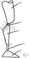
- FIG. 1shows a schematic illustration of a leg prosthesis
- FIG. 2shows an illustration of a control diagram.
- FIG. 1shows, in a schematic illustration, a leg prosthesis with an upper part 1 to which a thigh socket 10 for receiving a thigh stump is fastened.
- a lower part 2 designed as a lower leg partis arranged pivotably on the upper part 1 .
- the lower part 2is mounted on the upper part 1 pivotably about a pivot axis 4 .
- the lower part 2has a lower leg tube 5 , to the distal end of which there is fastened a prosthetic foot 3 in which there may be accommodated a device for determining the axial force acting on the lower leg tube 5 and the ankle moment acting about the fastening point of the prosthetic foot 3 to the lower leg tube 5 .
- a resistance device 6which may be formed for example as a damper or actuator and which is supported between the upper part 1 and the lower part 2 in order to provide an adjustable extension resistance and flexion resistance.
- the resistance device 6is assigned an adjustment device 7 , for example a motor, a magnet or some other actuator, by means of which the respective resistance R within the resistance device 6 can be varied. If the resistance device 6 is formed as a hydraulic damper or pneumatic damper, it is possible by means of the adjustment device 7 for the respective flow cross section of a flow transfer channel to be increased or decreased in size. It is likewise possible for the flow resistance to be varied in some other way by means of the adjustment device 7 .
- resistance deviceis formed as an electric motor operating as a generator, it is possible for an increase or decrease in the respective resistances to flexion or extension to be set through variation of the electrical resistance.
- a control device 8is assigned to the lower part 2 , in particular is accommodated in a lower leg trim, by means of which control device a corresponding activation or deactivation signal is output to the adjustment device 7 .
- the adjustment device 7is activated or deactivated on the basis of sensor data, and the sensor data are provided by one or more sensors 9 which are arranged on the artificial knee joint. These may be angle sensors, acceleration sensors and/or force sensors.
- the sensors 9are connected to the control device 8 , for example by cable or by means of a wireless transmission device. In the exemplary embodiment illustrated, the sensor 9 is formed inter alia as a knee angle sensor.
- the knee angle ⁇ and the flexion damping F Dare plotted versus the time in a diagram.
- the knee angle ⁇is depicted for two walking situations from the start of the stance phase, that is to say from the heel strike HS, up until the terminal stance phase.
- the lower curve profile ⁇ Pshows the knee angle profile for walking on a level surface
- the upper curve profile ⁇ Sshows the knee angle profile for walking down a ramp or stairs, wherein the illustration here relates to the aided leg in the case of alternating walking.
- the normal knee angle profile for walking on a level surface as per curve ⁇ Pbegins at a fully extended position in the region of the heel strike HS, leads, after the initial ground contact, to an increase of the knee angle ⁇ up to a local maximum ⁇ max at the end of the loading response, before then decreasing again during the middle stance phase.
- the legis then in an approximately extended position; during the further course of the step, the knee angle ⁇ increases again in the region of the terminal stance phase and pre-swing phase.
- the knee angle profile for alternating walking down rampshas no decrease at the end of the loading response, with the artificial knee joint rather remaining at a constant value ⁇ max until it is then flexed further earlier than in the case of walking on a level surface.
- the damping resistance F D or flexion resistanceis initially set to an initial damping level F DI which permits flexion of the artificial knee joint upon the initial ground contact but dampens and brakes the flexion in order to prevent a collapse of the artificial knee joint.
- Said initial flexion damping F DIis initially maintained at a constant level until the knee angle ⁇ has reached a threshold value.
- the threshold valueamounts to approximately 30% of the set maximum knee angle ⁇ max that is admissible or considered to be admissible; the increase of the flexion damping F D begins almost directly after the heel strike.
- the threshold valuemay also lie at a greater knee angle, for example at 50% or 70% of the set maximum knee angle ⁇ max that is admissible or considered to be admissible.
- the flexion damping F Dis increased in order to brake the further flexion of the knee joint and block said flexion when the maximum knee angle ⁇ max is reached.
- the flexion dampingis increased progressively, though it may also be increased degressively or linearly.
- the maximum knee angle ⁇ maxis reached, the flexion damping F D is at the maximum flexion damping value F Dmax , at which further flexion is no longer possible.
- Said resistance value F Dmaxis held over a set time period ⁇ T; a plateau D P of the maximum flexion resistance F Dmax forms, and no flexion of the artificial knee joint is possible during said time.
- the time period ⁇ T for which said level F Dmax is heldis detected either by means of a timing switching element or by means of the detection of a forward rotation ⁇ of the lower part 2 , for example of the lower leg tube 5 , or a pivoting movement about the ankle joint of the prosthetic foot 3 .
- a further forward rotation by the angle ⁇which can be detected by means of acceleration sensors, angle sensors and/or inertial angle sensors, the user of the artificial knee joint moves further forward.
- a possible angle range for a further forward rotation ⁇can be assumed to be pivot angles of 5° to 10°.
- the decreaseis degressive, such that initially a rapid decrease of the flexion damping is effected, for example in order to permit a further flexion when walking down a ramp, as shown by the profile of the curve ⁇ S .
- Other profiles of the decrease in dampingmay be set, for example progressively or linearly.
- the plateau region with the resistance plateau D P during the time ⁇ Tno further flexion movement of the artificial knee joint occurs. Only after the flexion resistance F D decreases to a level below the maximum flexion resistance F Dmax , in the illustrated exemplary embodiment above a level of the initial flexion damping F DI in the region of the decrease curve F DS , is an increasing flexion made possible.
- the advantage of such controllies in the high level of safety, which is based on an initial knee flexion always limited to the maximum knee angle ⁇ max , without the extent of movement or the functionality during the further movement sequence being restricted here. If the maximum knee angle ⁇ max is reached and the leg rotates further forward without knee extension occurring, as shown in the curve ⁇ S , the flexion damping F D is reduced in continuous fashion to a high level of damping, possibly to the initial flexion damping F DI . Thus, when walking down ramps or stairs, it is ensured, without any loss of safety, that an undisrupted further movement sequence is possible.
Landscapes
- Health & Medical Sciences (AREA)
- Transplantation (AREA)
- Veterinary Medicine (AREA)
- Life Sciences & Earth Sciences (AREA)
- Public Health (AREA)
- General Health & Medical Sciences (AREA)
- Animal Behavior & Ethology (AREA)
- Vascular Medicine (AREA)
- Oral & Maxillofacial Surgery (AREA)
- Heart & Thoracic Surgery (AREA)
- Biomedical Technology (AREA)
- Engineering & Computer Science (AREA)
- Cardiology (AREA)
- Orthopedic Medicine & Surgery (AREA)
- Epidemiology (AREA)
- Pain & Pain Management (AREA)
- Physical Education & Sports Medicine (AREA)
- Rehabilitation Therapy (AREA)
- Prostheses (AREA)
Abstract
Description
Claims (20)
Applications Claiming Priority (3)
| Application Number | Priority Date | Filing Date | Title |
|---|---|---|---|
| DE102015106392.1ADE102015106392B4 (en) | 2015-04-24 | 2015-04-24 | Method for controlling the stance phase damping of an artificial knee joint |
| DE102015106392.1 | 2015-04-24 | ||
| PCT/EP2016/058394WO2016169853A1 (en) | 2015-04-24 | 2016-04-15 | Method for controlling the standing-phase damping of an artificial knee joint |
Related Parent Applications (1)
| Application Number | Title | Priority Date | Filing Date |
|---|---|---|---|
| PCT/EP2016/058394A-371-Of-InternationalWO2016169853A1 (en) | 2015-04-24 | 2016-04-15 | Method for controlling the standing-phase damping of an artificial knee joint |
Related Child Applications (1)
| Application Number | Title | Priority Date | Filing Date |
|---|---|---|---|
| US17/347,202ContinuationUS11963888B2 (en) | 2015-04-24 | 2021-06-14 | Method for controlling the standing-phase damping of an artificial knee joint |
Publications (2)
| Publication Number | Publication Date |
|---|---|
| US20180085235A1 US20180085235A1 (en) | 2018-03-29 |
| US11033406B2true US11033406B2 (en) | 2021-06-15 |
Family
ID=55754300
Family Applications (2)
| Application Number | Title | Priority Date | Filing Date |
|---|---|---|---|
| US15/568,779Active2036-07-15US11033406B2 (en) | 2015-04-24 | 2016-04-15 | Method for controlling the standing-phase damping of an artificial knee joint |
| US17/347,202Active2036-08-22US11963888B2 (en) | 2015-04-24 | 2021-06-14 | Method for controlling the standing-phase damping of an artificial knee joint |
Family Applications After (1)
| Application Number | Title | Priority Date | Filing Date |
|---|---|---|---|
| US17/347,202Active2036-08-22US11963888B2 (en) | 2015-04-24 | 2021-06-14 | Method for controlling the standing-phase damping of an artificial knee joint |
Country Status (8)
| Country | Link |
|---|---|
| US (2) | US11033406B2 (en) |
| EP (1) | EP3285697B1 (en) |
| JP (1) | JP6751105B2 (en) |
| CN (1) | CN107530174B (en) |
| CA (1) | CA2983649C (en) |
| DE (1) | DE102015106392B4 (en) |
| RU (1) | RU2715683C2 (en) |
| WO (1) | WO2016169853A1 (en) |
Families Citing this family (11)
| Publication number | Priority date | Publication date | Assignee | Title |
|---|---|---|---|---|
| US12059383B2 (en) | 2016-05-03 | 2024-08-13 | Icarus Medical, LLC | Assistive orthotic device with motors and sensors |
| DE102019115098A1 (en)* | 2019-06-05 | 2020-12-10 | Otto Bock Healthcare Products Gmbh | Method for controlling an artificial knee joint |
| DE102019128508B4 (en)* | 2019-10-22 | 2021-07-22 | Otto Bock Healthcare Products Gmbh | Orthopedic joint and method for its control |
| CN110916974B (en)* | 2019-12-02 | 2021-07-13 | 郑州大学第一附属医院 | Ankle protection and rehabilitation training device |
| DE102020004339B4 (en)* | 2020-07-20 | 2022-03-03 | Otto Bock Healthcare Products Gmbh | Method for controlling a prosthesis or orthosis |
| DE102020004336A1 (en)* | 2020-07-20 | 2022-01-20 | Otto Bock Healthcare Products Gmbh | Method for controlling a prosthesis or orthosis |
| JP2023003724A (en)* | 2021-06-24 | 2023-01-17 | トヨタ自動車株式会社 | Knee movement support device |
| JP7548150B2 (en)* | 2021-07-26 | 2024-09-10 | トヨタ自動車株式会社 | Walking assistance device, control method, and control program |
| CN117357313B (en)* | 2023-12-08 | 2024-04-09 | 浙江强脑科技有限公司 | Resistance control method and device based on intention switching, artificial limb, terminal and medium |
| WO2025171100A1 (en)* | 2024-02-09 | 2025-08-14 | College Park Industries, Inc. | System and method for resistance control of a microprocessor-controlled prosthetic knee |
| CN118615076B (en)* | 2024-08-15 | 2025-02-11 | 浙江强脑科技有限公司 | Control method, device and storage medium for artificial leg climbing stairs |
Citations (23)
| Publication number | Priority date | Publication date | Assignee | Title |
|---|---|---|---|---|
| CN1074109A (en) | 1991-12-05 | 1993-07-14 | 奥托伯克矫形外科工业产业管理两合公司 | The system of control artificial knee joint action in above-knee prosthesis |
| CN1431888A (en) | 2000-03-29 | 2003-07-23 | 麻省理工学院 | Accommodates speed and adapts to the patient's prosthetic knee |
| US20050015156A1 (en) | 2003-07-17 | 2005-01-20 | Yuichi Hikichi | Above-knee prosthesis with variable resistance knee joint |
| RU2254832C1 (en) | 2003-11-26 | 2005-06-27 | Общество с ограниченной ответственностью "МЕТИЗ" | Artificial knee joint having means for controlling braking forces independently under flexion and extension conditions |
| DE102006021802A1 (en) | 2006-05-09 | 2007-11-15 | Otto Bock Healthcare Ip Gmbh & Co. Kg | Control of a passive prosthetic knee joint with adjustable damping |
| US20090054996A1 (en) | 2006-03-24 | 2009-02-26 | Andrew John Sykes | Lower Limb Prosthesis and Control Unit |
| DE102007053389A1 (en) | 2007-11-07 | 2009-05-20 | Otto Bock Healthcare Ip Gmbh & Co. | Method for controlling an orthopedic joint |
| US20090192619A1 (en)* | 2007-11-23 | 2009-07-30 | Orthocare Innovations Llc | Passive electro-magnetically damped joint |
| DE102008008284A1 (en) | 2008-02-07 | 2009-08-13 | Otto Bock Healthcare Gmbh | Orthopedic knee joint and method for controlling an orthopedic knee joint |
| US20090265018A1 (en)* | 2008-04-21 | 2009-10-22 | Vanderbilt University | Powered leg prosthesis and control methodologies for obtaining near normal gait |
| US20100023133A1 (en)* | 2008-06-16 | 2010-01-28 | Berkeley Bionics | Semi-actuated transfemoral prosthetic knee |
| US20100049334A1 (en) | 2007-03-16 | 2010-02-25 | Masahiko Okuda | Prosthetic limbs with means capable of reducing torque in the initial period of bend of knee joint |
| CN101961271A (en) | 2010-09-13 | 2011-02-02 | 北京大学 | Dynamic knee prothesis-based impedance control method |
| DE102009052890A1 (en) | 2009-11-13 | 2011-05-19 | Otto Bock Healthcare Products Gmbh | Device and method for controlling an artificial orthotic or prosthetic joint |
| DE102009052895A1 (en) | 2009-11-13 | 2011-05-19 | Otto Bock Healthcare Products Gmbh | Method and device for controlling an artificial orthotic or prosthetic knee joint |
| DE102009052887A1 (en) | 2009-11-13 | 2011-05-19 | Otto Bock Healthcare Products Gmbh | Method for controlling an orthotic or prosthetic joint of a lower extremity |
| US20120226365A1 (en)* | 2009-11-13 | 2012-09-06 | Otto Bock Healthcare Products Gmbh | Method and device for controlling an artificial orthotic or prosthetic joint |
| DE102012003369A1 (en) | 2012-02-22 | 2013-08-22 | Otto Bock Healthcare Gmbh | Method for controlling an artificial orthotic or prosthetic knee joint |
| CN103271783A (en) | 2013-05-16 | 2013-09-04 | 清华大学 | Artificial limb knee joint with assistance function |
| US20130310949A1 (en)* | 2012-05-15 | 2013-11-21 | Vanderbilt University | Stair ascent and descent control for powered lower limb devices |
| DE102012013141A1 (en) | 2012-07-03 | 2014-05-08 | Otto Bock Healthcare Gmbh | Orthotic or prosthetic joint device and method for its control |
| US20140379096A1 (en)* | 2011-12-13 | 2014-12-25 | Blatchford Products Limited | Lower limb prosthesis |
| US20160206447A1 (en)* | 2013-08-22 | 2016-07-21 | Otto Bock Healthcare Products Gmbh | Method for controlling an artificial orthotic or prosthetic kneejoint |
- 2015
- 2015-04-24DEDE102015106392.1Apatent/DE102015106392B4/ennot_activeExpired - Fee Related
- 2016
- 2016-04-15EPEP16716594.3Apatent/EP3285697B1/enactiveActive
- 2016-04-15RURU2017140337Apatent/RU2715683C2/enactive
- 2016-04-15JPJP2017555539Apatent/JP6751105B2/enactiveActive
- 2016-04-15WOPCT/EP2016/058394patent/WO2016169853A1/ennot_activeCeased
- 2016-04-15CNCN201680023618.7Apatent/CN107530174B/enactiveActive
- 2016-04-15USUS15/568,779patent/US11033406B2/enactiveActive
- 2016-04-15CACA2983649Apatent/CA2983649C/enactiveActive
- 2021
- 2021-06-14USUS17/347,202patent/US11963888B2/enactiveActive
Patent Citations (42)
| Publication number | Priority date | Publication date | Assignee | Title |
|---|---|---|---|---|
| US5571205A (en) | 1991-12-05 | 1996-11-05 | James; Kelvin B. | System for controlling artificial knee joint action in an above knee prosthesis |
| CN1074109A (en) | 1991-12-05 | 1993-07-14 | 奥托伯克矫形外科工业产业管理两合公司 | The system of control artificial knee joint action in above-knee prosthesis |
| US7799091B2 (en)* | 2000-03-29 | 2010-09-21 | Massachusetts Institute Of Technology | Control system for prosthetic knee |
| CN1431888A (en) | 2000-03-29 | 2003-07-23 | 麻省理工学院 | Accommodates speed and adapts to the patient's prosthetic knee |
| US6610101B2 (en) | 2000-03-29 | 2003-08-26 | Massachusetts Institute Of Technology | Speed-adaptive and patient-adaptive prosthetic knee |
| US20050015156A1 (en) | 2003-07-17 | 2005-01-20 | Yuichi Hikichi | Above-knee prosthesis with variable resistance knee joint |
| RU2254832C1 (en) | 2003-11-26 | 2005-06-27 | Общество с ограниченной ответственностью "МЕТИЗ" | Artificial knee joint having means for controlling braking forces independently under flexion and extension conditions |
| US20090054996A1 (en) | 2006-03-24 | 2009-02-26 | Andrew John Sykes | Lower Limb Prosthesis and Control Unit |
| DE102006021802A1 (en) | 2006-05-09 | 2007-11-15 | Otto Bock Healthcare Ip Gmbh & Co. Kg | Control of a passive prosthetic knee joint with adjustable damping |
| US20090171468A1 (en) | 2006-05-09 | 2009-07-02 | Otto Bock Healthcare Ip | Control of a passive prosthetic knee joint with adjustable damping |
| CN101453963A (en) | 2006-05-09 | 2009-06-10 | 奥托·博克保健Ip两合公司 | Control of a passive prosthetic knee joint with adjustable damping |
| JP2009536050A (en) | 2006-05-09 | 2009-10-08 | オットー・ボック・ヘルスケア・アイピー・ゲーエムベーハー・ウント・コンパニー・カーゲー | How to control a passive knee prosthesis with adjustable braking function |
| US10265198B2 (en) | 2006-05-09 | 2019-04-23 | Otto Bock Healthcare Gmbh | Control of a passive prosthetic knee joint with adjustable damping |
| US7731759B2 (en) | 2006-05-09 | 2010-06-08 | Otto Bock Healthcare Gmbh | Control of a passive prosthetic knee joint with adjustable damping |
| US20100049334A1 (en) | 2007-03-16 | 2010-02-25 | Masahiko Okuda | Prosthetic limbs with means capable of reducing torque in the initial period of bend of knee joint |
| DE102007053389A1 (en) | 2007-11-07 | 2009-05-20 | Otto Bock Healthcare Ip Gmbh & Co. | Method for controlling an orthopedic joint |
| US20100305716A1 (en) | 2007-11-07 | 2010-12-02 | Otto Bock Healthcare Gmbh | Method for controlling an orthopedic joint |
| US20090192619A1 (en)* | 2007-11-23 | 2009-07-30 | Orthocare Innovations Llc | Passive electro-magnetically damped joint |
| DE102008008284A1 (en) | 2008-02-07 | 2009-08-13 | Otto Bock Healthcare Gmbh | Orthopedic knee joint and method for controlling an orthopedic knee joint |
| US20110087339A1 (en) | 2008-02-07 | 2011-04-14 | Otto Bock Healthcare Gmbh | Orthopedic knee joint and method for controlling an orthopedic knee joint |
| US20090265018A1 (en)* | 2008-04-21 | 2009-10-22 | Vanderbilt University | Powered leg prosthesis and control methodologies for obtaining near normal gait |
| US20100023133A1 (en)* | 2008-06-16 | 2010-01-28 | Berkeley Bionics | Semi-actuated transfemoral prosthetic knee |
| CN102065799A (en) | 2008-06-16 | 2011-05-18 | 伯克利仿生技术公司 | Semi-actuated transfemoral prosthetic knee |
| US8231688B2 (en) | 2008-06-16 | 2012-07-31 | Berkeley Bionics | Semi-actuated transfemoral prosthetic knee |
| US20120232674A1 (en) | 2009-11-13 | 2012-09-13 | Otto Bock Healthcare Products Gmbh | Method and device for controlling an artificial orthotic or prosthetic knee joint |
| DE102009052895A1 (en) | 2009-11-13 | 2011-05-19 | Otto Bock Healthcare Products Gmbh | Method and device for controlling an artificial orthotic or prosthetic knee joint |
| US20120215323A1 (en) | 2009-11-13 | 2012-08-23 | Otto Bock Healthcare Products Gmbh | Device and method for controlling an artificial orthotic or prosthetic joint |
| US20120226365A1 (en)* | 2009-11-13 | 2012-09-06 | Otto Bock Healthcare Products Gmbh | Method and device for controlling an artificial orthotic or prosthetic joint |
| US20120226364A1 (en) | 2009-11-13 | 2012-09-06 | Otto Bock Healthcare Products Gmbh | Method for controlling an orthotic or prosthetic joint of a lower extremity |
| DE102009052890A1 (en) | 2009-11-13 | 2011-05-19 | Otto Bock Healthcare Products Gmbh | Device and method for controlling an artificial orthotic or prosthetic joint |
| CN102740803A (en) | 2009-11-13 | 2012-10-17 | 奥托·博克保健产品有限公司 | Method of controlling orthotic or prosthetic joints of lower extremities |
| CA2779784C (en) | 2009-11-13 | 2017-07-11 | Otto Bock Healthcare Products Gmbh | Method for controlling an orthotic or prosthetic joint of a lower extremity |
| DE102009052887A1 (en) | 2009-11-13 | 2011-05-19 | Otto Bock Healthcare Products Gmbh | Method for controlling an orthotic or prosthetic joint of a lower extremity |
| CN101961271A (en) | 2010-09-13 | 2011-02-02 | 北京大学 | Dynamic knee prothesis-based impedance control method |
| US20140379096A1 (en)* | 2011-12-13 | 2014-12-25 | Blatchford Products Limited | Lower limb prosthesis |
| US20150018972A1 (en) | 2012-02-22 | 2015-01-15 | Otto Bock Healthcare Gmbh | Method for controlling an artificial orthotic or prosthetic knee joint |
| DE102012003369A1 (en) | 2012-02-22 | 2013-08-22 | Otto Bock Healthcare Gmbh | Method for controlling an artificial orthotic or prosthetic knee joint |
| US20130310949A1 (en)* | 2012-05-15 | 2013-11-21 | Vanderbilt University | Stair ascent and descent control for powered lower limb devices |
| DE102012013141A1 (en) | 2012-07-03 | 2014-05-08 | Otto Bock Healthcare Gmbh | Orthotic or prosthetic joint device and method for its control |
| US20150164660A1 (en) | 2012-07-03 | 2015-06-18 | Otto Bock Healthcare Gmbh | Orthotic or prosthetic joint device, and method for controlling same |
| CN103271783A (en) | 2013-05-16 | 2013-09-04 | 清华大学 | Artificial limb knee joint with assistance function |
| US20160206447A1 (en)* | 2013-08-22 | 2016-07-21 | Otto Bock Healthcare Products Gmbh | Method for controlling an artificial orthotic or prosthetic kneejoint |
Non-Patent Citations (1)
| Title |
|---|
| PCT International Search Report for PCT International Patent Application No. PCT/EP2016/058394, dated Jun. 16, 2016. |
Also Published As
| Publication number | Publication date |
|---|---|
| JP2018516635A (en) | 2018-06-28 |
| US20210298921A1 (en) | 2021-09-30 |
| CN107530174A (en) | 2018-01-02 |
| JP6751105B2 (en) | 2020-09-02 |
| RU2017140337A3 (en) | 2019-09-05 |
| RU2715683C2 (en) | 2020-03-02 |
| EP3285697B1 (en) | 2019-07-17 |
| CN107530174B (en) | 2020-09-22 |
| US11963888B2 (en) | 2024-04-23 |
| DE102015106392A1 (en) | 2016-10-27 |
| DE102015106392B4 (en) | 2020-07-09 |
| CA2983649A1 (en) | 2016-10-27 |
| CA2983649C (en) | 2023-09-26 |
| RU2017140337A (en) | 2019-05-24 |
| WO2016169853A1 (en) | 2016-10-27 |
| EP3285697A1 (en) | 2018-02-28 |
| US20180085235A1 (en) | 2018-03-29 |
Similar Documents
| Publication | Publication Date | Title |
|---|---|---|
| US11963888B2 (en) | Method for controlling the standing-phase damping of an artificial knee joint | |
| US20200397599A1 (en) | Method for controlling a change of damping in an artificial joint | |
| US20220202593A1 (en) | Method for controlling a damping modification | |
| US9572690B2 (en) | Method and device for controlling an artificial orthotic or prosthetic joint | |
| US10398575B2 (en) | Method and device for controlling an artificial orthotic or prosthetic knee joint | |
| US20220346982A1 (en) | Method for controlling an artificial knee joint | |
| CN102724936B (en) | Device and method for controlling an artificial orthotic or prosthetic joint | |
| CN101909553A (en) | Method for controlling an orthopedic joint | |
| CA2779784A1 (en) | Method for controlling an orthotic or prosthetic joint of a lower extremity | |
| US20230270570A1 (en) | Method for controlling a prosthesis or orthesis | |
| CN113329720B (en) | Method for controlling an orthopaedic or prosthetic device and orthopaedic or prosthetic device | |
| US10517744B2 (en) | Method for controlling an artificial knee joint | |
| CN102711672B (en) | Method and device for controlling artificial orthopedic or prosthetic joints | |
| US20230293320A1 (en) | Method for controlling a prosthesis or orthosis | |
| CN120569176A (en) | Orthopedic technology device and control method thereof |
Legal Events
| Date | Code | Title | Description |
|---|---|---|---|
| FEPP | Fee payment procedure | Free format text:ENTITY STATUS SET TO UNDISCOUNTED (ORIGINAL EVENT CODE: BIG.); ENTITY STATUS OF PATENT OWNER: LARGE ENTITY | |
| AS | Assignment | Owner name:OTTO BOCK HEALTHCARE PRODUCTS GMBH, AUSTRIA Free format text:ASSIGNMENT OF ASSIGNORS INTEREST;ASSIGNORS:SEIFERT, DIRK;ZARLING, SVEN;SIGNING DATES FROM 20171109 TO 20171110;REEL/FRAME:044790/0043 | |
| STPP | Information on status: patent application and granting procedure in general | Free format text:NON FINAL ACTION MAILED | |
| STPP | Information on status: patent application and granting procedure in general | Free format text:RESPONSE TO NON-FINAL OFFICE ACTION ENTERED AND FORWARDED TO EXAMINER | |
| STPP | Information on status: patent application and granting procedure in general | Free format text:FINAL REJECTION MAILED | |
| STPP | Information on status: patent application and granting procedure in general | Free format text:DOCKETED NEW CASE - READY FOR EXAMINATION | |
| STPP | Information on status: patent application and granting procedure in general | Free format text:NON FINAL ACTION MAILED | |
| STPP | Information on status: patent application and granting procedure in general | Free format text:RESPONSE TO NON-FINAL OFFICE ACTION ENTERED AND FORWARDED TO EXAMINER | |
| STPP | Information on status: patent application and granting procedure in general | Free format text:NOTICE OF ALLOWANCE MAILED -- APPLICATION RECEIVED IN OFFICE OF PUBLICATIONS | |
| STPP | Information on status: patent application and granting procedure in general | Free format text:PUBLICATIONS -- ISSUE FEE PAYMENT RECEIVED | |
| STPP | Information on status: patent application and granting procedure in general | Free format text:PUBLICATIONS -- ISSUE FEE PAYMENT VERIFIED | |
| STCF | Information on status: patent grant | Free format text:PATENTED CASE | |
| MAFP | Maintenance fee payment | Free format text:PAYMENT OF MAINTENANCE FEE, 4TH YEAR, LARGE ENTITY (ORIGINAL EVENT CODE: M1551); ENTITY STATUS OF PATENT OWNER: LARGE ENTITY Year of fee payment:4 |