US11033402B2 - Expandable interbody implant - Google Patents
Expandable interbody implantDownload PDFInfo
- Publication number
- US11033402B2 US11033402B2US15/926,493US201815926493AUS11033402B2US 11033402 B2US11033402 B2US 11033402B2US 201815926493 AUS201815926493 AUS 201815926493AUS 11033402 B2US11033402 B2US 11033402B2
- Authority
- US
- United States
- Prior art keywords
- bone graft
- implant
- storage portion
- drive link
- graft storage
- Prior art date
- Legal status (The legal status is an assumption and is not a legal conclusion. Google has not performed a legal analysis and makes no representation as to the accuracy of the status listed.)
- Active, expires
Links
- 239000007943implantSubstances0.000titleclaimsabstractdescription90
- 210000000988bone and boneAnatomy0.000claimsabstractdescription68
- 230000033001locomotionEffects0.000claimsabstractdescription28
- 239000000463materialSubstances0.000claimsabstractdescription25
- 230000008468bone growthEffects0.000claimsabstractdescription16
- 238000003780insertionMethods0.000claimsabstractdescription13
- 230000037431insertionEffects0.000claimsabstractdescription13
- 238000000034methodMethods0.000claims23
- 230000014759maintenance of locationEffects0.000abstract1
- 230000015572biosynthetic processEffects0.000description3
- 230000001045lordotic effectEffects0.000description3
- 210000004705lumbosacral regionAnatomy0.000description2
- 208000007623LordosisDiseases0.000description1
- 230000007423decreaseEffects0.000description1
- 230000004927fusionEffects0.000description1
- 230000007246mechanismEffects0.000description1
- 238000012986modificationMethods0.000description1
- 230000004048modificationEffects0.000description1
Images


Classifications
- A—HUMAN NECESSITIES
- A61—MEDICAL OR VETERINARY SCIENCE; HYGIENE
- A61F—FILTERS IMPLANTABLE INTO BLOOD VESSELS; PROSTHESES; DEVICES PROVIDING PATENCY TO, OR PREVENTING COLLAPSING OF, TUBULAR STRUCTURES OF THE BODY, e.g. STENTS; ORTHOPAEDIC, NURSING OR CONTRACEPTIVE DEVICES; FOMENTATION; TREATMENT OR PROTECTION OF EYES OR EARS; BANDAGES, DRESSINGS OR ABSORBENT PADS; FIRST-AID KITS
- A61F2/00—Filters implantable into blood vessels; Prostheses, i.e. artificial substitutes or replacements for parts of the body; Appliances for connecting them with the body; Devices providing patency to, or preventing collapsing of, tubular structures of the body, e.g. stents
- A61F2/02—Prostheses implantable into the body
- A61F2/30—Joints
- A61F2/44—Joints for the spine, e.g. vertebrae, spinal discs
- A61F2/4455—Joints for the spine, e.g. vertebrae, spinal discs for the fusion of spinal bodies, e.g. intervertebral fusion of adjacent spinal bodies, e.g. fusion cages
- A—HUMAN NECESSITIES
- A61—MEDICAL OR VETERINARY SCIENCE; HYGIENE
- A61B—DIAGNOSIS; SURGERY; IDENTIFICATION
- A61B17/00—Surgical instruments, devices or methods
- A61B17/56—Surgical instruments or methods for treatment of bones or joints; Devices specially adapted therefor
- A61B17/58—Surgical instruments or methods for treatment of bones or joints; Devices specially adapted therefor for osteosynthesis, e.g. bone plates, screws or setting implements
- A61B17/68—Internal fixation devices, including fasteners and spinal fixators, even if a part thereof projects from the skin
- A61B17/70—Spinal positioners or stabilisers, e.g. stabilisers comprising fluid filler in an implant
- A61B17/7071—Implants for expanding or repairing the vertebral arch or wedged between laminae or pedicles; Tools therefor
- A—HUMAN NECESSITIES
- A61—MEDICAL OR VETERINARY SCIENCE; HYGIENE
- A61B—DIAGNOSIS; SURGERY; IDENTIFICATION
- A61B17/00—Surgical instruments, devices or methods
- A61B17/56—Surgical instruments or methods for treatment of bones or joints; Devices specially adapted therefor
- A61B17/58—Surgical instruments or methods for treatment of bones or joints; Devices specially adapted therefor for osteosynthesis, e.g. bone plates, screws or setting implements
- A61B17/68—Internal fixation devices, including fasteners and spinal fixators, even if a part thereof projects from the skin
- A61B17/70—Spinal positioners or stabilisers, e.g. stabilisers comprising fluid filler in an implant
- A61B17/7097—Stabilisers comprising fluid filler in an implant, e.g. balloon; devices for inserting or filling such implants
- A—HUMAN NECESSITIES
- A61—MEDICAL OR VETERINARY SCIENCE; HYGIENE
- A61F—FILTERS IMPLANTABLE INTO BLOOD VESSELS; PROSTHESES; DEVICES PROVIDING PATENCY TO, OR PREVENTING COLLAPSING OF, TUBULAR STRUCTURES OF THE BODY, e.g. STENTS; ORTHOPAEDIC, NURSING OR CONTRACEPTIVE DEVICES; FOMENTATION; TREATMENT OR PROTECTION OF EYES OR EARS; BANDAGES, DRESSINGS OR ABSORBENT PADS; FIRST-AID KITS
- A61F2/00—Filters implantable into blood vessels; Prostheses, i.e. artificial substitutes or replacements for parts of the body; Appliances for connecting them with the body; Devices providing patency to, or preventing collapsing of, tubular structures of the body, e.g. stents
- A61F2/02—Prostheses implantable into the body
- A61F2/30—Joints
- A61F2/44—Joints for the spine, e.g. vertebrae, spinal discs
- A61F2/4455—Joints for the spine, e.g. vertebrae, spinal discs for the fusion of spinal bodies, e.g. intervertebral fusion of adjacent spinal bodies, e.g. fusion cages
- A61F2/447—Joints for the spine, e.g. vertebrae, spinal discs for the fusion of spinal bodies, e.g. intervertebral fusion of adjacent spinal bodies, e.g. fusion cages substantially parallelepipedal, e.g. having a rectangular or trapezoidal cross-section
- A—HUMAN NECESSITIES
- A61—MEDICAL OR VETERINARY SCIENCE; HYGIENE
- A61F—FILTERS IMPLANTABLE INTO BLOOD VESSELS; PROSTHESES; DEVICES PROVIDING PATENCY TO, OR PREVENTING COLLAPSING OF, TUBULAR STRUCTURES OF THE BODY, e.g. STENTS; ORTHOPAEDIC, NURSING OR CONTRACEPTIVE DEVICES; FOMENTATION; TREATMENT OR PROTECTION OF EYES OR EARS; BANDAGES, DRESSINGS OR ABSORBENT PADS; FIRST-AID KITS
- A61F2/00—Filters implantable into blood vessels; Prostheses, i.e. artificial substitutes or replacements for parts of the body; Appliances for connecting them with the body; Devices providing patency to, or preventing collapsing of, tubular structures of the body, e.g. stents
- A61F2/02—Prostheses implantable into the body
- A61F2/30—Joints
- A61F2/46—Special tools for implanting artificial joints
- A61F2/4603—Special tools for implanting artificial joints for insertion or extraction of endoprosthetic joints or of accessories thereof
- A61F2/4611—Special tools for implanting artificial joints for insertion or extraction of endoprosthetic joints or of accessories thereof of spinal prostheses
- A—HUMAN NECESSITIES
- A61—MEDICAL OR VETERINARY SCIENCE; HYGIENE
- A61F—FILTERS IMPLANTABLE INTO BLOOD VESSELS; PROSTHESES; DEVICES PROVIDING PATENCY TO, OR PREVENTING COLLAPSING OF, TUBULAR STRUCTURES OF THE BODY, e.g. STENTS; ORTHOPAEDIC, NURSING OR CONTRACEPTIVE DEVICES; FOMENTATION; TREATMENT OR PROTECTION OF EYES OR EARS; BANDAGES, DRESSINGS OR ABSORBENT PADS; FIRST-AID KITS
- A61F2/00—Filters implantable into blood vessels; Prostheses, i.e. artificial substitutes or replacements for parts of the body; Appliances for connecting them with the body; Devices providing patency to, or preventing collapsing of, tubular structures of the body, e.g. stents
- A61F2/02—Prostheses implantable into the body
- A61F2/30—Joints
- A61F2002/30001—Additional features of subject-matter classified in A61F2/28, A61F2/30 and subgroups thereof
- A61F2002/30316—The prosthesis having different structural features at different locations within the same prosthesis; Connections between prosthetic parts; Special structural features of bone or joint prostheses not otherwise provided for
- A61F2002/30329—Connections or couplings between prosthetic parts, e.g. between modular parts; Connecting elements
- A61F2002/30428—Connections or couplings between prosthetic parts, e.g. between modular parts; Connecting elements made by inserting a protrusion into a slot
- A—HUMAN NECESSITIES
- A61—MEDICAL OR VETERINARY SCIENCE; HYGIENE
- A61F—FILTERS IMPLANTABLE INTO BLOOD VESSELS; PROSTHESES; DEVICES PROVIDING PATENCY TO, OR PREVENTING COLLAPSING OF, TUBULAR STRUCTURES OF THE BODY, e.g. STENTS; ORTHOPAEDIC, NURSING OR CONTRACEPTIVE DEVICES; FOMENTATION; TREATMENT OR PROTECTION OF EYES OR EARS; BANDAGES, DRESSINGS OR ABSORBENT PADS; FIRST-AID KITS
- A61F2/00—Filters implantable into blood vessels; Prostheses, i.e. artificial substitutes or replacements for parts of the body; Appliances for connecting them with the body; Devices providing patency to, or preventing collapsing of, tubular structures of the body, e.g. stents
- A61F2/02—Prostheses implantable into the body
- A61F2/30—Joints
- A61F2002/30001—Additional features of subject-matter classified in A61F2/28, A61F2/30 and subgroups thereof
- A61F2002/30316—The prosthesis having different structural features at different locations within the same prosthesis; Connections between prosthetic parts; Special structural features of bone or joint prostheses not otherwise provided for
- A61F2002/30329—Connections or couplings between prosthetic parts, e.g. between modular parts; Connecting elements
- A61F2002/30471—Connections or couplings between prosthetic parts, e.g. between modular parts; Connecting elements connected by a hinged linkage mechanism, e.g. of the single-bar or multi-bar linkage type
- A—HUMAN NECESSITIES
- A61—MEDICAL OR VETERINARY SCIENCE; HYGIENE
- A61F—FILTERS IMPLANTABLE INTO BLOOD VESSELS; PROSTHESES; DEVICES PROVIDING PATENCY TO, OR PREVENTING COLLAPSING OF, TUBULAR STRUCTURES OF THE BODY, e.g. STENTS; ORTHOPAEDIC, NURSING OR CONTRACEPTIVE DEVICES; FOMENTATION; TREATMENT OR PROTECTION OF EYES OR EARS; BANDAGES, DRESSINGS OR ABSORBENT PADS; FIRST-AID KITS
- A61F2/00—Filters implantable into blood vessels; Prostheses, i.e. artificial substitutes or replacements for parts of the body; Appliances for connecting them with the body; Devices providing patency to, or preventing collapsing of, tubular structures of the body, e.g. stents
- A61F2/02—Prostheses implantable into the body
- A61F2/30—Joints
- A61F2002/30001—Additional features of subject-matter classified in A61F2/28, A61F2/30 and subgroups thereof
- A61F2002/30316—The prosthesis having different structural features at different locations within the same prosthesis; Connections between prosthetic parts; Special structural features of bone or joint prostheses not otherwise provided for
- A61F2002/30329—Connections or couplings between prosthetic parts, e.g. between modular parts; Connecting elements
- A61F2002/30476—Connections or couplings between prosthetic parts, e.g. between modular parts; Connecting elements locked by an additional locking mechanism
- A61F2002/30507—Connections or couplings between prosthetic parts, e.g. between modular parts; Connecting elements locked by an additional locking mechanism using a threaded locking member, e.g. a locking screw or a set screw
- A—HUMAN NECESSITIES
- A61—MEDICAL OR VETERINARY SCIENCE; HYGIENE
- A61F—FILTERS IMPLANTABLE INTO BLOOD VESSELS; PROSTHESES; DEVICES PROVIDING PATENCY TO, OR PREVENTING COLLAPSING OF, TUBULAR STRUCTURES OF THE BODY, e.g. STENTS; ORTHOPAEDIC, NURSING OR CONTRACEPTIVE DEVICES; FOMENTATION; TREATMENT OR PROTECTION OF EYES OR EARS; BANDAGES, DRESSINGS OR ABSORBENT PADS; FIRST-AID KITS
- A61F2/00—Filters implantable into blood vessels; Prostheses, i.e. artificial substitutes or replacements for parts of the body; Appliances for connecting them with the body; Devices providing patency to, or preventing collapsing of, tubular structures of the body, e.g. stents
- A61F2/02—Prostheses implantable into the body
- A61F2/30—Joints
- A61F2002/30001—Additional features of subject-matter classified in A61F2/28, A61F2/30 and subgroups thereof
- A61F2002/30316—The prosthesis having different structural features at different locations within the same prosthesis; Connections between prosthetic parts; Special structural features of bone or joint prostheses not otherwise provided for
- A61F2002/30535—Special structural features of bone or joint prostheses not otherwise provided for
- A61F2002/30537—Special structural features of bone or joint prostheses not otherwise provided for adjustable
- A61F2002/30538—Special structural features of bone or joint prostheses not otherwise provided for adjustable for adjusting angular orientation
- A—HUMAN NECESSITIES
- A61—MEDICAL OR VETERINARY SCIENCE; HYGIENE
- A61F—FILTERS IMPLANTABLE INTO BLOOD VESSELS; PROSTHESES; DEVICES PROVIDING PATENCY TO, OR PREVENTING COLLAPSING OF, TUBULAR STRUCTURES OF THE BODY, e.g. STENTS; ORTHOPAEDIC, NURSING OR CONTRACEPTIVE DEVICES; FOMENTATION; TREATMENT OR PROTECTION OF EYES OR EARS; BANDAGES, DRESSINGS OR ABSORBENT PADS; FIRST-AID KITS
- A61F2/00—Filters implantable into blood vessels; Prostheses, i.e. artificial substitutes or replacements for parts of the body; Appliances for connecting them with the body; Devices providing patency to, or preventing collapsing of, tubular structures of the body, e.g. stents
- A61F2/02—Prostheses implantable into the body
- A61F2/30—Joints
- A61F2002/30001—Additional features of subject-matter classified in A61F2/28, A61F2/30 and subgroups thereof
- A61F2002/30316—The prosthesis having different structural features at different locations within the same prosthesis; Connections between prosthetic parts; Special structural features of bone or joint prostheses not otherwise provided for
- A61F2002/30535—Special structural features of bone or joint prostheses not otherwise provided for
- A61F2002/30581—Special structural features of bone or joint prostheses not otherwise provided for having a pocket filled with fluid, e.g. liquid
- A—HUMAN NECESSITIES
- A61—MEDICAL OR VETERINARY SCIENCE; HYGIENE
- A61F—FILTERS IMPLANTABLE INTO BLOOD VESSELS; PROSTHESES; DEVICES PROVIDING PATENCY TO, OR PREVENTING COLLAPSING OF, TUBULAR STRUCTURES OF THE BODY, e.g. STENTS; ORTHOPAEDIC, NURSING OR CONTRACEPTIVE DEVICES; FOMENTATION; TREATMENT OR PROTECTION OF EYES OR EARS; BANDAGES, DRESSINGS OR ABSORBENT PADS; FIRST-AID KITS
- A61F2/00—Filters implantable into blood vessels; Prostheses, i.e. artificial substitutes or replacements for parts of the body; Appliances for connecting them with the body; Devices providing patency to, or preventing collapsing of, tubular structures of the body, e.g. stents
- A61F2/02—Prostheses implantable into the body
- A61F2/30—Joints
- A61F2002/30001—Additional features of subject-matter classified in A61F2/28, A61F2/30 and subgroups thereof
- A61F2002/30316—The prosthesis having different structural features at different locations within the same prosthesis; Connections between prosthetic parts; Special structural features of bone or joint prostheses not otherwise provided for
- A61F2002/30535—Special structural features of bone or joint prostheses not otherwise provided for
- A61F2002/30593—Special structural features of bone or joint prostheses not otherwise provided for hollow
- A—HUMAN NECESSITIES
- A61—MEDICAL OR VETERINARY SCIENCE; HYGIENE
- A61F—FILTERS IMPLANTABLE INTO BLOOD VESSELS; PROSTHESES; DEVICES PROVIDING PATENCY TO, OR PREVENTING COLLAPSING OF, TUBULAR STRUCTURES OF THE BODY, e.g. STENTS; ORTHOPAEDIC, NURSING OR CONTRACEPTIVE DEVICES; FOMENTATION; TREATMENT OR PROTECTION OF EYES OR EARS; BANDAGES, DRESSINGS OR ABSORBENT PADS; FIRST-AID KITS
- A61F2/00—Filters implantable into blood vessels; Prostheses, i.e. artificial substitutes or replacements for parts of the body; Appliances for connecting them with the body; Devices providing patency to, or preventing collapsing of, tubular structures of the body, e.g. stents
- A61F2/02—Prostheses implantable into the body
- A61F2/30—Joints
- A61F2/30767—Special external or bone-contacting surface, e.g. coating for improving bone ingrowth
- A61F2/30771—Special external or bone-contacting surface, e.g. coating for improving bone ingrowth applied in original prostheses, e.g. holes or grooves
- A61F2002/30904—Special external or bone-contacting surface, e.g. coating for improving bone ingrowth applied in original prostheses, e.g. holes or grooves serrated profile, i.e. saw-toothed
Definitions
- the present inventionrelates generally to an expandable interbody implant, and more particularly to a lordotic expandable interbody implant adapted for oblique posterior, oblique anterior, co-axial posterior, or co-axial anterior, insertion and placement in a disc space having a surgically-corrected height between adjacent vertebral bodies in the lumbar spine.
- Lordotic expandable spinal fusion implantsare known in the art.
- the lordotic, tapered configuration of such known implantsassists in the restoration or enhancement of spinal lordosis in the lumbar spine.
- the expandability of such implantsallows placement of a potentially larger implant through a smaller opening in a patient's body, with selective expansion in a selected direction providing the advantage of increasing the height of the implant and corresponding distraction of the disc space, without a concomitant increase in the width of the implant.
- the related art implantshowever, have certain disadvantages.
- the configurations of the leading ends of the related art implantslimit the preferred placement of the implants in the disc space to be along an axis defined between the anterior and posterior portion of the disc space. Oblique placement has not been optimized with the related art implants.
- the related art implantstypically employ ramp-on-ramp linkage mechanisms, which have proven to be unreliable in enabling such implants to smoothly and reliably increase to a selected height desired by the surgeon.
- the related art implantshave experienced difficulty with maintaining, during insertion and expansion within the disc space, a selected volume of bone graft material stored in the implant. During expansion of such related-art implants within the disc space, some of the stored bone graft material often escapes, thereby reducing the selected volume of bone graft material stored in the implant.
- an expandable interbody implantin accordance with the present invention, includes a leading end, and a trailing end, adapted for insertion at least into a disc space having a surgically-corrected height, between two adjacent vertebrae of a spine.
- An upper memberhas an upper surface extending between the leading end and the trailing end, and an upper opening defined in the upper surface.
- a lower memberhas a lower surface extending between the leading end and the trailing end, pivotally connected to the upper member at least via a drive link, and a lower opening defined in the lower surface.
- a bone graft storage portionis provided intermediate the leading end and the trailing end, including a hollow portion configured to be packed with a selected volume of bone growth material and adapted to allow bone growth between the adjacent vertebrae via the upper and lower openings and the bone graft storage portion.
- a translational wallis movably mounted between the bone graft storage portion and the trailing end.
- An actuator openingis defined proximate the trailing end, and configured for insertion therein of an actuator.
- the actuatorfollowing insertion thereof into the actuator opening, pushes the bone graft storage portion toward the leading end and into engagement with the drive link, thereby pushing the drive link forward and moving the upper member upward away from the lower member.
- the drive linkincludes an elongated member having opposing first and second ends, the first end being pivotally attached to the upper member proximate the leading end, and the second end being movably mounted on the lower member proximate the bone graft storage portion, and a ramp portion having a surface defined between the first end and the second end.
- the bone graft storage portionwhen being pushed forward by the actuator, is adapted to engage the second end of the drive link, pushing it along the lower member, thereby resulting in pivotable translation between the first end of the drive link and the upper member.
- the translational wallis mounted in a track at a rear portion of the hollow portion. Pivoting the upper member upward engages the translational wall, thereby raising it upward in the track.
- An upper surface of the translational wallis adapted to remain substantially flush with an inner surface of the upper member, thereby assisting in preventing loss of the bone graft material from the hollow portion of the bone graft storage portion.
- the surface of the ramp of the drive linkcomes into contact with a front end of the bone graft storage portion, thereby preventing formation of pockets in the bone graft material and keeping the volume of the bone graft material substantially constant.
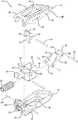
- FIG. 1is a trailing end perspective view of an expandable interbody implant in accordance with an embodiment of the present invention
- FIG. 2is an exploded perspective view of an expandable interbody implant in accordance with the present invention.
- FIG. 3is a side elevational view of one embodiment of an expandable interbody implant in accordance with the present invention, adapted for oblique, anterior, or posterior insertion and placement in a disc space;
- FIG. 4is a top view of the embodiment of FIG. 3 ;
- FIG. 5is a cross-sectional side view of an expandable interbody implant in accordance with the present invention, in an unexpanded position;
- FIG. 6is a cross-sectional side view of an expandable interbody implant in accordance with the present invention, in a partially-expanded position;
- FIG. 7is a side view of an expandable interbody implant in accordance with the present invention, in the partially-expanded position.
- FIG. 8is a side elevational view of another embodiment of an expandable interbody implant in accordance with the present invention.
- FIG. 9is a top view of an expandable interbody implant in accordance with the present invention, having a beveled leading end, inserted into a surgically-corrected disc space between two adjacent vertebrae of a spine, at an oblique angle with respect to an axis extending from an anterior portion of the disc space to a posterior portion of the disc space;
- FIG. 10is a top view of an expandable interbody implant in accordance with the invention, having a substantially vertical planar leading end, inserted into a surgically-corrected disc space between two adjacent vertebrae of a spine, along an axis extending from a posterior portion of the disc space to an anterior portion of the disc space.
- an expandable interbody implant 20includes a leading end 22 and a trailing end 24 .
- Implant 20is adapted for insertion at least into a disc space having a surgically-corrected height between two adjacent vertebrae of a spine.
- Implant 20moreover, is adapted for movement from an unexpanded position to an expanded position.
- Implant 20includes an upper member 26 , having an upper surface 28 extending between leading end 22 and trailing end 24 , with an upper opening 30 defined in upper surface 28 .
- Implant 20further includes a lower member 32 , having a lower surface 34 extending between leading end 22 and trailing end 24 , with a lower opening 36 defined in lower surface 34 .
- a bone graft storage portion 38is preferably provided intermediate leading end 22 and trailing end 24 .
- the bone graft storage portion 38includes a rearward-extending portion 40 , a rear end portion 41 , and a hollow portion 46 sized to receive a selected volume of bone graft material, which may be of a type well-known in the art.
- the side walls of hollow portion 46align with rear portions of the sides of the upper and lower openings 30 and 36 .
- the bone graft materialis adapted to facilitate bone growth between the adjacent vertebrae, via upper opening 30 , hollow portion 46 , and lower opening 36 .
- end portion 41has a generally hemi-cylindrical configuration generally corresponding in shape to a portion of the perimeter of upper opening 30 .
- a translational wall 48is movably provided in a slot 50 provided in bucket portion 38 between rear end portion 41 and hollow portion 46 .
- translational wall 48includes a pair of vertical extensions 52 , slidably mounted in a pair of tracks 54 defined in end portion 41 .
- vertical extensions 52 and tracks 54have a cylindrical configuration, but any configuration, e.g., a rectangular configuration, is within the scope of the invention.
- a pin 56extends through an aperture 58 in the translational wall 48 .
- pin 56inserts through an oval-shaped aperture 60 defined in a side wall 62 of upper member 26 . Pin 56 is adapted to slide in the oval-shaped aperture 60 .
- An actuator 68is adapted to be inserted into and move through an actuator opening 70 in trailing end 24 of implant 20 .
- actuator 68is a threaded actuator having a threaded portion 72 and an actuating end 74 .
- the threads defined on threaded portion 72are configured to threadably engage corresponding threads in actuator opening 70 .
- a threaded actuator and threaded openingare preferred because, once implant 20 is expanded, the threaded engagement between actuator 68 and actuator opening 70 assists in retaining implant 20 in its expanded position.
- the inventionis not limited to use with a threaded actuator or threaded actuator opening.
- Other actuator configurations, and corresponding actuator opening configurations, which are well-known in the artcan be used, and are within the scope of the invention.
- the implantincludes a drive link 80 .
- Drive link 80preferably is configured as an elongated member having a first end 82 , and an opposed second end 90 , and a ramp portion 81 intermediate the two opposing end portions, ramp portion 81 including a face portion 83 terminating in a peak portion 83 a .
- first end 82includes an elongated pin 84 extending through an aperture 86 in the first end, and also through an aperture 88 defined in side wall 62 of upper member 26 , proximate leading end 22 .
- second end 90is movably mounted on an inner surface 92 of lower member 32 .
- the upward movement of upper wall 48 corresponding to the pivotal upward movement of upper member 26raises translational wall 48 to a position where it substantially prevents any of the selected volume of bone graft material packed into a bone graft storage portion 46 from escaping out of the bone graft storage space in the direction of translational wall 48 during expansion of the implant, thereby helping to retain the selected volume of bone graft material within implant 20 .
- Pivotal upward expansion of upper member 26is limited by face portion 83 of the ramp portion 81 of drive link 80 . Face 83 eventually comes into contact with a front surface 49 of the bucket portion 38 , thereby acting as a stop, and preventing further pivotal expansion of the implant 20 .
- the graft volume defined by the bone graft storage portion on the face portion 83 on the “front end,” and the upper and lower endplates of the adjacent vertebral bodies (via the upper and lower openings 30 and 36 respectively),remains substantially constant because, as the top-to-bottom dimension of the implant increases with expansion, the front-to-back dimension of the hollow portion 46 between the translational wall 48 and the face 83 in contact with the front surface 49 decreases simultaneously, thereby reducing formation of pockets in the bone graft material stored in the bone graft storage portion 38 .
- Leading end 22 of implant 20can have different configurations.
- leading end 22has a substantially rounded, bullet-shaped configuration.
- leading end 22has a beveled surface ⁇ defining an oblique angle ⁇ between upper surface 28 and lower surface 34 .
- Oblique angle ⁇preferably is approximately 45°.
- beveled leading end 22 of this embodimentis capable of insertion into the disc space at an oblique angle, preferably 45°, with respect to the axis defined between anterior and posterior portions of the disc space.
- the beveled leading end of this embodimentalso is capable of insertion into the disc space along the axis defined between anterior and posterior portions of the disc.
- leading end 22has a generally planar shape, defining substantial right angles with respect to each of upper and lower surfaces 28 and 34 , respectively. As shown in FIG. 10 , leading end 22 of this embodiment also is configured for insertion of the implant into the disc space at least along the axis defined between anterior and posterior portions of the disc space.
Landscapes
- Health & Medical Sciences (AREA)
- Orthopedic Medicine & Surgery (AREA)
- Engineering & Computer Science (AREA)
- Biomedical Technology (AREA)
- Neurology (AREA)
- Life Sciences & Earth Sciences (AREA)
- General Health & Medical Sciences (AREA)
- Veterinary Medicine (AREA)
- Heart & Thoracic Surgery (AREA)
- Public Health (AREA)
- Animal Behavior & Ethology (AREA)
- Transplantation (AREA)
- Cardiology (AREA)
- Vascular Medicine (AREA)
- Oral & Maxillofacial Surgery (AREA)
- Surgery (AREA)
- Nuclear Medicine, Radiotherapy & Molecular Imaging (AREA)
- Medical Informatics (AREA)
- Molecular Biology (AREA)
- Physical Education & Sports Medicine (AREA)
- Prostheses (AREA)
Abstract
Description
Claims (20)
Priority Applications (2)
| Application Number | Priority Date | Filing Date | Title |
|---|---|---|---|
| US15/926,493US11033402B2 (en) | 2014-11-04 | 2018-03-20 | Expandable interbody implant |
| US17/346,988US11918482B2 (en) | 2014-11-04 | 2021-06-14 | Expandable interbody implant |
Applications Claiming Priority (2)
| Application Number | Priority Date | Filing Date | Title |
|---|---|---|---|
| US14/532,636US9937053B2 (en) | 2014-11-04 | 2014-11-04 | Expandable interbody implant |
| US15/926,493US11033402B2 (en) | 2014-11-04 | 2018-03-20 | Expandable interbody implant |
Related Parent Applications (1)
| Application Number | Title | Priority Date | Filing Date |
|---|---|---|---|
| US14/532,636DivisionUS9937053B2 (en) | 2014-11-04 | 2014-11-04 | Expandable interbody implant |
Related Child Applications (1)
| Application Number | Title | Priority Date | Filing Date |
|---|---|---|---|
| US17/346,988DivisionUS11918482B2 (en) | 2014-11-04 | 2021-06-14 | Expandable interbody implant |
Publications (2)
| Publication Number | Publication Date |
|---|---|
| US20180207003A1 US20180207003A1 (en) | 2018-07-26 |
| US11033402B2true US11033402B2 (en) | 2021-06-15 |
Family
ID=55851400
Family Applications (3)
| Application Number | Title | Priority Date | Filing Date |
|---|---|---|---|
| US14/532,636Active2036-08-22US9937053B2 (en) | 2014-11-04 | 2014-11-04 | Expandable interbody implant |
| US15/926,493Active2035-03-03US11033402B2 (en) | 2014-11-04 | 2018-03-20 | Expandable interbody implant |
| US17/346,988Active2036-01-29US11918482B2 (en) | 2014-11-04 | 2021-06-14 | Expandable interbody implant |
Family Applications Before (1)
| Application Number | Title | Priority Date | Filing Date |
|---|---|---|---|
| US14/532,636Active2036-08-22US9937053B2 (en) | 2014-11-04 | 2014-11-04 | Expandable interbody implant |
Family Applications After (1)
| Application Number | Title | Priority Date | Filing Date |
|---|---|---|---|
| US17/346,988Active2036-01-29US11918482B2 (en) | 2014-11-04 | 2021-06-14 | Expandable interbody implant |
Country Status (6)
| Country | Link |
|---|---|
| US (3) | US9937053B2 (en) |
| EP (1) | EP3215068B1 (en) |
| KR (1) | KR20170078704A (en) |
| CN (1) | CN107106305B (en) |
| AU (1) | AU2015343514B2 (en) |
| WO (1) | WO2016073214A1 (en) |
Cited By (17)
| Publication number | Priority date | Publication date | Assignee | Title |
|---|---|---|---|---|
| US11376134B1 (en) | 2020-11-05 | 2022-07-05 | Warsaw Orthopedic, Inc. | Dual expanding spinal implant, system, and method of use |
| US11395743B1 (en) | 2021-05-04 | 2022-07-26 | Warsaw Orthopedic, Inc. | Externally driven expandable interbody and related methods |
| US11517363B2 (en) | 2020-11-05 | 2022-12-06 | Warsaw Orthopedic, Inc. | Screw driver and complimentary screws |
| US11517443B2 (en) | 2020-11-05 | 2022-12-06 | Warsaw Orthopedic, Inc. | Dual wedge expandable implant, system and method of use |
| US11612499B2 (en) | 2021-06-24 | 2023-03-28 | Warsaw Orthopedic, Inc. | Expandable interbody implant |
| US11638653B2 (en) | 2020-11-05 | 2023-05-02 | Warsaw Orthopedic, Inc. | Surgery instruments with a movable handle |
| US11806250B2 (en) | 2018-02-22 | 2023-11-07 | Warsaw Orthopedic, Inc. | Expandable spinal implant system and method of using same |
| US11833059B2 (en) | 2020-11-05 | 2023-12-05 | Warsaw Orthopedic, Inc. | Expandable inter-body device, expandable plate system, and associated methods |
| US11963881B2 (en) | 2020-11-05 | 2024-04-23 | Warsaw Orthopedic, Inc. | Expandable inter-body device, system, and method |
| US12121453B2 (en) | 2020-11-05 | 2024-10-22 | Warsaw Orthopedic, Inc. | Dual wedge expandable implant with eyelets, system, and method of use |
| US12171439B2 (en) | 2020-11-05 | 2024-12-24 | Warsaw Orthopedic, Inc. | Protected drill |
| US12239544B2 (en) | 2020-11-05 | 2025-03-04 | Warsaw Orthopedic, Inc. | Rhomboid shaped implants |
| US12295865B2 (en) | 2021-06-24 | 2025-05-13 | Warsaw Orthopedic, Inc. | Expandable interbody implant and corresponding inserter |
| US12318308B2 (en) | 2020-11-05 | 2025-06-03 | Warsaw Orthopedic, Inc. | Dual expandable inter-body device |
| US12318307B2 (en) | 2021-07-16 | 2025-06-03 | Blue Ocean Spine Gmbh | Adjustable spinal implants, associated instruments and methods |
| US12414863B2 (en) | 2021-06-24 | 2025-09-16 | Warsaw Orthopedic, Inc. | Expandable interbody implant and corresponding surgical tool |
| US12440349B2 (en) | 2022-02-04 | 2025-10-14 | Warsaw Orthopedic, Inc. | Expandable interbody implant and breakoff screw |
Families Citing this family (88)
| Publication number | Priority date | Publication date | Assignee | Title |
|---|---|---|---|---|
| WO2008070863A2 (en) | 2006-12-07 | 2008-06-12 | Interventional Spine, Inc. | Intervertebral implant |
| US20080161929A1 (en) | 2006-12-29 | 2008-07-03 | Mccormack Bruce | Cervical distraction device |
| US8900307B2 (en) | 2007-06-26 | 2014-12-02 | DePuy Synthes Products, LLC | Highly lordosed fusion cage |
| WO2009089367A2 (en) | 2008-01-09 | 2009-07-16 | Providence Medical Technology, Inc. | Methods and apparatus for accessing and treating the facet joint |
| US8936641B2 (en) | 2008-04-05 | 2015-01-20 | DePuy Synthes Products, LLC | Expandable intervertebral implant |
| US11224521B2 (en) | 2008-06-06 | 2022-01-18 | Providence Medical Technology, Inc. | Cervical distraction/implant delivery device |
| CA2725811A1 (en) | 2008-06-06 | 2009-12-10 | Providence Medical Technology, Inc. | Facet joint implants and delivery tools |
| US8267966B2 (en) | 2008-06-06 | 2012-09-18 | Providence Medical Technology, Inc. | Facet joint implants and delivery tools |
| US9526620B2 (en) | 2009-03-30 | 2016-12-27 | DePuy Synthes Products, Inc. | Zero profile spinal fusion cage |
| US8906028B2 (en) | 2009-09-18 | 2014-12-09 | Spinal Surgical Strategies, Llc | Bone graft delivery device and method of using the same |
| US10973656B2 (en) | 2009-09-18 | 2021-04-13 | Spinal Surgical Strategies, Inc. | Bone graft delivery system and method for using same |
| US10245159B1 (en) | 2009-09-18 | 2019-04-02 | Spinal Surgical Strategies, Llc | Bone graft delivery system and method for using same |
| US10098758B2 (en)* | 2009-10-15 | 2018-10-16 | Globus Medical, Inc. | Expandable fusion device and method of installation thereof |
| US9402732B2 (en) | 2010-10-11 | 2016-08-02 | DePuy Synthes Products, Inc. | Expandable interspinous process spacer implant |
| US9717601B2 (en) | 2013-02-28 | 2017-08-01 | DePuy Synthes Products, Inc. | Expandable intervertebral implant, system, kit and method |
| US9522070B2 (en) | 2013-03-07 | 2016-12-20 | Interventional Spine, Inc. | Intervertebral implant |
| US12193948B2 (en) | 2013-03-13 | 2025-01-14 | Life Spine, Inc. | Expandable implant assembly |
| US10426632B2 (en) | 2013-03-13 | 2019-10-01 | Life Spine, Inc. | Expandable spinal interbody assembly |
| US9987143B2 (en) | 2013-03-15 | 2018-06-05 | Spectrum Spine Ip Holdings, Llc | Expandable inter-body fusion devices and methods |
| US9801734B1 (en)* | 2013-08-09 | 2017-10-31 | Nuvasive, Inc. | Lordotic expandable interbody implant |
| AU2015267055B2 (en) | 2014-05-27 | 2020-04-02 | Christopher U. Phan | Lateral mass fixation implant |
| WO2016069796A1 (en) | 2014-10-28 | 2016-05-06 | Spectrum Spine Ip Holdings, Llc | Expandable, adjustable inter-body fusion devices and methods |
| US10575964B2 (en)* | 2014-10-28 | 2020-03-03 | Spectrum Spine Ip Holdings, Llc | Expandable, adjustable inter-body fusion devices and methods |
| US10363142B2 (en)* | 2014-12-11 | 2019-07-30 | K2M, Inc. | Expandable spinal implants |
| US11426290B2 (en) | 2015-03-06 | 2022-08-30 | DePuy Synthes Products, Inc. | Expandable intervertebral implant, system, kit and method |
| JP6949725B2 (en) | 2015-05-12 | 2021-10-13 | ニューヴェイジヴ,インコーポレイテッド | Expandable lordotic face implant |
| US10842641B2 (en) | 2015-07-14 | 2020-11-24 | Seaspine, Inc. | Expandable implant with deflectable sequence of segments |
| US10500061B2 (en)* | 2015-08-13 | 2019-12-10 | K2M, Inc. | Adjustable spinal implant |
| US10610376B2 (en) | 2015-10-16 | 2020-04-07 | Warsaw Orthopedic, Inc. | Expandable spinal implant system and method |
| US10779955B2 (en)* | 2015-10-26 | 2020-09-22 | Warsaw Orthopedic, Inc. | Spinal implant system and method |
| US9895235B2 (en)* | 2015-12-18 | 2018-02-20 | Warsaw Orthopedic, Inc. | Spinal implant system and method |
| US10076423B2 (en)* | 2016-01-04 | 2018-09-18 | Warsaw Orthopedic, Inc. | Pivoting wedge expanding spinal implant and method of implanting same |
| US10137006B2 (en)* | 2016-01-28 | 2018-11-27 | Warsaw Orthopedic, Inc. | Geared cam expandable interbody implant and method of implanting same |
| CN105796215B (en)* | 2016-05-27 | 2017-12-15 | 瞿玉兴 | Lumbar intervertebral fusion device can be strutted |
| US11510788B2 (en) | 2016-06-28 | 2022-11-29 | Eit Emerging Implant Technologies Gmbh | Expandable, angularly adjustable intervertebral cages |
| EP3474784A2 (en)* | 2016-06-28 | 2019-05-01 | Eit Emerging Implant Technologies GmbH | Expandable and angularly adjustable intervertebral cages with articulating joint |
| US9974662B2 (en)* | 2016-06-29 | 2018-05-22 | Globus Medical, Inc. | Expandable fusion device and method of installation thereof |
| US10052215B2 (en)* | 2016-06-29 | 2018-08-21 | Globus Medical, Inc. | Expandable fusion device and method of installation thereof |
| US10478312B2 (en)* | 2016-10-25 | 2019-11-19 | Institute for Musculoskeletal Science and Education, Ltd. | Implant with protected fusion zones |
| FR3058044A1 (en)* | 2016-10-27 | 2018-05-04 | Ldr Medical | EXPANDABLE INTERSOMATIC CAGE |
| FR3058043B1 (en)* | 2016-10-27 | 2020-11-13 | Ldr Medical | EXPANDABLE INTERSOMATIC CAGE |
| US10238503B2 (en) | 2016-11-01 | 2019-03-26 | Warsaw Orthopedic, Inc. | Expandable spinal implant system with a biased tip and method of using same |
| US10398563B2 (en) | 2017-05-08 | 2019-09-03 | Medos International Sarl | Expandable cage |
| US11871968B2 (en) | 2017-05-19 | 2024-01-16 | Providence Medical Technology, Inc. | Spinal fixation access and delivery system |
| US11344424B2 (en) | 2017-06-14 | 2022-05-31 | Medos International Sarl | Expandable intervertebral implant and related methods |
| US11896494B2 (en) | 2017-07-10 | 2024-02-13 | Life Spine, Inc. | Expandable implant assembly |
| US10575962B2 (en)* | 2017-11-20 | 2020-03-03 | Warsaw Orthopedic, Inc. | Spinal implant |
| US11648128B2 (en) | 2018-01-04 | 2023-05-16 | Providence Medical Technology, Inc. | Facet screw and delivery device |
| US10869769B2 (en)* | 2018-03-06 | 2020-12-22 | Eit Emerging Implant Technologies Gmbh | Intervertebral cages with integrated expansion and angular adjustment mechanism |
| US10695103B2 (en) | 2018-03-29 | 2020-06-30 | Warsaw Orthopedic, Inc. | Motion control and vertebral fixation device |
| US10537447B2 (en) | 2018-03-30 | 2020-01-21 | Warsaw Orthopedic, Inc. | Radiolucent trial |
| US10736756B2 (en) | 2018-03-30 | 2020-08-11 | Warsaw Orthopedic, Inc. | Radiolucent trial |
| AU2019342137A1 (en) | 2018-09-20 | 2021-03-25 | Spinal Elements, Inc. | Spinal implant device |
| WO2020061464A1 (en) | 2018-09-21 | 2020-03-26 | Providence Medical Technology, Inc. | Vertebral joint access and decortication devices and methods of using |
| US11446156B2 (en) | 2018-10-25 | 2022-09-20 | Medos International Sarl | Expandable intervertebral implant, inserter instrument, and related methods |
| FR3093422A1 (en)* | 2019-03-05 | 2020-09-11 | Medicrea International | INTERVERTEBRAL IMPLANT |
| US11253372B2 (en)* | 2019-03-09 | 2022-02-22 | Iorthopedics, Inc. | Universally expanding cages |
| USD933230S1 (en) | 2019-04-15 | 2021-10-12 | Providence Medical Technology, Inc. | Cervical cage |
| US11793651B2 (en)* | 2021-01-04 | 2023-10-24 | Bret Michael Berry | Expandable implant |
| US11382764B2 (en) | 2019-06-10 | 2022-07-12 | Life Spine, Inc. | Expandable implant assembly with compression features |
| US12042395B2 (en) | 2019-06-11 | 2024-07-23 | Life Spine, Inc. | Expandable implant assembly |
| CN110353862A (en)* | 2019-07-22 | 2019-10-22 | 上海锐植医疗器械有限公司 | A kind of Invasive lumbar fusion device |
| CN110464516B (en)* | 2019-09-04 | 2020-05-22 | 北京积水潭医院 | an intervertebral fusion device |
| USD948050S1 (en)* | 2020-02-12 | 2022-04-05 | Warsaw Orthopedic, Inc. | Spinal implant |
| USD945621S1 (en)* | 2020-02-27 | 2022-03-08 | Providence Medical Technology, Inc. | Spinal cage |
| US11690732B2 (en) | 2020-03-05 | 2023-07-04 | Alphatec Spine, Inc. | Expandable lordotic interbodies and related methods |
| US11426286B2 (en) | 2020-03-06 | 2022-08-30 | Eit Emerging Implant Technologies Gmbh | Expandable intervertebral implant |
| CN111329629B (en)* | 2020-03-09 | 2022-03-01 | 中南大学湘雅医院 | An inflatable interbody cage for minimally invasive spine surgery |
| US11857432B2 (en) | 2020-04-13 | 2024-01-02 | Life Spine, Inc. | Expandable implant assembly |
| US11602439B2 (en) | 2020-04-16 | 2023-03-14 | Life Spine, Inc. | Expandable implant assembly |
| US12336917B2 (en) | 2020-05-15 | 2025-06-24 | Life Spine, Inc. | Steerable implant assembly |
| US11602440B2 (en) | 2020-06-25 | 2023-03-14 | Life Spine, Inc. | Expandable implant assembly |
| US11166825B1 (en) | 2020-07-01 | 2021-11-09 | Warsaw Orthopedic, Inc. | Spinal implant |
| JP2023516746A (en)* | 2020-08-07 | 2023-04-20 | アルファテック スパイン, インコーポレイテッド | Deployable lordotic interbody implants and related methods |
| US11554020B2 (en)* | 2020-09-08 | 2023-01-17 | Life Spine, Inc. | Expandable implant with pivoting control assembly |
| US11185421B1 (en) | 2020-09-10 | 2021-11-30 | Warsaw Orthopedic, Inc. | Spinal implant with features facilitating independent expansion of portions thereof and method for use thereof |
| CN114176747B (en)* | 2020-09-15 | 2024-03-08 | 北京纳通医学科技研究院有限公司 | Atlantoaxial joint fusion device |
| US11285014B1 (en) | 2020-11-05 | 2022-03-29 | Warsaw Orthopedic, Inc. | Expandable inter-body device, system, and method |
| US11291554B1 (en) | 2021-05-03 | 2022-04-05 | Medtronic, Inc. | Unibody dual expanding interbody implant |
| US11911284B2 (en) | 2020-11-19 | 2024-02-27 | Spinal Elements, Inc. | Curved expandable interbody devices and deployment tools |
| WO2022133456A1 (en) | 2020-12-17 | 2022-06-23 | Spinal Elements, Inc. | Spinal implant device |
| CN112656551A (en)* | 2020-12-18 | 2021-04-16 | 山东威高骨科材料股份有限公司 | Adjustable artificial vertebral body |
| US11850160B2 (en) | 2021-03-26 | 2023-12-26 | Medos International Sarl | Expandable lordotic intervertebral fusion cage |
| US11752009B2 (en) | 2021-04-06 | 2023-09-12 | Medos International Sarl | Expandable intervertebral fusion cage |
| US12268614B2 (en) | 2021-06-24 | 2025-04-08 | Warsaw Orthopedic, Inc. | Interbody implant with adjusting shims |
| US11730608B2 (en) | 2021-07-13 | 2023-08-22 | Warsaw Orthopedic, Inc. | Monoblock expandable interbody implant |
| US11850163B2 (en) | 2022-02-01 | 2023-12-26 | Warsaw Orthopedic, Inc. | Interbody implant with adjusting shims |
| US12090064B2 (en) | 2022-03-01 | 2024-09-17 | Medos International Sarl | Stabilization members for expandable intervertebral implants, and related systems and methods |
Citations (48)
| Publication number | Priority date | Publication date | Assignee | Title |
|---|---|---|---|---|
| US20020068977A1 (en) | 2000-12-05 | 2002-06-06 | Jackson Roger P. | Anterior variable expandable fusion cage |
| US20020128713A1 (en)* | 1999-08-13 | 2002-09-12 | Bret Ferree | Spinal fusion cage with lordosis correction |
| US20060206207A1 (en) | 2005-01-20 | 2006-09-14 | Dryer Randall F | Expandable spinal fusion cage and associated instrumentation |
| KR100905962B1 (en) | 2008-03-17 | 2009-07-06 | 조철민 | Intervertebral expansion cage device and mounting method |
| US7828849B2 (en) | 2003-02-03 | 2010-11-09 | Warsaw Orthopedic, Inc. | Expanding interbody implant and articulating inserter and method |
| US7850733B2 (en) | 2004-02-10 | 2010-12-14 | Atlas Spine, Inc. | PLIF opposing wedge ramp |
| US7875078B2 (en) | 2004-08-25 | 2011-01-25 | Spine Wave, Inc. | Expandable interbody fusion device |
| US7909869B2 (en) | 2003-08-05 | 2011-03-22 | Flexuspine, Inc. | Artificial spinal unit assemblies |
| US20110172714A1 (en) | 2008-06-27 | 2011-07-14 | K2M, Inc. | System and method for performing spinal surgery |
| US20110172721A1 (en) | 2007-06-29 | 2011-07-14 | Synthes (U.S.A.) | Orthopedic implants for use with precision bone resurfacing instrumentation |
| US8062375B2 (en) | 2009-10-15 | 2011-11-22 | Globus Medical, Inc. | Expandable fusion device and method of installation thereof |
| US8105358B2 (en) | 2008-02-04 | 2012-01-31 | Kyphon Sarl | Medical implants and methods |
| US8105382B2 (en) | 2006-12-07 | 2012-01-31 | Interventional Spine, Inc. | Intervertebral implant |
| US20120029636A1 (en) | 2010-08-02 | 2012-02-02 | Ragab Ashraf A | Bone Cage with Components for Controlled Expansion |
| US8123810B2 (en) | 2003-08-05 | 2012-02-28 | Gordon Charles R | Expandable intervertebral implant with wedged expansion member |
| US20120059470A1 (en) | 2010-09-03 | 2012-03-08 | Mark Weiman | Expandable Fusion Device and Method of Installation Thereof |
| US8133232B2 (en) | 2007-07-17 | 2012-03-13 | Expanding Orthopedics Inc. | Expandable bone device |
| US20120109319A1 (en) | 2009-07-14 | 2012-05-03 | Michael Perisic | Interbody cage |
| US8187332B2 (en) | 2004-11-03 | 2012-05-29 | Mcluen Design, Inc. | Bone fusion device |
| US8382842B2 (en) | 2009-05-14 | 2013-02-26 | Stout Medical Group, L.P. | Expandable support device and method of use |
| US8394145B2 (en) | 2010-02-24 | 2013-03-12 | Globus Medical | Expandable intervertebral spacer and method of posterior insertion thereof |
| US8398713B2 (en) | 2010-09-03 | 2013-03-19 | Globus Medical, Inc. | Expandable fusion device and method of installation thereof |
| US8435298B2 (en) | 2010-09-03 | 2013-05-07 | Globus Medical, Inc. | Expandable fusion device and method of installation thereof |
| US20130144388A1 (en) | 2010-05-28 | 2013-06-06 | Benvenue Medical, Inc. | Disc Space Sizing Devices And Methods Of Using The Same |
| US20130158664A1 (en)* | 2011-12-19 | 2013-06-20 | Warsaw Orthopedic, Inc. | Expandable interbody implant and methods of use |
| US8491659B2 (en) | 2010-09-03 | 2013-07-23 | Globus Medical, Inc. | Expandable fusion device and method of installation thereof |
| US20130190876A1 (en) | 2012-01-19 | 2013-07-25 | Warsaw Orthopedic, Inc. | Expandable interbody implant and methods of use |
| US8518120B2 (en) | 2009-10-15 | 2013-08-27 | Globus Medical, Inc. | Expandable fusion device and method of installation thereof |
| US8523944B2 (en) | 2008-12-31 | 2013-09-03 | Spinex Tec, Llc | Methods and apparatus for vertebral body distraction and fusion employing flexure members |
| CN203183090U (en) | 2013-02-20 | 2013-09-11 | 魏志轩 | Expandable type implantation object of minimally invasive surgery |
| US8556979B2 (en) | 2009-10-15 | 2013-10-15 | Globus Medical, Inc. | Expandable fusion device and method of installation thereof |
| US8628577B1 (en) | 2009-03-19 | 2014-01-14 | Ex Technology, Llc | Stable device for intervertebral distraction and fusion |
| US8628578B2 (en) | 2011-12-19 | 2014-01-14 | Warsaw Orthopedic, Inc. | Expandable interbody implant and methods of use |
| US8632595B2 (en) | 2010-09-03 | 2014-01-21 | Globus Medical, Inc. | Expandable fusion device and method of installation thereof |
| US8663329B2 (en) | 2012-01-28 | 2014-03-04 | Mark J Ernst | Expandable implant for mammalian bony segment stabilization |
| US8685098B2 (en) | 2010-06-25 | 2014-04-01 | Globus Medical, Inc. | Expandable fusion device and method of installation thereof |
| US8709086B2 (en) | 2009-10-15 | 2014-04-29 | Globus Medical, Inc. | Expandable fusion device and method of installation thereof |
| US20140121774A1 (en) | 2009-10-15 | 2014-05-01 | Chad Glerum | Expandable Fusion Device and Method of Installation Thereof |
| CN103830023A (en) | 2012-11-26 | 2014-06-04 | 思邦科技脊柱智慧公司 | Expandable cage for intracorporeal fusion of lumbar vertebrae |
| CN103876865A (en) | 2014-02-21 | 2014-06-25 | 吉林医药学院 | Expandable interbody fusion cage |
| US8778025B2 (en) | 2010-08-02 | 2014-07-15 | Ashraf A. Ragab | Rotatable cam lift for an expandable bone cage |
| US8795366B2 (en) | 2010-01-11 | 2014-08-05 | Innova Spinal Technologies, Llc | Expandable intervertebral implant and associated surgical method |
| AU2014100879A4 (en) | 2014-08-05 | 2014-09-11 | D'Urso, Paul Steven MR | It is the intension of this invention to provide an expandable interbody fusion cage which will expand in all three planes to allow the incorporation of a larger amount of bone graft in the expanded state and facilitate a higher surface area of contact of such bone graft and the fusion cage itself with the vertebral bodies. |
| US8894712B2 (en) | 2010-01-11 | 2014-11-25 | Innova Spinal Technologies, Llc | Expandable intervertebral implant and associated surgical method |
| US8894711B2 (en) | 2010-01-11 | 2014-11-25 | Innova Spinal Technologies, Llc | Expandable intervertebral implant and associated surgical method |
| US8940049B1 (en) | 2014-04-01 | 2015-01-27 | Ex Technology, Llc | Expandable intervertebral cage |
| WO2015063721A1 (en) | 2013-10-31 | 2015-05-07 | Nlt Spine Ltd. | Adjustable implant |
| US9801734B1 (en) | 2013-08-09 | 2017-10-31 | Nuvasive, Inc. | Lordotic expandable interbody implant |
Family Cites Families (2)
| Publication number | Priority date | Publication date | Assignee | Title |
|---|---|---|---|---|
| US9848993B2 (en)* | 2005-04-12 | 2017-12-26 | Nathan C. Moskowitz | Zero-profile expandable intervertebral spacer devices for distraction and spinal fusion and a universal tool for their placement and expansion |
| CA2906531C (en)* | 2013-03-15 | 2020-10-06 | Neuropro Technologies, Inc. | Bodiless bone fusion device, apparatus and method |
- 2014
- 2014-11-04USUS14/532,636patent/US9937053B2/enactiveActive
- 2015
- 2015-10-22WOPCT/US2015/056929patent/WO2016073214A1/enactiveApplication Filing
- 2015-10-22CNCN201580071502.6Apatent/CN107106305B/enactiveActive
- 2015-10-22KRKR1020177013577Apatent/KR20170078704A/ennot_activeCeased
- 2015-10-22EPEP15856782.6Apatent/EP3215068B1/enactiveActive
- 2015-10-22AUAU2015343514Apatent/AU2015343514B2/ennot_activeCeased
- 2018
- 2018-03-20USUS15/926,493patent/US11033402B2/enactiveActive
- 2021
- 2021-06-14USUS17/346,988patent/US11918482B2/enactiveActive
Patent Citations (67)
| Publication number | Priority date | Publication date | Assignee | Title |
|---|---|---|---|---|
| US20020128713A1 (en)* | 1999-08-13 | 2002-09-12 | Bret Ferree | Spinal fusion cage with lordosis correction |
| US6491724B1 (en) | 1999-08-13 | 2002-12-10 | Bret Ferree | Spinal fusion cage with lordosis correction |
| US20020068977A1 (en) | 2000-12-05 | 2002-06-06 | Jackson Roger P. | Anterior variable expandable fusion cage |
| US20110054621A1 (en) | 2003-02-03 | 2011-03-03 | Warsaw Orthopedic, Inc. | Expanding interbody implant and articulating inserter and method |
| US7828849B2 (en) | 2003-02-03 | 2010-11-09 | Warsaw Orthopedic, Inc. | Expanding interbody implant and articulating inserter and method |
| US8123810B2 (en) | 2003-08-05 | 2012-02-28 | Gordon Charles R | Expandable intervertebral implant with wedged expansion member |
| US7909869B2 (en) | 2003-08-05 | 2011-03-22 | Flexuspine, Inc. | Artificial spinal unit assemblies |
| US7850733B2 (en) | 2004-02-10 | 2010-12-14 | Atlas Spine, Inc. | PLIF opposing wedge ramp |
| US7875078B2 (en) | 2004-08-25 | 2011-01-25 | Spine Wave, Inc. | Expandable interbody fusion device |
| US8187332B2 (en) | 2004-11-03 | 2012-05-29 | Mcluen Design, Inc. | Bone fusion device |
| US8403990B2 (en) | 2005-01-20 | 2013-03-26 | Warsaw Orthopedic, Inc. | Expandable spinal fusion cage and associated instrumentation |
| US20060206207A1 (en) | 2005-01-20 | 2006-09-14 | Dryer Randall F | Expandable spinal fusion cage and associated instrumentation |
| US8105382B2 (en) | 2006-12-07 | 2012-01-31 | Interventional Spine, Inc. | Intervertebral implant |
| US8568481B2 (en) | 2006-12-07 | 2013-10-29 | Interventional Spine, Inc. | Intervertebral implant |
| US20110172721A1 (en) | 2007-06-29 | 2011-07-14 | Synthes (U.S.A.) | Orthopedic implants for use with precision bone resurfacing instrumentation |
| US8133232B2 (en) | 2007-07-17 | 2012-03-13 | Expanding Orthopedics Inc. | Expandable bone device |
| US8105358B2 (en) | 2008-02-04 | 2012-01-31 | Kyphon Sarl | Medical implants and methods |
| KR100905962B1 (en) | 2008-03-17 | 2009-07-06 | 조철민 | Intervertebral expansion cage device and mounting method |
| US20110172714A1 (en) | 2008-06-27 | 2011-07-14 | K2M, Inc. | System and method for performing spinal surgery |
| US8523944B2 (en) | 2008-12-31 | 2013-09-03 | Spinex Tec, Llc | Methods and apparatus for vertebral body distraction and fusion employing flexure members |
| US8628577B1 (en) | 2009-03-19 | 2014-01-14 | Ex Technology, Llc | Stable device for intervertebral distraction and fusion |
| US8382842B2 (en) | 2009-05-14 | 2013-02-26 | Stout Medical Group, L.P. | Expandable support device and method of use |
| US20120109319A1 (en) | 2009-07-14 | 2012-05-03 | Michael Perisic | Interbody cage |
| US20140121774A1 (en) | 2009-10-15 | 2014-05-01 | Chad Glerum | Expandable Fusion Device and Method of Installation Thereof |
| US8062375B2 (en) | 2009-10-15 | 2011-11-22 | Globus Medical, Inc. | Expandable fusion device and method of installation thereof |
| US20120158146A1 (en) | 2009-10-15 | 2012-06-21 | Chad Glerum | Expandable Fusion Device and Method of Installation Thereof |
| US20120158148A1 (en) | 2009-10-15 | 2012-06-21 | Chad Glerum | Expandable Fusion Device and Method of Installation Thereof |
| US20120150304A1 (en) | 2009-10-15 | 2012-06-14 | Chad Glerum | Expandable Fusion Device and Method of Installation Thereof |
| US8888854B2 (en) | 2009-10-15 | 2014-11-18 | Globus Medical, Inc. | Expandable fusion device and method of installation thereof |
| US8888853B2 (en) | 2009-10-15 | 2014-11-18 | Globus Medical Inc. | Expandable fusion device and method of installation thereof |
| US20120150305A1 (en) | 2009-10-15 | 2012-06-14 | Chad Glerum | Expandable Fusion Device and Method of Installation Thereof |
| US20140324171A1 (en) | 2009-10-15 | 2014-10-30 | Globus Medical, Inc | Expandable Fusion Device and Method of Installation Thereof |
| US8926704B2 (en) | 2009-10-15 | 2015-01-06 | Globus Medical, Inc. | Expandable fusion device and method of installation thereof |
| US9039771B2 (en) | 2009-10-15 | 2015-05-26 | Globus Medical, Inc | Expandable fusion device and method of installation thereof |
| US8709086B2 (en) | 2009-10-15 | 2014-04-29 | Globus Medical, Inc. | Expandable fusion device and method of installation thereof |
| US20120158147A1 (en) | 2009-10-15 | 2012-06-21 | Chad Glerum | Expandable Fusion Device and Method of Installation Thereof |
| US8518120B2 (en) | 2009-10-15 | 2013-08-27 | Globus Medical, Inc. | Expandable fusion device and method of installation thereof |
| US20120035729A1 (en) | 2009-10-15 | 2012-02-09 | Chad Glerum | Expandable Fusion Device and Method of Installation Thereof |
| US9119730B2 (en) | 2009-10-15 | 2015-09-01 | Globus Medical, Inc. | Expandable fusion device and method of installation thereof |
| US8556979B2 (en) | 2009-10-15 | 2013-10-15 | Globus Medical, Inc. | Expandable fusion device and method of installation thereof |
| US8795366B2 (en) | 2010-01-11 | 2014-08-05 | Innova Spinal Technologies, Llc | Expandable intervertebral implant and associated surgical method |
| US8894712B2 (en) | 2010-01-11 | 2014-11-25 | Innova Spinal Technologies, Llc | Expandable intervertebral implant and associated surgical method |
| US8894711B2 (en) | 2010-01-11 | 2014-11-25 | Innova Spinal Technologies, Llc | Expandable intervertebral implant and associated surgical method |
| US8394145B2 (en) | 2010-02-24 | 2013-03-12 | Globus Medical | Expandable intervertebral spacer and method of posterior insertion thereof |
| US20130144388A1 (en) | 2010-05-28 | 2013-06-06 | Benvenue Medical, Inc. | Disc Space Sizing Devices And Methods Of Using The Same |
| US8679183B2 (en) | 2010-06-25 | 2014-03-25 | Globus Medical | Expandable fusion device and method of installation thereof |
| US8685098B2 (en) | 2010-06-25 | 2014-04-01 | Globus Medical, Inc. | Expandable fusion device and method of installation thereof |
| US20120029636A1 (en) | 2010-08-02 | 2012-02-02 | Ragab Ashraf A | Bone Cage with Components for Controlled Expansion |
| US8778025B2 (en) | 2010-08-02 | 2014-07-15 | Ashraf A. Ragab | Rotatable cam lift for an expandable bone cage |
| US8491659B2 (en) | 2010-09-03 | 2013-07-23 | Globus Medical, Inc. | Expandable fusion device and method of installation thereof |
| US20120059470A1 (en) | 2010-09-03 | 2012-03-08 | Mark Weiman | Expandable Fusion Device and Method of Installation Thereof |
| US8632595B2 (en) | 2010-09-03 | 2014-01-21 | Globus Medical, Inc. | Expandable fusion device and method of installation thereof |
| US8435298B2 (en) | 2010-09-03 | 2013-05-07 | Globus Medical, Inc. | Expandable fusion device and method of installation thereof |
| US8398713B2 (en) | 2010-09-03 | 2013-03-19 | Globus Medical, Inc. | Expandable fusion device and method of installation thereof |
| US20130158664A1 (en)* | 2011-12-19 | 2013-06-20 | Warsaw Orthopedic, Inc. | Expandable interbody implant and methods of use |
| CN104023675A (en) | 2011-12-19 | 2014-09-03 | 华沙整形外科股份有限公司 | Expandable Interbody Implant And Methods Of Use |
| US8628578B2 (en) | 2011-12-19 | 2014-01-14 | Warsaw Orthopedic, Inc. | Expandable interbody implant and methods of use |
| US20130190876A1 (en) | 2012-01-19 | 2013-07-25 | Warsaw Orthopedic, Inc. | Expandable interbody implant and methods of use |
| US8663329B2 (en) | 2012-01-28 | 2014-03-04 | Mark J Ernst | Expandable implant for mammalian bony segment stabilization |
| CN103830023A (en) | 2012-11-26 | 2014-06-04 | 思邦科技脊柱智慧公司 | Expandable cage for intracorporeal fusion of lumbar vertebrae |
| CN203183090U (en) | 2013-02-20 | 2013-09-11 | 魏志轩 | Expandable type implantation object of minimally invasive surgery |
| US9801734B1 (en) | 2013-08-09 | 2017-10-31 | Nuvasive, Inc. | Lordotic expandable interbody implant |
| WO2015063721A1 (en) | 2013-10-31 | 2015-05-07 | Nlt Spine Ltd. | Adjustable implant |
| US20160250034A1 (en) | 2013-10-31 | 2016-09-01 | Nlt Spine Ltd. | Adjustable implant |
| CN103876865A (en) | 2014-02-21 | 2014-06-25 | 吉林医药学院 | Expandable interbody fusion cage |
| US8940049B1 (en) | 2014-04-01 | 2015-01-27 | Ex Technology, Llc | Expandable intervertebral cage |
| AU2014100879A4 (en) | 2014-08-05 | 2014-09-11 | D'Urso, Paul Steven MR | It is the intension of this invention to provide an expandable interbody fusion cage which will expand in all three planes to allow the incorporation of a larger amount of bone graft in the expanded state and facilitate a higher surface area of contact of such bone graft and the fusion cage itself with the vertebral bodies. |
Non-Patent Citations (5)
| Title |
|---|
| European Search Report dated May 4, 2018 for EP15856782.6. |
| Examination Report dated Oct. 28, 2017 for Australian Application No. 2015343514. |
| International Search Report and Written Opinion dated Feb. 2, 2016 for PCT/US2015/056929. |
| Office Action (English Translation) dated Jul. 12, 2018 for Chinese Application No. 201580071502.6. |
| Office Action dated Jul. 12, 2018 for Chinese Application No. 201580071502.6. |
Cited By (23)
| Publication number | Priority date | Publication date | Assignee | Title |
|---|---|---|---|---|
| US11806250B2 (en) | 2018-02-22 | 2023-11-07 | Warsaw Orthopedic, Inc. | Expandable spinal implant system and method of using same |
| US12036132B2 (en) | 2018-02-22 | 2024-07-16 | Warsaw Orthopedic, Inc. | Expandable spinal implant system and method of using same |
| US12171439B2 (en) | 2020-11-05 | 2024-12-24 | Warsaw Orthopedic, Inc. | Protected drill |
| US12053392B2 (en) | 2020-11-05 | 2024-08-06 | Warsaw Orthopedic, Inc. | Expandable inter-body device, expandable plate system, and associated methods |
| US11564724B2 (en) | 2020-11-05 | 2023-01-31 | Warsaw Orthopedic, Inc. | Expandable inter-body device, system and method |
| US12364529B2 (en) | 2020-11-05 | 2025-07-22 | Warsaw Orthopedic, Inc. | Expandable inter-body device, system, and method |
| US11617658B2 (en) | 2020-11-05 | 2023-04-04 | Warsaw Orthopedic, Inc. | Expandable inter-body device, system and method |
| US11638653B2 (en) | 2020-11-05 | 2023-05-02 | Warsaw Orthopedic, Inc. | Surgery instruments with a movable handle |
| US11517363B2 (en) | 2020-11-05 | 2022-12-06 | Warsaw Orthopedic, Inc. | Screw driver and complimentary screws |
| US11833059B2 (en) | 2020-11-05 | 2023-12-05 | Warsaw Orthopedic, Inc. | Expandable inter-body device, expandable plate system, and associated methods |
| US11963881B2 (en) | 2020-11-05 | 2024-04-23 | Warsaw Orthopedic, Inc. | Expandable inter-body device, system, and method |
| US11969196B2 (en) | 2020-11-05 | 2024-04-30 | Warsaw Orthopedic, Inc. | Expandable inter-body device, system, and method |
| US12318308B2 (en) | 2020-11-05 | 2025-06-03 | Warsaw Orthopedic, Inc. | Dual expandable inter-body device |
| US11517443B2 (en) | 2020-11-05 | 2022-12-06 | Warsaw Orthopedic, Inc. | Dual wedge expandable implant, system and method of use |
| US12121453B2 (en) | 2020-11-05 | 2024-10-22 | Warsaw Orthopedic, Inc. | Dual wedge expandable implant with eyelets, system, and method of use |
| US11376134B1 (en) | 2020-11-05 | 2022-07-05 | Warsaw Orthopedic, Inc. | Dual expanding spinal implant, system, and method of use |
| US12239544B2 (en) | 2020-11-05 | 2025-03-04 | Warsaw Orthopedic, Inc. | Rhomboid shaped implants |
| US11395743B1 (en) | 2021-05-04 | 2022-07-26 | Warsaw Orthopedic, Inc. | Externally driven expandable interbody and related methods |
| US12295865B2 (en) | 2021-06-24 | 2025-05-13 | Warsaw Orthopedic, Inc. | Expandable interbody implant and corresponding inserter |
| US11612499B2 (en) | 2021-06-24 | 2023-03-28 | Warsaw Orthopedic, Inc. | Expandable interbody implant |
| US12414863B2 (en) | 2021-06-24 | 2025-09-16 | Warsaw Orthopedic, Inc. | Expandable interbody implant and corresponding surgical tool |
| US12318307B2 (en) | 2021-07-16 | 2025-06-03 | Blue Ocean Spine Gmbh | Adjustable spinal implants, associated instruments and methods |
| US12440349B2 (en) | 2022-02-04 | 2025-10-14 | Warsaw Orthopedic, Inc. | Expandable interbody implant and breakoff screw |
Also Published As
| Publication number | Publication date |
|---|---|
| US20210298916A1 (en) | 2021-09-30 |
| US11918482B2 (en) | 2024-03-05 |
| CN107106305B (en) | 2019-04-12 |
| US20160120660A1 (en) | 2016-05-05 |
| CN107106305A (en) | 2017-08-29 |
| US20180207003A1 (en) | 2018-07-26 |
| EP3215068A1 (en) | 2017-09-13 |
| AU2015343514B2 (en) | 2018-08-30 |
| EP3215068B1 (en) | 2019-09-04 |
| KR20170078704A (en) | 2017-07-07 |
| AU2015343514A1 (en) | 2017-06-01 |
| US9937053B2 (en) | 2018-04-10 |
| EP3215068A4 (en) | 2018-05-30 |
| WO2016073214A1 (en) | 2016-05-12 |
Similar Documents
| Publication | Publication Date | Title |
|---|---|---|
| US11918482B2 (en) | Expandable interbody implant | |
| US11129731B2 (en) | Pivoting wedge expanding spinal implant and method of implanting same | |
| US7850734B2 (en) | Sliding intervertebral implant | |
| US20230248534A1 (en) | Expandable fusion device and method of installation thereof | |
| US11065129B2 (en) | Expandable intervertebral fusion device | |
| US20250143891A1 (en) | Lordotic expandable interbody implant and method of using same | |
| US10463502B2 (en) | Expandable intervertebral device and tool for inserting same | |
| JP4966964B2 (en) | Inflatable spinal graft | |
| US9713536B2 (en) | Expandable spinal implant and method of implanting same | |
| US8579976B2 (en) | Expandable cage for vertebral surgery involving lumbar intersomatic fusion by a transforaminal posterior approach | |
| KR20150118098A (en) | Infinitely Vertically Adjustable Intervertebral Fusion Implant | |
| EP3766460A1 (en) | Expandable implant and insertion tool | |
| JP2007513718A (en) | Expandable intervertebral implant | |
| US20170119538A1 (en) | Expandable spinal fusion device | |
| JP2015536774A (en) | Intervertebral fusion implant capable of lateral expansion | |
| KR20200011636A (en) | Space expanding intervertebral fusion cage device | |
| KR20230103292A (en) | Intervertebral fusion device | |
| JP4796623B2 (en) | Inflatable intervertebral graft |
Legal Events
| Date | Code | Title | Description |
|---|---|---|---|
| AS | Assignment | Owner name:WARSAW ORTHOPEDIC, INC., INDIANA Free format text:ASSIGNMENT OF ASSIGNORS INTEREST;ASSIGNORS:MELKENT, ANTHONY J.;ARMSTRONG, WILLIAM D.;PALMATIER, STANLEY T.;SIGNING DATES FROM 20141030 TO 20141103;REEL/FRAME:045657/0126 | |
| FEPP | Fee payment procedure | Free format text:ENTITY STATUS SET TO UNDISCOUNTED (ORIGINAL EVENT CODE: BIG.); ENTITY STATUS OF PATENT OWNER: LARGE ENTITY | |
| STPP | Information on status: patent application and granting procedure in general | Free format text:DOCKETED NEW CASE - READY FOR EXAMINATION | |
| STPP | Information on status: patent application and granting procedure in general | Free format text:NON FINAL ACTION MAILED | |
| STPP | Information on status: patent application and granting procedure in general | Free format text:RESPONSE TO NON-FINAL OFFICE ACTION ENTERED AND FORWARDED TO EXAMINER | |
| STPP | Information on status: patent application and granting procedure in general | Free format text:FINAL REJECTION MAILED | |
| STPP | Information on status: patent application and granting procedure in general | Free format text:DOCKETED NEW CASE - READY FOR EXAMINATION | |
| STPP | Information on status: patent application and granting procedure in general | Free format text:NOTICE OF ALLOWANCE MAILED -- APPLICATION RECEIVED IN OFFICE OF PUBLICATIONS | |
| STPP | Information on status: patent application and granting procedure in general | Free format text:NOTICE OF ALLOWANCE MAILED -- APPLICATION RECEIVED IN OFFICE OF PUBLICATIONS | |
| STPP | Information on status: patent application and granting procedure in general | Free format text:PUBLICATIONS -- ISSUE FEE PAYMENT RECEIVED | |
| STPP | Information on status: patent application and granting procedure in general | Free format text:PUBLICATIONS -- ISSUE FEE PAYMENT VERIFIED | |
| STCF | Information on status: patent grant | Free format text:PATENTED CASE | |
| MAFP | Maintenance fee payment | Free format text:PAYMENT OF MAINTENANCE FEE, 4TH YEAR, LARGE ENTITY (ORIGINAL EVENT CODE: M1551); ENTITY STATUS OF PATENT OWNER: LARGE ENTITY Year of fee payment:4 |