US11033399B2 - Shoulder arthroplasty implant system - Google Patents
Shoulder arthroplasty implant systemDownload PDFInfo
- Publication number
- US11033399B2 US11033399B2US16/208,324US201816208324AUS11033399B2US 11033399 B2US11033399 B2US 11033399B2US 201816208324 AUS201816208324 AUS 201816208324AUS 11033399 B2US11033399 B2US 11033399B2
- Authority
- US
- United States
- Prior art keywords
- implant
- stem
- humerus
- taper
- distal
- Prior art date
- Legal status (The legal status is an assumption and is not a legal conclusion. Google has not performed a legal analysis and makes no representation as to the accuracy of the status listed.)
- Active
Links
- 239000007943implantSubstances0.000titleclaimsabstractdescription91
- 238000011882arthroplastyMethods0.000titleclaimsabstractdescription27
- 210000002758humerusAnatomy0.000claimsabstractdescription56
- 210000003275diaphysisAnatomy0.000claimsabstractdescription11
- 210000000988bone and boneAnatomy0.000claimsdescription66
- 238000000034methodMethods0.000claimsdescription30
- 238000002271resectionMethods0.000claimsdescription14
- 230000008878couplingEffects0.000claimsdescription10
- 238000010168coupling processMethods0.000claimsdescription10
- 238000005859coupling reactionMethods0.000claimsdescription10
- 230000001054cortical effectEffects0.000claimsdescription7
- 230000003247decreasing effectEffects0.000claimsdescription4
- 238000001125extrusionMethods0.000description31
- 238000013461designMethods0.000description25
- 241001653121GlenoidesSpecies0.000description10
- 238000000576coating methodMethods0.000description9
- 210000004095humeral headAnatomy0.000description9
- 210000003484anatomyAnatomy0.000description8
- 239000011248coating agentSubstances0.000description7
- 238000002513implantationMethods0.000description6
- 230000008468bone growthEffects0.000description5
- 238000005056compactionMethods0.000description5
- 238000003780insertionMethods0.000description5
- 230000037431insertionEffects0.000description5
- 238000001356surgical procedureMethods0.000description5
- 206010065687Bone lossDiseases0.000description4
- 206010017076FractureDiseases0.000description4
- 230000008901benefitEffects0.000description4
- 230000033001locomotionEffects0.000description4
- 210000000513rotator cuffAnatomy0.000description4
- 230000007423decreaseEffects0.000description3
- 229920000642polymerPolymers0.000description3
- 238000004513sizingMethods0.000description3
- 208000010392Bone FracturesDiseases0.000description2
- 238000005520cutting processMethods0.000description2
- 210000002745epiphysisAnatomy0.000description2
- 230000013011matingEffects0.000description2
- 210000003205muscleAnatomy0.000description2
- 210000000323shoulder jointAnatomy0.000description2
- 210000004872soft tissueAnatomy0.000description2
- 210000002435tendonAnatomy0.000description2
- 208000002103Shoulder FracturesDiseases0.000description1
- RTAQQCXQSZGOHL-UHFFFAOYSA-NTitaniumChemical compound[Ti]RTAQQCXQSZGOHL-UHFFFAOYSA-N0.000description1
- 229920010741Ultra High Molecular Weight Polyethylene (UHMWPE)Polymers0.000description1
- 210000001188articular cartilageAnatomy0.000description1
- 230000002146bilateral effectEffects0.000description1
- 239000008280bloodSubstances0.000description1
- 210000004369bloodAnatomy0.000description1
- 239000004568cementSubstances0.000description1
- 230000003412degenerative effectEffects0.000description1
- 210000000852deltoid muscleAnatomy0.000description1
- 201000010099diseaseDiseases0.000description1
- 208000037265diseases, disorders, signs and symptomsDiseases0.000description1
- 230000000694effectsEffects0.000description1
- 229910052588hydroxylapatiteInorganic materials0.000description1
- 230000006872improvementEffects0.000description1
- 238000010348incorporationMethods0.000description1
- 238000009434installationMethods0.000description1
- 230000003993interactionEffects0.000description1
- 238000004519manufacturing processMethods0.000description1
- 239000000463materialSubstances0.000description1
- 230000007246mechanismEffects0.000description1
- 238000012986modificationMethods0.000description1
- 230000004048modificationEffects0.000description1
- 201000008482osteoarthritisDiseases0.000description1
- XYJRXVWERLGGKC-UHFFFAOYSA-Dpentacalcium;hydroxide;triphosphateChemical compound[OH-].[Ca+2].[Ca+2].[Ca+2].[Ca+2].[Ca+2].[O-]P([O-])([O-])=O.[O-]P([O-])([O-])=O.[O-]P([O-])([O-])=OXYJRXVWERLGGKC-UHFFFAOYSA-D0.000description1
- 238000002360preparation methodMethods0.000description1
- 230000008569processEffects0.000description1
- 239000007921spraySubstances0.000description1
- 230000007480spreadingEffects0.000description1
- 238000003892spreadingMethods0.000description1
- 238000013179statistical modelMethods0.000description1
- 229910052719titaniumInorganic materials0.000description1
- 239000010936titaniumSubstances0.000description1
- 230000007704transitionEffects0.000description1
Images


Classifications
- A—HUMAN NECESSITIES
- A61—MEDICAL OR VETERINARY SCIENCE; HYGIENE
- A61F—FILTERS IMPLANTABLE INTO BLOOD VESSELS; PROSTHESES; DEVICES PROVIDING PATENCY TO, OR PREVENTING COLLAPSING OF, TUBULAR STRUCTURES OF THE BODY, e.g. STENTS; ORTHOPAEDIC, NURSING OR CONTRACEPTIVE DEVICES; FOMENTATION; TREATMENT OR PROTECTION OF EYES OR EARS; BANDAGES, DRESSINGS OR ABSORBENT PADS; FIRST-AID KITS
- A61F2/00—Filters implantable into blood vessels; Prostheses, i.e. artificial substitutes or replacements for parts of the body; Appliances for connecting them with the body; Devices providing patency to, or preventing collapsing of, tubular structures of the body, e.g. stents
- A61F2/02—Prostheses implantable into the body
- A61F2/30—Joints
- A61F2/40—Joints for shoulders
- A—HUMAN NECESSITIES
- A61—MEDICAL OR VETERINARY SCIENCE; HYGIENE
- A61B—DIAGNOSIS; SURGERY; IDENTIFICATION
- A61B17/00—Surgical instruments, devices or methods
- A61B17/16—Instruments for performing osteoclasis; Drills or chisels for bones; Trepans
- A61B17/1659—Surgical rasps, files, planes, or scrapers
- A—HUMAN NECESSITIES
- A61—MEDICAL OR VETERINARY SCIENCE; HYGIENE
- A61B—DIAGNOSIS; SURGERY; IDENTIFICATION
- A61B17/00—Surgical instruments, devices or methods
- A61B17/16—Instruments for performing osteoclasis; Drills or chisels for bones; Trepans
- A61B17/1662—Instruments for performing osteoclasis; Drills or chisels for bones; Trepans for particular parts of the body
- A61B17/1684—Instruments for performing osteoclasis; Drills or chisels for bones; Trepans for particular parts of the body for the shoulder
- A—HUMAN NECESSITIES
- A61—MEDICAL OR VETERINARY SCIENCE; HYGIENE
- A61B—DIAGNOSIS; SURGERY; IDENTIFICATION
- A61B17/00—Surgical instruments, devices or methods
- A61B17/16—Instruments for performing osteoclasis; Drills or chisels for bones; Trepans
- A61B17/17—Guides or aligning means for drills, mills, pins or wires
- A61B17/1739—Guides or aligning means for drills, mills, pins or wires specially adapted for particular parts of the body
- A61B17/1778—Guides or aligning means for drills, mills, pins or wires specially adapted for particular parts of the body for the shoulder
- A—HUMAN NECESSITIES
- A61—MEDICAL OR VETERINARY SCIENCE; HYGIENE
- A61B—DIAGNOSIS; SURGERY; IDENTIFICATION
- A61B17/00—Surgical instruments, devices or methods
- A61B17/56—Surgical instruments or methods for treatment of bones or joints; Devices specially adapted therefor
- A61B17/58—Surgical instruments or methods for treatment of bones or joints; Devices specially adapted therefor for osteosynthesis, e.g. bone plates, screws or setting implements
- A61B17/68—Internal fixation devices, including fasteners and spinal fixators, even if a part thereof projects from the skin
- A—HUMAN NECESSITIES
- A61—MEDICAL OR VETERINARY SCIENCE; HYGIENE
- A61F—FILTERS IMPLANTABLE INTO BLOOD VESSELS; PROSTHESES; DEVICES PROVIDING PATENCY TO, OR PREVENTING COLLAPSING OF, TUBULAR STRUCTURES OF THE BODY, e.g. STENTS; ORTHOPAEDIC, NURSING OR CONTRACEPTIVE DEVICES; FOMENTATION; TREATMENT OR PROTECTION OF EYES OR EARS; BANDAGES, DRESSINGS OR ABSORBENT PADS; FIRST-AID KITS
- A61F2/00—Filters implantable into blood vessels; Prostheses, i.e. artificial substitutes or replacements for parts of the body; Appliances for connecting them with the body; Devices providing patency to, or preventing collapsing of, tubular structures of the body, e.g. stents
- A61F2/02—Prostheses implantable into the body
- A61F2/28—Bones
- A—HUMAN NECESSITIES
- A61—MEDICAL OR VETERINARY SCIENCE; HYGIENE
- A61F—FILTERS IMPLANTABLE INTO BLOOD VESSELS; PROSTHESES; DEVICES PROVIDING PATENCY TO, OR PREVENTING COLLAPSING OF, TUBULAR STRUCTURES OF THE BODY, e.g. STENTS; ORTHOPAEDIC, NURSING OR CONTRACEPTIVE DEVICES; FOMENTATION; TREATMENT OR PROTECTION OF EYES OR EARS; BANDAGES, DRESSINGS OR ABSORBENT PADS; FIRST-AID KITS
- A61F2/00—Filters implantable into blood vessels; Prostheses, i.e. artificial substitutes or replacements for parts of the body; Appliances for connecting them with the body; Devices providing patency to, or preventing collapsing of, tubular structures of the body, e.g. stents
- A61F2/02—Prostheses implantable into the body
- A61F2/30—Joints
- A61F2/40—Joints for shoulders
- A61F2/4003—Replacing only the epiphyseal or metaphyseal parts of the humerus, i.e. endoprosthesis not comprising an entire humeral shaft
- A—HUMAN NECESSITIES
- A61—MEDICAL OR VETERINARY SCIENCE; HYGIENE
- A61F—FILTERS IMPLANTABLE INTO BLOOD VESSELS; PROSTHESES; DEVICES PROVIDING PATENCY TO, OR PREVENTING COLLAPSING OF, TUBULAR STRUCTURES OF THE BODY, e.g. STENTS; ORTHOPAEDIC, NURSING OR CONTRACEPTIVE DEVICES; FOMENTATION; TREATMENT OR PROTECTION OF EYES OR EARS; BANDAGES, DRESSINGS OR ABSORBENT PADS; FIRST-AID KITS
- A61F2/00—Filters implantable into blood vessels; Prostheses, i.e. artificial substitutes or replacements for parts of the body; Appliances for connecting them with the body; Devices providing patency to, or preventing collapsing of, tubular structures of the body, e.g. stents
- A61F2/02—Prostheses implantable into the body
- A61F2/30—Joints
- A61F2/40—Joints for shoulders
- A61F2/4059—Humeral shafts
- A—HUMAN NECESSITIES
- A61—MEDICAL OR VETERINARY SCIENCE; HYGIENE
- A61F—FILTERS IMPLANTABLE INTO BLOOD VESSELS; PROSTHESES; DEVICES PROVIDING PATENCY TO, OR PREVENTING COLLAPSING OF, TUBULAR STRUCTURES OF THE BODY, e.g. STENTS; ORTHOPAEDIC, NURSING OR CONTRACEPTIVE DEVICES; FOMENTATION; TREATMENT OR PROTECTION OF EYES OR EARS; BANDAGES, DRESSINGS OR ABSORBENT PADS; FIRST-AID KITS
- A61F2/00—Filters implantable into blood vessels; Prostheses, i.e. artificial substitutes or replacements for parts of the body; Appliances for connecting them with the body; Devices providing patency to, or preventing collapsing of, tubular structures of the body, e.g. stents
- A61F2/02—Prostheses implantable into the body
- A61F2/30—Joints
- A61F2/46—Special tools for implanting artificial joints
- A61F2/4603—Special tools for implanting artificial joints for insertion or extraction of endoprosthetic joints or of accessories thereof
- A61F2/4612—Special tools for implanting artificial joints for insertion or extraction of endoprosthetic joints or of accessories thereof of shoulders
- A—HUMAN NECESSITIES
- A61—MEDICAL OR VETERINARY SCIENCE; HYGIENE
- A61F—FILTERS IMPLANTABLE INTO BLOOD VESSELS; PROSTHESES; DEVICES PROVIDING PATENCY TO, OR PREVENTING COLLAPSING OF, TUBULAR STRUCTURES OF THE BODY, e.g. STENTS; ORTHOPAEDIC, NURSING OR CONTRACEPTIVE DEVICES; FOMENTATION; TREATMENT OR PROTECTION OF EYES OR EARS; BANDAGES, DRESSINGS OR ABSORBENT PADS; FIRST-AID KITS
- A61F2/00—Filters implantable into blood vessels; Prostheses, i.e. artificial substitutes or replacements for parts of the body; Appliances for connecting them with the body; Devices providing patency to, or preventing collapsing of, tubular structures of the body, e.g. stents
- A61F2/02—Prostheses implantable into the body
- A61F2/28—Bones
- A61F2002/2835—Bone graft implants for filling a bony defect or an endoprosthesis cavity, e.g. by synthetic material or biological material
- A—HUMAN NECESSITIES
- A61—MEDICAL OR VETERINARY SCIENCE; HYGIENE
- A61F—FILTERS IMPLANTABLE INTO BLOOD VESSELS; PROSTHESES; DEVICES PROVIDING PATENCY TO, OR PREVENTING COLLAPSING OF, TUBULAR STRUCTURES OF THE BODY, e.g. STENTS; ORTHOPAEDIC, NURSING OR CONTRACEPTIVE DEVICES; FOMENTATION; TREATMENT OR PROTECTION OF EYES OR EARS; BANDAGES, DRESSINGS OR ABSORBENT PADS; FIRST-AID KITS
- A61F2/00—Filters implantable into blood vessels; Prostheses, i.e. artificial substitutes or replacements for parts of the body; Appliances for connecting them with the body; Devices providing patency to, or preventing collapsing of, tubular structures of the body, e.g. stents
- A61F2/02—Prostheses implantable into the body
- A61F2/30—Joints
- A61F2002/30001—Additional features of subject-matter classified in A61F2/28, A61F2/30 and subgroups thereof
- A61F2002/30316—The prosthesis having different structural features at different locations within the same prosthesis; Connections between prosthetic parts; Special structural features of bone or joint prostheses not otherwise provided for
- A61F2002/30329—Connections or couplings between prosthetic parts, e.g. between modular parts; Connecting elements
- A61F2002/30331—Connections or couplings between prosthetic parts, e.g. between modular parts; Connecting elements made by longitudinally pushing a protrusion into a complementarily-shaped recess, e.g. held by friction fit
- A61F2002/30332—Conically- or frustoconically-shaped protrusion and recess
- A—HUMAN NECESSITIES
- A61—MEDICAL OR VETERINARY SCIENCE; HYGIENE
- A61F—FILTERS IMPLANTABLE INTO BLOOD VESSELS; PROSTHESES; DEVICES PROVIDING PATENCY TO, OR PREVENTING COLLAPSING OF, TUBULAR STRUCTURES OF THE BODY, e.g. STENTS; ORTHOPAEDIC, NURSING OR CONTRACEPTIVE DEVICES; FOMENTATION; TREATMENT OR PROTECTION OF EYES OR EARS; BANDAGES, DRESSINGS OR ABSORBENT PADS; FIRST-AID KITS
- A61F2/00—Filters implantable into blood vessels; Prostheses, i.e. artificial substitutes or replacements for parts of the body; Appliances for connecting them with the body; Devices providing patency to, or preventing collapsing of, tubular structures of the body, e.g. stents
- A61F2/02—Prostheses implantable into the body
- A61F2/30—Joints
- A61F2002/30001—Additional features of subject-matter classified in A61F2/28, A61F2/30 and subgroups thereof
- A61F2002/30316—The prosthesis having different structural features at different locations within the same prosthesis; Connections between prosthetic parts; Special structural features of bone or joint prostheses not otherwise provided for
- A61F2002/30329—Connections or couplings between prosthetic parts, e.g. between modular parts; Connecting elements
- A61F2002/30476—Connections or couplings between prosthetic parts, e.g. between modular parts; Connecting elements locked by an additional locking mechanism
- A61F2002/305—Snap connection
- A—HUMAN NECESSITIES
- A61—MEDICAL OR VETERINARY SCIENCE; HYGIENE
- A61F—FILTERS IMPLANTABLE INTO BLOOD VESSELS; PROSTHESES; DEVICES PROVIDING PATENCY TO, OR PREVENTING COLLAPSING OF, TUBULAR STRUCTURES OF THE BODY, e.g. STENTS; ORTHOPAEDIC, NURSING OR CONTRACEPTIVE DEVICES; FOMENTATION; TREATMENT OR PROTECTION OF EYES OR EARS; BANDAGES, DRESSINGS OR ABSORBENT PADS; FIRST-AID KITS
- A61F2/00—Filters implantable into blood vessels; Prostheses, i.e. artificial substitutes or replacements for parts of the body; Appliances for connecting them with the body; Devices providing patency to, or preventing collapsing of, tubular structures of the body, e.g. stents
- A61F2/02—Prostheses implantable into the body
- A61F2/30—Joints
- A61F2/30767—Special external or bone-contacting surface, e.g. coating for improving bone ingrowth
- A61F2/30771—Special external or bone-contacting surface, e.g. coating for improving bone ingrowth applied in original prostheses, e.g. holes or grooves
- A61F2002/30841—Sharp anchoring protrusions for impaction into the bone, e.g. sharp pins, spikes
- A—HUMAN NECESSITIES
- A61—MEDICAL OR VETERINARY SCIENCE; HYGIENE
- A61F—FILTERS IMPLANTABLE INTO BLOOD VESSELS; PROSTHESES; DEVICES PROVIDING PATENCY TO, OR PREVENTING COLLAPSING OF, TUBULAR STRUCTURES OF THE BODY, e.g. STENTS; ORTHOPAEDIC, NURSING OR CONTRACEPTIVE DEVICES; FOMENTATION; TREATMENT OR PROTECTION OF EYES OR EARS; BANDAGES, DRESSINGS OR ABSORBENT PADS; FIRST-AID KITS
- A61F2/00—Filters implantable into blood vessels; Prostheses, i.e. artificial substitutes or replacements for parts of the body; Appliances for connecting them with the body; Devices providing patency to, or preventing collapsing of, tubular structures of the body, e.g. stents
- A61F2/02—Prostheses implantable into the body
- A61F2/30—Joints
- A61F2/30767—Special external or bone-contacting surface, e.g. coating for improving bone ingrowth
- A61F2/30771—Special external or bone-contacting surface, e.g. coating for improving bone ingrowth applied in original prostheses, e.g. holes or grooves
- A61F2002/30878—Special external or bone-contacting surface, e.g. coating for improving bone ingrowth applied in original prostheses, e.g. holes or grooves with non-sharp protrusions, for instance contacting the bone for anchoring, e.g. keels, pegs, pins, posts, shanks, stems, struts
- A61F2002/30884—Fins or wings, e.g. longitudinal wings for preventing rotation within the bone cavity
- A—HUMAN NECESSITIES
- A61—MEDICAL OR VETERINARY SCIENCE; HYGIENE
- A61F—FILTERS IMPLANTABLE INTO BLOOD VESSELS; PROSTHESES; DEVICES PROVIDING PATENCY TO, OR PREVENTING COLLAPSING OF, TUBULAR STRUCTURES OF THE BODY, e.g. STENTS; ORTHOPAEDIC, NURSING OR CONTRACEPTIVE DEVICES; FOMENTATION; TREATMENT OR PROTECTION OF EYES OR EARS; BANDAGES, DRESSINGS OR ABSORBENT PADS; FIRST-AID KITS
- A61F2/00—Filters implantable into blood vessels; Prostheses, i.e. artificial substitutes or replacements for parts of the body; Appliances for connecting them with the body; Devices providing patency to, or preventing collapsing of, tubular structures of the body, e.g. stents
- A61F2/02—Prostheses implantable into the body
- A61F2/30—Joints
- A61F2/40—Joints for shoulders
- A61F2/4014—Humeral heads or necks; Connections of endoprosthetic heads or necks to endoprosthetic humeral shafts
- A61F2002/4018—Heads or epiphyseal parts of humerus
- A61F2002/4022—Heads or epiphyseal parts of humerus having a concave shape, e.g. hemispherical cups
Definitions
- shoulder replacement surgerieswere first performed in the 1950's in the United States to treat severe shoulder fractures. Over the years, the implants used in shoulder replacement surgeries have been improved to provide better outcomes and to expand the clinical indications for use to include shoulder arthroplasty for degenerative conditions. Modern shoulder replacement implants are generally of two designs; anatomic and reverse.
- the anatomic shoulder implantsare intended to restore the natural kinematics of the shoulder by replacing the humeral head and glenoid with similarly shaped prosthetic designs that recreate normal anatomy.
- the anatomic shoulder implantoften has a spherical humeral head and a shallow concave glenoid that articulates with the spherical head. After the intact humeral head is resected, the anatomic shoulder implants have a stem configured to be securely placed down the shaft of the humerus and the spherical head is often fixed to the stem via a mechanical taper press fit.
- the glenoid prosthetic componentusually made from a polymer such as ultra-high molecular weight polyethylene (UHMWPE) is either cemented directly into the remaining intact glenoid or affixed to a metallic tray, which is secured to the native glenoid bone using bone screws, cement, or similar attachment methods.
- UHMWPEultra-high molecular weight polyethylene
- the reverse shoulderis different from the anatomic shoulder implants in that the spherical surface is placed on the remaining intact glenoid and the concave articular surface is placed on the humerus.
- the reverse shoulderalso has a stem configured to be securely placed down the shaft of the humerus.
- the polymer concave articular surfaceis fixed to the stem using a mechanical lock.
- the spherical head, in the reverse shoulderis fixed to the remaining intact glenoid using a base plate.
- Anatomic shoulder implantsare used in patients to treat a variety of diseases that affect the shoulder joint and cause pain. A majority of these patients have osteoarthritis where the normal load bearing articular cartilage has eroded away.
- Reverse shouldersare generally used in patients with a weak, irreparably torn or insufficient rotator cuff.
- the rotator cuffis the anatomical term used to describe the group of muscles and their tendons around the shoulder joint that stabilizes the shoulder for proper motion of the joint.
- the reverse shoulder implantsalter the kinematics of the joint and substitute for the function of the dysfunctional rotator cuff so that other muscles like the deltoid muscle can be used to lift the arm.
- Reverse shoulder implantsmay also be used in other severe cases, such as in cases of severe glenoid bone loss, where additional stability is required.
- the adaptor trays used in these onlay designsare not always ideal because they add thickness in the joint that is potentially undesirable. This added thickness can create “over-tensioning” of the joint that over-tensions the soft tissue around the joint. Over-tensioning the joint can lead to decreased range of motion and also can cause acromial fractures, which are difficult to treat. Nonetheless, these are not the only complications that that can arise with current shoulder implants.
- Another preventable complication that can occur in shoulder arthroplastyis bone loss due to stress shielding.
- Press-fit stem designswhich achieve fixation in one region of the humerus may preferentially shield another area.
- the proximal metadiaphyseal and metaphyseal stress shieldingare caused by stems which achieve secure fixation distally in the diaphysis. This may lead to a decrease in the physiologic loads in the proximal aspect of the humerus. Without this load, bone loss in this area can occur and potentially lead to eventual loosening of the implant.
- revising a failed arthroplasty that has resulted in significant proximal humeral bone lossis very difficult. There is increased fragility of the bone making fracture much more likely.
- Bone sparing designsmay allow a greater amount of native bone to be preserved. For all of the above reasons, some new stem designs have the potential to be an improvement over existing stems.
- the present applicationgenerally relates to medical devices, systems, and methods of use. More preferably, the present application relates to implants and systems used in surgical procedures, such as in a shoulder arthroplasty.
- a shoulder arthroplasty implant system and method of useare disclosed but this is not intended to be limiting, and other uses are contemplated.
- the systemis convertible between an anatomic configuration and a reverse shoulder configuration with an inlay design (i.e., no intermediate tray is required to switch between anatomic and reverse configurations, which may lead to less over-tensioning of the joint).
- the stemhas been designed to primarily load the metaphysis in order to maximize bone compaction, reproduce a more physiologic load to the proximal humerus, thereby preventing stress shielding and loosening.
- An optimal shape and size of the systemhas been derived by a statistical model that reduces the number of sizes required to fit the patient population, and wherein each size may fit its portion of the population more closely.
- the shape of the stemis designed to allow for the stems to be used in both left and right shoulders. Insertion of the stem into a prepared bone creates compaction of the bone adding to the stability of the implant.
- an implant for shoulder arthroplastycomprises a stem having a proximal portion, a distal portion, an anterior portion, a posterior portion, a medial portion, and a lateral portion.
- the stemhas a size and shape for insertion into an intramedullary canal of a humerus bone.
- the humerushas a metaphysis and a diaphysis.
- the proximal portion of the stemcomprises a concave taper decreasing in size in a direction extending from the proximal portion toward the distal portion, and the distal portion comprises a distal taper decreasing in size in a direction extending from the proximal portion toward the distal portion.
- the distal tapercomprises a taper in a direction extending between the anterior portion and the posterior portion, and also the distal taper comprises a taper in a direction extending between the medial portion and the lateral portion.
- the shape of the stemis configured to load the metaphysis with a load greater than a load on the diaphysis.
- the implantmay further comprise a lateral fin, an anterior fin, and a posterior fin.
- the lateral finmay extend radially outward from the lateral portion of the stem.
- the anterior finmay extend radially outward from the anterior portion of the stem.
- the posterior finmay extend radially outward from the posterior portion of the stem.
- the lateral, anterior, and posterior finsmay be configured to engage cancellous bone in the metaphysis or epiphysis to provide rotational stability to the stem.
- a lateral surface of the distal tapermay comprise a convex curve extending in a direction from the proximal portion toward the distal portion, and a medial surface of the distal taper may comprise a concave curve extending in a direction from the proximal portion toward the distal portion.
- the taper in the direction extending between the anterior portion and the posterior portionmay be symmetric about a medial plane of the implant so as to allow bilateral usage in the shoulder.
- the taper in the direction extending between the anterior portion and the posterior portionhas a width which may be may be substantially equal to a diameter at a distal end of the concave taper on the proximal portion of the stem.
- the implantmay comprise a cylindrical extrusion disposed adjacent the proximal portion of the stem.
- a first pointmay be disposed on an anterior portion of cylindrical extrusion and a second point may be disposed on a posterior portion of the cylindrical extrusion.
- a third pointmay be disposed distally away from the first point and the third point may be disposed on an anterior portion of the distal taper.
- a fourth pointmay be disposed distally away from the second point and the fourth point may be disposed on a posterior portion of the distal taper.
- the first, second, third, and fourth pointsmay define a first total included angle of a proximal portion of the distal taper.
- a fifth pointmay be disposed at a distal end of the stem and may be disposed on the anterior portion of the stem.
- a sixth pointmay be disposed at the distal end of the stem and may be disposed on the posterior portion of stem.
- the third, fourth, fifth, and sixth pointsmay define a second total included angle of a distal portion of the distal taper. The second total included angle may be less than the first total included angle.
- a distal portion of the stemmay comprise an hourglass shaped cross-section with a width extending in a direction from the anterior portion toward the posterior portion that may be greater than a width at the medial portion or a width at the lateral portion.
- a distal portion of the stemmay comprise a cutout section extending through the stem in a direction from the anterior portion toward the posterior portion, and the cutout may comprise medial and lateral edges which are offset from a medial surface and a lateral surface of the stem. The cutout may be configured to carry bone graft material.
- the proximal portion of the stemmay comprise a rim that comprises one or more protrusions extending outward therefrom, and the one or more protrusions may be configured to be received into a corresponding receptacle in an articular cup or a head component.
- the implantmay further comprise a collar element disposed circumferentially around the proximal portion of the stem.
- the implantmay also comprise one or more fenestrations disposed in the proximal portion of the stem. The one or more fenestrations may extend in a direction from the proximal portion toward the distal portion, and the one or more fenestrations may be sized to allow a surgical instrument to pass therethrough.
- the implantmay further comprise a tapered receptacle disposed in the proximal portion of the stem that is configured to receive a cooperating tapered protrusion disposed on an articular cup or disposed on a head component.
- the tapered protrusionmay have a length that is sized to permit use in an anatomic or reverse arthroplasty, and the tapered protrusion may extend through the tapered receptacle thereby permitting an anatomic head component to be used with the stem.
- the implantmay further comprise a coating that is disposed over at least a portion of the stem. The coating may be configured to promote bone ingrowth into the stem.
- the stemmay be a single piece.
- a system for shoulder arthroplastymay comprise any of the implants described herein and an articular cup coupled to the stem, or a head component coupled to the stem.
- the articular cupmay be coupled directly to the stem without requiring an intermediate engaging element such as a tray.
- An apex of the cupmay be disposed distally of a resection plane in the humerus.
- a stemless implant for shoulder surgerycomprises a body having a proximal portion, distal portion, and an outer surface.
- a cylindrical extrusionis substantially perpendicular to and adjacent the proximal portion of the body, and at least a portion of the outer surface is configured to contact bone.
- the outer bone contacting surfacecomprises a concave taper.
- the concave tapermay be defined by at least one radius revolved around a central axis of the cylindrical extrusion.
- the implantmay further comprise a first fin extending radially outward from the bone contacting surface.
- the first finmay be configured to provide rotational stability and tapering from the proximal portion toward the distal portion.
- the first finmay have a width adjacent the proximal portion that is greater than a width adjacent the distal portion.
- the implantmay further comprise a second, third, and fourth fin.
- the first finmay be disposed on a lateral portion of the implant, the second fin may be disposed on a medial portion of the implant, the third fin may be disposed on an anterior portion of the implant, and the fourth fin may be disposed on a posterior portion of the implant.
- the cylindrical extrusionmay comprise one or more protrusions extending outward therefrom, and the one or more protrusion may be configured to be received into a corresponding receptacle in an articular cup or a head component.
- the implantmay further comprise a collar element disposed circumferentially around a proximal portion of the cylindrical extrusion.
- the implantmay also comprise one or more fenestrations disposed in the proximal portion of the body. The one or more fenestrations may extend in a direction from the proximal portion toward the distal portion, and the one or more fenestrations may be sized to allow a surgical instrument to pass therethrough.
- a system for shoulder arthroplastymay comprise any of the implants described herein and an articular cup coupled to the body or a head component coupled to the body.
- the articular cupmay be coupled directly to the body without requiring any intermediate engagement element such as a tray.
- An apex of the cupmay be disposed below a resection plane in a humerus bone.
- a method for performing either anatomic or reverse shoulder arthroplasty on a shoulder having a humerus bonecomprises performing a proximal humeral osteotomy on the humerus, removing proximal bone from the humerus, and inserting an implant into the humerus and fixing the implant thereto.
- the implantloads metaphysis of the humerus, and the implant also loads the diaphysis of the humerus.
- the metaphysis loadis greater than the diaphysis load.
- the implantmay comprise a stem having a proximal portion with a concave taper and a distal portion with distal taper.
- Inserting the implantmay comprise inserting the stem into the humerus without contact between the distal portion and cortical bone of the humerus.
- the implantmay be stemless.
- the methodmay further comprise coupling an articular cup or a head component to the implant.
- the implantmay comprise a stem and coupling the articular cup to the implant may comprise coupling the articular cup directly to the stem.
- the implantmay comprise a collar element that is disposed adjacent a proximal portion of the implant, and inserting the implant comprises advancing the collar element toward a proximal portion of the humerus.
- the stemmay comprise one or more fenestrations disposed in the proximal potion of the stem, and the method may further comprise passing a surgical instrument through the one or more fenestrations.
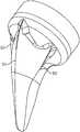
- FIG. 1shows a perspective view of the shoulder arthroplasty system in a reverse configuration.
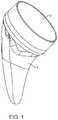
- FIG. 2shows a frontal view of the system with a cup in a reverse configuration.
- FIG. 3shows a perspective view showing of the stem with head un-installed
- FIG. 4shows a perspective view of the stem and cup.
- FIG. 5shows an anterior cross-section of the stem installed in a humerus.
- FIG. 6shows a frontal view of the stem component.
- FIG. 7shows a frontal view of the details of the proximal portion of the stem
- FIG. 8shows details of the proximal portion of the stem in bone.
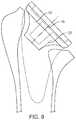
- FIG. 9shows a frontal cross-section of the stem and cup.
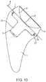
- FIG. 10shows a cross-section of the stem and cup assembled.
- FIG. 11shows a medial view of the stem component.
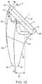
- FIG. 12shows a frontal view of the stem component
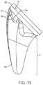
- FIG. 13shows a frontal view of the stem component and lateral fin details.
- FIG. 14Ashows a cross-section of the stem component and FIG. 14B shows a detailed cross-section of the lateral fin.
- FIG. 15Ashows a lateral view of the stem component.
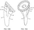
- FIG. 15Bshows a frontal view of an alternate anterior/posterior fin geometry.
- FIG. 15Cshows a perspective view of the same embodiment.
- FIG. 16Ashows a frontal view of the stem.
- FIG. 16Bshows the distal cross-section of the stem.
- FIG. 17Ashows a medial view of an alternate embodiment of the medial surface geometry.
- FIG. 18shows a lateral view of an alternate embodiment of the lateral fin.
- FIG. 19shows a perspective view of the preferred bone growth coating placement.
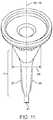
- FIG. 20Ashows a frontal view of alternate stem geometry with a cutout for additional bone graft placement.
- FIG. 20Bshows the same embodiment in a perspective view.
- FIG. 21shows a frontal view of a stemless configuration.
- FIG. 22Ashows a cross section of an alternate embodiment of the stem component with protrusions.
- FIG. 22Bshows a perspective view of the same embodiment.
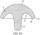
- FIG. 23shows a cross-section of the head.
- FIG. 24Ashows a frontal view of an alternative embodiment of the stem with a collar.
- FIG. 24Bshows a cross-section of the same embodiment.
- FIG. 25Ashows an auxiliary view taken normal to the proximal end of the stem of an alternative embodiment of the stem with fenestrations for implant removal.
- FIG. 25Bshows a perspective view of the same embodiment.
- FIG. 26shows an alternate bone growth coating placement.
- FIG. 27A, 27B, 27C, 27Dshows the method of determining the center of the resection plane using a disk and pin.
- FIG. 28A, 28B, 28C, 28D, 28E, 28Fshow the reaming procedure to create the proximal bone cavity.
- FIG. 29shows a cross-section of the broach in the humerus.
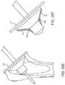
- FIG. 30Ashows a cross-section of the stemless broach in the humerus.
- FIG. 30Bshows a frontal view of the stemless broach.
- a shoulder arthroplasty systemthat is optionally convertible in use between an anatomic and a reverse shoulder implantation configuration.
- the systemincludes a short stem prosthesis that may provide several advantages.
- the reverse shoulder configurationthe system includes an articular surface cup arranged in an inlay configuration on a receptacle of the stem. This may provide for a much more compactly sized system with respect to an onlay configuration.
- the systemis configured to preferably achieve fixation in the metaphysis to preferably provide rotational and axial stability.
- the shoulder arthroplasty systemmay be implanted in both a press fit and a cemented configuration.
- the systemcan be implanted using an installation technique that preferably removes as little bone as possible thereby conserving bone in the patient. It is designed on anatomy preferably based on a statistical shape model matching that of the humerus, as described in detail below. It should be appreciated that a statistical shape model is just an example, of a non-limiting means of analysis and that other means of analysis are within the scope of this disclosure.
- FIG. 1shows a perspective view of the shoulder arthroplasty system in a reverse configuration.
- the systemincludes a stem component 1 and a polymer cup 2 in a reverse configuration.
- FIG. 2shows a frontal view of the system with the aforementioned stem component 1 that is sized and shaped to be inserted into the humerus.
- the stemhas a monoblock or monolithic configuration that is a single piece structure. The single piece stem reduces manufacturing costs and hospital inventory requirements compared to a modular stem design.
- the cup 2has an angled profile that provides a greater range of motion with less potential for notching which is loss of bone where the implant comes in contact with the glenoid, possibly during some movements.
- the stem or stemless embodimentsmay be used with, or without, or in combination with, any of the other features described in this specification (e.g. fins, fenestrations, tapers, etc.).
- the cup component 2defines a curved articulating surface near to the resection plane. This provides minimal lateralization and inferiorization for a convertible prosthesis, which leads to a more anatomical reconstruction.
- the cup component 2is interchangeable with the stem 1 .
- a collection of multiple cup components 2can be used for a single, corresponding stem component wherein each cup component of the collection has a particular articulating surface diameter and offset. This permits a user to select a cup component for use having a desired surface diameter.
- FIG. 3shows a perspective view of the shoulder arthroplasty system with a head component 3 uninstalled from the stem 1 .
- the stem component 1also includes a mechanical taper 5 that serves as a securing mechanism for the head component 3 and when secured to the stem 1 .
- the anatomic head component 3provides an articular surface 6 for anatomic shoulder reconstruction.
- FIG. 4provides perspective views of the stem component 1 .
- the stemhas an anatomic shape that is configured pursuant to a statistical shape model.
- a statistical shape modelis just an example, of a non-limiting means of analysis and that other means of analysis are within the scope of this disclosure.
- other means of analysisincluding anatomic analysis, geometric analysis, anthropometric analysis, mechanical analysis, and kinematic analysis are within the scope of this disclosure.
- the stemhas three fin like protrusions, a lateral fin 51 , anterior fin 52 , and the posterior fin 53 configured to cut into cancellous bone in the metaphysis to provide rotational stability when the system is implanted in bone.
- the finsare configured to enhance rotational stability of the stem while avoiding cortical contact in the metaphysis.
- the anterior and posterior fins 52 and 53may be used interchangeably when the stem is used in a left or right side of the patient.
- FIG. 5a cross section of the stem component inserted into the humerus is shown.
- the proximal end 7 of the stem 1is positioned along a resection plane 8 , which is the area exposed in surgery when the humeral head is surgically removed prior to preparation and implantation.
- An axis 90 normal to the resection plane 8is at an obtuse angle 91 from the long axis of the bone 9 .
- FIG. 6shows a frontal view of the stem component.
- the stemhas an overall taper shape such that the implant generally increases in size proximally which improves wedged fixation. This configuration preserves bone by providing minimal removal of bone, especially in the greater tuberosity and humeral metaphysis.
- the designallows the stem to be centered proximally within the resection plane, which thereby allows the spherical head component of the anatomic configuration to be also centered on the resection plane, recreating normal anatomy.
- the outer bone contacting surfaces of the stemare configured to optimize the proximal bone loading in the proximal metaphysis of the humerus and reduce loading distally in the diaphysis.
- the taper shapehas a proximal concave taper 10 that is generally conical and a distal taper 11 that is tapered in both the medial-lateral direction as well as the anterior-posterior direction. Additional details about the proximal and distal tapers are described elsewhere in this specification.
- the stemhas a proximal end 7 , distal end 12 , lateral side 13 and medial side 14 .
- the proximal portion of the stemhas a short cylindrical extrusion 15 perpendicular to the proximal end 7 .
- the cylindrical extrusion 15is 2.7 mm and may range from 2.5 mm to 3 mm. While this is a preferred embodiment, the stem design may have other dimensions and would work without the cylindrical section where the proximal portion of the stem is conical right up to the proximal end 7 .
- the design with the cylindrical extrusion 15is preferred because this truncates the conical taper such that the diameter of the proximal end 7 is reduced for the same taper.
- the diameter of the cylindrical extrusionranges from 30 to 40 mm although other dimensions are possible. The diameter increases with increasing patient anatomy.
- FIG. 7shows details of the concave taper 10 in the proximal portion of the stem.
- the stem geometrytransitions to a concave taper 10 .
- the proximal end 16 of the concave taper 10is congruent to the distal end of the cylindrical extrusion 15 and extends to a distal end of the taper 17 .
- the concave taper 10is defined by at least one radius 18 revolved around the axis 19 through the center of the cylindrical extrusion 15 .
- the center of the radius 20 used to create the concavityis outside the cone created by the revolution of the straight line 21 created between proximal end 16 and the distal end 17 of the concave taper 10 .
- the length of the conical section from the proximal end 7 to the distal end 17may be 18 mm but other lengths are possible. In alternate embodiments, the length of the conical section could range from 12-30 mm.
- the diameter of the proximal end of the concave taper 10is preferably equal to the cylindrical extrusion 15 described above.
- the diameter of the distal end of the taper 17 in the preferred embodimentmay be 9 mm and could range from 7 to 11 mm, although other sizes are also possible.
- FIG. 8shows the concave taper 10 and the interaction with the proximal bone during insertion of the stem 1 .
- the concave taper 10is designed to compact bone in the metaphysis during insertion. The compaction of bone is achieved when the stem is inserted into the bone. As the stem advances distally in the humerus, bone is displaced along the concave taper 10 .
- the concave taper 10is an advantageous shape because the angle formed between the axis 19 and a tangent line 22 to the concave surface increases as the stem is advanced in the bone. This provides ever-increasing compaction until final placement of the stem 1 is achieved.
- the cup component 2is uncoupled from the receptacle 4 of the stem 1 .
- the cup componentattaches primarily via a locking ring 27 , but secondarily (and especially under load) with the taper 5 .
- the proximal portion 23 of the stemhouses the receptacle for the anatomic head for anatomic shoulder replacement and the articular cup 2 for reverse shoulder replacement.
- the stemhas two receptacles; a female taper 5 and a cylindrical cavity 24 .
- the cylindrical cavity 24is concentric to the cylindrical extrusion 15 .
- the cylindrical cavity 24starts at the proximal end 7 of the stem and extends distally to flat surface 25 parallel to the proximal end 7 .
- the cylindrical cavity 24is 3.5 mm deep but it may be other depths. Between the proximal end 7 and the flat surface 25 an annular groove 26 is formed to receive the locking ring 27 of the articular cup 2 .
- a male protrusion 33has a taper that corresponds to the taper 5 in the female receptacle so that the two components engage one another.
- FIG. 9shows a cross section of the stem component 1 and articular cup 2 .
- the female taper 5is a conical tapered cavity that extends from the flat surface 25 of the cylindrical cavity 24 to a distal end 28 .
- the axis of the female taper 29is congruent with the axis of the cylindrical cavity 30 .
- this embodimentis not limited to this and the axis may be offset from the cylindrical cavity 30 but preferably remains parallel to this axis.
- the female taper 5is configured such that the diameter at the flat surface 25 is greater than the diameter at the distal end 28 .
- the total included angle 31 of the female taper in a preferred embodimentis 4.6 degrees and the length is 12 mm, although other dimensions are possible.
- the female taper 5 in the stemreceives a conical protrusion 32 in the anatomic head 3 and the conical protrusion 33 in the articular cup 2 .
- the female taper 5 and the conical protrusion 33become fixed to one another with an interference fit.
- FIG. 10shows a cross-section of the stem component 1 and articular cup 2 in an “inlay” configuration.
- the articular cup 2is affixed to the stem by the locking ring 27 in the annular groove 26 and interference fit between the conical protrusion 33 and the female taper 5 .
- the apex 122 of the concave articular surface 6is distal to the proximal end 7 that sits flush to the resection plane 8 .
- the inlay designgreatly reduces the likelihood of over-tensioning the joint. Sufficient bearing thickness is maintained to support the loads and wear from patient activity.
- FIG. 11shows a medial view of the stem without the articular cup 2 or anatomic head 3 .
- the distal taper 11has an anterior surface 36 and a posterior surface 37 .
- the distal taper 11is symmetric about a plane 38 that is congruent with the axis 19 of the cylindrical extrusion.
- the distal taper 11is generally tapered in both the medial-lateral direction and the anterior-posterior direction.
- the distal taper 11has a medial-lateral width defined by the distance from the medial surface 34 to the lateral surface 35 .
- the medial-lateral widthdecreases distally to create the medial-lateral taper.
- the distal taper 11has an anterior-posterior width defined by the distance from the anterior surface 36 to the posterior surface 37 .
- the anterior-posterior widthdecreases distally to create the anterior-posterior taper of the stem.
- the stemhas a relatively thin cross-section. In the anterior to posterior direction, the thin cross-section is best described by the distal anterior-posterior width 47 .
- the thin cross-sectionaccommodates offset of the humeral head relative to intramedullary canal. This eliminates the need for left and right specific implants and further reduces inventory requirements.
- the configurationIn the medial to lateral direction, the configuration is still thin enough to allow rotations to match resection cut without contacting cortical bone.
- the short lengthallows further flexibility in the location of the implant proximally (angular and position) as the distal stem is not constrained by cortical bone during implantation. It also preserves bone by eliminating the need to ream cortical bone.
- the anterior-posterior taper of the distal taper 11is configured to reduce loading of the cortical bone in the diaphysis and create wedge fixation.
- the anterior-posterior taperis symmetric about the medial plane 38 of the implant.
- the anterior-posterior width 47 at the distal endis less than the proximal width 48 .
- the distal end of the distal taperis rounded in both the medial-lateral and anterior-posterior directions.
- the anterior-posterior width 47 at the distal endis 3.5 mm and the medial-lateral width at the distal end is 8, although other widths are possible
- FIG. 12shows details of the medial-lateral taper geometry of the stem in a frontal view.
- the medial lateral taper geometryis configured to conform to but not contact the medial and lateral cortex of the humerus.
- the taper geometrymay provide rotational stability of the implant.
- the medial-lateral taperis curved such that the distal end 49 of the stem 1 is offset laterally a distance 39 from a point intersecting the axis of the cylindrical extrusion and the proximal end 7 . In the preferred embodiment, this lateral offset is 8.7 mm for the median size and ranges from 7-13 mm, although other distances are possible.
- the lateral surface 35 of the distal taperis defined by a convex curve 40 that extends from the proximal end to the distal end 49 .
- the curvestarts at a medial offset 41 from the most lateral edge 42 of the proximal end 7 and extends to farthest lateral edge of the distal portion 43 .
- the medial offset 41 of the lateral surface 35is the distance from the lateral edge of the cylindrical extrusion 42 to the proximal end of the lateral surface 44 .
- the offset 41provides space for a lateral fin like protrusion that is described in detail below.
- the curve of the lateral surface 35is comprised of at least one radius.
- the medial surface 36 of the distal taper 11is defined by a concave curve 45 that extends from the proximal end 7 to the distal end 49 .
- the curve 45starts at the medial most edge 46 of the proximal end 7 and extends to the farthest medial edge 92 of the distal end. It should be noted that the tapered section along the medial edge may also be interpreted as a fin-like protrusion and is described in further detail below.
- the medial curve 45is comprised of at least one radius.
- the medial-lateral taperincreases in width to the distal end of the cylindrical extrusion 15 .
- the curved medial surfaceis sized and shaped to reduce fracture risk by spreading implantation forces over a larger area during implantation.
- the total length of the implant from the center of the proximal end 7 to the distal tipranges from 44 mm to 48 mm although other lengths are possible.
- the overall length of the implant from the most distal point 49 to the farthest point superior point 50ranges from 55 mm to 61 mm although other lengths are possible.
- FIG. 13shows details of the lateral fin 51 .
- the lateral finis defined by a lateral edge 54 that follows a convex curve from the lateral most edge 42 of the cylindrical extrusion 15 to a point 55 that is tangent to the lateral surface 35 of the distal taper 11 .
- the convex curvecan be defined by at least one radius.
- the cross-section of the lateral fin protrusion 51is substantially triangular in the preferred embodiment.
- the apex 56 of the triangular cross-sectionis congruent with the lateral edge 54 previously defined.
- Alternate embodiments,may include rectangular or hemispherical like cross-sections.
- FIG. 15shows a lateral view of the stem component.
- the anterior and posterior fins 52 , 53extend from a point 57 on the distal taper 11 that is distal to the concave taper 10 and proximal to the distal end 12 of the stem.
- the anterior and posterior fins 52 , 53extend from the point 57 to meet the cylindrical extrusion 15 .
- the anterior and posterior fins 52 , 53are concave at the distal end of the fin 58 and convex at proximal end of the fin 59 .
- the concave portion of the finis tangent to the anterior/posterior surface 60 of the distal taper 11 at the distal end of the fin 58 .
- FIG. 15B and FIG. 15Cshow an alternate embodiment of the anterior and posterior fins 52 , 53 .
- the anterior and posterior finshave a medial surface 109 and a lateral surface 110 .
- the medial surface 109 and lateral surface 110are substantially parallel to each other.
- the anterior and posterior finsmay be located closer to the lateral side 13 than the medial side 14 .
- FIG. 16Bshows in the preferred embodiment, the part of the stem 1 distal to the anterior and posterior fins of the stem has an hourglass like cross-section.
- the cross-sectionis shaped such that anterior-posterior width 61 at the medial and lateral sides is greater than the center 62 of the cross-section. This preserves bone while keeping any bone contacting surfaces at the medial and lateral edges with sufficient contact area to support implant loads and avoid compromising the internal cortex.
- FIG. 17Ashows an alternate embodiment of the anterior-posterior taper geometry of the taper.
- This embodimentprovides a larger bone-contacting surface on the medial and lateral surfaces and increases the wedge fixation in the metaphysis of the bone.
- the distal taperin the alternate embodiment, has an anterior posterior width at the proximal end defined by the distance between an anterior point 63 on the cylindrical extrusion 15 and a posterior point 64 on the cylindrical extrusion 15 .
- the anterior-posterior taperis further defined by a second width defined by the distance between an anterior point 66 and a posterior point 67 .
- These 4 pointsdefine a total included angle 68 of the proximal portion of the distal taper 11 .
- a distal total included anglecan be defined by the second width, the distance between points 66 and 67 and the anterior 69 and posterior 70 points at the distal end 12 of the stem 1 .
- the total included angle 71 of the distal portion of the distal taperis less than the proximal total included angle 68 .
- FIG. 17Bshows a similar geometry but on the lateral fin 51 .
- the lateral fin 51has anterior and posterior surfaces 106 that form an angle 107 .
- the angle 107is greater than the angle formed by the distal taper angle 108
- the proximal bone contacting surfaces 72have a coating 73 for additional boney in-growth.
- Coatingsmay include plasma spray titanium, hydroxyapatite or similar coatings known in the art to enhance bone growth.
- the proximal 19-21 mm of the stemis coated.
- additional embodimentscould include coating the entire stem or any sections.
- FIG. 26shows one such embodiment of the placement of the bone growth surface where only the fins 51 , 52 , 53 of the stem are coated with a bone growth coating 73 .
- the proximal section of the stemis grit blasted and the distal portion is polished smooth.
- FIGS. 20A and 201shows an alternative embodiment of the distal portion of the stem that has a cutout 74 to contain additional bone graft.
- the medial 75 and lateral 76 edges of the cutout 74is offset from the medial 34 and lateral surfaces 35 of the stem and extends through the stem 1 in the anterior—posterior direction.
- the proximal extent of the cutout 74is distal to the concave taper 10 .
- the cutoutmay be used in any stem embodiment described herein.
- FIG. 21shows an alternate embodiment of the stem, which does not have a distal taper as described in previous embodiments.
- This configurationis commonly called a “stemless” or “canal sparing” implant.
- the deviceis surgically implanted in the same manner as the longer, “stemmed”, design, and therefore provides the surgeon with an additional option without adding complexity.
- Stemless designscan be used to further enhance positional flexibility proximally when metaphyseal fixation is adequate and cementation is not required.
- the outer bone-contacting surface of the stemhas a concave taper 10 .
- the stemless designlike the stemmed design, has a cylindrical extrusion 15 perpendicular to the proximal end 7 .
- the concave surfaceis defined by at least one radius that revolves around the axis 19 created by the cylindrical extrusion 15 .
- the stemless designalso includes at least one fin-like protrusion for rotational stability. As previously described, the fin-like protrusions extend from the distal portion of the stem to meet the proximal cylindrical section. The fins taper from the distal end 77 to a greater width at the proximal end of the fin 78 . In a preferred embodiment, fins are located at the lateral 79 , medial 80 , anterior 81 and posterior 82 aspects of the implant.
- FIG. 22Ashows a cross-sectional view of an alternate embodiment of the proximal end where the stem 1 has at least one protrusion 83 on the rim 84 of the proximal end 7 to prevent rotation of the articular cup 2 .
- a preferred arrangementis four protrusions distributed evenly along the rim 84 of the proximal end 7 .
- the protrusion 83extends from proximal end 7 of the stem.
- a rim 84is created by the outer diameter of the cylindrical extrusion 15 and the cylindrical cavity 24 .
- FIG. 23Ashows the protrusion extends radially from the inner surface 85 created by the cylindrical cavity 24 to the outer surface of the cylindrical extrusion 15 .
- FIG. 23shows a cross-sectional side view of the anatomic head component 3 which may be used with any of the stem embodiments described herein.
- the anatomic head component 3includes a long taper 32 that couples to the corresponding taper in the stem to secure the anatomic head component 3 to the stem.
- the longer than usual taperallows for a single interface for both anatomic and reverse arthroplasty.
- the long taper 32extends through the receptacle in the stem and is sized to allow the anatomic head component to be used in the same stem as an inlay articular cup (as described above) without an intermediate tray.
- the anatomic head component 3includes a curved, anatomically accurate center and radius curvature of the articular surface 86 that closely matches normal anatomy of the humeral head.
- the head component 3includes cutout 87 to reduce the weight of the component.
- the cutout 87is disposed between the outer rim of the head 88 and the central tapered protrusion 32 .
- a rounded periphery 89provides an atraumatic surface when in contact with soft tissue.
- FIG. 24Ashows a frontal view of an alternative embodiment where the stem has a collar 95 on the cylindrical portion 15 of the stem 1 .
- This embodimentis also known as a “collared” stem and is used with the smallest stem sizes to allow for placement of the head or cup, depending on whether an anatomic or a reverse is being implanted. It is allows the use of the head or cup in a stem that is too small to accommodate them as the larger stems do.
- the collar 95has a proximal surface 96 , distal surface 97 and radial surface 98 .
- the proximal surface 96 of the collar 95is congruent to the proximal end 7 of the stem.
- the distal surface 97 of the collarsits on the resection plane of the humerus.
- the radial surface 98has a diameter greater than that of the cylindrical extrusion 15 .
- the mating articular cup 2 componentshown in FIG. 24B , has an outer diameter 99 that is equal to the diameter
- FIGS. 25A and 25Bshows an alternative embodiment of the stem with fenestrations.
- the fenestrationsare used to insert instruments if the prosthesis needs to be removed. During revision, removal may be made difficult by bone that has grown onto the stem.
- the fenestrationsextend from the proximal end 7 distally. In the embodiment shown in FIG. 23 there are four fenestrations.
- the first fenestration 100is located between the lateral fin 51 and the posterior fin 53 .
- a second fenestration 101is located between the lateral fin 51 and the anterior fin 52 .
- a third fenestrationis located between the posterior fin and the medial surface 34 .
- the fourth fenestration 103is located between the anterior fin and the medial surface.
- Alternative embodimentsmay include a different number of fenestrations.
- the proximal humeral osteotomy 111is made through the anatomic neck of the humerus. Reference FIG. 27A-27D .
- the osteotomycan be made using a saw, osteotome or equivalent bone cutting instrument.
- the osteotomy 111is a planar cut made at an angle to the long axis 9 of the bone.
- the osteotomycan be sized using a set of sizing disks 112 and a guide pin 113 placed through the center of the disk 114 to establish the osteotomy center point 115 .
- the set of sizing disks 112include a matching disk for each implant size.
- the guide pin 113also acts as a temporary fixation pin to help hold the disk 112 .
- the diskis a flat cylinder used to visualize the diameter of the proximal portion of the stem relative to the resected bone surface created by the osteotomy 111 .
- At least two slots 116are cut into the sizing disk 112 to help visualize the extent of the resected bone surface and thereby preventing oversizing of the implant.
- FIG. 28A-28Fshows the next step being removal of the proximal bone.
- the proximal bone of the humerusis removed to accommodate the proximal portion of the final implant.
- the boneis removed using a proximal reamer 117 that may be attached to handle for manual reaming by hand or a power drill.
- the humerusis reamed such that the cavity 118 created by the reamer 117 is smaller than the final implant.
- FIG. 28Eshows a cross section of the reamer 117 in the humerus.
- FIG. 28Fshows the reamer over-laid with the outline of the concave taper. The area between the concave taper and the reamer is the volume of bone that will be compacted during the insertion of the stem.
- the following stepshown in FIG. 29 , shows a broach 119 that is utilized to compact the bone in the epiphysis and to create space for final implantation of the stem.
- the stemless broach 119is designed to minimize bone cutting and improve bone compaction.
- the broach 119also serves as the trial for the stem component disclosed herein.
- the broachmay also include slots to visualize the extent of the resected bone relative to broach.
- FIG. 30Ashows an alternative embodiment of the broach where a stemless broach 105 may be used to clear bone proximally.
- the stemless broach 105may be inserted over the guide pin 113 to ensure the bone cavity for the stem is located at the osteotomy center point 115 .
- the stemless broach 105shown also in FIG. 30B , may be used in both ‘stemmed’ implants and stemless implants.
- the metaphyseal boneis compacted, thus achieving additional stability.
- the stability of the implantis then confirmed. Cementing may optionally be considered if the implant is not satisfactorily stable such as in patients with extremely poor bone quality.
- the final stem componentis fitted with a humeral head or the reversed cup and the joint reduced.
Landscapes
- Health & Medical Sciences (AREA)
- Life Sciences & Earth Sciences (AREA)
- Orthopedic Medicine & Surgery (AREA)
- Animal Behavior & Ethology (AREA)
- General Health & Medical Sciences (AREA)
- Engineering & Computer Science (AREA)
- Biomedical Technology (AREA)
- Heart & Thoracic Surgery (AREA)
- Veterinary Medicine (AREA)
- Public Health (AREA)
- Surgery (AREA)
- Oral & Maxillofacial Surgery (AREA)
- Cardiology (AREA)
- Vascular Medicine (AREA)
- Transplantation (AREA)
- Nuclear Medicine, Radiotherapy & Molecular Imaging (AREA)
- Medical Informatics (AREA)
- Molecular Biology (AREA)
- Dentistry (AREA)
- Neurology (AREA)
- Prostheses (AREA)
Abstract
Description
Claims (16)
Priority Applications (5)
| Application Number | Priority Date | Filing Date | Title |
|---|---|---|---|
| US16/208,324US11033399B2 (en) | 2016-02-28 | 2018-12-03 | Shoulder arthroplasty implant system |
| US16/908,601US11833055B2 (en) | 2016-02-28 | 2020-06-22 | Shoulder arthroplasty implant system |
| US17/228,377US12220319B2 (en) | 2016-02-28 | 2021-04-12 | Shoulder arthroplasty implant system |
| US17/228,421US12150861B2 (en) | 2016-02-28 | 2021-04-12 | Shoulder arthroplasty implant system |
| US17/497,711US20220023054A1 (en) | 2016-02-28 | 2021-10-08 | Shoulder arthroplasty implant system |
Applications Claiming Priority (3)
| Application Number | Priority Date | Filing Date | Title |
|---|---|---|---|
| US201662300853P | 2016-02-28 | 2016-02-28 | |
| US15/445,658US10172714B2 (en) | 2016-02-28 | 2017-02-28 | Shoulder arthroplasty implant system |
| US16/208,324US11033399B2 (en) | 2016-02-28 | 2018-12-03 | Shoulder arthroplasty implant system |
Related Parent Applications (1)
| Application Number | Title | Priority Date | Filing Date |
|---|---|---|---|
| US15/445,658ContinuationUS10172714B2 (en) | 2016-02-28 | 2017-02-28 | Shoulder arthroplasty implant system |
Related Child Applications (3)
| Application Number | Title | Priority Date | Filing Date |
|---|---|---|---|
| US16/908,601Continuation-In-PartUS11833055B2 (en) | 2016-02-28 | 2020-06-22 | Shoulder arthroplasty implant system |
| US17/228,421ContinuationUS12150861B2 (en) | 2016-02-28 | 2021-04-12 | Shoulder arthroplasty implant system |
| US17/228,377ContinuationUS12220319B2 (en) | 2016-02-28 | 2021-04-12 | Shoulder arthroplasty implant system |
Publications (2)
| Publication Number | Publication Date |
|---|---|
| US20190105167A1 US20190105167A1 (en) | 2019-04-11 |
| US11033399B2true US11033399B2 (en) | 2021-06-15 |
Family
ID=59685745
Family Applications (4)
| Application Number | Title | Priority Date | Filing Date |
|---|---|---|---|
| US15/445,658ActiveUS10172714B2 (en) | 2016-02-28 | 2017-02-28 | Shoulder arthroplasty implant system |
| US16/208,324ActiveUS11033399B2 (en) | 2016-02-28 | 2018-12-03 | Shoulder arthroplasty implant system |
| US17/228,377Active2038-05-23US12220319B2 (en) | 2016-02-28 | 2021-04-12 | Shoulder arthroplasty implant system |
| US17/228,421Active2038-07-28US12150861B2 (en) | 2016-02-28 | 2021-04-12 | Shoulder arthroplasty implant system |
Family Applications Before (1)
| Application Number | Title | Priority Date | Filing Date |
|---|---|---|---|
| US15/445,658ActiveUS10172714B2 (en) | 2016-02-28 | 2017-02-28 | Shoulder arthroplasty implant system |
Family Applications After (2)
| Application Number | Title | Priority Date | Filing Date |
|---|---|---|---|
| US17/228,377Active2038-05-23US12220319B2 (en) | 2016-02-28 | 2021-04-12 | Shoulder arthroplasty implant system |
| US17/228,421Active2038-07-28US12150861B2 (en) | 2016-02-28 | 2021-04-12 | Shoulder arthroplasty implant system |
Country Status (6)
| Country | Link |
|---|---|
| US (4) | US10172714B2 (en) |
| EP (2) | EP3419534B1 (en) |
| JP (1) | JP6703144B2 (en) |
| AU (3) | AU2017224250B2 (en) |
| CA (1) | CA3011998A1 (en) |
| WO (1) | WO2017147618A1 (en) |
Cited By (3)
| Publication number | Priority date | Publication date | Assignee | Title |
|---|---|---|---|---|
| US11478358B2 (en) | 2019-03-12 | 2022-10-25 | Arthrosurface Incorporated | Humeral and glenoid articular surface implant systems and methods |
| US11478259B2 (en) | 2009-04-17 | 2022-10-25 | Arthrosurface, Incorporated | Glenoid resurfacing system and method |
| US12193687B2 (en) | 2009-04-17 | 2025-01-14 | Arthrosurface Incorporated | Glenoid repair system and methods of use thereof |
Families Citing this family (46)
| Publication number | Priority date | Publication date | Assignee | Title |
|---|---|---|---|---|
| US20230080207A1 (en) | 2005-02-25 | 2023-03-16 | Shoulder Innovations, Inc. | Methods and devices for less invasive glenoid replacement |
| US8778028B2 (en) | 2005-02-25 | 2014-07-15 | Shoulder Innovations, Inc. | Methods and devices for less invasive glenoid replacement |
| WO2007109340A2 (en) | 2006-03-21 | 2007-09-27 | Axiom Orthopaedics, Inc. | Femoral and humeral stem geometry and implantation method for orthopedic joint reconstruction |
| FR2932674B1 (en) | 2008-06-20 | 2011-11-18 | Tornier Sa | METHOD FOR MODELING A GLENOIDAL SURFACE OF AN OMOPLATE, DEVICE FOR IMPLANTING A GLENOIDAL COMPONENT OF A SHOULDER PROSTHESIS, AND METHOD FOR MANUFACTURING SUCH COMPOUND |
| USD685474S1 (en) | 2010-07-06 | 2013-07-02 | Tornier, Inc. | Prosthesis anchor |
| FR2978912A1 (en) | 2011-08-10 | 2013-02-15 | Tornier Inc | ANCILLARY EXTRACTION OF A PROSTHESIS |
| EP2586387A1 (en) | 2011-10-31 | 2013-05-01 | Tornier Orthopedics Ireland Ltd. | Bone reamer |
| BR112015007174A8 (en) | 2012-10-29 | 2018-04-24 | Tornier Orthopedics Ireland Ltd | Modular reverse shoulder prosthesis and respective systems |
| US10405993B2 (en) | 2013-11-13 | 2019-09-10 | Tornier Sas | Shoulder patient specific instrument |
| US10456264B2 (en) | 2014-01-24 | 2019-10-29 | Tornier, Inc. | Humeral implant anchor system |
| US12023253B2 (en) | 2014-01-24 | 2024-07-02 | Howmedica Osteonics Corp. | Humeral implant anchor system |
| FR3029769A1 (en) | 2014-12-10 | 2016-06-17 | Tornier Sa | KIT FOR A PROSTHESIS OF SHOULDER |
| EP3389513A1 (en) | 2015-12-16 | 2018-10-24 | Tornier, Inc. | Patient specific instruments and methods for joint prosthesis |
| GB201601159D0 (en)* | 2016-01-21 | 2016-03-09 | Univ Hospitals Coventry & Warwickshire Nhs Trust | Prosthesis |
| US11833055B2 (en) | 2016-02-28 | 2023-12-05 | Integrated Shoulder Collaboration, Inc. | Shoulder arthroplasty implant system |
| JP6703144B2 (en) | 2016-02-28 | 2020-06-03 | コンソーシアム オブ フォーカスド オーソペディスツ, エルエルシー | Shoulder arthroplasty implant system |
| US10463499B2 (en) | 2016-03-25 | 2019-11-05 | Tornier, Inc. | Stemless shoulder implant with fixation components |
| EP3445292B1 (en) | 2016-04-19 | 2022-12-21 | Imascap SAS | Pre-operatively planned humeral implant and planning method |
| EP3260087B1 (en) | 2016-06-24 | 2019-08-07 | Tornier | Set for a glenoid implant |
| US11129724B2 (en) | 2016-07-28 | 2021-09-28 | Howmedica Osteonics Corp. | Stemless prosthesis anchor component |
| US10898348B2 (en)* | 2016-12-13 | 2021-01-26 | Tornier | Surgical shoulder articulation replacement method |
| EP4520302A3 (en) | 2017-04-14 | 2025-04-16 | Shoulder Innovations, Inc. | Total shoulder prosthesis having inset glenoid implant convertible from anatomic to reverse |
| US10959742B2 (en) | 2017-07-11 | 2021-03-30 | Tornier, Inc. | Patient specific humeral cutting guides |
| EP3651664A1 (en) | 2017-07-11 | 2020-05-20 | Tornier, Inc. | Guides and instruments for improving accuracy of glenoid implant placement |
| MX2020003194A (en) | 2017-09-25 | 2020-12-09 | Howmedica Osteonics Corp | Patient specific stemless prosthesis anchor components. |
| US11399948B2 (en) | 2017-12-11 | 2022-08-02 | Howmedica Osteonics Corp. | Stemless prosthesis anchor components and kits |
| CA3087066A1 (en)* | 2017-12-29 | 2019-07-04 | Tornier, Inc. | Patient specific humeral implant components |
| EP3520738B1 (en) | 2018-01-31 | 2021-01-06 | Tornier | Prosthesis for a fractured long bone |
| US12138172B2 (en) | 2018-04-30 | 2024-11-12 | Shoulder Innovations, Inc. | Inset/onlay glenoid, porous coated convertible glenoid, and humeral heads with textured undersides |
| EP3833301A4 (en)* | 2018-07-27 | 2022-05-11 | Ignite Orthopedics LLC | IMPLANTS, SYSTEMS AND METHODS OF USE THEREOF |
| CN112955083A (en)* | 2018-09-16 | 2021-06-11 | Ignite骨科有限责任公司 | Bone reamer and method of use thereof |
| WO2020072466A1 (en)* | 2018-10-02 | 2020-04-09 | Tornier, Inc. | Metaphyseal referencing technique and instrument |
| EP4257090A3 (en) | 2018-10-02 | 2023-12-13 | Howmedica Osteonics Corp. | Shoulder prosthesis components and assemblies |
| AU2020237088B2 (en) | 2019-03-11 | 2025-09-04 | Shoulder Innovations, Inc. | Total reverse shoulder systems and methods |
| US11801151B2 (en) | 2019-03-12 | 2023-10-31 | Howmedica Osteonics Corp. | Anatomic shell 2-in-1 window trial |
| US11571310B2 (en) | 2019-04-03 | 2023-02-07 | Catalyst Orthoscience Inc. | Stemmed implant |
| US11458019B2 (en) | 2019-06-25 | 2022-10-04 | Depuy Ireland Unlimited Company | Prosthetic implants including a frame for fixation to bone and related methods |
| EP4527357A3 (en)* | 2019-10-01 | 2025-06-04 | Howmedica Osteonics Corporation | Shoulder prosthesis components and assemblies |
| USD951449S1 (en) | 2019-10-01 | 2022-05-10 | Howmedica Osteonics Corp. | Humeral implant |
| USD938590S1 (en)* | 2019-10-01 | 2021-12-14 | Howmedica Osteonics Corp. | Humeral implant |
| CN114502107B (en)* | 2019-10-01 | 2025-08-29 | 赫迈迪卡奥斯特尼克斯公司 | Reverse shoulder system |
| US20230038980A1 (en)* | 2020-03-25 | 2023-02-09 | Howmedica Osteonics Corp. | Metaphyseal referencing technique and instrument |
| USD938034S1 (en) | 2020-03-31 | 2021-12-07 | Howmedica Osteonics Corp. | Humeral implant |
| AU2021202801A1 (en) | 2020-05-07 | 2021-11-25 | Howmedica Osteonics Corp. | Stemless metaphyseal humeral implant |
| KR102713935B1 (en)* | 2022-05-10 | 2024-10-11 | 주식회사 코렌텍 | Humeral Stem with Enhanced Rotational Stability |
| AU2023401884A1 (en)* | 2022-11-28 | 2025-06-12 | Biomet Manufacturing, Llc | Superior approach stemless implant |
Citations (159)
| Publication number | Priority date | Publication date | Assignee | Title |
|---|---|---|---|---|
| US4986833A (en) | 1989-05-05 | 1991-01-22 | Worland Richard L | Glenoid component for an artificial shoulder joint |
| US5032132A (en) | 1990-01-22 | 1991-07-16 | Boehringer Mannheim Corporation | Glenoid component |
| US5658348A (en) | 1996-09-09 | 1997-08-19 | Bristol-Myers Squibb Company | Acetabular implant with threaded liner and locking ring |
| FR2737107B1 (en) | 1995-07-26 | 1997-09-05 | Medinov Sa | ASSEMBLY DEVICE BETWEEN TWO PARTS OF A PROSTHETIC ELEMENT IN PARTICULAR |
| FR2652498B1 (en) | 1989-10-04 | 1997-12-26 | Medinov | MODULAR ASSEMBLY FOR SHOULDER PROSTHESIS. |
| US5728161A (en) | 1995-06-08 | 1998-03-17 | Depuy Orthopedics, Inc. | Large taper modular shoulder prosthesis |
| US6283999B1 (en) | 1999-01-29 | 2001-09-04 | Depuy Orthopaedics, Inc. | Shoulder prothesis with humeral fracture stem |
| WO2001067988A2 (en) | 2000-03-16 | 2001-09-20 | Eugene M. Wolf M.D. Inc | Total shoulder arthroplasty apparatus |
| WO2002017822A1 (en) | 2000-09-01 | 2002-03-07 | Wolf Eugene M | Facile total shoulder arthroplasty apparatus and method |
| US6364910B1 (en) | 2001-07-11 | 2002-04-02 | Biomet, Inc. | Method and apparatus for use of a glenoid component |
| US6368353B1 (en)* | 1999-02-24 | 2002-04-09 | Michel A. Arcand | Shoulder prosthesis apparatus and methods |
| US6406495B1 (en) | 1998-12-22 | 2002-06-18 | Sulzer Orthopedics Ltd. | Glenoid prosthesis and a modular system with glenoid prostheses |
| US20020177900A1 (en) | 2000-12-14 | 2002-11-28 | Serbousek Jon C. | Prosthesis with feature aligned to trabeculae |
| US20030171821A1 (en) | 2000-07-29 | 2003-09-11 | Klaus Draenert | Neck-preserving-stem NPS |
| US6673115B2 (en) | 1997-09-09 | 2004-01-06 | Stryker Technologies Corporation | Anatomic glenoid shoulder prosthesis together with methods and tools for implanting same |
| US6699289B2 (en) | 2001-12-31 | 2004-03-02 | Depuy Orthopaedics, Inc. | Augmented glenoid component having an interrupted surface and associated method for securing the augmented glenoid component to a glenoid surface of a scapula |
| US6733502B2 (en) | 2002-05-15 | 2004-05-11 | Cross Medical Products, Inc. | Variable locking spinal screw having a knurled collar |
| US6761740B2 (en) | 2002-02-15 | 2004-07-13 | Tornier | Glenoid component of a shoulder prosthesis and complete shoulder prosthesis incorporating such a component |
| US6790234B1 (en) | 2002-01-04 | 2004-09-14 | Frankle Mark A | Reverse shoulder prosthesis system |
| FR2848099B1 (en) | 2002-12-10 | 2005-02-11 | Tornier Sa | GAME OF PROTHETIC COMPONENTS AND PROSTHESIS OF SHOULDER COMPOSED FROM SUCH A GAME |
| US6887277B2 (en) | 2001-11-21 | 2005-05-03 | Centerpulse Orthopedics Ltd. | Shoulder joint prosthesis |
| US6899736B1 (en) | 2002-08-21 | 2005-05-31 | Centerpulse Orthopedics, Ltd. | Shoulder joint prosthesis |
| US6911047B2 (en) | 2000-03-17 | 2005-06-28 | Depuy Orthopaedics, Inc. | Apparatus and method for securing a cementless glenoid component to a glenoid surface of a scapula |
| US6942699B2 (en) | 2001-07-11 | 2005-09-13 | Biomet, Inc. | Shoulder prosthesis |
| US6953478B2 (en) | 1999-12-23 | 2005-10-11 | Depuy France | Shoulder prosthesis assembly |
| US6955677B2 (en) | 2002-10-15 | 2005-10-18 | The University Of North Carolina At Chapel Hill | Multi-angular fastening apparatus and method for surgical bone screw/plate systems |
| US6969406B2 (en) | 2002-02-04 | 2005-11-29 | Tornier Sa | Prosthetic element comprising two components and process for assembling such a prosthetic element |
| US7001389B1 (en) | 2002-07-05 | 2006-02-21 | Navarro Richard R | Fixed and variable locking fixation assembly |
| US7011686B2 (en) | 2002-09-30 | 2006-03-14 | Depuy Products, Inc. | Reverse-type humeral prosthesis |
| US20060069445A1 (en) | 2004-09-27 | 2006-03-30 | Ondrla Jeffrey M | Extended articulation prosthesis adaptor and associated method |
| US7169184B2 (en) | 2003-04-30 | 2007-01-30 | Lima Lto Spa | Inverse prosthesis for the articulation of the shoulder |
| US7175663B1 (en) | 2003-10-08 | 2007-02-13 | Biomet Manufacturing Corp. | Shoulder implant assembly |
| US7204854B2 (en) | 2002-08-15 | 2007-04-17 | Arthrex, Inc. | Metal back prosthetic glenoid component with cemented pegs and hollow metal cage screw |
| US7241314B1 (en) | 2004-09-16 | 2007-07-10 | Biomet Manufacturing Corp. | Reverse shoulder prosthesis |
| US20070219638A1 (en) | 2005-10-24 | 2007-09-20 | Benoist Girard Sas | Prosthetic glenoid component |
| US7309360B2 (en) | 2004-06-15 | 2007-12-18 | Tornier | Set of humeral components for total shoulder prosthesis |
| US7329284B2 (en) | 2002-09-27 | 2008-02-12 | Depuy Products, Inc. | Concave resurfacing prosthesis |
| US7338528B2 (en) | 2003-02-04 | 2008-03-04 | Biomet Manufacturing Corp. | Humeral stem with anatomical location of taper access for fixation of humeral head |
| US20080234833A1 (en) | 2004-03-23 | 2008-09-25 | B.I. Tec Ltd | Method of Designing and Manufacturing Artificial Joint Stem with Use of Composite Material |
| US7445638B2 (en) | 2005-03-03 | 2008-11-04 | Biomet France | Humeral implant for shoulder prosthesis |
| US7462197B2 (en) | 2004-06-15 | 2008-12-09 | Tornier Sas | Glenoidal component of a shoulder prosthesis, set of elements constituting such a component and total shoulder prosthesis incorporating such a component |
| US7476253B1 (en) | 2004-08-11 | 2009-01-13 | Biomet Manufacturing Corporation | Humeral head preserving implant |
| US7556652B2 (en) | 2004-02-05 | 2009-07-07 | Exactech, Inc. | Shoulder prosthesis with humeral fracture stem |
| US20090248087A1 (en) | 2008-03-03 | 2009-10-01 | Orthohelix Surgical Designs, Inc. | Variable axis locking mechanism for use in orthopedic implants |
| US7604665B2 (en) | 2006-09-20 | 2009-10-20 | Depuy Products, Inc. | Glenoid component for shoulder arthroplasty |
| US7637928B2 (en) | 2004-01-26 | 2009-12-29 | Synthes Usa, Llc | Variable angle locked bone fixation system |
| US7753959B2 (en) | 2006-03-20 | 2010-07-13 | Biomet Manufacturing Corp. | Modular center pegged glenoid |
| US20100312286A1 (en) | 2007-10-30 | 2010-12-09 | Dell Oca Alberto A Fernandez | Variable Angle Locked Bone Plate |
| US7854768B2 (en)* | 2006-01-20 | 2010-12-21 | Zimmer Technology, Inc. | Shoulder arthroplasty system |
| US20110029089A1 (en) | 2006-08-03 | 2011-02-03 | Plustek S.R.L. | Shoulder Prosthesis |
| US7892287B2 (en) | 2004-09-27 | 2011-02-22 | Depuy Products, Inc. | Glenoid augment and associated method |
| US20110060417A1 (en) | 2008-02-21 | 2011-03-10 | Smith & Nephew Orthopaedics Ag | Shoulder joint prosthesis, especially reverse shoulder joint prosthesis |
| EP1598034B1 (en) | 2004-05-19 | 2011-03-30 | Zimmer GmbH | Glenoidal anchorage |
| US7918895B2 (en) | 2007-03-07 | 2011-04-05 | Biomet Manufacturing Corp. | Method and apparatus for removing a bearing |
| US7922769B2 (en) | 2004-09-27 | 2011-04-12 | Depuy Products, Inc. | Modular glenoid prosthesis and associated method |
| US20110118795A1 (en) | 2009-11-17 | 2011-05-19 | Adam Hashmi | Variable Angle Locking Buttress Pins |
| US7947135B2 (en)* | 2007-03-26 | 2011-05-24 | Mx Orthopedics Corp. | Proximally self-locking long bone prosthesis |
| US20110202092A1 (en) | 2008-06-03 | 2011-08-18 | Synthes Usa, Llc | Variable Angle Fixation Element System |
| US8048161B2 (en) | 2007-11-07 | 2011-11-01 | Arthex, Inc. | Hybrid glenoid for shoulder arthroplasty |
| US8062376B2 (en) | 2002-07-10 | 2011-11-22 | Biomet Manufacturing Corp. | Shoulder implant assembly |
| US8062294B2 (en) | 2005-09-15 | 2011-11-22 | Spineform Llc | Implant with integral fastener retention |
| US8070820B2 (en) | 2003-10-08 | 2011-12-06 | Biomet Manufacturing Corp. | Shoulder implant assembly |
| US8080063B2 (en) | 2006-04-13 | 2011-12-20 | Tornier Sas | Glenoid component with an anatomically optimized keel |
| US8092466B2 (en) | 2007-10-12 | 2012-01-10 | Howmedica Osteonics Corp. | Expandable reverse shoulder trial |
| US8123815B2 (en) | 2008-11-24 | 2012-02-28 | Biomet Manufacturing Corp. | Multiple bearing acetabular prosthesis |
| US8231683B2 (en) | 2009-12-08 | 2012-07-31 | Depuy Products, Inc. | Shoulder prosthesis assembly having glenoid rim replacement structure |
| US8241366B2 (en) | 2009-03-11 | 2012-08-14 | Exactech Inc. | Motion inducing reverse shoulder assembly |
| US20120209392A1 (en) | 2011-02-07 | 2012-08-16 | Exactech, Inc. | Adjustable reverse shoulder prostheses |
| US8246687B2 (en) | 2009-11-18 | 2012-08-21 | Biomet Manufacturing Corp. | Shoulder prosthetic |
| US8323347B2 (en) | 2005-08-25 | 2012-12-04 | Arthrex, Inc. | Shoulder prosthesis |
| US20120323284A1 (en) | 2011-06-15 | 2012-12-20 | Smith & Nephew, Inc. | Variable angle locking implant |
| US8382807B2 (en) | 2005-07-25 | 2013-02-26 | Smith & Nephew, Inc. | Systems and methods for using polyaxial plates |
| US8425614B2 (en) | 2006-03-20 | 2013-04-23 | Biomet Manufacturing Corp. | Modular center pegged glenoid |
| EP2586387A1 (en) | 2011-10-31 | 2013-05-01 | Tornier Orthopedics Ireland Ltd. | Bone reamer |
| US8444698B2 (en) | 2004-12-29 | 2013-05-21 | Depuy Products, Inc. | Joint prosthesis with infinitely positionable head |
| US8454702B2 (en) | 2011-01-20 | 2013-06-04 | Biomet Manufacturing Corp. | Reverse shoulder prosthetic |
| US8465548B2 (en) | 2010-11-24 | 2013-06-18 | DePuy Synthes Products, LLC | Modular glenoid prosthesis |
| US8480750B2 (en) | 2010-11-24 | 2013-07-09 | DePuy Synthes Products, LLC | Modular glenoid prosthesis |
| US8486116B2 (en) | 2010-01-08 | 2013-07-16 | Biomet Manufacturing Ring Corporation | Variable angle locking screw |
| US8500784B2 (en) | 2009-05-26 | 2013-08-06 | DePuy Synthes Products, LLC | Variable angle screw plate systems |
| US8512410B2 (en) | 2011-01-11 | 2013-08-20 | Arthex, Inc. | Stemless shoulder implant |
| US8574268B2 (en) | 2004-01-26 | 2013-11-05 | DePuy Synthes Product, LLC | Highly-versatile variable-angle bone plate system |
| US8690951B2 (en) | 2005-11-18 | 2014-04-08 | Zimmer, Gmbh | Base platform for an artificial joint |
| US8690952B2 (en) | 2006-05-22 | 2014-04-08 | Mathys Ag Bettlach | Shoulder prosthesis |
| US8721727B2 (en) | 2009-11-24 | 2014-05-13 | Tornier Sas | Glenoid component with offset center and associated methods |
| US8721728B2 (en) | 2011-04-27 | 2014-05-13 | Biomet Manufacturing, Llc | Modular glenoid prosthesis |
| US8721726B2 (en) | 2008-12-29 | 2014-05-13 | Aston Medical Developments Limited | Glenoid implant |
| US8728129B2 (en) | 2011-01-07 | 2014-05-20 | Biomet Manufacturing, Llc | Variable angled locking screw |
| US8764836B2 (en) | 2011-03-18 | 2014-07-01 | Lieven de Wilde | Circular glenoid method for shoulder arthroplasty |
| US8795379B2 (en) | 2001-07-11 | 2014-08-05 | Biomet Manufacturing, Llc | Variable prosthesis |
| US20140277181A1 (en) | 2013-03-14 | 2014-09-18 | Arthrex, Inc. | Variable angle locking screw and plate |
| US8840671B2 (en) | 2011-03-25 | 2014-09-23 | Zimmer Gmbh | Shoulder prosthesis |
| US8864834B2 (en) | 2007-01-30 | 2014-10-21 | Tornier Sas | Method and apparatus for fitting a shoulder prosthesis |
| US8870962B2 (en) | 2006-03-23 | 2014-10-28 | Exactech, Inc. | Reverse shoulder prosthesis |
| US8876907B2 (en) | 2012-07-26 | 2014-11-04 | Howmedica Osteonics Corp. | Cement pressurizing glenoid |
| US8882845B2 (en) | 2010-05-05 | 2014-11-11 | DePuy Synthes Products, LLC | Mobile bearing glenoid prosthesis |
| US20140379089A1 (en) | 2013-06-19 | 2014-12-25 | Arthrex, Inc. | Stemless shoulder implant |
| US8968410B2 (en) | 2010-02-10 | 2015-03-03 | Limacorporate Spa | Glenoid support for shoulder prosthesis |
| US8974536B2 (en) | 2007-01-30 | 2015-03-10 | Tornier Sas | Intra-articular joint replacement |
| US20150134066A1 (en) | 2013-11-14 | 2015-05-14 | Arthrex, Inc. | Shoulder implant with stem |
| US9039745B2 (en) | 2012-04-26 | 2015-05-26 | Biomet Manufacturing, Llc | One-piece variable angle locking washer |
| US9044330B2 (en) | 2013-03-12 | 2015-06-02 | DePuy Synthes Products, Inc. | System and method for implanting a secondary glenoid prosthesis |
| US9066806B2 (en) | 2012-04-23 | 2015-06-30 | Zimmer, Inc. | Glenoid implant |
| US9072554B2 (en) | 2005-09-21 | 2015-07-07 | Children's Hospital Medical Center | Orthopedic implant |
| US9084680B2 (en) | 2011-10-05 | 2015-07-21 | Biomet Manufacturing, Llc | Multiple bearing humeral prosthesis |
| EP2083759B1 (en) | 2006-10-23 | 2015-09-02 | Innovative Design Orthopaedics Limited | Shoulder prosthesis |
| US20150250601A1 (en) | 2013-12-30 | 2015-09-10 | Shoulder Options, Inc. | Instruments and techniques for orienting prosthesis components for joint prostheses |
| US20150265411A1 (en) | 2012-10-29 | 2015-09-24 | Tornier Orthopedics Ireland Ltd. | Systems for reverse shoulder implants |
| US9161843B2 (en) | 2012-03-30 | 2015-10-20 | DePuy Synthes Products, Inc. | Surgical method for implanting a stemless humeral component to the humerus of a patient |
| US20150359575A1 (en) | 2013-01-15 | 2015-12-17 | Zimmer Gmbh | Surgical bone screw and implant system |
| US9226830B2 (en) | 2011-03-18 | 2016-01-05 | DePuy Synthes Products, Inc. | Device and method for retroversion correction for shoulder arthroplasty |
| US9259255B2 (en) | 2009-07-15 | 2016-02-16 | Orthohelix Surgical Designs, Inc. | Variable axis locking mechanism for use in orthopedic implants |
| US9351844B2 (en) | 2010-10-22 | 2016-05-31 | Tornier, Inc. | Set of glenoid components for a shoulder prosthesis |
| WO2016094739A1 (en) | 2014-12-10 | 2016-06-16 | Tornier Sas | Convertible stem / fracture stem |
| US9387022B2 (en) | 2012-06-27 | 2016-07-12 | DePuy Synthes Products, Inc. | Variable angle bone fixation device |
| US9402730B2 (en) | 2013-02-15 | 2016-08-02 | Arthrex, Inc. | Fenestrated humeral prosthesis and methods of shoulder arthroplasty |
| EP2689750B1 (en) | 2012-07-23 | 2016-08-24 | Tornier Orthopedics Ireland Ltd. | Glenoidal implant for shoulder prosthesis and surgical kit |
| US9433508B2 (en) | 2012-09-21 | 2016-09-06 | Zimmer, Inc. | Shoulder implant system |
| US9433507B2 (en) | 2006-03-21 | 2016-09-06 | Tornier, Inc. | Non-spherical articulating surfaces in shoulder and hip replacement |
| US20160270922A1 (en) | 2015-03-19 | 2016-09-22 | Limacorporate S.P.A. | Glenoid Anchor for a Shoulder Joint Prosthesis |
| US9474619B2 (en) | 2006-03-21 | 2016-10-25 | Tornier, Inc. | Glenoid component with improved fixation stability |
| US9480570B2 (en) | 2013-03-13 | 2016-11-01 | Biomet Manufacturing, Llc | Porous metal glenoid and associated method for molding the same |
| US9498345B2 (en) | 2011-02-01 | 2016-11-22 | Tornier Sas | Glenoid implant for a shoulder prosthesis, and surgical kit |
| US9498334B2 (en) | 2012-03-27 | 2016-11-22 | DePuy Synthes Products, Inc. | Glenoid defect-filling component |
| US9522067B2 (en) | 2011-02-13 | 2016-12-20 | Missy, Llc | Shoulder arthroplasty systems and configurations for components thereof |
| US9526549B2 (en) | 2012-01-16 | 2016-12-27 | Carbofix Orthopedics Ltd. | Bone screw with insert |
| US20160374815A1 (en) | 2013-07-04 | 2016-12-29 | Medacta International Sa | Prosthesis for anatomical or reverse reconstruction of the shoulder joint |
| US9545311B2 (en) | 2009-03-05 | 2017-01-17 | Tornier, Inc. | Glenoid implant anchor post |
| US9549820B2 (en) | 2009-06-25 | 2017-01-24 | Zimmer, Inc. | Glenoid implant with synthetic labrum |
| US9554837B2 (en) | 2007-05-03 | 2017-01-31 | Medartis Ag | Device for fixing an elongate element in a retaining structure |
| US9597203B2 (en) | 2015-03-25 | 2017-03-21 | Tornier, Inc. | Modular humeral implant |
| US9610165B2 (en) | 2005-10-01 | 2017-04-04 | Cecile Nerot | Humeral component of a shoulder joint prosthesis |
| US9622869B2 (en) | 2004-10-25 | 2017-04-18 | Cecile Nerot | Modular humeral prosthesis for an inverted shoulder prosthesis |
| US9642710B2 (en) | 2012-02-07 | 2017-05-09 | Biomet Manufacturing, Llc | Humeral implant having a floating bearing |
| US9687282B2 (en) | 2006-03-07 | 2017-06-27 | Orthohelix Surgical Designs, Inc. | Orthopedic plate having threaded holes for locking screws or pegs and non-threaded holes for a variable axis locking mechanism |
| US9713533B2 (en) | 2014-12-02 | 2017-07-25 | Biomet Manufacturing, Llc | In-line pegged hybrid glenoid |
| WO2017147618A1 (en) | 2016-02-28 | 2017-08-31 | Consortium Of Focused Orthopedists, Llc | Shoulder arthroplasty implant system |
| US9788874B2 (en) | 2012-05-03 | 2017-10-17 | Aristotech Industries Gmbh | Bone plate system for osteosynthesis |
| WO2017184792A1 (en) | 2016-04-19 | 2017-10-26 | Imascap Sas | Pre-operatively planned humeral implant and planning method |
| US20170319248A1 (en) | 2016-05-06 | 2017-11-09 | Cardinal Health 247, Inc. | Variable-angle locking screws, and bone plate systems that include variable-angle locking screws |
| US9814471B2 (en) | 2013-03-11 | 2017-11-14 | Catalyst Orthoscience Inc. | Glenoid arthroplasty and offset reamers |
| US9814588B2 (en) | 2015-08-10 | 2017-11-14 | Catalyst Orthoscience Inc. | Glenoid arthroplasty with multi-directional fixation |
| US9833327B2 (en) | 2009-03-20 | 2017-12-05 | DePuy Synthes Products, Inc. | Glenoid component for use in shoulder arthroplasty |
| US20170367836A1 (en) | 2016-06-24 | 2017-12-28 | Tornier | Set for a glenoid implant |
| US20180064537A1 (en) | 2015-03-19 | 2018-03-08 | Limacorporate S.P.A. | Improved glenoid anchor for a shoulder joint prosthesis |
| US20180092747A1 (en) | 2015-04-07 | 2018-04-05 | Zimmer, Inc. | Convertible glenoid |
| US20180104065A1 (en) | 2015-03-26 | 2018-04-19 | Imperial Innovations Limited | Prosthetic glenoid component |
| US20180193074A1 (en) | 2017-01-09 | 2018-07-12 | Zimmer, Inc. | Poly-axial fixation posts |
| US20180193150A1 (en) | 2017-01-09 | 2018-07-12 | Nathan A. Winslow | Adjustable orthopedic connections |
| US20180200067A1 (en) | 2017-01-19 | 2018-07-19 | Encore Medical, L.P. (D/B/A Djo Surgical) | Shoulder Implant Components |
| US10028838B2 (en) | 2014-06-30 | 2018-07-24 | Tornier, Inc. | Augmented glenoid components and devices for implanting the same |
| US20180303619A1 (en) | 2017-04-25 | 2018-10-25 | Biomet Manufacturing, Llc | Augmented glenoid with groove |
| US20180318096A1 (en) | 2013-11-04 | 2018-11-08 | Craig Boulris | Shoulder Replacement With Enhanced Glenoid Fixation |
| US20190076261A1 (en) | 2009-12-14 | 2019-03-14 | Tornier Sas | Shoulder prosthesis glenoid component |
| US10335285B2 (en) | 2016-10-13 | 2019-07-02 | Howmedica Osteonics Corp. | Reviseable stemless prostheses and methods |
| US10456264B2 (en) | 2014-01-24 | 2019-10-29 | Tornier, Inc. | Humeral implant anchor system |
| US10463499B2 (en) | 2016-03-25 | 2019-11-05 | Tornier, Inc. | Stemless shoulder implant with fixation components |
| US10702390B2 (en) | 2012-06-28 | 2020-07-07 | DePuy Synthes Products, Inc. | Modified glenoid components and methods of installing same |
| US10722373B2 (en) | 2018-07-27 | 2020-07-28 | Ignite Orthopedics Llc | Implants, systems and methods of using the same |
Family Cites Families (3)
| Publication number | Priority date | Publication date | Assignee | Title |
|---|---|---|---|---|
| US9381086B2 (en)* | 2010-11-30 | 2016-07-05 | Shoulder Innovations, Llc | Stem for use in joint arthroplasty |
| US8945234B2 (en) | 2012-04-26 | 2015-02-03 | Optimus Orthopedic Designs LLC | Prosthesis having a metaphyseal element |
| GB2534141A (en)* | 2015-01-13 | 2016-07-20 | Imp Innovations Ltd | Hip stem |
- 2017
- 2017-02-28JPJP2018563771Apatent/JP6703144B2/enactiveActive
- 2017-02-28WOPCT/US2017/020027patent/WO2017147618A1/ennot_activeCeased
- 2017-02-28AUAU2017224250Apatent/AU2017224250B2/enactiveActive
- 2017-02-28USUS15/445,658patent/US10172714B2/enactiveActive
- 2017-02-28EPEP17757446.4Apatent/EP3419534B1/enactiveActive
- 2017-02-28CACA3011998Apatent/CA3011998A1/ennot_activeAbandoned
- 2017-02-28EPEP22201861.6Apatent/EP4140423A1/enactivePending
- 2018
- 2018-12-03USUS16/208,324patent/US11033399B2/enactiveActive
- 2021
- 2021-04-12USUS17/228,377patent/US12220319B2/enactiveActive
- 2021-04-12USUS17/228,421patent/US12150861B2/enactiveActive
- 2022
- 2022-04-11AUAU2022202390Apatent/AU2022202390B2/enactiveActive
- 2024
- 2024-05-16AUAU2024203246Apatent/AU2024203246A1/enactivePending
Patent Citations (230)
| Publication number | Priority date | Publication date | Assignee | Title |
|---|---|---|---|---|
| US4986833A (en) | 1989-05-05 | 1991-01-22 | Worland Richard L | Glenoid component for an artificial shoulder joint |
| FR2652498B1 (en) | 1989-10-04 | 1997-12-26 | Medinov | MODULAR ASSEMBLY FOR SHOULDER PROSTHESIS. |
| US5032132A (en) | 1990-01-22 | 1991-07-16 | Boehringer Mannheim Corporation | Glenoid component |
| US5728161A (en) | 1995-06-08 | 1998-03-17 | Depuy Orthopedics, Inc. | Large taper modular shoulder prosthesis |
| FR2737107B1 (en) | 1995-07-26 | 1997-09-05 | Medinov Sa | ASSEMBLY DEVICE BETWEEN TWO PARTS OF A PROSTHETIC ELEMENT IN PARTICULAR |
| US5658348A (en) | 1996-09-09 | 1997-08-19 | Bristol-Myers Squibb Company | Acetabular implant with threaded liner and locking ring |
| US6673115B2 (en) | 1997-09-09 | 2004-01-06 | Stryker Technologies Corporation | Anatomic glenoid shoulder prosthesis together with methods and tools for implanting same |
| US6406495B1 (en) | 1998-12-22 | 2002-06-18 | Sulzer Orthopedics Ltd. | Glenoid prosthesis and a modular system with glenoid prostheses |
| US6283999B1 (en) | 1999-01-29 | 2001-09-04 | Depuy Orthopaedics, Inc. | Shoulder prothesis with humeral fracture stem |
| US6558425B2 (en) | 1999-01-29 | 2003-05-06 | Depuy Orthopaedics, Inc. | Shoulder prosthesis with humeral fracture stem |
| US6368353B1 (en)* | 1999-02-24 | 2002-04-09 | Michel A. Arcand | Shoulder prosthesis apparatus and methods |
| US7611539B2 (en) | 1999-12-23 | 2009-11-03 | Depuy France | Shoulder prosthesis assembly |
| US6953478B2 (en) | 1999-12-23 | 2005-10-11 | Depuy France | Shoulder prosthesis assembly |
| WO2001067988A2 (en) | 2000-03-16 | 2001-09-20 | Eugene M. Wolf M.D. Inc | Total shoulder arthroplasty apparatus |
| US6911047B2 (en) | 2000-03-17 | 2005-06-28 | Depuy Orthopaedics, Inc. | Apparatus and method for securing a cementless glenoid component to a glenoid surface of a scapula |
| US7160328B2 (en) | 2000-03-17 | 2007-01-09 | Deputy Products, Inc. | Method for securing a glenoid component to a scapula |
| US20030171821A1 (en) | 2000-07-29 | 2003-09-11 | Klaus Draenert | Neck-preserving-stem NPS |
| WO2002017822A1 (en) | 2000-09-01 | 2002-03-07 | Wolf Eugene M | Facile total shoulder arthroplasty apparatus and method |
| US20020177900A1 (en) | 2000-12-14 | 2002-11-28 | Serbousek Jon C. | Prosthesis with feature aligned to trabeculae |
| US6652591B2 (en) | 2000-12-14 | 2003-11-25 | Depuy Orthopaedics, Inc. | Prosthesis with feature aligned to trabeculae |
| US8795379B2 (en) | 2001-07-11 | 2014-08-05 | Biomet Manufacturing, Llc | Variable prosthesis |
| US8906103B2 (en) | 2001-07-11 | 2014-12-09 | Biomet Manufacturing, Llc | Shoulder prosthesis |
| US9700423B2 (en) | 2001-07-11 | 2017-07-11 | Biomet Manufacturing, Llc | Shoulder prosthesis |
| US6364910B1 (en) | 2001-07-11 | 2002-04-02 | Biomet, Inc. | Method and apparatus for use of a glenoid component |
| US6942699B2 (en) | 2001-07-11 | 2005-09-13 | Biomet, Inc. | Shoulder prosthesis |
| US7819923B2 (en) | 2001-07-11 | 2010-10-26 | Biomet Manufacturing Corp. | Shoulder prosthesis |
| US10603181B2 (en) | 2001-07-11 | 2020-03-31 | Biomet Manufacturing, Llc | Shoulder prosthesis |
| US8236059B2 (en) | 2001-07-11 | 2012-08-07 | Biomet Manufacturing, Inc. | Shoulder prothesis |
| US9241803B2 (en) | 2001-07-11 | 2016-01-26 | Biomet Manufacturing, Llc. | Shoulder prosthesis |
| US6887277B2 (en) | 2001-11-21 | 2005-05-03 | Centerpulse Orthopedics Ltd. | Shoulder joint prosthesis |
| US6699289B2 (en) | 2001-12-31 | 2004-03-02 | Depuy Orthopaedics, Inc. | Augmented glenoid component having an interrupted surface and associated method for securing the augmented glenoid component to a glenoid surface of a scapula |
| US6790234B1 (en) | 2002-01-04 | 2004-09-14 | Frankle Mark A | Reverse shoulder prosthesis system |
| US6969406B2 (en) | 2002-02-04 | 2005-11-29 | Tornier Sa | Prosthetic element comprising two components and process for assembling such a prosthetic element |
| US6761740B2 (en) | 2002-02-15 | 2004-07-13 | Tornier | Glenoid component of a shoulder prosthesis and complete shoulder prosthesis incorporating such a component |
| US6733502B2 (en) | 2002-05-15 | 2004-05-11 | Cross Medical Products, Inc. | Variable locking spinal screw having a knurled collar |
| US7001389B1 (en) | 2002-07-05 | 2006-02-21 | Navarro Richard R | Fixed and variable locking fixation assembly |
| US8062376B2 (en) | 2002-07-10 | 2011-11-22 | Biomet Manufacturing Corp. | Shoulder implant assembly |
| US7204854B2 (en) | 2002-08-15 | 2007-04-17 | Arthrex, Inc. | Metal back prosthetic glenoid component with cemented pegs and hollow metal cage screw |
| US6899736B1 (en) | 2002-08-21 | 2005-05-31 | Centerpulse Orthopedics, Ltd. | Shoulder joint prosthesis |
| US7329284B2 (en) | 2002-09-27 | 2008-02-12 | Depuy Products, Inc. | Concave resurfacing prosthesis |
| US7011686B2 (en) | 2002-09-30 | 2006-03-14 | Depuy Products, Inc. | Reverse-type humeral prosthesis |
| US6955677B2 (en) | 2002-10-15 | 2005-10-18 | The University Of North Carolina At Chapel Hill | Multi-angular fastening apparatus and method for surgical bone screw/plate systems |
| FR2848099B1 (en) | 2002-12-10 | 2005-02-11 | Tornier Sa | GAME OF PROTHETIC COMPONENTS AND PROSTHESIS OF SHOULDER COMPOSED FROM SUCH A GAME |
| US7338528B2 (en) | 2003-02-04 | 2008-03-04 | Biomet Manufacturing Corp. | Humeral stem with anatomical location of taper access for fixation of humeral head |
| US7169184B2 (en) | 2003-04-30 | 2007-01-30 | Lima Lto Spa | Inverse prosthesis for the articulation of the shoulder |
| US20160262902A1 (en) | 2003-10-08 | 2016-09-15 | Biomet Manufacturing, Llc | Shoulder implant assembly |
| US7175663B1 (en) | 2003-10-08 | 2007-02-13 | Biomet Manufacturing Corp. | Shoulder implant assembly |
| US8070820B2 (en) | 2003-10-08 | 2011-12-06 | Biomet Manufacturing Corp. | Shoulder implant assembly |
| US9283083B2 (en) | 2003-10-08 | 2016-03-15 | Biomet Manufacturing, Llc | Shoulder implant assembly |
| US7621961B2 (en) | 2003-10-08 | 2009-11-24 | Biomet Manufacturing Corp. | Shoulder implant assembly |
| US8574268B2 (en) | 2004-01-26 | 2013-11-05 | DePuy Synthes Product, LLC | Highly-versatile variable-angle bone plate system |
| US7637928B2 (en) | 2004-01-26 | 2009-12-29 | Synthes Usa, Llc | Variable angle locked bone fixation system |
| US7556652B2 (en) | 2004-02-05 | 2009-07-07 | Exactech, Inc. | Shoulder prosthesis with humeral fracture stem |
| US20080234833A1 (en) | 2004-03-23 | 2008-09-25 | B.I. Tec Ltd | Method of Designing and Manufacturing Artificial Joint Stem with Use of Composite Material |
| EP1598034B1 (en) | 2004-05-19 | 2011-03-30 | Zimmer GmbH | Glenoidal anchorage |
| US7309360B2 (en) | 2004-06-15 | 2007-12-18 | Tornier | Set of humeral components for total shoulder prosthesis |
| US7462197B2 (en) | 2004-06-15 | 2008-12-09 | Tornier Sas | Glenoidal component of a shoulder prosthesis, set of elements constituting such a component and total shoulder prosthesis incorporating such a component |
| US7476253B1 (en) | 2004-08-11 | 2009-01-13 | Biomet Manufacturing Corporation | Humeral head preserving implant |
| US7241314B1 (en) | 2004-09-16 | 2007-07-10 | Biomet Manufacturing Corp. | Reverse shoulder prosthesis |
| US7892287B2 (en) | 2004-09-27 | 2011-02-22 | Depuy Products, Inc. | Glenoid augment and associated method |
| US7922769B2 (en) | 2004-09-27 | 2011-04-12 | Depuy Products, Inc. | Modular glenoid prosthesis and associated method |
| US20060069445A1 (en) | 2004-09-27 | 2006-03-30 | Ondrla Jeffrey M | Extended articulation prosthesis adaptor and associated method |
| US8556980B2 (en) | 2004-09-27 | 2013-10-15 | DePuy Synthes Products, LLC | Glenoid augment and associated method |
| US9622869B2 (en) | 2004-10-25 | 2017-04-18 | Cecile Nerot | Modular humeral prosthesis for an inverted shoulder prosthesis |
| US9132012B2 (en) | 2004-12-29 | 2015-09-15 | DePuy Synthes Products, Inc. | Joint prosthesis with infinitely positionable head |
| US9925047B2 (en) | 2004-12-29 | 2018-03-27 | DePuy Synthes Products, Inc. | Method of implanting joint prosthesis with infinitely positionable head |
| US8562686B2 (en) | 2004-12-29 | 2013-10-22 | DePuy Synthes Products, LLC | Joint prosthesis with infinitely positionable head |
| US8444698B2 (en) | 2004-12-29 | 2013-05-21 | Depuy Products, Inc. | Joint prosthesis with infinitely positionable head |
| US7445638B2 (en) | 2005-03-03 | 2008-11-04 | Biomet France | Humeral implant for shoulder prosthesis |
| US8382807B2 (en) | 2005-07-25 | 2013-02-26 | Smith & Nephew, Inc. | Systems and methods for using polyaxial plates |
| US8323347B2 (en) | 2005-08-25 | 2012-12-04 | Arthrex, Inc. | Shoulder prosthesis |
| US8062294B2 (en) | 2005-09-15 | 2011-11-22 | Spineform Llc | Implant with integral fastener retention |
| US9072554B2 (en) | 2005-09-21 | 2015-07-07 | Children's Hospital Medical Center | Orthopedic implant |
| US9610165B2 (en) | 2005-10-01 | 2017-04-04 | Cecile Nerot | Humeral component of a shoulder joint prosthesis |
| US20070219638A1 (en) | 2005-10-24 | 2007-09-20 | Benoist Girard Sas | Prosthetic glenoid component |
| US8690951B2 (en) | 2005-11-18 | 2014-04-08 | Zimmer, Gmbh | Base platform for an artificial joint |
| US7854768B2 (en)* | 2006-01-20 | 2010-12-21 | Zimmer Technology, Inc. | Shoulder arthroplasty system |
| US8940054B2 (en) | 2006-01-20 | 2015-01-27 | Zimmer Technology, Inc. | Shoulder arthroplasty system |
| US9770334B2 (en) | 2006-01-20 | 2017-09-26 | Zimmer, Inc. | Shoulder arthroplasty system |
| US9283075B2 (en) | 2006-01-20 | 2016-03-15 | Zimmer, Inc. | Shoulder arthroplasty system |
| US10383735B2 (en) | 2006-01-20 | 2019-08-20 | Zimmer, Inc. | Shoulder arthroplasty system |
| US9687282B2 (en) | 2006-03-07 | 2017-06-27 | Orthohelix Surgical Designs, Inc. | Orthopedic plate having threaded holes for locking screws or pegs and non-threaded holes for a variable axis locking mechanism |
| US7753959B2 (en) | 2006-03-20 | 2010-07-13 | Biomet Manufacturing Corp. | Modular center pegged glenoid |
| US8425614B2 (en) | 2006-03-20 | 2013-04-23 | Biomet Manufacturing Corp. | Modular center pegged glenoid |
| US9474619B2 (en) | 2006-03-21 | 2016-10-25 | Tornier, Inc. | Glenoid component with improved fixation stability |
| US9433507B2 (en) | 2006-03-21 | 2016-09-06 | Tornier, Inc. | Non-spherical articulating surfaces in shoulder and hip replacement |
| US8870962B2 (en) | 2006-03-23 | 2014-10-28 | Exactech, Inc. | Reverse shoulder prosthesis |
| US9233003B2 (en) | 2006-03-23 | 2016-01-12 | Exactech Inc. | Reverse shoulder prosthesis |
| US8080063B2 (en) | 2006-04-13 | 2011-12-20 | Tornier Sas | Glenoid component with an anatomically optimized keel |
| US8690952B2 (en) | 2006-05-22 | 2014-04-08 | Mathys Ag Bettlach | Shoulder prosthesis |
| US20110029089A1 (en) | 2006-08-03 | 2011-02-03 | Plustek S.R.L. | Shoulder Prosthesis |
| US7604665B2 (en) | 2006-09-20 | 2009-10-20 | Depuy Products, Inc. | Glenoid component for shoulder arthroplasty |
| EP2083759B1 (en) | 2006-10-23 | 2015-09-02 | Innovative Design Orthopaedics Limited | Shoulder prosthesis |
| US10251755B2 (en) | 2007-01-30 | 2019-04-09 | Tornier Sas | Method and apparatus for fitting a shoulder prosthesis |
| US10413416B2 (en) | 2007-01-30 | 2019-09-17 | Tornier Sas | Method and apparatus for fitting a shoulder prosthesis |
| US8974536B2 (en) | 2007-01-30 | 2015-03-10 | Tornier Sas | Intra-articular joint replacement |
| US8864834B2 (en) | 2007-01-30 | 2014-10-21 | Tornier Sas | Method and apparatus for fitting a shoulder prosthesis |
| US9089435B2 (en) | 2007-01-30 | 2015-07-28 | Tornier Sas | Intra-articular joint replacement |
| US7918895B2 (en) | 2007-03-07 | 2011-04-05 | Biomet Manufacturing Corp. | Method and apparatus for removing a bearing |
| US7947135B2 (en)* | 2007-03-26 | 2011-05-24 | Mx Orthopedics Corp. | Proximally self-locking long bone prosthesis |
| US9554837B2 (en) | 2007-05-03 | 2017-01-31 | Medartis Ag | Device for fixing an elongate element in a retaining structure |
| US8092466B2 (en) | 2007-10-12 | 2012-01-10 | Howmedica Osteonics Corp. | Expandable reverse shoulder trial |
| US20100312286A1 (en) | 2007-10-30 | 2010-12-09 | Dell Oca Alberto A Fernandez | Variable Angle Locked Bone Plate |
| US8048161B2 (en) | 2007-11-07 | 2011-11-01 | Arthex, Inc. | Hybrid glenoid for shoulder arthroplasty |
| US20110060417A1 (en) | 2008-02-21 | 2011-03-10 | Smith & Nephew Orthopaedics Ag | Shoulder joint prosthesis, especially reverse shoulder joint prosthesis |
| US20090248087A1 (en) | 2008-03-03 | 2009-10-01 | Orthohelix Surgical Designs, Inc. | Variable axis locking mechanism for use in orthopedic implants |
| US20110202092A1 (en) | 2008-06-03 | 2011-08-18 | Synthes Usa, Llc | Variable Angle Fixation Element System |
| US8123815B2 (en) | 2008-11-24 | 2012-02-28 | Biomet Manufacturing Corp. | Multiple bearing acetabular prosthesis |
| US8721726B2 (en) | 2008-12-29 | 2014-05-13 | Aston Medical Developments Limited | Glenoid implant |
| US9545311B2 (en) | 2009-03-05 | 2017-01-17 | Tornier, Inc. | Glenoid implant anchor post |
| US10524922B2 (en) | 2009-03-05 | 2020-01-07 | Tornier, Inc. | Glenoid implant anchor post |
| US8241366B2 (en) | 2009-03-11 | 2012-08-14 | Exactech Inc. | Motion inducing reverse shoulder assembly |
| US8337563B2 (en) | 2009-03-11 | 2012-12-25 | Exactech, Inc. | Motion inducing reverse shoulder assembly |
| US9833327B2 (en) | 2009-03-20 | 2017-12-05 | DePuy Synthes Products, Inc. | Glenoid component for use in shoulder arthroplasty |
| US10687951B2 (en) | 2009-03-20 | 2020-06-23 | DePuy Synthes Products, Inc. | Glenoid component for use in shoulder arthroplasty |
| US8500784B2 (en) | 2009-05-26 | 2013-08-06 | DePuy Synthes Products, LLC | Variable angle screw plate systems |
| US9549820B2 (en) | 2009-06-25 | 2017-01-24 | Zimmer, Inc. | Glenoid implant with synthetic labrum |
| US9259255B2 (en) | 2009-07-15 | 2016-02-16 | Orthohelix Surgical Designs, Inc. | Variable axis locking mechanism for use in orthopedic implants |
| US20110118795A1 (en) | 2009-11-17 | 2011-05-19 | Adam Hashmi | Variable Angle Locking Buttress Pins |
| US9700422B2 (en) | 2009-11-18 | 2017-07-11 | Biomet Manufacturing, Llc | Shoulder prosthetic |
| US8246687B2 (en) | 2009-11-18 | 2012-08-21 | Biomet Manufacturing Corp. | Shoulder prosthetic |
| US8663335B2 (en) | 2009-11-18 | 2014-03-04 | Biomet Manufacturing, Llc | Shoulder prosthetic |
| US9358119B2 (en) | 2009-11-24 | 2016-06-07 | Tomier SAS | Glenoid component with offset center and associated methods |
| US8721727B2 (en) | 2009-11-24 | 2014-05-13 | Tornier Sas | Glenoid component with offset center and associated methods |
| US8231683B2 (en) | 2009-12-08 | 2012-07-31 | Depuy Products, Inc. | Shoulder prosthesis assembly having glenoid rim replacement structure |
| US20190076261A1 (en) | 2009-12-14 | 2019-03-14 | Tornier Sas | Shoulder prosthesis glenoid component |
| US8486116B2 (en) | 2010-01-08 | 2013-07-16 | Biomet Manufacturing Ring Corporation | Variable angle locking screw |
| US8968410B2 (en) | 2010-02-10 | 2015-03-03 | Limacorporate Spa | Glenoid support for shoulder prosthesis |
| US9439769B2 (en) | 2010-05-05 | 2016-09-13 | DePuy Synthes Products, Inc. | Mobile bearing glenoid prosthesis |
| US8882845B2 (en) | 2010-05-05 | 2014-11-11 | DePuy Synthes Products, LLC | Mobile bearing glenoid prosthesis |
| US10631993B2 (en) | 2010-10-22 | 2020-04-28 | Tornier, Inc. | Set of glenoid components for a shoulder prosthesis |
| US9351844B2 (en) | 2010-10-22 | 2016-05-31 | Tornier, Inc. | Set of glenoid components for a shoulder prosthesis |
| US8465548B2 (en) | 2010-11-24 | 2013-06-18 | DePuy Synthes Products, LLC | Modular glenoid prosthesis |
| US8480750B2 (en) | 2010-11-24 | 2013-07-09 | DePuy Synthes Products, LLC | Modular glenoid prosthesis |
| US9301848B2 (en) | 2010-11-24 | 2016-04-05 | DePuy Synthes Products, Inc. | Modular glenoid prosthesis |
| US8728129B2 (en) | 2011-01-07 | 2014-05-20 | Biomet Manufacturing, Llc | Variable angled locking screw |
| US8512410B2 (en) | 2011-01-11 | 2013-08-20 | Arthex, Inc. | Stemless shoulder implant |
| US9763799B2 (en) | 2011-01-20 | 2017-09-19 | Biomet Manufacturing, Llc | Reverse shoulder prosthetic |
| US9278005B2 (en) | 2011-01-20 | 2016-03-08 | Biomet Manufacturing, Llc | Reverse shoulder prosthetic |
| US8454702B2 (en) | 2011-01-20 | 2013-06-04 | Biomet Manufacturing Corp. | Reverse shoulder prosthetic |
| US10064734B2 (en) | 2011-02-01 | 2018-09-04 | Tornier Sas | Glenoid implant for a shoulder prosthesis, and surgical kit |
| US9498345B2 (en) | 2011-02-01 | 2016-11-22 | Tornier Sas | Glenoid implant for a shoulder prosthesis, and surgical kit |
| US20120209392A1 (en) | 2011-02-07 | 2012-08-16 | Exactech, Inc. | Adjustable reverse shoulder prostheses |
| US9522067B2 (en) | 2011-02-13 | 2016-12-20 | Missy, Llc | Shoulder arthroplasty systems and configurations for components thereof |
| US10143558B2 (en) | 2011-02-13 | 2018-12-04 | Encore Medical, Lp | Shoulder arthroplasty systems and configurations for components thereof |
| US8764836B2 (en) | 2011-03-18 | 2014-07-01 | Lieven de Wilde | Circular glenoid method for shoulder arthroplasty |
| US9226830B2 (en) | 2011-03-18 | 2016-01-05 | DePuy Synthes Products, Inc. | Device and method for retroversion correction for shoulder arthroplasty |
| US8840671B2 (en) | 2011-03-25 | 2014-09-23 | Zimmer Gmbh | Shoulder prosthesis |
| US8845742B2 (en) | 2011-03-25 | 2014-09-30 | Zimmer Gmbh | Shoulder prosthesis |
| US8992623B2 (en) | 2011-03-25 | 2015-03-31 | Zimmer Gmbh | Shoulder prosthesis |
| US8721728B2 (en) | 2011-04-27 | 2014-05-13 | Biomet Manufacturing, Llc | Modular glenoid prosthesis |
| US20120323284A1 (en) | 2011-06-15 | 2012-12-20 | Smith & Nephew, Inc. | Variable angle locking implant |
| US9084680B2 (en) | 2011-10-05 | 2015-07-21 | Biomet Manufacturing, Llc | Multiple bearing humeral prosthesis |
| WO2013064569A1 (en) | 2011-10-31 | 2013-05-10 | Tornier Orthopedics Ireland Ltd. | Systems and methods for shoulder prostheses |
| US20170049573A1 (en) | 2011-10-31 | 2017-02-23 | Tornier Orthopedics Ireland Ltd. | Systems and methods for shoulder prostheses |
| US10548737B2 (en) | 2011-10-31 | 2020-02-04 | Tornier Orthopedics Ireland Ltd. | Reverse shoulder prostheses with anti-rotation features |
| EP2604226A1 (en) | 2011-10-31 | 2013-06-19 | Tornier Orthopedics Ireland Ltd. | Modular reverse shoulder prosthesis |
| US9498344B2 (en) | 2011-10-31 | 2016-11-22 | Tornier Orthopedics Ireland, Ltd. | Modular reverse shoulder prostheses |
| US20140236304A1 (en) | 2011-10-31 | 2014-08-21 | Tornier Orthopedics Ireland Ltd. | Systems and methods for shoulder prostheses |
| EP2773290A1 (en) | 2011-10-31 | 2014-09-10 | Tornier Orthopedics Ireland Ltd. | Systems and methods for shoulder prostheses |
| EP2604225A1 (en) | 2011-10-31 | 2013-06-19 | Tornier Orthopedics Ireland Ltd. | Modular reverse shoulder prosthesis |
| EP2586387A1 (en) | 2011-10-31 | 2013-05-01 | Tornier Orthopedics Ireland Ltd. | Bone reamer |
| EP2604224A1 (en) | 2011-10-31 | 2013-06-19 | Tornier Orthopedics Ireland Ltd. | Modular reverse shoulder prosthesis |
| US9526549B2 (en) | 2012-01-16 | 2016-12-27 | Carbofix Orthopedics Ltd. | Bone screw with insert |
| US9642710B2 (en) | 2012-02-07 | 2017-05-09 | Biomet Manufacturing, Llc | Humeral implant having a floating bearing |
| US9498334B2 (en) | 2012-03-27 | 2016-11-22 | DePuy Synthes Products, Inc. | Glenoid defect-filling component |
| US10517736B2 (en) | 2012-03-27 | 2019-12-31 | DePuy Synthes Products, Inc. | Glenoid defect-filling component |
| US10034777B2 (en) | 2012-03-30 | 2018-07-31 | DePuy Synthes Products, Inc. | Implant insertion tool for use in a surgical procedure to implant a stemless humeral component |
| US10524931B2 (en) | 2012-03-30 | 2020-01-07 | DePuy Synthes Products, Inc. | Drill guide for use in a surgical procedure to implant a stemless humeral component |
| US9320619B2 (en) | 2012-03-30 | 2016-04-26 | DePuy Synthes Products, Inc. | Sizing instrument and punch for use in a surgical procedure to implant a stemless humeral component |
| US9585769B2 (en) | 2012-03-30 | 2017-03-07 | DePuy Synthes Products, Inc. | Drill guide for use in a surgical procedure to implant a stemless humeral component |
| US10085856B2 (en) | 2012-03-30 | 2018-10-02 | DePuy Synthes Products, Inc. | Sizing instrument and punch for use in a surgical procedure to implant a stemless humeral component |
| US9636237B2 (en) | 2012-03-30 | 2017-05-02 | DePuy Synthes Products, Inc. | Stemless humeral component of an orthopaedic shoulder prosthesis |
| US9943419B2 (en) | 2012-03-30 | 2018-04-17 | DePuy Synthes Products, Inc. | Surgical method for implanting a stemless humeral component to the humerus of a patient |
| US9713540B2 (en) | 2012-03-30 | 2017-07-25 | DePuy Synthes Products, Inc. | Stemless humeral component of an orthopaedic shoulder prosthesis |
| US9693880B2 (en) | 2012-03-30 | 2017-07-04 | DePuy Synthes Products, Inc. | Stemless humeral component of an orthopaedic shoulder prosthesis |
| US9700436B2 (en) | 2012-03-30 | 2017-07-11 | DePuy Synthes Products, Inc. | Stemless humeral component of an orthopaedic shoulder prosthesis |
| US9161843B2 (en) | 2012-03-30 | 2015-10-20 | DePuy Synthes Products, Inc. | Surgical method for implanting a stemless humeral component to the humerus of a patient |
| US10632000B2 (en) | 2012-03-30 | 2020-04-28 | DePuy Synthes Products, Inc. | Sizing instrument and punch for use in a surgical procedure to implant a stemless humeral component |
| US9700437B2 (en) | 2012-03-30 | 2017-07-11 | DePuy Synthes Products, Inc. | Stemless humeral component of an orthopaedic shoulder prosthesis |
| US9066806B2 (en) | 2012-04-23 | 2015-06-30 | Zimmer, Inc. | Glenoid implant |
| US9039745B2 (en) | 2012-04-26 | 2015-05-26 | Biomet Manufacturing, Llc | One-piece variable angle locking washer |
| US9788874B2 (en) | 2012-05-03 | 2017-10-17 | Aristotech Industries Gmbh | Bone plate system for osteosynthesis |
| US9387022B2 (en) | 2012-06-27 | 2016-07-12 | DePuy Synthes Products, Inc. | Variable angle bone fixation device |
| US10702390B2 (en) | 2012-06-28 | 2020-07-07 | DePuy Synthes Products, Inc. | Modified glenoid components and methods of installing same |
| EP2689750B1 (en) | 2012-07-23 | 2016-08-24 | Tornier Orthopedics Ireland Ltd. | Glenoidal implant for shoulder prosthesis and surgical kit |
| US8876907B2 (en) | 2012-07-26 | 2014-11-04 | Howmedica Osteonics Corp. | Cement pressurizing glenoid |
| US9433508B2 (en) | 2012-09-21 | 2016-09-06 | Zimmer, Inc. | Shoulder implant system |
| US10034759B2 (en) | 2012-10-29 | 2018-07-31 | Tornier Orthopedics Ireland Ltd. | Reverse shoulder implants |
| US20150265411A1 (en) | 2012-10-29 | 2015-09-24 | Tornier Orthopedics Ireland Ltd. | Systems for reverse shoulder implants |
| US20150359575A1 (en) | 2013-01-15 | 2015-12-17 | Zimmer Gmbh | Surgical bone screw and implant system |
| US9402730B2 (en) | 2013-02-15 | 2016-08-02 | Arthrex, Inc. | Fenestrated humeral prosthesis and methods of shoulder arthroplasty |
| US9814471B2 (en) | 2013-03-11 | 2017-11-14 | Catalyst Orthoscience Inc. | Glenoid arthroplasty and offset reamers |
| US9044330B2 (en) | 2013-03-12 | 2015-06-02 | DePuy Synthes Products, Inc. | System and method for implanting a secondary glenoid prosthesis |
| US9763798B2 (en) | 2013-03-12 | 2017-09-19 | DePuy Synthes Products, Inc. | System and method for implanting a secondary glenoid prosthesis |
| US9480570B2 (en) | 2013-03-13 | 2016-11-01 | Biomet Manufacturing, Llc | Porous metal glenoid and associated method for molding the same |
| US20140277181A1 (en) | 2013-03-14 | 2014-09-18 | Arthrex, Inc. | Variable angle locking screw and plate |
| US9510951B2 (en) | 2013-06-19 | 2016-12-06 | Arthrex, Inc. | Stemless shoulder implant |
| US20140379089A1 (en) | 2013-06-19 | 2014-12-25 | Arthrex, Inc. | Stemless shoulder implant |
| US20160374815A1 (en) | 2013-07-04 | 2016-12-29 | Medacta International Sa | Prosthesis for anatomical or reverse reconstruction of the shoulder joint |
| US20180318096A1 (en) | 2013-11-04 | 2018-11-08 | Craig Boulris | Shoulder Replacement With Enhanced Glenoid Fixation |
| JP2015093202A (en) | 2013-11-14 | 2015-05-18 | アースレックス インコーポレイテッドArthrex, Inc. | Shoulder implant with stem |
| US20150134066A1 (en) | 2013-11-14 | 2015-05-14 | Arthrex, Inc. | Shoulder implant with stem |
| US9603712B2 (en) | 2013-11-14 | 2017-03-28 | Arthrex, Inc. | Shoulder implant with stem |
| US20150250601A1 (en) | 2013-12-30 | 2015-09-10 | Shoulder Options, Inc. | Instruments and techniques for orienting prosthesis components for joint prostheses |
| US10456264B2 (en) | 2014-01-24 | 2019-10-29 | Tornier, Inc. | Humeral implant anchor system |
| US10028838B2 (en) | 2014-06-30 | 2018-07-24 | Tornier, Inc. | Augmented glenoid components and devices for implanting the same |
| US9713533B2 (en) | 2014-12-02 | 2017-07-25 | Biomet Manufacturing, Llc | In-line pegged hybrid glenoid |
| WO2016094739A1 (en) | 2014-12-10 | 2016-06-16 | Tornier Sas | Convertible stem / fracture stem |
| US20170340449A1 (en) | 2014-12-10 | 2017-11-30 | Tornier Sas | Convertible stem / fracture stem |
| US10433967B2 (en) | 2014-12-10 | 2019-10-08 | Tornier | Convertible stem / fracture stem |
| US20160270922A1 (en) | 2015-03-19 | 2016-09-22 | Limacorporate S.P.A. | Glenoid Anchor for a Shoulder Joint Prosthesis |
| US20180064537A1 (en) | 2015-03-19 | 2018-03-08 | Limacorporate S.P.A. | Improved glenoid anchor for a shoulder joint prosthesis |
| US9597203B2 (en) | 2015-03-25 | 2017-03-21 | Tornier, Inc. | Modular humeral implant |
| US20180104065A1 (en) | 2015-03-26 | 2018-04-19 | Imperial Innovations Limited | Prosthetic glenoid component |
| US20180092747A1 (en) | 2015-04-07 | 2018-04-05 | Zimmer, Inc. | Convertible glenoid |
| US9814588B2 (en) | 2015-08-10 | 2017-11-14 | Catalyst Orthoscience Inc. | Glenoid arthroplasty with multi-directional fixation |
| WO2017147618A1 (en) | 2016-02-28 | 2017-08-31 | Consortium Of Focused Orthopedists, Llc | Shoulder arthroplasty implant system |
| US10172714B2 (en) | 2016-02-28 | 2019-01-08 | Consortium Of Focused Orthopedists, Llc | Shoulder arthroplasty implant system |
| US10463499B2 (en) | 2016-03-25 | 2019-11-05 | Tornier, Inc. | Stemless shoulder implant with fixation components |
| WO2017184792A1 (en) | 2016-04-19 | 2017-10-26 | Imascap Sas | Pre-operatively planned humeral implant and planning method |
| US20170319248A1 (en) | 2016-05-06 | 2017-11-09 | Cardinal Health 247, Inc. | Variable-angle locking screws, and bone plate systems that include variable-angle locking screws |
| US20170367836A1 (en) | 2016-06-24 | 2017-12-28 | Tornier | Set for a glenoid implant |
| US10335285B2 (en) | 2016-10-13 | 2019-07-02 | Howmedica Osteonics Corp. | Reviseable stemless prostheses and methods |
| US20180193150A1 (en) | 2017-01-09 | 2018-07-12 | Nathan A. Winslow | Adjustable orthopedic connections |
| US20180193074A1 (en) | 2017-01-09 | 2018-07-12 | Zimmer, Inc. | Poly-axial fixation posts |
| US20180200067A1 (en) | 2017-01-19 | 2018-07-19 | Encore Medical, L.P. (D/B/A Djo Surgical) | Shoulder Implant Components |
| US10561501B2 (en) | 2017-01-19 | 2020-02-18 | Encore Medical, L.P. | Shoulder implant components |
| US20180303619A1 (en) | 2017-04-25 | 2018-10-25 | Biomet Manufacturing, Llc | Augmented glenoid with groove |
| US10722373B2 (en) | 2018-07-27 | 2020-07-28 | Ignite Orthopedics Llc | Implants, systems and methods of using the same |
Non-Patent Citations (4)
| Title |
|---|
| Extended European Search Report dated Jun. 19, 2020 for EP17757446. |
| International search report with written opinion dated May 24, 2017 for PCT/US2017/020027. |
| Orthoinfo; "Shoulder Joint Replacement"; web page Dec. 12, 2015. [https://web.archive.org/web/20151221081244/http://orthoinfo.aaos.org/topic.cfm?topic=A00094 ; downloaded from World Wide Web May 2, 2017]. |
| U.S. Appl. No. 15/445,658 Office Action dated May 15, 2018. |
Cited By (3)
| Publication number | Priority date | Publication date | Assignee | Title |
|---|---|---|---|---|
| US11478259B2 (en) | 2009-04-17 | 2022-10-25 | Arthrosurface, Incorporated | Glenoid resurfacing system and method |
| US12193687B2 (en) | 2009-04-17 | 2025-01-14 | Arthrosurface Incorporated | Glenoid repair system and methods of use thereof |
| US11478358B2 (en) | 2019-03-12 | 2022-10-25 | Arthrosurface Incorporated | Humeral and glenoid articular surface implant systems and methods |
Also Published As
| Publication number | Publication date |
|---|---|
| AU2017224250B2 (en) | 2022-01-13 |
| US20210228369A1 (en) | 2021-07-29 |
| EP4140423A1 (en) | 2023-03-01 |
| JP2019506281A (en) | 2019-03-07 |
| US20210228368A1 (en) | 2021-07-29 |
| EP3419534B1 (en) | 2022-11-23 |
| JP6703144B2 (en) | 2020-06-03 |
| AU2024203246A1 (en) | 2024-06-06 |
| AU2022202390A1 (en) | 2022-05-19 |
| US10172714B2 (en) | 2019-01-08 |
| EP3419534A1 (en) | 2019-01-02 |
| US12150861B2 (en) | 2024-11-26 |
| WO2017147618A1 (en) | 2017-08-31 |
| CA3011998A1 (en) | 2017-08-31 |
| US20190105167A1 (en) | 2019-04-11 |
| EP3419534A4 (en) | 2020-07-22 |
| AU2022202390B2 (en) | 2024-02-29 |
| AU2017224250A1 (en) | 2018-09-06 |
| US12220319B2 (en) | 2025-02-11 |
| US20170304063A1 (en) | 2017-10-26 |
Similar Documents
| Publication | Publication Date | Title |
|---|---|---|
| US12150861B2 (en) | Shoulder arthroplasty implant system | |
| US20240245521A1 (en) | Patient specific stemless prosthesis anchor components | |
| US11833055B2 (en) | Shoulder arthroplasty implant system | |
| CN101152101B (en) | Proximal reamer | |
| EP1858452B1 (en) | Long sleeves for use with stems | |
| US10842915B2 (en) | Hip implant | |
| US20040254646A1 (en) | Provisional coupling mechanism | |
| US7494509B1 (en) | Method and apparatus for providing a short-stemmed hip prosthesis | |
| US20190209332A1 (en) | Modular femoral prosthesis system for hip arthroplasty | |
| US20210378830A1 (en) | Elbow arthroplasty apparatus, system, and method | |
| WO2015138793A1 (en) | Femoral hip stem | |
| AU2021203886A1 (en) | Shoulder arthroplasty implant system | |
| US20250114132A1 (en) | Anatomically shaped inlay stemless shoulder implant |
Legal Events
| Date | Code | Title | Description |
|---|---|---|---|
| AS | Assignment | Owner name:CONSORTIUM OF FOCUSED ORTHOPEDISTS, LLC, COLORADO Free format text:ASSIGNMENT OF ASSIGNORS INTEREST;ASSIGNORS:HATZIDAKIS, ARMODIOS M.;HOENECKE, HEINZ R., JR.;JACOBSON, SCOTT R.;AND OTHERS;SIGNING DATES FROM 20170310 TO 20170313;REEL/FRAME:047663/0080 | |
| FEPP | Fee payment procedure | Free format text:ENTITY STATUS SET TO UNDISCOUNTED (ORIGINAL EVENT CODE: BIG.); ENTITY STATUS OF PATENT OWNER: LARGE ENTITY | |
| FEPP | Fee payment procedure | Free format text:ENTITY STATUS SET TO SMALL (ORIGINAL EVENT CODE: SMAL); ENTITY STATUS OF PATENT OWNER: LARGE ENTITY | |
| STPP | Information on status: patent application and granting procedure in general | Free format text:DOCKETED NEW CASE - READY FOR EXAMINATION | |
| AS | Assignment | Owner name:INTEGRATED SHOULDER COLLABORATION, INC., NEW JERSE Free format text:ASSIGNMENT OF ASSIGNORS INTEREST;ASSIGNOR:CONSORTIUM OF FOCUSED ORTHOPEDISTS, LLC;REEL/FRAME:048938/0080 Effective date:20190103 Owner name:INTEGRATED SHOULDER COLLABORATION, INC., NEW JERSEY Free format text:ASSIGNMENT OF ASSIGNORS INTEREST;ASSIGNOR:CONSORTIUM OF FOCUSED ORTHOPEDISTS, LLC;REEL/FRAME:048938/0080 Effective date:20190103 | |
| STPP | Information on status: patent application and granting procedure in general | Free format text:NON FINAL ACTION MAILED | |
| STPP | Information on status: patent application and granting procedure in general | Free format text:RESPONSE TO NON-FINAL OFFICE ACTION ENTERED AND FORWARDED TO EXAMINER | |
| STPP | Information on status: patent application and granting procedure in general | Free format text:NON FINAL ACTION MAILED | |
| STPP | Information on status: patent application and granting procedure in general | Free format text:NOTICE OF ALLOWANCE MAILED -- APPLICATION RECEIVED IN OFFICE OF PUBLICATIONS | |
| FEPP | Fee payment procedure | Free format text:ENTITY STATUS SET TO UNDISCOUNTED (ORIGINAL EVENT CODE: BIG.); ENTITY STATUS OF PATENT OWNER: LARGE ENTITY | |
| STPP | Information on status: patent application and granting procedure in general | Free format text:PUBLICATIONS -- ISSUE FEE PAYMENT RECEIVED | |
| STPP | Information on status: patent application and granting procedure in general | Free format text:PUBLICATIONS -- ISSUE FEE PAYMENT VERIFIED | |
| STCF | Information on status: patent grant | Free format text:PATENTED CASE | |
| MAFP | Maintenance fee payment | Free format text:PAYMENT OF MAINTENANCE FEE, 4TH YEAR, LARGE ENTITY (ORIGINAL EVENT CODE: M1551); ENTITY STATUS OF PATENT OWNER: LARGE ENTITY Year of fee payment:4 |