US11033333B2 - Plate selection user interface and design tool with database - Google Patents
Plate selection user interface and design tool with databaseDownload PDFInfo
- Publication number
- US11033333B2 US11033333B2US15/910,120US201815910120AUS11033333B2US 11033333 B2US11033333 B2US 11033333B2US 201815910120 AUS201815910120 AUS 201815910120AUS 11033333 B2US11033333 B2US 11033333B2
- Authority
- US
- United States
- Prior art keywords
- bone
- fixation
- surgeon
- portions
- bone plate
- Prior art date
- Legal status (The legal status is an assumption and is not a legal conclusion. Google has not performed a legal analysis and makes no representation as to the accuracy of the status listed.)
- Active, expires
Links
- 0CC*1C2C=N[C@](C)CC1*2*Chemical compoundCC*1C2C=N[C@](C)CC1*2*0.000description1
Images


Classifications
- A—HUMAN NECESSITIES
- A61—MEDICAL OR VETERINARY SCIENCE; HYGIENE
- A61B—DIAGNOSIS; SURGERY; IDENTIFICATION
- A61B34/00—Computer-aided surgery; Manipulators or robots specially adapted for use in surgery
- A61B34/10—Computer-aided planning, simulation or modelling of surgical operations
- A—HUMAN NECESSITIES
- A61—MEDICAL OR VETERINARY SCIENCE; HYGIENE
- A61B—DIAGNOSIS; SURGERY; IDENTIFICATION
- A61B17/00—Surgical instruments, devices or methods
- A61B17/56—Surgical instruments or methods for treatment of bones or joints; Devices specially adapted therefor
- A61B17/58—Surgical instruments or methods for treatment of bones or joints; Devices specially adapted therefor for osteosynthesis, e.g. bone plates, screws or setting implements
- A61B17/68—Internal fixation devices, including fasteners and spinal fixators, even if a part thereof projects from the skin
- A61B17/80—Cortical plates, i.e. bone plates; Instruments for holding or positioning cortical plates, or for compressing bones attached to cortical plates
- A61B17/8095—Wedge osteotomy devices
- A—HUMAN NECESSITIES
- A61—MEDICAL OR VETERINARY SCIENCE; HYGIENE
- A61B—DIAGNOSIS; SURGERY; IDENTIFICATION
- A61B17/00—Surgical instruments, devices or methods
- A61B17/14—Surgical saws
- A61B17/15—Guides therefor
- A61B17/151—Guides therefor for corrective osteotomy
- A—HUMAN NECESSITIES
- A61—MEDICAL OR VETERINARY SCIENCE; HYGIENE
- A61B—DIAGNOSIS; SURGERY; IDENTIFICATION
- A61B17/00—Surgical instruments, devices or methods
- A61B17/14—Surgical saws
- A61B17/15—Guides therefor
- A61B17/151—Guides therefor for corrective osteotomy
- A61B17/152—Guides therefor for corrective osteotomy for removing a wedge-shaped piece of bone
- A—HUMAN NECESSITIES
- A61—MEDICAL OR VETERINARY SCIENCE; HYGIENE
- A61B—DIAGNOSIS; SURGERY; IDENTIFICATION
- A61B17/00—Surgical instruments, devices or methods
- A61B17/56—Surgical instruments or methods for treatment of bones or joints; Devices specially adapted therefor
- A61B17/58—Surgical instruments or methods for treatment of bones or joints; Devices specially adapted therefor for osteosynthesis, e.g. bone plates, screws or setting implements
- A61B17/68—Internal fixation devices, including fasteners and spinal fixators, even if a part thereof projects from the skin
- A61B17/80—Cortical plates, i.e. bone plates; Instruments for holding or positioning cortical plates, or for compressing bones attached to cortical plates
- A61B17/8061—Cortical plates, i.e. bone plates; Instruments for holding or positioning cortical plates, or for compressing bones attached to cortical plates specially adapted for particular bones
- A—HUMAN NECESSITIES
- A61—MEDICAL OR VETERINARY SCIENCE; HYGIENE
- A61B—DIAGNOSIS; SURGERY; IDENTIFICATION
- A61B17/00—Surgical instruments, devices or methods
- A61B17/16—Instruments for performing osteoclasis; Drills or chisels for bones; Trepans
- A61B17/17—Guides or aligning means for drills, mills, pins or wires
- A61B17/1739—Guides or aligning means for drills, mills, pins or wires specially adapted for particular parts of the body
- A61B17/1775—Guides or aligning means for drills, mills, pins or wires specially adapted for particular parts of the body for the foot or ankle
- A—HUMAN NECESSITIES
- A61—MEDICAL OR VETERINARY SCIENCE; HYGIENE
- A61B—DIAGNOSIS; SURGERY; IDENTIFICATION
- A61B17/00—Surgical instruments, devices or methods
- A61B17/56—Surgical instruments or methods for treatment of bones or joints; Devices specially adapted therefor
- A61B2017/568—Surgical instruments or methods for treatment of bones or joints; Devices specially adapted therefor produced with shape and dimensions specific for an individual patient
- A—HUMAN NECESSITIES
- A61—MEDICAL OR VETERINARY SCIENCE; HYGIENE
- A61B—DIAGNOSIS; SURGERY; IDENTIFICATION
- A61B34/00—Computer-aided surgery; Manipulators or robots specially adapted for use in surgery
- A61B34/10—Computer-aided planning, simulation or modelling of surgical operations
- A61B2034/108—Computer aided selection or customisation of medical implants or cutting guides
Definitions
- the present disclosuregenerally relates to orthopedic surgeries involving bone plating systems and methods of bone plate fixation.
- a patient-specific plating systemthat may include a best-fit bone plate, a semi-customized bone plate, or a fully-customized bone plate, in addition to methods of creating and using said bone plates.
- Bone plating systemsare often used to correct bone deformities resulting from trauma or degenerative conditions. For example, surgeons use bone plating systems to set or stabilize bone portions in cases involving fractures, osteotomies, or other deformity conditions.
- a bone plateis used to hold one or more bone portions in a corrected position for healing.
- Some surgeonsmay choose to use a standard bone plate that could sufficiently hold the one or more bone portions in the corrected position for healing, for example, within a predefined confidence interval.
- Use of a standard bone platecan shorten the duration and difficulty of the correction procedure.
- a standard bone platealso may be cheaper and easier to manufacture, compared to a semi- or fully-customized bone plate. Because of these advantages, there is a need for a simple method of selecting a standard bone plate that best fits a patient's bone anatomy. However, a bone plate of standard size and shape may be undesirable for a few reasons.
- a standard bone platemay not fit special situations or complex anatomy. This is especially relevant for patients with Charcot, midfoot, and ankle deformities.
- a standard bone platemay cause pain and discomfort for a patient. This may occur when a bone-contacting surface of a standard bone plate does not correspond well with a patient's bone anatomy.
- a standard bone platemay negatively impact the healing process.
- the location and number of screw holes on the standard bone plateis not sufficient for proper plate fixation. For example, if the location of a screw hole corresponds to a weak bone area in a patient with osteoporosis, then the bone plate may not be properly secured and the one or more bone portions may not be properly aligned.
- bone plating systemsthat can be semi- or fully-customized for specific patients in order to treat special situations or complex anatomy, reduce pain and discomfort, and/or promote the healing process.
- a surgeonmay need to make a bone cut in order to arrange the one or more bone portions in the corrected position for healing.
- a surgeonmay need to perform bone cuts at multiple angles, which can be difficult for special situations or complex anatomy. Therefore, it would be desirable for a bone plating system to include a complementary cut guide to direct bone cuts which may be required to properly position the one or more bone portions in the corrected position.
- a first aspect of the present inventionis a bone plate for correcting a deformity in first and second bone portions having a deformed position with respect to each other.
- the bone platemay include a body having first and second sections and superior and inferior surfaces, wherein the inferior surface having a preoperatively planned shape to match an outer surface of each of the first and second bone portions when the first and second bone portions are in a corrected position different than the deformed position, and wherein the inferior surface of the first section is adapted to contact the outer surface of the first bone portion above an apex point of the deformity and the inferior surface of the second section is adapted to contact the outer surface of the second bone portion below the apex point of the deformity when the first and second bone portions are in the corrected position.
- the bodymay define a profile wherein the profile is preoperatively planned to match the outer surfaces of the first and second bone portions in the corrected position.
- a thickness of the bodymay define a linear distance between the superior and inferior surfaces. In some embodiments, the thickness may vary from a first end adjacent the first section to a second end adjacent the second section.
- the bone platemay also include at least one fixation hole in each of the first and second sections of the body and the location of the fixation holes may correspond to areas of the first and second bone portions having higher relative density.
- the bone platemay further comprise a first fixation element insertable into the first fixation hole in the first section and a second fixation element insertable into the second fixation hole in the second section.
- the fixation holemay be adapted to receive a fixation element at a plurality of angles.
- one of the fixation holesmay be larger than another one of the fixation holes such that a fixation element in the one fixation hole is able to change angles during insertion.
- the first and second fixation elementsmay be different lengths.
- a second aspect of the present inventionis also a bone plate for correcting a deformity in first and second bone portions having a deformed position with respect to each other.
- the bone platemay include a body having first and second sections and superior and inferior surfaces, the inferior surface having a preoperatively planned shape to match an outer surface of each of the first and second bone portions when the first and second bone portions are in a corrected position different than the deformed position, the body also having at least one fixation hole adapted to contact an area of the first or second bone portions having higher relative density.
- a third aspect of the present inventionis a system for correcting a deformity in first and second bone portions having a deformed position with respect to each other.
- the systemmay include a cut guide fixable to each of the first and second bone portions in a deformed position, the cut guide having at least one cutting slot for resecting a bone cut out from at least one of the first and second bone portions.
- the systemmay also include a bone plate having first and second sections and superior and inferior surfaces, the inferior surface having a preoperatively planned shape to match an outer surface of each of the first and second bone portions when the first and second bone portions are in a corrected position different than the deformed position.
- the systemmay further include at least two fixation elements for fixing the bone plate to the first and second bone portions in the corrected position.
- a fourth aspect of the present inventionis a method for generating a corrected bone model.
- the methodmay include calculating an apex point of a deformity in first and second bone portions, the first and second bone portions having a deformed position with respect to each other; defining an axis of rotation about the apex point; and rotating the second bone portion along the axis of rotation until the first and second bone portions are in a corrected position different from the deformed position.
- the methodmay also include defining an osteotomy plane based on an apex point.
- the methodmay further include calculating the area of a gap between the first and second bone portions in the corrected position.
- a fifth aspect of the present inventionis a method for designing a bone plate for correcting a deformity in first and second bone portions having a deformed position with respect to each other.
- the methodmay include evaluating relative bone densities of the first and second bone portions; defining a profile of a body of the bone plate according to a corrected bone model, wherein first and second bone portions are in a corrected position different from the deformed position; defining an inferior surface of the body of the bone plate according to the corrected bone model; and defining a location of at least one fixation hole in the body of the bone plate based on the evaluation of relative bone densities, wherein the location of the at least one fixation hole corresponds to an area having higher relative density.
- the methodmay also include determining the total number of fixation holes in the body of the bone plate based on the evaluation of relative bone densities.
- the methodmay further include varying a thickness of the body of the bone plate from a first end adjacent a first section of the bone plate to a second end adjacent a section of the bone plate according to the corrected bone model, wherein the thickness of the body is defined by a linear distance between superior and inferior surfaces of the body.
- the step of defining a profile of the body of the bone plateincludes customizing the profile to match an outer surface of each of the first and second bone portions in the corrected position.
- the step of defining a location of at least one fixation holeincludes enforcing boundaries corresponding to minimum and maximum plate dimensions.
- the methodmay additionally include generating a cut guide to direct bone cut outs or generating a drill guide to direct insertion of fixation elements at a pre-specified drill hole angle.
- the step of generating a drill guideincludes calculating a desired length of a fixation element.
- the step of evaluating relative bone densitiesis based on comparative analysis between scan slices of a bone sample and scan slices of the first and second bone portions. In certain other embodiments, the step of evaluating relative bone densities is based on comparative analysis between scan slices of the first and second bone portions.
- itmay also include determining the size of at least one fixation hole according to the corrected bone model such that a fixation element can pivot during actuation.
- a sixth aspect of the present inventionis a method for correcting a deformity in first and second bone portions having a deformed position with respect to each other.
- the methodmay include calculating an apex point of the deformity; positioning a bone plate having first and second sections and superior and inferior surfaces, the inferior surface having a preoperatively planned shape to match an outer surface of each of the first and second bone portions when the first and second bone portions are in a corrected position different than the deformed position; securing the first section of the bone plate to the first bone portion with a first fixation element; and rotating the second bone portion about the apex point until the bone is in the corrected position.
- the methodmay also include securing the second section of the bone plate to the second bone portion with a second fixation element.
- an inferior surface of the first sectionis adapted to contact the outer surface of the first bone portion above an apex point of the deformity and an inferior surface of the second section is adapted to contact the outer surface of the second bone portion below the apex point of the deformity when the first and second bone portions are in the corrected position.
- the rotating step of the methodincludes inserting a second fixation element through a fixation hole in the second section of the bone plate and into at least a part of the second bone portion; and actuating the second fixation element.
- the methodmay also include placing a bone graft in a gap between the first and second bone portions in the corrected position.
- the methodmay include using a cut guide to direct bone cut outs or using a drill guide to direct insertion of fixation elements at a pre-specified drill hole angle. Even further, the method may also include performing an osteotomy at the apex point of the deformity.
- a seventh aspect of the present inventionis a cut guide for directing a cut in a bone.
- the cut guidemay include a body having superior and inferior surfaces and upper and lower sections, the inferior surface having a preoperatively planned shape to match an outer surface of the bone, the body also having at least one cutting slot extending from the superior surface through to the inferior surface, wherein the bone has proximal and distal surfaces and two opposing medial sides, and wherein the upper section of the body is adapted to contact the proximal surface of the bone and the lower section of the body is adapted to contact a medial side of the bone.
- the cut guidemay also include at least one pin, wherein the body includes at least one aperture adapted to receive the at least one pin.
- the at least one cutting slot of the cut guidecorresponds to a closing wedge osteotomy. In some other embodiments, the at least one cutting slot corresponds to an opening wedge osteotomy.
- An eighth aspect of the present inventionis a method for selecting a bone plate for correcting a deformity in first and second bone portions having a deformed position with respect to each other.
- the methodmay include identifying a landmark location on a corrected bone model, wherein first and second bone portions are in a corrected position different from the deformed position. It may also include accessing a library of prefabricated bone plate designs and comparing a landmark location to a fixation hole location on each of the prefabricated bone plate designs in the library. The method may further include determining which prefabricated bone plate design best fits the corrected bone model based on an average proximity of the landmark location and the fixation hole location.
- the landmark locationsmay correspond to areas of the first and second bone portions having higher relative densities. Moreover, there may be at least landmark locations wherein two are extreme proximal locations and one is an extreme distal location.
- the comparing stepmay involve showing the landmark locations and at least one cluster of possible fixation hole locations on the corrected bone model, corresponding to possible prefabricated bone plate designs.
- the methodmay also include selecting an additional landmark location based on the at least one cluster of possible fixation hole locations.
- the methodmay also include changing the location of a landmark and regenerating the at least one cluster of possible fixation hole locations.
- the average proximitymust be within a predefined tolerance level that would be adequate for healing.
- the determining stepmay further involve evaluating the adequacy of the best fit prefabricated bone plate design for healing.
- FIG. 1is a perspective view of a patient-specific plating system according to one embodiment.
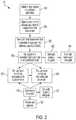
- FIG. 2is a block diagram depicting a pre-operative plan according to one embodiment.
- FIG. 3shows one embodiment of initiating a case request, as part of the pre-operative plan of FIG. 2 .
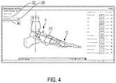
- FIG. 4shows one embodiment of assessing a deformity, as part of the pre-operative plan of FIG. 2 .
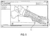
- FIG. 5shows one embodiment of correcting a deformity, as part of the pre-operative plan of FIG. 2 .
- FIG. 6shows one embodiment of an osteotomy to correct the deformity of FIG. 5 .
- FIG. 7shows an osteotomy plane according to the osteotomy of FIG. 6 .
- FIGS. 8 a and 8 bshow one embodiment of a cut guide according to the osteotomy of FIG. 6 .
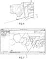
- FIG. 9shows another embodiment of a cut guide according to the osteotomy of FIG. 6 .
- FIG. 10shows a perspective view of the cut guide of FIG. 9 .
- FIG. 11shows one embodiment of a cut guide according to an osteotomy to correct a different deformity.
- FIG. 12shows one embodiment of evaluating bone density, as part of the pre-operative plan of FIG. 2
- FIG. 13shows one embodiment of projecting a plate profile over a corrected bone model, as part of the pre-operative plan of FIG. 2
- FIG. 14shows one embodiment of visualizing a screw trajectory through a corrected bone model, as part of the pre-operative plan of FIG. 2
- FIG. 15shows a method to define minimum and maximum plate dimensions, as part of the pre-operative plan of FIG. 2
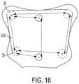
- FIG. 16shows boundaries calculated according to the method of FIG. 15 .
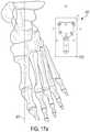
- FIG. 17 ashows one embodiment of a plate profile with minimum and maximum plate dimensions calculated according to the method of FIG. 15 .
- FIG. 17 bshows an enlarged view of the plate profile of FIG. 17 a.
- FIG. 18shows minimum plate dimensions calculated according to the method of FIG. 15 .
- FIG. 19shows maximum plate dimensions calculated according to the method of FIG. 15 .
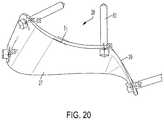
- FIG. 20shows one embodiment of a contoured plate with manipulated plate surfaces.
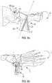
- FIG. 21shows one embodiment of a drill guide.
- FIG. 22shows one embodiment of visualizing an osteotomy, as part of the pre-operative plan of FIG. 2
- FIG. 23shows one embodiment of visualizing a patient-specific plating system on a corrected bone model, as part of the pre-operative plan of FIG. 2
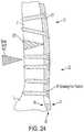
- FIG. 24shows one embodiment of visualizing a bone graft, as part of the pre-operative plan of FIG. 2
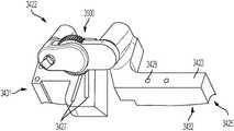
- FIG. 25shows a perspective view of yet another embodiment of a cut guide having first and second guide components coupled together via a joint mechanism.
- FIG. 26shows a partially exploded view of the cut guide of FIG. 25 .
- FIG. 27shows another perspective view of the cut guide of FIG. 25 with a front plane view of the joint mechanism.
- FIG. 28shows another embodiment of a joint mechanism that can be used to couple first and second guide components.
- FIG. 29shows another method to define minimum and maximum plate dimensions, as part of the pre-operative plan of FIG. 2 .
- FIG. 30shows tolerance ranges calculated according to the method of FIG. 29 .
- FIG. 31shows yet another method to define minimum and maximum plate dimensions, as part of the pre-operative plan of FIG. 2 .
- FIG. 32is a block diagram depicting a pre-operative plan according to a second embodiment.
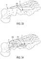
- FIG. 33shows one embodiment of generating a corrected bone model, as part of the pre-operative plan of FIG. 32 .
- FIG. 34shows one embodiment of identifying landmarks, as part of the pre-operative plan of FIG. 32 .
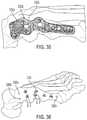
- FIG. 35shows one embodiment of determining a best-fit design, as part of the pre-operative plan of FIG. 32 .
- FIG. 36shows one embodiment of viewing a cluster of possible fixation hole locations, as part of the pre-operative plan of FIG. 32 .
- FIG. 37shows another embodiment of viewing a cluster of possible fixation hole locations, as part of the pre-operative plan of FIG. 32 .
- FIGS. 38-40show different embodiments of cut guides having different cutting slot designs.
- a surgeonmay choose to use a customized bone plate or a prefabricated bone plate.
- a fully-customized bone platemay provide better deformity correction, for example, when treating special situations or complex anatomy.
- a fully-customized bone plate having a preoperatively planned shape to match the outer surface of the patient's bone anatomymay also reduce pain and discomfort and/or promote the healing process. It also can help the surgeon ensure proper plate alignment and fixation during the surgery.
- FIG. 1shows a patient-specific plating system 10 according to one embodiment of the present invention.
- System 10includes a customized bone plate 20 comprising a body 23 having a first section 21 and a second section 22 .
- Body 23also includes a superior surface 27 and an inferior surface 29 (not shown).
- Inferior surface 29is a bone-contacting surface.
- body 23further includes fixation holes 30 adapted to receive fixation elements 60 .
- a customized bone platecan involve in-depth pre-operative planning
- One embodiment of a pre-operative plan 80is illustrated as a flowchart in FIG. 2 .
- the software applicationruns as an interactive platform in which a surgeon can design and customize a bone plate for a specific patient.
- the software applicationcould be web-based or installed by CD.
- the first step of pre-operative plan 80may comprise logging-in to the software application and initiating a case request 100 ( FIG. 2 ).
- each surgeonhas a unique username and password to reach a profile page.
- the surgeon's profile pagemay have a list of patients and associated cases. At this point, the surgeon may optionally modify an existing case or request to initiate a new case.
- the surgeoncan enter case details, e.g., patient information 110 , hospital information 120 , and surgeon information 130 , as shown in FIG. 3 .
- the surgeoncan also enter treatment information 140 including: anatomy 141 ; indication 142 , e.g., Charcot, midfoot, ankle, etc.; and deformity 143 , e.g., assessment required, multiple assessments required, correction required, etc.
- the surgeoncan select an expected delivery date 145 and enter any other design notes 146 .
- the surgeonmay note, “provide additional fixation hole at 2 nd metatarsal” based on a desired position for healing and/or experience from other similar cases.
- the surgeonmay indicate a need for a cut guide 421 , a bone graft 441 , and/or a drill guide 621 , as will be discussed below.
- the surgeoncan upload a scan of the patient's bone into the software application to create a deformed bone model 200 ( FIG. 2 ).
- a deformed bone modelthere is a first portion of bone 11 and a second portion of bone 12 which are in a deformed position with respect to each other.
- a computed tomography (“CT”) image or magnetic resonance imaging (“MRI”) image including 3D datamay be used such that the deformed bone model can closely mirror the patient's anatomy.
- CTcomputed tomography
- MRImagnetic resonance imaging
- 2D datacould also be used.
- the surgeonmay use a ‘Deformity Assessment Tool’ to calculate an apex point 310 of a deformity, also known as the ACA-CORA to those skilled in the art 300 ( FIG. 2 ). That is, the ‘Deformity Assessment Tool’ may be used to calculate an axis of correction of angulation (“ACA”) and a center of rotation of angulation (“CORA”) according to the deformed bone model ( FIG. 4 ).
- ACAaxis of correction of angulation
- CORAcenter of rotation of angulation
- the surgeonmay use standard measurement techniques known to those of ordinary skill in the art to calculate apex point 310 . For example, Principles of Deformity Correction , by Dror Paley, published in 2002 and hereby incorporated by reference in its entirety, discloses many such techniques.
- the surgeonmay use a ‘Deformity Correction Tool’ to generate a corrected bone model 400 ( FIG. 2 ).
- a corrected bone modelfirst and second bone portions 11 , 12 are in a corrected position different from the deformed position.
- the software applicationmay be used to calculate a Meary's angle of a deformity and simulate a correction procedure in order to generate a corrected bone model for Charcot or Midfoot indications.
- the surgeoncan project an axis of rotation R about apex point 310 onto the deformed bone model. Then, the surgeon can visualize deformation correction in real time by dragging and rotating the second bone portion 12 along the axis of rotation R for a certain distance ⁇ , as will be discussed further below ( FIG. 5 ).
- a closing wedgemay require an inverted “V” cut, e.g., for acute planar correction, or a complex double “V” cut, e.g., for acute two degree correction.
- a complex double “V” cutmay also be known as a “trapezoid” cut to those having ordinary skill in the art.
- FIG. 6shows an osteotomy plane O corresponding to a closing wedge osteotomy.
- An opening wedgegenerally requires a straight “V” cut, e.g., for acute rotational correction.
- the surgeonmay project the osteotomy plane O onto the deformed model, as shown in FIG. 7 .
- the osteotomy plane Opasses through apex point 310 .
- Osteotomy plane Omay define a bone cut out 802 that is to be removed, as will be discussed further below.
- the surgeoncan manipulate osteotomy plane O in the anterior, posterior, lateral, medial, and axial directions as desired.
- the surgeoncan also view the osteotomy plane O in a 2D or 3D plane.
- FIG. 8shows cut guide 422 for acute planar correction, which corresponds to the closing wedge osteotomy in FIG. 6 .
- Cut guide 422identifies bone cut out 802 required for proper alignment of first and second bone portions 11 , 12 and for proper plate placement ( FIG. 8 b ).
- the surgeonhas the option to indicate a need for a cut guide 421 ( FIG. 3 ).
- the software applicationcan create a complementary cut guide according to the corrected bone model 420 ( FIG. 2 ).
- the surgeonmay additionally modify the dimensions of the cut guide in real time using the software application.
- the surgeonmay design the cut guide to include another aperture adapted to receive a guiding pin and/or a fixation hole adapted to receive a fixation element.
- FIG. 38shows a cut guide 3800 having a fixation hole 3810 .
- the cutting slots 3827 of cut guide 3800extend up to the axis of rotation.
- FIG. 39shows a cut guide 3900 having a fixation hole 3910 ; however, the cutting slots 3927 are distinct in this “trimmed” embodiment.
- the surgeonmay also design the cut guide depending on the blade type.
- FIG. 40shows a cut guide 4000 having a fixation hole 4010 .
- the cutting slots 4027are open-ended and adapted to receive all blade types.
- cut guide 422has superior and inferior surfaces 423 , 425 .
- Inferior surface 425may be preoperatively planned to match the patient's bone anatomy in order to help ensure proper placement of cut guide 422 . In turn, this may also help a surgeon perform more accurate bone cuts.
- cut guide 422also has two angled cutting slots 427 for making a wedge shaped resection, the cutting slots 427 sized to receive an oscillating saw blade or similar cutting tool. In the preferred embodiment, slots 427 do not allow the saw blade to substantially vibrate during the resection procedure. Cut guide 422 may also have an aperture 428 adapted to receive a pin 429 . Pin 429 may help properly position the plate during the resection procedure. In some embodiments, cut guide 422 may also include a fixation hole 1428 adapted to receive a fixation element 1429 in order to help maintain the position of cut guide 422 during the resection procedure.
- cut guide 422may be used to perform a straight cut, closing wedge osteotomy.
- FIG. 9shows an alternative embodiment of a cut guide 432 corresponding to the closing wedge osteotomy in FIG. 6 .
- Cut guide 432has many similar features that are similarly numbered in comparison with cut guide 422 .
- cut guide 432has superior and inferior surfaces 433 , 435 where inferior surface 435 may also be preoperatively planned to match the patient's bone anatomy.
- Cut guide 432also has slots 437 adapted to receive a cutting tool.
- cut guide 432includes aperture 438 adapted to receive pin 439 and fixation hole 1438 adapted to receive fixation element 1439 .
- cute guide 432may include upper and lower portions 434 , 436 . Then, in order to perform accurate multi-angle cuts, the upper portion 434 of cut guide 432 may contact a proximal surface 1000 of a bone, opposite a distal surface 2000 ; while the lower portion 436 of cut guide 432 may contact one of two opposing medial sides 3000 of the bone.
- the surgeoncan make multiple multi-angle cuts using a single cut guide. This may be especially useful in cases where a complex double “V” cut is required.
- FIG. 25shows another embodiment of a cut guide 3422 corresponding to the closing wedge osteotomy in FIG. 6 .
- Cut guide 3422has many similar features that are similarly numbered in comparison with cut guides 422 , 432 .
- Cut guide 3422has superior and inferior surface 3423 , 3425 where inferior surface 3425 may be preoperatively planned to match the patient's bone anatomy.
- Cut guide 3422also has slots 3427 adapted to receive a cutting tool as well as apertures 3428 adapted to receive pins 4329 (not shown).
- Cut guide 3422may additionally have fixation holes adapted to receive fixation elements as discussed above in relation to different embodiments.
- Cut guide 3422includes a posterior section 3431 and an anterior section 3432 adapted to contact first and second bone portions 11 , 12 respectively.
- Posterior section 3431 and anterior section 3432may also be referred to as first and second cut guide components, respectively.
- the posterior and anterior sections 3431 , 3432are connected by a joint mechanism, i.e. gear module 3500 .
- Each posterior, anterior section 3431 , 3432includes a vertical projection 3450 with at least one peg hole 3452 .
- the distance between peg holes 3452 on posterior and anterior sections 3431 , 3432may be defined by distance A.
- Gear module 3500includes posterior and anterior sections 3511 , 3512 which may be aligned with the posterior and anterior sections 3431 , 3432 of cut guide 3422 .
- Each section 3511 , 3512 of gear module 3500may further include at least one peg 3552 insertable into the at least one peg hole 3452 in sections 3431 , 3432 of cut guide 3422 .
- the distance between the pegs 3552may be defined by distance B. As such, distances A and B should be equal such that pegs 3552 are insertable into peg holes 3452 .
- Gear module 3500may be used after the surgeon makes the desired bone cuts in order to manipulate or rearrange the first and second bone portions 11 , 12 from a deformed position into a corrected position.
- Gear module 3500may be designed such that anterior section 3512 has an operable end such as a hinged gear head 3522 , while posterior section 3511 includes an actuator 3521 configured to operate the hinged gear head 3522 . That is, upon actuation of actuator 3521 , hinged gear head 3522 will rotate about an axis G causing the distances A,B to decrease and forcing the posterior and anterior sections 3431 , 3432 of cut guide 3422 closer together such that first and second bone portions 11 , 12 may be arranged in the corrected position.
- FIG. 27shows an axis of rotation G corresponding to the center of the hinged gear head 3522 .
- the position of axis G and the location of pegs 3552 and corresponding peg holes 3452can be calculated according to the corrected bone model. That is, the software application will align the axis of rotation R and axis G. Accordingly, actuation of the hinged gear head 3522 may cause the anterior section 3512 of gear module 3500 to rotate about axis G and force the anterior section 3432 of cut guide 3422 to move toward the posterior section 3431 . As such, actuation of the hinged gear head 3522 may pull the first and second bone portions 11 , 12 from the deformed position into the corrected position.
- different embodiments of cut guide 3422may include more than two pegs 3522 and peg holes 3452 .
- the position of axis G and distances A, Bmay also be different.
- gear module 3500may be used to restrict motion of the first and second bone portions 11 , 12 after the resection procedure has been performed.
- the hinged design of gear head 3522can help the doctor ensure the rotation motion is about axis G such that the first and second bone portions 11 , 12 may be aligned in the corrected position.
- FIG. 28shows another embodiment of a joint mechanism, i.e. hinged module 3600 , that may connect posterior and anterior sections 3431 , 3432 of cut guide 3422 .
- hinged module 3600may also be used to rearrange the first and second bone portions 11 , 12 from the deformed position into the corrected position.
- the hinged module 3600similarly has posterior and anterior sections 3611 , 3612 and pegs 3652 insertable into peg holes 3452 .
- an end of the anterior section 3612may fit within an end of the posterior section 3611 and a pin 3621 may be inserted through both sections 3611 , 3612 along an axis of rotation J in order to form a hinged joint.
- the software applicationmay again be used to calculate the axis J and location of pegs 3652 and corresponding peg holes 3452 according to the corrected bone model. That is, the software application will align the axis of rotation R and axis J. As such, the surgeon may manipulate the anterior section 3611 of module 3600 by hand to rotate the anterior section 3432 of the cut guide toward the posterior section 3431 about axis J. Thus, the surgeon may manually arrange the first and second bone portions 11 , 12 in the corrected position.
- a ball-joint modulemay be used. Like the other joint mechanisms 3500 , 3600 , the ball-joint module may have pre-operatively planned posterior and anterior sections with pegs insertable into peg holes 3452 . Moreover, an end of the anterior section may be a sphere that fits within a cavity in an end of the posterior section, thereby forming a ball-joint. Insertion of the pegs into peg holes 3452 will restrict polyaxial motion of the ball-joint such that the anterior section of the ball-joint module can only rotate along a single ball-joint axis.
- the softwarewill design the location of pegs and corresponding peg holes 3452 according to the corrected bone model, such that the ball-joint axis is aligned with the axis of rotation R. Accordingly, the surgeon may manipulate the anterior section of the ball-joint module by hand to arrange the first and second bone portions 11 , 12 in the corrected position.
- a cut guide 1422 as shown in FIG. 11may be used to perform an opening wedge osteotomy for certain other cases.
- Cut guide 1422has many similar features that are similarly numbered in comparison with cut guides 422 , 432 . Accordingly, cut guide 1422 has superior and inferior surfaces 1423 , 1425 ; slots 1427 ; and aperture 1428 adapted to receive pin 1429 (not shown). Additionally, cut guide 1422 has at least one fixation hole 2428 adapted to receive fixation element 2429 (not shown).
- Cut guide 1422may optionally be designed to include posterior and anterior sections like cut guide 3422 , as well as a hinged module similar to gear module 3500 or ball-joint module 3600 that would force the posterior and anterior sections of the cut guide closer together in order to arrange the first and second bone portions 11 , 12 in the corrected position.
- the corrected bone modelmay show a gap 803 between first and second bone portions 11 , 12 .
- the surgeonmay require a bone graft 442 to fill gap 803 ( FIG. 23 ).
- the software applicationcan calculate the area of a bone graft according to the corrected bone model 440 ( FIG. 2 ).
- the software applicationcan also provide recommendations for ordering bone substitutes. For example, allograft material, polyetheretherketone, stainless steel, or titanium could be used.
- a surgeonmay use scan data from a patient's contralateral bone across the sagittal plane to generate the corrected bone model. In those cases, the surgeon may not need to create a deformed bone model 200 or use the Deformity Assessment Tool 300 , 350 ( FIG. 2 ). Still, the surgeon can design a patient-specific plating system.
- a surgeonmay use scan data from a database with a library of patient scans for creating the corrected bone model.
- the databasemay further include a library of corresponding bone plate designs for the patient scans. Those bone plate designs may be used as a template and further customized for a patient-specific plating system.
- a generic corrected bone modelmay be configured to fit what may be referred to as a 5% female and a 95% male such that it may be used for almost any patient.
- These generic modelsmay also be gender-specific or age-specific.
- the surgeonmay evaluate bone density. As one option, this can be done by performing comparative analysis between scan slices of a bone sample and the same bone in the patient 500 ( FIG. 2 ).
- the scan of the bone samplemay be obtained from a database with a library of patient scans.
- the surgeonmay perform segmentation analysis on a scan of the bone sample and a scan of the patient's bone to create scan slices.
- the scan slicemay have a thickness of 1 mm similar to X-ray images, but with more detail.
- the software applicationcan use an algorithm to compare the scan slices of the bone sample with the scan slices of the patient's bone.
- the same algorithmmay be used to distinguish and segregate each scan slice of the patient's bone with higher density, about the same density, or lower density as compared to the scan slice of the bone sample.
- Each of the scan slices of the patient's bonemay be assigned a color on the RGB color scale to indicate areas of relatively high, moderate, or low density compared to the bone sample.
- the colored scan slicesmay be combined to show bone volume.
- the 3D color schememay then be applied to the corrected bone model and create a color map for the surgeon to evaluate bone density.
- the software applicationcan provide the surgeon with visual information to evaluate bone density.
- the surgeoncan visualize the relative bone densities, where dark grey represents a relatively high density bone area ( 510 ), grey represents a relatively moderate density bone area ( 520 ), and light grey represents a relatively low density bone area ( 530 ). It is possible to use various colors instead of grey scale.
- the surgeoncan use Hounsfield unit conversion to compare scan slices of the patient's bone to each other 550 ( FIG. 2 ).
- the surgeoncan perform segmentation analysis on the scan of the patient's bone to create scan slices. Again, the scan slices may have a thickness of 1 mm. Then, the software application can calculate the bone density of each scan slice using Hounsfield values.
- U.S. Pat. Pub. Nos. 2015/0119987 and 2015/0080717hereby incorporated by reference in their entirety, disclose methods of deriving bone density from scan data using Hounsfield values.
- the software applicationcan use an algorithm to assign each scan slice a color on the RGB color scale to indicate areas of higher, about the same, or lower density as compared to each other. For example, green slices are more dense than yellow slices which are more dense than red slices. It is also possible to use a gray scale instead of a RGB color scale. Then, the colored scan slices may be combined to show bone volume and the 3D color scheme may be applied to the corrected bone model, as earlier discussed.
- Visual information showing relative bone densitiescan be very useful to a surgeon when he is deciding which areas of the bone can provide for proper alignment and fixation of a bone plate.
- the surgeoncan use color filtration options to show only relatively high, moderate, or low density bone areas. This is especially useful for patients with osteoporosis. Accordingly, the surgeon can ensure that fixation holes in a bone plate correspond to bone areas with relatively high or moderate density. It is not usually recommended to drill into areas of bone with relatively low density.
- the surgeoncan customize the bone plate 600 ( FIG. 2 ).
- the surgeonmay customize the number and location of fixation holes in the bone plate to correspond to areas of bone with relatively high or moderate density.
- the surgeoncan use the software application to project a plate template over the corrected bone model.
- the plate templatemay be a Talus Navicular Cuneiform and Metatarsal (TNCM) plate, a Navicular Cuneiform and Metatarsal (NCM) plate, a Cuneiform and Metatarsal (CM) plate.
- TNCMTalus Navicular Cuneiform and Metatarsal
- NCMNavicular Cuneiform and Metatarsal
- CMCuneiform and Metatarsal
- FIG. 13shows a profile 610 of a TNCM plate template projected over the corrected bone model.
- the surgeonhas the option to choose which plate type may be used 611 ( FIG. 3 ).
- the surgeoncan change plate types as desired in the options menu 612 ( FIG. 13 ).
- fixation element 60can be selected for procedures in the forefoot and midfoot.
- the software applicationmay illustrate the trajectory of fixation element 60 through the bone volume, as shown in FIG. 14 .
- the surgeoncan adjust the orientation of fixation element 60 and make other modifications.
- fixation elementsof different types or lengths.
- a surgeonmay choose to use mono-axial screws for lower density bone areas and poly-axial screws for higher density bone areas.
- the software applicationmay show the minimum number of fixation holes 30 for the selected plate template. That is, the software application will pre-determine the minimum size of a fixation hole 30 such that a fixation element can pivot during actuation relative to the rotation of the second bone portion 12 about axis R. Then, the surgeon can easily add or delete a fixation hole 30 , or change the location of a fixation hole 30 by clicking or dragging the cursor. However, it is recommended that profile 610 of the bone plate provide sufficient clearance given the number and location of fixation holes 30 .
- boundaries 620i.e. minimum and maximum plate dimensions, based on the number and location of fixation holes 30 .
- boundaries 620can be set based on a calculated maximum distance A,B,C,D,E, and F between each pair of fixation holes 30 . Accordingly, the surgeon may not move a fixation hole ( 30 ) beyond boundaries 620 ( FIG. 16 ).
- the surgeoncan project a 2D sketch plane 630 showing profile 610 of the bone plate.
- the surgeonmay pick three anatomic landmarks on the corrected bone model to place 2D sketch plane 630 . It is beneficial to use a 2D sketch plane instead of a 3D sketch plane because it requires much less data processing and computing power.
- 2D sketch plane 630the surgeon can project profile 610 of the bone plate over the corrected bone model, as shown in FIG. 17 a .
- profile 610 of the bone platemay automatically align with sketch axis 635 .
- An enlarged view of 2D sketch plane 630is shown in FIG. 17 b.
- the software applicationcan show circles 640 with short dashes and circles 650 with long dashes around each fixation hole 30 .
- Circles 640can help show the minimum dimensions of the plate.
- circles 640 for adjacent fixation holes 30can either be tangent to each other or not touching each other ( FIG. 18 ).
- circles 650can help show the maximum dimensions of the plate.
- Circles 650 for adjacent fixation holes 30can either be tangent to each other or overlapping each other ( FIG. 19 ).
- the dashed circlescan be helpful because they can provide real-time visual feedback to the surgeon as he defines the number and location of fixation holes ( 30 ) within boundaries 620 . In the software application, the surgeon can decide whether the dashed circles are visible sometimes, all the time, or not at all.
- FIG. 29shows another embodiment of a 2D sketch plane 1630 showing profile 610 of the bone plate.
- the 2D sketch plane 1630includes reference markers 1635 surrounding the fixation holes 30 that can be used similar to boundaries 620 . That is, each reference marker 1635 may have a predetermined tolerance range 1640 such that a fixation hole 30 cannot be moved beyond the minimum and maximum plate dimensions ( FIG. 30 ).
- a bone platemay have at least one relatively large fixation hole adapted to receive a fixation element at a plurality of angles such that a fixation element could pivot during insertion. Accordingly, the size of the circles 640 , 650 or the tolerance range 1640 may vary among fixation holes 30 .
- profile 610 of the bone platemay automatically regenerate. Now, the surgeon can translate, rotate, or otherwise manipulate profile 610 to better match patient bone anatomy. More particularly, profile 610 can be customized to better match the anatomy of the first and second bone portions 11 , 12 in the corrected position in the 2D plane.
- the surgeonmay also use the software application to test its clearance in a 3D plane ( FIG. 31 ).
- the software applicationmay project a smaller proxy surface 1650 and a larger proxy surface 1660 over the profile 610 wherein the proxy surfaces 1650 , 1660 correspond to the curvature of the corrected bone model.
- the smaller proxy surface 1650may represent the maximum curvature for clearance while the larger proxy surface 1660 may represent the minimum curvature for clearance.
- the profile 610may be customized so that it is disposed between the proxy surfaces 1650 , 1660 . This may help the bone plate 20 better match patient anatomy when the first and second bone portions 11 , 12 are in the corrected position. For example, the surgeon can make sure that a portion of the profile 610 a falls under proxy surface 1660 ; otherwise, portion 610 a may “stick out” creating a gap between the bone plate 20 and the bone due to poor matching.
- the surgeoncan also drag and manipulate surface contours of inferior surface 29 of the bone plate to bend the plate in a 3D plane, as shown in FIG. 20 . This can also help the surgeon design the bone plate to better match the anatomy of the first and second bone portions 11 , 12 in the corrected position.
- an inferior surface 29 a of the first section 21 of the bone platemay correspond well with an outer surface of the first bone portion 11
- an inferior surface 29 b of the second section 22 of the bone platemay correspond well with an outer surface of the second bone portion 12 ( FIG. 14 ).
- Thickness T 1 of the bone plateis defined by the linear distance between the superior and inferior surfaces 27 , 29 of the bone plate ( FIG. 20 ).
- the thickness T 1 of the bone platemay vary along the first and second sections 21 , 22 to better match patient anatomy. Still, it is important that the bone plate can be thick enough to provide enough threads, or other fastening means, for proper alignment and fixation.
- a protrusionmay create a support area to guide a fixation element into the fixation hole.
- a protrusionmay also provide additional threads, or other fastening means, for proper alignment and fixation.
- drill guide 621includes a superior surface 627 and an inferior surface 629 that may be pre-operatively planned to match the patient's anatomy. Drill guide 621 also has a thickness T 2 defined as the linear distance between the superior and inferior surfaces 627 , 629 of the drill guide 621 .
- drill guide 621has drill holes 630 adapted to receive a drilling tool.
- the location and orientation of drill holes 630correspond to the location and orientation of fixation holes 30 on the bone plate 20 .
- the angle of a drill hole 630corresponds to the trajectory of the fixation element upon insertion.
- the software applicationcan compute specific drill hole angle values based on the desired length of fixation elements in order to create a complementary drill guide.
- the software applicationcan also avoid interference between fixation elements and nerves.
- the resulting drill guidecan be used to direct insertion of fixation elements at a pre-specified drill hole angle.
- the surgeonWhen the surgeon is entering treatment information 100 , the surgeon has the option to indicate a need for a drill guide 621 ( FIG. 3 ).
- the software applicationcan create a complementary drill guide according to the corrected bone model 620 ( FIG. 2 ).
- the surgeonmay review and approve a complete design for the patient-specific plating system 700 ( FIG. 2 ). In the preferred embodiment, this may include simulating an operative technique on the corrected bone model. Moreover, in some embodiments, the simulation may be performed in the operating room such that any necessary patient-specific modifications can be made intraoperatively using, for example, additive manufacturing.
- first and second bone portions 11 , 12are in a deformed position with respect to each other. Then, the surgeon can calculate apex point 310 of the deformity and optionally perform an osteotomy to remove bone cut out 802 . As shown in FIG. 22 , the first bone portion 11 is above apex point 310 and the second bone portion 12 is below apex point 310 .
- the surgeoncan simulate positioning the customized bone plate 20 such that the inferior surface 29 a of the first section 21 of the bone plate contacts the outer surface of first bone portion 11 , and the second section 22 of the bone plate extends below apex point 310 .
- the surgeonmay secure the first section 21 of the bone plate to the first bone portion 11 in the simulation.
- the surgeoncould insert a first fixation element 60 a through a first fixation hole 30 a in the first section 21 of the bone plate, and into the first bone portion 11 .
- the surgeonmay use additional fixation elements 60 to secure the first section 21 of the bone plate to the first bone portion 11 .
- Heads 61 a of the fixation elements in the first section 21 of the bone platemay be almost flush with the superior surface 27 of the bone plate.
- the surgeoncan simulate inserting a second fixation element 60 b through a second fixation hole 30 b in the second section 22 of the bone plate, and into at least a part of the second bone portion 12 ( FIG. 23 ).
- the second fixation element 60 bmight be longer than the first fixation element 60 a .
- the second fixation hole 30 bmight be larger than the first fixation hole 30 a .
- a large or elongated fixation holemay be desirable because it allows the fixation element to pivot during insertion.
- Simulated actuation of the second fixation element 60 bmay cause the second bone portion 12 to rotate along the axis of rotation R for distance ⁇ such that first and second bone portions 11 , 12 are in the corrected position with respect to each other.
- the inferior surface 29 b of the second section 22 of the bone platecontacts the outer surface of the second bone portion 12 ( FIG. 24 ).
- the surgeonmay use additional fixation elements 60 to secure the first and second sections 21 , 22 of the bone plate to the first and second bone portions 11 , 12 .
- heads 61 of all fixation elementsmay be flush with the superior surface 27 of the bone plate.
- Gap 803is sized to receive bone graft 442 , as previously discussed.
- the surgeoncan evaluate the customized details of the bone plate and make any desired changes to the patient-specific plating system before manufacturing. More particularly, the surgeon may alter the number or location of fixation holes, the orientation of fixation holes/elements, the type or length of fixation elements, the profile of the bone plate, the superior and inferior surfaces of the bone plate, the thickness of the bone plate, and/or any surface protrusions on the plate. For example, it may be particularly important for fixation hole 30 b to be of sufficient size to allow the second fixation element 60 b to pivot during actuation, as the first and second bone portions 11 , 12 are arranged in the corrected position. The surgeon may also modify requests for a cut guide, a bone graft, and/or a drill guide.
- a file including the designcan be exported for manufacturing.
- the time between initiating a case request 100 and approval 700may be approximately four working days ( FIG. 2 ).
- pre-operative plan 80may be performed by a third party instead of the surgeon.
- a Stryker design representativemay perform the deformity assessment 300 , 350 ; deformity correction 400 ; bone density evaluation 500 , 550 ; and plate customization 600 ( FIG. 2 ).
- a third partyit is recommended that the surgeon pay careful attention to the design notes 146 when entering treatment information 100 ( FIG. 3 ). It is also recommended that the surgeon carefully review and approve the complete design of the patient-specific plating system 700 . In many cases, there may be correspondence between the surgeon and the third party regarding modifications to the customized bone plate before the system is approved.
- Customized bone plate 20 of FIG. 1can be created using a computer numerical control (“CNC”) milling type operation or additive manufacturing.
- Body 23 of the bone platecan be made of a biocompatible material such as titanium or stainless steel.
- the time for manufacturingmay be approximately eight working days.
- the total time to create a patient-specific plating systemwould be, for example, approximately twelve working days.
- a patient-specific plating systemmay provide better patient matching as a result of in-depth pre-operative planning. Also, the creation and use of a customized bone plate may offer significant improvements over standard bone plates.
- the deformity assessment and correction tools described hereinallow a surgeon to design a customized bone plate that can correct special situations or complex anatomy. With these tools, the surgeon can visualize both a deformed bone model and a corrected bone model. This may be useful when correcting Charcot, midfoot, and ankle deformities, as well as other types of bone deformity in other parts of the body.
- the customization of a profile and inferior surface of a bone plate according to a corrected bone modelcan reduce pain and discomfort for the patient. This is because the profile and inferior surface of the plate may closely match the patient anatomy, particularly, the outer surfaces of the first and second bone portions in a corrected position.
- the surgeoncan also visualize relative bone densities. This allows the surgeon to customize the number and location of fixation holes in a bone plate such that the bone plate can be secured to higher density bone areas. This can promote healing because first and second bone portions can be properly aligned and secured in the corrected position.
- the software applicationcan enforce predetermined boundaries to ensure proper dimensions of the bone plate given the number and location of fixation holes. This prevents the bone plate being too small or too large for a specific patient.
- the surgeonmay also request: a complementary cut guide which may improve the accuracy of bone-cuts in an osteotomy procedure; a complementary bone graft assessment which can fill a gap between first and second bone portions in a corrected position; and a complementary drill guide which may facilitate plate fixation.
- the complementary cut guidemay be especially useful because the inferior surface may be preoperatively planned to better match the patient's anatomy in order to help ensure proper placement of the cut guide.
- the surgeonmay be able to make more accurate bone cuts, as well as multi-angle bone cuts when using a single cut guide.
- the customized bone plateis desirable to surgeons because it is quickly realizable (in about two weeks) and easy to manufacture.
- the customized bone platemay be included as part of a surgical kit for the surgeon.
- the surgical kitmay further include at least two fixation elements, a cut guide, a bone knife, a drill guide, a drill, and/or a screw driver.
- the method of using the patient specific plating systemis also advantageous because the surgeon can gradually rotate the second bone portion into a corrected position with better precision, compared to existing methods. Although the method was described in reference to bone deformities in the foot, the same method could be applied to correct other deformities in other parts of the body.
- a prefabricated or standard bone plateIt may be desirable to use a prefabricated bone plate, rather than a semi- or fully-customized bone plate, in order to reduce the time and expense associated with the surgery. In many applications, a prefabricated bone plate will sufficiently hold the first and second bone portions in the corrected position for healing.
- the selection processcan involve detailed pre-operative planning
- One embodiment of a pre-operative plan 8000is illustrated as a flowchart in FIG. 32 . Similar to pre-operative plan 80 previously described, many steps of pre-operative plan 8000 also use a software application.
- a surgeonmay generate a corrected bone model 1100 , in order to identify landmark locations on the corrected bone model 2100 . ( FIG. 32 ). It is recommended that the surgeon choose at least three landmark locations 3300 on the bone model. As shown in FIG. 33 , the surgeon has identified nine landmark locations 3300 . Each landmark location 3300 is chosen to correspond to a desired fixation hole location 3310 . Often, it would be desirable for the landmark locations 3300 to correspond to areas of the first and second bone portions 11 , 12 having higher relative densities.
- the surgeoncan use the software application to access a library of prefabricated bone plate designs 3100 .
- the librarycan hold several hundreds of prefabricated plate designs having different fixation hole location combinations.
- the software applicationcan then be used to compare proximity of the landmark locations 3300 with the fixation hole locations 3310 on the various prefabricated plate designs 4100 . ( FIG. 32 ). To do so, the software application may calculate the average distance between each landmark location 3300 and each fixation hole location 3310 for each of the prefabricated plate designs. The lowest average distance would likely result in the best matching prefabricated plate design 3320 . This plate design 3320 can then be projected onto the corrected bone model for 3D visualization and evaluation. ( FIG. 34 ).
- the software applicationcould display a plurality of plate designs 3320 a - c that have an average proximity within a predefined tolerance level that would be considered adequate for healing. ( FIG. 35 ). Then, the surgeon could visually compare those plate designs and select the plate design with the best-fit.
- the surgeonmay only select three landmark locations.
- These three landmarks 3300could be “locked in” such that the software application will only display plate designs having fixation holes matching those landmark locations.
- the software applicationwould then display a cluster 3330 of other possible fixation hole locations corresponding to the remaining possible plate designs 4200 . ( FIG. 32 ). As shown in FIG.
- the three landmarks 3300 a , 3300 b , 3300 cappear as a single option and could be colored, for example, in red; while six or more holes in between the extreme proximal and distal ends appear as a cluster of possible fixation hole locations.
- each fixation hole locationhas three possible options corresponding to three possible plate designs. The options could be shown in grey scale or color-coded, for example, green options g for the green plate design; purple options p for the purple plate design; and orange options (not labeled) for the orange plate design.
- the software applicationmay also provide an additional indicator for a suggested fixation hole location.
- the surgeonmay choose a fourth landmark location from the options in one of the clusters. ( FIG. 37 ).
- the software applicationcan automatically adjust the other possible fixation hole locations. Generally, the surgeon will continue selecting landmarks in order of decreasing significance until the best-fit plate is determined.
- the available optionsmay increase, decrease, or reposition as more landmarks are identified. For example, if the fourth landmark location is chosen at the suggested fixation hole locations; the first, second, and third landmarks may reposition or display a new cluster of green, purple, and orange options. Desirably, it is possible for the surgeon to change the landmark locations and/or prioritize the landmarks in real time.
- the surgeoncan select the best matching plate design based on the chosen landmark locations 3300 .
- the plate designcan then be evaluated for review and approval 6100 ( FIG. 32 ).
- the surgeoncan use the software application to simulate the correction procedure, in order to verify and test that the prefabricated plate design is adequate for healing, for example, within a predefined confidence interval.
- the fixation hole locationcould still be optimized for the specific patient. Therefore, going through the selection process according to the embodiment described above would likely reduce patient pain and discomfort and/or promote healing.
- a semi-customized bone platemay include some patient-specific features for better patient matching, while keeping resource costs low. It may also allow for design of the bone plate from information derived from 2D patient images such as X-rays as opposed to 3D bone models.
- the Stryker Orthopedics Modeling and Analytics system (“SOMA”)is a population-based design environment featuring a large database of bone morphology, including size, shape, density, and inner and outer cortical boundaries, drawn from diverse populations. SOMA can be used in a combination with information derived from X-ray images of a particular patient in order to fill-in 3D information that is not available from 2D X-ray images. In such cases, SOMA in combination with X-ray images can be used to design an implant such as a bone plate that has both patient-specific and standard contact surfaces and fixation features.
- a prefabricated bone platecan be modified to provide better matching between the inferior surface of the bone plate and the outer surface of each of the first and second bone portions when the first and second bone portions are in the corrected position.
- It designing a bone plate for the footit may be beneficial to include a polymer on a portion of the inferior surface of the bone plate, particularly at the talus. This may be desirable to minimize resistance during fusion of the joint. It also may be desirable to facilitate proper plate alignment and fixation.
- Bone quality datamay be derived from an image (or data relating to an image) of at least one joint.
- the image (or image data)can be obtained in a variety of ways, including by performing any medical imaging method known in the art, or by obtaining the image data from a collection and/or database.
- the image datamay be obtained by performing a CT scan. Additional suitable imaging methods include MRI, Electrical Impedance Tomography (“EIT”), Dual-Energy X-ray Absorptiometry (“DXA” or “DEXA”), X-ray, ultrasound, and nuclear imaging, for example.
- the image datamay further comprise a combination of one or more different kinds of image data, for instance a composite image data that comprises both CT and MRI image data, for example.
- the image data obtainedmay correspond to either a single individual or to a population of individuals.
- the image datamay correspond to a joint of the individual for whom the press-fit is being optimized in accordance with the method(s) described herein.
- the parameters of the bone resectionare being determined on a patient-specific basis such that the parameters optimize the press-fit between the individual anatomy and the articular implant.
- bone qualitymay be derived from data representative of a population, for instance a representative or average data corresponding to a particular population of individuals.
- the populationmay represent a class or sub-class of individuals, for instance members of an age-range, a gender, a class of individuals who suffer from a particular joint or knee ailment, any other suitable population that is relevant to articular implants, or any combination thereof.
- the SOMA databasemay be further used, for example, by normalizing a set of data relevant to the patient of interest onto a phantom tissue model. In this way, image data taken from a population may be used to derive the relevant bone quality and to optimize the engagement between the implant and the patient's bone.
- bone quality informationcan be derived by a variety of methods for calculating or estimating bone properties from the imaging modalities previously described, including CT, X-ray, MRI, DEXA, etc. Such methods of deriving bone quality information are described in U.S. Pat. Pub. No. 2015/0080717 titled “Patient Specific Bone Preparation for Consistent Effective Feature Engagement,” the disclosure of which is hereby incorporated by reference herein in its entirety.
Landscapes
- Health & Medical Sciences (AREA)
- Orthopedic Medicine & Surgery (AREA)
- Life Sciences & Earth Sciences (AREA)
- Surgery (AREA)
- Engineering & Computer Science (AREA)
- Heart & Thoracic Surgery (AREA)
- General Health & Medical Sciences (AREA)
- Biomedical Technology (AREA)
- Veterinary Medicine (AREA)
- Medical Informatics (AREA)
- Molecular Biology (AREA)
- Animal Behavior & Ethology (AREA)
- Nuclear Medicine, Radiotherapy & Molecular Imaging (AREA)
- Public Health (AREA)
- Neurology (AREA)
- Dentistry (AREA)
- Oral & Maxillofacial Surgery (AREA)
- Robotics (AREA)
- Surgical Instruments (AREA)
Abstract
Description
Claims (18)
Priority Applications (5)
| Application Number | Priority Date | Filing Date | Title |
|---|---|---|---|
| US15/910,120US11033333B2 (en) | 2017-04-06 | 2018-03-02 | Plate selection user interface and design tool with database |
| EP18165822.0AEP3384865B1 (en) | 2017-04-06 | 2018-04-05 | Plate selection user interface and design tool with database |
| US17/242,682US12161420B2 (en) | 2017-04-06 | 2021-04-28 | Plate selection user interface and design tool with database |
| US18/940,302US20250064524A1 (en) | 2017-04-06 | 2024-11-07 | Plate Selection User Interface and Design Tool with Database |
| US19/024,004US20250186121A1 (en) | 2017-04-06 | 2025-01-16 | Plate Selection User Interface and Design Tool with Database |
Applications Claiming Priority (2)
| Application Number | Priority Date | Filing Date | Title |
|---|---|---|---|
| US201762482422P | 2017-04-06 | 2017-04-06 | |
| US15/910,120US11033333B2 (en) | 2017-04-06 | 2018-03-02 | Plate selection user interface and design tool with database |
Related Child Applications (1)
| Application Number | Title | Priority Date | Filing Date |
|---|---|---|---|
| US17/242,682DivisionUS12161420B2 (en) | 2017-04-06 | 2021-04-28 | Plate selection user interface and design tool with database |
Publications (2)
| Publication Number | Publication Date |
|---|---|
| US20180289423A1 US20180289423A1 (en) | 2018-10-11 |
| US11033333B2true US11033333B2 (en) | 2021-06-15 |
Family
ID=61906725
Family Applications (4)
| Application Number | Title | Priority Date | Filing Date |
|---|---|---|---|
| US15/910,120Active2038-10-16US11033333B2 (en) | 2017-04-06 | 2018-03-02 | Plate selection user interface and design tool with database |
| US17/242,682Active2039-12-16US12161420B2 (en) | 2017-04-06 | 2021-04-28 | Plate selection user interface and design tool with database |
| US18/940,302PendingUS20250064524A1 (en) | 2017-04-06 | 2024-11-07 | Plate Selection User Interface and Design Tool with Database |
| US19/024,004PendingUS20250186121A1 (en) | 2017-04-06 | 2025-01-16 | Plate Selection User Interface and Design Tool with Database |
Family Applications After (3)
| Application Number | Title | Priority Date | Filing Date |
|---|---|---|---|
| US17/242,682Active2039-12-16US12161420B2 (en) | 2017-04-06 | 2021-04-28 | Plate selection user interface and design tool with database |
| US18/940,302PendingUS20250064524A1 (en) | 2017-04-06 | 2024-11-07 | Plate Selection User Interface and Design Tool with Database |
| US19/024,004PendingUS20250186121A1 (en) | 2017-04-06 | 2025-01-16 | Plate Selection User Interface and Design Tool with Database |
Country Status (2)
| Country | Link |
|---|---|
| US (4) | US11033333B2 (en) |
| EP (1) | EP3384865B1 (en) |
Cited By (2)
| Publication number | Priority date | Publication date | Assignee | Title |
|---|---|---|---|---|
| US11931106B2 (en) | 2019-09-13 | 2024-03-19 | Treace Medical Concepts, Inc. | Patient-specific surgical methods and instrumentation |
| US11986251B2 (en) | 2019-09-13 | 2024-05-21 | Treace Medical Concepts, Inc. | Patient-specific osteotomy instrumentation |
Families Citing this family (13)
| Publication number | Priority date | Publication date | Assignee | Title |
|---|---|---|---|---|
| US11033335B2 (en)* | 2017-12-13 | 2021-06-15 | Formus Labs Limited | Placement of orthopaedic implant fixation apparatus |
| US11783102B2 (en)* | 2019-04-30 | 2023-10-10 | BabySteps Orthopedics Inc. | Predictive modeling platform for serial casting to correct orthopedic deformities |
| EP3968872A4 (en)* | 2019-05-13 | 2023-04-19 | Wright Medical Technology, Inc. | Surgical tools and methods of use |
| ES2895389A1 (en)* | 2020-08-21 | 2022-02-21 | Pedreno Conrado Miguel Bano | Method implemented by computer planning and surgical navigation for osteosynthesis surgeries, corrective osteotomies and tumor surgery with navigable measurement guides, navigated polyxial instruments, wedges and plates of custom osteosynthesis (Machine-translation by Google Translate, not legally binding) |
| FR3113575B1 (en)* | 2020-09-02 | 2023-08-04 | Abys Medical | Method for generating digital models of osteosynthesis plates specific to the morphology of the patient |
| CN112370156B (en)* | 2020-11-13 | 2022-03-11 | 山东中医药大学 | Memory alloy reset external fixing system based on virtual reset and use method |
| US12064127B2 (en)* | 2020-11-18 | 2024-08-20 | Fusion Orthopedics USA, LLC | Surgical cutting block including multiple cut guides |
| TR202103267A2 (en)* | 2021-02-26 | 2021-03-22 | Oezguer Sinan Yaldiz | Custom software supported 3D Printing bone cutting guide creation system |
| US12178515B2 (en) | 2021-04-26 | 2024-12-31 | Arthrex, Inc. | Systems and methods for density calibration |
| CN114098969B (en)* | 2022-01-27 | 2022-05-06 | 北京威高智慧科技有限公司 | Osteotomy diagnostic system, osteotomy diagnostic method, device and medium |
| US20240189034A1 (en)* | 2022-12-08 | 2024-06-13 | Albert C. Lynch | Conformation Based Bone Model Generation and Associated Surgical Techniques |
| US11963686B1 (en) | 2023-04-20 | 2024-04-23 | Fusion Orthopedics USA, LLC | Surgical systems and methods including cutting and aligning guides for performing an osteotomy |
| US12303140B2 (en) | 2023-04-20 | 2025-05-20 | Fusion Orthopedics USA, LLC | Surgical systems and methods including cutting and aligning guides for performing an osteotomy |
Citations (120)
| Publication number | Priority date | Publication date | Assignee | Title |
|---|---|---|---|---|
| US2825329A (en) | 1953-02-04 | 1958-03-04 | Orville S Caesar | Internal fixation of fractures |
| US3709218A (en) | 1970-04-24 | 1973-01-09 | W Halloran | Combination intramedullary fixation and external bone compression apparatus |
| US3900025A (en) | 1974-04-24 | 1975-08-19 | Jr Walter P Barnes | Apparatus for distracting or compressing longitudinal bone segments |
| US4235428A (en) | 1979-03-15 | 1980-11-25 | Davis Jack H | Bone transfixation pin guide |
| US4719907A (en) | 1987-03-18 | 1988-01-19 | Orthospec, Inc. | Orthopedic pin placement guide |
| US4969886A (en) | 1987-01-23 | 1990-11-13 | Endre Cziffer | Disposable fixing means especially for fixing factured small tubular bones externally |
| US5139550A (en) | 1988-05-09 | 1992-08-18 | British Telecommunications Public Limited Company | Method of making fluoride glass optical coupler |
| US5529075A (en) | 1994-09-12 | 1996-06-25 | Clark; David | Fixation device and method for repair of pronounced hallux valgus |
| US5916219A (en) | 1997-02-10 | 1999-06-29 | Matsuno; Shigeo | Tibial plateau resection guide |
| US5921986A (en) | 1998-02-06 | 1999-07-13 | Bonutti; Peter M. | Bone suture |
| US6183477B1 (en) | 1998-09-04 | 2001-02-06 | Smith & Nephew, Inc. | Attachment tool for drill guide |
| US6221073B1 (en) | 1999-08-20 | 2001-04-24 | Kinetikos Medical, Inc. | Wrist fusion apparatus and method |
| US6287307B1 (en) | 2000-07-31 | 2001-09-11 | Shalom Y. Abboudi | Apparatus and methods for clamping split bone sections |
| US20030135212A1 (en) | 2002-01-11 | 2003-07-17 | Y. Chow James C. | Rod and plate bone fixation device for persons with osteophorosis |
| US20040116930A1 (en)* | 2002-06-10 | 2004-06-17 | O'driscoll Shawn W. | Bone plates |
| US6932818B2 (en) | 2003-10-30 | 2005-08-23 | Alfred F. Behrens | Intramedullary nail-based bone fracture treatment |
| US20050216010A1 (en) | 2001-06-04 | 2005-09-29 | Michelson Gary K | Method for installation of dynamic, single-lock anterior cervical plate system having non-detachably fastened and moveable segments |
| US20050234472A1 (en) | 2004-04-19 | 2005-10-20 | Huebner Randall J | Placement of fasteners into bone |
| US20050273112A1 (en)* | 2004-05-26 | 2005-12-08 | Mcnamara Michael G | Three-dimensional osteotomy device and method for treating bone deformities |
| US20060015102A1 (en) | 2004-07-15 | 2006-01-19 | Toullec Eric R M | Fastener implant for osteosynthesis of fragments of a first metatarsal bone that is broken or osteotomized in its proximal portion and a corresponding osteosynthesis method |
| US7090676B2 (en) | 2002-11-19 | 2006-08-15 | Acumed Llc | Adjustable bone plates |
| US20060195198A1 (en) | 2005-02-22 | 2006-08-31 | Anthony James | Interactive orthopaedic biomechanics system |
| US20060241592A1 (en) | 2005-03-31 | 2006-10-26 | Mark Myerson | Mid-foot fixation plate |
| US7147640B2 (en) | 2003-03-12 | 2006-12-12 | Acumed Llc | External fixator |
| US20060285931A1 (en) | 2005-06-16 | 2006-12-21 | Dean Dennis C | Combination drill guide and clamping device |
| US7153309B2 (en) | 2002-11-19 | 2006-12-26 | Acumed Llc | Guide system for bone-repair devices |
| US7189237B2 (en) | 2002-11-19 | 2007-03-13 | Acumed Llc | Deformable bone plates |
| US7198628B2 (en) | 2004-06-30 | 2007-04-03 | Depuy Products, Inc. | Adjustable humeral cutting guide |
| US7235079B2 (en) | 2004-11-18 | 2007-06-26 | Acumed Llc | Composite bone fasteners |
| US20070225715A1 (en) | 2006-03-24 | 2007-09-27 | Depuy Products, Inc. | Fastening system for internal fixation |
| US20070276386A1 (en) | 2003-09-29 | 2007-11-29 | Darin Gerlach | Bone plate systems using provisional fixation |
| US7347861B2 (en) | 2001-01-31 | 2008-03-25 | Grampian Health Board | Bone fixture apparatus and jig |
| US20080119895A1 (en) | 2006-11-20 | 2008-05-22 | Thierry Manceau | Locking bone plate with bushing anti-rotation feature |
| US20080183218A1 (en) | 2007-01-31 | 2008-07-31 | Nuvasive, Inc. | System and Methods for Spinous Process Fusion |
| US7410489B2 (en) | 1998-09-28 | 2008-08-12 | Daos Limited | Internal cord fixation device |
| US20090029320A1 (en) | 2005-04-08 | 2009-01-29 | Cendres & Metaux Sa | Extracoronal Attachment and Method for the Production Thereof |
| US7537596B2 (en) | 2003-06-20 | 2009-05-26 | Acumed Llc | Bone plates with intraoperatively tapped apertures |
| US7537604B2 (en) | 2002-11-19 | 2009-05-26 | Acumed Llc | Bone plates with slots |
| US7537603B2 (en) | 2002-07-22 | 2009-05-26 | Acumed Llc | Bone fusion system |
| US20090228049A1 (en) | 2008-03-09 | 2009-09-10 | Park Sangdo | Connecting Cannulated Bone Screws |
| US20090254126A1 (en)* | 2008-04-04 | 2009-10-08 | Skeletal Dynamics Llc | Compression/distraction osteotomy system, plate, method, drill guide and saw guide |
| US7621920B2 (en) | 2005-06-13 | 2009-11-24 | Zimmer, Inc. | Adjustable cut guide |
| US20090306675A1 (en) | 2008-05-30 | 2009-12-10 | Wright Medical Technology, Inc. | Drill guide assembly |
| US20090312802A1 (en) | 2007-09-13 | 2009-12-17 | Dasilva Manuel | System for making a bone repair |
| US7635365B2 (en) | 2003-08-28 | 2009-12-22 | Ellis Thomas J | Bone plates |
| US20090326591A1 (en) | 2008-01-29 | 2009-12-31 | Spencer Jr Edwin E | System and method to position and secure fractured bones |
| US7648508B2 (en)* | 2004-11-30 | 2010-01-19 | Stryker Trauma S.A. | Bone plating implants, instruments and methods |
| US7658741B2 (en) | 2005-06-16 | 2010-02-09 | Zimmer, Inc. | Multi-positionable cut guide |
| US7717945B2 (en) | 2002-07-22 | 2010-05-18 | Acumed Llc | Orthopedic systems |
| US7794467B2 (en) | 2003-11-14 | 2010-09-14 | Smith & Nephew, Inc. | Adjustable surgical cutting systems |
| US7837717B2 (en) | 2006-03-24 | 2010-11-23 | Depuy Products, Inc. | Fastening system for internal fixation |
| US20100318086A1 (en) | 2008-02-16 | 2010-12-16 | Mitchell Winemaker | Method and apparatus for treating periprosthetic fractures of the distal femur |
| US7857836B2 (en) | 2005-07-13 | 2010-12-28 | Acumed Llc | Bone plates with movable locking elements |
| US20110009866A1 (en) | 2009-07-09 | 2011-01-13 | Orthohelix Surgical Designs, Inc. | Osteotomy plate, plate driver and method for their use |
| US7914532B2 (en) | 2005-10-21 | 2011-03-29 | Acumed Llc | Orthopedic rod with locking aperture |
| US7927332B2 (en) | 2004-11-12 | 2011-04-19 | Acumed Llc | Bone reamer |
| US7955388B2 (en) | 2006-11-01 | 2011-06-07 | Acumed Llc | Orthopedic connector system |
| US20110144698A1 (en)* | 2009-12-11 | 2011-06-16 | Daniel Buchbinder | Mandibular Fixation Plate |
| US20110213376A1 (en)* | 2010-02-26 | 2011-09-01 | Biomet Sports Medicine, Llc | Patient-Specific Osteotomy Devices and Methods |
| US20110245930A1 (en) | 2008-10-29 | 2011-10-06 | Smith & Nephew, Inc. | Porous surface layers with increased surface roughness and implants incorporating the same |
| US8043297B2 (en) | 2004-11-03 | 2011-10-25 | Synthes Usa, Llc | Aiming arm for bone plates |
| US20120130434A1 (en) | 2009-02-24 | 2012-05-24 | Wright Medical Technology, Inc. | Orthopedic surgical guide |
| US20120130686A1 (en) | 2010-11-23 | 2012-05-24 | Rainer Graumann | Method to determine a parameter of a fixing element for an implant to be affixed to a bone |
| US8187308B2 (en) | 2008-02-29 | 2012-05-29 | Sixfix Inc. | Internal joint distraction method |
| US8231662B2 (en) | 2006-10-17 | 2012-07-31 | Acumed Llc | Bone fixation with a strut-stabilized bone plate |
| US8231627B2 (en) | 2007-07-19 | 2012-07-31 | Acumed Llc | Insertion tool for bone plates |
| US8262706B2 (en) | 2007-07-11 | 2012-09-11 | Stryker Trauma Gmbh | Device for creating a bone implant |
| US8328809B2 (en) | 2010-01-07 | 2012-12-11 | Zimmer, Inc. | Bone plate fixation system |
| US20130018424A1 (en) | 2011-07-13 | 2013-01-17 | Michael Subik | Osteotomy and arthrodesis treatment system |
| US8372078B2 (en) | 2006-06-30 | 2013-02-12 | Howmedica Osteonics Corp. | Method for performing a high tibial osteotomy |
| US8398678B2 (en) | 2010-03-15 | 2013-03-19 | Arthrex, Inc. | Hallux valgus repairs using suture-button construct |
| US8398717B2 (en) | 2008-11-10 | 2013-03-19 | Acumed Llc | Partial or complete prosthetic replacement arthroplasty of the distal radioulnar joint |
| US8403966B2 (en) | 2008-11-24 | 2013-03-26 | Mbd Medical Llc | Clavicle plate and screws |
| US8425575B2 (en) | 2010-09-27 | 2013-04-23 | Acumed Llc | Bone plate supported by a leg member and used as a lever |
| US8500745B2 (en) | 2004-02-20 | 2013-08-06 | DePuy Synthes Products, LLC | Aiming device for inserting stable-angle, long screws in the articular region of a bone |
| US8506597B2 (en) | 2011-10-25 | 2013-08-13 | Biomet Sports Medicine, Llc | Method and apparatus for interosseous membrane reconstruction |
| US20130211463A1 (en) | 2010-09-28 | 2013-08-15 | Olympus Terumo Biomaterials Corp. | Bone plate and bone plate system |
| US20130226248A1 (en) | 2012-03-23 | 2013-08-29 | Osteomed Llc | Locking Plate with Screw Fixation from Opposite Cortex |
| US8523919B2 (en) | 2010-09-27 | 2013-09-03 | Acumed Llc | Targeting guide with a radiopaque marker to facilitate positioning a bone plate on bone |
| US20130245602A1 (en) | 2003-07-15 | 2013-09-19 | Spinal Generations, Llc | Method and device for delivering medicine to bone |
| US20130296872A1 (en)* | 2012-05-03 | 2013-11-07 | Andrew Charles Davison | Surgical Guide with Cut Resistant Inserts |
| US8579900B2 (en) | 2010-01-06 | 2013-11-12 | Chia-Hao Hsu | Minimally invasive skeletal fixation device |
| US8585744B2 (en) | 2009-07-14 | 2013-11-19 | Imds Corporation | Joint arthrodesis and arthroplasty |
| US8628531B2 (en) | 2006-01-27 | 2014-01-14 | Smith & Nephew, Inc. | Assemblies for the reduction of a fracture |
| US8652142B2 (en)* | 2006-04-28 | 2014-02-18 | Acumed Llc | Osteotomy systems |
| US20140058466A1 (en) | 2012-08-27 | 2014-02-27 | Materialise Nv | Surgical guiding tools and systems and methods of manufacturing surgical guiding tools |
| US8685030B2 (en) | 2007-06-26 | 2014-04-01 | Brainlab Ag | Pre-adjusting adjustable bone cutting blocks to enable navigation of the incision plane with respect to reference objects |
| US20140107781A1 (en) | 2009-11-20 | 2014-04-17 | Zimmer Knee Creations, Inc. | Implantable devices for subchondral treatment of joint pain |
| US20140180341A1 (en) | 2012-12-21 | 2014-06-26 | Mako Surgical Corp. | Methods and systems for planning and performing an osteotomy |
| US20140336658A1 (en)* | 2012-12-27 | 2014-11-13 | Wright Medical Technology, Inc. | Ankle replacement system and method |
| US20150032168A1 (en) | 2012-02-16 | 2015-01-29 | Paragon 28, Inc. | Charco-resis implant, alignment instrument, system and method of use |
| US20150045837A1 (en) | 2012-09-06 | 2015-02-12 | Orthohelix Surgical Designs, Inc. | Orthopedic dual pocket compression plate and method of surgery |
| US20150051876A1 (en) | 2011-12-14 | 2015-02-19 | Stryker Leibinger Gmbh & Co. Kg | Technique for generating a bone plate design |
| US20150051650A1 (en) | 2012-04-18 | 2015-02-19 | Materialise N.V. | Orthopedic bone fixation systems and methods |
| US20150057665A1 (en)* | 2012-05-08 | 2015-02-26 | Zimmer, Inc. | Porous spacers, instruments, and methods for foot and ankle fusion |
| US20150080717A1 (en) | 2013-09-18 | 2015-03-19 | Stryker Corporation | Patient specific bone preparation for consistent effective fixation feature engagement |
| US20150112343A1 (en) | 2012-03-08 | 2015-04-23 | Trimed, Incorporated | System and method for treating bone fractures |
| US20150119987A1 (en) | 2013-10-28 | 2015-04-30 | Stryker Corporation | Implant design using heterogeneous bone properties and probabilistic tools to determine optimal geometries for fixation features |
| US9060790B2 (en) | 2010-04-20 | 2015-06-23 | Virginia Commonwealth University | Tibiotalar arthrodesis guide |
| US20150223824A1 (en) | 2014-02-12 | 2015-08-13 | Biomet Manufacturing, Llc. | Jig with targeting feature |
| US20150257899A1 (en)* | 2012-12-27 | 2015-09-17 | Wright Medical Technology, Inc. | Ankle replacement system and method |
| US20150272598A1 (en)* | 2012-12-12 | 2015-10-01 | Obl S.A. | Implant and guide |
| US20150305752A1 (en)* | 2014-04-25 | 2015-10-29 | Biomet Manufacturing, Llc | HTO Guide With Optional Guided ACL/PCL Tunnels |
| US9186163B2 (en) | 2012-06-04 | 2015-11-17 | Depuy Mitek, Llc | Methods and devices for forming bone tunnels |
| US20150366594A1 (en) | 2012-12-14 | 2015-12-24 | Universiteit Gent | Articular fracture fixation system and method |
| US9241744B2 (en) | 2011-08-15 | 2016-01-26 | Amei Technologies, Inc. | Targeting assembly for a compression nail system |
| US20160022336A1 (en) | 2013-03-08 | 2016-01-28 | Edward Richard Bateman | Apparatus for Humeral Fracture Repair |
| US20160030064A1 (en) | 2013-03-15 | 2016-02-04 | Paragon 28, Inc. | Intramedullary nail fixation guides, devices and methods of use |
| US20160038186A1 (en) | 2013-03-15 | 2016-02-11 | Cycla Orthopedics Ltd. | Devices and methods for bone anchoring |
| US20160051298A1 (en) | 2014-08-21 | 2016-02-25 | Valeris Medical, Llc | Bone plate and method of use |
| US9320553B2 (en) | 2011-10-18 | 2016-04-26 | Biomet Manufacturing, Llc | Compressive distal humerus plating system |
| US9370386B2 (en) | 2009-11-27 | 2016-06-21 | DePuy Synthes Products, Inc. | Plating concept for distal radial fractures |
| WO2016112469A1 (en) | 2015-01-12 | 2016-07-21 | Ao Technology Ag | Method for manufacturing an auxiliary device suitable for the manufacture of a patient customized implant |
| US9402636B2 (en) | 2007-04-19 | 2016-08-02 | Howmedica Osteonics Corp. | Cutting guide with internal distraction |
| US9414873B2 (en) | 2012-01-05 | 2016-08-16 | The Cleveland Clinic Foundation | Modular bone fixation system |
| US20160287335A1 (en)* | 2013-11-12 | 2016-10-06 | Makoto Goto | Manufacturing method of bone cutting assist device, manufacturing program of bone cutting assist device, and bone cutting assist device |
| US9474539B2 (en) | 2011-04-29 | 2016-10-25 | Biomet Manufacturing, Llc | Patient-specific convertible guides |
| US20170027628A1 (en) | 2015-07-28 | 2017-02-02 | University-Industry Cooperation Group Of Kyung Hee University | Drug delivery implant implanted into bone |
| US20170119405A1 (en) | 2015-11-02 | 2017-05-04 | First Ray, LLC | Orthopedic fastener, retainer, and guide |
| US20180289380A1 (en) | 2015-12-16 | 2018-10-11 | Tornier, Inc. | Patient specific instruments and methods for joint prosthesis |
Family Cites Families (11)
| Publication number | Priority date | Publication date | Assignee | Title |
|---|---|---|---|---|
| US6139550A (en) | 1997-02-11 | 2000-10-31 | Michelson; Gary K. | Skeletal plating system |
| AUPP830499A0 (en)* | 1999-01-22 | 1999-02-18 | Cryptych Pty Ltd | Method and apparatus for delivering bio-active compounds to specified sites in the body |
| US7811312B2 (en)* | 2002-12-04 | 2010-10-12 | Morphographics, Lc | Bone alignment implant and method of use |
| US20070038303A1 (en)* | 2006-08-15 | 2007-02-15 | Ebi, L.P. | Foot/ankle implant and associated method |
| EP2467098A4 (en)* | 2009-08-19 | 2015-07-08 | Illuminoss Medical Inc | Devices and methods for bone alignment, stabilization and distraction |
| EP2583246B1 (en)* | 2010-06-16 | 2019-01-30 | A² Surgical | Method and system of automatic determination of geometric elements characterizing a bone deformation from 3d image |
| US9020223B2 (en)* | 2010-06-16 | 2015-04-28 | A2 Surgical | Method for determining bone resection on a deformed bone surface from few parameters |
| WO2013116812A1 (en)* | 2012-02-03 | 2013-08-08 | Orthohub, Inc. | External fixator deformity correction systems and methods |
| US9226796B2 (en)* | 2012-08-03 | 2016-01-05 | Stryker Corporation | Method for detecting a disturbance as an energy applicator of a surgical instrument traverses a cutting path |
| US9204937B2 (en)* | 2013-02-19 | 2015-12-08 | Stryker Trauma Gmbh | Software for use with deformity correction |
| EP4027922A4 (en)* | 2019-09-13 | 2023-10-04 | MIOS Marketing LLC, DBA RedPoint Medical 3D | Patient-specific surgical methods and instrumentation |
- 2018
- 2018-03-02USUS15/910,120patent/US11033333B2/enactiveActive
- 2018-04-05EPEP18165822.0Apatent/EP3384865B1/enactiveActive
- 2021
- 2021-04-28USUS17/242,682patent/US12161420B2/enactiveActive
- 2024
- 2024-11-07USUS18/940,302patent/US20250064524A1/enactivePending
- 2025
- 2025-01-16USUS19/024,004patent/US20250186121A1/enactivePending
Patent Citations (133)
| Publication number | Priority date | Publication date | Assignee | Title |
|---|---|---|---|---|
| US2825329A (en) | 1953-02-04 | 1958-03-04 | Orville S Caesar | Internal fixation of fractures |
| US3709218A (en) | 1970-04-24 | 1973-01-09 | W Halloran | Combination intramedullary fixation and external bone compression apparatus |
| US3900025A (en) | 1974-04-24 | 1975-08-19 | Jr Walter P Barnes | Apparatus for distracting or compressing longitudinal bone segments |
| US4235428A (en) | 1979-03-15 | 1980-11-25 | Davis Jack H | Bone transfixation pin guide |
| US4969886A (en) | 1987-01-23 | 1990-11-13 | Endre Cziffer | Disposable fixing means especially for fixing factured small tubular bones externally |
| US4719907A (en) | 1987-03-18 | 1988-01-19 | Orthospec, Inc. | Orthopedic pin placement guide |
| US5139550A (en) | 1988-05-09 | 1992-08-18 | British Telecommunications Public Limited Company | Method of making fluoride glass optical coupler |
| US5529075A (en) | 1994-09-12 | 1996-06-25 | Clark; David | Fixation device and method for repair of pronounced hallux valgus |
| US5916219A (en) | 1997-02-10 | 1999-06-29 | Matsuno; Shigeo | Tibial plateau resection guide |
| US5921986A (en) | 1998-02-06 | 1999-07-13 | Bonutti; Peter M. | Bone suture |
| US6183477B1 (en) | 1998-09-04 | 2001-02-06 | Smith & Nephew, Inc. | Attachment tool for drill guide |
| US7410489B2 (en) | 1998-09-28 | 2008-08-12 | Daos Limited | Internal cord fixation device |
| US6221073B1 (en) | 1999-08-20 | 2001-04-24 | Kinetikos Medical, Inc. | Wrist fusion apparatus and method |
| US6287307B1 (en) | 2000-07-31 | 2001-09-11 | Shalom Y. Abboudi | Apparatus and methods for clamping split bone sections |
| US7347861B2 (en) | 2001-01-31 | 2008-03-25 | Grampian Health Board | Bone fixture apparatus and jig |
| US20050216010A1 (en) | 2001-06-04 | 2005-09-29 | Michelson Gary K | Method for installation of dynamic, single-lock anterior cervical plate system having non-detachably fastened and moveable segments |
| US20030135212A1 (en) | 2002-01-11 | 2003-07-17 | Y. Chow James C. | Rod and plate bone fixation device for persons with osteophorosis |
| US20040116930A1 (en)* | 2002-06-10 | 2004-06-17 | O'driscoll Shawn W. | Bone plates |
| US8425574B2 (en) | 2002-07-22 | 2013-04-23 | Acumed, Llc | Bone fixation with a bone plate attached to a fastener assembly |
| US7717945B2 (en) | 2002-07-22 | 2010-05-18 | Acumed Llc | Orthopedic systems |
| US9414871B2 (en) | 2002-07-22 | 2016-08-16 | Acumed Llc | Bone plates with movable locking elements |
| US7537603B2 (en) | 2002-07-22 | 2009-05-26 | Acumed Llc | Bone fusion system |
| US9308033B2 (en) | 2002-07-22 | 2016-04-12 | Acumed Llc | Adjustable bone plates |
| US7704251B2 (en) | 2002-11-19 | 2010-04-27 | Acumed Llc | Adjustable bone plates |
| US7153309B2 (en) | 2002-11-19 | 2006-12-26 | Acumed Llc | Guide system for bone-repair devices |
| US7189237B2 (en) | 2002-11-19 | 2007-03-13 | Acumed Llc | Deformable bone plates |
| US7537604B2 (en) | 2002-11-19 | 2009-05-26 | Acumed Llc | Bone plates with slots |
| US7090676B2 (en) | 2002-11-19 | 2006-08-15 | Acumed Llc | Adjustable bone plates |
| US7326212B2 (en) | 2002-11-19 | 2008-02-05 | Acumed Llc | Bone plates with reference marks |
| US7147640B2 (en) | 2003-03-12 | 2006-12-12 | Acumed Llc | External fixator |
| US7537596B2 (en) | 2003-06-20 | 2009-05-26 | Acumed Llc | Bone plates with intraoperatively tapped apertures |
| US20130245602A1 (en) | 2003-07-15 | 2013-09-19 | Spinal Generations, Llc | Method and device for delivering medicine to bone |
| US7635365B2 (en) | 2003-08-28 | 2009-12-22 | Ellis Thomas J | Bone plates |
| US20070276386A1 (en) | 2003-09-29 | 2007-11-29 | Darin Gerlach | Bone plate systems using provisional fixation |
| US6932818B2 (en) | 2003-10-30 | 2005-08-23 | Alfred F. Behrens | Intramedullary nail-based bone fracture treatment |
| US7794467B2 (en) | 2003-11-14 | 2010-09-14 | Smith & Nephew, Inc. | Adjustable surgical cutting systems |
| US8500745B2 (en) | 2004-02-20 | 2013-08-06 | DePuy Synthes Products, LLC | Aiming device for inserting stable-angle, long screws in the articular region of a bone |
| US20050234472A1 (en) | 2004-04-19 | 2005-10-20 | Huebner Randall J | Placement of fasteners into bone |
| US7578825B2 (en) | 2004-04-19 | 2009-08-25 | Acumed Llc | Placement of fasteners into bone |
| US20050273112A1 (en)* | 2004-05-26 | 2005-12-08 | Mcnamara Michael G | Three-dimensional osteotomy device and method for treating bone deformities |
| US7198628B2 (en) | 2004-06-30 | 2007-04-03 | Depuy Products, Inc. | Adjustable humeral cutting guide |
| US20060015102A1 (en) | 2004-07-15 | 2006-01-19 | Toullec Eric R M | Fastener implant for osteosynthesis of fragments of a first metatarsal bone that is broken or osteotomized in its proximal portion and a corresponding osteosynthesis method |
| US8043297B2 (en) | 2004-11-03 | 2011-10-25 | Synthes Usa, Llc | Aiming arm for bone plates |
| US7927332B2 (en) | 2004-11-12 | 2011-04-19 | Acumed Llc | Bone reamer |
| US7235079B2 (en) | 2004-11-18 | 2007-06-26 | Acumed Llc | Composite bone fasteners |
| US7648508B2 (en)* | 2004-11-30 | 2010-01-19 | Stryker Trauma S.A. | Bone plating implants, instruments and methods |
| US20060195198A1 (en) | 2005-02-22 | 2006-08-31 | Anthony James | Interactive orthopaedic biomechanics system |
| US20060241592A1 (en) | 2005-03-31 | 2006-10-26 | Mark Myerson | Mid-foot fixation plate |
| US20090029320A1 (en) | 2005-04-08 | 2009-01-29 | Cendres & Metaux Sa | Extracoronal Attachment and Method for the Production Thereof |
| US7621920B2 (en) | 2005-06-13 | 2009-11-24 | Zimmer, Inc. | Adjustable cut guide |
| US7658741B2 (en) | 2005-06-16 | 2010-02-09 | Zimmer, Inc. | Multi-positionable cut guide |
| US20060285931A1 (en) | 2005-06-16 | 2006-12-21 | Dean Dennis C | Combination drill guide and clamping device |
| US7857836B2 (en) | 2005-07-13 | 2010-12-28 | Acumed Llc | Bone plates with movable locking elements |
| US7914532B2 (en) | 2005-10-21 | 2011-03-29 | Acumed Llc | Orthopedic rod with locking aperture |
| US8628531B2 (en) | 2006-01-27 | 2014-01-14 | Smith & Nephew, Inc. | Assemblies for the reduction of a fracture |
| US20070225715A1 (en) | 2006-03-24 | 2007-09-27 | Depuy Products, Inc. | Fastening system for internal fixation |
| US7837717B2 (en) | 2006-03-24 | 2010-11-23 | Depuy Products, Inc. | Fastening system for internal fixation |
| US8652142B2 (en)* | 2006-04-28 | 2014-02-18 | Acumed Llc | Osteotomy systems |
| US8372078B2 (en) | 2006-06-30 | 2013-02-12 | Howmedica Osteonics Corp. | Method for performing a high tibial osteotomy |
| US8231662B2 (en) | 2006-10-17 | 2012-07-31 | Acumed Llc | Bone fixation with a strut-stabilized bone plate |
| US7955388B2 (en) | 2006-11-01 | 2011-06-07 | Acumed Llc | Orthopedic connector system |
| US20080119895A1 (en) | 2006-11-20 | 2008-05-22 | Thierry Manceau | Locking bone plate with bushing anti-rotation feature |
| US20080183218A1 (en) | 2007-01-31 | 2008-07-31 | Nuvasive, Inc. | System and Methods for Spinous Process Fusion |
| US9402636B2 (en) | 2007-04-19 | 2016-08-02 | Howmedica Osteonics Corp. | Cutting guide with internal distraction |
| US8685030B2 (en) | 2007-06-26 | 2014-04-01 | Brainlab Ag | Pre-adjusting adjustable bone cutting blocks to enable navigation of the incision plane with respect to reference objects |
| US8262706B2 (en) | 2007-07-11 | 2012-09-11 | Stryker Trauma Gmbh | Device for creating a bone implant |
| US8231627B2 (en) | 2007-07-19 | 2012-07-31 | Acumed Llc | Insertion tool for bone plates |
| US8475504B2 (en) | 2007-07-19 | 2013-07-02 | Acumed Llc | Method of bone fixation with slender spanning members disposed outside bone |
| US8821580B2 (en) | 2007-09-13 | 2014-09-02 | Swiss Ortho, Llc | System for making a bone repair |
| US20090312802A1 (en) | 2007-09-13 | 2009-12-17 | Dasilva Manuel | System for making a bone repair |
| US20090326591A1 (en) | 2008-01-29 | 2009-12-31 | Spencer Jr Edwin E | System and method to position and secure fractured bones |
| US20100318086A1 (en) | 2008-02-16 | 2010-12-16 | Mitchell Winemaker | Method and apparatus for treating periprosthetic fractures of the distal femur |
| US8187308B2 (en) | 2008-02-29 | 2012-05-29 | Sixfix Inc. | Internal joint distraction method |
| US20090228049A1 (en) | 2008-03-09 | 2009-09-10 | Park Sangdo | Connecting Cannulated Bone Screws |
| US20090254126A1 (en)* | 2008-04-04 | 2009-10-08 | Skeletal Dynamics Llc | Compression/distraction osteotomy system, plate, method, drill guide and saw guide |
| US8313492B2 (en) | 2008-05-30 | 2012-11-20 | Wright Medical Technology, Inc. | Drill guide assembly |
| US20090306675A1 (en) | 2008-05-30 | 2009-12-10 | Wright Medical Technology, Inc. | Drill guide assembly |
| US8764763B2 (en) | 2008-05-30 | 2014-07-01 | Wright Medical Technology, Inc. | Procedure for repairing foot injury |
| US20110245930A1 (en) | 2008-10-29 | 2011-10-06 | Smith & Nephew, Inc. | Porous surface layers with increased surface roughness and implants incorporating the same |
| US8398717B2 (en) | 2008-11-10 | 2013-03-19 | Acumed Llc | Partial or complete prosthetic replacement arthroplasty of the distal radioulnar joint |
| US8403966B2 (en) | 2008-11-24 | 2013-03-26 | Mbd Medical Llc | Clavicle plate and screws |
| US20120130434A1 (en) | 2009-02-24 | 2012-05-24 | Wright Medical Technology, Inc. | Orthopedic surgical guide |
| US20110009866A1 (en) | 2009-07-09 | 2011-01-13 | Orthohelix Surgical Designs, Inc. | Osteotomy plate, plate driver and method for their use |
| US8585744B2 (en) | 2009-07-14 | 2013-11-19 | Imds Corporation | Joint arthrodesis and arthroplasty |
| US20140107781A1 (en) | 2009-11-20 | 2014-04-17 | Zimmer Knee Creations, Inc. | Implantable devices for subchondral treatment of joint pain |
| US9370386B2 (en) | 2009-11-27 | 2016-06-21 | DePuy Synthes Products, Inc. | Plating concept for distal radial fractures |
| US20110144698A1 (en)* | 2009-12-11 | 2011-06-16 | Daniel Buchbinder | Mandibular Fixation Plate |
| US8579900B2 (en) | 2010-01-06 | 2013-11-12 | Chia-Hao Hsu | Minimally invasive skeletal fixation device |
| US8328809B2 (en) | 2010-01-07 | 2012-12-11 | Zimmer, Inc. | Bone plate fixation system |
| US20110213376A1 (en)* | 2010-02-26 | 2011-09-01 | Biomet Sports Medicine, Llc | Patient-Specific Osteotomy Devices and Methods |
| US8398678B2 (en) | 2010-03-15 | 2013-03-19 | Arthrex, Inc. | Hallux valgus repairs using suture-button construct |
| US9060790B2 (en) | 2010-04-20 | 2015-06-23 | Virginia Commonwealth University | Tibiotalar arthrodesis guide |
| US8523919B2 (en) | 2010-09-27 | 2013-09-03 | Acumed Llc | Targeting guide with a radiopaque marker to facilitate positioning a bone plate on bone |
| US8425575B2 (en) | 2010-09-27 | 2013-04-23 | Acumed Llc | Bone plate supported by a leg member and used as a lever |
| US20130211463A1 (en) | 2010-09-28 | 2013-08-15 | Olympus Terumo Biomaterials Corp. | Bone plate and bone plate system |
| US20120130686A1 (en) | 2010-11-23 | 2012-05-24 | Rainer Graumann | Method to determine a parameter of a fixing element for an implant to be affixed to a bone |
| US8886496B2 (en) | 2010-11-23 | 2014-11-11 | Siemens Aktiengesellschaft | Method to determine a parameter of a fixing element for an implant to be affixed to a bone |
| US9474539B2 (en) | 2011-04-29 | 2016-10-25 | Biomet Manufacturing, Llc | Patient-specific convertible guides |
| US20130018424A1 (en) | 2011-07-13 | 2013-01-17 | Michael Subik | Osteotomy and arthrodesis treatment system |
| US9241744B2 (en) | 2011-08-15 | 2016-01-26 | Amei Technologies, Inc. | Targeting assembly for a compression nail system |
| US20160235445A1 (en) | 2011-10-18 | 2016-08-18 | Biomet Manufacturing, Llc | Compressive distal humerus plating system |
| US9320553B2 (en) | 2011-10-18 | 2016-04-26 | Biomet Manufacturing, Llc | Compressive distal humerus plating system |
| US8506597B2 (en) | 2011-10-25 | 2013-08-13 | Biomet Sports Medicine, Llc | Method and apparatus for interosseous membrane reconstruction |
| US20150051876A1 (en) | 2011-12-14 | 2015-02-19 | Stryker Leibinger Gmbh & Co. Kg | Technique for generating a bone plate design |
| US9414873B2 (en) | 2012-01-05 | 2016-08-16 | The Cleveland Clinic Foundation | Modular bone fixation system |
| US20150032168A1 (en) | 2012-02-16 | 2015-01-29 | Paragon 28, Inc. | Charco-resis implant, alignment instrument, system and method of use |
| US20150112343A1 (en) | 2012-03-08 | 2015-04-23 | Trimed, Incorporated | System and method for treating bone fractures |
| US20130226248A1 (en) | 2012-03-23 | 2013-08-29 | Osteomed Llc | Locking Plate with Screw Fixation from Opposite Cortex |
| US20150051650A1 (en) | 2012-04-18 | 2015-02-19 | Materialise N.V. | Orthopedic bone fixation systems and methods |
| US20130296872A1 (en)* | 2012-05-03 | 2013-11-07 | Andrew Charles Davison | Surgical Guide with Cut Resistant Inserts |
| US20150057665A1 (en)* | 2012-05-08 | 2015-02-26 | Zimmer, Inc. | Porous spacers, instruments, and methods for foot and ankle fusion |
| US9186163B2 (en) | 2012-06-04 | 2015-11-17 | Depuy Mitek, Llc | Methods and devices for forming bone tunnels |
| US20140058466A1 (en) | 2012-08-27 | 2014-02-27 | Materialise Nv | Surgical guiding tools and systems and methods of manufacturing surgical guiding tools |
| US20150045837A1 (en) | 2012-09-06 | 2015-02-12 | Orthohelix Surgical Designs, Inc. | Orthopedic dual pocket compression plate and method of surgery |
| US9339279B2 (en) | 2012-12-12 | 2016-05-17 | Obl S.A. | Implant and guide |
| US20150272598A1 (en)* | 2012-12-12 | 2015-10-01 | Obl S.A. | Implant and guide |
| US20150366594A1 (en) | 2012-12-14 | 2015-12-24 | Universiteit Gent | Articular fracture fixation system and method |
| US20140180341A1 (en) | 2012-12-21 | 2014-06-26 | Mako Surgical Corp. | Methods and systems for planning and performing an osteotomy |
| US20140336658A1 (en)* | 2012-12-27 | 2014-11-13 | Wright Medical Technology, Inc. | Ankle replacement system and method |
| US20150257899A1 (en)* | 2012-12-27 | 2015-09-17 | Wright Medical Technology, Inc. | Ankle replacement system and method |
| US20160022336A1 (en) | 2013-03-08 | 2016-01-28 | Edward Richard Bateman | Apparatus for Humeral Fracture Repair |
| US20160030064A1 (en) | 2013-03-15 | 2016-02-04 | Paragon 28, Inc. | Intramedullary nail fixation guides, devices and methods of use |
| US20160038186A1 (en) | 2013-03-15 | 2016-02-11 | Cycla Orthopedics Ltd. | Devices and methods for bone anchoring |
| US20150080717A1 (en) | 2013-09-18 | 2015-03-19 | Stryker Corporation | Patient specific bone preparation for consistent effective fixation feature engagement |
| US20150119987A1 (en) | 2013-10-28 | 2015-04-30 | Stryker Corporation | Implant design using heterogeneous bone properties and probabilistic tools to determine optimal geometries for fixation features |
| US20160287335A1 (en)* | 2013-11-12 | 2016-10-06 | Makoto Goto | Manufacturing method of bone cutting assist device, manufacturing program of bone cutting assist device, and bone cutting assist device |
| US20150223824A1 (en) | 2014-02-12 | 2015-08-13 | Biomet Manufacturing, Llc. | Jig with targeting feature |
| US20150305752A1 (en)* | 2014-04-25 | 2015-10-29 | Biomet Manufacturing, Llc | HTO Guide With Optional Guided ACL/PCL Tunnels |
| US20160051298A1 (en) | 2014-08-21 | 2016-02-25 | Valeris Medical, Llc | Bone plate and method of use |
| WO2016112469A1 (en) | 2015-01-12 | 2016-07-21 | Ao Technology Ag | Method for manufacturing an auxiliary device suitable for the manufacture of a patient customized implant |
| US20170027628A1 (en) | 2015-07-28 | 2017-02-02 | University-Industry Cooperation Group Of Kyung Hee University | Drug delivery implant implanted into bone |
| US20170119405A1 (en) | 2015-11-02 | 2017-05-04 | First Ray, LLC | Orthopedic fastener, retainer, and guide |
| US20180289380A1 (en) | 2015-12-16 | 2018-10-11 | Tornier, Inc. | Patient specific instruments and methods for joint prosthesis |
Non-Patent Citations (4)
| Title |
|---|
| Dobbe, et al., "Patient-Tailored Plate for Bone Fixation and Accurate 3D Positioning in Corrective Osteotomy", vol. 51, No. 1-2, Medical & Biological Engineering & Computing, Feb. 2013, pp. 19-27. |
| Extended European Search Report and Written Opinion for EP Application No. 18165822.0, dated Sep. 5, 2018. |
| Extended European Search Report and Written Opinion for EP Application No. 18178063.6, dated Apr. 8, 2019. |
| Partial European Search Report and Written Opinion for EP Application No. 18178063.6, dated Nov. 19, 2018. |
Cited By (2)
| Publication number | Priority date | Publication date | Assignee | Title |
|---|---|---|---|---|
| US11931106B2 (en) | 2019-09-13 | 2024-03-19 | Treace Medical Concepts, Inc. | Patient-specific surgical methods and instrumentation |
| US11986251B2 (en) | 2019-09-13 | 2024-05-21 | Treace Medical Concepts, Inc. | Patient-specific osteotomy instrumentation |
Also Published As
| Publication number | Publication date |
|---|---|
| EP3384865A1 (en) | 2018-10-10 |
| US20250064524A1 (en) | 2025-02-27 |
| US20180289423A1 (en) | 2018-10-11 |
| US20250186121A1 (en) | 2025-06-12 |
| EP3384865B1 (en) | 2024-05-22 |
| US20210244477A1 (en) | 2021-08-12 |
| US12161420B2 (en) | 2024-12-10 |
Similar Documents
| Publication | Publication Date | Title |
|---|---|---|
| US12161420B2 (en) | Plate selection user interface and design tool with database | |
| US11986251B2 (en) | Patient-specific osteotomy instrumentation | |
| US20240341773A1 (en) | Patient-specific surgical methods and instrumentation | |
| CN114072088B (en) | Surgical planning system with automated defect sizing | |
| US10849665B2 (en) | Snap-fit cutting guides and plating systems | |
| US20190105058A1 (en) | Cutting template and a method of manufacturing the same | |
| Popescu et al. | Design and 3D printing customized guides for orthopaedic surgery–lessons learned | |
| EP4197474A1 (en) | Method and system for planning an osteotomy procedure | |
| Rosseels et al. | Corrective osteotomies using patient-specific 3D-printed guides: a critical appraisal | |
| Pijpker et al. | Accuracy assessment of pedicle and lateral mass screw insertion assisted by customized 3D-printed drill guides: a human cadaver study | |
| US20240108414A1 (en) | Apparatus, system, and method for generating patient-specific implants and/or instrumentation | |
| García-Sevilla et al. | Patient-specific desktop 3D-printed guides for pelvic tumour resection surgery: A precision study on cadavers | |
| US20250195081A1 (en) | Patient-specific osteotomy systems, methods, and instrumentation | |
| Bachy et al. | Early Results of 3-dimensional planning and customized cutting guides for the treatment of severe Madelung deformity | |
| US20250057547A1 (en) | Apparatus, system, and method for patient-specific systems, methods, and instrumentation | |
| US20240252180A1 (en) | Apparatus, system, and method for osteotomies | |
| Gellrich et al. | Computer assisted oral and maxillofacial reconstruction | |
| US20230310013A1 (en) | Apparatus, system, and method for patient-specific instrumentation | |
| US20240008880A1 (en) | Apparatus, system, and method for patient-specific systems, methods, and instrumentation | |
| Kang et al. | Is the mirroring technology reliable in the use of computer-aided design for orbital reconstruction? three-dimensional analysis of asymmetry in the orbits | |
| US20230363773A1 (en) | Apparatus, system, and method for patient-specific methods and instrumentation | |
| US20240099778A1 (en) | Patient-specific soft tissue rearrangement | |
| US20240252181A1 (en) | Apparatus, system, and method for instrumentation | |
| US20240277350A1 (en) | Apparatus, system, and method for patient-specific harvesting guide | |
| van der Laan | Optimizing Revision Total Knee Arthroplasty: An In-Depth Analysis of 3D Planning Prediction and Patient-Specific Instruments for Revision Surgery |
Legal Events
| Date | Code | Title | Description |
|---|---|---|---|
| FEPP | Fee payment procedure | Free format text:ENTITY STATUS SET TO UNDISCOUNTED (ORIGINAL EVENT CODE: BIG.); ENTITY STATUS OF PATENT OWNER: LARGE ENTITY | |
| AS | Assignment | Owner name:STRYKER EUROPEAN HOLDINGS I, LLC, MICHIGAN Free format text:ASSIGNMENT OF ASSIGNORS INTEREST;ASSIGNORS:SINGH, MANOJ KUMAR;KUMAR, ANUP;SIGNING DATES FROM 20180308 TO 20180607;REEL/FRAME:046067/0283 | |
| STPP | Information on status: patent application and granting procedure in general | Free format text:DOCKETED NEW CASE - READY FOR EXAMINATION | |
| STPP | Information on status: patent application and granting procedure in general | Free format text:NON FINAL ACTION MAILED | |
| STPP | Information on status: patent application and granting procedure in general | Free format text:RESPONSE TO NON-FINAL OFFICE ACTION ENTERED AND FORWARDED TO EXAMINER | |
| STPP | Information on status: patent application and granting procedure in general | Free format text:NON FINAL ACTION MAILED | |
| STPP | Information on status: patent application and granting procedure in general | Free format text:NOTICE OF ALLOWANCE MAILED -- APPLICATION RECEIVED IN OFFICE OF PUBLICATIONS | |
| STPP | Information on status: patent application and granting procedure in general | Free format text:PUBLICATIONS -- ISSUE FEE PAYMENT RECEIVED | |
| STPP | Information on status: patent application and granting procedure in general | Free format text:PUBLICATIONS -- ISSUE FEE PAYMENT VERIFIED | |
| STCF | Information on status: patent grant | Free format text:PATENTED CASE | |
| AS | Assignment | Owner name:STRYKER EUROPEAN HOLDINGS III, LLC, DELAWARE Free format text:NUNC PRO TUNC ASSIGNMENT;ASSIGNOR:STRYKER EUROPEAN HOLDINGS I, LLC;REEL/FRAME:056969/0771 Effective date:20210219 Owner name:STRYKER EUROPEAN OPERATIONS HOLDINGS LLC, MICHIGAN Free format text:CHANGE OF NAME;ASSIGNOR:STRYKER EUROPEAN HOLDINGS III, LLC;REEL/FRAME:056969/0893 Effective date:20190226 | |
| MAFP | Maintenance fee payment | Free format text:PAYMENT OF MAINTENANCE FEE, 4TH YEAR, LARGE ENTITY (ORIGINAL EVENT CODE: M1551); ENTITY STATUS OF PATENT OWNER: LARGE ENTITY Year of fee payment:4 | |
| AS | Assignment | Owner name:STRYKER EUROPEAN OPERATIONS HOLDINGS LLC, MICHIGAN Free format text:CHANGE OF ADDRESS;ASSIGNOR:STRYKER EUROPEAN OPERATIONS HOLDINGS LLC;REEL/FRAME:069730/0754 Effective date:20241217 |