US11033261B2 - Suture system - Google Patents
Suture systemDownload PDFInfo
- Publication number
- US11033261B2 US11033261B2US15/994,932US201815994932AUS11033261B2US 11033261 B2US11033261 B2US 11033261B2US 201815994932 AUS201815994932 AUS 201815994932AUS 11033261 B2US11033261 B2US 11033261B2
- Authority
- US
- United States
- Prior art keywords
- thread
- substrate
- capture chamber
- chamber
- thread carrier
- Prior art date
- Legal status (The legal status is an assumption and is not a legal conclusion. Google has not performed a legal analysis and makes no representation as to the accuracy of the status listed.)
- Active, expires
Links
Images


Classifications
- A—HUMAN NECESSITIES
- A61—MEDICAL OR VETERINARY SCIENCE; HYGIENE
- A61B—DIAGNOSIS; SURGERY; IDENTIFICATION
- A61B17/00—Surgical instruments, devices or methods
- A61B17/04—Surgical instruments, devices or methods for suturing wounds; Holders or packages for needles or suture materials
- A61B17/0485—Devices or means, e.g. loops, for capturing the suture thread and threading it through an opening of a suturing instrument or needle eyelet
- A—HUMAN NECESSITIES
- A61—MEDICAL OR VETERINARY SCIENCE; HYGIENE
- A61B—DIAGNOSIS; SURGERY; IDENTIFICATION
- A61B17/00—Surgical instruments, devices or methods
- A61B17/04—Surgical instruments, devices or methods for suturing wounds; Holders or packages for needles or suture materials
- A61B17/0469—Suturing instruments for use in minimally invasive surgery, e.g. endoscopic surgery
- A—HUMAN NECESSITIES
- A61—MEDICAL OR VETERINARY SCIENCE; HYGIENE
- A61B—DIAGNOSIS; SURGERY; IDENTIFICATION
- A61B17/00—Surgical instruments, devices or methods
- A61B17/04—Surgical instruments, devices or methods for suturing wounds; Holders or packages for needles or suture materials
- A61B17/0482—Needle or suture guides
- A—HUMAN NECESSITIES
- A61—MEDICAL OR VETERINARY SCIENCE; HYGIENE
- A61B—DIAGNOSIS; SURGERY; IDENTIFICATION
- A61B17/00—Surgical instruments, devices or methods
- A61B17/04—Surgical instruments, devices or methods for suturing wounds; Holders or packages for needles or suture materials
- A61B17/06—Needles ; Sutures; Needle-suture combinations; Holders or packages for needles or suture materials
- A61B17/06004—Means for attaching suture to needle
- A—HUMAN NECESSITIES
- A61—MEDICAL OR VETERINARY SCIENCE; HYGIENE
- A61B—DIAGNOSIS; SURGERY; IDENTIFICATION
- A61B17/00—Surgical instruments, devices or methods
- A61B17/04—Surgical instruments, devices or methods for suturing wounds; Holders or packages for needles or suture materials
- A61B17/06—Needles ; Sutures; Needle-suture combinations; Holders or packages for needles or suture materials
- A61B17/06066—Needles, e.g. needle tip configurations
- A—HUMAN NECESSITIES
- A61—MEDICAL OR VETERINARY SCIENCE; HYGIENE
- A61B—DIAGNOSIS; SURGERY; IDENTIFICATION
- A61B17/00—Surgical instruments, devices or methods
- A61B17/04—Surgical instruments, devices or methods for suturing wounds; Holders or packages for needles or suture materials
- A61B17/06—Needles ; Sutures; Needle-suture combinations; Holders or packages for needles or suture materials
- A61B17/062—Needle manipulators
- A61B17/0625—Needle manipulators the needle being specially adapted to interact with the manipulator, e.g. being ridged to snap fit in a hole of the manipulator
- A—HUMAN NECESSITIES
- A61—MEDICAL OR VETERINARY SCIENCE; HYGIENE
- A61B—DIAGNOSIS; SURGERY; IDENTIFICATION
- A61B17/00—Surgical instruments, devices or methods
- A61B2017/00535—Surgical instruments, devices or methods pneumatically or hydraulically operated
- A61B2017/00561—Surgical instruments, devices or methods pneumatically or hydraulically operated creating a vacuum
- A—HUMAN NECESSITIES
- A61—MEDICAL OR VETERINARY SCIENCE; HYGIENE
- A61B—DIAGNOSIS; SURGERY; IDENTIFICATION
- A61B17/00—Surgical instruments, devices or methods
- A61B17/04—Surgical instruments, devices or methods for suturing wounds; Holders or packages for needles or suture materials
- A61B2017/0495—Reinforcements for suture lines
- A—HUMAN NECESSITIES
- A61—MEDICAL OR VETERINARY SCIENCE; HYGIENE
- A61B—DIAGNOSIS; SURGERY; IDENTIFICATION
- A61B17/00—Surgical instruments, devices or methods
- A61B17/04—Surgical instruments, devices or methods for suturing wounds; Holders or packages for needles or suture materials
- A61B17/06—Needles ; Sutures; Needle-suture combinations; Holders or packages for needles or suture materials
- A61B17/06004—Means for attaching suture to needle
- A61B2017/06019—Means for attaching suture to needle by means of a suture-receiving lateral eyelet machined in the needle
- A—HUMAN NECESSITIES
- A61—MEDICAL OR VETERINARY SCIENCE; HYGIENE
- A61B—DIAGNOSIS; SURGERY; IDENTIFICATION
- A61B17/00—Surgical instruments, devices or methods
- A61B17/04—Surgical instruments, devices or methods for suturing wounds; Holders or packages for needles or suture materials
- A61B17/06—Needles ; Sutures; Needle-suture combinations; Holders or packages for needles or suture materials
- A61B17/06004—Means for attaching suture to needle
- A61B2017/06047—Means for attaching suture to needle located at the middle of the needle
- A—HUMAN NECESSITIES
- A61—MEDICAL OR VETERINARY SCIENCE; HYGIENE
- A61B—DIAGNOSIS; SURGERY; IDENTIFICATION
- A61B17/00—Surgical instruments, devices or methods
- A61B17/30—Surgical pincettes, i.e. surgical tweezers without pivotal connections
- A61B2017/306—Surgical pincettes, i.e. surgical tweezers without pivotal connections holding by means of suction
- A61B2017/308—Surgical pincettes, i.e. surgical tweezers without pivotal connections holding by means of suction with suction cups
Definitions
- a suturing systemincluding substrate reinforcement element and methods for reinforcing a thread disposed in a substrate including a thread carrier which passes through a substrate reinforcement element and an adjoining substrate to reinforce the substrate at a first location and at a second location through which the thread passes.
- a broad object of the present inventionis to provide an apparatus including one or more of a suturing probe including a thread capture chamber disposed adjacent a substrate capture chamber, a thread carrier slidingly engage to the suturing probe, and a substrate reinforcing element disposed adjacent the substrate capture chamber, where the thread carrier operably passes through the substrate reinforcing element outside of the substrate capture chamber and into the thread capture chamber.
- Another broad object of the present inventionis to provide a method of making an apparatus including one or more of configuring a suturing probe including disposing a thread capture chamber adjacent a substrate capture chamber, slidingly engaging a thread carrier to the suturing probe, where the thread carrier slidingly passes outside the substrate capture chamber into the thread capture chamber, and disposing a tissue reinforcing element adjacent the substrate capture chamber, where the thread carrier passes through the tissue reinforcing element.
- Another broad object of the present inventionis to provide a method of using an apparatus including one or more of disposing a substrate reinforcing element adjacent a substrate capture chamber of a suturing probe, capturing a substrate in the substrate capturing chamber, and driving a thread carrier slidingly engaged to the suturing probe toward a thread capture chamber disposed adjacent the substrate capture chamber, the thread carrier passing through the substrate and the substrate reinforcing element outside of the substrate capture chamber, the thread carrier passing into the thread capture chamber.
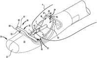
- FIG. 1is a first perspective view of an embodiment of the suturing apparatus having a thread carrier in a retracted condition.
- FIG. 2is a second perspective view of an embodiment of the suturing apparatus having the thread carrier in an extended condition.
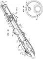
- FIG. 3is a first side elevation view of an embodiment of the suturing apparatus.
- FIG. 4is a top plan view of an embodiment of the suturing apparatus.
- FIG. 5is a second side elevation view of an embodiment of the suturing apparatus.
- FIG. 6is a bottom plan view of an embodiment of the suturing apparatus.
- FIG. 7is an enlarged view of the suturing probe shown in FIG. 1 .
- FIG. 8is an enlarged view of the suturing probe shown FIG. 2 .
- FIG. 9is an enlarged view of the suturing probe shown in FIG. 3 .
- FIG. 10is an enlarged view of the suturing probe shown in FIG. 4 .
- FIG. 11is a cross section view 11 - 11 as shown in FIG. 4 which depicts an embodiment of the suturing probe further including a substrate capture chamber which removably inserts into a substrate capture chamber.
- FIG. 12is a cross section view 12 - 12 as shown in FIG. 4 which depicts an embodiment of the suturing probe having the substrate capture chamber inserted into the substrate capture chamber.
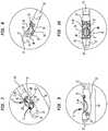
- FIG. 13is an enlarged view of a particular embodiment of a thread carrier and a thread capture chamber showing the position of the thread carrier extended a distance into the thread capture chamber.
- FIG. 14is an enlarged view of a particular embodiment of a thread carrier and a thread capture chamber showing the position of the thread carrier extended a distance into the thread capture chamber to slidingly engage a thread capture assembly.
- FIG. 15is an enlarged view of a particular embodiment of a thread carrier and a thread capture chamber showing the position of the thread carrier extended a distance into the thread capture chamber to align a hook of the thread capture assembly with a notch in the thread carrier.
- FIG. 16is an enlarged view of a particular embodiment of a thread carrier and a thread capture chamber showing the position of the thread carrier slidingly withdrawn from the thread capture assembly to allow the hook to pass through the notch in the thread carrier.
- FIG. 17is a cross section view 17 - 17 of the particular embodiment of the suturing apparatus shown in FIG. 6 .
- FIG. 18is an enlarged view of a portion of the cross section of the suturing probe shown in FIG. 17 .
- FIG. 19is an enlarged perspective view of a portion of the cross section of the suturing apparatus handle shown in FIG. 17 .
- FIG. 20is an enlarged view of cross section 20 - 20 of a tubular member of the suturing apparatus shown in FIG. 4 .
- FIG. 21is an enlarged cross section view of an arrest assembly of the suturing apparatus in a thread carrier first position.
- FIG. 22is an enlarged cross section view of an arrest assembly of the suturing apparatus between a thread carrier first position and a thread carrier second position.
- FIG. 23is an enlarged cross section view of an arrest assembly of the suturing apparatus in a thread carrier second position.
- FIG. 24is a perspective view of a particular embodiment of a suturing apparatus having a thread passing through the thread carrier aperture and disposed in a thread catch.
- FIG. 25is an enlarged perspective view of a thread catch as shown in FIG. 1 .
- FIG. 26is an enlarged perspective view of a thread catch as shown in FIG. 1 .
- FIG. 27is an enlarged side view of a particular embodiment of a thread catch.
- FIG. 28is an enlarged plan view of a particular embodiment of a thread catch.
- FIG. 29is an enlarged view of a particular embodiment of a thread carrier and a thread capture chamber showing the position of thread carrier extended a distance into the thread capture chamber.
- FIG. 30is an enlarged view of a particular embodiment of a thread carrier and a thread capture chamber showing the position of the thread carrier extended a distance into the thread capture chamber to slidingly engage a thread capture assembly.
- FIG. 31is an enlarged view of a particular embodiment of a thread carrier and a thread capture chamber showing the position of the thread carrier extended a distance into the thread capture chamber to align a hook of the thread capture assembly with a notch in the thread carrier.
- FIG. 32is an enlarged view of a particular embodiment of a thread carrier and a thread capture chamber showing the thread carrier being withdrawn from the thread capture chamber allowing the hook of the thread capture assembly to pass through the notch to capture the thread on thread capture assembly.
- FIG. 33Ais a depiction of a particular method of using an embodiment of a suturing apparatus.
- FIG. 33Bis a depiction of a particular method of inserting a suturing probe in a body opening.
- FIG. 33Cis a depiction of a particular method of palpating a substrate toward a substrate capture chamber of the suturing apparatus.
- FIG. 33Dis a depiction of a particular method of operating the suturing apparatus to drive the thread carrier through a substrate.
- FIG. 33Eis a depiction of a particular method of disposing a suture loop in the substrate and removing a suturing probe from a body opening.
- FIG. 34is an illustration of different amounts of substrate purchase obtained by use of different configurations of the suturing apparatus and an embodiment of a substrate reinforcing element sutured adjacent the substrate.
- FIG. 35is a perspective view of an embodiment of a suturing apparatus including a particular embodiment of a substrate reinforcing element.
- FIG. 36is a top plan view of an embodiment of a suturing apparatus including a particular embodiment of a substrate reinforcing element.
- FIG. 37is a cross section view 37 - 37 of the suturing apparatus shown in FIG. 36 .
- FIG. 38is a perspective view of an embodiment of a suturing apparatus including another particular embodiment of a substrate reinforcing element.
- FIG. 39is a top plan view of an embodiment of a suturing apparatus including another particular embodiment of a substrate reinforcing element.
- FIG. 40is a cross section view 40 - 40 as shown in FIG. 39 .
- FIG. 41is a perspective view of an embodiment of a suturing apparatus including another particular embodiment of a substrate reinforcing element.
- FIG. 42is a side view of an embodiment of a suturing apparatus including another particular embodiment of a substrate reinforcing element.
- FIG. 43is a top plan view of an embodiment of a suturing apparatus including another particular embodiment of a substrate reinforcing element.
- a suturing apparatusincluding a substrate capture chamber ( 2 ) and a thread carrier ( 3 ) carrying a thread ( 4 ) which axially moves between a retracted condition ( 5 ) toward an extended condition ( 6 ) in which a thread carrier terminal end ( 7 ) of the thread carrier ( 3 ) passes outside of the substrate capture chamber ( 2 ) into a thread capture chamber ( 8 ) to engage a thread capture assembly ( 9 ) which captures the thread ( 4 ) to generate a thread loop upon return of the thread carrier ( 3 ) toward the retracted condition ( 5 ).
- embodiments of the suturing apparatus ( 1 )can include a suturing probe ( 10 ).
- the suturing probe ( 10 )can outward axially extend from a tubular member ( 11 ) to terminate in a probe tip ( 12 ).
- the suturing probe external surface ( 13 )can, but need not necessarily, be configured as an extension of the external dimensions of the tubular member ( 11 ) allowing the probe tip ( 12 ) to pass through body openings ( 14 ) such as natural body openings or incisions to engage a substrate ( 15 ) (as shown in the illustrative example of FIGS. 33A through 33E ) such as skin, fascia, fat, or muscle.
- substrate ( 15 )include tissue ( 16 ) including human or animal tissue
- this descriptionis not intended to preclude the capture of substrates ( 15 ) other than human or animal tissue, including as illustrative examples, cadaver tissue, simulants of tissue, tissue models, elastomer components, plastic or natural fabrics, or the like.
- the suturing probe ( 10 )can have a generally cylindrical suturing probe external surface ( 13 ) terminating in a hebetated probe tip ( 12 ).
- the suturing probe external surface ( 13 )can include a tapered, beveled, or sloped surface approaching the probe tip ( 12 ) to reduce dimensions at the probe tip ( 12 ).
- a sloped, tapered or inclined probe face ( 17 )can be an advantage in having a sloped, tapered or inclined probe face ( 17 ) as it allows the suturing probe ( 10 ) additional ingress into a substrate ( 15 ) such as animal tissues with a lesser amount of tissue dissection or trauma.
- a substrate capture chamber ( 2 )can be disposed in the suturing probe ( 10 ).
- the substrate capture chamber ( 2 )can include a chamber sidewall ( 18 ) which couples in opposed fixed relation a chamber bottom ( 19 ) a distance from said chamber port ( 20 ) open to the suturing probe external surface ( 13 ).
- the vertical chamber side wall ( 18 )can define a periphery of greater circumference than the periphery of the chamber port ( 20 ).
- the substrate capture chamber ( 2 )can, but need not necessarily, be fluidically coupled to a vacuum source ( 21 ) operable to generate a reduced chamber pressure ( 22 ) in the substrate capture chamber ( 2 ) sufficient to capture, draw, or dispose a substrate ( 15 ) into the substrate capture chamber ( 2 ).
- the suturing probe ( 10 )can include a recessed portion ( 23 ) with the chamber port ( 20 ) open to the recessed portion ( 23 ) of the suturing probe external surface ( 13 ) with the thread carrier ( 3 ) operable to pass within the recessed portion ( 23 ) of the suturing probe external surface ( 13 ) outside of the substrate capture chamber ( 2 ).
- the recessed portion ( 23 ) of the suturing probe external surface ( 13 )can be arcuate (as shown in the illustrative examples of FIGS. 7 through 9 ).
- the arcuate recessed portion ( 23 ) of the suturing probe external surface ( 13 )can, but need not necessarily, be configured to allow a tip of a finger ( 24 ) to apply force to a substrate ( 15 ) to move the substrate toward the substrate capture chamber ( 2 ) (as shown in the illustrative example of FIG. 33C ).
- the recessed portion ( 23 ) of the suturing probe external surface ( 13 )can include a substantially flat arcuate face ( 25 ) in which the chamber port ( 20 ) opens to provide a recessed peripheral margin ( 26 ) about the chamber port ( 20 ).
- a recessed peripheral margin ( 26 )which affords a substantially flat or lessened curvature about the chamber port ( 20 ) in that it can increase the surface area of the suturing probe external surface ( 13 ) contacting a substrate ( 15 ).
- the increased surface area of the suturing probe external surface ( 13 )can afford a substantial advantage in capture of a substrate ( 15 ) in those embodiments in which a reduced chamber pressure ( 22 ) can be generated in the substrate capture chamber ( 2 ) or can decrease movement of the suturing probe ( 10 ) in relation to the substrate ( 15 ) captured in the substrate capture chamber ( 2 ).
- the chamber port ( 20 )can, but need not necessarily, be disposed in a stadium configuration ( 27 ), being a rectangle with semicircles at a pair of opposite sides.
- the substrate capture chamber ( 2 )can, but need not necessarily, have a chamber bottom ( 19 ) in a stadium configuration disposed opposite the chamber port ( 20 ) in stadium configuration connected by a substantially vertical chamber sidewall ( 18 ).
- a substrate capture chamber ( 2 ) of stadium configuration ( 27 )in that an increased amount of substrate ( 15 ) can be disposed in the substrate capture chamber ( 2 ) as compared to a substrate capture chamber ( 2 ) having conventionally slotted or substantially circular substrate capture chamber ( 2 ) and correspondingly the substrate ( 15 ) penetrated by the thread carrier ( 3 ) can dispose a thread entry point ( 28 ) and a thread withdraw point ( 29 ) a greater distance apart (also referred to as the “suture purchase ( 30 )) as compared to conventional slotted or cylindrical suction chambers.
- the suture purchase ( 30 ) generated by use of a stadium configuration ( 27 )can be substantially greater than that obtained using a suction chamber of cylindrical configuration or obtained using a conventional suction chamber of slotted configuration. It may be that the conventional cylindrical configuration draws the substrate into a conical configuration within the conventional cylindrical suction chamber and the conventional needle only penetrates the substrate proximate the apex of the cone. It may be that the conventional slotted suction chamber does not have sufficient volume to dispose the substrate a sufficient distance into the conventional slotted chamber and the conventional needle only penetrates the substrate layers in adjacent relation close to the fold or edges.
- the suturing probecan include a substrate capture chamber insert ( 31 ).
- the substrate capture chamber insert ( 31 )can include a substrate capture chamber insert sidewall ( 32 ) which joins a substrate capture insert bottom ( 33 ) to a substrate capture chamber insert port ( 34 ).
- the substrate capture chamber insert ( 31 )can be removably coupled to the inside of the substrate capture chamber ( 2 ) to alter the configuration or volume of the substrate capture chamber ( 2 ).
- the altered configuration or volume corresponding to the substrate capture chamber insert ( 31 )can accordingly increase or decrease the volume of substrate ( 15 ) captured in the substrate capture chamber ( 2 ) and accordingly adjust the suture purchase ( 30 ) (as shown in the illustrative example of FIG.
- the substrate capture chamber insert ( 31 )can have an insert aperture element ( 35 ) disposed to fluidically couple the internal volume of the substrate capture chamber insert ( 31 ) and substrate capture chamber insert port ( 34 ) with a first longitudinal channel ( 36 ) which couples the substrate capture chamber ( 2 ) to a vacuum port ( 37 ) through which fluid flow ( 38 ) passes to regulate the chamber pressure ( 22 ) within the substrate capture chamber ( 2 ).
- the substrate capture chamber insert ( 31 )can have a substrate capture chamber insert bottom ( 33 ) which between interchangeable embodiments can be disposed at a depth equal to or less than the distance between the substrate capture chamber bottom ( 19 ) and the chamber port ( 20 ).
- the substrate capture chamber insert port ( 34 )can have an open area about equal to or less than the open area defined by the chamber port ( 20 ).
- this illustrative exampleis not intended to preclude other configurations of the substrate capture insert ( 31 ) which can alter only the chamber sidewall ( 18 ), only the chamber port ( 20 ), or only the chamber bottom ( 19 ), or combinations thereof.
- a thread capture assembly ( 9 )can be disposed in the thread capture chamber ( 8 ).
- the thread capture assembly ( 9 )can include at least one resiliently flexible hook member ( 39 A) correspondingly terminating in at least one hook ( 40 A).
- the resiliently flexible hook member ( 39 A)can be coupled to the thread capture chamber internal surface ( 41 ) to dispose the hook ( 40 A) at a location to engage the thread carrier ( 3 ) and flexing the at least one resiliently flexible hook member ( 39 A).
- the thread capture assembly ( 9 )can include a pair of resiliently flexible hook members ( 39 A)( 39 B) each correspondingly terminating in one of a pair of hooks ( 40 A)( 40 B).
- the pair of resiliently flexible hook members ( 39 A)( 39 B)can each be coupled to the thread capture chamber internal surface ( 41 ) to dispose the pair of hooks ( 40 A)( 40 B) a distance apart at locations which allow corresponding engagement on opposed sides of the thread carrier ( 3 ), thereby flexing each of the pair of resiliently flexible hook members ( 39 A)( 39 B) (as shown in the example of FIGS. 13 and 14 ).
- the pair of resiliently flexible hook members ( 39 A)( 39 B)each return toward the unflexed condition correspondingly disengaging each of the pair of hooks ( 40 A)( 40 B) from the thread carrier ( 3 ).
- the thread carrier ( 3 )can further include a notch ( 42 ) disposed a distance axially from the thread carrier aperture element ( 43 ).
- the notch ( 42 )defines a notch passage ( 44 ) between notch passage first and second ends ( 45 )( 46 ) which open on the thread carrier external surface ( 47 ).
- the notch ( 42 )can be disposed angularly across the thread carrier longitudinal axis ( 48 ) of the thread carrier ( 3 ) to dispose the notch passage first end ( 45 ) facing away from the chamber port ( 20 ) proximal the thread carrier terminal end ( 7 ) and the notch passage second end ( 46 ) facing toward the chamber port ( 20 ) distal from the thread carrier terminal end ( 7 ).
- the hook ( 40 A) or the pair of hooks ( 40 A)( 40 B)engage the thread carrier ( 3 ) flexing at least one resiliently flexible hook member ( 39 A) or pair of resiliently flexible hook members ( 39 A)( 39 B) and aligning one of the pair of hooks ( 40 A)( 40 B) with the notch passage second end ( 46 ).
- Resilient flexuremoves the hook ( 40 A) into the notch passage second end ( 46 ).
- the hook ( 40 A)travels through the notch passage ( 44 ) and disengages the thread carrier ( 3 ) by egress from the notch passage first end ( 45 ).
- the thread carrier ( 3 )can be coupled to the drive member first end ( 49 ) and extend axially outward to terminate in a thread carrier terminal end ( 7 ).
- the thread carrier ( 3 )can comprise a slender rod which can, but need not necessarily, taper approaching the thread carrier terminal end ( 7 ).
- the tapercan be sufficient to allow the thread carrier ( 3 ) to pass through a particular type of substrate ( 15 ), and as to particular embodiments, the thread carrier ( 3 ) can taper to a sharp point at the thread carrier terminal end ( 7 ) to pass through a substrate ( 15 ) comprising animal tissue.
- a thread carrier aperture element ( 43 )can be disposed a distance axially from said thread carrier terminal end ( 7 ).
- the thread carrier aperture element ( 43 )defines a thread carrier aperture ( 50 ).
- the thread carrier aperture ( 50 )can have a thread carrier aperture axis ( 51 ) disposed generally orthogonal to the thread carrier longitudinal axis ( 48 ) and generally orthogonal to the plane ( 52 ) longitudinally bisecting the chamber port ( 20 ) (as shown in the cross section of FIG. 18 which longitudinally bisects the chamber port ( 20 ) generally orthogonal to the thread carrier aperture axis ( 51 )).
- embodiments of the suturing apparatus ( 1 )can include a housing ( 53 ).
- the housing ( 53 )can include a handle ( 54 ) and a tubular member ( 11 ) which outwardly axially extends from the handle ( 54 ) terminating in the suturing probe ( 10 ).
- the handle external surface ( 55 )can, but need not necessarily, be configured to be grippingly engaged by the human hand.
- the handle ( 54 )can receive in axial sliding engagement a thread carrier driver ( 56 ).
- the thread carrier driver ( 56 )can include an elongate drive member ( 57 ) having a length disposed between a drive member first end ( 49 ) and a drive member second end ( 58 ).
- the elongate drive member ( 57 )moves axially inside of the handle ( 54 ) in response to a drive member actuator ( 59 ).
- a drive member actuator slot ( 60 )can be disposed in the handle ( 54 ) and the drive member actuator ( 59 ) can be configured to extend through the drive member actuator slot ( 60 ) to present a pressible drive member actuator button ( 61 ) which upon forcible urging generates corresponding axial movement of the elongate drive member ( 57 ) inside of the handle ( 54 ).
- the thread carrier driver ( 56 )can be operated bidirectionally to concurrently reciprocally position the thread carrier terminal end ( 7 ) between a thread carrier first position ( 62 ) which locates the thread carrier terminal end ( 7 ) inside of a second longitudinal channel ( 63 ) which opens to the probe external surface ( 13 ) outside of the substrate capture chamber ( 2 ) and a thread carrier second position ( 64 ) with the thread carrier terminal end ( 7 ) located in the thread capture chamber ( 8 )(as shown in the examples of FIG. 7 thorough 10 ).
- the second longitudinal channel ( 63 )can be fluidically discrete from the first longitudinal channel ( 36 ) coupled to the vacuum source ( 21 ).
- the thread carrier ( 3 ) disposed and reciprocally moved in the second longitudinal channel ( 63 ) from the first position ( 62 ) to the second position ( 64 ) outside of the substrate capture chamber ( 2 )does not require a seal engaging the thread carrier ( 3 ) to maintain reduced chamber pressure ( 22 ) in the substrate capture chamber ( 2 ) generated in the first longitudinal channel ( 36 ) fluidically coupled to the vacuum source ( 21 ).
- the housing ( 53 )can be configured to provide a vacuum port ( 37 ) opening on the handle external surface ( 55 ) (as shown in the examples of FIGS. 1 through 6 and 17 through 19 ).
- the vacuum port ( 37 )can be coupled to a vacuum source ( 21 ) (as shown in the example of FIGS. 1 and 2 ).
- the vacuum source ( 21 )can comprise any of a variety of conventional vacuum or suction pumps.
- the vacuum source ( 21 )can be operated to generate a reduced chamber pressure ( 22 ) in the substrate capture chamber ( 2 ).
- the drive member second end ( 58 )can be coupled to an arrest assembly ( 65 ).
- the arrest assembly ( 65 )can include one or more of an arrest member ( 66 ), a prong receiver ( 67 ), and a prong ( 68 ).
- the arrest member ( 66 )can have a length disposed between an arrest member first end ( 69 ) and an arrest member second end ( 70 ).
- the arrest member first end ( 69 )can be coupled to the thread carrier driver ( 56 ).
- the arrest member second end ( 70 )can have a taper extending toward the arrest member second end ( 70 ). Disposed between the arrest member first and second ends ( 69 )( 70 ) can be a prong receiver ( 67 ).
- the prong receiver ( 67 )can engage the prong ( 68 ) which can be coupled to the internal surface ( 71 ) of the handle ( 54 ).
- the thread carrier driver ( 56 )can be operable to concurrently axially move the thread carrier ( 3 ) and the arrest member ( 66 ).
- the arrest member ( 66 )can flex, allowing the prong ( 68 ) to disengage the prong receiver ( 67 ) when the thread carrier driver ( 56 ) operates to move the thread carrier ( 3 ) toward the thread carrier second position ( 64 ).
- the arrest member ( 66 )can also flex to allow the prong ( 68 ) to traverse along the taper of the arrest member second end ( 70 ) toward the prong receiver ( 67 ), where the prong ( 68 ) can engage the prong receiver ( 67 ) when the thread carrier driver ( 56 ) operates to move the thread carrier ( 3 ) toward the thread carrier first position ( 62 ).
- a thread ( 4 )can be disposed in the thread carrier aperture element ( 43 ).
- the thread slot ( 72 )can be disposed in the suturing probe ( 10 ) adjacent the opening of the second longitudinal channel ( 63 ) in the suturing probe external surface ( 13 ).
- the location of the thread carrier aperture element ( 43 ) disposed in the first position ( 62 )can align with the thread slot ( 72 ) to permit a thread ( 4 ) to be passed through the thread slot ( 72 ) and the thread carrier aperture element ( 43 ).
- a method in a suturing apparatus ( 1 )can include passing a first end ( 73 ) of a thread ( 4 ) through the thread carrier aperture element ( 43 ) disposed on the thread carrier ( 3 ).
- the methodcan further include passing the first end ( 73 ) of the thread ( 4 ) through the thread carrier aperture element ( 43 ) while it is aligned with the thread slot ( 72 ) disposed in the handle ( 54 ).
- the second end ( 74 ) of the thread ( 4 ) (or both ends of the thread ( 4 ))can be retained in a thread catch ( 75 ) disposed on the handle ( 54 ).
- An embodiment of the thread catch ( 75 )can include a thread catch base ( 76 ) including a thread catch slot ( 77 ) configured to catch and retain a thread ( 4 ).
- the thread catch ( 75 )can, but need not necessarily include, one or more friction pads ( 78 ) disposed in opposed relation about the thread catch slot ( 77 ).
- the friction pads ( 78 )can comprise an elastomeric material which increases friction on the thread ( 4 ) when disposed in the thread catch slot ( 77 ).
- the thread catch ( 75 )can include a thread catch base ( 76 ) including a thread catch aperture element ( 80 ).
- the thread catch aperture element ( 80 )can define a thread catch aperture communicating between a distal end of the thread catch ( 75 ) and a proximal end of the thread catch ( 75 ).
- the thread ( 4 )can be passed through the thread catch aperture in a distal to proximal direction.
- a method in a suturing apparatus ( 1 )can include driving a thread carrier ( 3 ) slidingly engaged to the suturing probe ( 10 ) toward the thread capture chamber ( 8 ). Slidingly engaging a thread capture assembly ( 9 ) disposed in the thread capture chamber ( 8 ) with the thread carrier ( 3 ) carrying the thread ( 4 ). Disposing the thread ( 4 ) adjacent at least one resiliently flexible hook member ( 39 A) terminating in a hook ( 40 A). Aligning the hook ( 40 A) with a notch second end ( 46 ) of the notch ( 42 ) disposed in the thread carrier ( 3 ) (as shown in the examples of FIGS. 29 and 30 ).
- a method in a suturing apparatus ( 1 )can include passing a first end ( 73 ) of a thread ( 4 ) through the thread carrier aperture element ( 43 ) disposed on the thread carrier ( 3 ) (as shown in the example of FIG. 33A ). Inserting a suturing probe ( 10 ) into a body opening ( 14 ) of a substrate ( 15 ) (as shown in the example of FIG. 33 B).
- Forcibly urging the substrate ( 15 ) toward a substrate capture chamber ( 2 ) disposed in the suturing probe ( 10 )which as to particular embodiments, includes contacting the substrate ( 15 ) with a finger ( 24 ) or other instrument or device (as shown in the example of FIG. 33C ).
- Capturing the substrate ( 15 ) in the substrate capture chamber ( 2 )which can, but need not necessarily, include generating a reduced chamber pressure ( 22 ) in the substrate capture chamber ( 2 ) by operation of a vacuum source ( 21 ) to draw and retain an amount of the substrate ( 15 ) in the substrate capture chamber ( 2 ).
- Driving a thread carrier ( 3 )slidably engaged in the suturing probe ( 10 ) toward a thread capture chamber ( 8 ).
- the methodscan further include inserting a substrate capture chamber insert ( 31 ) into the substrate capture chamber ( 2 ).
- the methodcan further include pressing a drive member actuator button ( 61 ) extending through the drive member actuator slot ( 60 ) in a handle ( 54 ) of the suturing apparatus ( 1 ).
- the pressingcan generate movement in the thread carrier ( 3 ) in a first direction ( 79 ) toward the thread capture chamber ( 8 ).
- the movement of the thread carrier ( 3 ) in a first direction ( 79 )can pass the thread carrier ( 3 ) through the substrate ( 15 ) outside of the substrate capture chamber ( 2 ) into the thread capture chamber ( 8 ) without compromising the integrity of the reduced chamber pressure ( 22 ) generated by a vacuum source ( 21 ) fluidically coupled to the substrate capture chamber ( 2 ).
- the methodcan further include flexing an arrest assembly ( 65 ), thereby disengaging the prong ( 68 ) from the prong receiver ( 67 ) and advancing the prong ( 68 ) along the taper of the arrest member second end ( 70 ) and to permit the movement of the thread carrier ( 3 ) in the first direction ( 79 ).
- FIG. 34there can be an advantage in varying the configuration or volume of the substrate capture chamber ( 2 ).
- Various configurations and volumes of the substrate capture chamber ( 2 )can occur by utilizing a substrate capture chamber insert ( 31 ) and the option of utilizing a vacuum source ( 21 ) to reduce pressure ( 22 ) in the substrate capture chamber ( 2 ) to correspondingly vary the suture purchase ( 30 ) in the substrate ( 15 , 16 ) depending on the requirements of the application.
- reducing pressure ( 22 ) in the substrate capture chamber ( 2 )can capture an increased amount of substrate ( 15 ) in the substrate capture chamber ( 2 ), thereby increasing the suture purchase ( 30 ).
- the suture purchase ( 30 )can be adjusted by the use of a substrate capture chamber insert ( 31 ) which varies the volume of the substrate capture chamber ( 2 ) available to receive the substrate ( 15 ).
- a substrate capture chamber insert ( 31 )can be utilized without a vacuum source ( 21 ), decreasing the suture purchase ( 30 ) as opposed to an application which utilizes a vacuum source ( 21 ).
- the suture purchase ( 30 )can be increased or decreased depending upon the application.
- the suturing apparatus ( 1 )can further include a substrate reinforcing element ( 80 ) which can, by operation of the suturing apparatus ( 1 ), be disposed under the thread ( 4 )(as shown in the example of FIG. 34 ) to provide mechanical support to the suture purchase ( 30 ) in the substrate ( 15 )(tissue ( 16 )) to prohibit or reduce the possibility of the thread ( 4 ) tearing through the substrate ( 15 )(tissue ( 16 )) by diffusing suturing forces over a greater substrate area ( 83 ) (shown in the example of FIG. 34 in broken line) than contacted by the thread ( 4 )(suture) alone.
- a substrate reinforcing element ( 80 )which can, by operation of the suturing apparatus ( 1 ), be disposed under the thread ( 4 )(as shown in the example of FIG. 34 ) to provide mechanical support to the suture purchase ( 30 ) in the substrate ( 15 )(tissue ( 16 )) to prohibit or reduce the
- the substrate reinforcing element ( 80 )can, but need not necessarily, protect the substrate area ( 83 ) or deliver compositions to the substrate area ( 83 ) such as drugs, antibiotics, hormones, or the like, or combinations thereof.
- the substrate reinforcing element ( 80 )can be produced from a wide variety of solid, porous, woven, or apertured non-woven substrate reinforcing materials, including or consisting of: polytetrafluoroethylene, polypropylene, polyethylene, polyethersulfone, polyurethane, and felt, or combinations thereof.
- the substrate reinforcing element ( 80 )can be produced from a biodegradable material.
- “Biodegradable” for the purposes of this inventionmeans the ability of any biocompatible material to breakdown within the physiological environment of the substrate area ( 83 ) by one or more physical, chemical, or cellular processes at a rate consistent with providing structural reinforcement of the substrate area ( 83 ) or delivering pharmaceuticals at a therapeutic level controllable by selection of a polymer or mixture of polymers (also referred to as polymeric materials), including, but not limited to: poly-4-hydroxybutyrate (P4HB), polylactide polymers (PLA), copolymers of lactic and glycolic acids (PLGA), polylactic acid-polyethylene oxide copolymers, poly( ⁇ -caprolactone-co-L-lactic acid (PCL-LA), glycine/PLA copolymers, PLA copolymers involving polyethylene oxides (PEO), acetylated polyvinyl alcohol (PVA)/polycaprolactone
- embodiments of the substrate reinforcing element ( 80 )can include a body ( 84 ) capable of being penetrated by the thread carrier ( 3 ) when the thread carrier ( 3 ) moves in a first direction ( 79 )(as shown in the examples of FIGS. 36, 39 and 42 ) toward the thread capture chamber ( 8 ) and of releasing the thread carrier ( 3 ) when the thread carrier ( 3 ) moves in a second direction ( 85 ) away from the thread capture chamber ( 8 ) while retaining the thread ( 4 ).
- one or more retaining elements ( 86 )can be coupled to the substrate reinforcing element ( 80 )(as shown in the example of FIG. 38 ).
- Each of the one or more retaining elements ( 86 )can increase the adherence of the substrate reinforcing element ( 80 ) to the substrate ( 15 ).
- Examples of a retaining element ( 86 )can include barbs, projections, hooks, prongs, bristles, spikes, points, spines, or other features the increase adherence of the substrate reinforcing element ( 80 ) to the substrate ( 15 )( 16 ).
- the substrate reinforcing element ( 80 )can include a one-piece body ( 84 ) disposable in the substrate capture chamber ( 2 ) of the suturing apparatus ( 1 ).
- the one-piece body ( 84 )can be formed as or cut from a flexible sheet material have a thickness disposed between a top surface ( 87 ) and a bottom surface ( 88 ).
- the top surface ( 87 ) and the bottom surface ( 88 )can each extend to a peripheral edge ( 89 ).
- the peripheral edge ( 89 )can define a rectangle, square, circle, elongate strip, or other configuration compatible with the substrate suturing application.
- the body ( 84 )can be bowed or folded within the substrate capture chamber ( 2 ) of the suturing apparatus ( 1 )(as shown in the example of FIGS. 36 and 37 ).
- the substrate ( 15 )which can, but need not necessarily, be a tissue ( 16 ), can be captured within the bowed or folded body ( 84 ) of the substrate reinforcing element ( 80 )(as shown in the illustrative example of FIG. 36 ).
- the thread carrier ( 3 )can penetrate the one-piece body ( 84 ) at a first and second puncture points ( 90 )( 91 ) when it moves in a first direction ( 79 ) toward the thread capture chamber ( 8 ).
- the thread capture assembly ( 9 )can capture the thread ( 4 ) as above described.
- the thread carrier ( 3 )can move in a second direction ( 85 ) away from the thread capture chamber ( 8 ) egressing through the first and second puncture points ( 90 )( 91 ) to release the thread carrier ( 3 ) with the thread ( 4 ) retained within the first and second puncture points ( 90 )( 91 ) in the one-piece body ( 84 ) of the substrate reinforcing element ( 80 ) and the substrate ( 15 )( 16 ) (as shown in the example of FIG. 34 ).
- the body ( 84 )can, but need not necessarily, further include one or more aperture elements ( 92 ) whether pre-formed in the body ( 84 ) or formed by the penetration of thread carrier ( 3 ) through the thickness of the body ( 84 ) a first and second puncture points ( 90 )( 91 ).
- Pre-formed aperture elements ( 92 )can be located on the body ( 84 ) bowed or folded within the substrate capture chamber ( 2 ) of the suturing apparatus ( 1 ) to receive the thread carrier ( 4 ) when it moves in a first direction ( 79 ) toward the thread capture chamber ( 8 ).
- the pre-formed aperture elements ( 92 )can be circular apertures or elongate slots or slits which facilitate movement of the body ( 84 ) in relation to the thread carrier ( 4 ) toward the central area of the aperture element ( 92 ).
- the substrate reinforcing element ( 80 )can include a pair of leaves ( 93 )( 94 ) each having a length between leave first and second ends ( 95 )( 96 ).
- the leaf first ends ( 95 )can be secured within the substrate capture chamber ( 2 ) by leaf retaining elements ( 82 ) with the leaf second ends ( 96 ) disposed a distance apart outside of the substrate capture chamber ( 2 ).
- the leaf retaining elements ( 82 )can each comprise a recess disposed in the bottom of the substrate capture chamber ( 2 ).
- the leaf retaining elements ( 82 )can also take the form of flexibly resilient members which outwardly flex to receive and grip the leaf first ends ( 95 ).
- the substrate ( 15 )( 16 )can be captured between the pair of leaves ( 93 )( 94 ) of the substrate reinforcing element ( 80 ) within the substrate capture chamber ( 2 ).
- the thread carrier ( 3 )can penetrate the pair of leaves ( 93 )( 94 ) at a first and second puncture points ( 90 )( 91 ) when it moves in a first direction ( 79 ) toward the thread capture chamber ( 8 ).
- the thread capture assembly ( 9 )can capture the thread ( 4 ) as above described.
- the thread carrier ( 3 )can move in a second direction ( 85 ) away from the thread capture chamber ( 8 ) egressing through the first and second puncture points ( 90 )( 91 ) to release the thread carrier ( 3 ) with the thread ( 4 ) retained within the first and second puncture points ( 90 )( 91 ) in the body ( 84 ) of the substrate reinforcing element ( 80 ).
- One or both of the pair of leaves ( 93 )( 94 )can include an aperture element ( 92 ) as above described.
- the substrate reinforcing element ( 80 )can comprise a tubular member ( 97 ) having a length disposed between a tubular member first end ( 98 ) and a tubular member second end ( 99 ).
- the tubular member ( 97 )can be disposed on or about the thread carrier ( 3 ) whereby movement of the thread carrier ( 3 ) correspondingly generates movement of the tubular member ( 97 ).
- the thread carrier ( 4 )can pass longitudinally through the substrate reinforcing element ( 80 ) to generate a tubular member ( 97 ) having an interior passage ( 100 ).
- the tubular member ( 97 )can, but need not necessarily, have a preformed interior passage ( 100 ) extending between the tubular member first end ( 98 ) and the tubular member second end ( 99 ).
- the interior passage ( 100 )can be formed to provide an interior diameter ( 101 ) which receives the thread carrier ( 3 ) when the thread carrier ( 3 ) moves in a first direction ( 79 ) toward the thread capture chamber ( 8 ).
- the tubular member ( 97 )can move with the thread carrier ( 3 ) in a first direction ( 79 ) to be disposed within the substrate ( 15 ) as the thread carrier ( 3 ) passes into the thread capture chamber ( 8 ).
- the interior passage ( 100 )can release the thread carrier ( 3 ) when the thread carrier ( 3 ) moves in a second direction ( 85 ) away from the thread capture chamber ( 8 ) to locate the tubular member ( 97 ) within the substrate ( 15 )( 16 ) with the thread ( 4 ) disposed in the interior passage ( 100 ).
- a first flange ( 103 )can extend radially outward from the tubular member ( 97 ) proximate the tubular member first end ( 98 ).
- a second flange ( 104 )can extend radially outward from the tubular member ( 97 ) proximate the tubular member second end ( 99 ).
- Each of the first and second flanges ( 103 )( 104 )can comprise annular flanges which extend the interior passage ( 100 ) to communicate with first and second flange ends ( 105 )( 106 ).
- first or second flange ( 103 )( 104 )can be configured as a cone ( 107 ) or truncated cone ( 108 ) with the apex of the cone ( 107 ) or the lesser diameter end ( 109 ) of the truncated cone disposable proximate the thread capture chamber ( 8 ) and the greater diameter end ( 110 ) of the truncated cone ( 108 ) distal the thread capture chamber ( 8 ); however these illustrative examples are not intended to obviate first and second flanges ( 103 )( 104 ) configured generally as a sphere, an ovoid, a cylinder, an inverted truncated cone, or any configuration which radial extends outward of the tubular member ( 97 ) to oppose being released from the substrate ( 15 ) upon movement of the thread carrier ( 3 ) in the second direction ( 85 ).
- the tubular member ( 97 )can shorten and correspondingly radially expand in response to longitudinal compressing forces applied as the thread carrier ( 3 ) enters the thread capture chamber ( 8 ) and the greater diameter tubular member first end ( 98 ) correspondingly contacts the suturing probe external surface ( 13 ) with the tubular member second end ( 99 ) further driven toward the thread capture chamber ( 8 ) by an abutting element ( 111 ) disposed on the thread carrier ( 3 ).
- the tubular member ( 97 )can include a plurality of radially expandable cylindrical elements ( 112 ) which are relatively independent in their ability to expand and to flex relative to one another in a manner associated with expandable stents; however, this illustrative example is not intended to obviate embodiments in which the tubular member ( 97 ) radially expands by deformation of a compressible material included in the tubular member ( 97 ).
- a methodcan include disposing the substrate reinforcing element ( 80 ) (whether as a one piece body ( 84 ) or as a pair of leaves ( 93 )( 94 )) within or adjacent the substrate capture chamber ( 2 ), capturing a substrate ( 15 ) in the substrate capturing chamber ( 2 ), and driving the thread carrier ( 3 ) carrying a thread ( 4 ) toward the thread capture chamber ( 8 ) whereby the thread carrier ( 3 ) carrying the thread ( 4 ) passes through the substrate reinforcing element ( 80 ) and the substrate ( 15 ) outside of the substrate capture chamber ( 2 ).
- the methodcan further include capturing the thread ( 4 ) on a thread capture assembly ( 9 ) within the thread capture chamber ( 8 ) and withdrawing the thread carrier ( 3 ) through the substrate reinforcing element ( 80 ) and the substrate ( 15 ) to dispose the substrate reinforcing element ( 80 ) adjacent the substrate ( 15 ) with the thread ( 4 ) passing through the substrate reinforcing element ( 80 ) and the substrate ( 15 ) outside of the substrate capture chamber ( 2 ).
- a methodcan include disposing the substrate reinforcing element ( 80 ) adjacent the substrate capture chamber ( 2 ) having a tubular member first end ( 98 ) or tubular member second end ( 99 ) adjacent the thread carrier terminal end ( 7 ). The method can further include passing the thread carrier ( 3 ) through the tubular member ( 97 ) between tubular member first and second ends ( 98 )( 99 ) to generate an interior passage ( 100 ). In particular embodiments in which the interior passage ( 100 ) may be pre-formed, the method can include passing the thread carrier ( 3 ) through the interior passage ( 100 ).
- the methodcan further include moving the tubular member ( 97 ) by operation of the thread carrier ( 3 ) in a first direction ( 79 ) toward the thread capture member ( 8 ).
- the methodcan further include passing the tubular member ( 97 ) through the substrate ( 15 ) concurrent with passing the thread carrier ( 3 ) into the thread capture assembly ( 9 ).
- the methodcan further include capturing the thread ( 4 ) on a thread capture assembly ( 8 ) within the thread capture chamber ( 8 ) and withdrawing the thread carrier ( 3 ) through the substrate reinforcing element ( 80 ) and the substrate ( 15 ) to dispose the substrate reinforcing element within the substrate ( 15 ) with the thread ( 4 ) passing through the substrate reinforcing element ( 80 ) and the substrate ( 15 ) outside of the substrate capture chamber ( 2 ).
- the one-piece body ( 84 )can be wholly or partially disposed in the substrate capture chamber ( 2 ) prior to or after capturing a substrate ( 15 ) in the substrate capture chamber ( 2 ).
- the basic concepts of the present inventionmay be embodied in a variety of ways.
- the inventioninvolves numerous and varied embodiments of a mountable carrier and methods for making and using such mountable carrier including the best mode.
- each element of an apparatus or each step of a methodmay be described by an apparatus term or method term. Such terms can be substituted where desired to make explicit the implicitly broad coverage to which this invention is entitled. As but one example, it should be understood that all steps of a method may be disclosed as an action, a means for taking that action, or as an element which causes that action. Similarly, each element of an apparatus may be disclosed as the physical element or the action which that physical element facilitates.
- the term “a” or “an” entityrefers to one or more of that entity unless otherwise limited. As such, the terms “a” or “an”, “one or more” and “at least one” can be used interchangeably herein.
- each of the suturing systems or substrate reinforcing elements herein disclosed and describedii) the related methods disclosed and described, iii) similar, equivalent, and even implicit variations of each of these devices and methods, iv) those alternative embodiments which accomplish each of the functions shown, disclosed, or described, v) those alternative designs and methods which accomplish each of the functions shown as are implicit to accomplish that which is disclosed and described, vi) each feature, component, and step shown as separate and independent inventions, vii) the applications enhanced by the various systems or components disclosed, viii) the resulting products produced by such systems or components, ix) methods and apparatuses substantially as described hereinbefore and with reference to any of the accompanying examples, x) the various combinations and permutations of each of the previous elements disclosed.
Landscapes
- Health & Medical Sciences (AREA)
- Life Sciences & Earth Sciences (AREA)
- Surgery (AREA)
- Heart & Thoracic Surgery (AREA)
- Engineering & Computer Science (AREA)
- Biomedical Technology (AREA)
- Nuclear Medicine, Radiotherapy & Molecular Imaging (AREA)
- Medical Informatics (AREA)
- Molecular Biology (AREA)
- Animal Behavior & Ethology (AREA)
- General Health & Medical Sciences (AREA)
- Public Health (AREA)
- Veterinary Medicine (AREA)
- Surgical Instruments (AREA)
Abstract
Description
Claims (3)
Priority Applications (10)
| Application Number | Priority Date | Filing Date | Title |
|---|---|---|---|
| US15/994,932US11033261B2 (en) | 2018-05-31 | 2018-05-31 | Suture system |
| CN201880095110.7ACN112367930B (en) | 2018-05-31 | 2018-06-13 | Suture system |
| JP2020566288AJP7157178B2 (en) | 2018-05-31 | 2018-06-13 | suture system |
| EP18920964.6AEP3801291A4 (en) | 2018-05-31 | 2018-06-13 | SUTURE SYSTEM |
| PCT/US2018/037406WO2019231478A1 (en) | 2018-05-31 | 2018-06-13 | Suture system |
| CA3101004ACA3101004A1 (en) | 2018-05-31 | 2018-06-13 | Suture system |
| AU2018425461AAU2018425461B2 (en) | 2018-05-31 | 2018-06-13 | Suture system |
| IL278839AIL278839A (en) | 2018-05-31 | 2020-11-19 | Suture system |
| JP2021006906AJP7317057B2 (en) | 2018-05-31 | 2021-01-20 | suture system |
| US17/326,789US12137900B2 (en) | 2018-05-31 | 2021-05-21 | Suture system |
Applications Claiming Priority (1)
| Application Number | Priority Date | Filing Date | Title |
|---|---|---|---|
| US15/994,932US11033261B2 (en) | 2018-05-31 | 2018-05-31 | Suture system |
Related Child Applications (1)
| Application Number | Title | Priority Date | Filing Date |
|---|---|---|---|
| US17/326,789ContinuationUS12137900B2 (en) | 2018-05-31 | 2021-05-21 | Suture system |
Publications (2)
| Publication Number | Publication Date |
|---|---|
| US20190365380A1 US20190365380A1 (en) | 2019-12-05 |
| US11033261B2true US11033261B2 (en) | 2021-06-15 |
Family
ID=68694825
Family Applications (2)
| Application Number | Title | Priority Date | Filing Date |
|---|---|---|---|
| US15/994,932Active2038-08-19US11033261B2 (en) | 2018-05-31 | 2018-05-31 | Suture system |
| US17/326,789Active2038-12-25US12137900B2 (en) | 2018-05-31 | 2021-05-21 | Suture system |
Family Applications After (1)
| Application Number | Title | Priority Date | Filing Date |
|---|---|---|---|
| US17/326,789Active2038-12-25US12137900B2 (en) | 2018-05-31 | 2021-05-21 | Suture system |
Country Status (8)
| Country | Link |
|---|---|
| US (2) | US11033261B2 (en) |
| EP (1) | EP3801291A4 (en) |
| JP (2) | JP7157178B2 (en) |
| CN (1) | CN112367930B (en) |
| AU (1) | AU2018425461B2 (en) |
| CA (1) | CA3101004A1 (en) |
| IL (1) | IL278839A (en) |
| WO (1) | WO2019231478A1 (en) |
Cited By (1)
| Publication number | Priority date | Publication date | Assignee | Title |
|---|---|---|---|---|
| US12137900B2 (en) | 2018-05-31 | 2024-11-12 | Cypris Medical, Inc. | Suture system |
Families Citing this family (3)
| Publication number | Priority date | Publication date | Assignee | Title |
|---|---|---|---|---|
| US12137899B2 (en) | 2020-05-11 | 2024-11-12 | Cypris Medical, Inc. | Multiple suture placement system |
| US12011161B2 (en)* | 2021-01-21 | 2024-06-18 | Ethicon, Inc. | Suture needle adaptors for delivering suture needles through cannulas while simultaneously visualizing the delivery of the suture needles through the cannulas |
| US20240341749A1 (en)* | 2023-04-12 | 2024-10-17 | Cypris Medical, Inc. | Suturing Apparatus Needle Drive |
Citations (75)
| Publication number | Priority date | Publication date | Assignee | Title |
|---|---|---|---|---|
| US3206217A (en) | 1961-11-07 | 1965-09-14 | George A Shepard | Vacuum seal for wire feed |
| US4210148A (en) | 1978-11-03 | 1980-07-01 | Stivala Oscar G | Retention suture system |
| US4268481A (en) | 1979-03-23 | 1981-05-19 | Kommandittiyhtio Finnpipette Osmo A. Suovaniemi | Pipette |
| US4373530A (en) | 1980-04-04 | 1983-02-15 | Lisa Ann Kilejian | Surgical stitching instrument |
| US4823794A (en) | 1982-07-12 | 1989-04-25 | Pierce William S | Surgical pledget |
| US4841888A (en) | 1984-09-11 | 1989-06-27 | Mills Timothy N | Sewing machine |
| US4950283A (en) | 1988-12-29 | 1990-08-21 | John Lezdey | Surgical clip |
| US5080663A (en) | 1990-09-26 | 1992-01-14 | Univerity College London | Sewing device |
| US5507754A (en) | 1993-08-20 | 1996-04-16 | United States Surgical Corporation | Apparatus and method for applying and adjusting an anchoring device |
| US5525302A (en) | 1991-02-01 | 1996-06-11 | Astle; Thomas W. | Method and device for simultaneously transferring plural samples |
| US5549617A (en) | 1993-08-20 | 1996-08-27 | United States Surgical Corporation | Apparatus and method for applying and adjusting an anchoring device |
| US5562686A (en) | 1995-04-19 | 1996-10-08 | United States Surgical Corporation | Apparaus and method for suturing body tissue |
| US5766186A (en) | 1996-12-03 | 1998-06-16 | Simon Fraser University | Suturing device |
| US5792163A (en) | 1996-01-03 | 1998-08-11 | Hitzig; Gary | Linear punch |
| US5792153A (en)* | 1994-03-23 | 1998-08-11 | University College London | Sewing device |
| US5797927A (en) | 1995-09-22 | 1998-08-25 | Yoon; Inbae | Combined tissue clamping and suturing instrument |
| US5908426A (en) | 1997-04-24 | 1999-06-01 | Pierce; Javin | Suture needle manipulator |
| US5984932A (en) | 1996-11-27 | 1999-11-16 | Yoon; Inbae | Suturing instrument with one or more spreadable needle holders mounted for arcuate movement |
| US6048351A (en) | 1992-09-04 | 2000-04-11 | Scimed Life Systems, Inc. | Transvaginal suturing system |
| US6059800A (en)* | 1997-09-10 | 2000-05-09 | Applied Medical Resources Corporation | Suturing apparatus and method |
| US6077276A (en) | 1997-10-29 | 2000-06-20 | X-Site L.L.C. | Device and method for suturing blood vessels and the like |
| US6155989A (en) | 1999-06-25 | 2000-12-05 | The United States Of America As Represented By The United States Department Of Energy | Vacuum enhanced cutaneous biopsy instrument |
| US20020119177A1 (en) | 2000-12-21 | 2002-08-29 | Bowman Steven M. | Reinforced foam implants with enhanced integrity for soft tissue repair and regeneration |
| US6464707B1 (en) | 1999-04-01 | 2002-10-15 | David B. Bjerken | Vacuum-assisted remote suture placement system |
| US6533796B1 (en) | 2000-10-11 | 2003-03-18 | Lsi Solutions, Inc. | Loader for surgical suturing instrument |
| US20030208209A1 (en) | 2000-03-03 | 2003-11-06 | Gambale Richard A. | Endoscopic tissue apposition device with multiple suction ports |
| US20040015177A1 (en) | 2002-07-22 | 2004-01-22 | Scimed Life Systems, Inc. | Placing sutures |
| US20040034371A1 (en) | 2001-05-18 | 2004-02-19 | Glen Lehman | Method of promoting tissue adhesion |
| WO2004062466A2 (en) | 2003-01-03 | 2004-07-29 | Eye Plastics Surgery, Ltd. | Surgical instrument for endoscopic suturing of deep subcutaneous tissue |
| US20040236353A1 (en) | 2002-06-26 | 2004-11-25 | Opus Medical, Inc. | Suture capture device |
| US6955643B2 (en) | 2002-06-12 | 2005-10-18 | Boston Scientific Scimed, Inc. | Endoscopic suture instrument |
| US20050251153A1 (en)* | 2004-04-07 | 2005-11-10 | Pankaj Jay Pasricha | Ligature and suture device for medical application, ligature and suture system for medical application, and ligaturing and suturing method for medical application |
| US6997931B2 (en) | 2001-02-02 | 2006-02-14 | Lsi Solutions, Inc. | System for endoscopic suturing |
| US20060036232A1 (en) | 2002-10-04 | 2006-02-16 | Tyco Healthcare Group Lp | Surgical suturing apparatus with measurement structure |
| US20060085016A1 (en) | 2004-10-15 | 2006-04-20 | Sorin Eremia | Suture instrument and method of suturing in cosmetic surgery |
| US7033370B2 (en) | 1992-09-04 | 2006-04-25 | Boston Scientific Scimed, Inc. | Suturing instruments and methods of use |
| US7063710B2 (en) | 2002-04-15 | 2006-06-20 | Nipro Corporation | Intracardiac suture device |
| US7175636B2 (en) | 2001-08-31 | 2007-02-13 | Tetsuya Yamamoto | Endoscopic suturing instrument |
| US7220266B2 (en) | 2000-05-19 | 2007-05-22 | C. R. Bard, Inc. | Tissue capturing and suturing device and method |
| US20080147096A1 (en) | 2002-09-06 | 2008-06-19 | C.R. Bard Inc. | Integrated endoscope and accessory treament device |
| US20090018580A1 (en) | 2007-07-13 | 2009-01-15 | Wulc Allan E | Surgical Method and Apparatus |
| US7517356B2 (en) | 2002-04-16 | 2009-04-14 | Tyco Healthcare Group Lp | Surgical stapler and method |
| US20100016868A1 (en) | 2003-07-07 | 2010-01-21 | Kim Andrew C | Hydrodynamic Suture Passer |
| US20100137888A1 (en) | 2003-01-03 | 2010-06-03 | Eye Plastic Surgery, Ltd. | Surgical Instrument for Endoscopic Suturing of Deep Subcutaneous Tissue |
| US7731727B2 (en) | 2006-04-26 | 2010-06-08 | Lsi Solutions, Inc. | Medical instrument to place a pursestring suture, open a hole and pass a guidewire |
| US7763036B2 (en) | 2006-03-31 | 2010-07-27 | Ethicon Endo-Surgery, Inc. | Endoscopic instrument with secondary vacuum source |
| US20100249498A1 (en) | 2009-03-24 | 2010-09-30 | Tyco Healthcare Group Lp | Endoscopic Apparatus for Manipulating Tissue |
| US7833236B2 (en) | 2005-06-13 | 2010-11-16 | Ethicon Endo-Surgery, Inc. | Surgical suturing apparatus with collapsible vacuum chamber |
| US7846169B2 (en) | 2005-06-13 | 2010-12-07 | Ethicon Endo-Surgery, Inc. | Adjustable vacuum chamber for a surgical suturing apparatus |
| US20110082347A1 (en) | 2009-10-07 | 2011-04-07 | Tyco Healthcare Group Lp | Spring jaw retraction device |
| US8075573B2 (en) | 2003-05-16 | 2011-12-13 | C.R. Bard, Inc. | Single intubation, multi-stitch endoscopic suturing system |
| US20120029536A1 (en) | 2008-09-29 | 2012-02-02 | Dicesare Paul C | Endoscopic suturing device |
| US8177797B2 (en) | 2003-07-17 | 2012-05-15 | Gunze Limited | Suture reinforement material for automatic suturing device |
| US8177794B2 (en) | 2006-10-05 | 2012-05-15 | Tyco Healthcare Group Lp | Flexible endoscopic stitching devices |
| US8226665B2 (en) | 2008-04-04 | 2012-07-24 | Tyco Healthcare Group Lp | Ultrasonic needle driver |
| US20120215235A1 (en) | 2004-08-27 | 2012-08-23 | Davol, Inc. (a C.R. Bard Company) | Endoscopic tissue apposition device and method of use |
| US8286847B2 (en) | 2005-10-14 | 2012-10-16 | Tyco Healthcare Group Lp | Apparatus for laparoscopic or endoscopic procedures |
| US8292886B2 (en) | 2009-10-06 | 2012-10-23 | Tyco Healthcare Group Lp | Apparatus, system, and method for performing an electrosurgical procedure |
| US8313509B2 (en) | 2010-01-19 | 2012-11-20 | Covidien Lp | Suture and retainer assembly and SULU |
| US8403837B2 (en) | 2009-08-13 | 2013-03-26 | Covidien Lp | Deployable jaws retraction device |
| US8465499B2 (en) | 2002-05-08 | 2013-06-18 | Olympus Corporation | Apparatus for ligating/suturing living tissues and system for resecting/suturing living tissues |
| US8475453B2 (en) | 2006-10-06 | 2013-07-02 | Covidien Lp | Endoscopic vessel sealer and divider having a flexible articulating shaft |
| US8490851B2 (en) | 2008-01-15 | 2013-07-23 | Covidien Lp | Surgical stapling apparatus |
| US20140012292A1 (en) | 2010-09-10 | 2014-01-09 | Pivot Medical, Inc. | Method and apparatus for passing suture through tissue |
| US8628545B2 (en) | 2008-06-13 | 2014-01-14 | Covidien Lp | Endoscopic stitching devices |
| US8641729B2 (en) | 2005-07-13 | 2014-02-04 | Creighton University | Systems and techniques for minimally invasive gastrointestinal procedures |
| US20140114309A1 (en) | 2012-10-24 | 2014-04-24 | Covidien Lp | Electrosurgical instrument including an adhesive applicator assembly |
| US8721640B2 (en) | 2006-10-06 | 2014-05-13 | Covidien Lp | Endoscopic vessel sealer and divider having a flexible articulating shaft |
| US20140163375A1 (en) | 2011-08-12 | 2014-06-12 | Jointvue, Llc | 3-D Ultrasound Imaging Device and Methods |
| US20140371760A1 (en) | 2013-06-14 | 2014-12-18 | Covidien Lp | Specimen Retrieval Device Including an Integrated Sliding Grasper |
| US8968340B2 (en) | 2011-02-23 | 2015-03-03 | Covidien Lp | Single actuating jaw flexible endolumenal stitching device |
| US8968339B2 (en) | 2010-12-10 | 2015-03-03 | Covidien Lp | Suturing device with deployable needle |
| US9326770B2 (en) | 2006-01-31 | 2016-05-03 | Ethicon Endo-Surgery, Llc | Surgical instrument |
| US20160338691A1 (en) | 2015-05-19 | 2016-11-24 | Arthrex, Inc. | Suture passer and method of tissue repair |
| US10390818B2 (en) | 2015-08-19 | 2019-08-27 | Lsi Solutions, Inc. | Ferrule for use with a minimally invasive surgical suturing device |
Family Cites Families (35)
| Publication number | Priority date | Publication date | Assignee | Title |
|---|---|---|---|---|
| US5540704A (en) | 1992-09-04 | 1996-07-30 | Laurus Medical Corporation | Endoscopic suture system |
| US5496332A (en)* | 1994-10-20 | 1996-03-05 | Cordis Corporation | Wound closure apparatus and method for its use |
| US6620166B1 (en)* | 1998-01-09 | 2003-09-16 | Ethicon, Inc. | Suture buttress system |
| US6443963B1 (en)* | 2000-07-26 | 2002-09-03 | Orthopaedic Biosystems, Ltd. | Apparatus and method for repairing or reattaching soft tissue |
| US9060844B2 (en)* | 2002-11-01 | 2015-06-23 | Valentx, Inc. | Apparatus and methods for treatment of morbid obesity |
| US20040249367A1 (en)* | 2003-01-15 | 2004-12-09 | Usgi Medical Corp. | Endoluminal tool deployment system |
| US7381210B2 (en) | 2003-03-14 | 2008-06-03 | Edwards Lifesciences Corporation | Mitral valve repair system and method for use |
| US20080154303A1 (en)* | 2006-12-21 | 2008-06-26 | Cardiva Medical, Inc. | Hemostasis-enhancing device and method for its use |
| US20050251208A1 (en)* | 2004-05-07 | 2005-11-10 | Usgi Medical Inc. | Linear anchors for anchoring to tissue |
| EP3326543B1 (en) | 2004-08-24 | 2019-07-24 | DePuy Mitek, LLC | Expandable needle suture apparatus and associated handle assembly with rotational suture manipulation system |
| US20070005068A1 (en)* | 2005-02-07 | 2007-01-04 | Sklar Joseph H | Knotless suture anchor |
| US20070118207A1 (en)* | 2005-05-04 | 2007-05-24 | Aga Medical Corporation | System for controlled delivery of stents and grafts |
| US20060282088A1 (en)* | 2005-06-08 | 2006-12-14 | Ryan Timothy J | Apparatus and methods for delivering sutures |
| JP2012521222A (en)* | 2009-03-19 | 2012-09-13 | ミリピード リミテッド ライアビリティー カンパニー | Reconstruction of cardiac features |
| US20110245846A1 (en)* | 2010-02-24 | 2011-10-06 | Usgi Medical, Inc. | Endoscopic tissue anchor deployment devices and methods |
| EP3305209B1 (en)* | 2010-06-09 | 2025-01-08 | C.R. Bard Inc. | Instruments for delivering transfascial sutures and transfascial suture assemblies. |
| US8926640B2 (en) | 2010-07-13 | 2015-01-06 | Lsi Solutions, Inc. | Method and apparatus for closing an opening in thick, moving tissue |
| US20170020510A1 (en)* | 2012-02-29 | 2017-01-26 | Marker Medical, Llc | Suture passing systems and methods |
| US9241707B2 (en) | 2012-05-31 | 2016-01-26 | Abbott Cardiovascular Systems, Inc. | Systems, methods, and devices for closing holes in body lumens |
| JP6270847B2 (en)* | 2012-09-02 | 2018-01-31 | サテュリックス リミテッドSaturix Ltd. | Suture device |
| WO2014055767A1 (en)* | 2012-10-04 | 2014-04-10 | Ziptek L.L.C. | Surgical suture system, tissue restraint/suture capture and tissue anchor |
| AU2014223627A1 (en)* | 2013-02-26 | 2015-09-17 | Smith & Nephew, Inc. | Flexible deformable suture anchor |
| AU2014342300A1 (en)* | 2013-10-29 | 2016-05-19 | Entourage Medical Technologies, Inc. | System for providing surgical access |
| WO2015137873A1 (en)* | 2014-03-14 | 2015-09-17 | I Support Pte. Ltd. | A system for cosmetic enhancement |
| US10736624B2 (en)* | 2014-05-19 | 2020-08-11 | Lsi Solutions, Inc | Minimally invasive surgical suturing device for papillary muscles and methods thereof |
| JP3195956U (en)* | 2014-12-02 | 2015-02-12 | 博之 中嶋 | Suture with tissue reinforcement |
| CN107529943B (en)* | 2015-01-23 | 2019-11-12 | 波士顿科学国际有限公司 | Balloon catheter suturing system with pledget, method, and apparatus |
| WO2016187406A1 (en)* | 2015-05-19 | 2016-11-24 | Lsi Solutions, Inc. | Minimally invasive surgical suturing device for papillary muscles and methods thereof |
| US10639028B2 (en) | 2015-10-29 | 2020-05-05 | Apollo Endosurgery Us, Inc. | Endoscopic suture loop anchors and methods |
| US20170281182A1 (en)* | 2016-04-01 | 2017-10-05 | Ethicon, Inc. | Anastomotic Stapling Reinforcing Buttress and Methods of Deployment |
| US10390814B2 (en)* | 2016-04-20 | 2019-08-27 | Medos International Sarl | Meniscal repair devices, systems, and methods |
| CN109982653A (en) | 2016-09-20 | 2019-07-05 | 外科创新联合有限公司 | For promoting or constraining the device and method of physical feeling |
| US11213389B2 (en) | 2016-10-17 | 2022-01-04 | Lsi Solutions, Inc. | Prosthetic suturing device and methods thereof |
| US10660637B2 (en) | 2018-04-06 | 2020-05-26 | Cypris Medical, Inc. | Suturing system |
| US11033261B2 (en) | 2018-05-31 | 2021-06-15 | Cypris Medical, Inc. | Suture system |
- 2018
- 2018-05-31USUS15/994,932patent/US11033261B2/enactiveActive
- 2018-06-13JPJP2020566288Apatent/JP7157178B2/enactiveActive
- 2018-06-13EPEP18920964.6Apatent/EP3801291A4/ennot_activeWithdrawn
- 2018-06-13CNCN201880095110.7Apatent/CN112367930B/enactiveActive
- 2018-06-13WOPCT/US2018/037406patent/WO2019231478A1/ennot_activeCeased
- 2018-06-13CACA3101004Apatent/CA3101004A1/enactivePending
- 2018-06-13AUAU2018425461Apatent/AU2018425461B2/enactiveActive
- 2020
- 2020-11-19ILIL278839Apatent/IL278839A/enunknown
- 2021
- 2021-01-20JPJP2021006906Apatent/JP7317057B2/enactiveActive
- 2021-05-21USUS17/326,789patent/US12137900B2/enactiveActive
Patent Citations (106)
| Publication number | Priority date | Publication date | Assignee | Title |
|---|---|---|---|---|
| US3206217A (en) | 1961-11-07 | 1965-09-14 | George A Shepard | Vacuum seal for wire feed |
| US4210148A (en) | 1978-11-03 | 1980-07-01 | Stivala Oscar G | Retention suture system |
| US4268481A (en) | 1979-03-23 | 1981-05-19 | Kommandittiyhtio Finnpipette Osmo A. Suovaniemi | Pipette |
| US4373530A (en) | 1980-04-04 | 1983-02-15 | Lisa Ann Kilejian | Surgical stitching instrument |
| US4823794A (en) | 1982-07-12 | 1989-04-25 | Pierce William S | Surgical pledget |
| US4841888A (en) | 1984-09-11 | 1989-06-27 | Mills Timothy N | Sewing machine |
| US4950283A (en) | 1988-12-29 | 1990-08-21 | John Lezdey | Surgical clip |
| US5080663A (en) | 1990-09-26 | 1992-01-14 | Univerity College London | Sewing device |
| US5525302A (en) | 1991-02-01 | 1996-06-11 | Astle; Thomas W. | Method and device for simultaneously transferring plural samples |
| US6346111B1 (en) | 1992-09-04 | 2002-02-12 | Scimed Life Systems, Inc. | Suturing instruments and methods of use |
| US7060077B2 (en) | 1992-09-04 | 2006-06-13 | Boston Scientific Scimed, Inc. | Suturing instruments and methods of use |
| US7033370B2 (en) | 1992-09-04 | 2006-04-25 | Boston Scientific Scimed, Inc. | Suturing instruments and methods of use |
| US6048351A (en) | 1992-09-04 | 2000-04-11 | Scimed Life Systems, Inc. | Transvaginal suturing system |
| US5549617A (en) | 1993-08-20 | 1996-08-27 | United States Surgical Corporation | Apparatus and method for applying and adjusting an anchoring device |
| US5507754A (en) | 1993-08-20 | 1996-04-16 | United States Surgical Corporation | Apparatus and method for applying and adjusting an anchoring device |
| US5792153A (en)* | 1994-03-23 | 1998-08-11 | University College London | Sewing device |
| US5562686A (en) | 1995-04-19 | 1996-10-08 | United States Surgical Corporation | Apparaus and method for suturing body tissue |
| US5797927A (en) | 1995-09-22 | 1998-08-25 | Yoon; Inbae | Combined tissue clamping and suturing instrument |
| US5792163A (en) | 1996-01-03 | 1998-08-11 | Hitzig; Gary | Linear punch |
| US5984932A (en) | 1996-11-27 | 1999-11-16 | Yoon; Inbae | Suturing instrument with one or more spreadable needle holders mounted for arcuate movement |
| US5766186A (en) | 1996-12-03 | 1998-06-16 | Simon Fraser University | Suturing device |
| US5908426A (en) | 1997-04-24 | 1999-06-01 | Pierce; Javin | Suture needle manipulator |
| US6059800A (en)* | 1997-09-10 | 2000-05-09 | Applied Medical Resources Corporation | Suturing apparatus and method |
| US6077276A (en) | 1997-10-29 | 2000-06-20 | X-Site L.L.C. | Device and method for suturing blood vessels and the like |
| US6464707B1 (en) | 1999-04-01 | 2002-10-15 | David B. Bjerken | Vacuum-assisted remote suture placement system |
| US6155989A (en) | 1999-06-25 | 2000-12-05 | The United States Of America As Represented By The United States Department Of Energy | Vacuum enhanced cutaneous biopsy instrument |
| US8100920B2 (en) | 2000-03-03 | 2012-01-24 | C.R. Bard, Inc. | Endoscopic tissue apposition device with multiple suction ports |
| US20030208209A1 (en) | 2000-03-03 | 2003-11-06 | Gambale Richard A. | Endoscopic tissue apposition device with multiple suction ports |
| US7399304B2 (en) | 2000-03-03 | 2008-07-15 | C.R. Bard, Inc. | Endoscopic tissue apposition device with multiple suction ports |
| US7951157B2 (en) | 2000-05-19 | 2011-05-31 | C.R. Bard, Inc. | Tissue capturing and suturing device and method |
| US7220266B2 (en) | 2000-05-19 | 2007-05-22 | C. R. Bard, Inc. | Tissue capturing and suturing device and method |
| US6533796B1 (en) | 2000-10-11 | 2003-03-18 | Lsi Solutions, Inc. | Loader for surgical suturing instrument |
| US20020119177A1 (en) | 2000-12-21 | 2002-08-29 | Bowman Steven M. | Reinforced foam implants with enhanced integrity for soft tissue repair and regeneration |
| US6997931B2 (en) | 2001-02-02 | 2006-02-14 | Lsi Solutions, Inc. | System for endoscopic suturing |
| US20040034371A1 (en) | 2001-05-18 | 2004-02-19 | Glen Lehman | Method of promoting tissue adhesion |
| US7175636B2 (en) | 2001-08-31 | 2007-02-13 | Tetsuya Yamamoto | Endoscopic suturing instrument |
| US7063710B2 (en) | 2002-04-15 | 2006-06-20 | Nipro Corporation | Intracardiac suture device |
| US8413869B2 (en) | 2002-04-16 | 2013-04-09 | Covidien Lp | Surgical stapler and method |
| US7517356B2 (en) | 2002-04-16 | 2009-04-14 | Tyco Healthcare Group Lp | Surgical stapler and method |
| US8465499B2 (en) | 2002-05-08 | 2013-06-18 | Olympus Corporation | Apparatus for ligating/suturing living tissues and system for resecting/suturing living tissues |
| US7442198B2 (en) | 2002-06-12 | 2008-10-28 | Boston Scientific Scimed, Inc. | Suturing instrument with multi-load cartridge |
| US8257369B2 (en) | 2002-06-12 | 2012-09-04 | Boston Scientific Scimed, Inc. | Suturing instrument with pivotable distal portion |
| US6955643B2 (en) | 2002-06-12 | 2005-10-18 | Boston Scientific Scimed, Inc. | Endoscopic suture instrument |
| US20040236353A1 (en) | 2002-06-26 | 2004-11-25 | Opus Medical, Inc. | Suture capture device |
| US8906041B2 (en) | 2002-07-22 | 2014-12-09 | Boston Scientific Scimed, Inc. | Placing sutures |
| US6936054B2 (en) | 2002-07-22 | 2005-08-30 | Boston Scientific Scimed, Inc. | Placing sutures |
| US9504465B2 (en) | 2002-07-22 | 2016-11-29 | Boston Scientific Scimed, Inc. | Placing sutures |
| US20040015177A1 (en) | 2002-07-22 | 2004-01-22 | Scimed Life Systems, Inc. | Placing sutures |
| US8057386B2 (en) | 2002-09-06 | 2011-11-15 | C.R. Bard, Inc. | Integrated endoscope and accessory treatment device |
| US20080147096A1 (en) | 2002-09-06 | 2008-06-19 | C.R. Bard Inc. | Integrated endoscope and accessory treament device |
| US8206284B2 (en) | 2002-09-06 | 2012-06-26 | C.R. Bard, Inc. | Integrated endoscope and accessory treatment device |
| US20060036232A1 (en) | 2002-10-04 | 2006-02-16 | Tyco Healthcare Group Lp | Surgical suturing apparatus with measurement structure |
| US20100137888A1 (en) | 2003-01-03 | 2010-06-03 | Eye Plastic Surgery, Ltd. | Surgical Instrument for Endoscopic Suturing of Deep Subcutaneous Tissue |
| US7060079B2 (en) | 2003-01-03 | 2006-06-13 | Eye Plastic Surgery, Ltd. | Surgical instrument for endoscopic suturing of deep subcutaneous tissue |
| WO2004062466A2 (en) | 2003-01-03 | 2004-07-29 | Eye Plastics Surgery, Ltd. | Surgical instrument for endoscopic suturing of deep subcutaneous tissue |
| US7780684B2 (en) | 2003-01-03 | 2010-08-24 | Allan E. Wulc | Surgical instrument for endoscopic suturing of deep subcutaneous tissue |
| US8075573B2 (en) | 2003-05-16 | 2011-12-13 | C.R. Bard, Inc. | Single intubation, multi-stitch endoscopic suturing system |
| US20100016868A1 (en) | 2003-07-07 | 2010-01-21 | Kim Andrew C | Hydrodynamic Suture Passer |
| US8177797B2 (en) | 2003-07-17 | 2012-05-15 | Gunze Limited | Suture reinforement material for automatic suturing device |
| US20050251153A1 (en)* | 2004-04-07 | 2005-11-10 | Pankaj Jay Pasricha | Ligature and suture device for medical application, ligature and suture system for medical application, and ligaturing and suturing method for medical application |
| US9149270B2 (en) | 2004-08-27 | 2015-10-06 | Davol, Inc. (a C.R. Bard Company) | Endoscopic tissue apposition device and method of use |
| US20120215235A1 (en) | 2004-08-27 | 2012-08-23 | Davol, Inc. (a C.R. Bard Company) | Endoscopic tissue apposition device and method of use |
| US20060085016A1 (en) | 2004-10-15 | 2006-04-20 | Sorin Eremia | Suture instrument and method of suturing in cosmetic surgery |
| US7846169B2 (en) | 2005-06-13 | 2010-12-07 | Ethicon Endo-Surgery, Inc. | Adjustable vacuum chamber for a surgical suturing apparatus |
| US7833236B2 (en) | 2005-06-13 | 2010-11-16 | Ethicon Endo-Surgery, Inc. | Surgical suturing apparatus with collapsible vacuum chamber |
| US8641729B2 (en) | 2005-07-13 | 2014-02-04 | Creighton University | Systems and techniques for minimally invasive gastrointestinal procedures |
| US8286847B2 (en) | 2005-10-14 | 2012-10-16 | Tyco Healthcare Group Lp | Apparatus for laparoscopic or endoscopic procedures |
| US9326770B2 (en) | 2006-01-31 | 2016-05-03 | Ethicon Endo-Surgery, Llc | Surgical instrument |
| US7763036B2 (en) | 2006-03-31 | 2010-07-27 | Ethicon Endo-Surgery, Inc. | Endoscopic instrument with secondary vacuum source |
| US7731727B2 (en) | 2006-04-26 | 2010-06-08 | Lsi Solutions, Inc. | Medical instrument to place a pursestring suture, open a hole and pass a guidewire |
| US8636752B2 (en) | 2006-10-05 | 2014-01-28 | Covidien Lp | Flexible endoscopic stitching devices |
| US8246637B2 (en) | 2006-10-05 | 2012-08-21 | Tyco Healthcare Group Lp | Flexible endoscopic stitching devices |
| US8177794B2 (en) | 2006-10-05 | 2012-05-15 | Tyco Healthcare Group Lp | Flexible endoscopic stitching devices |
| US8506581B2 (en) | 2006-10-05 | 2013-08-13 | Covidien Lp | Flexible endoscopic stitching devices |
| US8337515B2 (en) | 2006-10-05 | 2012-12-25 | Covidien Lp | Flexible endoscopic stitching devices |
| US9113860B2 (en) | 2006-10-05 | 2015-08-25 | Covidien Lp | Flexible endoscopic stitching devices |
| US8372090B2 (en) | 2006-10-05 | 2013-02-12 | Covidien Lp | Flexible endoscopic stitching devices |
| US8968342B2 (en) | 2006-10-05 | 2015-03-03 | Covidien Lp | Flexible endoscopic stitching devices |
| US8292905B2 (en) | 2006-10-05 | 2012-10-23 | Tyco Healthcare Group Lp | Flexible endoscopic stitching devices |
| US8292906B2 (en) | 2006-10-05 | 2012-10-23 | Tyco Healthcare Group Lp | Flexible endoscopic stitching devices |
| US8496674B2 (en) | 2006-10-05 | 2013-07-30 | Covidien Lp | Flexible endoscopic stitching devices |
| US8747424B2 (en) | 2006-10-05 | 2014-06-10 | Covidien Lp | Flexible endoscopic stitching devices |
| US8475453B2 (en) | 2006-10-06 | 2013-07-02 | Covidien Lp | Endoscopic vessel sealer and divider having a flexible articulating shaft |
| US9204924B2 (en) | 2006-10-06 | 2015-12-08 | Covidien Lp | Endoscopic vessel sealer and divider having a flexible articulating shaft |
| US8721640B2 (en) | 2006-10-06 | 2014-05-13 | Covidien Lp | Endoscopic vessel sealer and divider having a flexible articulating shaft |
| US20090018580A1 (en) | 2007-07-13 | 2009-01-15 | Wulc Allan E | Surgical Method and Apparatus |
| US8490851B2 (en) | 2008-01-15 | 2013-07-23 | Covidien Lp | Surgical stapling apparatus |
| US8226665B2 (en) | 2008-04-04 | 2012-07-24 | Tyco Healthcare Group Lp | Ultrasonic needle driver |
| US8628545B2 (en) | 2008-06-13 | 2014-01-14 | Covidien Lp | Endoscopic stitching devices |
| US8882785B2 (en) | 2008-09-29 | 2014-11-11 | Paul C. DiCesare | Endoscopic suturing device |
| US20120029536A1 (en) | 2008-09-29 | 2012-02-02 | Dicesare Paul C | Endoscopic suturing device |
| US20100249498A1 (en) | 2009-03-24 | 2010-09-30 | Tyco Healthcare Group Lp | Endoscopic Apparatus for Manipulating Tissue |
| US8403837B2 (en) | 2009-08-13 | 2013-03-26 | Covidien Lp | Deployable jaws retraction device |
| US20130172685A1 (en) | 2009-08-13 | 2013-07-04 | Covidien Lp | Deployable jaws retraction device |
| US8292886B2 (en) | 2009-10-06 | 2012-10-23 | Tyco Healthcare Group Lp | Apparatus, system, and method for performing an electrosurgical procedure |
| US20130035688A1 (en) | 2009-10-06 | 2013-02-07 | Tyco Healthcare Group Lp | Apparatus, System, and Method for Performing an Electrosurgical Procedure |
| US20110082347A1 (en) | 2009-10-07 | 2011-04-07 | Tyco Healthcare Group Lp | Spring jaw retraction device |
| US8313509B2 (en) | 2010-01-19 | 2012-11-20 | Covidien Lp | Suture and retainer assembly and SULU |
| US20140012292A1 (en) | 2010-09-10 | 2014-01-09 | Pivot Medical, Inc. | Method and apparatus for passing suture through tissue |
| US8968339B2 (en) | 2010-12-10 | 2015-03-03 | Covidien Lp | Suturing device with deployable needle |
| US8968340B2 (en) | 2011-02-23 | 2015-03-03 | Covidien Lp | Single actuating jaw flexible endolumenal stitching device |
| US20140163375A1 (en) | 2011-08-12 | 2014-06-12 | Jointvue, Llc | 3-D Ultrasound Imaging Device and Methods |
| US20140114309A1 (en) | 2012-10-24 | 2014-04-24 | Covidien Lp | Electrosurgical instrument including an adhesive applicator assembly |
| US20140371760A1 (en) | 2013-06-14 | 2014-12-18 | Covidien Lp | Specimen Retrieval Device Including an Integrated Sliding Grasper |
| US20160338691A1 (en) | 2015-05-19 | 2016-11-24 | Arthrex, Inc. | Suture passer and method of tissue repair |
| US10390818B2 (en) | 2015-08-19 | 2019-08-27 | Lsi Solutions, Inc. | Ferrule for use with a minimally invasive surgical suturing device |
Non-Patent Citations (26)
| Title |
|---|
| Boston Scientific. Capio™ Slim Suture Capturing Device. Website https://www.bostonscientific.com/capio-slim/pdf, originally downloaded Apr. 14, 2021, 4 pages. |
| Covidien. SILS™ Stitch Articulating Suturing Device. Product Sheet, www.covidiet.com, originally downloaded Jan. 6, 2016, 2 pages. |
| Covidien. V-Loc™ Wound Closure Reload for Use With Endo Stitch™ and SILS™ Stitch Suturing Devices. Product Sheet, www.covidiet.com, originally downloaded Jan. 6, 2016, 28 pages. |
| Eremia et al. Novel Face-Lift Suspension Suture and Inserting Instrument: Use of Large Anchors Knotted into a Suture with Attached Needle and Inserting Device Allowing for Single Entry Point Placement of Suspension Suture. Preliminary Report of 20 Cases with 6-to 12-Month Follow-Up. Dermatol Surg., Mart 2006, 32(3):335-45. |
| Non-Provisional U.S. Appl. No. 15/947,612, filed Apr. 6, 2018. |
| PCT International Patent Application No. PCT/US07/21449, filed Oct. 5, 2007. |
| PCT International Patent Application No. PCT/US18/21942, filed Mar. 12, 2018. |
| PCT International Patent Application No. PCT/US18/21942; International Search Report and Written Opinion of the International Searching Authority dated May 24, 2018, 13 pages. |
| PCT International Patent Application No. PCT/US18/27173, filed Apr. 11, 2018. |
| PCT International Patent Application No. PCT/US18/27173; International Search Report and Written Opinion of the International Searching Authority dated Jun. 29, 2018, 8 pages. |
| PCT International Patent Application No. PCT/US18/37406; International Search Report and Written Opinion of the International Searching Authority dated Sep. 13, 2018, 10 pages. |
| U.S. Appl. No. 15/917,217, filed Mar. 9, 2018. |
| U.S. Appl. No. 15/917,217; Office Action dated Mar. 18, 2020. |
| U.S. Appl. No. 15/917,217; Office Action dated Sep. 18, 2019. |
| U.S. Appl. No. 15/917,217; Office Action dated Sep. 8, 2019. |
| U.S. Appl. No. 15/947,612; Office Action dated Dec. 11, 2019. |
| U.S. Appl. No. 15/947,612; Office Action dated Jan. 14, 2020. |
| U.S. Appl. No. 16/734,121, filed Jan. 3, 2020. |
| U.S. Appl. No. 16/734,121, Office Action dated Feb. 2, 2021. |
| U.S. Appl. No. 60/849,508, filed Oct. 5, 2006. |
| U.S. Appl. No. 60/849,561, filed Oct. 5, 2006. |
| U.S. Appl. No. 60/849,562, filed Oct. 5, 2006. |
| U.S. Appl. No. 60/923,804, filed Apr. 16, 2007. |
| U.S. Appl. No. 60/923,980, filed Apr. 17, 2007. |
| U.S. Appl. No. 60/958,474, filed Jul. 6, 2007. |
| U.S. Appl. No. 62/473,271, filed Mar. 17, 2017. |
Cited By (1)
| Publication number | Priority date | Publication date | Assignee | Title |
|---|---|---|---|---|
| US12137900B2 (en) | 2018-05-31 | 2024-11-12 | Cypris Medical, Inc. | Suture system |
Also Published As
| Publication number | Publication date |
|---|---|
| IL278839A (en) | 2021-01-31 |
| AU2018425461A1 (en) | 2020-12-24 |
| EP3801291A4 (en) | 2022-03-02 |
| CN112367930A (en) | 2021-02-12 |
| CA3101004A1 (en) | 2019-12-05 |
| JP7157178B2 (en) | 2022-10-19 |
| US12137900B2 (en) | 2024-11-12 |
| JP2021525148A (en) | 2021-09-24 |
| EP3801291A1 (en) | 2021-04-14 |
| WO2019231478A1 (en) | 2019-12-05 |
| US20210282765A1 (en) | 2021-09-16 |
| US20190365380A1 (en) | 2019-12-05 |
| AU2018425461B2 (en) | 2025-02-06 |
| JP2021151434A (en) | 2021-09-30 |
| JP7317057B2 (en) | 2023-07-28 |
| CN112367930B (en) | 2024-11-05 |
Similar Documents
| Publication | Publication Date | Title |
|---|---|---|
| US12137900B2 (en) | Suture system | |
| US7758612B2 (en) | Surgery delivery device and mesh anchor | |
| JP5581101B2 (en) | Structure for attaching a buttress material to an anvil and cartridge of a surgical stapler | |
| JP4778952B2 (en) | Closure device | |
| CN101310680B (en) | Staple buttress retention system | |
| US7540875B2 (en) | Surgical cutting tool with automatically retractable blade assembly | |
| US7988702B2 (en) | Surgical clip with a self-releasing fluid reservoir | |
| US5108422A (en) | Skin fastener | |
| EP2108316A1 (en) | Loop suture | |
| AU2018417948B2 (en) | Suturing system | |
| US20040059378A1 (en) | Dynamic bioabsorbable fastener for use in wound closure | |
| US5593423A (en) | Skin fastener | |
| JP2005523106A5 (en) | ||
| EP1531736A2 (en) | Dynamic bioabsorbable fastener for use in wound closure | |
| US9962484B2 (en) | Drug delivery devices, systems, and methods | |
| US20150073478A1 (en) | Soft tissue suture anchor | |
| US12053173B2 (en) | Suturing system | |
| JPWO2019236654A5 (en) | ||
| HK40036643A (en) | Suture system | |
| HK40083273A (en) | Multiple suture placement system |
Legal Events
| Date | Code | Title | Description |
|---|---|---|---|
| AS | Assignment | Owner name:CYPRIS MEDICAL, INC., ILLINOIS Free format text:ASSIGNMENT OF ASSIGNORS INTEREST;ASSIGNOR:HOLTON, DANIEL;REEL/FRAME:045957/0241 Effective date:20180522 | |
| FEPP | Fee payment procedure | Free format text:ENTITY STATUS SET TO UNDISCOUNTED (ORIGINAL EVENT CODE: BIG.); ENTITY STATUS OF PATENT OWNER: LARGE ENTITY Free format text:ENTITY STATUS SET TO UNDISCOUNTED (ORIGINAL EVENT CODE: BIG.); ENTITY STATUS OF PATENT OWNER: SMALL ENTITY | |
| FEPP | Fee payment procedure | Free format text:ENTITY STATUS SET TO SMALL (ORIGINAL EVENT CODE: SMAL); ENTITY STATUS OF PATENT OWNER: LARGE ENTITY Free format text:ENTITY STATUS SET TO SMALL (ORIGINAL EVENT CODE: SMAL); ENTITY STATUS OF PATENT OWNER: SMALL ENTITY | |
| STPP | Information on status: patent application and granting procedure in general | Free format text:NON FINAL ACTION MAILED | |
| STPP | Information on status: patent application and granting procedure in general | Free format text:RESPONSE TO NON-FINAL OFFICE ACTION ENTERED AND FORWARDED TO EXAMINER | |
| STPP | Information on status: patent application and granting procedure in general | Free format text:RESPONSE TO NON-FINAL OFFICE ACTION ENTERED AND FORWARDED TO EXAMINER | |
| STPP | Information on status: patent application and granting procedure in general | Free format text:FINAL REJECTION MAILED | |
| STPP | Information on status: patent application and granting procedure in general | Free format text:DOCKETED NEW CASE - READY FOR EXAMINATION | |
| STPP | Information on status: patent application and granting procedure in general | Free format text:NON FINAL ACTION MAILED | |
| STPP | Information on status: patent application and granting procedure in general | Free format text:RESPONSE TO NON-FINAL OFFICE ACTION ENTERED AND FORWARDED TO EXAMINER | |
| STPP | Information on status: patent application and granting procedure in general | Free format text:NOTICE OF ALLOWANCE MAILED -- APPLICATION RECEIVED IN OFFICE OF PUBLICATIONS | |
| STPP | Information on status: patent application and granting procedure in general | Free format text:PUBLICATIONS -- ISSUE FEE PAYMENT RECEIVED | |
| STPP | Information on status: patent application and granting procedure in general | Free format text:PUBLICATIONS -- ISSUE FEE PAYMENT VERIFIED | |
| STCF | Information on status: patent grant | Free format text:PATENTED CASE | |
| FEPP | Fee payment procedure | Free format text:ENTITY STATUS SET TO UNDISCOUNTED (ORIGINAL EVENT CODE: BIG.); ENTITY STATUS OF PATENT OWNER: LARGE ENTITY | |
| FEPP | Fee payment procedure | Free format text:ENTITY STATUS SET TO SMALL (ORIGINAL EVENT CODE: SMAL); ENTITY STATUS OF PATENT OWNER: SMALL ENTITY | |
| MAFP | Maintenance fee payment | Free format text:PAYMENT OF MAINTENANCE FEE, 4TH YR, SMALL ENTITY (ORIGINAL EVENT CODE: M2551); ENTITY STATUS OF PATENT OWNER: SMALL ENTITY Year of fee payment:4 |