US11033153B2 - Drive coupler for blender - Google Patents
Drive coupler for blenderDownload PDFInfo
- Publication number
- US11033153B2 US11033153B2US15/619,652US201715619652AUS11033153B2US 11033153 B2US11033153 B2US 11033153B2US 201715619652 AUS201715619652 AUS 201715619652AUS 11033153 B2US11033153 B2US 11033153B2
- Authority
- US
- United States
- Prior art keywords
- drive
- insert
- chamber
- operatively
- drive shaft
- Prior art date
- Legal status (The legal status is an assumption and is not a legal conclusion. Google has not performed a legal analysis and makes no representation as to the accuracy of the status listed.)
- Active
Links
Images


Classifications
- A—HUMAN NECESSITIES
- A47—FURNITURE; DOMESTIC ARTICLES OR APPLIANCES; COFFEE MILLS; SPICE MILLS; SUCTION CLEANERS IN GENERAL
- A47J—KITCHEN EQUIPMENT; COFFEE MILLS; SPICE MILLS; APPARATUS FOR MAKING BEVERAGES
- A47J43/00—Implements for preparing or holding food, not provided for in other groups of this subclass
- A47J43/04—Machines for domestic use not covered elsewhere, e.g. for grinding, mixing, stirring, kneading, emulsifying, whipping or beating foodstuffs, e.g. power-driven
- A47J43/07—Parts or details, e.g. mixing tools, whipping tools
- A47J43/08—Driving mechanisms
- A47J43/085—Driving mechanisms for machines with tools driven from the lower side
Definitions
- the present inventionis generally related to a drive socket and, more particularly, to a drive socket for a blender system.
- Smoothiestend to be healthier, and may be formed of ice, frozen yogurt, and/or sorbet. Smoothies may include additives such as fruits, fruit juice, vegetables, vitamins, supplements, etc. Smoothies typically are available from specialty chains or juice bars, and may be made with commercial or restaurant-grade blender. Such drinks also may be made at home, using a personal blender.
- Blenderstraditionally include a blade assembly attached with a container.
- the blade assembly of these blendersoften requires complex geometries or specific geometries to assist in mixing the contents in the container appropriately.
- the blade assembliesare driven by a motor to rotate blades of the assembly. Rotation of the blades allow for blending of foodstuff and may produce noise. Noise may be due to vibrations created by the operating motor, and vibrations made by other components of the blender.
- the present teachingsrelate to a drive coupler assembly for a blender system.
- the drive couplerincludes a drive socket that may receive a shaft of a blade assembly, and an elastomeric material that may be disposed between the drive socket and a drive shaft of a motor.
- the elastomeric insertmay absorb and reduce vibrations between the drive shaft and the blade assembly.
- a blending systemincludes a blender base.
- the blender baseincludes a motor having a drive shaft.
- the drive shaftmay be operatively coupled to a drive coupler.
- the drive couplermay include a drive socket and an insert that may comprise an elastomeric material. The elastomeric material isolates the drive socket from the drive shaft.
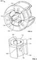
- FIG. 1is an exploded view of a drive coupler of a blending system, in accordance with various disclosed aspects.
- FIG. 2is a partial, cross-sectional view of a drive socket and a cap of the drive coupler of FIG. 1 , in accordance with various disclosed aspects.
- FIG. 3is a bottom, perspective view of a drive socket of FIG. 1 , in accordance with various disclosed aspects.
- FIG. 4is a partial, transparent view of a drive insert of the drive coupler of FIG. 1 , in accordance with various disclosed aspects.
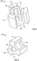
- FIG. 5is a perspective view of a second insert assembled with a clip of the drive coupler of FIG. 1 , in accordance with various disclosed aspects.
- FIG. 6is a top, perspective view of a clip of the drive coupler of FIG. 1 , in accordance with various disclosed aspects.
- FIG. 7is a bottom, perspective view of a clip of the drive coupler of FIG. 1 , in accordance with various disclosed aspects.
- FIG. 8is a top, perspective view of a second insert of the drive coupler of FIG. 1 , in accordance with various disclosed aspects.
- FIG. 9is a bottom, perspective view of a second insert of the drive coupler of FIG. 1 , in accordance with various disclosed aspects.
- FIG. 10is a top, perspective view of a first insert of the drive coupler of FIG. 1 , in accordance with various disclosed aspects.
- FIG. 11is a bottom, perspective view of a first insert of the drive coupler of FIG. 1 , in accordance with various disclosed aspects.
- FIG. 12is a top, perspective view of a drive insert of the drive coupler of FIG. 1 , in accordance with various disclosed aspects.
- FIG. 13is a bottom, perspective view of a drive insert of the drive coupler of FIG. 1 , in accordance with various disclosed aspects.
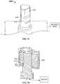
- FIG. 14is a perspective view of a drive shaft of a blender system, in accordance with various disclosed aspects.
- FIG. 15is a partial, cross-sectional view of a drive shaft and a drive insert of a blender system, in accordance with various disclosed aspects.
- FIG. 16is a perspective view of a blender base and a blending container, in accordance with various disclosed aspects.
- the words “example” and “exemplary”mean an instance, or illustration.
- the words “example” or “exemplary”do not indicate a key or preferred aspect or embodiment.
- the word “or”is intended to be inclusive rather an exclusive, unless context suggests otherwise.
- the phrase “A employs B or C,”includes any inclusive permutation (e.g., A employs B; A employs C; or A employs both B and C).
- the articles “a” and “an”are generally intended to mean “one or more” unless context suggest otherwise.
- various embodiments described hereinmay include other components and/or functionality. It is further noted that while various embodiments refer to a blender or a blending system, various other systems may be utilized in view of embodiments described herein. For example, embodiments may be utilized in food processor systems, mixing systems, hand-held blending systems, various other food preparation systems, and the like. As such, references to a blender, blending system, and the like, are understood to include food processor systems, and other mixing systems. Such systems generally include a blender base that may include a motor, a controller, a display, a memory and a processor. Further, such systems may include a blending container and a blade assembly. The blade assembly, the blending container, and the blender base may removably or irremovably attach.
- the blending containermay be powered in any appropriate manner, such as disclosed in U.S. patent application Ser. No. 14/213,557, entitled Powered Blending Container, which is hereby incorporated by reference.
- Foodstuffmay be added to the blending container.
- non-food stuffmay be mixed or blended, such as paints, epoxies, construction material (e.g., mortar, cement, etc.), and the likes.
- the blending systemsmay include any household blender and/or any type of commercial blending system, including those with covers that may encapsulate or partially encapsulate the blender.
- commercial blending systemsmay include an overall blending system, such as a modular blending system that may include the blender along with other components, such as a cleaner, foodstuff storage device (including a refrigerator), an ice maker and/or dispenser, a foodstuff dispenser (a liquid or powder flavoring dispenser) or any other combination of such.
- a modular blending systemthat may include the blender along with other components, such as a cleaner, foodstuff storage device (including a refrigerator), an ice maker and/or dispenser, a foodstuff dispenser (a liquid or powder flavoring dispenser) or any other combination of such.
- blended productsmay include drinks, frozen drinks, smoothies, shakes, soups, purees, sorbets, butter (nut), dips or the likes. It is noted that various other blended products may result from blending ingredients. Accordingly, terms such as “blended product” or “drink” may be used interchangeably unless context suggests otherwise or warrants a particular distinction among such terms. Moreover, such terms are not intended to limit possible blended products and should be viewed as examples of possible blended products.
- rotation of blades in a containermay produce a large amount of noise that may be unpleasant for a user.
- blade assemblies and/or blending containers of the blending devicesmay vibrate during operation, which may contribute to such noise.
- the vibration and noisemay increase at high speeds or blending of particular ingredients.
- molding of thick sections or parts for a blade assemblymay provide challenges.
- a spring clip within a drive coupleris sometimes used to prevent a drive shaft from disengaging the coupler in the axial direction. The force exerted by a spring clip, however, may cause misalignment between the drive shaft and a blade assembly shaft. That misalignment may cause increased noise and/or reduce efficiency.
- a blender assemblymay include a blender base housing a motor.
- the motormay include a drive shaft that operatively drives an attachable blade assembly.
- the drive shaftmay include a drive coupler that may be attached (e.g., removably or irremovably) from the drive shaft.
- the drive couplermay comprise a chamber that may receive a drive shaft of a blade assembly. The motor may rotate the drive shaft to drive the blade assembly.
- a drive coupler assemblymay be operatively attached to a drive shaft of a blending system.
- the drive couplermay comprise a drive socket that operatively receives a drive shaft of a blade assembly, and an elastomeric insert disposed between the drive socket and the drive shaft of the motor.
- the elastomeric insertmay comprise an elastomeric material, including, without limitation, a rubber. It is noted that the elastomeric insert may be under compression within the drive socket. The compression may stiffen the elastomeric insert, such that the elastomeric insert is radially and axially rigid.
- the dampening membermay maintain sound and/or vibration dampening properties while providing a stiffened coupler.
- rubber and plasticare identified herein as potential elastomeric materials
- the present teachingsmay include any kind of elastomeric material, including, without limitation, rubber, plastic (e.g., thermoplastic vulcanizate or other thermoplastic elastomers), a combination of rubber and plastic, a foam material, a compressed foam material, and any combination of such.
- FIG. 1illustrates a drive coupler 100 for a blender system, in accordance with various described embodiments.
- the blender systemmay include additional or other components not shown for brevity, such as a container, blender base, a blade assembly, etc.
- the blender systemmay include a blender base that houses a motor.
- the motormay include a drive shaft and the drive coupler 100 may be attachable (e.g., irremovably or removably) to the drive shaft. It is noted that while components of the drive coupler 100 are described as separate components, various components may be monolithically formed.
- the drive coupler 100may primarily comprise a ring insert 102 , a drive socket 120 that may receive the ring insert 102 , a drive insert 130 (which may include a second insert 132 , a clip 150 , and a first insert 133 ), and a cap 180 .
- the components of the drive coupler 100may be preassembled and/or may be assembled at a factory or by an end user.
- the drive insert 130may be preassembled by a manufacturer or a supplier.
- Drive socket 120may include the body 116 that may comprise one or more chambers, such as splined chamber 112 and drive chamber 114 .
- the splined chamber 112may include one or more splines 122 , threads, or other mechanisms for receiving a shaft of a blade assembly.
- the splined chamber 112may include a ring receiving portion 124 (as shown in FIG. 1 ) that may be sized and shaped to receive the ring insert 102 .
- the ring receiving portion 124may comprise one or more geometric features, magnets, or other components that may allow splines 110 of ring insert 102 to align with splines 122 of the splined chamber 112 .
- the ring insert 102may include one or more notches 108 sized and shaped to receive one or more protrusions 129 (as shown in FIG. 1 ) within the ring receiving portion 124 .
- the ring insert 102may include i notches 108 disposed along a perimeter of the ring insert 102 .
- the ring receiving portion 124may include j protrusions 129 sized and shaped to mate with the one or more notches 108 , where i and j are numbers.
- the notches 108 and protrusions 129may generally prevent the ring insert 102 from rotating with respect to the drive socket 120 .
- the drive socket 120may include a top portion 125 and the body 116 .
- the top portion 125 and the body 116may comprise one or more components or pieces that may be joined together or of unitary construction.
- the top portion 125may include a flange 121 that may generally retain or secure the ring insert 102 within the ring receiving portion 124 .
- the ring insert 102may be overmolded with the flange 121 or the like.
- the ring receiving portion 124may be sealed by the flange 121 and the ring insert 102 .
- the ring insert 102may comprise a metal or other material having properties that prevent the ring insert 102 from deforming due to operation of the blender system.
- the drive socket 120may comprise a material that may be more susceptible to deformation, such as plastic, but may be lighter in weight, have vibration absorbing properties, or the like. As such, the ring insert 102 may generally bare the load from torque applied to the blade assembly. It is noted, however, that the ring insert 102 may extend along part or all of the splined chamber 112 .
- the drive socket 120may comprise a metal material and the drive coupler 100 may not include a ring insert 102 .
- the drive chamber 114 of the drive socket 120may be sized and shaped for receiving the drive insert 130 .
- the drive chamber 114may include one or more geometric formations 126 that may allow the drive insert 130 to mate with the drive chamber 114 , such as operatively mating. Such formations 126 may allow the drive insert 130 to rotate the drive socket 120 in response to rotation of the drive shaft of the motor, as described in more detail herein.
- the cap 180may be attached (e.g., removably or irremovably) to the drive socket 120 .
- the cap 180may be welded, overmolded, press-fit, or otherwise attached to the drive socket 120 proximal the drive chamber 114 .
- the cap 180may be welded to the drive socket 120 after the drive insert 130 is disposed within the drive chamber 114 . This may prevent (e.g., or reduce the chances of) the drive socket 120 from separating from the drive insert 130 .
- the drive insert 130may comprise the second insert 132 , the clip 150 , and the first insert 133 .
- second insert 132may be sized and shaped to receive the clip 150 and the first insert 133 receive the second insert 132 , such that at least a portion of the second insert 132 nests with the first insert 133 .
- the components of drive insert 130may be configured for friction-fit or press-fit.
- the first insert 133may comprise an elastomeric insert that may compress the second insert 132 and the clip 150 when the drive insert 130 is operatively assembled.
- Second insert 132may comprise a metal (e.g., patterned metal, etc.), plastic or the like.
- the second insert 132may be formed via molding, 3-D printing, machining, or the like.
- the second insert 132may comprise a body 140 having one or more protrusions 142 extending therefrom.
- Body 140may extend between a proximal end 164 and distal end 165 .
- One or more slots 138may be disposed between the one or more protrusions 142 . It is noted that while second insert 132 is shown as comprising three protrusions 142 and three slots 138 , the second insert 132 may comprise a different number of protrusions 142 or slots 138 , and/or no protrusions 142 or slots 138 .
- second insert 132may include one more teeth 144 extending outwardly from the protrusions 142 .
- the one or more teeth 144may allow a drive shaft to rotate the drive socket 120 and/or the blade assembly of a blender system.
- the teeth 144 and the protrusions 142may be sized and shaped to receive the clip 150 .
- at least a portion of the teeth 144 and the protrusions 142may form a seat 136 that may be sized and shaped to receive the clip 150 .
- the seat 136may generally support or contact a portion of the clip 150 .
- clip 150may include a ring 152 having an inner perimeter 158 and an outer perimeter 160 .
- the seat 136may be sized and shaped to receive the ring 152 .
- the clip 150may include one or more tabs 154 extending from the ring 152 .
- the tabs 154may comprise spring clips.
- the tabs 154may comprise a material having spring qualities that bias the tabs 154 towards a particular orientation.
- Tabs 154may include one or more cleats 156 extending therefrom. These cleats 156 may couple or mate with grooves of a drive shaft, as described in more detail herein.
- the clip 150may be paired or otherwise coupled to the second insert 132 , such that the ring 152 rests on or abuts the seat 135 .
- the tabs 154may extend within an aperture 162 of the second insert 132 .
- the tabs 154may generally align with the slots 138 . This may allow the tabs 154 to maintain some room for flexibility.
- the aperture 162may comprise a perimeter 148 that may comprise one or more sides or corners 146 .
- the perimeter 148may comprise a shape representing a triangle with squared off vertices.
- the first insert 133may comprise a proximal end 166 and a distal end 168 .
- a body 172may extend between the proximal end 166 and the distal end 168 .
- the body 172may be sized and shaped to generally allow the assembled clip 150 and second insert 132 to nest therein.
- the body 172may comprise an internal perimeter or profile that mirrors the external perimeter or profile of the assembled clip 150 and second insert 132 .
- the assembled clip 150 and second insert 132may be inserted at the distal end 168 , with a proximal end 164 of the assembled clip 150 and second insert 132 entering the distal end 168 first. That is, when inserted, the proximal end 164 (e.g., the end proximal the ring 152 ) will abut the proximal end 166 of the first insert 133 .
- the first insert 133may include one or more flaps 176 that may be manipulated and/or bent such that the assembled clip 150 and second insert 132 may be inserted in the first insert 133 . Once fully inserted, the flaps 176 may be allowed to return substantially to their original position.
- a second set of flaps 178 at the proximal end 166may abut the proximal end 164 of the clip 150 and second insert 132 .
- These flaps 176 and/or 178may generally prevent the clip 150 and second insert 132 from being removed from the first insert 133 . It is noted, however, that a user may bend or otherwise reposition the flaps 176 and/or 178 to remove one or more of the clip 150 and second insert 132 . In this aspect, portions of the drive coupler 100 may be replaced.
- the drive shaft 400may comprise a drive shaft of a blender motor (not shown) that may operatively rotate the drive shaft.
- the drive shaft 400may comprise a perimeter 402 that may generally mirror the perimeter of aperture 162 of the drive coupler 100 .
- the perimeter 402may comprise one or more sides, bends, or other geometric formations.
- the perimeter 402may comprise a triangular-shape with squared, chamfered, tapered, rounded, or otherwise modified vertices.
- the triangular-shapemay generally allow for operative engagement with the drive coupler 100 .
- the shapemoreover, may be cheaper to produce than square, rectangular, hexagonal, splined or other shaped versions.
- the tolerances for the triangular-shapemay be greater than those of 4 or more sided polygonal-shapes, splined shapes, or the like. The greater tolerance may allow for more efficient and less costly production while maintaining the ability for drive shaft 400 to operatively couple with the drive coupler 100 .
- the drive shaft 400may include one or more receiving member 408 , which may comprise grooves that may mate with cleats 156 of clip 150 .
- the tabs 154may bend or deform. Once the cleats 156 reach the receiving members 408 , the tabs 154 may snap or clip into place. This may prevent the drive coupler 100 from becoming dislodged from the drive shaft 400 .
- the drive shaft 400may include one or more ledges 412 that may operatively allow a portion of the drive coupler 100 to rest thereon.
- the first insert 133 and the second insert 132may be disposed between the drive shaft 400 and the drive socket 120 .
- At least one of the first insert 133 and the second insert 132may comprise an elastomeric material.
- the elastomeric materialmay, for example, absorb vibrations, reduce noise, reduce wobble, increase efficiency, or the like.
- the first insert 133may generally prevent direct contact between the drive socket 120 and the drive shaft 400 .
- the first insert 133may prevent direct contact between rigid components, such as the second insert 132 and the drive socket 120 .
- the insertsmay comprise a single component.
- the drive socket 120may comprise an elastomeric material deposited with the drive chamber 114 via chemical deposition or the like.
- the drive coupler 100may not include first insert 133 and/or first insert 133 may be considered as integrally formed with the drive coupler 100 .
- FIGS. 14-15do not illustrate the drive socket 120 , ring insert 102 and/or cap 180 for readability and brevity.
- the drive insert 130may be inserted or assembled with such components prior to attaching the drive insert 130 to the drive shaft 400 . It is noted, however, that the drive insert 130 may be attached to the drive socket 120 and the like after the drive insert 130 is attached to the drive shaft 400 .
- a drive couplermay comprise different components, shapes, or the like.
- a locking pinmay operatively lock the drive socket 120 into place with the drive insert 130 .
- drive socketsmay or may not be splined.
- various other mechanismsmay be utilized for attaching a blade assembly to a drive coupler. While embodiments have been illustrated as comprising a clip, tabs, or the like, a drive coupler may be attached to a drive shaft by various other methods, such as threaded connections, screws, bolts, rivets, other fasteners, magnetic connections, welding, or the like.
- FIG. 16depicts a blending base 18 and blending container 14 that may be utilized in accordance with disclosed aspects.
- the container 14may include a lid 22 , a body 26 , a handle 30 , and a base 34 .
- the blending container 14may have a power source 36 positioned in the blending container 14 at any appropriate location.
- a blade assembly 56may be operatively coupled to the container 14 .
- the blade assembly 56may include a splined shaft to be driven by the drive coupler 100 .
Landscapes
- Engineering & Computer Science (AREA)
- Mechanical Engineering (AREA)
- Food Science & Technology (AREA)
- Food-Manufacturing Devices (AREA)
Abstract
Description
Claims (18)
Priority Applications (1)
| Application Number | Priority Date | Filing Date | Title |
|---|---|---|---|
| US15/619,652US11033153B2 (en) | 2016-06-10 | 2017-06-12 | Drive coupler for blender |
Applications Claiming Priority (2)
| Application Number | Priority Date | Filing Date | Title |
|---|---|---|---|
| US201662348313P | 2016-06-10 | 2016-06-10 | |
| US15/619,652US11033153B2 (en) | 2016-06-10 | 2017-06-12 | Drive coupler for blender |
Publications (2)
| Publication Number | Publication Date |
|---|---|
| US20180042427A1 US20180042427A1 (en) | 2018-02-15 |
| US11033153B2true US11033153B2 (en) | 2021-06-15 |
Family
ID=61160487
Family Applications (1)
| Application Number | Title | Priority Date | Filing Date |
|---|---|---|---|
| US15/619,652ActiveUS11033153B2 (en) | 2016-06-10 | 2017-06-12 | Drive coupler for blender |
Country Status (1)
| Country | Link |
|---|---|
| US (1) | US11033153B2 (en) |
Families Citing this family (5)
| Publication number | Priority date | Publication date | Assignee | Title |
|---|---|---|---|---|
| EP3530160B1 (en)* | 2018-02-21 | 2020-08-05 | Vorwerk & Co. Interholding GmbH | Food preparation device with lock |
| WO2019183755A1 (en)* | 2018-03-26 | 2019-10-03 | 韩伟杰 | Multi-functional food processor main machine |
| CN111053470B (en)* | 2018-10-17 | 2021-01-22 | 广东美的白色家电技术创新中心有限公司 | Knife tackle spare and cooking machine that has it |
| US11974699B2 (en)* | 2021-04-05 | 2024-05-07 | Conair Llc | Drive coupling for a food processing device |
| WO2025144898A1 (en)* | 2023-12-28 | 2025-07-03 | Vita-Mix Management Corporation | Non-rigid gasket for sound and vibration attenuation in blender systems and methods of use thereof |
Citations (155)
| Publication number | Priority date | Publication date | Assignee | Title |
|---|---|---|---|---|
| US298503A (en) | 1884-05-13 | Egg and cake beater | ||
| US460265A (en) | 1891-09-29 | Oooooo | ||
| US747249A (en) | 1903-07-27 | 1903-12-15 | Charles H Smith | Graduate. |
| US2282866A (en) | 1939-11-27 | 1942-05-12 | Hagen Harold | Electric liquid mixer and heater |
| US2345749A (en) | 1943-10-06 | 1944-04-04 | Woodworth Co N A | Gauge handle |
| US2370725A (en) | 1942-12-03 | 1945-03-06 | Herman L Gordon | Wire connector |
| US2639904A (en) | 1949-12-13 | 1953-05-26 | G M Lab Inc | Mixer |
| US2670227A (en) | 1949-10-28 | 1954-02-23 | Stromberg Carlson Co | Control knob and shaft connection |
| US2676506A (en) | 1952-02-28 | 1954-04-27 | John M Schultz | Bolt-retaining socket wrench |
| US2716564A (en) | 1949-09-27 | 1955-08-30 | Sandvikens Jernverks Ab | Arrangement for attaching a drill crown to a drill steel or drill steels to each other |
| US2722114A (en)* | 1952-09-13 | 1955-11-01 | Knapp Monarch Co | Coupling silencer |
| US2788038A (en) | 1954-11-02 | 1957-04-09 | Standard Electronics Corp | Rotor |
| US3175594A (en) | 1961-10-23 | 1965-03-30 | Sunbeam Corp | Disintegrator and mixer |
| US3233497A (en) | 1963-12-12 | 1966-02-08 | Ramsey Corp | Spring finger retaining rings |
| US3368800A (en) | 1965-04-13 | 1968-02-13 | Vita Mix Corp | Blender |
| US3388934A (en) | 1965-12-16 | 1968-06-18 | Gen Motors Corp | Hub and smooth shaft spring key arrangement |
| US3543605A (en) | 1969-05-14 | 1970-12-01 | Gen Electric | Control knob with adjustable connection means |
| US3884423A (en) | 1973-03-26 | 1975-05-20 | Hobart Corp | Impeller for food preparing machine |
| US4087053A (en) | 1977-01-24 | 1978-05-02 | Dynamics Corporation Of America | Liquefier-comminuter |
| US4256010A (en) | 1978-03-02 | 1981-03-17 | Petrie John A | Beveled retaining ring and method for constructing the same |
| US4264216A (en) | 1979-05-21 | 1981-04-28 | Ronco Teleproducts, Inc. | Apparatus and method for beating an egg within its own shell |
| EP0041082A1 (en) | 1980-05-30 | 1981-12-09 | Steven Davis Sandor | Method and apparatus for making hot beverages |
| US4335860A (en) | 1979-02-07 | 1982-06-22 | Braun Ag | Electric household blender with motor enabled by lid locking |
| US4462694A (en) | 1983-08-23 | 1984-07-31 | Sunbeam Corporation | Agitator assembly for use in blender appliance |
| US4471915A (en) | 1982-08-17 | 1984-09-18 | Scovill Inc. | Food processor having enlarged feed tube with safety guard |
| US4678881A (en) | 1985-05-28 | 1987-07-07 | The Electricity Council | Induction apparatus for heating and mixing a fluid |
| US4741482A (en) | 1979-08-29 | 1988-05-03 | Robot-Coupe S.A. | Magnetic safety switch device for food processor |
| US4750878A (en) | 1985-08-09 | 1988-06-14 | Automotive Products Plc | Retainer bushing |
| US4783173A (en) | 1987-10-26 | 1988-11-08 | Sunbeam Corporation | Combined washer and collar for supporting a motor |
| US4885917A (en) | 1986-10-20 | 1989-12-12 | Donald Spector | Household appliance for making frozen food products |
| US4889248A (en) | 1988-02-04 | 1989-12-26 | Thermo Blender Inc. | Combination container cap and blender adapter |
| US4913555A (en) | 1987-01-14 | 1990-04-03 | Sanyo Electric Co., Ltd. | Whipping machine |
| US5131785A (en) | 1990-12-28 | 1992-07-21 | Tachi-S Co. Ltd. | Handle securing arrangement |
| US5273358A (en) | 1992-04-13 | 1993-12-28 | Vita-Mix Corporation | Quiet and efficient motor cooling fan assembly for a blender |
| US5274207A (en) | 1990-08-13 | 1993-12-28 | Electricity Association Technology Limited | Induction heater |
| US5365807A (en) | 1993-06-24 | 1994-11-22 | Darrah Scott A | Through-hole socket |
| US5368384A (en) | 1993-08-20 | 1994-11-29 | Duncan; J. Kenneth | Hand-held mixing device with heating element |
| US5478149A (en) | 1995-04-24 | 1995-12-26 | Magnetic Mixers, Inc. | Magnetic mixer |
| US5567049A (en) | 1994-09-02 | 1996-10-22 | Moulinex S.A. | Domestic mixer with safety device |
| EP0754602A1 (en) | 1995-07-21 | 1997-01-22 | Textron Inc. | Mounting assembly for air bag |
| US5674026A (en) | 1994-02-28 | 1997-10-07 | Unisia Jecs Corporation | Shaft coupling structure of drive shaft |
| US5852968A (en) | 1997-06-26 | 1998-12-29 | Ab Hallde Maskiner | Food processors |
| US5855431A (en) | 1996-08-09 | 1999-01-05 | Coastal Sales Associates, Inc. | Rotating mixer and tray |
| US6095677A (en) | 1999-01-12 | 2000-08-01 | Island Oasis Frozen Cocktail Co., Inc. | Magnetic drive blender |
| US6149035A (en) | 1999-08-12 | 2000-11-21 | Karma, Inc. | Food and beverage dispensing system |
| US6318247B1 (en) | 1998-04-02 | 2001-11-20 | Sunbeam Products, Inc. | Appliance for preparation of heated and stirred beverages and foods |
| US6325312B1 (en) | 1999-05-14 | 2001-12-04 | Island Oasis Frozen Cocktail Company, Inc. | Insertion guide construction for a food processor receptacle |
| US6336603B1 (en) | 1999-01-12 | 2002-01-08 | Island Oasis Frozen Cocktail Company, Inc. | Food processing apparatus including magnetic drive |
| US20020071340A1 (en) | 2000-08-31 | 2002-06-13 | Jan Juriga | Kitchen appliance having a removable container and having protection means which perform their protective function in the case of removal of the container |
| US6416215B1 (en) | 1999-12-14 | 2002-07-09 | University Of Kentucky Research Foundation | Pumping or mixing system using a levitating magnetic element |
| US6460368B1 (en) | 2001-05-30 | 2002-10-08 | Alfonso Fabian Grande Damaso | Magnetic drive for an icing machine scraping blade |
| US6494390B1 (en) | 2000-05-24 | 2002-12-17 | Northwestern University | Solid state shear pulverization of multicomponent polymeric waste |
| US6513966B1 (en) | 1999-08-05 | 2003-02-04 | Dualit Limited | Electric blender with safety interlock arrangement |
| US6568843B1 (en) | 2002-07-03 | 2003-05-27 | A-Pi Lai | Safety device for a blender |
| US6629492B1 (en) | 2002-12-06 | 2003-10-07 | Wen-Jing Li | Juicer having a safe power connection function |
| US6632013B2 (en) | 2001-04-02 | 2003-10-14 | Sunbeam Products, Inc. | Blender with food processor capabilities |
| USD480915S1 (en) | 2003-01-30 | 2003-10-21 | Vita-Mix Corporation | Container for a blender |
| US20030198127A1 (en) | 2001-08-31 | 2003-10-23 | Xerox Corporation | High intensity blending tool with optimized risers for increased intensity when blending toners |
| US6637681B1 (en) | 1998-10-06 | 2003-10-28 | Arno S.A. | Safety system to prevent the functioning of a blender or food processor if the top of its cup is not in place |
| US6712497B2 (en) | 2001-05-22 | 2004-03-30 | Shurflo Pump Manufacturing Co., Inc. | Material processing appliance and associated magnetic drive unit |
| US6758593B1 (en) | 2000-10-09 | 2004-07-06 | Levtech, Inc. | Pumping or mixing system using a levitating magnetic element, related system components, and related methods |
| US6793167B2 (en) | 1999-01-12 | 2004-09-21 | Island Oasis Cocktail Company, Inc. | Food processing apparatus including magnetic drive |
| US20040206837A1 (en) | 2003-04-16 | 2004-10-21 | Ming-Tsung Lee | Food processor blade unit |
| US6910800B2 (en) | 2002-08-27 | 2005-06-28 | Eupa International Corporation | Blender having a top cover provided with a switch actuating block |
| US20050174882A1 (en) | 2004-02-09 | 2005-08-11 | Krasne Mark T. | Combination mixing and drinking vessel |
| EP1688046A1 (en) | 2005-01-31 | 2006-08-09 | Ali SpA | machine for making and dispensing ice drinks |
| US20060176765A1 (en) | 2005-02-04 | 2006-08-10 | Pryor Ernest B Jr | Dispensing blender |
| USD526531S1 (en) | 2005-03-18 | 2006-08-15 | Whirlpool Corporation | Blender |
| US20060275075A1 (en) | 2005-05-20 | 2006-12-07 | Katz Jonathan M | Drive coupler for a blender |
| USD533395S1 (en) | 2005-03-18 | 2006-12-12 | Whirlpool Corporation | Blender |
| US20060286255A1 (en) | 2005-06-18 | 2006-12-21 | Zhaoxia Xu | Automated Soup Making Apparatus |
| US7235339B2 (en) | 2004-10-28 | 2007-06-26 | Xerox Corporation | Method of blending toners using a high intensity blending tool with shaped risers for decreased toner agglomeration |
| US7270156B2 (en) | 2000-11-13 | 2007-09-18 | Back To Basics Products, Llc | Beverage mixer and heater |
| US7278598B2 (en) | 2004-01-23 | 2007-10-09 | Vita-Mix Corporation | Blender blade |
| USD552419S1 (en) | 2006-08-18 | 2007-10-09 | Sunbeam Products, Inc. | Blender base |
| US7314307B2 (en) | 2006-01-17 | 2008-01-01 | Ying Lin Cai | Automatic motor-driven blender cup with a leak-free magnetic stirring apparatus |
| US7318666B1 (en) | 2007-04-24 | 2008-01-15 | Kuan-Chih Lin | Safety device for blender |
| US20080037360A1 (en) | 2005-05-27 | 2008-02-14 | Mcgill Shane R | Blending Assembly |
| US20080089170A1 (en) | 2006-10-16 | 2008-04-17 | Hamilton Beach/Proctor-Silex, Inc. | Mixing device configured to blend food |
| US20080098905A1 (en) | 2006-10-31 | 2008-05-01 | Hamilton Beach/Proctor-Silex, Inc. | Blender for Blending Foodstuff |
| US7387269B2 (en) | 2005-03-18 | 2008-06-17 | Whirlpool Corporation | Drive coupler for a food preparation device |
| US7407320B1 (en) | 2007-08-14 | 2008-08-05 | Kuan-Chih Lin | Blender with safety device |
| US20080198688A1 (en) | 2007-02-19 | 2008-08-21 | Zheng Peng | Blend soup maker |
| USD577537S1 (en) | 2008-03-12 | 2008-09-30 | Whirlpool Corporation | Blender |
| US20080264927A1 (en) | 2007-04-27 | 2008-10-30 | Zheng Peng | Cooking range having a motorized stove base |
| USD587526S1 (en) | 2008-07-30 | 2009-03-03 | Vita-Mix Corporation | Container for a blender |
| USD588406S1 (en) | 2008-03-18 | 2009-03-17 | Vita-Mix Corporation | Container for a blender |
| US7507049B2 (en) | 2003-06-13 | 2009-03-24 | Barnes Group Inc. | Locking ring |
| US20090084274A1 (en) | 2005-08-26 | 2009-04-02 | Bsh Bosch Und Siemens Hausgerate Gmbh | Kitchen appliance comprising a safety system and method for operating a kitchen appliance |
| US7530510B2 (en) | 2004-03-19 | 2009-05-12 | Hamilton Beach Brands, Inc. | Storage food processor |
| US20090186139A1 (en) | 2008-01-17 | 2009-07-23 | Marinela Luminita Dragan | Steam -Heat-Only, Food-Preparation Bowl Structure and Related Methodology |
| US20090260523A1 (en) | 2008-04-17 | 2009-10-22 | Zheng Peng | Blender |
| USD605462S1 (en) | 2009-06-09 | 2009-12-08 | Sunbeam Products, Inc. | Blender |
| US7641380B2 (en) | 2007-02-16 | 2010-01-05 | Sunbeam Products, Inc. | Blender/food processor blade arrangement for small throated blender jars |
| US20100018982A1 (en) | 2008-07-24 | 2010-01-28 | Pei-Chuan Liu | Heating and cooling cup |
| US20100044303A1 (en) | 2006-11-24 | 2010-02-25 | Cummins Filtration Ip Inc. | Filtration cartridge co-operating with a central tube and comprising a radially-retained seal mounted in a cavity for co-operating with said tube |
| US20100046323A1 (en) | 2007-02-08 | 2010-02-25 | Linsheng Walter Tien | Magnetic Stirring Devices and Methods |
| USD617145S1 (en) | 2010-01-21 | 2010-06-08 | Sunbeam Products, Inc. | Blender |
| EP2210542A1 (en) | 2009-01-21 | 2010-07-28 | Jané S.A. | Device for cooking, heating and/or defrosting food while also blending it |
| USD621656S1 (en) | 2009-11-02 | 2010-08-17 | Vita-Mix Corporation | Blender container |
| CN101904700A (en) | 2010-08-04 | 2010-12-08 | 新兴县万事泰不锈钢制品有限公司 | Milk foam machine directly driven by motor |
| US7871196B2 (en) | 2007-08-16 | 2011-01-18 | Kuan-Chih Lin | Juicer safety device |
| US7905728B2 (en) | 2007-10-05 | 2011-03-15 | Twister Tube, Ltd. | Device and method for generating vortex |
| US20110186172A1 (en) | 2010-02-01 | 2011-08-04 | Oasis Frozen Cocktail Company, Inc. | Blender with feature for dispensing product by weight |
| USD642857S1 (en) | 2010-07-05 | 2011-08-09 | Pi-Design Ag | Blender |
| USD644480S1 (en) | 2011-02-25 | 2011-09-06 | Whirlpool Corporation | Food processor |
| WO2011113083A1 (en) | 2010-03-18 | 2011-09-22 | Breville Pty Limited | Combination juicer-blender |
| US20110232506A1 (en) | 2009-01-09 | 2011-09-29 | Jianming Cai | Liquid Food Heating, Stirring and Foaming Cup |
| US20110241503A1 (en) | 2004-01-12 | 2011-10-06 | Lee Simon | Decorative commercial or professional kitchen or food service area appliance unit with interchangeable form fitting cover and a facade panel |
| US8087818B2 (en) | 2008-12-03 | 2012-01-03 | Whirlpool Corporation | Blade-motor coupler for a blender |
| WO2012044306A1 (en) | 2010-09-30 | 2012-04-05 | Vita-Mix Corporation | Blender blade |
| US8186872B2 (en) | 2004-11-08 | 2012-05-29 | Cosmetic Technologies | Automated customized cosmetic dispenser |
| USD660642S1 (en) | 2011-12-06 | 2012-05-29 | Vita-Mix Corporation | Blender base |
| USD662359S1 (en) | 2011-12-06 | 2012-06-26 | Vita-Mix Corporation | Blender container |
| US8220730B2 (en) | 2005-06-03 | 2012-07-17 | Kenwood Limited | Interlock system |
| US8226021B2 (en) | 2007-06-27 | 2012-07-24 | Ian Geoffrey Wilson | Food blender subassembly and method |
| US8230774B1 (en) | 2008-01-11 | 2012-07-31 | Hunte Karen A | Multi-unit bottle preparation device |
| US8240909B2 (en) | 2009-07-17 | 2012-08-14 | Whirlpool Corporation | Blender jar interlock |
| US20120206995A1 (en) | 2011-02-10 | 2012-08-16 | Andy Wu | Blender Lid Safety Protection Device |
| USD667259S1 (en) | 2012-03-06 | 2012-09-18 | E. Mishan & Sons, Inc. | Blender base |
| USD667260S1 (en) | 2012-03-06 | 2012-09-18 | E. Mishan & Sons, Inc. | Blender base |
| USD667261S1 (en) | 2012-03-06 | 2012-09-18 | E. Mishan & Sons, Inc. | Blender base |
| USD668100S1 (en) | 2012-04-20 | 2012-10-02 | Sunbeam Products, Inc. | Blender base |
| US8282268B2 (en) | 2009-02-24 | 2012-10-09 | Island Oasis Frozen Cocktail Co., Inc. | Magnetic drive for food processing apparatus |
| US20120294109A1 (en) | 2011-05-16 | 2012-11-22 | Boozer Richard D | Blender base |
| US8376253B2 (en) | 2007-08-14 | 2013-02-19 | Bsh Bosch Und Siemens Hausgeraete Gmbh | Method for operating a food processor |
| US20130043337A1 (en) | 2011-08-15 | 2013-02-21 | Steve Rukavina | Apparatus for controlling the blending of drinks |
| USD677976S1 (en) | 2012-10-31 | 2013-03-19 | Sunbeam Products, Inc. | Blender base |
| USD678727S1 (en) | 2011-11-14 | 2013-03-26 | Vita-Mix Corporation | Container |
| US8403555B2 (en) | 2011-02-16 | 2013-03-26 | Quanzhou Yida Home Appliance Industry Co., Ltd. | High-speed blending, heating and temperature sensing structure of electric blender |
| US8444076B2 (en) | 2010-09-30 | 2013-05-21 | Vita-Mix Corporation | Blender blade |
| US8480292B2 (en) | 2010-06-01 | 2013-07-09 | Boris Dushine | Systems, apparatus and methods to reconstitute dehydrated drinks |
| US8529120B2 (en) | 2008-03-18 | 2013-09-10 | Vita-Mix Corporation | Blender container and cover |
| USD690152S1 (en) | 2012-04-20 | 2013-09-24 | Sunbeam Products, Inc. | Appliance base |
| US8550388B2 (en) | 2010-03-15 | 2013-10-08 | Moog Inc. | Drive circuit with integrated power factor correction for blender/shaver machine |
| USD694573S1 (en) | 2013-03-01 | 2013-12-03 | Whirlpool Corporation | Blender base |
| US20130319034A1 (en) | 2011-06-23 | 2013-12-05 | Sunbeam Products, Inc. | Mixed Beverage Maker |
| US20130344204A1 (en) | 2012-06-22 | 2013-12-26 | Mark E. Goodson | Beverage Mixing System and Method |
| US8621990B2 (en) | 2010-05-20 | 2014-01-07 | Johnson Electric S.A. | Household appliance |
| WO2014008926A1 (en) | 2012-07-10 | 2014-01-16 | Foster Jody James | System for the preparation of nursing bottles |
| USD702078S1 (en) | 2013-02-28 | 2014-04-08 | Euro-Pro Operating Llc | Blender base |
| US8702300B2 (en) | 2010-07-27 | 2014-04-22 | Euro-Pro Operating Llc | Food processor and attachment |
| US20140212566A1 (en) | 2013-01-30 | 2014-07-31 | Island Oasis Frozen Cocktail Co., Inc. | Frozen drink dispenser and method of dispensing frozen drinks |
| WO2014122254A2 (en) | 2013-02-07 | 2014-08-14 | Jörg Krug | A capsule for beverage dispensing apparatus |
| US8814072B2 (en) | 2011-11-30 | 2014-08-26 | Whirlpool Corporation | User-controlled adjustment mechanism for a food processing device |
| USD711688S1 (en) | 2013-08-15 | 2014-08-26 | Tristar Products, Inc. | Blender control panel |
| US20140270929A1 (en)* | 2013-03-15 | 2014-09-18 | Vita-Mix Corporation | Clip insert for drive coupler |
| USD730682S1 (en) | 2014-05-09 | 2015-06-02 | Euro-Pro Operating Llc | Blender base |
| USD733488S1 (en) | 2014-07-18 | 2015-07-07 | Euro-Pro Operating Llc | Blender base |
| US20150265983A1 (en) | 2014-03-20 | 2015-09-24 | Vita-Mix Corporation | Container/Lid/Blender Interlock |
| USD755003S1 (en) | 2014-11-21 | 2016-05-03 | Sunbeam Products, Inc. | Kitchen appliance base |
| USD765465S1 (en) | 2015-04-14 | 2016-09-06 | Tsann Kuen (Zhangzhou) Enterprise Co., Ltd. | Blender base |
| USD765462S1 (en) | 2015-02-19 | 2016-09-06 | Kenwood Limited | Blender base |
| USD771999S1 (en) | 2014-03-14 | 2016-11-22 | Vita-Mix Management Corporation | Blender base |
| USD797496S1 (en) | 2016-03-04 | 2017-09-19 | Vita-Mix Management Corporation | Blender base |
- 2017
- 2017-06-12USUS15/619,652patent/US11033153B2/enactiveActive
Patent Citations (171)
| Publication number | Priority date | Publication date | Assignee | Title |
|---|---|---|---|---|
| US298503A (en) | 1884-05-13 | Egg and cake beater | ||
| US460265A (en) | 1891-09-29 | Oooooo | ||
| US747249A (en) | 1903-07-27 | 1903-12-15 | Charles H Smith | Graduate. |
| US2282866A (en) | 1939-11-27 | 1942-05-12 | Hagen Harold | Electric liquid mixer and heater |
| US2370725A (en) | 1942-12-03 | 1945-03-06 | Herman L Gordon | Wire connector |
| US2345749A (en) | 1943-10-06 | 1944-04-04 | Woodworth Co N A | Gauge handle |
| US2716564A (en) | 1949-09-27 | 1955-08-30 | Sandvikens Jernverks Ab | Arrangement for attaching a drill crown to a drill steel or drill steels to each other |
| US2670227A (en) | 1949-10-28 | 1954-02-23 | Stromberg Carlson Co | Control knob and shaft connection |
| US2639904A (en) | 1949-12-13 | 1953-05-26 | G M Lab Inc | Mixer |
| US2676506A (en) | 1952-02-28 | 1954-04-27 | John M Schultz | Bolt-retaining socket wrench |
| US2722114A (en)* | 1952-09-13 | 1955-11-01 | Knapp Monarch Co | Coupling silencer |
| US2788038A (en) | 1954-11-02 | 1957-04-09 | Standard Electronics Corp | Rotor |
| US3175594A (en) | 1961-10-23 | 1965-03-30 | Sunbeam Corp | Disintegrator and mixer |
| US3233497A (en) | 1963-12-12 | 1966-02-08 | Ramsey Corp | Spring finger retaining rings |
| US3368800A (en) | 1965-04-13 | 1968-02-13 | Vita Mix Corp | Blender |
| US3388934A (en) | 1965-12-16 | 1968-06-18 | Gen Motors Corp | Hub and smooth shaft spring key arrangement |
| US3543605A (en) | 1969-05-14 | 1970-12-01 | Gen Electric | Control knob with adjustable connection means |
| US3884423A (en) | 1973-03-26 | 1975-05-20 | Hobart Corp | Impeller for food preparing machine |
| US4087053A (en) | 1977-01-24 | 1978-05-02 | Dynamics Corporation Of America | Liquefier-comminuter |
| US4256010A (en) | 1978-03-02 | 1981-03-17 | Petrie John A | Beveled retaining ring and method for constructing the same |
| US4335860A (en) | 1979-02-07 | 1982-06-22 | Braun Ag | Electric household blender with motor enabled by lid locking |
| US4264216A (en) | 1979-05-21 | 1981-04-28 | Ronco Teleproducts, Inc. | Apparatus and method for beating an egg within its own shell |
| US4741482A (en) | 1979-08-29 | 1988-05-03 | Robot-Coupe S.A. | Magnetic safety switch device for food processor |
| EP0041082A1 (en) | 1980-05-30 | 1981-12-09 | Steven Davis Sandor | Method and apparatus for making hot beverages |
| US4471915A (en) | 1982-08-17 | 1984-09-18 | Scovill Inc. | Food processor having enlarged feed tube with safety guard |
| US4462694A (en) | 1983-08-23 | 1984-07-31 | Sunbeam Corporation | Agitator assembly for use in blender appliance |
| US4678881A (en) | 1985-05-28 | 1987-07-07 | The Electricity Council | Induction apparatus for heating and mixing a fluid |
| US4750878A (en) | 1985-08-09 | 1988-06-14 | Automotive Products Plc | Retainer bushing |
| US4885917A (en) | 1986-10-20 | 1989-12-12 | Donald Spector | Household appliance for making frozen food products |
| US4913555A (en) | 1987-01-14 | 1990-04-03 | Sanyo Electric Co., Ltd. | Whipping machine |
| US4993840A (en) | 1987-01-14 | 1991-02-19 | Sanyo Electric Co., Ltd. | Cooking machine |
| US4783173A (en) | 1987-10-26 | 1988-11-08 | Sunbeam Corporation | Combined washer and collar for supporting a motor |
| US4889248A (en) | 1988-02-04 | 1989-12-26 | Thermo Blender Inc. | Combination container cap and blender adapter |
| US5274207A (en) | 1990-08-13 | 1993-12-28 | Electricity Association Technology Limited | Induction heater |
| US5131785A (en) | 1990-12-28 | 1992-07-21 | Tachi-S Co. Ltd. | Handle securing arrangement |
| US5273358A (en) | 1992-04-13 | 1993-12-28 | Vita-Mix Corporation | Quiet and efficient motor cooling fan assembly for a blender |
| US5365807A (en) | 1993-06-24 | 1994-11-22 | Darrah Scott A | Through-hole socket |
| US5368384A (en) | 1993-08-20 | 1994-11-29 | Duncan; J. Kenneth | Hand-held mixing device with heating element |
| US5674026A (en) | 1994-02-28 | 1997-10-07 | Unisia Jecs Corporation | Shaft coupling structure of drive shaft |
| US5567049A (en) | 1994-09-02 | 1996-10-22 | Moulinex S.A. | Domestic mixer with safety device |
| US5478149A (en) | 1995-04-24 | 1995-12-26 | Magnetic Mixers, Inc. | Magnetic mixer |
| EP0754602A1 (en) | 1995-07-21 | 1997-01-22 | Textron Inc. | Mounting assembly for air bag |
| US5855431A (en) | 1996-08-09 | 1999-01-05 | Coastal Sales Associates, Inc. | Rotating mixer and tray |
| US5852968A (en) | 1997-06-26 | 1998-12-29 | Ab Hallde Maskiner | Food processors |
| US6318247B1 (en) | 1998-04-02 | 2001-11-20 | Sunbeam Products, Inc. | Appliance for preparation of heated and stirred beverages and foods |
| US6637681B1 (en) | 1998-10-06 | 2003-10-28 | Arno S.A. | Safety system to prevent the functioning of a blender or food processor if the top of its cup is not in place |
| US6095677A (en) | 1999-01-12 | 2000-08-01 | Island Oasis Frozen Cocktail Co., Inc. | Magnetic drive blender |
| US6336603B1 (en) | 1999-01-12 | 2002-01-08 | Island Oasis Frozen Cocktail Company, Inc. | Food processing apparatus including magnetic drive |
| US6793167B2 (en) | 1999-01-12 | 2004-09-21 | Island Oasis Cocktail Company, Inc. | Food processing apparatus including magnetic drive |
| US6210033B1 (en) | 1999-01-12 | 2001-04-03 | Island Oasis Frozen Cocktail Co., Inc. | Magnetic drive blender |
| US6325312B1 (en) | 1999-05-14 | 2001-12-04 | Island Oasis Frozen Cocktail Company, Inc. | Insertion guide construction for a food processor receptacle |
| US6513966B1 (en) | 1999-08-05 | 2003-02-04 | Dualit Limited | Electric blender with safety interlock arrangement |
| US6149035A (en) | 1999-08-12 | 2000-11-21 | Karma, Inc. | Food and beverage dispensing system |
| US6416215B1 (en) | 1999-12-14 | 2002-07-09 | University Of Kentucky Research Foundation | Pumping or mixing system using a levitating magnetic element |
| US6494390B1 (en) | 2000-05-24 | 2002-12-17 | Northwestern University | Solid state shear pulverization of multicomponent polymeric waste |
| US6540394B2 (en) | 2000-08-31 | 2003-04-01 | Koninklijke Philips Electronics N.V. | Kitchen appliance having a removable container and having protection means which perform their protective function in the case of removal of the container |
| US20020071340A1 (en) | 2000-08-31 | 2002-06-13 | Jan Juriga | Kitchen appliance having a removable container and having protection means which perform their protective function in the case of removal of the container |
| US6899454B2 (en) | 2000-10-09 | 2005-05-31 | Levtech, Inc. | Set-up kit for a pumping or mixing system using a levitating magnetic element |
| US6758593B1 (en) | 2000-10-09 | 2004-07-06 | Levtech, Inc. | Pumping or mixing system using a levitating magnetic element, related system components, and related methods |
| US7270156B2 (en) | 2000-11-13 | 2007-09-18 | Back To Basics Products, Llc | Beverage mixer and heater |
| US6632013B2 (en) | 2001-04-02 | 2003-10-14 | Sunbeam Products, Inc. | Blender with food processor capabilities |
| US6712497B2 (en) | 2001-05-22 | 2004-03-30 | Shurflo Pump Manufacturing Co., Inc. | Material processing appliance and associated magnetic drive unit |
| US6460368B1 (en) | 2001-05-30 | 2002-10-08 | Alfonso Fabian Grande Damaso | Magnetic drive for an icing machine scraping blade |
| US20030198127A1 (en) | 2001-08-31 | 2003-10-23 | Xerox Corporation | High intensity blending tool with optimized risers for increased intensity when blending toners |
| US6568843B1 (en) | 2002-07-03 | 2003-05-27 | A-Pi Lai | Safety device for a blender |
| US6910800B2 (en) | 2002-08-27 | 2005-06-28 | Eupa International Corporation | Blender having a top cover provided with a switch actuating block |
| US6629492B1 (en) | 2002-12-06 | 2003-10-07 | Wen-Jing Li | Juicer having a safe power connection function |
| USD480915S1 (en) | 2003-01-30 | 2003-10-21 | Vita-Mix Corporation | Container for a blender |
| US6834818B2 (en) | 2003-04-16 | 2004-12-28 | Ming-Tsung Lee | Food processor blade unit |
| US20040206837A1 (en) | 2003-04-16 | 2004-10-21 | Ming-Tsung Lee | Food processor blade unit |
| US7507049B2 (en) | 2003-06-13 | 2009-03-24 | Barnes Group Inc. | Locking ring |
| US20110241503A1 (en) | 2004-01-12 | 2011-10-06 | Lee Simon | Decorative commercial or professional kitchen or food service area appliance unit with interchangeable form fitting cover and a facade panel |
| US7552885B2 (en) | 2004-01-23 | 2009-06-30 | Vita-Mix Corporation | Blender blade |
| US7278598B2 (en) | 2004-01-23 | 2007-10-09 | Vita-Mix Corporation | Blender blade |
| US20050174882A1 (en) | 2004-02-09 | 2005-08-11 | Krasne Mark T. | Combination mixing and drinking vessel |
| US7530510B2 (en) | 2004-03-19 | 2009-05-12 | Hamilton Beach Brands, Inc. | Storage food processor |
| US7235339B2 (en) | 2004-10-28 | 2007-06-26 | Xerox Corporation | Method of blending toners using a high intensity blending tool with shaped risers for decreased toner agglomeration |
| US8186872B2 (en) | 2004-11-08 | 2012-05-29 | Cosmetic Technologies | Automated customized cosmetic dispenser |
| EP1688046A1 (en) | 2005-01-31 | 2006-08-09 | Ali SpA | machine for making and dispensing ice drinks |
| US20060176765A1 (en) | 2005-02-04 | 2006-08-10 | Pryor Ernest B Jr | Dispensing blender |
| USD526531S1 (en) | 2005-03-18 | 2006-08-15 | Whirlpool Corporation | Blender |
| USD533395S1 (en) | 2005-03-18 | 2006-12-12 | Whirlpool Corporation | Blender |
| US7387269B2 (en) | 2005-03-18 | 2008-06-17 | Whirlpool Corporation | Drive coupler for a food preparation device |
| US7566186B2 (en) | 2005-05-20 | 2009-07-28 | Vita-Mix Corporation | Drive coupler for a blender |
| US20060275075A1 (en) | 2005-05-20 | 2006-12-07 | Katz Jonathan M | Drive coupler for a blender |
| US20080037360A1 (en) | 2005-05-27 | 2008-02-14 | Mcgill Shane R | Blending Assembly |
| US8220730B2 (en) | 2005-06-03 | 2012-07-17 | Kenwood Limited | Interlock system |
| US20060286255A1 (en) | 2005-06-18 | 2006-12-21 | Zhaoxia Xu | Automated Soup Making Apparatus |
| US20090084274A1 (en) | 2005-08-26 | 2009-04-02 | Bsh Bosch Und Siemens Hausgerate Gmbh | Kitchen appliance comprising a safety system and method for operating a kitchen appliance |
| US7314307B2 (en) | 2006-01-17 | 2008-01-01 | Ying Lin Cai | Automatic motor-driven blender cup with a leak-free magnetic stirring apparatus |
| USD552419S1 (en) | 2006-08-18 | 2007-10-09 | Sunbeam Products, Inc. | Blender base |
| US20080089170A1 (en) | 2006-10-16 | 2008-04-17 | Hamilton Beach/Proctor-Silex, Inc. | Mixing device configured to blend food |
| US20080098905A1 (en) | 2006-10-31 | 2008-05-01 | Hamilton Beach/Proctor-Silex, Inc. | Blender for Blending Foodstuff |
| US20100044303A1 (en) | 2006-11-24 | 2010-02-25 | Cummins Filtration Ip Inc. | Filtration cartridge co-operating with a central tube and comprising a radially-retained seal mounted in a cavity for co-operating with said tube |
| US20100046323A1 (en) | 2007-02-08 | 2010-02-25 | Linsheng Walter Tien | Magnetic Stirring Devices and Methods |
| US7641380B2 (en) | 2007-02-16 | 2010-01-05 | Sunbeam Products, Inc. | Blender/food processor blade arrangement for small throated blender jars |
| US20080198688A1 (en) | 2007-02-19 | 2008-08-21 | Zheng Peng | Blend soup maker |
| US7318666B1 (en) | 2007-04-24 | 2008-01-15 | Kuan-Chih Lin | Safety device for blender |
| US20080264927A1 (en) | 2007-04-27 | 2008-10-30 | Zheng Peng | Cooking range having a motorized stove base |
| US8226021B2 (en) | 2007-06-27 | 2012-07-24 | Ian Geoffrey Wilson | Food blender subassembly and method |
| US8376253B2 (en) | 2007-08-14 | 2013-02-19 | Bsh Bosch Und Siemens Hausgeraete Gmbh | Method for operating a food processor |
| US7407320B1 (en) | 2007-08-14 | 2008-08-05 | Kuan-Chih Lin | Blender with safety device |
| US7871196B2 (en) | 2007-08-16 | 2011-01-18 | Kuan-Chih Lin | Juicer safety device |
| US7905728B2 (en) | 2007-10-05 | 2011-03-15 | Twister Tube, Ltd. | Device and method for generating vortex |
| US8230774B1 (en) | 2008-01-11 | 2012-07-31 | Hunte Karen A | Multi-unit bottle preparation device |
| US20090186139A1 (en) | 2008-01-17 | 2009-07-23 | Marinela Luminita Dragan | Steam -Heat-Only, Food-Preparation Bowl Structure and Related Methodology |
| USD577537S1 (en) | 2008-03-12 | 2008-09-30 | Whirlpool Corporation | Blender |
| US8529120B2 (en) | 2008-03-18 | 2013-09-10 | Vita-Mix Corporation | Blender container and cover |
| USD588406S1 (en) | 2008-03-18 | 2009-03-17 | Vita-Mix Corporation | Container for a blender |
| US8814011B2 (en) | 2008-03-18 | 2014-08-26 | Vita-Mix Corporation | Blender container and cover |
| US20090260523A1 (en) | 2008-04-17 | 2009-10-22 | Zheng Peng | Blender |
| US20100018982A1 (en) | 2008-07-24 | 2010-01-28 | Pei-Chuan Liu | Heating and cooling cup |
| USD587526S1 (en) | 2008-07-30 | 2009-03-03 | Vita-Mix Corporation | Container for a blender |
| US8087818B2 (en) | 2008-12-03 | 2012-01-03 | Whirlpool Corporation | Blade-motor coupler for a blender |
| US20110232506A1 (en) | 2009-01-09 | 2011-09-29 | Jianming Cai | Liquid Food Heating, Stirring and Foaming Cup |
| EP2210542A1 (en) | 2009-01-21 | 2010-07-28 | Jané S.A. | Device for cooking, heating and/or defrosting food while also blending it |
| US20130028044A1 (en) | 2009-02-24 | 2013-01-31 | Island Oasis Frozen Cocktail Co., Inc. | Magnetic drive for food processing apparatus |
| US8282268B2 (en) | 2009-02-24 | 2012-10-09 | Island Oasis Frozen Cocktail Co., Inc. | Magnetic drive for food processing apparatus |
| USD605462S1 (en) | 2009-06-09 | 2009-12-08 | Sunbeam Products, Inc. | Blender |
| US8240909B2 (en) | 2009-07-17 | 2012-08-14 | Whirlpool Corporation | Blender jar interlock |
| US8360480B2 (en) | 2009-07-17 | 2013-01-29 | Whirlpool Corporation | Blender jar interlock |
| USD621656S1 (en) | 2009-11-02 | 2010-08-17 | Vita-Mix Corporation | Blender container |
| USD617145S1 (en) | 2010-01-21 | 2010-06-08 | Sunbeam Products, Inc. | Blender |
| US20110186172A1 (en) | 2010-02-01 | 2011-08-04 | Oasis Frozen Cocktail Company, Inc. | Blender with feature for dispensing product by weight |
| US8550388B2 (en) | 2010-03-15 | 2013-10-08 | Moog Inc. | Drive circuit with integrated power factor correction for blender/shaver machine |
| WO2011113083A1 (en) | 2010-03-18 | 2011-09-22 | Breville Pty Limited | Combination juicer-blender |
| US8621990B2 (en) | 2010-05-20 | 2014-01-07 | Johnson Electric S.A. | Household appliance |
| US8480292B2 (en) | 2010-06-01 | 2013-07-09 | Boris Dushine | Systems, apparatus and methods to reconstitute dehydrated drinks |
| USD642857S1 (en) | 2010-07-05 | 2011-08-09 | Pi-Design Ag | Blender |
| US8702300B2 (en) | 2010-07-27 | 2014-04-22 | Euro-Pro Operating Llc | Food processor and attachment |
| CN101904700A (en) | 2010-08-04 | 2010-12-08 | 新兴县万事泰不锈钢制品有限公司 | Milk foam machine directly driven by motor |
| US8690093B2 (en) | 2010-09-30 | 2014-04-08 | Vita-Mix Corporation | Blender blade |
| WO2012044306A1 (en) | 2010-09-30 | 2012-04-05 | Vita-Mix Corporation | Blender blade |
| US8444076B2 (en) | 2010-09-30 | 2013-05-21 | Vita-Mix Corporation | Blender blade |
| US20120206995A1 (en) | 2011-02-10 | 2012-08-16 | Andy Wu | Blender Lid Safety Protection Device |
| US8403556B2 (en) | 2011-02-10 | 2013-03-26 | Quanzhou Yida Home Appliance Industry Co., Ltd. | Blender lid safety protection device |
| US8403555B2 (en) | 2011-02-16 | 2013-03-26 | Quanzhou Yida Home Appliance Industry Co., Ltd. | High-speed blending, heating and temperature sensing structure of electric blender |
| USD644480S1 (en) | 2011-02-25 | 2011-09-06 | Whirlpool Corporation | Food processor |
| US20120294109A1 (en) | 2011-05-16 | 2012-11-22 | Boozer Richard D | Blender base |
| US20130319034A1 (en) | 2011-06-23 | 2013-12-05 | Sunbeam Products, Inc. | Mixed Beverage Maker |
| US20130043337A1 (en) | 2011-08-15 | 2013-02-21 | Steve Rukavina | Apparatus for controlling the blending of drinks |
| USD678727S1 (en) | 2011-11-14 | 2013-03-26 | Vita-Mix Corporation | Container |
| US8814072B2 (en) | 2011-11-30 | 2014-08-26 | Whirlpool Corporation | User-controlled adjustment mechanism for a food processing device |
| USD662359S1 (en) | 2011-12-06 | 2012-06-26 | Vita-Mix Corporation | Blender container |
| USD660642S1 (en) | 2011-12-06 | 2012-05-29 | Vita-Mix Corporation | Blender base |
| USD667260S1 (en) | 2012-03-06 | 2012-09-18 | E. Mishan & Sons, Inc. | Blender base |
| USD667261S1 (en) | 2012-03-06 | 2012-09-18 | E. Mishan & Sons, Inc. | Blender base |
| USD667259S1 (en) | 2012-03-06 | 2012-09-18 | E. Mishan & Sons, Inc. | Blender base |
| USD690152S1 (en) | 2012-04-20 | 2013-09-24 | Sunbeam Products, Inc. | Appliance base |
| USD668100S1 (en) | 2012-04-20 | 2012-10-02 | Sunbeam Products, Inc. | Blender base |
| US20130344204A1 (en) | 2012-06-22 | 2013-12-26 | Mark E. Goodson | Beverage Mixing System and Method |
| WO2014008926A1 (en) | 2012-07-10 | 2014-01-16 | Foster Jody James | System for the preparation of nursing bottles |
| WO2014009339A2 (en) | 2012-07-10 | 2014-01-16 | Foster Jody James | System for the preparation of beverages |
| USD677976S1 (en) | 2012-10-31 | 2013-03-19 | Sunbeam Products, Inc. | Blender base |
| US20140212566A1 (en) | 2013-01-30 | 2014-07-31 | Island Oasis Frozen Cocktail Co., Inc. | Frozen drink dispenser and method of dispensing frozen drinks |
| WO2014122254A2 (en) | 2013-02-07 | 2014-08-14 | Jörg Krug | A capsule for beverage dispensing apparatus |
| WO2014122260A2 (en) | 2013-02-07 | 2014-08-14 | Jörg Krug | A capsule for a beverage dispensing apparatus |
| WO2014121838A1 (en) | 2013-02-07 | 2014-08-14 | Klaus Kroesen | Apparatus for dispensing a beverage |
| USD702078S1 (en) | 2013-02-28 | 2014-04-08 | Euro-Pro Operating Llc | Blender base |
| USD694573S1 (en) | 2013-03-01 | 2013-12-03 | Whirlpool Corporation | Blender base |
| US9500235B2 (en) | 2013-03-15 | 2016-11-22 | Vita-Mix Management Corporation | Clip insert for drive coupler |
| US20140270929A1 (en)* | 2013-03-15 | 2014-09-18 | Vita-Mix Corporation | Clip insert for drive coupler |
| USD711688S1 (en) | 2013-08-15 | 2014-08-26 | Tristar Products, Inc. | Blender control panel |
| USD771999S1 (en) | 2014-03-14 | 2016-11-22 | Vita-Mix Management Corporation | Blender base |
| US20150265983A1 (en) | 2014-03-20 | 2015-09-24 | Vita-Mix Corporation | Container/Lid/Blender Interlock |
| USD730682S1 (en) | 2014-05-09 | 2015-06-02 | Euro-Pro Operating Llc | Blender base |
| USD733488S1 (en) | 2014-07-18 | 2015-07-07 | Euro-Pro Operating Llc | Blender base |
| USD755003S1 (en) | 2014-11-21 | 2016-05-03 | Sunbeam Products, Inc. | Kitchen appliance base |
| USD765462S1 (en) | 2015-02-19 | 2016-09-06 | Kenwood Limited | Blender base |
| USD765465S1 (en) | 2015-04-14 | 2016-09-06 | Tsann Kuen (Zhangzhou) Enterprise Co., Ltd. | Blender base |
| USD797496S1 (en) | 2016-03-04 | 2017-09-19 | Vita-Mix Management Corporation | Blender base |
Non-Patent Citations (2)
| Title |
|---|
| Copenheaver, Blaine, International Search Report and Written Opinion, PCT/US2014/027819, dated Jul. 30, 2014, International Search Authority/USA. |
| Young, Lee W., International Search Report, PCT/US2014/29446, dated Aug. 5, 2014, International Search Authority/US. |
Also Published As
| Publication number | Publication date |
|---|---|
| US20180042427A1 (en) | 2018-02-15 |
Similar Documents
| Publication | Publication Date | Title |
|---|---|---|
| US11033153B2 (en) | Drive coupler for blender | |
| EP3254590A1 (en) | Gear drive container | |
| EP1702545B1 (en) | Drive coupler for a food preparation device | |
| WO2024065579A1 (en) | Micro puree machine with angled bowl | |
| US11819814B1 (en) | Locking assembly for a micro puree machine | |
| US9173525B2 (en) | Blending assembly | |
| US10588462B2 (en) | Bearing mount for blade assembly | |
| US20050018532A1 (en) | Stir stick assembly for blender apparatus | |
| US20170021315A1 (en) | Paddle agitator | |
| US20150265102A1 (en) | Mountable blender system and container for upside down blending | |
| WO2019099627A2 (en) | Tamper | |
| WO2016077424A1 (en) | Appliance with integrated agitator assembly | |
| US11096523B2 (en) | Bifurcated sealing member | |
| US10786796B2 (en) | Vibration isolation blender system | |
| US20240341531A1 (en) | Twist off container and coupling assembly for a micro puree machine | |
| US11684216B2 (en) | Reverse draft open top blending container | |
| US20170027187A1 (en) | Rigid agitator for blender system | |
| WO2023177712A1 (en) | Locking blade base and blend cup | |
| WO2025111015A1 (en) | Food processor blade lock mechanism |
Legal Events
| Date | Code | Title | Description |
|---|---|---|---|
| STPP | Information on status: patent application and granting procedure in general | Free format text:RESPONSE TO NON-FINAL OFFICE ACTION ENTERED AND FORWARDED TO EXAMINER | |
| STPP | Information on status: patent application and granting procedure in general | Free format text:FINAL REJECTION MAILED | |
| STPP | Information on status: patent application and granting procedure in general | Free format text:DOCKETED NEW CASE - READY FOR EXAMINATION | |
| STPP | Information on status: patent application and granting procedure in general | Free format text:NON FINAL ACTION MAILED | |
| AS | Assignment | Owner name:VITA-MIX MANAGEMENT CORPORATION, OHIO Free format text:ASSIGNMENT OF ASSIGNORS INTEREST;ASSIGNOR:BOOZER, RICHARD D.;REEL/FRAME:052023/0888 Effective date:20190625 | |
| STPP | Information on status: patent application and granting procedure in general | Free format text:RESPONSE TO NON-FINAL OFFICE ACTION ENTERED AND FORWARDED TO EXAMINER | |
| STPP | Information on status: patent application and granting procedure in general | Free format text:FINAL REJECTION MAILED | |
| STPP | Information on status: patent application and granting procedure in general | Free format text:DOCKETED NEW CASE - READY FOR EXAMINATION | |
| STPP | Information on status: patent application and granting procedure in general | Free format text:NOTICE OF ALLOWANCE MAILED -- APPLICATION RECEIVED IN OFFICE OF PUBLICATIONS | |
| STPP | Information on status: patent application and granting procedure in general | Free format text:PUBLICATIONS -- ISSUE FEE PAYMENT RECEIVED | |
| STPP | Information on status: patent application and granting procedure in general | Free format text:PUBLICATIONS -- ISSUE FEE PAYMENT VERIFIED | |
| STCF | Information on status: patent grant | Free format text:PATENTED CASE | |
| AS | Assignment | Owner name:JPMORGAN CHASE BANK, N.A., AS ADMINISTRATIVE AGENT, ILLINOIS Free format text:SECURITY INTEREST;ASSIGNOR:VITA-MIX MANAGEMENT CORPORATION;REEL/FRAME:064425/0099 Effective date:20230727 | |
| FEPP | Fee payment procedure | Free format text:MAINTENANCE FEE REMINDER MAILED (ORIGINAL EVENT CODE: REM.); ENTITY STATUS OF PATENT OWNER: LARGE ENTITY | |
| FEPP | Fee payment procedure | Free format text:SURCHARGE FOR LATE PAYMENT, LARGE ENTITY (ORIGINAL EVENT CODE: M1554); ENTITY STATUS OF PATENT OWNER: LARGE ENTITY | |
| MAFP | Maintenance fee payment | Free format text:PAYMENT OF MAINTENANCE FEE, 4TH YEAR, LARGE ENTITY (ORIGINAL EVENT CODE: M1551); ENTITY STATUS OF PATENT OWNER: LARGE ENTITY Year of fee payment:4 |