US11033117B2 - Dynamic foam mattress adapted for use with a variable length hospital bed - Google Patents
Dynamic foam mattress adapted for use with a variable length hospital bedDownload PDFInfo
- Publication number
- US11033117B2 US11033117B2US16/038,253US201816038253AUS11033117B2US 11033117 B2US11033117 B2US 11033117B2US 201816038253 AUS201816038253 AUS 201816038253AUS 11033117 B2US11033117 B2US 11033117B2
- Authority
- US
- United States
- Prior art keywords
- bladder assembly
- foam
- cover
- support apparatus
- frame
- Prior art date
- Legal status (The legal status is an assumption and is not a legal conclusion. Google has not performed a legal analysis and makes no representation as to the accuracy of the status listed.)
- Active, expires
Links
- 239000006260foamSubstances0.000titleclaimsabstractdescription84
- 239000003292glueSubstances0.000claimsdescription3
- 239000010410layerSubstances0.000description17
- 239000000463materialSubstances0.000description8
- 230000004888barrier functionEffects0.000description4
- 239000004744fabricSubstances0.000description4
- 150000001875compoundsChemical class0.000description3
- JOYRKODLDBILNP-UHFFFAOYSA-NEthyl urethaneChemical compoundCCOC(N)=OJOYRKODLDBILNP-UHFFFAOYSA-N0.000description2
- 239000004677NylonSubstances0.000description2
- 229920001778nylonPolymers0.000description2
- 239000000758substrateSubstances0.000description2
- 238000013022ventingMethods0.000description2
- 230000006978adaptationEffects0.000description1
- 239000003086colorantSubstances0.000description1
- 238000004891communicationMethods0.000description1
- 238000010276constructionMethods0.000description1
- 230000000694effectsEffects0.000description1
- 238000005516engineering processMethods0.000description1
- 239000012530fluidSubstances0.000description1
- 239000006261foam materialSubstances0.000description1
- 239000002356single layerSubstances0.000description1
- 230000007704transitionEffects0.000description1
- 238000003466weldingMethods0.000description1
Images


Classifications
- A—HUMAN NECESSITIES
- A47—FURNITURE; DOMESTIC ARTICLES OR APPLIANCES; COFFEE MILLS; SPICE MILLS; SUCTION CLEANERS IN GENERAL
- A47C—CHAIRS; SOFAS; BEDS
- A47C27/00—Spring, stuffed or fluid mattresses or cushions specially adapted for chairs, beds or sofas
- A47C27/08—Fluid mattresses
- A47C27/088—Fluid mattresses incorporating elastic bodies, e.g. foam
- A—HUMAN NECESSITIES
- A61—MEDICAL OR VETERINARY SCIENCE; HYGIENE
- A61G—TRANSPORT, PERSONAL CONVEYANCES, OR ACCOMMODATION SPECIALLY ADAPTED FOR PATIENTS OR DISABLED PERSONS; OPERATING TABLES OR CHAIRS; CHAIRS FOR DENTISTRY; FUNERAL DEVICES
- A61G7/00—Beds specially adapted for nursing; Devices for lifting patients or disabled persons
- A61G7/05—Parts, details or accessories of beds
- A61G7/057—Arrangements for preventing bed-sores or for supporting patients with burns, e.g. mattresses specially adapted therefor
- A61G7/05769—Arrangements for preventing bed-sores or for supporting patients with burns, e.g. mattresses specially adapted therefor with inflatable chambers
- A61G7/05776—Arrangements for preventing bed-sores or for supporting patients with burns, e.g. mattresses specially adapted therefor with inflatable chambers with at least two groups of alternately inflated chambers
- A—HUMAN NECESSITIES
- A47—FURNITURE; DOMESTIC ARTICLES OR APPLIANCES; COFFEE MILLS; SPICE MILLS; SUCTION CLEANERS IN GENERAL
- A47C—CHAIRS; SOFAS; BEDS
- A47C27/00—Spring, stuffed or fluid mattresses or cushions specially adapted for chairs, beds or sofas
- A47C27/08—Fluid mattresses
- A47C27/10—Fluid mattresses with two or more independently-fillable chambers
- A—HUMAN NECESSITIES
- A61—MEDICAL OR VETERINARY SCIENCE; HYGIENE
- A61G—TRANSPORT, PERSONAL CONVEYANCES, OR ACCOMMODATION SPECIALLY ADAPTED FOR PATIENTS OR DISABLED PERSONS; OPERATING TABLES OR CHAIRS; CHAIRS FOR DENTISTRY; FUNERAL DEVICES
- A61G7/00—Beds specially adapted for nursing; Devices for lifting patients or disabled persons
- A61G7/002—Beds specially adapted for nursing; Devices for lifting patients or disabled persons having adjustable mattress frame
- A61G7/005—Beds specially adapted for nursing; Devices for lifting patients or disabled persons having adjustable mattress frame tiltable around transverse horizontal axis, e.g. for Trendelenburg position
- A—HUMAN NECESSITIES
- A61—MEDICAL OR VETERINARY SCIENCE; HYGIENE
- A61G—TRANSPORT, PERSONAL CONVEYANCES, OR ACCOMMODATION SPECIALLY ADAPTED FOR PATIENTS OR DISABLED PERSONS; OPERATING TABLES OR CHAIRS; CHAIRS FOR DENTISTRY; FUNERAL DEVICES
- A61G7/00—Beds specially adapted for nursing; Devices for lifting patients or disabled persons
- A61G7/002—Beds specially adapted for nursing; Devices for lifting patients or disabled persons having adjustable mattress frame
- A61G7/015—Beds specially adapted for nursing; Devices for lifting patients or disabled persons having adjustable mattress frame divided into different adjustable sections, e.g. for Gatch position
- A—HUMAN NECESSITIES
- A61—MEDICAL OR VETERINARY SCIENCE; HYGIENE
- A61G—TRANSPORT, PERSONAL CONVEYANCES, OR ACCOMMODATION SPECIALLY ADAPTED FOR PATIENTS OR DISABLED PERSONS; OPERATING TABLES OR CHAIRS; CHAIRS FOR DENTISTRY; FUNERAL DEVICES
- A61G7/00—Beds specially adapted for nursing; Devices for lifting patients or disabled persons
- A61G7/05—Parts, details or accessories of beds
- A61G7/057—Arrangements for preventing bed-sores or for supporting patients with burns, e.g. mattresses specially adapted therefor
- A61G7/05715—Arrangements for preventing bed-sores or for supporting patients with burns, e.g. mattresses specially adapted therefor with modular blocks, or inserts, with layers of different material
- A—HUMAN NECESSITIES
- A61—MEDICAL OR VETERINARY SCIENCE; HYGIENE
- A61G—TRANSPORT, PERSONAL CONVEYANCES, OR ACCOMMODATION SPECIALLY ADAPTED FOR PATIENTS OR DISABLED PERSONS; OPERATING TABLES OR CHAIRS; CHAIRS FOR DENTISTRY; FUNERAL DEVICES
- A61G7/00—Beds specially adapted for nursing; Devices for lifting patients or disabled persons
- A61G7/05—Parts, details or accessories of beds
- A61G7/057—Arrangements for preventing bed-sores or for supporting patients with burns, e.g. mattresses specially adapted therefor
- A61G7/05769—Arrangements for preventing bed-sores or for supporting patients with burns, e.g. mattresses specially adapted therefor with inflatable chambers
- A—HUMAN NECESSITIES
- A47—FURNITURE; DOMESTIC ARTICLES OR APPLIANCES; COFFEE MILLS; SPICE MILLS; SUCTION CLEANERS IN GENERAL
- A47C—CHAIRS; SOFAS; BEDS
- A47C27/00—Spring, stuffed or fluid mattresses or cushions specially adapted for chairs, beds or sofas
- A47C27/14—Spring, stuffed or fluid mattresses or cushions specially adapted for chairs, beds or sofas with foamed material inlays
- A—HUMAN NECESSITIES
- A61—MEDICAL OR VETERINARY SCIENCE; HYGIENE
- A61G—TRANSPORT, PERSONAL CONVEYANCES, OR ACCOMMODATION SPECIALLY ADAPTED FOR PATIENTS OR DISABLED PERSONS; OPERATING TABLES OR CHAIRS; CHAIRS FOR DENTISTRY; FUNERAL DEVICES
- A61G2200/00—Information related to the kind of patient or his position
- A61G2200/50—Information related to the kind of patient or his position the patient is supported by a specific part of the body
- A61G2200/56—Calf
- A—HUMAN NECESSITIES
- A61—MEDICAL OR VETERINARY SCIENCE; HYGIENE
- A61G—TRANSPORT, PERSONAL CONVEYANCES, OR ACCOMMODATION SPECIALLY ADAPTED FOR PATIENTS OR DISABLED PERSONS; OPERATING TABLES OR CHAIRS; CHAIRS FOR DENTISTRY; FUNERAL DEVICES
- A61G2203/00—General characteristics of devices
- A61G2203/70—General characteristics of devices with special adaptations, e.g. for safety or comfort
- A61G2203/74—General characteristics of devices with special adaptations, e.g. for safety or comfort for anti-shear when adjusting furniture
- A—HUMAN NECESSITIES
- A61—MEDICAL OR VETERINARY SCIENCE; HYGIENE
- A61G—TRANSPORT, PERSONAL CONVEYANCES, OR ACCOMMODATION SPECIALLY ADAPTED FOR PATIENTS OR DISABLED PERSONS; OPERATING TABLES OR CHAIRS; CHAIRS FOR DENTISTRY; FUNERAL DEVICES
- A61G2205/00—General identification or selection means
- A61G2205/20—Color codes
- A—HUMAN NECESSITIES
- A61—MEDICAL OR VETERINARY SCIENCE; HYGIENE
- A61G—TRANSPORT, PERSONAL CONVEYANCES, OR ACCOMMODATION SPECIALLY ADAPTED FOR PATIENTS OR DISABLED PERSONS; OPERATING TABLES OR CHAIRS; CHAIRS FOR DENTISTRY; FUNERAL DEVICES
- A61G7/00—Beds specially adapted for nursing; Devices for lifting patients or disabled persons
- A61G7/002—Beds specially adapted for nursing; Devices for lifting patients or disabled persons having adjustable mattress frame
- A61G7/012—Beds specially adapted for nursing; Devices for lifting patients or disabled persons having adjustable mattress frame raising or lowering of the whole mattress frame
- A—HUMAN NECESSITIES
- A61—MEDICAL OR VETERINARY SCIENCE; HYGIENE
- A61G—TRANSPORT, PERSONAL CONVEYANCES, OR ACCOMMODATION SPECIALLY ADAPTED FOR PATIENTS OR DISABLED PERSONS; OPERATING TABLES OR CHAIRS; CHAIRS FOR DENTISTRY; FUNERAL DEVICES
- A61G7/00—Beds specially adapted for nursing; Devices for lifting patients or disabled persons
- A61G7/05—Parts, details or accessories of beds
- A61G7/0507—Side-rails
- A61G7/0512—Side-rails characterised by customised length
- A61G7/0513—Side-rails characterised by customised length covering particular sections of the bed, e.g. one or more partial side-rail sections along the bed
- A61G7/0514—Side-rails characterised by customised length covering particular sections of the bed, e.g. one or more partial side-rail sections along the bed mounted to individual mattress supporting frame sections
Definitions
- the present disclosurerelates to mattresses for use in a clinical environment. More specifically, the present disclosure relates to non-powered mattresses that use self-adjusting technology to control the interface pressure applied at the surface of the mattress when a patient is positioned on the surface.
- the support surfaces/mattresses support on the framesare placed in ever increasingly complex positions. Relative movement of the components of the mattress relative to the frame can result in the mattress components being improperly positioned relative to the patient. In some cases, internal components are displaced within the cover of the mattress, causing a decrease in the performance of the mattress.
- a patient support apparatuscomprises a foam frame, a bladder assembly, and a cover.
- the foam framedefines a space.
- the bladder assemblyis positioned in the space.
- the bladder assemblyincludes a plurality of foam-filled bladders, each of the foam filled bladders interconnected by a manifold and having a relief valve to release air from the bladder assembly if the pressure in the bladder assembly exceeds a predetermined limit.
- the coverencloses the frame structure and the bladder assembly and is adapted to engage an articulated frame to control movement of portions of the foam frame and the bladder assembly in response to movement of the articulated frame.
- the coverincludes a plurality of protrusions extending from a bottom surface of the cover, the protrusions adapted to be received in receivers formed in portions of the articulated frame to secure the cover to the articulated frame at a plurality of points.
- At least one of the protrusionsis secured to the foam frame and a second at least one of the protrusions is secured to the bladder assembly and the second at least one protrusion not secured to the cover.
- the bladder assemblyis secured to the cover at a second location spaced apart from a protrusion.
- the coveris configured to include pockets that receive a portion of the bladder assembly to secure the bladder assembly to the cover at the second location.
- the bladder assemblyincludes a plate that floats relative to the remainder of the bladder assembly, the plate interconnecting the bladder assembly and cover at the second location.
- the bladder assemblyincludes a sleeve formed in bladder assembly cover and the plate is positioned in the sleeve and moveable relative thereto.
- the plateis semi-rigid but sufficiently pliable to be positioned in the pockets.
- the second protrusionis secured to the bladder cover.
- the first protrusionis connected to a plate secured to the foam frame.
- the plateis secured to the foam frame by a sleeve such that the plate floats within the sleeve.
- the sleeveis secured to the foam frame by glue.
- the foam frameincludes a perforated foot section that is variable in length.
- a patient support apparatuscomprises a foam frame defining a space; a bladder assembly positioned in the space, and a cover enclosing the frame structure and the bladder assembly.
- the bladder assemblyincludes a plurality of foam-filled bladders. Each of the foam filled bladders is interconnected by a manifold.
- the manifoldhas an unpowered relief valve configured to release air from the bladder assembly if the pressure in the bladder assembly exceeds a predetermined limit of the relief valve.
- the coverencloses the frame structure and the bladder assembly and is adapted to engage an articulated frame to control movement of portions of the foam frame and the bladder assembly in response to movement of the articulated frame.
- the covermay include a plurality of protrusions extending from a bottom surface of the cover, the protrusions adapted to be received in receivers formed in portions of the articulated frame to secure the cover to the articulated frame at a plurality of points.
- At least one of the protrusionsmay be secured to the foam frame and a second at least one of the protrusions may be secured to the bladder assembly and the second at least one protrusion not secured to the cover.
- the bladder assemblymay be secured to the cover at a second location spaced apart from a protrusion.
- the covermay be configured to include pockets that receive a portion of the bladder assembly to secure the bladder assembly to the cover at the second location.
- the bladder assemblymay include a plate that floats relative to the remainder of the bladder assembly and the plate may interconnect the bladder assembly and cover at the second location.
- the bladder assemblymay include a sleeve formed in bladder assembly cover and the plate may positioned in the sleeve and moveable relative thereto.
- the platemay be semi-rigid but sufficiently pliable to be positioned in the pockets.
- the second protrusionmay be secured to the bladder cover.
- the first protrusionmay be connected to a plate secured to the foam frame.
- the platemay be secured to the foam frame by a sleeve such that the plate floats within the sleeve.
- the sleevemay be secured to the foam frame by glue.
- the foam framemay include a perforated foot section that is variable in length.
- the foam-filled bladderseach may include a first layer and a second layer.
- a first group of the plurality of foam-filled bladdersmay have a first performance.
- a second group of foam-filled bladdersmay have a second performance, different from the first performance.
- the difference in performancemay vary the support for a patient supported on the patient support apparatus between a head portion and a torso portion of the patient support apparatus.
- each of the bladdersmay include a transparent window formed in a wall of an enclosure of the bladder.
- the performance of a particular bladdermay be color coded and the transparent window may be positioned to allow a user to identify the color of the bladder to identify the performance of the particular bladder by associating the color.
- some of the plurality of foam-filled bladdersmay include an unpowered check valve configured to open and permit atmospheric air to enter the respective bladder if the pressure in the bladder assembly is lower than the pressure of atmospheric air.
- FIG. 1is a perspective view of a patient support apparatus that includes a bed frame and a mattress supported on the bed frame;
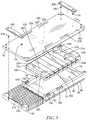
- FIG. 2is an exploded assembly view of the major components of the mattress of FIG. 1 ;
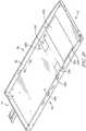
- FIG. 3is a detailed exploded assembly view of the mattress of FIG. 1 with portions omitted, the matter being inverted in FIG. 3 and illustrating the manner in which the components of the mattress are secured together to control movement of the mattress components during movement of various members of the bed frame;
- FIG. 4is an enlarged view of the portion of FIG. 3 enclosed in a circle
- FIG. 5is and assembly view of a bladder assembly of the mattress of FIG. 1 ;
- FIG. 6is a top plan view of the bladder assembly of FIG. 5 ;
- FIG. 7is right side view of the bladder assembly of FIG. 5 ;
- FIG. 8is a left side view of the bladder assembly of FIG. 5 , the bladder assembly being inverted in FIG. 8 ;
- FIG. 9is a plan view of a bladder of the bladder assembly of FIG. 5 ;
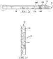
- FIG. 10is a side view of a bladder of the bladder assembly of FIG. 5 with portions cut-away to show a foam structure within the bladder;
- FIG. 11is a side view of another bladder of the bladder assembly of FIG. 5 with portions cut-away to show a foam structure within the bladder, the foam structure of FIG. 11 being different than the foam structure of FIG. 10 ;
- FIG. 12is an exploded assembly view of a foam frame of the mattress of FIG. 1 ;
- FIG. 13is a right side view of a core of the mattress of FIG. 1 ;
- FIG. 14is a top plan view of a portion of a perforated foot section of the foam frame of the mattress of FIG. 1 ;
- FIG. 15is a top plan view of the perforated foot section of the foam frame of the mattress of FIG. 1 ;
- FIG. 16is a right side view of the perforated foot section of the foam frame of the mattress of FIG. 1 ;
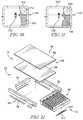
- FIG. 17is a perspective view of a knob that extends from a bottom cover of the mattress of FIG. 1 , the knob being configured to engage openings in deck members of the bed frame;
- FIG. 18is an illustration of an opening formed in a head deck of the bed frame of FIG. 1 , the opening configured to receive the knob of FIG. 17 ;
- FIG. 19is an illustration of an opening formed in a foot deck of the bed frame of FIG. 1 , the opening configured to receive the knob of FIG. 17 ;
- FIG. 20is a perspective view of the lower cover of the mattress of FIG. 1 .
- a patient support apparatus 10is illustratively embodied as a hospital bed 10 .
- the view shown in FIG. 1is generally taken from a position that is oriented at the left side, foot end of the hospital bed 10 .
- the discussion of the hospital bed 10will be based on the orientation of a patient supported on the hospital bed 10 in a supine position.
- the foot end 12 of the hospital bed 10refers to the end nearest the patient's feet when the patient is supported on the hospital bed 10 in the supine position.
- the hospital bed 10has a head end 14 opposite the foot end 12 .
- a left side 16refers to the patient's left when the patient is lying in the hospital bed 10 in a supine position.
- the right side 18refers to the patient's right. When reference is made to the longitudinal length of the hospital bed 10 , it refers a direction that is represented by the lines that generally extend between the head end 14 and foot end 12 of the hospital bed 10 . Similarly, lateral width of the hospital bed 10 refers to a direction that is represented by the lines that generally extend between the left side 16 and right side 18 .
- the hospital bed 10includes a base frame 20 which supports a lift system 22 .
- the lift system 22engages the base and an upper frame 24 such that the lift system 22 moves the upper frame 24 vertically relative to the base frame 20 .
- the lift system 22includes a head end linkage 27 and a foot end linkage 29 .
- Each of the linkages 27 and 29are independently operable and may be operated to cause the hospital bed 10 to move into a tilt position which is when the head end 14 of the upper frame 24 is positioned lower than the foot end 12 of the upper frame 24 .
- the hospital bed 10may also be moved to a reverse tilt position with the foot end 12 of the upper frame 24 is positioned lower than the head end 14 of the upper frame 24 .
- the upper frame 24supports a load frame 26 .
- the load frame 26supports a head deck 28 which is movable relative to the load frame 26 .
- the load frame 26also supports an articulated seat deck 30 , also movable relative to the load frame 26 and a fixed seat deck 32 .
- a foot deck 34that is articulated and moveable relative to the load frame 26 .
- the foot deck 34 in the illustrative embodiment of FIG. 1provides for powered pivoting of the foot deck 34 and manual extension and retraction of the foot deck 34 to vary the length of the foot deck 34 .
- powered pivoting of the foot deck 34may be omitted and the related movement may be caused manually, or follow movement of the articulated seat deck 30 .
- extension and retraction of the foot deck 34may be powered by an actuator.
- the foot deck 34includes a first portion 36 and a second portion 38 , which moves relative to the first portion 36 to vary the size of the foot deck 34 .
- the second portion 38moves generally longitudinally relative to the first portion 36 to vary the longitudinal length of the foot deck 34 and, thereby, the longitudinal length of the hospital bed 10 .
- a foot panel 40is supported from the second portion 38 and extends vertically from an upper surface 42 of the second portion 38 to form a barrier at the foot end 12 of the hospital bed 10 .
- a head panel 44is positioned on an upright structure 46 of the base frame 20 and extends vertically to form a barrier at the head end 14 of the hospital bed 10 .
- a left head siderail 48is supported from the head deck 28 and is moveable between a raised position shown in FIG. 1 and a lowered position as is known in the art.
- a right head siderail 50is also moveable between the raised position of FIG. 1 and lowered position. As shown in FIG.
- the siderails 48 and 50in the raised position, extend above an upper surface 52 of a mattress 54 of the hospital bed 10 when the siderails 48 and 50 are in a raised position. In a lowered position an upper edge 56 of the left head siderail 48 is below the upper surface 52 .
- the hospital bed 10also includes a left foot siderail 58 and a right foot siderail 60 , each of which is supported directly from the load frame 26 .
- Each of the siderails 48 , 50 , 58 , and 60are operable to be lowered to a position below the upper surface 52 . It should be noted that when the head deck 28 is moved, the head siderails 48 and 50 move with the head deck 28 so that they maintain their relative position to the patient. This is because both of the head siderails 48 and 50 are supported by the head deck 28 .
- the mattress 54includes a core 68 which comprises a bladder assembly 70 which engages a foam frame 72 .
- the foam frame 72includes a perforated foot support 62 which is coupled to a pair of longitudinal bolsters 74 and 76 .
- the longitudinal bolsters 74 , 76are interconnected by a header 78 which extends laterally between the bolsters 74 , 76 at the head end 14 of the mattress 54 .
- the core 68also includes an upper layer of foam 64 and a lower layer of foam 66 which are glued together to form an upper foam support 65 .
- the longitudinal bolsters 74 and 76are secured to the perforated foot support 62 such that the foot support 62 , bolsters 74 and 76 , header 78 , and foam support 65 cooperate to define a space 80 into which the bladder assembly 70 is positioned to form the core 68 .
- the mattress 54includes a lower cover 82 and an upper cover 84 which are secured together with a zipper as is known in the art.
- the mattress 54further includes a fire barrier assembly 126 which is wrapped over the top of core 68 to fully enclose the core 68 in the fire barrier assembly 126 .
- the bladder assembly 70includes eight bladders 96 , 98 , 100 , 102 , 104 , 106 , 107 , and 108 .
- the bladdersare arranged with bladder 108 positioned at the foot end 12 of the bladder assembly 70 and bladder 96 positioned at the head end 14 .
- Each bladder 96 , 98 , 100 , 102 , 104 , 106 , 107 , and 108comprises an outer enclosure 110 of urethane coated nylon which provides an air impermeable enclosure.
- inside of each enclosure 110is a two layered foam structure.
- the foam structure 112includes an upper layer 114 and a lower layer 116 .
- the foam layers 114 and 116are glued together.
- the foam structure 112is deformable under load, but resiliently expands to fill the interior space of the enclosure 110 .
- a different foam structure 142includes an upper layer 144 glued to a lower layer 146 .
- the foam materials used in layers 144 and 146differs from the layers 114 and 146 so that the foam structures 142 and 112 have different performance characteristics.
- the bladders 96 , 98 , and 100include the foam structure 112 while the bladders 102 , 104 , 106 , 107 , and 108 include the foam structure 142 .
- each of the enclosures 110is formed to include a transparent window 148 formed in wall 150 of the enclosure 110 .
- the window 148is positioned to overlie the interface between layers 114 and 116 or layers 144 and 146 so that a user may see the material within the enclosure 110 . This allows a user to distinguish the contents of the enclosure 110 to determine which of the foam structures 112 or 142 is included in the enclosure 110 .
- at least one of the upper layers 114 or 144 , or one of the lower layers 116 or 146is a different color.
- an assemblercan identify the characteristics of the particular enclosure 110 to determine whether the particular bladder should be positioned in the head portion as one of the bladders 96 , 98 , and 100 or the torso portion as one of the bladders 102 , 104 , 106 , 107 , and 108 .
- each enclosure 110At the left side 16 of each enclosure 110 is a pressure relief or check valve 118 .
- Each of the check valves 118are configured to open when the pressure applied to the valve exceeds the relief pressure of the valve 118 .
- the valves 118are arranged such that when the pressure inside any one of the enclosures 110 is lower than the pressure of atmosphere, the corresponding valve 118 opens to permit air to flow from atmosphere into the respective enclosure 110 .
- the mattress 54is self-adjusting to maintain the pressure within each of the bladders 96 , 98 , 100 , 102 , 104 , 106 , 107 , and 108 to a pressure below the relief pressure of the check valve 124 .
- the operation of the inlet valves 118 of any particular bladder 96 , 98 , 100 , 102 , 104 , 106 , 107 , and 108which is unloaded, provides for the rapid filling of the respective bladder 96 , 98 , 100 , 102 , 104 , 106 , 107 , and 108 with air from atmosphere.
- This approachhelps to regulate the pressure within the various bladders 96 , 98 , 100 , 102 , 104 , 106 , 107 , and 108 relatively quickly to control the support pressure experienced by a patient.
- venting of the pressure in the manifold tube 122 and pressure check valve 124permits the patient to be supported on the foam structures 112 of each bladder 96 , 98 , 100 , 102 , 104 , 106 , 107 , and 108 .
- the mattress 54provides the benefits of a pneumatic mattress with safety for larger patients from bottoming out against the surface of the decks of the hospital bed 10 .
- the foam structures 112also serve the purpose of expanding the enclosures 110 to create the vacuum which draws air through the valves 118 when a particular bladder 96 , 98 , 100 , 102 , 104 , 106 , 107 , and 108 is unloaded.
- foam structures 112 and 142have similar constructions. However, in some embodiments the layers 114 , 116 or 144 , 146 of the foam structures 112 and 142 , respectively, may have different properties in different bladders 96 , 98 , 100 , 102 , 104 , 106 , 107 , and 108 . In addition, the foam structures 112 , 142 may be a single layer, or may include more than two layers in some embodiments.
- each of the longitudinal bolsters 74 , 76are formed to include a series of relief slits 128 positioned at the location in the longitudinal bolsters 74 , 76 which are positioned at the intersection of the head deck 28 and the articulated seat deck 30 .
- the relief slits 128provide for expansion of the longitudinal bolsters 74 , 76 when the head deck 28 is raised. With the relief slits 128 , little material is removed, but the foam is permitted to expand at the location of the slits 128 .
- a series of cutouts 130are positioned at the interface between the articulated seat deck 30 and the foot deck 34 .
- the cutouts 130are generally triangular with more material removed at a lower surface 132 of the longitudinal bolsters 74 , 76 , the cutouts 130 becoming narrower to a termination spaced apart from the lower surface 132 .
- the cutouts 130provide for both expansion and collapsing of the length of the longitudinal bolsters 74 , 76 at the interface between the articulated seat deck 30 and the foot deck 34 .
- the removed material at the surface 132permits the cutouts 130 to collapse when the foot deck 34 is moved downwardly relative to the articulated seat deck 30 such that the material of the longitudinal bolsters 74 , 76 does not bulge.
- the bladders 96 , 98 , 100 , 102 , 104 , 106 , 107 , and 108are each positioned in a respective sleeve 156 , 158 , 160 , 162 , 164 , 166 , 168 , and 170 of a cover 172 .
- the cover 172is formed of a fabric that is sewn to form the sleeves 156 , 158 , 160 , 162 , 164 , 166 , 168 , and 170 as a unitary structure so that the bladders 96 , 98 , 100 , 102 , 104 , 106 , 107 , and 108 are permitted some relative movement, but the cover 172 maintains the relationship between the bladders 96 , 98 , 100 , 102 , 104 , 106 , 107 , and 108 during compound articulation of the frame and deck members of the bed 10 . This prevents the bladders 96 , 98 , 100 , 102 , 104 , 106 , 107 , and 108 from becoming dislodged and maintains an appropriate orientation.
- knobs 174 , 176 , 178 , and 180extend from a bottom surface 182 of the lower cover 82 as shown in FIG. 3 .
- the knobs 174 , 176 , 178 , and 180are similarly arranged and details of knob 174 are shown in FIG. 17 and the knob 174 includes a spherical body 182 that is coupled to a stem 184 that extends from a base 186 .
- the head deck 28is formed to include a slotted opening 188 as shown in FIG. 18 .
- the slotted opening 188is formed with a key-hole effect so that a wider portion 190 narrows to a thin portion 192 .
- the slotted opening 188has a longitudinal axis 194 that extends laterally on the deck 28 with the slotted opening positioned with the wider portion positioned on the outboard side of the deck 28 .
- a second slotted opening that is a mirror image of the slotted opening 188is positioned on the opposite outboard side of the deck so that the knob 178 is positioned in the slotted opening 188 and the knob 180 is positioned in the mirror image slot. The natural tendency is to have the knobs 178 and 188 to be urged into the narrow portion 192 of each of the slotted openings.
- Another configuration of key-hole opening 196is positioned in the second portion 38 of deck 34 through the surface 42 as shown in FIG. 19 .
- a circular opening 198is positioned nearer the foot end 12 of the second portion 38 and the knobs 174 and 176 are each received in a circular opening 198 of a respective key-hole opening 196 so that the stem 184 is urged into a slot 200 .
- the knobs 174 , 176 , 178 , and 180are engaged with the deck 28 and deck 34 respectively, movement of the decks 28 , 30 , and 34 are transferred directly to the mattress 54 such that the mattress 54 moves with the decks 28 , 30 , and 34 .
- the knobs 174 and 176are secured to a plate 202 , seen in FIG. 3 , that is glued to the foot end 12 of the perforated foot support 62 by a nut 204 and washer 206 (seen in FIG. 4 ) with the nut 204 being received on a threaded stem 208 of the knobs 174 and 176 .
- the plate 202is positioned in a sleeve 210 (seen in FIG. 14 ) that is glued to the perforated foot support 62 .
- the plate 202is free to move in the sleeve 210 in the direction of the arrow 212 as necessary.
- the knobs 178 and 180are secured to respective plates 214 and 216 shown in FIG. 3 .
- the cover 172is formed to include a flap 218 with the plates 214 and 216 being secured to the flap 218 when the knobs 178 and 180 are secured by the respective nuts 204 .
- the plates 214 , 216 and flap 218cooperate to permit controlled movement of the bladder assembly 70 relative to the lower cover 82 .
- the bladder assembly 70is further secured to the lower cover 82 by a plate 220 positioned in a sleeve 222 formed on the bottom of sleeve 170 of the cover 172 of the bladder assembly 70 .
- the plate 220includes two flanges 224 , 226 which are received in pockets 228 and 230 respectively.
- the pockets 228 and 230are formed in the lower cover 82 by welding flaps of material 232 , 234 to the upper surface 236 of the lower cover 82 .
- the plate 220is flexible so that the flanges 224 , 226 can be slipped under the flaps 232 , 234 into the pockets 228 , 230 .
- the bladder assembly 70is secured to the lower cover 82 at the head end 14 by the plates 214 , 216 and knobs 178 , 180 and the foot end 12 of the bladder assembly 70 is secured to the lower cover 82 with the flanges 224 , 226 positioned in the pockets 228 , 230 .
- the overall mattress 54is secured by the knobs 174 , 176 , 178 , 180 , while the bladder assembly 70 is maintained in position by the flanges 224 , 226 positioned in the pockets 228 , 230 in cooperation with the plates 214 , 216 and knobs 178 , 180 .
- the perforated foot section 62is free to expand and contract relative to the bladder assembly 70 when the second portion 38 of the deck 34 moves relative to the first portion 36 . This helps control the location of the perforated foot section 62 and the bladder assembly 70 onto the appropriate portions of the decks 28 , 30 , 32 , and 34 . Referring now to FIG.
- a flap 238 of fabricis welded to the surface 236 of cover 82 so that a pocket 240 is formed in the area of the cover 82 underlying a portion of the perforated foot section 62 .
- the pocket 240receives a plate 242 that is positioned therein and serves to stiffen the portion of the lower cover 82 that overlies the interface between the first portion 36 and second portion 38 of the deck 34 . This prevents bunching of the lower cover 82 during movement interface between the first portion 36 and second portion 38 of the deck 34 .
- the relative movement of deck 30 and deck 34 , the interface between the perforated foot section 62 and the bladder assembly 70is subject to being flexed. This flexing must be accommodated without bunching of the foam members at the interface.
- the perforated foot section 62comprises relatively soft foam that provides relief to the heels of a patient positioned on the mattress 54 .
- the foam structures 112 and 142are relatively stiff to provide support for the patient's seat and torso. Referring to FIGS.
- the perforated foot section 62is modified to include a foam block 244 that is positioned under a cantilevered member 246 that extends from the perforated body 248 of the perforated foot section 62 .
- the foam block 244has a density that provides a stiffness that exceeds the stiffness of the material of the body 248 and cantilevered member 246 .
- the foam block 244is formed with material removed so that the bolsters 74 , 76 cooperate with the foam block to form a rabbet joint.
- the cantilevered member 246overlaps the bolsters 74 , 76 to provide a uniform upper surface 250 .
- the lower cover 82includes a number of structures formed on the lower surface 182 including four linen lock straps 270 , 272 , 274 , and 276 positioned at the four corners.
- the linen lock straps 270 , 272 , 274 , and 276are a urethane coated nylon fabric that is sewn to a substrate fabric 286 of the lower cover 82 at each end of the respective strap 270 , 272 , 274 , and 276 .
- the straps 270 , 272 , 274 , and 276are configured to allow a user to tuck a corner of a linen, such as a sheet, for example into the strap 270 , 272 , 274 , or 276 to secure the linen under the mattress 54 .
- four handles 278 , 280 , 282 , and 284are sewn to the substrate and are positioned to allow a user to carry the mattress 54 .
- Two travel guards, 288 and 290are positionable over the knobs 174 , 176 and 178 , 180 , respectively.
- the travel guards 288 and 290comprise foam and are removably secured to the knobs 174 , 176 and 178 , 180 , respectively to cover the knobs 174 , 176 , 178 , and 180 to prevent damage to the knobs 174 , 176 , 178 , and 180 during transport of the mattress 54 .
Landscapes
- Health & Medical Sciences (AREA)
- Nursing (AREA)
- Life Sciences & Earth Sciences (AREA)
- Animal Behavior & Ethology (AREA)
- General Health & Medical Sciences (AREA)
- Public Health (AREA)
- Veterinary Medicine (AREA)
- Rehabilitation Therapy (AREA)
- Invalid Beds And Related Equipment (AREA)
- Mattresses And Other Support Structures For Chairs And Beds (AREA)
Abstract
Description
Claims (19)
Priority Applications (4)
| Application Number | Priority Date | Filing Date | Title |
|---|---|---|---|
| US16/038,253US11033117B2 (en) | 2017-07-27 | 2018-07-18 | Dynamic foam mattress adapted for use with a variable length hospital bed |
| EP21169221.5AEP3892248B1 (en) | 2017-07-27 | 2018-07-26 | Dynamic foam mattress adapted for use with a variable length hospital bed |
| EP18185828.3AEP3434246B1 (en) | 2017-07-27 | 2018-07-26 | Dynamic foam mattress adapted for use with a variable length hospital bed |
| US17/347,078US11969100B2 (en) | 2017-07-27 | 2021-06-14 | Dynamic foam mattress adapted for use with a variable length hospital bed |
Applications Claiming Priority (2)
| Application Number | Priority Date | Filing Date | Title |
|---|---|---|---|
| US201762537943P | 2017-07-27 | 2017-07-27 | |
| US16/038,253US11033117B2 (en) | 2017-07-27 | 2018-07-18 | Dynamic foam mattress adapted for use with a variable length hospital bed |
Related Child Applications (1)
| Application Number | Title | Priority Date | Filing Date |
|---|---|---|---|
| US17/347,078ContinuationUS11969100B2 (en) | 2017-07-27 | 2021-06-14 | Dynamic foam mattress adapted for use with a variable length hospital bed |
Publications (2)
| Publication Number | Publication Date |
|---|---|
| US20190029439A1 US20190029439A1 (en) | 2019-01-31 |
| US11033117B2true US11033117B2 (en) | 2021-06-15 |
Family
ID=63077796
Family Applications (2)
| Application Number | Title | Priority Date | Filing Date |
|---|---|---|---|
| US16/038,253Active2039-08-14US11033117B2 (en) | 2017-07-27 | 2018-07-18 | Dynamic foam mattress adapted for use with a variable length hospital bed |
| US17/347,078Active2039-08-31US11969100B2 (en) | 2017-07-27 | 2021-06-14 | Dynamic foam mattress adapted for use with a variable length hospital bed |
Family Applications After (1)
| Application Number | Title | Priority Date | Filing Date |
|---|---|---|---|
| US17/347,078Active2039-08-31US11969100B2 (en) | 2017-07-27 | 2021-06-14 | Dynamic foam mattress adapted for use with a variable length hospital bed |
Country Status (2)
| Country | Link |
|---|---|
| US (2) | US11033117B2 (en) |
| EP (2) | EP3434246B1 (en) |
Cited By (1)
| Publication number | Priority date | Publication date | Assignee | Title |
|---|---|---|---|---|
| US20210298488A1 (en)* | 2017-07-27 | 2021-09-30 | Hill-Rom Services, Inc. | Dynamic foam mattress adapted for use with a variable length hospital bed |
Families Citing this family (4)
| Publication number | Priority date | Publication date | Assignee | Title |
|---|---|---|---|---|
| GB2569281B (en)* | 2017-11-03 | 2022-04-06 | Zommos Holdings Ltd | Mattress interior, mattress and method of manufacturing a mattress |
| US11389120B2 (en)* | 2019-05-30 | 2022-07-19 | Hill-Rom Services, Inc. | Mattress having selectable patient weight valve, inductive power, and a digital x-ray cassette |
| GB2608796B (en)* | 2021-07-02 | 2024-07-31 | James Leckey Design Ltd | Extendable postural support cushion |
| US12036163B2 (en)* | 2022-05-17 | 2024-07-16 | Briizzz LLC | Positive pressure support device |
Citations (36)
| Publication number | Priority date | Publication date | Assignee | Title |
|---|---|---|---|---|
| US4644597A (en) | 1983-05-09 | 1987-02-24 | Dynatech, Inc. | Air mattress with pressure relief valve |
| US4679264A (en) | 1985-05-06 | 1987-07-14 | Mollura Carlos A | Airbed mattress including a regulated, controllable air reservoir therefor |
| US5142717A (en) | 1988-10-20 | 1992-09-01 | Sustena, Inc. | Constant pressure load bearing air chamber |
| US5634224A (en) | 1994-08-16 | 1997-06-03 | Gates; Stephen M. | Inflatable cushioning device with self opening intake valve |
| US5652985A (en) | 1994-06-03 | 1997-08-05 | Span-America Medical Systems, Inc. | Self-adjusting pressure relief support system and methodology |
| US5699570A (en) | 1996-06-14 | 1997-12-23 | Span-America Medical Systems, Inc. | Pressure relief valve vent line mattress system and method |
| WO2002038099A2 (en) | 2000-11-07 | 2002-05-16 | Tempur World, Inc. | Therapeutic mattress assembly |
| US20020116766A1 (en) | 2001-02-15 | 2002-08-29 | Stolpmann James R. | Self-inflating mattress |
| US6564411B2 (en) | 2001-03-19 | 2003-05-20 | Shahzad Pirzada | Active fluid channeling system for a bed |
| US6611979B2 (en) | 1997-09-23 | 2003-09-02 | Hill-Rom Services, Inc. | Mattress having a retractable foot section |
| US6684434B2 (en) | 1999-07-06 | 2004-02-03 | Hill-Rom Services, Inc. | Mattress assembly |
| US20040222684A1 (en) | 2002-11-22 | 2004-11-11 | Schukra Of North America | Self inflating pneumatic seat cushion apparatus and method |
| US20050125905A1 (en) | 1999-04-20 | 2005-06-16 | John Wilkinson | Inflatable cushioning device with manifold system |
| US20050177952A1 (en) | 2004-02-13 | 2005-08-18 | Wilkinson John W. | Discrete cell body support and method for using the same to provide dynamic massage |
| US20060026765A1 (en)* | 2004-07-30 | 2006-02-09 | Hornbach David W | Advanced articulation system and mattress support for a bed |
| US7213279B2 (en) | 1995-08-04 | 2007-05-08 | Weismiller Matthew W | Hospital bed and mattress having extendable foot section |
| WO2007095263A2 (en) | 2006-02-10 | 2007-08-23 | Scott Technology Llc | Self inflating air mattress |
| US20080028534A1 (en) | 1999-04-20 | 2008-02-07 | M.P.L. Limited | Mattress having three separate adjustable pressure relief zones |
| US7520006B2 (en) | 2002-09-06 | 2009-04-21 | Hill-Rom Services, Inc. | Hospital bed including moveable foot portion |
| US20100090383A1 (en)* | 2006-08-29 | 2010-04-15 | Rawls-Meehan Martin B | Distinguishing different firmness foam springs and alternatives for foam spring end caps |
| WO2010058158A1 (en) | 2008-11-18 | 2010-05-27 | Psp Technology Limited | Pneumatic mattress |
| US20100146709A1 (en) | 2008-12-17 | 2010-06-17 | Stryker Corporation | Patient support |
| US7886386B2 (en)* | 2005-03-28 | 2011-02-15 | Bg Industries, Llc. | Mattress |
| US20120065560A1 (en) | 2010-09-15 | 2012-03-15 | Kenneth Scott Siegner | Support surface system providing simultaneous alternating pressure and low air loss therapies |
| US20120144595A1 (en)* | 2010-12-08 | 2012-06-14 | Hornbach David W | Mattress deflation management |
| US8286282B2 (en) | 1995-08-04 | 2012-10-16 | Hill-Rom Services, Inc. | Bed frame and mattress synchronous control |
| US20130019409A1 (en) | 2011-07-19 | 2013-01-24 | Jiajing Usa, Inc. | Comfort customizable pillow |
| US20130219626A1 (en) | 2010-11-01 | 2013-08-29 | Roho, Inc. | Cushion and self-adjusting valve |
| WO2013164687A1 (en) | 2012-05-03 | 2013-11-07 | Linet Spol. S.R.O. | Pneumatic mattress |
| US20130340168A1 (en) | 2012-06-21 | 2013-12-26 | Hill-Rom Services, Inc. | Patient support systems and methods of use |
| WO2014080196A2 (en) | 2012-11-22 | 2014-05-30 | Direct Healthcare Services Ltd | Mattress arrangement |
| US20140259432A1 (en) | 2013-03-14 | 2014-09-18 | Kap Medical, Inc. | Patient support apparatus and method |
| US9271579B2 (en) | 2013-04-05 | 2016-03-01 | Rapid Air Llc | Adjustable mattress with foam inserts and air chambers |
| US9820904B2 (en) | 2011-07-13 | 2017-11-21 | Stryker Corporation | Patient/invalid handling support |
| US20180064593A1 (en)* | 2012-06-21 | 2018-03-08 | Hill-Rom Services, Inc. | Mattress bladder control during patient bed egress |
| US10182954B2 (en) | 2014-09-08 | 2019-01-22 | Wcw, Inc. | Cushioning device and method |
Family Cites Families (2)
| Publication number | Priority date | Publication date | Assignee | Title |
|---|---|---|---|---|
| US7469436B2 (en)* | 2004-04-30 | 2008-12-30 | Hill-Rom Services, Inc. | Pressure relief surface |
| US11033117B2 (en)* | 2017-07-27 | 2021-06-15 | Hill-Rom Services, Inc. | Dynamic foam mattress adapted for use with a variable length hospital bed |
- 2018
- 2018-07-18USUS16/038,253patent/US11033117B2/enactiveActive
- 2018-07-26EPEP18185828.3Apatent/EP3434246B1/enactiveActive
- 2018-07-26EPEP21169221.5Apatent/EP3892248B1/enactiveActive
- 2021
- 2021-06-14USUS17/347,078patent/US11969100B2/enactiveActive
Patent Citations (41)
| Publication number | Priority date | Publication date | Assignee | Title |
|---|---|---|---|---|
| US4644597A (en) | 1983-05-09 | 1987-02-24 | Dynatech, Inc. | Air mattress with pressure relief valve |
| US4679264A (en) | 1985-05-06 | 1987-07-14 | Mollura Carlos A | Airbed mattress including a regulated, controllable air reservoir therefor |
| US5142717A (en) | 1988-10-20 | 1992-09-01 | Sustena, Inc. | Constant pressure load bearing air chamber |
| US5652985A (en) | 1994-06-03 | 1997-08-05 | Span-America Medical Systems, Inc. | Self-adjusting pressure relief support system and methodology |
| US5634224A (en) | 1994-08-16 | 1997-06-03 | Gates; Stephen M. | Inflatable cushioning device with self opening intake valve |
| US7213279B2 (en) | 1995-08-04 | 2007-05-08 | Weismiller Matthew W | Hospital bed and mattress having extendable foot section |
| US8286282B2 (en) | 1995-08-04 | 2012-10-16 | Hill-Rom Services, Inc. | Bed frame and mattress synchronous control |
| US5699570A (en) | 1996-06-14 | 1997-12-23 | Span-America Medical Systems, Inc. | Pressure relief valve vent line mattress system and method |
| US6611979B2 (en) | 1997-09-23 | 2003-09-02 | Hill-Rom Services, Inc. | Mattress having a retractable foot section |
| US20080028534A1 (en) | 1999-04-20 | 2008-02-07 | M.P.L. Limited | Mattress having three separate adjustable pressure relief zones |
| US20050125905A1 (en) | 1999-04-20 | 2005-06-16 | John Wilkinson | Inflatable cushioning device with manifold system |
| US6684434B2 (en) | 1999-07-06 | 2004-02-03 | Hill-Rom Services, Inc. | Mattress assembly |
| US20140310881A1 (en)* | 2000-11-07 | 2014-10-23 | Tempur-Pedic Management, Llc | Therapeutic mattress assembly |
| WO2002038099A2 (en) | 2000-11-07 | 2002-05-16 | Tempur World, Inc. | Therapeutic mattress assembly |
| US6694556B2 (en) | 2001-02-15 | 2004-02-24 | Hill-Rom Services, Inc. | Self-inflating mattress |
| US20020116766A1 (en) | 2001-02-15 | 2002-08-29 | Stolpmann James R. | Self-inflating mattress |
| US6564411B2 (en) | 2001-03-19 | 2003-05-20 | Shahzad Pirzada | Active fluid channeling system for a bed |
| US7520006B2 (en) | 2002-09-06 | 2009-04-21 | Hill-Rom Services, Inc. | Hospital bed including moveable foot portion |
| US20040222684A1 (en) | 2002-11-22 | 2004-11-11 | Schukra Of North America | Self inflating pneumatic seat cushion apparatus and method |
| US7434283B2 (en) | 2004-02-13 | 2008-10-14 | M.P.L. Limited | Discrete cell body support and method for using the same to provide dynamic massage |
| US20050177952A1 (en) | 2004-02-13 | 2005-08-18 | Wilkinson John W. | Discrete cell body support and method for using the same to provide dynamic massage |
| US20060026765A1 (en)* | 2004-07-30 | 2006-02-09 | Hornbach David W | Advanced articulation system and mattress support for a bed |
| US7886386B2 (en)* | 2005-03-28 | 2011-02-15 | Bg Industries, Llc. | Mattress |
| US8261387B2 (en)* | 2006-02-10 | 2012-09-11 | Joerns Llc | Self inflating air mattress |
| WO2007095263A2 (en) | 2006-02-10 | 2007-08-23 | Scott Technology Llc | Self inflating air mattress |
| US20100090383A1 (en)* | 2006-08-29 | 2010-04-15 | Rawls-Meehan Martin B | Distinguishing different firmness foam springs and alternatives for foam spring end caps |
| WO2010058158A1 (en) | 2008-11-18 | 2010-05-27 | Psp Technology Limited | Pneumatic mattress |
| US20100146709A1 (en) | 2008-12-17 | 2010-06-17 | Stryker Corporation | Patient support |
| US20120065560A1 (en) | 2010-09-15 | 2012-03-15 | Kenneth Scott Siegner | Support surface system providing simultaneous alternating pressure and low air loss therapies |
| US20130219626A1 (en) | 2010-11-01 | 2013-08-29 | Roho, Inc. | Cushion and self-adjusting valve |
| US20120144595A1 (en)* | 2010-12-08 | 2012-06-14 | Hornbach David W | Mattress deflation management |
| US9820904B2 (en) | 2011-07-13 | 2017-11-21 | Stryker Corporation | Patient/invalid handling support |
| US20130019409A1 (en) | 2011-07-19 | 2013-01-24 | Jiajing Usa, Inc. | Comfort customizable pillow |
| US9314118B2 (en) | 2011-07-19 | 2016-04-19 | Jiajing Usa, Inc. | Comfort customizable pillow |
| WO2013164687A1 (en) | 2012-05-03 | 2013-11-07 | Linet Spol. S.R.O. | Pneumatic mattress |
| US20130340168A1 (en) | 2012-06-21 | 2013-12-26 | Hill-Rom Services, Inc. | Patient support systems and methods of use |
| US20180064593A1 (en)* | 2012-06-21 | 2018-03-08 | Hill-Rom Services, Inc. | Mattress bladder control during patient bed egress |
| WO2014080196A2 (en) | 2012-11-22 | 2014-05-30 | Direct Healthcare Services Ltd | Mattress arrangement |
| US20140259432A1 (en) | 2013-03-14 | 2014-09-18 | Kap Medical, Inc. | Patient support apparatus and method |
| US9271579B2 (en) | 2013-04-05 | 2016-03-01 | Rapid Air Llc | Adjustable mattress with foam inserts and air chambers |
| US10182954B2 (en) | 2014-09-08 | 2019-01-22 | Wcw, Inc. | Cushioning device and method |
Non-Patent Citations (2)
| Title |
|---|
| European Search Report, Application No. EP18185828.3-1113, dated Dec. 20, 2018, 9 pages. |
| Official Action in related CN201810847857.5, dated Jul. 30, 2020, 8 pages. |
Cited By (2)
| Publication number | Priority date | Publication date | Assignee | Title |
|---|---|---|---|---|
| US20210298488A1 (en)* | 2017-07-27 | 2021-09-30 | Hill-Rom Services, Inc. | Dynamic foam mattress adapted for use with a variable length hospital bed |
| US11969100B2 (en)* | 2017-07-27 | 2024-04-30 | Hill-Rom Services, Inc. | Dynamic foam mattress adapted for use with a variable length hospital bed |
Also Published As
| Publication number | Publication date |
|---|---|
| EP3892248B1 (en) | 2024-11-13 |
| EP3434246A1 (en) | 2019-01-30 |
| US20190029439A1 (en) | 2019-01-31 |
| EP3434246B1 (en) | 2021-05-26 |
| US20210298488A1 (en) | 2021-09-30 |
| US11969100B2 (en) | 2024-04-30 |
| EP3892248A1 (en) | 2021-10-13 |
Similar Documents
| Publication | Publication Date | Title |
|---|---|---|
| US11969100B2 (en) | Dynamic foam mattress adapted for use with a variable length hospital bed | |
| US6868569B2 (en) | Reversed air mattress | |
| US8225444B2 (en) | Inflatable device forming mattresses and cushions | |
| US7360266B2 (en) | Multiple position air mattress system | |
| US7424760B2 (en) | Body support, comfort device | |
| US9750655B2 (en) | Conformable support system | |
| US20110047709A1 (en) | Support device with adjustable length and width | |
| JPH06500943A (en) | Zoned compartment cushion with flexible flap housing inflatable manifold | |
| US6282735B1 (en) | Hydrotherapy bed | |
| US20070234480A1 (en) | Air mattress for bed with step deck | |
| US10058190B1 (en) | Air-foam mattress component | |
| JP7374146B2 (en) | Dynamic foam mattress suitable for use on hospital beds with varying lengths | |
| GB2577323A (en) | Segmented foam cushion |
Legal Events
| Date | Code | Title | Description |
|---|---|---|---|
| FEPP | Fee payment procedure | Free format text:ENTITY STATUS SET TO UNDISCOUNTED (ORIGINAL EVENT CODE: BIG.); ENTITY STATUS OF PATENT OWNER: LARGE ENTITY | |
| STPP | Information on status: patent application and granting procedure in general | Free format text:DOCKETED NEW CASE - READY FOR EXAMINATION | |
| AS | Assignment | Owner name:HILL-ROM SERVICES, INC., INDIANA Free format text:ASSIGNMENT OF ASSIGNORS INTEREST;ASSIGNORS:WAGNER, CATHERINE;BORGMAN, DARRELL;PELO, TRAVIS;AND OTHERS;SIGNING DATES FROM 20180802 TO 20190709;REEL/FRAME:049750/0536 | |
| AS | Assignment | Owner name:JPMORGAN CHASE BANK, N.A., ILLINOIS Free format text:SECURITY AGREEMENT;ASSIGNORS:HILL-ROM HOLDINGS, INC.;HILL-ROM, INC.;HILL-ROM SERVICES, INC.;AND OTHERS;REEL/FRAME:050260/0644 Effective date:20190830 | |
| STPP | Information on status: patent application and granting procedure in general | Free format text:NON FINAL ACTION MAILED | |
| STPP | Information on status: patent application and granting procedure in general | Free format text:RESPONSE TO NON-FINAL OFFICE ACTION ENTERED AND FORWARDED TO EXAMINER | |
| STPP | Information on status: patent application and granting procedure in general | Free format text:NOTICE OF ALLOWANCE MAILED -- APPLICATION RECEIVED IN OFFICE OF PUBLICATIONS | |
| STPP | Information on status: patent application and granting procedure in general | Free format text:PUBLICATIONS -- ISSUE FEE PAYMENT RECEIVED | |
| STPP | Information on status: patent application and granting procedure in general | Free format text:PUBLICATIONS -- ISSUE FEE PAYMENT VERIFIED | |
| STCF | Information on status: patent grant | Free format text:PATENTED CASE | |
| AS | Assignment | Owner name:HILL-ROM HOLDINGS, INC., ILLINOIS Free format text:RELEASE OF SECURITY INTEREST AT REEL/FRAME 050260/0644;ASSIGNOR:JPMORGAN CHASE BANK, N.A.;REEL/FRAME:058517/0001 Effective date:20211213 Owner name:BARDY DIAGNOSTICS, INC., ILLINOIS Free format text:RELEASE OF SECURITY INTEREST AT REEL/FRAME 050260/0644;ASSIGNOR:JPMORGAN CHASE BANK, N.A.;REEL/FRAME:058517/0001 Effective date:20211213 Owner name:VOALTE, INC., FLORIDA Free format text:RELEASE OF SECURITY INTEREST AT REEL/FRAME 050260/0644;ASSIGNOR:JPMORGAN CHASE BANK, N.A.;REEL/FRAME:058517/0001 Effective date:20211213 Owner name:HILL-ROM, INC., ILLINOIS Free format text:RELEASE OF SECURITY INTEREST AT REEL/FRAME 050260/0644;ASSIGNOR:JPMORGAN CHASE BANK, N.A.;REEL/FRAME:058517/0001 Effective date:20211213 Owner name:WELCH ALLYN, INC., NEW YORK Free format text:RELEASE OF SECURITY INTEREST AT REEL/FRAME 050260/0644;ASSIGNOR:JPMORGAN CHASE BANK, N.A.;REEL/FRAME:058517/0001 Effective date:20211213 Owner name:ALLEN MEDICAL SYSTEMS, INC., ILLINOIS Free format text:RELEASE OF SECURITY INTEREST AT REEL/FRAME 050260/0644;ASSIGNOR:JPMORGAN CHASE BANK, N.A.;REEL/FRAME:058517/0001 Effective date:20211213 Owner name:HILL-ROM SERVICES, INC., ILLINOIS Free format text:RELEASE OF SECURITY INTEREST AT REEL/FRAME 050260/0644;ASSIGNOR:JPMORGAN CHASE BANK, N.A.;REEL/FRAME:058517/0001 Effective date:20211213 Owner name:BREATHE TECHNOLOGIES, INC., CALIFORNIA Free format text:RELEASE OF SECURITY INTEREST AT REEL/FRAME 050260/0644;ASSIGNOR:JPMORGAN CHASE BANK, N.A.;REEL/FRAME:058517/0001 Effective date:20211213 | |
| MAFP | Maintenance fee payment | Free format text:PAYMENT OF MAINTENANCE FEE, 4TH YEAR, LARGE ENTITY (ORIGINAL EVENT CODE: M1551); ENTITY STATUS OF PATENT OWNER: LARGE ENTITY Year of fee payment:4 |