US11032197B2 - Reroute detection in segment routing data plane - Google Patents
Reroute detection in segment routing data planeDownload PDFInfo
- Publication number
- US11032197B2 US11032197B2US15/266,498US201615266498AUS11032197B2US 11032197 B2US11032197 B2US 11032197B2US 201615266498 AUS201615266498 AUS 201615266498AUS 11032197 B2US11032197 B2US 11032197B2
- Authority
- US
- United States
- Prior art keywords
- segment
- node
- message
- backup
- path
- Prior art date
- Legal status (The legal status is an assumption and is not a legal conclusion. Google has not performed a legal analysis and makes no representation as to the accuracy of the status listed.)
- Active
Links
Images


Classifications
- H—ELECTRICITY
- H04—ELECTRIC COMMUNICATION TECHNIQUE
- H04L—TRANSMISSION OF DIGITAL INFORMATION, e.g. TELEGRAPHIC COMMUNICATION
- H04L45/00—Routing or path finding of packets in data switching networks
- H04L45/74—Address processing for routing
- H04L45/745—Address table lookup; Address filtering
- H—ELECTRICITY
- H04—ELECTRIC COMMUNICATION TECHNIQUE
- H04L—TRANSMISSION OF DIGITAL INFORMATION, e.g. TELEGRAPHIC COMMUNICATION
- H04L45/00—Routing or path finding of packets in data switching networks
- H04L45/28—Routing or path finding of packets in data switching networks using route fault recovery
- H—ELECTRICITY
- H04—ELECTRIC COMMUNICATION TECHNIQUE
- H04L—TRANSMISSION OF DIGITAL INFORMATION, e.g. TELEGRAPHIC COMMUNICATION
- H04L69/00—Network arrangements, protocols or services independent of the application payload and not provided for in the other groups of this subclass
- H04L69/22—Parsing or analysis of headers
- H—ELECTRICITY
- H04—ELECTRIC COMMUNICATION TECHNIQUE
- H04W—WIRELESS COMMUNICATION NETWORKS
- H04W24/00—Supervisory, monitoring or testing arrangements
- H04W24/06—Testing, supervising or monitoring using simulated traffic
Definitions
- This disclosurerelates generally to networking and more particularly to detection of fast reroute occurrences.
- Network nodesforward data.
- Network nodesmay take the form of one or more routers, one or more bridges, one or more switches, one or more servers, or any other suitable communications processing device.
- the datais commonly formatted as messages and forwarded using forwarding tables.
- a messageis a formatted unit of data that typically contains control information and payload data.
- Control informationmay include information that identifies sources and destinations, such as addresses, error detection codes like checksums, sequencing information, etc. Control information is typically found in message headers and trailers.
- Payload datais typically located between the message headers and trailers.
- a messagemay be formatted and/or referred to as one of various specific types such as packets, datagrams, segments, or frames.
- FIG. 1is a simplified diagram illustrating certain components of an example network in which primary and secondary paths are allocated.
- FIG. 2is a simplified diagram illustrating use of test messages to check continuity of paths in the network of FIG. 1 .
- FIGS. 3A through 3Care tables illustrating exemplary forwarding table information.
- FIGS. 4A through 4Care tables illustrating exemplary forwarding table information for a network implementation including reroute protection.
- FIGS. 5A through 5Dare tables illustrating exemplary forwarding table information for a network implementation including detection of reroute protection use.
- FIGS. 6A and 6Bare simplified diagrams illustrating reroute of test messages in networks configured for reroute detection.
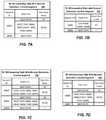
- FIGS. 7A through 7Dare tables illustrating exemplary forwarding table information for a network implementation configured for reroute detection using a backup context segment identifier.
- FIG. 8is a simplified network diagram illustrating reroute of test messages in a network configured for reroute detection using a backup context segment identifier.
- FIGS. 9A and 9Bare flowcharts illustrating examples of processes of preparing a network node for reroute detection.
- FIG. 10is a flowchart illustrating an example of a process of establishing test paths in a network.
- FIG. 11is a flowchart illustrating an example of a process of managing quality of paths in a network.
- FIG. 12is a flowchart illustrating an example of a process carried out by a node of a network described herein.
- FIG. 13is a simplified block diagram illustrating certain components of an example network device that can be employed in the networks described herein.
- FIG. 14is a simplified block diagram illustrating certain components of an example network device that can be employed in the networks described herein.
- FIG. 15is a simplified block diagram depicting a computer system suitable for implementing embodiments of the devices and systems described herein.
- a methodincludes receiving, at a first node in a communications network, a test message comprising a header, where the header comprises one or more segment identifiers. This embodiment of the method further includes detecting a first indicator of a rerouted test path for the message and sending an outgoing message to a node determined using the header, where sending the outgoing message comprises including in the outgoing message a second indicator that the test message has been rerouted.
- Routingis a process for forwarding network traffic (e.g., packets) to destinations.
- packet forwarding mechanismsinclude Internet Protocol (IP) routing and Multiprotocol Label Switching (MPLS).
- IP routinguses IP addresses inside packet headers to make forwarding decisions.
- MPLS nodesi.e., nodes employing MPLS
- MPLS nodescan make forwarding decisions using short path identifiers called labels that are attached to packets.
- Segment routingis yet another packet forwarding mechanism, in which packet forwarding decisions are based on short path identifiers called segment identifiers attached to packets.
- MPLS labels, segment identifiers, and other types of control informationmay be described as “attached to” a data packet, though this information is more accurately considered to be “put into” the packet, since control information, as well as the headers and trailers it appears in, is a part of the packet, along with the payload data.
- the labelsare included between the IP header and data link layer header of an IP packet, as discussed further below. “Attached to” or “added to” a packet as used herein with reference to routing labels or identifiers should be understood to indicate that the labels or identifiers are included within the packet.
- the data planealso referred to as the “forwarding plane,” does the actual forwarding of packets coming into a node.
- Data plane decisionsmay involve accessing a forwarding table that relates the appropriate packet identifier (such as an IP address or MPLS label) to the specific network interface, or egress interface, the packet should be sent to in order to send it in the right direction.
- Generating such a forwarding tablebased on a map, database, or other information reflecting the topology of the network, is a function of the control plane.
- the control planegenerates and updates its network topology information using one or more routing protocols.
- an interior gateway protocolIGP
- An autonomous system, or routing domain, as used hereinrefers to a collection of interconnected network nodes under a common administration for purposes of network configuration. Exchange of routing information between autonomous systems is done using an exterior gateway protocol such as Border Gateway Protocol (BGP).
- Border Gateway ProtocolBGP
- IGPsThere are different types of IGPs, which vary in terms of, for example, the particular information exchanged between nodes, whether information is shared only with neighbor nodes or “flooded” throughout the autonomous system, and how often the exchanged information is updated.
- IGPIn one type of IGP called a link-state routing protocol, every router constructs a topological map of network connectivity in the form of a graph, showing which routers are connected to which other routers. Each router can use its map to independently calculate the best logical path from it to every possible destination in the network. The collection of best paths will then form the routing table.
- Examples of link-state routing protocolsinclude the intermediate system to intermediate system (IS-IS) and the Open Shortest Path First (OSPF) protocols.
- Messages called advertisementsare used in IGPs to exchange information.
- Nodes in an IP networkautomatically exchange network topology information through IGP advertisements.
- MPLSis compatible with IP networks, and MPLS forwarding may be incorporated into a portion of an IP network such as the Internet, forming an IP/MPLS network.
- MPLS nodes in an IP/MPLS networkautomatically exchange network topology information through IGP advertisements.
- IP routinguses IP forwarding tables in the data plane, which are created at nodes using routing information distributed between nodes via an IGP and/or exterior gateway protocol.
- IP forwarding tablesmap destination IP addresses to the next hops that packets take to reach their destinations.
- the nodecan access a forwarding table using the destination address in the packet and look up a corresponding egress interface for the next hop. The node then forwards the packet through the egress interface. The next hop that receives the packet performs its own forwarding table lookup using the same destination IP address, and so on.
- the protocol used in forwarding the packetis Internet Protocol version 4 (IPv4).
- IPv6Internet Protocol version 6
- MPLSis commonly employed in provider networks. Packets enter an MPLS network via an ingress edge node, travel hop-by-hop along a label-switched path (LSP) that typically includes one or more core nodes, and exit via an egress edge node. Packets are forwarded along an LSP based on labels and label forwarding tables. Labels allow for the use of very fast and simple forwarding engines in the data plane of a network node, as compared to IP forwarding in which the destination IP address must be retrieved from the packet header at each node.
- LSPlabel-switched path
- An MPLS labelis implemented as a 32-bit identifier, with the lowest 20 bits allocated to the label value.
- the MPLS labelis inserted between the IP header and data link layer header (for example, an Ethernet header) of a packet.
- data link layer headerfor example, an Ethernet header
- more than one labelis carried by a packet, forming a label stack.
- the uppermost label in a stackis closest to the data link layer header (i.e., closest to the outside of the packet).
- a nodegenerally needs to read only the uppermost label in the stack for packet forwarding purposes.
- MPLS labelscan be associated with a forwarding equivalence class (FEC). Packets associated with the same FEC should follow the same LSP through the network.
- LDPis a protocol employed in the control planes of nodes. Two nodes, called LDP peers, can bi-directionally exchange labels on a FEC-by-FEC basis.
- LDPalong with underlying routing information provided using an IGP, can be used in a process of building and maintaining LDP forwarding tables that map labels and next-hop egress interfaces. These forwarding tables can be used to forward packets through MPLS networks.
- Explicit pathscan be established in MPLS networks using a protocol called Resource Reservation Protocol with Traffic Engineering (RSVP-TE) instead of or in addition to LDP.
- RSVP-TEResource Reservation Protocol with Traffic Engineering
- An explicit path or “tunnel”is specified using RSVP-TE when the initial node sends a request message from node to node along the length of the requested path, and the final node of the path confirms by sending back along the path an MPLS label to be used for the path. This label must then be added to the forwarding tables of the nodes along the path. This reservation process must be completed before any traffic can flow along the explicit path, and must be done again if the path is altered in response to a change in network topology or conditions.
- RSVP-TEResource Reservation Protocol with Traffic Engineering
- Segment routingis a mechanism in which nodes forward packets using SR forwarding tables and segment identifiers (IDs), both of which may be implemented in various data plane technologies. Like MPLS, segment routing enables a very fast and simple forwarding engine in the data plane of a node. Segment routing is not dependent on a particular Open Systems Interconnection (OSI) model data link layer technology to forward packets.
- OSIOpen Systems Interconnection
- Segment routingdiffers significantly in the control plane from MPLS routing.
- Segment routing nodesi.e., nodes employing SR
- the SR nodes described belowlack LDP in the control plane.
- segment identifiersare communicated among nodes using the IGP advertisements already employed to automatically exchange topography information in IP networks.
- this IGP advertisement of SR identifiersis done through extensions to IGP protocols such as the IS-IS and OSPF protocols and to exterior gateway protocols such as BGP.
- segment routing methods and systems described hereinare realized using data planes associated with other routing mechanisms, such as the Internet Protocol version 6 (IPv6) data plane or the MPLS data plane.
- IPv6Internet Protocol version 6
- MPLS data planefor example, segment identifiers are in one embodiment formatted as MPLS labels and included in an MPLS forwarding table, such as a label forwarding information base (LFIB), so that the MPLS data plane is not altered.
- LFIBlabel forwarding information base
- segment identifiersare in one embodiment included in an optional extension header provided for in the IPv6 specification. It should be understood that, unless otherwise indicated, any of the segment routing methods or systems described herein may be realized using the MPLS, IPv6, or any other data plane, in addition to a dedicated segment routing data plane.
- Packetscan enter an SR-enabled network via an ingress edge node, travel hop-by-hop along a segment-switched path (SSP) that includes one or more core nodes, and exit the network via an egress edge node.
- SSPsegment-switched path
- An SR-enabled networkincludes means of generating segment identifiers, communicating segment IDs among nodes, and forwarding packets based on segment IDs.
- segment IDsare relatively short, fixed-length identifiers. Segment IDs may correspond to a topological instruction, such as a segment of a path through a network, or a service instruction, such as a service provided by a network node. Topological segments represent one-hop or multi-hop paths to SR nodes. Topological segments act as sub-paths that can be combined to form a segment path. Stacks of segment IDs can therefore encode paths through the network.
- segment IDsThere are several types of segment IDs including, but not limited to: prefix segment IDs, node segment IDs, adjacency segment IDs, anycast segment IDs, and service segment IDs.
- a prefix segment IDrepresents a prefix segment, or a segment associated with an IGP prefix.
- a prefix segmentrepresents a shortest path to a prefix or node.
- a node segment IDrepresents a node segment, which is a prefix segment that identifies a specific node. That is, a node segment ID represents an instruction that causes SR nodes to forward packets along a one-hop or a multi-hop, shortest path within the provider network to an SR node associated with the node SID.
- An adjacency segment IDrepresents a link between adjacent SR nodes (such a link between directly connected nodes may be referred to as an “adjacency” herein).
- An anycast segment IDrepresents an anycast segment, which identifies a set of nodes, rather than a specific node.
- Service segment IDscorrespond to packet services performed by SR nodes such as deep packet inspection (DPI) and/or filtering. Each SR node can assign a distinct service segment ID for each of the SR node's packet services.
- DPIdeep packet inspection
- Each SR nodecan assign a distinct service segment ID for each of the SR node's packet services.
- Node segment IDsare assigned to respective SR nodes within the provider network and are globally unique such that no two SR nodes in the provider network are assigned the same node segment ID.
- node segment IDsare assigned to nodes by a path computation element (PCE) server, or other control-plane server.
- PCEpath computation element
- a usersuch as a network administrator, detects a node coming online or joining a network and assigns the node a node segment ID.
- Node segment IDscan be mapped to unique SR node identifiers such as node loopback IP addresses (hereinafter node loopbacks).
- all assigned node segment IDsare selected from a predefined ID range for the provider network.
- the range for node segment IDsmay be different from a predefined range for labels used, for example, by LDP or RSVP-TE.
- a separate, smaller ID range for node segment IDsis assigned to each node, allowing a node to determine its own node segment ID or IDs within the assigned range.
- a node segment IDcorresponds to a one-hop or a multi-hop path to an SR node assigned to the node segment ID.
- multiple node segment IDsare assigned to the same node.
- Multiple node segment IDs for a nodemay, for example, allow alternate paths to the node to be defined for traffic engineering purposes.
- different node segment IDs for a given nodeare associated with respective different algorithms used by a link state protocol to calculate the path to the node. The converse situation is not permitted, however: a single node segment ID cannot be associated with more than one node.
- SR nodescan advertise their node segment IDs, adjacency segment IDs, segment IDs of other types described herein and node prefixes to other SR nodes in the provider network using one or more protocols such as an interior gateway protocol (IGP), a border gateway protocol (BGP), or modified versions of such protocols.
- SR nodescan use the segment IDs, node prefixes, and/or other information to create or update SR forwarding tables and/or segment ID stacks.
- SR nodesadvertise their node segment ID/node prefix pairs, adjacency segment ID/adjacency-ID pairs, and/or service segment ID/node prefix pairs.
- the control plane of an SR nodecan receive and use the node segment ID/node prefix pairs and a BGP or IGP, such as a link-state protocol (e.g., IS-IS or OSPF), or modified versions thereof, to identify egress interfaces for shortest paths to SR nodes.
- a shortest path egress interfaceonce identified, can be mapped to its respective node segment ID in the node's SR forwarding table.
- Nodesalso map their adjacency segment IDs to egress interfaces for respective adjacencies in SR forwarding tables. Because adjacency segment IDs are locally significant, however, adjacency segment IDs should only be mapped in SR forwarding tables of the nodes that advertise the adjacency segment IDs. Service segment IDs are also locally significant and should only be mapped in the nodes in which they are advertised. Unlike adjacency segment IDs, however, service segment IDs are not mapped to egress interfaces. Rather, the service segment IDs are mapped to respective services that can be implemented by the node.
- SR nodescan use segment IDs they receive in advertisements from other SR nodes in order to create ordered lists of segment IDs (i.e., segment ID stacks). Segment ID stacks correspond to SSPs, respectively, that forward packets between nodes in the provider network. Segment IDs in a stack may correspond to respective segments or sub-paths of a corresponding SSP.
- an SR source nodee.g., an SR ingress provider edge node
- the SR source nodecan, in an embodiment, calculate an FEC for the packet.
- the SR source nodeuses the FEC it calculates to select a segment ID stack mapped thereto.
- the SR source nodecan add the selected segment ID stack to a header, and then attach the header to the packet.
- the packet with attached stackcan traverse the segments of the SSP in an order that corresponds to the list order of the segment IDs in the stack.
- a forwarding engine operating in the data plane of each SR nodecan use a segment ID within the stack and an SR forwarding table in order to forward the packet and header to the next node in the SSP.
- the SR nodesemploy a mechanism to designate one of the segment IDs in the stack as the active SID.
- the top segment ID in the stackis the active segment ID.
- segment IDscan be “popped” from the top of the stack as the packet and attached header are forwarded along the SSP.
- a pointer to the stackdesignates the active segment ID, and the segment IDs within the segment ID stack remain unchanged as the packet is forwarded along the SSP.
- the active segment IDis used as a lookup into the SR forwarding table, which includes an instruction and egress interface corresponding to the active segment ID.
- an SR nodedetermines whether the active segment ID of the stack matches the segment ID assigned to the SR node. If there is a match, the packet has arrived at the destination of the segment associated with the segment ID. In response to the SR node determining that the active segment ID is assigned to the SR node, the SR node determines whether the stack includes additional segments. If not, the packet has arrived at the last node in the SSP. Otherwise, the node updates the active segment ID (e.g., pops the top segment ID, or increments a pointer to make active an underlying segment ID).
- the SR nodeaccesses its SR forwarding table to read the egress interface that is mapped to the active segment ID, and forwards the packet and attached stack via the egress interface.
- Topological segment identifierssuch as node segment identifiers and adjacency segment identifiers encode sub-paths that can be used as building blocks to create any path through an SR-enabled network. This can be a particularly useful capability in constructing explicit paths for testing purposes, as done in certain Operations, Administration and Maintenance (OAM) procedures.
- OAMOperations, Administration and Maintenance
- Creating an explicit path in a segment routing enabled networkcan be done by a single node or controller forming a segment ID stack to encode the desired path. This is in contrast to, for example, the reservation procedure of RSVP-TE, which involves every node along the desired path.
- Segment routing networksmay also recover from network disruptions more quickly than, for example, MPLS/IP networks relying on LDP to distribute labels in the event of network changes. Advertisement of segment identifiers using an IGP may allow network changes to be responded to more quickly than can be done using LDP label distribution.
- BFDBidirectional Forwarding Detection
- BFDBidirectional Forwarding Detection
- RFC 5880Tridirectional Forwarding Detection
- BFDprovides a relatively simple detection mechanism that is independent of the routing protocol used and generally allows shorter detection times than routing-protocol based mechanisms.
- BFD as described in RFC 5880is intended for use across a single hop between adjacent systems, BFD can be configured for use in multi-hop paths, as described in “Bidirectional Forwarding Detection (BFD) for Multihop Paths,” by D. Katz and D.
- S-BFDSeamless Bidirectional Forwarding Detection
- C. PignataroD. Ward, N. Akiya, M. Bhatia and S. Pallagatti, May 6, 2016, available at https://tools.ietf.org/html/draft-ietf-bfd-seamless-base-11.
- Seamless BFDconfigures BFD to provide a simplified process with reduced negotiation between network nodes as compared to the “classical” BFD described in RFC 5880.
- seamless BFDcan be used in networks employing segment routing, as described in “Seamless Bidirectional Forwarding Detection (S-BFD) for Segment Routing,” by N. Akiya, C. Pignataro and N. Kumar, Feb. 23, 2015, available at https://tools.ietf.org/id/draft-akiya-bfd-seamless-sr-00.html.
- S-BFDSegment Routing
- BFD and S-BFDallow an initiator node to send a BFD test packet to a remote node to perform a continuity test of the path to that node.
- the remote nodeor responder, can send a responsive BFD packet back to the initiator node.
- a BFD packetincludes identifiers called discriminators to identify the sending node and receiving node for the packet, as well as information on time intervals between BFD packets requested or required by the node sending the packet.
- the packetalso includes a status field with a code indicating a status of the BFD session between the two nodes (such as “up” or “administratively down”), and a diagnostic field with a code indicating a more specific characteristic of the node sending the diagnostic code (such as “neighbor signaled session down” or “forwarding plane reset”).
- the diagnostic codecan be used, for example, by a remote system to specify a reason that the previous session failed. As described in the RFC 5880 document referenced above, several diagnostic code values were not initially mapped to diagnostic statements, instead being reserved for future use.
- FIG. 1shows an exemplary network 100 including nodes 101 through 107 , labeled as routers R 1 through R 7 in the embodiment of FIG. 1 , coupled to one other by communication links, which may include physical or wireless links.
- Links within network 100 represented by a straight line, such as link 110 between R 3 and R 5are relatively low-latency links suitable for inclusion in a path subject to a service level agreement having stringent quality of service requirements.
- Links represented by a zigzag line, on the other hand, such as link 112 between R 2 and R 3are relatively high-latency links.
- paths 114 and 116are designated through network 100 from R 1 to R 6 .
- Path 114shown using a long-dashed line, proceeds through routers R 1 , R 2 , R 7 , R 4 and R 6 , and is designated as the primary path for certain network traffic from R 1 to R 6 .
- Path 116shown using a short-dashed line, proceeds through routers R 1 , R 3 , R 5 and R 6 , and is designated as a secondary path for the network traffic having path 116 as a primary path.
- nodes R 1 through R 7 in network 100are segment routing enabled nodes. Each node can therefore advertise its assigned segment identifiers to the other nodes in network 100 using an IGP with SR extensions. Using the advertisements they receive, the control planes of nodes R 1 through R 7 can generate SR forwarding tables for use by the respective data planes of the nodes.
- An ingress node to network 100such as node R 1 , can also generate SR stacks encoding respective segment paths through the network.
- functionssuch as creating SR stacks or assigning segment identifiers may be performed by a central network controller (not shown).
- segment routingis illustrated in FIG. 2 .
- a segment identifier having the value 16007is assigned to a node segment for R 7
- segment ID 16005is assigned to a node segment for R 5
- segment ID 16006is assigned to a node segment for R 6 .
- a BFD message 204is shown traversing network 100 along primary path 114 shown in FIG. 1 (the path lines are omitted from FIG. 2 for clarity of other features).
- the icon representing message 204is illustrated at successive snapshots in time as message 204 moves through the network in the direction of the arrows. At one point in time, for example, message 204 is approaching R 7 , while at a subsequent point in time message 204 is shown traveling between R 4 and R 6 .
- R 1encapsulates BFD message 204 with segment ID stack 202 .
- Segment ID stack 202includes a segment ID having a value of 16007 and a segment ID with value 16006 .
- the uppermost segment of a segment ID stackis the active segment ID, so that segment ID 16007 is the active segment ID of the encapsulated BFD packet at R 1 .
- segment ID 16007represents a node segment to node R 7 . Therefore, a forwarding engine at R 1 forwards the encapsulated test packet along a shortest path toward R 7 .
- This pathis calculated by a routing engine at R 1 and used, in an embodiment, to create an entry for segment ID 16007 in an SR forwarding table at R 1 .
- the forwarding engine at R 1leaves segment ID 16007 in place and forwards the packet to R 2 .
- Segment ID 16007is therefore still the active segment when BFD message 204 reaches R 2 .
- An exemplary portion of an SR forwarding table that may be used at R 2is shown in FIG. 3A .
- Forwarding table portion 302includes columns for the active segment ID of the incoming message, a stack instruction to be performed on the segment ID stack, and a next hop node for forwarding the message.
- an identifier of an egress interface of the forwarding nodecould be used to indicate forwarding direction, instead of or in addition to the next hop node.
- table portion 302includes only one entry, for segment ID 16007 .
- an SR forwarding tablemay contain multiple entries.
- SR forwarding tablerefers to a data structure for a given node relating segment identifiers to respective next-hop nodes or egress interfaces for forwarding of a message.
- a forwarding tableis created by the control plane of a node for use by the data plane.
- an SR forwarding tablemay also be referred to as a forwarding information base (FIB) or label forwarding information base (LFIB).
- FIBforwarding information base
- LFIBlabel forwarding information base
- Each of the tables described hereinmay alternatively take the form of a database or some other data structure, may be split into more than one data structure, or may be combined in a data structure with other tables.
- the stack instruction to be applied when a message having an active segment ID with value 16007is the segment routing operation NEXT.
- the forwarding table portions illustrated hereininclude segment routing stack instruction operations followed, in brackets, by MPLS operations that implement the SR operations when an MPLS data plane is used.
- the message encapsulation illustrated in FIG. 2is consistent with use of an MPLS data plane in that segment identifiers are removed at certain points as the message moves through the network.
- the stack of segment IDs attached to a packetremains unchanged as the packet is forwarded along the segment path. In such an embodiment, a pointer, or some other information is used to identify an active segment ID in the segment ID stack.
- the pointercan be advanced or incremented as the packet is forwarded along the segment path. This type of implementation may be particularly suitable, for example, to applying segment routing to an IPv6 network.
- a segment ID stack and pointer fieldcan be included within an IPv6 extension header.
- the segment routing “Next” instructiontells the forwarding node (R 2 , in this case) to remove the top segment identifier (or move a pointer, depending on the data plane implementation) so that the next segment identifier in the stack becomes the top identifier.
- the next hop node corresponding to segment ID 16007is R 7 .
- Node 102is therefore instructed by table portion 302 to remove segment ID 16007 from messages arriving with that ID as the active segment, and to forward the message to R 7 .
- this forwarding table entryimplements a procedure analogous to penultimate-hop-popping (PHP) in MPLS networks.
- segment ID 16007could be left as the active segment ID by R 2 and instead removed by R 7 .
- FIG. 3BAn exemplary portion of an SR forwarding table that may be used at R 7 is shown in FIG. 3B .
- table portion 310 of FIG. 3Bincludes a single entry, for segment ID 16006 .
- the stack instruction mapped to segment ID 16006is the segment routing “Continue” operation.
- a Continue instructiontells the forwarding node to leave the active segment ID in the segment ID stack unchanged when forwarding the message to the next node along the segment path.
- this operationcan be implemented in an MPLS data plane by a swap operation replacing an incoming 16006 label with an outgoing 16006 label.
- the next hop node mapped to segment ID 16006is R 4 , so that R 7 operates to forward BFD message 204 toward R 4 with the same active segment ID having value 16006 .
- An exemplary SR forwarding table portion for use at R 4is shown in FIG. 3C .
- the entry for segment ID 16006 in table portion 320 at R 4is similar to the entry for segment ID 16007 in table portion 302 at R 2 : in each case, the active segment ID is removed and the message is forwarded to the assigned node for the active segment ID. In the case of table portion 320 at R 4 , this results in BFD message 204 being forwarded to its destination node R 6 with no remaining segment identifiers attached.
- R 6Upon receiving BFD message 204 , R 6 sends a responsive BFD message 206 back to initiator node R 1 , as shown in FIG. 2 .
- Responsive BFD message 206includes information associating it with original BFD message 204 , so that receipt of responsive message 206 at R 1 provides confirmation that path continuity exists along the path from R 1 to R 6 passing through R 7 .
- a similar test of continuity between R 1 and R 6can be performed using secondary path 116 of FIG. 1 .
- BFD message 208can be encapsulated with segment ID stack 210 , where stack 210 includes segment IDs 16005 and 16006 .
- message 208is forwarded through R 3 and R 5 to R 6 , in accordance with SR forwarding tables at those nodes.
- R 6Upon receiving BFD message 208 without segment ID encapsulation, R 6 sends a responsive BFD message 212 back to initiator node R 1 .
- Responsive BFD message 212includes information associating it with original BFD message 208 , so that receipt of responsive message 212 at R 1 provides confirmation that path continuity exists along the path from R 1 to R 6 passing through R 5 .
- examples included hereinare described in terms of BFD test messages, other test message protocols or formats using transmitted and responsive test messages to monitor path continuity may be used in alternate embodiments.
- a failure detection protocolsuch as BGP can significantly reduce the time that a network failure goes undetected, from a time of up to approximately one second needed for detection through convergence of an IGP, down to a time of approximately 150 to 200 milliseconds. Transmitted data may still be significantly delayed or even lost during this detection time, however.
- Fast reroute (FRR) methodscan be employed to reduce traffic delays caused by link and node failures.
- FRRtypically involves a node computing in advance alternative routes (backup paths) for traffic to follow in the event of a failure. If a node has a pre-computed backup path and the node detects that one of its connected links has failed, the node can forward traffic originally intended for the failed link via the pre-computed backup path.
- Backup paths for FRRare generally computed using a type of loop-free alternate (LFA) algorithm, so that rerouting over a backup path does not cause traffic to loop. If a link can be protected by an LFA backup path, rerouting of data traffic over the backup path in the event of a link failure can prevent loss of data and greatly reduce delay from the failure.
- LFAloop-free alternate
- Table portion 402 in FIG. 4Ais for R 2 in network 100 of FIGS. 1 and 2 .
- Table portion 402is similar to table portion 302 in FIG. 3A except that in table portion 402 there are two entries associated with segment ID 16007 .
- table portion 402includes entry 404 , which has a “Continue” stack instruction and a next hop node of R 4 .
- the “(b)” notation in entry 404indicates that next hop node R 4 is on a preconfigured backup path.
- backup entry 404 in table 402can be used to forward a message having an active segment ID value of 16007 over a backup path through R 4 . It can be seen from FIG. 2 that a loop-free path exists from R 2 to R 7 through R 4 .
- the Continue stack instructionleaves 16007 as the active segment ID, so that R 4 can forward the rerouted message to R 7 .
- FIG. 4BAn exemplary SR forwarding table for R 4 including backup paths is shown in FIG. 4B .
- Table portion 420 of FIG. 4Bincludes an entry for segment ID 16007 .
- Segment ID 16007could be the active segment ID of, for example, a message received from a node such as R 6 and headed toward R 7 , or of a message rerouted by R 2 to reach R 7 by a backup path.
- the primary entry for segment ID 16007is similar to the corresponding entry in table 402 of FIG. 4A : the active segment ID is removed and the message is forwarded to next hop node R 7 .
- Table portion 420also includes a backup entry for segment ID 16007 , denoted by the “(b)” notation after the next hop node.
- This backup entry for segment ID 16007mirrors the corresponding backup entry in R 2 table portion 402 in that it sends a message rerouted from R 4 over a backup path through R 2 . (This backup path would be effective only for messages received from nodes other than R 2 .)
- Table portion 420 at R 4further includes a backup entry for segment ID 16006 , in which segment ID 16006 is retained as the active segment ID and the message is forwarded to R 5 .
- Table portion 430 of FIG. 4Cis an exemplary SR forwarding table portion for R 5 of network 100 .
- the only entry shownis for segment ID 16006 , because that is the relevant segment ID for the example at hand.
- the full forwarding table for node R 5may of course contain additional entries.
- the primary entry for segment ID 16006is similar to the corresponding entry in table 420 of FIG. 4B : the active segment ID is removed and the message is forwarded to next hop node R 6 .
- Table portion 430also includes a backup entry for segment ID 16006 , denoted by the “(b)” notation after the next hop node. This backup entry retains segment ID 16006 as the active segment ID and sends the message over a backup path through R 4 .
- the backup paths implemented using the forwarding tables of FIGS. 4A through 4Ccause messages to be sent over the link between R 2 and R 4 in network 100 (in the case of the backup entries for segment ID 16007 ) and the link between R 4 and R 5 (in the case of the backup entries for segment ID 16006 ).
- these linksare shown using a zigzag line to indicate that they are relatively high-latency links.
- paths through these linksmay not comply with quality-of-service requirements. It may therefore be desirable to reduce as much as possible the amount of time that data traffic is rerouted over FRR backup paths.
- Failure detection protocolssuch as BFD generally detect failures by determining whether a test message reaches its destination or not, but such protocols do not determine how a message reaches its destination—i.e., whether the message reaches its destination via a desirable path.
- the methods and systems disclosed hereinallow detection of FRR occurrences, which occurrences may indicate that data traffic is using undesirable paths.
- a network controller or ingress nodemay, for example, reroute data traffic over a secondary path.
- Use of a secondary path having acceptable quality-of-service propertiescan reduce the time that data traffic is routed over a lower-quality backup path.
- Exemplary SR forwarding table portions implementing an embodiment of reroute detectionare shown in FIGS. 5A through 5D .
- An initial comparison of the tables in FIG. 5 with those in FIG. 4shows that the tables of FIG. 5 include additional segment IDs 17002 , 17004 , 17005 , 17006 and 17007 , in addition to segment IDs 16006 and 16007 shown in the tables of FIGS. 3 and 4 .
- each node of network 100has at least two assigned node segment IDs, one beginning (in this example) with “16” and another beginning with “17”.
- R 7has assigned node segment IDs of 16007 and 17007 .
- Node segment ID 16007represents a path to R 7 calculated using some suitable algorithm, such as a shortest-path-first (SPF) algorithm.
- Node segment ID 17007is used for a path to R 7 that includes a backup path. This type of segment ID may be referred to as a “backup node segment ID” herein.
- Forwarding table portion 502 of FIG. 5Aillustrates an embodiment of an SR forwarding table for R 2 in network 100 .
- table portion 502includes a primary entry for segment ID 16007 causing the segment ID to be removed before forwarding the received message to R 7 .
- the backup path entry for segment ID 16007 in table portion 502is different from that of table portion 402 , however.
- the backup entry for segment ID 16007includes the segment routing instructions of “Next” and “Push 17007 ” in the stack instruction. This results in removal of 16007 from the segment ID stack and insertion of 17007 as the active segment ID.
- An implementation of this stack instruction in the MPLS data planeis a swap of segment 16007 with 17007 .
- the backup entryincludes a next hop node of R 4 , implementing the same backup path through R 4 as shown in table portion 402 of FIG. 4A .
- the differenceis that 17007 is used as the active segment ID rather than 16007 when a backup path is employed.
- FIG. 5AAnother aspect of the reroute detection method implemented using table portion 502 is illustrated by the entry shown in FIG. 5A for segment ID 17007 .
- Arrival of a message at R 2 with an active segment ID of 17007means that the message has been rerouted somewhere along the way to its intended destination of R 7 . If the link between R 2 and R 7 is working, the entry in table portion 502 indicates that the message is sent to R 7 with the 17007 segment ID still attached. This leaving of the 17007 segment ID with the message is reflected in the “Continue” stack instruction (or MPLS “swap 17007 ” instruction) provided for this entry. This is in contrast to the entry for segment ID 16007 , in which the active segment ID is removed before the message is forwarded to R 7 .
- segment ID 16007employs an optional PHP process, as described above in the discussion of FIG. 3A .
- table portion 502 at R 2also includes an entry for segment ID 17002 , which is the backup node segment ID assigned to R 2 .
- segment ID 17002is the backup node segment ID assigned to R 2 .
- the segment IDis removed. There is no forwarding based on the removed backup node segment ID, but the receiving node checks for any underlying segment IDs. If there is an underlying segment ID, forwarding continues by accessing a forwarding table entry corresponding to the underlying segment ID. If there is no underlying segment ID and the received message is a test message, a path monitoring module at the receiving node sends a responsive test message.
- the responsive test messageincludes a notification that the test message was received over a backup path, as indicated by the presence of the backup node segment ID in the received test message.
- a backup entryis provided in table portion 502 for backup node segment ID 17007 . This entry maintains the encapsulation with segment ID 17007 and forwards the message to R 4 .
- FIG. 5BAn exemplary portion of an SR forwarding table that may be used at R 7 of network 100 , in an embodiment including reroute detection, is shown in FIG. 5B .
- Table portion 510 of FIG. 5Bis similar to 310 of FIG. 3B , except that an entry for backup node segment ID 17007 is included in table 510 . Because R 7 is the destination node for segment ID 17007 , the segment ID is removed. The message is then checked for another segment ID, and forwarded using that segment ID, if present. If no segment IDs remain, a responsive test message is sent from R 7 to the initiator node of the test message. Included in the responsive message is a notification that the test message reached R 7 over a path including a backup path.
- FIG. 5CAn exemplary portion of an SR forwarding table that may be used to implement reroute detection at node R 4 of network 100 is shown in FIG. 5C .
- Table portion 520 of FIG. 5Coperates in a similar manner as table portion 502 of FIG. 5A , for corresponding entry types.
- backup entries for segment IDs 16007 and 16006include instructions to replace those segment IDs with backup node segment IDs 17007 and 17006 , respectively.
- Primary entries for segment IDs 17007 and 17006include instructions to forward to the respective destination nodes with the active segment ID intact.
- Backup entries for backup node segment IDs 17007 and 17006include instructions to forward to the next-hop node on the backup path, with the active segment ID intact.
- backup node segment ID 17004is handled in the same manner as described above for handling of segment IDs 17002 and 17007 at their respective destination nodes.
- FIG. 5DAn exemplary portion of an SR forwarding table that may be used to implement reroute detection at node R 5 of network 100 is shown in FIG. 5D .
- Table portion 530 of FIG. 5Doperates in a similar manner as tables 502 and 520 , for corresponding entry types.
- the backup entry for segment ID 16006includes instructions to replace that segment ID with backup node segment ID 17006 , before forwarding to next hop R 4 on a backup path to R 6 .
- the primary entry for backup node segment ID 17006includes an instruction to retain the segment ID when forwarding the message to destination node R 6 .
- the backup entry for backup node segment ID 17006includes an instruction to retain the segment ID when forwarding the message to next hop R 4 on the backup path.
- Backup node segment ID 17005is handled in the same manner as described above for handling of segment IDs 17002 and 17007 at their respective destination nodes.
- each node of a segment routing network implementing reroute detectionhas an assigned backup node segment ID.
- only one backup node segment IDis assigned to each node, even when each node has multiple other assigned node segment IDs for various purposes.
- backup node segment IDssuch as the IDs described above having values beginning with “17”, are advertised using an IGP in a similar manner to other segment IDs in the network, except that advertisements for backup node segment IDs indicate that PHP is disabled.
- Backup node segment IDshave the properties of other node segment IDs; for example, they are globally unique within the provider network.
- the segment routing control plane at each nodepopulates the node's forwarding table with backup node segment IDs in the same way as for other node or prefix segment IDs, using the rules that any backup path entries replace a non-backup node segment ID with the backup node segment ID assigned to the same node, and that no PHP is used when forwarding a message having a backup node segment ID as the active segment ID.
- Backup paths for backup node segment IDsare calculated in the same way as for other node segment IDs.
- FIG. 6AAn example of forwarding a BFD test message through a network employing reroute detection is illustrated by FIG. 6A .
- Network 600 of FIG. 6Ahas the same configuration of nodes and links as network 100 of FIGS. 1 and 2 , except that a failure 602 has occurred between R 2 and R 7 .
- nodes R 2 , R 4 , R 5 and R 7 of network 600are configured for forwarding using respective corresponding forwarding tables shown in FIGS. 5A through 5D .
- a BFD test message 604is sent by initiator node R 1 toward R 7 , encapsulated with segment ID 16007 .
- failure 602is detected, so that BFD message 604 is forwarded using the backup entry for segment ID 16007 in R 2 forwarding table 502 .
- segment ID 16007is replaced with backup node segment ID 17007 , and the message is forwarded to next hop R 4 on the backup path.
- message 604is traversing the relatively high-latency link between R 2 and R 4 , which may in some embodiments be out of compliance with service level agreements or otherwise be an undesirable path.
- test message 604is forwarded using the primary entry for active segment ID 17007 in R 4 SR forwarding table 520 . According to this entry, segment ID 17007 is maintained as the active segment ID when message 604 is forwarded to destination node R 7 .
- response message 606is sent from R 7 back to initiator node R 1 . Routing of response message 606 is not shown in detail in FIG. 6A .
- response message 606is sent by IP routing. In a further embodiment, this routing employs FRR techniques where needed to deliver the response message 606 .
- Response message 606includes an indication that BFD message 604 was received over a backup path. In an embodiment, the indication is sent using a BFD diagnostic code assigned for this purpose.
- the indication of backup path usemay be encoded in a different way, but an indication that a backup path was used is returned in some manner to the initiating node of the test message.
- use of the backup node segment ID disclosed hereincan result in detection of reroute occurrences within a time of approximately 150 to 200 milliseconds. If data traffic is shifted to a secondary, higher-quality path at the time of detection, the amount of time that data traffic travels over an undesirable backup path can be significantly reduced.
- the forwarding illustrated by FIG. 6Adoes not disturb the forwarding of data traffic.
- the same procedure of using the backup node segment ID for rerouted messagesis used for data messages as for test messages.
- the data messagewill be forwarded in the usual manner for the network based on the underlying segment ID.
- R 7will handle the data message based on the type of message. For example, R 7 may hand off the message to a protocol used outside of the SR domain, such as an IP protocol or an IP/MPLS protocol employing LDP.
- FIG. 6BAn additional example of forwarding a BFD test message through a network employing reroute detection is illustrated by FIG. 6B .
- Network 610 of FIG. 6Bdiffers from network 600 of FIG. 6A in that instead of failure 602 between R 2 and R 7 network 610 includes a failure 612 between R 4 and R 6 .
- nodes R 2 , R 4 , R 5 and R 7 of network 610are configured for forwarding using respective corresponding forwarding tables shown in FIGS. 5A through 5D .
- a BFD test message 614is sent by initiator node R 1 toward R 6 .
- Test message 614is encapsulated with node segment IDs 16007 and 16006 to provide a test path to R 6 passing through R 7 .
- active segment ID 16007is removed and message 614 is forwarded to next hop R 7 with 16006 as the new active segment ID, according to the entry in R 2 forwarding table 502 for segment ID 16007 .
- Message 614is then forwarded from R 7 to next hop R 4 with active segment ID 16006 intact, according to the entry in R 7 forwarding table 510 for segment ID 16006 .
- failure 612is detected, so that message 614 is forwarded using the backup entry for segment ID 16006 in R 4 forwarding table 520 .
- segment ID 16006is replaced with backup node segment ID 17006 , and the message is forwarded to next hop R 5 on the backup path.
- message 614is traversing the relatively high-latency link between R 4 and R 5 , which may in some embodiments be out of compliance with service level agreements or otherwise be an undesirable path.
- test message 614is forwarded using the primary entry for active segment ID 17006 in R 5 SR forwarding table 530 .
- segment ID 17006is maintained as the active segment ID when message 614 is forwarded to destination node R 6 .
- active segment ID 17006is removed, in analogy to the examples described above for handling of a backup node segment ID by the destination node for the backup node segment ID.
- destination node R 6sends BFD response message 616 to initiator node R 1 of BFD message 614 .
- Response message 616includes an indication that test message 614 was received over a backup path.
- response message 616includes a BFD diagnostic code indicating that test message 614 was received over a backup path.
- the failureoccurs along the route corresponding to the node segment ID assigned to the destination node for the test message.
- the test messagewas encapsulated only with the node segment ID for its destination node, and not with any other segment IDs, when it reached the location of the failure.
- the destination node for the test messageis able to detect, from the presence of the backup node segment ID, that the test message was received over a route including a backup path.
- network 610included failure 602 between R 2 and R 7 instead of failure 612 between R 4 and R 6 .
- Message 614would be rerouted in the same manner described for message 604 in connection with FIG. 6A , by replacing active segment ID 16007 with backup node segment ID 17007 , and forwarded through R 4 to R 7 .
- Message 614would arrive at R 7 with segment ID 16006 underlying backup node segment ID 17007 , however. Therefore, R 7 would forward message 614 based on underlying segment ID 16006 after removing active segment ID 17007 . As a result, message 614 leaving R 7 would no longer carry any indication that it had traveled over a backup path.
- the backup node segment IDs described hereinare effective to signal that a backup path has been used for a test message only when the backup node segment ID being used in response to a network failure is the backup node segment ID assigned to the destination node for the test message.
- reroute detection for multiple portions of a test pathis achieved by sending multiple test messages, each having a different node along the test path as a destination node. For example, rerouting may be detected at multiple points along the path from R 1 to R 6 by sending test messages along three separate test paths: one from R 1 to R 2 , another from R 1 to R 7 (as in FIG. 6A ), and another from R 1 to R 6 (as in FIG. 6B ).
- test message sent to R 2can be used to detect rerouting caused by a failure between R 1 and R 2
- the message sent to R 7can detect a failure between R 1 and R 7 such as that in FIG. 6A
- the message sent to R 6can detect a failure between R 4 and R 6 as in FIG. 6B .
- test messagesare sent along such separate paths to multiple destinations repeatedly, in a continuous fashion, so that a reroute occurrence along any of the corresponding path portions may be quickly detected.
- segment ID stacks for test messagesend with a node segment assigned to the destination node of the intended test path.
- the destination nodethen removes any remaining node segment assigned to that node and still attached to the received message, and processes the test message if no underlying segment IDs remain.
- the destination node of the intended test pathcan also be identified using a TTL (“time-to-live”) field provided in the MPLS label structure.
- the MPLS label TTL fieldidentifies a number of hops (between 0 and 255) along the message path that the message has left to remain valid, and is decremented by the forwarding node at each hop.
- a segment ID stack for a test messagemay include one or more additional segment IDs below the node segment ID assigned to the intended destination node, but with the TTL value of each MPLS label implementing the additional segment ID(s) set to “1”.
- the TTL values of MPLS labels implementing the segment ID for the intended destination node and any segment IDs for segments on the way to the destination nodeare set to a large value such as 255 in such an embodiment.
- test path to R 7 shown in FIG. 6Acan be implemented with a segment ID stack including the 16007 segment ID shown over a 16006 segment ID having its corresponding MPLS TTL set to “1”.
- a test path from R 1 to R 2can be implemented in an MPLS data plane with a segment ID stack including node segment ID 16002 for R 2 over segment ID 16007 having its MPLS TTL set to “1”.
- the segment ID stack for a test path from R 1 to R 2can include segment ID 16002 over segment ID 16007 and segment ID 16006 , where the MPLS TTL for both segment IDs 16007 and 16006 are set to “1”.
- the destination noderemoves the node segment ID assigned to itself (if not already removed through a PHP process). This exposes the underlying additional segment ID. Because the destination node decrements the TTL value of the segment ID before forwarding in an MPLS implementation, the TTL value of the additional segment becomes zero before the message is forwarded. This causes the test message to be processed at the test message destination node (by sending the responsive test message, for example) rather than forwarded.
- a destination address of the test messageis set to be in the 127/8 range for IPv4 or the 0:0:0:0:0:FFFF:7F00/104 range for IPv6. This addressing may prevent IP forwarding of the test message if it fails to reach its intended destination.
- the destination addressis set to the IPv4 address of 127.0.0.0 (or the equivalent IPv6 address).
- a unique backup node segment IDis assigned to each node in a segment routing enabled network.
- Exemplary SR forwarding table portions implementing a different reroute detection embodimentare shown in FIGS. 7A through 7D .
- a single segment IDis designated for use throughout the network to signal that a backup path has been used. This segment ID functions in the manner of a context segment ID (or a context MPLS label in an embodiment using an MPLS data plane).
- This single segment ID for signaling backup path usageis referred to as a “backup context segment ID” or “context backup segment ID” herein.
- Both the backup node segment IDs described in the embodiment of FIGS. 5A through 6B and the backup context segment ID described in connection with the embodiment of FIGS. 7A through 8may generally be referred to as “backup-path segment IDs” herein.
- the tables of FIGS. 7A through 7Dinclude a single backup context segment ID 18000 .
- the backup forwarding table entries of FIGS. 7A through 7Doperate by pushing backup context segment ID 18000 onto the segment ID stack of the forwarded message along with the active node segment ID, which is retained.
- Forwarding table portion 702 of FIG. 7Aillustrates an embodiment of an SR forwarding table for R 2 in network 100 .
- table portion 702includes a primary entry for segment ID 16007 causing the segment ID to be removed before forwarding the received message to R 7 .
- the backup entry for segment ID 16007includes the segment routing instructions of “Next” and “Push 18000 , 16007 ”. This results in removal of 16007 from the segment ID stack and insertion of 18000 and then 16007 , so that 18000 is effectively inserted in the original segment ID stack underneath active segment ID 16007 .
- This stack instructioncan be implemented in an MPLS data plane as a swap of segment ID 16007 with segment ID 18000 , followed by pushing of segment ID 16007 onto the stack again.
- the backup entryincludes a next hop node of R 4 , implementing the same backup path through R 4 as shown in the other R 2 forwarding tables described herein. Because a message forwarded using the backup entry in table portion 702 is sent to R 4 with 16007 as the active segment ID, this entry has an effect similar in some ways to that of backup entry 404 in table portion 402 of FIG. 4A . The difference with the backup entry in table portion 702 is that segment ID 18000 is inserted beneath segment ID 16007 .
- forwarding table entries for node segment IDs other than the backup node segment IDs in the tables of FIGS. 5A through 5Dimplement an optional PHP method in which the active node segment ID is removed if the next hop is the destination node for that node segment ID. Because of this PHP process, no entry for segment ID 16002 is included in table portion 702 , because an active segment ID 16002 would be removed by any node forwarding a message to R 2 as the final hop.
- Table portion 702does include an entry for backup context segment ID 18000 , however, because in the event that a message with active segment ID 16002 is forwarded via a backup path, removal using PHP of segment ID 16002 would leave 18000 as the active segment ID. Segment ID 18000 is handled in a similar manner to, for example, backup segment ID 17002 in table portion 502 of FIG. 5A . Segment ID 18000 is removed and the receiving node checks for any underlying segment IDs. If there is an underlying segment ID, forwarding continues by accessing a forwarding table entry corresponding to the underlying segment ID. If there is no underlying segment ID and the received message is a test message, a path monitoring module at the receiving node sends a responsive test message. The responsive test message includes a notification that the test message was received over a backup path, as indicated by the presence of the backup context segment ID in the received test message.
- FIG. 7BAn exemplary portion of an SR forwarding table that may be used at R 7 of network 100 in an embodiment of reroute detection using a backup context segment is shown in FIG. 7B .
- Table portion 710 of FIG. 7Bis similar to table portion 510 of FIG. 5B , except that it includes an entry for backup context segment ID 18000 rather than backup node segment ID 17007 .
- Segment ID 18000is handled in the same manner in table portion 710 as described above for handling of this segment in table portion 702 at R 2 .
- FIG. 7CAn exemplary portion of an SR forwarding table that may be used to implement reroute detection using a backup context segment at node R 4 of network 100 is shown in FIG. 7C .
- Table portion 720 of FIG. 7Coperates in a similar manner as table portion 702 of FIG. 7A , for corresponding entry types.
- each of the backup entries for segment IDs 16007 and 16006includes instructions having the effect of retaining the active node segment ID while inserting backup context segment ID 18000 into the segment stack below the active node segment ID.
- segment ID 18000is handled in the same manner in table portion 710 as described above for handling of this segment in table portion 702 at R 2 .
- FIG. 7DAn exemplary portion of an SR forwarding table that may be used to implement reroute detection using a backup context segment at node R 5 of network 100 is shown in FIG. 7D .
- Table portion 730 of FIG. 7Doperates in a similar manner as table portions 702 and 720 , for corresponding entry types.
- the backup entry for segment ID 16006includes instructions having the effect of retaining that segment ID as the active node segment ID while inserting backup context segment ID 18000 into the segment stack just below it.
- segment ID 18000is handled in the same manner in table portion 730 as described above for handling of this segment in table portion 702 at R 2 .
- a single backup context segment IDsuch as segment ID 18000 described above, is assigned for an entire segment routing network or autonomous system.
- a backup context segment IDis advertised using an IGP in a similar manner to other segment IDs in the network.
- the backup context segment IDis assigned and advertised using a network controller or mapping server.
- the segment routing control plane at each nodeuses the backup context segment ID in creating backup path entries for prefix or node segment IDs in the node's forwarding table, using a rule that backup path entries cause a segment ID stack to be used having the backup context segment ID inserted below the active node segment ID.
- FIG. 8An example of forwarding a BFD message through a network employing reroute detection using a backup context segment ID is illustrated by FIG. 8 .
- Network 800 of FIG. 8has a similar configuration to network 610 of FIG. 6B , in that it includes a failure 612 between R 4 and R 6 .
- nodes R 2 , R 4 , R 5 and R 7 of network 800are configured for forwarding using respective corresponding forwarding tables shown in FIGS. 7A through 7D .
- a BFD test message 614is sent by initiator node R 1 toward R 6 of network 800 .
- Test message 614is encapsulated with node segment IDs 16007 and 16006 to provide a test path to R 6 passing through R 7 . Until detection of a failure, forwarding of message 614 by segment routing proceeds in the same manner through network 800 as described above for network 610 .
- active segment ID 16007is removed and message 614 is forwarded to next hop R 7 with 16006 as the new active segment ID, according to the entry in R 2 forwarding table 702 for segment ID 16007 .
- Message 614is then forwarded from R 7 to next hop R 4 with active segment ID 16006 intact, according to the entry in R 7 forwarding table 710 for segment ID 16006 .
- R 4failure 612 is detected, so that message 614 is forwarded using the backup entry for segment ID 16006 in R 4 forwarding table 720 .
- segment ID 16006is replaced by a stack with segment ID 18000 below segment ID 16006 .
- Message 614is then forwarded to next hop R 5 on the backup path, as shown in FIG. 8 .
- message 614is traversing the relatively high-latency link between R 4 and R 5 , which may in some embodiments be out of compliance with service level agreements or otherwise be an undesirable path.
- test message 614is forwarded using the primary entry for active segment ID 16006 in R 5 SR forwarding table 730 .
- segment ID 16006is removed in accordance with the PHP normally implemented in network 800 .
- Test message 614is therefore forwarded to destination node R 6 with backup context segment ID 18000 as its only segment ID.
- active segment ID 18000is removed according to an entry in a forwarding table at R 6 (not shown) having the same stack instruction for segment ID 18000 as in each of the forwarding tables shown in FIGS. 7A through 7D for other nodes in network 800 .
- a BFD response message 616is sent from R 6 back to initiator node R 1 , in a similar manner to that described for sending of response message 606 of FIG. 6A .
- Response message 616includes an indication that test message 614 was received over a backup path, as indicated to R 6 by the presence of backup context segment ID 18000 .
- response message 616includes a BFD diagnostic code indicating that test message 614 was received over a backup path.
- reroute detection using a backup context segment IDdoes not disturb the forwarding of data traffic.
- the presence of a backup context segment IDsuch as segment ID 18000 does not affect the forwarding of data traffic through a segment routing enabled network such as network 800 .
- the embodiment of FIG. 8is also similar to those of FIGS. 6A and 6B in that the backup context segment ID is effective to signal that a backup path has been used only to the destination node of the active node segment ID when the failure is encountered.
- Sending of separate test messages to different nodes along a tested pathis also an effective approach for the embodiment of FIG. 8 .
- FIGS. 9A and 9Billustrate embodiments of a process of preparing a network node for use of reroute detection.
- FIG. 9Aillustrates an embodiment of a method of preparing a network node for reroute detection using backup node segment IDs as discussed further in connection with FIGS. 5A through 6B above.
- FIG. 9Billustrates an embodiment of a method of preparing a network node for reroute detection using a backup context segment ID as discussed further in connection with FIGS. 7A through 8 above.
- method 900 of FIG. 9A or 930 of FIG. 9Bis performed by a network node, in the form of a router or other communications processing device associated with a node.
- either of these methodsis performed by a network controller, which may perform the method for each of multiple network nodes.
- Method 900 of FIG. 9Abegins with receiving advertisement of a backup node segment ID (step 910 ).
- the advertisementis an IGP advertisement.
- the advertisementis sent using a link state protocol such as IS-IS or OSPF.
- a backup node segment ID received according to step 910is similar to, for example, segment IDs 17002 , 17004 , 17005 , 17006 and 17007 described above in connection with FIGS. 5A through 5D .
- an entry for the backup node segment ID in the SR forwarding table at the nodeis programmed for removal of the backup node segment ID and checking for an underlying segment ID (step 914 ). This behavior by the destination node is discussed further above in connection with, for example, segment ID 17002 in FIG. 5A .
- programming the entry for the backup node segment IDcomprises updating an existing entry to reflect network changes.
- programming the entrycomprises creating the entry.
- method 900continues in step 916 with programming, in an SR forwarding table for the node, a backup entry for any corresponding non-backup node segment IDs, where a corresponding node segment ID is a node segment ID assigned to the same node as the backup node segment ID.
- a corresponding node segment IDis a node segment ID assigned to the same node as the backup node segment ID.
- Step 916is performed at nodes for which a node segment ID corresponding to the received backup node segment ID is protected (has an FRR backup entry).
- Each backup entryis programmed to push the backup node segment ID onto the segment ID stack of a received message in place of the corresponding non-backup node segment ID, then to forward the message with no PHP to the next hop on the backup path (step 916 ). Examples of this programming can be seen in the backup entries for segment IDs 16007 and 16006 appearing in the SR forwarding tables of FIGS. 5A through 5D above.
- the same backup node segment IDis used in programming backup entries for all corresponding node segment IDs.
- programming a backup entrycomprises updating an existing entry to implement reroute protection or to reflect network changes.
- programming the entrycomprises creating the entry.
- Method 900further includes, when the receiving node is not the destination node for the received backup node segment ID, programming a primary entry for the backup node segment ID (step 918 ), where the primary entry is programmed to maintain the backup node segment ID as the active segment ID and forward with no PHP to the next hop on the primary path.
- This type of primary path programmingis discussed further above in connection with, for example, segment IDs 17007 and 17006 in FIG. 5C .
- programming the primary entry for the backup node segment IDcomprises updating an existing entry to reflect network changes.
- programming the entrycomprises creating the entry.
- method 900further includes programming a backup entry for the backup node segment ID (step 920 ).
- the backup entryis programmed to maintain the backup node segment ID as the active segment ID, and forward with no PHP to the next hop on the backup path. This type of backup path programming is discussed further above in connection with, for example, the backup entries for segment IDs 17007 and 17006 in FIG. 5C .
- method 930 of FIG. 9Bprepares a network node for reroute detection using a backup context segment ID.
- Method 930begins with receiving advertisement of a backup context segment ID (step 932 ).
- the advertisement usedmay have a form similar to that described in connection with step 910 of FIG. 9A , and a backup context segment ID received in step 932 is similar to, for example, segment ID 18000 described above in connection with FIGS. 7A through 7D .
- Method 930continues with programming an entry for the received backup context segment ID in the SR forwarding table at the receiving node (step 934 ).
- the entry for the backup context segment IDis programmed to remove the backup context segment ID and check for an underlying segment ID. This behavior is described further above in connection with the entry for segment ID 18000 in table portion 702 of FIG. 7A .
- programming the entry for the backup context segment IDcomprises updating an existing entry to reflect network changes.
- programming the entrycomprises creating the entry.
- Method 930continues in step 936 with programming any backup entries for node segment IDs in the SR forwarding table to insert the backup context segment ID into the segment stack of a forwarded message, below the protected node segment ID, as discussed further in connection with FIGS. 7A through 8 above.
- the backup entryis further programmed to forward the modified message to the next hop on its calculated backup path, as also discussed further in connection with the embodiment of FIGS. 7A through 8 .
- a received advertisementincludes multiple backup segment IDs.
- the method of preparing a network node for use of reroute detectionis performed for each of the received backup segment IDs. Such an embodiment could proceed by performing the full method for each of the received backup segment IDs in turn. Alternatively, each step of the method could be performed for all received backup segment IDs (of the appropriate “node” or “context” type) before the next step of the method is performed for all of the received backup segment IDs.
- the flowchart of FIG. 10illustrates an embodiment of a method of establishing segment ID stacks for sending test messages to detect reroute occurrences along a test path.
- method 1000is performed by an ingress node of a segment routing network.
- Method 1000may also be performed by another node in an SR network acting as an initiator node for a test messaging protocol.
- method 1000is performed by a network controller.
- Method 1000begins with identifying a test-path segment ID stack for encoding the path to be tested (step 1002 ).
- the segment ID stackincludes one or more node segment IDs. For example, a segment ID stack that can be used to encode primary path 114 for network 100 (shown in FIG.
- test protocol messagessuch as BFD messages, are sent using the segment ID stack determined in step 1002 of the method.
- the test protocol messagesare sent repeatedly in a continual fashion during a period during which reroute detection is desired.
- Method 1000further includes creating a new test-path segment ID stack by removing the segment ID from the bottom of the previous segment ID stack (step 1006 ). If one or more segment IDs remain in the resulting test-path segment stack (“yes” branch of decision step 1008 ), the method returns to step 1004 so that this stack is also used for sending of test protocol messages.
- the test messages sent using the new testing segment ID stackare sent over a subpath of the test path encoded by the previous test-path segment ID stack.
- each test-path segment ID stackis used to send test messages repeatedly in a continual fashion, each of the multiple test paths encoded by the respective multiple test-path segment ID stacks is repeatedly traversed by test messages.
- destination nodes of the respective multiple test pathscan send a notification to the initiator node of the test messages when a test message is rerouted along the path segment corresponding to a node segment ID assigned to the destination node.
- the process of establishing test-path segment ID stacksends. Test messages may continue to be sent using the already-established test-path segment ID stacks, however, as noted above.
- test-path segment ID stackshown in FIG. 6B
- two test-path segment ID stackswill result: the original stack including node segment IDs 16007 and 16006 , and a second stack including only node segment ID 16007 (because 16006 is removed from the bottom of the stack through step 1006 of method 1000 ).
- Use of these two test-path segment ID stacks in network 100 of FIG. 1would allow detection of reroute occurrences between R 1 and R 7 or between R 7 and R 6 .
- the starting test-path segment ID stack identified in step 1002 of method 1000would need to include a node segment for R 2 as well.
- Application of method 1000 to a starting test-path segment ID stack including node segment IDs 16002 , 16007 and 16006would result in three test-path segment ID stacks: the initial stack with node segment IDs 16002 , 16007 and 16006 , a second stack including node segment IDs 16002 and 16007 , and a third stack including only node segment ID 16002 .
- the initial test-path segment ID stackis chosen to include node segment IDs for each test path segment for which localized reroute detection is desired.
- Method 1000is merely one embodiment of a method for establishing test-path segment ID stacks. These segment ID stacks may be established by other methods in other embodiments.
- the test-path segment ID stacksare entered manually for storage at a node.
- the flowchart of FIG. 11illustrates an embodiment of a method for managing path quality in a network.
- method 1100 of FIG. 11is carried out by an ingress node of a segment routing network.
- method 1100is carried out by a network controller.
- Method 1100begins with encapsulating one or more test messages using segment ID stacks encoding a primary path through an SR-enabled network, or a portion of the primary path (step 1102 ).
- the test messagesin an embodiment, are BFD messages.
- the segment ID stacks for encapsulating the test messagesare determined by a method such as method 1000 of FIG. 10 .
- the encapsulated test messagesare forwarded, in step 1104 , according to entries of an SR forwarding table at a node carrying out method 1100 (or at a node associated with a network controller carrying out the method).
- the encapsulation and forwarding of test messages in steps 1102 and 1104is repeated in a continual fashion during the time that method path quality is being managed.
- Method 1100continues with receiving one or more responsive test messages (step 1106 ). Assuming that test messages forwarded according to step 1104 are received by their respective destination nodes, responsive test messages sent by those destination nodes are received at the node sending the test messages. If a received responsive test message indicates that a reroute of a test message has occurred (“yes” branch of decision step 1108 ), subsequent data traffic intended for the primary path is instead encapsulated for transmission along a secondary path through the network (step 1112 ). This use of the secondary path is continued until notification is received that the primary path can be used with suitable quality of service. In an embodiment, the notification allowing a return to the primary path is received when the network has “converged” such that a new primary path has been calculated and fast reroute is no longer needed.
- test message monitoringinvolves repeated sending of test messages at short intervals on a continual basis.
- the test message intervalis in a range between approximately 100 milliseconds to 200 milliseconds.
- the periodic test message monitoringinvolves sending of test messages at longer intervals, or sessions of repeated sending of messages separated by intervals without sending of test messages. That test message sending is repeated on some schedule is illustrated by the looping of method 1100 from step 1110 back through steps 1102 through 1108 .
- Method 1200 of FIG. 12begins with receiving a message with segment routing encapsulation—i.e., a message having a header including segment IDs (step 1202 ).
- the node receiving the messageis the destination node, within the segment routing network, for the message (“yes” branch of decision step 1206 ), and the message is a test message (“yes” branch of decision step 1208 ), the node sends a responsive test message indicating a rerouted test path (step 1210 ).
- the messageis a BFD message, and the node sends a responsive BFD message.
- the responsive test messageincludes a BFD diagnostic code indicating that the message was received over a rerouted path. If a message received at its SR destination node is not a test message (“no” branch of decision step 1208 ), the message is handed off to the appropriate non-SR protocol, depending on the message type (step 1212 ).
- the methodcontinues with forwarding the message using the active segment ID (step 1226 ).
- the messageis forwarded according to a segment routing forwarding table at the receiving node.
- forwarding the message using the active segment IDincludes using the active segment ID as an index to forwarding instructions in an SR forwarding table.
- the active segment ID of the forwarded messagemay be different than the active segment ID of the original received message.
- the next-hop node receiving the forwarded messagein an embodiment, then handles the message by performing its own instance of method 1200 .
- the receiving nodeis the SR destination node for the message (“yes” branch of decision step 1214 ), and the message is a test message (“yes” branch of decision step 1216 ), the node sends a responsive test message indicating arrival of the test message (step 1218 ).
- the messageis a BFD message, and the node sends a responsive BFD message. If a message received at its SR destination node is not a test message (“no” branch of decision step 1216 ), the message is handed off to the appropriate non-SR protocol, depending on the message type (step 1220 ).
- the messageis forwarded using a backup segment ID (step 1224 ).
- the messageis forwarded according to a backup entry in a forwarding table such as the tables of FIG. 5A through 5D or 7A through 7D .
- the existing node segment IDis replaced with its corresponding backup node segment ID, as described further above in connection with FIGS. 5A through 6B .
- the backup context segment IDis pushed onto the segment ID stack of the message below the existing segment ID, as described further above in connection with FIGS. 7A through 8 .
- forwarding a message using a backup segment IDdoes not necessarily mean that the backup segment ID is the active segment ID of the forwarded message. If the active segment ID is not a backup segment ID and fast reroute is not needed, or not available (“no” branch of decision step 1222 ), the method continues with forwarding the message using the active segment ID (step 1226 ), as discussed further above.
- Various modifications and variations of the methods and flowcharts described hereinwill be apparent to one of ordinary skill in the art in view of this disclosure. For example, certain steps of the methods described herein may be performed in a different order without substantially affecting the outcome of the method.
- FIG. 13is a block diagram illustrating certain components of an exemplary network device that may act as, or be associated with, a node in one of the networks described herein.
- Network device 1300may, for example, be associated with a router in networks 100 , 600 , 610 or 800 of FIGS. 1, 2, 6A, 6B and 8 .
- network device 1300includes a network interface 1302 , processor 1304 and memory 1306 , where memory 1306 stores a routing table 1310 and forwarding table 1312 .
- Memory 1306further stores program instructions executable by processor 1304 for implementing a routing engine 1308 , forwarding engine 1314 and path monitoring module 1316 .
- Network interface 1302is configured for both sending and receiving both messages and control information, such as IGP advertisements, within a network.
- network interface 1302comprises multiple interfaces and can accommodate multiple communications protocols and control protocols.
- network interface 1302is further configured for communication between the node and a network controller.
- Memory 1306includes a plurality of storage locations addressable by processor 1304 for storing software programs and data structures associated with the methods described herein. As such, memory 1306 may be implemented using any combination of built-in volatile or non-volatile memory, including random-access memory (RAM) and read-only memory (ROM) and integrated or peripheral storage devices such as magnetic disks, optical disks, solid state drives or flash drives. In the embodiment of FIG. 13 , memory 1306 stores forwarding engine 1314 .
- Forwarding engine 1314includes computer executable instructions that when executed by processor 1304 are operable to perform operations such as reading the top segment identifier in a segment ID stack associated with a packet or message, access a forwarding table such as forwarding table 1312 to obtain forwarding instructions for the top segment identifier, and forwarding the packet or message according to the forwarding instructions.
- Memory 1306also stores routing table 1310 and forwarding table 1312 in the embodiment of FIG. 13 .
- routing table 1310is an SR routing table
- forwarding table 1312is an SR forwarding table.
- SR routing table 1310is a data structure relating segment identifiers to network topology information, such as network nodes and the links between them.
- routing table 1310is generated by routing engine 1308 .
- routing engine 1308includes instructions operable, when executed by processor 1304 , for using information received in IGP advertisements sent by other nodes in the network containing network device 1300 .
- routing engine 1308may use an IGP link state protocol having SR extensions to construct a topological map of router connectivity in the network and calculate the best paths from network device 1300 to each other router in the network.
- Routing table 1310may be within a link state database formed by routing engine 1308 in such an embodiment.
- an SR routing tablemay also be referred to as a routing information base (RIB) or label information base (LIB).
- forwarding table 1312is an SR forwarding table relating segment identifiers to respective next hop nodes or egress interfaces for forwarding of a message.
- forwarding table 1312is generated by routing engine 1308 .
- an SR forwarding tablemay also be referred to as a forwarding information base (FIB) or label forwarding information base (LFIB).
- FIBforwarding information base
- LFIBlabel forwarding information base
- Each of routing table 1310 and forwarding table 1312may alternatively take the form of a database or some other data structure, or may be split into more than one data structure.
- routing table 1310 and forwarding table 1312may be combined into a single database or other data structure at a node.
- Path monitoring module 1316includes instructions that when executed by processor 1304 are operable to perform operations including evaluating parameters of a received test message, sending a responsive test message, and including an indicator in a responsive test message that a test message was received over a rerouted path.
- path monitoring module 1316is adapted to receive and send BFD messages.
- Path monitoring module 1316is, in an embodiment, adapted to receive from forwarding engine 1314 an indication that a test message arrived at network device 1300 with a backup segment ID as the active segment ID.
- Embodiments of a network device contemplated hereinmay include additional components not shown in the embodiment of FIG. 13 .
- network devices associated with nodes at the edge of a segment routing domainmay be adapted to use approaches and protocols not involving segment routing in addition to using segment routing.
- Such a network devicemay be adapted to use, for example, IP routing or MPLS with LDP in addition to segment routing.
- network devices associated with core nodes of a segment routing domainmay be adapted to use approaches and protocols not involving segment routing in addition to using segment routing.
- Software modules and engines described hereinmay take various forms understood to one of ordinary skill in the art in view of this disclosure. A single module or engine described herein may in some embodiments be implemented by a combination of multiple files or programs. Alternatively or in addition, one or more functions associated with modules or engines delineated separately herein may be combined into a single file or program.
- FIG. 14is a block diagram providing an additional illustration of a network device that may act as, or be associated with, a node in one of the networks described herein.
- FIG. 14depicts (at least in part) one configuration of a network device or a network routing element (e.g., a hub, router, switch, or similar device) 1400 .
- network device 1400includes a number of line cards (line cards 1402 ( 1 )- 1402 (N)) that are communicatively coupled to a control module 1410 and route processor 1420 via a data bus 1430 and result bus 1440 .
- Control module 1410may in an embodiment include engines, modules and data structures such as forwarding engine 1314 , routing engine 1308 , path monitoring module 1316 , forwarding table 1312 and routing table 1310 of FIG. 13 .
- Line cards 1402 ( 1 )-(N)include a number of port processors 1450 ( 1 , 1 )-(N, N) which are controlled by port processor controllers 1460 ( 1 )-(N).
- Control module 1410 and processor 1420are not only coupled to one another via data bus 1430 and result bus 1440 , but are also communicatively coupled to one another by a communications link 1470 . It is noted that in alternative embodiments, each line card can include its own forwarding engine.
- a message(e.g., a packet) is received at network device 1400 , the message may be identified and analyzed in the following manner.
- a message(or some or all of its control information) is sent from the one of port processors 1450 ( 1 , 1 )-(N, N) at which the message was received to one or more of those devices coupled to data bus 1430 (e.g., others of port processors 1450 ( 1 , 1 )-(N, N), control module 1410 and/or route processor 1420 ).
- Handling of the messagecan be determined, for example, by control module 1410 .
- a forwarding engine within control module 1410may determine that the message should be forwarded to one or more of port processors 1450 ( 1 , 1 )-(N, N). This can be accomplished by indicating to corresponding one(s) of port processor controllers 1460 ( 1 )-(N) that the copy of the message held in the given one(s) of port processors 1450 ( 1 , 1 )-(N,N) should be forwarded to the appropriate one of port processors 1450 ( 1 , 1 )-(N,N).
- Network devices described hereininclude one or more processors such as processor 1304 and route processor 1420 , which may take the form of, for example, microprocessors, PLDs (Programmable Logic Devices), or ASICs (Application Specific Integrated Circuits). These processors are configured to execute program instructions stored in computer readable storage media of various types, including RAM (Random Access Memory), ROM (Read Only Memory), Flash memory, MEMS (Micro Electro-Mechanical Systems) memory, and the like.
- processorssuch as processor 1304 and route processor 1420 , which may take the form of, for example, microprocessors, PLDs (Programmable Logic Devices), or ASICs (Application Specific Integrated Circuits). These processors are configured to execute program instructions stored in computer readable storage media of various types, including RAM (Random Access Memory), ROM (Read Only Memory), Flash memory, MEMS (Micro Electro-Mechanical Systems) memory, and the like.
- RAMRandom Access Memory
- ROMRead Only Memory
- Flash memory
- FIG. 15depicts a block diagram of a computing system 1510 suitable for implementing aspects of the systems described herein.
- computing system 1510implements a forwarding engine 1517 .
- Embodiments of the computing system of FIG. 15can, alternatively or in addition, implement various other engines and modules described in this disclosure.
- Computing system 1510broadly represents any single or multi-processor computing device or system capable of executing computer-readable instructions.
- Examples of computing system 1510include, without limitation, any one or more of a variety of devices including workstations, personal computers, laptops, client-side terminals, servers, distributed computing systems, handheld devices (e.g., personal digital assistants and mobile phones), network appliances, switches, routers, storage controllers (e.g., array controllers, tape drive controller, or hard drive controller), and the like.
- computing system 1510may include at least one processor 1514 and a system memory 1516 .
- processor 1514By executing the software that implements a forwarding engine 1517 , computing system 1510 becomes a special purpose computing device that is configured to perform message forwarding in manners described elsewhere in this disclosure.
- Processor 1514generally represents any type or form of processing unit capable of processing data or interpreting and executing instructions. In certain embodiments, processor 1514 may receive instructions from a software application or module. These instructions may cause processor 1514 to perform the functions of one or more of the embodiments described and/or illustrated herein.
- System memory 1516generally represents any type or form of volatile or non-volatile storage device or medium capable of storing data and/or other computer-readable instructions. Examples of system memory 1516 include, without limitation, random access memory (RAM), read only memory (ROM), flash memory, or any other suitable memory device.
- RAMrandom access memory
- ROMread only memory
- flash memoryor any other suitable memory device.
- the ROM or flash memorycan contain, among other code, the Basic Input-Output System (BIOS) which controls basic hardware operation such as the interaction with peripheral components.
- BIOSBasic Input-Output System
- computing system 1510may include both a volatile memory unit (such as, for example, system memory 1516 ) and a non-volatile storage device (such as, for example, primary storage device 1532 , as described further below).
- program instructions executable to implement a forwarding engine configured to forward messages using segment routingmay be loaded into system memory 1516 .
- computing system 1510may also include one or more components or elements in addition to processor 1514 and system memory 1516 .
- computing system 1510may include a memory controller 1518 , an Input/Output (I/O) controller 1520 , and a communication interface 1522 , each of which may be interconnected via a communication infrastructure 1512 .
- Communication infrastructure 1512generally represents any type or form of infrastructure capable of facilitating communication between one or more components of a computing device. Examples of communication infrastructure 1512 include, without limitation, a communication bus (such as an Industry Standard Architecture (ISA), Peripheral Component Interconnect (PCI), PCI express (PCIe), or similar bus) and a network.
- ISAIndustry Standard Architecture
- PCIPeripheral Component Interconnect
- PCIePCI express
- Memory controller 1518generally represents any type or form of device capable of handling memory or data or controlling communication between one or more components of computing system 1510 .
- memory controller 1518may control communication between processor 1514 , system memory 1516 , and I/O controller 1520 via communication infrastructure 1512 .
- memory controller 1518may perform and/or be a means for performing, either alone or in combination with other elements, one or more of the operations or features described and/or illustrated herein.
- I/O controller 1520generally represents any type or form of module capable of coordinating and/or controlling the input and output functions of a computing device.
- I/O controller 1520may control or facilitate transfer of data between one or more elements of computing system 1510 , such as processor 1514 , system memory 1516 , communication interface 1522 , display adapter 1526 , input interface 1530 , and storage interface 1534 .
- Communication interface 1522broadly represents any type or form of communication device or adapter capable of facilitating communication between computing system 1510 and one or more additional devices.
- communication interface 1522may facilitate communication between computing system 1510 and a private or public network including additional computing systems.
- Examples of communication interface 1522include, without limitation, a wired network interface (such as a network interface card), a wireless network interface (such as a wireless network interface card), a modem, and any other suitable interface.
- communication interface 1522may provide a direct connection to a remote server via a direct link to a network, such as the Internet.
- Communication interface 1522may also indirectly provide such a connection through, for example, a local area network (such as an Ethernet network), a personal area network, a telephone or cable network, a cellular telephone connection, a satellite data connection, or any other suitable connection.
- communication interface 1522may also represent a host adapter configured to facilitate communication between computing system 1510 and one or more additional network or storage devices via an external bus or communications channel
- host adaptersinclude, without limitation, Small Computer System Interface (SCSI) host adapters, Universal Serial Bus (USB) host adapters, Institute of Electrical and Electronics Engineers (IEEE) 11054 host adapters, Serial Advanced Technology Attachment (SATA) and external SATA (eSATA) host adapters, Advanced Technology Attachment (ATA) and Parallel ATA (PATA) host adapters, Fibre Channel interface adapters, Ethernet adapters, or the like.
- Communication interface 1522may also allow computing system 1510 to engage in distributed or remote computing. For example, communication interface 1522 may receive instructions from a remote device or send instructions to a remote device for execution.
- computing system 1510may also include at least one display device 1524 coupled to communication infrastructure 1512 via a display adapter 1526 .
- Display device 1524generally represents any type or form of device capable of visually displaying information forwarded by display adapter 1526 .
- display adapter 1526generally represents any type or form of device configured to forward graphics, text, and other data from communication infrastructure 1512 (or from a frame buffer) for display on display device 1524 .
- Computing system 1510may also include at least one input device 1528 coupled to communication infrastructure 1512 via an input interface 1530 .
- Input device 1528generally represents any type or form of input device capable of providing input, either computer or human generated, to computing system 1510 . Examples of input device 1528 include, without limitation, a keyboard, a pointing device, a speech recognition device, or any other input device.
- computing system 1510may also include a primary storage device 1532 and a backup storage device 1533 coupled to communication infrastructure 1512 via a storage interface 1534 .
- Storage devices 1532 and 1533generally represent any type or form of storage device or medium capable of storing data and/or other computer-readable instructions.
- storage devices 1532 and 1533may be a magnetic disk drive (e.g., a so-called hard drive), a floppy disk drive, a magnetic tape drive, an optical disk drive, a flash drive, or the like.
- Storage interface 1534generally represents any type or form of interface or device for transferring data between storage devices 1532 and 1533 and other components of computing system 1510 .
- a storage device like primary storage device 1532can store information such as routing tables and forwarding tables.
- storage devices 1532 and 1533may be configured to read from and/or write to a removable storage unit configured to store computer software, data, or other computer-readable information.
- suitable removable storage unitsinclude, without limitation, a floppy disk, a magnetic tape, an optical disk, a flash memory device, or the like.
- Storage devices 1532 and 1533may also include other similar structures or devices for allowing computer software, data, or other computer-readable instructions to be loaded into computing system 1510 .
- storage devices 1532 and 1533may be configured to read and write software, data, or other computer-readable information.
- Storage devices 1532 and 1533may be a part of computing system 1510 or may in some embodiments be separate devices accessed through other interface systems.
- computing system 1510may be connected to computing system 1510 .
- computing system 1510may connect computing system 1510 to computing system 1510 .
- all of the components and devices illustrated in FIG. 15need not be present to practice the embodiments described and/or illustrated herein.
- the devices and subsystems referenced abovemay also be interconnected in different ways from that shown in FIG. 15 .
- Computing system 1510may also employ any number of software, firmware, and/or hardware configurations.
- one or more of the embodiments disclosed hereinmay be encoded as a computer program (also referred to as computer software, software applications, computer-readable instructions, or computer control logic) on a computer-readable storage medium.
- Examples of computer-readable storage mediainclude magnetic-storage media (e.g., hard disk drives and floppy disks), optical-storage media (e.g., CD- or DVD-ROMs), electronic-storage media (e.g., solid-state drives and flash media), and the like.
- Such computer programscan also be transferred to computing system 1510 for storage in memory via a network such as the Internet or upon a carrier medium.
- the computer-readable medium containing the computer programmay be loaded into computing system 1510 . All or a portion of the computer program stored on the computer-readable medium may then be stored in system memory 1516 and/or various portions of storage devices 1532 and 1533 .
- a computer program loaded into computing system 1510may cause processor 1514 to perform and/or be a means for performing the functions of one or more of the embodiments described and/or illustrated herein. Additionally or alternatively, one or more of the embodiments described and/or illustrated herein may be implemented in firmware and/or hardware.
- computing system 1510may be configured as an application specific integrated circuit (ASIC) adapted to implement one or more of the embodiments disclosed herein.
- ASICapplication specific integrated circuit
- the above-discussed embodimentscan be implemented by software modules that perform one or more tasks associated with the embodiments.
- the software modules discussed hereinmay include script, batch, or other executable files.
- the software modulesmay be stored on a machine-readable or computer-readable storage media such as magnetic floppy disks, hard disks, semiconductor memory (e.g., RAM, ROM, and flash-type media), optical discs (e.g., CD-ROMs, CD-Rs, and DVDs), or other types of memory modules.
- a storage device used for storing firmware or hardware modules in accordance with an embodimentcan also include a semiconductor-based memory, which may be permanently, removably or remotely coupled to a microprocessor/memory system.
- the modulescan be stored within a computer system memory to configure the computer system to perform the functions of the module.
- Other new and various types of computer-readable storage mediamay be used to store the modules discussed herein.
Landscapes
- Engineering & Computer Science (AREA)
- Computer Networks & Wireless Communication (AREA)
- Signal Processing (AREA)
- Data Exchanges In Wide-Area Networks (AREA)
- Computer Security & Cryptography (AREA)
Abstract
Description
Claims (19)
Priority Applications (1)
| Application Number | Priority Date | Filing Date | Title |
|---|---|---|---|
| US15/266,498US11032197B2 (en) | 2016-09-15 | 2016-09-15 | Reroute detection in segment routing data plane |
Applications Claiming Priority (1)
| Application Number | Priority Date | Filing Date | Title |
|---|---|---|---|
| US15/266,498US11032197B2 (en) | 2016-09-15 | 2016-09-15 | Reroute detection in segment routing data plane |
Publications (2)
| Publication Number | Publication Date |
|---|---|
| US20180077051A1 US20180077051A1 (en) | 2018-03-15 |
| US11032197B2true US11032197B2 (en) | 2021-06-08 |
Family
ID=61560447
Family Applications (1)
| Application Number | Title | Priority Date | Filing Date |
|---|---|---|---|
| US15/266,498ActiveUS11032197B2 (en) | 2016-09-15 | 2016-09-15 | Reroute detection in segment routing data plane |
Country Status (1)
| Country | Link |
|---|---|
| US (1) | US11032197B2 (en) |
Cited By (11)
| Publication number | Priority date | Publication date | Assignee | Title |
|---|---|---|---|---|
| US20220131808A1 (en)* | 2019-07-05 | 2022-04-28 | Huawei Technologies Co., Ltd. | Packet Forwarding Method and Device, And Computer-Readable Storage Medium |
| US20220166706A1 (en)* | 2019-08-14 | 2022-05-26 | Huawei Technologies Co., Ltd. | Method and Apparatus for Processing Link State Information |
| US11431630B2 (en) | 2018-03-28 | 2022-08-30 | Huawei Technologies Co., Ltd. | Method and apparatus for preferred path route information distribution and maintenance |
| US20220337515A1 (en)* | 2019-12-31 | 2022-10-20 | Huawei Technologies Co., Ltd. | Routing Information Processing Method and Apparatus |
| US11496388B2 (en) | 2018-04-26 | 2022-11-08 | Huawei Technologies Co., Ltd. | Resource reservation and maintenance for preferred path routes in a network |
| US11502940B2 (en)* | 2018-05-04 | 2022-11-15 | Huawei Technologies Co., Ltd. | Explicit backups and fast re-route mechanisms for preferred path routes in a network |
| US11632322B2 (en) | 2018-06-04 | 2023-04-18 | Huawei Technologies Co., Ltd. | Preferred path route graphs in a network |
| US11716278B1 (en) | 2022-01-25 | 2023-08-01 | Bank Of America Corporation | System and method for determining the shortest data transfer path in data communication |
| US11770329B2 (en) | 2018-02-23 | 2023-09-26 | Huawei Technologies Co., Ltd. | Advertising and programming preferred path routes using interior gateway protocols |
| US20240214297A1 (en)* | 2022-12-27 | 2024-06-27 | Nokia Solutions And Networks Oy | Autonomous path construction and routing |
| US20250133013A1 (en)* | 2023-10-18 | 2025-04-24 | Ciena Corporation | Segment compaction in Segment Routing with resiliency to restoration |
Families Citing this family (47)
| Publication number | Priority date | Publication date | Assignee | Title |
|---|---|---|---|---|
| US9049233B2 (en) | 2012-10-05 | 2015-06-02 | Cisco Technology, Inc. | MPLS segment-routing |
| US10212076B1 (en)* | 2012-12-27 | 2019-02-19 | Sitting Man, Llc | Routing methods, systems, and computer program products for mapping a node-scope specific identifier |
| US9537718B2 (en) | 2013-03-15 | 2017-01-03 | Cisco Technology, Inc. | Segment routing over label distribution protocol |
| US9762488B2 (en) | 2014-03-06 | 2017-09-12 | Cisco Technology, Inc. | Segment routing extension headers |
| US9807001B2 (en) | 2014-07-17 | 2017-10-31 | Cisco Technology, Inc. | Segment routing using a remote forwarding adjacency identifier |
| US10341221B2 (en) | 2015-02-26 | 2019-07-02 | Cisco Technology, Inc. | Traffic engineering for bit indexed explicit replication |
| US10263881B2 (en) | 2016-05-26 | 2019-04-16 | Cisco Technology, Inc. | Enforcing strict shortest path forwarding using strict segment identifiers |
| CN107846292B (en)* | 2016-09-19 | 2020-12-04 | 新华三技术有限公司 | Method and device for preventing fault processing delay |
| US10785153B2 (en)* | 2017-08-14 | 2020-09-22 | Level 3 Communications, Llc | Dynamic segment routing mapping server for a multiprotocol label switching network |
| US10616085B2 (en) | 2017-08-31 | 2020-04-07 | Zte Corporation | Residence time measurement for optimizing network services |
| US11182125B2 (en)* | 2017-09-07 | 2021-11-23 | Ocient Inc. | Computing device sort function |
| US10404600B2 (en)* | 2017-09-12 | 2019-09-03 | Google Llc | Mechanism and apparatus for path protection when using compressed segment routing label stacks |
| US11477100B2 (en)* | 2017-09-26 | 2022-10-18 | Zte Corporation | Residence time measurement for traffic engineered network |
| CN108337157B (en) | 2017-12-22 | 2021-06-15 | 华为技术有限公司 | A method and node for transmitting messages in a network |
| US10594513B2 (en)* | 2018-03-19 | 2020-03-17 | Cisco Technology, Inc. | Packet communications providing packet forwarding efficiencies in a network including using a segment routing and tunnel exchange |
| CN112491701B (en)* | 2018-04-13 | 2024-06-07 | 华为技术有限公司 | Method and device for forwarding message |
| US20210163073A1 (en)* | 2018-04-16 | 2021-06-03 | Tesseract Structural Innovations, Inc. | Uniform deceleration unit |
| US10986209B2 (en)* | 2018-04-19 | 2021-04-20 | Futurewei Technologies, Inc. | Secure and reliable on-demand source routing in an information centric network |
| US11323365B2 (en)* | 2018-05-17 | 2022-05-03 | Telefonaktiebolaget Lm Ericsson (Publ) | Tearing down a label switched path through a communications network |
| CN110661706B (en)* | 2018-06-30 | 2021-02-12 | 华为技术有限公司 | Method, device and system for processing transmission path fault |
| CN108768796B (en)* | 2018-08-28 | 2020-08-14 | 新华三技术有限公司合肥分公司 | Link fault detection method and device |
| US20200076724A1 (en)* | 2018-08-31 | 2020-03-05 | Cisco Technology, Inc. | Path management for segment routing based mobile user-plane using seamless bfd |
| CN109462557A (en)* | 2018-10-15 | 2019-03-12 | 江西山水光电科技股份有限公司 | The backup method of BFD session on a kind of active and standby master control borad |
| CN111224870B (en)* | 2018-11-26 | 2022-11-18 | 中兴通讯股份有限公司 | Fault repairing method, equipment and storage medium in SR-MPLS Anycast scene |
| WO2020152692A1 (en)* | 2019-01-24 | 2020-07-30 | Telefonaktiebolaget Lm Ericsson (Publ) | Method and system to prevent micro-loops during a network topology change |
| CN111598564B (en)* | 2019-02-20 | 2023-11-21 | 华为技术有限公司 | Blockchain node connection establishment method, device and equipment |
| CN115426306A (en)* | 2019-03-08 | 2022-12-02 | 华为技术有限公司 | Method, network node and system for determining message forwarding path |
| US10917331B1 (en)* | 2019-03-29 | 2021-02-09 | Juniper Networks, Inc. | Utilizing a centralized controller for traffic engineering segment routing inter-autonomous systems |
| US11012332B2 (en)* | 2019-04-18 | 2021-05-18 | International Business Machines Corporation | Dynamic network management based on user, device, application, and network characteristics |
| CN110224886B (en)* | 2019-05-31 | 2021-02-09 | 新华三技术有限公司 | Tunnel connectivity detection method and device and network edge equipment |
| CN115442286A (en)* | 2019-06-05 | 2022-12-06 | 华为技术有限公司 | Method and network node for SR path entry protection |
| CN112448877B (en)* | 2019-09-05 | 2022-07-22 | 华为技术有限公司 | SBFD session establishment method, device and system |
| US11140074B2 (en) | 2019-09-24 | 2021-10-05 | Cisco Technology, Inc. | Communicating packets across multi-domain networks using compact forwarding instructions |
| US11165681B2 (en)* | 2019-09-27 | 2021-11-02 | Juniper Networks, Inc. | Inter-autonomous system trace route message |
| CN113079089B (en)* | 2020-01-03 | 2025-01-07 | 华为技术有限公司 | Fault protection method, device, equipment, system and storage medium for service chain |
| US11438259B2 (en)* | 2020-02-18 | 2022-09-06 | Juniper Networks, Inc. | Flexible algorithm aware border gateway protocol (BGP) prefix segment routing identifiers (SIDs) |
| CN113472601B (en)* | 2020-03-31 | 2023-03-28 | 华为技术有限公司 | Connection state detection method and related equipment |
| US11652736B2 (en)* | 2020-06-30 | 2023-05-16 | Amazon Technologies, Inc. | Transmitting network traffic to a pool of redundant network appliances |
| US12058026B2 (en)* | 2020-09-11 | 2024-08-06 | Ciena Corporation | Segment routing traffic engineering (SR-TE) with awareness of local protection |
| CN119996161A (en)* | 2020-09-21 | 2025-05-13 | 华为技术有限公司 | A method, device and system for realizing service path detection |
| CN114629834B (en)* | 2020-11-27 | 2023-06-27 | 华为技术有限公司 | Communication method and device |
| US11405320B2 (en) | 2020-12-04 | 2022-08-02 | Cisco Technology, Inc. | Systems and methods for scalable validation of multiple paths in a network using segment routing |
| US11463916B2 (en)* | 2021-01-08 | 2022-10-04 | Cisco Technology, Inc. | Reliable and available wireless forwarding information base (FIB) optimization |
| CN113992581B (en)* | 2021-09-17 | 2023-03-31 | 新华三信息安全技术有限公司 | Message processing method and device |
| US12149436B2 (en)* | 2022-11-02 | 2024-11-19 | Cisco Technology, Inc. | Virtual testing of network resiliency |
| US12028241B1 (en)* | 2023-07-10 | 2024-07-02 | Cisco Technology, Inc. | Backup path determination for optical networks |
| US20250133012A1 (en)* | 2023-10-24 | 2025-04-24 | Arista Networks, Inc. | Link down event management with logical path remapping |
Citations (212)
| Publication number | Priority date | Publication date | Assignee | Title |
|---|---|---|---|---|
| US4853843A (en)* | 1987-12-18 | 1989-08-01 | Tektronix, Inc. | System for merging virtual partitions of a distributed database |
| US5448718A (en)* | 1992-04-20 | 1995-09-05 | International Business Machines Corporation | Method and system for time zero backup session security |
| US5654695A (en)* | 1991-02-22 | 1997-08-05 | International Business Machines Corporation | Multi-function network |
| US5699521A (en) | 1994-03-30 | 1997-12-16 | Hitachi, Ltd. | Communication system and communication method |
| US5764624A (en) | 1995-03-06 | 1998-06-09 | Hitachi, Ltd. | Aim switching system and path changing method |
| US6032197A (en) | 1997-09-25 | 2000-02-29 | Microsoft Corporation | Data packet header compression for unidirectional transmission |
| US6147976A (en) | 1996-06-24 | 2000-11-14 | Cabletron Systems, Inc. | Fast network layer packet filter |
| US20010037401A1 (en) | 2000-03-01 | 2001-11-01 | Toshio Soumiya | Transmission path controlling apparatus and transmission path controlling method as well as medium having transmission path controlling program recorded thereon |
| US20010055311A1 (en) | 2000-04-07 | 2001-12-27 | Trachewsky Jason Alexander | Method of determining a collision between a plurality of transmitting stations in a frame-based communications network |
| US6374303B1 (en) | 1997-11-17 | 2002-04-16 | Lucent Technologies, Inc. | Explicit route and multicast tree setup using label distribution |
| US20020103732A1 (en) | 2000-12-04 | 2002-08-01 | Tradescape Technologies, L.L.C. | Method and system for multi-path routing of electronic orders for securities |
| US20030016678A1 (en) | 2001-07-19 | 2003-01-23 | Nec Corporation | Communications network with routing tables for establishing a path without failure by avoiding unreachable nodes |
| US20030026271A1 (en) | 2001-07-03 | 2003-02-06 | Erb Guy C. | L2/L3 network with LSP-enabled virtual routing |
| US6577600B1 (en) | 1999-01-11 | 2003-06-10 | Hewlett-Packard Development Company, L.P. | Cost calculation in load balancing switch protocols |
| US20030126272A1 (en) | 2001-12-28 | 2003-07-03 | Corl Everett Arthur | Classification support system and method for fragmented IP packets |
| US20030133412A1 (en) | 2002-01-10 | 2003-07-17 | Iyer Arvind B. | VLAN to MPLS mapping: method to establish end-to-end traffic path spanning enterprise local area networks and a global network |
| US20030142674A1 (en) | 2002-01-30 | 2003-07-31 | Nortel Networks Limited | Label control method and apparatus for virtual private LAN segment networks |
| US20030142685A1 (en) | 1999-01-11 | 2003-07-31 | Bare Ballard C. | Identity negotiation switch protocols |
| US6647428B1 (en) | 2000-05-05 | 2003-11-11 | Luminous Networks, Inc. | Architecture for transport of multiple services in connectionless packet-based communication networks |
| US20030231634A1 (en) | 2002-02-04 | 2003-12-18 | Henderson Alex E. | Table driven programming system for a services processor |
| US20040160958A1 (en) | 2003-02-15 | 2004-08-19 | Kwang-Ho Oh | Label switching router having internal channel share function over ATM, and method for sharing internal channel using the same |
| US20040174879A1 (en) | 2003-03-07 | 2004-09-09 | International Business Machines Corporation | Method and system for supporting a dedicated label switched path for a virtual private network over a label switched communication network |
| US20040190527A1 (en) | 2003-03-24 | 2004-09-30 | Ntt Docomo, Inc. | Method of controlling QoS in IP network using router control and multi-path routing |
| US20040196840A1 (en) | 2003-04-04 | 2004-10-07 | Bharadwaj Amrutur | Passive measurement platform |
| US20040202158A1 (en) | 2000-12-18 | 2004-10-14 | Hirokazu Takeno | Packet communication network and packet transfer control method |
| US20040240442A1 (en) | 2001-09-27 | 2004-12-02 | Jochen Grimminger | Method and device for adapting label-switched paths in packet networks |
| US20050073958A1 (en) | 2003-10-03 | 2005-04-07 | Avici Systems, Inc. | Selecting alternate paths for network destinations |
| US20050105515A1 (en) | 2003-10-29 | 2005-05-19 | Interactic Holdings, Llc | Highly parallel switching systems utilizing error correction |
| US20050157724A1 (en) | 1999-12-30 | 2005-07-21 | Montuno Delfin Y. | Method and apparatus for encoding a plurality of pre-defined codes into a search key and for locating a longest matching pre-defined code |
| US20050213513A1 (en) | 2004-03-25 | 2005-09-29 | Alcatel | Full mesh LSP and full mesh T-LDP provisioning between provider edge routers in support of Layer-2 and Layer-3 Virtual Private Network services |
| US6963570B1 (en) | 1997-07-15 | 2005-11-08 | Comsat Corporation | Method and apparatus for adaptive loss-less compression of cell/packet headers |
| US20050259655A1 (en) | 2004-05-20 | 2005-11-24 | Alcatel | Open service discovery and routing mechanism for configuring cross-domain telecommunication services |
| US20050286411A1 (en)* | 2004-06-04 | 2005-12-29 | Alicherry Mansoor A K | Method and apparatus for designing networks to support fast restoration |
| US20060002304A1 (en) | 2004-06-30 | 2006-01-05 | Nortel Networks Limited | Method and apparatus for implementing link-based source routing in generic framing protocol |
| US20060013209A1 (en) | 2003-06-19 | 2006-01-19 | Cisco Technology, Inc. | Apparatus and methods for handling shared services through virtual route forwarding(VRF) -aware- NAT |
| US20060056397A1 (en) | 2004-09-15 | 2006-03-16 | Kabushiki Kaisha Toshiba | Access management apparatus, program and remote start-up method of terminal device |
| US7023846B1 (en) | 2000-07-18 | 2006-04-04 | Nortel Networks Limited | System, device, and method for establishing and removing a label switched path in a communication network |
| US20060075134A1 (en) | 2002-09-30 | 2006-04-06 | Mika Aalto | Routing data packets in a compressed-header domain |
| US20060080421A1 (en) | 2003-09-03 | 2006-04-13 | Sbc Knowledge Ventures, L.P. | Method and system for automating membership discovery in a distributed computer network |
| US7031253B1 (en) | 2001-06-01 | 2006-04-18 | Cisco Technology, Inc. | Method and apparatus for computing a path through specified elements in a network |
| US7031607B1 (en) | 2000-02-21 | 2006-04-18 | Nortel Networks Limited | MPLS application to optical cross-connect using wavelength as a label |
| US20060092940A1 (en) | 2004-11-01 | 2006-05-04 | Ansari Furquan A | Softrouter protocol disaggregation |
| US7061921B1 (en) | 2001-03-19 | 2006-06-13 | Juniper Networks, Inc. | Methods and apparatus for implementing bi-directional signal interfaces using label switch paths |
| US7068654B1 (en) | 2001-04-18 | 2006-06-27 | 3Com Corporation | System and method for providing masquerading using a multiprotocol label switching |
| US7072346B2 (en) | 2000-11-27 | 2006-07-04 | Fujitsu Limited | Network and edge router |
| US20060146696A1 (en) | 2005-01-06 | 2006-07-06 | At&T Corp. | Bandwidth management for MPLS fast rerouting |
| US7088721B1 (en) | 1997-07-17 | 2006-08-08 | International Business Machines Corporation | Method and apparatus for multipoint-to-point transmission in an ATM network |
| US20060187817A1 (en) | 2003-02-14 | 2006-08-24 | Joachim Charzinski | Access control for a packet-oriented network, taking into account resilience requirements |
| US20060262735A1 (en) | 2005-05-23 | 2006-11-23 | James Guichard | Hierarchical label distribution for inter-area summarization of edge-device addresses |
| US20060274716A1 (en) | 2005-06-01 | 2006-12-07 | Cisco Technology, Inc. | Identifying an endpoint using a subscriber label |
| US7154416B1 (en) | 2005-09-22 | 2006-12-26 | Packeteer, Inc. | Adaptive control of codebook regeneration in data compression mechanisms |
| US20070019647A1 (en) | 2005-07-11 | 2007-01-25 | Cisco Technology, Inc. | Unsynchronized adjacencies in OSPF |
| US7174387B1 (en) | 2001-04-26 | 2007-02-06 | Cisco Technology Inc. | Methods and apparatus for requesting link state information |
| US7180887B1 (en) | 2002-01-04 | 2007-02-20 | Radisys Patent Properties | Routing and forwarding table management for network processor architectures |
| US20070041345A1 (en) | 2005-08-17 | 2007-02-22 | Yarvis Mark D | Methods and apparatus for providing an integrated multi-hop routing and cooperative diversity system |
| US20070053342A1 (en) | 2005-09-06 | 2007-03-08 | Edward Sierecki | Systems and methods to determine network routes based on transmission medium length |
| US20070058638A1 (en) | 2005-09-14 | 2007-03-15 | Guichard James N | System and methods for network segmentation |
| US20070189291A1 (en) | 2006-02-15 | 2007-08-16 | Redback Networks Inc. | Source routed multicast LSP |
| US20070245034A1 (en) | 2006-04-18 | 2007-10-18 | Retana Alvaro E | Dynamically configuring and verifying routing information of broadcast networks using link state protocols in a computer network |
| US7286479B2 (en) | 2001-07-13 | 2007-10-23 | Nortel Networks Limited | Routing for a communications network |
| US20080002699A1 (en) | 2006-06-30 | 2008-01-03 | Alcatel | Extending IP/MPLS services reachability over ATM backbone networks |
| WO2008012295A2 (en) | 2006-07-27 | 2008-01-31 | Continental Automotive Gmbh | Radial piston pump unit for supplying fuel at high pressure in fuel injection systems |
| US7330440B1 (en) | 2003-05-20 | 2008-02-12 | Cisco Technology, Inc. | Method and apparatus for constructing a transition route in a data communications network |
| US20080049610A1 (en) | 2006-08-23 | 2008-02-28 | Linwong Pinai | Routing failure recovery mechanism for network systems |
| US20080075117A1 (en) | 2006-09-22 | 2008-03-27 | Nec Corporation | Communication apparatus and retrieval table management method used for communication apparatus |
| US20080075016A1 (en) | 2006-09-22 | 2008-03-27 | Nortel Networks Limited | Method and apparatus establishing forwarding state using path state advertisements |
| US20080084881A1 (en) | 2006-10-10 | 2008-04-10 | Pranav Dharwadkar | Techniques for virtual private network fast convergence |
| US7359377B1 (en) | 2001-06-19 | 2008-04-15 | Juniper Networks, Inc. | Graceful restart for use in nodes employing label switched path signaling protocols |
| US20080101239A1 (en) | 2002-08-01 | 2008-05-01 | Burwell Goode | Fairness of capacity allocation for an mpls-based vpn |
| US20080101227A1 (en) | 2006-10-30 | 2008-05-01 | Nec Corporation | QoS ROUTING METHOD AND QoS ROUTING APPARATUS |
| US7373401B1 (en) | 2001-12-31 | 2008-05-13 | Nortel Networks Limited | Label switched path OAM wrapper |
| US20080172497A1 (en) | 2007-01-17 | 2008-07-17 | Nortel Networks Limited | Method and Apparatus for Interworking Ethernet and MPLS Networks |
| US20080189393A1 (en) | 2006-09-22 | 2008-08-07 | Wagner Michael J | Remote Access to Secure Network Devices |
| US7420992B1 (en) | 2005-03-17 | 2008-09-02 | Packeteer, Inc. | Adaptive network traffic compression mechanism including dynamic selection of compression algorithms |
| US20080212465A1 (en) | 2005-01-14 | 2008-09-04 | Weizhong Yan | Method For Switching Route and Network Device Thereof |
| US20080225864A1 (en) | 2007-03-16 | 2008-09-18 | Mustapha Aissaoui | Communication network routing apparatus and techniques using logical communication links |
| US7430210B2 (en) | 2004-05-26 | 2008-09-30 | Fujitsu Limited | Application of an Ethernet/MPLS “half bridge” to provide emulated Ethernet LAN functions in SONET networks |
| US20080253367A1 (en) | 2005-08-26 | 2008-10-16 | Hamid Ould-Brahim | Method for Establishing Multi Segment Pseudowire Across Domains Having Different Pseudowire Signaling Protocol |
| US20080259820A1 (en) | 2007-04-17 | 2008-10-23 | Russell White | Creating Non-transit Nodes in a Link State Network |
| US7463639B1 (en) | 2001-09-26 | 2008-12-09 | Junpier Networks, Inc. | Edge devices for providing a transparent LAN segment service and configuring such edge devices |
| US7466661B1 (en) | 2003-09-22 | 2008-12-16 | Cisco Technology, Inc. | Method and apparatus for establishing adjacency for a restarting router during convergence |
| US20080316916A1 (en) | 2005-04-06 | 2008-12-25 | Davide Tazzari | Method for Transmission of Information Between Nodes of a Network and Network Using Said Method |
| US7471669B1 (en) | 2004-09-30 | 2008-12-30 | Nortel Networks Limited | Routing of protocol data units within a communication network |
| US20090041038A1 (en) | 2007-08-06 | 2009-02-12 | Luca Martini | Scalable Virtual Private Local Area Network Service |
| US20090049194A1 (en) | 2006-03-31 | 2009-02-19 | Andras Csaszar | Updating state in edge routers |
| US20090067445A1 (en) | 2005-10-28 | 2009-03-12 | Centre National De La Recherche Scientifique | Router and routing network |
| US20090135815A1 (en) | 2007-11-26 | 2009-05-28 | Verizon Business Network Services Inc. | Hierarchical segmented label switched paths |
| US7564803B1 (en) | 2005-08-29 | 2009-07-21 | Juniper Networks, Inc. | Point to multi-point label switched paths with label distribution protocol |
| US7568047B1 (en) | 2004-04-30 | 2009-07-28 | Nortel Networks Limited | Method and apparatus for adaptive service label management |
| US20090196289A1 (en) | 2002-10-07 | 2009-08-06 | Broadcom Corporation | Fast-path implementation for an uplink double tagging engine |
| US7577143B1 (en) | 2001-09-25 | 2009-08-18 | Juniper Networks, Inc. | Decoupling functionality related to providing a transparent local area network segment service |
| US20090247157A1 (en) | 2008-03-28 | 2009-10-01 | Qualcomm Incorporated | Femto cell system selection |
| US7602778B2 (en) | 2005-06-29 | 2009-10-13 | Cisco Technology, Inc. | System and methods for compressing message headers |
| US7610330B1 (en) | 2006-03-30 | 2009-10-27 | Packeteer, Inc. | Multi-dimensional computation distribution in a packet processing device having multiple processing architecture |
| US20090296710A1 (en) | 2008-05-29 | 2009-12-03 | Dakshi Agrawal | System and Method for Obtaining Network Link State Information From Sequential Distance Vector Routing Tables |
| US20100063983A1 (en) | 2008-05-02 | 2010-03-11 | Broadcom Corporation | Management of storage and retrieval of data labels in random access memory |
| US20100060844A1 (en) | 2006-11-15 | 2010-03-11 | Naoko Sawatari | Process for producing liquid crystal display |
| US20100088717A1 (en) | 2008-10-02 | 2010-04-08 | Candelore Brant L | Multi-coded content substitution |
| US20100124231A1 (en) | 2008-11-14 | 2010-05-20 | Juniper Networks, Inc. | Summarization and longest-prefix match within mpls networks |
| US20100142548A1 (en) | 2001-03-19 | 2010-06-10 | Nischal Sheth | Methods and apparatus for using both ldp and rsvp in a communications system |
| US7773630B2 (en) | 2005-11-12 | 2010-08-10 | Liquid Computing Corportation | High performance memory based communications interface |
| US20100220739A1 (en) | 2007-10-18 | 2010-09-02 | Kunihiro Ishiguro | Carrier Network Connection Device And Carrier Network |
| US20100232435A1 (en) | 2009-03-16 | 2010-09-16 | Cisco Technology, Inc. | Logically partitioned networking devices |
| US7817667B2 (en) | 2005-04-29 | 2010-10-19 | Nokia Corporation | Method, apparatus and computer program to dynamically adjust segmentation at a protocol layer, such as at the medium access control (MAC) layer |
| US20100272110A1 (en) | 2009-04-27 | 2010-10-28 | Nortel Networks Limited | Virtual Links in a Routed Ethernet Mesh Network |
| US20100284309A1 (en) | 2009-05-05 | 2010-11-11 | Nortel Newtworks Limited | Method and Apparatus for Multicast Implementation In a Routed Ethernet Mesh Network |
| CN101931548A (en) | 2009-06-24 | 2010-12-29 | 华为技术有限公司 | An access network label management method, device and system |
| US20100329153A1 (en) | 2008-03-13 | 2010-12-30 | Xu Xiaohu | Method and device for installing and distributing routes |
| US20110021193A1 (en) | 2009-07-27 | 2011-01-27 | Pantech Co., Ltd. | Mobile station, transmission relay, base station, and method for transferring data using connection identifier in multi-hop relay system |
| US7885259B2 (en) | 2007-11-30 | 2011-02-08 | Cisco Technology, Inc. | Deterministic multiprotocol label switching (MPLS) labels |
| US7885294B2 (en) | 2007-08-23 | 2011-02-08 | Cisco Technology, Inc. | Signaling compression information using routing protocols |
| US7894352B2 (en) | 2001-06-25 | 2011-02-22 | Juniper Networks, Inc. | Detecting data plane liveliness of a label-switched path |
| US7894458B2 (en) | 2004-04-28 | 2011-02-22 | Beijing Jiaxun Feihong Electrical Co., Ltd. | System and communication method of IP telecommunication network and its application |
| US7903554B1 (en) | 2008-04-04 | 2011-03-08 | Force 10 Networks, Inc. | Leaking component link traffic engineering information |
| US20110063986A1 (en) | 2009-09-14 | 2011-03-17 | International Business Machines Corporation | System and method for load balancing traffic in a mpls network |
| US20110090913A1 (en) | 2009-10-16 | 2011-04-21 | Electronics And Telecommunications Research Institute | Apparatus and method of controlling lsp of rsvp-te protocol using label with availability of end-to-end range |
| US7940695B1 (en) | 2007-06-08 | 2011-05-10 | Juniper Networks, Inc. | Failure detection for tunneled label-switched paths |
| US20110149973A1 (en) | 2008-08-26 | 2011-06-23 | Telefonaktiebolaget Lm Ericsson (Publ) | Packet Forwarding In A Network |
| US7970929B1 (en) | 2002-03-19 | 2011-06-28 | Dunti Llc | Apparatus, system, and method for routing data to and from a host that is moved from one location on a communication system to another location on the communication system |
| US7983174B1 (en) | 2005-12-19 | 2011-07-19 | Cisco Technology, Inc. | Method and apparatus for diagnosing a fault in a network path |
| US20110228780A1 (en) | 2010-03-16 | 2011-09-22 | Futurewei Technologies, Inc. | Service Prioritization in Link State Controlled Layer Two Networks |
| US20110261722A1 (en) | 2009-09-14 | 2011-10-27 | Nec Corporation | Communication system, forwarding node, path management server, communication method, and program |
| US20110268114A1 (en) | 2007-03-09 | 2011-11-03 | Ijsbrand Wijnands | Upstream label allocation on ethernets for mp2mp lsps |
| US20110280123A1 (en) | 2010-05-17 | 2011-11-17 | Cisco Technology, Inc. | Multicast label distribution protocol node protection |
| US20110286452A1 (en) | 2010-05-19 | 2011-11-24 | Florin Balus | Method and apparatus for mpls label allocation for a bgp mac-vpn |
| CN102299852A (en) | 2011-09-02 | 2011-12-28 | 清华大学 | Control method and device for binding mapping between inter-domain link and intra-domain channel for cross-domain service |
| US8121126B1 (en) | 2006-09-08 | 2012-02-21 | Juniper Networks, Inc. | Layer two (L2) network access node having data plane MPLS |
| US20120044944A1 (en) | 2010-08-17 | 2012-02-23 | Dell Products, Lp | System and Method for Carrying Path Information |
| US8131126B2 (en) | 2007-05-07 | 2012-03-06 | Adc Telecommunications, Inc. | Fiber optic enclosure with external cable spool |
| US20120063526A1 (en) | 2009-05-22 | 2012-03-15 | Huawei Technologies Co., Ltd. | Method and apparatus for transmitting data, and communication system |
| US20120069845A1 (en) | 2010-09-16 | 2012-03-22 | Verizon Patent And Licensing Inc. | Sanitizing packet headers |
| US20120069740A1 (en) | 2010-09-21 | 2012-03-22 | Wenhu Lu | Relayed CSPF Computation for Multiple Areas and Multiple Autonomous Systems |
| US20120075988A1 (en) | 2010-09-29 | 2012-03-29 | Wenhu Lu | Fast flooding based fast convergence to recover from network failures |
| US20120082034A1 (en) | 2005-05-04 | 2012-04-05 | Cisco Technology, Inc. | Dynamic te-lsp priority and preemption |
| US20120106560A1 (en) | 2010-11-01 | 2012-05-03 | Indian Institute Of Technology Bombay | Inter-domain routing in an n-ary-tree and source-routing based communication framework |
| US20120120808A1 (en) | 2010-11-12 | 2012-05-17 | Alcatel-Lucent Bell N.V. | Reduction of message and computational overhead in networks |
| US20120140679A1 (en)* | 2010-12-01 | 2012-06-07 | Fujitsu Limited | Path setting method and transmission device |
| US20120179796A1 (en) | 2010-06-24 | 2012-07-12 | Ashwath Nagaraj | Routing and service performance management in an application acceleration environment |
| US20120213225A1 (en) | 2011-02-22 | 2012-08-23 | Cisco Technology, Inc. A Corporation Of California | Packet Switching Label Assignment Across Multiple Packet Switching Forwarding Groups |
| US20120218884A1 (en) | 2011-02-28 | 2012-08-30 | Sriganesh Kini | Mpls fast re-route using ldp (ldp-frr) |
| US20120236860A1 (en) | 2011-03-18 | 2012-09-20 | Kompella Vach P | Method and apparatus for rapid rerouting of ldp packets |
| US20120243539A1 (en) | 2011-03-21 | 2012-09-27 | Avaya Inc. | Usage of masked ethernet addresses between transparent interconnect of lots of links (trill) routing bridges |
| CN102714625A (en) | 2010-01-29 | 2012-10-03 | 瑞典爱立信有限公司 | Packet routing in a network by modifying in-packet bloom filter |
| US20120287818A1 (en) | 2009-10-13 | 2012-11-15 | Telefonaktiebolaget L M Ericsson (Publ) | Multipoint-to-multipoint service for a communications network |
| US20120307629A1 (en) | 2011-06-01 | 2012-12-06 | Cisco Technology, Inc. | Source routing convergence in constrained computer networks |
| US8339973B1 (en) | 2010-09-07 | 2012-12-25 | Juniper Networks, Inc. | Multicast traceroute over MPLS/BGP IP multicast VPN |
| US20130003728A1 (en) | 2011-07-01 | 2013-01-03 | Juniper Networks, Inc. | Providing extended administrative groups in computer networks |
| US8374164B2 (en) | 2007-04-06 | 2013-02-12 | Cisco Technology, Inc. | Detection of specific BFD path failures |
| US20130051237A1 (en) | 2011-08-24 | 2013-02-28 | David Ong | Method of allocating bandwidth between zones according to user load and bandwidth management system thereof |
| US20130077625A1 (en) | 2011-09-23 | 2013-03-28 | Avaya Inc. | Extension of the interpretation and definition of the is-is tlv/sub-tlv |
| US20130077476A1 (en) | 2011-09-27 | 2013-03-28 | Telefonaktiebolaget L M Ericsson (Publ) | Incremental Deployment of MRT Based IPFRR |
| US20130077626A1 (en) | 2011-09-23 | 2013-03-28 | Avaya Inc. | Separation of edge and routing/control information for multicast over shortest path bridging |
| US20130077624A1 (en) | 2011-09-23 | 2013-03-28 | Avaya Inc. | Conveying the vlan/l2 vsn/bridging-domain of the incoming interface (iif) when transporting multicast traffic over a shortest path bridged (spb) network |
| US8422514B1 (en) | 2010-02-09 | 2013-04-16 | Juniper Networks, Inc. | Dynamic configuration of cross-domain pseudowires |
| US20130114402A1 (en)* | 2011-11-09 | 2013-05-09 | Telefonaktiebolaget L M Ericsson (Publ) | Method and apparatus for detecting and locating network connection failures |
| US20130142052A1 (en) | 2010-08-16 | 2013-06-06 | Research In Motion Limited | Methods and apparatus to invoke data exchange based network recovery |
| US20130188634A1 (en) | 2012-01-23 | 2013-07-25 | Adva Ag Optical Networking | Method for accessing a network and network access device |
| US20130219034A1 (en) | 2010-10-22 | 2013-08-22 | Koninklijke Philips Electronics N.V. | Method of performing automatic commissioning of a network |
| US8542706B2 (en) | 2008-12-08 | 2013-09-24 | Qualcomm Incorporated | Method and apparatus related to packet fragmentation and reconstruction |
| US20130258842A1 (en) | 2011-02-24 | 2013-10-03 | Hitachi, Ltd.. | Communication network system and communication network configuration method |
| US20130266013A1 (en) | 2012-04-04 | 2013-10-10 | Pranjal K. Dutta | SYSTEM AND METHOD FOR USING LABEL DISTRIBUTION PROTOCOL (LDP) IN IPv6 NETWORKS |
| US20130308948A1 (en) | 2012-05-16 | 2013-11-21 | Gerard L. Swinkels | Extending control plane functions to the entwork edge in an optical transport network |
| US20130322449A1 (en) | 2012-05-30 | 2013-12-05 | Electronics And Telecommunications Research Institute | Apparatus and method for providing partial networking support for vehicle and electronic control unit including the apparatus |
| US8611335B1 (en) | 2009-08-13 | 2013-12-17 | Google, Inc. | System and method for assigning paths for data flows through a wide-area network |
| US20130343204A1 (en) | 2011-02-19 | 2013-12-26 | Deutsche Telekom Ag | Looping mpls paths at forwarding level for connectionless mpls networks |
| US8619817B1 (en) | 2009-11-16 | 2013-12-31 | Sprint Communications Company L.P. | Message address manipulation using source port codes |
| US8630167B2 (en) | 2010-03-26 | 2014-01-14 | Rockstar Consortium Us Lp | Distributed failure recovery in a routed ethernet network |
| US20140044036A1 (en) | 2012-08-10 | 2014-02-13 | Research & Business Foundation Sungkyunkwan University | Method and apparatus for two-hop link communication in wireless communication network |
| US8711883B2 (en) | 2008-07-30 | 2014-04-29 | British Telecommunications Public Limited Company | Multiple carrier compression scheme |
| US20140160925A1 (en) | 2012-12-10 | 2014-06-12 | Verizon Patent And Licensing Inc. | Virtual private network to label switched path mapping |
| US20140169370A1 (en) | 2012-10-05 | 2014-06-19 | Cisco Technology, Inc. | Segment Routing Techniques |
| US20140177638A1 (en) | 2012-12-21 | 2014-06-26 | Nigel Lawrence Bragg | Source identification preservation in multiprotocol label switching networks |
| US20140189156A1 (en) | 2012-12-27 | 2014-07-03 | Deep River Ventures, Llc | Methods, Systems, and Computer Program Products for Routing Based on a Path-Based Protocol Address |
| US20140192677A1 (en) | 2012-06-29 | 2014-07-10 | Yen Hsiang Chew | Network routing protocol power saving method for network elements |
| US8792384B2 (en) | 2011-02-22 | 2014-07-29 | Cisco Technology, Inc. | System and method for intelligently maintaining connectivity in a network environment |
| US20140254596A1 (en) | 2013-03-11 | 2014-09-11 | Cisco Technology, Inc. | Indexed segment id |
| US20140269266A1 (en)* | 2012-10-05 | 2014-09-18 | Cisco Technology, Inc. | Method and system for path monitoring using segment routing |
| US20140269698A1 (en) | 2013-03-15 | 2014-09-18 | Cisco Technology, Inc. | Label distribution protocol over segment routing |
| US20140286195A1 (en) | 2008-11-14 | 2014-09-25 | Rockstar Consortium Us Lp | Service Instance Applied to MPLS Network |
| US8848728B1 (en) | 2010-04-08 | 2014-09-30 | Marvell Israel (M.I.S.L) Ltd. | Dynamic load balancing switch architecture |
| US20140317259A1 (en) | 2013-03-11 | 2014-10-23 | Cisco Technology, Inc. | Advertisement of adjacency segment identifiers |
| US20140369356A1 (en) | 2013-03-15 | 2014-12-18 | Cisco Technology, Inc. | Opportunistic compression of routing segment identifier stacks |
| US8923292B2 (en) | 2004-04-06 | 2014-12-30 | Rockstar Consortium Us Lp | Differential forwarding in address-based carrier networks |
| US20150023328A1 (en) | 2013-07-17 | 2015-01-22 | Cisco Technology, Inc., A Corporation Of California | OAM and Time Slot Control in a Deterministic ARC Chain Topology Network |
| US20150030020A1 (en) | 2013-07-29 | 2015-01-29 | Telefonaktiebolaget L M Ericsson (Publ) | Method and apparatus for using entropy labels in segment routed networks |
| US8953590B1 (en) | 2011-03-23 | 2015-02-10 | Juniper Networks, Inc. | Layer two virtual private network having control plane address learning supporting multi-homed customer networks |
| US20150109902A1 (en)* | 2013-10-18 | 2015-04-23 | Cisco Technology, Inc. | SCALABLE EDGE NODE PROTECTION USING IPv6 SEGMENT ROUTING EXTENSION HEADER |
| US9036474B2 (en) | 2010-06-08 | 2015-05-19 | Alcatel Lucent | Communication available transport network bandwidth to L2 ethernet nodes |
| US9094344B2 (en) | 2011-09-16 | 2015-07-28 | Cisco Technology, Inc. | Establishing a bidirectional forwarding detection (BFD) asynchronous mode session without knowing a Prior layer-2 or layer-3 information |
| US9112734B2 (en) | 2006-08-22 | 2015-08-18 | Centurylink Intellectual Property Llc | System and method for generating a graphical user interface representative of network performance |
| US9118572B2 (en) | 2013-09-10 | 2015-08-25 | Cisco Technology, Inc. | Redundancy for inter-AS L2VPN service with optimal forwarding |
| US20150249587A1 (en) | 2012-09-20 | 2015-09-03 | Ntt Docomo, Inc. | Method and apparatus for topology and path verification in networks |
| US20150256456A1 (en)* | 2014-03-06 | 2015-09-10 | Cisco Technology, Inc. | Segment routing extension headers |
| US20150263940A1 (en) | 2014-03-17 | 2015-09-17 | Telefonaktiebolaget L M Ericsson (Publ) | Label stack encoding and processing to enable oam procedures for service segments in segment routed (sr) networks |
| US20150326675A1 (en) | 2014-05-12 | 2015-11-12 | Telefonaktiebolaget L M Ericsson (Publ) | Scalable segment identifier allocation in segment routing |
| US20150334006A1 (en) | 2012-04-20 | 2015-11-19 | Telefonaktiebolaget L M Ericsson (Publ) | Method to do fast traffic switchover based on server layer status |
| US20150381406A1 (en) | 2014-06-30 | 2015-12-31 | Cisco Technology, Inc. | Loop avoidance during network convergence in switched networks |
| US20160006614A1 (en) | 2014-07-03 | 2016-01-07 | Futurewei Technologies, Inc. | Source Routing Using Path Computation Elements |
| US20160021000A1 (en) | 2014-07-17 | 2016-01-21 | Cisco Technology, Inc. | Segment routing using a remote forwarding adjacency identifier |
| US20160034209A1 (en) | 2014-07-29 | 2016-02-04 | Nimble Storage, Inc. | Methods and systems for storing information that facilitatesthe reconstruction of at least some of the contents of astorage unit on a storage system |
| US9300563B2 (en) | 2006-03-02 | 2016-03-29 | Cisco Technology, Inc. | Technique for efficiently and dynamically maintaining bidirectional forwarding detection on a bundle of links |
| US9319312B2 (en) | 2013-05-17 | 2016-04-19 | Cisco Technology, Inc. | Segment routing mapping server for LDP/SR interoperability |
| US20160119159A1 (en) | 2014-10-24 | 2016-04-28 | Futurewei Technologies, Inc. | Bit Index Explicit Replication Forwarding Using Replication Cache |
| US20160127142A1 (en) | 2014-11-04 | 2016-05-05 | Telefonaktiebolaget L M Ericsson (Publ) | Explicit block encoding of multicast group membership information with bit index explicit replication (bier) |
| US20160173366A1 (en)* | 2014-12-16 | 2016-06-16 | Cisco Technology, Inc. | Node protection for segment routing adjacency segments |
| US20160191372A1 (en) | 2014-12-31 | 2016-06-30 | Juniper Networks, Inc. | Bit index explicit replication (bier)forwarding for network device components |
| US20160254987A1 (en) | 2015-02-26 | 2016-09-01 | Cisco Technology, Inc. | Traffic engineering for bit indexed explicit replication |
| US9660897B1 (en) | 2013-12-04 | 2017-05-23 | Juniper Networks, Inc. | BGP link-state extensions for segment routing |
| US9794148B1 (en)* | 2014-12-31 | 2017-10-17 | Juniper Networks, Inc. | Node protection for stacked labels |
| US20170346718A1 (en) | 2016-05-26 | 2017-11-30 | Cisco Technology, Inc. | Enforcing strict shortest path forwarding using strict segment identifiers |
| US10805204B1 (en)* | 2012-12-27 | 2020-10-13 | Sitting Man, Llc | Routing methods, systems, and computer program products |
| US10880203B2 (en)* | 2017-06-12 | 2020-12-29 | Cisco Technology, Inc. | Centralized segment routing dataplane based backup path validation |
- 2016
- 2016-09-15USUS15/266,498patent/US11032197B2/enactiveActive
Patent Citations (242)
| Publication number | Priority date | Publication date | Assignee | Title |
|---|---|---|---|---|
| US4853843A (en)* | 1987-12-18 | 1989-08-01 | Tektronix, Inc. | System for merging virtual partitions of a distributed database |
| US5654695A (en)* | 1991-02-22 | 1997-08-05 | International Business Machines Corporation | Multi-function network |
| US5448718A (en)* | 1992-04-20 | 1995-09-05 | International Business Machines Corporation | Method and system for time zero backup session security |
| US5699521A (en) | 1994-03-30 | 1997-12-16 | Hitachi, Ltd. | Communication system and communication method |
| US5764624A (en) | 1995-03-06 | 1998-06-09 | Hitachi, Ltd. | Aim switching system and path changing method |
| US6147976A (en) | 1996-06-24 | 2000-11-14 | Cabletron Systems, Inc. | Fast network layer packet filter |
| US6963570B1 (en) | 1997-07-15 | 2005-11-08 | Comsat Corporation | Method and apparatus for adaptive loss-less compression of cell/packet headers |
| US7088721B1 (en) | 1997-07-17 | 2006-08-08 | International Business Machines Corporation | Method and apparatus for multipoint-to-point transmission in an ATM network |
| US6032197A (en) | 1997-09-25 | 2000-02-29 | Microsoft Corporation | Data packet header compression for unidirectional transmission |
| US6374303B1 (en) | 1997-11-17 | 2002-04-16 | Lucent Technologies, Inc. | Explicit route and multicast tree setup using label distribution |
| US6577600B1 (en) | 1999-01-11 | 2003-06-10 | Hewlett-Packard Development Company, L.P. | Cost calculation in load balancing switch protocols |
| US20030142685A1 (en) | 1999-01-11 | 2003-07-31 | Bare Ballard C. | Identity negotiation switch protocols |
| US20050157724A1 (en) | 1999-12-30 | 2005-07-21 | Montuno Delfin Y. | Method and apparatus for encoding a plurality of pre-defined codes into a search key and for locating a longest matching pre-defined code |
| US7031607B1 (en) | 2000-02-21 | 2006-04-18 | Nortel Networks Limited | MPLS application to optical cross-connect using wavelength as a label |
| US20010037401A1 (en) | 2000-03-01 | 2001-11-01 | Toshio Soumiya | Transmission path controlling apparatus and transmission path controlling method as well as medium having transmission path controlling program recorded thereon |
| US20010055311A1 (en) | 2000-04-07 | 2001-12-27 | Trachewsky Jason Alexander | Method of determining a collision between a plurality of transmitting stations in a frame-based communications network |
| US6647428B1 (en) | 2000-05-05 | 2003-11-11 | Luminous Networks, Inc. | Architecture for transport of multiple services in connectionless packet-based communication networks |
| US7023846B1 (en) | 2000-07-18 | 2006-04-04 | Nortel Networks Limited | System, device, and method for establishing and removing a label switched path in a communication network |
| US7072346B2 (en) | 2000-11-27 | 2006-07-04 | Fujitsu Limited | Network and edge router |
| US20020103732A1 (en) | 2000-12-04 | 2002-08-01 | Tradescape Technologies, L.L.C. | Method and system for multi-path routing of electronic orders for securities |
| US20040202158A1 (en) | 2000-12-18 | 2004-10-14 | Hirokazu Takeno | Packet communication network and packet transfer control method |
| US7061921B1 (en) | 2001-03-19 | 2006-06-13 | Juniper Networks, Inc. | Methods and apparatus for implementing bi-directional signal interfaces using label switch paths |
| US20100142548A1 (en) | 2001-03-19 | 2010-06-10 | Nischal Sheth | Methods and apparatus for using both ldp and rsvp in a communications system |
| US7068654B1 (en) | 2001-04-18 | 2006-06-27 | 3Com Corporation | System and method for providing masquerading using a multiprotocol label switching |
| US7174387B1 (en) | 2001-04-26 | 2007-02-06 | Cisco Technology Inc. | Methods and apparatus for requesting link state information |
| US7031253B1 (en) | 2001-06-01 | 2006-04-18 | Cisco Technology, Inc. | Method and apparatus for computing a path through specified elements in a network |
| US7359377B1 (en) | 2001-06-19 | 2008-04-15 | Juniper Networks, Inc. | Graceful restart for use in nodes employing label switched path signaling protocols |
| US20080192762A1 (en) | 2001-06-19 | 2008-08-14 | Kireeti Kompella | Graceful restart for use in nodes employing label switched path signaling protocols |
| US7894352B2 (en) | 2001-06-25 | 2011-02-22 | Juniper Networks, Inc. | Detecting data plane liveliness of a label-switched path |
| US20030026271A1 (en) | 2001-07-03 | 2003-02-06 | Erb Guy C. | L2/L3 network with LSP-enabled virtual routing |
| US7286479B2 (en) | 2001-07-13 | 2007-10-23 | Nortel Networks Limited | Routing for a communications network |
| US20030016678A1 (en) | 2001-07-19 | 2003-01-23 | Nec Corporation | Communications network with routing tables for establishing a path without failure by avoiding unreachable nodes |
| US7577143B1 (en) | 2001-09-25 | 2009-08-18 | Juniper Networks, Inc. | Decoupling functionality related to providing a transparent local area network segment service |
| US20090080431A1 (en) | 2001-09-26 | 2009-03-26 | Yakov Rekhter | Edge devices for providing a transparent lan segment service and configuration such edge devices |
| US7463639B1 (en) | 2001-09-26 | 2008-12-09 | Junpier Networks, Inc. | Edge devices for providing a transparent LAN segment service and configuring such edge devices |
| US20040240442A1 (en) | 2001-09-27 | 2004-12-02 | Jochen Grimminger | Method and device for adapting label-switched paths in packet networks |
| US20030126272A1 (en) | 2001-12-28 | 2003-07-03 | Corl Everett Arthur | Classification support system and method for fragmented IP packets |
| US7373401B1 (en) | 2001-12-31 | 2008-05-13 | Nortel Networks Limited | Label switched path OAM wrapper |
| US7180887B1 (en) | 2002-01-04 | 2007-02-20 | Radisys Patent Properties | Routing and forwarding table management for network processor architectures |
| US20030133412A1 (en) | 2002-01-10 | 2003-07-17 | Iyer Arvind B. | VLAN to MPLS mapping: method to establish end-to-end traffic path spanning enterprise local area networks and a global network |
| US7260097B2 (en) | 2002-01-30 | 2007-08-21 | Nortel Networks Limited | Label control method and apparatus for virtual private LAN segment networks |
| US20030142674A1 (en) | 2002-01-30 | 2003-07-31 | Nortel Networks Limited | Label control method and apparatus for virtual private LAN segment networks |
| US20030231634A1 (en) | 2002-02-04 | 2003-12-18 | Henderson Alex E. | Table driven programming system for a services processor |
| US7970929B1 (en) | 2002-03-19 | 2011-06-28 | Dunti Llc | Apparatus, system, and method for routing data to and from a host that is moved from one location on a communication system to another location on the communication system |
| US20080101239A1 (en) | 2002-08-01 | 2008-05-01 | Burwell Goode | Fairness of capacity allocation for an mpls-based vpn |
| US20060075134A1 (en) | 2002-09-30 | 2006-04-06 | Mika Aalto | Routing data packets in a compressed-header domain |
| US20090196289A1 (en) | 2002-10-07 | 2009-08-06 | Broadcom Corporation | Fast-path implementation for an uplink double tagging engine |
| US20060187817A1 (en) | 2003-02-14 | 2006-08-24 | Joachim Charzinski | Access control for a packet-oriented network, taking into account resilience requirements |
| US20040160958A1 (en) | 2003-02-15 | 2004-08-19 | Kwang-Ho Oh | Label switching router having internal channel share function over ATM, and method for sharing internal channel using the same |
| US20040174879A1 (en) | 2003-03-07 | 2004-09-09 | International Business Machines Corporation | Method and system for supporting a dedicated label switched path for a virtual private network over a label switched communication network |
| US20040190527A1 (en) | 2003-03-24 | 2004-09-30 | Ntt Docomo, Inc. | Method of controlling QoS in IP network using router control and multi-path routing |
| US20040196840A1 (en) | 2003-04-04 | 2004-10-07 | Bharadwaj Amrutur | Passive measurement platform |
| US7330440B1 (en) | 2003-05-20 | 2008-02-12 | Cisco Technology, Inc. | Method and apparatus for constructing a transition route in a data communications network |
| US20060013209A1 (en) | 2003-06-19 | 2006-01-19 | Cisco Technology, Inc. | Apparatus and methods for handling shared services through virtual route forwarding(VRF) -aware- NAT |
| US20060080421A1 (en) | 2003-09-03 | 2006-04-13 | Sbc Knowledge Ventures, L.P. | Method and system for automating membership discovery in a distributed computer network |
| US7466661B1 (en) | 2003-09-22 | 2008-12-16 | Cisco Technology, Inc. | Method and apparatus for establishing adjacency for a restarting router during convergence |
| US20050073958A1 (en) | 2003-10-03 | 2005-04-07 | Avici Systems, Inc. | Selecting alternate paths for network destinations |
| US20050105515A1 (en) | 2003-10-29 | 2005-05-19 | Interactic Holdings, Llc | Highly parallel switching systems utilizing error correction |
| US20050213513A1 (en) | 2004-03-25 | 2005-09-29 | Alcatel | Full mesh LSP and full mesh T-LDP provisioning between provider edge routers in support of Layer-2 and Layer-3 Virtual Private Network services |
| US8923292B2 (en) | 2004-04-06 | 2014-12-30 | Rockstar Consortium Us Lp | Differential forwarding in address-based carrier networks |
| US7894458B2 (en) | 2004-04-28 | 2011-02-22 | Beijing Jiaxun Feihong Electrical Co., Ltd. | System and communication method of IP telecommunication network and its application |
| US7568047B1 (en) | 2004-04-30 | 2009-07-28 | Nortel Networks Limited | Method and apparatus for adaptive service label management |
| US20050259655A1 (en) | 2004-05-20 | 2005-11-24 | Alcatel | Open service discovery and routing mechanism for configuring cross-domain telecommunication services |
| US7430210B2 (en) | 2004-05-26 | 2008-09-30 | Fujitsu Limited | Application of an Ethernet/MPLS “half bridge” to provide emulated Ethernet LAN functions in SONET networks |
| US20050286411A1 (en)* | 2004-06-04 | 2005-12-29 | Alicherry Mansoor A K | Method and apparatus for designing networks to support fast restoration |
| US20060002304A1 (en) | 2004-06-30 | 2006-01-05 | Nortel Networks Limited | Method and apparatus for implementing link-based source routing in generic framing protocol |
| US20060056397A1 (en) | 2004-09-15 | 2006-03-16 | Kabushiki Kaisha Toshiba | Access management apparatus, program and remote start-up method of terminal device |
| US7471669B1 (en) | 2004-09-30 | 2008-12-30 | Nortel Networks Limited | Routing of protocol data units within a communication network |
| US20060092940A1 (en) | 2004-11-01 | 2006-05-04 | Ansari Furquan A | Softrouter protocol disaggregation |
| US20060146696A1 (en) | 2005-01-06 | 2006-07-06 | At&T Corp. | Bandwidth management for MPLS fast rerouting |
| US20080212465A1 (en) | 2005-01-14 | 2008-09-04 | Weizhong Yan | Method For Switching Route and Network Device Thereof |
| US7420992B1 (en) | 2005-03-17 | 2008-09-02 | Packeteer, Inc. | Adaptive network traffic compression mechanism including dynamic selection of compression algorithms |
| US20080316916A1 (en) | 2005-04-06 | 2008-12-25 | Davide Tazzari | Method for Transmission of Information Between Nodes of a Network and Network Using Said Method |
| US7817667B2 (en) | 2005-04-29 | 2010-10-19 | Nokia Corporation | Method, apparatus and computer program to dynamically adjust segmentation at a protocol layer, such as at the medium access control (MAC) layer |
| US20120082034A1 (en) | 2005-05-04 | 2012-04-05 | Cisco Technology, Inc. | Dynamic te-lsp priority and preemption |
| US20060262735A1 (en) | 2005-05-23 | 2006-11-23 | James Guichard | Hierarchical label distribution for inter-area summarization of edge-device addresses |
| US20060274716A1 (en) | 2005-06-01 | 2006-12-07 | Cisco Technology, Inc. | Identifying an endpoint using a subscriber label |
| US7602778B2 (en) | 2005-06-29 | 2009-10-13 | Cisco Technology, Inc. | System and methods for compressing message headers |
| US20070019647A1 (en) | 2005-07-11 | 2007-01-25 | Cisco Technology, Inc. | Unsynchronized adjacencies in OSPF |
| US20070041345A1 (en) | 2005-08-17 | 2007-02-22 | Yarvis Mark D | Methods and apparatus for providing an integrated multi-hop routing and cooperative diversity system |
| US20080253367A1 (en) | 2005-08-26 | 2008-10-16 | Hamid Ould-Brahim | Method for Establishing Multi Segment Pseudowire Across Domains Having Different Pseudowire Signaling Protocol |
| US7564803B1 (en) | 2005-08-29 | 2009-07-21 | Juniper Networks, Inc. | Point to multi-point label switched paths with label distribution protocol |
| US20070053342A1 (en) | 2005-09-06 | 2007-03-08 | Edward Sierecki | Systems and methods to determine network routes based on transmission medium length |
| US20070058638A1 (en) | 2005-09-14 | 2007-03-15 | Guichard James N | System and methods for network segmentation |
| US7154416B1 (en) | 2005-09-22 | 2006-12-26 | Packeteer, Inc. | Adaptive control of codebook regeneration in data compression mechanisms |
| US20090067445A1 (en) | 2005-10-28 | 2009-03-12 | Centre National De La Recherche Scientifique | Router and routing network |
| US7773630B2 (en) | 2005-11-12 | 2010-08-10 | Liquid Computing Corportation | High performance memory based communications interface |
| US7983174B1 (en) | 2005-12-19 | 2011-07-19 | Cisco Technology, Inc. | Method and apparatus for diagnosing a fault in a network path |
| US20070189291A1 (en) | 2006-02-15 | 2007-08-16 | Redback Networks Inc. | Source routed multicast LSP |
| US9300563B2 (en) | 2006-03-02 | 2016-03-29 | Cisco Technology, Inc. | Technique for efficiently and dynamically maintaining bidirectional forwarding detection on a bundle of links |
| US7610330B1 (en) | 2006-03-30 | 2009-10-27 | Packeteer, Inc. | Multi-dimensional computation distribution in a packet processing device having multiple processing architecture |
| US20090049194A1 (en) | 2006-03-31 | 2009-02-19 | Andras Csaszar | Updating state in edge routers |
| US20070245034A1 (en) | 2006-04-18 | 2007-10-18 | Retana Alvaro E | Dynamically configuring and verifying routing information of broadcast networks using link state protocols in a computer network |
| US20080002699A1 (en) | 2006-06-30 | 2008-01-03 | Alcatel | Extending IP/MPLS services reachability over ATM backbone networks |
| WO2008012295A2 (en) | 2006-07-27 | 2008-01-31 | Continental Automotive Gmbh | Radial piston pump unit for supplying fuel at high pressure in fuel injection systems |
| US9112734B2 (en) | 2006-08-22 | 2015-08-18 | Centurylink Intellectual Property Llc | System and method for generating a graphical user interface representative of network performance |
| US20080049610A1 (en) | 2006-08-23 | 2008-02-28 | Linwong Pinai | Routing failure recovery mechanism for network systems |
| US8121126B1 (en) | 2006-09-08 | 2012-02-21 | Juniper Networks, Inc. | Layer two (L2) network access node having data plane MPLS |
| US20080189393A1 (en) | 2006-09-22 | 2008-08-07 | Wagner Michael J | Remote Access to Secure Network Devices |
| US20080075016A1 (en) | 2006-09-22 | 2008-03-27 | Nortel Networks Limited | Method and apparatus establishing forwarding state using path state advertisements |
| US20080075117A1 (en) | 2006-09-22 | 2008-03-27 | Nec Corporation | Communication apparatus and retrieval table management method used for communication apparatus |
| US20080084881A1 (en) | 2006-10-10 | 2008-04-10 | Pranav Dharwadkar | Techniques for virtual private network fast convergence |
| US20080101227A1 (en) | 2006-10-30 | 2008-05-01 | Nec Corporation | QoS ROUTING METHOD AND QoS ROUTING APPARATUS |
| US20100060844A1 (en) | 2006-11-15 | 2010-03-11 | Naoko Sawatari | Process for producing liquid crystal display |
| US20080172497A1 (en) | 2007-01-17 | 2008-07-17 | Nortel Networks Limited | Method and Apparatus for Interworking Ethernet and MPLS Networks |
| US8064441B2 (en) | 2007-03-09 | 2011-11-22 | Cisco Technology, Inc. | Upstream label allocation on Ethernets for MP2MP LSPS |
| US20110268114A1 (en) | 2007-03-09 | 2011-11-03 | Ijsbrand Wijnands | Upstream label allocation on ethernets for mp2mp lsps |
| US20080225864A1 (en) | 2007-03-16 | 2008-09-18 | Mustapha Aissaoui | Communication network routing apparatus and techniques using logical communication links |
| US8374164B2 (en) | 2007-04-06 | 2013-02-12 | Cisco Technology, Inc. | Detection of specific BFD path failures |
| US20080259820A1 (en) | 2007-04-17 | 2008-10-23 | Russell White | Creating Non-transit Nodes in a Link State Network |
| US8131126B2 (en) | 2007-05-07 | 2012-03-06 | Adc Telecommunications, Inc. | Fiber optic enclosure with external cable spool |
| US7940695B1 (en) | 2007-06-08 | 2011-05-10 | Juniper Networks, Inc. | Failure detection for tunneled label-switched paths |
| US20090041038A1 (en) | 2007-08-06 | 2009-02-12 | Luca Martini | Scalable Virtual Private Local Area Network Service |
| US7885294B2 (en) | 2007-08-23 | 2011-02-08 | Cisco Technology, Inc. | Signaling compression information using routing protocols |
| US20100220739A1 (en) | 2007-10-18 | 2010-09-02 | Kunihiro Ishiguro | Carrier Network Connection Device And Carrier Network |
| US20090135815A1 (en) | 2007-11-26 | 2009-05-28 | Verizon Business Network Services Inc. | Hierarchical segmented label switched paths |
| US7885259B2 (en) | 2007-11-30 | 2011-02-08 | Cisco Technology, Inc. | Deterministic multiprotocol label switching (MPLS) labels |
| US20100329153A1 (en) | 2008-03-13 | 2010-12-30 | Xu Xiaohu | Method and device for installing and distributing routes |
| US20090247157A1 (en) | 2008-03-28 | 2009-10-01 | Qualcomm Incorporated | Femto cell system selection |
| US7903554B1 (en) | 2008-04-04 | 2011-03-08 | Force 10 Networks, Inc. | Leaking component link traffic engineering information |
| US20100063983A1 (en) | 2008-05-02 | 2010-03-11 | Broadcom Corporation | Management of storage and retrieval of data labels in random access memory |
| US20090296710A1 (en) | 2008-05-29 | 2009-12-03 | Dakshi Agrawal | System and Method for Obtaining Network Link State Information From Sequential Distance Vector Routing Tables |
| US8711883B2 (en) | 2008-07-30 | 2014-04-29 | British Telecommunications Public Limited Company | Multiple carrier compression scheme |
| CN102132533A (en) | 2008-08-26 | 2011-07-20 | 艾利森电话股份有限公司 | Packet forwarding in the network |
| US20110149973A1 (en) | 2008-08-26 | 2011-06-23 | Telefonaktiebolaget Lm Ericsson (Publ) | Packet Forwarding In A Network |
| US20100088717A1 (en) | 2008-10-02 | 2010-04-08 | Candelore Brant L | Multi-coded content substitution |
| US20140286195A1 (en) | 2008-11-14 | 2014-09-25 | Rockstar Consortium Us Lp | Service Instance Applied to MPLS Network |
| US20100124231A1 (en) | 2008-11-14 | 2010-05-20 | Juniper Networks, Inc. | Summarization and longest-prefix match within mpls networks |
| US8542706B2 (en) | 2008-12-08 | 2013-09-24 | Qualcomm Incorporated | Method and apparatus related to packet fragmentation and reconstruction |
| US20100232435A1 (en) | 2009-03-16 | 2010-09-16 | Cisco Technology, Inc. | Logically partitioned networking devices |
| US20100272110A1 (en) | 2009-04-27 | 2010-10-28 | Nortel Networks Limited | Virtual Links in a Routed Ethernet Mesh Network |
| US20100284309A1 (en) | 2009-05-05 | 2010-11-11 | Nortel Newtworks Limited | Method and Apparatus for Multicast Implementation In a Routed Ethernet Mesh Network |
| US20120063526A1 (en) | 2009-05-22 | 2012-03-15 | Huawei Technologies Co., Ltd. | Method and apparatus for transmitting data, and communication system |
| CN101931548A (en) | 2009-06-24 | 2010-12-29 | 华为技术有限公司 | An access network label management method, device and system |
| US20120099861A1 (en) | 2009-06-24 | 2012-04-26 | Huawei Technologies Co., Ltd. | Method, apparatus, and system for managing label of access network |
| US20110021193A1 (en) | 2009-07-27 | 2011-01-27 | Pantech Co., Ltd. | Mobile station, transmission relay, base station, and method for transferring data using connection identifier in multi-hop relay system |
| US8611335B1 (en) | 2009-08-13 | 2013-12-17 | Google, Inc. | System and method for assigning paths for data flows through a wide-area network |
| US20110261722A1 (en) | 2009-09-14 | 2011-10-27 | Nec Corporation | Communication system, forwarding node, path management server, communication method, and program |
| US20110063986A1 (en) | 2009-09-14 | 2011-03-17 | International Business Machines Corporation | System and method for load balancing traffic in a mpls network |
| CN102498694A (en) | 2009-09-14 | 2012-06-13 | 日本电气株式会社 | Communication system, forwarding node, path management server, communication method and program |
| US20120287818A1 (en) | 2009-10-13 | 2012-11-15 | Telefonaktiebolaget L M Ericsson (Publ) | Multipoint-to-multipoint service for a communications network |
| US20110090913A1 (en) | 2009-10-16 | 2011-04-21 | Electronics And Telecommunications Research Institute | Apparatus and method of controlling lsp of rsvp-te protocol using label with availability of end-to-end range |
| US8619817B1 (en) | 2009-11-16 | 2013-12-31 | Sprint Communications Company L.P. | Message address manipulation using source port codes |
| CN102714625A (en) | 2010-01-29 | 2012-10-03 | 瑞典爱立信有限公司 | Packet routing in a network by modifying in-packet bloom filter |
| US8422514B1 (en) | 2010-02-09 | 2013-04-16 | Juniper Networks, Inc. | Dynamic configuration of cross-domain pseudowires |
| US20110228780A1 (en) | 2010-03-16 | 2011-09-22 | Futurewei Technologies, Inc. | Service Prioritization in Link State Controlled Layer Two Networks |
| US8630167B2 (en) | 2010-03-26 | 2014-01-14 | Rockstar Consortium Us Lp | Distributed failure recovery in a routed ethernet network |
| US8848728B1 (en) | 2010-04-08 | 2014-09-30 | Marvell Israel (M.I.S.L) Ltd. | Dynamic load balancing switch architecture |
| US20110280123A1 (en) | 2010-05-17 | 2011-11-17 | Cisco Technology, Inc. | Multicast label distribution protocol node protection |
| US20110286452A1 (en) | 2010-05-19 | 2011-11-24 | Florin Balus | Method and apparatus for mpls label allocation for a bgp mac-vpn |
| US9036474B2 (en) | 2010-06-08 | 2015-05-19 | Alcatel Lucent | Communication available transport network bandwidth to L2 ethernet nodes |
| US20120179796A1 (en) | 2010-06-24 | 2012-07-12 | Ashwath Nagaraj | Routing and service performance management in an application acceleration environment |
| US20130142052A1 (en) | 2010-08-16 | 2013-06-06 | Research In Motion Limited | Methods and apparatus to invoke data exchange based network recovery |
| US20120044944A1 (en) | 2010-08-17 | 2012-02-23 | Dell Products, Lp | System and Method for Carrying Path Information |
| US8339973B1 (en) | 2010-09-07 | 2012-12-25 | Juniper Networks, Inc. | Multicast traceroute over MPLS/BGP IP multicast VPN |
| US20120069845A1 (en) | 2010-09-16 | 2012-03-22 | Verizon Patent And Licensing Inc. | Sanitizing packet headers |
| US20120069740A1 (en) | 2010-09-21 | 2012-03-22 | Wenhu Lu | Relayed CSPF Computation for Multiple Areas and Multiple Autonomous Systems |
| US20120075988A1 (en) | 2010-09-29 | 2012-03-29 | Wenhu Lu | Fast flooding based fast convergence to recover from network failures |
| US20130219034A1 (en) | 2010-10-22 | 2013-08-22 | Koninklijke Philips Electronics N.V. | Method of performing automatic commissioning of a network |
| US20120106560A1 (en) | 2010-11-01 | 2012-05-03 | Indian Institute Of Technology Bombay | Inter-domain routing in an n-ary-tree and source-routing based communication framework |
| US20120120808A1 (en) | 2010-11-12 | 2012-05-17 | Alcatel-Lucent Bell N.V. | Reduction of message and computational overhead in networks |
| US20120140679A1 (en)* | 2010-12-01 | 2012-06-07 | Fujitsu Limited | Path setting method and transmission device |
| US20130343204A1 (en) | 2011-02-19 | 2013-12-26 | Deutsche Telekom Ag | Looping mpls paths at forwarding level for connectionless mpls networks |
| US8792384B2 (en) | 2011-02-22 | 2014-07-29 | Cisco Technology, Inc. | System and method for intelligently maintaining connectivity in a network environment |
| US20120213225A1 (en) | 2011-02-22 | 2012-08-23 | Cisco Technology, Inc. A Corporation Of California | Packet Switching Label Assignment Across Multiple Packet Switching Forwarding Groups |
| US20130258842A1 (en) | 2011-02-24 | 2013-10-03 | Hitachi, Ltd.. | Communication network system and communication network configuration method |
| US20120218884A1 (en) | 2011-02-28 | 2012-08-30 | Sriganesh Kini | Mpls fast re-route using ldp (ldp-frr) |
| US20120236860A1 (en) | 2011-03-18 | 2012-09-20 | Kompella Vach P | Method and apparatus for rapid rerouting of ldp packets |
| US20120243539A1 (en) | 2011-03-21 | 2012-09-27 | Avaya Inc. | Usage of masked ethernet addresses between transparent interconnect of lots of links (trill) routing bridges |
| US8953590B1 (en) | 2011-03-23 | 2015-02-10 | Juniper Networks, Inc. | Layer two virtual private network having control plane address learning supporting multi-homed customer networks |
| US20120307629A1 (en) | 2011-06-01 | 2012-12-06 | Cisco Technology, Inc. | Source routing convergence in constrained computer networks |
| US20130003728A1 (en) | 2011-07-01 | 2013-01-03 | Juniper Networks, Inc. | Providing extended administrative groups in computer networks |
| US20130051237A1 (en) | 2011-08-24 | 2013-02-28 | David Ong | Method of allocating bandwidth between zones according to user load and bandwidth management system thereof |
| CN102299852A (en) | 2011-09-02 | 2011-12-28 | 清华大学 | Control method and device for binding mapping between inter-domain link and intra-domain channel for cross-domain service |
| US9094344B2 (en) | 2011-09-16 | 2015-07-28 | Cisco Technology, Inc. | Establishing a bidirectional forwarding detection (BFD) asynchronous mode session without knowing a Prior layer-2 or layer-3 information |
| US20130077624A1 (en) | 2011-09-23 | 2013-03-28 | Avaya Inc. | Conveying the vlan/l2 vsn/bridging-domain of the incoming interface (iif) when transporting multicast traffic over a shortest path bridged (spb) network |
| US20130077625A1 (en) | 2011-09-23 | 2013-03-28 | Avaya Inc. | Extension of the interpretation and definition of the is-is tlv/sub-tlv |
| US20130077626A1 (en) | 2011-09-23 | 2013-03-28 | Avaya Inc. | Separation of edge and routing/control information for multicast over shortest path bridging |
| US20130077476A1 (en) | 2011-09-27 | 2013-03-28 | Telefonaktiebolaget L M Ericsson (Publ) | Incremental Deployment of MRT Based IPFRR |
| US20130114402A1 (en)* | 2011-11-09 | 2013-05-09 | Telefonaktiebolaget L M Ericsson (Publ) | Method and apparatus for detecting and locating network connection failures |
| US20130188634A1 (en) | 2012-01-23 | 2013-07-25 | Adva Ag Optical Networking | Method for accessing a network and network access device |
| US20130266012A1 (en) | 2012-04-04 | 2013-10-10 | Pranjal K Dutta | System and method for implementing multiple label distribution protocol (ldp) instances in a network node |
| US20130266013A1 (en) | 2012-04-04 | 2013-10-10 | Pranjal K. Dutta | SYSTEM AND METHOD FOR USING LABEL DISTRIBUTION PROTOCOL (LDP) IN IPv6 NETWORKS |
| US20150334006A1 (en) | 2012-04-20 | 2015-11-19 | Telefonaktiebolaget L M Ericsson (Publ) | Method to do fast traffic switchover based on server layer status |
| US20130308948A1 (en) | 2012-05-16 | 2013-11-21 | Gerard L. Swinkels | Extending control plane functions to the entwork edge in an optical transport network |
| US20130322449A1 (en) | 2012-05-30 | 2013-12-05 | Electronics And Telecommunications Research Institute | Apparatus and method for providing partial networking support for vehicle and electronic control unit including the apparatus |
| US20140192677A1 (en) | 2012-06-29 | 2014-07-10 | Yen Hsiang Chew | Network routing protocol power saving method for network elements |
| US20140044036A1 (en) | 2012-08-10 | 2014-02-13 | Research & Business Foundation Sungkyunkwan University | Method and apparatus for two-hop link communication in wireless communication network |
| US20150249587A1 (en) | 2012-09-20 | 2015-09-03 | Ntt Docomo, Inc. | Method and apparatus for topology and path verification in networks |
| US9049233B2 (en) | 2012-10-05 | 2015-06-02 | Cisco Technology, Inc. | MPLS segment-routing |
| US20180083871A1 (en) | 2012-10-05 | 2018-03-22 | Cisco Technology, Inc. | Segment routing techniques |
| US9749227B2 (en) | 2012-10-05 | 2017-08-29 | Cisco Technology, Inc. | MPLS segment-routing |
| US20140169370A1 (en) | 2012-10-05 | 2014-06-19 | Cisco Technology, Inc. | Segment Routing Techniques |
| US20140269266A1 (en)* | 2012-10-05 | 2014-09-18 | Cisco Technology, Inc. | Method and system for path monitoring using segment routing |
| US20140160925A1 (en) | 2012-12-10 | 2014-06-12 | Verizon Patent And Licensing Inc. | Virtual private network to label switched path mapping |
| US9094337B2 (en) | 2012-12-21 | 2015-07-28 | Cieno Corporation | Source identification preservation in multiprotocol label switching networks |
| US20140177638A1 (en) | 2012-12-21 | 2014-06-26 | Nigel Lawrence Bragg | Source identification preservation in multiprotocol label switching networks |
| US20140189156A1 (en) | 2012-12-27 | 2014-07-03 | Deep River Ventures, Llc | Methods, Systems, and Computer Program Products for Routing Based on a Path-Based Protocol Address |
| US10805204B1 (en)* | 2012-12-27 | 2020-10-13 | Sitting Man, Llc | Routing methods, systems, and computer program products |
| US20140254596A1 (en) | 2013-03-11 | 2014-09-11 | Cisco Technology, Inc. | Indexed segment id |
| US20140317259A1 (en) | 2013-03-11 | 2014-10-23 | Cisco Technology, Inc. | Advertisement of adjacency segment identifiers |
| US20170019330A1 (en) | 2013-03-15 | 2017-01-19 | Cisco Technology, Inc. | Segment routing into a label distribution protocol domain |
| US20140269699A1 (en) | 2013-03-15 | 2014-09-18 | Cisco Technology, Inc. | Seamless segment routing |
| US20140269422A1 (en) | 2013-03-15 | 2014-09-18 | Cisco Technology, Inc. | Encoding Explicit Paths As Segment Routing Segment Lists |
| US20170104673A1 (en) | 2013-03-15 | 2017-04-13 | Cisco Technology, Inc. | Segment routing over label distribution protocol |
| US20140269698A1 (en) | 2013-03-15 | 2014-09-18 | Cisco Technology, Inc. | Label distribution protocol over segment routing |
| US20170111277A1 (en) | 2013-03-15 | 2017-04-20 | Cisco Technology, Inc. | Segment routing: pce driven dynamic setup of forwarding adjacencies and explicit path |
| US20140369356A1 (en) | 2013-03-15 | 2014-12-18 | Cisco Technology, Inc. | Opportunistic compression of routing segment identifier stacks |
| US20140269725A1 (en) | 2013-03-15 | 2014-09-18 | Cisco Technology, Inc. | Service to node resolution using interior gateway protocols |
| US9749187B2 (en)* | 2013-03-15 | 2017-08-29 | Cisco Technology, Inc. | Segment routing into a label distribution protocol domain |
| US20160352654A1 (en) | 2013-03-15 | 2016-12-01 | Cisco Technology, Inc. | Seamless segment routing |
| US20140269727A1 (en)* | 2013-03-15 | 2014-09-18 | Cisco Technology, Inc. | Fast reroute for segment routing traffic |
| US20140269721A1 (en) | 2013-03-15 | 2014-09-18 | Cisco Technology, Inc. | Segment routing over label distribution protocol |
| US20200382379A1 (en) | 2013-03-15 | 2020-12-03 | Cisco Technology, Inc. | Segment routing over label distribution protocol |
| US20140269421A1 (en) | 2013-03-15 | 2014-09-18 | Cisco Technology, Inc. | Segment routing: pce driven dynamic setup of forwarding adjacencies and explicit path |
| US9319312B2 (en) | 2013-05-17 | 2016-04-19 | Cisco Technology, Inc. | Segment routing mapping server for LDP/SR interoperability |
| US20150023328A1 (en) | 2013-07-17 | 2015-01-22 | Cisco Technology, Inc., A Corporation Of California | OAM and Time Slot Control in a Deterministic ARC Chain Topology Network |
| US20150030020A1 (en) | 2013-07-29 | 2015-01-29 | Telefonaktiebolaget L M Ericsson (Publ) | Method and apparatus for using entropy labels in segment routed networks |
| US9118572B2 (en) | 2013-09-10 | 2015-08-25 | Cisco Technology, Inc. | Redundancy for inter-AS L2VPN service with optimal forwarding |
| US20150109902A1 (en)* | 2013-10-18 | 2015-04-23 | Cisco Technology, Inc. | SCALABLE EDGE NODE PROTECTION USING IPv6 SEGMENT ROUTING EXTENSION HEADER |
| US9660897B1 (en) | 2013-12-04 | 2017-05-23 | Juniper Networks, Inc. | BGP link-state extensions for segment routing |
| US20170346737A1 (en) | 2014-03-06 | 2017-11-30 | Cisco Technology, Inc. | Segment routing extension headers |
| US20150256456A1 (en)* | 2014-03-06 | 2015-09-10 | Cisco Technology, Inc. | Segment routing extension headers |
| US20150263940A1 (en) | 2014-03-17 | 2015-09-17 | Telefonaktiebolaget L M Ericsson (Publ) | Label stack encoding and processing to enable oam procedures for service segments in segment routed (sr) networks |
| US20150326675A1 (en) | 2014-05-12 | 2015-11-12 | Telefonaktiebolaget L M Ericsson (Publ) | Scalable segment identifier allocation in segment routing |
| US20150381406A1 (en) | 2014-06-30 | 2015-12-31 | Cisco Technology, Inc. | Loop avoidance during network convergence in switched networks |
| US20160006614A1 (en) | 2014-07-03 | 2016-01-07 | Futurewei Technologies, Inc. | Source Routing Using Path Computation Elements |
| US20160021000A1 (en) | 2014-07-17 | 2016-01-21 | Cisco Technology, Inc. | Segment routing using a remote forwarding adjacency identifier |
| US20170366453A1 (en) | 2014-07-17 | 2017-12-21 | Cisco Technology, Inc. | Segment routing using a remote forwarding adjacency identifier |
| US20160034370A1 (en) | 2014-07-29 | 2016-02-04 | Nimble Storage, Inc. | Methods and systems for storing information that facilitates the reconstruction of at least some of the contents of a storage unit on a storage system |
| US20160034209A1 (en) | 2014-07-29 | 2016-02-04 | Nimble Storage, Inc. | Methods and systems for storing information that facilitatesthe reconstruction of at least some of the contents of astorage unit on a storage system |
| US20160119159A1 (en) | 2014-10-24 | 2016-04-28 | Futurewei Technologies, Inc. | Bit Index Explicit Replication Forwarding Using Replication Cache |
| US20160127142A1 (en) | 2014-11-04 | 2016-05-05 | Telefonaktiebolaget L M Ericsson (Publ) | Explicit block encoding of multicast group membership information with bit index explicit replication (bier) |
| US20160173366A1 (en)* | 2014-12-16 | 2016-06-16 | Cisco Technology, Inc. | Node protection for segment routing adjacency segments |
| US9794148B1 (en)* | 2014-12-31 | 2017-10-17 | Juniper Networks, Inc. | Node protection for stacked labels |
| US20160191372A1 (en) | 2014-12-31 | 2016-06-30 | Juniper Networks, Inc. | Bit index explicit replication (bier)forwarding for network device components |
| US20160254988A1 (en) | 2015-02-26 | 2016-09-01 | Cisco Technology, Inc. | Traffic engineering for bit indexed explicit replication |
| US20160254987A1 (en) | 2015-02-26 | 2016-09-01 | Cisco Technology, Inc. | Traffic engineering for bit indexed explicit replication |
| US20160254991A1 (en) | 2015-02-26 | 2016-09-01 | Cisco Technology, Inc. | Failure protection for traffic-engineered bit indexed explicit replication |
| US20170346718A1 (en) | 2016-05-26 | 2017-11-30 | Cisco Technology, Inc. | Enforcing strict shortest path forwarding using strict segment identifiers |
| US20200358694A1 (en) | 2016-05-26 | 2020-11-12 | Cisco Technology, Inc. | Enforcing strict shortest path forwarding using strict segment identifiers |
| US10880203B2 (en)* | 2017-06-12 | 2020-12-29 | Cisco Technology, Inc. | Centralized segment routing dataplane based backup path validation |
Non-Patent Citations (80)
| Title |
|---|
| Aggarwal, R. et al., "Bidirectional Forwarding Detection (BFD) for MPLS Label Switched Paths (LSPs)"; Internet Engineering Task Force (IETF); Request for Comments: 5884: Jun. 2010; 12 pages. |
| Aggarwal, R., et al., Juniper Networks; E. Rosen, Cisco Systems, Inc.; "MPLS Upstream Label Assignment and Context Specific Label Space;" Network Working Group; Internet Draft; Jan. 2005; pp. 1-8. |
| Akiya, N. et al., "Seamless Bidirectional Forwarding Detection (BFD) for Segment Routing (SR)"; draft-akiya-bfd-seamless-sr-00; Internet Engineering Task Force; Internet-Draft; Jun. 7, 2013; 7 pages. |
| Akiya, N. et al., "Seamless Bidirectional Forwarding Detection (BFD) for Segment Routing (SR)"; draft-akiya-bfd-seamless-sr-01; Internet Engineering Task Force; Internet-Draft; Dec. 5, 2013; 7 pages. |
| Akiya, N. et al., "Seamless Bidirectional Forwarding Detection (BFD) for Segment Routing (SR)"; draft-akiya-bfd-seamless-sr-02; Internet Engineering Task Force; Internet-Draft; Jun. 7, 2014; 7 pages. |
| Akiya, N. et al., "Seamless Bidirectional Forwarding Detection (BFD) for Segment Routing (SR)"; draft-akiya-bfd-seamless-sr-03; Internet Engineering Task Force; Internet-Draft; Aug. 23, 2014; 7 pages. |
| Akiya, N. et al., "Seamless Bidirectional Forwarding Detection (BFD) for Segment Routing (SR)"; draft-akiya-bfd-seamless-sr-04; Internet Engineering Task Force; Internet-Draft; Feb. 23, 2015; 7 pages. |
| Akiya, N., "Segment Routing Implications on BFD"; Sep. 9, 2013; 3 pages. |
| Alcatel-Lucent, "Segment Routing and Path Computation Element—Using Traffic Engineering to Optimize Path Placement and Efficiency in IP/MPLS Networks"; Technology White Paper; 2015; 28 pages. |
| Aldrin, S., et al., "Seamless Bidirectional Forwarding Detection (S-BFD) Use Cases"; draft-ietf-bfd-seamless-use-case-08; Network Working Group; Internet-Draft; May 6, 2016; 15 pages. |
| Atlas, A. et al., "Basic Specification for IP Fast Reroute: Loop-Free Alternates"; Network Working Group; Request for Comments: 5286: Sep. 2008; 31 pages. |
| Awduche, D. et al., "Overview and Principles of Internet Traffic Engineering"; Network Working Group; Request for Comments: 3272; May 2002; pp. 1-71. |
| Awduche, D. et al., "Requirements for Traffic Engineering Over MPLS"; Network Working Group; Request for Comments: 2702; Sep. 1999; pp. 1-29. |
| Awduche, Daniel O., et al., "RSVP-TE: Extensions to RSVP for LSP Tunnels," Network Working Group, Internet-Draft, Aug. 2000, pp. 1-12. |
| Awduche, Daniel O., et al., "RSVP-TE: Extensions to RSVP for LSP Tunnels," Network Working Group, Request for Comments 3209, Dec. 2001, pp. 1-61. |
| Backes, P. and Rudiger Geib, "Deutsche Telekom AG's Statement About IPR Related to Draft-Geig-Spring-OAM-Usecase-01," Feb. 5, 2014, pp. 1-2. |
| Bashandy, Ahmed R. et al., "Segment Routing Over Label Distribution Protocol", U.S. Appl. No. 16/367,869, filed Mar. 28, 2019; consisting of Specification, Claims, Abstract, and Drawings (37 pages). |
| Bryant, S. et al., Cisco Systems, "IP Fast Reroute Using Tunnels-draft-bryant-ipfrr-tunnels-03", Network Working Group, Internet-Draft, Nov. 16, 2007, pp. 1-30. |
| Bryant, S., et al., Cisco Systems, "Remote LFA FRR," draft-ietf-rtgwg-remote-lfa-04, Network Working Group, Internet-Draft, Nov. 22, 2013, pp. 1-24. |
| Cisco Systems, Inc., "Introduction to Intermediate System-to-Intermediate System Protocol," published 1992-2002; pp. 1-25. |
| Crabbe, E., et al., "PCEP Extensions for MPLS-TE LSP Protection With Stateful PCE Draft-Crabbe-PCE-Stateful-PCE-Protection-00," Network Working Group, Internet-Draft, Oct. 2012, pp. 1-12. |
| Crabbe, E., et al., Stateful Pce Extensions for MPLS-TE LSPs, draft-crabbe-pce-stateful-pce-mpls-te-00; Network Working Group, Internet-Draft, Oct. 15, 2012, pp. 1-15. |
| Deering, S., et al., Cisco, Internet Protocol, Version 6 (IPv6) Specification, Network Working Group, Request for Comments 2460, Dec. 1998, pp. 1-39. |
| Eckert, T., "Traffic Engineering for Bit Index Explicit Replication BIER-TE, draft-eckert-bier-te-arch-00," Network Working Group, Internet -Draft, Mar. 5, 2015, pp. 1-21. |
| Eckert, T., et al., "Traffic Engineering for Bit Index Explicit Replication BIER-TE, draft-eckert-bier-te-arch-01," Network Working Group, Internet -Draft, Jul. 5, 2015, pp. 1-23. |
| Eckert, Toerless et al., "Traffic Engineering for Bit Indexed Explicit Replication"; U.S. Appl. No. 16/457,339, filed Jun. 28, 2019; consisting of Specification, Claims, Abstract, and Drawings (88 pages). |
| Farrel, A., et al., Old Dog Consulting, A Path Computation Element (PCE)-Based Architecture, Network Working Group, Request for Comments 4655, Aug. 2006, pp. 1-80. |
| Farrel, A., et al., Old Dog Consulting, Inter-Domain MPLS and GMPLS Traffic Engineering—Resource Reservation Protocol-Traffic Engineering (RSVP-TE) Extensions, Network Working Group, Request for Comments 5151, Feb. 2008, pp. 1-25. |
| Fedyk, D., et al., Alcatel-Lucent, Generalized Multiprotocol Label Switching (GMPLS) Control Ethernet Provider Backbone Traffic Engineering (PBB-TE), Internet Engineering Task Force (IETF), Request for Comments 6060, Mar. 2011, pp. 1-20. |
| Filsfils, C. et al., "Segment Routing Architecture"; draft-ietf-spring-segment-routing-07; Network Working Group, Internet-Draft; Dec. 15, 2015; pp. 1-24. |
| Filsfils, C. et al., "Segment Routing Use Cases", draft-filsfils-rtgwg-segment-routing-use-cases-02; Network Working Group; Internet-Draft; Oct. 21, 2013; pp. 1-36. |
| Filsfils, C. et al., "Segment Routing with MPLS Data Plane", draft-ietf-spring-segment-routing-mpls-05; Network Working Group; Internet-Draft; Jul. 6, 2016; 15 pages. |
| Filsfils, C. et al., Cisco Systems, Inc., "Segment Routing Interoperability with LDP"; draft-filsfils-spring-segment-routing-ldp-interop-01.txt; Apr. 18, 2014, pp. 1-16. |
| Filsfils, C. et al.; "Segment Routing Use Cases"; draft-filsfils-rtgwg-segment-routing-use-cases-01; Network Working Group; Internet-Draft; Jul. 14, 2013; pp. 1-46. |
| Filsfils, C., et al., Cisco Systems, Inc., "Segment Routing Architecture," draft-filsfils-rtgwg-segment-routing-00, Jun. 28, 2013; pp. 1-28. |
| Filsfils, C., et al., Cisco Systems, Inc., "Segment Routing Architecture"; draft-filsfils-rtgwg-segment-routing-01, Network Working Group, Internet-Draft, Oct. 21, 2013, pp. 1-28. |
| Filsfils, Clarence et al., "Seamless Segment Routing"; U.S. Appl. No. 15/639,398, filed Jun. 30, 2017; consisting of Specification, Claims, Abstract, and Drawings (31 pages). |
| Frost, D., et al., Cisco Systems, Inc., "MPLS Generic Associated Channel (G-Ach) Advertisement Protocol," draft-ietf-mpls-gach-adv-00, Internet-Draft, Jan. 27, 2012, pp. 1-17. |
| Frost, D., et al., Cisco Systems, Inc., "MPLS Generic Associated Channel (G-Ach) Advertisement Protocol," draft-ietf-mpls-gach-adv-08, Internet-Draft, Jun. 7, 2013, pp. 1-22. |
| Frost, D., et al., Cisco Systems, Inc., "MPLS Generic Associated Channel (G-Ach) Advertisement Protocol," Request for Comments 7212, Jun. 2014, pp. 1-23. |
| Frost, Daniel C. et al., "MPLS Segment Routing"; U.S. Appl. No. 15/637,744, filed Jun. 29, 2017; consisting of Specification, Claims, Abstract, and Drawings (26 pages). |
| Geib, R., "Segment Routing Based OAM Use Case," IETF 87, Berlin, Jul./Aug. 2013, pp. 1-3. |
| Geib, R., Deutsch Telekom, "Use Case for a Scalable and Topology Aware MPLS data plan monitoring System," draft-geib-spring-oam-usecase-00; Internet-Draft, Oct. 17, 2013, pp. 1-7. |
| Geib, R., Deutsch Telekom, "Use Case for a Scalable and Topology Aware MPLS Data Plan Monitoring System," draft-geib-spring-oam-usecase-01; Internet-Draft, Feb. 5, 2014, pp. 1-10. |
| Gredler, H. et al., hannes@juniper.net, IETF87, Berlin, "Advertising MPLS LSPs in the IGP," draft-gredler-ospf-label-advertisement, May 21, 2013; pp. 1-14. |
| Gredler, H., et al., Juniper Networks, Inc., "Advertising MPLS Labels in IS-IS draft-gredler-isis-label-advertisement-00," Internet-Draft; Apr. 5, 2013; pp. 1-13. |
| Guilbaud, Nicolas and Ross Cartlidge, "Google—Localizing Packet Loss in a Large Complex Network," Feb. 5, 2013, pp. 1-43. |
| Imaizumi, H., et al.; Networks, 2005; "FMEHR: An Alternative Approach to Multi-Path Forwarding on Packed Switched Networks," pp. 196-201. |
| Katz, D. et al., "Bidirectional Forwarding Detection (BFD) for Multihop Paths"; Internet Engineering Task Force (IETF); Request for Comments: 5883: Jun. 2010; 6 pages. |
| Katz, D. et al., "Bidirectional Forwarding Detection (BFD)"; Internet Engineering Task Force (IETF); Request for Comments: 5880: Jun. 2010; 49 pages. |
| Kompella, K. et al, Juniper Networks, "Label Switched Paths (LSP) Hierarchy with Generalized Multi-Protocol Label Switching (GMPLS) Traffic Enginering (TE)," Network Working Group, Request for Comments 4206, Oct. 2005, pp. 1-14. |
| Kompella, K. et al., Juniper Networks,"Virtual Private LAN Service (VPLS) Using BGP for Auto-Discovery and Signaling," Network Working Group, Request for Comments 4761, Jan. 2007, pp. 1-28. |
| Kompella, K., et al., Juniper Networks, Inc., "Detecting Multi-Protocol Label Switched (MPLS) Data Plane Failures," Network Working Group, Request for Comments 4379, Feb. 2006, pp. 1-50. |
| Kumar, N. et al, "Label Switched Path (LSP) Ping/Trace for Segment Routing Networks Using MPLS Dataplane," draft-kumarkini-mpls-spring-lsp-ping-00, Network Work Group, Internet-Draft, Jan. 2, 2014, pp. 1-15. |
| Kumar, N. et al, "OAM Requirements for Segment Routing Network"; draft-kumar-spring-sr-oam-requirement-00; Spring; Internet-Draft; Feb. 14, 2014; 6 pages. |
| Kumar, N. et al, "OAM Requirements for Segment Routing Network"; draft-kumar-spring-sr-oam-requirement-01;Spring; Internet-Draft; Jul. 1, 2014; 6 pages. |
| Kumar, N. et al, "Oam Requirements for Segment Routing Network"; draft-kumar-spring-sr-oam-requirement-02; Spring; Internet-Draft; Dec. 31, 2014; 6 pages. |
| Kumar, N. et al, "Oam Requirements for Segment Routing Network"; draft-kumar-spring-sr-oam-requirement-03; Spring; Internet-Draft; Mar. 9, 2015; 6 pages. |
| Kumar, N. et al., "Label Switched Path (LSP) Ping/Trace for Segment Routing Networks Using MPLS Dataplane", draft-ietf-mpls-spring-lsp-ping-00; Network Work Group; Internet Draft; May 10, 2016; 17 pages. |
| Kumar, N. et al., Cisco Systems, Inc., "Label Switched Path (LSP) Ping/Trace for Segment Routing Networks Using MPLS Dataplane," draft-kumar-mpls-spring-lsp-ping-00, Oct. 21, 2013, pp. 1-12. |
| Li, T., et al., Redback Networks, Inc., "IS-IS Extensions for Traffic Engineering," Network Working Group, Request for Comments 5305, Oct. 2008, 17 pages. |
| Pignataro, C. et al., "Seamless Bidirectional Forwarding Detection (S-BFD) for IPv4, IPv6 and MPLS", draft-ietf-bfd-seamless-ip-06; Internet Engineering Task Force; Internet-Draft; May 6, 2016; 8 pages. |
| Pignataro, C. et al., "Seamless Bidirectional Forwarding Detection (S-BFD)"; draft-ietf-bfd-seamless-base-11; Internet Engineering Task Force; Internet-Draft; May 6, 2016; 21 pages. |
| Previdi, S. et al., "IS-IS Extensions for Segment Routing"; draft-ietf-isis-segment-routing-extensions-05; IS-IS for IP Internets, Internet-Draft; Jun. 30, 2015; pp. 1-37. |
| Previdi, S. et al., "IS-IS Extensions for Segment Routing"; draft-ietf-isis-segment-routing-extensions-06; IS-IS for IP Internets, Internet-Draft; Dec. 14, 2015; pp. 1-39. |
| Previdi, S. et al., Cisco Systems, Inc., "Segment Routing with IS-IS Routing Protocol, draft-previdi-filsfils-isis-segment-routing-00," IS-IS for IP Internets, Internet-Draft, Mar. 12, 2013, pp. 1-27. |
| Previdi, S. et al., Cisco Systems, Inc., "Segment Routing with IS-IS Routing Protocol, draft-previdi-filsfils-isis-segment-routing-02," Internet-Draft, Mar. 20, 2013, A55 pp. 1-27. |
| Previdi, Stefano et al., "Segment Routing Extension Headers"; U.S. Appl. No. 16/525,000, filed Jul. 29, 2019; consisting of Specification, Claims, Abstract, and Drawings (57 pages). |
| Psenak, P., et al. "OSPF Extensions for Segment Routing", draft-ietf-ospf-segment-routing-extensions-05; Open Shortest Path First IGP; Internet-Draft; Jun. 26, 2015; pp. 1-29. |
| Psenak, Peter et al., "Enforcing Strict Shortest Path Forwarding Using Strict Segment Identifier"; U.S. Appl. No. 16/384,219, filed Apr. 15, 2019; consisting of Specification, Claims, Abstract, and Drawings (48 pp.). |
| Psenak, Peter et al., "Enforcing Strict Shortest Path Forwarding Using Strict Segment Identifiers"; U.S. Appl. No. 15/165,794, filed May 26, 2016; consisting of Specification, Claims, Abstract, and Drawings (52 pages). |
| Raszuk, R., NTT I3, "MPLS Domain Wide Labels," draft-raszuk-mpls-domain-wide-labels-00, MPLS Working Group, Internet-Draft, Jul. 14, 2013, pp. 1-6. |
| Rosen, E. et al., Cisco Systems, Inc., "BGP/MPLS VPNs", Network Working Group, Request for Comments: 2547; Mar. 1999, pp. 1-26. |
| Rosen, E. et al., Cisco Systems, Inc., "Multiprotocol Label Switching Architecture", Network Working Group, Request for Comments: 3031; Jan. 2001, pp. 1-61. |
| Seamless Bidirectional Forwarding Detection (S-BFD) for Segment Routing draft-akiya-bfd-seamless-sr-03.* |
| Sivabalan, S., et al.; "PCE-Initiated Traffic Engineering Path Setup in Segment Routed Networks; draft-sivabalan-pce-segmentrouting-00.txt," Internet Engineering Task Force, IETF; Standard Working Draft, Internet Society (ISOC) 4, Rue Des Falaises CH-1205, Geneva, Switzerland, Jun. 2013, pp. 1-16. |
| Tian, Albert J. et al., Redback Networks, "Source Routed MPLS LSP Using Domain Wide Label, draft-tian-mpls-lsp-source-route-01.txt", Network Working Group, Internet Draft, Jul. 2004, pp. 1-12. |
| Vasseur, JP, et al.; Cisco Systems, Inc. "A Link-Type Sub-TLV to Convey the Number of Traffic Engineering Label Switched Paths Signaled with Zero Reserved Bandwidth Across a Link," Network Working Group, Request for Comments 5330; Oct. 2008, 16 pages. |
| Vasseur, JP, et al.; Cisco Systems, Inc. Path Computation Element (PCE) Communication Protocol (PCEP): Request for Comments: 5440, Internet Engineering Task Force, IETF; Standard, Internet Society (ISOC) 4, Rue Des Falaises CH-1205, Geneva, Switzerland, chapters 4-8, Mar. 2009; pp. 1-87. |
| Wijnands, Ijsbrand and Bob Thomas, Cisco Systems, Inc,; Yuji Kamite and Hitoshi Fukuda, NTT Communications; "Multicast Extensions for LDP;" Network Working Group; Internet Draft; Mar. 2005; pp. 1-12. |
Cited By (13)
| Publication number | Priority date | Publication date | Assignee | Title |
|---|---|---|---|---|
| US11770329B2 (en) | 2018-02-23 | 2023-09-26 | Huawei Technologies Co., Ltd. | Advertising and programming preferred path routes using interior gateway protocols |
| US11431630B2 (en) | 2018-03-28 | 2022-08-30 | Huawei Technologies Co., Ltd. | Method and apparatus for preferred path route information distribution and maintenance |
| US11496388B2 (en) | 2018-04-26 | 2022-11-08 | Huawei Technologies Co., Ltd. | Resource reservation and maintenance for preferred path routes in a network |
| US11502940B2 (en)* | 2018-05-04 | 2022-11-15 | Huawei Technologies Co., Ltd. | Explicit backups and fast re-route mechanisms for preferred path routes in a network |
| US11632322B2 (en) | 2018-06-04 | 2023-04-18 | Huawei Technologies Co., Ltd. | Preferred path route graphs in a network |
| US20220131808A1 (en)* | 2019-07-05 | 2022-04-28 | Huawei Technologies Co., Ltd. | Packet Forwarding Method and Device, And Computer-Readable Storage Medium |
| US20220166706A1 (en)* | 2019-08-14 | 2022-05-26 | Huawei Technologies Co., Ltd. | Method and Apparatus for Processing Link State Information |
| US12003412B2 (en)* | 2019-08-14 | 2024-06-04 | Huawei Technologies Co., Ltd. | Method and apparatus for processing link state information |
| US20220337515A1 (en)* | 2019-12-31 | 2022-10-20 | Huawei Technologies Co., Ltd. | Routing Information Processing Method and Apparatus |
| US11870686B2 (en)* | 2019-12-31 | 2024-01-09 | Huawei Technologies Co., Ltd. | Routing information processing method and apparatus |
| US11716278B1 (en) | 2022-01-25 | 2023-08-01 | Bank Of America Corporation | System and method for determining the shortest data transfer path in data communication |
| US20240214297A1 (en)* | 2022-12-27 | 2024-06-27 | Nokia Solutions And Networks Oy | Autonomous path construction and routing |
| US20250133013A1 (en)* | 2023-10-18 | 2025-04-24 | Ciena Corporation | Segment compaction in Segment Routing with resiliency to restoration |
Also Published As
| Publication number | Publication date |
|---|---|
| US20180077051A1 (en) | 2018-03-15 |
Similar Documents
| Publication | Publication Date | Title |
|---|---|---|
| US11032197B2 (en) | Reroute detection in segment routing data plane | |
| US9369371B2 (en) | Method and system for path monitoring using segment routing | |
| US9401858B2 (en) | Loop avoidance during network convergence in switched networks | |
| US9485150B2 (en) | Fast reroute for segment routing traffic | |
| US9537769B2 (en) | Opportunistic compression of routing segment identifier stacks | |
| CN108781182B9 (en) | Communication method and network element between SDN controllers by using BGP protocol | |
| CN107409093B (en) | Automatic optimal route reflector root address assignment and fast failover for route reflector clients in a network environment | |
| US9998368B2 (en) | Zone routing system | |
| US7957306B2 (en) | Providing reachability information in a routing domain of an external destination address in a data communications network | |
| US7693047B2 (en) | System and method for PE-node protection | |
| US9088485B2 (en) | System, method and apparatus for signaling and responding to ERO expansion failure in inter-domain TE LSP | |
| US9853854B1 (en) | Node-protection and path attribute collection with remote loop free alternates | |
| CN105453491A (en) | Extended remote LFA fast reroute | |
| EP3985941B1 (en) | Path switching method, device, and system | |
| CN105144627A (en) | Technique of operating a network node for load balancing | |
| CN113228572A (en) | Interior Gateway Protocol (IGP) for Segment Routing (SR) proxy Segment Identification (SID) | |
| EP4020927A1 (en) | Packet forwarding on non-coherent paths | |
| EP3869748A1 (en) | Loop detection in multiprotocol label switching | |
| CN113615132B (en) | Fast flood Hong Tapu protection | |
| CN111224870B (en) | Fault repairing method, equipment and storage medium in SR-MPLS Anycast scene | |
| US12107755B2 (en) | Method and a device for routing traffic along an IGP shortcut path | |
| CN114567593B (en) | Path switching method and device, network equipment, and computer-readable storage medium | |
| US20140269737A1 (en) | System, method and apparatus for lsp setup using inter-domain abr indication | |
| KR20230093015A (en) | Information processing method, node and computer readable storage medium |
Legal Events
| Date | Code | Title | Description |
|---|---|---|---|
| AS | Assignment | Owner name:CISCO TECHNOLOGY, INC., CALIFORNIA Free format text:ASSIGNMENT OF ASSIGNORS INTEREST;ASSIGNORS:NAINAR, NAGENDRA KUMAR;PIGNATARO, CARLOS M.;PSENAK, PETER;SIGNING DATES FROM 20160912 TO 20161102;REEL/FRAME:040244/0498 | |
| STPP | Information on status: patent application and granting procedure in general | Free format text:DOCKETED NEW CASE - READY FOR EXAMINATION | |
| STPP | Information on status: patent application and granting procedure in general | Free format text:NON FINAL ACTION MAILED | |
| STPP | Information on status: patent application and granting procedure in general | Free format text:RESPONSE TO NON-FINAL OFFICE ACTION ENTERED AND FORWARDED TO EXAMINER | |
| STPP | Information on status: patent application and granting procedure in general | Free format text:FINAL REJECTION MAILED | |
| STPP | Information on status: patent application and granting procedure in general | Free format text:RESPONSE AFTER FINAL ACTION FORWARDED TO EXAMINER | |
| STPP | Information on status: patent application and granting procedure in general | Free format text:NOTICE OF ALLOWANCE MAILED -- APPLICATION RECEIVED IN OFFICE OF PUBLICATIONS | |
| STPP | Information on status: patent application and granting procedure in general | Free format text:PUBLICATIONS -- ISSUE FEE PAYMENT RECEIVED | |
| STPP | Information on status: patent application and granting procedure in general | Free format text:AWAITING TC RESP, ISSUE FEE PAYMENT VERIFIED Free format text:PUBLICATIONS -- ISSUE FEE PAYMENT VERIFIED | |
| STPP | Information on status: patent application and granting procedure in general | Free format text:PUBLICATIONS -- ISSUE FEE PAYMENT VERIFIED | |
| STCF | Information on status: patent grant | Free format text:PATENTED CASE | |
| MAFP | Maintenance fee payment | Free format text:PAYMENT OF MAINTENANCE FEE, 4TH YEAR, LARGE ENTITY (ORIGINAL EVENT CODE: M1551); ENTITY STATUS OF PATENT OWNER: LARGE ENTITY Year of fee payment:4 |