US11031911B2 - Envelope tracking integrated circuit and related apparatus - Google Patents
Envelope tracking integrated circuit and related apparatusDownload PDFInfo
- Publication number
- US11031911B2 US11031911B2US16/661,061US201916661061AUS11031911B2US 11031911 B2US11031911 B2US 11031911B2US 201916661061 AUS201916661061 AUS 201916661061AUS 11031911 B2US11031911 B2US 11031911B2
- Authority
- US
- United States
- Prior art keywords
- voltage
- supply
- circuit
- supply voltage
- etic
- Prior art date
- Legal status (The legal status is an assumption and is not a legal conclusion. Google has not performed a legal analysis and makes no representation as to the accuracy of the status listed.)
- Active, expires
Links
Images

Classifications
- H—ELECTRICITY
- H03—ELECTRONIC CIRCUITRY
- H03F—AMPLIFIERS
- H03F1/00—Details of amplifiers with only discharge tubes, only semiconductor devices or only unspecified devices as amplifying elements
- H03F1/02—Modifications of amplifiers to raise the efficiency, e.g. gliding Class A stages, use of an auxiliary oscillation
- H03F1/0205—Modifications of amplifiers to raise the efficiency, e.g. gliding Class A stages, use of an auxiliary oscillation in transistor amplifiers
- H03F1/0211—Modifications of amplifiers to raise the efficiency, e.g. gliding Class A stages, use of an auxiliary oscillation in transistor amplifiers with control of the supply voltage or current
- H03F1/0216—Continuous control
- H03F1/0222—Continuous control by using a signal derived from the input signal
- H—ELECTRICITY
- H03—ELECTRONIC CIRCUITRY
- H03F—AMPLIFIERS
- H03F1/00—Details of amplifiers with only discharge tubes, only semiconductor devices or only unspecified devices as amplifying elements
- H03F1/30—Modifications of amplifiers to reduce influence of variations of temperature or supply voltage or other physical parameters
- H03F1/301—Modifications of amplifiers to reduce influence of variations of temperature or supply voltage or other physical parameters in MOSFET amplifiers
- H—ELECTRICITY
- H03—ELECTRONIC CIRCUITRY
- H03F—AMPLIFIERS
- H03F3/00—Amplifiers with only discharge tubes or only semiconductor devices as amplifying elements
- H03F3/189—High-frequency amplifiers, e.g. radio frequency amplifiers
- H03F3/19—High-frequency amplifiers, e.g. radio frequency amplifiers with semiconductor devices only
- H03F3/195—High-frequency amplifiers, e.g. radio frequency amplifiers with semiconductor devices only in integrated circuits
- H—ELECTRICITY
- H03—ELECTRONIC CIRCUITRY
- H03F—AMPLIFIERS
- H03F3/00—Amplifiers with only discharge tubes or only semiconductor devices as amplifying elements
- H03F3/20—Power amplifiers, e.g. Class B amplifiers, Class C amplifiers
- H03F3/21—Power amplifiers, e.g. Class B amplifiers, Class C amplifiers with semiconductor devices only
- H03F3/213—Power amplifiers, e.g. Class B amplifiers, Class C amplifiers with semiconductor devices only in integrated circuits
- H—ELECTRICITY
- H03—ELECTRONIC CIRCUITRY
- H03F—AMPLIFIERS
- H03F3/00—Amplifiers with only discharge tubes or only semiconductor devices as amplifying elements
- H03F3/20—Power amplifiers, e.g. Class B amplifiers, Class C amplifiers
- H03F3/24—Power amplifiers, e.g. Class B amplifiers, Class C amplifiers of transmitter output stages
- H03F3/245—Power amplifiers, e.g. Class B amplifiers, Class C amplifiers of transmitter output stages with semiconductor devices only
- H—ELECTRICITY
- H03—ELECTRONIC CIRCUITRY
- H03F—AMPLIFIERS
- H03F2200/00—Indexing scheme relating to amplifiers
- H03F2200/102—A non-specified detector of a signal envelope being used in an amplifying circuit
- H—ELECTRICITY
- H03—ELECTRONIC CIRCUITRY
- H03F—AMPLIFIERS
- H03F2200/00—Indexing scheme relating to amplifiers
- H03F2200/451—Indexing scheme relating to amplifiers the amplifier being a radio frequency amplifier
- H—ELECTRICITY
- H03—ELECTRONIC CIRCUITRY
- H03F—AMPLIFIERS
- H03F2200/00—Indexing scheme relating to amplifiers
- H03F2200/504—Indexing scheme relating to amplifiers the supply voltage or current being continuously controlled by a controlling signal, e.g. the controlling signal of a transistor implemented as variable resistor in a supply path for, an IC-block showed amplifier
Definitions
- the technology of the disclosurerelates generally to an envelope tracking (ET) radio frequency (RF) power amplifier apparatus.
- ETenvelope tracking
- RFradio frequency
- Mobile communication devicessuch as smartphones have become increasingly common in current society for providing wireless communication services.
- the prevalence of these mobile communication devicesis driven in part by the many functions that are now enabled on such devices.
- Increased processing capabilities in such devicesmeans that mobile communication devices have evolved from being pure communication tools into sophisticated mobile multimedia centers that enable enhanced user experiences.
- wearable devicessuch as smartwatches.
- the wearable deviceshave evolved from simple companion devices to the mobile communication devices into full-fledged multi-functional wireless communication devices.
- RFradio frequency
- most of the wearable electronic devicesare often equipped with digital and analog circuitries capable of communicating a radio frequency (RF) signal(s) in a variety of wireless communication systems, such as long-term evolution (LTE), Wi-Fi, Bluetooth, and so on.
- LTElong-term evolution
- Wi-FiWi-Fi
- BluetoothBluetooth
- power amplifiersto amplify the RF signal(s) to help improve coverage range, data throughput, and reliability of the wearable devices.
- Envelope trackingis a power management technology designed to improve efficiency levels of the power amplifiers.
- ETEnvelope tracking
- the RF signal(s) communicated in different wireless communication systemsmay correspond to different modulation bandwidths (e.g., from 80 KHz to over 200 MHz).
- the power amplifierscan be associated with different load-line impedances and/or subject to different voltage standing wave ratios (VSWRs), which measure how efficiently the power amplifiers can transfer the RF signal to a load (e.g., an antenna).
- VSWRsvoltage standing wave ratios
- Embodiments of the disclosurerelate to an envelope tracking (ET) integrated circuit (IC) (ETIC).
- the ETICis configured to generate an ET voltage based on a supply voltage(s) and provide the ET voltage to an amplifier circuit(s) for amplifying a radio frequency (RF) signal(s).
- RFradio frequency
- the RF signal(s)may be modulated in different modulation bandwidths and the amplifier circuit(s) may correspond to different load-line impedances.
- the ETICmay need to adapt the ET voltage such that the ETIC and the amplifier circuit(s) can operate at higher efficiencies.
- the ETICis configured to determine a time-variant peak of the ET voltage and adjust the supply voltage(s) accordingly. As a result, it may be possible to improve operating efficiency of the ETIC in face of a wide range of bandwidth and/or load-line requirements.
- an ETICin one aspect, includes an ET voltage circuit configured to generate an ET voltage based on at least one supply voltage.
- the ETICalso includes a supply voltage circuit configured to generate the at least one supply voltage based on at least one supply target voltage.
- the ETICalso includes a control circuit.
- the control circuitis configured to determine a peak of the ET voltage.
- the control circuitis also configured to adjust the at least one supply target voltage based on the determined peak of the ET voltage to cause the supply voltage circuit to adjust the at least one supply voltage.
- an ET apparatusin another aspect, includes an ETIC.
- the ETICincludes an ET voltage circuit configured to generate an ET voltage based on at least one supply voltage.
- the ETICalso includes a supply voltage circuit configured to generate the at least one supply voltage based on at least one supply target voltage.
- the ETICalso includes a control circuit.
- the control circuitis configured to determine a peak of the ET voltage.
- the control circuitis also configured to adjust the at least one supply target voltage based on the determined peak of the ET voltage to cause the supply voltage circuit to adjust the at least one supply voltage.
- the ET apparatusalso includes a transceiver circuit coupled to the ETIC.
- FIG. 1is a schematic diagram of an exemplary ETIC configured according to an embodiment of the present disclosure to maintain a higher operating efficiency in face of a wide range of bandwidth and/or load-line requirements
- FIG. 2Ais a schematic diagram providing an exemplary illustration of a voltage amplifier in the ETIC of FIG. 1 ;
- FIG. 2Bis a schematic diagram providing an exemplary illustration of an output stage in the voltage amplifier of FIG. 2A ;
- FIG. 3is a graphic diagram providing an exemplary illustration of the ETIC of FIG. 1 configured to maintain the higher operating efficiency on a periodic basis.
- Embodiments of the disclosurerelate to an envelope tracking (ET) integrated circuit (IC) (ETIC).
- the ETICis configured to generate an ET voltage based on a supply voltage(s) and provide the ET voltage to an amplifier circuit(s) for amplifying a radio frequency (RF) signal(s).
- RFradio frequency
- the RF signal(s)may be modulated in different modulation bandwidths and the amplifier circuit(s) may correspond to different load-line impedances.
- the ETICmay need to adapt the ET voltage such that the ETIC and the amplifier circuit(s) can operate at higher efficiencies.
- the ETICis configured to determine a time-variant peak of the ET voltage and adjust the supply voltage(s) accordingly. As a result, it may be possible to improve operating efficiency of the ETIC in face of a wide range of bandwidth and/or load-line requirements.
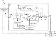
- FIG. 1is a schematic diagram of an exemplary ETIC 10 configured according to an embodiment of the present disclosure to maintain a higher operating efficiency in face of a wide range of bandwidth and/or load-line requirements.
- the ETIC 10includes an ET voltage circuit 12 configured to generate an ET voltage V CC based on a lower supply voltage V SUP-L or a higher supply voltage V SUP-H (collectively referred to as “at least one supply voltage”).
- the ETIC 10also includes a supply voltage circuit 14 configured to generate the lower supply voltage V SUP-L or the higher supply voltage V SUP-H .
- the supply voltage circuit 14may be configured to receive a lower supply target voltage V SUPPL-TGT or a higher supply target voltage V SUPH-TGT (collectively referred to as “at least one supply target voltage”).
- the supply voltage circuit 14can be configured to generate the lower supply voltage V SUP-L in response to receiving the lower supply target voltage V SUPL-TGT and generate the higher supply voltage V SUP-H in response to receiving the higher supply target voltage V SUPH-TGT .
- the lower supply voltage V SUP-Lmay be proportionally related to the lower supply target voltage V SUPL-TGT and the higher supply voltage V SUP-H may be proportionally related to the higher supply target voltage V SUPH-TGT .
- the ET voltage circuit 12includes a voltage amplifier 16 and an offset capacitor 18 .
- the voltage amplifier 16is configured to generate an initial ET voltage V AMP based on the lower supply voltage V SUP-L or the higher supply voltage V SUP-H .
- V OFFoffset voltage
- the ETIC 10may be coupled to an amplifier circuit 22 configured to amplify an RF signal 24 based on the ET voltage V CC .
- the amplifier circuit 22may exhibit different load-line impedances to the ETIC 10 and the RF signal 24 may correspond to different modulation bandwidths.
- the ETIC 10may be required to adapt the ET voltage V CC accordingly to help improve operating efficiency of the amplifier circuit 22 .
- the supply voltage circuit 14is configured to provide the higher supply voltage V SUP-H to the voltage amplifier 16 to help avoid amplitude clipping when the ET voltage is near the peak.
- the supply voltage circuit 14may be configured to provide the lower supply voltage V SUP-L to the voltage amplifier 16 to help improve operating efficiency of the voltage amplifier 16 when the ET voltage is close to an average.
- the voltage amplifier 16will be more efficient when operating based on the lower supply voltage V SUP-L than operating based on the higher supply voltage V SUP-H . Given that the voltage amplifier is less efficient when operating based on the higher supply voltage V SUP-H , it may be desirable to improve overall efficiency of the voltage amplifier 16 at the higher supply voltage V SUP-H .
- the ETIC 10is further configured to include a control circuit 26 , which can be a microprocessor, a microcontroller, or a field-programmable gate array (FPGA), as an example.
- the control circuit 26is configured to determine the peak of the ET voltage V CC , for example on a periodic basis. Accordingly, the control circuit 26 can be configured to dynamically adjust the higher supply target voltage V SUPH-TGT based on the determined peak of the ET voltage V CC to cause the supply voltage circuit 14 to adjust the higher supply voltage V SUP-H .
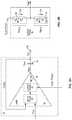
- FIG. 2Ais a schematic diagram providing an exemplary illustration of the voltage amplifier 16 in the ETIC 10 of FIG. 1 . Common elements between FIGS. 1 and 2A are shown therein with common element numbers and will not be re-described herein.
- the voltage amplifier 16includes at least one input stage 28 and at least one output stage 30 .
- the input stage 28may be configured to receive an ET target voltage V TGT and the output stage 30 is configured to receive the lower supply voltage V SUP-L or the higher supply voltage V SUP-H .
- Collectively, the input stage 28 and the output stage 30cause the voltage amplifier 16 to generate the initial ET voltage V AMP based on the ET target voltage V TGT and one of the lower supply voltage V SUP-L and the higher supply voltage V SUP-H .
- the input stage 28may be further configured to receive a feedback voltage V CCFB , which is proportional to the ET voltage V CC , such that the ET voltage circuit 12 can generate the ET voltage V CC based on a closed-loop envelope tracking mechanism.
- the voltage amplifier 16may also source or sink a high-frequency current l AC (e.g., an alternating current) depending on the modulation bandwidth of the RF signal 24 .
- FIG. 2Bis a schematic diagram providing an exemplary illustration of the output stage 30 in the voltage amplifier 16 of FIG. 2A . Common elements between FIGS. 2A and 2B are shown therein with common element numbers and will not be re-described herein.
- the output stage 30includes a p-type field-effect transistor (PFET) stack 32 and an n-type field-effect transistor (NFET) stack 34 .
- the PFET stack 32may include at least one PFET 36 and corresponds to an equivalent resistance R PFET .
- the NFET stack 34may include at least one NFET 38 and corresponds to an equivalent resistance R NFET .
- the PFET stack 32may be coupled to the supply voltage circuit 14 to receive the lower supply voltage V SUP-L or the higher supply voltage V SUP-H .
- the PFET stack 32may be configured to source the high-frequency current l AC , for example, when the RF signal 24 exhibits a higher peak-to-average ratio (PAR).
- the NFET stack 34may be coupled between the PFET stack 32 and a ground (GND).
- the NFET stack 34may be configured to sink the high-frequency current l AC , for example, when the RF signal 24 exhibits a lower PAR.
- the supply voltage circuit 14may be configured to generate the higher supply voltage V SUP-H based on the equation (Eq. 1) below.
- V SUP-HV CC-MAX ⁇ V OFF +P headroom (Eq. 1)
- V CC-MAXrepresents the peak of the ET voltage V CC and P headroom represents a defined headroom voltage corresponding to the PAR of the RF signal 24 .
- P headroomR PFET *I AC-MAX (Eq. 2)
- R PFETrepresents the equivalent resistance of the PFET stack 32 in the output stage 30 of the voltage amplifier 16 .
- I AC-MAXrepresents a peak of the high-frequency current l AC , which typically coincides with the peak of the ET voltage V CC , sourced by the voltage amplifier 16 .
- the control circuit 26may be configured to periodically determine a headroom voltage variation ⁇ P headroom relative to the defined headroom voltage P headroom . Accordingly, the control circuit 26 may adjust the higher supply target voltage V SUPH-TGT to cause the supply voltage circuit 14 to adjust the higher supply voltage V SUP-H .
- control circuit 26can determine the headroom voltage variation ⁇ P headroom based on the equation (Eq. 3) below.
- ⁇ P headroomR PFET *( I AC-MAX-REF ⁇ I AC-MAX ) (Eq. 3)
- I AC-MAX-REFrepresents the peak of the high-frequency current l AC corresponding to the defined headroom voltage P headroom and I AC-MAX represents a presently determined peak of the high-frequency current I AC corresponding to a presently determined peak of the ET voltage V CC .
- I AC-MAX-REFcorresponds to the peak of the high-frequency current l AC in a first duration and l AC-MAX corresponds to the peak of the high-frequency current l AC in a second duration succeeding the first duration, as illustrated in FIG. 3 .
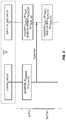
- FIG. 3is a graphic diagram providing an exemplary illustration of the ETIC 10 of FIG. 1 configured to maintain the higher operating efficiency on a periodic basis.
- the first duration and the second durationcan correspond to a timeslot N and a timeslot N+1, among a number of continuous timeslots.
- I AC-MAX-REFcorresponds to the peak of the high-frequency current l AC in the timeslot N
- I AC-MAXcorresponds to the peak of the high-frequency current I AC in the timeslot N+1, which immediately succeeds the timeslot N.
- the control circuit 26may determine the headroom voltage variation ⁇ P headroom .
- the control circuit 26may determine the higher supply target voltage V SUPH-TGT based on the headroom voltage variation ⁇ P headroom .
- the control circuit 26may subsequently provide the updated higher supply target voltage V SUPH-TGT to the supply voltage circuit 14 .
- the supply voltage circuit 14may generate the updated higher supply voltage V SUP-H in the succeeding timeslot N+1.
- the voltage amplifier 16may be configured to generate a sense current I SNS that is proportionally related to the high-frequency current I AC sourced by the voltage amplifier 16 .
- the control circuit 26may be configured to determine the peak of the high-frequency current I AC-MAX , and thus the headroom voltage variation ⁇ P headroom , based on the sense current I SNS .
- the ETIC 10may be configured to include a headroom adjuster 40 coupled between the control circuit 26 and the supply voltage circuit 14 .
- the headroom adjuster 40can be configured to determine the headroom voltage variation ⁇ P headroom based on the sense current I SNS . Accordingly, the headroom adjuster 40 may adjust the higher supply target voltage V SUPH-TGT based on the headroom voltage variation ⁇ P headroom to cause the supply voltage circuit 14 to adjust the higher supply voltage V SUP-H .
- the ETIC 10can be further configured to include a multi-level charge pump (MCP) 42 and a power inductor 44 .
- MCPmulti-level charge pump
- the MCP 42may be configured to generate a low-frequency voltage V DC (e.g., a constant voltage) based on a battery voltage V BAT .
- the power inductor 44may be configured to induce a low-frequency current I DC (e.g., a direct current) based on the low-frequency voltage V DC .
- the power inductor 44may be coupled to the output port 20 to provide the low-frequency current I DC to the output port 20 .
- the ETIC 10may be coupled to a transceiver circuit 46 , which is configured to generate and provide the RF signal 24 to the amplifier circuit 22 .
- the transceiver circuit 46may be configured to generate and provide the lower supply target voltage V SUPL-TGT and/or the higher supply target voltage V SUPH-TGT to the supply voltage circuit 14 .
- the control circuit 26can be configured to provide the headroom voltage variation ⁇ P headroom (e.g., via an indication signal 48 ) to the transceiver circuit 46 . Accordingly, the transceiver circuit 46 may adjust the higher supply target voltage V SUPH-TGT to cause the supply voltage circuit 14 to adjust the higher supply voltage V SUP-H .
- the ETIC 10may be configured to effectuate the updated higher supply voltage V SUP-H in the succeeding timeslot N+1, as opposed to the present timeslot N, to avoid unintended disruption to the voltage amplifier 16 .
- the transceiver circuit 46may be configured to provide a boundary indication signal 50 configured to indicate the boundary between the timeslot N and the timeslot N+1.
- the ETIC 10 , the amplifier circuit 22 , and the transceiver circuit 46may be integrated into an ET apparatus 52 .
Landscapes
- Engineering & Computer Science (AREA)
- Power Engineering (AREA)
- Microelectronics & Electronic Packaging (AREA)
- Amplifiers (AREA)
Abstract
Description
VSUP-H=VCC-MAX−VOFF+Pheadroom (Eq. 1)
Pheadroom=RPFET*IAC-MAX (Eq. 2)
ΔPheadroom=RPFET*(IAC-MAX-REF−IAC-MAX) (Eq. 3)
Claims (20)
Priority Applications (1)
| Application Number | Priority Date | Filing Date | Title |
|---|---|---|---|
| US16/661,061US11031911B2 (en) | 2019-05-02 | 2019-10-23 | Envelope tracking integrated circuit and related apparatus |
Applications Claiming Priority (2)
| Application Number | Priority Date | Filing Date | Title |
|---|---|---|---|
| US201962842486P | 2019-05-02 | 2019-05-02 | |
| US16/661,061US11031911B2 (en) | 2019-05-02 | 2019-10-23 | Envelope tracking integrated circuit and related apparatus |
Publications (2)
| Publication Number | Publication Date |
|---|---|
| US20200350865A1 US20200350865A1 (en) | 2020-11-05 |
| US11031911B2true US11031911B2 (en) | 2021-06-08 |
Family
ID=73016726
Family Applications (1)
| Application Number | Title | Priority Date | Filing Date |
|---|---|---|---|
| US16/661,061Active2039-11-25US11031911B2 (en) | 2019-05-02 | 2019-10-23 | Envelope tracking integrated circuit and related apparatus |
Country Status (1)
| Country | Link |
|---|---|
| US (1) | US11031911B2 (en) |
Families Citing this family (17)
| Publication number | Priority date | Publication date | Assignee | Title |
|---|---|---|---|---|
| US11309922B2 (en) | 2019-12-13 | 2022-04-19 | Qorvo Us, Inc. | Multi-mode power management integrated circuit in a small formfactor wireless apparatus |
| US11349513B2 (en) | 2019-12-20 | 2022-05-31 | Qorvo Us, Inc. | Envelope tracking system |
| US11539330B2 (en) | 2020-01-17 | 2022-12-27 | Qorvo Us, Inc. | Envelope tracking integrated circuit supporting multiple types of power amplifiers |
| US11716057B2 (en) | 2020-01-28 | 2023-08-01 | Qorvo Us, Inc. | Envelope tracking circuitry |
| US11728774B2 (en) | 2020-02-26 | 2023-08-15 | Qorvo Us, Inc. | Average power tracking power management integrated circuit |
| US11588449B2 (en) | 2020-09-25 | 2023-02-21 | Qorvo Us, Inc. | Envelope tracking power amplifier apparatus |
| US11728796B2 (en) | 2020-10-14 | 2023-08-15 | Qorvo Us, Inc. | Inverted group delay circuit |
| US11909385B2 (en) | 2020-10-19 | 2024-02-20 | Qorvo Us, Inc. | Fast-switching power management circuit and related apparatus |
| CN112543000B (en)* | 2020-11-09 | 2022-02-15 | 武汉市聚芯微电子有限责任公司 | Power supply circuit, method, audio power amplifier and integrated circuit |
| US12265442B2 (en) | 2020-12-04 | 2025-04-01 | Qorvo Us, Inc. | Power management integrated circuit |
| EP4268364B1 (en) | 2020-12-22 | 2024-11-27 | Qorvo US, Inc. | Power management apparatus operable with multiple configurations |
| US12267046B2 (en) | 2021-02-15 | 2025-04-01 | Qorvo Us, Inc. | Power amplifier system |
| US12068720B2 (en) | 2021-02-26 | 2024-08-20 | Qorvo Us, Inc. | Barely Doherty dual envelope tracking (BD2E) circuit |
| US12212286B2 (en) | 2021-03-05 | 2025-01-28 | Qorvo Us, Inc. | Complementary envelope detector |
| US12126305B2 (en) | 2021-05-27 | 2024-10-22 | Qorvo Us, Inc. | Radio frequency (RF) equalizer in an envelope tracking (ET) circuit |
| US12063018B2 (en) | 2021-06-10 | 2024-08-13 | Qorvo Us, Inc. | Envelope tracking integrated circuit operable with multiple types of power amplifiers |
| US12335073B2 (en)* | 2021-11-04 | 2025-06-17 | Qorvo Us, Inc. | Intra-symbol voltage modulation in a wireless communication circuit |
Citations (148)
| Publication number | Priority date | Publication date | Assignee | Title |
|---|---|---|---|---|
| US5838732A (en) | 1994-10-31 | 1998-11-17 | Airnet Communications Corp. | Reducing peak-to-average variance of a composite transmitted signal generated by a digital combiner via carrier phase offset |
| US6107862A (en) | 1997-02-28 | 2000-08-22 | Seiko Instruments Inc. | Charge pump circuit |
| US6141377A (en) | 1998-07-30 | 2000-10-31 | Cisco Technology, Inc. | Method and apparatus for voice frequency noise reduction in splitterless ADSL |
| US20020167827A1 (en) | 2001-01-29 | 2002-11-14 | Hiroyuki Umeda | Power supply apparatus |
| US20040266366A1 (en) | 2003-06-24 | 2004-12-30 | Ian Robinson | Multi-mode amplifier system |
| US20050090209A1 (en) | 2003-10-23 | 2005-04-28 | Behzad Arya R. | High linearity, high efficiency power amplifier with DSP assisted linearity optimization |
| US20050227646A1 (en) | 2004-03-18 | 2005-10-13 | Ryo Yamazaki | Detecting and maintaining linearity in a power amplifier system through comparing peak and RMS power levels |
| US20050232385A1 (en) | 2004-03-02 | 2005-10-20 | Matsushita Electric Industrial Co., Ltd. | Two-point frequency modulation apparatus, wireless transmitting apparatus, and wireless receiving apparatus |
| US6985033B1 (en) | 2003-05-15 | 2006-01-10 | Marvell International Ltd. | Circuits and methods for adjusting power amplifier predistortion, and power amplifiers and other devices including the same |
| US20060240786A1 (en) | 2002-10-31 | 2006-10-26 | Xiaowei Liu | Method and system for broadband predistortion linearization |
| US20070052474A1 (en) | 2005-09-05 | 2007-03-08 | Fujitsu Limited | Amplifier and device having amplifier, and mutual conductance control method |
| US20070258602A1 (en) | 2006-05-05 | 2007-11-08 | Nokia Corporation | Method and arrangement for optimizing efficiency of a power amplifier |
| US7471155B1 (en) | 2007-05-25 | 2008-12-30 | Rf Micro Devices, Inc. | Cancelling switching power supply ripple from a radio frequency signal |
| US20090016085A1 (en) | 2007-07-11 | 2009-01-15 | Semtech Corporation | Method and Apparatus for a Charge Pump DC-to-DC Converter Having Parallel Operating Modes |
| US20090045872A1 (en) | 2005-03-07 | 2009-02-19 | Peter Blakeborough Kenington | Integrated transceiver with envelope tracking |
| US20090191826A1 (en) | 2008-01-29 | 2009-07-30 | Matsushita Electric Industrial Co., Ltd. | High-Efficiency Envelope Tracking Systems and Methods for Radio Frequency Power Amplifiers |
| US7570931B2 (en) | 2006-06-02 | 2009-08-04 | Crestcom, Inc. | RF transmitter with variably biased RF power amplifier and method therefor |
| US20100308919A1 (en) | 2009-06-03 | 2010-12-09 | Jaroslaw Adamski | Methods and devices for leakage current reduction |
| US20110074373A1 (en) | 2009-09-29 | 2011-03-31 | Richtek Technology Corp. | Control circuit and method for a buck-boost power converter |
| US20110136452A1 (en) | 2008-08-20 | 2011-06-09 | Freescale Semiconductor, Inc. | Wireless communication unit, integrated circuit and method of power control of a power amplifier therefor |
| US20110175681A1 (en) | 2010-01-21 | 2011-07-21 | Panasonic Corporation | Radio frequency power amplifier and wireless communication device including the same |
| US20110279179A1 (en) | 2010-05-17 | 2011-11-17 | Avago Technologies Wireless Ip (Singapore) | Apparatus and method for controlling power amplifier |
| US20120194274A1 (en) | 2011-02-01 | 2012-08-02 | Paul Fowers | Integrated circuit, wireless communication unit and method for providing a power supply |
| US20120200435A1 (en) | 2011-02-07 | 2012-08-09 | Rf Micro Devices, Inc. | Apparatuses and methods for rate conversion and fractional delay calculation using a coefficient look up table |
| US20120299645A1 (en) | 2010-04-20 | 2012-11-29 | Rf Micro Devices, Inc. | Temperature correcting an envelope power supply signal for rf pa circuitry |
| US20120299647A1 (en) | 2010-04-20 | 2012-11-29 | Rf Micro Devices, Inc. | Pa envelope power supply undershoot compensation |
| US20130021827A1 (en) | 2011-07-22 | 2013-01-24 | Zhong Ye | System and method for envelope tracking power supply |
| US20130100991A1 (en) | 2011-10-20 | 2013-04-25 | Samsung Electronics Co. Ltd. | Digital pre-distortion method and apparatus thereof for changing memory degree depending on input level |
| US20130130724A1 (en) | 2011-11-21 | 2013-05-23 | Broadcom Corporation | Wireless communication device capable of efficient network search |
| US8461928B2 (en) | 2011-01-25 | 2013-06-11 | Provigent Ltd. | Constant-gain power amplifier |
| US20130162233A1 (en) | 2011-12-27 | 2013-06-27 | St-Ericsson Sa | Single feedback loop for parallel architecture buck converter - ldo regulator |
| US8493141B2 (en) | 2010-04-19 | 2013-07-23 | Rf Micro Devices, Inc. | Pseudo-envelope following power management system |
| US20130187711A1 (en) | 2012-01-19 | 2013-07-25 | Motorola Mobility, Inc. | Method and apparatus for resource block based transmitter optimization in wireless communication devices |
| US20130200865A1 (en) | 2010-08-13 | 2013-08-08 | Nujira Limited | Switch mode power supply for envelope tracking |
| US8519788B2 (en)* | 2010-04-19 | 2013-08-27 | Rf Micro Devices, Inc. | Boost charge-pump with fractional ratio and offset loop for supply modulation |
| US20130271221A1 (en) | 2010-04-20 | 2013-10-17 | Rf Micro Devices, Inc. | Direct current (dc)-dc converter having a multi-stage output filter |
| US8588713B2 (en) | 2011-01-10 | 2013-11-19 | Rf Micro Devices, Inc. | Power management system for multi-carriers transmitter |
| US20140009226A1 (en) | 2012-07-08 | 2014-01-09 | R2 Semiconductor, Inc. | Decoupling circuits for filtering a voltage supply of multiple power amplifiers |
| US20140028390A1 (en) | 2012-07-25 | 2014-01-30 | Qualcomm Incorporated | Energy source sharing |
| US20140028370A1 (en) | 2012-01-16 | 2014-01-30 | Nujira Limited | Crest Factor Reduction Applied To Shaping Table To Increase Power Amplifier Efficiency Of Envelope Tracking Amplifier |
| US20140057684A1 (en) | 2011-05-05 | 2014-02-27 | Rf Micro Devices, Inc. | Power loop control based envelope tracking |
| US20140103995A1 (en) | 2012-10-15 | 2014-04-17 | Andreas Langer | Control Circuit and Method for Controlling an Operation of a Power Amplifier |
| US8718188B2 (en) | 2011-04-25 | 2014-05-06 | Skyworks Solutions, Inc. | Apparatus and methods for envelope tracking |
| US8725218B2 (en) | 2011-03-25 | 2014-05-13 | R2 Semiconductor, Inc. | Multimode operation DC-DC converter |
| US20140155002A1 (en) | 2012-12-03 | 2014-06-05 | Broadcom Corporation | Envelope Tracking Signal Bandwidth Control |
| US20140184335A1 (en) | 2012-12-28 | 2014-07-03 | Peregrine Semiconductor Corporation | Amplifiers Operating in Envelope Tracking Mode or Non-Envelope Tracking Mode |
| US8774065B2 (en) | 2011-05-02 | 2014-07-08 | Rf Micro Devices, Inc. | Radio front end and power management architecture for LTE-advanced |
| US20140199949A1 (en) | 2013-01-16 | 2014-07-17 | Motorola Mobility Llc | Method for improving tx gain in envelope tracking systems |
| US20140210550A1 (en) | 2013-01-28 | 2014-07-31 | Qualcomm Incorporated | Reverse current prevention |
| US20140218109A1 (en) | 2013-02-01 | 2014-08-07 | Nujira Limited | 2g support for 2g and 3g/4g envelope tracking modulator |
| US8803603B2 (en) | 2011-06-24 | 2014-08-12 | Nujira Limited | Envelope tracking system for MIMO |
| US20140235185A1 (en) | 2012-03-04 | 2014-08-21 | Quantance, Inc. | Envelope Tracking Power Amplifier System with Delay Calibration |
| US8818305B1 (en) | 2012-11-14 | 2014-08-26 | Motorola Mobility Llc | Supply transitions in an envelope tracked power amplifier |
| US20140266423A1 (en) | 2013-03-15 | 2014-09-18 | Quantance, Inc. | Envelope Tracking System with Internal Power Amplifier Characterization |
| US20140266428A1 (en) | 2013-03-14 | 2014-09-18 | Rf Micro Devices, Inc. | Envelope tracking power supply voltage dynamic range reduction |
| US8854129B2 (en) | 2010-04-15 | 2014-10-07 | Nujira Limited | Timing alignment for modulated supply |
| US20140315504A1 (en) | 2013-04-17 | 2014-10-23 | Fujitsu Limited | Power supply circuit, power supply system, and radio communication apparatus |
| US8879665B2 (en) | 2011-06-08 | 2014-11-04 | Broadcom Corporation | Controlling a power amplifier based on transmitter output emissions |
| US20140361830A1 (en) | 2013-06-06 | 2014-12-11 | Qualcomm Incorporated | Envelope tracker with variable boosted supply voltage |
| US8913690B2 (en) | 2011-05-13 | 2014-12-16 | Sumitomo Electric Industries, Ltd. | Amplifier circuit and wireless communication equipment |
| US20150048883A1 (en) | 2013-08-14 | 2015-02-19 | Quantance, Inc. | Stabilizing a Power Combining Power Supply System |
| US20150071382A1 (en) | 2013-09-12 | 2015-03-12 | Fujitsu Limited | Digital pre-distortion transmitter and method for controlling the same |
| US8989682B2 (en) | 2011-02-07 | 2015-03-24 | Skyworks Solutions, Inc. | Apparatus and methods for envelope tracking calibration |
| US20150098523A1 (en) | 2013-10-04 | 2015-04-09 | Samsung Electronics Co., Ltd. | Apparatus and method for power amplification |
| US9020451B2 (en) | 2012-07-26 | 2015-04-28 | Rf Micro Devices, Inc. | Programmable RF notch filter for envelope tracking |
| US9041365B2 (en) | 2011-12-01 | 2015-05-26 | Rf Micro Devices, Inc. | Multiple mode RF power converter |
| US9041364B2 (en) | 2011-12-01 | 2015-05-26 | Rf Micro Devices, Inc. | RF power converter |
| US20150155836A1 (en) | 2013-12-02 | 2015-06-04 | Futurewei Technologies, Inc. | Nonlinear Load Pre-Distortion for Open Loop Envelope Tracking |
| US9055529B2 (en) | 2013-10-04 | 2015-06-09 | Samsung Electronics Co., Ltd. | System and method for adaptive in-network time alignment for envelope tracking power amplifier |
| US9065509B1 (en) | 2014-01-09 | 2015-06-23 | Mediatek Inc. | Methods and apparatus for envelope tracking system |
| US9069365B2 (en) | 2012-02-18 | 2015-06-30 | R2 Semiconductor, Inc. | DC-DC converter enabling rapid output voltage changes |
| US20150188432A1 (en) | 2012-08-10 | 2015-07-02 | Texas Instruments Incorporated | Switched mode assisted linear regulator with seamless transition between power tracking configurations |
| US9098099B2 (en) | 2010-11-11 | 2015-08-04 | Samsung Electronics Co., Ltd. | Device and method for increasing output efficiency of mobile communication terminal |
| US20150236654A1 (en) | 2014-02-19 | 2015-08-20 | Futurewei Technologies, Inc. | Envelope Tracking Apparatus and Method |
| US20150236729A1 (en) | 2014-02-16 | 2015-08-20 | Mediatek Inc. | Methods and apparatus for envelope tracking system |
| US20150280652A1 (en) | 2014-03-28 | 2015-10-01 | Intel IP Corporation | Apparatus and a Method for Providing a Supply Control Signal for a Supply Unit |
| US9167514B2 (en) | 2012-12-03 | 2015-10-20 | Broadcom Corporation | Unequal amplifier gain compression via shaping table |
| US9166538B2 (en) | 2011-02-01 | 2015-10-20 | Mediatek Singapore Pte. Ltd. | Integrated circuit wireless communication unit and method for providing a power supply |
| US9166830B2 (en) | 2013-07-18 | 2015-10-20 | Intel Deutschland Gmbh | Systems and methods utilizing adaptive envelope tracking |
| US20150333781A1 (en) | 2014-05-19 | 2015-11-19 | Skyworks Solutions, Inc. | Rf transceiver front end module with improved linearity |
| US9197182B2 (en) | 2010-02-01 | 2015-11-24 | Rf Micro Devices, Inc. | Envelope power supply calibration of a multi-mode radio frequency power amplifier |
| US9225362B2 (en) | 2013-03-14 | 2015-12-29 | Quantance, Inc. | Power supply |
| US9263997B2 (en) | 2013-03-14 | 2016-02-16 | Quantance, Inc. | Self setting power supply using negative output impedance |
| US9270230B2 (en) | 2008-11-18 | 2016-02-23 | Snaptrack, Inc. | Power supply arrangement for multi-stage amplifier |
| US9271236B2 (en) | 2013-03-14 | 2016-02-23 | Quantance, Inc. | ET system with adjustment for noise |
| US20160065137A1 (en) | 2014-08-26 | 2016-03-03 | Rf Micro Devices, Inc. | Reduced bandwidth envelope tracking |
| US9280163B2 (en) | 2011-12-01 | 2016-03-08 | Rf Micro Devices, Inc. | Average power tracking controller |
| US9298198B2 (en) | 2011-12-28 | 2016-03-29 | Rf Micro Devices, Inc. | Noise reduction for envelope tracking |
| US20160099687A1 (en) | 2014-10-03 | 2016-04-07 | Rf Micro Devices, Inc. | Envelope tracking with reduced dynamic range |
| US20160105151A1 (en) | 2014-10-13 | 2016-04-14 | Intel Corporation | Switchable Dual Core Power Amplifier |
| US20160118941A1 (en) | 2013-05-29 | 2016-04-28 | Nokia Technologies Oy | Amplication of a radio frequency signal |
| US20160126900A1 (en) | 2013-05-22 | 2016-05-05 | Snaptrack, Inc. | Transfer function regulation |
| US9344304B1 (en) | 2014-12-18 | 2016-05-17 | Intel IP Corporation | Communication device with power supply load variation noise reduction for envelope tracking and method therefor |
| US9356512B2 (en) | 2013-07-29 | 2016-05-31 | Broadcom Corporation | Envelope tracking power supply with direct connection to power source |
| US20160173031A1 (en) | 2014-12-12 | 2016-06-16 | Intel Corporation | Envelope Tracking in Connection with Simultaneous Transmission in one or more Frequency Bands |
| US20160181995A1 (en) | 2014-12-23 | 2016-06-23 | Nokia Corporation | Reconfigurable bias and supply drivers for radio frequency power amplifiers |
| US9379667B2 (en) | 2011-05-05 | 2016-06-28 | Rf Micro Devices, Inc. | Multiple power supply input parallel amplifier based envelope tracking |
| US20160187627A1 (en) | 2014-12-24 | 2016-06-30 | Canon Kabushiki Kaisha | Zoom lens and image pickup apparatus including the same |
| US20160197627A1 (en) | 2015-01-04 | 2016-07-07 | Huawei Technologies Co., Ltd. | Digital predistortion system and method based on envelope tracking and radio frequency system |
| US20160294587A1 (en) | 2015-04-02 | 2016-10-06 | Futurewei Technologies, Inc. | Open loop digital pwm envelope tracking system with dynamic boosting |
| US9595869B2 (en) | 2015-02-27 | 2017-03-14 | Qualcomm Incorporated | Multi-level switching regulator circuits and methods with finite state machine control |
| US9614477B1 (en) | 2016-01-12 | 2017-04-04 | Avago Technologies General Ip (Singapore) Pte. Ltd. | Envelope tracking supply modulators for multiple power amplifiers |
| US9634666B2 (en)* | 2014-12-23 | 2017-04-25 | Intel IP Corporation | Push-pull driver, a transmitter, a receiver, a transceiver, an integrated circuit, a method for generating a signal at an output |
| US20170141736A1 (en) | 2015-11-13 | 2017-05-18 | Analog Devices Global | Broadband envelope tracking |
| EP3174199A2 (en) | 2011-05-05 | 2017-05-31 | Qorvo US, Inc. | Power management architecture for modulated and constant supply operation |
| US9748845B1 (en) | 2013-11-02 | 2017-08-29 | Sridhar Kotikalapoodi | Method and apparatus for wide bandwidth, efficient power supply |
| US20170302183A1 (en) | 2014-10-06 | 2017-10-19 | Zentrum Mikroelektronik Dresden Ag | Pulsed linear power converter |
| US9806676B2 (en) | 2015-07-28 | 2017-10-31 | Skyworks Solutions, Inc. | Power amplification system with programmable load line |
| US20170317913A1 (en) | 2016-04-28 | 2017-11-02 | Samsung Electronics Co., Ltd. | System and method for frequency-domain weighted least squares |
| US20170338773A1 (en) | 2016-05-17 | 2017-11-23 | Skyworks Solutions, Inc. | Power amplification system with envelope-based bias |
| US9831834B2 (en) | 2014-07-29 | 2017-11-28 | Skyworks Solutions, Inc. | Envelope tracking with low frequency loss correction |
| US20180013465A1 (en) | 2016-07-06 | 2018-01-11 | Qorvo Us, Inc. | Multi-mode radio frequency circuitry |
| US20180048276A1 (en) | 2016-08-12 | 2018-02-15 | Qorvo Us, Inc. | Multi-mode envelope tracking amplifier circuit |
| US20180048265A1 (en) | 2015-02-23 | 2018-02-15 | Nokia Technologies Oy | Method and Apparatus for Supplying Power to an Amplifier |
| US20180076772A1 (en) | 2016-09-14 | 2018-03-15 | Skyworks Solutions, Inc. | Apparatus and methods for envelope tracking systems with automatic mode selection |
| US9923520B1 (en) | 2016-09-21 | 2018-03-20 | Qualcomm Incorporated | Switching power supply for RF power amplifiers |
| US20180123453A1 (en) | 2016-11-01 | 2018-05-03 | Lion Semiconductor Inc. | Feedback control for efficient high-speed battery charging |
| US10003416B1 (en) | 2016-12-16 | 2018-06-19 | Rohde & Schwarz Gmbh & Co. Kg | Method for measuring characteristics of a transmitter unit of a device under test, test system and radio frequency device |
| US10090808B1 (en) | 2017-03-30 | 2018-10-02 | Intel IP Corporation | Feed-forward envelope tracking |
| US20180288697A1 (en) | 2017-03-31 | 2018-10-04 | Intel IP Corporation | Adaptive envelope tracking threshold |
| US10097145B1 (en) | 2017-12-11 | 2018-10-09 | Qorvo Us, Inc. | Multi-mode power management circuit |
| US20180302042A1 (en) | 2015-12-24 | 2018-10-18 | Huawei Technologies Co., Ltd. | Power amplifier control method and apparatus, and power amplifier control system |
| US20180309414A1 (en) | 2017-04-25 | 2018-10-25 | Qorvo Us, Inc. | Envelope tracking amplifier circuit |
| US10158329B1 (en) | 2017-07-17 | 2018-12-18 | Qorvo Us, Inc. | Envelope tracking power amplifier circuit |
| US10158330B1 (en)* | 2017-07-17 | 2018-12-18 | Qorvo Us, Inc. | Multi-mode envelope tracking amplifier circuit |
| US20180367101A1 (en) | 2017-06-19 | 2018-12-20 | Realtek Semiconductor Corporation | Envelope-tracking power supply modulator |
| US10170989B2 (en) | 2010-09-03 | 2019-01-01 | Skyworks Solutions, Inc. | Methods for fabricating an integrated circuit with a voltage regulator |
| US20190068234A1 (en) | 2017-08-31 | 2019-02-28 | Qorvo Us, Inc. | Multi radio access technology power management circuit |
| US20190097277A1 (en) | 2016-04-27 | 2019-03-28 | Autonetworks Technologies, Ltd. | Power source device |
| US20190109613A1 (en) | 2017-10-06 | 2019-04-11 | Qorvo Us, Inc. | Envelope tracking system for transmitting a wide modulation bandwidth signal(s) |
| US10291181B2 (en) | 2016-11-02 | 2019-05-14 | Samsung Electronics Co., Ltd. | Supply modulator and communication device including the same |
| US10326408B2 (en) | 2017-09-18 | 2019-06-18 | Qorvo Us, Inc. | Envelope tracking power management circuit |
| US20190222175A1 (en) | 2018-01-15 | 2019-07-18 | Qorvo Us, Inc. | Envelope tracking power management circuit |
| US20190222178A1 (en) | 2018-01-18 | 2019-07-18 | Qorvo Us, Inc. | Envelope tracking voltage tracker circuit and related power management circuit |
| US10382071B2 (en) | 2016-01-27 | 2019-08-13 | Qorvo Us, Inc. | Bandwidth optimization for power amplifier power supplies |
| US20190267956A1 (en) | 2018-02-28 | 2019-08-29 | Qorvo Us, Inc. | Power amplifier apparatus supporting reverse intermodulation product cancellation |
| US10476437B2 (en) | 2018-03-15 | 2019-11-12 | Qorvo Us, Inc. | Multimode voltage tracker circuit |
| US20200007090A1 (en) | 2018-06-28 | 2020-01-02 | Qorvo Us, Inc. | Envelope tracking amplifier circuit |
| US20200036337A1 (en) | 2018-07-24 | 2020-01-30 | Qorvo Us, Inc. | Envelope tracking amplifier apparatus |
| US20200136561A1 (en) | 2018-10-31 | 2020-04-30 | Qorvo Us, Inc. | Envelope tracking system |
| US20200136575A1 (en) | 2018-10-31 | 2020-04-30 | Qorvo Us, Inc. | Multimode envelope tracking circuit and related apparatus |
| US20200153394A1 (en) | 2018-11-12 | 2020-05-14 | Qorvo Us, Inc. | Radio frequency amplifier circuitry |
| US20200177131A1 (en) | 2018-12-04 | 2020-06-04 | Qorvo Us, Inc. | Group delay optimization circuit and related apparatus |
| US20200204116A1 (en) | 2018-12-19 | 2020-06-25 | Qorvo Us, Inc. | Envelope tracking integrated circuit and related apparatus |
| US20200228063A1 (en) | 2019-01-15 | 2020-07-16 | Qorvo Us, Inc. | Multi-radio access technology envelope tracking amplifier apparatus |
| US20200259685A1 (en) | 2019-02-07 | 2020-08-13 | Qorvo Us, Inc. | Adaptive frequency equalizer for wide modulation bandwidth envelope tracking |
| US20200259456A1 (en) | 2019-02-07 | 2020-08-13 | Qorvo Us, Inc. | Dual-input envelope tracking integrated circuit and related apparatus |
| US20200266766A1 (en) | 2019-02-18 | 2020-08-20 | Qorvo Us, Inc. | Modulated power apparatus |
- 2019
- 2019-10-23USUS16/661,061patent/US11031911B2/enactiveActive
Patent Citations (163)
| Publication number | Priority date | Publication date | Assignee | Title |
|---|---|---|---|---|
| US5838732A (en) | 1994-10-31 | 1998-11-17 | Airnet Communications Corp. | Reducing peak-to-average variance of a composite transmitted signal generated by a digital combiner via carrier phase offset |
| US6107862A (en) | 1997-02-28 | 2000-08-22 | Seiko Instruments Inc. | Charge pump circuit |
| US6141377A (en) | 1998-07-30 | 2000-10-31 | Cisco Technology, Inc. | Method and apparatus for voice frequency noise reduction in splitterless ADSL |
| US20020167827A1 (en) | 2001-01-29 | 2002-11-14 | Hiroyuki Umeda | Power supply apparatus |
| US20060240786A1 (en) | 2002-10-31 | 2006-10-26 | Xiaowei Liu | Method and system for broadband predistortion linearization |
| US6985033B1 (en) | 2003-05-15 | 2006-01-10 | Marvell International Ltd. | Circuits and methods for adjusting power amplifier predistortion, and power amplifiers and other devices including the same |
| US20040266366A1 (en) | 2003-06-24 | 2004-12-30 | Ian Robinson | Multi-mode amplifier system |
| US7043213B2 (en) | 2003-06-24 | 2006-05-09 | Northrop Grumman Corporation | Multi-mode amplifier system |
| US20050090209A1 (en) | 2003-10-23 | 2005-04-28 | Behzad Arya R. | High linearity, high efficiency power amplifier with DSP assisted linearity optimization |
| US20050232385A1 (en) | 2004-03-02 | 2005-10-20 | Matsushita Electric Industrial Co., Ltd. | Two-point frequency modulation apparatus, wireless transmitting apparatus, and wireless receiving apparatus |
| US20050227646A1 (en) | 2004-03-18 | 2005-10-13 | Ryo Yamazaki | Detecting and maintaining linearity in a power amplifier system through comparing peak and RMS power levels |
| US20090045872A1 (en) | 2005-03-07 | 2009-02-19 | Peter Blakeborough Kenington | Integrated transceiver with envelope tracking |
| US20070052474A1 (en) | 2005-09-05 | 2007-03-08 | Fujitsu Limited | Amplifier and device having amplifier, and mutual conductance control method |
| US20070258602A1 (en) | 2006-05-05 | 2007-11-08 | Nokia Corporation | Method and arrangement for optimizing efficiency of a power amplifier |
| US7570931B2 (en) | 2006-06-02 | 2009-08-04 | Crestcom, Inc. | RF transmitter with variably biased RF power amplifier and method therefor |
| US7471155B1 (en) | 2007-05-25 | 2008-12-30 | Rf Micro Devices, Inc. | Cancelling switching power supply ripple from a radio frequency signal |
| US20090016085A1 (en) | 2007-07-11 | 2009-01-15 | Semtech Corporation | Method and Apparatus for a Charge Pump DC-to-DC Converter Having Parallel Operating Modes |
| US20090191826A1 (en) | 2008-01-29 | 2009-07-30 | Matsushita Electric Industrial Co., Ltd. | High-Efficiency Envelope Tracking Systems and Methods for Radio Frequency Power Amplifiers |
| US20110136452A1 (en) | 2008-08-20 | 2011-06-09 | Freescale Semiconductor, Inc. | Wireless communication unit, integrated circuit and method of power control of a power amplifier therefor |
| US9270230B2 (en) | 2008-11-18 | 2016-02-23 | Snaptrack, Inc. | Power supply arrangement for multi-stage amplifier |
| US20100308919A1 (en) | 2009-06-03 | 2010-12-09 | Jaroslaw Adamski | Methods and devices for leakage current reduction |
| US20110074373A1 (en) | 2009-09-29 | 2011-03-31 | Richtek Technology Corp. | Control circuit and method for a buck-boost power converter |
| US20110175681A1 (en) | 2010-01-21 | 2011-07-21 | Panasonic Corporation | Radio frequency power amplifier and wireless communication device including the same |
| US9197182B2 (en) | 2010-02-01 | 2015-11-24 | Rf Micro Devices, Inc. | Envelope power supply calibration of a multi-mode radio frequency power amplifier |
| US8854129B2 (en) | 2010-04-15 | 2014-10-07 | Nujira Limited | Timing alignment for modulated supply |
| US8493141B2 (en) | 2010-04-19 | 2013-07-23 | Rf Micro Devices, Inc. | Pseudo-envelope following power management system |
| US8519788B2 (en)* | 2010-04-19 | 2013-08-27 | Rf Micro Devices, Inc. | Boost charge-pump with fractional ratio and offset loop for supply modulation |
| US20120299645A1 (en) | 2010-04-20 | 2012-11-29 | Rf Micro Devices, Inc. | Temperature correcting an envelope power supply signal for rf pa circuitry |
| US20120299647A1 (en) | 2010-04-20 | 2012-11-29 | Rf Micro Devices, Inc. | Pa envelope power supply undershoot compensation |
| US20130271221A1 (en) | 2010-04-20 | 2013-10-17 | Rf Micro Devices, Inc. | Direct current (dc)-dc converter having a multi-stage output filter |
| US20110279179A1 (en) | 2010-05-17 | 2011-11-17 | Avago Technologies Wireless Ip (Singapore) | Apparatus and method for controlling power amplifier |
| US20130200865A1 (en) | 2010-08-13 | 2013-08-08 | Nujira Limited | Switch mode power supply for envelope tracking |
| US10170989B2 (en) | 2010-09-03 | 2019-01-01 | Skyworks Solutions, Inc. | Methods for fabricating an integrated circuit with a voltage regulator |
| US9098099B2 (en) | 2010-11-11 | 2015-08-04 | Samsung Electronics Co., Ltd. | Device and method for increasing output efficiency of mobile communication terminal |
| US8588713B2 (en) | 2011-01-10 | 2013-11-19 | Rf Micro Devices, Inc. | Power management system for multi-carriers transmitter |
| US8461928B2 (en) | 2011-01-25 | 2013-06-11 | Provigent Ltd. | Constant-gain power amplifier |
| US9166538B2 (en) | 2011-02-01 | 2015-10-20 | Mediatek Singapore Pte. Ltd. | Integrated circuit wireless communication unit and method for providing a power supply |
| US20120194274A1 (en) | 2011-02-01 | 2012-08-02 | Paul Fowers | Integrated circuit, wireless communication unit and method for providing a power supply |
| US20120200435A1 (en) | 2011-02-07 | 2012-08-09 | Rf Micro Devices, Inc. | Apparatuses and methods for rate conversion and fractional delay calculation using a coefficient look up table |
| US8989682B2 (en) | 2011-02-07 | 2015-03-24 | Skyworks Solutions, Inc. | Apparatus and methods for envelope tracking calibration |
| US8725218B2 (en) | 2011-03-25 | 2014-05-13 | R2 Semiconductor, Inc. | Multimode operation DC-DC converter |
| US8718188B2 (en) | 2011-04-25 | 2014-05-06 | Skyworks Solutions, Inc. | Apparatus and methods for envelope tracking |
| US8774065B2 (en) | 2011-05-02 | 2014-07-08 | Rf Micro Devices, Inc. | Radio front end and power management architecture for LTE-advanced |
| US20140057684A1 (en) | 2011-05-05 | 2014-02-27 | Rf Micro Devices, Inc. | Power loop control based envelope tracking |
| US9379667B2 (en) | 2011-05-05 | 2016-06-28 | Rf Micro Devices, Inc. | Multiple power supply input parallel amplifier based envelope tracking |
| EP3174199A2 (en) | 2011-05-05 | 2017-05-31 | Qorvo US, Inc. | Power management architecture for modulated and constant supply operation |
| US9247496B2 (en) | 2011-05-05 | 2016-01-26 | Rf Micro Devices, Inc. | Power loop control based envelope tracking |
| US8913690B2 (en) | 2011-05-13 | 2014-12-16 | Sumitomo Electric Industries, Ltd. | Amplifier circuit and wireless communication equipment |
| US8879665B2 (en) | 2011-06-08 | 2014-11-04 | Broadcom Corporation | Controlling a power amplifier based on transmitter output emissions |
| US8803603B2 (en) | 2011-06-24 | 2014-08-12 | Nujira Limited | Envelope tracking system for MIMO |
| US20130021827A1 (en) | 2011-07-22 | 2013-01-24 | Zhong Ye | System and method for envelope tracking power supply |
| US20130100991A1 (en) | 2011-10-20 | 2013-04-25 | Samsung Electronics Co. Ltd. | Digital pre-distortion method and apparatus thereof for changing memory degree depending on input level |
| US20130130724A1 (en) | 2011-11-21 | 2013-05-23 | Broadcom Corporation | Wireless communication device capable of efficient network search |
| US9377797B2 (en) | 2011-12-01 | 2016-06-28 | Rf Micro Devices, Inc. | Multiple mode RF power converter |
| US9041364B2 (en) | 2011-12-01 | 2015-05-26 | Rf Micro Devices, Inc. | RF power converter |
| US9041365B2 (en) | 2011-12-01 | 2015-05-26 | Rf Micro Devices, Inc. | Multiple mode RF power converter |
| US9280163B2 (en) | 2011-12-01 | 2016-03-08 | Rf Micro Devices, Inc. | Average power tracking controller |
| US20130162233A1 (en) | 2011-12-27 | 2013-06-27 | St-Ericsson Sa | Single feedback loop for parallel architecture buck converter - ldo regulator |
| US9298198B2 (en) | 2011-12-28 | 2016-03-29 | Rf Micro Devices, Inc. | Noise reduction for envelope tracking |
| US20140028370A1 (en) | 2012-01-16 | 2014-01-30 | Nujira Limited | Crest Factor Reduction Applied To Shaping Table To Increase Power Amplifier Efficiency Of Envelope Tracking Amplifier |
| US20130187711A1 (en) | 2012-01-19 | 2013-07-25 | Motorola Mobility, Inc. | Method and apparatus for resource block based transmitter optimization in wireless communication devices |
| US9069365B2 (en) | 2012-02-18 | 2015-06-30 | R2 Semiconductor, Inc. | DC-DC converter enabling rapid output voltage changes |
| US20140235185A1 (en) | 2012-03-04 | 2014-08-21 | Quantance, Inc. | Envelope Tracking Power Amplifier System with Delay Calibration |
| US20140009226A1 (en) | 2012-07-08 | 2014-01-09 | R2 Semiconductor, Inc. | Decoupling circuits for filtering a voltage supply of multiple power amplifiers |
| US20140028390A1 (en) | 2012-07-25 | 2014-01-30 | Qualcomm Incorporated | Energy source sharing |
| US9020451B2 (en) | 2012-07-26 | 2015-04-28 | Rf Micro Devices, Inc. | Programmable RF notch filter for envelope tracking |
| US20150188432A1 (en) | 2012-08-10 | 2015-07-02 | Texas Instruments Incorporated | Switched mode assisted linear regulator with seamless transition between power tracking configurations |
| US20140103995A1 (en) | 2012-10-15 | 2014-04-17 | Andreas Langer | Control Circuit and Method for Controlling an Operation of a Power Amplifier |
| US8818305B1 (en) | 2012-11-14 | 2014-08-26 | Motorola Mobility Llc | Supply transitions in an envelope tracked power amplifier |
| US20140155002A1 (en) | 2012-12-03 | 2014-06-05 | Broadcom Corporation | Envelope Tracking Signal Bandwidth Control |
| US9167514B2 (en) | 2012-12-03 | 2015-10-20 | Broadcom Corporation | Unequal amplifier gain compression via shaping table |
| US20140184335A1 (en) | 2012-12-28 | 2014-07-03 | Peregrine Semiconductor Corporation | Amplifiers Operating in Envelope Tracking Mode or Non-Envelope Tracking Mode |
| US20140199949A1 (en) | 2013-01-16 | 2014-07-17 | Motorola Mobility Llc | Method for improving tx gain in envelope tracking systems |
| US20140210550A1 (en) | 2013-01-28 | 2014-07-31 | Qualcomm Incorporated | Reverse current prevention |
| US20160226448A1 (en) | 2013-02-01 | 2016-08-04 | Snaptrack, Inc. | 2g support for 2g and 3g/4g envelope tracking modulator |
| US20140218109A1 (en) | 2013-02-01 | 2014-08-07 | Nujira Limited | 2g support for 2g and 3g/4g envelope tracking modulator |
| US20140266428A1 (en) | 2013-03-14 | 2014-09-18 | Rf Micro Devices, Inc. | Envelope tracking power supply voltage dynamic range reduction |
| US9271236B2 (en) | 2013-03-14 | 2016-02-23 | Quantance, Inc. | ET system with adjustment for noise |
| US9225362B2 (en) | 2013-03-14 | 2015-12-29 | Quantance, Inc. | Power supply |
| US9263997B2 (en) | 2013-03-14 | 2016-02-16 | Quantance, Inc. | Self setting power supply using negative output impedance |
| US20140266423A1 (en) | 2013-03-15 | 2014-09-18 | Quantance, Inc. | Envelope Tracking System with Internal Power Amplifier Characterization |
| US9270239B2 (en) | 2013-03-15 | 2016-02-23 | Quantance, Inc. | Envelope tracking system with internal power amplifier characterization |
| US20140315504A1 (en) | 2013-04-17 | 2014-10-23 | Fujitsu Limited | Power supply circuit, power supply system, and radio communication apparatus |
| US20160126900A1 (en) | 2013-05-22 | 2016-05-05 | Snaptrack, Inc. | Transfer function regulation |
| US20160118941A1 (en) | 2013-05-29 | 2016-04-28 | Nokia Technologies Oy | Amplication of a radio frequency signal |
| US9837962B2 (en) | 2013-06-06 | 2017-12-05 | Qualcomm Incorporated | Envelope tracker with variable boosted supply voltage |
| US20140361830A1 (en) | 2013-06-06 | 2014-12-11 | Qualcomm Incorporated | Envelope tracker with variable boosted supply voltage |
| US9166830B2 (en) | 2013-07-18 | 2015-10-20 | Intel Deutschland Gmbh | Systems and methods utilizing adaptive envelope tracking |
| US9356512B2 (en) | 2013-07-29 | 2016-05-31 | Broadcom Corporation | Envelope tracking power supply with direct connection to power source |
| US20150048883A1 (en) | 2013-08-14 | 2015-02-19 | Quantance, Inc. | Stabilizing a Power Combining Power Supply System |
| US20150071382A1 (en) | 2013-09-12 | 2015-03-12 | Fujitsu Limited | Digital pre-distortion transmitter and method for controlling the same |
| US20150098523A1 (en) | 2013-10-04 | 2015-04-09 | Samsung Electronics Co., Ltd. | Apparatus and method for power amplification |
| US9055529B2 (en) | 2013-10-04 | 2015-06-09 | Samsung Electronics Co., Ltd. | System and method for adaptive in-network time alignment for envelope tracking power amplifier |
| US9748845B1 (en) | 2013-11-02 | 2017-08-29 | Sridhar Kotikalapoodi | Method and apparatus for wide bandwidth, efficient power supply |
| US20150155836A1 (en) | 2013-12-02 | 2015-06-04 | Futurewei Technologies, Inc. | Nonlinear Load Pre-Distortion for Open Loop Envelope Tracking |
| US9065509B1 (en) | 2014-01-09 | 2015-06-23 | Mediatek Inc. | Methods and apparatus for envelope tracking system |
| US9288098B2 (en) | 2014-01-09 | 2016-03-15 | Mediatek, Inc. | Methods and apparatus for envelope tracking system |
| US20150236729A1 (en) | 2014-02-16 | 2015-08-20 | Mediatek Inc. | Methods and apparatus for envelope tracking system |
| US9520907B2 (en) | 2014-02-16 | 2016-12-13 | Mediatek Inc. | Methods and apparatus for envelope tracking system |
| US20150236654A1 (en) | 2014-02-19 | 2015-08-20 | Futurewei Technologies, Inc. | Envelope Tracking Apparatus and Method |
| US20150280652A1 (en) | 2014-03-28 | 2015-10-01 | Intel IP Corporation | Apparatus and a Method for Providing a Supply Control Signal for a Supply Unit |
| US20150333781A1 (en) | 2014-05-19 | 2015-11-19 | Skyworks Solutions, Inc. | Rf transceiver front end module with improved linearity |
| US9831834B2 (en) | 2014-07-29 | 2017-11-28 | Skyworks Solutions, Inc. | Envelope tracking with low frequency loss correction |
| US20160065137A1 (en) | 2014-08-26 | 2016-03-03 | Rf Micro Devices, Inc. | Reduced bandwidth envelope tracking |
| US9595981B2 (en) | 2014-08-26 | 2017-03-14 | Qorvo Us, Inc. | Reduced bandwidth envelope tracking |
| US9584071B2 (en) | 2014-10-03 | 2017-02-28 | Qorvo Us, Inc. | Envelope tracking with reduced dynamic range |
| US20160099687A1 (en) | 2014-10-03 | 2016-04-07 | Rf Micro Devices, Inc. | Envelope tracking with reduced dynamic range |
| US20170302183A1 (en) | 2014-10-06 | 2017-10-19 | Zentrum Mikroelektronik Dresden Ag | Pulsed linear power converter |
| US20160105151A1 (en) | 2014-10-13 | 2016-04-14 | Intel Corporation | Switchable Dual Core Power Amplifier |
| US20160173031A1 (en) | 2014-12-12 | 2016-06-16 | Intel Corporation | Envelope Tracking in Connection with Simultaneous Transmission in one or more Frequency Bands |
| US9344304B1 (en) | 2014-12-18 | 2016-05-17 | Intel IP Corporation | Communication device with power supply load variation noise reduction for envelope tracking and method therefor |
| US9634666B2 (en)* | 2014-12-23 | 2017-04-25 | Intel IP Corporation | Push-pull driver, a transmitter, a receiver, a transceiver, an integrated circuit, a method for generating a signal at an output |
| US9515622B2 (en) | 2014-12-23 | 2016-12-06 | Nokia Technologies Oy | Reconfigurable bias and supply drivers for radio frequency power amplifiers |
| US20160181995A1 (en) | 2014-12-23 | 2016-06-23 | Nokia Corporation | Reconfigurable bias and supply drivers for radio frequency power amplifiers |
| US20160187627A1 (en) | 2014-12-24 | 2016-06-30 | Canon Kabushiki Kaisha | Zoom lens and image pickup apparatus including the same |
| US20160197627A1 (en) | 2015-01-04 | 2016-07-07 | Huawei Technologies Co., Ltd. | Digital predistortion system and method based on envelope tracking and radio frequency system |
| US20180048265A1 (en) | 2015-02-23 | 2018-02-15 | Nokia Technologies Oy | Method and Apparatus for Supplying Power to an Amplifier |
| US9595869B2 (en) | 2015-02-27 | 2017-03-14 | Qualcomm Incorporated | Multi-level switching regulator circuits and methods with finite state machine control |
| US20160294587A1 (en) | 2015-04-02 | 2016-10-06 | Futurewei Technologies, Inc. | Open loop digital pwm envelope tracking system with dynamic boosting |
| US9596110B2 (en) | 2015-04-02 | 2017-03-14 | Futurewei Technologies, Inc. | Open loop digital PWM envelope tracking system with dynamic boosting |
| US9806676B2 (en) | 2015-07-28 | 2017-10-31 | Skyworks Solutions, Inc. | Power amplification system with programmable load line |
| US20170141736A1 (en) | 2015-11-13 | 2017-05-18 | Analog Devices Global | Broadband envelope tracking |
| US20180302042A1 (en) | 2015-12-24 | 2018-10-18 | Huawei Technologies Co., Ltd. | Power amplifier control method and apparatus, and power amplifier control system |
| US9614477B1 (en) | 2016-01-12 | 2017-04-04 | Avago Technologies General Ip (Singapore) Pte. Ltd. | Envelope tracking supply modulators for multiple power amplifiers |
| US10382071B2 (en) | 2016-01-27 | 2019-08-13 | Qorvo Us, Inc. | Bandwidth optimization for power amplifier power supplies |
| US20190097277A1 (en) | 2016-04-27 | 2019-03-28 | Autonetworks Technologies, Ltd. | Power source device |
| US20170317913A1 (en) | 2016-04-28 | 2017-11-02 | Samsung Electronics Co., Ltd. | System and method for frequency-domain weighted least squares |
| US20170338773A1 (en) | 2016-05-17 | 2017-11-23 | Skyworks Solutions, Inc. | Power amplification system with envelope-based bias |
| US20180013465A1 (en) | 2016-07-06 | 2018-01-11 | Qorvo Us, Inc. | Multi-mode radio frequency circuitry |
| US20180048276A1 (en) | 2016-08-12 | 2018-02-15 | Qorvo Us, Inc. | Multi-mode envelope tracking amplifier circuit |
| US20180076772A1 (en) | 2016-09-14 | 2018-03-15 | Skyworks Solutions, Inc. | Apparatus and methods for envelope tracking systems with automatic mode selection |
| US10110169B2 (en) | 2016-09-14 | 2018-10-23 | Skyworks Solutions, Inc. | Apparatus and methods for envelope tracking systems with automatic mode selection |
| US9923520B1 (en) | 2016-09-21 | 2018-03-20 | Qualcomm Incorporated | Switching power supply for RF power amplifiers |
| US20180123453A1 (en) | 2016-11-01 | 2018-05-03 | Lion Semiconductor Inc. | Feedback control for efficient high-speed battery charging |
| US10291181B2 (en) | 2016-11-02 | 2019-05-14 | Samsung Electronics Co., Ltd. | Supply modulator and communication device including the same |
| US10003416B1 (en) | 2016-12-16 | 2018-06-19 | Rohde & Schwarz Gmbh & Co. Kg | Method for measuring characteristics of a transmitter unit of a device under test, test system and radio frequency device |
| US10090808B1 (en) | 2017-03-30 | 2018-10-02 | Intel IP Corporation | Feed-forward envelope tracking |
| US20180288697A1 (en) | 2017-03-31 | 2018-10-04 | Intel IP Corporation | Adaptive envelope tracking threshold |
| US20180309414A1 (en) | 2017-04-25 | 2018-10-25 | Qorvo Us, Inc. | Envelope tracking amplifier circuit |
| US20180367101A1 (en) | 2017-06-19 | 2018-12-20 | Realtek Semiconductor Corporation | Envelope-tracking power supply modulator |
| US10158330B1 (en)* | 2017-07-17 | 2018-12-18 | Qorvo Us, Inc. | Multi-mode envelope tracking amplifier circuit |
| US20190044480A1 (en) | 2017-07-17 | 2019-02-07 | Qorvo Us, Inc. | Multi-mode envelope tracking amplifier circuit |
| US10158329B1 (en) | 2017-07-17 | 2018-12-18 | Qorvo Us, Inc. | Envelope tracking power amplifier circuit |
| US20190068234A1 (en) | 2017-08-31 | 2019-02-28 | Qorvo Us, Inc. | Multi radio access technology power management circuit |
| US10326408B2 (en) | 2017-09-18 | 2019-06-18 | Qorvo Us, Inc. | Envelope tracking power management circuit |
| US20190109613A1 (en) | 2017-10-06 | 2019-04-11 | Qorvo Us, Inc. | Envelope tracking system for transmitting a wide modulation bandwidth signal(s) |
| US20190109566A1 (en) | 2017-10-06 | 2019-04-11 | Qorvo Us, Inc. | Nonlinear bandwidth compression circuitry |
| US10097145B1 (en) | 2017-12-11 | 2018-10-09 | Qorvo Us, Inc. | Multi-mode power management circuit |
| US20190222175A1 (en) | 2018-01-15 | 2019-07-18 | Qorvo Us, Inc. | Envelope tracking power management circuit |
| US20190222178A1 (en) | 2018-01-18 | 2019-07-18 | Qorvo Us, Inc. | Envelope tracking voltage tracker circuit and related power management circuit |
| US20190267956A1 (en) | 2018-02-28 | 2019-08-29 | Qorvo Us, Inc. | Power amplifier apparatus supporting reverse intermodulation product cancellation |
| US10476437B2 (en) | 2018-03-15 | 2019-11-12 | Qorvo Us, Inc. | Multimode voltage tracker circuit |
| US20200007090A1 (en) | 2018-06-28 | 2020-01-02 | Qorvo Us, Inc. | Envelope tracking amplifier circuit |
| US20200036337A1 (en) | 2018-07-24 | 2020-01-30 | Qorvo Us, Inc. | Envelope tracking amplifier apparatus |
| US20200136561A1 (en) | 2018-10-31 | 2020-04-30 | Qorvo Us, Inc. | Envelope tracking system |
| US20200136575A1 (en) | 2018-10-31 | 2020-04-30 | Qorvo Us, Inc. | Multimode envelope tracking circuit and related apparatus |
| US20200153394A1 (en) | 2018-11-12 | 2020-05-14 | Qorvo Us, Inc. | Radio frequency amplifier circuitry |
| US20200177131A1 (en) | 2018-12-04 | 2020-06-04 | Qorvo Us, Inc. | Group delay optimization circuit and related apparatus |
| US20200204116A1 (en) | 2018-12-19 | 2020-06-25 | Qorvo Us, Inc. | Envelope tracking integrated circuit and related apparatus |
| US20200228063A1 (en) | 2019-01-15 | 2020-07-16 | Qorvo Us, Inc. | Multi-radio access technology envelope tracking amplifier apparatus |
| US20200259685A1 (en) | 2019-02-07 | 2020-08-13 | Qorvo Us, Inc. | Adaptive frequency equalizer for wide modulation bandwidth envelope tracking |
| US20200259456A1 (en) | 2019-02-07 | 2020-08-13 | Qorvo Us, Inc. | Dual-input envelope tracking integrated circuit and related apparatus |
| US20200266766A1 (en) | 2019-02-18 | 2020-08-20 | Qorvo Us, Inc. | Modulated power apparatus |
Non-Patent Citations (67)
| Title |
|---|
| Advisory Action for U.S. Appl. No. 15/888,300, dated Jun. 5, 2019, 3 pages. |
| Advisory Action for U.S. Appl. No. 15/986,948, dated Nov. 8, 2019, 3 pages. |
| Advisory Action for U.S. Appl. No. 16/018,426, dated Nov. 19, 2019, 3 pages. |
| Advisory Action for U.S. Appl. No. 16/174,535, dated Sep. 24, 2020, 3 pages. |
| Corrected Notice of Allowability for U.S. Appl. No. 15/888,300, dated Feb. 25, 2020, 7 pages. |
| Corrected Notice of Allowability for U.S. Appl. No. 15/888,300, dated May 13, 2020, 7 pages. |
| Final Office Action for U.S. Appl. No. 15/986,948, dated Aug. 27, 2019, 9 pages. |
| Final Office Action for U.S. Appl. No. 16/018,426, dated Sep. 4, 2019, 12 pages. |
| Final Office Action for U.S. Appl. No. 16/122,611, dated Sep. 18, 2020, 17 pages. |
| Final Office Action for U.S. Appl. No. 16/174,535, dated Jul. 1, 2020, 7 pages. |
| Final Office Action for U.S. Appl. No. 16/284,023, dated Nov. 3, 2020, 7 pages. |
| Non-Final Office Action for U.S. Appl. No. 14/836,634, dated May 16, 2016, 9 pages. |
| Non-Final Office Action for U.S. Appl. No. 14/868,890, dated Jul. 14, 2016, 13 pages. |
| Non-Final Office Action for U.S. Appl. No. 15/792,909, dated May 18, 2018, 13 pages. |
| Non-Final Office Action for U.S. Appl. No. 15/888,260, dated May 2, 2019, 14 pages. |
| Non-Final Office Action for U.S. Appl. No. 15/888,300, dated Aug. 28, 2018, 11 pages. |
| Non-Final Office Action for U.S. Appl. No. 15/888,300, dated Jun. 27, 2019, 17 pages. |
| Non-Final Office Action for U.S. Appl. No. 15/986,948, dated Mar. 28, 2019, 8 pages. |
| Non-Final Office Action for U.S. Appl. No. 16/018,426, dated Apr. 11, 2019, 11 pages. |
| Non-Final Office Action for U.S. Appl. No. 16/122,611, dated Mar. 11, 2020, 16 pages. |
| Non-Final Office Action for U.S. Appl. No. 16/174,535, dated Feb. 4, 2020, 7 pages. |
| Non-Final Office Action for U.S. Appl. No. 16/246,859, dated Apr. 28, 2020, 9 pages. |
| Non-Final Office Action for U.S. Appl. No. 16/284,023, dated Jun. 24, 2020, 7 pages. |
| Non-Final Office Action for U.S. Appl. No. 16/416,812, dated Oct. 16, 2020, 8 pages. |
| Non-Final Office Action for U.S. Appl. No. 16/435,940, dated Jul. 23, 2020, 6 pages. |
| Non-Final Office Action for U.S. Appl. No. 16/514,051, dated Nov. 13, 2020, 9 pages. |
| Non-Final Office Action for U.S. Appl. No. 16/582,471, dated Mar. 24, 2021, 11 pages. |
| Non-Final Office Action for U.S. Appl. No. 16/689,236 dated Mar. 2, 2021, 15 pages. |
| Non-Final Office Action for U.S. Appl. No. 16/774,060, dated Aug. 17, 2020, 6 pages. |
| Notice of Allowance for U.S. Appl. No. 15/459,449, dated Mar. 28, 2018, 7 pages. |
| Notice of Allowance for U.S. Appl. No. 15/704,131, dated Jul. 17, 2018, 7 pages. |
| Notice of Allowance for U.S. Appl. No. 15/723,460, dated Jul. 24, 2018, 8 pages. |
| Notice of Allowance for U.S. Appl. No. 15/728,202, dated Aug. 2, 2018, 7 pages. |
| Notice of Allowance for U.S. Appl. No. 15/792,909, dated Dec. 19, 2018, 11 pages. |
| Notice of Allowance for U.S. Appl. No. 15/888,300, dated Jan. 14, 2020, 11 pages. |
| Notice of Allowance for U.S. Appl. No. 15/902,244, dated Feb. 8, 2019, 8 pages. |
| Notice of Allowance for U.S. Appl. No. 15/984,566, dated May 21, 2019, 6 pages. |
| Notice of Allowance for U.S. Appl. No. 15/986,948, dated Dec. 13, 2019, 7 pages. |
| Notice of Allowance for U.S. Appl. No. 15/993,705, dated Oct. 31, 2018, 7 pages. |
| Notice of Allowance for U.S. Appl. No. 16/018,426, dated Mar. 31, 2020, 7 pages. |
| Notice of Allowance for U.S. Appl. No. 16/122,611, dated Apr. 1, 2021, 8 pages. |
| Notice of Allowance for U.S. Appl. No. 16/122,611, dated Dec. 1, 2020, 9 pages. |
| Notice of Allowance for U.S. Appl. No. 16/122,611, dated Jan. 13, 2021, 8 pages. |
| Notice of Allowance for U.S. Appl. No. 16/150,556, dated Jul. 29, 2019, 7 pages. |
| Notice of Allowance for U.S. Appl. No. 16/155,127, dated Jun. 1, 2020, 8 pages. |
| Notice of Allowance for U.S. Appl. No. 16/174,535, dated Oct. 29, 2020, 7 pages. |
| Notice of Allowance for U.S. Appl. No. 16/180,887, dated Jan. 13, 2020, 8 pages. |
| Notice of Allowance for U.S. Appl. No. 16/246,859, dated Sep. 18, 2020, 8 pages. |
| Notice of Allowance for U.S. Appl. No. 16/284,023, dated Jan. 19, 2021, 7 pages. |
| Notice of Allowance for U.S. Appl. No. 16/354,234, dated Apr. 24, 2020, 9 pages. |
| Notice of Allowance for U.S. Appl. No. 16/416,812, dated Feb. 16, 2021, 8 pages. |
| Notice of Allowance for U.S. Appl. No. 16/435,940, dated Dec. 21, 2020, 7 pages. |
| Notice of Allowance for U.S. Appl. No. 16/590,790, dated Jan. 27, 2021, 7 pages. |
| Notice of Allowance for U.S. Appl. No. 16/774,060, dated Feb. 3, 2021, 7 pages. |
| Pfister, Henry, "Discrete-Time Signal Processing," Lecture Note, pfister.ee.duke.edu/courses/ece485/dtsp.pdf, Mar. 3, 2017, 22 pages. |
| Quayle Action for U.S. Appl. No. 16/354,234, dated Mar. 6, 2020, 8 pages. |
| Quayle Action for U.S. Appl. No. 16/421,905, dated Aug. 25, 2020, 5 pages. |
| Quayle Action for U.S. Appl. No. 16/589,940, dated Dec. 4, 2020, 8 pages. |
| Supplemental Notice of Allowability for U.S. Appl. No. 15/902,244, dated Mar. 20, 2019, 6 pages. |
| U.S. Appl. No. 16/180,887, filed Nov. 5, 2018. |
| U.S. Appl. No. 16/246,859, filed Jan. 14, 2019. |
| U.S. Appl. No. 16/354,234, filed Mar. 15, 2019. |
| U.S. Appl. No. 16/435,940, filed Jun. 10, 2019. |
| U.S. Appl. No. 16/514,051, filed Jul. 17, 2019. |
| U.S. Appl. No. 16/589,940, filed Oct. 1, 2019. |
| U.S. Appl. No. 16/590,790, filed Oct. 2, 2019. |
| U.S. Appl. No. 16/597,952, filed Oct. 10, 2019. |
Also Published As
| Publication number | Publication date |
|---|---|
| US20200350865A1 (en) | 2020-11-05 |
Similar Documents
| Publication | Publication Date | Title |
|---|---|---|
| US11031911B2 (en) | Envelope tracking integrated circuit and related apparatus | |
| US20250096748A1 (en) | Multi-mode power management apparatus | |
| US11082007B2 (en) | Envelope tracking integrated circuit and related apparatus | |
| US11558016B2 (en) | Fast-switching average power tracking power management integrated circuit | |
| US10439557B2 (en) | Envelope tracking power management circuit | |
| US11018627B2 (en) | Multi-bandwidth envelope tracking integrated circuit and related apparatus | |
| US11108359B2 (en) | Multi-amplifier envelope tracking circuit and related apparatus | |
| US11057012B2 (en) | Distributed envelope tracking amplifier circuit and related apparatus | |
| US11539289B2 (en) | Multi-level charge pump circuit | |
| US11038464B2 (en) | Envelope tracking amplifier apparatus | |
| US11424719B2 (en) | Multi-bandwidth envelope tracking integrated circuit | |
| US10903796B2 (en) | Voltage generation circuit and related envelope tracking amplifier apparatus | |
| US10637408B2 (en) | Envelope tracking voltage tracker circuit and related power management circuit | |
| US11146213B2 (en) | Multi-radio access technology envelope tracking amplifier apparatus | |
| US10361660B2 (en) | Wide-bandwidth envelope tracking circuit | |
| US10158329B1 (en) | Envelope tracking power amplifier circuit | |
| US10797650B2 (en) | Envelope tracking amplifier apparatus | |
| US20200136575A1 (en) | Multimode envelope tracking circuit and related apparatus | |
| US11323075B2 (en) | Envelope tracking amplifier apparatus | |
| US10978997B2 (en) | Envelope tracking integrated circuit and related apparatus | |
| US20220286092A1 (en) | Multi-amplifier envelope tracking apparatus | |
| US20240014782A1 (en) | Power management circuit operable with multiple supply voltages | |
| US12249961B2 (en) | Wide bandwidth power amplifier apparatus |
Legal Events
| Date | Code | Title | Description |
|---|---|---|---|
| AS | Assignment | Owner name:QORVO US, INC., NORTH CAROLINA Free format text:ASSIGNMENT OF ASSIGNORS INTEREST;ASSIGNOR:KHLAT, NADIM;REEL/FRAME:050800/0328 Effective date:20191021 | |
| FEPP | Fee payment procedure | Free format text:ENTITY STATUS SET TO UNDISCOUNTED (ORIGINAL EVENT CODE: BIG.); ENTITY STATUS OF PATENT OWNER: LARGE ENTITY | |
| STPP | Information on status: patent application and granting procedure in general | Free format text:NOTICE OF ALLOWANCE MAILED -- APPLICATION RECEIVED IN OFFICE OF PUBLICATIONS | |
| STPP | Information on status: patent application and granting procedure in general | Free format text:AWAITING TC RESP., ISSUE FEE NOT PAID | |
| STPP | Information on status: patent application and granting procedure in general | Free format text:NOTICE OF ALLOWANCE MAILED -- APPLICATION RECEIVED IN OFFICE OF PUBLICATIONS | |
| STPP | Information on status: patent application and granting procedure in general | Free format text:PUBLICATIONS -- ISSUE FEE PAYMENT RECEIVED | |
| STPP | Information on status: patent application and granting procedure in general | Free format text:PUBLICATIONS -- ISSUE FEE PAYMENT VERIFIED | |
| STPP | Information on status: patent application and granting procedure in general | Free format text:PUBLICATIONS -- ISSUE FEE PAYMENT VERIFIED | |
| STCF | Information on status: patent grant | Free format text:PATENTED CASE | |
| MAFP | Maintenance fee payment | Free format text:PAYMENT OF MAINTENANCE FEE, 4TH YEAR, LARGE ENTITY (ORIGINAL EVENT CODE: M1551); ENTITY STATUS OF PATENT OWNER: LARGE ENTITY Year of fee payment:4 |