US11030936B2 - Methods and apparatus for operating an electro-optic display in white mode - Google Patents
Methods and apparatus for operating an electro-optic display in white modeDownload PDFInfo
- Publication number
- US11030936B2 US11030936B2US15/427,202US201715427202AUS11030936B2US 11030936 B2US11030936 B2US 11030936B2US 201715427202 AUS201715427202 AUS 201715427202AUS 11030936 B2US11030936 B2US 11030936B2
- Authority
- US
- United States
- Prior art keywords
- pixel
- state
- image
- black
- display
- Prior art date
- Legal status (The legal status is an assumption and is not a legal conclusion. Google has not performed a legal analysis and makes no representation as to the accuracy of the status listed.)
- Active
Links
Images


Classifications
- G—PHYSICS
- G09—EDUCATION; CRYPTOGRAPHY; DISPLAY; ADVERTISING; SEALS
- G09G—ARRANGEMENTS OR CIRCUITS FOR CONTROL OF INDICATING DEVICES USING STATIC MEANS TO PRESENT VARIABLE INFORMATION
- G09G3/00—Control arrangements or circuits, of interest only in connection with visual indicators other than cathode-ray tubes
- G09G3/20—Control arrangements or circuits, of interest only in connection with visual indicators other than cathode-ray tubes for presentation of an assembly of a number of characters, e.g. a page, by composing the assembly by combination of individual elements arranged in a matrix no fixed position being assigned to or needed to be assigned to the individual characters or partial characters
- G09G3/2007—Display of intermediate tones
- G09G3/2044—Display of intermediate tones using dithering
- G—PHYSICS
- G09—EDUCATION; CRYPTOGRAPHY; DISPLAY; ADVERTISING; SEALS
- G09G—ARRANGEMENTS OR CIRCUITS FOR CONTROL OF INDICATING DEVICES USING STATIC MEANS TO PRESENT VARIABLE INFORMATION
- G09G3/00—Control arrangements or circuits, of interest only in connection with visual indicators other than cathode-ray tubes
- G09G3/20—Control arrangements or circuits, of interest only in connection with visual indicators other than cathode-ray tubes for presentation of an assembly of a number of characters, e.g. a page, by composing the assembly by combination of individual elements arranged in a matrix no fixed position being assigned to or needed to be assigned to the individual characters or partial characters
- G09G3/34—Control arrangements or circuits, of interest only in connection with visual indicators other than cathode-ray tubes for presentation of an assembly of a number of characters, e.g. a page, by composing the assembly by combination of individual elements arranged in a matrix no fixed position being assigned to or needed to be assigned to the individual characters or partial characters by control of light from an independent source
- G09G3/3433—Control arrangements or circuits, of interest only in connection with visual indicators other than cathode-ray tubes for presentation of an assembly of a number of characters, e.g. a page, by composing the assembly by combination of individual elements arranged in a matrix no fixed position being assigned to or needed to be assigned to the individual characters or partial characters by control of light from an independent source using light modulating elements actuated by an electric field and being other than liquid crystal devices and electrochromic devices
- G09G3/344—Control arrangements or circuits, of interest only in connection with visual indicators other than cathode-ray tubes for presentation of an assembly of a number of characters, e.g. a page, by composing the assembly by combination of individual elements arranged in a matrix no fixed position being assigned to or needed to be assigned to the individual characters or partial characters by control of light from an independent source using light modulating elements actuated by an electric field and being other than liquid crystal devices and electrochromic devices based on particles moving in a fluid or in a gas, e.g. electrophoretic devices
- G—PHYSICS
- G09—EDUCATION; CRYPTOGRAPHY; DISPLAY; ADVERTISING; SEALS
- G09G—ARRANGEMENTS OR CIRCUITS FOR CONTROL OF INDICATING DEVICES USING STATIC MEANS TO PRESENT VARIABLE INFORMATION
- G09G2310/00—Command of the display device
- G09G2310/06—Details of flat display driving waveforms
- G—PHYSICS
- G09—EDUCATION; CRYPTOGRAPHY; DISPLAY; ADVERTISING; SEALS
- G09G—ARRANGEMENTS OR CIRCUITS FOR CONTROL OF INDICATING DEVICES USING STATIC MEANS TO PRESENT VARIABLE INFORMATION
- G09G2310/00—Command of the display device
- G09G2310/06—Details of flat display driving waveforms
- G09G2310/061—Details of flat display driving waveforms for resetting or blanking
- G09G2310/062—Waveforms for resetting a plurality of scan lines at a time
- G—PHYSICS
- G09—EDUCATION; CRYPTOGRAPHY; DISPLAY; ADVERTISING; SEALS
- G09G—ARRANGEMENTS OR CIRCUITS FOR CONTROL OF INDICATING DEVICES USING STATIC MEANS TO PRESENT VARIABLE INFORMATION
- G09G2310/00—Command of the display device
- G09G2310/06—Details of flat display driving waveforms
- G09G2310/061—Details of flat display driving waveforms for resetting or blanking
- G09G2310/063—Waveforms for resetting the whole screen at once
- G—PHYSICS
- G09—EDUCATION; CRYPTOGRAPHY; DISPLAY; ADVERTISING; SEALS
- G09G—ARRANGEMENTS OR CIRCUITS FOR CONTROL OF INDICATING DEVICES USING STATIC MEANS TO PRESENT VARIABLE INFORMATION
- G09G2310/00—Command of the display device
- G09G2310/06—Details of flat display driving waveforms
- G09G2310/068—Application of pulses of alternating polarity prior to the drive pulse in electrophoretic displays
- G—PHYSICS
- G09—EDUCATION; CRYPTOGRAPHY; DISPLAY; ADVERTISING; SEALS
- G09G—ARRANGEMENTS OR CIRCUITS FOR CONTROL OF INDICATING DEVICES USING STATIC MEANS TO PRESENT VARIABLE INFORMATION
- G09G2320/00—Control of display operating conditions
- G09G2320/02—Improving the quality of display appearance
- G09G2320/0204—Compensation of DC component across the pixels in flat panels
- G—PHYSICS
- G09—EDUCATION; CRYPTOGRAPHY; DISPLAY; ADVERTISING; SEALS
- G09G—ARRANGEMENTS OR CIRCUITS FOR CONTROL OF INDICATING DEVICES USING STATIC MEANS TO PRESENT VARIABLE INFORMATION
- G09G2320/00—Control of display operating conditions
- G09G2320/02—Improving the quality of display appearance
- G09G2320/0209—Crosstalk reduction, i.e. to reduce direct or indirect influences of signals directed to a certain pixel of the displayed image on other pixels of said image, inclusive of influences affecting pixels in different frames or fields or sub-images which constitute a same image, e.g. left and right images of a stereoscopic display
- G—PHYSICS
- G09—EDUCATION; CRYPTOGRAPHY; DISPLAY; ADVERTISING; SEALS
- G09G—ARRANGEMENTS OR CIRCUITS FOR CONTROL OF INDICATING DEVICES USING STATIC MEANS TO PRESENT VARIABLE INFORMATION
- G09G2320/00—Control of display operating conditions
- G09G2320/02—Improving the quality of display appearance
- G09G2320/0257—Reduction of after-image effects
Definitions
- the present applicationrelates to electro-optic displays and related apparatus and methods.
- An electro-optic displaycan be operated by applying voltage signals to one or more pixels of the electro-optic display.
- a method of operating an electro-optic displaycomprises detecting a null state transition of a first pixel when transitioning from a first image to a second image.
- the methodfurther comprises determining whether a threshold number of cardinal neighbors of the first pixel transition from a black state to a white state when transitioning from the first image to the second image, and, in response to a subsequent transition to a third image, applying a voltage signal to the first pixel, wherein the voltage signal has a waveform configured to generate an optical black state for the first pixel.
- a displaycomprising an electro-optic display and drive circuitry coupled to the electro-optic display and configured to perform a method.
- the methodcomprises detecting a null state transition of a first pixel when transitioning from a first image to a second image.
- the methodfurther comprises determining whether a threshold number of cardinal neighbors of the first pixel transition from a black state to a white state when transitioning from the first image to the second image, and, in response to a subsequent transition to a third image, applying a voltage signal to the first pixel, wherein the voltage signal has a waveform configured to generate an optical black state for the first pixel.
- FIG. 1is a schematic drawing of a cross-sectional diagram of an example of an electro-optic display.
- FIG. 2Ais an exemplary waveform used to transition a pixel from a black state to a white state.
- FIG. 2Bis an exemplary waveform used to transition a pixel from a white state to a black state.
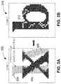
- FIGS. 3A and 3Bare schematics illustrating the formation of light edge artifacts in images displayed on an electro-optic display.
- FIG. 4is an exemplary waveform used to regenerate a black optical state in an exemplary method of operating an electro-optic display.
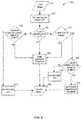
- FIG. 5is a flowchart illustrating an exemplary method of operating an electro-optic display, according to some embodiments of the present invention.
- FIG. 6is a flowchart illustrating an exemplary method of operating an electro-optic display, according to some embodiments of the present invention.
- FIG. 7is a flowchart illustrating an exemplary method of operating an electro-optic display, according to some embodiments of the present invention.
- FIG. 8Ais an exemplary image of text displayed without correction for light edge artifacts.
- FIG. 8Bis an exemplary image of text displayed with correction for light edge artifacts, according to the subject matter presented herein.
- FIG. 9is a plot of simulated remnant voltage across an electro-optic display.
- FIG. 10Ais an electro-optic display showing a checker board like pattern.
- FIG. 10Bis an electro-optic display showing another checker board like pattern.
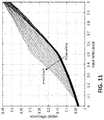
- FIG. 11is a plot of measured output reflectance versus input reflectance.
- FIG. 12A and FIG. 12Bare input images to be displayed on an electro-optic display.
- FIG. 12Cis a resulting image after an electro-optic display has been updated with the images of FIG. 12A and FIG. 12B .
- FIG. 13A to FIG. 13Dare embodiments of driving waveforms that are in accordance with the disclosures presented herein.
- FIG. 14is a plot of measured output reflectance versus input reflectance using the waveforms presented in FIG. 13A to FIG. 13D .
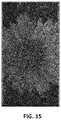
- FIG. 15is a resulting image after an electro-optic display has been updated using the waveforms presented in FIG. 13A to FIG. 13D .
- FIG. 16is a table illustrating a set of parameters to be used for estimating pixel blooming in accordance with the subject matter presented herein.
- FIG. 17is a model illustrating one embodiment of a dithering process in accordance with the subject matter disclosed herein.
- edge artifactis the appearance of light edges in dark regions, such as in the body of text characters displayed in white mode where the text is in a black state and the background is in a white state.
- This type of artifactcan arise when a display is driven using techniques to reduce the flashiness of the display by not applying voltage signals (or zero voltage) to pixels that remain in the same state from one image to a subsequent image, which may be considered as a “null state transition.”
- optical propertyis typically color perceptible to the human eye, it may be another optical property, such as optical transmission, reflectance, luminescence or, in the case of displays intended for machine reading, pseudo-color in the sense of a change in reflectance of electromagnetic wavelengths outside the visible range.
- gray stateis used herein in its conventional meaning in the imaging art to refer to a state intermediate two extreme optical states of a pixel, and does not necessarily imply a black-white transition between these two extreme states.
- E Ink patents and published applications referred to abovedescribe electrophoretic displays in which the extreme states are white and deep blue, so that an intermediate “gray state” would actually be pale blue. Indeed, as already mentioned, the change in optical state may not be a color change at all.
- black and “white”may be used hereinafter to refer to the two extreme optical states of a display, and should be understood as normally including extreme optical states which are not strictly black and white, for example the aforementioned white and dark blue states.
- the term “monochrome”may be used hereinafter to denote a drive scheme which only drives pixels to their two extreme optical states with no intervening gray states.
- gray stateAs the discussion below will focus on methods for driving one or more pixels of an electro-optic display through a transition from an initial gray level (or “graytone”) to a final gray level (which may or may not be different from the initial gray level).
- gray stateAs the number of possible gray levels in current systems is typically 2-16 due to limitations such as discreteness of driving pulses imposed by the frame rate of the display drivers and temperature sensitivity.
- gray level 1is black and gray level 16 is white; however, the black and white gray level designations may be reversed.
- graytone 1will be used to designate black.
- Graytone 2will be a lighter shade of black as the graytones progress towards graytone 16 (i.e., white).
- bistable and “bistability”are used herein in their conventional meaning in the art to refer to displays comprising display elements having first and second display states differing in at least one optical property, and such that after any given element has been driven, by means of an addressing pulse of finite duration, to assume either its first or second display state, after the addressing pulse has terminated, that state will persist for at least several times, for example at least four times, the minimum duration of the addressing pulse required to change the state of the display element.
- addressing pulseof finite duration
- some particle-based electrophoretic displays capable of gray scaleare stable not only in their extreme black and white states but also in their intermediate gray states, and the same is true of some other types of electro-optic displays.
- This type of displayis properly called “multi-stable” rather than bistable, although for convenience the term “bistable” may be used herein to cover both bistable and multi-stable displays.
- impulseis used herein in its conventional meaning of the integral of voltage with respect to time.
- bistable electro-optic mediaact as charge transducers, and with such media an alternative definition of impulse, namely the integral of current over time (which is equal to the total charge applied) may be used.
- the appropriate definition of impulseshould be used, depending on whether the medium acts as a voltage-time impulse transducer or a charge impulse transducer.
- the term “remnant voltage”is used herein to refer to a persistent or decaying electric field that may remain in an electro-optic display after an addressing pulse (a voltage pulse used to change the optical state of the electro-optic medium) is terminated. Such remnant voltages can lead to undesirable effects on the images displayed on electro-optic displays, including, without limitation, so-called “ghosting” phenomena, in which, after the display has been rewritten, traces of the previous image are still visible.
- the application 2003/0137521describes how a direct current (DC) imbalanced waveform can result in a remnant voltage being created, this remnant voltage being ascertainable by measuring the open-circuit electrochemical potential of a display pixel.
- waveformwill be used to denote the entire voltage against time curve used to effect the transition from one specific initial gray level to a specific final gray level.
- a waveformwill comprise a plurality of waveform elements; where these elements are essentially rectangular (i.e., where a given element comprises application of a constant voltage for a period of time); the elements may be called “pulses” or “drive pulses”.
- drive schemedenotes a set of waveforms sufficient to effect all possible transitions between gray levels for a specific display.
- a displaymay make use of more than one drive scheme; for example, the aforementioned U.S. Pat. No.
- a drive schememay need to be modified depending upon parameters such as the temperature of the display or the time for which it has been in operation during its lifetime, and thus a display may be provided with a plurality of different drive schemes to be used at differing temperature etc.
- a set of drive schemes used in this mannermay be referred to as “a set of related drive schemes.” It is also possible, as described in several of the aforementioned MEDEOD applications, to use more than one drive scheme simultaneously in different areas of the same display, and a set of drive schemes used in this manner may be referred to as “a set of simultaneous drive schemes.”
- electro-optic displaysare known.
- One type of electro-optic displayis a rotating bichromal member type as described, for example, in U.S. Pat. Nos. 5,808,783; 5,777,782; 5,760,761; 6,054,071 6,055,091; 6,097,531; 6,128,124; 6,137,467; and 6,147,791 (although this type of display is often referred to as a “rotating bichromal ball” display, the term “rotating bichromal member” is preferred as more accurate since in some of the patents mentioned above the rotating members are not spherical).
- Such a displayuses a large number of small bodies (typically spherical or cylindrical) which have two or more sections with differing optical characteristics, and an internal dipole. These bodies are suspended within liquid-filled vacuoles within a matrix, the vacuoles being filled with liquid so that the bodies are free to rotate. The appearance of the display is changed by applying an electric field thereto, thus rotating the bodies to various positions and varying which of the sections of the bodies is seen through a viewing surface.
- This type of electro-optic mediumis typically bistable.
- electro-optic displayuses an electrochromic medium, for example an electrochromic medium in the form of a nanochromic film comprising an electrode formed at least in part from a semi-conducting metal oxide and a plurality of dye molecules capable of reversible color change attached to the electrode; see, for example O'Regan, B., et al., Nature 1991, 353, 737; and Wood, D., Information Display, 18(3), 24 (March 2002). See also Bach, U., et al., Adv. Mater., 2002, 14(11), 845. Nanochromic films of this type are also described, for example, in U.S. Pat. Nos. 6,301,038; 6,870,657; and 6,950,220. This type of medium is also typically bistable.
- electro-optic displayis an electro-wetting display developed by Philips and described in Hayes, R. A., et at, “Video-Speed Electronic Paper Based on Electrowetting”, Nature, 425, 383-385 (2003). It is shown in U.S. Pat. No. 7,420,549 that such electro-wetting displays can be made bistable.
- Electrophoretic displayscan have attributes of good brightness and contrast, wide viewing angles, state bistability, and low power consumption when compared with liquid crystal displays. Nevertheless, problems with the long-term image quality of these displays have prevented their widespread usage. For example, particles that make up electrophoretic displays tend to settle, resulting in inadequate service-life for these displays.
- electrophoretic mediarequire the presence of a fluid.
- this fluidis a liquid, but electrophoretic media can be produced using gaseous fluids; see, for example, Kitamura, T., et al., “Electrical toner movement for electronic paper-like display”, IDW Japan, 2001, Paper HCS1-1, and Yamaguchi, Y., et al., “Toner display using insulative particles charged triboelectrically”, IDW Japan, 2001, Paper AMD4-4). See also U.S. Pat. Nos. 7,321,459 and 7,236,291.
- Such gas-based electrophoretic mediaappear to be susceptible to the same types of problems due to particle settling as liquid-based electrophoretic media, when the media are used in an orientation which permits such settling, for example in a sign where the medium is disposed in a vertical plane. Indeed, particle settling appears to be a more serious problem in gas-based electrophoretic media than in liquid-based ones, since the lower viscosity of gaseous suspending fluids as compared with liquid ones allows more rapid settling of the electrophoretic particles.
- encapsulated electrophoretic and other electro-optic mediacomprise numerous small capsules, each of which itself comprises an internal phase containing electrophoretically-mobile particles in a fluid medium, and a capsule wall surrounding the internal phase.
- the capsulesare themselves held within a polymeric binder to form a coherent layer positioned between two electrodes.
- the technologies described in the these patents and applicationsinclude:
- the walls surrounding the discrete microcapsules in an encapsulated electrophoretic mediumcould be replaced by a continuous phase, thus producing a so-called polymer-dispersed electrophoretic display, in which the electrophoretic medium comprises a plurality of discrete droplets of an electrophoretic fluid and a continuous phase of a polymeric material, and that the discrete droplets of electrophoretic fluid within such a polymer-dispersed electrophoretic display may be regarded as capsules or microcapsules even though no discrete capsule membrane is associated with each individual droplet; see for example, the aforementioned U.S. Pat. No. 6,866,760. Accordingly, for purposes of the present application, such polymer-dispersed electrophoretic media are regarded as sub-species of encapsulated electrophoretic media.
- microcell electrophoretic displayA related type of electrophoretic display is a so-called “microcell electrophoretic display”.
- the charged particles and the fluidare not encapsulated within microcapsules but instead are retained within a plurality of cavities formed within a carrier medium, typically a polymeric film. See, for example, U.S. Pat. Nos. 6,672,921 and 6,788,449, both assigned to Sipix Imaging, Inc.
- electrophoretic mediaare often opaque (since, for example, in many electrophoretic media, the particles substantially block transmission of visible light through the display) and operate in a reflective mode
- many electrophoretic displayscan be made to operate in a so-called “shutter mode” in which one display state is substantially opaque and one is light-transmissive. See, for example, U.S. Pat. Nos. 5,872,552; 6,130,774; 6,144,361; 6,172,798; 6,271,823; 6,225,971; and 6,184,856.
- Dielectrophoretic displayswhich are similar to electrophoretic displays but rely upon variations in electric field strength, can operate in a similar mode; see U.S. Pat. No. 4,418,346.
- Electro-optic media operating in shutter modemay be useful in multi-layer structures for full color displays; in such structures, at least one layer adjacent the viewing surface of the display operates in shutter mode to expose or conceal a second layer more distant from the viewing surface.
- An encapsulated electrophoretic displaytypically does not suffer from the clustering and settling failure mode of traditional electrophoretic devices and provides further advantages, such as the ability to print or coat the display on a wide variety of flexible and rigid substrates.
- printingis intended to include all forms of printing and coating, including, but without limitation: pre-metered coatings such as patch die coating, slot or extrusion coating, slide or cascade coating, curtain coating; roll coating such as knife over roll coating, forward and reverse roll coating; gravure coating; dip coating; spray coating; meniscus coating; spin coating; brush coating; air knife coating; silk screen printing processes; electrostatic printing processes; thermal printing processes; ink jet printing processes; electrophoretic deposition (See U.S. Pat. No. 7,339,715); and other similar techniques.)
- pre-metered coatingssuch as patch die coating, slot or extrusion coating, slide or cascade coating, curtain coating
- roll coatingsuch as knife over roll coating, forward and reverse roll coating
- gravure coatingdip coating
- spray coatingmeniscus coating
- spin coatingbrush
- electro-optic mediamay also be used in the displays of the present invention.
- LC displaysThe bistable or multi-stable behavior of particle-based electrophoretic displays, and other electro-optic displays displaying similar behavior (such displays may hereinafter for convenience be referred to as “impulse driven displays”), is in marked contrast to that of conventional liquid crystal (“LC”) displays. Twisted nematic liquid crystals are not bi- or multi-stable but act as voltage transducers, so that applying a given electric field to a pixel of such a display produces a specific gray level at the pixel, regardless of the gray level previously present at the pixel. Furthermore, LC displays are only driven in one direction (from non-transmissive or “dark” to transmissive or “light”), the reverse transition from a lighter state to a darker one being effected by reducing or eliminating the electric field.
- bistable electro-optic displaysact, to a first approximation, as impulse transducers, so that the final state of a pixel depends not only upon the electric field applied and the time for which this field is applied, but also upon the state of the pixel prior to the application of the electric field.
- the electro-optic medium usedis bistable, to obtain a high-resolution display, individual pixels of a display must be addressable without interference from adjacent pixels.
- One way to achieve this objectiveis to provide an array of non-linear elements, such as transistors or diodes, with at least one non-linear element associated with each pixel, to produce an “active matrix” display.
- An addressing or pixel electrode, which addresses one pixel,is connected to an appropriate voltage source through the associated non-linear element.
- the non-linear elementis a transistor
- the pixel electrodeis connected to the drain of the transistor, and this arrangement will be assumed in the following description, although it is essentially arbitrary and the pixel electrode could be connected to the source of the transistor.
- the pixelsare arranged in a two-dimensional array of rows and columns, such that any specific pixel is uniquely defined by the intersection of one specified row and one specified column.
- the sources of all the transistors in each columnare connected to a single column electrode, while the gates of all the transistors in each row are connected to a single row electrode; again the assignment of sources to rows and gates to columns is conventional but essentially arbitrary, and could be reversed if desired.
- the row electrodesare connected to a row driver, which essentially ensures that at any given moment only one row is selected, i.e., that there is applied to the selected row electrode a voltage such as to ensure that all the transistors in the selected row are conductive, while there is applied to all other rows a voltage such as to ensure that all the transistors in these non-selected rows remain non-conductive.
- the column electrodesare connected to column drivers, which place upon the various column electrodes voltages selected to drive the pixels in the selected row to their desired optical states.
- the aforementioned voltagesare relative to a common front electrode which is conventionally provided on the opposed side of the electro-optic medium from the non-linear array and extends across the whole display.) After a pre-selected interval known as the “line address time” the selected row is deselected, the next row is selected, and the voltages on the column drivers are changed so that the next line of the display is written. This process is repeated so that the entire display is written in a row-by-row manner.
- Voltage signals applied to neighboring pixelscan impact the optical state of the null state pixels, forming artifacts that can be carried to subsequent images.
- a voltage signalmay not be applied to a pixel that remains as part of a text character from one image to a subsequent image because it undergoes a black state to black state transition (B ⁇ B). This may reduce flashiness of the display by applying voltage signals only to pixels that change state between subsequent images. Although flashiness may be reduced, light edge artifacts can arise by such a drive scheme.
- voltage signals applied to neighboring pixelsmay affect the optical state of the null state pixel, such as by impacting the distribution of electrophoretic medium of the pixel undergoing the null state transition and creating an undesired change in its optical state.
- a pixel identified to remain in a black state during a transitionmay have a lighter optical state because of one or more neighboring pixels undergoing a black state to white state transition.
- Pixels having a lighter optical statemay become surrounded by pixels displaying a black optical state in a subsequent image transition, forming light edge artifacts in the image that may be more apparent to a viewer of the display than if the light pixels are on the edge of an object. Accordingly, aspects of the present application relate to identifying pixels that are likely to negatively impact the visual aesthetics of the content displayed based on prior transitions of pixel neighboring the pixel of interest, and applying suitable corrective signals when appropriate to reduce or eliminate such negative impact.
- the waveformmay be a voltage signal configured to regenerate an optical black state of a pixel that has, or may, become lighter because of voltage signals applied to neighboring pixels, such as through blooming Regenerating an optical black state of the pixel may reduce the appearance of light edges that can occur when a pixel is transitioning from a non-black state to a black state and a neighboring pixel that has undergone a black state to black state transition.
- the waveformmay include a voltage signal with amplitude and a duration or time suitable for generating a desired optical state.
- the voltage signalmay be applied over multiple display frames to achieve the desired optical state of the pixel.
- suitable waveformsincluding a transition waveform referred to as an inverted top-off pulse (“iTop pulse”), are described in aforementioned U.S. patent application Ser. No. 15/015,822 filed Feb. 4, 2016, which is incorporated herein by reference in its entirety.
- aspects of the present applicationrelate to methods for selectively applying the waveform to pixels in a manner that suitably balances reducing the appearance of light edge artifacts and the frequency at which the waveform is applied.
- a drive scheme for an electro-optic displaymay include identifying pixels undergoing a null state transition where the optical state of the pixels is likely to have been affected by the transitions of neighboring pixels.
- a waveform for regenerating an optical state of a null state pixelmay be applied when neighboring pixels have undergone transitions that may impact the optical state of the null state pixel.
- the driving schememay apply a waveform for regenerating an optical black state to a pixel designated to remain in a black state when neighboring pixels undergo transitions that may result in a lighter optical state of the pixel.
- the waveformis applied to a pixel when one or more cardinal neighbors of the pixel undergo a white state to a black state transition between subsequent images.
- the waveformis applied to a pixel when one or more cardinal neighbors have a subsequent black state.
- Display 100includes art electrophoretic medium layer 101 which may comprise a plurality of capsules 104 each having a capsule wall surrounding fluid and electrophoretic particles 106 suspended in the fluid.
- the electrophoretic medium layer 101is between electrode 102 and pixelated electrodes 110 a , 110 b , 110 c , which define pixels of display 100 .
- the electrophoretic particles 106may be electrically charged and responsive to an electric field created by electrode 102 and one of electrodes 110 a , 110 b , 110 c . Examples of suitable electrophoretic medium layers are described in U.S. Pat. Nos. 6,982,178 and 7,513,813, which are incorporated herein by reference in their entireties.
- the display 100also includes a voltage source 108 coupled to the electrodes and configured to provide a drive signal to those electrodes.
- FIG. 1shows coupling of the voltage source 108 between electrodes 102 and 110 a
- voltage source 108may couple with electrodes 110 b and 110 c to provide drive signals to multiple pixels of display 100 .
- the provided voltagethen creates an electric field between the electrode 102 and one or more electrodes 110 a , 110 b , 110 c .
- the electric field experienced by the electrophoretic medium layer 101may be controlled by varying the voltage applied to the electrode 102 and one or more electrodes 110 a , 110 b , 110 c . Varying the voltages applied to the desired pixels may provide control over the pixels of the display.
- Particles 106 within the electrophoretic medium layer 101may move within their respective capsules 104 in response to the applied electric field created by the voltage between electrode 102 and electrodes 110 a , 110 b , 110 c .
- the grayscale of the optical state of a pixelcan be controlled.
- Voltage source 108may couple to display controller 112 .
- Display controller 112may include drive circuitry configured to perform a method of operating display 100 .
- Display controller 112may include a memory configured to store the states of one or more the pixels of display 100 . Current and/or prior states of the pixels may be stored in the memory of display controller 112 in any suitable manner.
- FIG. 1illustrates a microcapsule type electrophoretic display
- various types of displaysmay be used according the techniques described in the present application.
- electro-optic displaysincluding microcapsule type electrophoretic displays, microcell type electrophoretic displays, and polymer dispersed electrophoretic image displays (PDEPIDs) may utilize aspects of the present application.
- electrophoretic displaysrepresent a suitable type of display according to aspects of the present application
- other types of displaysmay also utilize one or more aspects of the present application.
- Gyricon displays, electrochromic displays, and polymer dispersed liquid crystal displays (PDLCD)may also take advantage of aspects of the present application.
- Pixels of an electrophoretic displaymay be driven to different optical states depending on the voltage signals applied.
- the voltage signal used to obtain an optical state of a pixelmay depend on the previous optical state of the pixel.
- the voltage signalmay include negative and/or positive voltage.
- positive voltagesare identified on the y-axis as Vpos and negative voltages as Vneg.
- a waveform having a negative voltagesuch as the waveform 201 shown in FIG. 2A , may drive a pixel of an electrophoretic display from a black state to a white state.
- a waveform having a positive voltagemay drive a pixel of an electrophoretic display from a white state to a black state.
- the x-axisrepresents time and the y-axis represents voltage.
- an electrophoretic displaymay be driven to another grayscale level, using only two gray levels may simplify the number and complexity of waveforms to use in driving the pixels to transition between different optical states.
- Two gray levelsmay be particularly suited in displays with a higher resolution (e.g., greater than 300 dpi, greater than 500 dpi, between 300 dpi and 800 dpi, or any value or range of values within such ranges) because of the ability to present text to a viewer with a desired level of quality.
- Techniques for reducing light edge artifacts as described hereinmay be applied to electrophoretic displays driven at two gray levels (e.g., a white state and a black state) because of the crosstalk between neighboring pixels.
- a voltage signal applied to a pixelmay impact a portion of the neighboring pixel, such as approximately one-fifth of the neighboring pixel.
- Crosstalk between pixelsmay result in blooming events when a pixel undergoing a null transition has an optical state impacted by a neighboring pixel.
- FIG. 3Adepicts a first image 302 (Image 1 ) that includes the letter “x” representing pixels that are currently in a black state. It is here assumed that a previous image to Image 1 included the letter “l” 304 and a portion of the letter “y” 306 , which is shown by the downward diagonal line regions of FIG. 3A . Pixels of the letter “x” that overlap with the letters “l” 304 and “y” 306 of the previous image experienced a black state to black state transition since, in this example, the display is operating with letters as black with a white background.
- pixels of the letters “l” 304 and “y” 306 that do not overlap with the letter “x”underwent a black state to white state transition to create the white background surrounding the letter “x.” Although the letters “l” and “y” were displayed in the previous image, they are shown in FIG. 3A to illustrate the overlap between pixels of the letter “x” with the letters “l” 304 and “y” 306 of the previous image.
- a pixel undergoing a null transitionmay experience a blooming event by the presence of voltage signals applied to one or more neighboring pixels.
- An exampleis pixel 308 .
- the pixels of the letter “x” that neighbor one or more of the pixels that underwent a black state to white state transition, such as pixel 308may experience a blooming event and appear lighter than an optical black state. Such pixels are indicated by the dark gray regions within the letter “x.” In the resulting image 1 shown in FIG. 3A , the pixels of the letter “x” that appear less dark are positioned at the edge of the text and border a pixel that experienced a black to white transition.
- pixels of the letter “x”underwent a white state to black state transition. These pixels are ones that do not overlap with the letters “l” 304 and “y” 306 and may appear darker than the pixels of the letter “x” which neighbor pixels that underwent a black to white transition.
- FIG. 3Billustrates image 310 (Image 2 ) that includes the letter “b” which has pixels that overlap with the letter “x” of image 1 which underwent a null transition by remaining in a black state. Since some of the pixels of the letter “x” appeared in a lighter optical state due to blooming, this lighter appearance of these pixels is present in the current image of letter “b,” an example being pixel 312 . These lighter pixels create regions that appear less dark compared to other black pixels. Such light pixels may create the appearance of light “edges” or “lines” within the image and reduce the quality of the image.
- Some embodiments of the present applicationrelate to operating an electrophoretic display in a manner that reduces the appearance of light edges within a displayed image, such as those shown in FIG. 3B by pixels 312 .
- Operation of an electrophoretic displaymay include selectively applying a voltage signal to pixels that may contribute to the presence of light edges, such as to pixels 312 . Whether a pixel may contribute to light edge artifacts may be determined by previous transitions of the pixel and one or more pixels that neighbor the pixel in question. In a driving scheme in which voltages are not applied to pixels undergoing null state transitions, such pixels may be the most likely to contribute to the appearance of light edge artifacts.
- Such a pixelmay experience a blooming event when voltage signals applied to one or more neighboring pixels alter the optical state of the pixel in question.
- the number of neighboring pixelsmay impact the degree of a blooming event for the pixel, affecting the optical state of the pixel.
- a pixelmay have up to four cardinal neighboring pixels.
- a moderate blooming eventmay occur when one cardinal neighbor undergoes a black to white transition.
- a strong blooming eventmay occur when all four cardinal neighboring pixels undergo a black to white transition.
- a pixel experiencing the strong blooming eventmay appear lighter than the moderate blooming event.
- the effect of the blooming eventcan be reduced by applying a voltage signal to the pixel in question to generate an optical state of the pixel (e.g., a black optical state). While applying the voltage signal may reduce the appearance of bloomed pixels, applying the voltage signal too frequently may damage the electrophoretic display.
- the voltage signalmay be a DC-imbalanced waveform and may result in the buildup of remnant voltage in the display over time as the waveform is applied.
- Some embodiments of the present applicationrelate to detecting whether a pixel experiences a null transition, determining whether a threshold number of cardinal neighbors of the pixel transition from a black state to a white state during an image transition, and applying a voltage signal to the pixel in a subsequent image transition.
- the voltage signalmay have a waveform configured to generate an optical black state of the pixel.
- the type of transition to apply to a pixelmay be determined by one or more previous waveform states of the pixel and/or other pixels of the display.
- a current state of a pixelmay determine the type of waveform to apply to the pixel to change or alter the optical state of the pixel.
- a waveform statemay correspond to a desired optical state of the pixel.
- Prior and/or current states of the pixels in the displaymay be stored in a display controller, or other suitable circuitry configured to perform a method of operating the display, and allow for determining an appropriate subsequent transition based on a prior or current state of a pixel.
- Techniques of the present applicationrelate to associating an indication state (or I state) to a pixel likely to have experienced a blooming event, and which therefore may be prone to appearing as a light pixel in subsequent images if no refresh, or corrective, signal is applied.
- a pixelmay assume, or be assigned, an indication state when the pixel undergoes a black state to black state transition and one or more neighboring pixels undergoes a black state to white state transition. These conditions may identify pixels that have experienced a blooming event.
- Application of a voltage signal suitable to generate an optical black state in the identified “indication state” pixelmay be applied in a subsequent transition to reduce the presence of light edge artifacts.
- the indication statemay refer to a pixel that should have a black optical state, but may not appear completely dark because of blooming events from neighboring pixels.
- pixel 308may be set to an indication state because it remained in a black state and had one or more neighboring pixels that underwent a black to white transition. Such pixels in FIG. 3A contributed to the light edges that appeared in the letter “b” in FIG. 3B , such as pixel 312 .
- a voltage signalmay be applied to a pixel in an indication state (I state) to generate an optical black state for the pixel and may be referred to as a “black regeneration waveform,” according to some embodiments.
- the voltage signalmay have a positive voltage value (e.g., Vpos) over a duration of time, the voltage assuming any suitable value.
- An exemplary voltage signal used to generate an optical black stateis shown in FIG. 4 as waveform 402 .
- the voltage signalmay be applied over multiple display frames to achieve the desired result.
- the waveformmay be referred to as an inverted top-off pulse (iTop pulse).
- a method of operating an electro-optic displaymay include detecting a null state transition for one or more pixels and determining whether a threshold number of cardinal neighbors underwent a black state to white state transition between a first image and a second image.
- first and secondin this context is not limited to an absolute value, but rather are meant to indicate a preceding image and subsequent image.
- a “third” imageis not an absolute value but indicates an image subsequent to a “second” image and there may be intervening images between a “second” image and a “third” image.
- the voltage signal or iTop pulsemay be applied to a pixel in an indication state when a subsequent state is a black state.
- Method 500may start with first image 510 , such as the image prior to Image 1 in FIG. 3A showing the “l” 304 and “y” 306 .
- First image 510may have a set of states for the pixels of the display, which may be stored in a display controller, such as display controller 112 in FIG. 1 .
- second image datais received, such as by display controller 112 .
- the second image datamay include optical states of the pixels in the display in order to display the second image, such as Image 1 in FIG. 3A displaying the letter “x,”
- method 500proceeds to act 530 . If the current state of the pixel is in neither a black (B) state nor an indication (I) state, then a standard transition used to operate the electrophoretic display is applied by act 560 in displaying the second image by act 580 .
- act 540examines the transitions of the pixel's cardinal neighbors to determine whether one or more of the cardinal neighbors is undergoing a black (B) state to white (W) state transition from the first image to the second image.
- act 540may include determining whether a threshold number (e.g., 1, 2, 3, 4) of cardinal neighbors of the pixel transition from a black state to a white state.
- the standard transition used to operate the electrophoretic displayis applied by act 560 in displaying the second image by act 580 . If, by contrast, there is one or more cardinal neighbors experiencing a black state to white state transition or if the number of cardinal neighbors experiencing a black state to white state transition is above a threshold, then the state of the pixel is set to an indication (I) state by act 570 to form the second image by act 580 . In this manner, the pixel is identified as potentially experiencing a blooming event by one or more of its cardinal neighbors.
- method 500proceeds to act 550 , which determines the next state of the pixel from the data of the second image. If the next state of the pixel is not the black state (e.g., white state), then the standard transition used to operate the electrophoretic display is applied by act 560 in displaying the second image by act 580 . If the next state of the pixel is the black (B) state, then a black regeneration waveform, such as the one depicted in FIG. 4 , is applied to the pixel by act 590 in displaying the second image by act 580 .
- a black regeneration waveformsuch as the one depicted in FIG. 4
- the black regeneration waveformis applied to those pixels identified as likely to have experienced a blooming event as indicated by being in the indication (I) state.
- Acts 550 and 590may occur, for example, for pixel 308 when going from Image 1 of FIG. 3A to Image 2 of FIG. 3B .
- FIG. 6shows steps of method 600 according to another embodiment, which includes additional steps to those of method 500 shown in FIG. 5 . These additional steps provide further selection over when the black regeneration waveform is applied in act 590 .
- a pixel that has a current state as an indication (I) state by act 530 and a next state as the black (B) state by act 550proceeds to step 610 of method 600 , which examines the type of transition for one or more cardinal neighbors of the pixel in transitioning to the second image.
- the black regeneration waveformis applied to the pixel by act 590 in displaying the second image by act 580 .
- the black regeneration waveformis applied to the pixel. If the pixel does not meet the conditions of act 610 where there are no cardinal neighbors transitioning from a white (W) state to a black (B) state or the number of cardinal neighbors undergoing such a transition is below a threshold, then the pixel is set to the indication (I) state by act 620 .
- the pixelmay receive the black regeneration waveform when one or more cardinal neighbors transition to a black state to reduce the likelihood of a lighter pixel next to a darker pixel and therefore the visibility of light edge artifacts to a viewer of the displayed second image.
- FIG. 7shows alternative steps that may be implemented in operating an electro-optic display.
- Method 7includes additional steps to those of method 500 shown in FIG. 5 . These additional steps provide further selection over when the black regeneration waveform is applied in act 590 .
- a pixel that has a current state as an indication (I) state by act 530 and a next state as the black (B) state by act 550proceeds to step 710 of method 700 , which examines the next state for one or more cardinal neighbors of the pixel in the second image. If one or more cardinal neighbors have a next state as a black (B) state, then the black regeneration waveform is applied to the pixel by act 590 in displaying the second image by act 580 .
- the black regeneration waveformis applied to the pixel by act 590 . If the pixel does not meet the conditions of act 710 where there are no cardinal neighbors that have a next state as a black (B) state or the number of cardinal neighbors transitioning to a black state is below a threshold, then the pixel is set to the indication (I) state by act 720 .
- Method 700provides an alternative method for selectively applying the black regeneration waveform to pixels in reducing the presence of light edge artifacts in images displayed on the electro-optic display.
- FIG. 8Ashows an example image of text displayed on an electro-optic display where such light edge correction is not used. The appearance of lighter regions in the text, particularly in the letters “v” and “j,” is present.
- FIG. 8Bshows an example image of the same text shown on an electro-optic display operated in a manner described herein to reduce the presence of such light edge artifacts.
- a voltage signal used to regenerate the black optical state of the pixelmay be DC-imbalanced and create irreversible damage to the display arising from the buildup of remnant voltage in the display.
- Techniques of the present applicationrelate to methods of applying the waveform selectively to reduce the buildup of remnant voltage and damage to the display.
- FIG. 9illustrates a plot of simulated remnant voltage across a display for the display usage scenario of displaying 4500 subsequent images (e.g., pages of text) on the display using a light edge correction operation method according to the techniques described herein for different types of black regeneration waveforms with reference to a null state transition waveform 902 .
- the black regeneration waveform 904includes 21 frames of a +15V drive signal, then such a waveform could create a remnant voltage at a pixel of the display to exceed 2.5 V, which would likely damage the display.
- the black regeneration waveform 906includes 6 frames of a +15 V drive signal with a padding of 4 frames, then such a waveform could create a remnant voltage at a pixel less than 0.5V, which may be considered a suitable amount of remnant voltage to reduce damage to the display.
- FIGS. 10A and 10Bare two checker board like image patterns for illustrating the differences in blooming (or differential blooming) depending on whether the prior displayed image is solid black or solid white and whether the EPD is updated using a so called direct-update (DU) waveform.
- the DU waveformupdates the EPD in such a fashion that the EPD pixels going through black to white and white to black transitions receive a single pulse of driving where a typical pulse has a duration of about 250 ms.
- Waveforms presented in FIGS. 2A and 2Bmay be adopted as DU waveforms in some embodiments.
- the DU waveformis characterized as a 1-bit waveform. Accordingly, as illustrated in FIG. 10A , the pixels going through a black to black transition received a null waveform while their neighboring pixels going through black to white transitions received a DU waveform. Similarly, in FIG. 10B , pixels that remained from white to white received a null waveform while their neighboring pixels going through a white to black transition received DU waveforms.
- crosstalk between pixelscan lead to optical artifacts (i.e., blooming) where pixels bloom over and into their neighbors.
- optical artifactsi.e., blooming
- Differential bloomingoccurs when blooming characteristics differ depending on the prior image being displayed by the EPD's pixels, as can be appreciated by a comparison of FIGS. 10A and 10B , where the average reflectance of the black and white checker board is much lighter when the prior image is black compared to when the prior image is white.
- FIG. 11is a plot of measured output reflectance versus input reflectance from 32 different prior states linearly spaced in reflectance between pure black and pure white.
- the prior stateis a gray-tone that is rendered by 1-bit dithering using dispersed dot ordered dither.
- the prior state for the mid gray-tonemay be a checkerboard with 50% black and 50% white pixels where each square is a single pixel.
- the EPDis updated with DU to another gray-tone referred to as the input reflectance.
- This input reflectancecorresponds to the desired gray-tone to be displayed.
- the input reflectanceranges from 0 to 1 where 0 is solid black and 1 is solid white.
- the output reflectanceis the measured reflectance on the display from the final image.
- Such curvesare referred to as the tone reproduction curves (TRC).
- TRCtone reproduction curves
- the TRCvaries significantly depending on the prior state mainly due to the differential blooming.
- the level of differential blooming illustrated in FIG. 11can lead to significant image ghosting (e.g., up to 10 L* in image quality), as shown in FIG. 12C , where FIG. 12A is the first input image and FIG. 12B is a subsequent image to be displayed on the EPD.
- image ghostinge.g., up to 10 L* in image quality
- this ghosting effectmay be significantly reduced by setting the EPD pixels to an original or starting optical state, for example, solid white.
- an EPDmay be conveniently updated with DU waveforms where the update time is swift (e.g., 250 ms).
- the update waveformmay be designed such that all the pixels go to white first before going their final states. As a result, the blooming will always be the same for all pixels no matter where they came from, which effectively eliminates differential blooming.
- a drive waveformcan be configured such that all the pixels finish their transitions to white before any pixels start transitions to black, and each phase or transitions of the waveforms are aligned temporally (e.g., the transitions of the waveforms start and end at the same time). Specifically, for this setup, all the pixels finish their transition to white before any pixel starts transitioning to black. In practice, it will look like a white page is inserted in the middle of any transition from an image to another image. It also results in a transition appearance that may be described as “clean” or “calming” as opposed to “flashy” for typical GC waveforms. This will enable 1-bit usage in EPDs with reasonable ghosting performance.
- FIGS. 13A to 13Dillustrate exemplary 1-bit waveforms for four active transitions: black to white ( FIG. 13A ), black to black ( FIG. 13B ), white to black ( FIG. 13C ), and white to white ( FIG. 13D ).
- the waveformscan include 6 tunable waveform parameters: pl 1 BB , pl 2 BB , pl 1 BW , pl 2 WB , gap and padding.
- the parameters pl 1 BB and pl 1 BWcorrespond to the pulse lengths for the drives to white for the black to black and black to white transitions; the parameters pl 2 BB and pl 2 WB correspond to the pulse lengths for the drives to black for the black to black and white to black transitions.
- the gap parametercorresponds to the gap in time between the end of the last drive to white (for either the black to black or black to white transitions) and the beginning of the first drive to black (for either the black to black or white to black transitions).
- the gap parametermay vary from 0 to 100 ms in duration.
- the padding parametercorresponds to the time between the last drive to black and the end of the waveform, and it may also vary from 0 to 100 ms in duration.
- the waveform transitionsare aligned in order to create a very clean transition appearance. In FIGS.
- the waveformis shown to be left-aligned which means that the drives to white and the drives to black all start at the same time. However, it may also be possible for the waveform to be right-aligned, meaning that the drives to white and the drives to black all end at the same time.
- the white to white transitionis empty to further reduce the waveform flashiness and enable the clean transition appearance.
- These waveformsmay be integrated with the other driving algorithms or schemes (e.g., EInk Regal algorithms) for better performances and avoid edge accumulation with this scheme.
- the white to white pixelsmay either receive a null waveform or the T or F transitions as determined by the Regal algorithm. The T transition is to be properly placed such that it is positioned within the drives to white.
- the parameters described abovemay be further tuned to meet various design goals, such as minimizing the waveform area ghosting and blooming, as well as optimize display reliabilities. Certain parameter combinations may lead to significant DC-imbalance experienced by the display in usage. It is therefore preferred to control the amount of DC-imbalance introduced by this waveform in order to ensure long-term reliability and avoid display performance degradation over time. This waveform concept results in significant reduction in differential blooming as illustrated in FIG. 14 .
- FIG. 16is a table of parameters for a dithering model that can be used to: (1) progressively model the local blooming at each display pixel, and (2) modify error diffusion algorithms which uses the model to dither the image appropriately.
- an estimate of the current optical impact of the bloomingis kept for each pixel edge in the image. Since there are twice as many edges as pixels, it is convenient to keep two display-sized (in number of pixels) arrays in memory to hold this information. For our purposes we will call them bloomUp and bloomLeft which hold the estimate of the optical effect caused by blooming with the upward neighbor and leftward neighbor of the associated pixel respectively. If the previous state and current state of the display is known, then the next bloomUp and bloomLeft arrays can be updated by examining each pixel pair across the specified edge (Up or Left) and replacing the value with that computed in the table illustrated in FIG. 16 .
- the parameters ⁇ K and ⁇ Ware effective blooming width (EBW) scores (for black and white pixels respectively) derived from system measurements divided by the length of the pixel edge.
- the parameters ⁇ and ⁇ KWcan be derived from a special experiment where pixels in a checkerboard are successively toggled and the resulting optical state is measured. Then this data can be fit to the model to find the parameters.
- FIG. 16shows a new value x(n+1) for a bloomUp or bloomLeft entry based on the current and next state of the associate blooming pixel pair and the current value x(n). This follows from an assumption that if the next state of the pair is the same, there is no blooming, hence the zero entries. However, even when using blooming reducing waveforms (e.g., the Regal algorithm/waveforms), some edge can remain in these cases, and this could be included in the model. More generally, each entry in the table shown in FIG. 16 could have a formula for the model that includes an erasing term and a contribution term.
- blooming reducing waveformse.g., the Regal algorithm/waveforms
- the parameters presented in FIG. 16can be incorporated into a dithering process in at least two ways.
- the first, simplest wayis to make quantization decisions as normal in error diffusion. Then once the decision is made, compute the actual optical effect by including the result of the blooming update model for that decision when computing the error to be diffused. Since error diffusion is causal and normally computed row by row, top to bottom, the Upper and Left neighbor's outputs (next state and errors) are already known and so the bloomUp and bloomLeft values can be updated as soon as the decision is made.
- a second method, which is illustrated in FIG. 17is to use the blooming model directly in the quantizer.
- the bloomLeft and bloomUp valuesare computed for both viable output options for the pixel under consideration. These are then used to modify the optical states being presented as choices to the quantizer, and so the quantizer will be forward looking and know which choice will introduce the least error.
- FIG. 17illustrates a dithering system (e.g., an error diffusion algorithm 1704 ) in accordance with the subject matter presented herein configured to calculate the gray tones of display pixels.
- this error diffusion algorithm 1704may be designed to work in a looping fashion such that computed bloomLeft and bloomUp values can be fed back to the algorithm 1704 to calculate subsequent values. In this fashion, the overall system is self-adjusting and continuously being updated. Initially, starting bloomLeft and bloomUp values may be computed using parameters looked up from tables 1702 , where the tables 1702 are similar to the parameter table presented in FIG. 16 .
- the starting bloomLeft and bloomUp valuesmay be predetermined experimentally and together with an initial expected reflectance value r B may be fed through a summation algorithm 1706 .
- the summation algorithm 1706can compute for a offset reflectance value 1708 to be fed into a quantizer 1710 of the algorithm 1704 , the quantizer 1710 being configured to compute the bloomLeft and bloomUp values for the next pixel update.
- the gray tone of the display pixelsmay be continuously adjusted depending on the blooming effect of each pixels, which depend on previous optical states, as discussed above.
- some aspectsmay be embodied as one or more methods.
- the acts performed as part of the methodmay be ordered in any suitable way. Accordingly, embodiments may be constructed in which acts are performed in an order different than illustrated, which may include performing some acts simultaneously, even though shown as sequential acts in illustrative embodiments.
- the phrase “at least one,” in reference to a list of one or more elements,should be understood to mean at least one element selected from any one or more of the elements in the list of elements, but not necessarily including at least one of each and every element specifically listed within the list of elements and not excluding any combinations of elements in the list of elements.
- This definitionalso allows that elements may optionally be present other than the elements specifically identified within the list of elements to which the phrase “at least one” refers, whether related or unrelated to those elements specifically identified.
Landscapes
- Engineering & Computer Science (AREA)
- Physics & Mathematics (AREA)
- Computer Hardware Design (AREA)
- General Physics & Mathematics (AREA)
- Theoretical Computer Science (AREA)
- Control Of Indicators Other Than Cathode Ray Tubes (AREA)
Abstract
Description
- (a) Electrophoretic particles, fluids and fluid additives; see for example U.S. Pat. Nos. 7,002,728; and 7,679,814;
- (b) Capsules, binders and encapsulation processes; see for example U.S. Pat. Nos. 6,922,276; and 7,411,719;
- (c) Films and sub-assemblies containing electro-optic materials; see for example U.S. Pat. Nos. 6,982,178; and 7,839,564;
- (d) Backplanes, adhesive layers and other auxiliary layers and methods used in displays; see for example U.S. Pat. Nos. 7,116,318; and 7,535,624;
- (e) Color formation and color adjustment; see for example U.S. Pat. No. 7,075,502; and U.S. Patent Application Publication No. 2007/0109219;
- (f) Methods for driving displays; see the aforementioned MEDEOD applications;
- (g) Applications of displays; see for example U.S. Pat. No. 7,312,784; and U.S. Patent Application Publication No. 2006/0279527; and
- (h) Non-electrophoretic displays, as described in U.S. Pat. Nos. 6,241,921; 6,950,220; and 7,420,549; and U.S. Patent Application Publication No. 2009/0046082.
Claims (8)
Priority Applications (1)
| Application Number | Priority Date | Filing Date | Title |
|---|---|---|---|
| US15/427,202US11030936B2 (en) | 2012-02-01 | 2017-02-08 | Methods and apparatus for operating an electro-optic display in white mode |
Applications Claiming Priority (4)
| Application Number | Priority Date | Filing Date | Title |
|---|---|---|---|
| US201261593361P | 2012-02-01 | 2012-02-01 | |
| US13/755,111US10672350B2 (en) | 2012-02-01 | 2013-01-31 | Methods for driving electro-optic displays |
| US201662292829P | 2016-02-08 | 2016-02-08 | |
| US15/427,202US11030936B2 (en) | 2012-02-01 | 2017-02-08 | Methods and apparatus for operating an electro-optic display in white mode |
Related Parent Applications (1)
| Application Number | Title | Priority Date | Filing Date |
|---|---|---|---|
| US13/755,111Continuation-In-PartUS10672350B2 (en) | 2012-02-01 | 2013-01-31 | Methods for driving electro-optic displays |
Publications (2)
| Publication Number | Publication Date |
|---|---|
| US20170148372A1 US20170148372A1 (en) | 2017-05-25 |
| US11030936B2true US11030936B2 (en) | 2021-06-08 |
Family
ID=58720969
Family Applications (1)
| Application Number | Title | Priority Date | Filing Date |
|---|---|---|---|
| US15/427,202ActiveUS11030936B2 (en) | 2012-02-01 | 2017-02-08 | Methods and apparatus for operating an electro-optic display in white mode |
Country Status (1)
| Country | Link |
|---|---|
| US (1) | US11030936B2 (en) |
Cited By (6)
| Publication number | Priority date | Publication date | Assignee | Title |
|---|---|---|---|---|
| US11568786B2 (en) | 2020-05-31 | 2023-01-31 | E Ink Corporation | Electro-optic displays, and methods for driving same |
| US11568827B2 (en) | 2017-09-12 | 2023-01-31 | E Ink Corporation | Methods for driving electro-optic displays to minimize edge ghosting |
| US11921394B2 (en) | 2019-05-03 | 2024-03-05 | Nuclera Ltd | Layered structure with high dielectric constant for use with active matrix backplanes |
| US11935496B2 (en) | 2017-09-12 | 2024-03-19 | E Ink Corporation | Electro-optic displays, and methods for driving same |
| WO2024091547A1 (en) | 2022-10-25 | 2024-05-02 | E Ink Corporation | Methods for driving electro-optic displays |
| US12100369B2 (en) | 2017-03-06 | 2024-09-24 | E Ink Corporation | Method for rendering color images |
Families Citing this family (8)
| Publication number | Priority date | Publication date | Assignee | Title |
|---|---|---|---|---|
| TWI664482B (en) | 2018-01-05 | 2019-07-01 | 元太科技工業股份有限公司 | Electrophoretic display and driving method thereof |
| US11151951B2 (en) | 2018-01-05 | 2021-10-19 | E Ink Holdings Inc. | Electro-phoretic display and driving method thereof |
| WO2019144097A1 (en) | 2018-01-22 | 2019-07-25 | E Ink Corporation | Electro-optic displays, and methods for driving same |
| US20190266956A1 (en)* | 2018-02-26 | 2019-08-29 | E Ink Corporation | Electro-optic displays, and methods for driving same |
| CN110111746B (en)* | 2019-04-18 | 2021-04-06 | 广州奥翼电子科技股份有限公司 | Driving method of electrophoretic display |
| WO2021097179A1 (en)* | 2019-11-14 | 2021-05-20 | E Ink Corporation | Methods for driving electro-optic displays |
| JP7496002B2 (en) | 2020-06-11 | 2024-06-05 | イー インク コーポレイション | Electro-optic display and method for driving same - Patents.com |
| CN116635153A (en) | 2020-11-04 | 2023-08-22 | 核蛋白有限公司 | Dielectric layer for digital microfluidic devices |
Citations (152)
| Publication number | Priority date | Publication date | Assignee | Title |
|---|---|---|---|---|
| US4418346A (en) | 1981-05-20 | 1983-11-29 | Batchelder J Samuel | Method and apparatus for providing a dielectrophoretic display of visual information |
| US5760761A (en) | 1995-12-15 | 1998-06-02 | Xerox Corporation | Highlight color twisting ball display |
| US5777782A (en) | 1996-12-24 | 1998-07-07 | Xerox Corporation | Auxiliary optics for a twisting ball display |
| US5808783A (en) | 1996-06-27 | 1998-09-15 | Xerox Corporation | High reflectance gyricon display |
| US5872552A (en) | 1994-12-28 | 1999-02-16 | International Business Machines Corporation | Electrophoretic display |
| US5930026A (en) | 1996-10-25 | 1999-07-27 | Massachusetts Institute Of Technology | Nonemissive displays and piezoelectric power supplies therefor |
| US6054071A (en) | 1998-01-28 | 2000-04-25 | Xerox Corporation | Poled electrets for gyricon-based electric-paper displays |
| US6055091A (en) | 1996-06-27 | 2000-04-25 | Xerox Corporation | Twisting-cylinder display |
| US6097531A (en) | 1998-11-25 | 2000-08-01 | Xerox Corporation | Method of making uniformly magnetized elements for a gyricon display |
| US6128124A (en) | 1998-10-16 | 2000-10-03 | Xerox Corporation | Additive color electric paper without registration or alignment of individual elements |
| US6130774A (en) | 1998-04-27 | 2000-10-10 | E Ink Corporation | Shutter mode microencapsulated electrophoretic display |
| US6137467A (en) | 1995-01-03 | 2000-10-24 | Xerox Corporation | Optically sensitive electric paper |
| US6144361A (en) | 1998-09-16 | 2000-11-07 | International Business Machines Corporation | Transmissive electrophoretic display with vertical electrodes |
| US6147791A (en) | 1998-11-25 | 2000-11-14 | Xerox Corporation | Gyricon displays utilizing rotating elements and magnetic latching |
| US6184856B1 (en) | 1998-09-16 | 2001-02-06 | International Business Machines Corporation | Transmissive electrophoretic display with laterally adjacent color cells |
| US6225971B1 (en) | 1998-09-16 | 2001-05-01 | International Business Machines Corporation | Reflective electrophoretic display with laterally adjacent color cells using an absorbing panel |
| US6241921B1 (en) | 1998-05-15 | 2001-06-05 | Massachusetts Institute Of Technology | Heterogeneous display elements and methods for their fabrication |
| US6271823B1 (en) | 1998-09-16 | 2001-08-07 | International Business Machines Corporation | Reflective electrophoretic display with laterally adjacent color cells using a reflective panel |
| US6301038B1 (en) | 1997-02-06 | 2001-10-09 | University College Dublin | Electrochromic system |
| US6445489B1 (en) | 1998-03-18 | 2002-09-03 | E Ink Corporation | Electrophoretic displays and systems for addressing such displays |
| US6504524B1 (en) | 2000-03-08 | 2003-01-07 | E Ink Corporation | Addressing methods for displays having zero time-average field |
| US6512354B2 (en) | 1998-07-08 | 2003-01-28 | E Ink Corporation | Method and apparatus for sensing the state of an electrophoretic display |
| US6531997B1 (en) | 1999-04-30 | 2003-03-11 | E Ink Corporation | Methods for addressing electrophoretic displays |
| US20030102858A1 (en) | 1998-07-08 | 2003-06-05 | E Ink Corporation | Method and apparatus for determining properties of an electrophoretic display |
| US6650462B2 (en) | 2000-06-22 | 2003-11-18 | Seiko Epson Corporation | Method and circuit for driving electrophoretic display and electronic device using same |
| US6672921B1 (en) | 2000-03-03 | 2004-01-06 | Sipix Imaging, Inc. | Manufacturing process for electrophoretic display |
| US6731261B2 (en) | 2000-04-25 | 2004-05-04 | Koninklijke Philips Electronics N.V. | Display device |
| US6753999B2 (en) | 1998-03-18 | 2004-06-22 | E Ink Corporation | Electrophoretic displays in portable devices and systems for addressing such displays |
| US6788449B2 (en) | 2000-03-03 | 2004-09-07 | Sipix Imaging, Inc. | Electrophoretic display and novel process for its manufacture |
| US6816138B2 (en) | 2000-04-27 | 2004-11-09 | Manning Ventures, Inc. | Graphic controller for active matrix addressed bistable reflective cholesteric displays |
| US20040227774A1 (en) | 2003-03-13 | 2004-11-18 | Seiko Epson Corporation | Control program for image processing device |
| US6825970B2 (en) | 2001-09-14 | 2004-11-30 | E Ink Corporation | Methods for addressing electro-optic materials |
| WO2005006290A1 (en) | 2003-06-30 | 2005-01-20 | E Ink Corporation | Methods for driving electro-optic displays |
| US6866760B2 (en) | 1998-08-27 | 2005-03-15 | E Ink Corporation | Electrophoretic medium and process for the production thereof |
| US6870657B1 (en) | 1999-10-11 | 2005-03-22 | University College Dublin | Electrochromic device |
| US6900851B2 (en) | 2002-02-08 | 2005-05-31 | E Ink Corporation | Electro-optic displays and optical systems for addressing such displays |
| US6922276B2 (en) | 2002-12-23 | 2005-07-26 | E Ink Corporation | Flexible electro-optic displays |
| US20050179642A1 (en)* | 2001-11-20 | 2005-08-18 | E Ink Corporation | Electro-optic displays with reduced remnant voltage |
| US6950220B2 (en) | 2002-03-18 | 2005-09-27 | E Ink Corporation | Electro-optic displays, and methods for driving same |
| WO2005093705A1 (en) | 2004-03-22 | 2005-10-06 | Koninklijke Philips Electronics N.V. | “rail-stabilized” (reference state) driving method with image memory for electrophoretic display |
| US20050253777A1 (en) | 2004-05-12 | 2005-11-17 | E Ink Corporation | Tiled displays and methods for driving same |
| US20050280626A1 (en) | 2001-11-20 | 2005-12-22 | E Ink Corporation | Methods and apparatus for driving electro-optic displays |
| US6982178B2 (en) | 2002-06-10 | 2006-01-03 | E Ink Corporation | Components and methods for use in electro-optic displays |
| US7002728B2 (en) | 1997-08-28 | 2006-02-21 | E Ink Corporation | Electrophoretic particles, and processes for the production thereof |
| US7012600B2 (en) | 1999-04-30 | 2006-03-14 | E Ink Corporation | Methods for driving bistable electro-optic displays, and apparatus for use therein |
| US7023420B2 (en) | 2000-11-29 | 2006-04-04 | E Ink Corporation | Electronic display with photo-addressing means |
| US7034783B2 (en) | 2003-08-19 | 2006-04-25 | E Ink Corporation | Method for controlling electro-optic display |
| US20060132426A1 (en) | 2003-01-23 | 2006-06-22 | Koninklijke Philips Electronics N.V. | Driving an electrophoretic display |
| US7075502B1 (en) | 1998-04-10 | 2006-07-11 | E Ink Corporation | Full color reflective display with multichromatic sub-pixels |
| US20060164405A1 (en) | 2003-07-11 | 2006-07-27 | Guofu Zhou | Driving scheme for a bi-stable display with improved greyscale accuracy |
| US7116318B2 (en) | 2002-04-24 | 2006-10-03 | E Ink Corporation | Backplanes for display applications, and components for use therein |
| US7116466B2 (en) | 2004-07-27 | 2006-10-03 | E Ink Corporation | Electro-optic displays |
| US7119772B2 (en) | 1999-04-30 | 2006-10-10 | E Ink Corporation | Methods for driving bistable electro-optic displays, and apparatus for use therein |
| US20060291032A1 (en) | 2003-08-25 | 2006-12-28 | Koninklijke Philips Electronics N.V. | Driving method of an electrophoretic display with high frame rate and low peak power consumption |
| US7167190B2 (en) | 2000-09-08 | 2007-01-23 | Seiko Epson Corporation | Method of driving electro-optical apparatus, drive circuit for electro-optical apparatus, electro-optical apparatus, and electronic apparatus |
| US7170670B2 (en) | 2001-04-02 | 2007-01-30 | E Ink Corporation | Electrophoretic medium and display with improved image stability |
| US7176880B2 (en) | 1999-07-21 | 2007-02-13 | E Ink Corporation | Use of a storage capacitor to enhance the performance of an active matrix driven electronic display |
| US20070035510A1 (en) | 2003-09-30 | 2007-02-15 | Koninklijke Philips Electronics N.V. | Reset pulse driving for reducing flicker in an electrophoretic display having intermediate optical states |
| US20070052667A1 (en) | 2003-09-29 | 2007-03-08 | Koninklijke Philips Electronics N.V. | Bi-stable display with accurate greyscale and natural image update |
| US7193625B2 (en) | 1999-04-30 | 2007-03-20 | E Ink Corporation | Methods for driving electro-optic displays, and apparatus for use therein |
| US7202847B2 (en) | 2002-06-28 | 2007-04-10 | E Ink Corporation | Voltage modulated driver circuits for electro-optic displays |
| US20070103427A1 (en) | 2003-11-25 | 2007-05-10 | Koninklijke Philips Electronice N.V. | Display apparatus with a display device and a cyclic rail-stabilized method of driving the display device |
| US20070126693A1 (en) | 2003-11-21 | 2007-06-07 | Johnson Mark T | Method and apparatus for reducing edge image retention in an electrophoretic display device |
| US7236291B2 (en) | 2003-04-02 | 2007-06-26 | Bridgestone Corporation | Particle use for image display media, image display panel using the particles, and image display device |
| US7259744B2 (en) | 1995-07-20 | 2007-08-21 | E Ink Corporation | Dielectrophoretic displays |
| WO2007135594A1 (en) | 2006-05-16 | 2007-11-29 | Koninklijke Philips Electronics N.V. | Electrophoretic display devices |
| US7312784B2 (en) | 2001-03-13 | 2007-12-25 | E Ink Corporation | Apparatus for displaying drawings |
| US7321459B2 (en) | 2002-03-06 | 2008-01-22 | Bridgestone Corporation | Image display device and method |
| US20080024429A1 (en) | 2006-07-25 | 2008-01-31 | E Ink Corporation | Electrophoretic displays using gaseous fluids |
| US20080024482A1 (en) | 2002-06-13 | 2008-01-31 | E Ink Corporation | Methods for driving electro-optic displays |
| US7327511B2 (en) | 2004-03-23 | 2008-02-05 | E Ink Corporation | Light modulators |
| US7339715B2 (en) | 2003-03-25 | 2008-03-04 | E Ink Corporation | Processes for the production of electrophoretic displays |
| US20080094315A1 (en) | 2004-07-27 | 2008-04-24 | Koninklijke Philips Electronics, N.V. | Method |
| US20080136774A1 (en) | 2004-07-27 | 2008-06-12 | E Ink Corporation | Methods for driving electrophoretic displays using dielectrophoretic forces |
| US7411719B2 (en) | 1995-07-20 | 2008-08-12 | E Ink Corporation | Electrophoretic medium and process for the production thereof |
| US20080198173A1 (en)* | 2007-02-15 | 2008-08-21 | David Coates | Driving of a cholesteric liquid crystal display apparatus |
| US7420549B2 (en) | 2003-10-08 | 2008-09-02 | E Ink Corporation | Electro-wetting displays |
| US20080231592A1 (en) | 2004-01-22 | 2008-09-25 | Koninklijke Philips Electronic, N.V. | Electrophoretic Display Device |
| US7453445B2 (en) | 2004-08-13 | 2008-11-18 | E Ink Corproation | Methods for driving electro-optic displays |
| US20080291129A1 (en) | 2007-05-21 | 2008-11-27 | E Ink Corporation | Methods for driving video electro-optic displays |
| US20080303780A1 (en) | 2007-06-07 | 2008-12-11 | Sipix Imaging, Inc. | Driving methods and circuit for bi-stable displays |
| US20080309612A1 (en) | 2007-06-15 | 2008-12-18 | Ricoh Co., Ltd. | Spatially Masked Update for Electronic Paper Displays |
| US7492339B2 (en) | 2004-03-26 | 2009-02-17 | E Ink Corporation | Methods for driving bistable electro-optic displays |
| JP2009053436A (en) | 2007-08-27 | 2009-03-12 | Lg Display Co Ltd | Driving device for digital display device |
| US7513813B2 (en) | 2002-06-10 | 2009-04-07 | E Ink Corporation | Sub-assemblies and processes for the production of electro-optic displays |
| US7528822B2 (en) | 2001-11-20 | 2009-05-05 | E Ink Corporation | Methods for driving electro-optic displays |
| US7535624B2 (en) | 2001-07-09 | 2009-05-19 | E Ink Corporation | Electro-optic display and materials for use therein |
| US20090174651A1 (en) | 1995-07-20 | 2009-07-09 | E Ink Corporation | Addressing schemes for electronic displays |
| US20090179923A1 (en) | 2001-11-20 | 2009-07-16 | E Ink Corporation | Methods for driving electro-optic displays |
| US20090195568A1 (en) | 2003-03-31 | 2009-08-06 | E Ink Corporation | Methods for driving electro-optic displays |
| US7583251B2 (en) | 1995-07-20 | 2009-09-01 | E Ink Corporation | Dielectrophoretic displays |
| JP2009204814A (en) | 2008-02-27 | 2009-09-10 | Seiko Epson Corp | Image redrawing control device and information display device |
| US20090237392A1 (en)* | 2008-03-24 | 2009-09-24 | Seiko Epson Corporation | Electrophoretic display device driving method, electrophoretic display device, and electronic apparatus |
| US7602374B2 (en) | 2003-09-19 | 2009-10-13 | E Ink Corporation | Methods for reducing edge effects in electro-optic displays |
| US7612760B2 (en) | 2005-02-17 | 2009-11-03 | Seiko Epson Corporation | Electrophoresis device, method of driving electrophoresis device, and electronic apparatus |
| JP2009271144A (en) | 2008-04-30 | 2009-11-19 | Necディスプレイソリューションズ株式会社 | Backlight and liquid crystal display |
| US7679814B2 (en) | 2001-04-02 | 2010-03-16 | E Ink Corporation | Materials for use in electrophoretic displays |
| US7679599B2 (en) | 2005-03-04 | 2010-03-16 | Seiko Epson Corporation | Electrophoretic device, method of driving electrophoretic device, and electronic apparatus |
| US7719536B2 (en) | 2004-03-31 | 2010-05-18 | Adobe Systems Incorporated | Glyph adjustment in high resolution raster while rendering |
| JP2010113281A (en) | 2008-11-10 | 2010-05-20 | Seiko Epson Corp | Method of driving electrophoretic display device, electrophoretic display device, and electronic device |
| US7796115B2 (en) | 2004-07-27 | 2010-09-14 | Koninklijke Philips Electronics N.V. | Scrolling function in an electrophoretic display device |
| US7800580B2 (en) | 2004-03-01 | 2010-09-21 | Koninklijke Philips Electronics N.V. | Transition between grayscale and monochrome addressing of an electrophoretic display |
| US20100277456A1 (en) | 2007-12-13 | 2010-11-04 | Bridgestone Corporation | Information display panel driving method and information display panel |
| US7839381B2 (en) | 2003-09-08 | 2010-11-23 | Koninklijke Philips Electronics N.V. | Driving method for an electrophoretic display with accurate greyscale and minimized average power consumption |
| US7839564B2 (en) | 2002-09-03 | 2010-11-23 | E Ink Corporation | Components and methods for use in electro-optic displays |
| WO2010147041A1 (en) | 2009-06-16 | 2010-12-23 | コニカミノルタホールディングス株式会社 | Memory-type display device and memory-type display device system |
| US20110084979A1 (en) | 2009-10-09 | 2011-04-14 | Firstpaper Llc | Integrated electronic paper display controller |
| US7936499B2 (en) | 2009-01-07 | 2011-05-03 | Samsung Electronics Co., Ltd | Method and apparatus for driving EPD |
| US7956841B2 (en) | 1995-07-20 | 2011-06-07 | E Ink Corporation | Stylus-based addressing structures for displays |
| US7995029B2 (en) | 2002-10-16 | 2011-08-09 | Adrea, LLC | Display apparatus with a display device and method of driving the display device |
| US7999787B2 (en) | 1995-07-20 | 2011-08-16 | E Ink Corporation | Methods for driving electrophoretic displays using dielectrophoretic forces |
| US8009348B2 (en) | 1999-05-03 | 2011-08-30 | E Ink Corporation | Machine-readable displays |
| US8035611B2 (en) | 2005-12-15 | 2011-10-11 | Nec Lcd Technologies, Ltd | Electrophoretic display device and driving method for same |
| US20110249041A1 (en)* | 2010-04-12 | 2011-10-13 | Seiko Epson Corporation | Method of driving electrophoretic display device, electrophoretic display device, and electronic apparatus |
| JP2011221466A (en) | 2010-04-14 | 2011-11-04 | Seiko Epson Corp | Driving method for electro-optical device, electro-optical device, control circuit for electro-optical device, and electronic apparatus |
| US8059142B2 (en) | 2007-01-04 | 2011-11-15 | Micron Technology, Inc. | Digital display |
| US20110285754A1 (en) | 2003-03-31 | 2011-11-24 | E Ink Corporation | Methods for driving electro-optic displays |
| JP2011242584A (en) | 2010-05-18 | 2011-12-01 | Seiko Epson Corp | Driving method of electrophoresis display device, electrophoresis display device and electronic equipment |
| US8077141B2 (en) | 2002-12-16 | 2011-12-13 | E Ink Corporation | Backplanes for electro-optic displays |
| US8077169B2 (en) | 2006-08-17 | 2011-12-13 | Seiko Epson Corporation | Information processing device and control method |
| US8102363B2 (en) | 2007-08-30 | 2012-01-24 | Seiko Epson Corporation | Electrophoresis display device, electrophoresis display device driving method, and electronic apparatus |
| US8125501B2 (en) | 2001-11-20 | 2012-02-28 | E Ink Corporation | Voltage modulated driver circuits for electro-optic displays |
| US8130192B2 (en) | 2007-06-15 | 2012-03-06 | Ricoh Co., Ltd. | Method for reducing image artifacts on electronic paper displays |
| US20120056867A1 (en) | 2010-09-03 | 2012-03-08 | Qualcomm Mems Technologies, Inc. | System and method of leakage current compensation when sensing states of display elements |
| US20120098873A1 (en)* | 2010-10-25 | 2012-04-26 | Seiko Epson Corporation | Driving method for driving electrophoretic display apparatus, control circuit, and electrophoretic display apparatus |
| US8169400B2 (en) | 2006-07-19 | 2012-05-01 | E Ink Holdings Inc. | Drive apparatus for bistable displayer and method thereof |
| US8174490B2 (en) | 2003-06-30 | 2012-05-08 | E Ink Corporation | Methods for driving electrophoretic displays |
| US8237733B2 (en) | 2009-03-31 | 2012-08-07 | Ricoh Co., Ltd. | Page transition on electronic paper display |
| US20120223973A1 (en)* | 2011-03-03 | 2012-09-06 | Sharp Kabushiki Kaisha | Display device |
| US8289250B2 (en) | 2004-03-31 | 2012-10-16 | E Ink Corporation | Methods for driving electro-optic displays |
| US20120262499A1 (en)* | 2011-04-15 | 2012-10-18 | Seiko Epson Corporation | Control method for electro-optical device, control device for electro-optical device, electro-optical device and electronic apparatus |
| US20120268444A1 (en) | 2009-11-24 | 2012-10-25 | Sharp Kabushiki Kaisha | Liquid crystal display device, polarity reversing method, program, and recording medium |
| US8300006B2 (en) | 2003-10-03 | 2012-10-30 | E Ink Corporation | Electrophoretic display unit |
| US8310440B2 (en)* | 2008-11-10 | 2012-11-13 | Seiko Epson Corporation | Method of driving electrophoretic display device, electrophoretic display device, and electronic apparatus |
| US8314784B2 (en) | 2008-04-11 | 2012-11-20 | E Ink Corporation | Methods for driving electro-optic displays |
| US8319759B2 (en) | 2003-10-08 | 2012-11-27 | E Ink Corporation | Electrowetting displays |
| US8355018B2 (en) | 2007-06-15 | 2013-01-15 | Ricoh Co., Ltd. | Independent pixel waveforms for updating electronic paper displays |
| US8384658B2 (en) | 1995-07-20 | 2013-02-26 | E Ink Corporation | Electrostatically addressable electrophoretic display |
| US8487919B2 (en) | 2007-08-08 | 2013-07-16 | Canon Kabushiki Kaisha | Image processing apparatus and image processing method |
| US20130194250A1 (en) | 2012-02-01 | 2013-08-01 | E Ink Corporation | Methods for driving electro-optic displays |
| CN103247268A (en) | 2013-03-07 | 2013-08-14 | 北京君正集成电路股份有限公司 | Method and device for blur elimination |
| US8593396B2 (en) | 2001-11-20 | 2013-11-26 | E Ink Corporation | Methods and apparatus for driving electro-optic displays |
| US20140292830A1 (en) | 2013-03-01 | 2014-10-02 | E Ink Corporation | Methods for driving electro-optic displays |
| US8878770B2 (en) | 2011-05-10 | 2014-11-04 | Seiko Epson Corporation | Control method of electro-optical device, controller of electro-optical device, electro-optical device, and electronic apparatus |
| US8928562B2 (en) | 2003-11-25 | 2015-01-06 | E Ink Corporation | Electro-optic displays, and methods for driving same |
| US9058778B2 (en) | 2010-06-29 | 2015-06-16 | Ricoh Co., Ltd. | Maintaining DC balance in electronic paper displays using contrast correction |
| US9082351B2 (en) | 2009-02-06 | 2015-07-14 | Seiko Epson Corporation | Method of driving electrophoretic display apparatus, electrophoretic display apparatus, and electronic device |
| US9177511B2 (en) | 2012-09-14 | 2015-11-03 | Nlt Technologies, Ltd. | Electrophoretic display device and driving method thereof |
| US20160133196A1 (en) | 2013-07-31 | 2016-05-12 | E Ink Corporation | Methods for driving electro-optic displays |
| US9349327B2 (en) | 2010-12-06 | 2016-05-24 | Lg Display Co., Ltd. | Electrophoretic display apparatus, method for driving same, and method for measuring image stability thereof |
| US20160225322A1 (en) | 2015-02-04 | 2016-08-04 | E Ink Corporation | Electro-optic displays displaying in dark mode and light mode, and related apparatus and methods |
| US20160314733A1 (en) | 2015-04-27 | 2016-10-27 | E Ink Corporation | Methods and Apparatuses for Driving Display Systems |
- 2017
- 2017-02-08USUS15/427,202patent/US11030936B2/enactiveActive
Patent Citations (172)
| Publication number | Priority date | Publication date | Assignee | Title |
|---|---|---|---|---|
| US4418346A (en) | 1981-05-20 | 1983-11-29 | Batchelder J Samuel | Method and apparatus for providing a dielectrophoretic display of visual information |
| US5872552A (en) | 1994-12-28 | 1999-02-16 | International Business Machines Corporation | Electrophoretic display |
| US6137467A (en) | 1995-01-03 | 2000-10-24 | Xerox Corporation | Optically sensitive electric paper |
| US7583251B2 (en) | 1995-07-20 | 2009-09-01 | E Ink Corporation | Dielectrophoretic displays |
| US8305341B2 (en) | 1995-07-20 | 2012-11-06 | E Ink Corporation | Dielectrophoretic displays |
| US7411719B2 (en) | 1995-07-20 | 2008-08-12 | E Ink Corporation | Electrophoretic medium and process for the production thereof |
| US7259744B2 (en) | 1995-07-20 | 2007-08-21 | E Ink Corporation | Dielectrophoretic displays |
| US8139050B2 (en) | 1995-07-20 | 2012-03-20 | E Ink Corporation | Addressing schemes for electronic displays |
| US20090174651A1 (en) | 1995-07-20 | 2009-07-09 | E Ink Corporation | Addressing schemes for electronic displays |
| US7999787B2 (en) | 1995-07-20 | 2011-08-16 | E Ink Corporation | Methods for driving electrophoretic displays using dielectrophoretic forces |
| US8384658B2 (en) | 1995-07-20 | 2013-02-26 | E Ink Corporation | Electrostatically addressable electrophoretic display |
| US7956841B2 (en) | 1995-07-20 | 2011-06-07 | E Ink Corporation | Stylus-based addressing structures for displays |
| US5760761A (en) | 1995-12-15 | 1998-06-02 | Xerox Corporation | Highlight color twisting ball display |
| US6055091A (en) | 1996-06-27 | 2000-04-25 | Xerox Corporation | Twisting-cylinder display |
| US5808783A (en) | 1996-06-27 | 1998-09-15 | Xerox Corporation | High reflectance gyricon display |
| US5930026A (en) | 1996-10-25 | 1999-07-27 | Massachusetts Institute Of Technology | Nonemissive displays and piezoelectric power supplies therefor |
| US5777782A (en) | 1996-12-24 | 1998-07-07 | Xerox Corporation | Auxiliary optics for a twisting ball display |
| US6301038B1 (en) | 1997-02-06 | 2001-10-09 | University College Dublin | Electrochromic system |
| US7002728B2 (en) | 1997-08-28 | 2006-02-21 | E Ink Corporation | Electrophoretic particles, and processes for the production thereof |
| US6054071A (en) | 1998-01-28 | 2000-04-25 | Xerox Corporation | Poled electrets for gyricon-based electric-paper displays |
| US6445489B1 (en) | 1998-03-18 | 2002-09-03 | E Ink Corporation | Electrophoretic displays and systems for addressing such displays |
| US6753999B2 (en) | 1998-03-18 | 2004-06-22 | E Ink Corporation | Electrophoretic displays in portable devices and systems for addressing such displays |
| US7075502B1 (en) | 1998-04-10 | 2006-07-11 | E Ink Corporation | Full color reflective display with multichromatic sub-pixels |
| US6172798B1 (en) | 1998-04-27 | 2001-01-09 | E Ink Corporation | Shutter mode microencapsulated electrophoretic display |
| US6130774A (en) | 1998-04-27 | 2000-10-10 | E Ink Corporation | Shutter mode microencapsulated electrophoretic display |
| US6241921B1 (en) | 1998-05-15 | 2001-06-05 | Massachusetts Institute Of Technology | Heterogeneous display elements and methods for their fabrication |
| US6995550B2 (en) | 1998-07-08 | 2006-02-07 | E Ink Corporation | Method and apparatus for determining properties of an electrophoretic display |
| US20030102858A1 (en) | 1998-07-08 | 2003-06-05 | E Ink Corporation | Method and apparatus for determining properties of an electrophoretic display |
| US6512354B2 (en) | 1998-07-08 | 2003-01-28 | E Ink Corporation | Method and apparatus for sensing the state of an electrophoretic display |
| US6866760B2 (en) | 1998-08-27 | 2005-03-15 | E Ink Corporation | Electrophoretic medium and process for the production thereof |
| US6271823B1 (en) | 1998-09-16 | 2001-08-07 | International Business Machines Corporation | Reflective electrophoretic display with laterally adjacent color cells using a reflective panel |
| US6225971B1 (en) | 1998-09-16 | 2001-05-01 | International Business Machines Corporation | Reflective electrophoretic display with laterally adjacent color cells using an absorbing panel |
| US6184856B1 (en) | 1998-09-16 | 2001-02-06 | International Business Machines Corporation | Transmissive electrophoretic display with laterally adjacent color cells |
| US6144361A (en) | 1998-09-16 | 2000-11-07 | International Business Machines Corporation | Transmissive electrophoretic display with vertical electrodes |
| US6128124A (en) | 1998-10-16 | 2000-10-03 | Xerox Corporation | Additive color electric paper without registration or alignment of individual elements |
| US6147791A (en) | 1998-11-25 | 2000-11-14 | Xerox Corporation | Gyricon displays utilizing rotating elements and magnetic latching |
| US6097531A (en) | 1998-11-25 | 2000-08-01 | Xerox Corporation | Method of making uniformly magnetized elements for a gyricon display |
| US6531997B1 (en) | 1999-04-30 | 2003-03-11 | E Ink Corporation | Methods for addressing electrophoretic displays |
| US7012600B2 (en) | 1999-04-30 | 2006-03-14 | E Ink Corporation | Methods for driving bistable electro-optic displays, and apparatus for use therein |
| US7193625B2 (en) | 1999-04-30 | 2007-03-20 | E Ink Corporation | Methods for driving electro-optic displays, and apparatus for use therein |
| US7119772B2 (en) | 1999-04-30 | 2006-10-10 | E Ink Corporation | Methods for driving bistable electro-optic displays, and apparatus for use therein |
| US20070091418A1 (en) | 1999-04-30 | 2007-04-26 | E Ink Corporation | Methods for driving electro-optic displays, and apparatus for use therein |
| US7688297B2 (en) | 1999-04-30 | 2010-03-30 | E Ink Corporation | Methods for driving bistable electro-optic displays, and apparatus for use therein |
| US20100220121A1 (en) | 1999-04-30 | 2010-09-02 | E Ink Corporation | Methods for driving bistable electro-optic displays, and apparatus for use therein |
| US8558785B2 (en) | 1999-04-30 | 2013-10-15 | E Ink Corporation | Methods for driving bistable electro-optic displays, and apparatus for use therein |
| US7312794B2 (en) | 1999-04-30 | 2007-12-25 | E Ink Corporation | Methods for driving electro-optic displays, and apparatus for use therein |
| US7733311B2 (en) | 1999-04-30 | 2010-06-08 | E Ink Corporation | Methods for driving bistable electro-optic displays, and apparatus for use therein |
| US7733335B2 (en) | 1999-04-30 | 2010-06-08 | E Ink Corporation | Methods for driving bistable electro-optic displays, and apparatus for use therein |
| US8009348B2 (en) | 1999-05-03 | 2011-08-30 | E Ink Corporation | Machine-readable displays |
| US7176880B2 (en) | 1999-07-21 | 2007-02-13 | E Ink Corporation | Use of a storage capacitor to enhance the performance of an active matrix driven electronic display |
| US6870657B1 (en) | 1999-10-11 | 2005-03-22 | University College Dublin | Electrochromic device |
| US6788449B2 (en) | 2000-03-03 | 2004-09-07 | Sipix Imaging, Inc. | Electrophoretic display and novel process for its manufacture |
| US6672921B1 (en) | 2000-03-03 | 2004-01-06 | Sipix Imaging, Inc. | Manufacturing process for electrophoretic display |
| US6504524B1 (en) | 2000-03-08 | 2003-01-07 | E Ink Corporation | Addressing methods for displays having zero time-average field |
| US6731261B2 (en) | 2000-04-25 | 2004-05-04 | Koninklijke Philips Electronics N.V. | Display device |
| US6816138B2 (en) | 2000-04-27 | 2004-11-09 | Manning Ventures, Inc. | Graphic controller for active matrix addressed bistable reflective cholesteric displays |
| US6650462B2 (en) | 2000-06-22 | 2003-11-18 | Seiko Epson Corporation | Method and circuit for driving electrophoretic display and electronic device using same |
| US7167190B2 (en) | 2000-09-08 | 2007-01-23 | Seiko Epson Corporation | Method of driving electro-optical apparatus, drive circuit for electro-optical apparatus, electro-optical apparatus, and electronic apparatus |
| US7023420B2 (en) | 2000-11-29 | 2006-04-04 | E Ink Corporation | Electronic display with photo-addressing means |
| US7312784B2 (en) | 2001-03-13 | 2007-12-25 | E Ink Corporation | Apparatus for displaying drawings |
| US7679814B2 (en) | 2001-04-02 | 2010-03-16 | E Ink Corporation | Materials for use in electrophoretic displays |
| US7170670B2 (en) | 2001-04-02 | 2007-01-30 | E Ink Corporation | Electrophoretic medium and display with improved image stability |
| US7535624B2 (en) | 2001-07-09 | 2009-05-19 | E Ink Corporation | Electro-optic display and materials for use therein |
| US6825970B2 (en) | 2001-09-14 | 2004-11-30 | E Ink Corporation | Methods for addressing electro-optic materials |
| US8125501B2 (en) | 2001-11-20 | 2012-02-28 | E Ink Corporation | Voltage modulated driver circuits for electro-optic displays |
| US8593396B2 (en) | 2001-11-20 | 2013-11-26 | E Ink Corporation | Methods and apparatus for driving electro-optic displays |
| US20050179642A1 (en)* | 2001-11-20 | 2005-08-18 | E Ink Corporation | Electro-optic displays with reduced remnant voltage |
| US7528822B2 (en) | 2001-11-20 | 2009-05-05 | E Ink Corporation | Methods for driving electro-optic displays |
| US8558783B2 (en) | 2001-11-20 | 2013-10-15 | E Ink Corporation | Electro-optic displays with reduced remnant voltage |
| US20050280626A1 (en) | 2001-11-20 | 2005-12-22 | E Ink Corporation | Methods and apparatus for driving electro-optic displays |
| US20090179923A1 (en) | 2001-11-20 | 2009-07-16 | E Ink Corporation | Methods for driving electro-optic displays |
| US6900851B2 (en) | 2002-02-08 | 2005-05-31 | E Ink Corporation | Electro-optic displays and optical systems for addressing such displays |
| US7321459B2 (en) | 2002-03-06 | 2008-01-22 | Bridgestone Corporation | Image display device and method |
| US7787169B2 (en) | 2002-03-18 | 2010-08-31 | E Ink Corporation | Electro-optic displays, and methods for driving same |
| US20100265561A1 (en) | 2002-03-18 | 2010-10-21 | E Ink Corporation | Electro-optic displays, and methods for driving same |
| US6950220B2 (en) | 2002-03-18 | 2005-09-27 | E Ink Corporation | Electro-optic displays, and methods for driving same |
| US7116318B2 (en) | 2002-04-24 | 2006-10-03 | E Ink Corporation | Backplanes for display applications, and components for use therein |
| US7729039B2 (en) | 2002-06-10 | 2010-06-01 | E Ink Corporation | Components and methods for use in electro-optic displays |
| US7513813B2 (en) | 2002-06-10 | 2009-04-07 | E Ink Corporation | Sub-assemblies and processes for the production of electro-optic displays |
| US6982178B2 (en) | 2002-06-10 | 2006-01-03 | E Ink Corporation | Components and methods for use in electro-optic displays |
| US20080024482A1 (en) | 2002-06-13 | 2008-01-31 | E Ink Corporation | Methods for driving electro-optic displays |
| US7202847B2 (en) | 2002-06-28 | 2007-04-10 | E Ink Corporation | Voltage modulated driver circuits for electro-optic displays |
| US7839564B2 (en) | 2002-09-03 | 2010-11-23 | E Ink Corporation | Components and methods for use in electro-optic displays |
| US7995029B2 (en) | 2002-10-16 | 2011-08-09 | Adrea, LLC | Display apparatus with a display device and method of driving the display device |
| US8077141B2 (en) | 2002-12-16 | 2011-12-13 | E Ink Corporation | Backplanes for electro-optic displays |
| US6922276B2 (en) | 2002-12-23 | 2005-07-26 | E Ink Corporation | Flexible electro-optic displays |
| US20060132426A1 (en) | 2003-01-23 | 2006-06-22 | Koninklijke Philips Electronics N.V. | Driving an electrophoretic display |
| US20040227774A1 (en) | 2003-03-13 | 2004-11-18 | Seiko Epson Corporation | Control program for image processing device |
| US7339715B2 (en) | 2003-03-25 | 2008-03-04 | E Ink Corporation | Processes for the production of electrophoretic displays |
| US20090195568A1 (en) | 2003-03-31 | 2009-08-06 | E Ink Corporation | Methods for driving electro-optic displays |
| US20110285754A1 (en) | 2003-03-31 | 2011-11-24 | E Ink Corporation | Methods for driving electro-optic displays |
| US7236291B2 (en) | 2003-04-02 | 2007-06-26 | Bridgestone Corporation | Particle use for image display media, image display panel using the particles, and image display device |
| WO2005006290A1 (en) | 2003-06-30 | 2005-01-20 | E Ink Corporation | Methods for driving electro-optic displays |
| US8174490B2 (en) | 2003-06-30 | 2012-05-08 | E Ink Corporation | Methods for driving electrophoretic displays |
| US20060164405A1 (en) | 2003-07-11 | 2006-07-27 | Guofu Zhou | Driving scheme for a bi-stable display with improved greyscale accuracy |
| US7545358B2 (en) | 2003-08-19 | 2009-06-09 | E Ink Corporation | Methods for controlling electro-optic displays |
| US7034783B2 (en) | 2003-08-19 | 2006-04-25 | E Ink Corporation | Method for controlling electro-optic display |
| US20060291032A1 (en) | 2003-08-25 | 2006-12-28 | Koninklijke Philips Electronics N.V. | Driving method of an electrophoretic display with high frame rate and low peak power consumption |
| US7839381B2 (en) | 2003-09-08 | 2010-11-23 | Koninklijke Philips Electronics N.V. | Driving method for an electrophoretic display with accurate greyscale and minimized average power consumption |
| US20090322721A1 (en) | 2003-09-19 | 2009-12-31 | E Ink Corporation | Methods for reducing edge effects in electro-optic displays |
| US7602374B2 (en) | 2003-09-19 | 2009-10-13 | E Ink Corporation | Methods for reducing edge effects in electro-optic displays |
| US20070052667A1 (en) | 2003-09-29 | 2007-03-08 | Koninklijke Philips Electronics N.V. | Bi-stable display with accurate greyscale and natural image update |
| US20070035510A1 (en) | 2003-09-30 | 2007-02-15 | Koninklijke Philips Electronics N.V. | Reset pulse driving for reducing flicker in an electrophoretic display having intermediate optical states |
| US8300006B2 (en) | 2003-10-03 | 2012-10-30 | E Ink Corporation | Electrophoretic display unit |
| US8319759B2 (en) | 2003-10-08 | 2012-11-27 | E Ink Corporation | Electrowetting displays |
| US7420549B2 (en) | 2003-10-08 | 2008-09-02 | E Ink Corporation | Electro-wetting displays |
| US20070126693A1 (en) | 2003-11-21 | 2007-06-07 | Johnson Mark T | Method and apparatus for reducing edge image retention in an electrophoretic display device |
| US8928562B2 (en) | 2003-11-25 | 2015-01-06 | E Ink Corporation | Electro-optic displays, and methods for driving same |
| US20070103427A1 (en) | 2003-11-25 | 2007-05-10 | Koninklijke Philips Electronice N.V. | Display apparatus with a display device and a cyclic rail-stabilized method of driving the display device |
| US20080231592A1 (en) | 2004-01-22 | 2008-09-25 | Koninklijke Philips Electronic, N.V. | Electrophoretic Display Device |
| US7800580B2 (en) | 2004-03-01 | 2010-09-21 | Koninklijke Philips Electronics N.V. | Transition between grayscale and monochrome addressing of an electrophoretic display |
| WO2005093705A1 (en) | 2004-03-22 | 2005-10-06 | Koninklijke Philips Electronics N.V. | “rail-stabilized” (reference state) driving method with image memory for electrophoretic display |
| US7327511B2 (en) | 2004-03-23 | 2008-02-05 | E Ink Corporation | Light modulators |
| US7492339B2 (en) | 2004-03-26 | 2009-02-17 | E Ink Corporation | Methods for driving bistable electro-optic displays |
| US7719536B2 (en) | 2004-03-31 | 2010-05-18 | Adobe Systems Incorporated | Glyph adjustment in high resolution raster while rendering |
| US8289250B2 (en) | 2004-03-31 | 2012-10-16 | E Ink Corporation | Methods for driving electro-optic displays |
| US20050253777A1 (en) | 2004-05-12 | 2005-11-17 | E Ink Corporation | Tiled displays and methods for driving same |
| US7796115B2 (en) | 2004-07-27 | 2010-09-14 | Koninklijke Philips Electronics N.V. | Scrolling function in an electrophoretic display device |
| US7304787B2 (en) | 2004-07-27 | 2007-12-04 | E Ink Corporation | Electro-optic displays |
| US20080094315A1 (en) | 2004-07-27 | 2008-04-24 | Koninklijke Philips Electronics, N.V. | Method |
| US20080136774A1 (en) | 2004-07-27 | 2008-06-12 | E Ink Corporation | Methods for driving electrophoretic displays using dielectrophoretic forces |
| US7116466B2 (en) | 2004-07-27 | 2006-10-03 | E Ink Corporation | Electro-optic displays |
| US7453445B2 (en) | 2004-08-13 | 2008-11-18 | E Ink Corproation | Methods for driving electro-optic displays |
| US7612760B2 (en) | 2005-02-17 | 2009-11-03 | Seiko Epson Corporation | Electrophoresis device, method of driving electrophoresis device, and electronic apparatus |
| US7679599B2 (en) | 2005-03-04 | 2010-03-16 | Seiko Epson Corporation | Electrophoretic device, method of driving electrophoretic device, and electronic apparatus |
| US8035611B2 (en) | 2005-12-15 | 2011-10-11 | Nec Lcd Technologies, Ltd | Electrophoretic display device and driving method for same |
| WO2007135594A1 (en) | 2006-05-16 | 2007-11-29 | Koninklijke Philips Electronics N.V. | Electrophoretic display devices |
| US8169400B2 (en) | 2006-07-19 | 2012-05-01 | E Ink Holdings Inc. | Drive apparatus for bistable displayer and method thereof |
| US20080024429A1 (en) | 2006-07-25 | 2008-01-31 | E Ink Corporation | Electrophoretic displays using gaseous fluids |
| US8077169B2 (en) | 2006-08-17 | 2011-12-13 | Seiko Epson Corporation | Information processing device and control method |
| US8059142B2 (en) | 2007-01-04 | 2011-11-15 | Micron Technology, Inc. | Digital display |
| US20080198173A1 (en)* | 2007-02-15 | 2008-08-21 | David Coates | Driving of a cholesteric liquid crystal display apparatus |
| US20080291129A1 (en) | 2007-05-21 | 2008-11-27 | E Ink Corporation | Methods for driving video electro-optic displays |
| US20080303780A1 (en) | 2007-06-07 | 2008-12-11 | Sipix Imaging, Inc. | Driving methods and circuit for bi-stable displays |
| US20080309612A1 (en) | 2007-06-15 | 2008-12-18 | Ricoh Co., Ltd. | Spatially Masked Update for Electronic Paper Displays |
| US8355018B2 (en) | 2007-06-15 | 2013-01-15 | Ricoh Co., Ltd. | Independent pixel waveforms for updating electronic paper displays |
| US8130192B2 (en) | 2007-06-15 | 2012-03-06 | Ricoh Co., Ltd. | Method for reducing image artifacts on electronic paper displays |
| US8487919B2 (en) | 2007-08-08 | 2013-07-16 | Canon Kabushiki Kaisha | Image processing apparatus and image processing method |
| JP2009053436A (en) | 2007-08-27 | 2009-03-12 | Lg Display Co Ltd | Driving device for digital display device |
| US8102363B2 (en) | 2007-08-30 | 2012-01-24 | Seiko Epson Corporation | Electrophoresis display device, electrophoresis display device driving method, and electronic apparatus |
| US20100277456A1 (en) | 2007-12-13 | 2010-11-04 | Bridgestone Corporation | Information display panel driving method and information display panel |
| JP2009204814A (en) | 2008-02-27 | 2009-09-10 | Seiko Epson Corp | Image redrawing control device and information display device |
| US8081155B2 (en) | 2008-03-24 | 2011-12-20 | Seiko Epson Corporation | Electrophoretic display device driving method, electrophoretic display device, and electronic apparatus |
| US20090237392A1 (en)* | 2008-03-24 | 2009-09-24 | Seiko Epson Corporation | Electrophoretic display device driving method, electrophoretic display device, and electronic apparatus |
| US8314784B2 (en) | 2008-04-11 | 2012-11-20 | E Ink Corporation | Methods for driving electro-optic displays |
| JP2009271144A (en) | 2008-04-30 | 2009-11-19 | Necディスプレイソリューションズ株式会社 | Backlight and liquid crystal display |
| US8310440B2 (en)* | 2008-11-10 | 2012-11-13 | Seiko Epson Corporation | Method of driving electrophoretic display device, electrophoretic display device, and electronic apparatus |
| JP2010113281A (en) | 2008-11-10 | 2010-05-20 | Seiko Epson Corp | Method of driving electrophoretic display device, electrophoretic display device, and electronic device |
| US7936499B2 (en) | 2009-01-07 | 2011-05-03 | Samsung Electronics Co., Ltd | Method and apparatus for driving EPD |
| US9082351B2 (en) | 2009-02-06 | 2015-07-14 | Seiko Epson Corporation | Method of driving electrophoretic display apparatus, electrophoretic display apparatus, and electronic device |
| US8237733B2 (en) | 2009-03-31 | 2012-08-07 | Ricoh Co., Ltd. | Page transition on electronic paper display |
| WO2010147041A1 (en) | 2009-06-16 | 2010-12-23 | コニカミノルタホールディングス株式会社 | Memory-type display device and memory-type display device system |
| US20110084979A1 (en) | 2009-10-09 | 2011-04-14 | Firstpaper Llc | Integrated electronic paper display controller |
| US20120268444A1 (en) | 2009-11-24 | 2012-10-25 | Sharp Kabushiki Kaisha | Liquid crystal display device, polarity reversing method, program, and recording medium |
| US20110249041A1 (en)* | 2010-04-12 | 2011-10-13 | Seiko Epson Corporation | Method of driving electrophoretic display device, electrophoretic display device, and electronic apparatus |
| JP2011221466A (en) | 2010-04-14 | 2011-11-04 | Seiko Epson Corp | Driving method for electro-optical device, electro-optical device, control circuit for electro-optical device, and electronic apparatus |
| JP2011242584A (en) | 2010-05-18 | 2011-12-01 | Seiko Epson Corp | Driving method of electrophoresis display device, electrophoresis display device and electronic equipment |
| US9058778B2 (en) | 2010-06-29 | 2015-06-16 | Ricoh Co., Ltd. | Maintaining DC balance in electronic paper displays using contrast correction |
| US20120062615A1 (en) | 2010-09-03 | 2012-03-15 | Qualcomm Mems Technologies, Inc. | System and method of updating drive scheme voltages |
| US20120056867A1 (en) | 2010-09-03 | 2012-03-08 | Qualcomm Mems Technologies, Inc. | System and method of leakage current compensation when sensing states of display elements |
| US20120098873A1 (en)* | 2010-10-25 | 2012-04-26 | Seiko Epson Corporation | Driving method for driving electrophoretic display apparatus, control circuit, and electrophoretic display apparatus |
| US9349327B2 (en) | 2010-12-06 | 2016-05-24 | Lg Display Co., Ltd. | Electrophoretic display apparatus, method for driving same, and method for measuring image stability thereof |
| US20120223973A1 (en)* | 2011-03-03 | 2012-09-06 | Sharp Kabushiki Kaisha | Display device |
| US20120262499A1 (en)* | 2011-04-15 | 2012-10-18 | Seiko Epson Corporation | Control method for electro-optical device, control device for electro-optical device, electro-optical device and electronic apparatus |
| US8878770B2 (en) | 2011-05-10 | 2014-11-04 | Seiko Epson Corporation | Control method of electro-optical device, controller of electro-optical device, electro-optical device, and electronic apparatus |
| US20130194250A1 (en) | 2012-02-01 | 2013-08-01 | E Ink Corporation | Methods for driving electro-optic displays |
| US9177511B2 (en) | 2012-09-14 | 2015-11-03 | Nlt Technologies, Ltd. | Electrophoretic display device and driving method thereof |
| US20140292830A1 (en) | 2013-03-01 | 2014-10-02 | E Ink Corporation | Methods for driving electro-optic displays |
| CN103247268A (en) | 2013-03-07 | 2013-08-14 | 北京君正集成电路股份有限公司 | Method and device for blur elimination |
| US20160133196A1 (en) | 2013-07-31 | 2016-05-12 | E Ink Corporation | Methods for driving electro-optic displays |
| US20160225322A1 (en) | 2015-02-04 | 2016-08-04 | E Ink Corporation | Electro-optic displays displaying in dark mode and light mode, and related apparatus and methods |
| US20160314733A1 (en) | 2015-04-27 | 2016-10-27 | E Ink Corporation | Methods and Apparatuses for Driving Display Systems |
Non-Patent Citations (9)
| Title |
|---|
| Bach, U., et al., "Nanomaterials-Based Electrochromics for Paper-Quality Displays", Adv. Mater, 14(11), 845 (2002) Jun. 5, 2002. |
| European Patent Office, EP Appl. No. 17750663.1, Extended European Search Report, dated Nov. 15, 2019. Nov. 15, 2019. |
| European Patent Office; EP13743527.7; Extended European Search Report; dated Nov. 23, 2015. Nov. 23, 2015. |
| European Patent Office; EP17020064.6; Extended European Search Report; dated Aug. 21, 2017. Aug 21, 2017. |
| Hayes, R.A., et al., "Video-Speed Electronic Paper Based on Electrowetting", Nature, vol. 425, Sep. 25, pp. 383-385 (2003) Sep. 25, 2003. |
| Kitamura, T., et al., "Electrical toner movement for electronic paper-like display", Asia Display/IDW '01, p. 1517, Paper HCS1-1 (2001) Jan. 1, 2001. |
| Korean Intellectual Property Office; PCT/US2013/024106; International Search Report and Written Opinion; dated May 16, 2013. May 16, 2013. |
| Korean Intellectual Property Office; PCT/US2017/016925; International Search Report and Written Opinion; dated Apr. 25, 2017. Apr. 25, 2017. |
| Yamaguchi, Y., et al., "Toner display using insulative particles charged triboelectrically", Asia Display/IDW '01, p. 1729, Paper AMD4-4 (2001) Jan. 1, 2001. |
Cited By (9)
| Publication number | Priority date | Publication date | Assignee | Title |
|---|---|---|---|---|
| US12100369B2 (en) | 2017-03-06 | 2024-09-24 | E Ink Corporation | Method for rendering color images |
| US11568827B2 (en) | 2017-09-12 | 2023-01-31 | E Ink Corporation | Methods for driving electro-optic displays to minimize edge ghosting |
| US11935496B2 (en) | 2017-09-12 | 2024-03-19 | E Ink Corporation | Electro-optic displays, and methods for driving same |
| US11921394B2 (en) | 2019-05-03 | 2024-03-05 | Nuclera Ltd | Layered structure with high dielectric constant for use with active matrix backplanes |
| US12259629B2 (en) | 2019-05-03 | 2025-03-25 | E Ink Corporation | Layered structure with high dielectric constant for use with active matrix backplanes |
| US12345995B2 (en) | 2019-05-03 | 2025-07-01 | Nuclera Ltd | Layered structure with high dielectric constant for use with active matrix backplanes |
| US11568786B2 (en) | 2020-05-31 | 2023-01-31 | E Ink Corporation | Electro-optic displays, and methods for driving same |
| US12347356B2 (en) | 2020-05-31 | 2025-07-01 | E Ink Corporation | Electro-optic displays, and methods for driving same |
| WO2024091547A1 (en) | 2022-10-25 | 2024-05-02 | E Ink Corporation | Methods for driving electro-optic displays |
Also Published As
| Publication number | Publication date |
|---|---|
| US20170148372A1 (en) | 2017-05-25 |
Similar Documents
| Publication | Publication Date | Title |
|---|---|---|
| US11030936B2 (en) | Methods and apparatus for operating an electro-optic display in white mode | |
| KR102250635B1 (en) | Methods and apparatuses for operating an electro-optical display in white mode | |
| CN105190740B (en) | Method for driving an electro-optical display | |
| KR102197976B1 (en) | Methods for driving electro-optic displays | |
| CN102027528A (en) | Method for driving an electro-optic display | |
| JP7496002B2 (en) | Electro-optic display and method for driving same - Patents.com | |
| AU2018226825B2 (en) | Electro-optic displays and driving methods | |
| HK40028120A (en) | Methods and apparatus for operating an electro-optic display in white mode | |
| US12399411B2 (en) | Electro-optic displays and driving methods | |
| HK1252982B (en) | Methods and apparatus for operating an electro-optic display in white mode | |
| HK40065211A (en) | Methods for driving electro-optic displays | |
| HK40011421A (en) | Methods for driving electro-optic displays | |
| HK40011421B (en) | Methods for driving electro-optic displays | |
| HK1233033B (en) | Methods for driving electro-optic displays | |
| HK1233033A1 (en) | Methods for driving electro-optic displays | |
| HK1218342B (en) | Methods for driving electro-optic displays | |
| HK1152582B (en) | Methods for driving electro-optic displays |
Legal Events
| Date | Code | Title | Description |
|---|---|---|---|
| AS | Assignment | Owner name:E INK CORPORATION, MASSACHUSETTS Free format text:ASSIGNMENT OF ASSIGNORS INTEREST;ASSIGNORS:EMELIE, PIERRE-YVES;CROUNSE, KENNETH R.;SIGNING DATES FROM 20170210 TO 20170214;REEL/FRAME:041248/0773 | |
| STPP | Information on status: patent application and granting procedure in general | Free format text:FINAL REJECTION MAILED | |
| STPP | Information on status: patent application and granting procedure in general | Free format text:DOCKETED NEW CASE - READY FOR EXAMINATION | |
| STPP | Information on status: patent application and granting procedure in general | Free format text:NON FINAL ACTION MAILED | |
| STPP | Information on status: patent application and granting procedure in general | Free format text:NON FINAL ACTION MAILED | |
| STPP | Information on status: patent application and granting procedure in general | Free format text:RESPONSE TO NON-FINAL OFFICE ACTION ENTERED AND FORWARDED TO EXAMINER | |
| STPP | Information on status: patent application and granting procedure in general | Free format text:FINAL REJECTION MAILED | |
| STPP | Information on status: patent application and granting procedure in general | Free format text:DOCKETED NEW CASE - READY FOR EXAMINATION | |
| STPP | Information on status: patent application and granting procedure in general | Free format text:NOTICE OF ALLOWANCE MAILED -- APPLICATION RECEIVED IN OFFICE OF PUBLICATIONS | |
| STPP | Information on status: patent application and granting procedure in general | Free format text:PUBLICATIONS -- ISSUE FEE PAYMENT RECEIVED | |
| STPP | Information on status: patent application and granting procedure in general | Free format text:PUBLICATIONS -- ISSUE FEE PAYMENT VERIFIED | |
| STCF | Information on status: patent grant | Free format text:PATENTED CASE | |
| MAFP | Maintenance fee payment | Free format text:PAYMENT OF MAINTENANCE FEE, 4TH YEAR, LARGE ENTITY (ORIGINAL EVENT CODE: M1551); ENTITY STATUS OF PATENT OWNER: LARGE ENTITY Year of fee payment:4 |