US11028901B2 - Rope tensioning system - Google Patents
Rope tensioning systemDownload PDFInfo
- Publication number
- US11028901B2 US11028901B2US16/409,221US201916409221AUS11028901B2US 11028901 B2US11028901 B2US 11028901B2US 201916409221 AUS201916409221 AUS 201916409221AUS 11028901 B2US11028901 B2US 11028901B2
- Authority
- US
- United States
- Prior art keywords
- tensioner
- rope
- collar
- tool engaging
- threaded connection
- Prior art date
- Legal status (The legal status is an assumption and is not a legal conclusion. Google has not performed a legal analysis and makes no representation as to the accuracy of the status listed.)
- Active, expires
Links
Images


Classifications
- A—HUMAN NECESSITIES
- A63—SPORTS; GAMES; AMUSEMENTS
- A63B—APPARATUS FOR PHYSICAL TRAINING, GYMNASTICS, SWIMMING, CLIMBING, OR FENCING; BALL GAMES; TRAINING EQUIPMENT
- A63B9/00—Climbing poles, frames, or stages
- F—MECHANICAL ENGINEERING; LIGHTING; HEATING; WEAPONS; BLASTING
- F16—ENGINEERING ELEMENTS AND UNITS; GENERAL MEASURES FOR PRODUCING AND MAINTAINING EFFECTIVE FUNCTIONING OF MACHINES OR INSTALLATIONS; THERMAL INSULATION IN GENERAL
- F16G—BELTS, CABLES, OR ROPES, PREDOMINANTLY USED FOR DRIVING PURPOSES; CHAINS; FITTINGS PREDOMINANTLY USED THEREFOR
- F16G11/00—Means for fastening cables or ropes to one another or to other objects; Caps or sleeves for fixing on cables or ropes
- F16G11/12—Connections or attachments, e.g. turnbuckles, adapted for straining of cables, ropes, or wire
- F—MECHANICAL ENGINEERING; LIGHTING; HEATING; WEAPONS; BLASTING
- F16—ENGINEERING ELEMENTS AND UNITS; GENERAL MEASURES FOR PRODUCING AND MAINTAINING EFFECTIVE FUNCTIONING OF MACHINES OR INSTALLATIONS; THERMAL INSULATION IN GENERAL
- F16B—DEVICES FOR FASTENING OR SECURING CONSTRUCTIONAL ELEMENTS OR MACHINE PARTS TOGETHER, e.g. NAILS, BOLTS, CIRCLIPS, CLAMPS, CLIPS OR WEDGES; JOINTS OR JOINTING
- F16B7/00—Connections of rods or tubes, e.g. of non-circular section, mutually, including resilient connections
- F16B7/06—Turnbuckles
- F—MECHANICAL ENGINEERING; LIGHTING; HEATING; WEAPONS; BLASTING
- F16—ENGINEERING ELEMENTS AND UNITS; GENERAL MEASURES FOR PRODUCING AND MAINTAINING EFFECTIVE FUNCTIONING OF MACHINES OR INSTALLATIONS; THERMAL INSULATION IN GENERAL
- F16G—BELTS, CABLES, OR ROPES, PREDOMINANTLY USED FOR DRIVING PURPOSES; CHAINS; FITTINGS PREDOMINANTLY USED THEREFOR
- F16G11/00—Means for fastening cables or ropes to one another or to other objects; Caps or sleeves for fixing on cables or ropes
- F16G11/02—Means for fastening cables or ropes to one another or to other objects; Caps or sleeves for fixing on cables or ropes with parts deformable to grip the cable or cables; Fastening means which engage a sleeve or the like fixed on the cable
- F16G11/025—Fastening means which engage a sleeve or the like fixed on the cable, e.g. caps
- A—HUMAN NECESSITIES
- A63—SPORTS; GAMES; AMUSEMENTS
- A63B—APPARATUS FOR PHYSICAL TRAINING, GYMNASTICS, SWIMMING, CLIMBING, OR FENCING; BALL GAMES; TRAINING EQUIPMENT
- A63B9/00—Climbing poles, frames, or stages
- A63B2009/002—Flat climbing nets
- A—HUMAN NECESSITIES
- A63—SPORTS; GAMES; AMUSEMENTS
- A63B—APPARATUS FOR PHYSICAL TRAINING, GYMNASTICS, SWIMMING, CLIMBING, OR FENCING; BALL GAMES; TRAINING EQUIPMENT
- A63B9/00—Climbing poles, frames, or stages
- A63B2009/006—Playground structures
- A—HUMAN NECESSITIES
- A63—SPORTS; GAMES; AMUSEMENTS
- A63B—APPARATUS FOR PHYSICAL TRAINING, GYMNASTICS, SWIMMING, CLIMBING, OR FENCING; BALL GAMES; TRAINING EQUIPMENT
- A63B2225/00—Miscellaneous features of sport apparatus, devices or equipment
- A63B2225/09—Adjustable dimensions
Definitions
- playground structuresThere are a wide variety of available playground structures. Some playground structures use ropes in conjunction with structures to create a diverse play environment.
- a system for tensioning a rope of a play structureincludes a collar coupled to the play structure.
- the systemincludes a tensioner coupled to the rope.
- the tensioneris coupled to the collar through a threaded connection and where a rotation of the tensioner in relation to the collar adjusts a tension in the rope.
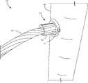
- FIG. 1is a perspective view showing an example play structure.
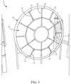
- FIG. 2is a perspective view showing an example interface.
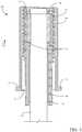
- FIG. 3is a sectional view showing an example tensioning system.
- FIG. 4is a perspective view showing example tensioning system components.
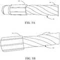
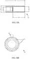
- FIGS. 5A-5Bare perspective views showing example rope configurations.
- FIG. 6is a perspective view showing an example rope coupling.
- FIG. 7is a top view showing an example tool.
- FIG. 8Ais a schematic view showing a and example tensioner schematic.
- FIG. 8Bis a schematic view showing an example tensioner schematic.
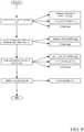
- FIG. 9is a flow diagram showing an example tensioning operation.
- FIG. 10is a perspective view showing an example tensioning system configuration.
- the deviceshould be weather and user wear resistant. Another consideration is that the device should be usable while being vandal and theft resistant. Another consideration is that the device should require minimal maintenance. To overcome variation of manufacturing tolerances related to rope lengths, it is desirable to provide a method to tension ropes when connecting to various types of playground equipment. In addition, a normal rope does experience some expansion after wearing in and may require the rope to be further tensioned to maintain a tautness in the rope.
- One example system described hereinfulfils these considerations.
- FIG. 1is a perspective view showing an example play structure 100 .
- Play structure 100includes a rope web 101 coupled to a frame 102 .
- Play structure 100can be disposed in a play environment 10 that includes other items such as other play structures.
- Rope web 101is coupled to frame 102 by tensioners 106 which couple to individual ropes 104 of rope web 101 .
- tensioner 106When installing a rope, web 101 is useful to be able to tension variably tension the ropes 104 at various connection point along frame 102 , such as tensioner 106 . In some examples, all points where rope web 101 connects to frame 102 , a tensioner 106 is used. In other examples, only some connections have tensioners 106 .
- FIG. 2is a perspective view showing an example interface 200 .
- Interface 200includes frame 202 , rope 204 and tensioning system 206 .
- Tensioning system 206includes a tensioner 208 and a collar 210 .
- Collar 210is coupled to frame 202 and, as shown, collar 210 does not move with respect to frame 202 .
- Tensioner 208is coupled to rope 204 and applies tension to rope 204 when actuated.
- Tensioner 208can be tensioned by rotating tensioner 208 which engages a threaded connection between tensioner 208 and collar 210 .
- the rotational movement of tensioner 208translates into linear movement of tensioner 208 towards (or away from) frame 202 . Since tensioner 208 is coupled to rope 204 movement of tensioner 208 causes an increase or decrease in tension of rope 204 .
- collar 210is coupled to frame 202 via a bearing, bushing or other mechanism which allows rotational movement with respect to frame 202 .
- rotational motion of collar 210will translate into motion of linear motion of tensioner 208 and also increase of decrease tension in rope 204 .
- FIG. 3is a sectional view showing an example tensioning system 306 .
- Tensioning system 306includes rope 304 , tensioner 308 , collar 310 , and structure 311 .
- Rope 304is coupled to tensioner 308 via contact of rope end 305 on ledges 312 .
- Rope end 305fits within rope end aperture 324 but cannot be pulled through tensioner 308 as it is blocked by ledges 312 . This way, when tensioner 308 moves in a direction indicated by arrow 301 , rope 304 and rope end 305 do not pull through tensioner 308 .
- Tensioner 308has a plurality of threads 316 which engage threads 314 of collar 310 . Rotation of tensioner 308 translates into linear movement between threads 314 and 316 because an engagement.
- tensioner 308includes tool engaging features 318 .
- Tool engaging features 318are configured to couple to a specific tool which allows for greater leverage and torque when rotating tensioner 308 .
- aperture 322is wide enough that a tool engaging tool engaging feature 318 can countersink tensioner 308 within collar 310 (e.g., a portion of the tool can enter aperture 322 , engage features 318 when tensioner 308 is fully disposed in collar 310 ).
- Collar 310can be coupled to a frame or other support structure to secure rope 304 indirectly to that structure.
- Collar 310includes a ledge 320 which can allow for ease of coupling to a support structure.
- the ledgecan be welded to the structure.
- the ledgecan include apertures that receive securing fasteners.
- FIG. 4is a perspective view 400 showing example tensioning system components.
- tensioner 408has a plurality of tool engaging features 418 that are accessible when tensioner 408 is inserted within collar 410 .
- Tensioner 408also has a plurality of threads 416 that engage threads (which are not shown in FIG. 4 ) of collar 410 .
- FIGS. 5A-5Bare perspective views showing example rope configurations 500 and 550 , respectively.
- Rope configuration 500includes rope 504 and rope end 505 , as shown, rope end 505 is a component that is pressed, crimped or otherwise attached to rope 504 .
- Rope end 505prevents rope 504 from being pulled through a given component (e.g., tensioner 308 of FIG. 3 ).
- Rope configuration 550includes rope 554 and rope end 555 .
- rope end 555is a component press fit or otherwise attached to the very end of rope 554 .
- This rope configurationdiffers from that of FIG. 5A .
- rope end 555is completely on the end of rope 554 .
- rope end 555can be replaced by other items as well.
- rope end 555could be a knot tied in rope 554 .
- rope and 555could include an expanded or melted piece of rope 554 that is wider than the remainder of rope 554 .
- FIG. 6is a perspective view showing an example rope coupling 600 .
- Rope coupling 600includes frame 602 , rope 604 , tensioner 605 , collar 608 , and tool 610 .
- tool 610is engaging tensioner 605 .
- tensioner 605By torqueing tool 610 tensioner 605 is rotated which will translate into linear motion of tensioner 605 towards collar 608 and frame 602 .
- tensioner 605is linearly actuated it also pulls rope 604 towards frame 602 .
- rotating tool 610 in the other directionwill release tension on rope 604 , by linearly actuating tensioner 605 away from frame 602 .
- FIG. 7is a top view showing an example tool 700 .
- tool 700has a handle 702 for a user to grip and an aperture 704 for a user to hang or otherwise store tool 700 .
- Tool 700also includes a tensioner engaging end 708 including tensioner engagement elements 706 .
- Tensioner engaging end 708includes a semi-circle of tensioner engagement elements 706 . A semi-circle allows tool 700 to be removed from the item that it is tensioning.
- tensioner engagement elements 706extrude away from a surface of the tool. In this example, tensioner engagement elements 706 can countersink a tensioner into a collar.
- FIG. 8Ais a schematic view showing a and example tensioner 800 .
- Tensioner 800has a length 802 . In one example, length 802 is approximately 4 inches.
- Tensioner 800has a diameter 804 . In one example, diameter 804 is approximately 1.4 inches.
- Tensioner 800has a threaded section having a length 806 . In one example, length 806 is approximately 2.5 inches.
- Tensioner 800has a rope receiving aperture diameter 808 . In one example diameter 808 is approximately 0.84 inches.
- Tensioner 800has a rope end receiving aperture having a diameter 810 . In one example, diameter 810 is approximately 1 inch.
- FIG. 8Bis a schematic view showing an example tensioner schematic 850 .
- Tensioner 850includes a plurality of tool engaging elements 852 .
- Tool engaging elements 852are formed as recesses defined by semi-circles 854 .
- semi-circles 854have a diameter of approximately 1 ⁇ 4 inch to 5/16 inches.
- FIG. 9is a flow diagram showing an example tensioning operation 900 .
- Operation 900begins at block 910 where the rope is coupled to a tensioner.
- Coupling the rope tensionercan include threading the rope through an aperture of tensioner, as indicated by block 912 .
- Coupling the rope to tensionercan include attaching a rope end to the rope, as indicated by block 914 . For example, by tying a knot in the rope or crimping a mechanism on the rope. Attaching a rope end to the rope will prevent the rope from pulling through a tensioner when the tensioner is linearly actuated.
- Coupling the rope to the tensionercan include other items as well, as indicated by block 916 .
- Operation 900proceeds at block 920 , where the tensioner threads are mated with the collar threads. Mating these threads can include in initial engagement between the threads such that rotation of one of the items will cause linear displacement between the two items.
- Operation 900proceeds at block 930 where the tensioner is linearly actuated relative to the collar.
- This linear actuationcan be completed by actuating the tensioner, as indicated by block 932 .
- actuating the tensionercan include engaging a tool on the tensioner and rotating the tensioner.
- Linear actuationcan be completed by actuating the collar, as indicated by the block 934 .
- the collarmay allow for rotational actuation but not linear actuation such that rotation of the collar will cause linear movement of the tensioner and minimal to no linear movement of the collar.
- Linear actuation of the tensionercan be completed in other ways as well, as indicated by block 936 .
- Operation 900proceeds at block 940 where the tensioner can optionally be loosened to reduce tension.
- Loosening tension on the ropecan be completed in similar ways as tightening. For example, loosening may also require rotational actuation, but in the opposite direction of the rotational actuation used when tightening the rope. Loosening can be accomplished in other ways as well, as indicated by block 944 .
- FIG. 10is a perspective view showing an example tensioning system configuration 1000 .
- Configuration 1000includes tensioner 1008 and collar 1010 .
- Tensioner 1008couples to collar 1010 in a threaded connection.
- tensioner 1008has tool engaging elements 1016 .
- Tool engaging elements 1016can also be used to lock tensioner 1008 in rotational alignment with collar 1010 .
- collar 1010has an aperture 1014 that receives a set screw 1012 that can engage the tool engaging elements 1016 .
- Set screw 1012is one example of a locking mechanism and other locking mechanisms may also be utilized.
Landscapes
- Engineering & Computer Science (AREA)
- General Engineering & Computer Science (AREA)
- Mechanical Engineering (AREA)
- Health & Medical Sciences (AREA)
- General Health & Medical Sciences (AREA)
- Physical Education & Sports Medicine (AREA)
- Emergency Lowering Means (AREA)
Abstract
Description
Claims (17)
Priority Applications (1)
| Application Number | Priority Date | Filing Date | Title |
|---|---|---|---|
| US16/409,221US11028901B2 (en) | 2018-05-10 | 2019-05-10 | Rope tensioning system |
Applications Claiming Priority (2)
| Application Number | Priority Date | Filing Date | Title |
|---|---|---|---|
| US201862669469P | 2018-05-10 | 2018-05-10 | |
| US16/409,221US11028901B2 (en) | 2018-05-10 | 2019-05-10 | Rope tensioning system |
Publications (2)
| Publication Number | Publication Date |
|---|---|
| US20190346019A1 US20190346019A1 (en) | 2019-11-14 |
| US11028901B2true US11028901B2 (en) | 2021-06-08 |
Family
ID=68464505
Family Applications (1)
| Application Number | Title | Priority Date | Filing Date |
|---|---|---|---|
| US16/409,221Active2039-10-23US11028901B2 (en) | 2018-05-10 | 2019-05-10 | Rope tensioning system |
Country Status (1)
| Country | Link |
|---|---|
| US (1) | US11028901B2 (en) |
Cited By (1)
| Publication number | Priority date | Publication date | Assignee | Title |
|---|---|---|---|---|
| WO2024155548A1 (en)* | 2023-01-16 | 2024-07-25 | Landscape Structures Inc. | Connector for commercial playground equipment |
Families Citing this family (4)
| Publication number | Priority date | Publication date | Assignee | Title |
|---|---|---|---|---|
| US11391345B2 (en)* | 2020-04-20 | 2022-07-19 | Landscape Structures Inc. | Cable tensioning device |
| EP4211364B1 (en) | 2020-09-14 | 2024-07-31 | Kompan A/S | A connector assembly for connecting a rope to a tubular frame |
| KR102547697B1 (en)* | 2022-09-08 | 2023-06-26 | 어드벤처 주식회사 | Installation structure of mesh net movable tunnel of tower ride |
| AU2024204303B2 (en)* | 2023-04-01 | 2025-08-14 | Systems IP Pty Ltd | A stable playground apparatus |
Citations (10)
| Publication number | Priority date | Publication date | Assignee | Title |
|---|---|---|---|---|
| US2089857A (en)* | 1936-06-13 | 1937-08-10 | American Steel & Wire Co | Clamp for securing cables |
| US3100924A (en)* | 1961-01-19 | 1963-08-20 | Union Metal Mfg Co | Wire rope fittings |
| US3346284A (en)* | 1965-03-30 | 1967-10-10 | Petersen Anita E | Swivel cable pulling grip and filler |
| US4509233A (en)* | 1983-06-15 | 1985-04-09 | Esmet, Inc. | Rope clamp construction |
| US4601506A (en)* | 1985-04-26 | 1986-07-22 | Hillson Murray G | Cable coupler for tree skidding cables |
| US5325868A (en)* | 1993-05-04 | 1994-07-05 | Kimmelstiel Carey D | Self-gripping medical wire torquer |
| US6626610B1 (en)* | 2002-04-02 | 2003-09-30 | Ben L. Seegmiller | Cable bolt apparatus and method of installation for mines |
| US20140138596A1 (en)* | 2012-11-17 | 2014-05-22 | George H. Ross | Cable railing |
| US20180003202A1 (en)* | 2016-06-29 | 2018-01-04 | Keuka Studios, Inc. | Swagless turnbuckle assembly |
| US20180340591A1 (en)* | 2015-09-11 | 2018-11-29 | Berliner Seilfabrik Gmbh & Co. | Connector |
- 2019
- 2019-05-10USUS16/409,221patent/US11028901B2/enactiveActive
Patent Citations (10)
| Publication number | Priority date | Publication date | Assignee | Title |
|---|---|---|---|---|
| US2089857A (en)* | 1936-06-13 | 1937-08-10 | American Steel & Wire Co | Clamp for securing cables |
| US3100924A (en)* | 1961-01-19 | 1963-08-20 | Union Metal Mfg Co | Wire rope fittings |
| US3346284A (en)* | 1965-03-30 | 1967-10-10 | Petersen Anita E | Swivel cable pulling grip and filler |
| US4509233A (en)* | 1983-06-15 | 1985-04-09 | Esmet, Inc. | Rope clamp construction |
| US4601506A (en)* | 1985-04-26 | 1986-07-22 | Hillson Murray G | Cable coupler for tree skidding cables |
| US5325868A (en)* | 1993-05-04 | 1994-07-05 | Kimmelstiel Carey D | Self-gripping medical wire torquer |
| US6626610B1 (en)* | 2002-04-02 | 2003-09-30 | Ben L. Seegmiller | Cable bolt apparatus and method of installation for mines |
| US20140138596A1 (en)* | 2012-11-17 | 2014-05-22 | George H. Ross | Cable railing |
| US20180340591A1 (en)* | 2015-09-11 | 2018-11-29 | Berliner Seilfabrik Gmbh & Co. | Connector |
| US20180003202A1 (en)* | 2016-06-29 | 2018-01-04 | Keuka Studios, Inc. | Swagless turnbuckle assembly |
Cited By (1)
| Publication number | Priority date | Publication date | Assignee | Title |
|---|---|---|---|---|
| WO2024155548A1 (en)* | 2023-01-16 | 2024-07-25 | Landscape Structures Inc. | Connector for commercial playground equipment |
Also Published As
| Publication number | Publication date |
|---|---|
| US20190346019A1 (en) | 2019-11-14 |
Similar Documents
| Publication | Publication Date | Title |
|---|---|---|
| US11028901B2 (en) | Rope tensioning system | |
| US9086118B2 (en) | Locking pin with spring retention mechanism | |
| EP3574794B1 (en) | Shoelace folding and releasing device | |
| DE602004007580T2 (en) | Actuator for a bicycle transmission | |
| CN102705343B (en) | With the bolt of rotation preventing mechanism | |
| US20080005876A1 (en) | Snap lock carabiner | |
| DE1954414C3 (en) | Impact expansion anchor | |
| US11885137B1 (en) | Cable system for attaching cables between two structures | |
| WO2008083337A3 (en) | Self-locking wire lock | |
| EP1577569A1 (en) | Washer and fastener provided with a washer | |
| EP0385057A1 (en) | Antiskid chain | |
| WO1996005439A1 (en) | A gripping device | |
| PL1626187T3 (en) | Shearable screw, related system and process for driving the shearable screw | |
| US20200261772A1 (en) | Carabiner retrieval devices, carabiners, and methods of use | |
| DE102007045170A1 (en) | Clamping lock for a clamping device | |
| DE102006039743A1 (en) | Clamping device for a traction means, in particular a belt or a chain | |
| EP2329747B1 (en) | Tension device for curtain rope | |
| US20100229698A1 (en) | Wire pulling and tensioning tool | |
| US9714674B1 (en) | Fastener device | |
| JP2005090530A (en) | Locking fastening structure for piling member | |
| WO2013180145A1 (en) | Tensioner | |
| EP2390429B1 (en) | Fixing device, in particular for sanitary objects fixed to the wall | |
| US20060102807A1 (en) | Cable bracket for a bicycle | |
| JP2008297709A (en) | shutter | |
| DE102004028585B4 (en) | Fastener for attaching a container to a vehicle |
Legal Events
| Date | Code | Title | Description |
|---|---|---|---|
| FEPP | Fee payment procedure | Free format text:ENTITY STATUS SET TO UNDISCOUNTED (ORIGINAL EVENT CODE: BIG.); ENTITY STATUS OF PATENT OWNER: SMALL ENTITY | |
| AS | Assignment | Owner name:LANDSCAPE STRUCTURES INC., MINNESOTA Free format text:ASSIGNMENT OF ASSIGNORS INTEREST;ASSIGNORS:JONES, BRYANT A.;NELSON, AARON;SIGNING DATES FROM 20190509 TO 20190510;REEL/FRAME:049219/0432 | |
| FEPP | Fee payment procedure | Free format text:ENTITY STATUS SET TO SMALL (ORIGINAL EVENT CODE: SMAL); ENTITY STATUS OF PATENT OWNER: SMALL ENTITY | |
| STPP | Information on status: patent application and granting procedure in general | Free format text:NON FINAL ACTION MAILED | |
| STPP | Information on status: patent application and granting procedure in general | Free format text:RESPONSE TO NON-FINAL OFFICE ACTION ENTERED AND FORWARDED TO EXAMINER | |
| STPP | Information on status: patent application and granting procedure in general | Free format text:NOTICE OF ALLOWANCE MAILED -- APPLICATION RECEIVED IN OFFICE OF PUBLICATIONS | |
| STPP | Information on status: patent application and granting procedure in general | Free format text:PUBLICATIONS -- ISSUE FEE PAYMENT RECEIVED | |
| STPP | Information on status: patent application and granting procedure in general | Free format text:PUBLICATIONS -- ISSUE FEE PAYMENT VERIFIED | |
| STCF | Information on status: patent grant | Free format text:PATENTED CASE | |
| FEPP | Fee payment procedure | Free format text:ENTITY STATUS SET TO UNDISCOUNTED (ORIGINAL EVENT CODE: BIG.); ENTITY STATUS OF PATENT OWNER: LARGE ENTITY | |
| MAFP | Maintenance fee payment | Free format text:PAYMENT OF MAINTENANCE FEE, 4TH YEAR, LARGE ENTITY (ORIGINAL EVENT CODE: M1551); ENTITY STATUS OF PATENT OWNER: LARGE ENTITY Year of fee payment:4 |