US11028756B2 - Thermal system with rankine circuit - Google Patents
Thermal system with rankine circuitDownload PDFInfo
- Publication number
- US11028756B2 US11028756B2US16/535,531US201916535531AUS11028756B2US 11028756 B2US11028756 B2US 11028756B2US 201916535531 AUS201916535531 AUS 201916535531AUS 11028756 B2US11028756 B2US 11028756B2
- Authority
- US
- United States
- Prior art keywords
- rankine
- circuit
- chamber
- pressure regulating
- regulating device
- Prior art date
- Legal status (The legal status is an assumption and is not a legal conclusion. Google has not performed a legal analysis and makes no representation as to the accuracy of the status listed.)
- Expired - Fee Related, expires
Links
Images


Classifications
- F—MECHANICAL ENGINEERING; LIGHTING; HEATING; WEAPONS; BLASTING
- F01—MACHINES OR ENGINES IN GENERAL; ENGINE PLANTS IN GENERAL; STEAM ENGINES
- F01K—STEAM ENGINE PLANTS; STEAM ACCUMULATORS; ENGINE PLANTS NOT OTHERWISE PROVIDED FOR; ENGINES USING SPECIAL WORKING FLUIDS OR CYCLES
- F01K9/00—Plants characterised by condensers arranged or modified to co-operate with the engines
- F01K9/003—Plants characterised by condensers arranged or modified to co-operate with the engines condenser cooling circuits
- F—MECHANICAL ENGINEERING; LIGHTING; HEATING; WEAPONS; BLASTING
- F01—MACHINES OR ENGINES IN GENERAL; ENGINE PLANTS IN GENERAL; STEAM ENGINES
- F01K—STEAM ENGINE PLANTS; STEAM ACCUMULATORS; ENGINE PLANTS NOT OTHERWISE PROVIDED FOR; ENGINES USING SPECIAL WORKING FLUIDS OR CYCLES
- F01K23/00—Plants characterised by more than one engine delivering power external to the plant, the engines being driven by different fluids
- F01K23/02—Plants characterised by more than one engine delivering power external to the plant, the engines being driven by different fluids the engine cycles being thermally coupled
- F01K23/06—Plants characterised by more than one engine delivering power external to the plant, the engines being driven by different fluids the engine cycles being thermally coupled combustion heat from one cycle heating the fluid in another cycle
- F01K23/10—Plants characterised by more than one engine delivering power external to the plant, the engines being driven by different fluids the engine cycles being thermally coupled combustion heat from one cycle heating the fluid in another cycle with exhaust fluid of one cycle heating the fluid in another cycle
- F—MECHANICAL ENGINEERING; LIGHTING; HEATING; WEAPONS; BLASTING
- F01—MACHINES OR ENGINES IN GENERAL; ENGINE PLANTS IN GENERAL; STEAM ENGINES
- F01D—NON-POSITIVE DISPLACEMENT MACHINES OR ENGINES, e.g. STEAM TURBINES
- F01D17/00—Regulating or controlling by varying flow
- F01D17/10—Final actuators
- F01D17/12—Final actuators arranged in stator parts
- F01D17/14—Final actuators arranged in stator parts varying effective cross-sectional area of nozzles or guide conduits
- F01D17/141—Final actuators arranged in stator parts varying effective cross-sectional area of nozzles or guide conduits by means of shiftable members or valves obturating part of the flow path
- F01D17/145—Final actuators arranged in stator parts varying effective cross-sectional area of nozzles or guide conduits by means of shiftable members or valves obturating part of the flow path by means of valves, e.g. for steam turbines
- F—MECHANICAL ENGINEERING; LIGHTING; HEATING; WEAPONS; BLASTING
- F01—MACHINES OR ENGINES IN GENERAL; ENGINE PLANTS IN GENERAL; STEAM ENGINES
- F01K—STEAM ENGINE PLANTS; STEAM ACCUMULATORS; ENGINE PLANTS NOT OTHERWISE PROVIDED FOR; ENGINES USING SPECIAL WORKING FLUIDS OR CYCLES
- F01K13/00—General layout or general methods of operation of complete plants
- F01K13/02—Controlling, e.g. stopping or starting
- F—MECHANICAL ENGINEERING; LIGHTING; HEATING; WEAPONS; BLASTING
- F01—MACHINES OR ENGINES IN GENERAL; ENGINE PLANTS IN GENERAL; STEAM ENGINES
- F01N—GAS-FLOW SILENCERS OR EXHAUST APPARATUS FOR MACHINES OR ENGINES IN GENERAL; GAS-FLOW SILENCERS OR EXHAUST APPARATUS FOR INTERNAL-COMBUSTION ENGINES
- F01N5/00—Exhaust or silencing apparatus combined or associated with devices profiting by exhaust energy
- F01N5/02—Exhaust or silencing apparatus combined or associated with devices profiting by exhaust energy the devices using heat
- F—MECHANICAL ENGINEERING; LIGHTING; HEATING; WEAPONS; BLASTING
- F02—COMBUSTION ENGINES; HOT-GAS OR COMBUSTION-PRODUCT ENGINE PLANTS
- F02G—HOT GAS OR COMBUSTION-PRODUCT POSITIVE-DISPLACEMENT ENGINE PLANTS; USE OF WASTE HEAT OF COMBUSTION ENGINES; NOT OTHERWISE PROVIDED FOR
- F02G5/00—Profiting from waste heat of combustion engines, not otherwise provided for
- F02G5/02—Profiting from waste heat of exhaust gases
- F—MECHANICAL ENGINEERING; LIGHTING; HEATING; WEAPONS; BLASTING
- F16—ENGINEERING ELEMENTS AND UNITS; GENERAL MEASURES FOR PRODUCING AND MAINTAINING EFFECTIVE FUNCTIONING OF MACHINES OR INSTALLATIONS; THERMAL INSULATION IN GENERAL
- F16K—VALVES; TAPS; COCKS; ACTUATING-FLOATS; DEVICES FOR VENTING OR AERATING
- F16K11/00—Multiple-way valves, e.g. mixing valves; Pipe fittings incorporating such valves
- F16K11/10—Multiple-way valves, e.g. mixing valves; Pipe fittings incorporating such valves with two or more closure members not moving as a unit
- F16K11/105—Three-way check or safety valves with two or more closure members
- F—MECHANICAL ENGINEERING; LIGHTING; HEATING; WEAPONS; BLASTING
- F01—MACHINES OR ENGINES IN GENERAL; ENGINE PLANTS IN GENERAL; STEAM ENGINES
- F01K—STEAM ENGINE PLANTS; STEAM ACCUMULATORS; ENGINE PLANTS NOT OTHERWISE PROVIDED FOR; ENGINES USING SPECIAL WORKING FLUIDS OR CYCLES
- F01K1/00—Steam accumulators
- F01K1/16—Other safety or control means
- F—MECHANICAL ENGINEERING; LIGHTING; HEATING; WEAPONS; BLASTING
- F01—MACHINES OR ENGINES IN GENERAL; ENGINE PLANTS IN GENERAL; STEAM ENGINES
- F01P—COOLING OF MACHINES OR ENGINES IN GENERAL; COOLING OF INTERNAL-COMBUSTION ENGINES
- F01P7/00—Controlling of coolant flow
- F01P7/14—Controlling of coolant flow the coolant being liquid
- F01P2007/146—Controlling of coolant flow the coolant being liquid using valves
- F—MECHANICAL ENGINEERING; LIGHTING; HEATING; WEAPONS; BLASTING
- F24—HEATING; RANGES; VENTILATING
- F24F—AIR-CONDITIONING; AIR-HUMIDIFICATION; VENTILATION; USE OF AIR CURRENTS FOR SCREENING
- F24F11/00—Control or safety arrangements
- F24F11/70—Control systems characterised by their outputs; Constructional details thereof
- F24F11/72—Control systems characterised by their outputs; Constructional details thereof for controlling the supply of treated air, e.g. its pressure
Definitions
- the present inventionrelates to a thermal system, in particular for a motor vehicle.
- Standard internal combustion engineshave a low performance. Indeed, only 20 to 30% of the energy from the fuel is converted into mechanical energy, while the rest is dissipated into the environment in the form of heat energy, this energy loss being dissipated in the exhaust gases and in a cooling device of the vehicle.
- a thermal systemalready exists in the state of the art comprising a Rankine cycle heat recovery device including a Rankine circuit, in which a working fluid (called Rankine fluid) circulates, the circuit including a first heat exchanger in which the Rankine fluid recovers heat from a heat source, an expander, a condenser, and a first pump.
- Rankine fluidworking fluid
- the circuitincluding a first heat exchanger in which the Rankine fluid recovers heat from a heat source, an expander, a condenser, and a first pump.
- Such a heat recovery device with Rankine cyclemakes it possible to convert the heat energy into mechanical or electrical energy.
- the first pumpmakes it possible to compress and circulate the Rankine fluid.
- This Rankine fluidenters the first heat exchanger, in which the heat from the exhaust gases or the cooling device is used to evaporate the Rankine fluid.
- This high-pressure vaporpasses through an expander, where it is expanded into low-pressure vapor.
- This expandercan be a volumetric expander, such as a piston or a spiral, or a dynamic expander, like a turbine. This expander produces mechanical energy and this mechanical energy can be converted into electricity using an electrical generator.
- the low-pressure vaporis next cooled and condensed in the condenser.
- Rankine fluidcan be subject to pressure variations between the expander and the pump, which may in some cases cause cavitation of the pump.
- a thermal systemis provided in which the pressure between the expander and the pump of the Rankine cycle heat recovery device is regulated automatically, without requiring a regulating valve.
- a thermal systemin particular for a motor vehicle, of the type including:
- the pressure regulating deviceis an additional device, therefore separate from the expander of the Rankine circuit and separate from the second pump.
- the pressure in the cooling deviceis used to control the pressure between the expander and the pump of the Rankine cycle heat recovery device.
- a thermal systemcan further include one or several of the following features, considered alone or according to all technically possible combinations:
- the inventionalso relates to an exhaust line, in particular of a motor vehicle, comprising a thermal system as previously described.
- the inventionalso relates to a vehicle, in particular a motor vehicle, comprising an exhaust line as previously described.
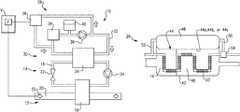
- FIG. 1is a schematic view of a thermal system according to a first exemplary embodiment of the invention
- FIG. 2is a schematic view of a pressure regulating device equipping the thermal system of FIG. 1 ;
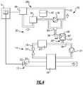
- FIG. 3is a schematic view of a thermal system according to a second exemplary embodiment of the invention.
- FIG. 4is a schematic view of a thermal system according to a third exemplary embodiment of the invention.
- FIG. 1shows a thermal system 10 , in particular intended to equip a motor vehicle V.
- the thermal system 10comprises a Rankine cycle heat recovery device 12 including a Rankine circuit 14 , in which a Rankine fluid 16 circulates, the Rankine circuit 14 including a first heat exchanger 18 in which the Rankine fluid 16 recovers heat from a heat source 20 , an expander 22 , a condenser 23 and a first pump 24 .
- the heat source 20is an exhaust gas EG.
- the condenser 23is included in a device 26 for regulating the pressure, shown in detail in FIG. 2 .
- This device 26 for regulating the pressureis arranged downstream from the expander 22 and upstream from the first pump 24 , in other words in a low-pressure part of the Rankine circuit 14 .
- the thermal system 10also comprises a cooling device 28 including a cooling circuit 30 , in which a refrigerant 32 circulates.
- the cooling circuit 30includes a second heat exchanger 34 in which the refrigerant 32 gives heat to a cold source, a second pump 36 , and a third heat exchanger 38 with a device to be cooled, the device to be cooled, for example, being an engine E of the motor vehicle V.
- the cooling circuit 30also conventionally includes an expansion tank 40 .
- the expansion tank 40meets the following operating conditions:
- the Rankine fluid 16is ethanol.
- the thermal system 10comprises the device 26 for regulating the pressure in the Rankine circuit 14 , shown in more detail in FIG. 2 .
- the pressure regulating device 26includes an enclosure 42 delimiting a space, and housing a movable part 44 separating the space into first 46 and second 48 chambers.
- the first chamber 46communicates with the Rankine circuit 14 , and it is therefore filled with Rankine fluid 16
- the second chamber 48communicates with the cooling circuit 30 , and it is therefore filled with refrigerant 32 .
- the first chamber 46houses the condenser 23 , which is formed by a heat exchange pipe, preferably provided with fins, and in which the refrigerant 32 circulates.
- the pressureis transmitted to the Rankine fluid 16 by the movable part 44 that separates the Rankine fluid 16 from the refrigerant 32 .
- the movable part 44can be formed by a membrane 44 a , a bladder 44 b , or in a variant by a piston 44 c as shown in FIG. 2 .
- the pressure in the pressure regulating device 26is the same as that in the expansion tank 40 of the cooling circuit 30 . This pressure depends on the thermal expansion of the refrigerant 32 , therefore its temperature.
- the saturation pressure upstream from the first pump 24is lower than the pressure in the expansion tank 40 .
- the pressure regulating device 26comprises an inlet pipe 50 for refrigerant 32 and an outlet pipe 52 for refrigerant 32 , connected to the cooling circuit 30 and emerging on either side of the second chamber 48 .
- the refrigerant 32can circulate in the second chamber 48 , which prevents overheating of this refrigerant 32 due to its proximity with the Rankine fluid 16 in the pressure regulating device 26 .
- the inlet pipe 50is connected to the cooling circuit 30 via a valve 54 , making it possible to control the flow rate of refrigerant 32 through the second chamber 48 .
- the valve 54is, for example, a three-way valve comprising a first path connected to the cooling circuit 30 , a second path connected to the second chamber 48 and more specifically to the refrigerant 32 inlet pipe 50 into the second chamber 48 , and a third path connected to the heat exchange pipe of the condenser 23 .
- the valve 54also makes it possible to control the flow of refrigerant 32 through the condenser 23 , in order to control the temperature of the Rankine fluid 16 leaving this condenser 23 , therefore at the inlet of the first pump 24 .
- the Rankine fluid 16takes heat in the first exchanger 18 , then is expanded in the expander 22 , before arriving in gaseous form in the first chamber 46 , where it is condensed in liquid form before leaving the first chamber 46 toward the first pump 24 .
- the refrigerant 32driven by the second pump 36 , recovers calories from the third heat exchanger 38 , to restore them to the second heat exchanger 34 , conventionally.
- Part of the refrigerant 32is, however, deflected toward the pressure regulating device 26 , and more specifically toward the condenser 23 and toward the second chamber 48 .
- the flow rate of this refrigerant portion 32is regulated by the valve 54 .
- the pressure of the refrigerant 32is transmitted to the Rankine fluid 16 by the movable part 44 , thus compensating the volume variations of the Rankine fluid 16 .
- the refrigerant 32 leaving the pressure regulating device 26next enters the second heat exchanger 34 , where it is cooled.
- FIG. 3shows a thermal system 10 according to a second exemplary embodiment of the invention.
- the elements similar to those of the two preceding figuresare designated using identical references, and will not be described again.
- the thermal system 10 according to this second embodimentdiffers from that of the first embodiment in that the condenser 23 ′ and the pressure regulating device 26 ′ are separate.
- the condenser 23 ′is then arranged downstream from the expander 22 and upstream from the pressure regulating device 26 ′.
- the pressure regulating device 26 ′includes an enclosure 42 ′ delimiting a space, and housing a movable part 44 ′ separating the space into first 46 ′ and second 48 ′ chambers.
- the movable part 44 ′is, for example, a membrane, a piston or a bladder.
- the first chamber 46 ′communicates with the Rankine circuit 14 , and more specifically with a first branch 56 connecting the condenser 23 ′ to the first pump 24 .
- the second chamber 48 ′communicates with the cooling circuit 30 , and more specifically with a second branch 58 connecting the second heat exchanger 34 to the second pump 36 .
- the operation of the pressure regulation in the Rankine circuit 14is similar to that previously described for the first embodiment.
- FIG. 4shows a thermal system 10 according to a third exemplary embodiment of the invention.
- the elements similar to those of the two preceding figuresare designated using identical references, and will not be described again.
- the thermal system 10 according to this third embodimentdiffers from that of the second embodiment in that the second chamber 48 ′ is connected to the cooling circuit 30 via a valve 60 .
- valve 60is a three-way valve arranged in parallel with the second pump 36 , including a first channel connected to the second chamber 48 ′, a second channel connected upstream from the second pump 36 , and a third channel connected downstream from the second pump 36 .
- the operation of the pressure regulation in the Rankine circuit 14is similar to that previously described for the second embodiment, with the exception of the fact that, owing to the valve 60 , the second chamber 48 ′ can be connected to the cooling circuit 30 upstream or downstream from the second pump 36 , depending on the desired pressure.
Landscapes
- Engineering & Computer Science (AREA)
- General Engineering & Computer Science (AREA)
- Mechanical Engineering (AREA)
- Chemical & Material Sciences (AREA)
- Combustion & Propulsion (AREA)
- Engine Equipment That Uses Special Cycles (AREA)
Abstract
Description
- a Rankine cycle heat recovery device including a Rankine circuit, in which a Rankine fluid circulates, the Rankine circuit including a first heat exchanger in which the Rankine fluid recovers heat from a heat source, an expander, a condenser, and a first pump,
- a cooling device including a cooling circuit in which a refrigerant circulates, the cooling circuit including a second heat exchanger in which the refrigerant gives heat to a cold source, a second pump, and a third heat exchanger with a device to be cooled,
- the thermal system comprising a device for regulating the pressure in the Rankine circuit, this pressure regulating device including an enclosure delimiting a space and housing a movable part separating the space into first and second chambers, the first chamber communicating with the Rankine circuit and the second chamber communicating with the cooling circuit.
- the pressure regulating device comprises:
- an inlet for Rankine fluid in gaseous form into the first chamber and an outlet for Rankine fluid in liquid form from the first chamber,
- an inlet pipe for refrigerant in the second chamber and an outlet pipe for refrigerant from the second chamber, and
- the condenser, formed by a heat exchange pipe extending in the first chamber and in which the refrigerant circulates.
- the thermal system comprises a valve, and in particular a three-way valve, one channel of which is connected to the second chamber and another channel of which is connected to the heat exchange pipe of the condenser.
- the pressure regulating device is separate from the condenser, the first chamber of the pressure regulating device communicating with the Rankine circuit between the condenser and the first pump.
- the second chamber is connected to the cooling circuit via a valve, the valve preferably being a three-way valve arranged in parallel with the second pump, including a first channel connected to the second chamber, a second channel connected upstream from the second pump and a third channel connected downstream from the second pump.
- the movable part of the pressure regulating device is chosen from among a membrane, a piston, or a bladder.
- the device to be cooled is a heat engine, the heat source being formed by an exhaust gas coming from this heat engine.
- the cooling circuit comprises an expansion tank.
- a pressure of between 1.2 and 2.2 bars, for example between 1.3 and 2 bars, and preferably between 1.4 and 1.7 bars,
- a temperature of between 45 and 100° C., for example between 55 and 90° C., and preferably between 65 and 80° C.
Claims (12)
Applications Claiming Priority (2)
| Application Number | Priority Date | Filing Date | Title |
|---|---|---|---|
| FR1857410 | 2018-08-09 | ||
| FR1857410AFR3084913B1 (en) | 2018-08-09 | 2018-08-09 | RANKINE CIRCUIT THERMAL SYSTEM |
Publications (2)
| Publication Number | Publication Date |
|---|---|
| US20200049052A1 US20200049052A1 (en) | 2020-02-13 |
| US11028756B2true US11028756B2 (en) | 2021-06-08 |
Family
ID=63963199
Family Applications (1)
| Application Number | Title | Priority Date | Filing Date |
|---|---|---|---|
| US16/535,531Expired - Fee RelatedUS11028756B2 (en) | 2018-08-09 | 2019-08-08 | Thermal system with rankine circuit |
Country Status (4)
| Country | Link |
|---|---|
| US (1) | US11028756B2 (en) |
| KR (1) | KR102315299B1 (en) |
| DE (1) | DE102019121076A1 (en) |
| FR (1) | FR3084913B1 (en) |
Families Citing this family (1)
| Publication number | Priority date | Publication date | Assignee | Title |
|---|---|---|---|---|
| CN114225059B (en)* | 2021-12-31 | 2023-09-22 | 老肯医疗科技股份有限公司 | Double-cabin pulsation vacuum pressure steam sterilizer and sterilization method |
Citations (25)
| Publication number | Priority date | Publication date | Assignee | Title |
|---|---|---|---|---|
| US4576005A (en)* | 1985-01-07 | 1986-03-18 | Force Louis W | Wellhead gas treatment and co-generation method and system |
| US4986225A (en)* | 1990-06-08 | 1991-01-22 | General Motors Corporation | Intake reservoir system for an engine having a check valve |
| US5351487A (en)* | 1992-05-26 | 1994-10-04 | Abdelmalek Fawzy T | High efficiency natural gas engine driven cooling system |
| US5688327A (en)* | 1996-02-26 | 1997-11-18 | Xerox Corporation | Chuck assembly having a controlled vent |
| US6651433B1 (en)* | 2002-09-13 | 2003-11-25 | Leslie C. George, Jr. | Brayton screw engine with brayton bottoming system |
| US20070163260A1 (en) | 2006-01-10 | 2007-07-19 | Steve Hargreaves | Method for converting thermal energy into mechanical work |
| US20120210713A1 (en)* | 2011-01-06 | 2012-08-23 | Cummins Intellectual Property, Inc. | Rankine cycle waste heat recovery system |
| US20120227404A1 (en) | 2009-11-14 | 2012-09-13 | Orcan Energy Gmbh | Thermodynamic Machine and Method for the Operation Thereof |
| US20130067910A1 (en)* | 2011-09-21 | 2013-03-21 | Kabushiki Kaisha Toyota Jidoshokki | Waste heat recovery system |
| US20130091884A1 (en) | 2011-10-14 | 2013-04-18 | Robert A. Hunt | Heat Powered Reciprocating Piston Engine |
| US20130327041A1 (en)* | 2010-12-16 | 2013-12-12 | Daimler Ag | Waste heat utilization device and operating method |
| US8628025B2 (en)* | 2010-03-09 | 2014-01-14 | GM Global Technology Operations LLC | Vehicle waste heat recovery system and method of operation |
| US20140165562A1 (en)* | 2011-09-30 | 2014-06-19 | Nissan Motor Co., Ltd. | Engine-waste-heat utilization device |
| US8800280B2 (en)* | 2010-04-15 | 2014-08-12 | Gershon Machine Ltd. | Generator |
| US8809656B2 (en)* | 2011-04-11 | 2014-08-19 | Paul Thomas Radosevich | Acoustic drum head tuning system and method of use |
| DE102013211875A1 (en)* | 2013-06-24 | 2015-01-08 | Robert Bosch Gmbh | Waste heat recovery system for an internal combustion engine |
| US20150300210A1 (en)* | 2014-04-16 | 2015-10-22 | IFP Energies Nouvelles | Device for controlling a closed loop working on a rankine cycle and method using same |
| US20160017760A1 (en) | 2014-07-17 | 2016-01-21 | Panasonic Intellectual Property Management Co., Ltd. | Cogenerating system |
| US20160061055A1 (en)* | 2013-03-13 | 2016-03-03 | Echogen Power Systems, L.L.C. | Control system for a heat engine system utilizing supercritical working fluid |
| DE102015215063A1 (en) | 2015-08-06 | 2017-02-09 | Mahle International Gmbh | Container for a waste heat recovery cycle |
| JP2017110551A (en) | 2015-12-16 | 2017-06-22 | 日野自動車株式会社 | Waste heat recovery device |
| US20170275190A1 (en) | 2016-03-23 | 2017-09-28 | Solar Turbines Incorporated | System using heat energy to produce power and pure water |
| US9777602B2 (en)* | 2007-03-02 | 2017-10-03 | Victor Juchymenko | Supplementary thermal energy transfer in thermal energy recovery systems |
| KR101868273B1 (en) | 2017-03-28 | 2018-06-15 | 두산중공업 주식회사 | Control device for suppling of working fluid |
| US20180187573A1 (en)* | 2015-06-30 | 2018-07-05 | Rudolf Gutscher | Steam power plant |
- 2018
- 2018-08-09FRFR1857410Apatent/FR3084913B1/ennot_activeExpired - Fee Related
- 2019
- 2019-08-05DEDE102019121076.3Apatent/DE102019121076A1/ennot_activeCeased
- 2019-08-08USUS16/535,531patent/US11028756B2/ennot_activeExpired - Fee Related
- 2019-08-08KRKR1020190096848Apatent/KR102315299B1/ennot_activeExpired - Fee Related
Patent Citations (27)
| Publication number | Priority date | Publication date | Assignee | Title |
|---|---|---|---|---|
| US4576005A (en)* | 1985-01-07 | 1986-03-18 | Force Louis W | Wellhead gas treatment and co-generation method and system |
| US4986225A (en)* | 1990-06-08 | 1991-01-22 | General Motors Corporation | Intake reservoir system for an engine having a check valve |
| US5351487A (en)* | 1992-05-26 | 1994-10-04 | Abdelmalek Fawzy T | High efficiency natural gas engine driven cooling system |
| US5688327A (en)* | 1996-02-26 | 1997-11-18 | Xerox Corporation | Chuck assembly having a controlled vent |
| US6651433B1 (en)* | 2002-09-13 | 2003-11-25 | Leslie C. George, Jr. | Brayton screw engine with brayton bottoming system |
| US20070163260A1 (en) | 2006-01-10 | 2007-07-19 | Steve Hargreaves | Method for converting thermal energy into mechanical work |
| US9777602B2 (en)* | 2007-03-02 | 2017-10-03 | Victor Juchymenko | Supplementary thermal energy transfer in thermal energy recovery systems |
| US20120227404A1 (en) | 2009-11-14 | 2012-09-13 | Orcan Energy Gmbh | Thermodynamic Machine and Method for the Operation Thereof |
| US8628025B2 (en)* | 2010-03-09 | 2014-01-14 | GM Global Technology Operations LLC | Vehicle waste heat recovery system and method of operation |
| US8800280B2 (en)* | 2010-04-15 | 2014-08-12 | Gershon Machine Ltd. | Generator |
| US20130327041A1 (en)* | 2010-12-16 | 2013-12-12 | Daimler Ag | Waste heat utilization device and operating method |
| US20120210713A1 (en)* | 2011-01-06 | 2012-08-23 | Cummins Intellectual Property, Inc. | Rankine cycle waste heat recovery system |
| US8809656B2 (en)* | 2011-04-11 | 2014-08-19 | Paul Thomas Radosevich | Acoustic drum head tuning system and method of use |
| US20130067910A1 (en)* | 2011-09-21 | 2013-03-21 | Kabushiki Kaisha Toyota Jidoshokki | Waste heat recovery system |
| US20140165562A1 (en)* | 2011-09-30 | 2014-06-19 | Nissan Motor Co., Ltd. | Engine-waste-heat utilization device |
| US20130091884A1 (en) | 2011-10-14 | 2013-04-18 | Robert A. Hunt | Heat Powered Reciprocating Piston Engine |
| US20160061055A1 (en)* | 2013-03-13 | 2016-03-03 | Echogen Power Systems, L.L.C. | Control system for a heat engine system utilizing supercritical working fluid |
| DE102013211875A1 (en)* | 2013-06-24 | 2015-01-08 | Robert Bosch Gmbh | Waste heat recovery system for an internal combustion engine |
| US20150300210A1 (en)* | 2014-04-16 | 2015-10-22 | IFP Energies Nouvelles | Device for controlling a closed loop working on a rankine cycle and method using same |
| US20160017760A1 (en) | 2014-07-17 | 2016-01-21 | Panasonic Intellectual Property Management Co., Ltd. | Cogenerating system |
| JP2016029278A (en) | 2014-07-17 | 2016-03-03 | パナソニックIpマネジメント株式会社 | Cogeneration system |
| US20180187573A1 (en)* | 2015-06-30 | 2018-07-05 | Rudolf Gutscher | Steam power plant |
| DE102015215063A1 (en) | 2015-08-06 | 2017-02-09 | Mahle International Gmbh | Container for a waste heat recovery cycle |
| JP2017110551A (en) | 2015-12-16 | 2017-06-22 | 日野自動車株式会社 | Waste heat recovery device |
| US20170275190A1 (en) | 2016-03-23 | 2017-09-28 | Solar Turbines Incorporated | System using heat energy to produce power and pure water |
| KR101868273B1 (en) | 2017-03-28 | 2018-06-15 | 두산중공업 주식회사 | Control device for suppling of working fluid |
| US20180283222A1 (en) | 2017-03-28 | 2018-10-04 | Doosan Heavy Industries & Construction Co., Ltd. | Device for controlling supply of working fluid |
Non-Patent Citations (1)
| Title |
|---|
| International Search Report for French Application No. 1857410 dated Feb. 19, 2019. |
Also Published As
| Publication number | Publication date |
|---|---|
| DE102019121076A1 (en) | 2020-02-13 |
| US20200049052A1 (en) | 2020-02-13 |
| KR20200018323A (en) | 2020-02-19 |
| FR3084913A1 (en) | 2020-02-14 |
| KR102315299B1 (en) | 2021-10-19 |
| FR3084913B1 (en) | 2020-07-31 |
Similar Documents
| Publication | Publication Date | Title |
|---|---|---|
| US9752462B1 (en) | Supercritical fluid heat engine | |
| US8826663B2 (en) | Heat exchanger | |
| KR20160115744A (en) | Turbine engine with integrated heat recovery and cooling cycle system | |
| KR20020097208A (en) | An engine | |
| US20180371955A1 (en) | Cogeneration system | |
| EP3803064A1 (en) | System for recovering waste heat and method thereof | |
| CN104279542A (en) | Boiler system | |
| US11028756B2 (en) | Thermal system with rankine circuit | |
| CN109196201B (en) | Reversible system for dissipating thermal power generated in a gas turbine engine | |
| CA2107300A1 (en) | Method and apparatus for compressing a gaseous medium | |
| EP2765281B1 (en) | A rankine cycle apparatus | |
| JP2010164216A (en) | High temperature-type heat pump system | |
| US12163490B2 (en) | Turbocharged compressor | |
| CA2894503A1 (en) | Engine inlet air cooling system and method | |
| KR102310951B1 (en) | Gas supply system and gas filling device using the same | |
| CN110291347A (en) | Method for operating a heat pump installation, heat pump installation and power plant with heat pump installation | |
| JP2021162019A (en) | Intercooling reheat type gas turbine, and composite system of refrigerant composite bottoming cycle | |
| CN115298417B (en) | Multi-core heat recovery booster cooler | |
| US12421888B2 (en) | Multi-core heat recovery charge cooler | |
| US20240210072A1 (en) | Heat pump steam generator | |
| RU2029117C1 (en) | Gas-turbine engine | |
| WO2025198581A1 (en) | Heat pump steam generator | |
| WO2024240818A1 (en) | District heating plant and method | |
| Mashhadi et al. | A steam Rankine cycle with two-stage pumping to enhance the waste heat recovery from internal combustion engines | |
| KR20180012995A (en) | Heat pump device |
Legal Events
| Date | Code | Title | Description |
|---|---|---|---|
| FEPP | Fee payment procedure | Free format text:ENTITY STATUS SET TO UNDISCOUNTED (ORIGINAL EVENT CODE: BIG.); ENTITY STATUS OF PATENT OWNER: LARGE ENTITY | |
| STPP | Information on status: patent application and granting procedure in general | Free format text:DOCKETED NEW CASE - READY FOR EXAMINATION | |
| AS | Assignment | Owner name:FAURECIA SYSTEMES D'ECHAPPEMENT, FRANCE Free format text:ASSIGNMENT OF ASSIGNORS INTEREST;ASSIGNOR:RAPIOR, JULIEN;REEL/FRAME:051406/0498 Effective date:20191119 | |
| STPP | Information on status: patent application and granting procedure in general | Free format text:NON FINAL ACTION MAILED | |
| STPP | Information on status: patent application and granting procedure in general | Free format text:NOTICE OF ALLOWANCE MAILED -- APPLICATION RECEIVED IN OFFICE OF PUBLICATIONS | |
| STPP | Information on status: patent application and granting procedure in general | Free format text:PUBLICATIONS -- ISSUE FEE PAYMENT RECEIVED | |
| STPP | Information on status: patent application and granting procedure in general | Free format text:PUBLICATIONS -- ISSUE FEE PAYMENT VERIFIED | |
| STCF | Information on status: patent grant | Free format text:PATENTED CASE | |
| FEPP | Fee payment procedure | Free format text:MAINTENANCE FEE REMINDER MAILED (ORIGINAL EVENT CODE: REM.); ENTITY STATUS OF PATENT OWNER: LARGE ENTITY | |
| LAPS | Lapse for failure to pay maintenance fees | Free format text:PATENT EXPIRED FOR FAILURE TO PAY MAINTENANCE FEES (ORIGINAL EVENT CODE: EXP.); ENTITY STATUS OF PATENT OWNER: LARGE ENTITY | |
| STCH | Information on status: patent discontinuation | Free format text:PATENT EXPIRED DUE TO NONPAYMENT OF MAINTENANCE FEES UNDER 37 CFR 1.362 | |
| FP | Lapsed due to failure to pay maintenance fee | Effective date:20250608 |