US11026758B2 - Medical robotics systems implementing axis constraints during actuation of one or more motorized joints - Google Patents
Medical robotics systems implementing axis constraints during actuation of one or more motorized jointsDownload PDFInfo
- Publication number
- US11026758B2 US11026758B2US16/011,521US201816011521AUS11026758B2US 11026758 B2US11026758 B2US 11026758B2US 201816011521 AUS201816011521 AUS 201816011521AUS 11026758 B2US11026758 B2US 11026758B2
- Authority
- US
- United States
- Prior art keywords
- motorized
- joints
- axis
- joint
- robotic arm
- Prior art date
- Legal status (The legal status is an assumption and is not a legal conclusion. Google has not performed a legal analysis and makes no representation as to the accuracy of the status listed.)
- Active, expires
Links
- 238000000034methodMethods0.000claimsabstractdescription188
- 230000033001locomotionEffects0.000claimsdescription191
- 230000004044responseEffects0.000claimsdescription56
- 238000003860storageMethods0.000claimsdescription45
- 230000008878couplingEffects0.000claimsdescription30
- 238000010168coupling processMethods0.000claimsdescription30
- 238000005859coupling reactionMethods0.000claimsdescription30
- 230000015654memoryEffects0.000claimsdescription19
- 238000004891communicationMethods0.000claimsdescription9
- 230000008859changeEffects0.000claimsdescription7
- 238000003780insertionMethods0.000abstractdescription48
- 230000037431insertionEffects0.000abstractdescription48
- 239000011295pitchSubstances0.000description37
- 230000004807localizationEffects0.000description22
- 230000008569processEffects0.000description16
- 210000002435tendonAnatomy0.000description16
- 210000003484anatomyAnatomy0.000description15
- 238000002357laparoscopic surgeryMethods0.000description12
- 238000013276bronchoscopyMethods0.000description11
- 238000013461designMethods0.000description11
- 238000013519translationMethods0.000description11
- 230000008901benefitEffects0.000description10
- 238000003032molecular dockingMethods0.000description10
- 230000007704transitionEffects0.000description10
- 239000012636effectorSubstances0.000description9
- 238000001839endoscopyMethods0.000description9
- 230000003287optical effectEffects0.000description9
- 210000001015abdomenAnatomy0.000description8
- 238000005452bendingMethods0.000description8
- 230000007246mechanismEffects0.000description7
- 238000012545processingMethods0.000description7
- 238000003384imaging methodMethods0.000description6
- 230000001225therapeutic effectEffects0.000description6
- 210000003708urethraAnatomy0.000description6
- 230000009471actionEffects0.000description5
- 238000002591computed tomographyMethods0.000description5
- 238000003973irrigationMethods0.000description5
- 230000002262irrigationEffects0.000description5
- 238000013507mappingMethods0.000description5
- 239000012530fluidSubstances0.000description4
- 210000003734kidneyAnatomy0.000description4
- 210000004072lungAnatomy0.000description4
- 230000005855radiationEffects0.000description4
- 238000012546transferMethods0.000description4
- 210000000626ureterAnatomy0.000description4
- 230000002792vascularEffects0.000description4
- 210000000683abdominal cavityAnatomy0.000description3
- 230000003187abdominal effectEffects0.000description3
- 238000001574biopsyMethods0.000description3
- 210000001105femoral arteryAnatomy0.000description3
- 230000002496gastric effectEffects0.000description3
- 210000002414legAnatomy0.000description3
- 239000000463materialSubstances0.000description3
- 230000001954sterilising effectEffects0.000description3
- 238000004659sterilization and disinfectionMethods0.000description3
- 238000001356surgical procedureMethods0.000description3
- 238000011282treatmentMethods0.000description3
- 210000000707wristAnatomy0.000description3
- 210000003815abdominal wallAnatomy0.000description2
- 238000013459approachMethods0.000description2
- 230000006835compressionEffects0.000description2
- 238000007906compressionMethods0.000description2
- 238000004590computer programMethods0.000description2
- 238000010586diagramMethods0.000description2
- 238000006073displacement reactionMethods0.000description2
- 238000005516engineering processMethods0.000description2
- 239000000835fiberSubstances0.000description2
- 230000006870functionEffects0.000description2
- 238000002575gastroscopyMethods0.000description2
- 239000011521glassSubstances0.000description2
- 210000004013groinAnatomy0.000description2
- 238000002372labellingMethods0.000description2
- 230000003902lesionEffects0.000description2
- 239000013307optical fiberSubstances0.000description2
- 230000005693optoelectronicsEffects0.000description2
- 230000002085persistent effectEffects0.000description2
- 239000007787solidSubstances0.000description2
- 230000003068static effectEffects0.000description2
- 210000001835visceraAnatomy0.000description2
- 238000004804windingMethods0.000description2
- 206010073306Exposure to radiationDiseases0.000description1
- 208000000913Kidney CalculiDiseases0.000description1
- 241000699670Mus sp.Species0.000description1
- 206010029148NephrolithiasisDiseases0.000description1
- 238000012084abdominal surgeryMethods0.000description1
- 230000003213activating effectEffects0.000description1
- 239000000853adhesiveSubstances0.000description1
- 230000001070adhesive effectEffects0.000description1
- 210000001367arteryAnatomy0.000description1
- 230000000712assemblyEffects0.000description1
- 238000000429assemblyMethods0.000description1
- 239000008280bloodSubstances0.000description1
- 210000004369bloodAnatomy0.000description1
- 210000002302brachial arteryAnatomy0.000description1
- 238000004364calculation methodMethods0.000description1
- 210000001715carotid arteryAnatomy0.000description1
- 210000001072colonAnatomy0.000description1
- 238000005520cutting processMethods0.000description1
- 230000003247decreasing effectEffects0.000description1
- 238000001514detection methodMethods0.000description1
- 238000003745diagnosisMethods0.000description1
- 230000000694effectsEffects0.000description1
- 238000007667floatingMethods0.000description1
- 238000002594fluoroscopyMethods0.000description1
- 239000012634fragmentSubstances0.000description1
- 230000005484gravityEffects0.000description1
- 230000035876healingEffects0.000description1
- 230000036541healthEffects0.000description1
- 210000001624hipAnatomy0.000description1
- 238000010348incorporationMethods0.000description1
- 230000036512infertilityEffects0.000description1
- 230000003993interactionEffects0.000description1
- 230000002452interceptive effectEffects0.000description1
- 210000000936intestineAnatomy0.000description1
- 230000000670limiting effectEffects0.000description1
- 230000003211malignant effectEffects0.000description1
- 238000005259measurementMethods0.000description1
- 239000012528membraneSubstances0.000description1
- 239000000203mixtureSubstances0.000description1
- 238000012986modificationMethods0.000description1
- 230000004048modificationEffects0.000description1
- 238000012544monitoring processMethods0.000description1
- 238000011022operating instructionMethods0.000description1
- 238000005457optimizationMethods0.000description1
- 230000007170pathologyEffects0.000description1
- 238000011471prostatectomyMethods0.000description1
- 230000001012protectorEffects0.000description1
- 238000009877renderingMethods0.000description1
- 230000029058respiratory gaseous exchangeEffects0.000description1
- 230000000284resting effectEffects0.000description1
- 238000005096rolling processMethods0.000description1
- 238000000926separation methodMethods0.000description1
- 238000001228spectrumMethods0.000description1
- 230000000087stabilizing effectEffects0.000description1
- 239000004575stoneSubstances0.000description1
- 238000002560therapeutic procedureMethods0.000description1
- 238000003325tomographyMethods0.000description1
- 210000003437tracheaAnatomy0.000description1
- 230000009466transformationEffects0.000description1
- 238000009211ultrasonic lithotripsyMethods0.000description1
- 210000000689upper legAnatomy0.000description1
- 230000000007visual effectEffects0.000description1
- XLYOFNOQVPJJNP-UHFFFAOYSA-NwaterSubstancesOXLYOFNOQVPJJNP-UHFFFAOYSA-N0.000description1
- 201000009482yawsDiseases0.000description1
Images


Classifications
- A—HUMAN NECESSITIES
- A61—MEDICAL OR VETERINARY SCIENCE; HYGIENE
- A61B—DIAGNOSIS; SURGERY; IDENTIFICATION
- A61B34/00—Computer-aided surgery; Manipulators or robots specially adapted for use in surgery
- A61B34/30—Surgical robots
- A61B34/35—Surgical robots for telesurgery
- A—HUMAN NECESSITIES
- A61—MEDICAL OR VETERINARY SCIENCE; HYGIENE
- A61B—DIAGNOSIS; SURGERY; IDENTIFICATION
- A61B34/00—Computer-aided surgery; Manipulators or robots specially adapted for use in surgery
- A61B34/20—Surgical navigation systems; Devices for tracking or guiding surgical instruments, e.g. for frameless stereotaxis
- A—HUMAN NECESSITIES
- A61—MEDICAL OR VETERINARY SCIENCE; HYGIENE
- A61B—DIAGNOSIS; SURGERY; IDENTIFICATION
- A61B34/00—Computer-aided surgery; Manipulators or robots specially adapted for use in surgery
- A61B34/25—User interfaces for surgical systems
- A—HUMAN NECESSITIES
- A61—MEDICAL OR VETERINARY SCIENCE; HYGIENE
- A61B—DIAGNOSIS; SURGERY; IDENTIFICATION
- A61B34/00—Computer-aided surgery; Manipulators or robots specially adapted for use in surgery
- A61B34/30—Surgical robots
- A—HUMAN NECESSITIES
- A61—MEDICAL OR VETERINARY SCIENCE; HYGIENE
- A61B—DIAGNOSIS; SURGERY; IDENTIFICATION
- A61B34/00—Computer-aided surgery; Manipulators or robots specially adapted for use in surgery
- A61B34/70—Manipulators specially adapted for use in surgery
- A—HUMAN NECESSITIES
- A61—MEDICAL OR VETERINARY SCIENCE; HYGIENE
- A61B—DIAGNOSIS; SURGERY; IDENTIFICATION
- A61B34/00—Computer-aided surgery; Manipulators or robots specially adapted for use in surgery
- A61B34/70—Manipulators specially adapted for use in surgery
- A61B34/76—Manipulators having means for providing feel, e.g. force or tactile feedback
- A—HUMAN NECESSITIES
- A61—MEDICAL OR VETERINARY SCIENCE; HYGIENE
- A61B—DIAGNOSIS; SURGERY; IDENTIFICATION
- A61B90/00—Instruments, implements or accessories specially adapted for surgery or diagnosis and not covered by any of the groups A61B1/00 - A61B50/00, e.g. for luxation treatment or for protecting wound edges
- A61B90/50—Supports for surgical instruments, e.g. articulated arms
- A61B90/57—Accessory clamps
- A—HUMAN NECESSITIES
- A61—MEDICAL OR VETERINARY SCIENCE; HYGIENE
- A61G—TRANSPORT, PERSONAL CONVEYANCES, OR ACCOMMODATION SPECIALLY ADAPTED FOR PATIENTS OR DISABLED PERSONS; OPERATING TABLES OR CHAIRS; CHAIRS FOR DENTISTRY; FUNERAL DEVICES
- A61G13/00—Operating tables; Auxiliary appliances therefor
- A61G13/02—Adjustable operating tables; Controls therefor
- A61G13/04—Adjustable operating tables; Controls therefor tiltable around transverse or longitudinal axis
- A—HUMAN NECESSITIES
- A61—MEDICAL OR VETERINARY SCIENCE; HYGIENE
- A61G—TRANSPORT, PERSONAL CONVEYANCES, OR ACCOMMODATION SPECIALLY ADAPTED FOR PATIENTS OR DISABLED PERSONS; OPERATING TABLES OR CHAIRS; CHAIRS FOR DENTISTRY; FUNERAL DEVICES
- A61G13/00—Operating tables; Auxiliary appliances therefor
- A61G13/10—Parts, details or accessories
- B—PERFORMING OPERATIONS; TRANSPORTING
- B25—HAND TOOLS; PORTABLE POWER-DRIVEN TOOLS; MANIPULATORS
- B25J—MANIPULATORS; CHAMBERS PROVIDED WITH MANIPULATION DEVICES
- B25J9/00—Programme-controlled manipulators
- B25J9/16—Programme controls
- B25J9/1674—Programme controls characterised by safety, monitoring, diagnostic
- B25J9/1676—Avoiding collision or forbidden zones
- A—HUMAN NECESSITIES
- A61—MEDICAL OR VETERINARY SCIENCE; HYGIENE
- A61B—DIAGNOSIS; SURGERY; IDENTIFICATION
- A61B10/00—Instruments for taking body samples for diagnostic purposes; Other methods or instruments for diagnosis, e.g. for vaccination diagnosis, sex determination or ovulation-period determination; Throat striking implements
- A61B10/02—Instruments for taking cell samples or for biopsy
- A61B10/0233—Pointed or sharp biopsy instruments
- A—HUMAN NECESSITIES
- A61—MEDICAL OR VETERINARY SCIENCE; HYGIENE
- A61B—DIAGNOSIS; SURGERY; IDENTIFICATION
- A61B17/00—Surgical instruments, devices or methods
- A61B2017/00017—Electrical control of surgical instruments
- A61B2017/00115—Electrical control of surgical instruments with audible or visual output
- A—HUMAN NECESSITIES
- A61—MEDICAL OR VETERINARY SCIENCE; HYGIENE
- A61B—DIAGNOSIS; SURGERY; IDENTIFICATION
- A61B17/00—Surgical instruments, devices or methods
- A61B2017/00743—Type of operation; Specification of treatment sites
- A61B2017/00809—Lung operations
- A—HUMAN NECESSITIES
- A61—MEDICAL OR VETERINARY SCIENCE; HYGIENE
- A61B—DIAGNOSIS; SURGERY; IDENTIFICATION
- A61B34/00—Computer-aided surgery; Manipulators or robots specially adapted for use in surgery
- A61B34/10—Computer-aided planning, simulation or modelling of surgical operations
- A61B2034/101—Computer-aided simulation of surgical operations
- A61B2034/105—Modelling of the patient, e.g. for ligaments or bones
- A—HUMAN NECESSITIES
- A61—MEDICAL OR VETERINARY SCIENCE; HYGIENE
- A61B—DIAGNOSIS; SURGERY; IDENTIFICATION
- A61B34/00—Computer-aided surgery; Manipulators or robots specially adapted for use in surgery
- A61B34/20—Surgical navigation systems; Devices for tracking or guiding surgical instruments, e.g. for frameless stereotaxis
- A61B2034/2046—Tracking techniques
- A61B2034/2048—Tracking techniques using an accelerometer or inertia sensor
- A—HUMAN NECESSITIES
- A61—MEDICAL OR VETERINARY SCIENCE; HYGIENE
- A61B—DIAGNOSIS; SURGERY; IDENTIFICATION
- A61B34/00—Computer-aided surgery; Manipulators or robots specially adapted for use in surgery
- A61B34/20—Surgical navigation systems; Devices for tracking or guiding surgical instruments, e.g. for frameless stereotaxis
- A61B2034/2046—Tracking techniques
- A61B2034/2051—Electromagnetic tracking systems
- A—HUMAN NECESSITIES
- A61—MEDICAL OR VETERINARY SCIENCE; HYGIENE
- A61B—DIAGNOSIS; SURGERY; IDENTIFICATION
- A61B34/00—Computer-aided surgery; Manipulators or robots specially adapted for use in surgery
- A61B34/20—Surgical navigation systems; Devices for tracking or guiding surgical instruments, e.g. for frameless stereotaxis
- A61B2034/2046—Tracking techniques
- A61B2034/2059—Mechanical position encoders
- A—HUMAN NECESSITIES
- A61—MEDICAL OR VETERINARY SCIENCE; HYGIENE
- A61B—DIAGNOSIS; SURGERY; IDENTIFICATION
- A61B34/00—Computer-aided surgery; Manipulators or robots specially adapted for use in surgery
- A61B34/20—Surgical navigation systems; Devices for tracking or guiding surgical instruments, e.g. for frameless stereotaxis
- A61B2034/2046—Tracking techniques
- A61B2034/2065—Tracking using image or pattern recognition
- A—HUMAN NECESSITIES
- A61—MEDICAL OR VETERINARY SCIENCE; HYGIENE
- A61B—DIAGNOSIS; SURGERY; IDENTIFICATION
- A61B34/00—Computer-aided surgery; Manipulators or robots specially adapted for use in surgery
- A61B34/30—Surgical robots
- A61B2034/305—Details of wrist mechanisms at distal ends of robotic arms
- A—HUMAN NECESSITIES
- A61—MEDICAL OR VETERINARY SCIENCE; HYGIENE
- A61B—DIAGNOSIS; SURGERY; IDENTIFICATION
- A61B90/00—Instruments, implements or accessories specially adapted for surgery or diagnosis and not covered by any of the groups A61B1/00 - A61B50/00, e.g. for luxation treatment or for protecting wound edges
- A61B90/30—Devices for illuminating a surgical field, the devices having an interrelation with other surgical devices or with a surgical procedure
- A61B2090/306—Devices for illuminating a surgical field, the devices having an interrelation with other surgical devices or with a surgical procedure using optical fibres
- A—HUMAN NECESSITIES
- A61—MEDICAL OR VETERINARY SCIENCE; HYGIENE
- A61B—DIAGNOSIS; SURGERY; IDENTIFICATION
- A61B90/00—Instruments, implements or accessories specially adapted for surgery or diagnosis and not covered by any of the groups A61B1/00 - A61B50/00, e.g. for luxation treatment or for protecting wound edges
- A61B90/36—Image-producing devices or illumination devices not otherwise provided for
- A61B90/361—Image-producing devices, e.g. surgical cameras
- A61B2090/3614—Image-producing devices, e.g. surgical cameras using optical fibre
- A—HUMAN NECESSITIES
- A61—MEDICAL OR VETERINARY SCIENCE; HYGIENE
- A61B—DIAGNOSIS; SURGERY; IDENTIFICATION
- A61B90/00—Instruments, implements or accessories specially adapted for surgery or diagnosis and not covered by any of the groups A61B1/00 - A61B50/00, e.g. for luxation treatment or for protecting wound edges
- A61B90/36—Image-producing devices or illumination devices not otherwise provided for
- A61B90/37—Surgical systems with images on a monitor during operation
- A61B2090/376—Surgical systems with images on a monitor during operation using X-rays, e.g. fluoroscopy
- A—HUMAN NECESSITIES
- A61—MEDICAL OR VETERINARY SCIENCE; HYGIENE
- A61B—DIAGNOSIS; SURGERY; IDENTIFICATION
- A61B90/00—Instruments, implements or accessories specially adapted for surgery or diagnosis and not covered by any of the groups A61B1/00 - A61B50/00, e.g. for luxation treatment or for protecting wound edges
- A61B90/50—Supports for surgical instruments, e.g. articulated arms
- A61B2090/508—Supports for surgical instruments, e.g. articulated arms with releasable brake mechanisms
- A—HUMAN NECESSITIES
- A61—MEDICAL OR VETERINARY SCIENCE; HYGIENE
- A61B—DIAGNOSIS; SURGERY; IDENTIFICATION
- A61B90/00—Instruments, implements or accessories specially adapted for surgery or diagnosis and not covered by any of the groups A61B1/00 - A61B50/00, e.g. for luxation treatment or for protecting wound edges
- A61B90/50—Supports for surgical instruments, e.g. articulated arms
- A61B90/57—Accessory clamps
- A61B2090/571—Accessory clamps for clamping a support arm to a bed or other supports
Definitions
- the systems and methods disclosed hereinare directed to medical devices, and more particularly to robotic systems.
- Robotic systemscan assist physicians in performing medical procedures.
- Various medical proceduresinvolve localization of a three-dimensional position of a medical instrument within a patient's body in order to provide diagnosis and/or treatment.
- Articulated robotic armscan be operated under the control of a physician, partially autonomously, or completely autonomously to position the medical instrument at the correct location. Due to use of robotic systems, procedures may be performed with greater precision, smaller incisions, decreased blood loss, and quicker healing time, to name a few examples.
- a robotic armincludes a versatile kinematic chain and is controlled by computer-implemented instructions that enable the robotic arm to operate in a variety of modes, with different modes usable for different types of medical procedures.
- the kinematic chainincludes a number of motorized joints coupled by linkages in a serial fashion, for example configured as an open chain serial link manipulator.
- a first motorized joint at the proximal end of the robotic armis a revolute joint and a second motorized joint at the distal end of the robotic arm (e.g., closest to the medical instrument) is a prismatic joint, with a number of additional motorized joints positioned serially between the first and second motorized joints.
- the additional motorized jointscan be either revolute or prismatic as explained in more detail below.
- a revolute jointimparts rotary motion to a connected linkage
- a prismatic jointimparts linear motion to a connected linkage.
- each joint of the robotic armcan include its own independently actuatable motor in order to achieve the disclosed operational modes.
- a first modemay be suitable for use during a laparoscopic procedure.
- laparoscopymedical instruments are inserted through incisions in the abdominal wall to access the patient's internal organs.
- the instructions for operating the robotic system in the first modecan include identifying a remote center at or near the location of the incision, and constraining the actuation of the motorized joints to maintain intersection of at least an insertion axis with the remote center. This can mitigate or prevent undue stress to patient tissue around the incision during manipulation of the medical instrument.
- a remote centercan be considered as a fixed point around which the medical instrument rotates, with no physical revolute joint of the robotic system physically located at the remote center.
- a second modemay be suitable for use during endoscopic procedures including bronchoscopy procedures, gastroscopy procedures, and ureteroscopy procedures, to name a few.
- endoscopymedical instruments are moved along an insertion axis aligned with a natural orifice of the patient, with some steerable instruments capable of articulation while inserted into the patient's body.
- the instructions for operating the robotic system in the second modecan include identifying a virtual position of a virtual rail such that the insertion axis along the virtual rail is aligned with the orifice, and actuating at least one of the motorized joints to control movement of the medical instrument along the virtual rail.
- one aspectrelates to a robotic system configured to perform medical procedures, the system comprising a robotic arm configured to control movement of a medical instrument with respect to at least first, second, and third axes, the robotic arm comprising a plurality of linkages serially coupling a plurality of motorized joints, the plurality of motorized joints including a first motorized joint comprising a revolute joint, the first motorized joint configured to actuate the movement of the medical instrument about the first axis, a second motorized joint comprising a prismatic joint configured to linearly translate the medical instrument along the second axis, and a plurality of additional motorized joints positioned serially between the first and second motorized joints, the plurality of additional motorized joints configured to actuate the movement of the medical instrument about the third axis; at least one computer-readable memory having stored thereon executable instructions for operating the robotic system in one of a first and second operating modes; and at least one processor in communication with the at least one computer-readable memory and configured to execute the instructions to cause the system to
- each of the plurality of motorized jointscomprises its own motor. In some embodiments, each of the plurality of motorized joints further comprises a position sensor configured to determine a position of a rotor of the motor. In some embodiments, the at least one processor is configured to execute the instructions to cause the system to at least control positioning of the robotic arm in the first and second operating modes based at least partly on the position of the rotor of the motor of each of the plurality of motorized joints.
- the at least one processoris configured to execute the instructions to cause the system to at least actuate the second motorized joint to move the medical instrument along the virtual rail. In some embodiments, the at least one processor is configured to execute the instructions to cause the system to at least coordinate actuation of two or more of the plurality of motorized joints to move the medical instrument along the virtual rail.
- the plurality of additional motorized jointscomprise third, fourth, and fifth joints.
- the at least one processoris configured to execute the instructions to cause the system to at least identify a virtual orientation of a virtual linkage between the remote center and the third joint; and maintain positioning of a linkage of the plurality of linkages coupling the fourth and fifth joints parallel with the virtual orientation of the virtual linkage.
- the at least one processoris configured to execute the instructions to cause the system to at least change a distance between the remote center and the third joint.
- the at least one processoris configured to execute the instructions to cause the system to at least fix a distance between the remote center and the third joint to be equal to a length of the linkage coupling the fourth and fifth joints.
- each of the third, fourth, and fifth jointscomprises an additional revolute joint.
- a first linkage of the plurality of linkagescouples the first and third joints
- a second linkage of the plurality of linkagescouples the third and fourth joints
- a first length of the first linkageis longer than a second length of the second linkage.
- the at least one processoris configured to execute the instructions to cause the system to at least rotate the third and fourth joints such that the fourth joint passes from a first position on a first side of the first linkage past the first joint to a position on a second side of the first linkage.
- a third linkage of the plurality of linkagescouples the fourth and fifth joints, with the first, second, and third linkages being configured to be positioned in a substantially parallel fashion with the second linkage positioned between the first and third linkages.
- the at least one processoris configured to position the first, second, and third linkages in the substantially parallel fashion in response to receiving a storage command.
- a fourth linkagecouples the second and fifth joints, the fourth linkage configured to be substantially parallel with and adjacent to the third linkage.
- each of the third and fourth jointscomprise first and second additional revolute joints and the fifth joint comprises an additional prismatic joint.
- the additional prismatic jointis configured to move along an additional axis parallel to the second axis, wherein the at least one processor is configured to execute the instructions to cause the system to at least move the additional prismatic joint along the additional axis.
- Some embodimentsfurther comprise an instrument driver coupled to the second motorized joint and configured to manipulate the medical instrument, wherein the at least one processor is configured to execute the instructions to cause the system to at least actuate the instrument driver to manipulate the medical instrument.
- the instrument driveris aligned along the second axis.
- Some embodimentsfurther comprise at least one additional robotic arm coupled to an additional instrument driver, wherein the at least one processor is configured to execute the instructions to cause the system to at least, in response to receiving the command to operate in the second operating mode, align the additional instrument driver along the virtual rail.
- the first axiscomprises a yaw axis
- the second axiscomprises an insertion axis
- the third axiscomprises a pitch axis
- the at least one processoris configured to execute the instructions to cause the system to at least actuate the instrument driver to control movement of the medical instrument about a roll axis.
- Some embodimentsfurther comprise a docking port coupled to an end of a linkage of the plurality of linkages with the second motorized joint configured to linearly move along the linkage, wherein the docking port is configured to couple to a cannula holder configured to retain a cannula inserted into the opening of the patient when the robotic arm is operated in the first operating mode, and wherein the docking port is configured to couple to an additional instrument driver when the robotic arm is operated in the second operating mode.
- Some embodimentsfurther comprise a cannula holder coupled to a linkage of the plurality of linkages with the second motorized joint configured to linearly move along the linkage, wherein the at least one processor is configured to execute the instructions to cause the system to at least, in response to receiving the command to operate in the first operating mode identify that a cannula is docked to the cannula holder; determine the location of the remote center based at least partly on a location of the cannula holder; and cause the robotic arm and at least one setup joint coupled to the robotic arm to perform at least one null-space movement to align the first axis to pass through the remote center, wherein during the null-space movement at least one joint of the plurality of motorized joints and the at least one setup joint is actuated and the location of the cannula holder remains fixed.
- the at least one processorafter performing the at least one null-space movement, is configured to execute the instructions to cause the system to at least constrain the motion of the plurality of motorized joints in the first operating mode such that the first, second, and third axes pass through the remote center. In some embodiments, the at least one processor is configured to execute the instructions to cause the system to at least receive a command to adjust a distance between the position of the first motorized joint and the location of the remote center; and perform at least one null-space movement to adjust the distance by actuating at least one joint from the plurality of additional motorized joints while maintaining alignment of the first, second, and third axes through the remote center.
- Some embodimentsfurther comprise a setup joint coupled to the robotic arm, wherein a mechanical reach of the robotic arm extends throughout a workspace, and wherein the at least one processor is configured to execute the instructions to cause the system to at least actuate the setup joint to reposition the workspace of the robotic arm.
- the at least one processoris configured to execute the instructions to cause the system to at least, in response to receiving the command to operate in the first operating mode, reposition the workspace of the robotic arm while performing null-space movement of the plurality of motorized joints such that the first, second, and third axes pass through the remote center.
- the at least one processoris configured to execute the instructions to cause the system to at least, in response to receiving the command to operate in the second operating mode, reposition the workspace of the robotic arm while performing null-space movement of the plurality of motorized joints such that the second axis remains aligned with the opening of a patient.
- Another aspectrelates to a non-transitory computer readable storage medium having stored thereon instructions that, when executed, cause at least one computing device to at least receive a command to operate in one of a first operating mode and a second operating mode of controlling movement of a medical instrument with respect to at least first, second, and third axes via a robotic arm comprising a plurality of linkages serially coupling a plurality of motorized joints, the plurality of motorized joints including a first motorized joint comprising a revolute joint, the first motorized joint configured to actuate the movement of the medical instrument about the first axis, a second motorized joint comprising a prismatic joint configured to linearly translate the medical instrument along the second axis, and a plurality of additional motorized joints positioned serially between the first and second motorized joints, the plurality of additional motorized joints configured to actuate the movement of the medical instrument about the third axis; in response to receiving the command to operate in the first operating mode, (i) fix a location of a remote center
- each of the plurality of motorized jointscomprises a motor having a rotor
- the instructionswhen executed, cause the at least one computing device to at least control positioning of the robotic arm in the first and second operating modes based at least partly on a position of the rotor of the motor of each of the plurality of motorized joints.
- the instructionswhen executed, cause the at least one computing device to at least, in response to receiving the command to operate in the second operating mode, (i) actuate at least some of the plurality of motorized joints to align the second axis with the opening of the patient, (ii) identify a positioning of a virtual rail based on positioning of the second axis when aligned with the opening of the patient, and (iii) control actuation of the medical instrument along the virtual rail.
- the instructionswhen executed, cause the at least one computing device to at least, in response to receiving the command to operate in the first operating mode identify that a cannula is docked to a cannula holder coupled to a linkage of the plurality of linkages with the distal motorized joint configured to linearly move along the linkage; determine the location of the remote center based at least partly on a location of the cannula holder; and cause the robotic arm and at least one setup joint coupled to the robotic arm to perform at least one null-space movement to align the first axis to pass through the remote center, wherein during the null-space movement at least one joint of the plurality of motorized joints and the at least one setup joint is actuated and the location of the cannula holder remains fixed.
- the instructionsafter performing the at least one null-space movement, the instructions, when executed, cause the at least one computing device to at least constrain the motion of the plurality of motorized joints in the first operating mode such that the first, second, and third axes pass through the remote center.
- the instructionswhen executed, cause the at least one computing device to at least receive a command to adjust a distance between the position of the first motorized joint and the location of the remote center; and perform at least one null-space movement to adjust the distance by actuating at least one of the plurality of motorized joints while maintaining alignment of the first, second, and third axes through the remote center.
- the plurality of additional motorized jointscomprise third, fourth, and fifth joints, and wherein the instructions to constrain the motion of the plurality of motorized joints when actuated in the first operating mode, when executed, cause the at least one computing device to at least identify a virtual orientation of a virtual linkage between the remote center and the third joint; and maintain positioning of a linkage of the plurality of linkages coupling the fourth and fifth joints parallel with the virtual orientation of the virtual linkage.
- a mechanical reach of the robotic armextends throughout a workspace
- the instructionswhen executed, cause the at least one computing device to at least actuate a setup joint coupled to the robotic arm to reposition the workspace of the robotic arm.
- the instructionswhen executed, cause the at least one computing device to at least, in response to receiving the command to operate in the first operating mode, reposition the workspace of the robotic arm while performing at least one null-space movement of the plurality of motorized joints such that the first, second, and third axes pass through the remote center.
- the instructionswhen executed, cause the at least one computing device to at least, in response to receiving the command to operate in the second operating mode, reposition the workspace of the robotic arm while performing at least one null-space movement of the plurality of motorized joints such that the second axis remains aligned with the opening of a patient.
- the instructionswhen executed, cause the at least one computing device to at least, in response to receiving a storage command, position the plurality of linkages substantially parallel to one another.
- the robotic armfurther comprises an instrument driver coupled to the second motorized joint and configured to manipulate the medical instrument, wherein the instructions, when executed, cause the at least one computing device to at least actuate the instrument driver to manipulate the medical instrument.
- the instructions, when executed, cause the at least one computing device to at least, in response to receiving the command to operate in the second operating modeidentify at least one additional robotic arm coupled to an additional instrument driver; and position the robotic arm and the additional robotic arm such that the instrument driver and additional instrument driver are aligned along the second axis.
- the first axiscomprises a yaw axis
- the second axiscomprises an insertion axis
- the third axiscomprises a pitch axis
- the at least one processoris configured to execute the instructions to cause the system to at least actuate the instrument driver to control movement of the medical instrument about a roll axis
- one of the plurality of additional motorized joints positioned serially adjacent to the second motorized jointcomprises an additional prismatic joint configured to move along an additional linear axis parallel to the second axis, and wherein the at least one processor is configured to execute the instructions to cause the system to at least move the additional prismatic joint along the additional linear axis.
- Another aspectrelates to a method, comprising receiving a command to operate in one of a first operating mode and a second operating mode of controlling movement of a medical instrument via a robotic arm comprising a plurality of linkages serially coupling a plurality of motorized joints, the plurality of motorized joints including a first motorized joint comprising a revolute joint, the first motorized joint configured to rotate about a first axis, a second motorized joint comprising a prismatic joint configured to linearly translate the medical instrument along a second axis, and a plurality of additional motorized joints positioned serially between the first and second motorized joints, the plurality of additional motorized joints configured to actuate the movement of the medical instrument about a third axis; in response to receiving the command to operate in the first operating mode, (i) fixing a location of a remote center based on an opening of a patient, and (iii) constraining the motion of the plurality of motorized joints when actuated in the first operating mode such that the such that the second
- each of the plurality of motorized jointscomprises a motor having a rotor, and wherein the method further comprises controlling positioning of the robotic arm in the first and second operating modes based at least partly on a position of the rotor of the motor of each of the plurality of motorized joints.
- the methodin response to receiving a command to operate in the second operating mode, the method further comprises (i) actuating at least some of the plurality of motorized joints to align the second axis with the opening of the patient, (ii) identifying a positioning of a virtual rail based on positioning of the second axis when aligned with the opening of the patient, and (iii) controlling actuation of the medical instrument along the virtual rail.
- Some embodimentsfurther comprise, in response to receiving the command to operate in the first operating mode identifying that a cannula is docked to a cannula holder coupled to a linkage of the plurality of linkages with the second motorized joint configured to linearly move along the linkage; determining the location of the remote center based at least partly on a location of the cannula holder; and causing the robotic arm to perform at least one null-space movement to align the first axis to pass through the remote center, wherein during the null-space movement one or more of the plurality of motorized joints is actuated and the location of the cannula holder remains fixed.
- Some embodimentsfurther comprise constraining the motion of the plurality of motorized joints in the first operating mode such that the first, second, and third axes pass through the remote center.
- the plurality of additional motorized jointscomprise third, fourth, and fifth joints, and, to constrain the motion of the plurality of motorized joints when actuated in the first operating mode, the method further comprises identifying a virtual orientation of a virtual linkage between the remote center and the third joint; and maintaining positioning of a linkage of the plurality of linkages coupling the fourth and fifth joints parallel with the virtual orientation of the virtual linkage.
- Some embodimentsfurther comprise receiving a command to adjust a distance between the position of the first motorized joint and the location of the remote center; and performing at least one null-space movement to adjust the distance by actuating at least one of the plurality of motorized joints while maintaining alignment of the first, second, and third axes through the remote center.
- a mechanical reach of the robotic armextends throughout a workspace, the method further comprising actuating a setup joint coupled to the robotic arm to reposition the workspace of the robotic arm.
- Some embodimentsfurther comprise, in response to receiving the command to operate in the first operating mode, repositioning the workspace of the robotic arm while performing at least one null-space movement of the plurality of motorized joints such that the first, second, and third axes pass through the remote center.
- Some embodimentsfurther comprise, in response to receiving the command to operate in the second operating mode, repositioning the workspace of the robotic arm while performing at least one null-space movement of the plurality of motorized joints such that the second axis remains aligned with the opening of a patient.
- Some embodimentsfurther comprise receiving a storage command for positioning of the robotic arm while not in use; and responsive to the storage command, positioning the plurality of linkages substantially parallel to one another.
- the robotic armfurther comprises an instrument driver coupled to the distal motorized joint and configured to manipulate the medical instrument, and the method further comprises actuating the instrument driver to manipulate the medical instrument.
- Some embodimentsfurther comprise, in response to receiving the command to operate in the second operating mode identifying at least one additional robotic arm coupled to an additional instrument driver configured to manipulate an additional medical instrument; and positioning the robotic arm and the additional robotic arm such that the instrument driver and additional instrument driver are aligned along the second axis.
- the first axiscomprises a yaw axis
- the second axiscomprises an insertion axis
- the third axiscomprises a pitch axis
- the methodfurther comprising actuating the instrument driver to control movement of the medical instrument about a roll axis.
- one of the plurality of additional motorized joints positioned serially adjacent to the distal motorized jointcomprises an additional prismatic joint configured to move along an additional linear axis parallel to the second axis, the method further comprising moving the additional prismatic joint along the additional linear axis.
- a robotic systemconfigured to perform medical procedures, the system comprising a robotic arm configured to control movement of a medical instrument with respect to at least first, second, and third axes, the robotic arm comprising a plurality of linkages serially coupling a plurality of motorized joints, the plurality of motorized joints including a first motorized joint comprising a revolute joint, the first motorized joint configured to actuate the movement of the medical instrument about the first axis, a second motorized joint comprising a prismatic joint configured to linearly translate the medical instrument along the second axis, and a plurality of additional motorized joints positioned serially between the first and second motorized joints, the plurality of additional motorized joints configured to actuate the movement of the medical instrument about the third axis; at least one computer-readable memory having stored thereon executable instructions for operating the robotic system; and at least one processor in communication with the at least one computer-readable memory and configured to execute the instructions to cause the system to at least fix a location of a remote center relative to
- each of the plurality of motorized jointscomprises its own motor. In some embodiments, each of the plurality of motorized joints further comprises a position sensor configured to determine a position of a rotor of the motor. In some embodiments, the at least one processor is configured to execute the instructions to cause the system to at least control positioning of the robotic arm based at least partly on the position of the rotor of the motor of each of the plurality of motorized joints.
- the plurality of additional motorized jointscomprise third, fourth, and fifth joints.
- each of the third, fourth, and fifth jointscomprises an additional revolute joint.
- a first linkage of the plurality of linkagescouples the first and third joints
- a second linkage of the plurality of linkagescouples the third and fourth joints
- a first length of the first linkageis longer than a second length of the second linkage.
- the at least one processoris configured to execute the instructions to cause the system to at least rotate the third and fourth joints such that the fourth joint passes from a first position on a first side of the first linkage past the first joint to a position on a second side of the first linkage.
- a third linkage of the plurality of linkagescouples the fourth and fifth joints, the first, second, and third linkages being configured to be positioned in a substantially parallel fashion with the second linkage positioned between the first and third linkages.
- a fourth linkagecouples the second and fifth joints, the fourth linkage configured to be substantially parallel with and adjacent to the third linkage.
- each of the third and fourth jointscomprise first and second additional revolute joints and the fifth joint comprises an additional prismatic joint.
- the additional prismatic jointis configured to move along an additional axis parallel to the second axis, wherein the at least one processor is configured to execute the instructions to cause the system to at least move the additional prismatic joint along the additional axis.
- Some embodimentsfurther comprise an instrument driver coupled to the second motorized joint and configured to manipulate the medical instrument, wherein the at least one processor is configured to execute the instructions to cause the system to at least actuate the instrument driver to manipulate the medical instrument.
- the instrument driveris aligned along the second axis.
- the first axiscomprises a yaw axis
- the second axiscomprises an insertion axis
- the third axiscomprises a pitch axis
- the at least one processoris configured to execute the instructions to cause the system to at least actuate the instrument driver to control movement of the medical instrument about a roll axis.
- Some embodimentsfurther comprise a cannula holder coupled to a linkage of the plurality of linkages with the second motorized joint configured to linearly move along the linkage, wherein the at least one processor is configured to execute the instructions to cause the system to at least identify that a cannula is docked to the cannula holder; determine the location of the remote center based at least partly on a location of the cannula holder; and cause the robotic arm and at least one setup joint coupled to the robotic arm to perform at least one null-space movement to align the first axis to pass through the remote center, wherein during the null-space movement at least one joint of the plurality of motorized joints and the at least one setup joint is actuated and the location of the cannula holder remains fixed.
- the at least one processorafter performing the at least one null-space movement, is configured to execute the instructions to cause the system to at least constrain the motion of the plurality of motorized joints such that the first, second, and third axes pass through the remote center.
- Some embodimentsfurther comprise a motorized setup joints coupled to the robotic arm, wherein the at least one processor is configured to execute the instructions to cause the system to at actuate the motorized setup joint to perform the null-space movement.
- each of the third, fourth, and fifth jointscomprises an additional revolute joint
- the at least one processoris configured to execute the instructions to cause the system to at least identify a virtual orientation of a virtual linkage between the remote center and the third joint; and maintain positioning of a linkage of the plurality of linkages coupling the fourth and fifth joints parallel with the virtual orientation of the virtual linkage.
- the at least one processoris configured to execute the instructions to cause the system to at least change a distance between the remote center and the third joint.
- the at least one processoris configured to execute the instructions to cause the system to at least fix a distance between the remote center and the third joint to be equal to a length of the linkage coupling the fourth and fifth joints. In some embodiments, the at least one processor is configured to execute the instructions to cause the system to at least receive a command to adjust a distance between the position of the first motorized joint and the location of the remote center; and perform at least one null-space movement to adjust the distance by actuating at least one joint from the plurality of additional motorized joints while maintaining alignment of the first, second, and third axes through the remote center.
- Some embodimentsfurther comprise a setup joint coupled to the robotic arm, wherein a mechanical reach of the robotic arm extends throughout a workspace, and wherein the at least one processor is configured to execute the instructions to cause the system to at least actuate the setup joint to reposition the workspace of the robotic arm.
- the at least one processoris configured to execute the instructions to cause the system to at least reposition the workspace of the robotic arm while performing null-space movement of the plurality of motorized joints such that the first, second, and third axes pass through the remote center.
- the at least one processoris configured to execute the instructions to cause the system to at least reposition the workspace of the robotic arm while performing null-space movement of the plurality of motorized joints such that the second axis remains aligned with the opening of a patient.
- FIG. 1illustrates an embodiment of a cart-based robotic system arranged for diagnostic and/or therapeutic bronchoscopy procedure(s).
- FIG. 2depicts further aspects of the robotic system of FIG. 1 .
- FIG. 3illustrates an embodiment of the robotic system of FIG. 1 arranged for ureteroscopy.
- FIG. 4illustrates an embodiment of the robotic system of FIG. 1 arranged for a vascular procedure.
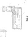
- FIG. 5illustrates an embodiment of a table-based robotic system arranged for a bronchoscopy procedure.
- FIG. 6provides an alternative view of the robotic system of FIG. 5 .
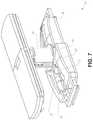
- FIG. 7illustrates an example system configured to stow robotic arm(s).
- FIG. 8illustrates an embodiment of a table-based robotic system configured for a ureteroscopy procedure.
- FIG. 9illustrates an embodiment of a table-based robotic system configured for a laparoscopic procedure.
- FIG. 10illustrates an embodiment of the table-based robotic system of FIGS. 5-9 with pitch or tilt adjustment.
- FIG. 11provides a detailed illustration of the interface between the table and the column of the table-based robotic system of FIGS. 5-10 .
- FIG. 12illustrates an exemplary instrument driver.
- FIG. 13illustrates an exemplary medical instrument with a paired instrument driver.
- FIG. 14illustrates an alternative design for an instrument driver and instrument where the axes of the drive units are parallel to the axis of the elongated shaft of the instrument.
- FIG. 15depicts a block diagram illustrating a localization system that estimates a location of one or more elements of the robotic systems of FIGS. 1-10 , such as the location of the instrument of FIGS. 13-14 , in accordance to an example embodiment.
- FIG. 16illustrates an example command console for a medical robotic system as depicted in FIGS. 1-5 and 8-10 , according to one embodiment.
- FIG. 17illustrates an example of a robotic arm usable with the systems and components depicted in FIGS. 1-16 .
- FIG. 18illustrates another example of a robotic arm usable with the systems and components depicted in FIGS. 1-16 .
- FIG. 19Adepicts the robotic arm of FIG. 17 begin actuated in a first mode of operation.
- FIG. 19Bdepicts a table-based robotic system including a number of robotic arms as depicted in FIG. 17 configured for operating in the first mode for a laparoscopic procedure.
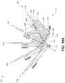
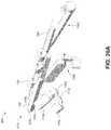
- FIG. 20Adepicts a number of the robotic arms of FIG. 17 configured in a second mode of operation.
- FIG. 20Bdepicts the table-based robotic system of FIG. 19B including some of the robotic arms configured as shown in FIG. 20A for operating in the second mode for an endoscopic procedure.
- FIGS. 21A and 21Bdepict a range of positions for an instrument driver mounted to the robotic arm of FIG. 17 .
- FIGS. 22A-22Ddepict a series of example steps for setting up the robotic arm of FIG. 18 to operate in the first mode depicted in FIG. 19A .
- FIGS. 23A-23Cdepict different sub-modes for operating the robotic arm of FIG. 18 in the first mode depicted in FIG. 19A .
- FIGS. 24A and 24Bdepict different sub-modes for operating the robotic arm of FIG. 17 in the first mode depicted in FIG. 19A .
- FIGS. 25A and 25Bdepict addition of a second instrument driver to the robotic arm of FIG. 18 during operation in the second mode depicted in FIG. 20A .
- FIG. 26depicts the robotic arm of FIG. 18 in a storage configuration.
- FIG. 27depicts various examples of robotic arms according to the present disclosure.
- FIG. 28depicts a flowchart of an example process for operating the robotic arms of FIGS. 17, 18, and 26 .
- aspects of the present disclosuremay be integrated into a robotically-enabled medical system capable of performing a variety of medical procedures, including both minimally invasive, such as laparoscopy, and non-invasive, such as endoscopy, procedures.
- minimally invasivesuch as laparoscopy
- non-invasivesuch as endoscopy
- the systemmay be capable of performing bronchoscopy, ureteroscopy, gastroscopy, etc.
- the systemmay provide additional benefits, such as enhanced imaging and guidance to assist the physician. Additionally, the system may provide the physician with the ability to perform the procedure from an ergonomic position without the need for awkward arm motions and positions. Still further, the system may provide the physician with the ability to perform the procedure with improved ease of use such that one or more of the instruments of the system can be controlled by a single user.
- FIG. 1illustrates an embodiment of a cart-based robotically-enabled system 10 arranged for a diagnostic and/or therapeutic bronchoscopy procedure.
- the system 10may comprise a cart 11 having one or more robotic arms 12 to deliver a medical instrument, such as a steerable endoscope 13 , which may be a procedure-specific bronchoscope for bronchoscopy, to a natural orifice access point (i.e., the mouth of the patient positioned on a table in the present example) to deliver diagnostic and/or therapeutic tools.
- a medical instrumentsuch as a steerable endoscope 13
- a natural orifice access pointi.e., the mouth of the patient positioned on a table in the present example
- the cart 11may be positioned proximate to the patient's upper torso in order to provide access to the access point.
- the robotic arms 12may be actuated to position the bronchoscope relative to the access point.
- the arrangement in FIG. 1may also be utilized when performing a gastro-intestinal (GI) procedure with a gastroscope, a specialized endoscope for GI procedures.
- FIG. 2depicts an example embodiment of the cart in greater detail.
- the robotic arms 12may insert the steerable endoscope 13 into the patient robotically, manually, or a combination thereof.
- the steerable endoscope 13may comprise at least two telescoping parts, such as an inner leader portion and an outer sheath portion, each portion coupled to a separate instrument driver from the set of instrument drivers 28 , each instrument driver coupled to the distal end of an individual robotic arm.
- This linear arrangement of the instrument drivers 28which facilitates coaxially aligning the leader portion with the sheath portion, creates a “virtual rail” 29 that may be repositioned in space by manipulating the one or more robotic arms 12 into different angles and/or positions.
- the virtual rails described hereinare depicted in the Figures using dashed lines, and accordingly the dashed lines do not depict any physical structure of the system.
- Translation of the instrument drivers 28 along the virtual rail 29telescopes the inner leader portion relative to the outer sheath portion or advances or retracts the endoscope 13 from the patient.
- the angle of the virtual rail 29may be adjusted, translated, and pivoted based on clinical application or physician preference. For example, in bronchoscopy, the angle and position of the virtual rail 29 as shown represents a compromise between providing physician access to the endoscope 13 while minimizing friction that results from bending the endoscope 13 into the patient's mouth.
- the endoscope 13may be directed down the patient's trachea and lungs after insertion using precise commands from the robotic system until reaching the target destination or operative site. In order to enhance navigation through the patient's lung network and/or reach the desired target, the endoscope 13 may be manipulated to telescopically extend the inner leader portion from the outer sheath portion to obtain enhanced articulation and greater bend radius.
- the use of separate instrument drivers 28also allows the leader portion and sheath portion to be driven independent of each other.
- the endoscope 13may be directed to deliver a biopsy needle to a target, such as, for example, a lesion or nodule within the lungs of a patient.
- the needlemay be deployed down a working channel that runs the length of the endoscope to obtain a tissue sample to be analyzed by a pathologist.
- additional toolsmay be deployed down the working channel of the endoscope for additional biopsies.
- the endoscope 13may endoscopically deliver tools to resect the potentially cancerous tissue.
- diagnostic and therapeutic treatmentsmay need to be delivered in separate procedures.
- the endoscope 13may also be used to deliver a fiducial to “mark” the location of the target nodule as well. In other instances, diagnostic and therapeutic treatments may be delivered during the same procedure.
- the system 10may also include a movable tower 30 , which may be connected via support cables to the cart 11 to provide support for controls, electronics, fluidics, optics, sensors, and/or power to the cart 11 . Placing such functionality in the tower 30 allows for a smaller form factor cart 11 that may be more easily adjusted and/or re-positioned by an operating physician and his/her staff. Additionally, the division of functionality between the cart/table and the support tower 30 reduces operating room clutter and facilitates improving clinical workflow. While the cart 11 may be positioned close to the patient, the tower 30 may be stowed in a remote location to stay out of the way during a procedure.
- the tower 30may include component(s) of a computer-based control system that stores computer program instructions, for example, within a non-transitory computer-readable storage medium such as a persistent magnetic storage drive, solid state drive, etc.
- the execution of those instructionsmay control the entire system or sub-system(s) thereof.
- the instructionswhen executed by a processor of the computer system, the instructions may cause the components of the robotics system to actuate the relevant carriages and arm mounts, actuate the robotics arms, and control the medical instruments.
- the motors in the joints of the robotics armsmay position the arms into a certain posture.
- the tower 30may also include a pump, flow meter, valve control, and/or fluid access in order to provide controlled irrigation and aspiration capabilities to system that may be deployed through the endoscope 13 . These components may also be controlled using the computer system of tower 30 . In some embodiments, irrigation and aspiration capabilities may be delivered directly to the endoscope 13 through separate cable(s).
- the tower 30may include a voltage and surge protector designed to provide filtered and protected electrical power to the cart 11 , thereby avoiding placement of a power transformer and other auxiliary power components in the cart 11 , resulting in a smaller, more moveable cart 11 .
- the tower 30may also include support equipment for the sensors deployed throughout the robotic system 10 .
- the tower 30may include opto-electronics equipment for detecting, receiving, and processing data received from the optical sensors or cameras throughout the robotic system 10 . In combination with the control system, such opto-electronics equipment may be used to generate real-time images for display in any number of consoles deployed throughout the system, including in the tower 30 .
- the tower 30may also include an electronic subsystem for receiving and processing signals received from deployed electromagnetic (EM) sensors.
- EMelectromagnetic
- the tower 30may also be used to house and position an EM field generator for detection by EM sensors in or on the medical instrument.
- the tower 30may also include a console 31 in addition to other consoles available in the rest of the system, e.g., console mounted on top of the cart.
- the console 31may include a user interface and a display screen, such as a touchscreen, for the physician operator.
- Consoles in system 10are generally designed to provide both robotic controls as well as pre-operative and real-time information of the procedure, such as navigational and localization information of the endoscope 13 .
- the console 31When the console 31 is not the only console available to the physician, it may be used by a second operator, such as a nurse, to monitor the health or vitals of the patient and the operation of system, as well as provide procedure-specific data, such as navigational and localization information.
- the tower 30may be coupled to the cart 11 and endoscope 13 through one or more cables or connections (not shown).
- the support functionality from the tower 30may be provided through a single cable to the cart 11 , simplifying and de-cluttering the operating room.
- specific functionalitymay be coupled in separate cabling and connections. For example, while power may be provided through a single power cable to the cart, the support for controls, optics, fluidics, and/or navigation may be provided through a separate cable.
- FIG. 2provides a detailed illustration of an embodiment of the cart from the cart-based robotically-enabled system shown in FIG. 1 .
- the cart 11generally includes an elongated support structure 14 (often referred to as a “column”), a cart base 15 , and a console 16 at the top of the column 14 .
- the column 14may include one or more carriages, such as a carriage 17 (alternatively “arm support”) for supporting the deployment of one or more robotic arms 12 (three shown in FIG. 2 ).
- the carriage 17may include individually configurable arm mounts that rotate along a perpendicular axis to adjust the base of the robotic arms 12 for better positioning relative to the patient.
- the carriage 17also includes a carriage interface 19 that allows the carriage 17 to vertically translate along the column 14 .
- the carriage interface 19is connected to the column 14 through slots, such as slot 20 , that are positioned on opposite sides of the column 14 to guide the vertical translation of the carriage 17 .
- the slot 20contains a vertical translation interface to position and hold the carriage at various vertical heights relative to the cart base 15 .
- Vertical translation of the carriage 17allows the cart 11 to adjust the reach of the robotic arms 12 to meet a variety of table heights, patient sizes, and physician preferences.
- the individually configurable arm mounts on the carriage 17allow the robotic arm base 21 of robotic arms 12 to be angled in a variety of configurations.
- the slot 20may be supplemented with slot covers that are flush and parallel to the slot surface to prevent dirt and fluid ingress into the internal chambers of the column 14 and the vertical translation interface as the carriage 17 vertically translates.
- the slot coversmay be deployed through pairs of spring spools positioned near the vertical top and bottom of the slot 20 .
- the coversare coiled within the spools until deployed to extend and retract from their coiled state as the carriage 17 vertically translates up and down.
- the spring-loading of the spoolsprovides force to retract the cover into a spool when carriage 17 translates towards the spool, while also maintaining a tight seal when the carriage 17 translates away from the spool.
- the coversmay be connected to the carriage 17 using, for example, brackets in the carriage interface 19 to ensure proper extension and retraction of the cover as the carriage 17 translates.
- the column 14may internally comprise mechanisms, such as gears and motors, that are designed to use a vertically aligned lead screw to translate the carriage 17 in a mechanized fashion in response to control signals generated in response to user inputs, e.g., inputs from the console 16 .
- the robotic arms 12may generally comprise robotic arm bases 21 and end effectors 22 , separated by a series of linkages 23 that are connected by a series of joints 24 , each joint comprising an independent actuator, each actuator comprising an independently controllable motor.
- Each independently controllable jointrepresents an independent degree of freedom available to the robotic arm.
- Each of the arms 12have seven joints, and thus provide seven degrees of freedom. A multitude of joints result in a multitude of degrees of freedom, allowing for “redundant” degrees of freedom. Redundant degrees of freedom allow the robotic arms 12 to position their respective end effectors 22 at a specific position, orientation, and trajectory in space using different linkage positions and joint angles. This allows for the system to position and direct a medical instrument from a desired point in space while allowing the physician to move the arm joints into a clinically advantageous position away from the patient to create greater access, while avoiding arm collisions.
- the cart base 15balances the weight of the column 14 , carriage 17 , and arms 12 over the floor. Accordingly, the cart base 15 houses heavier components, such as electronics, motors, power supply, as well as components that either enable movement and/or immobilize the cart.
- the cart base 15includes rollable wheel-shaped casters 25 that allow for the cart to easily move around the room prior to a procedure. After reaching the appropriate position, the casters 25 may be immobilized using wheel locks to hold the cart 11 in place during the procedure.
- the console 16allows for both a user interface for receiving user input and a display screen (or a dual-purpose device such as, for example, a touchscreen 26 ) to provide the physician user with both pre-operative and intra-operative data.
- Potential pre-operative data on the touchscreen 26may include pre-operative plans, navigation and mapping data derived from pre-operative computerized tomography (CT) scans, and/or notes from pre-operative patient interviews.
- Intra-operative data on displaymay include optical information provided from the tool, sensor and coordinate information from sensors, as well as vital patient statistics, such as respiration, heart rate, and/or pulse.
- the console 16may be positioned and tilted to allow a physician to access the console from the side of the column 14 opposite carriage 17 . From this position the physician may view the console 16 , robotic arms 12 , and patient while operating the console 16 from behind the cart 11 .
- the console 16also includes a handle 27 to assist with maneuvering and stabilizing cart 11 .
- FIG. 3illustrates an embodiment of a robotically-enabled system 10 arranged for ureteroscopy.
- the cart 11may be positioned to deliver a ureteroscope 32 , a procedure-specific endoscope designed to traverse a patient's urethra and ureter, to the lower abdominal area of the patient.
- the ureteroscope 32may be directly aligned with the patient's urethra to reduce friction and forces on the sensitive anatomy in the area.
- the cart 11may be aligned at the foot of the table to allow the robotic arms 12 to position the ureteroscope 32 for direct linear access to the patient's urethra. From the foot of the table, the robotic arms 12 may insert the ureteroscope 32 along the virtual rail 33 directly into the patient's lower abdomen through the urethra.
- the ureteroscope 32may be navigated into the bladder, ureters, and/or kidneys for diagnostic and/or therapeutic applications.
- the ureteroscope 32may be directed into the ureter and kidneys to break up kidney stone build up using laser or ultrasonic lithotripsy device deployed down the working channel of the ureteroscope 32 .
- the resulting stone fragmentsmay be removed using baskets deployed down the ureteroscope 32 .
- FIG. 4illustrates an embodiment of a robotically-enabled system similarly arranged for a vascular procedure.
- the system 10may be configured such the cart 11 may deliver a medical instrument 34 , such as a steerable catheter, to an access point in the femoral artery in the patient's leg.
- the femoral arterypresents both a larger diameter for navigation as well as relatively less circuitous and tortuous path to the patient's heart, which simplifies navigation.
- the cart 11may be positioned towards the patient's legs and lower abdomen to allow the robotic arms 12 to provide a virtual rail 35 with direct linear access to the femoral artery access point in the patient's thigh/hip region.
- the medical instrument 34may be directed and inserted by translating the instrument drivers 28 .
- the cartmay be positioned around the patient's upper abdomen in order to reach alternative vascular access points, such as, for example, the carotid and brachial arteries near the shoulder and wrist.
- Embodiments of the robotically-enabled medical systemmay also incorporate the patient's table. Incorporation of the table reduces the amount of capital equipment within the operating room by removing the cart, which allows greater access to the patient.
- FIG. 5illustrates an embodiment of such a robotically-enabled system arranged for a bronchoscopy procedure.
- System 36includes a support structure or column 37 for supporting platform 38 (shown as a “table” or “bed”) over the floor.
- the end effectors of the robotic arms 39 of the system 36comprise instrument drivers 42 that are designed to manipulate an elongated medical instrument, such as a bronchoscope 40 in FIG. 5 , through or along a virtual rail 41 formed from the linear alignment of the instrument drivers 42 .
- a C-arm for providing fluoroscopic imagingmay be positioned over the patient's upper abdominal area by placing the emitter and detector around table 38 .
- FIG. 6provides an alternative view of the system 36 without the patient and medical instrument for discussion purposes.
- the column 37may include one or more carriages 43 shown as ring-shaped in the system 36 , from which the one or more robotic arms 39 may be based.
- the carriages 43may translate along a vertical column interface 44 that runs the length of the column 37 to provide different vantage points from which the robotic arms 39 may be positioned to reach the patient.
- the carriage(s) 43may rotate around the column 37 using a mechanical motor positioned within the column 37 to allow the robotic arms 39 to have access to multiples sides of the table 38 , such as, for example, both sides of the patient.
- the carriagesmay be individually positioned on the column and may translate and/or rotate independent of the other carriages.
- carriages 43need not surround the column 37 or even be circular, the ring-shape as shown facilitates rotation of the carriages 43 around the column 37 while maintaining structural balance. Rotation and translation of the carriages 43 allows the system to align the medical instruments, such as endoscopes and laparoscopes, into different access points on the patient.
- the arms 39may be mounted on the carriages through a set of arm mounts 45 comprising a series of joints that may individually rotate and/or telescopically extend to provide additional configurability to the robotic arms 39 .
- the arm mounts 45may be positioned on the carriages 43 such that, when the carriages 43 are appropriately rotated, the arm mounts 45 may be positioned on either the same side of table 38 (as shown in FIG. 6 ), on opposite sides of table 38 (as shown in FIG. 9 ), or on adjacent sides of the table 38 (not shown).
- the column 37structurally provides support for the table 38 , and a path for vertical translation of the carriages. Internally, the column 37 may be equipped with lead screws for guiding vertical translation of the carriages, and motors to mechanize the translation of said carriages based the lead screws. The column 37 may also convey power and control signals to the carriage 43 and robotic arms 39 mounted thereon.
- the table base 46serves a similar function as the cart base 15 in cart 11 shown in FIG. 2 , housing heavier components to balance the table/bed 38 , the column 37 , the carriages 43 , and the robotic arms 39 .
- the table base 46may also incorporate rigid casters to provide stability during procedures. Deployed from the bottom of the table base 46 , the casters may extend in opposite directions on both sides of the base 46 and retract when the system 36 needs to be moved.
- the system 36may also include a tower (not shown) that divides the functionality of system 36 between table and tower to reduce the form factor and bulk of the table.
- the towermay provide a variety of support functionalities to table, such as processing, computing, and control capabilities, power, fluidics, and/or optical and sensor processing.
- the towermay also be movable to be positioned away from the patient to improve physician access and de-clutter the operating room. Additionally, placing components in the tower allows for more storage space in the table base for potential stowage of the robotic arms.
- the towermay also include a console that provides both a user interface for user input, such as keyboard and/or pendant, as well as a display screen (or touchscreen) for pre-operative and intra-operative information, such as real-time imaging, navigation, and tracking information.
- a table basemay stow and store the robotic arms when not in use.
- FIG. 7illustrates a system 47 that stows robotic arms in an embodiment of the table-based system.
- carriages 48may be vertically translated into base 49 to stow robotic arms 50 , arm mounts 51 , and the carriages 48 within the base 49 .
- Base covers 52may be translated and retracted open to deploy the carriages 48 , arm mounts 51 , and arms 50 around column 53 , and closed to stow to protect them when not in use.
- the base covers 52may be sealed with a membrane 54 along the edges of its opening to prevent dirt and fluid ingress when closed.
- FIG. 8illustrates an embodiment of a robotically-enabled table-based system configured for a ureteroscopy procedure.
- the table 38may include a swivel portion 55 for positioning a patient off-angle from the column 37 and table base 46 .
- the swivel portion 55may rotate or pivot around a pivot point (e.g., located below the patient's head) in order to position the bottom portion of the swivel portion 55 away from the column 37 .
- the pivoting of the swivel portion 55allows a C-arm (not shown) to be positioned over the patient's lower abdomen without competing for space with the column (not shown) below table 38 .
- the robotic arms 39may directly insert a ureteroscope 56 along a virtual rail 57 into the patient's groin area to reach the urethra.
- stirrups 58may also be fixed to the swivel portion 55 of the table 38 to support the position of the patient's legs during the procedure and allow clear access to the patient's groin area.
- FIG. 9illustrates an embodiment of a robotically-enabled table-based system configured for a laparoscopic procedure. As shown in FIG.
- the carriages 43 of the system 36may be rotated and vertically adjusted to position pairs of the robotic arms 39 on opposite sides of the table 38 , such that laparoscopes 59 may be positioned using the arm mounts 45 to be passed through minimal incisions on both sides of the patient to reach his/her abdominal cavity.
- FIG. 10illustrates an embodiment of the robotically-enabled medical system with pitch or tilt adjustment.
- the system 36may accommodate tilt of the table 38 to position one portion of the table at a greater distance from the floor than the other.
- the arm mounts 45may rotate to match the tilt such that the arms 39 maintain the same planar relationship with table 38 .
- the column 37may also include telescoping portions 60 that allow vertical extension of column 37 to keep the table 38 from touching the floor or colliding with base 46 .
- FIG. 11provides a detailed illustration of the interface between the table 38 and the column 37 .
- Pitch rotation mechanism 61may be configured to alter the pitch angle of the table 38 relative to the column 37 in multiple degrees of freedom.
- the pitch rotation mechanism 61may be enabled by the positioning of orthogonal axes 1 , 2 at the column-table interface, each axis actuated by a separate motor 2 , 4 responsive to an electrical pitch angle command. Rotation along one screw 5 would enable tilt adjustments in one axis 1 , while rotation along the other screw 6 would enable tilt adjustments along the other axis 2 .
- pitch adjustmentsare particularly useful when trying to position the table in a Trendelenburg position, i.e., position the patient's lower abdomen at a higher position from the floor than the patient's lower abdomen, for lower abdominal surgery.
- the Trendelenburg positioncauses the patient's internal organs to slide towards his/her upper abdomen through the force of gravity, clearing out the abdominal cavity for minimally invasive tools to enter and perform lower abdominal surgical procedures, such as laparoscopic prostatectomy.
- the end effectors of the system's robotic armscomprise (i) an instrument driver (alternatively referred to as “instrument drive mechanism” or “instrument device manipulator”) that incorporate electro-mechanical means for actuating the medical instrument and (ii) a removable or detachable medical instrument which may be devoid of any electro-mechanical components, such as motors.
- instrument driveralternatively referred to as “instrument drive mechanism” or “instrument device manipulator”
- instrument device manipulatora removable or detachable medical instrument which may be devoid of any electro-mechanical components, such as motors.
- FIG. 12illustrates an example instrument driver.
- instrument driver 62Positioned at the distal end of a robotic arm, instrument driver 62 comprises of one or more drive units 63 arranged with parallel axes to provide controlled torque to a medical instrument via drive shafts 64 .
- Each drive unit 63comprises an individual drive shaft 64 for interacting with the instrument, a gear head 65 for converting the motor shaft rotation to a desired torque, a motor 66 for generating the drive torque, an encoder 67 to measure the speed of the motor shaft and provide feedback to the control circuitry, and control circuity 68 for receiving control signals and actuating the drive unit.
- Each drive unit 63being independent controlled and motorized, the instrument driver 62 may provide multiple (four as shown in FIG. 12 ) independent drive outputs to the medical instrument.
- the control circuitry 68would receive a control signal, transmit a motor signal to the motor 66 , compare the resulting motor speed as measured by the encoder 67 with the desired speed, and modulate the motor signal to generate the desired torque
- the robotic systemmay incorporate a drive interface, such as a sterile adapter connected to a sterile drape, that sits between the instrument driver and the medical instrument.
- a drive interfacesuch as a sterile adapter connected to a sterile drape
- the chief purpose of the sterile adapteris to transfer angular motion from the drive shafts of the instrument driver to the drive inputs of the instrument while maintaining physical separation, and thus sterility, between the drive shafts and drive inputs.
- an example sterile adaptermay comprise of a series of rotational inputs and outputs intended to be mated with the drive shafts of the instrument driver and drive inputs on the instrument.
- the sterile drapecomprised of a thin, flexible material such as transparent or translucent plastic, is designed to cover the capital equipment, such as the instrument driver, robotic arm, and cart (in a cart-based system) or table (in a table-based system).
- the capital equipmentsuch as the instrument driver, robotic arm, and cart (in a cart-based system) or table (in a table-based system).
- Use of the drapewould allow the capital equipment to be positioned proximate to the patient while still being located in an area not requiring sterilization (i.e., non-sterile field).
- the medical instrumentmay interface with the patient in an area requiring sterilization (i.e., sterile field).
- FIG. 13illustrates an example medical instrument with a paired instrument driver.
- medical instrument 70comprises an elongated shaft 71 (or elongate body) and an instrument base 72 .
- the instrument base 72also referred to as an “instrument handle” due to its intended design for manual interaction by the physician, may generally comprise rotatable drive inputs 73 , e.g., receptacles, pulleys or spools, that are designed to be mated with drive outputs 74 that extend through a drive interface on instrument driver 75 at the distal end of robotic arm 76 .
- the mated drive inputs 73 of instrument base 72may share axes of rotation with the drive outputs 74 in the instrument driver 75 to allow the transfer of torque from drive outputs 74 to drive inputs 73 .
- the drive outputs 74may comprise splines that are designed to mate with receptacles on the drive inputs 73 .
- the elongated shaft 71is designed to be delivered through either an anatomical opening or lumen, e.g., as in endoscopy, or a minimally invasive incision, e.g., as in laparoscopy.
- the elongated shaft 66may be either flexible (e.g., having properties similar to an endoscope) or rigid (e.g., having properties similar to a laparoscope) or contain a customized combination of both flexible and rigid portions.
- the distal end of a rigid elongated shaftmay be connected to an end effector comprising a jointed wrist formed from a clevis with an axis of rotation and a surgical tool, such as, for example, a grasper or scissors, that may be actuated based on force from the tendons as the drive inputs rotate in response to torque received from the drive outputs 74 of the instrument driver 75 .
- a surgical toolsuch as, for example, a grasper or scissors
- the distal end of a flexible elongated shaftmay include a steerable or controllable bending section that may be articulated and bent based on torque received from the drive outputs 74 of the instrument driver 75 .
- Torque from the instrument driver 75is transmitted down the elongated shaft 71 using tendons within the shaft 71 .
- These individual tendonssuch as pull wires, may be individually anchored to individual drive inputs 73 within the instrument handle 72 .
- the tendonsare directed down one or more pull lumens within the elongated shaft 71 and anchored at the distal portion of the elongated shaft 71 .
- these tendonsmay be coupled to a distally mounted end effector, such as a wrist, grasper, or scissor. Under such an arrangement, torque exerted on drive inputs 73 would transfer tension to the tendon, thereby causing the end effector to actuate in some way.
- the tendonmay cause a joint to rotate about an axis, thereby causing the end effector to move in one direction or another.
- the tendonmay be connected to one or more jaws of a grasper at distal end of the elongated shaft 71 , where tension from the tendon cause the grasper to close.
- the tendonsmay be coupled to a bending or articulating section positioned along the elongated shaft 71 (e.g., at the distal end) via adhesive, control ring, or other mechanical fixation.
- a bending or articulating sectionpositioned along the elongated shaft 71 (e.g., at the distal end) via adhesive, control ring, or other mechanical fixation.
- torque exerted on drive inputs 73would be transmitted down the tendons, causing the softer, bending section (sometimes referred to as the articulable section or region) to bend or articulate.
- the angle of the spiraling and/or spacing there betweenmay be altered or engineered for specific purposes, wherein tighter spiraling exhibits lesser shaft compression under load forces, while lower amounts of spiraling results in greater shaft compression under load forces, but also exhibits limits bending.
- the pull lumensmay be directed parallel to the longitudinal axis of the elongated shaft 71 to allow for controlled articulation in the desired bending or articulable sections.
- the elongated shaft 71houses a number of components to assist with the robotic procedure.
- the shaftmay comprise of a working channel for deploying surgical tools, irrigation, and/or aspiration to the operative region at the distal end of the shaft 71 .
- the shaft 71may also accommodate wires and/or optical fibers to transfer signals to/from an optical assembly at the distal tip, which may include of an optical camera.
- the shaft 71may also accommodate optical fibers to carry light from proximally-located light sources, such as light emitting diodes, to the distal end of the shaft.
- the distal tipmay also comprise the opening of a working channel for delivering tools for diagnostic and/or therapy, irrigation, and aspiration to an operative site.
- the distal tipmay also include a port for a camera, such as a fiberscope or a digital camera, to capture images of an internal anatomical space.
- the distal tipmay also include ports for light sources for illuminating the anatomical space when using the camera.
- the drive shaft axesand thus the drive input axes, are orthogonal to the axis of the elongated shaft.
- This arrangementcomplicates roll capabilities for the elongated shaft 71 .
- Rolling the elongated shaft 71 along its axis while keeping the drive inputs 73 staticresults in undesirable tangling of the tendons as they extend off the drive inputs 73 and enter pull lumens within the elongate shaft 71 .
- the resulting entanglement of such tendonsmay disrupt any control algorithms intended to predict movement of the flexible elongate shaft during an endoscopic procedure.
- FIG. 14illustrates an alternative design for an instrument driver and instrument where the axes of the drive units are parallel to the axis of the elongated shaft of the instrument.
- a circular instrument driver 80comprises four drive units with their drive outputs 81 aligned in parallel at the end of a robotic arm 82 .
- the drive units, and their respective drive outputs 81are housed in a rotational assembly 83 of the instrument driver 80 that is driven by one of the drive units within the assembly 83 .
- the rotational assembly 83rotates along a circular bearing that connects the rotational assembly 83 to the non-rotational portion 84 of the instrument driver.
- Power and controls signalsmay be communicated from the non-rotational portion 84 of the instrument driver 80 to the rotational assembly 83 through electrical contacts may be maintained through rotation by a brushed slip ring connection (not shown).
- the rotational assembly 83may be responsive to a separate drive unit that is integrated into the non-rotatable portion 84 , and thus not in parallel to the other drive units.
- the rotational mechanism 83allows the instrument driver 80 to rotate the drive units, and their respective drive outputs 81 , as a single unit around an instrument driver axis 85 .
- an instrument 86may comprise of an elongated shaft portion 88 and an instrument base 87 (shown with a transparent external skin for discussion purposes) comprising a plurality of drive inputs 89 (such as receptacles, pulleys, and spools) that are configured to receive the drive outputs 81 in the instrument driver 80 .
- instrument shaft 88extends from the center of instrument base 87 with an axis substantially parallel to the axes of the drive inputs 89 , rather than orthogonal as in the design of FIG. 13 .
- the medical instrument 86When coupled to the rotational assembly 83 of the instrument driver 80 , the medical instrument 86 , comprising instrument base 87 and instrument shaft 88 , rotates in combination with the rotational assembly 83 about the instrument driver axis 85 . Since the instrument shaft 88 is positioned at the center of instrument base 87 , the instrument shaft 88 is coaxial with instrument driver axis 85 when attached. Thus, rotation of the rotational assembly 83 causes the instrument shaft 88 to rotate about its own longitudinal axis. Moreover, as the instrument base 87 rotates with the instrument shaft 88 , any tendons connected to the drive inputs 89 in the instrument base 87 are not tangled during rotation. Accordingly, the parallelism of the axes of the drive outputs 81 , drive inputs 89 , and instrument shaft 88 allows for the shaft rotation without tangling any control tendons.
- the robotic systems contemplated by this disclosurecan provide for non-radiation-based navigational and localization means to reduce physician exposure to radiation and reduce the amount of equipment within the operating room.
- the term “localization”may refer to determining and/or monitoring the position of objects in a reference coordinate system. Technologies such as pre-operative mapping, computer vision, real-time EM tracking, and robot command data may be used individually or in combination to achieve a radiation-free operating environment. In other cases, where radiation-based imaging modalities are still used, the pre-operative mapping, computer vision, real-time EM tracking, and robot command data may be used individually or in combination to improve upon the information obtained solely through radiation-based imaging modalities.
- FIG. 15is a block diagram illustrating a localization system 90 that estimates a location of one or more elements of the robotic system, such as the location of the instrument, in accordance to an example embodiment.
- the localization system 90may be a set of one or more computer devices configured to execute one or more instructions.
- the computer devicesmay be embodied by a processor (or processors) and computer-readable memory in one or more components discussed above.
- the computer devicesmay be in the tower 30 shown in FIG. 1 , the cart shown in FIGS. 1-4 , the beds shown in FIGS. 5-10 , etc.
- the localization system 90may include a localization module 95 that processes input data 91 - 94 to generate location data 96 for the distal tip of a medical instrument.
- the location data 96may be data or logic that represents a location and/or orientation of the distal end of the instrument relative to a frame of reference.
- the frame of referencecan be a frame of reference relative to the anatomy of the patient or to a known object, such as an EM field generator (see discussion below for the EM field generator).
- Pre-operative mappingmay be accomplished through the use of the collection of low dose CT scans.
- Pre-operative CT scansgenerate two-dimensional images, each representing a “slice” of a cutaway view of the patient's internal anatomy.
- image-based models for anatomical cavities, spaces and structures of the patient's anatomy, such as a patient lung networkmay be generated.
- Techniquessuch as center-line geometry may be determined and approximated from the CT images to develop a three-dimensional volume of the patient's anatomy, referred to as preoperative model data 91 .
- center-line geometryis discussed in U.S. patent application Ser. No. 14/523,760, the contents of which are herein incorporated in its entirety.
- Network topological modelsmay also be derived from the CT-images, and are particularly appropriate for bronchoscopy.
- the instrumentmay be equipped with a camera to provide vision data 92 .
- the localization module 95may process the vision data to enable one or more vision-based location tracking.
- the preoperative model datamay be used in conjunction with the vision data 92 to enable computer vision-based tracking of the medical instrument (e.g., an endoscope or an instrument advance through a working channel of the endoscope).
- the robotic systemmay generate a library of expected endoscopic images from the model based on the expected path of travel of the endoscope, each image linked to a location within the model. Intra-operatively, this library may be referenced by the robotic system in order to compare real-time images captured at the camera (e.g., a camera at a distal end of the endoscope) to those in the image library to assist localization.
- Some computer vision-based tracking techniquesuse feature tracking to determine motion of the camera, and thus the endoscope.
- Some feature of the localization module 95may identify circular geometries in the preoperative model data 91 that correspond to anatomical lumens and track the change of those geometries to determine which anatomical lumen was selected, as well as the relative rotational and/or translational motion of the camera.
- Use of a topological mapmay further enhance vision-based algorithms or techniques.
- Optical flowanother computer vision-based technique, may analyze the displacement and translation of image pixels in a video sequence in the vision data 92 to infer camera movement. Through the comparison of multiple frames over multiple iterations, movement and location of the camera (and thus the endoscope) may be determined.
- the localization module 95may use real-time EM tracking to generate a real-time location of the endoscope in a global coordinate system that may be registered to the patient's anatomy, represented by the preoperative model.
- EM trackingan EM sensor (or tracker) comprising of one or more sensor coils embedded in one or more locations and orientations in a medical instrument (e.g., an endoscopic tool) measures the variation in the EM field created by one or more static EM field generators positioned at a known location.
- the location information detected by the EM sensorsis stored as EM data 93 .
- the EM field generator(or transmitter), may be placed close to the patient to create a low intensity magnetic field that the embedded sensor may detect.
- the magnetic fieldinduces small currents in the sensor coils of the EM sensor, which may be analyzed to determine the distance and angle between the EM sensor and the EM field generator.
- These distances and orientationsmay be intra-operatively “registered” to the patient anatomy (e.g., the preoperative model) in order to determine the geometric transformation that aligns a single location in the coordinate system with a position in the pre-operative model of the patient's anatomy.
- an embedded EM tracker in one or more positions of the medical instrumente.g., the distal tip of an endoscope
- Robotic command and kinematics data 94may also be used by the localization module 95 to provide localization data 96 for the robotic system.
- Device pitch and yaw resulting from articulation commandsmay be determined during pre-operative calibration. Intra-operatively, these calibration measurements may be used in combination with known insertion depth information to estimate the position of the instrument. Alternatively, these calculations may be analyzed in combination with EM, vision, and/or topological modeling to estimate the position of the medical instrument within the network.
- FIG. 15shows, a number of other input data can be used by the localization module 95 .
- an instrument utilizing shape-sensing fibercan provide shape data that the localization module 95 can use to determine the location and shape of the instrument.
- the localization module 95may use the input data 91 - 94 in combination(s). In some cases, such a combination may use a probabilistic approach where the localization module 95 assigns a confidence weight to the location determined from each of the input data 91 - 94 . Thus, where the EM data may not be reliable (as may be the case where there is EM interference) the confidence of the location determined by the EM data 93 can be decrease and the localization module 95 may rely more heavily on the vision data 92 and/or the robotic command and kinematics data 94 .
- the robotic systems discussed hereinmay be designed to incorporate a combination of one or more of the technologies above.
- the robotic system's computer-based control systembased in the tower, bed and/or cart, may store computer program instructions, for example, within a non-transitory computer-readable storage medium such as a persistent magnetic storage drive, solid state drive, or the like, that, upon execution, cause the system to receive and analyze sensor data and user commands, generate control signals throughout the system, and display the navigational and localization data, such as the position of the instrument within the global coordinate system, anatomical map, etc.
- Embodiments of the disclosurerelate to versatile robotic systems and operational techniques associated with a single robotic system to be capable of performing multiple types of medical procedures. As described above, due to the varying requirements of different medical procedures, robotic systems may be designed and built specifically for performing a single medical procedure, and as a result may be unable to satisfy the requirements for performing other medical procedures.
- one existing systemis purpose-built for laparoscopic surgery.
- the existing systemis designed with robotic arm kinematics including a mechanically-constrained remote center provided so that the robotic arm inserts, pitches, and yaws a medical instrument with respect to the remote center.
- the mechanically-constrained remote centeris effected by multiple joints that are connected to one another by bands, such that all joints are controlled by a single motor. While the inertia of the robotic arm is generally low and the robotic arm is able to maintain the remote center even under loss of power, a potential drawback of this design is that it is not used for performing non-laparoscopic procedures.
- the mechanical remote centerit may be difficult to utilize the robotic arm for endoscopic procedures because the mechanically constrained remote center makes it hard to align the robotic arm along a virtual rail.
- the bands used to create the mechanical remote centerprevent compact storage of the robotic arm.
- a robotic arm according to the present disclosureincludes a versatile kinematic chain and is controlled by computer-implemented instructions that enable the robotic arm to operate in a variety of modes, with different modes usable for different types of medical procedures.
- the kinematic chainincludes a number of motorized joints coupled by linkages in a serial fashion, with a revolute motorized joint at the proximal end of the robotic arm (e.g., closest to setup joints or a base of the robotic system), a prismatic motorized joint at the distal end of the robotic arm (e.g., closest to the medical instrument), and a number of additional motorized joints positioned serially between the first and second motorized joints.
- the additional motorized jointscan be either revolute or prismatic as explained in more detail below.
- the robotic armcan be operated in a first mode with respect to a remote center to perform laparoscopic procedures and can be operated in a second mode with respect to a virtual rail to perform endoscopic procedures. While the present disclosure provides examples of first and second operating modes for laparoscopic and endoscopic procedures, respectively, the disclosed robotic systems can also be used to perform other types of medical procedures.
- FIG. 16illustrates an example command console 200 for a medical robotics system as described herein, for example in a medical robotic system as depicted in FIGS. 1-5 and 8-10 .
- the command console 200that can be used, for example, as the command console 105 in the example operating environment 100 .
- the command console 200includes a console base 201 , display modules 202 , e.g., monitors, and control modules, e.g., a keyboard 203 and joystick 204 .
- one or more of the command console 200 functionalitymay be integrated into a base of a medical robotic system as depicted in FIGS. 1-5 and 8-10 or another system communicatively coupled to the medical robotic system.
- a user 205e.g., a physician, remotely controls the medical robotic system from an ergonomic position using the command console 200 .
- the console base 201may include controller 206 including a one or more processors and memories, and optionally one or more data buses and associated data communication ports. Controller 206 is responsible for interpreting and processing signals such as robotic position data, camera imagery, and tracking sensor data, e.g., from a medical instrument such as endoscope 13 , ureteroscope 32 , medical instrument 34 , laparoscope 59 , gastroscope, bronchoscope, or another procedure-specific medical instrument.
- the memory of the controller 206can store instructions for operation of the medical instruments and robotic systems described herein.
- both the console base 201 and the base of the medical robotic systemcan perform signal processing for load-balancing, and thus the controller 206 may be split between different system components.
- the controller 206may also process commands and instructions provided by the user 205 through the control modules 203 and 204 .
- the control modulesmay include other devices, for example, computer mice, trackpads, trackballs, control pads, controls such as handheld remote controllers, and sensors (e.g., motion sensors or cameras) that capture hand gestures and finger gestures.
- the control modulesinclude a pair of seven degree-of-freedom (“7 DOF”) haptic masters.
- a haptic masteris a force controlled haptic interface that translates input (e.g., force applied by a human user) to output (e.g., displacement of the end effector of the robotic system) and also provides tactile feedback back to the user.
- a 7 DOF haptic mastercan provide three degrees of motion in the X, Y, Z directions and four degrees of motion of the pitch, yaw, roll and articulation.
- a controlcan include a set of user inputs (e.g., buttons, joysticks, directional pads, etc.) mapped to an operation of the instrument (e.g., articulation, driving, water irrigation, etc.).
- the user 205can control a medical instrument via a robotic arm as described herein using the command console 200 in a velocity mode or position control mode.
- velocity modethe user 205 directly controls pitch and yaw motion of a distal end of the medical instrument based on direct manual control using the control modules.
- movement on the joystick 204may be mapped to yaw and pitch movement in the distal end of the medical instrument.
- the joystick 204can provide haptic feedback to the user 205 .
- the joystick 204may vibrate to indicate that the medical instrument cannot further translate or rotate in a certain direction.
- the command console 200can also provide visual feedback (e.g., pop-up messages) and/or audio feedback (e.g., beeping) to indicate that the medical instrument has reached maximum translation or rotation.
- the command console 200uses a 3D map of a patient luminal network and input from navigational sensors as described herein to control a medical instrument.
- the command console 200provides control signals to robotic arms of the medical robotic system to manipulate the medical instrument to a target location. Due to the reliance on the 3D map, position control mode may require accurate mapping of the anatomy of the patient.
- users 205can manually manipulate robotic arms of the medical robotic system without using the command console 200 .
- the users 205may move the robotic arms, medical instruments, and other surgical equipment to access a patient.
- the medical robotic systemmay rely on force feedback and inertia control from the users 205 to determine appropriate configuration of the robotic arms and equipment.
- the displays 202may include electronic monitors (e.g., LCD displays, LED displays, touch-sensitive displays), virtual reality viewing devices, e.g., goggles or glasses, and/or other display devices.
- electronic monitorse.g., LCD displays, LED displays, touch-sensitive displays
- virtual reality viewing devicese.g., goggles or glasses
- the displaycan include a compact stereo viewer having a pair of apertures through which a user can view a stereoscopic image without the aid of glasses or goggles. This can be used, for example, to display a stereoscopic laparoscopic image.
- the display modules 202are integrated with the control modules, for example, as a tablet device with a touchscreen.
- one of the displays 202can display a 3D model of the patient's luminal network and virtual navigation information (e.g., a virtual representation of the end of the endoscope within the model based on EM sensor position) while the other of the displays 202 can display image information received from the camera or another sensing device at the end of the medical instrument.
- the user 205can both view data and input commands to the medical robotic system using the integrated displays 202 and control modules.
- the displays 202can display 2D renderings of 3D images and/or 3D images using a stereoscopic device, e.g., a visor or goggles.
- the 3D imagesprovide an “endo view” (i.e., endoscopic view), which is a computer 3D model illustrating the anatomy of a patient.
- the “endo view”provides a virtual environment of the patient's interior and an expected location of a medical instrument inside the patient.
- a user 205compares the “endo view” model to actual images captured by a camera to help mentally orient and confirm that the medical instrument is in the correct—or approximately correct—location within the patient.
- the “endo view”provides information about anatomical structures, e.g., the shape of airways, circulatory vessels, or an intestine or colon of the patient, around the distal end of the medical instrument.
- the display modules 202can simultaneously display the 3D model and CT scans of the anatomy the around distal end of the medical instrument. Further, the display modules 202 may overlay the already determined navigation paths of the medical instrument on the 3D model and CT scans.
- a model of the medical instrumentis displayed with the 3D models to help indicate a status of a surgical procedure.
- the CT scansidentify a lesion in the anatomy where a biopsy may be necessary.
- the display modules 202may show a reference image captured by the medical instrument corresponding to the current location of the medical instrument.
- the display modules 202may automatically display different views of the model of the medical instrument depending on user settings and a particular surgical procedure.
- the display modules 202show an overhead fluoroscopic view of the medical instrument during a navigation step as the medical instrument approaches an operative region of a patient.
- Such user-guided movement of the medical instrumentcan be constrained according to various pre-defined operating modes for a robotic arm as described herein.
- FIG. 17illustrates an example of a robotic arm 1700 usable with the systems and components depicted in FIGS. 1-16 .
- the robotic arm 1700comprises an RRRPP serial chain manipulator, with “R” referring to a revolute joint and “P” referring to a prismatic joint, with such joint labeling beginning at the proximal-most joint 1705 A and moving serially along the robotic arm towards the distal-most joint 1705 E.
- the robotic arm 1700can be configured for use as a low-inertia remote center laparoscopy system or as a virtual rail endoscopic system.
- the robotic arm 1700includes a number of motorized joints 1705 A- 1705 E connected in serial fashion by linkages 1710 A- 1710 D.
- the first linkage 1710 Aconnects the first motorized joint 1705 A and the third motorized joint 1705 B
- the second linkage 1710 Bconnects the third motorized joint 1705 B to the fourth motorized joint 1705 C
- the third linkage 1710 Cconnects the fourth motorized joint 1705 C to the fifth motorized joint 1705 D
- the fourth linkage 1710 Dconnects the fifth motorized joint 1705 D to the second motorized joint 1705 E.
- a first motorized joint 1705 A at the proximal end of the robotic armis a revolute joint that causes rotational motion of medical instrument 1725 around yaw axis 1735 A.
- a second motorized joint 1705 E at the distal end of the robotic armis a prismatic joint that moves linearly along distal face 1715 B of the fourth linkage 1710 D. Additional motorized joints 1705 B, 1705 C, 1705 D are positioned serially between the first and second motorized joints.
- the fifth motorized 1705 D jointis a prismatic joint that moves linearly along the proximal face 1715 A of the fourth linkage 1710 D.
- the axes of prismatic joints 1705 D and 1705 Eare depicted as being parallel to each other due to the shape of the fourth linkage 1710 D, however in other embodiments the axes may not be parallel and the shape of the fourth linkage 1710 D may vary accordingly.
- the third motorized joint 1705 B and fourth motorized joint 1705 Care revolute joints that each rotate in a plane positioned orthogonally to the plane of rotation of the first motorized joint 1705 A. Actuation of the third motorized joint 1705 B and fourth motorized joint 1705 C can cause the medical instrument 1725 to rotate about pitch axis 1735 C.
- Each motorized joint 1705 A- 1705 Ecan comprise a motor, a position sensor, and a gearbox.
- the motorcan be an interior permanent magnet motor including a stator, a rotor rotatable within the stator, and a plurality of windings wound through the stator and configured to carry one or more phases of electrical current.
- the rotorcan comprise a magnetically permeable material and at least one permanent magnet embedded within the magnetically permeable material.
- the position sensoris an optical encoder positioned with a field of view encompassing the rotor such that the optical encoder can capture image data representative of the rotor, the image data usable to determine a position of the rotor.
- suitable position sensorsinclude closed loop position control systems that monitor the current in one or more of the windings of a motor (for example via a Hall sensor or other current sensor), as well as angular joint sensors that generate data usable to determine the angle between adjacent linkages (for example one or more of accelerometers, gyroscopes, magnetometers, conductive fibers, etc.). Output from the position sensors of each of the motorized joints 1705 A- 1705 E can be used by the controller 206 to control actuation of the robotic arm 1700 in the operational modes described herein.
- the gearboxcan include a number of gears to achieve a desired gear ratio for each joint.
- One example jointcan have a 100:1 to 150:1 gear ratio in order to achieve the desired stiffness for operation during endoscopic medical procedures.
- the gearboxcan be a harmonic gearbox using strain wave gearing and thus provides advantages over traditional gear-based gearboxes due to having low or no backlash, high compactness, and light weight.
- An instrument driver 1720can be coupled to the second motorized joint 1705 E to secure and/or manipulate medical instrument 1725 .
- the instrument driver 1720can be the instrument driver described with respect to FIG. 12 in some embodiments. Movement of the second motorized joint 1705 E along the distal face 1715 B of the fourth linkage 1710 D and/or movement of the fifth motorized joint 1705 D along the proximal face 1715 A of the fourth linkage 1710 D can translate into linear motion of the medical instrument 1725 along the insertion axis 1725 B. Actuation of the motorized joints 1705 A- 1705 C together with one or more setup joints can also move the medical instrument 1725 along the insertion axis 1725 B.
- the instrument driver 1720can move the medical instrument 1725 in other degrees of freedom, for example roll of the medical instrument 1725 around the insertion axis 1725 B, deflection of the tip of a steerable medical instrument, and the like.
- the medical instrument 1725can be any endoscopic or laparoscopic tool, for example a bronchoscope, gastroscope, ureteroscope, colonoscope, steerable catheter, a laparoscope, a tool positioned within the working channel of such a scope (e.g., needles, forceps, cytology brushes, augers, etc.), electrosurgical shears, and other medical instruments used in the disclosed procedures.
- the instrument 1725can extend into a cannula 1730 positioned for example in an incision forming an opening into the body of a patient. In other medical procedures the instrument 1725 can extend directly into a natural orifice forming an opening into a luminal network of a patient and thus the cannula 1730 can be omitted.
- Some embodiments of the robotic arm 1700can further include a dock (not illustrated, see for example dock 1840 of FIG. 18 ) that can couple the fourth linkage 1710 D to the cannula 1730 .
- the cannula 1730may snap into the dock, and the dock can be removable from the fourth linkage 1710 D.
- the proximity between the fourth linkage 1710 D and the portion of the insertion axis that passes through the cannulamakes it possible to provide a dock to hold the cannula.
- a dockcan help resolve medical instrument forces and keep the cannula aligned with the medical instrument axis for medical instrument exchange.
- This dockcan be removable for when the robotic arm 1700 is to be configured for an endoscopic procedure, and the fourth linkage 1710 D can include a coupling for attaching to the dock, an additional instrument driver, or another type of attachment, like a patient introducer.
- the specific depicted locations of the axes 1735 A, 1735 B, 1735 Ccan be varied depending upon the positioning of the robotic arm 1700 , with the yaw axis 1735 A extending through the center of the first motorized joint 1705 A and the insertion axis 1735 B extending through the instrument driver 1720 coupled to the second motorized joint 1705 E. It will be appreciated that simultaneous actuation of multiple joints 1705 A- 1705 E can move the instrument 1725 along or about multiple axes simultaneously.
- the yaw axis 1735 Acan be considered as the axis of rotation of revolute joint 1705 A and the co-axial axis of rotation of the motion translated to the medical instrument 1725 .
- the present disclosurealso refers to the yaw axis 1735 A as a “first axis,” the insertion axis 1735 B as a “second axis,” and the pitch axis 1725 C as a “third axis.”
- Actuation of the motorized joints 1705 A- 1705 E of robotic arm 1700can be controlled programmatically by the controller 206 (automatically or in response to user guidance at console 200 ) based on different sets of motion constrains corresponding to different medical procedures.
- configuring the robotic arm 1700 into a low-inertia remote center laparoscopic systemis achieved by identifying a remote center 1745 location (corresponding to a point on a cannula and/or a location of an incision in the patient's body), orienting the revolute first axis 1735 A to pass through the remote center 1745 , constraining actuation of the three intermediate RRP joints (motorized joints 1705 B, 1705 C, and 1705 D) based on software instructions to form remote pitch axis 1735 C fixed in space and passing through the remote center 1745 , and orienting the distal prismatic axis (along the linear distal face 1715 B of the fourth linkage 1710 D) parallel to the insertion
- the structures of the robotic arm 1700 that create the first axis 1735 A and second axis 1735 Care oriented such that these axes pass through the location of the remote center 1745 , while the remote pitch axis 1735 C is defined by the software constraints and fixed in space to pass through the remote center 1745 .
- actuation of the motorized joints 1705 A- 1705 Eis controlled to maintain these three axes 1735 A, 1735 B, 1735 C passing through the remote center 1745 .
- the robotic arm 1700can be considered as a RRRPP serial chain manipulator with a first R axis 1735 A configured to point towards the remote center 1745 , a last P axis configured to be parallel to the insertion axis 1735 B, and a software-constrained remote pitch axis 1735 C formed by the intermediate RRP joints, where the robotic arm 1700 is controlled such that the axes 1735 A, 1735 B, 1735 C intersect with one another at a pre-identified a remote center location.
- the remote center geometrye.g., its distance along the yaw axis 1735 A from the first motorized joint 1705 A
- can be adjusted during useas described in more detail below with respect to FIGS. 24A and 24B .
- a virtual railcan be considered as a linear axis in space that is aligned with an opening of a patient, for example a natural orifice leading to an interior luminal network of the patient.
- an additional instrument driver 1720can be affixed to one end of the fourth linkage 1710 D in endoscopic mode.
- motorized joints 1705 A- 1705 Ecan be used to position a series of robotic arms 1700 next to each other with their insertion axes aligned along the virtual rail. The insertion axes of the various instrument drivers and/or arms need to be coincident, however the instrument drivers can be spaced apart along the virtual rail to provide a maximum workspace and/or to avoid collisions.
- the instrument driver 1720can rotate relative to the second motorized joint 1705 E as, for some endoscopic procedures, it is desirable to have a top-loading medical instrument. This can be achieved by adding a rotary degree of freedom between the instrument driver 1720 and second motorized joint 1705 E.
- This degree of freedomcan either be active or a passive setup joint.
- a passive setup jointcan include detent positions or an integer number of positions where it can be latched, for example in order to facilitate rotating the instrument driver 1720 in 90 degree increments.
- the robotic arm 1700can be delivered by an active or passive setup joint. If the setup joint is active, the setup joint can re-position the workspace of the robotic arm 1700 intraoperatively while maintaining intersection of the axes 1735 A, 1735 B, 1735 C with the remote center. The setup joint can also reposition the first motorized joint 1705 A such that the first axis 1735 A passes through the remote center.
- One advantage of using such a setup jointis that this puts a set of fast axes (e.g., axes with performance suitable for performing laparoscopic procedures with a limited workspace) on set of slow axes (e.g., axes that are not suitable for performing laparoscopic procedures alone but have a large workspace).
- FIG. 18illustrates another example of a robotic arm 1800 usable with the systems and components depicted in FIGS. 1-16 .
- the robotic arm 1800comprises an RRRRP serial chain manipulator, with such joint labeling beginning at the proximal-most joint 1805 A and moving serially along the robotic arm towards the distal-most joint 1805 E.
- the robotic arm 1800includes a number of motorized joints 1805 A- 1805 E connected in serial fashion by linkages 1810 A- 1810 D.
- the first linkage 1810 Aconnects the first motorized joint 1805 A and the third motorized joint 1805 B
- the second linkage 1810 Bconnects the third motorized joint 1805 B to the fourth motorized joint 1805 C
- the third linkage 1810 Cconnects the fourth motorized joint 1805 C to the fifth motorized joint 1805 D
- the fourth linkage 1810 Dconnects the fifth motorized joint 1805 D to the second motorized joint 1805 E.
- the second linkage 1810 Bis shorter than the first linkage 1810 A such that the fourth motorized joint 1805 C can rotated by actuation of the third motorized joint 1805 B in a full circle.
- the fourth motorized joint 1805 Ccan be rotated from its illustrated position on a first side of the first linkage 1810 A past the first motorized joint 1805 A to a second side of the first linkage 1810 A due to the shorter length of the second linkage 1810 B.
- the fourth joint 1805 Ccan be actuated to prevent collision between the first motorized joint 1805 A and the structures positioned distally from the fourth motorized joint 1805 C (e.g., third linkage 1810 C, fifth motorized joint 1805 D, fourth linkage 1810 D, second motorized joint 1805 E, instrument driver 1810 , and medical instrument 1825 ).
- the structures positioned distally from the fourth motorized joint 1805 Ce.g., third linkage 1810 C, fifth motorized joint 1805 D, fourth linkage 1810 D, second motorized joint 1805 E, instrument driver 1810 , and medical instrument 1825 ).
- a first motorized joint 1805 A at the proximal end of the robotic armis a revolute joint that causes rotational motion of medical instrument 1825 around yaw axis 1835 A.
- a second motorized joint 1805 E at the distal end of the robotic armis a prismatic joint that moves linearly along distal face 1815 B of the fourth linkage 1810 D.
- Additional motorized joints 1805 B, 1805 C, 1805 Dare positioned serially between the first and second motorized joints, and are revolute joints that each rotate in a plane positioned orthogonally to the plane of rotation of the first motorized joint 1805 A. Actuation of the additional motorized joints 1805 B, 1805 C, 1805 D can cause the medical instrument 1825 to rotate about pitch axis 1835 C.
- Each motorized joint 1805 A- 1805 Ecan comprise a motor, a position sensor, and a gearbox, as described above with respect to the robotic arm 1700 . Output from the position sensors of each of the motorized joints 1805 A- 1805 E can be used to control actuation of the robotic arm 1800 in the operational modes described herein.
- An instrument driver 1820can be coupled to the second motorized joint 1805 E to secure and/or manipulate medical instrument 1825 .
- the instrument driver 1820can be the instrument driver described with respect to FIG. 12 in some embodiments. Movement of the second motorized joint 1805 E along the distal face 1815 B of the fourth linkage 1810 D and/or coordinate movement of the additional motorized joints 1805 A- 1805 E, alone or together with one or more setup joints, can translate into linear motion of the medical instrument 1825 along the insertion axis 1825 B.
- the instrument driver 1820can move the medical instrument 1825 in other degrees of freedom, for example roll of the medical instrument 1825 around the insertion axis 1825 B, deflection of the tip of a steerable medical instrument, and the like.
- the medical instrument 1825can be any endoscopic or laparoscopic tool, for example a bronchoscope, gastroscope, ureteroscope, colonoscope, steerable catheter, a laparoscope, a tool positioned within the working channel of such a scope (e.g., needles, forceps, cytology brushes, augers, etc.), electrosurgical shears, and other medical instruments used in the disclosed procedures.
- a bronchoscopegastroscope, ureteroscope, colonoscope, steerable catheter
- a laparoscopea tool positioned within the working channel of such a scope (e.g., needles, forceps, cytology brushes, augers, etc.), electrosurgical shears, and other medical instruments used in the disclosed procedures.
- the instrument 1825can extend into a cannula 1830 positioned for example in an incision forming an opening into the body of a patient.
- the robotic arm 1800can further include a dock 1840 that can couple the fourth linkage 1810 D to the cannula 1830 .
- the cannula 1830may snap into the dock, and the dock can be removable from the fourth linkage 1810 D.
- Not fixedly coupling the robotic arm 1800 to the cannula 1830can provide advantages when looking to adapt from an endoscopic procedure to a laparoscopic procedure arm, however the proximity between the fourth linkage 1810 D and the portion of the insertion axis that passes through the cannula 1830 makes it possible to provide dock 1840 to hold the cannula.
- Dock 1840can help resolve medical instrument forces and keep the cannula aligned with the medical instrument axis for medical instrument exchange.
- Dock 1840can be removable for when the robotic arm 1800 is to be configured for an endoscopic procedure, and the fourth linkage 1810 D can include a coupling for attaching to the dock 1840 , an additional instrument driver, or another type of attachment, like a patient introducer.
- the instrument 1825can extend directly into a natural orifice forming an opening into a luminal network of a patient and thus the cannula 1830 can be omitted.
- the specific depicted locations of the axes 1835 A, 1835 B, 1835 Ccan be varied depending upon the positioning of the robotic arm 1800 , with the yaw axis 1835 A extending through the center of the first motorized joint 1805 A and the insertion axis 1835 B extending through the instrument driver 1820 coupled to the second motorized joint 1805 E. It will be appreciated that simultaneous actuation of multiple joints 1805 A- 1805 E can move the instrument 1825 along or about multiple axes simultaneously.
- the yaw axis 1835 Acan be considered as the axis of rotation of revolute joint 1805 A and the co-axial axis of rotation of the motion translated to the medical instrument 1825 .
- the present disclosurealso refers to the yaw axis 1835 A as a “first axis,” the insertion axis 1835 B as a “second axis,” and the pitch axis 1825 C as a “third axis.”
- Actuation of the motorized joints 1805 A- 1805 E of robotic arm 1800can be controlled programmatically by the controller 206 (automatically or in response to user guidance at console 200 ) based on different sets of motion constrains corresponding to different medical procedures.
- the robotic arm 1800can be controlled via a software-constrained remote center architecture such that the first R axis 1835 A points through the remote center 1845 , the software-defined remote pitch axis 1835 C passes through the remote center 1845 , and the insertion axis 1835 B points through the remote center 1845 .
- This remote center constraintcan be removed to operate the robotic arm 1800 in a second mode suitable for an endoscopic procedure, where in the second mode the robotic arm 1800 is controlled with respect to a virtual rail, such that the insertion axis 1835 B is maintained co-axial with the virtual rail.
- linkages 17 and 18can be varied.
- the linkagesmay be curved rather than straight in variations of the illustrated embodiments, and certain linkages may be lengthened or shortened.
- FIG. 19Adepicts the robotic arm 1700 of FIG. 17 begin actuated in a first mode of operation 1900 .
- the first mode of operation 1900can be suitable for laparoscopic procedures.
- the robotic arm 1800 of FIG. 18can be operated in a similar manner in the first mode of operation.
- certain reference numbers shown for the robotic arm 1700 in FIG. 17 that are not specifically referenced in the discussion of FIG. 19Aare omitted from FIG. 19A , and the reference numbers relating to the structures of the robotic arm 1700 are provided on only the first position 1905 A of the five illustrated positions 1905 A- 1905 E.
- the movement of the robotic arm 1700is controlled such that the first axis 1705 A points through the remote center 1910 and the second axis 1735 B also points through the remote center 1910 .
- the software-defined remote pitch axisextends through the page of FIG. 19A at the location of the remote center 1910 .
- the robotic arm 1700can be positioned in a number of different positions 1905 A- 1905 E (as well as other in positions intermediately located between the illustrated positions) that span a range of possible positions between the first position 1905 A and the last position 1905 E.
- the motorized joint 1705 Ais oriented so that the first axis 1705 A points through the remote center 1910 .
- the actuations of motorized joints 1705 B- 1705 Dare cooperatively controlled such that the third axis intersects with the remote center 1910 .
- the instrument driver 1720is positioned such that the second axis 1735 B points through the remote center 1910 .
- the movement between the illustrated positions 1905 A- 1905 Eis effected by controlling the third, fourth, and fifth motorized joints 1705 B- 1705 D to rotate the medical instrument 1725 around the remote pitch axis and the remote center 1910 .
- Other movementsare also possible while controlling the robotic arm 1700 under the constraints of the first mode of operation 1900 .
- the position and orientation of the first linkage 1710 Amay remain stationary, or the orientation may rotate around the first axis 1735 A while its position remains stationary.
- the position of the first linkage 1710 Acan be varied by setup joints while maintaining intersection of the first axis 1735 A with the remote center 1910 .
- the positions and orientations of the second, third, and fourth linkages 1710 B- 1710 Dcan vary relative to the position of the first motorized joint 1705 A and relative to one another as the robotic arm 1700 is rotated around the remote pitch axis through the range of positions 1905 A- 1905 E under control of the first operating mode 1900 .
- the instrument driver 1720 as depicted in FIG. 19Bis maintained a fixed distance from the cannula 1730 , in other embodiments distance between the instrument driver 1720 and the cannula 1730 can be varied to adjust the insertion depth of the medical instrument 1725 within the body of the patient.
- FIG. 19Bdepicts a table-based robotic system 1955 including a number of robotic arms as depicted in FIG. 17 in a first configuration 1950 suitable for operating in the first mode 1900 for a laparoscopic procedure.
- four robotic arms 1700 A- 1700 Deach control a medical instrument to rotate about a remote center located at (or near) an incision 1945 in the abdomen of a patient 1940 .
- certain reference numbers shown for the robotic arm 1700 in FIG. 17 that are not specifically referenced in the discussion of FIG. 19Aare omitted from FIG. 19A , and only one incision 1945 is labeled though each robotic arm 1700 A- 1700 D is controlled with respect to a different remote center located at (or near) a different incision.
- the robotic arm 1800can alternatively be used in place of one, some, or all of the robotic arms 1700 in other embodiments, and table-based robotic system 1950 can include greater or fewer than four robotic arms.
- the table-based robotic system 1950includes four setup arms 1960 each including a number of setup joints 1920 serially coupled by linkages 1915 .
- the setup joints 1920 of a setup arm 1960can be passive, active, or a mix.
- the configuration of a setup arm 1960can be varied depending upon the intended usage of the table-based robotic system 1950 .
- Each setup arm 1960is attached to one of the robotic arms 1700 A- 1700 D and thus positions the corresponding robotic arm in the space surrounding the patient 1940 .
- the setup arms 1960are attached to carriages 1925 that are secured around a column 1930 positioned under a bed such that setup arms 1960 emerge from below patient table 1935 .
- the column 1930is illustrated with three carriages 1925 and four robotic arms 1700 A- 1700 D, where two arms are attached to the same carriage and one of the carriages may have no arms and may be omitted.
- the third carriagecan have an additional arm or two arms, and the specific configuration of carriages and robotic arms can be modified based on the requirements of the system 1950 .
- the disclosed robotic armsare not limited to a table-based system as illustrated, and in other embodiments can be mounted to a movable cart or ceiling-mounted base. Regardless of how they are mounted, a robotic system 1950 including multiple arms 1700 A- 1700 D retains the advantage of being able to perform both laparoscopic procedures and endoscopic procedures with the same system 1950 .
- a single controller 206 or a group of controllers in communication with one anothermay be used to control motion of each of the robotic arms 1700 A- 1700 D and setup arms 1960 so that the various physical structures do not collide or interfere with one another.
- Each controller 206can include one or more processors and an associated memory configured with computer-executable instructions for controlling joint actuation in various operation modes based on user guidance via input controls, data from joint position encoders, stored mode-specific operational constraints, and stored size parameters of the structures of the robotic arms 1700 A- 1700 D. Accordingly, the controller 206 may limit the range of motion or workspace of a particular arm or arms in order to prevent collisions.
- the table-based robotic system 1950can include one or more image sensing devices positioned around the table 1935 and in communication with the controller 206 in order to identify positions of medical personnel around the patient and to control the robotic arms 1700 A- 1700 D to avoid the positions of the medical personnel.
- the controller 206can be located within the table 1935 , column 1930 , or a control system (for example console base 201 ), or distributed among these structures.
- FIG. 20Adepicts three of the robotic arms 1700 A- 1700 C of FIG. 17 configured in a second mode of operation 2000 .
- the second mode of operation 2000can be suitable for endoscopic procedures.
- the robotic arm 1800 of FIG. 18can be operated in a similar manner in the second mode of operation 2000 .
- certain reference numbers shown for the robotic arm 1700 in FIG. 17 that are not specifically referenced in the discussion of FIG. 20Aare omitted from FIG. 20A , and the reference numbers relating to the structures of the robotic arm 1700 are provided only on the first robotic arm 1700 A.
- robotic arms 1700 A- 1700 Care positioned such that the insertion axes (not labeled) that pass through the instrument driver 1720 of each robotic arm 1700 A- 1700 C are aligned to be co-axial with virtual rail 2005 .
- the robotic arms 1700 A- 1700 Care further positioned such that none of the linkages 1710 A- 1710 D, joints 1705 A- 1705 E, or instrument driver 1720 of a particular robotic arm interferes with the required ranges of motion of the instrument drivers of the other robotic arms.
- the robotic arms 1700 A- 1700 Ccan each be used to position and actuate (via the instrument driver) one of a number of coaxial medical instruments during an endoscopic procedure.
- robotic arm 1700 Amay position and actuate a bronchoscope having a working channel
- robotic arm 1700 Bmay position and actuate a catheter (steerable or non-steerable) extending into and potentially beyond the working channel of the bronchoscope
- robotic arm 1700 Cmay position a conduit that extends into the catheter and is coupled at its distal end to a needle or other medical tool.
- robotic arm 1700 Ccan extend and retract the needle relative to the catheter by actuating the second motorized joint 1705 E, fifth motorized joint 1705 D, and/or a combination of the motorized joints 1705 B- 1705 E (with or without setup joint movement).
- FIG. 20Bdepicts a second configuration 2050 of the table-based robotic system 1955 of FIG. 19B including robotic arms 1700 A- 1700 C configured as shown in FIG. 20A for operating in the second mode 2000 suitable for an endoscopic procedure.
- the fourth arm 1700 Dis folded into a compact storage configuration (one example of which is illustrated in FIG. 26 with respect to arm 1800 ) and is not visible in the view of FIG. 20B .
- the robotic arms 1700 A- 1700 Cposition concentric endoluminal medical instruments 1725 A, 1725 B, 1725 C along the virtual rail 2005 that is shown as being co-axial with the insertion axis 1725 B of each robotic arm 1700 A- 1700 C.
- the virtual rail 2005is aligned with the natural orifice 2045 (mouth) of patient 1940 .
- some medical proceduresit may be desirable to have one or a subset of the robotic arms 1700 A- 1700 D of the table-based robotic system 1955 operating in the first mode 1900 and another or another subset of the robotic arms 1700 A- 1700 D operating in the second mode 2000 .
- some uteroscopic proceduresinvolve a first medical instrument that enters the kidney through an incision, which could be controlled by a robotic arm in the first mode 1900 , as well as a second medical instrument passed endoluminally to the kidney through the ureter, which could be controlled by a robotic arm in the second mode 2000 .
- FIGS. 21A and 21Bdepict a range R ext of position options for the instrument driver 1720 mounted to the robotic arm of FIG. 17 given a fixed location of the fourth motorized joint 1705 C.
- the location of the fourth motorized joint 1705 Cmay be fixed in the second mode of operation 2000 in order to maintain a coaxial insertion axis and software-constrained virtual rail location.
- the range R extis provided by a “double insertion axis” resulting from the linear movement of the second motorized joint 1705 E along the distal face 1715 B of the fourth linkage 1710 D and the linear movement of the fifth motorized joint 1705 D along the proximal face 1715 A of the fourth linkage 1710 D.
- FIGS. 21A and 21Bare illustrated with the first motorized joint 1705 A aligned along axis 2105 in order to accurately depict the range R ext .
- the robotic arm 1700is positioned in a first configuration 2100 A with the second motorized joint 1705 E and instrument driver 1720 positioned at a first end of the fourth linkage 1710 D and the fifth motorized joint 1705 D positioned at a second end of the fourth linkage 1710 D, the second end opposing the first end with the proximal and distal faces 1715 A, 1715 B extending therebetween.
- the robotic arm 1700is positioned in a second configuration 2100 B with the second motorized joint 1705 E and instrument driver 1720 positioned at the second end of the fourth linkage 1710 D and the fifth motorized joint 1705 D positioned at the first end of the fourth linkage 1710 D.
- thisprovides a range R ext of possible locations to which the instrument driver 1720 may be moved using just the fifth and second motorized joints 1705 D, 1705 E, for example during operation of the robotic arm 1700 in the second mode of operation 2000 .
- the instrument driver 1720is depicted as facing the same direction in FIGS. 21A and 21B , the instrument driver 1720 may be rotated 180 degrees to cover the entire depicted range R ext .
- the double insertion axisthus provides advantages for endoscopic procedures, because it gives an insertion range of motion of that is double the length of the range of motion that would be provided using a single prismatic joint at the distal end of the robotic arm (for example, as in the embodiment of FIG. 18 ). This greater range of motion gives the robotic arm 1700 greater flexibility with endoscopic procedures.
- FIGS. 22A-22Ddepict a series of example steps of a setup process 2200 for setting up the robotic arm of FIG. 18 to operate in the first mode 1900 depicted in FIG. 19A . Similar setup processes can be implemented using the robotic arm 1700 and other disclosed variations.
- Block 2205 shown in FIG. 22Adepicts the robotic arm 1800 with the dock 1840 uncoupled from cannula 1830 . Though depicted as floating in space, in use the cannula 1830 may be positioned within an opening into the body of a patient.
- the dock 1840 of the robotic arm 1800is coupled to the cannula.
- the motorized joints 1705 A- 1705 Ecan be operated in a passive mode such that a user can manually move the robotic arm 1800 to connect the dock 1840 and the cannula 1830 .
- the controller 206 of the robotic arm 1800can identify when the cannula 1830 is docked, for example by a sensor or mechanical button in the dock 1840 or based on user input at a control system. Once docked, the controller 206 can identify the location of the remote center 2225 as a point along or within the cannula 1830 .
- the locationmay be identified based on a pre-defined spatial relationship between the docked portion of the cannula 1830 and the remote center, based on user input designated a depth of insertion of the cannula into the opening, or identified automatically and then adjusted by user input.
- the yaw axis 1835 A(the axis of revolution of first motorized joint 1705 A) does not yet intersect with the remote center 2225 , but the insertion axis (not illustrated) passes through the remote center 2225 due to the docking of the cannula 1930 and the geometry of the dock 1840 .
- the controller 206can actuate setup joints (such as setup joints 1920 or a variation thereof) to position the first axis 1835 A to intersect with the identified location of the remote center 2225 .
- the controller 206can actuate some or all of the motorized joints 1705 A- 1705 E to maintain a fixed position and orientation of the cannula 1830 .
- the actuation of robotic arm 1800 and any setup joints at block 2215can be considered as a null-space movement that maintains the orientation of the insertion axis and the location of the remote center 2225 .
- Block 2220 shown in FIG. 22Dthe instrument driver 1820 is actuated along the distal surface 1815 B of the fourth linkage 1810 D in order to insert the medical instrument 1825 through the cannula 1830 .
- Block 2220can further involve actuation of the robotic arm 1800 in the first mode 1900 described herein.
- the setup process 2200provides advantages compared to setup with existing systems having mechanical remote centers that maintain a parallelogram (or virtual parallelogram) configuration of the robotic arm linkages.
- a userneeds to move the whole arm around to connect it to the cannula, which is accomplished with passive setup joints.
- a few challenges with this existing processare that either the user has to work hard to make the movements fluid during docking or the user efforts can be minimized at the cost of forcing other engineering and design tradeoffs, and the high inertia of the arm makes small adjustments difficult.
- the disclosed robotic armshave additional degrees of freedom relative to the described existing systems, and these additional degrees of freedom allow a user to easily dock to the cannula 1830 .
- the controller 206can then actuate the motorized joints 1805 A- 1805 E in order to reconstruct the remote center constraint (and create a parallelogram if desired, as described in more detail below), as described above with respect to block 2215 . This is achieved by having the yaw axis point above the remote center, and then having the arm in an admittance mode. Then the setup person has 3 DOF of positioning control for the cannula attachment, and can dock it.
- FIGS. 23A-23Cdepict different sub-modes for operating the robotic arm of FIG. 18 in the first mode 1900 depicted in FIG. 19A .
- the controller 206can vary the distance of the third motorized joint 1810 B from the remote center 2225 along the yaw axis 1835 A and can compute the kinematics needed to actuate the motorized joints 1805 A- 1805 E to achieve the needed movement of the medical instrument 1825 while operating under the remote center architecture described for the first mode 1900 . This achieves an additional setup degree of freedom, which can beneficially simplify the setup joint system.
- FIG. 23Adepicts a parallelogram setup 2300 A in which the configuration of the robotic arm 1800 forms a parallelogram 2340 A.
- the parallelogram 2340 Ahas a first set of parallel sides 2325 , 2305 A of equal length to one another and a second set of parallel sides 2315 , 2335 A of equal length to one another.
- Side 2325is defined along the third linkage 1810 C between a center 2330 of the fifth motorized joint 1805 D and a center 2320 of the fourth motorized joint 1805 C.
- Side 2315is defined along the second linkage 1810 B between a center 2330 of the fourth motorized joint 1805 C and a center 2310 of the third motorized joint 1805 B.
- Side 2335 Ais defined between a center 2330 of the fifth motorized joint 1805 D and the remote center 2225 .
- Side 2305 Aalso referred to as a “virtual link,” is defined between the remote center 2225 and the center 2310 of the third motorized joint 1805 B.
- the controller 206can configure the robotic arm 1800 in the parallelogram setup 2300 A at block 2215 of FIG. 22C .
- FIG. 23Bdepicts a broken parallelogram setup 2300 B having a longer virtual link 2305 B than the virtual link 2305 A in parallelogram setup 2300 A.
- a broken parallelogram setup 2300 Bis achievable due the open kinematic chain and software-constrained remote center architecture of the arm 1800 .
- the virtual link 2305 Bis still parallel to the side 2325 , however the length of the virtual link 2305 B is greater than the length of side 2325 .
- the sides 2335 B and 2315are not parallel and may have unequal lengths. Accordingly, a “broken” parallelogram 2340 B is formed having a longer virtual link 2305 B than side 2325 .
- the controller 206can configure the robotic arm 1800 in the broken parallelogram setup 2300 B at block 2215 of FIG. 22C .
- the controller 206can transition the robotic arm 1800 between the parallelogram setup 2300 A and the broken parallelogram setup 2300 B intraoperatively by actuating at least some of the motorized joints 1805 A- 1805 E together with powered setup joints. During such a transition, the location of the remote center 2225 remains unchanged.
- FIG. 23Cdepicts a broken parallelogram setup 2300 C having a shorter virtual link 2305 C than the virtual link 2305 A in parallelogram setup 2300 A.
- a broken parallelogram setup 2300 Cis achievable due the open kinematic chain and software-constrained remote center architecture of the arm 1800 .
- the virtual link 2305 Cis still parallel to the side 2325 , however the length of the virtual link 2305 C is shorter than the length of side 2325 .
- the sides 2335 C and 2315are not parallel and may have unequal lengths. Accordingly, a “broken” parallelogram 2340 C is formed having a shorter virtual link 2305 C than side 2325 .
- the controller 206can configure the robotic arm 1800 in the broken parallelogram setup 2300 C at block 2215 of FIG. 22C .
- the controller 206can transition the robotic arm 1800 between the parallelogram setup 2300 A or broken parallelogram setup 2300 B to the broken parallelogram setup 2300 C intraoperatively by actuating at least some of the motorized joints 1805 A- 1805 E together with powered setup joints. During such a transition, the location of the remote center 2225 remains unchanged.
- FIGS. 24A and 24Bdepict different sub-modes for operating the robotic arm 1700 of FIG. 17 in the first mode 1900 depicted in FIG. 19A .
- the controller 206can configure the robotic arm 1700 in one of the sub-modes 2400 A, 2400 B (or a similar sub-mode having a fixed distance between the first motorized joint 1705 A and the remote center) at the beginning of operating in the first mode 1900 , or can transition the robotic arm 1700 between the sub-modes 2400 A, 2400 B intraoperatively using powered setup joints.
- the particular distances between the first motorized joint 1705 A and the remote centerare provided for example only, and the first motorized joint 1705 A and the remote center can be positioned any mechanically possible distance apart along the first axis 1735 A in use.
- Another null-space reconfiguring made possible by the open kinematic chain of the robotic arm 1700thus is to intraoperatively adjust the distance between the first motorized joint 1705 A and the remote center.
- the robotic systemcan trade off the range of the workspace of the robotic arm 1700 with the capability to work at shallower pitch angles. This can be helpful when there is limited room in which the robotic arm 1700 can operate, for example in order to avoid interfering or colliding with other robotic arms, medical equipment, or medical personnel.
- FIGS. 24A and 24Billustrate the impact on range of motion and minimum arm angle due to increasing the distance between the first motorized joint 1705 A and the remote center.
- FIG. 24Adepicts a first configuration 2400 A of the robotic arm 1700 with the remote center 2405 located a first distance D 1 from the first motorized joint 1705 A along the yaw axis 1735 A.
- the robotic arm 1700has a 40 degree minimum angle ⁇ 1 between the insertion axis 1735 B and the yaw axis 1735 A with a 100 degree range of motion ROM 1 .
- the robotic arm 1700depicts a second configuration 2400 B of the robotic arm 1700 with the remote center 2405 located a second distance D 2 from the first motorized joint 1705 A along the yaw axis 1735 A, with the second distance D 2 being greater than the first distance D 1 .
- the robotic arm 1700has a 25 degree minimum angle ⁇ 2 between the insertion axis 1735 B and the yaw axis 1735 A with a 73 degree range of motion ROM 2 . This can help the robotic arm 1700 work closer to obstacles, for example other robotic arms, the patient bed, etc., without colliding with the obstacles.
- distances D 1 and D 2are shown as being measured between the remote center 2405 and the cap of motorized joint 1705 A, the distances can alternatively be measured between the remote center 2405 and any structure of the arm 1700 positioned along the first axis 1735 A, for example the center of rotary joint 1705 B.
- FIGS. 25A and 25Bdepict addition of a second instrument driver 2510 to the robotic arm 1800 of FIG. 18 during operation in the second mode 2000 depicted in FIG. 20A .
- the second instrument driver 2510includes an attachment portion 2525 that secures to a docking port of the fourth linkage 1810 D in place of the dock 1840 .
- Addition of the second instrument driver 2510allows the robotic arm 1800 to control first and second coaxial medical instruments 2505 , 2515 .
- System insertion of the medical instruments 2505 , 2515can be controlled with respect to a virtual rail defined along the axis of the first medical instrument 2505 , for example.
- the robotic arm 1800can be positioned in a first configuration 2500 A with the instrument driver 1820 positioned by the second motorized joint 1805 E as far as possible from the second instrument driver 2510 .
- the second motorized joint 1805 Ecan be actuated along the distal surface 1815 B of the fourth linkage 1810 D to move the instrument driver 1820 towards the second instrument driver 2510 .
- this actuationadvances the first medical instrument 2505 through the second medical instrument 2515 and farther beyond the end 2520 of the second medical instrument 2515 than in the configuration 2500 A.
- the second motorized joint 1805 Ecan continue to be actuated until the instrument driver 1820 is adjacent to the second instrument driver 2510 , if desired to effect relative motion of the first and second medical instruments 2505 , 2515 .
- FIG. 26depicts the robotic arm 1800 of FIG. 18 in a storage configuration 2600 .
- the first, second, and third linkages 1810 A- 1810 Care positioned in a stack in a substantially parallel fashion with the second linkage 1810 B positioned between the first linkage 1810 A and third linkage 1810 C.
- the fourth linkage 1810 Drests on the third linkage 1810 C and is also substantially parallel to the other linkages 1810 A- 1810 C.
- Substantially parallelrefers to collapsing the arm as compact as possible with the proximal face of the fourth linkage 1810 D resting against the third linkage 1810 C and with the first, second, and third linkages 1810 A- 1810 C positioned in the illustrated compact stack.
- the deviation from true parallel positioningdepends upon the specific shapes of the linkages, which can be varied in some embodiments from the illustrated shapes.
- the storage configuration 2600is possible due to the open kinematic chain of the robotic arm 1800 , which allows breaking of the virtual link used during the first operational mode to provide for compact storage. This can be advantageous for a multi-arm system as shown in FIG. 20B , where some arms are not used in a particular procedure and can be stowed out of the way of the remaining arms and medical personnel, freeing up limited operating room space.
- FIG. 27depicts a table 2700 showing various examples of robotic arms and their kinematic chains that can be operated in the various modes (e.g., 1900 and 2000 ) and sub-modes (e.g., 2200 , 3200 A- 2300 C, 2400 A- 2400 B) or positioned in the various configurations (e.g., 2500 A- 2500 B, 2600 ) of the present disclosure.
- the various illustrated armsare also depicted with setup arms that can be suitable for use with such arms, for example in a table-based, cart-based, or ceiling-based robotic system.
- robotic arm 2705is an embodiment of an RRRRP kinematic chain
- robotic arm 2710is another embodiment of an RRRRP kinematic chain
- robotic arm 2715is an embodiment of an RRRPP kinematic chain
- robotic arm 2720is another embodiment of an RRRPP kinematic chain
- robotic arm 2725is another embodiment of an RRRPP kinematic chain
- robotic arm 2730is an embodiment of an RRPRP kinematic chain
- robotic arm 2735is an embodiment of an RPRPP kinematic chain.
- Each of these robotic armsis suitable for use in both the first operation mode 1900 and the second operating mode 2000 described herein.
- the designstarts with a revolute joint at the proximal end of the robotic arm having a revolution axis capable of being pointed through a remote center and ends with a prismatic joint at the distal end of the robotic arm having a linear movement axis that is parallel to the tool insertion axis
- the designprovides a flexible R(XXX)P kinematic chain where the X's can be populated with either R or Ps to put together a series of joints that can perform a software constrained remote center as described herein.
- R(PPP)Pis not suitable for the first operating mode because at least one revolute is needed to create a remote pitch axis as described herein.
- each of the axescan be arranged and still have the same designation.
- the last two prismatic axesare parallel to one another.
- these axescould also be configured to be at an angle to each other.
- FIG. 28depicts a flowchart of an example process 2800 for operating the robotic arms 1700 , 1800 , 2705 - 2735 of FIGS. 17, 18, and 26 .
- the process 2800can be implemented wholly or partly by the controller 206 based on computer-executable instructions that control actuation of the motorized joints of the robotic arm, or may involve some motion imparted by human operators, as described below.
- the controller 206can initiate the robotic arm 1700 , 1800 , 2705 - 2735 , for example by bringing it out of a storage configuration 2600 and/or by activating powered setup joints to position the robotic arm 1700 , 1800 , 2705 - 2735 near a patient or patient table.
- the controller 206can receive a command to operate the robotic arm 1700 , 1800 , 2705 - 2735 in either a first operating mode 1900 or a second operating mode 2000 .
- the controller 206can recognize the command and retrieve the appropriate operating instructions from a memory.
- the process 2800transitions to block 2820 to execute a setup procedure.
- the setup procedurecan involve (i) fixing a location of a remote center such that the second axis is aligned with an opening of a patient and passes through the remote center, and (ii) constraining the motion of the plurality of motorized joints when actuated in the first operating mode such that the second axis passes through the remote center.
- Fixing the location of the remote centercan be accomplished based on docking the robotic arm 1700 , 1800 , 2705 - 2735 to a cannula and identifying the location as a point along or within the cannula.
- Block 2820can involve one or more null space movements to align a yaw axis defined by the axis of revolution of a proximal revolute joint of the robotic arm 1700 , 1800 , 2705 - 2735 with the remote center, and creating a remote pitch axis that passes through the remote center.
- the controller 206can determine whether or not to maintain a parallelogram (or virtual parallelogram) in the configuration of the robotic arm 1700 , 1800 , 2705 - 2735 in the first operating mode 1900 , as described with respect to FIGS. 23A-23B .
- the process 2800transitions to block 2830 in which the controller 206 configures the robotic arm 1800 , 2705 via null-space movements to form a parallelogram 2340 A with a virtual link 2305 A passing through the remote center 2225 and constrains actuation of the joints to maintain the parallelogram 2340 A.
- the process 2800transitions to block 2835 in which the controller 206 configures the robotic arm 1800 , 2705 to form a broken parallelogram 2340 B, 2340 C and optionally to transition between a number of different broken parallelogram shapes while maintaining the position of the remote center 2225 .
- the process 2800may loop back to block 2825 intraoperatively after either of blocks 2830 and 2835 if the workspace or range of motion requirements for the robotic arm 1800 , 2705 change.
- blocks 2825 - 2835can instead involve the controller 206 determining a distance along the yaw axis 1735 A between the remote center and the first motorized joint 1705 A, as described with respect to FIGS. 24A and 24B .
- the process 2800transitions to block 2840 to identify a positioning of a virtual rail based on positioning of the second axis when aligned with the opening of the patient.
- the second axiscan be aligned with the patient opening by a user manually moving the robotic arm 1700 , 1800 , 2705 - 2735 , by user control via command console 200 , or by the controller 206 .
- the controller 206controls movement of the medical instrument along the virtual rail. As described with respect to FIG. 20B , this can involve controlling movement of multiple medical instruments 1725 A- 1725 C by multiple robotic arms 1700 A- 1700 C along the virtual rail 2005 . As described with respect to FIGS. 25A and 25B , this can involve controlling movement of multiple medical instruments 2505 , 2515 by a single robotic arm 1800 . In some embodiments, the robotic arms 1700 A- 1700 C of FIG. 20B can be configured with additional instrument drivers as shown in FIGS. 25A and 25B . In some embodiments, the process 2800 can return to block 2840 , for example if patient movement requires repositioning the virtual rail.
- Blocks 2825 - 2835 for the first mode 1900 or block 2850 for the second mode 2000can continue for the duration of a medical procedure.
- the controller 206receives a storage command for some or all robotic arms of a robotic system. Accordingly, at block 2860 the controller 206 (or a user) can position the robotic arm 1800 in the storage configuration 2600 with the linkages positioned substantially parallel to one another.
- the other disclosed robotic arms 1700 , 2705 - 2735can have similar compact storage configurations and can be controlled to be positioned in such configurations manually or by the controller 206 .
- a robotic systemconfigured to perform medical procedures, the system comprising:
- a robotic armconfigured to control movement of a medical instrument with respect to at least first, second, and third axes, the robotic arm comprising a plurality of linkages serially coupling a plurality of motorized joints, the plurality of motorized joints including:
- a first motorized jointcomprising a revolute joint, the first motorized joint configured to actuate the movement of the medical instrument about the first axis
- a second motorized jointcomprising a prismatic joint configured to linearly translate the medical instrument along the second axis
- a plurality of additional motorized jointspositioned serially between the first and second motorized joints, the plurality of additional motorized joints configured to actuate the movement of the medical instrument about the third axis;
- At least one computer-readable memoryhaving stored thereon executable instructions for operating the robotic system in one of a first and second operating modes
- At least one processorin communication with the at least one computer-readable memory and configured to execute the instructions to cause the system to at least:
- the at least one processoris configured to execute the instructions to cause the system to at least fix a distance between the remote center and the third joint to be equal to a length of the linkage coupling the fourth and fifth joints.
- each of the third, fourth, and fifth jointscomprises an additional revolute joint.
- the system of alternative 12wherein the at least one processor is configured to execute the instructions to cause the system to at least rotate the third and fourth joints such that the fourth joint passes from a first position on a first side of the first linkage past the first joint to a position on a second side of the first linkage.
- the at least one processoris configured to execute the instructions to cause the system to at least rotate the third and fourth joints such that the fourth joint passes from a first position on a first side of the first linkage past the first joint to a position on a second side of the first linkage.
- a third linkage of the plurality of linkagescouples the fourth and fifth joints, with the first, second, and third linkages being configured to be positioned in a substantially parallel fashion with the second linkage positioned between the first and third linkages.
- the at least one processoris configured to position the first, second, and third linkages in the substantially parallel fashion in response to receiving a storage command. 16.
- a fourth linkagecouples the second and fifth joints, the fourth linkage configured to be substantially parallel with and adjacent to the third linkage.
- each of the third and fourth jointscomprise first and second additional revolute joints and the fifth joint comprises an additional prismatic joint.
- the additional prismatic jointis configured to move along an additional axis parallel to the second axis, wherein the at least one processor is configured to execute the instructions to cause the system to at least move the additional prismatic joint along the additional axis. 19.
- any one of alternatives 1-18further comprising an instrument driver coupled to the second motorized joint and configured to manipulate the medical instrument, wherein the at least one processor is configured to execute the instructions to cause the system to at least actuate the instrument driver to manipulate the medical instrument.
- the instrument driveris aligned along the second axis.
- first axiscomprises a yaw axis
- second axiscomprises an insertion axis
- third axiscomprises a pitch axis
- the at least one processoris configured to execute the instructions to cause the system to at least actuate the instrument driver to control movement of the medical instrument about a roll axis.
- any one of alternatives 19-22further comprising a docking port coupled to an end of a linkage of the plurality of linkages with the second motorized joint configured to linearly move along the linkage, wherein the docking port is configured to couple to a cannula holder configured to retain a cannula inserted into the opening of the patient when the robotic arm is operated in the first operating mode, and wherein the docking port is configured to couple to an additional instrument driver when the robotic arm is operated in the second operating mode.
- the robotic arm and at least one setup joint coupled to the robotic armto perform at least one null-space movement to align the first axis to pass through the remote center, wherein during the null-space movement at least one joint of the plurality of motorized joints and the at least one setup joint is actuated and the location of the cannula holder remains fixed.
- the at least one processoris configured to execute the instructions to cause the system to at least constrain the motion of the plurality of motorized joints in the first operating mode such that the first, second, and third axes pass through the remote center.
- the at least one processoris configured to execute the instructions to cause the system to at least:
- any one of alternatives 27-28wherein the at least one processor is configured to execute the instructions to cause the system to at least, in response to receiving the command to operate in the second operating mode, reposition the workspace of the robotic arm while performing null-space movement of the plurality of motorized joints such that the second axis remains aligned with the opening of a patient.
- a non-transitory computer readable storage mediumhaving stored thereon instructions that, when executed, cause at least one computing device to at least:
- a robotic armcomprising a plurality of linkages serially coupling a plurality of motorized joints, the plurality of motorized joints including:
- each of the plurality of motorized jointscomprises a motor having a rotor
- the instructionswhen executed, cause the at least one computing device to at least control positioning of the robotic arm in the first and second operating modes based at least partly on a position of the rotor of the motor of each of the plurality of motorized joints.
- the non-transitory computer readable storage medium of any one of alternatives 30-31wherein the instructions, when executed, cause the at least one computing device to at least, in response to receiving the command to operate in the second operating mode, (i) actuate at least some of the plurality of motorized joints to align the second axis with the opening of the patient, (ii) identify a positioning of a virtual rail based on positioning of the second axis when aligned with the opening of the patient, and (iii) control actuation of the medical instrument along the virtual rail.
- 33The non-transitory computer readable storage medium of any one of alternatives 30-32, wherein the instructions, when executed, cause the at least one computing device to at least, in response to receiving the command to operate in the first operating mode:
- the robotic arm and at least one setup joint coupled to the robotic armto perform at least one null-space movement to align the first axis to pass through the remote center, wherein during the null-space movement at least one joint of the plurality of motorized joints and the at least one setup joint is actuated and the location of the cannula holder remains fixed.
- the non-transitory computer readable storage medium of any one of alternatives 37-38wherein the instructions, when executed, cause the at least one computing device to at least, in response to receiving the command to operate in the second operating mode, reposition the workspace of the robotic arm while performing at least one null-space movement of the plurality of motorized joints such that the second axis remains aligned with the opening of a patient.
- each of the plurality of motorized jointscomprises a motor having a rotor
- the methodfurther comprises controlling positioning of the robotic arm in the first and second operating modes based at least partly on a position of the rotor of the motor of each of the plurality of motorized joints.
- any one of alternatives 45-46further comprising, in response to receiving a command to operate in the second operating mode, (i) actuating at least some of the plurality of motorized joints to align the second axis with the opening of the patient, (ii) identifying a positioning of a virtual rail based on positioning of the second axis when aligned with the opening of the patient, and (iii) controlling actuation of the medical instrument along the virtual rail. 49.
- the method of any one of alternatives 45-46further comprising, in response to receiving the command to operate in the first operating mode:
- the robotic armto perform at least one null-space movement to align the first axis to pass through the remote center, wherein during the null-space movement one or more of the plurality of motorized joints is actuated and the location of the cannula holder remains fixed.
- a robotic systemconfigured to perform medical procedures, the system comprising:
- a robotic armconfigured to control movement of a medical instrument with respect to at least first, second, and third axes, the robotic arm comprising a plurality of linkages serially coupling a plurality of motorized joints, the plurality of motorized joints including:
- a first motorized jointcomprising a revolute joint, the first motorized joint configured to actuate the movement of the medical instrument about the first axis
- a second motorized jointcomprising a prismatic joint configured to linearly translate the medical instrument along the second axis
- a plurality of additional motorized jointspositioned serially between the first and second motorized joints, the plurality of additional motorized joints configured to actuate the movement of the medical instrument about the third axis;
- At least one computer-readable memoryhaving stored thereon executable instructions for operating the robotic system
- At least one processorin communication with the at least one computer-readable memory and configured to execute the instructions to cause the system to at least:
- the robotic arm and at least one setup joint coupled to the robotic armto perform at least one null-space movement to align the first axis to pass through the remote center, wherein during the null-space movement at least one joint of the plurality of motorized joints and the at least one setup joint is actuated and the location of the cannula holder remains fixed.
- each of the third, fourth, and fifth jointscomprises an additional revolute joint
- the at least one processoris configured to execute the instructions to cause the system to at least:
- the at least one processoris configured to execute the instructions to cause the system to at least fix a distance between the remote center and the third joint to be equal to a length of the linkage coupling the fourth and fifth joints.
- the at least one processoris configured to execute the instructions to cause the system to at least:
- any one of alternatives 83-84wherein the at least one processor is configured to execute the instructions to cause the system to at least reposition the workspace of the robotic arm while performing null-space movement of the plurality of motorized joints such that the second axis remains aligned with the opening of a patient.
- Implementations disclosed hereinprovide systems, methods and apparatus for convertible medical robotic systems that leverage a versatile, open kinematic chain together with a set of medical-procedure-specific software-controlled actuation constraints in order to perform a variety of medical procedures.
- Couplemay indicate either an indirect connection or a direct connection.
- first componentmay be either indirectly connected to the second component via another component or directly connected to the second component.
- the various functions for controlling actuation of the robotic arms described herein according to the disclosed operational modesmay be stored as one or more instructions on a processor-readable or computer-readable medium.
- the term “computer-readable medium”refers to any available medium that can be accessed by a computer or processor.
- a mediummay comprise RAM, ROM, EEPROM, flash memory, CD-ROM or other optical disk storage, magnetic disk storage or other magnetic storage devices, or any other medium that can be used to store desired program code in the form of instructions or data structures and that can be accessed by a computer.
- a computer-readable mediummay be tangible and non-transitory.
- the term “code”may refer to software, instructions, code or data that is/are executable by a computing device or processor.
- the methods disclosed hereincomprise one or more steps or actions for achieving the described method.
- the method steps and/or actionsmay be interchanged with one another without departing from the scope of the claims.
- the order and/or use of specific steps and/or actionsmay be modified without departing from the scope of the claims.
- the term “plurality”denotes two or more. For example, a plurality of components indicates two or more components.
- the term “determining”encompasses a wide variety of actions and, therefore, “determining” can include calculating, computing, processing, deriving, investigating, looking up (e.g., looking up in a table, a database or another data structure), ascertaining and the like. Also, “determining” can include receiving (e.g., receiving information), accessing (e.g., accessing data in a memory) and the like. Also, “determining” can include resolving, selecting, choosing, establishing and the like.
Landscapes
- Health & Medical Sciences (AREA)
- Life Sciences & Earth Sciences (AREA)
- Engineering & Computer Science (AREA)
- Surgery (AREA)
- Biomedical Technology (AREA)
- Animal Behavior & Ethology (AREA)
- Veterinary Medicine (AREA)
- Public Health (AREA)
- General Health & Medical Sciences (AREA)
- Molecular Biology (AREA)
- Medical Informatics (AREA)
- Nuclear Medicine, Radiotherapy & Molecular Imaging (AREA)
- Heart & Thoracic Surgery (AREA)
- Robotics (AREA)
- Oral & Maxillofacial Surgery (AREA)
- Pathology (AREA)
- Human Computer Interaction (AREA)
- Mechanical Engineering (AREA)
- Manipulator (AREA)
Abstract
Description
- in response to receiving a command to operate in the first operating mode, (i) fix a location of a remote center such that the second axis is aligned with an opening of a patient and passes through the remote center, and (ii) constrain the motion of the plurality of motorized joints when actuated in the first operating mode such that the second axis passes through the remote center; and
- in response to receiving a command to operate in the second operating mode, (i) identify a positioning of a virtual rail based on positioning of the second axis when aligned with the opening of the patient, and (ii) control movement of the medical instrument along the virtual rail.
2. The system of alternative 1, wherein each of the plurality of motorized joints comprises its own motor.
3. The system of alternative 2, wherein each of the plurality of motorized joints further comprises a position sensor configured to determine a position of a rotor of the motor.
4. The system ofalternative 3, wherein the at least one processor is configured to execute the instructions to cause the system to at least control positioning of the robotic arm in the first and second operating modes based at least partly on the position of the rotor of the motor of each of the plurality of motorized joints.
5. The system of any one of alternatives 1-4, wherein the at least one processor is configured to execute the instructions to cause the system to at least actuate the second motorized joint to move the medical instrument along the virtual rail.
6. The system of any one of alternatives 1-5, wherein the at least one processor is configured to execute the instructions to cause the system to at least coordinate actuation of two or more of the plurality of motorized joints to move the medical instrument along the virtual rail.
7. The system of any one of alternatives 1-6, wherein the plurality of additional motorized joints comprise third, fourth, and fifth joints.
8. The system of alternative 7, wherein, to constrain the motion of the plurality of motorized joints when actuated in the first operating mode, the at least one processor is configured to execute the instructions to cause the system to at least:
11. The system of any one of alternatives 7-10, wherein each of the third, fourth, and fifth joints comprises an additional revolute joint.
12. The system of
13. The system of
14. The system of any one of alternatives 12-13, wherein a third linkage of the plurality of linkages couples the fourth and fifth joints, with the first, second, and third linkages being configured to be positioned in a substantially parallel fashion with the second linkage positioned between the first and third linkages.
15. The system of
16. The system of any one of alternatives 14-15, wherein a fourth linkage couples the second and fifth joints, the fourth linkage configured to be substantially parallel with and adjacent to the third linkage.
17. The system of any one of alternatives 7-16, wherein each of the third and fourth joints comprise first and second additional revolute joints and the fifth joint comprises an additional prismatic joint.
18. The system of
19. The system of any one of alternatives 1-18, further comprising an instrument driver coupled to the second motorized joint and configured to manipulate the medical instrument, wherein the at least one processor is configured to execute the instructions to cause the system to at least actuate the instrument driver to manipulate the medical instrument.
20. The system of
21. The system of
22. The system of any one of alternatives 19-21, wherein the first axis comprises a yaw axis, the second axis comprises an insertion axis, and the third axis comprises a pitch axis, wherein the at least one processor is configured to execute the instructions to cause the system to at least actuate the instrument driver to control movement of the medical instrument about a roll axis.
23. The system of any one of alternatives 19-22, further comprising a docking port coupled to an end of a linkage of the plurality of linkages with the second motorized joint configured to linearly move along the linkage, wherein the docking port is configured to couple to a cannula holder configured to retain a cannula inserted into the opening of the patient when the robotic arm is operated in the first operating mode, and wherein the docking port is configured to couple to an additional instrument driver when the robotic arm is operated in the second operating mode.
24. The system of any one of alternatives 1-23, further comprising a cannula holder coupled to a linkage of the plurality of linkages with the second motorized joint configured to linearly move along the linkage, wherein the at least one processor is configured to execute the instructions to cause the system to at least, in response to receiving the command to operate in the first operating mode:
26. The system of
28. The system of
29. The system of any one of alternatives 27-28, wherein the at least one processor is configured to execute the instructions to cause the system to at least, in response to receiving the command to operate in the second operating mode, reposition the workspace of the robotic arm while performing null-space movement of the plurality of motorized joints such that the second axis remains aligned with the opening of a patient.
30. A non-transitory computer readable storage medium having stored thereon instructions that, when executed, cause at least one computing device to at least:
- a first motorized joint comprising a revolute joint, the first motorized joint configured to actuate the movement of the medical instrument about the first axis,
- a second motorized joint comprising a prismatic joint configured to linearly translate the medical instrument along the second axis, and
- a plurality of additional motorized joints positioned serially between the first and second motorized joints, the plurality of additional motorized joints configured to actuate the movement of the medical instrument about the third axis;
32. The non-transitory computer readable storage medium of any one of alternatives 30-31, wherein the instructions, when executed, cause the at least one computing device to at least, in response to receiving the command to operate in the second operating mode, (i) actuate at least some of the plurality of motorized joints to align the second axis with the opening of the patient, (ii) identify a positioning of a virtual rail based on positioning of the second axis when aligned with the opening of the patient, and (iii) control actuation of the medical instrument along the virtual rail.
33. The non-transitory computer readable storage medium of any one of alternatives 30-32, wherein the instructions, when executed, cause the at least one computing device to at least, in response to receiving the command to operate in the first operating mode:
35. The non-transitory computer readable storage medium of
38. The non-transitory computer readable storage medium of
39. The non-transitory computer readable storage medium of any one of alternatives 37-38, wherein the instructions, when executed, cause the at least one computing device to at least, in response to receiving the command to operate in the second operating mode, reposition the workspace of the robotic arm while performing at least one null-space movement of the plurality of motorized joints such that the second axis remains aligned with the opening of a patient.
40. The non-transitory computer readable storage medium of any one of alternatives 30-39, wherein the instructions, when executed, cause the at least one computing device to at least, in response to receiving a storage command, position the plurality of linkages substantially parallel to one another.
41. The non-transitory computer readable storage medium of any one of alternatives 30-40, wherein the robotic arm further comprises an instrument driver coupled to the second motorized joint and configured to manipulate the medical instrument, wherein the instructions, when executed, cause the at least one computing device to at least actuate the instrument driver to manipulate the medical instrument.
42. The non-transitory computer readable storage medium of
- identify at least one additional robotic arm coupled to an additional instrument driver; and position the robotic arm and the additional robotic arm such that the instrument driver and additional instrument driver are aligned along the second axis.
43. The non-transitory computer readable storage medium of any one of alternatives 41-42, wherein the first axis comprises a yaw axis, the second axis comprises an insertion axis, and the third axis comprises a pitch axis, wherein the at least one processor is configured to execute the instructions to cause the system to at least actuate the instrument driver to control movement of the medical instrument about a roll axis.
44. The non-transitory computer readable storage medium of any one of alternatives 30-43, wherein one of the plurality of additional motorized joints positioned serially adjacent to the second motorized joint comprises an additional prismatic joint configured to move along an additional linear axis parallel to the second axis, and wherein the at least one processor is configured to execute the instructions to cause the system to at least move the additional prismatic joint along the additional linear axis.
45. A method, comprising:
- a first motorized joint comprising a revolute joint, the first motorized joint configured to rotate about a first axis,
- a second motorized joint comprising a prismatic joint configured to linearly translate the medical instrument along a second axis, and
- a plurality of additional motorized joints positioned serially between the first and second motorized joints, the plurality of additional motorized joints configured to actuate the movement of the medical instrument about a third axis;
48. The method of any one of alternatives 45-46, further comprising, in response to receiving a command to operate in the second operating mode, (i) actuating at least some of the plurality of motorized joints to align the second axis with the opening of the patient, (ii) identifying a positioning of a virtual rail based on positioning of the second axis when aligned with the opening of the patient, and (iii) controlling actuation of the medical instrument along the virtual rail.
49. The method of any one of alternatives 45-46, further comprising, in response to receiving the command to operate in the first operating mode:
55. The method of any one of alternatives 53-54, further comprising, in response to receiving the command to operate in the second operating mode, repositioning the workspace of the robotic arm while performing at least one null-space movement of the plurality of motorized joints such that the second axis remains aligned with the opening of a patient.
56. The method of any one of alternatives 45-55, further comprising:
58. The method of
60. The method of any one of alternatives 45-59, wherein one of the plurality of additional motorized joints positioned serially adjacent to the distal motorized joint comprises an additional prismatic joint configured to move along an additional linear axis parallel to the second axis, the method further comprising moving the additional prismatic joint along the additional linear axis.
61. A robotic system configured to perform medical procedures, the system comprising:
- fix a location of a remote center relative to an opening of a patient, and
- constrain the motion of the plurality of motorized joints when actuated such that the second axis passes through the remote center.
62. The system ofalternative 61, wherein each of the plurality of motorized joints comprises its own motor.
63. The system ofalternative 62, wherein each of the plurality of motorized joints further comprises a position sensor configured to determine a position of a rotor of the motor.
64. The system ofalternative 63, wherein the at least one processor is configured to execute the instructions to cause the system to at least control positioning of the robotic arm based at least partly on the position of the rotor of the motor of each of the plurality of motorized joints.
65. The system of any one of alternatives 61-64, wherein the plurality of additional motorized joints comprise third, fourth, and fifth joints.
66. The system ofalternative 65, wherein each of the third, fourth, and fifth joints comprises an additional revolute joint.
67. The system ofalternative 66, wherein a first linkage of the plurality of linkages couples the first and third joints, a second linkage of the plurality of linkages couples the third and fourth joints, and a first length of the first linkage is longer than a second length of the second linkage.
68. The system ofalternative 67, wherein the at least one processor is configured to execute the instructions to cause the system to at least rotate the third and fourth joints such that the fourth joint passes from a first position on a first side of the first linkage past the first joint to a position on a second side of the first linkage.
69. The system of any one of alternatives 67-68, wherein a third linkage of the plurality of linkages couples the fourth and fifth joints, the first, second, and third linkages being configured to be positioned in a substantially parallel fashion with the second linkage positioned between the first and third linkages.
70. The system of alternative 69, wherein a fourth linkage couples the second and fifth joints, the fourth linkage configured to be substantially parallel with and adjacent to the third linkage.
71. The system of any one of alternatives 65-70, wherein each of the third and fourth joints comprise first and second additional revolute joints and the fifth joint comprises an additional prismatic joint.
72. The system ofalternative 71, wherein the additional prismatic joint is configured to move along an additional axis parallel to the second axis, wherein the at least one processor is configured to execute the instructions to cause the system to at least move the additional prismatic joint along the additional axis.
73. The system of any one of alternatives 61-72, further comprising an instrument driver coupled to the second motorized joint and configured to manipulate the medical instrument, wherein the at least one processor is configured to execute the instructions to cause the system to at least actuate the instrument driver to manipulate the medical instrument.
74. The system ofalternative 73, wherein the instrument driver is aligned along the second axis.
75. The system of any one of alternatives 73-74, wherein the first axis comprises a yaw axis, the second axis comprises an insertion axis, and the third axis comprises a pitch axis, wherein the at least one processor is configured to execute the instructions to cause the system to at least actuate the instrument driver to control movement of the medical instrument about a roll axis.
76. The system of any one of alternatives 61-75, further comprising a cannula holder coupled to a linkage of the plurality of linkages with the second motorized joint configured to linearly move along the linkage, wherein the at least one processor is configured to execute the instructions to cause the system to at least:
78. The system of any one of alternatives 76-77, further comprising a motorized setup joints coupled to the robotic arm, wherein the at least one processor is configured to execute the instructions to cause the system to at actuate the motorized setup joint to perform the null-space movement.
79. The system of any one of alternatives 76-78, wherein each of the third, fourth, and fifth joints comprises an additional revolute joint, and wherein, to constrain the motion of the plurality of motorized joints after performing the at least one null-space movement, the at least one processor is configured to execute the instructions to cause the system to at least:
82. The system of Claim any one of alternatives 76-81, wherein the at least one processor is configured to execute the instructions to cause the system to at least:
84. The system of
85. The system of any one of alternatives 83-84, wherein the at least one processor is configured to execute the instructions to cause the system to at least reposition the workspace of the robotic arm while performing null-space movement of the plurality of motorized joints such that the second axis remains aligned with the opening of a patient.
6. Implementing Systems and Terminology
Claims (16)
Priority Applications (3)
| Application Number | Priority Date | Filing Date | Title |
|---|---|---|---|
| US16/011,521US11026758B2 (en) | 2017-06-28 | 2018-06-18 | Medical robotics systems implementing axis constraints during actuation of one or more motorized joints |
| US17/339,637US11832907B2 (en) | 2017-06-28 | 2021-06-04 | Medical robotics systems implementing axis constraints during actuation of one or more motorized joints |
| US18/494,532US20240058087A1 (en) | 2017-06-28 | 2023-10-25 | Medical robotics systems implementing axis constraints during actuation of one or more motorized joints |
Applications Claiming Priority (2)
| Application Number | Priority Date | Filing Date | Title |
|---|---|---|---|
| US201762525963P | 2017-06-28 | 2017-06-28 | |
| US16/011,521US11026758B2 (en) | 2017-06-28 | 2018-06-18 | Medical robotics systems implementing axis constraints during actuation of one or more motorized joints |
Related Child Applications (1)
| Application Number | Title | Priority Date | Filing Date |
|---|---|---|---|
| US17/339,637ContinuationUS11832907B2 (en) | 2017-06-28 | 2021-06-04 | Medical robotics systems implementing axis constraints during actuation of one or more motorized joints |
Publications (2)
| Publication Number | Publication Date |
|---|---|
| US20190000576A1 US20190000576A1 (en) | 2019-01-03 |
| US11026758B2true US11026758B2 (en) | 2021-06-08 |
Family
ID=64734553
Family Applications (3)
| Application Number | Title | Priority Date | Filing Date |
|---|---|---|---|
| US16/011,521Active2039-04-30US11026758B2 (en) | 2017-06-28 | 2018-06-18 | Medical robotics systems implementing axis constraints during actuation of one or more motorized joints |
| US17/339,637Active2038-11-11US11832907B2 (en) | 2017-06-28 | 2021-06-04 | Medical robotics systems implementing axis constraints during actuation of one or more motorized joints |
| US18/494,532PendingUS20240058087A1 (en) | 2017-06-28 | 2023-10-25 | Medical robotics systems implementing axis constraints during actuation of one or more motorized joints |
Family Applications After (2)
| Application Number | Title | Priority Date | Filing Date |
|---|---|---|---|
| US17/339,637Active2038-11-11US11832907B2 (en) | 2017-06-28 | 2021-06-04 | Medical robotics systems implementing axis constraints during actuation of one or more motorized joints |
| US18/494,532PendingUS20240058087A1 (en) | 2017-06-28 | 2023-10-25 | Medical robotics systems implementing axis constraints during actuation of one or more motorized joints |
Country Status (1)
| Country | Link |
|---|---|
| US (3) | US11026758B2 (en) |
Cited By (3)
| Publication number | Priority date | Publication date | Assignee | Title |
|---|---|---|---|---|
| US20220110702A1 (en)* | 2020-10-14 | 2022-04-14 | Kawasaki Jukogyo Kabushiki Kaisha | Robotic Surgical System, Patient-Side Apparatus, and Control Method of Robotic Surgical System |
| WO2024184749A1 (en)* | 2023-03-03 | 2024-09-12 | Auris Health, Inc. | Tool driver axial displacement sensing |
| US12419709B2 (en) | 2020-03-31 | 2025-09-23 | Auris Health, Inc. | Passive and active arm control schemes with sensor integration to support tele-operation and direct manual interaction |
Families Citing this family (193)
| Publication number | Priority date | Publication date | Assignee | Title |
|---|---|---|---|---|
| US8414505B1 (en) | 2001-02-15 | 2013-04-09 | Hansen Medical, Inc. | Catheter driver system |
| WO2005087128A1 (en) | 2004-03-05 | 2005-09-22 | Hansen Medical, Inc. | Robotic catheter system |
| JP2009500086A (en) | 2005-07-01 | 2009-01-08 | ハンセン メディカル,インク. | Robotic guide catheter system |
| US12290277B2 (en) | 2007-01-02 | 2025-05-06 | Aquabeam, Llc | Tissue resection with pressure sensing |
| US9232959B2 (en) | 2007-01-02 | 2016-01-12 | Aquabeam, Llc | Multi fluid tissue resection methods and devices |
| ES2769535T3 (en) | 2008-03-06 | 2020-06-26 | Aquabeam Llc | Tissue ablation and cauterization with optical energy carried in a fluid stream |
| US9254123B2 (en) | 2009-04-29 | 2016-02-09 | Hansen Medical, Inc. | Flexible and steerable elongate instruments with shape control and support elements |
| US8672837B2 (en) | 2010-06-24 | 2014-03-18 | Hansen Medical, Inc. | Methods and devices for controlling a shapeable medical device |
| US20120071752A1 (en) | 2010-09-17 | 2012-03-22 | Sewell Christopher M | User interface and method for operating a robotic medical system |
| US20130030363A1 (en) | 2011-07-29 | 2013-01-31 | Hansen Medical, Inc. | Systems and methods utilizing shape sensing fibers |
| EP3351196A1 (en) | 2012-02-29 | 2018-07-25 | Procept Biorobotics Corporation | Automated image-guided tissue resection and treatment |
| US10383765B2 (en) | 2012-04-24 | 2019-08-20 | Auris Health, Inc. | Apparatus and method for a global coordinate system for use in robotic surgery |
| US20130317519A1 (en) | 2012-05-25 | 2013-11-28 | Hansen Medical, Inc. | Low friction instrument driver interface for robotic systems |
| US20140148673A1 (en) | 2012-11-28 | 2014-05-29 | Hansen Medical, Inc. | Method of anchoring pullwire directly articulatable region in catheter |
| US10231867B2 (en) | 2013-01-18 | 2019-03-19 | Auris Health, Inc. | Method, apparatus and system for a water jet |
| US9668814B2 (en) | 2013-03-07 | 2017-06-06 | Hansen Medical, Inc. | Infinitely rotatable tool with finite rotating drive shafts |
| US10149720B2 (en) | 2013-03-08 | 2018-12-11 | Auris Health, Inc. | Method, apparatus, and a system for facilitating bending of an instrument in a surgical or medical robotic environment |
| US9057600B2 (en) | 2013-03-13 | 2015-06-16 | Hansen Medical, Inc. | Reducing incremental measurement sensor error |
| US9566414B2 (en) | 2013-03-13 | 2017-02-14 | Hansen Medical, Inc. | Integrated catheter and guide wire controller |
| US9326822B2 (en) | 2013-03-14 | 2016-05-03 | Hansen Medical, Inc. | Active drives for robotic catheter manipulators |
| US11213363B2 (en) | 2013-03-14 | 2022-01-04 | Auris Health, Inc. | Catheter tension sensing |
| US20140277334A1 (en) | 2013-03-14 | 2014-09-18 | Hansen Medical, Inc. | Active drives for robotic catheter manipulators |
| US9173713B2 (en) | 2013-03-14 | 2015-11-03 | Hansen Medical, Inc. | Torque-based catheter articulation |
| US9408669B2 (en) | 2013-03-15 | 2016-08-09 | Hansen Medical, Inc. | Active drive mechanism with finite range of motion |
| US9452018B2 (en) | 2013-03-15 | 2016-09-27 | Hansen Medical, Inc. | Rotational support for an elongate member |
| US10376672B2 (en) | 2013-03-15 | 2019-08-13 | Auris Health, Inc. | Catheter insertion system and method of fabrication |
| US20140276647A1 (en) | 2013-03-15 | 2014-09-18 | Hansen Medical, Inc. | Vascular remote catheter manipulator |
| US20140276936A1 (en) | 2013-03-15 | 2014-09-18 | Hansen Medical, Inc. | Active drive mechanism for simultaneous rotation and translation |
| US9283046B2 (en) | 2013-03-15 | 2016-03-15 | Hansen Medical, Inc. | User interface for active drive apparatus with finite range of motion |
| US10849702B2 (en) | 2013-03-15 | 2020-12-01 | Auris Health, Inc. | User input devices for controlling manipulation of guidewires and catheters |
| US9014851B2 (en) | 2013-03-15 | 2015-04-21 | Hansen Medical, Inc. | Systems and methods for tracking robotically controlled medical instruments |
| US9629595B2 (en) | 2013-03-15 | 2017-04-25 | Hansen Medical, Inc. | Systems and methods for localizing, tracking and/or controlling medical instruments |
| US9271663B2 (en) | 2013-03-15 | 2016-03-01 | Hansen Medical, Inc. | Flexible instrument localization from both remote and elongation sensors |
| US11020016B2 (en) | 2013-05-30 | 2021-06-01 | Auris Health, Inc. | System and method for displaying anatomy and devices on a movable display |
| WO2014201165A1 (en) | 2013-06-11 | 2014-12-18 | Auris Surgical Robotics, Inc. | System for robotic assisted cataract surgery |
| US10426661B2 (en) | 2013-08-13 | 2019-10-01 | Auris Health, Inc. | Method and apparatus for laser assisted cataract surgery |
| EP3060157B1 (en) | 2013-10-24 | 2019-12-11 | Auris Health, Inc. | System for robotic-assisted endolumenal surgery |
| KR102327850B1 (en) | 2014-02-20 | 2021-11-17 | 인튜어티브 서지컬 오퍼레이션즈 인코포레이티드 | Limited movement of a surgical mounting platform controlled by manual motion of robotic arms |
| EP3243476B1 (en) | 2014-03-24 | 2019-11-06 | Auris Health, Inc. | Systems and devices for catheter driving instinctiveness |
| US10046140B2 (en) | 2014-04-21 | 2018-08-14 | Hansen Medical, Inc. | Devices, systems, and methods for controlling active drive systems |
| US10569052B2 (en) | 2014-05-15 | 2020-02-25 | Auris Health, Inc. | Anti-buckling mechanisms for catheters |
| US9561083B2 (en) | 2014-07-01 | 2017-02-07 | Auris Surgical Robotics, Inc. | Articulating flexible endoscopic tool with roll capabilities |
| US9744335B2 (en) | 2014-07-01 | 2017-08-29 | Auris Surgical Robotics, Inc. | Apparatuses and methods for monitoring tendons of steerable catheters |
| US10792464B2 (en) | 2014-07-01 | 2020-10-06 | Auris Health, Inc. | Tool and method for using surgical endoscope with spiral lumens |
| EP3200718A4 (en) | 2014-09-30 | 2018-04-25 | Auris Surgical Robotics, Inc | Configurable robotic surgical system with virtual rail and flexible endoscope |
| US10499999B2 (en) | 2014-10-09 | 2019-12-10 | Auris Health, Inc. | Systems and methods for aligning an elongate member with an access site |
| US10314463B2 (en) | 2014-10-24 | 2019-06-11 | Auris Health, Inc. | Automated endoscope calibration |
| US11819636B2 (en) | 2015-03-30 | 2023-11-21 | Auris Health, Inc. | Endoscope pull wire electrical circuit |
| US20160287279A1 (en) | 2015-04-01 | 2016-10-06 | Auris Surgical Robotics, Inc. | Microsurgical tool for robotic applications |
| WO2016164824A1 (en) | 2015-04-09 | 2016-10-13 | Auris Surgical Robotics, Inc. | Surgical system with configurable rail-mounted mechanical arms |
| US9622827B2 (en) | 2015-05-15 | 2017-04-18 | Auris Surgical Robotics, Inc. | Surgical robotics system |
| CN108348133B (en) | 2015-09-09 | 2020-11-13 | 奥瑞斯健康公司 | Instrument Manipulators for Surgical Robotic Systems |
| JP6824967B2 (en) | 2015-09-18 | 2021-02-03 | オーリス ヘルス インコーポレイテッド | Tubular net navigation |
| US9955986B2 (en) | 2015-10-30 | 2018-05-01 | Auris Surgical Robotics, Inc. | Basket apparatus |
| US9949749B2 (en) | 2015-10-30 | 2018-04-24 | Auris Surgical Robotics, Inc. | Object capture with a basket |
| US10231793B2 (en) | 2015-10-30 | 2019-03-19 | Auris Health, Inc. | Object removal through a percutaneous suction tube |
| US10143526B2 (en) | 2015-11-30 | 2018-12-04 | Auris Health, Inc. | Robot-assisted driving systems and methods |
| US10932861B2 (en) | 2016-01-14 | 2021-03-02 | Auris Health, Inc. | Electromagnetic tracking surgical system and method of controlling the same |
| US10932691B2 (en) | 2016-01-26 | 2021-03-02 | Auris Health, Inc. | Surgical tools having electromagnetic tracking components |
| US11324554B2 (en) | 2016-04-08 | 2022-05-10 | Auris Health, Inc. | Floating electromagnetic field generator system and method of controlling the same |
| US10454347B2 (en) | 2016-04-29 | 2019-10-22 | Auris Health, Inc. | Compact height torque sensing articulation axis assembly |
| US11037464B2 (en) | 2016-07-21 | 2021-06-15 | Auris Health, Inc. | System with emulator movement tracking for controlling medical devices |
| US10463439B2 (en) | 2016-08-26 | 2019-11-05 | Auris Health, Inc. | Steerable catheter with shaft load distributions |
| US11241559B2 (en) | 2016-08-29 | 2022-02-08 | Auris Health, Inc. | Active drive for guidewire manipulation |
| KR20230096148A (en) | 2016-08-31 | 2023-06-29 | 아우리스 헬스, 인코포레이티드 | Length conservative surgical instrument |
| US9931025B1 (en)* | 2016-09-30 | 2018-04-03 | Auris Surgical Robotics, Inc. | Automated calibration of endoscopes with pull wires |
| US10136959B2 (en) | 2016-12-28 | 2018-11-27 | Auris Health, Inc. | Endolumenal object sizing |
| US10543048B2 (en) | 2016-12-28 | 2020-01-28 | Auris Health, Inc. | Flexible instrument insertion using an adaptive insertion force threshold |
| US10244926B2 (en) | 2016-12-28 | 2019-04-02 | Auris Health, Inc. | Detecting endolumenal buckling of flexible instruments |
| CN108934160B (en) | 2017-03-28 | 2021-08-31 | 奥瑞斯健康公司 | Shaft actuating handle |
| WO2018183727A1 (en) | 2017-03-31 | 2018-10-04 | Auris Health, Inc. | Robotic systems for navigation of luminal networks that compensate for physiological noise |
| EP3606400B1 (en) | 2017-04-07 | 2022-03-09 | Auris Health, Inc. | Patient introducer alignment |
| US10285574B2 (en) | 2017-04-07 | 2019-05-14 | Auris Health, Inc. | Superelastic medical instrument |
| KR102643758B1 (en) | 2017-05-12 | 2024-03-08 | 아우리스 헬스, 인코포레이티드 | Biopsy devices and systems |
| KR102576296B1 (en) | 2017-05-17 | 2023-09-08 | 아우리스 헬스, 인코포레이티드 | Interchangeable working channels |
| US10022192B1 (en) | 2017-06-23 | 2018-07-17 | Auris Health, Inc. | Automatically-initialized robotic systems for navigation of luminal networks |
| WO2019005696A1 (en) | 2017-06-28 | 2019-01-03 | Auris Health, Inc. | Electromagnetic distortion detection |
| US10299870B2 (en) | 2017-06-28 | 2019-05-28 | Auris Health, Inc. | Instrument insertion compensation |
| CN116725667A (en) | 2017-06-28 | 2023-09-12 | 奥瑞斯健康公司 | System for providing positioning information and method for positioning an instrument within an anatomical structure |
| US10426559B2 (en) | 2017-06-30 | 2019-10-01 | Auris Health, Inc. | Systems and methods for medical instrument compression compensation |
| US10464209B2 (en) | 2017-10-05 | 2019-11-05 | Auris Health, Inc. | Robotic system with indication of boundary for robotic arm |
| US10145747B1 (en) | 2017-10-10 | 2018-12-04 | Auris Health, Inc. | Detection of undesirable forces on a surgical robotic arm |
| US10016900B1 (en) | 2017-10-10 | 2018-07-10 | Auris Health, Inc. | Surgical robotic arm admittance control |
| US10555778B2 (en) | 2017-10-13 | 2020-02-11 | Auris Health, Inc. | Image-based branch detection and mapping for navigation |
| US11058493B2 (en) | 2017-10-13 | 2021-07-13 | Auris Health, Inc. | Robotic system configured for navigation path tracing |
| US11173597B2 (en) | 2017-11-10 | 2021-11-16 | Intuitive Surgical Operations, Inc. | Systems and methods for controlling a robotic manipulator or associated tool |
| US11161243B2 (en) | 2017-11-10 | 2021-11-02 | Intuitive Surgical Operations, Inc. | Systems and methods for controlling a robotic manipulator or associated tool |
| EP3684282B1 (en) | 2017-12-06 | 2024-02-21 | Auris Health, Inc. | Systems to correct for uncommanded instrument roll |
| JP7208237B2 (en) | 2017-12-08 | 2023-01-18 | オーリス ヘルス インコーポレイテッド | Systems and medical devices for performing medical procedures |
| WO2019113391A1 (en) | 2017-12-08 | 2019-06-13 | Auris Health, Inc. | System and method for medical instrument navigation and targeting |
| CN111770736A (en) | 2017-12-11 | 2020-10-13 | 奥瑞斯健康公司 | Systems and methods for instrument-based insertion architectures |
| US11510736B2 (en) | 2017-12-14 | 2022-11-29 | Auris Health, Inc. | System and method for estimating instrument location |
| WO2019125964A1 (en) | 2017-12-18 | 2019-06-27 | Auris Health, Inc. | Methods and systems for instrument tracking and navigation within luminal networks |
| KR102264368B1 (en) | 2018-01-17 | 2021-06-17 | 아우리스 헬스, 인코포레이티드 | Surgical platform with adjustable arm support |
| USD924410S1 (en) | 2018-01-17 | 2021-07-06 | Auris Health, Inc. | Instrument tower |
| EP3740150A4 (en) | 2018-01-17 | 2021-11-03 | Auris Health, Inc. | SURGICAL ROBOTIC SYSTEMS WITH IMPROVED ROBOTIC ARMS |
| USD901018S1 (en) | 2018-01-17 | 2020-11-03 | Auris Health, Inc. | Controller |
| USD873878S1 (en) | 2018-01-17 | 2020-01-28 | Auris Health, Inc. | Robotic arm |
| USD932628S1 (en) | 2018-01-17 | 2021-10-05 | Auris Health, Inc. | Instrument cart |
| USD901694S1 (en) | 2018-01-17 | 2020-11-10 | Auris Health, Inc. | Instrument handle |
| KR20240118200A (en) | 2018-02-13 | 2024-08-02 | 아우리스 헬스, 인코포레이티드 | System and method for driving medical instrument |
| CN117017505A (en) | 2018-03-28 | 2023-11-10 | 奥瑞斯健康公司 | Composite instrument and robotic system |
| JP7225259B2 (en) | 2018-03-28 | 2023-02-20 | オーリス ヘルス インコーポレイテッド | Systems and methods for indicating probable location of instruments |
| WO2019191144A1 (en) | 2018-03-28 | 2019-10-03 | Auris Health, Inc. | Systems and methods for registration of location sensors |
| US10872449B2 (en) | 2018-05-02 | 2020-12-22 | Covidien Lp | System and method for constructing virtual radial ultrasound images from CT data and performing a surgical navigation procedure using virtual ultrasound images |
| US11179213B2 (en) | 2018-05-18 | 2021-11-23 | Auris Health, Inc. | Controllers for robotically-enabled teleoperated systems |
| US10905499B2 (en) | 2018-05-30 | 2021-02-02 | Auris Health, Inc. | Systems and methods for location sensor-based branch prediction |
| JP7371026B2 (en) | 2018-05-31 | 2023-10-30 | オーリス ヘルス インコーポレイテッド | Path-based navigation of tubular networks |
| MX2020012904A (en) | 2018-05-31 | 2021-02-26 | Auris Health Inc | Image-based airway analysis and mapping. |
| KR102567087B1 (en) | 2018-05-31 | 2023-08-17 | 아우리스 헬스, 인코포레이티드 | Robotic systems and methods for navigation of luminal networks detecting physiological noise |
| JP7267309B2 (en) | 2018-06-07 | 2023-05-01 | オーリス ヘルス インコーポレイテッド | Robotic medical system with high-strength instruments |
| KR20220042478A (en)* | 2018-06-20 | 2022-04-05 | 테크마 메디컬 엘엘씨 | Methods for knee surgery with inertial sensors |
| WO2020005370A1 (en) | 2018-06-27 | 2020-01-02 | Auris Health, Inc. | Systems and techniques for providing multiple perspectives during medical procedures |
| KR102712920B1 (en) | 2018-06-27 | 2024-10-07 | 아우리스 헬스, 인코포레이티드 | Alignment and attachment systems for medical devices |
| JP7391886B2 (en) | 2018-06-28 | 2023-12-05 | オーリス ヘルス インコーポレイテッド | Medical system incorporating pulley sharing |
| WO2020033318A1 (en) | 2018-08-07 | 2020-02-13 | Auris Health, Inc. | Combining strain-based shape sensing with catheter control |
| WO2020036685A1 (en) | 2018-08-15 | 2020-02-20 | Auris Health, Inc. | Medical instruments for tissue cauterization |
| WO2020036686A1 (en) | 2018-08-17 | 2020-02-20 | Auris Health, Inc. | Bipolar medical instrument |
| CN113164184B (en) | 2018-08-24 | 2024-06-14 | 奥瑞斯健康公司 | Medical instrument capable of being controlled manually and robotically |
| JP7427654B2 (en) | 2018-09-17 | 2024-02-05 | オーリス ヘルス インコーポレイテッド | Systems and methods for performing associated medical procedures |
| CN112770689B (en) | 2018-09-26 | 2024-07-19 | 奥瑞斯健康公司 | Systems and instruments for suction and irrigation |
| CN112804933B (en) | 2018-09-26 | 2024-10-18 | 奥瑞斯健康公司 | Articulating medical device |
| CN112804959B (en) | 2018-09-28 | 2025-01-28 | 奥瑞斯健康公司 | Robotic systems and methods for accompanying endoscopic and percutaneous medical procedures |
| KR102852843B1 (en) | 2018-09-28 | 2025-09-03 | 아우리스 헬스, 인코포레이티드 | System and method for docking medical devices |
| WO2020069080A1 (en) | 2018-09-28 | 2020-04-02 | Auris Health, Inc. | Devices, systems, and methods for manually and robotically driving medical instruments |
| US11576738B2 (en) | 2018-10-08 | 2023-02-14 | Auris Health, Inc. | Systems and instruments for tissue sealing |
| WO2020131529A1 (en) | 2018-12-20 | 2020-06-25 | Auris Health, Inc. | Shielding for wristed instruments |
| US11254009B2 (en) | 2018-12-20 | 2022-02-22 | Auris Health, Inc. | Systems and methods for robotic arm alignment and docking |
| WO2020139973A1 (en) | 2018-12-28 | 2020-07-02 | Auris Health, Inc. | Medical instrument with articulable segment |
| CN113226202B (en) | 2018-12-28 | 2024-12-03 | 奥瑞斯健康公司 | Percutaneous sheath and method for robotic medical system |
| EP3883492B1 (en) | 2019-01-25 | 2025-05-21 | Auris Health, Inc. | Vessel sealer with heating capabilities |
| US11857277B2 (en) | 2019-02-08 | 2024-01-02 | Auris Health, Inc. | Robotically controlled clot manipulation and removal |
| CN113453642B (en)* | 2019-02-22 | 2025-06-03 | 奥瑞斯健康公司 | Surgical platform with motorized arm for adjustable arm support |
| US10945904B2 (en) | 2019-03-08 | 2021-03-16 | Auris Health, Inc. | Tilt mechanisms for medical systems and applications |
| WO2020197671A1 (en) | 2019-03-22 | 2020-10-01 | Auris Health, Inc. | Systems and methods for aligning inputs on medical instruments |
| EP3908201B1 (en) | 2019-03-25 | 2024-04-24 | Auris Health, Inc. | Instruments for medical stapling |
| US11617627B2 (en) | 2019-03-29 | 2023-04-04 | Auris Health, Inc. | Systems and methods for optical strain sensing in medical instruments |
| EP3952779A4 (en) | 2019-04-08 | 2023-01-18 | Auris Health, Inc. | SYSTEMS, PROCESSES AND WORKFLOW FOR CONCURRENT PROCEEDINGS |
| CN114126529A (en) | 2019-06-25 | 2022-03-01 | 奥瑞斯健康公司 | Medical instrument including a wrist with hybrid redirecting surfaces |
| US12023119B2 (en) | 2019-06-26 | 2024-07-02 | Auris Health, Inc. | Systems and methods for robotic arm alignment and docking |
| WO2020263629A1 (en) | 2019-06-27 | 2020-12-30 | Auris Health, Inc. | Systems and methods for a medical clip applier |
| WO2020264418A1 (en) | 2019-06-28 | 2020-12-30 | Auris Health, Inc. | Console overlay and methods of using same |
| WO2020263949A1 (en) | 2019-06-28 | 2020-12-30 | Auris Health, Inc. | Medical instruments including wrists with hybrid redirect surfaces |
| US11553973B2 (en) | 2019-07-29 | 2023-01-17 | Verb Surgical Inc. | Robotic arm having an extendable prismatic link |
| USD975275S1 (en) | 2019-08-15 | 2023-01-10 | Auris Health, Inc. | Handle for a medical instrument |
| US11896330B2 (en) | 2019-08-15 | 2024-02-13 | Auris Health, Inc. | Robotic medical system having multiple medical instruments |
| WO2021028883A1 (en) | 2019-08-15 | 2021-02-18 | Auris Health, Inc. | Medical device having multiple bending sections |
| USD978348S1 (en) | 2019-08-15 | 2023-02-14 | Auris Health, Inc. | Drive device for a medical instrument |
| US11147633B2 (en) | 2019-08-30 | 2021-10-19 | Auris Health, Inc. | Instrument image reliability systems and methods |
| US11207141B2 (en) | 2019-08-30 | 2021-12-28 | Auris Health, Inc. | Systems and methods for weight-based registration of location sensors |
| EP4025921A4 (en) | 2019-09-03 | 2023-09-06 | Auris Health, Inc. | DETECTION AND COMPENSATION OF ELECTROMAGNETIC DISTORTION |
| CN114375182A (en) | 2019-09-10 | 2022-04-19 | 奥瑞斯健康公司 | System and method for kinematic optimization using shared robot degrees of freedom |
| US20220338945A1 (en)* | 2019-09-25 | 2022-10-27 | Nuvasive, Inc. | Systems and methods for robotic-assisted surgery |
| US10959792B1 (en) | 2019-09-26 | 2021-03-30 | Auris Health, Inc. | Systems and methods for collision detection and avoidance |
| WO2021059100A1 (en) | 2019-09-26 | 2021-04-01 | Auris Health, Inc. | Systems and methods for collision avoidance using object models |
| US11737845B2 (en) | 2019-09-30 | 2023-08-29 | Auris Inc. | Medical instrument with a capstan |
| US11737835B2 (en) | 2019-10-29 | 2023-08-29 | Auris Health, Inc. | Braid-reinforced insulation sheath |
| US11871904B2 (en)* | 2019-11-08 | 2024-01-16 | Covidien Ag | Steerable endoscope system with augmented view |
| CN114727850A (en) | 2019-11-21 | 2022-07-08 | 奥瑞斯健康公司 | Systems and methods for draping surgical systems |
| US12245832B2 (en)* | 2019-12-05 | 2025-03-11 | Kawasaki Jukogyo Kabushiki Kaisha | Surgical assist robot and method of controlling the same |
| EP4084721B1 (en) | 2019-12-31 | 2025-10-01 | Auris Health, Inc. | Anatomical feature identification and targeting |
| WO2021137108A1 (en) | 2019-12-31 | 2021-07-08 | Auris Health, Inc. | Alignment interfaces for percutaneous access |
| CN114901188A (en) | 2019-12-31 | 2022-08-12 | 奥瑞斯健康公司 | Dynamic pulley system |
| WO2021137109A1 (en) | 2019-12-31 | 2021-07-08 | Auris Health, Inc. | Alignment techniques for percutaneous access |
| EP4084724A4 (en) | 2019-12-31 | 2023-12-27 | Auris Health, Inc. | ADVANCED BASKET DRIVE MODE |
| US11737663B2 (en) | 2020-03-30 | 2023-08-29 | Auris Health, Inc. | Target anatomical feature localization |
| US12370002B2 (en) | 2020-03-30 | 2025-07-29 | Auris Health, Inc. | Workspace optimization for robotic surgery |
| JP7171647B2 (en)* | 2020-04-28 | 2022-11-15 | 川崎重工業株式会社 | Surgery support robot, pivot positioning method and surgical operation system |
| US11701492B2 (en) | 2020-06-04 | 2023-07-18 | Covidien Lp | Active distal tip drive |
| US11751960B2 (en)* | 2020-06-18 | 2023-09-12 | Cilag Gmbh International | Robotic surgical tools that translate through instrument driver |
| CN115802975A (en) | 2020-06-29 | 2023-03-14 | 奥瑞斯健康公司 | System and method for detecting contact between a connecting rod and an external object |
| US11357586B2 (en) | 2020-06-30 | 2022-06-14 | Auris Health, Inc. | Systems and methods for saturated robotic movement |
| CN115734765A (en) | 2020-06-30 | 2023-03-03 | 奥瑞斯健康公司 | Robotic medical system with crash proximity indicator |
| US20210401527A1 (en)* | 2020-06-30 | 2021-12-30 | Auris Health, Inc. | Robotic medical systems including user interfaces with graphical representations of user input devices |
| US12256923B2 (en) | 2020-08-13 | 2025-03-25 | Covidien Lp | Endoluminal robotic systems and methods for suturing |
| US12383352B2 (en) | 2020-08-13 | 2025-08-12 | Covidien Lp | Endoluminal robotic (ELR) systems and methods |
| WO2022070000A1 (en)* | 2020-09-30 | 2022-04-07 | Auris Health, Inc. | System and method of controlling motion of kinematic chains |
| US12017369B2 (en)* | 2020-10-05 | 2024-06-25 | Verb Surgical Inc. | Null space control for end effector joints of a robotic instrument |
| WO2022100480A1 (en)* | 2020-11-10 | 2022-05-19 | 重庆金山医疗机器人有限公司 | Control method for location and orientation of surgical robot end, and control method for surgical robot |
| EP4243721A1 (en)* | 2020-11-16 | 2023-09-20 | Intuitive Surgical Operations, Inc. | Systems and methods for remote mentoring |
| CN112807185B (en)* | 2021-01-20 | 2023-12-15 | 仙居县嘉恒金属制品厂 | Gastroscope operation table for gastrointestinal surgery |
| CN112932673B (en)* | 2021-02-03 | 2022-06-03 | 山东省千佛山医院 | The mechanical arm layout structure of a minimally invasive surgical robot |
| US20220249172A1 (en)* | 2021-02-05 | 2022-08-11 | Biosense Webster (Israel) Ltd. | System and method for alignment of balloon ablation catheter in pulmonary vein |
| US11607218B2 (en)* | 2021-04-30 | 2023-03-21 | Cilag Gmbh International | Translatable barrel cam of a robotic surgical system |
| WO2023275759A1 (en)* | 2021-06-30 | 2023-01-05 | Auris Health, Inc. | System and method for guiding adjustment of a remote center in robotically assisted medical procedures |
| US20230052862A1 (en) | 2021-08-12 | 2023-02-16 | Imperative Care, Inc. | Sterile packaging assembly for robotic interventional device |
| US12419703B2 (en) | 2022-08-01 | 2025-09-23 | Imperative Care, Inc. | Robotic drive system for achieving supra-aortic access |
| WO2023085879A1 (en)* | 2021-11-12 | 2023-05-19 | 주식회사 리브스메드 | Surgical robot arm |
| US12303220B2 (en) | 2022-01-26 | 2025-05-20 | Covidien Lp | Autonomous endobronchial access with an EM guided catheter |
| US20240041480A1 (en) | 2022-08-02 | 2024-02-08 | Imperative Care, Inc. | Multi catheter system with integrated fluidics management |
| US20240181213A1 (en) | 2022-12-01 | 2024-06-06 | Imperative Care, Inc. | Drive table with shuttle |
| JP7496010B1 (en) | 2023-03-23 | 2024-06-05 | 上銀科技股▲分▼有限公司 | Robotic Arm for Surgery Instrument Support |
| US12377206B2 (en) | 2023-05-17 | 2025-08-05 | Imperative Care, Inc. | Fluidics control system for multi catheter stack |
Citations (384)
| Publication number | Priority date | Publication date | Assignee | Title |
|---|---|---|---|---|
| US2556601A (en) | 1947-02-10 | 1951-06-12 | Niles Bement Pond Co | Multiple tapping head |
| US2566183A (en) | 1947-05-29 | 1951-08-28 | Skilsaw Inc | Portable power-driven tool |
| US2623175A (en) | 1949-03-25 | 1952-12-23 | Radiart Corp | Reel antenna |
| US2730699A (en) | 1952-02-01 | 1956-01-10 | Gen Dynamics Corp | Telemetering system |
| US2884808A (en) | 1957-10-23 | 1959-05-05 | Mueller Co | Drive for drilling machine |
| US3294183A (en) | 1964-09-30 | 1966-12-27 | Black & Decker Mfg Co | Power driven tools |
| US3472083A (en) | 1967-10-25 | 1969-10-14 | Lawrence S Schnepel | Torque wrench |
| US3513724A (en) | 1968-07-17 | 1970-05-26 | Monogram Ind Inc | Speed reduction mechanism |
| US3595074A (en) | 1968-10-30 | 1971-07-27 | Clarence Johnson | Torque transducer |
| US3734207A (en) | 1971-12-27 | 1973-05-22 | M Fishbein | Battery powered orthopedic cutting tool |
| US3739923A (en) | 1970-02-20 | 1973-06-19 | Tokyo Shibaura Electric Co | Manipulator |
| US3784031A (en) | 1970-08-21 | 1974-01-08 | Tokyo Shibaura Electric Co | Machine for performing work |
| US3790002A (en) | 1971-10-11 | 1974-02-05 | Commissariat Energie Atomique | Manipulator with drive motors |
| US3921536A (en) | 1975-01-30 | 1975-11-25 | Hall Ski Lift Company Inc | Cable grip tester |
| US3926386A (en) | 1974-07-09 | 1975-12-16 | Us Air Force | Spool for wire deployment |
| US4141245A (en) | 1975-06-03 | 1979-02-27 | Brandstetter Heinz P | Device for the measurement of mechanical work and power |
| US4241884A (en) | 1979-03-20 | 1980-12-30 | George Lynch | Powered device for controlling the rotation of a reel |
| US4243034A (en) | 1978-10-17 | 1981-01-06 | Viggo Ab | Cannula or catheter assembly |
| US4351493A (en) | 1979-09-20 | 1982-09-28 | U.S. Philips Corporation | Tape tension control for a tape recorder |
| US4357843A (en) | 1980-10-31 | 1982-11-09 | Peck-O-Matic, Inc. | Tong apparatus for threadedly connecting and disconnecting elongated members |
| US4384493A (en) | 1980-02-18 | 1983-05-24 | Gruenbaum Heinrich | Torque measuring device |
| US4507026A (en) | 1982-09-29 | 1985-03-26 | Boeing Aerospace Company | Depth control assembly |
| US4530471A (en) | 1981-03-05 | 1985-07-23 | Inoue-Japax Research Incorporated | Method of and apparatus for dispensing wire from a wire storage spool |
| US4555960A (en) | 1983-03-23 | 1985-12-03 | Cae Electronics, Ltd. | Six degree of freedom hand controller |
| US4688555A (en) | 1986-04-25 | 1987-08-25 | Circon Corporation | Endoscope with cable compensating mechanism |
| US4745908A (en) | 1987-05-08 | 1988-05-24 | Circon Corporation | Inspection instrument fexible shaft having deflection compensation means |
| US4784150A (en) | 1986-11-04 | 1988-11-15 | Research Corporation | Surgical retractor and blood flow monitor |
| US4857058A (en) | 1988-07-11 | 1989-08-15 | Payton Hugh W | Support patch for intravenous catheter |
| US4907168A (en) | 1988-01-11 | 1990-03-06 | Adolph Coors Company | Torque monitoring apparatus |
| US4945790A (en) | 1989-08-07 | 1990-08-07 | Arthur Golden | Multi-purpose hand tool |
| US5207128A (en) | 1992-03-23 | 1993-05-04 | Weatherford-Petco, Inc. | Tong with floating jaws |
| US5234428A (en) | 1991-06-11 | 1993-08-10 | Kaufman David I | Disposable electrocautery/cutting instrument with integral continuous smoke evacuation |
| US5256150A (en) | 1991-12-13 | 1993-10-26 | Endovascular Technologies, Inc. | Large-diameter expandable sheath and method |
| US5277085A (en) | 1991-11-26 | 1994-01-11 | Bridgestone Corporation | Multi-shaft electrically-operated automatic nut runner |
| WO1994014494A2 (en) | 1992-12-23 | 1994-07-07 | Angeion Corp. | Steerable catheter |
| US5350101A (en) | 1990-11-20 | 1994-09-27 | Interventional Technologies Inc. | Device for advancing a rotatable tube |
| JPH07136173A (en) | 1993-11-15 | 1995-05-30 | Olympus Optical Co Ltd | Manipulator for operation |
| US5426687A (en) | 1992-07-07 | 1995-06-20 | Innovative Care Ltd. | Laser targeting device for use with image intensifiers in surgery |
| US5524180A (en) | 1992-08-10 | 1996-06-04 | Computer Motion, Inc. | Automated endoscope system for optimal positioning |
| WO1996022591A1 (en) | 1995-01-18 | 1996-07-25 | Immersion Human Interface Corporation | Method and apparatus for providing high bandwidth, low noise mechanical i/o for computer systems |
| US5559294A (en) | 1994-09-15 | 1996-09-24 | Condux International, Inc. | Torque measuring device |
| DE19649082C1 (en) | 1996-11-27 | 1998-01-08 | Fraunhofer Ges Forschung | Remote control unit for implement with holder and two hexapods |
| US5709661A (en) | 1992-04-14 | 1998-01-20 | Endo Sonics Europe B.V. | Electronic catheter displacement sensor |
| US5767840A (en) | 1996-06-28 | 1998-06-16 | International Business Machines Corporation | Six-degrees-of-freedom movement sensor having strain gauge mechanical supports |
| US5779623A (en) | 1993-10-08 | 1998-07-14 | Leonard Medical, Inc. | Positioner for medical instruments |
| US5792135A (en) | 1996-05-20 | 1998-08-11 | Intuitive Surgical, Inc. | Articulated surgical instrument for performing minimally invasive surgery with enhanced dexterity and sensitivity |
| US5797900A (en) | 1996-05-20 | 1998-08-25 | Intuitive Surgical, Inc. | Wrist mechanism for surgical instrument for performing minimally invasive surgery with enhanced dexterity and sensitivity |
| US5842390A (en) | 1996-02-28 | 1998-12-01 | Frank's Casing Crew And Rental Tools Inc. | Dual string backup tong |
| US5855583A (en) | 1996-02-20 | 1999-01-05 | Computer Motion, Inc. | Method and apparatus for performing minimally invasive cardiac procedures |
| US5921968A (en) | 1997-11-25 | 1999-07-13 | Merit Medical Systems, Inc. | Valve apparatus with adjustable quick-release mechanism |
| US5967934A (en) | 1995-06-27 | 1999-10-19 | Matsushita Electric Works, Ltd. | Planetary transmission with releaseable one way clutch |
| US6077219A (en) | 1997-04-23 | 2000-06-20 | Stm Medizintechnik Starnberg Gmbh | Roll-back tube system |
| US6084371A (en) | 1999-02-19 | 2000-07-04 | Lockheed Martin Energy Research Corporation | Apparatus and methods for a human de-amplifier system |
| US6154000A (en) | 1994-09-07 | 2000-11-28 | Omnitek Research & Development, Inc. | Apparatus for providing a controlled deflection and/or actuator apparatus |
| US6171234B1 (en) | 1998-09-25 | 2001-01-09 | Scimed Life Systems, Inc. | Imaging gore loading tool |
| US6185478B1 (en) | 1997-05-29 | 2001-02-06 | Seiko Epson Corporation | Printing apparatus, control method for a printing apparatus, and recording medium for recording a control program for a printing apparatus |
| US6272371B1 (en) | 1997-01-03 | 2001-08-07 | Biosense Inc. | Bend-responsive catheter |
| US6289579B1 (en) | 1999-03-23 | 2001-09-18 | Motorola, Inc. | Component alignment and transfer apparatus |
| US20010042643A1 (en) | 2000-01-12 | 2001-11-22 | Volker Krueger | Steerable modular drilling assembly |
| US20020045905A1 (en) | 1998-12-08 | 2002-04-18 | Gerbi Craig Richard | Tool guide and method for introducing an end effector to a surgical site in minimally invasive surgery |
| US6394998B1 (en) | 1999-01-22 | 2002-05-28 | Intuitive Surgical, Inc. | Surgical tools for use in minimally invasive telesurgical applications |
| US6401572B1 (en) | 2001-06-29 | 2002-06-11 | Dan Provost | Torque tool |
| US20020098938A1 (en) | 2001-01-23 | 2002-07-25 | Rodney Milbourne | First stage clutch |
| US20020100254A1 (en) | 2000-10-12 | 2002-08-01 | Dsd Communications, Inc. | System and method for targeted advertising and marketing |
| US20020107573A1 (en) | 1999-03-07 | 2002-08-08 | Discure Ltd. | Method and apparatus for computerized surgery |
| US6436107B1 (en) | 1996-02-20 | 2002-08-20 | Computer Motion, Inc. | Method and apparatus for performing minimally invasive surgical procedures |
| US20020117017A1 (en) | 2000-10-20 | 2002-08-29 | Gerd Bernhardt | Control Lever |
| WO2002074178A2 (en) | 2001-02-15 | 2002-09-26 | Endovia Medical, Inc. | Flexible surgical instrument |
| US20020161355A1 (en) | 1999-08-27 | 2002-10-31 | Helmut Wollschlager | Device for handling a catheter |
| US20020161426A1 (en) | 2001-04-26 | 2002-10-31 | Octavian Iancea | Collapsing machine and procedure for tubular nitinol stents |
| US20020177789A1 (en) | 2001-05-06 | 2002-11-28 | Ferry Steven J. | System and methods for advancing a catheter |
| US6487940B2 (en) | 2001-01-23 | 2002-12-03 | Associated Toolmakers Incorporated | Nut driver |
| US6491701B2 (en) | 1998-12-08 | 2002-12-10 | Intuitive Surgical, Inc. | Mechanical actuator interface system for robotic surgical tools |
| US20030056561A1 (en) | 2001-04-13 | 2003-03-27 | Werner Butscher | Robot and method for bending orthodontic archwires and other medical devices |
| US20030167623A1 (en) | 1998-02-14 | 2003-09-11 | Weatherford/Lamb, Inc. | Apparatus and method for handling of tubulars |
| US20030212308A1 (en) | 2002-05-13 | 2003-11-13 | Everest Vit | Tube gripper integral with controller for endoscope or borescope |
| US6659939B2 (en) | 1998-11-20 | 2003-12-09 | Intuitive Surgical, Inc. | Cooperative minimally invasive telesurgical system |
| US20040015053A1 (en) | 2000-05-22 | 2004-01-22 | Johannes Bieger | Fully-automatic, robot-assisted camera guidance susing positions sensors for laparoscopic interventions |
| US6726675B1 (en) | 1998-03-11 | 2004-04-27 | Navicath Ltd. | Remote control catheterization |
| EP1442720A1 (en) | 2003-01-31 | 2004-08-04 | Tre Esse Progettazione Biomedica S.r.l | Apparatus for the maneuvering of flexible catheters in the human cardiovascular system |
| US20040152972A1 (en) | 2003-01-30 | 2004-08-05 | Mark Hunter | Method and apparatus for post-operative tuning of a spinal implant |
| US6786896B1 (en) | 1997-09-19 | 2004-09-07 | Massachusetts Institute Of Technology | Robotic apparatus |
| US20040243147A1 (en) | 2001-07-03 | 2004-12-02 | Lipow Kenneth I. | Surgical robot and robotic controller |
| US6827712B2 (en) | 1997-06-18 | 2004-12-07 | United States Surgical Corporation | Robotic arm DLUs for performing surgical tasks |
| US20050004579A1 (en) | 2003-06-27 | 2005-01-06 | Schneider M. Bret | Computer-assisted manipulation of catheters and guide wires |
| US20050177026A1 (en) | 2004-02-09 | 2005-08-11 | Hoeg Hans D. | Endoscope with variable direction of view module |
| US20050183532A1 (en) | 2004-02-25 | 2005-08-25 | University Of Manitoba | Hand controller and wrist device |
| DE102004020465B3 (en) | 2004-04-26 | 2005-09-01 | Aumann Gmbh | Wire tension regulator for winding machine has braking wheel which may be driven by electric motor and braked by disk brake applied by moving coil actuator |
| US20050222554A1 (en) | 2004-03-05 | 2005-10-06 | Wallace Daniel T | Robotic catheter system |
| US20060041245A1 (en) | 2001-05-06 | 2006-02-23 | Ferry Steven J | Systems and methods for medical device a dvancement and rotation |
| US7044936B2 (en) | 2002-08-21 | 2006-05-16 | Arrow International Inc. | Catheter connector with pivot lever spring latch |
| US20060111692A1 (en) | 2004-07-19 | 2006-05-25 | Hlavka Edwin J | Robotically controlled intravascular tissue injection system |
| US20060142657A1 (en) | 2002-03-06 | 2006-06-29 | Mako Surgical Corporation | Haptic guidance system and method |
| US20060201688A1 (en) | 2005-02-24 | 2006-09-14 | Cheryl Jenner | Hammer drill with a mode changeover mechanism |
| US20060229587A1 (en) | 2004-06-03 | 2006-10-12 | Rafael Beyar | Transmission for a remote catheterization system |
| US20060237205A1 (en) | 2005-04-21 | 2006-10-26 | Eastway Fair Company Limited | Mode selector mechanism for an impact driver |
| US20070000498A1 (en) | 2005-06-23 | 2007-01-04 | Glynn Timothy K | Pleated bag for interventional pullback systems |
| US20070013336A1 (en) | 2005-05-19 | 2007-01-18 | Intuitive Surgical Inc. | Software center and highly configurable robotic systems for surgery and other uses |
| US7172580B2 (en) | 2003-12-11 | 2007-02-06 | Cook Incorporated | Hemostatic valve assembly |
| US20070060879A1 (en) | 2001-02-15 | 2007-03-15 | Hansen Medical, Inc. | Coaxial catheter system |
| US20070100201A1 (en) | 2005-11-02 | 2007-05-03 | Olympus Medical Systems Corporation | Endoscope system equipped with manipulating unit for commanding medical therapy to endoscope and medical instrument attached thereto |
| US20070100254A1 (en) | 2005-10-27 | 2007-05-03 | Olympus Medical Systems Corporation | Apparatus for assisting operations of medical instrument attached to endoscope |
| US20070112355A1 (en) | 2005-11-14 | 2007-05-17 | Amr Salahieh | Medical implant deployment tool |
| US20070119274A1 (en) | 1996-12-12 | 2007-05-31 | Devengenzo Roman L | Instrument interface of a robotic surgical system |
| US20070149946A1 (en) | 2005-12-07 | 2007-06-28 | Viswanathan Raju R | Advancer system for coaxial medical devices |
| US7248944B2 (en) | 1992-01-21 | 2007-07-24 | Institute Surgical, Inc | Roll-pitch-roll wrist methods for minimally invasive robotic surgery |
| US20070185485A1 (en) | 2004-05-28 | 2007-08-09 | Hauck John A | Robotic surgical system and method for automated creation of ablation lesions |
| WO2007088208A1 (en) | 2006-02-03 | 2007-08-09 | The European Atomic Energy Community (Euratom), Represented By The European Commission | Robotic surgical system for performing minimally invasive medical procedures |
| US20070191177A1 (en) | 2006-02-16 | 2007-08-16 | Smc Kabushiki Kaisha | Automatic Speed Reducing Ratio-Switching Apparatus |
| US20070239028A1 (en) | 2006-03-29 | 2007-10-11 | Ethicon Endo-Surgery, Inc. | Ultrasonic surgical system and method |
| US20070245175A1 (en) | 2003-02-28 | 2007-10-18 | Jianyu Zheng | Method of, apparatus and graphical user interface for automatic diagnostics |
| WO2007146987A2 (en) | 2006-06-13 | 2007-12-21 | Intuitive Surgical, Inc. | Minimally invasive surgical system |
| US20070299427A1 (en) | 2006-06-14 | 2007-12-27 | Yeung Benny H B | Surgical manipulator |
| US20080039255A1 (en) | 2006-08-08 | 2008-02-14 | Terumo Kabushiki Kaisha | Working mechanism and manipulator |
| US20080046122A1 (en) | 2003-06-30 | 2008-02-21 | Intuitive Surgical, Inc. | Maximum torque driving of robotic surgical tools in robotic surgical systems |
| CN101161426A (en) | 2007-10-19 | 2008-04-16 | 哈尔滨工业大学 | Flexible connecting line structure between integrated circuit board in the finger of robot delicacy hand |
| US20080147011A1 (en) | 2006-12-14 | 2008-06-19 | Urmey William F | Catheter positioning system |
| US20080177285A1 (en) | 1998-02-24 | 2008-07-24 | Hansen Medical, Inc. | Surgical instrument |
| US20080214925A1 (en) | 2007-03-01 | 2008-09-04 | Civco Medical Instruments Co., Inc. | Device for precision positioning of instruments at a mri scanner |
| US20080243064A1 (en) | 2007-02-15 | 2008-10-02 | Hansen Medical, Inc. | Support structure for robotic medical instrument |
| US20080253108A1 (en) | 2007-04-05 | 2008-10-16 | Dpm Associates, Llc | Illuminating Footwear Accessory |
| US20080262301A1 (en) | 2007-04-20 | 2008-10-23 | Wilson-Cook Medical Inc. | Steerable overtube |
| US20080287963A1 (en) | 2005-12-30 | 2008-11-20 | Rogers Theodore W | Methods and apparatus to shape flexible entry guides for minimally invasive surgery |
| US20080300592A1 (en) | 2001-02-15 | 2008-12-04 | Hansen Medical, Inc. | Catheter driver system |
| US20080302200A1 (en) | 2007-06-06 | 2008-12-11 | Tobey Wayland E | Modular hybrid snake arm |
| US20090005768A1 (en) | 2006-05-02 | 2009-01-01 | Shiva Sharareh | Catheter with omni-directional optical lesion evaluation |
| US20090082722A1 (en) | 2007-08-21 | 2009-03-26 | Munger Gareth T | Remote navigation advancer devices and methods of use |
| US20090098971A1 (en) | 2006-08-01 | 2009-04-16 | Chi Hong Ho | Automatic transmission for a power tool |
| US20090105645A1 (en) | 2007-08-21 | 2009-04-23 | Brian Kidd | Apparatus for selectively rotating and/or advancing an elongate device |
| JP2009139187A (en) | 2007-12-05 | 2009-06-25 | Sumitomo Heavy Ind Ltd | Torque measuring device |
| US20090163948A1 (en) | 2007-12-21 | 2009-06-25 | Kabushiki Kaisha Toshiba | Manipulator system and method of controlling manipulator |
| US20090171371A1 (en) | 2007-12-26 | 2009-07-02 | Intuitive Surgical, Inc. | Medical robotic system with functionality to determine and display a distance indicated by movement of a tool robotically manipulated by an operator |
| WO2009092059A2 (en) | 2008-01-16 | 2009-07-23 | Catheter Robotics, Inc. | Remotely controlled catheter insertion system |
| US20090248039A1 (en) | 2008-03-31 | 2009-10-01 | Intuitive Surgical, Inc. | Sterile Drape Interface for Robotic Surgical Instrument |
| US20090247944A1 (en) | 2008-03-27 | 2009-10-01 | Kirschenman Mark B | Robotic catheter rotatable device cartridge |
| US20100030023A1 (en) | 2008-08-04 | 2010-02-04 | Olympus Medical Systems Corp. | Active drive type medical apparatus and drive control method |
| JP2010046384A (en) | 2008-08-25 | 2010-03-04 | Terumo Corp | Medical manipulator and experimental device |
| US20100069833A1 (en) | 2008-05-06 | 2010-03-18 | Corindus Ltd. | Catheter system |
| US20100073150A1 (en) | 2008-09-24 | 2010-03-25 | Olson Eric S | Robotic catheter system including haptic feedback |
| US20100082041A1 (en) | 2008-09-30 | 2010-04-01 | Intuitive Surgical, Inc. | Passive preload and capstan drive for surgical instruments |
| US20100130923A1 (en) | 2008-11-26 | 2010-05-27 | B. Braun Medical Inc. | Apparatus and method for inserting a catheter |
| US20100175701A1 (en) | 2009-01-12 | 2010-07-15 | Hansen Medical, Inc. | Modular interfaces and drive actuation through barrier |
| US7766856B2 (en) | 2001-05-06 | 2010-08-03 | Stereotaxis, Inc. | System and methods for advancing a catheter |
| US20100204646A1 (en) | 2009-02-11 | 2010-08-12 | Gianni Plicchi | Robotic manipulator for the remote maneuvering of catheters |
| US20100210923A1 (en) | 2009-02-13 | 2010-08-19 | Dan Li | Deployable sensor platform on the lead system of an implantable device |
| US20100249506A1 (en) | 2009-03-26 | 2010-09-30 | Intuitive Surgical, Inc. | Method and system for assisting an operator in endoscopic navigation |
| US20100248177A1 (en) | 2009-03-26 | 2010-09-30 | W&H Dentalwerk Bürmoos GmbH | Medical or dental handpiece with inductive coupling |
| US20100274078A1 (en) | 2009-04-27 | 2010-10-28 | Kwang-Gi Kim | Endoscope manipulator for minimally invasive surgery |
| US20100332033A1 (en)* | 2009-06-30 | 2010-12-30 | Intuitive Surgical, Inc. | Control of medical robotic system manipulator about kinematic singularities |
| WO2011005335A1 (en) | 2009-07-10 | 2011-01-13 | Tyco Healthcare Group Lp | Shaft constructions for medical devices with an articulating tip |
| US20110015484A1 (en) | 2009-07-16 | 2011-01-20 | Alvarez Jeffrey B | Endoscopic robotic catheter system |
| US20110015650A1 (en) | 2008-06-11 | 2011-01-20 | Seung Wook Choi | Instrument of robot arm for surgery |
| US20110015648A1 (en) | 2009-07-16 | 2011-01-20 | Hansen Medical, Inc. | Endoscopic robotic catheter system |
| US20110028790A1 (en) | 2004-09-24 | 2011-02-03 | Vivid Medical, Inc. | Disposable endoscopic access device and portable display |
| US20110028991A1 (en) | 2001-06-29 | 2011-02-03 | Intuitive Surgical Operations, Inc. | Cardiac Tissue Ablation Instrument with Flexible Wrist |
| CN102015759A (en) | 2008-03-07 | 2011-04-13 | 诺维信阿德宁生物技术公司 | Use of defensins against tuberculosis |
| US7938809B2 (en) | 2008-04-14 | 2011-05-10 | Merit Medical Systems, Inc. | Quick release hemostasis valve |
| US20110130718A1 (en) | 2009-05-25 | 2011-06-02 | Kidd Brian L | Remote Manipulator Device |
| US20110152880A1 (en) | 2009-12-23 | 2011-06-23 | Hansen Medical, Inc. | Flexible and steerable elongate instruments with torsion control |
| US20110147030A1 (en) | 2009-12-18 | 2011-06-23 | Jens Blum | Handheld machine tool |
| CN201884596U (en) | 2010-11-02 | 2011-06-29 | 李国铭 | Differential |
| US7974674B2 (en) | 2004-05-28 | 2011-07-05 | St. Jude Medical, Atrial Fibrillation Division, Inc. | Robotic surgical system and method for surface modeling |
| US20110238083A1 (en) | 2005-07-01 | 2011-09-29 | Hansen Medical, Inc. | Robotic catheter system and methods |
| US20110261183A1 (en) | 2010-03-16 | 2011-10-27 | Tyco Healthcare Group Lp | Wireless laparoscopic camera |
| US8052636B2 (en) | 2004-03-05 | 2011-11-08 | Hansen Medical, Inc. | Robotic catheter system and methods |
| US20110277775A1 (en) | 2007-06-13 | 2011-11-17 | Intuitive Surgical Operations, Inc. | Surgical system instrument sterile adapter |
| US20110288573A1 (en) | 2008-02-14 | 2011-11-24 | Ethicon Endo-Surgery, Inc. | Robotically-controlled motorized surgical cutting and fastening instrument |
| US20110306836A1 (en) | 2000-04-03 | 2011-12-15 | Intuitive Surgical Operations, Inc. | Tendon-driven endoscope and methods of use |
| CN102316817A (en) | 2009-02-12 | 2012-01-11 | 伊顿株式会社 | Surgical navigation apparatus and method for same |
| CN102327118A (en) | 2010-06-30 | 2012-01-25 | 韦伯斯特生物官能(以色列)有限公司 | Pressure sensing for a multi-arm catheter |
| US20120071621A1 (en) | 2009-03-31 | 2012-03-22 | Reinard Jozef Maria Steeman | Method and device for producing a polymer tape |
| US20120071895A1 (en) | 2010-09-17 | 2012-03-22 | Stahler Gregory J | Anti-buckling mechanisms and methods |
| US8157308B2 (en) | 2007-08-28 | 2012-04-17 | Scanvaegt International A/S | Gripping device for a robot |
| CN102458295A (en) | 2009-05-22 | 2012-05-16 | 加泰罗尼亚理工大学 | Robotic system for laparoscopic surgery |
| US20120136419A1 (en) | 2010-11-29 | 2012-05-31 | Zarembo Paul E | Implantable medical leads with spiral lumens |
| US20120132018A1 (en)* | 2009-05-15 | 2012-05-31 | Hsiao-Wei Tang | Remote centre of motion positioner |
| US20120143226A1 (en) | 2009-03-14 | 2012-06-07 | Vasostitch, Inc. | Vessel access and closure device |
| US20120150154A1 (en) | 2010-11-15 | 2012-06-14 | Intuitive Surgical Operations, Inc. | Decoupling instrument shaft roll and end effector actuation in a surgical instrument |
| US20120186194A1 (en) | 2011-01-25 | 2012-07-26 | Krones Ag | Closing means |
| US20120217457A1 (en) | 2006-06-30 | 2012-08-30 | Intuitive Surgical Operations, Inc. | Compact capstan |
| CN102665590A (en) | 2009-11-16 | 2012-09-12 | 皇家飞利浦电子股份有限公司 | Human-robot shared control for endoscopic assistant robot |
| US20120232476A1 (en) | 2009-11-12 | 2012-09-13 | Koninklijke Philips Electronics N.V. | Steering system and a catcher system |
| US20120239012A1 (en) | 2009-12-24 | 2012-09-20 | Ethicon Endo-Surgery, Inc. | Motor-driven surgical cutting instrument with electric actuator directional control assembly |
| US8277417B2 (en) | 2009-09-23 | 2012-10-02 | James J. Fedinec | Central venous catheter kit with line gripping and needle localizing devices |
| US8291791B2 (en) | 2008-05-12 | 2012-10-23 | Longyear Tm, Inc. | Open-faced rod spinning device |
| US20120277730A1 (en) | 2009-06-24 | 2012-11-01 | Amr Salahieh | Steerable Delivery Sheaths |
| CN102834043A (en) | 2010-09-14 | 2012-12-19 | 奥林巴斯医疗株式会社 | Endoscope system and poor visibility determination method |
| US20130018400A1 (en) | 2011-07-11 | 2013-01-17 | Sven Milton | Status control for electrically powered surgical tool systems |
| EP2567670A1 (en) | 2011-09-07 | 2013-03-13 | Robocath | Module and method for driving elongate flexible medical instruments and associated robotic system |
| US20130066335A1 (en)* | 2010-05-25 | 2013-03-14 | Ronny Bärwinkel | Method for moving an instrument arm of a laparoscopy robot into a predeterminable relative position with respect to a trocar |
| CN102973317A (en) | 2011-09-05 | 2013-03-20 | 周宁新 | Arrangement structure for mechanical arm of minimally invasive surgery robot |
| CN103037799A (en) | 2010-08-02 | 2013-04-10 | 约翰霍普金斯大学 | Tool exchange interface and control algorithm for cooperative surgical robots |
| US8425465B2 (en) | 2008-03-25 | 2013-04-23 | Ntn Corporation | Drive device for linear body |
| US20130204124A1 (en) | 2012-02-03 | 2013-08-08 | Intuitive Surgical Operations, Inc. | Steerable flexible needle with embedded shape sensing |
| US20130226151A1 (en) | 2012-02-28 | 2013-08-29 | Terumo Kabushiki Kaisha | Flexible tube for medical instrument and medical instrument |
| US20130231678A1 (en) | 2010-03-02 | 2013-09-05 | Corindus, Inc. | Robotic catheter system with variable drive mechanism |
| US20130304084A1 (en) | 2010-10-11 | 2013-11-14 | Ecole Polytechnique Federale De Lausanne (Epfl) | Mechanical manipulator for surgical instruments |
| US20130317519A1 (en) | 2012-05-25 | 2013-11-28 | Hansen Medical, Inc. | Low friction instrument driver interface for robotic systems |
| WO2013179600A1 (en) | 2012-05-31 | 2013-12-05 | Canon Kabushiki Kaisha | Medical instrument |
| US20130345519A1 (en) | 2012-06-22 | 2013-12-26 | Gregory Piskun | Floating, multi-lumen-catheter retractor system for a minimally-invasive, operative gastrointestinal treatment |
| US20140000411A1 (en) | 2012-06-28 | 2014-01-02 | Ethicon Endo-Surgery, Inc. | Differential locking arrangements for rotary powered surgical instruments |
| US8671817B1 (en) | 2012-11-28 | 2014-03-18 | Hansen Medical, Inc. | Braiding device for catheter having acuately varying pullwires |
| CN103735313A (en) | 2013-12-11 | 2014-04-23 | 中国科学院深圳先进技术研究院 | Surgical robot and condition monitoring method thereof |
| US8720448B2 (en) | 2008-11-07 | 2014-05-13 | Hansen Medical, Inc. | Sterile interface apparatus |
| US20140142591A1 (en) | 2012-04-24 | 2014-05-22 | Auris Surgical Robotics, Inc. | Method, apparatus and a system for robotic assisted surgery |
| US20140171778A1 (en) | 2012-12-14 | 2014-06-19 | Panasonic Corporation | Force measurement apparatus, force measurement method, force measurement program, force measurement integrated electronic circuit, and master-slave device |
| US20140166023A1 (en) | 2011-08-04 | 2014-06-19 | Olympus Corporation | Operation support device and assembly method thereof |
| US20140180063A1 (en) | 2012-10-12 | 2014-06-26 | Intuitive Surgical Operations, Inc. | Determining position of medical device in branched anatomical structure |
| US20140222019A1 (en) | 2011-02-17 | 2014-08-07 | Sven Brudniok | Surgical Instrument |
| US20140243849A1 (en) | 2013-02-26 | 2014-08-28 | Remzi Saglam | Remotely-operated robotic control system for use with a medical instrument and associated use thereof |
| JP2014159071A (en) | 2014-01-10 | 2014-09-04 | Karl Stortz Gmbh & Co Kg | Medical manipulator |
| US20140276936A1 (en) | 2013-03-15 | 2014-09-18 | Hansen Medical, Inc. | Active drive mechanism for simultaneous rotation and translation |
| US20140276394A1 (en) | 2013-03-15 | 2014-09-18 | Hansen Medical, Inc. | Input device for controlling a catheter |
| US20140277334A1 (en) | 2013-03-14 | 2014-09-18 | Hansen Medical, Inc. | Active drives for robotic catheter manipulators |
| US20140276594A1 (en) | 2013-03-14 | 2014-09-18 | Hansen Medical, Inc. | Catheter tension sensing |
| US20140276233A1 (en) | 2011-09-20 | 2014-09-18 | Corindus, Inc. | Catheter force measurement apparatus and method |
| US20140276935A1 (en) | 2013-03-15 | 2014-09-18 | Hansen Medical, Inc. | Rotational support for an elongate member |
| US20140276389A1 (en) | 2013-03-13 | 2014-09-18 | Sean Walker | Selective grip device for drive mechanism |
| US20140309649A1 (en) | 2013-01-18 | 2014-10-16 | Auris Surgical Robotics, Inc. | Method, apparatus and system for a water jet |
| US20140357984A1 (en) | 2013-05-30 | 2014-12-04 | Translucent Medical, Inc. | System and method for displaying anatomy and devices on a movable display |
| US20140364670A1 (en) | 2012-01-24 | 2014-12-11 | Fraunhofer-Gesellschaft Zur Foerderung Der Angewandten Forschung E.V. | Process for preparing ethylene and other olefins from aqueous solutions of the corresponding alcohols |
| US20140379000A1 (en) | 2013-03-08 | 2014-12-25 | Auris Surgical Robotics, Inc. | Method, apparatus, and a system forfacilitating bending of an instrument in asurgical or medical robotic environment |
| US20140375784A1 (en) | 2013-06-21 | 2014-12-25 | Omnivision Technologies, Inc. | Image Sensor With Integrated Orientation Indicator |
| US20150012134A1 (en) | 2009-03-09 | 2015-01-08 | Intuitive Surgical Operations, Inc. | Adaptable integrated energy control system for electrosurgical tools in robotic surgical systems |
| US20150051592A1 (en) | 2013-08-13 | 2015-02-19 | Auris Surgical Robotics, Inc. | Method and apparatus for laser assisted cataract surgery |
| US8968333B2 (en) | 2005-05-03 | 2015-03-03 | Hansen Medical, Inc. | Support assembly for robotic catheter system |
| US8992542B2 (en) | 2009-10-01 | 2015-03-31 | Mako Surgical Corp. | Surgical system for positioning prosthetic component and/or for constraining movement of surgical tool |
| US20150090063A1 (en) | 2012-04-27 | 2015-04-02 | Deutsches Zentrum Fur Luft-Und Raumfahrt E.V. | Robotic arrangement for use in medical fields |
| US20150101442A1 (en) | 2013-03-08 | 2015-04-16 | Auris Surgical Robotics, Inc. | Method, apparatus, and a system for facilitating bending of an instrument in a surgical or medical robotic environment |
| US20150119637A1 (en)* | 2013-10-24 | 2015-04-30 | Auris Surgical Robotics, Inc. | System for robotic-assisted endolumenal surgery and related methods |
| US20150133963A1 (en) | 2006-05-17 | 2015-05-14 | Hansen Medical, Inc. | Robotic instrument system |
| US20150144514A1 (en) | 2013-11-28 | 2015-05-28 | Xcelerator Labs, Llc | Ophthalmic surgical systems, methods, and devices |
| US20150150635A1 (en) | 2013-03-14 | 2015-06-04 | Sri International | Compact robotic wrist |
| US20150182250A1 (en) | 2013-12-27 | 2015-07-02 | Ethicon Endo-Surgery, Inc | Coupling features for ultrasonic surgical instrument |
| US20150231364A1 (en) | 2010-05-14 | 2015-08-20 | C. R. Bard, Inc. | Catheter Placement Device Including Guidewire and Catheter Control Elements |
| WO2015127231A1 (en) | 2014-02-21 | 2015-08-27 | Intuitive Surgical Operations, Inc. | Mechanical joints, and related systems and methods |
| US20150297864A1 (en) | 2014-04-21 | 2015-10-22 | Hansen Medical, Inc. | Devices, systems, and methods for controlling active drive systems |
| US9173713B2 (en) | 2013-03-14 | 2015-11-03 | Hansen Medical, Inc. | Torque-based catheter articulation |
| US20150327939A1 (en) | 2014-05-15 | 2015-11-19 | Hansen Medical, Inc. | Anti-buckling mechanisms for catheters |
| US20150335480A1 (en) | 2012-04-24 | 2015-11-26 | Auris Surgical Robotics, Inc. | Apparatus and method for a global coordinate system for use in robotic surgery |
| CN105147393A (en) | 2015-08-19 | 2015-12-16 | 哈尔滨工业大学 | Minimally invasive robot mirror-holding mechanical arm |
| US20150374445A1 (en) | 2013-02-19 | 2015-12-31 | gomtec GmbH | Holding device having at least one clamping jaw for a robotic surgical system |
| US20160000512A1 (en) | 2013-02-19 | 2016-01-07 | gomtec GmbH | Holding device for a surgical instrument and a sheath and method and control device for operating a robot with such a holding device |
| US20160001038A1 (en) | 2014-07-01 | 2016-01-07 | Auris Surgical Robotics, Inc. | Tool and method for using surgical endoscope with spiral lumens |
| US9259281B2 (en)* | 2012-08-15 | 2016-02-16 | Intuitive Surgical Operations, Inc. | Movable surgical mounting platform controlled by manual motion of robotic arms |
| US9259280B2 (en) | 1999-09-17 | 2016-02-16 | Intuitive Surgical Operations, Inc. | Phantom degrees of freedom in joint estimation and control |
| US9326822B2 (en) | 2013-03-14 | 2016-05-03 | Hansen Medical, Inc. | Active drives for robotic catheter manipulators |
| CN105559886A (en) | 2014-10-31 | 2016-05-11 | 西门子公司 | Method for automatically monitoring the penetration behavior of a trocar and monitoring system |
| CN105559850A (en) | 2015-12-17 | 2016-05-11 | 天津工业大学 | Robot-assisted surgery surgical drill instrument with force sensing function |
| EP3025630A1 (en) | 2013-07-26 | 2016-06-01 | Olympus Corporation | Manipulator system |
| US20160166234A1 (en) | 2014-12-16 | 2016-06-16 | General Electric Company | Breast imaging method and system |
| US20160192860A1 (en) | 2013-08-15 | 2016-07-07 | Intuitive Surgical Operations Inc. | Systems and methods for medical procedure confirmation |
| US20160206389A1 (en) | 2005-12-27 | 2016-07-21 | Intuitive Surgical Operations, Inc. | Constraint based control in a minimally invasive surgical apparatus |
| US20160213435A1 (en) | 1999-09-17 | 2016-07-28 | Intuitive Surgical Operations, Inc. | Phantom degrees of freedom for manipulating the movement of mechanical bodies |
| US9408669B2 (en) | 2013-03-15 | 2016-08-09 | Hansen Medical, Inc. | Active drive mechanism with finite range of motion |
| US9446177B2 (en) | 2005-06-30 | 2016-09-20 | Intuitive Surgical Operations, Inc. | Surgical instrument with robotic and manual actuation features |
| US20160270865A1 (en) | 2014-07-01 | 2016-09-22 | Auris Surgical Robotics, Inc. | Reusable catheter with disposable balloon attachment and tapered tip |
| US20160287279A1 (en) | 2015-04-01 | 2016-10-06 | Auris Surgical Robotics, Inc. | Microsurgical tool for robotic applications |
| US20160296294A1 (en) | 2014-07-01 | 2016-10-13 | Auris Surgical Robotics, Inc. | Surgical system with configurable rail-mounted mechanical arms |
| US9504604B2 (en) | 2011-12-16 | 2016-11-29 | Auris Surgical Robotics, Inc. | Lithotripsy eye treatment |
| US20160346049A1 (en) | 2014-02-07 | 2016-12-01 | Covidien Lp | Input device assemblies for robotic surgical systems |
| US20160374541A1 (en) | 2014-10-24 | 2016-12-29 | Auris Surgical Robotics, Inc. | Automated endoscope calibration |
| US20170007337A1 (en) | 2014-07-01 | 2017-01-12 | Auris Surgical Robotics, Inc. | Driver-mounted torque sensing mechanism |
| US20170020615A1 (en) | 2015-07-23 | 2017-01-26 | Sri International | Robotic arm and robotic surgical system |
| US9561083B2 (en) | 2014-07-01 | 2017-02-07 | Auris Surgical Robotics, Inc. | Articulating flexible endoscopic tool with roll capabilities |
| WO2017059412A1 (en) | 2015-10-02 | 2017-04-06 | Vanderbilt University | Concentric tube robot |
| US9622827B2 (en) | 2015-05-15 | 2017-04-18 | Auris Surgical Robotics, Inc. | Surgical robotics system |
| US20170105804A1 (en) | 2013-03-15 | 2017-04-20 | Hansen Medical, Inc. | Vascular remote catheter manipulator |
| US20170119481A1 (en) | 2015-10-30 | 2017-05-04 | Auris Surgical Robotics, Inc. | Process for percutaneous operations |
| US20170151028A1 (en) | 2015-06-01 | 2017-06-01 | Olympus Corporation | Medical manipulator system |
| US9668814B2 (en) | 2013-03-07 | 2017-06-06 | Hansen Medical, Inc. | Infinitely rotatable tool with finite rotating drive shafts |
| US20170202627A1 (en) | 2016-01-14 | 2017-07-20 | Auris Surgical Robotics, Inc. | Electromagnetic tracking surgical system and method of controlling the same |
| US9713509B2 (en) | 2013-10-24 | 2017-07-25 | Auris Surgical Robotics, Inc. | Instrument device manipulator with back-mounted tool attachment mechanism |
| US20170209073A1 (en) | 2016-01-26 | 2017-07-27 | Auris Surgical Robotics, Inc. | Surgical tools having electromagnetic tracking components |
| US9727963B2 (en) | 2015-09-18 | 2017-08-08 | Auris Surgical Robotics, Inc. | Navigation of tubular networks |
| US9737371B2 (en) | 2014-09-30 | 2017-08-22 | Auris Surgical Robotics, Inc. | Configurable robotic surgical system with virtual rail and flexible endoscope |
| US9744335B2 (en) | 2014-07-01 | 2017-08-29 | Auris Surgical Robotics, Inc. | Apparatuses and methods for monitoring tendons of steerable catheters |
| WO2017151993A1 (en) | 2016-03-04 | 2017-09-08 | Covidien Lp | Electromechanical surgical systems and robotic surgical instruments thereof |
| WO2017156070A1 (en) | 2016-03-09 | 2017-09-14 | Intuitive Surgical Operations, Inc. | Force transmission mechanism for surgical instrument, and related devices, systems, and methods |
| US20170258534A1 (en) | 2012-06-01 | 2017-09-14 | Intuitive Surgical Operations, Inc. | Systems and methods for avoiding collisions between manipulator arms using a null-space |
| US20170281049A1 (en) | 2014-12-19 | 2017-10-05 | Olympus Corporation | Insertion/removal supporting apparatus and insertion/removal supporting method |
| US20170290631A1 (en) | 2016-04-08 | 2017-10-12 | Auris Surgical Robotics, Inc. | Floating electromagnetic field generator system and method of controlling the same |
| US9788910B2 (en) | 2014-07-01 | 2017-10-17 | Auris Surgical Robotics, Inc. | Instrument-mounted tension sensing mechanism for robotically-driven medical instruments |
| US20170312481A1 (en) | 2016-04-29 | 2017-11-02 | Hansen Medical, Inc. | Compact height torque sensing articulation axis assembly |
| US9818681B2 (en) | 2014-12-25 | 2017-11-14 | Shinko Electric Industries Co., Ltd. | Wiring substrate |
| US20170325932A1 (en)* | 2016-05-12 | 2017-11-16 | University Of Notre Dame Du Lac | Additive manufacturing device for biomaterials |
| US20170367782A1 (en) | 2015-09-09 | 2017-12-28 | Auris Surgical Robotics, Inc. | Instrument device manipulator with back-mounted tool attachment mechanism |
| US9867635B2 (en) | 2013-03-08 | 2018-01-16 | Auris Surgical Robotics, Inc. | Method, apparatus and system for a water jet |
| US20180025666A1 (en) | 2016-07-21 | 2018-01-25 | Auris Surgical Robotics, Inc. | System with emulator movement tracking for controlling medical devices |
| US20180042464A1 (en) | 2015-03-25 | 2018-02-15 | Sony Corporation | Medical support arm apparatus |
| US20180042686A1 (en)* | 2015-02-26 | 2018-02-15 | Covidien Lp | Robotically controlling remote center of motion with software and guide tube |
| US20180049792A1 (en) | 2016-08-16 | 2018-02-22 | Ethicon Endo-Surgery, Llc | Surgical Tool Positioning Based on Sensed Parameters |
| US20180056044A1 (en) | 2016-08-29 | 2018-03-01 | Hansen Medical, Inc. | Active drive for guidewire manipulation |
| US9918659B2 (en) | 2013-03-15 | 2018-03-20 | Intuitive Surgical Operations, Inc. | Shape sensor systems for tracking interventional instruments and mehods of use |
| US9918681B2 (en) | 2011-09-16 | 2018-03-20 | Auris Surgical Robotics, Inc. | System and method for virtually tracking a surgical tool on a movable display |
| US9931025B1 (en) | 2016-09-30 | 2018-04-03 | Auris Surgical Robotics, Inc. | Automated calibration of endoscopes with pull wires |
| US20180104820A1 (en) | 2016-10-16 | 2018-04-19 | The Boeing Company | Method and Apparatus for Compliant Robotic End-Effector |
| US9949749B2 (en) | 2015-10-30 | 2018-04-24 | Auris Surgical Robotics, Inc. | Object capture with a basket |
| US9955986B2 (en) | 2015-10-30 | 2018-05-01 | Auris Surgical Robotics, Inc. | Basket apparatus |
| US9962228B2 (en) | 2016-08-31 | 2018-05-08 | Auris Surgical Robotics, Inc. | Length conservative surgical instrument |
| WO2018094191A1 (en) | 2016-11-21 | 2018-05-24 | Intuitive Surgical Operations, Inc. | Cable length conserving medical instrument |
| US9993614B2 (en) | 2013-08-27 | 2018-06-12 | Catheter Precision, Inc. | Components for multiple axis control of a catheter in a catheter positioning system |
| US20180168681A1 (en) | 2016-12-21 | 2018-06-21 | Ethicon Llc | Ultrasonic Robotic Tool Actuation |
| US20180177561A1 (en) | 2016-12-28 | 2018-06-28 | Auris Surgical Robotics, Inc. | Endolumenal object sizing |
| US20180177383A1 (en) | 2016-12-28 | 2018-06-28 | Auris Surgical Robotics, Inc. | Detecting endolumenal buckling of flexible instruments |
| US20180177556A1 (en) | 2016-12-28 | 2018-06-28 | Auris Surgical Robotics, Inc. | Flexible instrument insertion using an adaptive insertion force threshold |
| US10016900B1 (en) | 2017-10-10 | 2018-07-10 | Auris Health, Inc. | Surgical robotic arm admittance control |
| US10022192B1 (en) | 2017-06-23 | 2018-07-17 | Auris Health, Inc. | Automatically-initialized robotic systems for navigation of luminal networks |
| US20180206927A1 (en) | 2009-09-23 | 2018-07-26 | Intuitive Surgical Operations, Inc. | Curved cannula surgical system |
| US20180243048A1 (en)* | 2015-08-27 | 2018-08-30 | Focal Healthcare Inc. | Moveable interface between a stepper and a stabilizer |
| US20180280660A1 (en) | 2017-03-28 | 2018-10-04 | Auris Health, Inc. | Shaft actuating handle |
| US20180279852A1 (en) | 2017-03-31 | 2018-10-04 | Auris Health, Inc. | Robotic systems for navigation of luminal networks that compensate for physiological noise |
| US20180289431A1 (en) | 2017-04-07 | 2018-10-11 | Auris Health, Inc. | Patient introducer alignment |
| US20180296299A1 (en) | 2015-11-12 | 2018-10-18 | Covidien Lp | Robotic surgical systems and methods for monitoring applied forces |
| US20180303566A1 (en) | 2017-03-14 | 2018-10-25 | Verb Surgical Inc. | Techniques for damping vibration in a robotic surgical system |
| US20180325499A1 (en) | 2017-05-12 | 2018-11-15 | Auris Health, Inc. | Biopsy apparatus and system |
| US10143360B2 (en) | 2010-06-24 | 2018-12-04 | Auris Health, Inc. | Methods and devices for controlling a shapeable medical device |
| US10145747B1 (en) | 2017-10-10 | 2018-12-04 | Auris Health, Inc. | Detection of undesirable forces on a surgical robotic arm |
| US20190000560A1 (en) | 2017-06-28 | 2019-01-03 | Auris Health, Inc. | Electromagnetic distortion detection |
| US20190000559A1 (en) | 2017-06-28 | 2019-01-03 | Auris Health, Inc. | Electromagnetic field generator alignment |
| US20190110839A1 (en) | 2017-10-13 | 2019-04-18 | Auris Health, Inc. | Robotic system configured for navigation path tracing |
| US20190125465A1 (en) | 2017-10-26 | 2019-05-02 | Ethicon Llc | Drive cable capstans for robotic surgical tools |
| US10285574B2 (en) | 2017-04-07 | 2019-05-14 | Auris Health, Inc. | Superelastic medical instrument |
| US20190142537A1 (en) | 2013-03-14 | 2019-05-16 | Auris Health, Inc. | Catheter tension sensing |
| US10299870B2 (en) | 2017-06-28 | 2019-05-28 | Auris Health, Inc. | Instrument insertion compensation |
| US20190167366A1 (en) | 2017-12-06 | 2019-06-06 | Auris Health, Inc. | Systems and methods to correct for uncommanded instrument roll |
| US20190175062A1 (en) | 2017-12-08 | 2019-06-13 | Auris Health, Inc. | System and method for medical instrument navigation and targeting |
| US20190175799A1 (en) | 2017-12-08 | 2019-06-13 | Auris Health, Inc. | Directed fluidics |
| US20190183587A1 (en) | 2017-12-18 | 2019-06-20 | Auris Health, Inc. | Methods and systems for instrument tracking and navigation within luminal networks |
| US20190183585A1 (en) | 2017-12-14 | 2019-06-20 | Auris Health, Inc. | System and method for estimating instrument location |
| US20190191967A1 (en) | 2014-03-19 | 2019-06-27 | Endomaster Pte Ltd | Master - slave flexible robotic endoscopy system |
| US20190216576A1 (en) | 2018-01-17 | 2019-07-18 | Auris Health, Inc. | Surgical platform with adjustable arm supports |
| US20190223967A1 (en)* | 2016-10-04 | 2019-07-25 | Intuitive Surgical Operations, Inc. | Computer-assisted teleoperated surgery systems and methods |
| US20190231458A1 (en)* | 2016-07-01 | 2019-08-01 | Intuitive Surgical Operations, Inc. | Computer-assisted medical systems and methods |
| US20190269468A1 (en) | 2018-03-01 | 2019-09-05 | Auris Health, Inc. | Methods and systems for mapping and navigation |
| US10426559B2 (en) | 2017-06-30 | 2019-10-01 | Auris Health, Inc. | Systems and methods for medical instrument compression compensation |
| US20190298460A1 (en) | 2018-03-28 | 2019-10-03 | Auris Health, Inc. | Medical instruments with variable bending stiffness profiles |
| US20190298160A1 (en) | 2018-03-28 | 2019-10-03 | Auris Health, Inc. | Systems and methods for displaying estimated location of instrument |
| US20190298465A1 (en) | 2018-03-29 | 2019-10-03 | Auris Health, Inc. | Robotically-enabled medical systems with multifunction end effectors having rotational offsets |
| US10464209B2 (en) | 2017-10-05 | 2019-11-05 | Auris Health, Inc. | Robotic system with indication of boundary for robotic arm |
| US10470830B2 (en) | 2017-12-11 | 2019-11-12 | Auris Health, Inc. | Systems and methods for instrument based insertion architectures |
| US20190365209A1 (en) | 2018-05-31 | 2019-12-05 | Auris Health, Inc. | Robotic systems and methods for navigation of luminal network that detect physiological noise |
| US20190365479A1 (en) | 2018-05-30 | 2019-12-05 | Auris Health, Inc. | Systems and methods for location sensor-based branch prediction |
| US20190365486A1 (en) | 2018-05-31 | 2019-12-05 | Auris Health, Inc. | Path-based navigation of tubular networks |
| US20190375383A1 (en) | 2018-06-06 | 2019-12-12 | Sensata Technologies, Inc. | Electromechanical braking connector |
| US20190380787A1 (en) | 2018-05-31 | 2019-12-19 | Auris Health, Inc. | Image-based airway analysis and mapping |
| US20200000533A1 (en) | 2018-06-28 | 2020-01-02 | Auris Health, Inc. | Medical systems incorporating pulley sharing |
| US10524866B2 (en) | 2018-03-28 | 2020-01-07 | Auris Health, Inc. | Systems and methods for registration of location sensors |
| US20200008874A1 (en)* | 2017-03-22 | 2020-01-09 | Intuitive Surgical Operations, Inc. | Systems and methods for intelligently seeding registration |
| US10555778B2 (en) | 2017-10-13 | 2020-02-11 | Auris Health, Inc. | Image-based branch detection and mapping for navigation |
| US20200046434A1 (en) | 2018-08-07 | 2020-02-13 | Auris Health, Inc. | Combining strain-based shape sensing with catheter control |
| US20200054408A1 (en) | 2018-08-15 | 2020-02-20 | Auris Health, Inc. | Medical instruments for tissue cauterization |
| US20200060516A1 (en) | 2018-08-24 | 2020-02-27 | Auris Health, Inc. | Manually and robotically controllable medical instruments |
| US20200085516A1 (en) | 2018-09-17 | 2020-03-19 | Auris Health, Inc. | Systems and methods for concomitant medical procedures |
| US20200093554A1 (en) | 2018-09-26 | 2020-03-26 | Auris Health, Inc. | Articulating medical instruments |
| US20200093549A1 (en) | 2018-09-26 | 2020-03-26 | Auris Health, Inc. | Systems and instruments for suction and irrigation |
| US20200100845A1 (en) | 2018-09-28 | 2020-04-02 | Auris Health, Inc. | Devices, systems, and methods for manually and robotically driving medical instruments |
| US20200100855A1 (en) | 2018-09-28 | 2020-04-02 | Auris Health, Inc. | Robotic systems and methods for concomitant endoscopic and percutaneous medical procedures |
| US20200107894A1 (en) | 2018-10-08 | 2020-04-09 | Auris Health, Inc. | Systems and instruments for tissue sealing |
| US10639114B2 (en) | 2018-08-17 | 2020-05-05 | Auris Health, Inc. | Bipolar medical instrument |
| US10667875B2 (en) | 2018-06-27 | 2020-06-02 | Auris Health, Inc. | Systems and techniques for providing multiple perspectives during medical procedures |
| US20200197112A1 (en) | 2018-12-20 | 2020-06-25 | Auris Health, Inc. | Shielding for wristed instruments |
| US20200206472A1 (en) | 2018-12-28 | 2020-07-02 | Auris Health, Inc. | Percutaneous sheath for robotic medical systems and methods |
| US10702348B2 (en) | 2015-04-09 | 2020-07-07 | Auris Health, Inc. | Surgical system with configurable rail-mounted mechanical arms |
| US10716461B2 (en) | 2017-05-17 | 2020-07-21 | Auris Health, Inc. | Exchangeable working channel |
| US10751140B2 (en) | 2018-06-07 | 2020-08-25 | Auris Health, Inc. | Robotic medical systems with high force instruments |
| US20200268460A1 (en) | 2019-02-22 | 2020-08-27 | Auris Health, Inc. | Surgical platform with motorized arms for adjustable arm supports |
| US10765303B2 (en) | 2018-02-13 | 2020-09-08 | Auris Health, Inc. | System and method for driving medical instrument |
| US10765487B2 (en) | 2018-09-28 | 2020-09-08 | Auris Health, Inc. | Systems and methods for docking medical instruments |
| US20200281787A1 (en) | 2019-03-08 | 2020-09-10 | Auris Health, Inc. | Tilt mechanisms for medical systems and applications |
| US20200297437A1 (en) | 2019-03-22 | 2020-09-24 | Auris Health, Inc. | Systems and methods for aligning inputs on medical instruments |
| US20200297444A1 (en) | 2019-03-21 | 2020-09-24 | The Board Of Trustees Of The Leland Stanford Junior University | Systems and methods for localization based on machine learning |
| US20200305989A1 (en) | 2019-03-25 | 2020-10-01 | Auris Health, Inc. | Systems and methods for medical stapling |
| US20200305983A1 (en) | 2019-03-29 | 2020-10-01 | Auris Health, Inc. | Systems and methods for optical strain sensing in medical instruments |
| US20200315723A1 (en) | 2019-04-08 | 2020-10-08 | Auris Health, Inc. | Systems, methods, and workflows for concomitant procedures |
| US10820954B2 (en) | 2018-06-27 | 2020-11-03 | Auris Health, Inc. | Alignment and attachment systems for medical instruments |
| US20200360183A1 (en) | 2013-06-11 | 2020-11-19 | Auris Health, Inc. | Method, apparatus, and a system for robotic assisted surgery |
| US20200405424A1 (en) | 2019-06-28 | 2020-12-31 | Auris Health, Inc. | Medical instruments including wrists with hybrid redirect surfaces |
| US20200405420A1 (en) | 2019-06-28 | 2020-12-31 | Auris Health, Inc. | Console overlay and methods of using same |
| US20200405317A1 (en) | 2019-06-27 | 2020-12-31 | Auris Health, Inc. | Systems and methods for a medical clip applier |
| US20200405423A1 (en) | 2019-06-25 | 2020-12-31 | Auris Health, Inc. | Medical instruments including wrists with hybrid redirect surfaces |
| US20200405411A1 (en) | 2019-06-28 | 2020-12-31 | Auris Health, Inc. | Patient introducer for a robotic system |
| US20200405419A1 (en) | 2019-06-26 | 2020-12-31 | Auris Health, Inc. | Systems and methods for robotic arm alignment and docking |
| US10888386B2 (en) | 2018-01-17 | 2021-01-12 | Auris Health, Inc. | Surgical robotics systems with improved robotic arms |
Family Cites Families (4)
| Publication number | Priority date | Publication date | Assignee | Title |
|---|---|---|---|---|
| US4241864A (en) | 1979-03-05 | 1980-12-30 | Milton Kessler | Container end closure system |
| US8182470B2 (en)* | 2005-12-20 | 2012-05-22 | Intuitive Surgical Operations, Inc. | Telescoping insertion axis of a robotic surgical system |
| US8551076B2 (en)* | 2006-06-13 | 2013-10-08 | Intuitive Surgical Operations, Inc. | Retrograde instrument |
| CN107893409B (en) | 2017-04-17 | 2019-04-26 | 中交第一航务工程局有限公司 | A kind of penetratinghardpan sets the method for processing foundation of foundation structure object |
- 2018
- 2018-06-18USUS16/011,521patent/US11026758B2/enactiveActive
- 2021
- 2021-06-04USUS17/339,637patent/US11832907B2/enactiveActive
- 2023
- 2023-10-25USUS18/494,532patent/US20240058087A1/enactivePending
Patent Citations (506)
| Publication number | Priority date | Publication date | Assignee | Title |
|---|---|---|---|---|
| US2556601A (en) | 1947-02-10 | 1951-06-12 | Niles Bement Pond Co | Multiple tapping head |
| US2566183A (en) | 1947-05-29 | 1951-08-28 | Skilsaw Inc | Portable power-driven tool |
| US2623175A (en) | 1949-03-25 | 1952-12-23 | Radiart Corp | Reel antenna |
| US2730699A (en) | 1952-02-01 | 1956-01-10 | Gen Dynamics Corp | Telemetering system |
| US2884808A (en) | 1957-10-23 | 1959-05-05 | Mueller Co | Drive for drilling machine |
| US3294183A (en) | 1964-09-30 | 1966-12-27 | Black & Decker Mfg Co | Power driven tools |
| US3472083A (en) | 1967-10-25 | 1969-10-14 | Lawrence S Schnepel | Torque wrench |
| US3513724A (en) | 1968-07-17 | 1970-05-26 | Monogram Ind Inc | Speed reduction mechanism |
| US3595074A (en) | 1968-10-30 | 1971-07-27 | Clarence Johnson | Torque transducer |
| US3739923A (en) | 1970-02-20 | 1973-06-19 | Tokyo Shibaura Electric Co | Manipulator |
| US3784031A (en) | 1970-08-21 | 1974-01-08 | Tokyo Shibaura Electric Co | Machine for performing work |
| US3790002A (en) | 1971-10-11 | 1974-02-05 | Commissariat Energie Atomique | Manipulator with drive motors |
| US3734207A (en) | 1971-12-27 | 1973-05-22 | M Fishbein | Battery powered orthopedic cutting tool |
| US3926386A (en) | 1974-07-09 | 1975-12-16 | Us Air Force | Spool for wire deployment |
| US3921536A (en) | 1975-01-30 | 1975-11-25 | Hall Ski Lift Company Inc | Cable grip tester |
| US4141245A (en) | 1975-06-03 | 1979-02-27 | Brandstetter Heinz P | Device for the measurement of mechanical work and power |
| US4243034A (en) | 1978-10-17 | 1981-01-06 | Viggo Ab | Cannula or catheter assembly |
| US4241884A (en) | 1979-03-20 | 1980-12-30 | George Lynch | Powered device for controlling the rotation of a reel |
| US4351493A (en) | 1979-09-20 | 1982-09-28 | U.S. Philips Corporation | Tape tension control for a tape recorder |
| US4384493A (en) | 1980-02-18 | 1983-05-24 | Gruenbaum Heinrich | Torque measuring device |
| US4357843A (en) | 1980-10-31 | 1982-11-09 | Peck-O-Matic, Inc. | Tong apparatus for threadedly connecting and disconnecting elongated members |
| US4530471A (en) | 1981-03-05 | 1985-07-23 | Inoue-Japax Research Incorporated | Method of and apparatus for dispensing wire from a wire storage spool |
| US4507026A (en) | 1982-09-29 | 1985-03-26 | Boeing Aerospace Company | Depth control assembly |
| US4555960A (en) | 1983-03-23 | 1985-12-03 | Cae Electronics, Ltd. | Six degree of freedom hand controller |
| US4688555A (en) | 1986-04-25 | 1987-08-25 | Circon Corporation | Endoscope with cable compensating mechanism |
| US4784150A (en) | 1986-11-04 | 1988-11-15 | Research Corporation | Surgical retractor and blood flow monitor |
| US4745908A (en) | 1987-05-08 | 1988-05-24 | Circon Corporation | Inspection instrument fexible shaft having deflection compensation means |
| US4907168A (en) | 1988-01-11 | 1990-03-06 | Adolph Coors Company | Torque monitoring apparatus |
| US4857058A (en) | 1988-07-11 | 1989-08-15 | Payton Hugh W | Support patch for intravenous catheter |
| US4945790A (en) | 1989-08-07 | 1990-08-07 | Arthur Golden | Multi-purpose hand tool |
| US5350101A (en) | 1990-11-20 | 1994-09-27 | Interventional Technologies Inc. | Device for advancing a rotatable tube |
| US5234428A (en) | 1991-06-11 | 1993-08-10 | Kaufman David I | Disposable electrocautery/cutting instrument with integral continuous smoke evacuation |
| US5277085A (en) | 1991-11-26 | 1994-01-11 | Bridgestone Corporation | Multi-shaft electrically-operated automatic nut runner |
| US5256150A (en) | 1991-12-13 | 1993-10-26 | Endovascular Technologies, Inc. | Large-diameter expandable sheath and method |
| US7248944B2 (en) | 1992-01-21 | 2007-07-24 | Institute Surgical, Inc | Roll-pitch-roll wrist methods for minimally invasive robotic surgery |
| US5207128A (en) | 1992-03-23 | 1993-05-04 | Weatherford-Petco, Inc. | Tong with floating jaws |
| US5709661A (en) | 1992-04-14 | 1998-01-20 | Endo Sonics Europe B.V. | Electronic catheter displacement sensor |
| US5426687A (en) | 1992-07-07 | 1995-06-20 | Innovative Care Ltd. | Laser targeting device for use with image intensifiers in surgery |
| US5524180A (en) | 1992-08-10 | 1996-06-04 | Computer Motion, Inc. | Automated endoscope system for optimal positioning |
| WO1994014494A2 (en) | 1992-12-23 | 1994-07-07 | Angeion Corp. | Steerable catheter |
| US5507725A (en) | 1992-12-23 | 1996-04-16 | Angeion Corporation | Steerable catheter |
| US5779623A (en) | 1993-10-08 | 1998-07-14 | Leonard Medical, Inc. | Positioner for medical instruments |
| JPH07136173A (en) | 1993-11-15 | 1995-05-30 | Olympus Optical Co Ltd | Manipulator for operation |
| US6154000A (en) | 1994-09-07 | 2000-11-28 | Omnitek Research & Development, Inc. | Apparatus for providing a controlled deflection and/or actuator apparatus |
| US5559294A (en) | 1994-09-15 | 1996-09-24 | Condux International, Inc. | Torque measuring device |
| WO1996022591A1 (en) | 1995-01-18 | 1996-07-25 | Immersion Human Interface Corporation | Method and apparatus for providing high bandwidth, low noise mechanical i/o for computer systems |
| US5967934A (en) | 1995-06-27 | 1999-10-19 | Matsushita Electric Works, Ltd. | Planetary transmission with releaseable one way clutch |
| US6436107B1 (en) | 1996-02-20 | 2002-08-20 | Computer Motion, Inc. | Method and apparatus for performing minimally invasive surgical procedures |
| US5855583A (en) | 1996-02-20 | 1999-01-05 | Computer Motion, Inc. | Method and apparatus for performing minimally invasive cardiac procedures |
| US5842390A (en) | 1996-02-28 | 1998-12-01 | Frank's Casing Crew And Rental Tools Inc. | Dual string backup tong |
| US5792135A (en) | 1996-05-20 | 1998-08-11 | Intuitive Surgical, Inc. | Articulated surgical instrument for performing minimally invasive surgery with enhanced dexterity and sensitivity |
| US20160157945A1 (en) | 1996-05-20 | 2016-06-09 | Intuitive Surgical Operations, Inc. | Articulated Surgical Instrument for Performing Minimally Invasive Surgery with Enhanced Dexterity and Sensitivity |
| US5797900A (en) | 1996-05-20 | 1998-08-25 | Intuitive Surgical, Inc. | Wrist mechanism for surgical instrument for performing minimally invasive surgery with enhanced dexterity and sensitivity |
| US5767840A (en) | 1996-06-28 | 1998-06-16 | International Business Machines Corporation | Six-degrees-of-freedom movement sensor having strain gauge mechanical supports |
| DE19649082C1 (en) | 1996-11-27 | 1998-01-08 | Fraunhofer Ges Forschung | Remote control unit for implement with holder and two hexapods |
| US20070119274A1 (en) | 1996-12-12 | 2007-05-31 | Devengenzo Roman L | Instrument interface of a robotic surgical system |
| US20180116735A1 (en) | 1996-12-12 | 2018-05-03 | Intuitive Surgical Operations, Inc. | Surgical robotic tools, data architecture, and use |
| US6272371B1 (en) | 1997-01-03 | 2001-08-07 | Biosense Inc. | Bend-responsive catheter |
| US6077219A (en) | 1997-04-23 | 2000-06-20 | Stm Medizintechnik Starnberg Gmbh | Roll-back tube system |
| US6185478B1 (en) | 1997-05-29 | 2001-02-06 | Seiko Epson Corporation | Printing apparatus, control method for a printing apparatus, and recording medium for recording a control program for a printing apparatus |
| US6827712B2 (en) | 1997-06-18 | 2004-12-07 | United States Surgical Corporation | Robotic arm DLUs for performing surgical tasks |
| US6786896B1 (en) | 1997-09-19 | 2004-09-07 | Massachusetts Institute Of Technology | Robotic apparatus |
| US5921968A (en) | 1997-11-25 | 1999-07-13 | Merit Medical Systems, Inc. | Valve apparatus with adjustable quick-release mechanism |
| US20030167623A1 (en) | 1998-02-14 | 2003-09-11 | Weatherford/Lamb, Inc. | Apparatus and method for handling of tubulars |
| US20080177285A1 (en) | 1998-02-24 | 2008-07-24 | Hansen Medical, Inc. | Surgical instrument |
| US6726675B1 (en) | 1998-03-11 | 2004-04-27 | Navicath Ltd. | Remote control catheterization |
| US6171234B1 (en) | 1998-09-25 | 2001-01-09 | Scimed Life Systems, Inc. | Imaging gore loading tool |
| US6659939B2 (en) | 1998-11-20 | 2003-12-09 | Intuitive Surgical, Inc. | Cooperative minimally invasive telesurgical system |
| US20020045905A1 (en) | 1998-12-08 | 2002-04-18 | Gerbi Craig Richard | Tool guide and method for introducing an end effector to a surgical site in minimally invasive surgery |
| US6491701B2 (en) | 1998-12-08 | 2002-12-10 | Intuitive Surgical, Inc. | Mechanical actuator interface system for robotic surgical tools |
| US6394998B1 (en) | 1999-01-22 | 2002-05-28 | Intuitive Surgical, Inc. | Surgical tools for use in minimally invasive telesurgical applications |
| US6084371A (en) | 1999-02-19 | 2000-07-04 | Lockheed Martin Energy Research Corporation | Apparatus and methods for a human de-amplifier system |
| US20020107573A1 (en) | 1999-03-07 | 2002-08-08 | Discure Ltd. | Method and apparatus for computerized surgery |
| US6289579B1 (en) | 1999-03-23 | 2001-09-18 | Motorola, Inc. | Component alignment and transfer apparatus |
| US6695818B2 (en) | 1999-08-27 | 2004-02-24 | Wollschlaeger Helmut | Device for handling a catheter |
| US20020161355A1 (en) | 1999-08-27 | 2002-10-31 | Helmut Wollschlager | Device for handling a catheter |
| US9259280B2 (en) | 1999-09-17 | 2016-02-16 | Intuitive Surgical Operations, Inc. | Phantom degrees of freedom in joint estimation and control |
| US20160213435A1 (en) | 1999-09-17 | 2016-07-28 | Intuitive Surgical Operations, Inc. | Phantom degrees of freedom for manipulating the movement of mechanical bodies |
| US20010042643A1 (en) | 2000-01-12 | 2001-11-22 | Volker Krueger | Steerable modular drilling assembly |
| US20110306836A1 (en) | 2000-04-03 | 2011-12-15 | Intuitive Surgical Operations, Inc. | Tendon-driven endoscope and methods of use |
| US20040015053A1 (en) | 2000-05-22 | 2004-01-22 | Johannes Bieger | Fully-automatic, robot-assisted camera guidance susing positions sensors for laparoscopic interventions |
| US20020100254A1 (en) | 2000-10-12 | 2002-08-01 | Dsd Communications, Inc. | System and method for targeted advertising and marketing |
| US20020117017A1 (en) | 2000-10-20 | 2002-08-29 | Gerd Bernhardt | Control Lever |
| US20020098938A1 (en) | 2001-01-23 | 2002-07-25 | Rodney Milbourne | First stage clutch |
| US6487940B2 (en) | 2001-01-23 | 2002-12-03 | Associated Toolmakers Incorporated | Nut driver |
| US20170252540A1 (en) | 2001-02-15 | 2017-09-07 | Hansen Medical, Inc. | Catheter driver system |
| US8414505B1 (en) | 2001-02-15 | 2013-04-09 | Hansen Medical, Inc. | Catheter driver system |
| US20070060879A1 (en) | 2001-02-15 | 2007-03-15 | Hansen Medical, Inc. | Coaxial catheter system |
| WO2002074178A2 (en) | 2001-02-15 | 2002-09-26 | Endovia Medical, Inc. | Flexible surgical instrument |
| US20080300592A1 (en) | 2001-02-15 | 2008-12-04 | Hansen Medical, Inc. | Catheter driver system |
| US20030056561A1 (en) | 2001-04-13 | 2003-03-27 | Werner Butscher | Robot and method for bending orthodontic archwires and other medical devices |
| US20020161426A1 (en) | 2001-04-26 | 2002-10-31 | Octavian Iancea | Collapsing machine and procedure for tubular nitinol stents |
| US7276044B2 (en) | 2001-05-06 | 2007-10-02 | Stereotaxis, Inc. | System and methods for advancing a catheter |
| US20060041245A1 (en) | 2001-05-06 | 2006-02-23 | Ferry Steven J | Systems and methods for medical device a dvancement and rotation |
| US7766856B2 (en) | 2001-05-06 | 2010-08-03 | Stereotaxis, Inc. | System and methods for advancing a catheter |
| US7635342B2 (en) | 2001-05-06 | 2009-12-22 | Stereotaxis, Inc. | System and methods for medical device advancement and rotation |
| US20020177789A1 (en) | 2001-05-06 | 2002-11-28 | Ferry Steven J. | System and methods for advancing a catheter |
| US20110028991A1 (en) | 2001-06-29 | 2011-02-03 | Intuitive Surgical Operations, Inc. | Cardiac Tissue Ablation Instrument with Flexible Wrist |
| US6401572B1 (en) | 2001-06-29 | 2002-06-11 | Dan Provost | Torque tool |
| US20040243147A1 (en) | 2001-07-03 | 2004-12-02 | Lipow Kenneth I. | Surgical robot and robotic controller |
| US20060142657A1 (en) | 2002-03-06 | 2006-06-29 | Mako Surgical Corporation | Haptic guidance system and method |
| US20030212308A1 (en) | 2002-05-13 | 2003-11-13 | Everest Vit | Tube gripper integral with controller for endoscope or borescope |
| US7044936B2 (en) | 2002-08-21 | 2006-05-16 | Arrow International Inc. | Catheter connector with pivot lever spring latch |
| US20040152972A1 (en) | 2003-01-30 | 2004-08-05 | Mark Hunter | Method and apparatus for post-operative tuning of a spinal implant |
| US20040254566A1 (en) | 2003-01-31 | 2004-12-16 | Gianni Plicchi | Apparatus for the maneuvering of flexible catheters in the human cardiovascular system |
| EP1442720A1 (en) | 2003-01-31 | 2004-08-04 | Tre Esse Progettazione Biomedica S.r.l | Apparatus for the maneuvering of flexible catheters in the human cardiovascular system |
| US20070245175A1 (en) | 2003-02-28 | 2007-10-18 | Jianyu Zheng | Method of, apparatus and graphical user interface for automatic diagnostics |
| US20060146010A1 (en) | 2003-06-27 | 2006-07-06 | Schneider M Bret | Computer assisted manipulation of catheters and guide wires |
| US20050004579A1 (en) | 2003-06-27 | 2005-01-06 | Schneider M. Bret | Computer-assisted manipulation of catheters and guide wires |
| US20080046122A1 (en) | 2003-06-30 | 2008-02-21 | Intuitive Surgical, Inc. | Maximum torque driving of robotic surgical tools in robotic surgical systems |
| US7172580B2 (en) | 2003-12-11 | 2007-02-06 | Cook Incorporated | Hemostatic valve assembly |
| US20050177026A1 (en) | 2004-02-09 | 2005-08-11 | Hoeg Hans D. | Endoscope with variable direction of view module |
| US20050183532A1 (en) | 2004-02-25 | 2005-08-25 | University Of Manitoba | Hand controller and wrist device |
| US20050222554A1 (en) | 2004-03-05 | 2005-10-06 | Wallace Daniel T | Robotic catheter system |
| US7972298B2 (en) | 2004-03-05 | 2011-07-05 | Hansen Medical, Inc. | Robotic catheter system |
| US8052636B2 (en) | 2004-03-05 | 2011-11-08 | Hansen Medical, Inc. | Robotic catheter system and methods |
| DE102004020465B3 (en) | 2004-04-26 | 2005-09-01 | Aumann Gmbh | Wire tension regulator for winding machine has braking wheel which may be driven by electric motor and braked by disk brake applied by moving coil actuator |
| US7974674B2 (en) | 2004-05-28 | 2011-07-05 | St. Jude Medical, Atrial Fibrillation Division, Inc. | Robotic surgical system and method for surface modeling |
| US10258285B2 (en) | 2004-05-28 | 2019-04-16 | St. Jude Medical, Atrial Fibrillation Division, Inc. | Robotic surgical system and method for automated creation of ablation lesions |
| US20070185485A1 (en) | 2004-05-28 | 2007-08-09 | Hauck John A | Robotic surgical system and method for automated creation of ablation lesions |
| US7615042B2 (en) | 2004-06-03 | 2009-11-10 | Corindus Ltd. | Transmission for a remote catheterization system |
| US20060229587A1 (en) | 2004-06-03 | 2006-10-12 | Rafael Beyar | Transmission for a remote catheterization system |
| US20060111692A1 (en) | 2004-07-19 | 2006-05-25 | Hlavka Edwin J | Robotically controlled intravascular tissue injection system |
| US20110028790A1 (en) | 2004-09-24 | 2011-02-03 | Vivid Medical, Inc. | Disposable endoscopic access device and portable display |
| US20060201688A1 (en) | 2005-02-24 | 2006-09-14 | Cheryl Jenner | Hammer drill with a mode changeover mechanism |
| US20060237205A1 (en) | 2005-04-21 | 2006-10-26 | Eastway Fair Company Limited | Mode selector mechanism for an impact driver |
| US8968333B2 (en) | 2005-05-03 | 2015-03-03 | Hansen Medical, Inc. | Support assembly for robotic catheter system |
| US20070013336A1 (en) | 2005-05-19 | 2007-01-18 | Intuitive Surgical Inc. | Software center and highly configurable robotic systems for surgery and other uses |
| US8541970B2 (en) | 2005-05-19 | 2013-09-24 | Intuitive Surgical Operations, Inc. | Software center and highly configurable robotic systems for surgery and other uses |
| US20070000498A1 (en) | 2005-06-23 | 2007-01-04 | Glynn Timothy K | Pleated bag for interventional pullback systems |
| US9446177B2 (en) | 2005-06-30 | 2016-09-20 | Intuitive Surgical Operations, Inc. | Surgical instrument with robotic and manual actuation features |
| US20110238083A1 (en) | 2005-07-01 | 2011-09-29 | Hansen Medical, Inc. | Robotic catheter system and methods |
| US9457168B2 (en) | 2005-07-01 | 2016-10-04 | Hansen Medical, Inc. | Robotic catheter system and methods |
| US20070100254A1 (en) | 2005-10-27 | 2007-05-03 | Olympus Medical Systems Corporation | Apparatus for assisting operations of medical instrument attached to endoscope |
| US20070100201A1 (en) | 2005-11-02 | 2007-05-03 | Olympus Medical Systems Corporation | Endoscope system equipped with manipulating unit for commanding medical therapy to endoscope and medical instrument attached thereto |
| US20070112355A1 (en) | 2005-11-14 | 2007-05-17 | Amr Salahieh | Medical implant deployment tool |
| US20070149946A1 (en) | 2005-12-07 | 2007-06-28 | Viswanathan Raju R | Advancer system for coaxial medical devices |
| US20160206389A1 (en) | 2005-12-27 | 2016-07-21 | Intuitive Surgical Operations, Inc. | Constraint based control in a minimally invasive surgical apparatus |
| US20080287963A1 (en) | 2005-12-30 | 2008-11-20 | Rogers Theodore W | Methods and apparatus to shape flexible entry guides for minimally invasive surgery |
| WO2007088208A1 (en) | 2006-02-03 | 2007-08-09 | The European Atomic Energy Community (Euratom), Represented By The European Commission | Robotic surgical system for performing minimally invasive medical procedures |
| US20070191177A1 (en) | 2006-02-16 | 2007-08-16 | Smc Kabushiki Kaisha | Automatic Speed Reducing Ratio-Switching Apparatus |
| US20070239028A1 (en) | 2006-03-29 | 2007-10-11 | Ethicon Endo-Surgery, Inc. | Ultrasonic surgical system and method |
| US20090005768A1 (en) | 2006-05-02 | 2009-01-01 | Shiva Sharareh | Catheter with omni-directional optical lesion evaluation |
| US20150133963A1 (en) | 2006-05-17 | 2015-05-14 | Hansen Medical, Inc. | Robotic instrument system |
| US20130144116A1 (en) | 2006-06-13 | 2013-06-06 | Intuitive Surgical Operations, Inc. | Surgical instrument control and actuation |
| US20080065103A1 (en) | 2006-06-13 | 2008-03-13 | Intuitive Surgical, Inc. | Surgical instrument control and actuation |
| WO2007146987A2 (en) | 2006-06-13 | 2007-12-21 | Intuitive Surgical, Inc. | Minimally invasive surgical system |
| CN101500470A (en) | 2006-06-13 | 2009-08-05 | 直观外科手术公司 | Minimally invasive surgery system |
| US8182415B2 (en) | 2006-06-13 | 2012-05-22 | Intuitive Surgical Operations, Inc. | Minimally invasive surgical system |
| US20070299427A1 (en) | 2006-06-14 | 2007-12-27 | Yeung Benny H B | Surgical manipulator |
| US20120217457A1 (en) | 2006-06-30 | 2012-08-30 | Intuitive Surgical Operations, Inc. | Compact capstan |
| US20090098971A1 (en) | 2006-08-01 | 2009-04-16 | Chi Hong Ho | Automatic transmission for a power tool |
| US20080039255A1 (en) | 2006-08-08 | 2008-02-14 | Terumo Kabushiki Kaisha | Working mechanism and manipulator |
| US20080147011A1 (en) | 2006-12-14 | 2008-06-19 | Urmey William F | Catheter positioning system |
| US20080243064A1 (en) | 2007-02-15 | 2008-10-02 | Hansen Medical, Inc. | Support structure for robotic medical instrument |
| US20080249536A1 (en) | 2007-02-15 | 2008-10-09 | Hansen Medical, Inc. | Interface assembly for controlling orientation of robotically controlled medical instrument |
| US20080214925A1 (en) | 2007-03-01 | 2008-09-04 | Civco Medical Instruments Co., Inc. | Device for precision positioning of instruments at a mri scanner |
| US20080253108A1 (en) | 2007-04-05 | 2008-10-16 | Dpm Associates, Llc | Illuminating Footwear Accessory |
| US20080262301A1 (en) | 2007-04-20 | 2008-10-23 | Wilson-Cook Medical Inc. | Steerable overtube |
| US20080302200A1 (en) | 2007-06-06 | 2008-12-11 | Tobey Wayland E | Modular hybrid snake arm |
| US20110277775A1 (en) | 2007-06-13 | 2011-11-17 | Intuitive Surgical Operations, Inc. | Surgical system instrument sterile adapter |
| US20090082722A1 (en) | 2007-08-21 | 2009-03-26 | Munger Gareth T | Remote navigation advancer devices and methods of use |
| US7998020B2 (en) | 2007-08-21 | 2011-08-16 | Stereotaxis, Inc. | Apparatus for selectively rotating and/or advancing an elongate device |
| US20090105645A1 (en) | 2007-08-21 | 2009-04-23 | Brian Kidd | Apparatus for selectively rotating and/or advancing an elongate device |
| US8157308B2 (en) | 2007-08-28 | 2012-04-17 | Scanvaegt International A/S | Gripping device for a robot |
| CN101161426A (en) | 2007-10-19 | 2008-04-16 | 哈尔滨工业大学 | Flexible connecting line structure between integrated circuit board in the finger of robot delicacy hand |
| JP2009139187A (en) | 2007-12-05 | 2009-06-25 | Sumitomo Heavy Ind Ltd | Torque measuring device |
| US20090163948A1 (en) | 2007-12-21 | 2009-06-25 | Kabushiki Kaisha Toshiba | Manipulator system and method of controlling manipulator |
| US20090171371A1 (en) | 2007-12-26 | 2009-07-02 | Intuitive Surgical, Inc. | Medical robotic system with functionality to determine and display a distance indicated by movement of a tool robotically manipulated by an operator |
| WO2009092059A2 (en) | 2008-01-16 | 2009-07-23 | Catheter Robotics, Inc. | Remotely controlled catheter insertion system |
| US20110288573A1 (en) | 2008-02-14 | 2011-11-24 | Ethicon Endo-Surgery, Inc. | Robotically-controlled motorized surgical cutting and fastening instrument |
| CN102015759A (en) | 2008-03-07 | 2011-04-13 | 诺维信阿德宁生物技术公司 | Use of defensins against tuberculosis |
| US8425465B2 (en) | 2008-03-25 | 2013-04-23 | Ntn Corporation | Drive device for linear body |
| US20090247944A1 (en) | 2008-03-27 | 2009-10-01 | Kirschenman Mark B | Robotic catheter rotatable device cartridge |
| US20090248039A1 (en) | 2008-03-31 | 2009-10-01 | Intuitive Surgical, Inc. | Sterile Drape Interface for Robotic Surgical Instrument |
| US7938809B2 (en) | 2008-04-14 | 2011-05-10 | Merit Medical Systems, Inc. | Quick release hemostasis valve |
| US20100130987A1 (en) | 2008-05-06 | 2010-05-27 | Corindus Ltd. | Catheter system |
| US20100069833A1 (en) | 2008-05-06 | 2010-03-18 | Corindus Ltd. | Catheter system |
| US8291791B2 (en) | 2008-05-12 | 2012-10-23 | Longyear Tm, Inc. | Open-faced rod spinning device |
| US20110015650A1 (en) | 2008-06-11 | 2011-01-20 | Seung Wook Choi | Instrument of robot arm for surgery |
| US20100030023A1 (en) | 2008-08-04 | 2010-02-04 | Olympus Medical Systems Corp. | Active drive type medical apparatus and drive control method |
| JP2010046384A (en) | 2008-08-25 | 2010-03-04 | Terumo Corp | Medical manipulator and experimental device |
| US20100073150A1 (en) | 2008-09-24 | 2010-03-25 | Olson Eric S | Robotic catheter system including haptic feedback |
| US20100082041A1 (en) | 2008-09-30 | 2010-04-01 | Intuitive Surgical, Inc. | Passive preload and capstan drive for surgical instruments |
| US8720448B2 (en) | 2008-11-07 | 2014-05-13 | Hansen Medical, Inc. | Sterile interface apparatus |
| US20100130923A1 (en) | 2008-11-26 | 2010-05-27 | B. Braun Medical Inc. | Apparatus and method for inserting a catheter |
| US9204933B2 (en) | 2009-01-12 | 2015-12-08 | Hansen Medical, Inc. | Modular interfaces and drive actuation through barrier |
| US20100175701A1 (en) | 2009-01-12 | 2010-07-15 | Hansen Medical, Inc. | Modular interfaces and drive actuation through barrier |
| US20140069437A1 (en) | 2009-01-12 | 2014-03-13 | Hansen Medical, Inc. | Modular interfaces and drive actuation through barrier |
| US20100204646A1 (en) | 2009-02-11 | 2010-08-12 | Gianni Plicchi | Robotic manipulator for the remote maneuvering of catheters |
| CN102316817A (en) | 2009-02-12 | 2012-01-11 | 伊顿株式会社 | Surgical navigation apparatus and method for same |
| US20100210923A1 (en) | 2009-02-13 | 2010-08-19 | Dan Li | Deployable sensor platform on the lead system of an implantable device |
| US20150012134A1 (en) | 2009-03-09 | 2015-01-08 | Intuitive Surgical Operations, Inc. | Adaptable integrated energy control system for electrosurgical tools in robotic surgical systems |
| US20120143226A1 (en) | 2009-03-14 | 2012-06-07 | Vasostitch, Inc. | Vessel access and closure device |
| US20100248177A1 (en) | 2009-03-26 | 2010-09-30 | W&H Dentalwerk Bürmoos GmbH | Medical or dental handpiece with inductive coupling |
| US20100249506A1 (en) | 2009-03-26 | 2010-09-30 | Intuitive Surgical, Inc. | Method and system for assisting an operator in endoscopic navigation |
| US20120071621A1 (en) | 2009-03-31 | 2012-03-22 | Reinard Jozef Maria Steeman | Method and device for producing a polymer tape |
| US20100274078A1 (en) | 2009-04-27 | 2010-10-28 | Kwang-Gi Kim | Endoscope manipulator for minimally invasive surgery |
| US20120132018A1 (en)* | 2009-05-15 | 2012-05-31 | Hsiao-Wei Tang | Remote centre of motion positioner |
| CN102458295A (en) | 2009-05-22 | 2012-05-16 | 加泰罗尼亚理工大学 | Robotic system for laparoscopic surgery |
| US20110130718A1 (en) | 2009-05-25 | 2011-06-02 | Kidd Brian L | Remote Manipulator Device |
| US20120277730A1 (en) | 2009-06-24 | 2012-11-01 | Amr Salahieh | Steerable Delivery Sheaths |
| US20100332033A1 (en)* | 2009-06-30 | 2010-12-30 | Intuitive Surgical, Inc. | Control of medical robotic system manipulator about kinematic singularities |
| WO2011005335A1 (en) | 2009-07-10 | 2011-01-13 | Tyco Healthcare Group Lp | Shaft constructions for medical devices with an articulating tip |
| US20110009863A1 (en) | 2009-07-10 | 2011-01-13 | Tyco Healthcare Group Lp | Shaft Constructions for Medical Devices with an Articulating Tip |
| US20110015484A1 (en) | 2009-07-16 | 2011-01-20 | Alvarez Jeffrey B | Endoscopic robotic catheter system |
| US20110015648A1 (en) | 2009-07-16 | 2011-01-20 | Hansen Medical, Inc. | Endoscopic robotic catheter system |
| US8277417B2 (en) | 2009-09-23 | 2012-10-02 | James J. Fedinec | Central venous catheter kit with line gripping and needle localizing devices |
| US20180206927A1 (en) | 2009-09-23 | 2018-07-26 | Intuitive Surgical Operations, Inc. | Curved cannula surgical system |
| US8992542B2 (en) | 2009-10-01 | 2015-03-31 | Mako Surgical Corp. | Surgical system for positioning prosthetic component and/or for constraining movement of surgical tool |
| US20120232476A1 (en) | 2009-11-12 | 2012-09-13 | Koninklijke Philips Electronics N.V. | Steering system and a catcher system |
| US8870815B2 (en) | 2009-11-12 | 2014-10-28 | Koninklijke Philips N.V. | Steering system and a catcher system |
| US20120283747A1 (en) | 2009-11-16 | 2012-11-08 | Koninklijke Philips Electronics N.V. | Human-robot shared control for endoscopic assistant robot |
| CN102665590A (en) | 2009-11-16 | 2012-09-12 | 皇家飞利浦电子股份有限公司 | Human-robot shared control for endoscopic assistant robot |
| US20110147030A1 (en) | 2009-12-18 | 2011-06-23 | Jens Blum | Handheld machine tool |
| US20110152880A1 (en) | 2009-12-23 | 2011-06-23 | Hansen Medical, Inc. | Flexible and steerable elongate instruments with torsion control |
| US20120239012A1 (en) | 2009-12-24 | 2012-09-20 | Ethicon Endo-Surgery, Inc. | Motor-driven surgical cutting instrument with electric actuator directional control assembly |
| US20130231678A1 (en) | 2010-03-02 | 2013-09-05 | Corindus, Inc. | Robotic catheter system with variable drive mechanism |
| US20110261183A1 (en) | 2010-03-16 | 2011-10-27 | Tyco Healthcare Group Lp | Wireless laparoscopic camera |
| US20150231364A1 (en) | 2010-05-14 | 2015-08-20 | C. R. Bard, Inc. | Catheter Placement Device Including Guidewire and Catheter Control Elements |
| US8746252B2 (en) | 2010-05-14 | 2014-06-10 | Intuitive Surgical Operations, Inc. | Surgical system sterile drape |
| US20130066335A1 (en)* | 2010-05-25 | 2013-03-14 | Ronny Bärwinkel | Method for moving an instrument arm of a laparoscopy robot into a predeterminable relative position with respect to a trocar |
| US10143360B2 (en) | 2010-06-24 | 2018-12-04 | Auris Health, Inc. | Methods and devices for controlling a shapeable medical device |
| CN102327118A (en) | 2010-06-30 | 2012-01-25 | 韦伯斯特生物官能(以色列)有限公司 | Pressure sensing for a multi-arm catheter |
| CN103037799A (en) | 2010-08-02 | 2013-04-10 | 约翰霍普金斯大学 | Tool exchange interface and control algorithm for cooperative surgical robots |
| US20140066944A1 (en) | 2010-08-02 | 2014-03-06 | The Johns Hopkins University | Tool exchange interface and control algorithm for cooperative surgical robots |
| CN102834043A (en) | 2010-09-14 | 2012-12-19 | 奥林巴斯医疗株式会社 | Endoscope system and poor visibility determination method |
| US20120191107A1 (en) | 2010-09-17 | 2012-07-26 | Tanner Neal A | Systems and methods for positioning an elongate member inside a body |
| US8961533B2 (en) | 2010-09-17 | 2015-02-24 | Hansen Medical, Inc. | Anti-buckling mechanisms and methods |
| US20120071895A1 (en) | 2010-09-17 | 2012-03-22 | Stahler Gregory J | Anti-buckling mechanisms and methods |
| US20120071894A1 (en) | 2010-09-17 | 2012-03-22 | Tanner Neal A | Robotic medical systems and methods |
| WO2012037506A2 (en) | 2010-09-17 | 2012-03-22 | Hansen Medical, Inc. | Robotically controlled steerable catheters |
| US20150142013A1 (en) | 2010-09-17 | 2015-05-21 | Hansen Medical, Inc. | Systems and methods for positioning an elongate member inside a body |
| US20130304084A1 (en) | 2010-10-11 | 2013-11-14 | Ecole Polytechnique Federale De Lausanne (Epfl) | Mechanical manipulator for surgical instruments |
| CN201884596U (en) | 2010-11-02 | 2011-06-29 | 李国铭 | Differential |
| US20120150154A1 (en) | 2010-11-15 | 2012-06-14 | Intuitive Surgical Operations, Inc. | Decoupling instrument shaft roll and end effector actuation in a surgical instrument |
| US20120136419A1 (en) | 2010-11-29 | 2012-05-31 | Zarembo Paul E | Implantable medical leads with spiral lumens |
| US20120186194A1 (en) | 2011-01-25 | 2012-07-26 | Krones Ag | Closing means |
| US20140222019A1 (en) | 2011-02-17 | 2014-08-07 | Sven Brudniok | Surgical Instrument |
| US20130018400A1 (en) | 2011-07-11 | 2013-01-17 | Sven Milton | Status control for electrically powered surgical tool systems |
| US20140166023A1 (en) | 2011-08-04 | 2014-06-19 | Olympus Corporation | Operation support device and assembly method thereof |
| CN102973317A (en) | 2011-09-05 | 2013-03-20 | 周宁新 | Arrangement structure for mechanical arm of minimally invasive surgery robot |
| EP2567670A1 (en) | 2011-09-07 | 2013-03-13 | Robocath | Module and method for driving elongate flexible medical instruments and associated robotic system |
| US9918681B2 (en) | 2011-09-16 | 2018-03-20 | Auris Surgical Robotics, Inc. | System and method for virtually tracking a surgical tool on a movable display |
| US20140276233A1 (en) | 2011-09-20 | 2014-09-18 | Corindus, Inc. | Catheter force measurement apparatus and method |
| US9504604B2 (en) | 2011-12-16 | 2016-11-29 | Auris Surgical Robotics, Inc. | Lithotripsy eye treatment |
| US20140364670A1 (en) | 2012-01-24 | 2014-12-11 | Fraunhofer-Gesellschaft Zur Foerderung Der Angewandten Forschung E.V. | Process for preparing ethylene and other olefins from aqueous solutions of the corresponding alcohols |
| US20130204124A1 (en) | 2012-02-03 | 2013-08-08 | Intuitive Surgical Operations, Inc. | Steerable flexible needle with embedded shape sensing |
| US20130226151A1 (en) | 2012-02-28 | 2013-08-29 | Terumo Kabushiki Kaisha | Flexible tube for medical instrument and medical instrument |
| US20140142591A1 (en) | 2012-04-24 | 2014-05-22 | Auris Surgical Robotics, Inc. | Method, apparatus and a system for robotic assisted surgery |
| US20150335480A1 (en) | 2012-04-24 | 2015-11-26 | Auris Surgical Robotics, Inc. | Apparatus and method for a global coordinate system for use in robotic surgery |
| US20150090063A1 (en) | 2012-04-27 | 2015-04-02 | Deutsches Zentrum Fur Luft-Und Raumfahrt E.V. | Robotic arrangement for use in medical fields |
| US20160338783A1 (en) | 2012-05-25 | 2016-11-24 | Hansen Medical, Inc. | Low friction instrument driver interface for robotic systems |
| US20130317519A1 (en) | 2012-05-25 | 2013-11-28 | Hansen Medical, Inc. | Low friction instrument driver interface for robotic systems |
| WO2013179600A1 (en) | 2012-05-31 | 2013-12-05 | Canon Kabushiki Kaisha | Medical instrument |
| US20150148600A1 (en) | 2012-05-31 | 2015-05-28 | Canon Kabushiki Kaisha | Medical instrument |
| US20170258534A1 (en) | 2012-06-01 | 2017-09-14 | Intuitive Surgical Operations, Inc. | Systems and methods for avoiding collisions between manipulator arms using a null-space |
| US20130345519A1 (en) | 2012-06-22 | 2013-12-26 | Gregory Piskun | Floating, multi-lumen-catheter retractor system for a minimally-invasive, operative gastrointestinal treatment |
| US20140000411A1 (en) | 2012-06-28 | 2014-01-02 | Ethicon Endo-Surgery, Inc. | Differential locking arrangements for rotary powered surgical instruments |
| US9259281B2 (en)* | 2012-08-15 | 2016-02-16 | Intuitive Surgical Operations, Inc. | Movable surgical mounting platform controlled by manual motion of robotic arms |
| US20140180063A1 (en) | 2012-10-12 | 2014-06-26 | Intuitive Surgical Operations, Inc. | Determining position of medical device in branched anatomical structure |
| US8671817B1 (en) | 2012-11-28 | 2014-03-18 | Hansen Medical, Inc. | Braiding device for catheter having acuately varying pullwires |
| US20140171778A1 (en) | 2012-12-14 | 2014-06-19 | Panasonic Corporation | Force measurement apparatus, force measurement method, force measurement program, force measurement integrated electronic circuit, and master-slave device |
| US20140309649A1 (en) | 2013-01-18 | 2014-10-16 | Auris Surgical Robotics, Inc. | Method, apparatus and system for a water jet |
| US20190151148A1 (en) | 2013-01-18 | 2019-05-23 | Auris Health, Inc. | Method, apparatus and system for a water jet |
| US20160000512A1 (en) | 2013-02-19 | 2016-01-07 | gomtec GmbH | Holding device for a surgical instrument and a sheath and method and control device for operating a robot with such a holding device |
| US20150374445A1 (en) | 2013-02-19 | 2015-12-31 | gomtec GmbH | Holding device having at least one clamping jaw for a robotic surgical system |
| US20140243849A1 (en) | 2013-02-26 | 2014-08-28 | Remzi Saglam | Remotely-operated robotic control system for use with a medical instrument and associated use thereof |
| US9668814B2 (en) | 2013-03-07 | 2017-06-06 | Hansen Medical, Inc. | Infinitely rotatable tool with finite rotating drive shafts |
| US20170296784A1 (en) | 2013-03-07 | 2017-10-19 | Hansen Medical, Inc. | Infinitely rotatable tool with finite rotating drive shafts |
| US20180360435A1 (en) | 2013-03-08 | 2018-12-20 | Auris Health, Inc. | Method, apparatus, and system for facilitating bending of an instrument in a surgical or medical robotic environment |
| US9867635B2 (en) | 2013-03-08 | 2018-01-16 | Auris Surgical Robotics, Inc. | Method, apparatus and system for a water jet |
| US20150101442A1 (en) | 2013-03-08 | 2015-04-16 | Auris Surgical Robotics, Inc. | Method, apparatus, and a system for facilitating bending of an instrument in a surgical or medical robotic environment |
| US20140379000A1 (en) | 2013-03-08 | 2014-12-25 | Auris Surgical Robotics, Inc. | Method, apparatus, and a system forfacilitating bending of an instrument in asurgical or medical robotic environment |
| US20140276389A1 (en) | 2013-03-13 | 2014-09-18 | Sean Walker | Selective grip device for drive mechanism |
| US9498601B2 (en) | 2013-03-14 | 2016-11-22 | Hansen Medical, Inc. | Catheter tension sensing |
| US9173713B2 (en) | 2013-03-14 | 2015-11-03 | Hansen Medical, Inc. | Torque-based catheter articulation |
| US20200230360A1 (en) | 2013-03-14 | 2020-07-23 | Auris Health, Inc. | Active drives for robotic catheter manipulators |
| US20170209672A1 (en) | 2013-03-14 | 2017-07-27 | Hansen Medical, Inc. | Torque-based catheter articulation |
| US9326822B2 (en) | 2013-03-14 | 2016-05-03 | Hansen Medical, Inc. | Active drives for robotic catheter manipulators |
| US20200383735A1 (en) | 2013-03-14 | 2020-12-10 | Auris Health, Inc. | Active drive for robotic catheter manipulators |
| US20190142537A1 (en) | 2013-03-14 | 2019-05-16 | Auris Health, Inc. | Catheter tension sensing |
| US20140277334A1 (en) | 2013-03-14 | 2014-09-18 | Hansen Medical, Inc. | Active drives for robotic catheter manipulators |
| US20170119484A1 (en) | 2013-03-14 | 2017-05-04 | Hansen Medical, Inc. | Catheter tension sensing |
| US9636483B2 (en) | 2013-03-14 | 2017-05-02 | Hansen Medical, Inc. | Torque-based catheter articulation |
| US20140276594A1 (en) | 2013-03-14 | 2014-09-18 | Hansen Medical, Inc. | Catheter tension sensing |
| US20150150635A1 (en) | 2013-03-14 | 2015-06-04 | Sri International | Compact robotic wrist |
| US20200086087A1 (en) | 2013-03-14 | 2020-03-19 | Auris Health, Inc. | Torque-based catheter articulation |
| US20160354582A1 (en) | 2013-03-14 | 2016-12-08 | Hansen Medical, Inc. | Active drives for robotic catheter manipulators |
| US20160235946A1 (en) | 2013-03-14 | 2016-08-18 | Hansen Medical, Inc. | Active drive for robotic catheter manipulators |
| US20200405413A1 (en) | 2013-03-15 | 2020-12-31 | Auris Health, Inc. | Active drive mechanism with finite range of motion |
| US20170105804A1 (en) | 2013-03-15 | 2017-04-20 | Hansen Medical, Inc. | Vascular remote catheter manipulator |
| US9452018B2 (en) | 2013-03-15 | 2016-09-27 | Hansen Medical, Inc. | Rotational support for an elongate member |
| US20140276936A1 (en) | 2013-03-15 | 2014-09-18 | Hansen Medical, Inc. | Active drive mechanism for simultaneous rotation and translation |
| US20200155245A1 (en) | 2013-03-15 | 2020-05-21 | Auris Health, Inc. | Remote catheter manipulator |
| US9918659B2 (en) | 2013-03-15 | 2018-03-20 | Intuitive Surgical Operations, Inc. | Shape sensor systems for tracking interventional instruments and mehods of use |
| US20140276394A1 (en) | 2013-03-15 | 2014-09-18 | Hansen Medical, Inc. | Input device for controlling a catheter |
| US20160338785A1 (en) | 2013-03-15 | 2016-11-24 | Hansen Medical, Inc. | Active drive mechanism with finite range of motion |
| US20200129252A1 (en) | 2013-03-15 | 2020-04-30 | Auris Health, Inc. | Active drive mechanism for simultaneous rotation and translation |
| US20140276935A1 (en) | 2013-03-15 | 2014-09-18 | Hansen Medical, Inc. | Rotational support for an elongate member |
| US20170071684A1 (en) | 2013-03-15 | 2017-03-16 | Hansen Medical, Inc. | Active drive mechanism for simultaneous rotation and translation |
| US9408669B2 (en) | 2013-03-15 | 2016-08-09 | Hansen Medical, Inc. | Active drive mechanism with finite range of motion |
| US20170007343A1 (en) | 2013-03-15 | 2017-01-12 | Hansen Medical, Inc. | Rotational support for an elongate member |
| US20140357984A1 (en) | 2013-05-30 | 2014-12-04 | Translucent Medical, Inc. | System and method for displaying anatomy and devices on a movable display |
| US20200360183A1 (en) | 2013-06-11 | 2020-11-19 | Auris Health, Inc. | Method, apparatus, and a system for robotic assisted surgery |
| US20140375784A1 (en) | 2013-06-21 | 2014-12-25 | Omnivision Technologies, Inc. | Image Sensor With Integrated Orientation Indicator |
| EP3025630A1 (en) | 2013-07-26 | 2016-06-01 | Olympus Corporation | Manipulator system |
| US20150051592A1 (en) | 2013-08-13 | 2015-02-19 | Auris Surgical Robotics, Inc. | Method and apparatus for laser assisted cataract surgery |
| US20200121502A1 (en) | 2013-08-13 | 2020-04-23 | Auris Health, Inc. | Method and apparatus for laser assisted cataract surgery |
| US20160192860A1 (en) | 2013-08-15 | 2016-07-07 | Intuitive Surgical Operations Inc. | Systems and methods for medical procedure confirmation |
| US9993614B2 (en) | 2013-08-27 | 2018-06-12 | Catheter Precision, Inc. | Components for multiple axis control of a catheter in a catheter positioning system |
| US20190223974A1 (en) | 2013-10-24 | 2019-07-25 | Auris Health, Inc. | Endoscopic device with helical lumen design |
| US9737373B2 (en) | 2013-10-24 | 2017-08-22 | Auris Surgical Robotics, Inc. | Instrument device manipulator and surgical drape |
| US20150164596A1 (en) | 2013-10-24 | 2015-06-18 | Auris Surgical Robotics, Inc. | Endoscopic device with double-helical lumen design |
| US20190336238A1 (en) | 2013-10-24 | 2019-11-07 | Auris Health, Inc. | Instrument device manipulator with tension sensing apparatus |
| US20150164594A1 (en) | 2013-10-24 | 2015-06-18 | Auris Surgical Robotics, Inc. | Endoscopic device with helical lumen design |
| US9763741B2 (en) | 2013-10-24 | 2017-09-19 | Auris Surgical Robotics, Inc. | System for robotic-assisted endolumenal surgery and related methods |
| US9844412B2 (en) | 2013-10-24 | 2017-12-19 | Auris Surgical Robotics, Inc. | Methods and apparatus for constructing endoscopic device with helical lumen design |
| US9980785B2 (en) | 2013-10-24 | 2018-05-29 | Auris Health, Inc. | Instrument device manipulator with surgical tool de-articulation |
| US9993313B2 (en) | 2013-10-24 | 2018-06-12 | Auris Health, Inc. | Instrument device manipulator with roll mechanism |
| US20150119637A1 (en)* | 2013-10-24 | 2015-04-30 | Auris Surgical Robotics, Inc. | System for robotic-assisted endolumenal surgery and related methods |
| US20150119638A1 (en) | 2013-10-24 | 2015-04-30 | Auris Surgical Robotics, Inc. | Instrument device manipulator with tension sensing apparatus |
| US9713509B2 (en) | 2013-10-24 | 2017-07-25 | Auris Surgical Robotics, Inc. | Instrument device manipulator with back-mounted tool attachment mechanism |
| US20150144514A1 (en) | 2013-11-28 | 2015-05-28 | Xcelerator Labs, Llc | Ophthalmic surgical systems, methods, and devices |
| CN103735313A (en) | 2013-12-11 | 2014-04-23 | 中国科学院深圳先进技术研究院 | Surgical robot and condition monitoring method thereof |
| US20150182250A1 (en) | 2013-12-27 | 2015-07-02 | Ethicon Endo-Surgery, Inc | Coupling features for ultrasonic surgical instrument |
| JP2014159071A (en) | 2014-01-10 | 2014-09-04 | Karl Stortz Gmbh & Co Kg | Medical manipulator |
| US20160346049A1 (en) | 2014-02-07 | 2016-12-01 | Covidien Lp | Input device assemblies for robotic surgical systems |
| WO2015127231A1 (en) | 2014-02-21 | 2015-08-27 | Intuitive Surgical Operations, Inc. | Mechanical joints, and related systems and methods |
| US20190191967A1 (en) | 2014-03-19 | 2019-06-27 | Endomaster Pte Ltd | Master - slave flexible robotic endoscopy system |
| US20180326181A1 (en) | 2014-04-21 | 2018-11-15 | Hansen Medical, Inc. | Devices, systems, and methods for controlling active drive systems |
| US20150297864A1 (en) | 2014-04-21 | 2015-10-22 | Hansen Medical, Inc. | Devices, systems, and methods for controlling active drive systems |
| US20200155801A1 (en) | 2014-05-15 | 2020-05-21 | Auris Health, Inc. | Anti-buckling mechanisms for catheters |
| US20150327939A1 (en) | 2014-05-15 | 2015-11-19 | Hansen Medical, Inc. | Anti-buckling mechanisms for catheters |
| US20160296294A1 (en) | 2014-07-01 | 2016-10-13 | Auris Surgical Robotics, Inc. | Surgical system with configurable rail-mounted mechanical arms |
| US20170100199A1 (en) | 2014-07-01 | 2017-04-13 | Auris Surgical Robotics, Inc. | Articulating flexible endoscopic tool with roll capabilities |
| US9788910B2 (en) | 2014-07-01 | 2017-10-17 | Auris Surgical Robotics, Inc. | Instrument-mounted tension sensing mechanism for robotically-driven medical instruments |
| US20170007337A1 (en) | 2014-07-01 | 2017-01-12 | Auris Surgical Robotics, Inc. | Driver-mounted torque sensing mechanism |
| US20200406002A1 (en) | 2014-07-01 | 2020-12-31 | Auris Health, Inc. | Tool and method for using surgical endoscope with spiral lumens |
| US9561083B2 (en) | 2014-07-01 | 2017-02-07 | Auris Surgical Robotics, Inc. | Articulating flexible endoscopic tool with roll capabilities |
| US20190380797A1 (en) | 2014-07-01 | 2019-12-19 | Auris Health, Inc. | Medical instrument having translatable spool |
| US20170333679A1 (en) | 2014-07-01 | 2017-11-23 | Auris Surgical Robotics, Inc. | Apparatuses and methods for monitoring tendons of steerable catheters |
| US20160270865A1 (en) | 2014-07-01 | 2016-09-22 | Auris Surgical Robotics, Inc. | Reusable catheter with disposable balloon attachment and tapered tip |
| US20200101264A1 (en) | 2014-07-01 | 2020-04-02 | Auris Health, Inc. | Apparatuses and methods for monitoring tendons of steerable catheters |
| US20160001038A1 (en) | 2014-07-01 | 2016-01-07 | Auris Surgical Robotics, Inc. | Tool and method for using surgical endoscope with spiral lumens |
| US9744335B2 (en) | 2014-07-01 | 2017-08-29 | Auris Surgical Robotics, Inc. | Apparatuses and methods for monitoring tendons of steerable catheters |
| US20200261172A1 (en) | 2014-09-30 | 2020-08-20 | Auris Health, Inc. | Configurable robotic surgical system with virtual rail and flexible endoscope |
| US20170340396A1 (en) | 2014-09-30 | 2017-11-30 | Auris Surgical Robotics, Inc. | Configurable robotic surgical system with virtual rail and flexible endoscope |
| US9737371B2 (en) | 2014-09-30 | 2017-08-22 | Auris Surgical Robotics, Inc. | Configurable robotic surgical system with virtual rail and flexible endoscope |
| US20160374541A1 (en) | 2014-10-24 | 2016-12-29 | Auris Surgical Robotics, Inc. | Automated endoscope calibration |
| CN105559886A (en) | 2014-10-31 | 2016-05-11 | 西门子公司 | Method for automatically monitoring the penetration behavior of a trocar and monitoring system |
| US20160166234A1 (en) | 2014-12-16 | 2016-06-16 | General Electric Company | Breast imaging method and system |
| US20170281049A1 (en) | 2014-12-19 | 2017-10-05 | Olympus Corporation | Insertion/removal supporting apparatus and insertion/removal supporting method |
| US9818681B2 (en) | 2014-12-25 | 2017-11-14 | Shinko Electric Industries Co., Ltd. | Wiring substrate |
| US20180042686A1 (en)* | 2015-02-26 | 2018-02-15 | Covidien Lp | Robotically controlling remote center of motion with software and guide tube |
| US20180042464A1 (en) | 2015-03-25 | 2018-02-15 | Sony Corporation | Medical support arm apparatus |
| US20170165011A1 (en) | 2015-04-01 | 2017-06-15 | Auris Surgical Robotics, Inc. | Microsurgical tool for robotic applications |
| US20200315717A1 (en) | 2015-04-01 | 2020-10-08 | Auris Health, Inc. | Microsurgical tool for robotic applications |
| US20160287279A1 (en) | 2015-04-01 | 2016-10-06 | Auris Surgical Robotics, Inc. | Microsurgical tool for robotic applications |
| US20200323596A1 (en) | 2015-04-09 | 2020-10-15 | Auris Health, Inc. | Surgical system with configurable rail-mounted mechanical arms |
| US10702348B2 (en) | 2015-04-09 | 2020-07-07 | Auris Health, Inc. | Surgical system with configurable rail-mounted mechanical arms |
| US20170172673A1 (en) | 2015-05-15 | 2017-06-22 | Auris Surgical Robotics, Inc. | Surgical robotics system |
| US9622827B2 (en) | 2015-05-15 | 2017-04-18 | Auris Surgical Robotics, Inc. | Surgical robotics system |
| US9636184B2 (en) | 2015-05-15 | 2017-05-02 | Auris Surgical Robotics, Inc. | Swivel bed for a surgical robotics system |
| US20200188043A1 (en) | 2015-05-15 | 2020-06-18 | Auris Health, Inc. | Surgical robotics system |
| US20170151028A1 (en) | 2015-06-01 | 2017-06-01 | Olympus Corporation | Medical manipulator system |
| US20190290109A1 (en) | 2015-06-26 | 2019-09-26 | Auris Health, Inc. | Automated endoscope calibration |
| US20170020615A1 (en) | 2015-07-23 | 2017-01-26 | Sri International | Robotic arm and robotic surgical system |
| CN105147393A (en) | 2015-08-19 | 2015-12-16 | 哈尔滨工业大学 | Minimally invasive robot mirror-holding mechanical arm |
| US20180243048A1 (en)* | 2015-08-27 | 2018-08-30 | Focal Healthcare Inc. | Moveable interface between a stepper and a stabilizer |
| US20170367782A1 (en) | 2015-09-09 | 2017-12-28 | Auris Surgical Robotics, Inc. | Instrument device manipulator with back-mounted tool attachment mechanism |
| US20200405434A1 (en) | 2015-09-09 | 2020-12-31 | Auris Health, Inc. | Instrument device manipulator with roll mechanism |
| US20180271616A1 (en) | 2015-09-09 | 2018-09-27 | Auris Health, Inc. | Instrument device manipulator with roll mechanism |
| US20190228525A1 (en) | 2015-09-18 | 2019-07-25 | Auris Health, Inc. | Navigation of tubular networks |
| US10482599B2 (en) | 2015-09-18 | 2019-11-19 | Auris Health, Inc. | Navigation of tubular networks |
| US9727963B2 (en) | 2015-09-18 | 2017-08-08 | Auris Surgical Robotics, Inc. | Navigation of tubular networks |
| US20170365055A1 (en) | 2015-09-18 | 2017-12-21 | Auris Surgical Robotics, Inc. | Navigation of tubular networks |
| WO2017059412A1 (en) | 2015-10-02 | 2017-04-06 | Vanderbilt University | Concentric tube robot |
| US9955986B2 (en) | 2015-10-30 | 2018-05-01 | Auris Surgical Robotics, Inc. | Basket apparatus |
| US20190274764A1 (en) | 2015-10-30 | 2019-09-12 | Auris Health, Inc. | Object removal through a percutaneous suction tube |
| US9949749B2 (en) | 2015-10-30 | 2018-04-24 | Auris Surgical Robotics, Inc. | Object capture with a basket |
| US20170119481A1 (en) | 2015-10-30 | 2017-05-04 | Auris Surgical Robotics, Inc. | Process for percutaneous operations |
| US20180221039A1 (en) | 2015-10-30 | 2018-08-09 | Auris Health, Inc. | Basket apparatus |
| US20180221038A1 (en) | 2015-10-30 | 2018-08-09 | Auris Health, Inc. | Object capture with a basket |
| US20200330167A1 (en) | 2015-10-30 | 2020-10-22 | Auris Health, Inc. | Process for percutaneous operations |
| US20170119413A1 (en) | 2015-10-30 | 2017-05-04 | Auris Surgical Robotics, Inc. | Object removal through a percutaneous suction tube |
| US20180296299A1 (en) | 2015-11-12 | 2018-10-18 | Covidien Lp | Robotic surgical systems and methods for monitoring applied forces |
| CN105559850A (en) | 2015-12-17 | 2016-05-11 | 天津工业大学 | Robot-assisted surgery surgical drill instrument with force sensing function |
| US20170202627A1 (en) | 2016-01-14 | 2017-07-20 | Auris Surgical Robotics, Inc. | Electromagnetic tracking surgical system and method of controlling the same |
| US20170209073A1 (en) | 2016-01-26 | 2017-07-27 | Auris Surgical Robotics, Inc. | Surgical tools having electromagnetic tracking components |
| WO2017151993A1 (en) | 2016-03-04 | 2017-09-08 | Covidien Lp | Electromechanical surgical systems and robotic surgical instruments thereof |
| WO2017156070A1 (en) | 2016-03-09 | 2017-09-14 | Intuitive Surgical Operations, Inc. | Force transmission mechanism for surgical instrument, and related devices, systems, and methods |
| US20170290631A1 (en) | 2016-04-08 | 2017-10-12 | Auris Surgical Robotics, Inc. | Floating electromagnetic field generator system and method of controlling the same |
| US20200091799A1 (en) | 2016-04-29 | 2020-03-19 | Auris Health, Inc. | Compact height torque sensing articulation axis assembly |
| US20170312481A1 (en) | 2016-04-29 | 2017-11-02 | Hansen Medical, Inc. | Compact height torque sensing articulation axis assembly |
| US20170325932A1 (en)* | 2016-05-12 | 2017-11-16 | University Of Notre Dame Du Lac | Additive manufacturing device for biomaterials |
| US20190231458A1 (en)* | 2016-07-01 | 2019-08-01 | Intuitive Surgical Operations, Inc. | Computer-assisted medical systems and methods |
| US20180025666A1 (en) | 2016-07-21 | 2018-01-25 | Auris Surgical Robotics, Inc. | System with emulator movement tracking for controlling medical devices |
| US20180049792A1 (en) | 2016-08-16 | 2018-02-22 | Ethicon Endo-Surgery, Llc | Surgical Tool Positioning Based on Sensed Parameters |
| US20180056044A1 (en) | 2016-08-29 | 2018-03-01 | Hansen Medical, Inc. | Active drive for guidewire manipulation |
| US10682189B2 (en) | 2016-08-31 | 2020-06-16 | Auris Health, Inc. | Length conservative surgical instrument |
| US9962228B2 (en) | 2016-08-31 | 2018-05-08 | Auris Surgical Robotics, Inc. | Length conservative surgical instrument |
| US20200305992A1 (en) | 2016-08-31 | 2020-10-01 | Auris Health, Inc. | Length conservative surgical instrument |
| US20180214011A1 (en) | 2016-09-30 | 2018-08-02 | Auris Health, Inc. | Automated calibration of surgical instruments with pull wires |
| US9931025B1 (en) | 2016-09-30 | 2018-04-03 | Auris Surgical Robotics, Inc. | Automated calibration of endoscopes with pull wires |
| US20190223967A1 (en)* | 2016-10-04 | 2019-07-25 | Intuitive Surgical Operations, Inc. | Computer-assisted teleoperated surgery systems and methods |
| US20180104820A1 (en) | 2016-10-16 | 2018-04-19 | The Boeing Company | Method and Apparatus for Compliant Robotic End-Effector |
| WO2018094191A1 (en) | 2016-11-21 | 2018-05-24 | Intuitive Surgical Operations, Inc. | Cable length conserving medical instrument |
| US20180168681A1 (en) | 2016-12-21 | 2018-06-21 | Ethicon Llc | Ultrasonic Robotic Tool Actuation |
| US20180177383A1 (en) | 2016-12-28 | 2018-06-28 | Auris Surgical Robotics, Inc. | Detecting endolumenal buckling of flexible instruments |
| US20190175009A1 (en) | 2016-12-28 | 2019-06-13 | Auris Health, Inc. | Endolumenal object sizing |
| US20190365201A1 (en) | 2016-12-28 | 2019-12-05 | Auris Health, Inc. | Detecting endolumenal buckling of flexible instruments |
| US20200268459A1 (en) | 2016-12-28 | 2020-08-27 | Auris Health, Inc. | Flexible instrument insertion using an adaptive insertion force threshold |
| US20180177556A1 (en) | 2016-12-28 | 2018-06-28 | Auris Surgical Robotics, Inc. | Flexible instrument insertion using an adaptive insertion force threshold |
| US20180177561A1 (en) | 2016-12-28 | 2018-06-28 | Auris Surgical Robotics, Inc. | Endolumenal object sizing |
| US20180303566A1 (en) | 2017-03-14 | 2018-10-25 | Verb Surgical Inc. | Techniques for damping vibration in a robotic surgical system |
| US20200008874A1 (en)* | 2017-03-22 | 2020-01-09 | Intuitive Surgical Operations, Inc. | Systems and methods for intelligently seeding registration |
| US20210008341A1 (en) | 2017-03-28 | 2021-01-14 | Auris Health, Inc. | Shaft actuating handle |
| US20180280660A1 (en) | 2017-03-28 | 2018-10-04 | Auris Health, Inc. | Shaft actuating handle |
| US20180279852A1 (en) | 2017-03-31 | 2018-10-04 | Auris Health, Inc. | Robotic systems for navigation of luminal networks that compensate for physiological noise |
| US10285574B2 (en) | 2017-04-07 | 2019-05-14 | Auris Health, Inc. | Superelastic medical instrument |
| US20180289431A1 (en) | 2017-04-07 | 2018-10-11 | Auris Health, Inc. | Patient introducer alignment |
| US20200367726A1 (en) | 2017-04-07 | 2020-11-26 | Auris Health, Inc. | Superelastic medical instrument |
| US10743751B2 (en) | 2017-04-07 | 2020-08-18 | Auris Health, Inc. | Superelastic medical instrument |
| US20180325499A1 (en) | 2017-05-12 | 2018-11-15 | Auris Health, Inc. | Biopsy apparatus and system |
| US10716461B2 (en) | 2017-05-17 | 2020-07-21 | Auris Health, Inc. | Exchangeable working channel |
| US20200345216A1 (en) | 2017-05-17 | 2020-11-05 | Auris Health, Inc. | Exchangeable working channel |
| US10022192B1 (en) | 2017-06-23 | 2018-07-17 | Auris Health, Inc. | Automatically-initialized robotic systems for navigation of luminal networks |
| US10159532B1 (en) | 2017-06-23 | 2018-12-25 | Auris Health, Inc. | Robotic systems for determining a roll of a medical device in luminal networks |
| US20190216548A1 (en) | 2017-06-23 | 2019-07-18 | Auris Health, Inc. | Robotic systems for determining a roll of a medical device in luminal networks |
| US20190000559A1 (en) | 2017-06-28 | 2019-01-03 | Auris Health, Inc. | Electromagnetic field generator alignment |
| US20190000560A1 (en) | 2017-06-28 | 2019-01-03 | Auris Health, Inc. | Electromagnetic distortion detection |
| US20190262086A1 (en) | 2017-06-28 | 2019-08-29 | Auris Health, Inc. | Instrument insertion compensation |
| US10299870B2 (en) | 2017-06-28 | 2019-05-28 | Auris Health, Inc. | Instrument insertion compensation |
| US20200038123A1 (en) | 2017-06-30 | 2020-02-06 | Auris Health, Inc. | Systems and methods for medical instrument compression compensation |
| US10426559B2 (en) | 2017-06-30 | 2019-10-01 | Auris Health, Inc. | Systems and methods for medical instrument compression compensation |
| US20200171660A1 (en) | 2017-10-05 | 2020-06-04 | Auris Health, Inc. | Robotic system with indication of boundary for robotic arm |
| US10464209B2 (en) | 2017-10-05 | 2019-11-05 | Auris Health, Inc. | Robotic system with indication of boundary for robotic arm |
| US10539478B2 (en) | 2017-10-10 | 2020-01-21 | Auris Health, Inc. | Detection of misalignment of robotic arms |
| US10434660B2 (en) | 2017-10-10 | 2019-10-08 | Auris Health, Inc. | Surgical robotic arm admittance control |
| US20200039086A1 (en) | 2017-10-10 | 2020-02-06 | Auris Health, Inc. | Surgical robotic arm admittance control |
| US10145747B1 (en) | 2017-10-10 | 2018-12-04 | Auris Health, Inc. | Detection of undesirable forces on a surgical robotic arm |
| US10016900B1 (en) | 2017-10-10 | 2018-07-10 | Auris Health, Inc. | Surgical robotic arm admittance control |
| US20200217733A1 (en) | 2017-10-10 | 2020-07-09 | Auris Health, Inc. | Detection of undesirable forces on a robotic manipulator |
| US20200170720A1 (en) | 2017-10-13 | 2020-06-04 | Auris Health, Inc. | Image-based branch detection and mapping for navigation |
| US10555778B2 (en) | 2017-10-13 | 2020-02-11 | Auris Health, Inc. | Image-based branch detection and mapping for navigation |
| US20190110839A1 (en) | 2017-10-13 | 2019-04-18 | Auris Health, Inc. | Robotic system configured for navigation path tracing |
| US20190125465A1 (en) | 2017-10-26 | 2019-05-02 | Ethicon Llc | Drive cable capstans for robotic surgical tools |
| US20190167366A1 (en) | 2017-12-06 | 2019-06-06 | Auris Health, Inc. | Systems and methods to correct for uncommanded instrument roll |
| US20190175799A1 (en) | 2017-12-08 | 2019-06-13 | Auris Health, Inc. | Directed fluidics |
| US20190175062A1 (en) | 2017-12-08 | 2019-06-13 | Auris Health, Inc. | System and method for medical instrument navigation and targeting |
| US10470830B2 (en) | 2017-12-11 | 2019-11-12 | Auris Health, Inc. | Systems and methods for instrument based insertion architectures |
| US20200022767A1 (en) | 2017-12-11 | 2020-01-23 | Auris Health, Inc. | Systems and methods for instrument based insertion architectures |
| US20190183585A1 (en) | 2017-12-14 | 2019-06-20 | Auris Health, Inc. | System and method for estimating instrument location |
| US20190183587A1 (en) | 2017-12-18 | 2019-06-20 | Auris Health, Inc. | Methods and systems for instrument tracking and navigation within luminal networks |
| US10888386B2 (en) | 2018-01-17 | 2021-01-12 | Auris Health, Inc. | Surgical robotics systems with improved robotic arms |
| US10517692B2 (en) | 2018-01-17 | 2019-12-31 | Auris Health, Inc. | Surgical platform with adjustable arm supports |
| US20190216576A1 (en) | 2018-01-17 | 2019-07-18 | Auris Health, Inc. | Surgical platform with adjustable arm supports |
| US20200146769A1 (en) | 2018-01-17 | 2020-05-14 | Auris Health, Inc. | Surgical platform with adjustable arm supports |
| US10765303B2 (en) | 2018-02-13 | 2020-09-08 | Auris Health, Inc. | System and method for driving medical instrument |
| US20200352420A1 (en) | 2018-02-13 | 2020-11-12 | Auris Health, Inc. | System and method for driving medical instrument |
| US20190269468A1 (en) | 2018-03-01 | 2019-09-05 | Auris Health, Inc. | Methods and systems for mapping and navigation |
| US20190298160A1 (en) | 2018-03-28 | 2019-10-03 | Auris Health, Inc. | Systems and methods for displaying estimated location of instrument |
| US20190298460A1 (en) | 2018-03-28 | 2019-10-03 | Auris Health, Inc. | Medical instruments with variable bending stiffness profiles |
| US10524866B2 (en) | 2018-03-28 | 2020-01-07 | Auris Health, Inc. | Systems and methods for registration of location sensors |
| US20190298465A1 (en) | 2018-03-29 | 2019-10-03 | Auris Health, Inc. | Robotically-enabled medical systems with multifunction end effectors having rotational offsets |
| US20190365479A1 (en) | 2018-05-30 | 2019-12-05 | Auris Health, Inc. | Systems and methods for location sensor-based branch prediction |
| US20190365209A1 (en) | 2018-05-31 | 2019-12-05 | Auris Health, Inc. | Robotic systems and methods for navigation of luminal network that detect physiological noise |
| US20190365486A1 (en) | 2018-05-31 | 2019-12-05 | Auris Health, Inc. | Path-based navigation of tubular networks |
| US20190380787A1 (en) | 2018-05-31 | 2019-12-19 | Auris Health, Inc. | Image-based airway analysis and mapping |
| US20190375383A1 (en) | 2018-06-06 | 2019-12-12 | Sensata Technologies, Inc. | Electromechanical braking connector |
| US10751140B2 (en) | 2018-06-07 | 2020-08-25 | Auris Health, Inc. | Robotic medical systems with high force instruments |
| US20200375678A1 (en) | 2018-06-07 | 2020-12-03 | Auris Health, Inc. | Robotic medical systems with high force instruments |
| US10820954B2 (en) | 2018-06-27 | 2020-11-03 | Auris Health, Inc. | Alignment and attachment systems for medical instruments |
| US20200237458A1 (en) | 2018-06-27 | 2020-07-30 | Auris Health, Inc. | Systems and techniques for providing multiple perspectives during medical procedures |
| US10667875B2 (en) | 2018-06-27 | 2020-06-02 | Auris Health, Inc. | Systems and techniques for providing multiple perspectives during medical procedures |
| US20200000533A1 (en) | 2018-06-28 | 2020-01-02 | Auris Health, Inc. | Medical systems incorporating pulley sharing |
| US20200046434A1 (en) | 2018-08-07 | 2020-02-13 | Auris Health, Inc. | Combining strain-based shape sensing with catheter control |
| US20200054408A1 (en) | 2018-08-15 | 2020-02-20 | Auris Health, Inc. | Medical instruments for tissue cauterization |
| US20210007819A1 (en) | 2018-08-15 | 2021-01-14 | Auris Health, Inc. | Medical instruments for tissue cauterization |
| US20200222134A1 (en) | 2018-08-17 | 2020-07-16 | Auris Health, Inc. | Medical instrument with mechanical interlock |
| US10639114B2 (en) | 2018-08-17 | 2020-05-05 | Auris Health, Inc. | Bipolar medical instrument |
| US20200060516A1 (en) | 2018-08-24 | 2020-02-27 | Auris Health, Inc. | Manually and robotically controllable medical instruments |
| US20200085516A1 (en) | 2018-09-17 | 2020-03-19 | Auris Health, Inc. | Systems and methods for concomitant medical procedures |
| US20200093554A1 (en) | 2018-09-26 | 2020-03-26 | Auris Health, Inc. | Articulating medical instruments |
| US20200093549A1 (en) | 2018-09-26 | 2020-03-26 | Auris Health, Inc. | Systems and instruments for suction and irrigation |
| US20200100855A1 (en) | 2018-09-28 | 2020-04-02 | Auris Health, Inc. | Robotic systems and methods for concomitant endoscopic and percutaneous medical procedures |
| US10765487B2 (en) | 2018-09-28 | 2020-09-08 | Auris Health, Inc. | Systems and methods for docking medical instruments |
| US20200100845A1 (en) | 2018-09-28 | 2020-04-02 | Auris Health, Inc. | Devices, systems, and methods for manually and robotically driving medical instruments |
| US20200367981A1 (en) | 2018-09-28 | 2020-11-26 | Auris Health, Inc. | Systems and methods for docking medical instruments |
| US20200107894A1 (en) | 2018-10-08 | 2020-04-09 | Auris Health, Inc. | Systems and instruments for tissue sealing |
| US20200197112A1 (en) | 2018-12-20 | 2020-06-25 | Auris Health, Inc. | Shielding for wristed instruments |
| US20200206472A1 (en) | 2018-12-28 | 2020-07-02 | Auris Health, Inc. | Percutaneous sheath for robotic medical systems and methods |
| US20200268460A1 (en) | 2019-02-22 | 2020-08-27 | Auris Health, Inc. | Surgical platform with motorized arms for adjustable arm supports |
| US20200281787A1 (en) | 2019-03-08 | 2020-09-10 | Auris Health, Inc. | Tilt mechanisms for medical systems and applications |
| US20200297444A1 (en) | 2019-03-21 | 2020-09-24 | The Board Of Trustees Of The Leland Stanford Junior University | Systems and methods for localization based on machine learning |
| US20200297437A1 (en) | 2019-03-22 | 2020-09-24 | Auris Health, Inc. | Systems and methods for aligning inputs on medical instruments |
| US20200305989A1 (en) | 2019-03-25 | 2020-10-01 | Auris Health, Inc. | Systems and methods for medical stapling |
| US20200305983A1 (en) | 2019-03-29 | 2020-10-01 | Auris Health, Inc. | Systems and methods for optical strain sensing in medical instruments |
| US20200315723A1 (en) | 2019-04-08 | 2020-10-08 | Auris Health, Inc. | Systems, methods, and workflows for concomitant procedures |
| US20200405423A1 (en) | 2019-06-25 | 2020-12-31 | Auris Health, Inc. | Medical instruments including wrists with hybrid redirect surfaces |
| US20200405419A1 (en) | 2019-06-26 | 2020-12-31 | Auris Health, Inc. | Systems and methods for robotic arm alignment and docking |
| US20200405317A1 (en) | 2019-06-27 | 2020-12-31 | Auris Health, Inc. | Systems and methods for a medical clip applier |
| US20200405420A1 (en) | 2019-06-28 | 2020-12-31 | Auris Health, Inc. | Console overlay and methods of using same |
| US20200405411A1 (en) | 2019-06-28 | 2020-12-31 | Auris Health, Inc. | Patient introducer for a robotic system |
| US20200405424A1 (en) | 2019-06-28 | 2020-12-31 | Auris Health, Inc. | Medical instruments including wrists with hybrid redirect surfaces |
Non-Patent Citations (1)
| Title |
|---|
| Mayo Clinic, Robotic Surgery, https://www.mayoclinic.org/tests-procedures/robotic-surgey/about/pac-20394974?p=1, downloaded from the internet on Jul. 12, 2018, 2 pp. |
Cited By (4)
| Publication number | Priority date | Publication date | Assignee | Title |
|---|---|---|---|---|
| US12419709B2 (en) | 2020-03-31 | 2025-09-23 | Auris Health, Inc. | Passive and active arm control schemes with sensor integration to support tele-operation and direct manual interaction |
| US20220110702A1 (en)* | 2020-10-14 | 2022-04-14 | Kawasaki Jukogyo Kabushiki Kaisha | Robotic Surgical System, Patient-Side Apparatus, and Control Method of Robotic Surgical System |
| US11890072B2 (en)* | 2020-10-14 | 2024-02-06 | Kawasaki Jukogyo Kabushiki Kaisha | Robotic surgical system, patient-side apparatus, and control method of robotic surgical system |
| WO2024184749A1 (en)* | 2023-03-03 | 2024-09-12 | Auris Health, Inc. | Tool driver axial displacement sensing |
Also Published As
| Publication number | Publication date |
|---|---|
| US20240058087A1 (en) | 2024-02-22 |
| US20190000576A1 (en) | 2019-01-03 |
| US20210290324A1 (en) | 2021-09-23 |
| US11832907B2 (en) | 2023-12-05 |
Similar Documents
| Publication | Publication Date | Title |
|---|---|---|
| US11832907B2 (en) | Medical robotics systems implementing axis constraints during actuation of one or more motorized joints | |
| US12285229B2 (en) | Medical systems incorporating pulley sharing | |
| US12157238B2 (en) | Systems and methods for robotic arm alignment and docking | |
| US12376918B2 (en) | Systems and techniques for providing multiple perspectives during medical procedures | |
| US11280690B2 (en) | Detection of undesirable forces on a robotic manipulator | |
| WO2020197671A1 (en) | Systems and methods for aligning inputs on medical instruments | |
| US20210085410A1 (en) | Coordinated movements of robotic tools | |
| WO2021048707A1 (en) | Systems and methods for kinematic optimization with shared robotic degrees-of-freedom | |
| US20230190394A1 (en) | Instrument insertion assistant | |
| US20230181269A1 (en) | System and method of controlling motion of kinematic chains | |
| US12122048B2 (en) | High stiffness bar with internal actuators and internal cabling | |
| EP4312860A1 (en) | Systems and methods for establishing procedural setup of robotic medical systems | |
| US20240342035A1 (en) | Surgical platform with motorized arms | |
| US20230270513A1 (en) | Systems and methods for improving external workspace in robotic surgical systems |
Legal Events
| Date | Code | Title | Description |
|---|---|---|---|
| FEPP | Fee payment procedure | Free format text:ENTITY STATUS SET TO UNDISCOUNTED (ORIGINAL EVENT CODE: BIG.); ENTITY STATUS OF PATENT OWNER: LARGE ENTITY | |
| FEPP | Fee payment procedure | Free format text:ENTITY STATUS SET TO SMALL (ORIGINAL EVENT CODE: SMAL); ENTITY STATUS OF PATENT OWNER: LARGE ENTITY | |
| AS | Assignment | Owner name:AURIS HEALTH, INC., CALIFORNIA Free format text:ASSIGNMENT OF ASSIGNORS INTEREST;ASSIGNORS:MINTZ, DAVID STEPHEN;WOODLEY, BRUCE R.;SCHUH, TRAVIS MICHAEL;AND OTHERS;SIGNING DATES FROM 20180719 TO 20180803;REEL/FRAME:046564/0861 | |
| AS | Assignment | Owner name:INTEL CORPORATION, CALIFORNIA Free format text:ASSIGNMENT OF ASSIGNORS INTEREST;ASSIGNORS:PILLARISETTY, RAVI;KARPOV, ELIJAH V.;SHARMA, ABHISHEK A.;AND OTHERS;REEL/FRAME:047558/0286 Effective date:20181114 | |
| STPP | Information on status: patent application and granting procedure in general | Free format text:DOCKETED NEW CASE - READY FOR EXAMINATION | |
| STPP | Information on status: patent application and granting procedure in general | Free format text:NON FINAL ACTION MAILED | |
| STPP | Information on status: patent application and granting procedure in general | Free format text:FINAL REJECTION MAILED | |
| STPP | Information on status: patent application and granting procedure in general | Free format text:ADVISORY ACTION MAILED | |
| STPP | Information on status: patent application and granting procedure in general | Free format text:NOTICE OF ALLOWANCE MAILED -- APPLICATION RECEIVED IN OFFICE OF PUBLICATIONS | |
| FEPP | Fee payment procedure | Free format text:ENTITY STATUS SET TO UNDISCOUNTED (ORIGINAL EVENT CODE: BIG.); ENTITY STATUS OF PATENT OWNER: LARGE ENTITY | |
| STPP | Information on status: patent application and granting procedure in general | Free format text:PUBLICATIONS -- ISSUE FEE PAYMENT RECEIVED | |
| STPP | Information on status: patent application and granting procedure in general | Free format text:PUBLICATIONS -- ISSUE FEE PAYMENT VERIFIED | |
| STCF | Information on status: patent grant | Free format text:PATENTED CASE | |
| MAFP | Maintenance fee payment | Free format text:PAYMENT OF MAINTENANCE FEE, 4TH YEAR, LARGE ENTITY (ORIGINAL EVENT CODE: M1551); ENTITY STATUS OF PATENT OWNER: LARGE ENTITY Year of fee payment:4 |