US11026581B2 - Optical probe for detecting biological tissue - Google Patents
Optical probe for detecting biological tissueDownload PDFInfo
- Publication number
- US11026581B2 US11026581B2US15/717,116US201715717116AUS11026581B2US 11026581 B2US11026581 B2US 11026581B2US 201715717116 AUS201715717116 AUS 201715717116AUS 11026581 B2US11026581 B2US 11026581B2
- Authority
- US
- United States
- Prior art keywords
- biological tissue
- detecting
- optical
- telecentric lens
- mirror
- Prior art date
- Legal status (The legal status is an assumption and is not a legal conclusion. Google has not performed a legal analysis and makes no representation as to the accuracy of the status listed.)
- Active, expires
Links
- 230000003287optical effectEffects0.000titleclaimsabstractdescription143
- 239000000523sampleSubstances0.000titleclaimsabstractdescription53
- 238000003384imaging methodMethods0.000claimsabstractdescription47
- 238000003325tomographyMethods0.000claimsabstractdescription37
- 238000000034methodMethods0.000claimsdescription8
- 230000008569processEffects0.000claimsdescription8
- 230000000149penetrating effectEffects0.000claimsdescription5
- 238000002834transmittanceMethods0.000claimsdescription3
- 210000001519tissueAnatomy0.000description66
- 210000003491skinAnatomy0.000description22
- 238000012014optical coherence tomographyMethods0.000description6
- 238000010586diagramMethods0.000description5
- 239000013307optical fiberSubstances0.000description5
- 239000011148porous materialSubstances0.000description4
- 206010014970EphelidesDiseases0.000description3
- 208000003351MelanosisDiseases0.000description3
- 210000004204blood vesselAnatomy0.000description3
- 208000002874Acne VulgarisDiseases0.000description2
- 102000008186CollagenHuman genes0.000description2
- 108010035532CollagenProteins0.000description2
- XUMBMVFBXHLACL-UHFFFAOYSA-NMelaninChemical compoundO=C1C(=O)C(C2=CNC3=C(C(C(=O)C4=C32)=O)C)=C2C4=CNC2=C1CXUMBMVFBXHLACL-UHFFFAOYSA-N0.000description2
- 206010000496acneDiseases0.000description2
- 230000032683agingEffects0.000description2
- 230000004075alterationEffects0.000description2
- 230000003712anti-aging effectEffects0.000description2
- 229920001436collagenPolymers0.000description2
- 210000004207dermisAnatomy0.000description2
- 210000004177elastic tissueAnatomy0.000description2
- 210000002615epidermisAnatomy0.000description2
- 230000009467reductionEffects0.000description2
- 210000001732sebaceous glandAnatomy0.000description2
- 230000003248secreting effectEffects0.000description2
- 230000037303wrinklesEffects0.000description2
- 241000894006BacteriaSpecies0.000description1
- 238000009826distributionMethods0.000description1
- 239000011521glassSubstances0.000description1
- 239000000463materialSubstances0.000description1
- 230000004048modificationEffects0.000description1
- 238000012986modificationMethods0.000description1
- 230000010287polarizationEffects0.000description1
- 208000024891symptomDiseases0.000description1
Images


Classifications
- A—HUMAN NECESSITIES
- A61—MEDICAL OR VETERINARY SCIENCE; HYGIENE
- A61B—DIAGNOSIS; SURGERY; IDENTIFICATION
- A61B5/00—Measuring for diagnostic purposes; Identification of persons
- A61B5/0059—Measuring for diagnostic purposes; Identification of persons using light, e.g. diagnosis by transillumination, diascopy, fluorescence
- A61B5/0073—Measuring for diagnostic purposes; Identification of persons using light, e.g. diagnosis by transillumination, diascopy, fluorescence by tomography, i.e. reconstruction of 3D images from 2D projections
- A—HUMAN NECESSITIES
- A61—MEDICAL OR VETERINARY SCIENCE; HYGIENE
- A61B—DIAGNOSIS; SURGERY; IDENTIFICATION
- A61B5/00—Measuring for diagnostic purposes; Identification of persons
- A61B5/0059—Measuring for diagnostic purposes; Identification of persons using light, e.g. diagnosis by transillumination, diascopy, fluorescence
- A61B5/0062—Arrangements for scanning
- A61B5/0066—Optical coherence imaging
- A—HUMAN NECESSITIES
- A61—MEDICAL OR VETERINARY SCIENCE; HYGIENE
- A61B—DIAGNOSIS; SURGERY; IDENTIFICATION
- A61B5/00—Measuring for diagnostic purposes; Identification of persons
- A61B5/0059—Measuring for diagnostic purposes; Identification of persons using light, e.g. diagnosis by transillumination, diascopy, fluorescence
- A61B5/0062—Arrangements for scanning
- A61B5/0064—Body surface scanning
- A—HUMAN NECESSITIES
- A61—MEDICAL OR VETERINARY SCIENCE; HYGIENE
- A61B—DIAGNOSIS; SURGERY; IDENTIFICATION
- A61B5/00—Measuring for diagnostic purposes; Identification of persons
- A61B5/0059—Measuring for diagnostic purposes; Identification of persons using light, e.g. diagnosis by transillumination, diascopy, fluorescence
- A61B5/0075—Measuring for diagnostic purposes; Identification of persons using light, e.g. diagnosis by transillumination, diascopy, fluorescence by spectroscopy, i.e. measuring spectra, e.g. Raman spectroscopy, infrared absorption spectroscopy
- A—HUMAN NECESSITIES
- A61—MEDICAL OR VETERINARY SCIENCE; HYGIENE
- A61B—DIAGNOSIS; SURGERY; IDENTIFICATION
- A61B5/00—Measuring for diagnostic purposes; Identification of persons
- A61B5/44—Detecting, measuring or recording for evaluating the integumentary system, e.g. skin, hair or nails
- A61B5/441—Skin evaluation, e.g. for skin disorder diagnosis
- A61B5/443—Evaluating skin constituents, e.g. elastin, melanin, water
- A—HUMAN NECESSITIES
- A61—MEDICAL OR VETERINARY SCIENCE; HYGIENE
- A61B—DIAGNOSIS; SURGERY; IDENTIFICATION
- A61B1/00—Instruments for performing medical examinations of the interior of cavities or tubes of the body by visual or photographical inspection, e.g. endoscopes; Illuminating arrangements therefor
- A61B1/04—Instruments for performing medical examinations of the interior of cavities or tubes of the body by visual or photographical inspection, e.g. endoscopes; Illuminating arrangements therefor combined with photographic or television appliances
- A61B1/043—Instruments for performing medical examinations of the interior of cavities or tubes of the body by visual or photographical inspection, e.g. endoscopes; Illuminating arrangements therefor combined with photographic or television appliances for fluorescence imaging
- A—HUMAN NECESSITIES
- A61—MEDICAL OR VETERINARY SCIENCE; HYGIENE
- A61B—DIAGNOSIS; SURGERY; IDENTIFICATION
- A61B5/00—Measuring for diagnostic purposes; Identification of persons
- A61B5/0059—Measuring for diagnostic purposes; Identification of persons using light, e.g. diagnosis by transillumination, diascopy, fluorescence
- A61B5/0071—Measuring for diagnostic purposes; Identification of persons using light, e.g. diagnosis by transillumination, diascopy, fluorescence by measuring fluorescence emission
- A—HUMAN NECESSITIES
- A61—MEDICAL OR VETERINARY SCIENCE; HYGIENE
- A61B—DIAGNOSIS; SURGERY; IDENTIFICATION
- A61B5/00—Measuring for diagnostic purposes; Identification of persons
- A61B5/0059—Measuring for diagnostic purposes; Identification of persons using light, e.g. diagnosis by transillumination, diascopy, fluorescence
- A61B5/0082—Measuring for diagnostic purposes; Identification of persons using light, e.g. diagnosis by transillumination, diascopy, fluorescence adapted for particular medical purposes
Definitions
- the technical fieldrelates to an optical probe for detecting biological tissue.
- a commercial dermoscopyis used to detect only surface of skin, such as all kinds of freckles, wrinkles, pores, rough degrees of skin, degrees of dull skin, acne, and pocks, but the commercial dermoscopy cannot detect a deep structure of skin to obtain important characteristics which is used to determine whether an appearance is ageing or not, such as thickness of epidermis, thickness of dermis, density of collagen, density of elastic fiber, structures of pores, secretory capacity of sebaceous gland, and forms of blood vessels. As a result, the commercial dermoscopy cannot early monitor the symptom of early aging for correct anti-aging treatment.
- a common optical coherence tomography (OCT) imaging system of skinis used to detect deep structures of skin, such as thickness of epidermis, thickness of dermis, density of collagen, density of elastic fiber, structures of pores, secretory capacity of sebaceous gland, and forms of blood vessels, but the common optical coherence tomography imaging system cannot obtain surface images of skin, such as all kinds of freckles, wrinkles, pores, rough degrees of skin, degrees of dull skin, acne, and pocks. As a result, there exists lots of blind spots for detecting, so that it is hard to evaluate appropriate and correct anti-aging treatment.
- an optical probe for detecting a biological tissueincludes a surface imaging module capturing a surface image of the biological tissue, wherein the surface imaging module includes a telecentric lens, a first optical mirror, a lens assembly, an imaging sensor, and a light source emitting a first detecting light; and a tomography capturing module, capturing a tomography image of the biological tissue and receiving a second detecting light, wherein the tomography capturing module includes the telecentric lens, the first optical mirror, a scanner, and a first collimator, wherein the first detecting light passes via a first optical path from the light source to the imaging sensor through the biological tissue, the telecentric lens, the first optical mirror, and the lens assembly in sequence, and the second detecting light passes via a second optical path from the first collimator to the first collimator through the scanner, the first optical mirror, the telecentric lens, the biological tissue, the telecentric lens, the first optical mirror, the scanner, and the first collimator in sequence.
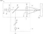
- FIG. 1is a schematic diagram of an optical probe for detecting a biological tissue, which is applied to an optical detecting system, according to an exemplary embodiment of the disclosure.
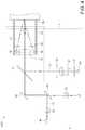
- FIG. 2is a schematic diagram of an optical probe for detecting a biological tissue according to an exemplary embodiment of the disclosure.
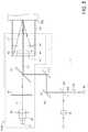
- FIG. 3is a schematic diagram of focal planes of a telecentric lens of an optical probe for detecting a biological tissue according to an exemplary embodiment of the disclosure.
- FIG. 4is a schematic diagram of an optical probe for detecting a biological tissue according to an exemplary embodiment of the disclosure.
- FIG. 5is a schematic diagram of an optical probe for detecting a biological tissue according to an exemplary embodiment of the disclosure.
- an optical probe for detecting a biological tissuemay capture a surface image and a tomography image of the biological tissue, and couple to an image process system to detect a skin layer and a deep layer status at the same time.
- an optical detecting system 200may be an optical coherence tomography (OCT) system.
- OCToptical coherence tomography
- an optical probe 1000 for detecting a biological tissuecouples to an optical fiber coupler 3000 .
- the optical fiber coupler 3000receives a light beam emitted from a broad band light source 4000 and separates the light beam to a sample beam and a reference beam.
- the optical probe 1000 for detecting the biological tissueis used as a sample arm of the OCT system and receives the sample beam from the optical fiber coupler 3000 .
- the sample beam reflected from the biological tissue and the reference beamcame from a reference arm 2000 form an interference signal, and the interference signal is analyzed and processed in a tomography analysis module 5000 to form a tomography image of the biological tissue.
- an optical probe 1000 for detecting a biological tissue 100includes a surface imaging module 1 capturing a surface image of the biological tissue 100 , wherein the surface imaging module 1 includes a telecentric lens 10 , a first optical mirror 20 , a lens assembly 30 , an imaging sensor 40 , and a light source 42 emitting a first detecting light L 1 ; and a tomography capturing module 2 , capturing a tomography image of the biological tissue 100 and receiving a second detecting light L 2 , wherein the tomography capturing module includes the telecentric lens 10 , the first optical mirror 20 , a scanner 50 , and a first collimator 60 , wherein the first detecting light L 1 passes via a first optical path from the light source 42 to the imaging sensor 40 through the biological tissue 100 , the telecentric lens 10 , the first optical mirror 20 , and the lens assembly 30 in sequence, and the second detecting light L 2 passes via a second optical path from the first collimator 60 to the
- a skin tissueis taken as an example, but the scope of the disclosure is not limited thereto.
- the surface imaging module 1 of the optical probe 1000 for detecting the biological tissue 100may capture a surface image of skin for determining tissue structures of a skin layer.
- the tomography capturing module 2 of the optical probe 1000 for detecting the biological tissue 100may capture a tomography image of skin for obtaining tissue structures of a deep layer.
- the surface imaging module 1 and the tomography capturing module 2share the telecentric lens 10 and the first optical mirror 20 , so the telecentric lens 10 and the first optical mirror 20 need to be carefully designed to make the surface imaging module 1 and the tomography capturing module 2 workable.
- a focal length of the telecentric lens 10ranges from 25 mm to 40 mm, and the biological tissue 100 is located on a front focal plane FFS of the telecentric lens 10 during the detecting process. If the focal length of the telecentric lens 10 is designed to be longer than the range of 25 mm to 40 mm, a request of a diameter of the lens assembly 30 will increase so that there are not enough space to dispose the lens assembly 30 in the optical probe 1000 for detecting the biological tissue 100 .
- a f-number (F/#) of the surface imaging module 1is too large so that the imaging sensor 40 is underexposed, and the optical probe 1000 for detecting the biological tissue 100 needs to dispose the light source 42 with higher light intensity, thereby resulting in power consumption.
- the focal length of the telecentric lens 10is shorter than the range of 25 mm to 40 mm, there are not enough space to dispose related elements.
- the focal length of the telecentric lens 10is longer than a focal length of the lens assembly 30 . More specifically, a ratio of the focal length of the telecentric lens 10 -to the focal length of the lens assembly 30 ranges from 1.4 to 2.8.
- the telecentric lens 10is disposed between the first optical mirror 20 and the biological tissue 100 .
- the lens assembly 30is disposed at one side of the first optical mirror 20 opposite to the telecentric lens 10 , and the lens assembly 30 is disposed between the imaging sensor 40 and the first optical mirror 20 .
- the first detecting light L 1 emitted from the light source 42radiates towards the biological tissue 100 , then the first detecting light L 1 scattered and reflected by the biological tissue 100 goes back to the telecentric lens 10 via the first light path, and enters the lens assembly 30 by the guiding of the first optical mirror 20 .
- the lens assembly 30may include at least two lens made from glass or plastic.
- the first detecting light L 1is focused by the lens assembly 30 and then passed to the imaging sensor 40 to form the surface image of the biological tissue 100 .
- the tomography capturing module 2is described.
- the scanner 50is disposed between the first optical mirror 20 and the first collimator 60 .
- the scanner 50is not disposed in a connection line of the telecentric lens 10 and the lens assembly 30 , but disposed in a projection position of the first optical mirror 20 .
- the second detecting light L 2 (sample beam) received by the tomography capturing module 2is collimated by the first collimator 60 , then enters the scanner 50 to scan via the second optical path.
- the first optical mirror 20guides the second detecting light L 2 to the telecentric lens 10 and the biological tissue 100 .
- the second detecting light L 2 reflected by the biological tissue 100enters the scanner 50 and the first collimator 60 , from the telecentric lens 10 through the first optical mirror 20 .
- the optical fiber coupler 3000 coupled to the tomography capturing module 2receives the second detecting light L 2 and the reference beam passed from the reference arm 2000 and forms the interference signal.
- the interference signalis sent to the tomography analysis module 5000 to analysis and process, and then form the tomography image of the biological tissue 100 .
- the first optical mirror 20guides the first detecting light L 1 and the second detecting light L 2 .
- the first optical mirror 20may be a dichroic mirror to allow an incident light with a specific wavelength range passing through, and to reflect another incident light with other wavelength ranges.
- the first optical mirror 20may have the first detecting light L 1 penetrating and may have the second detecting light L 2 being reflected.
- the first optical mirror 20can may be designed to allow a light with a wavelength ranging from 300 nm to 700 nm passing through, and to allow a light with a wavelength ranging from 700 nm to 900 nm being reflected. Therefore, the wavelength corresponding to the first detecting light L 1 will range from 300 nm to 700 nm, and the wavelength corresponding to the second detecting light L 2 will range from 700 nm to 900 nm.
- the first optical mirror 20may reflect the first detecting light L 1 and may be penetrated by the second detecting light L 2 .
- the scanner 50is disposed at one side of the first optical mirror 20 opposite to the telecentric lens 10
- the lens assembly 30is disposed in the projection position of the first optical mirror 20 .
- the first optical mirror 20can be designed to allow a light with a wavelength ranging from 700 nm to 900 nm passing through, and reflect a light with a wavelength ranging from 300 nm to 700 nm. Therefore, the wavelength corresponding to the first detecting light L 1 will range from 300 nm to 700 nm, and the wavelength corresponding to the second detecting light L 2 will range from 700 nm to 900 nm.
- the first optical mirror 20may be fixed or movable. If the first optical mirror 20 is fixed, the optical probe 1000 for detecting the biological tissue 100 may capture the surface image and the tomography image at the same time. However, if the first optical mirror 20 is movable, the optical probe 1000 for detecting the biological tissue 100 may capture the surface image and the tomography image individually or in company. In the embodiment of FIG. 2 , when the movable first optical mirror 20 is removed, the surface imaging module 1 may capture the surface image alone, while in the embodiment of FIG. 4 , when the movable first optical mirror 20 is removed, the tomography capturing module 2 may capture the tomography image alone.
- the optical probe 1000 for detecting a biological tissue 100further comprises an aperture 32 .
- the aperture 32is disposed between the telecentric lens 10 and the lens assembly 30 , and located in a position less than 0.56 times of a back focal length BFL of the telecentric lens 10 from the back focal plane BFS of the telecentric lens 10 to the biological tissue 100 .
- the aperture 32is disposed between the surface S and the back focal length BFL of the telecentric lens 10 . Therefore, it may increase a resolution of the optical probe 1000 for detecting a biological tissue 100 , decrease a volume of the surface imaging module 1 , and provide good efficiency of light collection. It is noted that the position of the aperture 32 needs to be carefully designed.
- the aperture 32may be combined and disposed inside the lens assembly 30 . In the embodiment of FIG. 3 , the aperture 32 may be disposed between the first optical mirror 20 and the lens assembly 30 .
- a f-number of the surface imaging module 1 near the imaging sensor 40ranges from 2 to 5. If the f-number is more than the range from 2 to 5, the request of the diameter of the lens assembly 30 will increase. This will not facilitate the reduction of the optical probe 1000 for detecting the biological tissue 100 . Moreover, it may cause the imaging sensor 40 to underexpose. When the f-number is less than the range from 2 to 5, an aberration between the telecentric lens 10 and the lens assembly 30 will increase, and this also increase the complexity of overall optical structures. In addition, a size of the imaging sensor 40 is smaller than a field of vision (FOV) of the surface imaging module 1 .
- FOVfield of vision
- the light source 42is disposed around the telecentric lens 10 , to have the first detecting light L 1 being emitted to the biological tissue 100 , and then transmitted to the imaging sensor 40 via the first optical path.
- the optical probe 1000 for detecting the biological tissue 100further comprises a first polarizer 34 and a second polarizer 36 .
- the first polarizer 34has a hollow ring shape and is disposed between the light source 42 and the biological tissue 100 without covering the second optical path, and the second polarizer 36 is disposed between the telecentric lens 10 and the imaging sensor 40 . It is noted that the second polarizer 36 may be set in any place between the telecentric lens 10 and the imaging sensor 40 .
- the second polarizer 36is disposed between the lens assembly 30 and the imaging sensor 40 .
- the second polarizer 36is disposed between the lens assembly 30 and the first optical mirror 20 , but the scope of the disclosure is not limited thereto.
- the first polarizer 34 and the second polarizer 36may decrease a reflection of the biological tissue 100 .
- optical axes of the first polarizer 34 and the second polarizer 36may be vertical or caused an angle. As long as polarization directions of the first polarizer 34 and the second polarizer 36 are different, the first polarizer 34 and the second polarizer 36 is workable in this case, but the scope of the disclosure is not limited thereto.
- the light source 42may be an LED, a color adjustable LED, or an UV LED to detect different type of states of the biological tissue 100 .
- textures and freckles of the skincan be observed by using different wavelengths of the light source 42
- a stimulated fluorescence of bacteria on the surface of the skincan be observed by using UV LED as the light source 42 .
- the optical probe 1000 for detecting the biological tissue 100detects in company with the first polarizer 34 and the second polarizer 36 , if a parallel polarized light is produced, it may increase a contrast ratio of the textures of the skin surface, and if a cross polarized light is produced, it may obtain distributions of blood vessels and melanin beneath the skin surface.
- a field of vision of the tomography capturing module 2ranges from 2 to 5 mm to observe larger ranges of the biological tissue 100 .
- the field of vision of the tomography capturing module 2may equal to the field of vision of the surface imaging module 1 to detect the surface condition and the deep structure at the same location.
- the same field of vision of the surface imaging module 1 and the tomography capturing module 2may detect the surface condition and the deep structure of skin at the same location.
- a f-number of the tomography capturing module 2 near the biological tissue 100ranges from 5.8 to 8.75. It is noted that if the f-number is greater than the range from 5.8 to 8.75, it may cause an insufficient horizontal resolution of the biological tissue 100 , and if the f-number is less than the range from 5.8 to 8.75, it may increase the aberration of the telecentric lens 10 so as to increase the complexity of overall optical structures and will not facilitate the reduction of the optical probe 1000 for detecting the biological tissue 100 .
- the scanner 50may transform the second detecting light L 2 with single angle to a multi-angle collimated light beam.
- the scanner 50may include one or more scan mirrors to perform a scanning process, wherein the scan mirror is a Galvo mirror. Please refer to FIG. 2 and FIG. 4 .
- the scanner 50includes a scan mirror located on the back focal plane BFS of the telecentric lens 10 to perform a linear scanning process.
- the scanner 50includes a first scan mirror 52 and a second mirror 54 , the position of the back focal plane BFS of the telecentric lens 10 is located between the first scan mirror 52 and the second mirror 54 , and the first scan mirror 52 and the second mirror 54 may perform a plane scanning process.
- the first collimator 60may collimate the second detecting light L 2 emitted from the optical fiber coupler 3000 to incident to the scanner 50 .
- the optical probe 1000 for detecting the biological tissue 100further comprises a second collimator 62 , a second optical mirror 80 and a scanning indicating light 46 .
- the second collimator 62collimates a scanning indicating light beam L 3 emitted from the scanning indicating light 46
- the second optical mirror 80guides the second detecting light L 2 and the scanning indicating light beam L 3 which are collimated to pass via the second optical path and a third optical path, respectively.
- the scanning indicating light beam L 3passes via the third optical path to the biological tissue 100 through the second collimator 62 , the second optical mirror 80 , the scanner 50 , the first optical mirror 20 , and the telecentric lens 10 .
- the second detecting light L 2 received by the tomography capturing module 2is an invisible light, so an user cannot directly know the status that the second detecting light L 2 irradiates the biological tissue 100 . Therefore, by using the scanning indicating light beam L 3 as an auxiliary light to indicate a scan position, a capturing position of the biological tissue 100 can be confirmed.
- the scanning indicating light 46is a red laser, but the scope of the disclosure is not limited thereto.
- the second optical path which the second detecting light L 2 passes throughalmost coincide with the third optical path which the scanning indicating light beam L 3 passes through, so that if a red light of the scanning indicating light beam L 3 irradiates a position of the biological tissue 100 , the position of the biological tissue 100 will be regarded as a position that the second detecting light L 2 irradiates.
- the second optical mirror 80guides the second detecting light L 2 and the scanning indicating light beam L 3 passing through.
- the second optical mirror 80may be a dichroic mirror to allow an incident light with a specific wavelength range passing through and reflect another incident light with other wavelength ranges.
- the second optical mirror 80can be penetrated by the second detecting light L 2 and reflect the scanning indicating light beam L 3 .
- the second optical mirror 80may be designed to allow a light with a wavelength range over 780 nm passing through, and reflect a light with a wavelength ranging under 700 nm.
- the second optical mirror 80may reflect the second detecting light L 2 and be penetrated by the scanning indicating light beam L 3 .
- the second optical mirror 80can be designed to allow a light with a wavelength range under 700 nm passing through, and reflect a light with a wavelength range over 780 nm.
- the light with the wavelength ranging from 800 nm to 900 nmis used as the second detecting light L 2 and the light with the wavelength ranging from 620 nm to 700 nm is used as the scanning indicating light beam L 3 .
- the scanning indicating light beam L 3also passes through the first optical mirror 20 , so it may be designed that a wavelength in 50% transmittance of the first optical mirror 20 is within a range of a central wavelength of the scanning indicating light beam L 3 .
- the red laseris used as the scanning indicating light 46
- the range of the central wavelength of the red laseris about 620 nm to 700 nm, so it may choose a material that the wavelength in 50% transmittance is within the range from 620 nm to 700 nm to make the first optical mirror 20 .
- the optical probe 1000 for detecting the biological tissue 100further comprises a transparent cover 90 , wherein the transparent cover 90 connects to the telecentric lens 10 and a length L of the transparent cover is equal to the front focal length FFL of the telecentric lens 10 to make sure that the biological tissue 100 is fixed on the front focal plane FFS of the telecentric lens 10 and avoid defocusing that causes blurred images.
- the optical probe for detecting the biological tissue in the disclosuremay have that two different optical paths are in a single probe being realized, so that the optical probe for detecting the biological tissue may detect the skin layer and the deep layer status at the same time.
Landscapes
- Health & Medical Sciences (AREA)
- Life Sciences & Earth Sciences (AREA)
- Physics & Mathematics (AREA)
- Molecular Biology (AREA)
- Animal Behavior & Ethology (AREA)
- Pathology (AREA)
- Engineering & Computer Science (AREA)
- Biomedical Technology (AREA)
- Heart & Thoracic Surgery (AREA)
- Medical Informatics (AREA)
- Veterinary Medicine (AREA)
- Surgery (AREA)
- Biophysics (AREA)
- General Health & Medical Sciences (AREA)
- Public Health (AREA)
- Nuclear Medicine, Radiotherapy & Molecular Imaging (AREA)
- Radiology & Medical Imaging (AREA)
- Dermatology (AREA)
- Spectroscopy & Molecular Physics (AREA)
- Investigating Or Analysing Materials By Optical Means (AREA)
Abstract
Description
Claims (18)
Priority Applications (1)
| Application Number | Priority Date | Filing Date | Title |
|---|---|---|---|
| US15/717,116US11026581B2 (en) | 2016-09-30 | 2017-09-27 | Optical probe for detecting biological tissue |
Applications Claiming Priority (4)
| Application Number | Priority Date | Filing Date | Title |
|---|---|---|---|
| US201662401947P | 2016-09-30 | 2016-09-30 | |
| TW106131131 | 2017-09-12 | ||
| TW106131131ATWI652467B (en) | 2016-09-30 | 2017-09-12 | Optical probe for detecting biological tissue |
| US15/717,116US11026581B2 (en) | 2016-09-30 | 2017-09-27 | Optical probe for detecting biological tissue |
Publications (2)
| Publication Number | Publication Date |
|---|---|
| US20180092539A1 US20180092539A1 (en) | 2018-04-05 |
| US11026581B2true US11026581B2 (en) | 2021-06-08 |
Family
ID=61757439
Family Applications (1)
| Application Number | Title | Priority Date | Filing Date |
|---|---|---|---|
| US15/717,116Active2039-01-19US11026581B2 (en) | 2016-09-30 | 2017-09-27 | Optical probe for detecting biological tissue |
Country Status (2)
| Country | Link |
|---|---|
| US (1) | US11026581B2 (en) |
| CN (1) | CN107874741B (en) |
Families Citing this family (2)
| Publication number | Priority date | Publication date | Assignee | Title |
|---|---|---|---|---|
| CN109091107B (en)* | 2018-05-30 | 2021-09-24 | 深圳市斯尔顿科技有限公司 | Optical scanning method, device, equipment and computer storage medium |
| CN112274110B (en)* | 2020-10-10 | 2023-06-16 | 苏州万微光电科技有限公司 | Pore detection system, device and method based on skin fluorescence image |
Citations (31)
| Publication number | Priority date | Publication date | Assignee | Title |
|---|---|---|---|---|
| US5788639A (en) | 1995-07-13 | 1998-08-04 | Lucid Technologies, Inc. | Confocal imaging through thick dermal tissue |
| WO2002059643A2 (en) | 2001-01-25 | 2002-08-01 | Oti Ophthalmic Technologies Inc. | Spiral scanner with electronic control |
| US20060063986A1 (en) | 2004-08-19 | 2006-03-23 | Hogan Josh N | Concurrent scanning non-invasive analysis system |
| US20060119858A1 (en)* | 2004-12-02 | 2006-06-08 | Knighton Robert W | Enhanced optical coherence tomography for anatomical mapping |
| CN1911158A (en) | 2005-08-10 | 2007-02-14 | 安华高科技Ecbuip(新加坡)私人有限公司 | Imaging subcutaneous tissue |
| US20070263226A1 (en)* | 2006-05-15 | 2007-11-15 | Eastman Kodak Company | Tissue imaging system |
| CN101652784A (en) | 2007-03-02 | 2010-02-17 | 宝洁公司 | Method and apparatus for simulation of facial skin aging and de-aging |
| US20100321700A1 (en) | 2008-05-08 | 2010-12-23 | Canon Kabushiki Kaisha | Optical coherence tomographic imaging apparatus and optical coherence tomographic imaging method |
| US7859682B2 (en) | 2004-11-18 | 2010-12-28 | Michelson Diagnostics Limited | Optical interference apparatus |
| US7918791B2 (en) | 2008-11-19 | 2011-04-05 | Industrial Technology Research Institute | Optical scanning probe |
| TWI342201B (en) | 2007-08-03 | 2011-05-21 | Univ Minghsin Sci & Tech | |
| US20110164220A1 (en)* | 2006-01-20 | 2011-07-07 | Clarity Medical Systems, Inc. | Adaptive Sequential Wavefront Sensor with Variable Aperture |
| US20110206254A1 (en)* | 2010-02-22 | 2011-08-25 | Canfield Scientific, Incorporated | Reflectance imaging and analysis for evaluating tissue pigmentation |
| US20110273757A1 (en)* | 2009-01-30 | 2011-11-10 | Kowa Company Ltd. | Optical image-capturing apparatus |
| US20120188538A1 (en)* | 2011-01-24 | 2012-07-26 | Vanderbilt University | Common detector for combined raman spectroscopy-optical coherence tomography |
| CN102670177A (en) | 2011-03-15 | 2012-09-19 | 明达医学科技股份有限公司 | Skin optical diagnosis device and operation method thereof |
| US20120281071A1 (en)* | 2011-03-23 | 2012-11-08 | 3Dm Systems, Inc. | Optical Scanning Device |
| TWI385598B (en) | 2009-12-01 | 2013-02-11 | Ind Tech Res Inst | Image processing method, training method of classifier and evaluate method of lesion risk |
| CN103181746A (en) | 2011-12-30 | 2013-07-03 | 上海市第七人民医院 | Portable endoscope display |
| US20130169931A1 (en) | 2011-12-29 | 2013-07-04 | Industrial Technology Research Institute | Auto-focusing diagnostic equipment |
| US20130182096A1 (en) | 2010-09-17 | 2013-07-18 | Lltech Management | Optical tissue sectioning using full field optical coherence tomography |
| US20130242311A1 (en)* | 2012-03-16 | 2013-09-19 | Mitutoyo Corporation | White-light interferometric measuring device |
| US20140218740A1 (en) | 2011-04-06 | 2014-08-07 | Agfa Healthcare Nv | Method and System for Optical Coherence Tomography |
| US8873034B2 (en) | 2012-12-19 | 2014-10-28 | China Medical University | Fiber-type image capturing method and apparatus thereof |
| US20150043003A1 (en)* | 2012-04-18 | 2015-02-12 | Lg Electronics Inc. | Optical coherence tomography and control method for the same |
| CN104352216A (en) | 2014-10-13 | 2015-02-18 | 佛山市南海区欧谱曼迪科技有限责任公司 | Endoscope irradiation spectrum selection device and hyperspectral endoscope imaging system |
| CN204694910U (en) | 2015-04-17 | 2015-10-07 | 中国人民解放军空军总医院 | A kind of dermoscopy 50X polarization optics camera lens |
| TWI513450B (en) | 2013-08-06 | 2015-12-21 | ||
| CN105725979A (en) | 2016-05-16 | 2016-07-06 | 王军 | Human body moire imaging device |
| US20170193659A1 (en) | 2016-01-05 | 2017-07-06 | Industrial Technology Research Institute | Method for evaluating skin tissue and system using the same |
| CN107037016A (en) | 2016-02-04 | 2017-08-11 | 北京世纪桑尼科技有限公司 | A kind of confocal optical scanner |
- 2017
- 2017-09-27USUS15/717,116patent/US11026581B2/enactiveActive
- 2017-09-28CNCN201710897817.7Apatent/CN107874741B/enactiveActive
Patent Citations (33)
| Publication number | Priority date | Publication date | Assignee | Title |
|---|---|---|---|---|
| US5788639A (en) | 1995-07-13 | 1998-08-04 | Lucid Technologies, Inc. | Confocal imaging through thick dermal tissue |
| WO2002059643A2 (en) | 2001-01-25 | 2002-08-01 | Oti Ophthalmic Technologies Inc. | Spiral scanner with electronic control |
| US20060063986A1 (en) | 2004-08-19 | 2006-03-23 | Hogan Josh N | Concurrent scanning non-invasive analysis system |
| US7859682B2 (en) | 2004-11-18 | 2010-12-28 | Michelson Diagnostics Limited | Optical interference apparatus |
| US20060119858A1 (en)* | 2004-12-02 | 2006-06-08 | Knighton Robert W | Enhanced optical coherence tomography for anatomical mapping |
| CN1911158A (en) | 2005-08-10 | 2007-02-14 | 安华高科技Ecbuip(新加坡)私人有限公司 | Imaging subcutaneous tissue |
| US20110164220A1 (en)* | 2006-01-20 | 2011-07-07 | Clarity Medical Systems, Inc. | Adaptive Sequential Wavefront Sensor with Variable Aperture |
| US7460248B2 (en) | 2006-05-15 | 2008-12-02 | Carestream Health, Inc. | Tissue imaging system |
| US20070263226A1 (en)* | 2006-05-15 | 2007-11-15 | Eastman Kodak Company | Tissue imaging system |
| CN101652784A (en) | 2007-03-02 | 2010-02-17 | 宝洁公司 | Method and apparatus for simulation of facial skin aging and de-aging |
| TWI342201B (en) | 2007-08-03 | 2011-05-21 | Univ Minghsin Sci & Tech | |
| US20100321700A1 (en) | 2008-05-08 | 2010-12-23 | Canon Kabushiki Kaisha | Optical coherence tomographic imaging apparatus and optical coherence tomographic imaging method |
| US7918791B2 (en) | 2008-11-19 | 2011-04-05 | Industrial Technology Research Institute | Optical scanning probe |
| US20110273757A1 (en)* | 2009-01-30 | 2011-11-10 | Kowa Company Ltd. | Optical image-capturing apparatus |
| TWI385598B (en) | 2009-12-01 | 2013-02-11 | Ind Tech Res Inst | Image processing method, training method of classifier and evaluate method of lesion risk |
| US20110206254A1 (en)* | 2010-02-22 | 2011-08-25 | Canfield Scientific, Incorporated | Reflectance imaging and analysis for evaluating tissue pigmentation |
| US20130182096A1 (en) | 2010-09-17 | 2013-07-18 | Lltech Management | Optical tissue sectioning using full field optical coherence tomography |
| US20120188538A1 (en)* | 2011-01-24 | 2012-07-26 | Vanderbilt University | Common detector for combined raman spectroscopy-optical coherence tomography |
| CN102670177A (en) | 2011-03-15 | 2012-09-19 | 明达医学科技股份有限公司 | Skin optical diagnosis device and operation method thereof |
| TWI519277B (en) | 2011-03-15 | 2016-02-01 | 明達醫學科技股份有限公司 | Skin optical diagnosing apparatus and operating method thereof |
| US20120281071A1 (en)* | 2011-03-23 | 2012-11-08 | 3Dm Systems, Inc. | Optical Scanning Device |
| US20140218740A1 (en) | 2011-04-06 | 2014-08-07 | Agfa Healthcare Nv | Method and System for Optical Coherence Tomography |
| US20130169931A1 (en) | 2011-12-29 | 2013-07-04 | Industrial Technology Research Institute | Auto-focusing diagnostic equipment |
| CN103181746A (en) | 2011-12-30 | 2013-07-03 | 上海市第七人民医院 | Portable endoscope display |
| US20130242311A1 (en)* | 2012-03-16 | 2013-09-19 | Mitutoyo Corporation | White-light interferometric measuring device |
| US20150043003A1 (en)* | 2012-04-18 | 2015-02-12 | Lg Electronics Inc. | Optical coherence tomography and control method for the same |
| US8873034B2 (en) | 2012-12-19 | 2014-10-28 | China Medical University | Fiber-type image capturing method and apparatus thereof |
| TWI513450B (en) | 2013-08-06 | 2015-12-21 | ||
| CN104352216A (en) | 2014-10-13 | 2015-02-18 | 佛山市南海区欧谱曼迪科技有限责任公司 | Endoscope irradiation spectrum selection device and hyperspectral endoscope imaging system |
| CN204694910U (en) | 2015-04-17 | 2015-10-07 | 中国人民解放军空军总医院 | A kind of dermoscopy 50X polarization optics camera lens |
| US20170193659A1 (en) | 2016-01-05 | 2017-07-06 | Industrial Technology Research Institute | Method for evaluating skin tissue and system using the same |
| CN107037016A (en) | 2016-02-04 | 2017-08-11 | 北京世纪桑尼科技有限公司 | A kind of confocal optical scanner |
| CN105725979A (en) | 2016-05-16 | 2016-07-06 | 王军 | Human body moire imaging device |
Non-Patent Citations (11)
| Title |
|---|
| Alex Zlotnik, et al., "Improved extended depth of focus full field spectral domain Optical Coherence Tomography", Optics Communications, 2010, vol. 283, Iss. 24, pp. 4963-4968. |
| Arnaud Dubois, et al., "High-resolution full-field optical coherence tomography with a Linnik microscope", Applied Optics, Feb. 1, 2002, vol. 41, No. 4, pp. 805-812. |
| Boris Pova{hacek over (z)}ay, et al., "Full-field time-encoded frequency-domain optical coherence tomography", Optics Express, Aug. 21, 2006, vol. 14, No. 17, pp. 7661-7669. |
| Chien-Chung Tsai, et al., "Full-depth epidermis tomography using a Mirau-based full-field optical coherence Tomography", Biomedical Optics Express, Sep. 1, 2014, vol. 5, No. 9, pp. 3001-3010. |
| J. Kraute, et al., "Optical design of a Vertically Integrated Array-type Mirau-based OCT System", Proc. of SPIE, 2014, vol. 9132, pp. 91320L-1-91320L-7. |
| Joseph A. Izatt, et al., "Optical coherence microscopy in scattering media", Optics Letters, vol. 19, No. 8, Apr. 15, 1994, pp. 590-592. |
| M. Wojtkowski, et al., "Full range complex spectral optical coherence tomography technique in eye imaging", Optics Letters, Aug. 15, 2002, vol. 27, No. 16, pp. 1415-1417. |
| Maciej Wojtkowski, et al., "In vivo human retinal imaging by Fourier domain optical coherence tomography", Journal of Biomedical Optics, Jul. 2002, vol. 7, No. 3, pp. 457-463. |
| Seungwan Lee, et al., "Optical probe design with extended depth-of-focus for optical coherence microscopy and optical coherence tomography", Proc. of SPIE, 2013, vol. 8616, pp. 861604-1-861604-8. |
| Taniguchi, K. "A tutorial for designing fundamental imaging systems." University of Arizona OPTI 521 Tutorial. Nov. 2009.* |
| Yong Huang, et al., "Motion-compensated hand-held common-path Fourier-domain optical coherence tomography probe for image-guided intervention", Biomedical Optics Express , Dec. 1, 2012, vol. 3, No. 12, pp. 3105-3118. |
Also Published As
| Publication number | Publication date |
|---|---|
| CN107874741B (en) | 2023-01-24 |
| CN107874741A (en) | 2018-04-06 |
| US20180092539A1 (en) | 2018-04-05 |
Similar Documents
| Publication | Publication Date | Title |
|---|---|---|
| US10667694B2 (en) | Apparatus for imaging skin | |
| US10156434B2 (en) | Optical coherence tomography imaging systems and methods | |
| US9072460B2 (en) | Optical coherence tomography device and optical coherence tomography method | |
| US20180008143A1 (en) | Optical coherence tomography system and method with multiple apertures | |
| US20060135861A1 (en) | Apparatus and method for blood analysis | |
| US8447079B2 (en) | Linearly polarized light imaging method and device | |
| US11737673B1 (en) | Systems for detecting carious lesions in teeth using short-wave infrared light | |
| CN105877711A (en) | Multimode imaging detection system for skin disease | |
| CN205758513U (en) | A kind of dermatosis multi-modality imaging detecting system | |
| CN103048294A (en) | Integrated multi-mode imaging method fusing ultrasonic imaging, photoacoustic imaging and optical coherence tomography and system employing same | |
| JP2017176811A5 (en) | ||
| JP2019200404A (en) | Optical module and optical device | |
| US11026581B2 (en) | Optical probe for detecting biological tissue | |
| JP7389487B2 (en) | Interferometric imaging device and its applications | |
| Li et al. | Low-cost high-resolution photoacoustic microscopy of blood oxygenation with two laser diodes | |
| JP6474148B2 (en) | Inspection device | |
| US20080045817A1 (en) | Apparatus and Method for Performing Othogonal Polarized Spectral Imaging (Opsi) | |
| US8406835B2 (en) | Probe head for spectroscopic analysis of a fluid | |
| CN218572188U (en) | Laser speckle blood flow imaging system | |
| KR102028041B1 (en) | Apparatus and method for optical image based on convergence of multiple optical images | |
| TWI652467B (en) | Optical probe for detecting biological tissue | |
| CN206687691U (en) | A kind of reflective confocal microscopic image system | |
| US20240126058A1 (en) | Methods and apparatus for high-resolution microscopy | |
| CN110477852B (en) | Iris vascular imaging system | |
| JP2021065366A (en) | Inspection device and inspection module |
Legal Events
| Date | Code | Title | Description |
|---|---|---|---|
| FEPP | Fee payment procedure | Free format text:ENTITY STATUS SET TO UNDISCOUNTED (ORIGINAL EVENT CODE: BIG.); ENTITY STATUS OF PATENT OWNER: LARGE ENTITY | |
| AS | Assignment | Owner name:INDUSTRIAL TECHNOLOGY RESEARCH INSTITUTE, TAIWAN Free format text:ASSIGNMENT OF ASSIGNORS INTEREST;ASSIGNORS:WANG, CHY-LIN;LEE, YUAN-CHIN;HUANG, CHUN-CHIEH;AND OTHERS;SIGNING DATES FROM 20170930 TO 20171003;REEL/FRAME:044072/0553 | |
| STPP | Information on status: patent application and granting procedure in general | Free format text:DOCKETED NEW CASE - READY FOR EXAMINATION | |
| STPP | Information on status: patent application and granting procedure in general | Free format text:NON FINAL ACTION MAILED | |
| STPP | Information on status: patent application and granting procedure in general | Free format text:RESPONSE TO NON-FINAL OFFICE ACTION ENTERED AND FORWARDED TO EXAMINER | |
| STPP | Information on status: patent application and granting procedure in general | Free format text:NOTICE OF ALLOWANCE MAILED -- APPLICATION RECEIVED IN OFFICE OF PUBLICATIONS | |
| STPP | Information on status: patent application and granting procedure in general | Free format text:PUBLICATIONS -- ISSUE FEE PAYMENT RECEIVED | |
| STPP | Information on status: patent application and granting procedure in general | Free format text:PUBLICATIONS -- ISSUE FEE PAYMENT VERIFIED | |
| STCF | Information on status: patent grant | Free format text:PATENTED CASE | |
| MAFP | Maintenance fee payment | Free format text:PAYMENT OF MAINTENANCE FEE, 4TH YEAR, LARGE ENTITY (ORIGINAL EVENT CODE: M1551); ENTITY STATUS OF PATENT OWNER: LARGE ENTITY Year of fee payment:4 |