US11026346B2 - Water-replenishing and gas-removing structure for water cooling device - Google Patents
Water-replenishing and gas-removing structure for water cooling deviceDownload PDFInfo
- Publication number
- US11026346B2 US11026346B2US15/959,296US201815959296AUS11026346B2US 11026346 B2US11026346 B2US 11026346B2US 201815959296 AUS201815959296 AUS 201815959296AUS 11026346 B2US11026346 B2US 11026346B2
- Authority
- US
- United States
- Prior art keywords
- opening
- water
- connecting member
- chamber
- main body
- Prior art date
- Legal status (The legal status is an assumption and is not a legal conclusion. Google has not performed a legal analysis and makes no representation as to the accuracy of the status listed.)
- Active, expires
Links
Images


Classifications
- H—ELECTRICITY
- H05—ELECTRIC TECHNIQUES NOT OTHERWISE PROVIDED FOR
- H05K—PRINTED CIRCUITS; CASINGS OR CONSTRUCTIONAL DETAILS OF ELECTRIC APPARATUS; MANUFACTURE OF ASSEMBLAGES OF ELECTRICAL COMPONENTS
- H05K7/00—Constructional details common to different types of electric apparatus
- H05K7/20—Modifications to facilitate cooling, ventilating, or heating
- H05K7/20218—Modifications to facilitate cooling, ventilating, or heating using a liquid coolant without phase change in electronic enclosures
- H05K7/20272—Accessories for moving fluid, for expanding fluid, for connecting fluid conduits, for distributing fluid, for removing gas or for preventing leakage, e.g. pumps, tanks or manifolds
- F—MECHANICAL ENGINEERING; LIGHTING; HEATING; WEAPONS; BLASTING
- F28—HEAT EXCHANGE IN GENERAL
- F28D—HEAT-EXCHANGE APPARATUS, NOT PROVIDED FOR IN ANOTHER SUBCLASS, IN WHICH THE HEAT-EXCHANGE MEDIA DO NOT COME INTO DIRECT CONTACT
- F28D15/00—Heat-exchange apparatus with the intermediate heat-transfer medium in closed tubes passing into or through the conduit walls ; Heat-exchange apparatus employing intermediate heat-transfer medium or bodies
- G—PHYSICS
- G06—COMPUTING OR CALCULATING; COUNTING
- G06F—ELECTRIC DIGITAL DATA PROCESSING
- G06F1/00—Details not covered by groups G06F3/00 - G06F13/00 and G06F21/00
- G06F1/16—Constructional details or arrangements
- G06F1/20—Cooling means
- G06F1/203—Cooling means for portable computers, e.g. for laptops
- H—ELECTRICITY
- H05—ELECTRIC TECHNIQUES NOT OTHERWISE PROVIDED FOR
- H05K—PRINTED CIRCUITS; CASINGS OR CONSTRUCTIONAL DETAILS OF ELECTRIC APPARATUS; MANUFACTURE OF ASSEMBLAGES OF ELECTRICAL COMPONENTS
- H05K7/00—Constructional details common to different types of electric apparatus
- H05K7/20—Modifications to facilitate cooling, ventilating, or heating
- H05K7/20218—Modifications to facilitate cooling, ventilating, or heating using a liquid coolant without phase change in electronic enclosures
- H05K7/20281—Thermal management, e.g. liquid flow control
- H—ELECTRICITY
- H05—ELECTRIC TECHNIQUES NOT OTHERWISE PROVIDED FOR
- H05K—PRINTED CIRCUITS; CASINGS OR CONSTRUCTIONAL DETAILS OF ELECTRIC APPARATUS; MANUFACTURE OF ASSEMBLAGES OF ELECTRICAL COMPONENTS
- H05K7/00—Constructional details common to different types of electric apparatus
- H05K7/20—Modifications to facilitate cooling, ventilating, or heating
- H05K7/20709—Modifications to facilitate cooling, ventilating, or heating for server racks or cabinets; for data centers, e.g. 19-inch computer racks
- H05K7/20763—Liquid cooling without phase change
- F—MECHANICAL ENGINEERING; LIGHTING; HEATING; WEAPONS; BLASTING
- F28—HEAT EXCHANGE IN GENERAL
- F28D—HEAT-EXCHANGE APPARATUS, NOT PROVIDED FOR IN ANOTHER SUBCLASS, IN WHICH THE HEAT-EXCHANGE MEDIA DO NOT COME INTO DIRECT CONTACT
- F28D21/00—Heat-exchange apparatus not covered by any of the groups F28D1/00 - F28D20/00
- F28D2021/0019—Other heat exchangers for particular applications; Heat exchange systems not otherwise provided for
- F28D2021/0028—Other heat exchangers for particular applications; Heat exchange systems not otherwise provided for for cooling heat generating elements, e.g. for cooling electronic components or electric devices
- F28D2021/0031—Radiators for recooling a coolant of cooling systems
- F—MECHANICAL ENGINEERING; LIGHTING; HEATING; WEAPONS; BLASTING
- F28—HEAT EXCHANGE IN GENERAL
- F28F—DETAILS OF HEAT-EXCHANGE AND HEAT-TRANSFER APPARATUS, OF GENERAL APPLICATION
- F28F2250/00—Arrangements for modifying the flow of the heat exchange media, e.g. flow guiding means; Particular flow patterns
- F28F2250/08—Fluid driving means, e.g. pumps, fans
- F—MECHANICAL ENGINEERING; LIGHTING; HEATING; WEAPONS; BLASTING
- F28—HEAT EXCHANGE IN GENERAL
- F28F—DETAILS OF HEAT-EXCHANGE AND HEAT-TRANSFER APPARATUS, OF GENERAL APPLICATION
- F28F2265/00—Safety or protection arrangements; Arrangements for preventing malfunction
- F28F2265/18—Safety or protection arrangements; Arrangements for preventing malfunction for removing contaminants, e.g. for degassing
- G—PHYSICS
- G06—COMPUTING OR CALCULATING; COUNTING
- G06F—ELECTRIC DIGITAL DATA PROCESSING
- G06F2200/00—Indexing scheme relating to G06F1/04 - G06F1/32
- G06F2200/20—Indexing scheme relating to G06F1/20
- G06F2200/201—Cooling arrangements using cooling fluid
Definitions
- the present inventionrelates to a water-replenishing and gas-removing structure for water cooling device, and more particularly to a water-replenishing and gas-removing structure that allows cooling fluid to be replenished into and surplus gas to be removed from a water cooling device without the need of disassembling or reworking the water cooling device.
- a water cooling devicemainly includes a water block, a pump and a water-cooling radiator; and these units are serially connected to one another via pipes.
- the water blockis mainly used to absorb heat.
- the water blockincludes a water-receiving chamber having an open side, which is closed by a heat-exchange interface plate made of a material with good thermal conductivity.
- An outer side of the heat-exchange interface plate facing away from the water-receiving chamberis in direct contact with a heat source for absorbing heat produced by the heat source.
- the absorbed heatis then transferred from the outer side to an inner side of the heat-exchange interface plate, and the inner side has a plurality of heat radiating fins provided thereon.
- a cooling fluidsuch as pure water, ethanol or a coolant, is filled in the water-receiving chamber for cooling circulation. By way of heat exchange, the cooling fluid circulates through and cools the heat radiating fins that have absorbed heat, so as to accomplish the cooling operation.
- the cooling fluid having absorbed heat from the heat radiating finsis driven by a pump to flow from the water head to the water-cooling radiator, at which the heated cooling fluid is cooled. Finally, the cooled cooling fluid flows into the water head again to circulate through the heat radiating fins to cool the latter.
- the cooling fluidtends to leak from the device and air tends to permeate the device, which results in poor working efficiency of the water cooling device.
- the cooling fluid in the water cooling devicewill volatilize or leak after the water cooling device has been used for a long period of time, which will also results in poor working efficiency of the water cooling device.
- a primary object of the present inventionis to provide a water-replenishing and gas-removing structure for water cooling device, so that cooling fluid in a water cooling device can be replenished and surplus gas in the water cooling device can be removed without the need of disassembling or reworking the water cooling device.
- the water-replenishing and gas-removing structure for water cooling deviceincludes a flow-guiding main body, a first valve member, a second valve member, a first connecting member and a second connecting member.
- the flow-guiding main bodyhas at least an inlet, an outlet, a water-receiving space, a first opening and a second opening.
- the inlet, the outlet, the first opening and the second openingare communicable with the water-receiving space.
- the first valve memberis arranged in the water-receiving space corresponding to the first opening for opening or closing the first opening; and the second valve member is arranged in the water-receiving space corresponding to the second opening for opening or closing the second opening.
- the first connecting memberis correspondingly connected to the first opening, and the second connecting member is correspondingly connected to the second opening.
- cooling fluidcan be replenished into and surplus gas can be removed from a water cooling device without the need of disassembling or reworking the water cooling device, enabling the water cooling device to have largely prolonged service life and largely increased working efficiency.
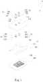
- FIG. 1is an exploded perspective view of a water-replenishing and gas-removing structure for water cooling device according to a first embodiment of the present invention
- FIG. 2is a cutaway view of the water-replenishing and gas-removing structure for water cooling device according to the first embodiment of the present invention
- FIG. 3shows the water-replenishing and gas-removing structure for water cooling device according to the first embodiment of the present invention in use
- FIG. 4is an exploded perspective view of a water-replenishing and gas-removing structure for water cooling device according to a second embodiment of the present invention
- FIG. 5is a cutaway view of the water-replenishing and gas-removing structure for water cooling device according to the second embodiment of the present invention.
- FIG. 6shows the water-replenishing and gas-removing structure for water cooling device according to the second embodiment of the present invention in use.
- FIGS. 1 and 2are exploded perspective view and cutaway view, respectively, of a water-replenishing and gas-removing structure for water cooling device according to a first embodiment of the present invention; and to FIG. 3 , which shows the water-replenishing and gas-removing structure for water cooling device of FIGS. 1 and 2 in use.
- the water-replenishing and gas-removing structure for water cooling device according to the present inventionis generally denoted by a reference numeral 1 and is herein briefly referred to as the water-replenishing and gas-removing structure 1 .
- the water-replenishing and gas-removing structure 1 in the first embodimentincludes a flow-guiding main body 11 , a first valve member 12 , a second valve member 13 , a first connecting member 14 , and a second connecting member 15 .
- the flow-guiding main body 11has at least an inlet 111 , an outlet 112 , a water-receiving space 113 , a first opening 114 and a second opening 115 .
- the inlet 111 , the outlet 112 , the first opening 114 and the second opening 115are communicable with the water-receiving space 113 .
- the flow-guiding main body 11is a water block.
- a cooling fluid 2flows into and leaves the water-receiving space 113 via the inlet 111 and the outlet 112 , respectively.
- the first and the second opening 114 , 115can be selectively formed on the flow-guiding main body 11 at any place thereof or at positions adjacent to the inlet 111 and the outlet 112 , respectively.
- the first valve member 12is arranged in the water-receiving space 113 corresponding to the first opening 114 for opening or closing the first opening 114 ; and the second valve member 13 is arranged in the water-receiving space 113 corresponding to the second opening 115 for opening or closing the second opening 115 .
- the first connecting member 14is correspondingly connected to the first opening 114 and the second connecting member 15 is correspondingly connected to the second opening 115 .
- the first connecting member 14has a first axial bore 141 axially extended through the first connecting member 14 , and a first radial connecting slot 142 radially extended through the first connecting member 14 and formed on an end of the first connecting member 14 that is to be connected to the first opening 114 .
- the first axial bore 141 and the first radial connecting slot 142are communicable with each other.
- the first valve member 12is composed of a first body 121 , a first elastic element 122 and a first valve seat 123 .
- the first valve body 121includes a first valve stem 1211 , which is extended from one side of the first valve body 121 for movably inserting into the first valve seat 123 .
- the first elastic element 122is fitted around the first valve stem 1211 with two ends of the first elastic element 122 separately pressed against outer peripheral areas of the first valve body 121 and the first valve seat 123 .
- the second valve member 13is composed of a second body 131 , a second elastic element 132 and a second valve seat 133 .
- the second valve body 131includes a second valve stem 1311 , which is extended from one side of the second valve body 131 for movably inserting into the second valve seat 133 .
- the second elastic element 132is fitted around the second valve stem 1311 with two ends of the second elastic element 132 separately pressed against outer peripheral areas of the second valve body 131 and the second valve seat 133 .
- the second connecting member 15has a second axial bore 151 axially extended through the second connecting member 15 , and a second radial connecting slot 152 radially extended through the second connecting member 15 and formed on an end of the second connecting member 15 that is to be connected to the second opening 115 .
- the second axial bore 151 and the second radial connecting slot 152are communicable with each other.
- the first and the second connecting member 14 , 15are mainly used to connect the water-replenishing and gas-removing structure 1 to an external water-replenishing apparatus and an external gas-removing apparatus, respectively.
- the first and the second connecting member 14 , 15are connected to the first and the second opening 114 , 115 , respectively, to communicate with the water-receiving space 113 of the flow-guiding main body 11 , the first and the second connecting member 14 , 15 push the first and the second valve member 12 , 13 downward to thereby compress the first and the second elastic element 122 , 132 .
- the first and the second valve member 12 , 13can no longer close the first and the second opening 114 , 115 , such that the first and the second opening 114 , 115 are in an open state.
- the water-receiving space 113not only communicates with the first and the second opening 114 , 115 , but also the first and the second axial bore 141 , 151 as well as the first and the second radial slot 142 , 152 of the first and the second connecting member 14 , 15 .
- the first connecting member 14is connected at another end, which is located opposite to the first opening 114 , to a first pipe 3 .
- the cooling fluid 2is supplied via the first pipe 3 and the first connecting member 14 into the water-receiving space 113 of the flow-guiding main body 11 .
- the second connecting member 15is connected at another end, which is located opposite to the second opening 115 , to a second pipe 4 . Surplus gas and surplus cooling fluid 2 in the water-receiving space 113 are guided out of the flow-guiding main body 11 via the second connecting member 15 and the second pipe 4 .
- the first and the second connecting member 14 , 15can be connected to the first and the second opening 114 , 115 by way of screwing, tight-fitting or snap-fitting.
- the first and second connecting members 14 , 15are connected to the first and second openings 114 , 115 by screwing.
- the first and the second connecting member 14 , 15are externally provided at the end to be connected to the first and the second opening 114 , 115 with male threads 143 , 153 , respectively, and the first and the second opening 114 , 115 are internally provided with females threads 144 , 154 , respectively.
- first and the second connecting member 14 , 15are connected to the first and the second opening 114 , 115 through engagement of the male threads 143 , 153 with the female threads 144 , 154 , respectively.
- first embodimentis only illustrative, and in other operable embodiments, the first and second connecting members 14 , 15 can be connected to the first and second openings 114 , 115 in other manners.
- the inlet 111 and the outlet 112 of the flow-guiding main body 11are connected to a pump 5 , and are further connected to a water-cooling radiator 6 via a third pipe 9 and a fourth pipe 10 , respectively.
- the pump 5drives the cooling fluid 2 to circulate through the water-replenishing and gas-removing structure 1 and the water-cooling radiator 6 , and the water-cooling radiator 6 is mainly used to cool the cooling fluid 2 that has absorbed heat.
- water-replenishing and gas-removing operationscan be performed via the first/second openings 114 , 115 , the first/second valve members 12 , 13 , and the first/second connecting members 14 , 15 , respectively.
- FIGS. 4 and 5are exploded perspective view and cutaway view, respectively, of a water-replenishing and gas-removing structure 1 according to a second embodiment of the present invention
- FIG. 6shows the water-replenishing and gas-removing structure 1 of FIGS. 4 and 5 in use.
- the water-replenishing and gas-removing structure 1 in the second embodimentis partially structurally similar to the first embodiment. Therefore, all structural components of the second embodiment which are the same as those of the first embodiment are not repeatedly described herein.
- the second embodimentis different from the first embodiment in having a flow-guiding main body 11 , of which the water-receiving space 113 is internally provided with a first chamber 1131 , a second chamber 1132 , a third chamber 1133 , a heat-exchange chamber 1134 , and a communicating opening 1135 .
- the inlet 111communicates with the first chamber 1131
- the third chamber 1133communicates with the heat-exchange chamber 1134 via the communicating opening 1135
- the outlet 112communicates with another side of the heat-exchange chamber 1134 opposite to the communicating opening 1135 .
- the flow-guiding main body 11has a first pump 7 and a second pump 8 connected thereto.
- the first pump 7has a first inlet 71 and a first outlet 72 ; and the second pump 8 has a second inlet 81 and a second outlet 82 .
- the first inlet 71communicates with the first chamber 1131 ;
- the second chamber 1132communicates with the first outlet 72 and the second inlet 81 ;
- the third chamber 1133communicates with the second outlet 82 and the communicating opening 1135 .
- the heat-exchange chamber 1134is internally provided with a heat-exchange interface 1136 .
- the first opening 114communicates with the second chamber 1132 and the first valve member 12 is correspondingly arranged in the second chamber 1132 ; the second opening 115 communicates with the third chamber 1133 and the second valve member 13 is correspondingly arranged in the third chamber 1133 ; and the inlet 111 and the outlet 112 are connected to a water-cooling radiator 6 .
- first and the second opening 114 , 115should be used to replenish cooling fluid or remove surplus gas; and the first and second openings 114 , 115 as well as the first and second valve members 12 , 13 can be correspondingly arranged on the flow-guiding main body 11 at any suitable positions.
- cooling fluidcan be replenished into and surplus gas can be removed from a water cooling device without the need of disassembling or reworking the water cooling device, enabling the water cooling device to have largely prolonged service life and increased working efficiency.
Landscapes
- Engineering & Computer Science (AREA)
- Physics & Mathematics (AREA)
- Microelectronics & Electronic Packaging (AREA)
- Thermal Sciences (AREA)
- General Engineering & Computer Science (AREA)
- Theoretical Computer Science (AREA)
- Computer Hardware Design (AREA)
- Human Computer Interaction (AREA)
- General Physics & Mathematics (AREA)
- Mechanical Engineering (AREA)
- Heat-Exchange Devices With Radiators And Conduit Assemblies (AREA)
Abstract
Description
Claims (9)
Priority Applications (1)
| Application Number | Priority Date | Filing Date | Title |
|---|---|---|---|
| US15/959,296US11026346B2 (en) | 2018-04-23 | 2018-04-23 | Water-replenishing and gas-removing structure for water cooling device |
Applications Claiming Priority (1)
| Application Number | Priority Date | Filing Date | Title |
|---|---|---|---|
| US15/959,296US11026346B2 (en) | 2018-04-23 | 2018-04-23 | Water-replenishing and gas-removing structure for water cooling device |
Publications (2)
| Publication Number | Publication Date |
|---|---|
| US20190327856A1 US20190327856A1 (en) | 2019-10-24 |
| US11026346B2true US11026346B2 (en) | 2021-06-01 |
Family
ID=68238456
Family Applications (1)
| Application Number | Title | Priority Date | Filing Date |
|---|---|---|---|
| US15/959,296Active2038-08-22US11026346B2 (en) | 2018-04-23 | 2018-04-23 | Water-replenishing and gas-removing structure for water cooling device |
Country Status (1)
| Country | Link |
|---|---|
| US (1) | US11026346B2 (en) |
Cited By (1)
| Publication number | Priority date | Publication date | Assignee | Title |
|---|---|---|---|---|
| US20240175646A1 (en)* | 2007-08-09 | 2024-05-30 | Coolit Systems Inc. | Fluid heat exchange systems |
Families Citing this family (3)
| Publication number | Priority date | Publication date | Assignee | Title |
|---|---|---|---|---|
| TWI709364B (en)* | 2020-02-24 | 2020-11-01 | 美商美國未來科技公司 | Adjusting device for computer water cooling |
| US12173965B2 (en)* | 2020-03-23 | 2024-12-24 | The Government Of The United States Of America, As Represented By The Secretary Of The Navy | Hybrid loop heat pipe with integrated magnetically levitating bearingless pump |
| US11175102B1 (en)* | 2021-04-15 | 2021-11-16 | Chilldyne, Inc. | Liquid-cooled cold plate |
Citations (35)
| Publication number | Priority date | Publication date | Assignee | Title |
|---|---|---|---|---|
| KR20020023387A (en) | 2002-01-22 | 2002-03-28 | 성이제 | Cooling system of computer central processing unit |
| US20050253465A1 (en)* | 2002-09-13 | 2005-11-17 | Aisin Aw Co., Ltd | Drive device |
| CN2910576Y (en) | 2006-04-28 | 2007-06-13 | 珠海天威技术开发有限公司 | Ink cartridge of ink-jet printer and its one-way valve |
| US20080053641A1 (en)* | 2006-08-31 | 2008-03-06 | Foxconn Technology Co., Ltd. | Miniature liquid cooling device having an integral pump |
| CN201064063Y (en) | 2007-04-05 | 2008-05-21 | 万在工业股份有限公司 | Heat radiator for video control card |
| US20080164011A1 (en) | 2007-01-09 | 2008-07-10 | Inventec Corporation | Liquid cooling type heat-dissipating device |
| US20080314559A1 (en)* | 2007-06-21 | 2008-12-25 | Hsu I-Ta | Heat exchange structure and heat dissipating apparatus having the same |
| US20120024499A1 (en) | 2010-07-30 | 2012-02-02 | Asia Vital Components Co., Ltd. | Loop type pressure-gradient-drien low-pressure thermosiphon device |
| US20120152498A1 (en)* | 2007-08-09 | 2012-06-21 | Coolit Systems Inc. | Fluid heat exchange systems |
| CN202516726U (en) | 2012-03-13 | 2012-11-07 | 卓品制造公司 | Novel manual switch for sprayer |
| US20120285663A1 (en)* | 2011-05-10 | 2012-11-15 | Chun-Ming Wu | Condensing device and thermal module using same |
| US20130037733A1 (en)* | 2011-08-12 | 2013-02-14 | Hsiu-Hsiung LIU | Quick release connector |
| US20130051108A1 (en)* | 2011-08-31 | 2013-02-28 | Kabushiki Kaisha Yaskawa Denki | Electronic component cooling unit and power converting device |
| US20130299139A1 (en)* | 2009-12-15 | 2013-11-14 | Stephen Mounioloux | Radiator with integrated pump for actively cooling electronic devices |
| US20140069614A1 (en)* | 2012-09-13 | 2014-03-13 | Asia Vital Components Co., Ltd. | Heat dissipaion device and thermal module using same |
| CN204187069U (en) | 2014-10-23 | 2015-03-04 | 讯凯国际股份有限公司 | Water replenishment structure, pump with the water replenishment structure, and liquid cooling heat dissipation device |
| US20150090915A1 (en)* | 2013-03-15 | 2015-04-02 | Colder Products Company | Low-Spill Coupling Assembly |
| TWM506917U (en) | 2015-03-06 | 2015-08-11 | Cooler Master Co Ltd | Pinch type double anti-reverse quick release joint structure and water supply device and water cooling system |
| TWM512124U (en) | 2015-06-23 | 2015-11-11 | Asia Vital Components Co Ltd | Butt type water cooling device |
| US20160160813A1 (en)* | 2013-07-02 | 2016-06-09 | Mahle Metal Leve S.A. | Heat exchanger for the feeding of fuel in an internal combustion engine |
| US20160309618A1 (en)* | 2015-04-17 | 2016-10-20 | Cooler Master Co., Ltd. | Liquid cooling heat dissipation structure and method of manufacturing the same |
| US20160338223A1 (en)* | 2015-05-11 | 2016-11-17 | Cooler Master Co., Ltd. | Electronic device and liquid cooling heat dissipation structure thereof |
| US20160348823A1 (en)* | 2015-05-25 | 2016-12-01 | Cooler Master Co., Ltd. | Electronic device and multifunction integrated connection head assembly structure thereof |
| CN205789940U (en) | 2016-05-24 | 2016-12-07 | 冠鼎科技有限公司 | Liquid-cooled heat sink |
| CN206212522U (en) | 2016-08-17 | 2017-05-31 | 奇鋐科技股份有限公司 | Cooling components |
| CN106774735A (en) | 2016-12-05 | 2017-05-31 | 王建 | A kind of portable computer liquid cooling heat radiation system |
| US20170235350A1 (en)* | 2016-02-15 | 2017-08-17 | Cooler Master Technology Inc. | Cooling apparatus |
| CN107436657A (en) | 2016-05-26 | 2017-12-05 | 刘小明 | PC terminals and its heat abstractor |
| US20170363362A1 (en)* | 2016-06-16 | 2017-12-21 | Asia Vital Components Co., Ltd. | Water-cooling device |
| CN207020624U (en) | 2017-08-01 | 2018-02-16 | 超众科技股份有限公司 | Water-cooled heat sink |
| US20180067506A1 (en)* | 2016-09-07 | 2018-03-08 | Hewlett Packard Enterprise Development Lp | Modules to power and control pumps |
| US20180269131A1 (en)* | 2017-03-20 | 2018-09-20 | Facebook, Inc. | Component cooling system |
| US10198046B2 (en)* | 2016-01-27 | 2019-02-05 | Cooler Master Co., Ltd. | Heat exchange module and serial pump thereof |
| US20190174653A1 (en)* | 2017-12-06 | 2019-06-06 | Auras Technology Co., Ltd. | Liquid-cooling heat dissipating module |
| US10405458B2 (en)* | 2016-03-07 | 2019-09-03 | Fujitsu Limited | Fitting assembly and electronic device |
- 2018
- 2018-04-23USUS15/959,296patent/US11026346B2/enactiveActive
Patent Citations (35)
| Publication number | Priority date | Publication date | Assignee | Title |
|---|---|---|---|---|
| KR20020023387A (en) | 2002-01-22 | 2002-03-28 | 성이제 | Cooling system of computer central processing unit |
| US20050253465A1 (en)* | 2002-09-13 | 2005-11-17 | Aisin Aw Co., Ltd | Drive device |
| CN2910576Y (en) | 2006-04-28 | 2007-06-13 | 珠海天威技术开发有限公司 | Ink cartridge of ink-jet printer and its one-way valve |
| US20080053641A1 (en)* | 2006-08-31 | 2008-03-06 | Foxconn Technology Co., Ltd. | Miniature liquid cooling device having an integral pump |
| US20080164011A1 (en) | 2007-01-09 | 2008-07-10 | Inventec Corporation | Liquid cooling type heat-dissipating device |
| CN201064063Y (en) | 2007-04-05 | 2008-05-21 | 万在工业股份有限公司 | Heat radiator for video control card |
| US20080314559A1 (en)* | 2007-06-21 | 2008-12-25 | Hsu I-Ta | Heat exchange structure and heat dissipating apparatus having the same |
| US20120152498A1 (en)* | 2007-08-09 | 2012-06-21 | Coolit Systems Inc. | Fluid heat exchange systems |
| US20130299139A1 (en)* | 2009-12-15 | 2013-11-14 | Stephen Mounioloux | Radiator with integrated pump for actively cooling electronic devices |
| US20120024499A1 (en) | 2010-07-30 | 2012-02-02 | Asia Vital Components Co., Ltd. | Loop type pressure-gradient-drien low-pressure thermosiphon device |
| US20120285663A1 (en)* | 2011-05-10 | 2012-11-15 | Chun-Ming Wu | Condensing device and thermal module using same |
| US20130037733A1 (en)* | 2011-08-12 | 2013-02-14 | Hsiu-Hsiung LIU | Quick release connector |
| US20130051108A1 (en)* | 2011-08-31 | 2013-02-28 | Kabushiki Kaisha Yaskawa Denki | Electronic component cooling unit and power converting device |
| CN202516726U (en) | 2012-03-13 | 2012-11-07 | 卓品制造公司 | Novel manual switch for sprayer |
| US20140069614A1 (en)* | 2012-09-13 | 2014-03-13 | Asia Vital Components Co., Ltd. | Heat dissipaion device and thermal module using same |
| US20150090915A1 (en)* | 2013-03-15 | 2015-04-02 | Colder Products Company | Low-Spill Coupling Assembly |
| US20160160813A1 (en)* | 2013-07-02 | 2016-06-09 | Mahle Metal Leve S.A. | Heat exchanger for the feeding of fuel in an internal combustion engine |
| CN204187069U (en) | 2014-10-23 | 2015-03-04 | 讯凯国际股份有限公司 | Water replenishment structure, pump with the water replenishment structure, and liquid cooling heat dissipation device |
| TWM506917U (en) | 2015-03-06 | 2015-08-11 | Cooler Master Co Ltd | Pinch type double anti-reverse quick release joint structure and water supply device and water cooling system |
| US20160309618A1 (en)* | 2015-04-17 | 2016-10-20 | Cooler Master Co., Ltd. | Liquid cooling heat dissipation structure and method of manufacturing the same |
| US20160338223A1 (en)* | 2015-05-11 | 2016-11-17 | Cooler Master Co., Ltd. | Electronic device and liquid cooling heat dissipation structure thereof |
| US20160348823A1 (en)* | 2015-05-25 | 2016-12-01 | Cooler Master Co., Ltd. | Electronic device and multifunction integrated connection head assembly structure thereof |
| TWM512124U (en) | 2015-06-23 | 2015-11-11 | Asia Vital Components Co Ltd | Butt type water cooling device |
| US10198046B2 (en)* | 2016-01-27 | 2019-02-05 | Cooler Master Co., Ltd. | Heat exchange module and serial pump thereof |
| US20170235350A1 (en)* | 2016-02-15 | 2017-08-17 | Cooler Master Technology Inc. | Cooling apparatus |
| US10405458B2 (en)* | 2016-03-07 | 2019-09-03 | Fujitsu Limited | Fitting assembly and electronic device |
| CN205789940U (en) | 2016-05-24 | 2016-12-07 | 冠鼎科技有限公司 | Liquid-cooled heat sink |
| CN107436657A (en) | 2016-05-26 | 2017-12-05 | 刘小明 | PC terminals and its heat abstractor |
| US20170363362A1 (en)* | 2016-06-16 | 2017-12-21 | Asia Vital Components Co., Ltd. | Water-cooling device |
| CN206212522U (en) | 2016-08-17 | 2017-05-31 | 奇鋐科技股份有限公司 | Cooling components |
| US20180067506A1 (en)* | 2016-09-07 | 2018-03-08 | Hewlett Packard Enterprise Development Lp | Modules to power and control pumps |
| CN106774735A (en) | 2016-12-05 | 2017-05-31 | 王建 | A kind of portable computer liquid cooling heat radiation system |
| US20180269131A1 (en)* | 2017-03-20 | 2018-09-20 | Facebook, Inc. | Component cooling system |
| CN207020624U (en) | 2017-08-01 | 2018-02-16 | 超众科技股份有限公司 | Water-cooled heat sink |
| US20190174653A1 (en)* | 2017-12-06 | 2019-06-06 | Auras Technology Co., Ltd. | Liquid-cooling heat dissipating module |
Cited By (1)
| Publication number | Priority date | Publication date | Assignee | Title |
|---|---|---|---|---|
| US20240175646A1 (en)* | 2007-08-09 | 2024-05-30 | Coolit Systems Inc. | Fluid heat exchange systems |
Also Published As
| Publication number | Publication date |
|---|---|
| US20190327856A1 (en) | 2019-10-24 |
Similar Documents
| Publication | Publication Date | Title |
|---|---|---|
| US11026346B2 (en) | Water-replenishing and gas-removing structure for water cooling device | |
| CN110572979B (en) | Cooling system and water-cooling row | |
| CN107290915B (en) | Projection device | |
| US11069595B2 (en) | Water cooling module | |
| US10306803B2 (en) | Water-cooling radiator unit and water-cooling module using same | |
| US20190041105A1 (en) | Heat-exchange structure for water cooling device | |
| US20140069614A1 (en) | Heat dissipaion device and thermal module using same | |
| CN107479307B (en) | Projection device | |
| TWI404904B (en) | Separable liquid-cooling heat-dissipation module | |
| CN114562360B (en) | Engine with heat dissipation cooling mechanism | |
| US20210088287A1 (en) | Water-cooling pump structure with check valves and water-cooling module thereof | |
| WO2018176535A1 (en) | Novel mechanical pump liquid-cooling heat-dissipation system | |
| US20110192572A1 (en) | Heat exchanger | |
| CN106783770A (en) | Liquid direct contact type cooler | |
| CN100507711C (en) | projection device | |
| TWM586040U (en) | Water-cooling pump structure with check valve and water cooling module thereof | |
| US20100089555A1 (en) | Liquid-cooling type thermal module | |
| CN209856124U (en) | Hydraulic oil tank | |
| CN106224228A (en) | A kind of hydraulic pump | |
| CN108534589A (en) | Water filling and degassing structure of water cooling device | |
| CN217787721U (en) | Water-cooled heat abstractor | |
| US10219408B2 (en) | Water-cooling radiator structure | |
| TWM561391U (en) | Water-filling and degassing structure of water-cooling device | |
| CN210769187U (en) | Water-cooled pump structure with check valve and its water-cooled module | |
| TWI651040B (en) | Water-replenishing and gas-removing structure for water cooling device |
Legal Events
| Date | Code | Title | Description |
|---|---|---|---|
| AS | Assignment | Owner name:ASIA VITAL COMPONENTS CO., LTD., TAIWAN Free format text:ASSIGNMENT OF ASSIGNORS INTEREST;ASSIGNOR:LAN, WEN-JI;REEL/FRAME:045995/0053 Effective date:20180416 | |
| FEPP | Fee payment procedure | Free format text:ENTITY STATUS SET TO UNDISCOUNTED (ORIGINAL EVENT CODE: BIG.); ENTITY STATUS OF PATENT OWNER: LARGE ENTITY | |
| STPP | Information on status: patent application and granting procedure in general | Free format text:NON FINAL ACTION MAILED | |
| STPP | Information on status: patent application and granting procedure in general | Free format text:RESPONSE TO NON-FINAL OFFICE ACTION ENTERED AND FORWARDED TO EXAMINER | |
| STPP | Information on status: patent application and granting procedure in general | Free format text:DOCKETED NEW CASE - READY FOR EXAMINATION | |
| STPP | Information on status: patent application and granting procedure in general | Free format text:NOTICE OF ALLOWANCE MAILED -- APPLICATION RECEIVED IN OFFICE OF PUBLICATIONS | |
| STPP | Information on status: patent application and granting procedure in general | Free format text:PUBLICATIONS -- ISSUE FEE PAYMENT VERIFIED | |
| STPP | Information on status: patent application and granting procedure in general | Free format text:AWAITING TC RESP, ISSUE FEE PAYMENT VERIFIED | |
| STPP | Information on status: patent application and granting procedure in general | Free format text:PUBLICATIONS -- ISSUE FEE PAYMENT VERIFIED | |
| STCF | Information on status: patent grant | Free format text:PATENTED CASE | |
| MAFP | Maintenance fee payment | Free format text:PAYMENT OF MAINTENANCE FEE, 4TH YEAR, LARGE ENTITY (ORIGINAL EVENT CODE: M1551); ENTITY STATUS OF PATENT OWNER: LARGE ENTITY Year of fee payment:4 |