US11025959B2 - Probabilistic model to compress images for three-dimensional video - Google Patents
Probabilistic model to compress images for three-dimensional videoDownload PDFInfo
- Publication number
- US11025959B2 US11025959B2US16/559,613US201916559613AUS11025959B2US 11025959 B2US11025959 B2US 11025959B2US 201916559613 AUS201916559613 AUS 201916559613AUS 11025959 B2US11025959 B2US 11025959B2
- Authority
- US
- United States
- Prior art keywords
- video
- dimensional
- video segments
- dimensional video
- interest
- Prior art date
- Legal status (The legal status is an assumption and is not a legal conclusion. Google has not performed a legal analysis and makes no representation as to the accuracy of the status listed.)
- Active
Links
- 238000000034methodMethods0.000claimsabstractdescription30
- 230000006870functionEffects0.000claimsdescription37
- 230000011218segmentationEffects0.000claimsdescription18
- 238000003860storageMethods0.000claimsdescription13
- 230000007423decreaseEffects0.000claimsdescription5
- 230000004886head movementEffects0.000claimsdescription5
- 230000004044responseEffects0.000claims3
- 210000003128headAnatomy0.000description48
- 230000002776aggregationEffects0.000description35
- 238000004220aggregationMethods0.000description35
- 238000004891communicationMethods0.000description23
- 238000013507mappingMethods0.000description12
- 238000010586diagramMethods0.000description7
- 230000006835compressionEffects0.000description6
- 238000007906compressionMethods0.000description6
- 230000000007visual effectEffects0.000description5
- 238000013473artificial intelligenceMethods0.000description4
- 238000013528artificial neural networkMethods0.000description4
- 238000004091panningMethods0.000description4
- 230000008569processEffects0.000description4
- 238000012549trainingMethods0.000description4
- 230000010267cellular communicationEffects0.000description3
- 230000007704transitionEffects0.000description3
- 238000007792additionMethods0.000description2
- 230000003542behavioural effectEffects0.000description2
- 230000008901benefitEffects0.000description2
- 238000009826distributionMethods0.000description2
- 238000004880explosionMethods0.000description2
- 230000014509gene expressionEffects0.000description2
- 238000012986modificationMethods0.000description2
- 230000004048modificationEffects0.000description2
- 238000012545processingMethods0.000description2
- 238000000926separation methodMethods0.000description2
- 238000012546transferMethods0.000description2
- 241000490652Charadrius vociferusSpecies0.000description1
- 241000283070Equus zebraSpecies0.000description1
- 241000692870Inachis ioSpecies0.000description1
- 241000555745SciuridaeSpecies0.000description1
- 230000004931aggregating effectEffects0.000description1
- 230000004075alterationEffects0.000description1
- 238000004458analytical methodMethods0.000description1
- 238000003491arrayMethods0.000description1
- 230000003190augmentative effectEffects0.000description1
- 230000008859changeEffects0.000description1
- 238000004590computer programMethods0.000description1
- 238000010276constructionMethods0.000description1
- 230000007812deficiencyEffects0.000description1
- 230000001419dependent effectEffects0.000description1
- 238000013461designMethods0.000description1
- 238000001514detection methodMethods0.000description1
- 239000011521glassSubstances0.000description1
- 230000002452interceptive effectEffects0.000description1
- 238000003064k means clusteringMethods0.000description1
- 230000000670limiting effectEffects0.000description1
- 238000010801machine learningMethods0.000description1
- 230000003287optical effectEffects0.000description1
- 230000002829reductive effectEffects0.000description1
- 238000009877renderingMethods0.000description1
- 239000007787solidSubstances0.000description1
- 230000003068static effectEffects0.000description1
- 238000006467substitution reactionMethods0.000description1
- 230000002123temporal effectEffects0.000description1
- 230000036962time dependentEffects0.000description1
- 239000002699waste materialSubstances0.000description1
Images


Classifications
- H—ELECTRICITY
- H04—ELECTRIC COMMUNICATION TECHNIQUE
- H04N—PICTORIAL COMMUNICATION, e.g. TELEVISION
- H04N19/00—Methods or arrangements for coding, decoding, compressing or decompressing digital video signals
- H04N19/85—Methods or arrangements for coding, decoding, compressing or decompressing digital video signals using pre-processing or post-processing specially adapted for video compression
- H04N19/86—Methods or arrangements for coding, decoding, compressing or decompressing digital video signals using pre-processing or post-processing specially adapted for video compression involving reduction of coding artifacts, e.g. of blockiness
- H—ELECTRICITY
- H04—ELECTRIC COMMUNICATION TECHNIQUE
- H04N—PICTORIAL COMMUNICATION, e.g. TELEVISION
- H04N13/00—Stereoscopic video systems; Multi-view video systems; Details thereof
- H04N13/10—Processing, recording or transmission of stereoscopic or multi-view image signals
- H04N13/106—Processing image signals
- H04N13/139—Format conversion, e.g. of frame-rate or size
- H—ELECTRICITY
- H04—ELECTRIC COMMUNICATION TECHNIQUE
- H04N—PICTORIAL COMMUNICATION, e.g. TELEVISION
- H04N13/00—Stereoscopic video systems; Multi-view video systems; Details thereof
- H04N13/30—Image reproducers
- H04N13/366—Image reproducers using viewer tracking
- H04N13/368—Image reproducers using viewer tracking for two or more viewers
- H—ELECTRICITY
- H04—ELECTRIC COMMUNICATION TECHNIQUE
- H04N—PICTORIAL COMMUNICATION, e.g. TELEVISION
- H04N19/00—Methods or arrangements for coding, decoding, compressing or decompressing digital video signals
- H04N19/10—Methods or arrangements for coding, decoding, compressing or decompressing digital video signals using adaptive coding
- H04N19/134—Methods or arrangements for coding, decoding, compressing or decompressing digital video signals using adaptive coding characterised by the element, parameter or criterion affecting or controlling the adaptive coding
- H04N19/162—User input
- H—ELECTRICITY
- H04—ELECTRIC COMMUNICATION TECHNIQUE
- H04N—PICTORIAL COMMUNICATION, e.g. TELEVISION
- H04N19/00—Methods or arrangements for coding, decoding, compressing or decompressing digital video signals
- H04N19/10—Methods or arrangements for coding, decoding, compressing or decompressing digital video signals using adaptive coding
- H04N19/134—Methods or arrangements for coding, decoding, compressing or decompressing digital video signals using adaptive coding characterised by the element, parameter or criterion affecting or controlling the adaptive coding
- H04N19/167—Position within a video image, e.g. region of interest [ROI]
- H—ELECTRICITY
- H04—ELECTRIC COMMUNICATION TECHNIQUE
- H04N—PICTORIAL COMMUNICATION, e.g. TELEVISION
- H04N19/00—Methods or arrangements for coding, decoding, compressing or decompressing digital video signals
- H04N19/10—Methods or arrangements for coding, decoding, compressing or decompressing digital video signals using adaptive coding
- H04N19/169—Methods or arrangements for coding, decoding, compressing or decompressing digital video signals using adaptive coding characterised by the coding unit, i.e. the structural portion or semantic portion of the video signal being the object or the subject of the adaptive coding
- H04N19/17—Methods or arrangements for coding, decoding, compressing or decompressing digital video signals using adaptive coding characterised by the coding unit, i.e. the structural portion or semantic portion of the video signal being the object or the subject of the adaptive coding the unit being an image region, e.g. an object
- H—ELECTRICITY
- H04—ELECTRIC COMMUNICATION TECHNIQUE
- H04N—PICTORIAL COMMUNICATION, e.g. TELEVISION
- H04N19/00—Methods or arrangements for coding, decoding, compressing or decompressing digital video signals
- H04N19/50—Methods or arrangements for coding, decoding, compressing or decompressing digital video signals using predictive coding
- H04N19/597—Methods or arrangements for coding, decoding, compressing or decompressing digital video signals using predictive coding specially adapted for multi-view video sequence encoding
- H—ELECTRICITY
- H04—ELECTRIC COMMUNICATION TECHNIQUE
- H04N—PICTORIAL COMMUNICATION, e.g. TELEVISION
- H04N13/00—Stereoscopic video systems; Multi-view video systems; Details thereof
- H04N13/30—Image reproducers
- H04N13/366—Image reproducers using viewer tracking
Definitions
- the embodiments discussed hereinare related to behavioral directional encoding of three-dimensional video. More particularly, the embodiments discussed herein relate to using a probabilistic model, such as a heat map, to determine optimal segment parameters and portions of a three-dimensional video to blur.
- a probabilistic modelsuch as a heat map
- Generating virtual reality content for a 360° environmentmay be analogized to generating content that is displayed in a sphere that surrounds a user. Because the user may look anywhere in the sphere, current virtual reality systems generate high-quality content for every pixel in the sphere. As a result, virtual reality content is data rich. Because the user may only look in one direction, most of the pixels in the view are not seen by the user. For example, it is frequently a waste of bandwidth to include data rich content that is located behind the user because the user is unlikely to turn 180 degrees to view that content.
- the data requirementsare massive because the video is generated for each pixel in the sphere. As a result, it may be difficult to stream the virtual reality content to the user because of bandwidth constraints.
- One solution to the problem of current virtual reality systemsmay be to provide a viewing device with virtual reality content that corresponds to the direction of the user's gaze.
- the movementmay result in the user perceiving a lag in the virtual reality content as the virtual reality system updates the direction and transmits virtual reality content for the different direction.
- Another solutionmay be to predict the direction of the user's gaze. However, if the prediction is wrong, the resulting virtual reality content may have both lower quality and less stability than traditional virtual reality content.
- a methodincludes receiving head-tracking data that describe one or more positions of people while the people are viewing a three-dimensional video, generating a probabilistic model of the one or more positions of the people based on the head-tracking data, wherein the probabilistic model identifies a probability of a viewer looking in a particular direction as a function of time, generating video segments from the three-dimensional video, and for each of the video segments: determining a directional encoding format that projects latitudes and longitudes of locations of a surface of a sphere onto locations on a plane, determining a cost function that identifies a region of interest on the plane based on the probabilistic model, and generating optimal segment parameters that minimize a sum-over position for the region of interest.
- the probabilistic modelis a heat map.
- the methodmay also include re-encoding the three-dimensional video to include the optimal segment parameters for each of the video segments and to blur portions of each of the video segments based on the probability, wherein an intensity of a level of blur increases as the probability of the viewer looking in the particular direction decreases and providing a re-encoded video and the optimal segment parameters for each of the video segments to a viewing device, wherein the viewing device uses the optimal segment parameters for each of the video segments to un-distort the re-encoded video and texture the re-encoded video to the sphere to display the re-encoded video with the region of interest for each of the video segments displayed at a higher resolution than other regions in each of the video segments.
- the three-dimensional videomay be re-encoded to include the optimal segment parameters for each of the video segments and blurring portions of each of the video segments occurs responsive to a threshold number of the people viewing the three-dimensional video.
- the methodincludes for each of the video segments, identifying a region of low interest, re-encoding the three-dimensional video to include the optimal segment parameters for each of the video segments and blurring of the region of low interest, and providing a re-encoded video and the optimal segment parameters for each of the video segments to a viewing device, wherein the viewing device uses the optimal segment parameters for each of the video segments to un-distort the re-encoded video and texture the re-encoded video to the sphere to display the re-encoded video with the region of interest for each of the video segments displayed at a higher resolution than other regions in each of the video segments and the region of low interest displayed at a lower resolution than other regions in each of the video segments.
- the methodincludes re-encoding the three-dimensional video to include the optimal segment parameters for each of the video segments and blurring portions of each of the video segments based on the probability, wherein an intensity of a level of blur increases as the probability of the viewer looking in the particular direction decreases and providing a re-encoded video and the optimal segment parameters for each of the video segments to a client device, wherein the client device uses the re-encoded video and the optimal segment parameters for each of the video segments to generate a two-dimensional video that automates head movement.
- the methodmay further include providing a user with an option to modify the two-dimensional video by at least one of selecting different optimal segment parameters and selecting a different region of interest for one or more of the video segments.
- the methodfurther includes cropping the region of interest for one or more video segments based on the optimal segment parameters to form one or more thumbnails of one or more cropped regions of interest and generating a timeline of the three-dimensional video with the one or more thumbnails.
- generating the video segments from the three-dimensional videoincludes generating equal-length video segments of a predetermined length.
- a systemcomprises one or more processors coupled to a memory, a head tracking module stored in the memory and executable by the one or more processors, the head tracking module operable to receive head-tracking data that describe one or more positions of people while the people are viewing a set of three-dimensional videos, generate a set of probabilistic models of the one or more positions of the people based on the head-tracking data, and estimate a first probabilistic model for a first three-dimensional video, wherein the first probabilistic model identifies a probability of a viewer looking in a particular direction as a function of time and the first three-dimensional video is not part of the set of three-dimensional videos, a segmentation module stored in the memory and executable by the one or more processors, the segmentation module operable to generate video segments from the three-dimensional video, and a parameterization module stored in the memory and executable by the one or more processors, the parameterization module operable to, for each of the video segments: determine a directional encoding format that projects latitudes and
- the virtual reality applicationgenerates a probabilistic model, such as a heat map, that describes a probability of a viewer looking in a particular direction as a function of time.
- the virtual reality applicationmay re-encode a three-dimensional video based on the probabilistic model to blur portions of the three-dimensional video and to optimize regions of interest in the three-dimensional video based on the probability.
- the re-encoded three-dimensional videomay be transmitted to a client device with a lower bitrate and may be perceived by a viewer as having higher visual quality than other examples of three-dimensional video.
- less bandwidthis spent by the client device to un-distort and re-encode the three-dimensional video with blurred portions.
- the client deviceincludes a codec that is advantageously compatible with the methods described in this application. As a result, no additional software is needed for the client device to render the three-dimensional video. In addition, because the blurring occurs locally and reduces the entropy of that region of the three-dimensional video, it makes the three-dimensional video more compressive. As a result, the codec on the client device spends less bandwidth on the blurred portions relative to the rest of the three-dimensional video and more bandwidth on the regions of interest in the three-dimensional video.
- the virtual reality applicationgenerates probabilistic models for a set of three-dimensional videos and uses artificial intelligence, such as a neural network, to estimate a probabilistic model for a particular three-dimensional video. This advantageously avoids the need to find people to view every three-dimensional video in order to generate head-tracking data.
- FIG. 1illustrates an example virtual reality system that generates optimal segment parameters for a three-dimensional video according to some embodiments.
- FIG. 2illustrates an example computing device that generates optimal segment parameters for a three-dimensional video according to some embodiments.
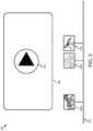
- FIG. 3illustrates an example user interface that includes a timeline of a video with thumbnails according to some embodiments.
- FIG. 4illustrates an example flow diagram for generating optimal segment parameters for a three-dimensional video according to some embodiments.
- FIG. 5illustrates an example flow diagram for re-encoding a three-dimensional video with blurred portions.
- FIG. 6illustrates an example flow diagram for generating optimal segment parameters and a probabilistic model from a training set.
- a virtual reality applicationreceives head-tracking data that describe positions of people's heads while the people are viewing a three-dimensional video.
- the head-tracking datameasures the yaw, pitch, and roll associated with people that are using a viewing device to view the three-dimensional video.
- the virtual reality applicationgenerates probabilistic model of the one or more positions of the people based on the head-tracking data.
- the probabilistic modelidentifies a probability of a viewer looking in a particular direction as a function of time. For example, if most people that view the video look straight ahead at a particular object, the direction that is directly behind most people is unlikely to be a direction that people look in.
- the virtual reality applicationgenerates video segments from the three-dimensional video.
- the video segmentsmay be a fixed length of time, such as two seconds (or three, four, etc.) or the video segments may be based on scene boundaries in the three-dimensional video.
- the virtual reality applicationdetermines a directional encoding format that projects latitudes and longitudes of locations of a surface of sphere onto locations on a plane. For example, the virtual reality application may use a map projection to take three-dimensional video content that is designed for a sphere and map it onto a plane. For each of the video segments, the virtual reality application determines a cost function that identifies a region of interest on the plane based on the probabilistic model. For example, the virtual reality application may determine that most people look in a particular direction during the video segment. For each of the video segments, the virtual reality application generates optimal segment parameters that minimize a sum-over position for the region of interest. For example, the virtual reality application generates yaw, pitch, and roll values for the segment to identify the region of interest.
- the optimal segment parametersmay be used in a variety of applications.
- the virtual reality applicationmay re-encode the three-dimensional video to include the optimal segment parameters for each of the video segments, blur portions of each of the video segments based on the probability, and provide the re-encoded video and the optimal segment parameters to a viewing device.
- the viewing devicemay use the optimal segment parameters to un-distort the re-encoded video and texture the re-encoded video to the sphere.
- a user using the viewing the three-dimensional videomay view the regions of interest at a higher resolution than the other regions in the three-dimensional video and the blurred portions of the three-dimensional video at a lower resolution than other regions in the three-dimensional video.
- FIG. 1illustrates an example virtual reality system 100 that determines optimal segment parameters for virtual reality content.
- the virtual reality system 100comprises a camera array 101 , a client device 105 , a viewing device 115 , a server 120 , and a network 125 .
- FIG. 1illustrates one camera array 101 , one client device 105 , one viewing device 115 , and one server 120
- the disclosureapplies to a system architecture having one or more camera arrays 101 , one or more client devices 105 , one or more viewing devices 115 , and one or more servers 120 .
- FIG. 1illustrates one network 125 coupled to the entities of the system 100
- one or more networks 125may be connected to these entities and the one or more networks 125 may be of various and different types.
- the camera array 101may comprise camera modules that capture video data.
- the camera array 101may communicate with the client device 105 and/or the server 120 by accessing the network 125 via signal line 102 .
- Signal line 102may represent a wireless or a wired connection.
- the camera array 101may wirelessly transmit video data over the network 125 to the server 120 .
- the camera array 101may be directly connected to the client device 105 .
- the camera array 101may be connected to the client device 105 via a universal serial bus (USB) cable.
- USBuniversal serial bus
- the network 125may be a conventional type, wired or wireless, and may have numerous different configurations including a star configuration, token ring configuration, or other configurations. Furthermore, the network 125 may include a local area network (LAN), a wide area network (WAN) (e.g., the Internet), or other interconnected data paths across which multiple devices may communicate. In some embodiments, the network 125 may be a peer-to-peer network. The network 125 may also be coupled to or include portions of a telecommunications network for sending data in a variety of different communication protocols.
- LANlocal area network
- WANwide area network
- the network 125may also be coupled to or include portions of a telecommunications network for sending data in a variety of different communication protocols.
- the network 125may include BluetoothTM communication networks or a cellular communication network for sending and receiving data including via short messaging service (SMS), multimedia messaging service (MMS), hypertext transfer protocol (HTTP), direct data connection, wireless access protocol (WAP), e-mail, etc.
- SMSshort messaging service
- MMSmultimedia messaging service
- HTTPhypertext transfer protocol
- WAPwireless access protocol
- e-mailetc.
- the client device 105may be a processor-based computing device.
- the client device 105may be a personal computer, laptop, tablet computing device, smartphone, set top box, network-enabled television, or any other processor based computing device.
- the client device 105includes network functionality and is communicatively coupled to the network 125 via a signal line 104 .
- the client device 105may be configured to transmit data to the server 120 or to receive data from the server 120 via the network 125 .
- a user 110may access the client device 105 .
- the client device 105may include a virtual reality (VR) application 103 a .
- the virtual reality application 103 amay be configured to control the camera array 101 and/or aggregate video data and audio data to generate a stream of three-dimensional video data.
- the virtual reality application 103 acan be implemented using hardware including a field-programmable gate array (“FPGA”) or an application-specific integrated circuit (“ASIC”).
- FPGAfield-programmable gate array
- ASICapplication-specific integrated circuit
- the virtual reality application 103 amay be implemented using a combination of hardware and software.
- the server 120may be a hardware server that includes a processor, a memory, a database 107 , and network communication capabilities.
- the server 120is coupled to the network 125 via signal line 108 .
- the server 120sends and receives data to and from one or more of the other entities of the system 100 via the network 125 .
- the server 120receives virtual reality content including a stream of three-dimensional video data (or compressed three-dimensional video data) from the camera array 101 and/or the client device 105 and stores the virtual reality content on a storage device (e.g., the database 107 ) associated with the server 120 .
- the database 107may store a set of three-dimensional videos that are used to generate head-tracking data.
- the virtual reality application 103 bmay use the head-tracking data to estimate a probabilistic model for a three-dimensional video that is not part of the set of three-dimensional videos.
- the server 120may include a virtual reality application 103 b that receives video data and audio data from the client device 105 and/or the camera array 101 and aggregates the video data to generate the virtual reality content.
- the virtual reality application 103 bmay generate the optimal segment parameters for the three-dimensional video.
- the viewing device 115may be operable to display virtual reality content.
- the viewing device 115may include or use a computing device to decode and render a stream of three-dimensional video data on a virtual reality display device (e.g., Oculus Rift virtual reality display) or other suitable display devices that include, but are not limited to: augmented reality glasses; televisions, smartphones, tablets, or other devices with three-dimensional displays and/or position tracking sensors; and display devices with a viewing position control, etc.
- the viewing device 115may also decode and render a stream of three-dimensional audio data on an audio reproduction device (e.g., a headphone or other suitable speaker devices).
- the viewing device 115may include the virtual reality display configured to render the three-dimensional video data and the audio reproduction device configured to render the three-dimensional audio data.
- the viewing device 115may be coupled to the network 125 via signal line 106 .
- the viewing device 115may communicate with the client device 105 and/or the server 120 via the network 125 or via a direct connection with the client device 105 (not shown).
- a user 113may interact with the viewing device 115 .
- the user 113may be the same or different from the user 110 that accesses the client device 105 .
- the viewing device 115receives virtual reality content from the client device 105 .
- the viewing device 115receives the virtual reality content from the server 120 .
- the virtual reality contentmay include one or more of a stream of three-dimensional video data, a stream of three-dimensional audio data, a compressed stream of three-dimensional video data, a compressed stream of three-dimensional audio data, and other suitable content.
- the viewing device 115 and the client device 105may be the same device.
- the viewing device 115may track a head orientation of a user 113 while the user 113 is viewing three-dimensional video.
- the viewing device 115may include one or more accelerometers or gyroscopes used to detect a change in the user's 113 head orientation.
- the viewing device 115may decode and render the stream of three-dimensional video data on a virtual reality display device based on the head orientation of the user 113 .
- the viewing device 115may adjust the rendering of the three-dimensional video data and three-dimensional audio data based on the changes of the user's 113 head orientation.
- the viewing device 115may log head-tracking data and transmit the head-tracking data to the virtual reality application 103 .
- the viewing device 115may include some or all of the components of the virtual reality application 103 described below.
- the virtual reality application 103may receive the head-tracking data corresponding to the three-dimensional video from the viewing device 115 .
- the virtual reality application 103may generate video segments from the three-dimensional video and determine optimal segment parameters for each of the video segments based on the head-tracking data. For example, the virtual reality application 103 may receive head-tracking data for multiple users 113 and determine from the head-tracking data that most users 113 have particular head orientations during the viewing. The particular head orientations could include looking upwards as a bird is displayed as flying overhead, moving from left to right as a car is displayed as driving past the user 113 , etc.
- the virtual reality application 103may transmit the optimal segment parameters to the viewing device 115 , which may use the optimal segment parameters to re-encode the three-dimensional video.
- the viewing device 115may re-encode the three-dimensional video to include regions of interest (i.e., one or more areas where users 113 were more likely to look) with a higher resolution than other regions of the three-dimensional video.
- FIG. 2illustrates an example computing device 200 that generates three-dimensional video according to some embodiments.
- the computing device 200may be the server 120 or the client device 105 .
- the computing device 200may include a special-purpose computing device configured to provide some or all of the functionality described below with reference to FIG. 2 .
- FIG. 2may include a processor 222 , a memory 224 , a communication unit 226 , and a display 228 .
- the processor 222 , the memory 224 , the communication unit 226 , and the display 228are communicatively coupled to the bus 220 .
- Other hardware componentsmay be part of the computing device 200 , such as sensors (e.g., a gyroscope, accelerometer), etc.
- the processor 222may include an arithmetic logic unit, a microprocessor, a general-purpose controller, or some other processor array to perform computations and provide electronic display signals to a display device.
- the processor 222processes data signals and may include various computing architectures including a complex instruction set computer (CISC) architecture, a reduced instruction set computer (RISC) architecture, or an architecture implementing a combination of instruction sets.
- FIG. 2includes a single processor 222 , multiple processors may be included. Other processors, operating systems, sensors, displays, and physical configurations may be possible.
- the processor 222is coupled to the bus 220 for communication with the other components via signal line 203 .
- the memory 224stores instructions or data that may be executed by the processor 222 .
- the instructions or datamay include code for performing the techniques described herein.
- the memory 224may store the virtual reality application 103 , which may be a series of modules that include instructions or data for generating three-dimensional videos.
- the memory 224may include a dynamic random access memory (DRAM) device, a static random access memory (SRAM) device, flash memory, or some other memory device.
- the memory 224also includes a non-volatile memory or similar permanent storage device and media including a hard disk drive, a CD-ROM device, a DVD-ROM device, a DVD-RAM device, a DVD-RW device, a flash memory device, or some other mass storage device for storing information on a more permanent basis.
- the memory 224is coupled to the bus 220 for communication with the other components via signal line 205 .
- the communication unit 226may include hardware that transmits and receives data to and from the camera array 101 , the viewing device 115 , and the client device 105 or the server 120 , depending on whether the virtual reality application 103 is stored on the server 120 or the client device 105 , respectively.
- the communication unit 226is coupled to the bus 220 via signal line 207 .
- the communication unit 226includes one or more ports for direct physical connection to the network 125 or another communication channel.
- the communication unit 226includes a USB, SD, CAT-5, or similar port for wired communication with the computing device 200 .
- the communication unit 226includes a wireless transceiver for exchanging data with the computing device 200 or other communication channels using one or more wireless communication methods, including IEEE 802.11, IEEE 802.16, Bluetooth®, or another suitable wireless communication method.
- the communication unit 226includes a cellular communications transceiver for sending and receiving data over a cellular communications network including via short messaging service (SMS), multimedia messaging service (MMS), hypertext transfer protocol (HTTP), direct data connection, WAP, e-mail, or another suitable type of electronic communication.
- SMSshort messaging service
- MMSmultimedia messaging service
- HTTPhypertext transfer protocol
- the communication unit 226includes a wired port and a wireless transceiver.
- the communication unit 226also provides other conventional connections to the network 125 for distribution of files or media objects using standard network protocols including TCP/IP, HTTP, HTTPS, and SMTP, etc.
- the display 228may include hardware for displaying graphical data from the virtual reality application 103 .
- the display 228renders graphics for displaying a user interface where a user may view a two-dimensional video that was generated from a three-dimensional video.
- the display 228is coupled to the bus 220 via signal line 209 .
- the display 228is optional hardware that may not be included in the computing device 200 , for example, if the computing device 200 is a server.
- the virtual reality application 103may include an aggregation module 202 , a head tracking module 204 , a segmentation module 206 , a parameterization module 208 , an encoder module 210 , and a user interface module 212 .
- the modulesare illustrated as being part of the same computing device 200 , in some embodiments some of the modules are stored on the server 120 and some of the modules are stored on the client device 105 .
- the server 120may include the head tracking module 204 , the segmentation module 206 , the parameterization module, and the encoder module 210 and the client device 105 may include the user interface module 212 .
- the aggregation module 202may include code and routines for aggregating video data.
- the aggregation module 202includes a set of instructions executable by the processor 222 to aggregate video data.
- the aggregation module 202is stored in the memory 224 of the computing device 200 and is accessible and executable by the processor 222 .
- the aggregation module 202may be part of a separate application.
- the aggregation module 202may receive video data from the camera array 101 .
- the video dataincludes separate video recordings for each camera module included in the camera array 101 and a device identifier (ID) that identifies the camera module corresponding to each separate video recording.
- IDdevice identifier
- a two-dimensional (2D) spherical panoramic imagemay be used to represent a panorama of an entire scene.
- the aggregation module 202may generate two stereoscopic panorama images for two eyes to provide a stereoscopic view of the entire scene. For example, a left panoramic image may be generated for the left eye viewing and a right panoramic image may be generated for the right eye viewing.
- a pixel in a panoramic imagemay be represented by a yaw value and a pitch value.
- Yawhas a value between 0° and 360°.
- Pitchhas a value between ⁇ 90° and 90°.
- Typical stereoscopic systemsmay respectively show two different planar images to two eyes to create a sense of depth.
- all pixels in the imagerepresent a single eye viewing position.
- all pixels in the planar imagemay represent a view into the same viewing direction.
- each pixel in the panoramic imagemay represent a view into a slightly different direction.
- a blended panorama for eye viewing positions with all 360-degree head rotations in the horizontal axismay be produced.
- the blended panoramais effective for head rotations along the horizontal axis (e.g., yaw) but not for the vertical axis (e.g., pitch).
- the maximum value of the interocular distancemay be about 60 millimeters. In other examples, the maximum value of the interocular distance may have a value greater than 60 millimeters or less than 60 millimeters.
- the aggregation module 202may construct a left camera mapping map for each pixel in a left panoramic image. For example, for a pixel in a left panoramic image that represents a point in a panorama, the left camera mapping map may identify matching camera modules from a camera array with spherical modules that have each a better view for the point in the panorama than other camera modules. Thus, the left camera mapping map may map pixels in a left panoramic image to matching camera modules that have better views for the corresponding pixels.
- the aggregation module 202may determine a yaw, a pitch, and an interocular distance using the above mathematical expressions (1), (2), and (3), respectively.
- the aggregation module 202may use the yaw and pitch to construct a vector representing a viewing direction of the left eye (e.g., a left viewing direction) to the corresponding point in the panorama.
- the aggregation module 202may construct a right camera mapping map that identifies a corresponding matching camera module for each pixel in a right panoramic image. For example, for a pixel in a right panoramic image that represents a point in a panorama, the right camera mapping map may identify a matching camera module that has a better view for the point in the panorama than other camera modules. Thus, the right camera mapping map may map pixels in a right panoramic image to matching camera modules that have better views for the corresponding pixels.
- the aggregation module 202may determine a yaw, a pitch, and an interocular distance using the above mathematical expressions, respectively.
- the aggregation module 202may use the yaw and pitch to construct a vector representing a viewing direction of the right eye (e.g., a right viewing direction) to the corresponding point in the panorama.
- the aggregation module 202may receive video recordings that describe image frames from the various camera modules in a camera array.
- the aggregation module 202identifies a location and timing associated with each of the camera modules and synchronizes the image frames based on locations and timings of the camera modules.
- the aggregation module 202synchronizes image frames captured by different camera modules at the same time frames.
- the aggregation module 202receives a first video recording with first images from a first camera module and a second video recording with second images from a second camera module.
- the pixel in the left panoramic image PI L,i and the corresponding pixel in the image frame of the matching camera modulemay correspond to the same point in the panorama.
- the pixel in the right panoramic image PI R,i and the corresponding pixel in the image frame of the matching camera modulemay correspond to the same point in the panorama.
- the aggregation module 202may obtain virtual reality content from the stream of left panoramic images, the stream of right panoramic images, and the audio data by sending one or more of the stream of left panoramic images, the stream of right panoramic images, and the audio data to the encoder module 210 for encoding.
- the encoder module 210may compress the stream of left panoramic images and the stream of right panoramic images to generate a stream of compressed three-dimensional video data using video compression techniques.
- the encoder module 210may use redundant information from one frame to a next frame to reduce the size of the corresponding stream. For example, with reference to a first image frame (e.g., a reference frame), redundant information in the next image frames may be removed to reduce the size of the next image frames. This compression may be referred to as temporal or inter-frame compression within the same stream of left or right panoramic images.
- the encoder module 210may use one stream (either the stream of left panoramic images or the stream of right panoramic images) as a reference stream and may compress the other stream based on the reference stream. This compression may be referred to as inter-stream compression.
- the encoder module 210may use each left panoramic image as a reference frame for a corresponding right panoramic image and may compress the corresponding right panoramic image based on the referenced left panoramic image.
- the encoding processis discussed in greater detail below with reference to the encoder module 210 .
- the aggregation module 202may transmit, via the communication unit 226 , the three-dimensional video to the viewing device 115 .
- the head tracking module 204may include code and routines for receiving head tracking data and generating a probabilistic model.
- the head tracking module 204includes a set of instructions executable by the processor 222 to receive head tracking data and generate the probabilistic model.
- the head tracking module 204is stored in the memory 224 of the computing device 200 and is accessible and executable by the processor 222 .
- the head tracking module 204may receive head tracking data from the viewing device 115 that corresponds to a three-dimensional video.
- the head tracking datamay describe a person's head movement as the person watches the three-dimensional video.
- the head tracking datamay reflect that a person moved her head up and to the right to look at an image of a squirrel in a tree.
- the head tracking dataincludes yaw (i.e., rotation around a vertical axis), pitch (i.e., rotation around a side-to-side axis), and roll (i.e., rotation around a front-to-back axis) for a person as a function of time that corresponds to the three-dimensional video.
- the head tracking module 204determines a head-mounted display position for each person at a particular frequency, such as 10 Hz throughout the three-dimensional video.
- the head tracking module 204generates user profiles based on the head tracking data. For example, the head tracking module 204 may aggregate head tracking data from multiple people and organize it according to a first most common region of interest in the three-dimensional video, a second most common region of interest in the three-dimensional video, and a third most common region of interest in the three-dimensional video. In some embodiments, the head tracking module 204 may generate user profiles based on demographic information corresponding to the people. For example, the head tracking module 204 may generate a user profile based on age, gender, etc. In some embodiments, the head tracking module 204 may generate a user profile based on physical characteristics. For example, the head tracking module 204 may identify people that move frequently while viewing the three-dimensional video and people that move very little. In some embodiments, the head tracking module 204 generates a user profile for a particular user.
- the head tracking module 204generates a probabilistic model of one or more positions of people that view a three-dimensional video.
- the probabilistic modelidentifies a probability of a viewer looking in a particular direction as a function of time. For example, the probabilistic model identifies that a viewer will likely look at a particular object as it moves in the three-dimensional video and that the viewer is unlikely to look direction behind the current location where the viewer is looking.
- the head tracking module 204may generate the probabilistic model on a pixel-by-pixel basis, based on regions in the view, such as a field-of-view, equal-sized divisions of the sphere, etc.
- the probabilistic modelmay include a heat map.
- the heat mapmay be rendered as a sequence of false-colored images.
- the probabilistic modelis displayed as an overlay on top of the three-dimensional video. In some embodiments, the probabilistic model is not displayed but is instead used by the encoder module 210 as described below.
- the parameterization module 208uses the probabilistic model to determine where one or more people are looking. For example, analysis of one or more probabilistic models may indicate that people frequently look in particular direction when watching a given piece of virtual reality content. Subsequent people may benefit from this information since it may help them to know where they should be looking when watching the virtual reality content.
- the encoder module 210may present recommendations to people about where they should be looking when viewing virtual reality content.
- the recommendationsmay be audio cues, visual cues or a combination of audio and visual cues.
- the visual cuesmay include blurring every portion of the virtual reality content except for the recommended location where a viewer should be looking.
- the head tracking module 204may use artificial intelligence to generate a set of probabilistic models from a set of three-dimensional videos.
- the database 107 stored on the server 120may include all three-dimensional videos offered by a company that generates virtual reality content.
- the head tracking module 204may use head-tracking data from users that view those three-dimensional videos as a training set for generating the set of probabilistic models.
- the head tracking module 204may include a neural network that is trained using the set of probabilistic models to determine a probabilistic distribution of viewer gaze.
- the artificial intelligencemay be used iteratively, such that each time a new three-dimensional video is generated, the head tracking module 204 uses artificial intelligence (e.g., the neural network) to generate a probabilistic model for the new three-dimensional video. This advantageously results in the creation of probabilistic models for three-dimensional videos that have never been watched.
- artificial intelligencee.g., the neural network
- the segmentation module 206may include code and routines for generating video segments from the three-dimensional video.
- the segmentation module 206includes a set of instructions executable by the processor 222 to generate the video segments.
- the segmentation module 206is stored in the memory 224 of the computing device 200 and is accessible and executable by the processor 222 .
- the segmentation module 206generates video segments from the three-dimensional video. In some embodiments, the segmentation module 206 generates equal-length video segments of a predetermined length. For example, the segmentation module 206 divides a three-minute three-dimensional video into 360 two-second segments. In some embodiments, the segmentation module 206 detects scene boundaries in the three-dimensional video and segments the three-dimensional video based on the scene boundaries. For example, the segmentation module 206 compares a first frame to a next frame to identify differences that indicate a transition between shots. When the segmentation module 206 detects the transition between shots, the segmentation module 206 generates a segment that includes the shot. In some embodiments, the segmentation module 206 may generate segments using a combination of detection of scene boundaries and timing. For example, the segmentation module 206 may first segment the three-dimensional video based on transitions between shots and further segment if any shots exceed a predetermined length of time, such as five seconds.
- a predetermined length of timesuch as five seconds.
- the parameterization module 208may include code and routines for generating optimal segment parameters.
- the parameterization module 208includes a set of instructions executable by the processor 222 to generate the optimal segment parameters.
- the parameterization module 208is stored in the memory 224 of the computing device 200 and is accessible and executable by the processor 222 .
- the parameterization module 208converts the locations on the surface of the sphere into a plane.
- the parameterization module 208may use a map projection to transform the latitudes and longitudes of locations on the surface of the sphere into locations on a plane.
- the parameterization module 208determines a directional encoding format (i.e., a map projection) that projects latitudes and longitudes of locations of the surface of the sphere into locations on the plane.
- the directional encoding formati.e., the projection of the latitudes and longitudes of locations of the surface of the sphere may be represented by the following equation: f (yaw,pitch,roll,parameters) ⁇ resolution Eq. (1a)
- the yaw, pitch, and roll valuesare obtained from the head-tracking data and/or the probabilistic model.
- the yaw, pitch, and roll valuesdescribes a position of a person that is viewing the three-dimensional video as a function of time.
- the yaw, pitch, and roll valuesmay include head-tracking data that is aggregated for multiple people that view the three-dimensional video.
- the parametersrepresent a location in the plane and the resolution is the resolution of the three-dimensional video at a region that corresponds to the yaw, pitch, and roll values.
- the directional encoding formatmay be represented by the following equation: f (parameters(pitch,yaw)) ⁇ resolution Eq. (1b)
- the parameterization module 208may design a cost function that gives a measure of perceived resolution (e.g., a geometric mean of horizontal and vertical pixels per degree at a display center) for a user gazing in a particular direction at a particular timestamp for a particular set of parameters for the projection. For example, where the latitude/longitude is 0 on the sphere, the particular set of parameters may indicate how biased the encoding is towards its high-resolution region.
- the total cost functionmay be defined as a sum of the individual costs as a function of optimal segment parameters at a particular point in the three-dimensional video.
- the parameterization module 208uses the cost function to identify a region of interest on the plane based on the head-tracking data and/or the probabilistic model by minimizing a total cost for all users that viewed the three-dimensional video. Persons of ordinary skill in the art will recognize that other cost functions may be used.
- the parameterization module 208may generate optimal segment parameters that minimize a sum-over position for the region of interest by applying the cost function.
- the optimal segment parametersmay include a (yaw, pitch) tuple that encodes the region of interest in the video segment.
- the parameterization module 208determines one or more regions of low interest based on the probabilistic model. For example, a region of low interest may include a field-of-view or other division of a three-dimensional video based on the probabilistic model.
- the parameterization module 208determines multiple directional encodings in each of the video segments for three-dimensional video to identify multiple regions of interest within the three-dimensional video. For example, the head tracking module 204 generates a first user profile and a second user profile and the parameterization module 208 generates first optimal segment parameters associated with the first user profile and second optimal segment parameters associated with the second user profile.
- the parameterization module 208may determine the multiple directional encodings using time-dependent clustering and/or a model that is similar to k-means clustering.
- a new directional encoding formatmay be designed with multiple potential regions of interest.
- the new directional encoding formatmay be converted into the above resolution and cost functions.
- the encoder module 210may include code and routines for re-encoding the three-dimensional video.
- the encoder module 210includes a set of instructions executable by the processor 222 to re-encode the three-dimensional video.
- the encoder module 210is stored in the memory 224 of the computing device 200 and is accessible and executable by the processor 222 .
- the encoder module 210may re-encode the three-dimensional video to include the optimal segment parameters for each of the video segments. For example, the encoder module 210 may re-encode the three-dimensional video by generating a re-encoded video that includes a high-resolution version of the region of interest and a lower resolution version of the other regions in the re-encoded video. The encoder module 210 may transmit, via the communication unit 226 , the re-encoded video and the optimal segment parameters for each of the video segments to the viewing device 115 .
- the encoder module 210re-encodes the three-dimensional video by blurring portions of the three-dimensional video.
- the encoder module 210may blur on a pixel-by-pixel basis according to a probability that the viewer is looking at a particular pixel based on the probabilistic model.
- the encoder module 210may blur based on regions of interest or regions of low interest.
- the encoder module 210blurs each of the video segments with varying intensity such that the intensity of a level of blur increases as the probability of a viewer looking in a particular direction decreases.
- a video segment with a single moving objectmay include the region around the moving object optimized to include high resolution, the area surrounding the moving object including slightly lower resolution, the top and bottom of the video segment including significant blur etc.
- the encoder module 210re-encodes the three-dimensional video to include optimal segment parameters for each of the video segments and/or blurs portions of each of the video segments responsive to a threshold number of people viewing the three-dimensional video. For example, if only two people viewed the three-dimensional video, the head-tracking data generated from those people viewing the three-dimensional video may be insufficient to reliably predict a probability of a viewer looking in a particular location.
- the viewing device 115may receive the re-encoded video and the optimal segment parameters for each of the video segments from the encoder module 210 .
- the viewing device 115may use the optimal segment parameters for each of the video segments to un-distort the re-encoded video and texture the re-encoded video to the sphere to display the re-encoded video with the region of interest for each of the video segments displayed at a higher resolution that other regions in each of the video segments.
- the encoder module 210re-encodes the three-dimensional video to include different sets of optimal segment parameters.
- the head track module 204may generate a first user profile that reflects a most common region in each of the video segments and a second user profile that reflects a second most common region in each of the video segments.
- the parameterization module 208may generate first optimal segment parameters associated with the first user profile and second optimal segment parameters associated with the second user profile.
- the encoder module 210may re-encode the three-dimensional video to include the first optimal segment parameters and the second optimal segment parameters for each of the video segments.
- the encoder module 210may provide the re-encoded video, the first optimal segment parameters for each of the video segments, and the second optimal segment parameters for each of the video segments to the viewing device 115 .
- the viewing device 115may un-distort the re-encoded video and texture the re-encoded video to the sphere to display the re-encoded video with two regions of interest for each of the video segments displayed at a higher resolution than other regions in each of the video segments.
- the head-track module 204may generate multiple user profiles where different people were looking at the same region of interest for a particular video segment. For example, the head-track module 204 may generate different user profiles based on the age of the people that viewed the three-dimensional video. There may be instances where the people in the different age groups looked at the same object in the three-dimensional video because the object was moving fast, making a loud noise, etc. As a result, in some embodiments, the encoder module 210 may re-encode the three-dimensional video to include a single region of interest at a higher resolution than other regions of interest for a video segment even though the re-encoded video is based on multiple sets of segment parameters. In some embodiments where the head-track module 204 generates a user profile for a particular user, the encoder module 210 may re-encode the three-dimensional video for a user based on the user profile for the particular user.
- the encoder module 210re-encodes the three-dimensional video for use as a two-dimensional video.
- the encoder module 210re-encodes the three-dimensional video to include the optimal segment parameters for each of the video segments and provides a re-encoded video and the optimal segment parameters for each of the video segments to the client device 105 or the viewing device 115 .
- the client device 105may be used for browser-based players that display the two-dimensional video, for example, on a computer screen.
- the viewing device 115may be used, for example, when a user wants to switch from an interactive three-dimensional video to an autopilot mode that displays a two-dimensional video that does all the work for the user.
- the client device 105 or the viewing device 115may use the re-encoded video and the optimal segment parameters for each of the video segments to generate a two-dimensional video that automates head movement.
- the optimal segment parameters for each video segmentprovide a model for how a user moves while watching the three-dimensional video.
- the two-dimensional videomay automate pitch and yaw movements to simulate the model based on the optimal segment parameters. This may advantageously allow users to view an autopilot mode that automates the three-dimensional movement without having to control the two-dimensional video themselves by using, for example, a mouse, joystick, keys, etc.
- the encoder module 210generates the two-dimensional video from the three-dimensional video based on the optimal segment parameters. Because the optimal segment parameters for a video segment indicate a region of interest in the video segment, the encoder module 210 may generate a two-dimensional video that depicts head tracking movement as automatic panning within the two-dimensional video. For example, the encoder module 210 may convert a three-dimensional video that includes a bird flying overhead to a two-dimensional video where it appears as if the camera moves overhead to look at the bird, the way a person viewing the three-dimensional video would move. This may advantageously allow a person viewing content on his desktop computer to have a simulated virtual-reality experience.
- the encoder module 210may generate a two-dimensional video from the three-dimensional video that includes multiple optimal segment parameters. For example, the encoder module 210 may generate the two-dimensional video based on multiple user profiles created based on a first most common region of interest and a second most common region of interest, demographics information, etc.
- the encoder module 210may compress the three-dimensional video to generate a stream of compressed three-dimensional video data using video compression techniques. Because portions of the three-dimensional video may include blurring, the three-dimensional video may be more compressible than traditional three-dimensional videos.
- the aggregation module 202may encode the stream of three-dimensional video data (or compressed three-dimensional video data) and audio data to form a stream of three-dimensional video.
- the encoder module 210may compress the stream of three-dimensional video data using h.264 and the stream of three-dimensional audio data using advanced audio coding (AAC).
- AACadvanced audio coding
- the encoder module 210may compress the stream of three-dimensional video data and the stream of three-dimensional audio data using a standard MPEG format.
- the user interface module 212may include code and routines for generating a user interface.
- the user interface module 212includes a set of instructions executable by the processor 222 to generate the user interface.
- the user interface module 212is stored in the memory 224 of the computing device 200 and is accessible and executable by the processor 222 .
- the user interface module 212may generate a user interface that includes options for manipulating the camera array 101 .
- the user interfacemay include options for determining whether the camera array 101 starts and stops recording.
- the user interfacemay also include an option for viewing a preview of the video data captured by the camera array 101 .
- the user interface module 212may generate a user interface that includes options for viewing the three-dimensional video or a two-dimensional video generated from the three-dimensional video.
- the optionsmay include starting and stopping a video.
- the user interfaceincludes a timeline of the video and an option to view the video starting at a section on the timeline.
- the user interface module 212crops the region of interest for one or more of the video segments based on the optimal segment parameters to form one or more thumbnails of one or more cropped regions of interest. For example, the user interface module 212 may select a predetermined number of regions of interest to crop in the video segments. In some embodiments, the user interface module 212 may determine based on the head-tracking data that regions of interest where a threshold percentage of people looked at the same region of interest that the region of interest qualifies for cropping. For example, if the three-dimensional video includes an explosion and 98% of the people looked at the explosion, the user interface module 212 may determine that the 98% exceeds the threshold percentage of 75% and crop the region of interest. The user interface module 212 may generate a timeline of the three-dimensional video that includes the thumbnails.
- an example user interface 300includes a video screen 305 for displaying a video and a timeline 310 .
- the videomay be a three-dimensional video or a two-dimensional video generated from the three-dimensional video.
- the video screen 305includes a play button 315 for starting the video.
- the timeline 310includes three thumbnails 320 : a first thumbnail 320 a of a zebra, a second thumbnail 320 b of a peacock, and a third thumbnail 320 c of a killdeer.
- the thumbnails 320( 320 a , 320 b , 320 c ) include a cropped version of the regions of interest in the video.
- the user interface module 212generated the three thumbnails based on a percentage of people viewing the region of interest in each of the video segments exceeding a threshold percentage.
- the user interface module 212generates a user interface that include an option for the user to modify the two-dimensional video.
- the user interfacemay include an option to switch from the first user profile to the second user profile.
- the client device 105may switch from using the re-encoded video and first optimal segment parameters to using the re-encoded video and second optimal segment parameters to generate the two-dimensional video.
- the user interfacemay provide descriptions for different user profiles, such as most common for the most common regions of interest, second most common, slow movement for head-tracking data associated with people that move slowly while viewing the three-dimensional video, fast movement for head-tracking data associated with people that move quickly while viewing the three-dimensional video, etc.
- the user interfacemay include an option for the user to modify the two-dimensional video by directly inputting a pitch and yaw.
- the usermay use a pointing device, such as a mouse, to select a region of interest in the two-dimensional video.
- the client device 105may identify the pitch and yaw associated with the region of interest that the user selected.
- the client device 105may use the pitch and yaw as optimal segment parameters to modify the two-dimensional video, for example, by displaying more detail for the selected region of interest.
- the client device 105may identify movement associated with the selection.
- the client device 105may identify mouse movement in an upward direction.
- the client device 105may, as a result, display the two-dimensional video as panning upwards.
- the usermay directly input the pitch and yaw based on gyroscopic input. For example, if a user is viewing the two-dimensional video on a viewing device 115 , the user's head may move upwards. A gyroscope associated with the viewing device 115 may detect the upward movement and modify the two-dimensional view to display the two-dimensional video as panning upwards.
- the client device 105may be a mobile device, such as a smartphone, that includes a gyroscope that detects a user rotating the client device 105 to simulate upward movement. The client device 105 may modify the two-dimensional view to display the two-dimensional video as panning upwards based on the user rotating the client device 105 .
- FIG. 4illustrates an example flow diagram 400 for generating three-dimensional video according to some embodiments.
- the steps in FIG. 4may be performed by the virtual reality application 103 a stored on the client device 105 , the virtual reality application 103 b stored on the server 120 , or a combination of the virtual reality application 103 a stored on the client device 105 and the virtual reality application 103 b the server 120 .
- head-tracking datais received that describes one or more positions of one or more people while the one or more people are viewing a three-dimensional video (3D) on one or more viewing devices 115 .
- video segmentsare generated for the three-dimensional video.
- the three-dimensional videomay be divided into video segments that are each two seconds long.
- a directional encoding formatis determined that projects latitudes and longitudes of locations of a surface of a sphere into locations on a plane
- a cost functionis determined that identifies a region of interest on the plane based on the head-tracking data
- optimal segment parametersare generated that minimize a sum-over position for the region of interest.
- FIG. 5illustrates an example flow diagram 500 for re-encoding a three-dimensional video with blurred portions.
- the steps in FIG. 5may be performed by the virtual reality application 103 a stored on the client device 105 , the virtual reality application 103 b stored on the server 120 , or a combination of the virtual reality application 103 a stored on the client device 105 and the virtual reality application 103 b the server 120 .
- head-tracking datais received that describes one or more positions of people while the people are viewing a three-dimensional video on viewing devices 115 .
- a probabilistic model of the one or more positions of the peopleis generated based on the head-tracking data, where the probabilistic model identifies a probability of a viewer looking in a particular direction as a function of time.
- the probabilistic modelmay include a heat map that includes a visual representation of the probability that a viewer is looking in a particular direction as a function of time.
- video segmentsare generated from the three-dimensional video.
- determine a directional encoding formatthat projects latitudes and longitudes of locations of a surface of a sphere onto locations on a plane, determine a cost function that identifies a region of interest on the plane based on the probabilistic model, generate optimal segment parameters that minimize a sum-over position for the region of interest, and identify a probability of a viewer looking in a particular direction as a function of time based on the probabilistic model.
- the three-dimensional videois re-encoded to include the optimal segment parameters for each of the video segments and to blur portions of each of the video segments based on the probability, where an intensity of a level of blur increases as the probability of the viewer looking in the particular direction decreases.
- FIG. 6illustrates an example flow diagram 600 for generating optimal segment parameters and a probabilistic model from a training set.
- the steps in FIG. 6may be performed by the virtual reality application 103 a stored on the client device 105 , the virtual reality application 103 b stored on the server 120 , or a combination of the virtual reality application 103 a stored on the client device 105 and the virtual reality application 103 b the server 120 .
- head-tracking datais received that describes one or more positions of people while the people are viewing a set of three-dimensional videos.
- the set of three-dimensional videosmay include all the three-dimensional videos associated with a company that produces virtual-reality content.
- the companymay provide the set of three-dimensional videos to users and receive, after receiving user consent, the head-track data after the users watch the virtual reality content.
- a set of probabilistic modelsis generated of the one or more positions of the people based on the head-tracking data.
- the set of probabilistic modelsdescribe the probability of a viewer looking in a particular direction for a corresponding three-dimensional video.
- a first probabilistic model for a first three-dimensional videois estimated, where the first three-dimensional video is not part of the set of three-dimensional videos.
- the set of three-dimensional videosserve as a training set for a neural network that can estimate the probability of a viewer looking in a particular direction in the first three-dimensional video. This advantageously allows the first probabilistic model to be generated without the expense associated with having people view the first three-dimensional video to generate the first probabilistic model.
- a directional encoding formatis determined that projects latitudes and longitudes of locations of a surface of a sphere onto locations on a plane
- a cost functionis determined that identifies a region of interest on the plane based on the first probabilistic model
- optimal segment parametersare generated that minimize a sum-over position for the region of interest
- a probabilityis identified of a viewer looking in a particular direction as a function of time based on the first probabilistic model.
- Embodiments described hereincontemplate various additions, modifications, and/or omissions to the above-described panoptic virtual presence system, which has been described by way of example only. Accordingly, the above-described camera system should not be construed as limiting.
- the camera system described with respect to FIG. 1 belowmay include additional and/or different components or functionality than described above without departing from the scope of the disclosure.
- Embodiments described hereinmay be implemented using computer-readable media for carrying or having computer-executable instructions or data structures stored thereon.
- Such computer-readable mediamay be any available media that may be accessed by a general purpose or special purpose computer.
- Such computer-readable mediamay include tangible computer-readable storage media including Random Access Memory (RAM), Read-Only Memory (ROM), Electrically Erasable Programmable Read-Only Memory (EEPROM), Compact Disc Read-Only Memory (CD-ROM) or other optical disk storage, magnetic disk storage or other magnetic storage devices, flash memory devices (e.g., solid state memory devices), or any other storage medium which may be used to carry or store desired program code in the form of computer-executable instructions or data structures and which may be accessed by a general purpose or special purpose computer. Combinations of the above may also be included within the scope of computer-readable media.
- RAMRandom Access Memory
- ROMRead-Only Memory
- EEPROMElectrically Erasable Programmable Read-Only Memory
- CD-ROMCompact Disc Read-
- Computer-executable instructionscomprise, for example, instructions and data which cause a general purpose computer, special purpose computer, or special purpose processing device (e.g., one or more processors) to perform a certain function or group of functions.
- moduleor “component” may refer to specific hardware embodiments configured to perform the operations of the module or component and/or software objects or software routines that may be stored on and/or executed by general purpose hardware (e.g., computer-readable media, processing devices, etc.) of the computing system.
- general purpose hardwaree.g., computer-readable media, processing devices, etc.
- the different components, modules, engines, and services described hereinmay be implemented as objects or processes that execute on the computing system (e.g., as separate threads). While some of the system and methods described herein are generally described as being implemented in software (stored on and/or executed by general purpose hardware), specific hardware embodiments or a combination of software and specific hardware embodiments are also possible and contemplated.
- a “computing entity”may be any computing system as previously defined herein, or any module or combination of modulates running on a computing system.
Landscapes
- Engineering & Computer Science (AREA)
- Multimedia (AREA)
- Signal Processing (AREA)
- Testing, Inspecting, Measuring Of Stereoscopic Televisions And Televisions (AREA)
Abstract
Description
f(yaw,pitch,roll,parameters)→resolution Eq. (1a)
f(parameters(pitch,yaw))→resolution Eq. (1b)
cost(yaw,pitch,roll,params)=max(10−f(yaw,pitch,roll,params),0) Eq. (2a)
cost_multi(yaw,pitch,roll,parameter_sets)=max([cost(yaw,pitch,roll,param_set) for param_set in parameter_sets]) Eq. (2b)
Claims (20)
Priority Applications (1)
| Application Number | Priority Date | Filing Date | Title |
|---|---|---|---|
| US16/559,613US11025959B2 (en) | 2014-07-28 | 2019-09-03 | Probabilistic model to compress images for three-dimensional video |
Applications Claiming Priority (8)
| Application Number | Priority Date | Filing Date | Title |
|---|---|---|---|
| US14/444,938US9451162B2 (en) | 2013-08-21 | 2014-07-28 | Camera array including camera modules |
| US201462055259P | 2014-09-25 | 2014-09-25 | |
| US201562142909P | 2015-04-03 | 2015-04-03 | |
| US14/726,118US9911454B2 (en) | 2014-05-29 | 2015-05-29 | Camera array including camera modules |
| US14/842,465US10701426B1 (en) | 2014-07-28 | 2015-09-01 | Virtual reality system including social graph |
| US15/269,734US9774887B1 (en) | 2016-09-19 | 2016-09-19 | Behavioral directional encoding of three-dimensional video |
| US15/617,878US10440398B2 (en) | 2014-07-28 | 2017-06-08 | Probabilistic model to compress images for three-dimensional video |
| US16/559,613US11025959B2 (en) | 2014-07-28 | 2019-09-03 | Probabilistic model to compress images for three-dimensional video |
Related Parent Applications (1)
| Application Number | Title | Priority Date | Filing Date |
|---|---|---|---|
| US15/617,878ContinuationUS10440398B2 (en) | 2014-07-28 | 2017-06-08 | Probabilistic model to compress images for three-dimensional video |
Publications (2)
| Publication Number | Publication Date |
|---|---|
| US20190394492A1 US20190394492A1 (en) | 2019-12-26 |
| US11025959B2true US11025959B2 (en) | 2021-06-01 |
Family
ID=59896812
Family Applications (2)
| Application Number | Title | Priority Date | Filing Date |
|---|---|---|---|
| US15/617,878ActiveUS10440398B2 (en) | 2014-07-28 | 2017-06-08 | Probabilistic model to compress images for three-dimensional video |
| US16/559,613ActiveUS11025959B2 (en) | 2014-07-28 | 2019-09-03 | Probabilistic model to compress images for three-dimensional video |
Family Applications Before (1)
| Application Number | Title | Priority Date | Filing Date |
|---|---|---|---|
| US15/617,878ActiveUS10440398B2 (en) | 2014-07-28 | 2017-06-08 | Probabilistic model to compress images for three-dimensional video |
Country Status (1)
| Country | Link |
|---|---|
| US (2) | US10440398B2 (en) |
Families Citing this family (24)
| Publication number | Priority date | Publication date | Assignee | Title |
|---|---|---|---|---|
| US11277598B2 (en)* | 2009-07-14 | 2022-03-15 | Cable Television Laboratories, Inc. | Systems and methods for network-based media processing |
| US11019258B2 (en) | 2013-08-21 | 2021-05-25 | Verizon Patent And Licensing Inc. | Aggregating images and audio data to generate content |
| US9451162B2 (en) | 2013-08-21 | 2016-09-20 | Jaunt Inc. | Camera array including camera modules |
| US11108971B2 (en) | 2014-07-25 | 2021-08-31 | Verzon Patent and Licensing Ine. | Camera array removing lens distortion |
| US10440398B2 (en)* | 2014-07-28 | 2019-10-08 | Jaunt, Inc. | Probabilistic model to compress images for three-dimensional video |
| EP3345184A1 (en)* | 2015-09-02 | 2018-07-11 | THOMSON Licensing | Method, apparatus and system for facilitating navigation in an extended scene |
| CN105450965B (en)* | 2015-12-09 | 2019-07-19 | 北京小鸟看看科技有限公司 | A kind of video conversion method, device and system |
| US11032535B2 (en) | 2016-09-19 | 2021-06-08 | Verizon Patent And Licensing Inc. | Generating a three-dimensional preview of a three-dimensional video |
| US11032536B2 (en) | 2016-09-19 | 2021-06-08 | Verizon Patent And Licensing Inc. | Generating a three-dimensional preview from a two-dimensional selectable icon of a three-dimensional reality video |
| WO2018131813A1 (en)* | 2017-01-10 | 2018-07-19 | Samsung Electronics Co., Ltd. | Method and apparatus for generating metadata for 3d images |
| US11115666B2 (en)* | 2017-08-03 | 2021-09-07 | At&T Intellectual Property I, L.P. | Semantic video encoding |
| JP6615847B2 (en)* | 2017-11-08 | 2019-12-04 | 株式会社東芝 | Image processing apparatus, image processing system, image processing method, and program |
| US10893261B2 (en)* | 2017-12-06 | 2021-01-12 | Dolby Laboratories Licensing Corporation | Positional zero latency |
| US10721510B2 (en) | 2018-05-17 | 2020-07-21 | At&T Intellectual Property I, L.P. | Directing user focus in 360 video consumption |
| US10482653B1 (en) | 2018-05-22 | 2019-11-19 | At&T Intellectual Property I, L.P. | System for active-focus prediction in 360 video |
| US10827225B2 (en) | 2018-06-01 | 2020-11-03 | AT&T Intellectual Propety I, L.P. | Navigation for 360-degree video streaming |
| CN109005409B (en)* | 2018-07-27 | 2021-04-09 | 浙江工业大学 | Intelligent video coding method based on target detection and tracking |
| US11818419B2 (en) | 2018-09-28 | 2023-11-14 | Apple Inc. | Mobile device content provisioning adjustments based on wireless communication channel bandwidth condition |
| CN110972203B (en) | 2018-09-28 | 2023-09-01 | 苹果公司 | Regulation of Electronic Equipment Content Provision Based on Wireless Communication Channel Bandwidth Conditions |
| US10812771B1 (en)* | 2019-06-12 | 2020-10-20 | At&T Intellectual Property I, L.P. | Methods, systems, and devices for adjusting image content for streaming panoramic video content |
| CN110572579B (en)* | 2019-09-30 | 2021-09-14 | 联想(北京)有限公司 | Image processing method and device and electronic equipment |
| US11470327B2 (en) | 2020-03-30 | 2022-10-11 | Alibaba Group Holding Limited | Scene aware video content encoding |
| CN112037313B (en)* | 2020-08-28 | 2022-10-14 | 西南交通大学 | VR scene optimization method based on tunnel vision |
| CN112367516B (en)* | 2020-11-09 | 2021-10-01 | 四川长虹电器股份有限公司 | Three-dimensional display system based on space positioning |
Citations (191)
| Publication number | Priority date | Publication date | Assignee | Title |
|---|---|---|---|---|
| US4507683A (en) | 1982-04-02 | 1985-03-26 | Ampex Corporation | Camera status and diagnostics display system |
| US5495576A (en) | 1993-01-11 | 1996-02-27 | Ritchey; Kurtis J. | Panoramic image based virtual reality/telepresence audio-visual system and method |
| US6128108A (en) | 1997-09-03 | 2000-10-03 | Mgi Software Corporation | Method and system for compositing images |
| US6141034A (en) | 1995-12-15 | 2000-10-31 | Immersive Media Co. | Immersive imaging method and apparatus |
| US6212468B1 (en) | 1997-05-29 | 2001-04-03 | Mitsubishi Heavy Industries, Ltd. | System for optically detecting vehicles traveling along the lanes of a road |
| US20010015751A1 (en) | 1998-06-16 | 2001-08-23 | Genex Technologies, Inc. | Method and apparatus for omnidirectional imaging |
| US20020075295A1 (en) | 2000-02-07 | 2002-06-20 | Stentz Anthony Joseph | Telepresence using panoramic imaging and directional sound |
| US20020171741A1 (en) | 1995-03-24 | 2002-11-21 | Tonkin Steven Wallace | High speed digital video serial link |
| US20030025805A1 (en) | 2001-07-31 | 2003-02-06 | Canon Kabushiki Kaisha | Image sensing apparatus, image processing apparatus and method, and image processing system |
| US20030117488A1 (en) | 2001-08-10 | 2003-06-26 | Donald Pierce | Stereoscopic panoramic image capture device |
| US20040008256A1 (en) | 2001-07-16 | 2004-01-15 | Hak-Sung Kim | Video monitoring system using daisy chain |
| US20040027451A1 (en) | 2002-04-12 | 2004-02-12 | Image Masters, Inc. | Immersive imaging system |
| US20040066449A1 (en) | 2000-11-29 | 2004-04-08 | Dor Givon | System and method for spherical stereoscopic photographing |
| US6747644B1 (en)* | 1995-08-04 | 2004-06-08 | Sun Microsystems, Inc. | Decompression of surface normals in three-dimensional graphics data |
| US6767287B1 (en) | 2000-03-16 | 2004-07-27 | Sony Computer Entertainment America Inc. | Computer system and method for implementing a virtual reality environment for a multi-player game |
| US20040196378A1 (en) | 2003-02-17 | 2004-10-07 | Axis Ab., A Swedish Corporation | Method and apparatus for panning and tilting a camera |
| US20040246333A1 (en) | 2003-06-03 | 2004-12-09 | Steuart Leonard P. (Skip) | Digital 3D/360 degree camera system |
| US6865289B1 (en) | 2000-02-07 | 2005-03-08 | Canon Kabushiki Kaisha | Detection and removal of image occlusion errors |
| US20050062869A1 (en) | 1999-04-08 | 2005-03-24 | Zimmermann Steven Dwain | Immersive video presentations |
| US20050069167A1 (en) | 2003-09-29 | 2005-03-31 | Zarrabizadeh Mohammad Hossein | Watermarking scheme for digital video |
| US20060082663A1 (en) | 2004-10-15 | 2006-04-20 | Rooy Jan V | Video camera |
| US7155680B2 (en) | 2000-12-27 | 2006-12-26 | Fujitsu Limited | Apparatus and method for providing virtual world customized for user |
| US20070027844A1 (en) | 2005-07-28 | 2007-02-01 | Microsoft Corporation | Navigating recorded multimedia content using keywords or phrases |
| US20070035627A1 (en) | 2005-08-11 | 2007-02-15 | Cleary Geoffrey A | Methods and apparatus for providing fault tolerance in a surveillance system |
| US20070097206A1 (en) | 2005-11-02 | 2007-05-03 | Houvener Robert C | Multi-user stereoscopic 3-D panoramic vision system and method |
| US20070146530A1 (en) | 2005-12-28 | 2007-06-28 | Hiroyasu Nose | Photographing apparatus, image display method, computer program and storage medium |
| US20070159527A1 (en) | 2006-01-09 | 2007-07-12 | Samsung Electronics Co., Ltd. | Method and apparatus for providing panoramic view with geometric correction |
| US20070263076A1 (en) | 2006-04-21 | 2007-11-15 | Andrews Carlton A | Virtual ring camera |
| US20080091526A1 (en) | 2006-10-17 | 2008-04-17 | Austin Shoemaker | Method and system for selecting and presenting web advertisements in a full-screen cinematic view |
| US20080143842A1 (en) | 2006-12-06 | 2008-06-19 | Sony United Kingdom Limited | Camera arrangement and method |
| US20080262910A1 (en) | 2007-04-20 | 2008-10-23 | Utbk, Inc. | Methods and Systems to Connect People via Virtual Reality for Real Time Communications |
| US20080263458A1 (en) | 2007-04-20 | 2008-10-23 | Utbk, Inc. | Methods and Systems to Facilitate Real Time Communications in Virtual Reality |
| US20090076894A1 (en) | 2007-09-13 | 2009-03-19 | Cary Lee Bates | Advertising in Virtual Environments Based on Crowd Statistics |
| US20090238378A1 (en) | 2008-03-18 | 2009-09-24 | Invism, Inc. | Enhanced Immersive Soundscapes Production |
| US20090249244A1 (en) | 2000-10-10 | 2009-10-01 | Addnclick, Inc. | Dynamic information management system and method for content delivery and sharing in content-, metadata- & viewer-based, live social networking among users concurrently engaged in the same and/or similar content |
| US20090288002A1 (en) | 2008-05-15 | 2009-11-19 | Hamilton Ii Rick A | Virtual universe teleportation suggestion service |
| US20100036735A1 (en) | 2008-08-11 | 2010-02-11 | International Business Machines Corporation | Triggering immersive advertisements in a virtual universe |
| RU2382406C1 (en) | 2008-10-10 | 2010-02-20 | Корпорация "САМСУНГ ЭЛЕКТРОНИКС Ко., Лтд." | Method of improving disparity map and device for realising said method |
| US20100045773A1 (en) | 2007-11-06 | 2010-02-25 | Ritchey Kurtis J | Panoramic adapter system and method with spherical field-of-view coverage |
| US20100083139A1 (en) | 2008-09-26 | 2010-04-01 | International Business Machines Corporation | Virtual universe avatar companion |
| US20100097444A1 (en) | 2008-10-16 | 2010-04-22 | Peter Lablans | Camera System for Creating an Image From a Plurality of Images |
| US20100100429A1 (en) | 2008-10-17 | 2010-04-22 | Microsoft Corporation | Systems and methods for using world-space coordinates of ad objects and camera information for adverstising within a vitrtual environment |
| US20100119105A1 (en) | 2008-10-28 | 2010-05-13 | Koichi Moriya | Image processing device and image processing progam |
| US20100141733A1 (en) | 2007-03-15 | 2010-06-10 | Mobotix Ag | Surveillance system |
| US20100164956A1 (en) | 2008-12-28 | 2010-07-01 | Nortel Networks Limited | Method and Apparatus for Monitoring User Attention with a Computer-Generated Virtual Environment |
| US20100169842A1 (en) | 2008-12-31 | 2010-07-01 | Microsoft Corporation | Control Function Gestures |
| US20100315479A1 (en) | 2009-06-10 | 2010-12-16 | Alcatel-Lucent Usa Inc. | System to freely configure video conferencing camera placement |
| US20100318467A1 (en) | 2006-12-06 | 2010-12-16 | Sony United Kingdom Limited | method and an apparatus for generating image content |
| US20100332980A1 (en) | 2009-06-26 | 2010-12-30 | Xerox Corporation | Managing document interactions in collaborative document environments of virtual worlds |
| US7884848B2 (en) | 2005-05-25 | 2011-02-08 | Ginther Mark E | Viewing environment and recording system |
| US20110058749A1 (en) | 2009-09-04 | 2011-03-10 | Sony Corporation | Method and apparatus for determining the mis-alignment in images |
| US20110142132A1 (en) | 2008-08-04 | 2011-06-16 | Dolby Laboratories Licensing Corporation | Overlapped Block Disparity Estimation and Compensation Architecture |
| RU2421933C2 (en) | 2009-03-24 | 2011-06-20 | Корпорация "САМСУНГ ЭЛЕКТРОНИКС Ко., Лтд." | System and method to generate and reproduce 3d video image |
| US20110157305A1 (en) | 2009-12-24 | 2011-06-30 | Sony Corporation | Image processing apparatus, image capturing apparatus, image processing method, and program |
| US20110193956A1 (en) | 2010-02-05 | 2011-08-11 | Albert Gilg | Apparatus and a method for performing a difference measurement of an object image |
| US20110267510A1 (en) | 2010-05-03 | 2011-11-03 | Malone Michael R | Devices and methods for high-resolution image and video capture |
| US20120050474A1 (en) | 2009-01-19 | 2012-03-01 | Sharp Laboratories Of America, Inc. | Stereoscopic dynamic range image sequence |
| US20120056977A1 (en) | 2010-09-06 | 2012-03-08 | Canon Kabushiki Kaisha | Method for generating panoramic image |
| US20120069236A1 (en) | 2006-08-01 | 2012-03-22 | Takaaki Namba | Camera device, liquid lens, and image pickup method |
| US20120105632A1 (en) | 2004-09-24 | 2012-05-03 | Renkis Martin A | Video Surveillance Sharing System & Method |
| US20120113278A1 (en) | 2010-11-05 | 2012-05-10 | Sony Corporation | Imaging apparatus, image processing apparatus, and image processing method, and program |
| US20120155786A1 (en) | 2010-12-17 | 2012-06-21 | Microsoft Corporation | Seamless left/right views for 360-degree stereoscopic video |
| US20120162362A1 (en) | 2010-12-22 | 2012-06-28 | Microsoft Corporation | Mapping sound spatialization fields to panoramic video |
| US20120169842A1 (en) | 2010-12-16 | 2012-07-05 | Chuang Daniel B | Imaging systems and methods for immersive surveillance |
| US20120194712A1 (en) | 2011-02-01 | 2012-08-02 | Neal Crook | Systems and methods for synchronizing and controlling multiple image sensors |
| US20120203640A1 (en) | 2011-02-03 | 2012-08-09 | U Owe Me, Inc. | Method and system of generating an implicit social graph from bioresponse data |
| WO2012113988A1 (en) | 2011-02-25 | 2012-08-30 | Nokia Corporation | Method and apparatus for feature-based presentation of content |
| US20120218376A1 (en) | 2011-02-28 | 2012-08-30 | Custom Manufacturing & Engineering, Inc. | Method and apparatus for imaging |
| US20120232998A1 (en) | 2011-03-08 | 2012-09-13 | Kent Schoen | Selecting social endorsement information for an advertisement for display to a viewing user |
| US20120240077A1 (en) | 2011-03-16 | 2012-09-20 | Nokia Corporation | Method and apparatus for displaying interactive preview information in a location-based user interface |
| US20120242794A1 (en) | 2011-03-24 | 2012-09-27 | Minwoo Park | Producing 3d images from captured 2d video |
| US20120242788A1 (en) | 2010-12-16 | 2012-09-27 | The Massachusetts Institute Of Technology | Imaging system for immersive surveillance |
| US20120257095A1 (en) | 2011-04-05 | 2012-10-11 | American Dj Supply, Inc. | Controllable led video camera system |
| US20120290401A1 (en) | 2011-05-11 | 2012-11-15 | Google Inc. | Gaze tracking system |
| US20120310717A1 (en) | 2011-05-31 | 2012-12-06 | Nokia Corporation | Method and apparatus for controlling a perspective display of advertisements using sensor data |
| US20120324493A1 (en) | 2011-06-17 | 2012-12-20 | Microsoft Corporation | Interest-based video streams |
| US20120324494A1 (en) | 2011-06-17 | 2012-12-20 | Microsoft Corporation | Selection of advertisements via viewer feedback |
| US20130016186A1 (en) | 2011-07-13 | 2013-01-17 | Qualcomm Incorporated | Method and apparatus for calibrating an imaging device |
| US20130031475A1 (en) | 2010-10-18 | 2013-01-31 | Scene 53 Inc. | Social network based virtual assembly places |
| US20130035110A1 (en) | 2011-08-02 | 2013-02-07 | Qualcomm Incorporated | Likelihood of mobile device portal transition |
| US20130044187A1 (en) | 2011-08-18 | 2013-02-21 | Sick Ag | 3d camera and method of monitoring a spatial zone |
| US20130054576A1 (en) | 2011-08-23 | 2013-02-28 | Buckyball Mobile, Inc. | Identifying digital content using bioresponse data |
| US20130080974A1 (en) | 2010-06-03 | 2013-03-28 | Nec Corporation | Region recommendation device, region recommendation method and recording medium |
| US20130083159A1 (en) | 2010-06-24 | 2013-04-04 | Fujifilm Corporation | Stereoscopic panoramic image synthesis device, image capturing device, stereoscopic panoramic image synthesis method, recording medium, and computer program |
| US20130103624A1 (en) | 2011-10-20 | 2013-04-25 | Gil Thieberger | Method and system for estimating response to token instance of interest |
| US20130117375A1 (en) | 2011-11-07 | 2013-05-09 | Anurag Bist | System and Method for Granular Tagging and Searching Multimedia Content Based on User Reaction |
| US20130124471A1 (en) | 2008-08-29 | 2013-05-16 | Simon Chen | Metadata-Driven Method and Apparatus for Multi-Image Processing |
| US8478111B2 (en) | 2008-10-03 | 2013-07-02 | 3M Innovative Properties Company | Systems and methods for optimizing a scene |
| US20130188010A1 (en) | 2012-01-20 | 2013-07-25 | Thermal Imaging Radar, LLC | Automated panoramic camera and sensor platform with computer and optional power supply |
| US20130212606A1 (en) | 2012-02-14 | 2013-08-15 | Nokia Corporation | Method and apparatus for providing social interaction with programming content |
| US20130223537A1 (en) | 2010-09-24 | 2013-08-29 | Gnzo Inc. | Video Bit Stream Transmission System |
| US20130235347A1 (en) | 2010-11-15 | 2013-09-12 | Tandemlaunch Technologies Inc. | System and Method for Interacting with and Analyzing Media on a Display Using Eye Gaze Tracking |
| US20130250047A1 (en) | 2009-05-02 | 2013-09-26 | Steven J. Hollinger | Throwable camera and network for operating the same |
| US20130258044A1 (en) | 2012-03-30 | 2013-10-03 | Zetta Research And Development Llc - Forc Series | Multi-lens camera |
| US20130259447A1 (en) | 2012-03-28 | 2013-10-03 | Nokia Corporation | Method and apparatus for user directed video editing |
| US20130266211A1 (en) | 2012-04-06 | 2013-10-10 | Brigham Young University | Stereo vision apparatus and method |
| US20130278635A1 (en) | 2011-08-25 | 2013-10-24 | Sartorius Stedim Biotech Gmbh | Assembling method, monitoring method, communication method, augmented reality system and computer program product |
| US20130278631A1 (en) | 2010-02-28 | 2013-10-24 | Osterhout Group, Inc. | 3d positioning of augmented reality information |
| US8581961B2 (en) | 2011-03-31 | 2013-11-12 | Vangogh Imaging, Inc. | Stereoscopic panoramic video capture system using surface identification and distance registration technique |
| US20140005484A1 (en) | 2012-06-27 | 2014-01-02 | CamPlex LLC | Interface for viewing video from cameras on a surgical visualization system |
| US8644596B1 (en) | 2012-06-19 | 2014-02-04 | Google Inc. | Conversion of monoscopic visual content using image-depth database |
| US20140067828A1 (en) | 2012-08-31 | 2014-03-06 | Ime Archibong | Sharing Television and Video Programming Through Social Networking |
| US20140071234A1 (en) | 2012-09-10 | 2014-03-13 | Marshall Reed Millett | Multi-dimensional data capture of an environment using plural devices |
| US8681224B2 (en) | 2007-06-26 | 2014-03-25 | Dublin City University | Method for high precision lens distortion calibration and removal |
| US20140086446A1 (en) | 2012-09-25 | 2014-03-27 | Samsung Electronics Co., Ltd. | Method and apparatus for image data processing, and electronic device including the apparatus |
| US20140089097A1 (en) | 2012-09-24 | 2014-03-27 | Naver Business Platform Corp. | Method and system for providing advertisement based on gaze of user |
| US20140099022A1 (en) | 2012-10-04 | 2014-04-10 | 3Dmedia Corporation | Image color matching and equalization devices and related methods |
| US20140097251A1 (en) | 2012-10-04 | 2014-04-10 | Cognex Corporation | Systems and methods for operating symbology reader with multi-core processor |
| US20140099623A1 (en) | 2012-10-04 | 2014-04-10 | Karmarkar V. Amit | Social graphs based on user bioresponse data |
| US20140104378A1 (en) | 2011-04-08 | 2014-04-17 | Fraunhofer-Gesellschaft Zur Foerderung Der Angewandten Forschung E.V. | Capturing panoramic or semi-panoramic 3d scenes |
| US20140125774A1 (en) | 2011-06-21 | 2014-05-08 | Vadas, Ltd. | Apparatus for synthesizing three-dimensional images to visualize surroundings of vehicle and method thereof |
| US20140126066A1 (en) | 2011-03-07 | 2014-05-08 | John Clavin | Augmented view of advertisements |
| US20140132788A1 (en) | 2012-11-09 | 2014-05-15 | Sean Geoffrey Ramsay | Systems and Methods for Generating Spherical Images |
| US20140146132A1 (en) | 2010-10-29 | 2014-05-29 | Ecole Polytechnique Federale De Lausanne (Epfl) | Omnidirectional sensor array system |
| US20140153916A1 (en) | 2012-11-05 | 2014-06-05 | 360 Heros, Inc. | 360 Degree Camera Mount and Related Photographic and Video System |
| US8750509B2 (en) | 2004-09-23 | 2014-06-10 | Smartvue Corporation | Wireless surveillance system releasably mountable to track lighting |
| US20140176749A1 (en) | 2012-12-20 | 2014-06-26 | Bradley Horowitz | Collecting Photos |
| US20140184550A1 (en) | 2011-09-07 | 2014-07-03 | Tandemlaunch Technologies Inc. | System and Method for Using Eye Gaze Information to Enhance Interactions |
| US20140201126A1 (en) | 2012-09-15 | 2014-07-17 | Lotfi A. Zadeh | Methods and Systems for Applications for Z-numbers |
| US20140232822A1 (en) | 2013-02-21 | 2014-08-21 | Pelican Imaging Corporation | Systems and methods for generating compressed light field representation data using captured light fields, array geometry, and parallax information |
| US20140237495A1 (en) | 2013-02-20 | 2014-08-21 | Samsung Electronics Co., Ltd. | Method of providing user specific interaction using device and digital television(dtv), the dtv, and the user device |
| US20140245335A1 (en) | 2013-02-25 | 2014-08-28 | Comcast Cable Communications, Llc | Environment Object Recognition |
| US20140247352A1 (en) | 2013-02-27 | 2014-09-04 | Magna Electronics Inc. | Multi-camera dynamic top view vision system |
| US20140270684A1 (en) | 2013-03-15 | 2014-09-18 | 3D-4U, Inc. | Apparatus and Method for Playback of Multiple Panoramic Videos with Control Codes |
| US20140280549A1 (en) | 2013-03-15 | 2014-09-18 | Yahoo! Inc. | Method and System for Efficient Matching of User Profiles with Audience Segments |
| US20140267596A1 (en) | 2013-03-14 | 2014-09-18 | Joergen Geerds | Camera system |
| US20140285486A1 (en) | 2013-03-20 | 2014-09-25 | Siemens Product Lifecycle Management Software Inc. | Image-based 3d panorama |
| US20140300532A1 (en) | 2013-04-08 | 2014-10-09 | Nokia Corporation | Apparatus, method and computer program for controlling a near-eye display |
| US20140310630A1 (en) | 2013-04-12 | 2014-10-16 | Navteq B.V. | Method and apparatus for providing interactive three-dimensional indoor environments |
| US20140309495A1 (en) | 2009-06-18 | 2014-10-16 | Endochoice, Inc. | Multiple Viewing Elements Endoscope System With Modular Imaging Units |
| US8867827B2 (en) | 2010-03-10 | 2014-10-21 | Shapequest, Inc. | Systems and methods for 2D image and spatial data capture for 3D stereo imaging |
| US20140320608A1 (en) | 2010-12-13 | 2014-10-30 | Nokia Corporation | Method and Apparatus for 3D Capture Synchronization |
| US20140341484A1 (en) | 2013-05-20 | 2014-11-20 | Steven Sebring | Systems and methods for producing visual representations of objects |
| US20140359647A1 (en) | 2012-12-14 | 2014-12-04 | Biscotti Inc. | Monitoring, Trend Estimation, and User Recommendations |
| US20140359656A1 (en) | 2013-05-31 | 2014-12-04 | Adobe Systems Incorporated | Placing unobtrusive overlays in video content |
| US20140368609A1 (en) | 2013-06-14 | 2014-12-18 | Omnivision Technologies, Inc. | Systems And Methods For Generating A Panoramic Image |
| US20150012827A1 (en) | 2013-03-13 | 2015-01-08 | Baback Elmeih | System and method for navigating a field of view within an interactive media-content item |
| US20150026718A1 (en) | 2013-07-19 | 2015-01-22 | United Video Properties, Inc. | Systems and methods for displaying a selectable advertisement when video has a background advertisement |
| US20150042953A1 (en) | 2011-11-09 | 2015-02-12 | Google Inc. | Measurement Method and System |
| US20150050006A1 (en) | 2013-08-19 | 2015-02-19 | Google Inc. | Content-based video segmentation |
| US20150058630A1 (en) | 2013-08-22 | 2015-02-26 | Samsung Electronics Co., Ltd. | Electronic device and method for extracting encrypted message |
| US20150067708A1 (en) | 2013-08-30 | 2015-03-05 | United Video Properties, Inc. | Systems and methods for generating media asset representations based on user emotional responses |
| US9001226B1 (en) | 2012-12-04 | 2015-04-07 | Lytro, Inc. | Capturing and relighting images using multiple devices |
| US20150124088A1 (en) | 2012-11-16 | 2015-05-07 | Scopix Inc. | Tubular camera module |
| US20150130705A1 (en) | 2013-11-12 | 2015-05-14 | Samsung Electronics Co., Ltd. | Method for determining location of content and an electronic device |
| US20150138065A1 (en) | 2013-11-21 | 2015-05-21 | Nvidia Corporation | Head-mounted integrated interface |
| US20150169076A1 (en) | 2013-12-16 | 2015-06-18 | Leap Motion, Inc. | User-defined virtual interaction space and manipulation of virtual cameras with vectors |
| US20150199006A1 (en) | 2013-11-09 | 2015-07-16 | Firima Inc. | Optical eye tracking |
| US20150206329A1 (en) | 2014-01-23 | 2015-07-23 | Derek A. Devries | Method and system of augmented-reality simulations |
| US20150208131A1 (en) | 2014-01-22 | 2015-07-23 | Sunshine Partners LLC | Viewer-interactive enhanced video advertisements |
| US20150220768A1 (en)* | 2012-09-27 | 2015-08-06 | Sensomotoric Insturments Gmbh | Tiled image based scanning for head position for eye and gaze tracking |
| US20150235434A1 (en) | 2013-03-11 | 2015-08-20 | Magic Leap, Inc. | Systems and methods for a plurality of users to interact with an augmented or virtual reality systems |
| US20150248918A1 (en) | 2014-02-28 | 2015-09-03 | United Video Properties, Inc. | Systems and methods for displaying a user selected object as marked based on its context in a program |
| US20150260526A1 (en) | 2014-03-15 | 2015-09-17 | Aurora Flight Sciences Corporation | Autonomous vehicle navigation system and method |
| US20150264092A1 (en) | 2014-03-13 | 2015-09-17 | International Business Machines Corporation | Content preview generation using social network analysis |
| US20150271483A1 (en) | 2014-03-20 | 2015-09-24 | Gopro, Inc. | Target-Less Auto-Alignment Of Image Sensors In A Multi-Camera System |
| US20150309310A1 (en) | 2014-04-23 | 2015-10-29 | Lg Electronics Inc. | Head mounted display device displaying thumbnail image and method of controlling therefor |
| US20150316982A1 (en) | 2014-04-18 | 2015-11-05 | Magic Leap, Inc. | Utilizing pseudo-random patterns for eye tracking in augmented or virtual reality systems |
| US20150317353A1 (en) | 2014-05-02 | 2015-11-05 | At&T Intellectual Property I, L.P. | Context and activity-driven playlist modification |
| US20150350561A1 (en) | 2014-05-28 | 2015-12-03 | Cambridge Silicon Radio Limited | Method for embedding product information in video using radio frequencey information |
| US20150356371A1 (en) | 2014-06-05 | 2015-12-10 | Honeywell International Inc. | Detecting camera conditions to initiate camera maintenance |
| US20150373266A1 (en) | 2014-06-19 | 2015-12-24 | Omnivision Technologies, Inc. | 360 degree multi-camera system |
| US20150379697A1 (en) | 2014-06-26 | 2015-12-31 | Daniel Pohl | Distortion meshes against chromatic aberrations |
| US20160011658A1 (en)* | 2014-04-11 | 2016-01-14 | Javier San Agustin Lopez | Systems and methods of eye tracking calibration |
| US20160027216A1 (en)* | 2014-07-25 | 2016-01-28 | Alexandre da Veiga | Three-dimensional mixed-reality viewport |
| US20160026253A1 (en) | 2014-03-11 | 2016-01-28 | Magic Leap, Inc. | Methods and systems for creating virtual and augmented reality |
| US20160037030A1 (en) | 2013-04-16 | 2016-02-04 | Fraunhofer-Gesellschaft Zur Foerderung Der Angewandten Forschung E.V. | Alignment of a camera system, camera system and alignment aid |
| US9262831B2 (en) | 2009-08-28 | 2016-02-16 | Fraunhofer-Gesellschaft zur Förderung der angewandten Forschung e.V. | Method and device for joining a plurality of individual digital images to form a total image |
| US9264598B1 (en) | 2012-12-12 | 2016-02-16 | Amazon Technologies, Inc. | Collaborative image capturing |
| US20160050370A1 (en) | 2012-07-03 | 2016-02-18 | Gopro, Inc. | Rolling Shutter Synchronization |
| US9282367B2 (en) | 2014-03-18 | 2016-03-08 | Vixs Systems, Inc. | Video system with viewer analysis and methods for use therewith |
| US20160077710A1 (en) | 2014-09-16 | 2016-03-17 | Google Inc. | Continuation of playback of media content by different output devices |
| US9396588B1 (en) | 2015-06-30 | 2016-07-19 | Ariadne's Thread (Usa), Inc. (Dba Immerex) | Virtual reality virtual theater system |
| US20160279516A1 (en) | 2015-03-23 | 2016-09-29 | Golfstream Inc. | Systems And Methods For Programmatically Generating Anamorphic Images For Presentation And 3D Viewing In A Physical Gaming And Entertainment Suite |
| US20160286137A1 (en) | 2013-09-16 | 2016-09-29 | Duke University | Method for combining multiple image fields |
| US20160295194A1 (en) | 2015-03-30 | 2016-10-06 | Ming Shi CO., LTD. | Stereoscopic vision system generatng stereoscopic images with a monoscopic endoscope and an external adapter lens and method using the same to generate stereoscopic images |
| US20160306431A1 (en) | 2015-04-15 | 2016-10-20 | Sony Computer Entertainment Inc. | Pinch And Hold Gesture Navigation On A Head-Mounted Display |
| US9589350B1 (en) | 2013-05-30 | 2017-03-07 | 360 Lab Llc. | Utilizing three overlapping images for exposure correction during panoramic image stitching |
| US9742991B2 (en) | 2013-05-24 | 2017-08-22 | Robert Frank Latorre | 360 degree photobooth kiosk |
| US9774887B1 (en)* | 2016-09-19 | 2017-09-26 | Jaunt Inc. | Behavioral directional encoding of three-dimensional video |
| US20170278306A1 (en) | 2016-03-25 | 2017-09-28 | Sony Computer Entertainment Inc. | Virtual Reality (VR) Cadence Profile Adjustments for Navigating VR Users in VR Environments |
| US20170280056A1 (en) | 2013-02-04 | 2017-09-28 | Valorisation-Recherche, Limited Partnership | Omnistereo imaging |
| US20170329817A1 (en) | 2016-05-13 | 2017-11-16 | Maana, Inc. | Machine-assisted object matching |
| US9911454B2 (en) | 2014-05-29 | 2018-03-06 | Jaunt Inc. | Camera array including camera modules |
| US20180096507A1 (en) | 2016-10-04 | 2018-04-05 | Facebook, Inc. | Controls and Interfaces for User Interactions in Virtual Spaces |
| US20180192094A1 (en) | 2016-12-30 | 2018-07-05 | Facebook, Inc. | Systems and methods to transition between media content items |
| US20180357810A1 (en) | 2017-06-09 | 2018-12-13 | Sony Interactive Entertainment Inc. | Foveal adaptation of particles and simulation models in a foveated rendering system |
| US20190052870A1 (en) | 2016-09-19 | 2019-02-14 | Jaunt Inc. | Generating a three-dimensional preview from a two-dimensional selectable icon of a three-dimensional reality video |
| US20190052869A1 (en) | 2016-09-19 | 2019-02-14 | Jaunt Inc. | Using a Sphere to Reorient a Location of a User in a Three-Dimensional Virtual Reality Video |
| US20190265945A1 (en) | 2018-02-27 | 2019-08-29 | Dish Network L.L.C. | Apparatus, systems and methods for presenting content reviews in a virtual world |
| US10440398B2 (en)* | 2014-07-28 | 2019-10-08 | Jaunt, Inc. | Probabilistic model to compress images for three-dimensional video |
Family Cites Families (1)
| Publication number | Priority date | Publication date | Assignee | Title |
|---|---|---|---|---|
| US9510318B2 (en)* | 2013-06-27 | 2016-11-29 | Google Technology Holdings LLC | Method and apparatus for ascertaining a location of a personal portable wireless communication device |
- 2017
- 2017-06-08USUS15/617,878patent/US10440398B2/enactiveActive
- 2019
- 2019-09-03USUS16/559,613patent/US11025959B2/enactiveActive
Patent Citations (197)
| Publication number | Priority date | Publication date | Assignee | Title |
|---|---|---|---|---|
| US4507683A (en) | 1982-04-02 | 1985-03-26 | Ampex Corporation | Camera status and diagnostics display system |
| US5495576A (en) | 1993-01-11 | 1996-02-27 | Ritchey; Kurtis J. | Panoramic image based virtual reality/telepresence audio-visual system and method |
| US20020171741A1 (en) | 1995-03-24 | 2002-11-21 | Tonkin Steven Wallace | High speed digital video serial link |
| US6747644B1 (en)* | 1995-08-04 | 2004-06-08 | Sun Microsystems, Inc. | Decompression of surface normals in three-dimensional graphics data |
| US6141034A (en) | 1995-12-15 | 2000-10-31 | Immersive Media Co. | Immersive imaging method and apparatus |
| US6212468B1 (en) | 1997-05-29 | 2001-04-03 | Mitsubishi Heavy Industries, Ltd. | System for optically detecting vehicles traveling along the lanes of a road |
| US6128108A (en) | 1997-09-03 | 2000-10-03 | Mgi Software Corporation | Method and system for compositing images |
| US20010015751A1 (en) | 1998-06-16 | 2001-08-23 | Genex Technologies, Inc. | Method and apparatus for omnidirectional imaging |
| US20050062869A1 (en) | 1999-04-08 | 2005-03-24 | Zimmermann Steven Dwain | Immersive video presentations |
| US20020075295A1 (en) | 2000-02-07 | 2002-06-20 | Stentz Anthony Joseph | Telepresence using panoramic imaging and directional sound |
| US6865289B1 (en) | 2000-02-07 | 2005-03-08 | Canon Kabushiki Kaisha | Detection and removal of image occlusion errors |
| US6767287B1 (en) | 2000-03-16 | 2004-07-27 | Sony Computer Entertainment America Inc. | Computer system and method for implementing a virtual reality environment for a multi-player game |
| US20090249244A1 (en) | 2000-10-10 | 2009-10-01 | Addnclick, Inc. | Dynamic information management system and method for content delivery and sharing in content-, metadata- & viewer-based, live social networking among users concurrently engaged in the same and/or similar content |
| US20040066449A1 (en) | 2000-11-29 | 2004-04-08 | Dor Givon | System and method for spherical stereoscopic photographing |
| US7155680B2 (en) | 2000-12-27 | 2006-12-26 | Fujitsu Limited | Apparatus and method for providing virtual world customized for user |
| US20040008256A1 (en) | 2001-07-16 | 2004-01-15 | Hak-Sung Kim | Video monitoring system using daisy chain |
| US20030025805A1 (en) | 2001-07-31 | 2003-02-06 | Canon Kabushiki Kaisha | Image sensing apparatus, image processing apparatus and method, and image processing system |
| US20030117488A1 (en) | 2001-08-10 | 2003-06-26 | Donald Pierce | Stereoscopic panoramic image capture device |
| US20040027451A1 (en) | 2002-04-12 | 2004-02-12 | Image Masters, Inc. | Immersive imaging system |
| US20040196378A1 (en) | 2003-02-17 | 2004-10-07 | Axis Ab., A Swedish Corporation | Method and apparatus for panning and tilting a camera |
| US20040246333A1 (en) | 2003-06-03 | 2004-12-09 | Steuart Leonard P. (Skip) | Digital 3D/360 degree camera system |
| US20050069167A1 (en) | 2003-09-29 | 2005-03-31 | Zarrabizadeh Mohammad Hossein | Watermarking scheme for digital video |
| US8750509B2 (en) | 2004-09-23 | 2014-06-10 | Smartvue Corporation | Wireless surveillance system releasably mountable to track lighting |
| US20120105632A1 (en) | 2004-09-24 | 2012-05-03 | Renkis Martin A | Video Surveillance Sharing System & Method |
| US20060082663A1 (en) | 2004-10-15 | 2006-04-20 | Rooy Jan V | Video camera |
| US7884848B2 (en) | 2005-05-25 | 2011-02-08 | Ginther Mark E | Viewing environment and recording system |
| US20070027844A1 (en) | 2005-07-28 | 2007-02-01 | Microsoft Corporation | Navigating recorded multimedia content using keywords or phrases |
| US20070035627A1 (en) | 2005-08-11 | 2007-02-15 | Cleary Geoffrey A | Methods and apparatus for providing fault tolerance in a surveillance system |
| US20070097206A1 (en) | 2005-11-02 | 2007-05-03 | Houvener Robert C | Multi-user stereoscopic 3-D panoramic vision system and method |
| US20070146530A1 (en) | 2005-12-28 | 2007-06-28 | Hiroyasu Nose | Photographing apparatus, image display method, computer program and storage medium |
| US20070159527A1 (en) | 2006-01-09 | 2007-07-12 | Samsung Electronics Co., Ltd. | Method and apparatus for providing panoramic view with geometric correction |
| US20070263076A1 (en) | 2006-04-21 | 2007-11-15 | Andrews Carlton A | Virtual ring camera |
| US20120069236A1 (en) | 2006-08-01 | 2012-03-22 | Takaaki Namba | Camera device, liquid lens, and image pickup method |
| US20080091526A1 (en) | 2006-10-17 | 2008-04-17 | Austin Shoemaker | Method and system for selecting and presenting web advertisements in a full-screen cinematic view |
| US8848066B2 (en) | 2006-12-06 | 2014-09-30 | Sony Europe Limited | Method and an apparatus for generating image content |
| US20080143842A1 (en) | 2006-12-06 | 2008-06-19 | Sony United Kingdom Limited | Camera arrangement and method |
| US20100318467A1 (en) | 2006-12-06 | 2010-12-16 | Sony United Kingdom Limited | method and an apparatus for generating image content |
| US20100141733A1 (en) | 2007-03-15 | 2010-06-10 | Mobotix Ag | Surveillance system |
| US20080262910A1 (en) | 2007-04-20 | 2008-10-23 | Utbk, Inc. | Methods and Systems to Connect People via Virtual Reality for Real Time Communications |
| US20080263458A1 (en) | 2007-04-20 | 2008-10-23 | Utbk, Inc. | Methods and Systems to Facilitate Real Time Communications in Virtual Reality |
| US8681224B2 (en) | 2007-06-26 | 2014-03-25 | Dublin City University | Method for high precision lens distortion calibration and removal |
| US20090076894A1 (en) | 2007-09-13 | 2009-03-19 | Cary Lee Bates | Advertising in Virtual Environments Based on Crowd Statistics |
| US20100045773A1 (en) | 2007-11-06 | 2010-02-25 | Ritchey Kurtis J | Panoramic adapter system and method with spherical field-of-view coverage |
| US20090238378A1 (en) | 2008-03-18 | 2009-09-24 | Invism, Inc. | Enhanced Immersive Soundscapes Production |
| US20090288002A1 (en) | 2008-05-15 | 2009-11-19 | Hamilton Ii Rick A | Virtual universe teleportation suggestion service |
| US20110142132A1 (en) | 2008-08-04 | 2011-06-16 | Dolby Laboratories Licensing Corporation | Overlapped Block Disparity Estimation and Compensation Architecture |
| US20100036735A1 (en) | 2008-08-11 | 2010-02-11 | International Business Machines Corporation | Triggering immersive advertisements in a virtual universe |
| US20130124471A1 (en) | 2008-08-29 | 2013-05-16 | Simon Chen | Metadata-Driven Method and Apparatus for Multi-Image Processing |
| US20100083139A1 (en) | 2008-09-26 | 2010-04-01 | International Business Machines Corporation | Virtual universe avatar companion |
| US8478111B2 (en) | 2008-10-03 | 2013-07-02 | 3M Innovative Properties Company | Systems and methods for optimizing a scene |
| RU2382406C1 (en) | 2008-10-10 | 2010-02-20 | Корпорация "САМСУНГ ЭЛЕКТРОНИКС Ко., Лтд." | Method of improving disparity map and device for realising said method |
| US20100097444A1 (en) | 2008-10-16 | 2010-04-22 | Peter Lablans | Camera System for Creating an Image From a Plurality of Images |
| US20100100429A1 (en) | 2008-10-17 | 2010-04-22 | Microsoft Corporation | Systems and methods for using world-space coordinates of ad objects and camera information for adverstising within a vitrtual environment |
| US20100119105A1 (en) | 2008-10-28 | 2010-05-13 | Koichi Moriya | Image processing device and image processing progam |
| US20100164956A1 (en) | 2008-12-28 | 2010-07-01 | Nortel Networks Limited | Method and Apparatus for Monitoring User Attention with a Computer-Generated Virtual Environment |
| US20100169842A1 (en) | 2008-12-31 | 2010-07-01 | Microsoft Corporation | Control Function Gestures |
| US20120050474A1 (en) | 2009-01-19 | 2012-03-01 | Sharp Laboratories Of America, Inc. | Stereoscopic dynamic range image sequence |
| RU2421933C2 (en) | 2009-03-24 | 2011-06-20 | Корпорация "САМСУНГ ЭЛЕКТРОНИКС Ко., Лтд." | System and method to generate and reproduce 3d video image |
| US20130250047A1 (en) | 2009-05-02 | 2013-09-26 | Steven J. Hollinger | Throwable camera and network for operating the same |
| US20100315479A1 (en) | 2009-06-10 | 2010-12-16 | Alcatel-Lucent Usa Inc. | System to freely configure video conferencing camera placement |
| US20140309495A1 (en) | 2009-06-18 | 2014-10-16 | Endochoice, Inc. | Multiple Viewing Elements Endoscope System With Modular Imaging Units |
| US20100332980A1 (en) | 2009-06-26 | 2010-12-30 | Xerox Corporation | Managing document interactions in collaborative document environments of virtual worlds |
| US9262831B2 (en) | 2009-08-28 | 2016-02-16 | Fraunhofer-Gesellschaft zur Förderung der angewandten Forschung e.V. | Method and device for joining a plurality of individual digital images to form a total image |
| US20110058749A1 (en) | 2009-09-04 | 2011-03-10 | Sony Corporation | Method and apparatus for determining the mis-alignment in images |
| US20110157305A1 (en) | 2009-12-24 | 2011-06-30 | Sony Corporation | Image processing apparatus, image capturing apparatus, image processing method, and program |
| US20110193956A1 (en) | 2010-02-05 | 2011-08-11 | Albert Gilg | Apparatus and a method for performing a difference measurement of an object image |
| US20130278631A1 (en) | 2010-02-28 | 2013-10-24 | Osterhout Group, Inc. | 3d positioning of augmented reality information |
| US8867827B2 (en) | 2010-03-10 | 2014-10-21 | Shapequest, Inc. | Systems and methods for 2D image and spatial data capture for 3D stereo imaging |
| US20110267510A1 (en) | 2010-05-03 | 2011-11-03 | Malone Michael R | Devices and methods for high-resolution image and video capture |
| US20130080974A1 (en) | 2010-06-03 | 2013-03-28 | Nec Corporation | Region recommendation device, region recommendation method and recording medium |
| US20130083159A1 (en) | 2010-06-24 | 2013-04-04 | Fujifilm Corporation | Stereoscopic panoramic image synthesis device, image capturing device, stereoscopic panoramic image synthesis method, recording medium, and computer program |
| US20120056977A1 (en) | 2010-09-06 | 2012-03-08 | Canon Kabushiki Kaisha | Method for generating panoramic image |
| US20130223537A1 (en) | 2010-09-24 | 2013-08-29 | Gnzo Inc. | Video Bit Stream Transmission System |
| US20130031475A1 (en) | 2010-10-18 | 2013-01-31 | Scene 53 Inc. | Social network based virtual assembly places |
| US20140146132A1 (en) | 2010-10-29 | 2014-05-29 | Ecole Polytechnique Federale De Lausanne (Epfl) | Omnidirectional sensor array system |
| US20120113278A1 (en) | 2010-11-05 | 2012-05-10 | Sony Corporation | Imaging apparatus, image processing apparatus, and image processing method, and program |
| US20130235347A1 (en) | 2010-11-15 | 2013-09-12 | Tandemlaunch Technologies Inc. | System and Method for Interacting with and Analyzing Media on a Display Using Eye Gaze Tracking |
| US20140320608A1 (en) | 2010-12-13 | 2014-10-30 | Nokia Corporation | Method and Apparatus for 3D Capture Synchronization |
| US20120242788A1 (en) | 2010-12-16 | 2012-09-27 | The Massachusetts Institute Of Technology | Imaging system for immersive surveillance |
| US20120169842A1 (en) | 2010-12-16 | 2012-07-05 | Chuang Daniel B | Imaging systems and methods for immersive surveillance |
| US20120155786A1 (en) | 2010-12-17 | 2012-06-21 | Microsoft Corporation | Seamless left/right views for 360-degree stereoscopic video |
| US20120162362A1 (en) | 2010-12-22 | 2012-06-28 | Microsoft Corporation | Mapping sound spatialization fields to panoramic video |
| US20120194712A1 (en) | 2011-02-01 | 2012-08-02 | Neal Crook | Systems and methods for synchronizing and controlling multiple image sensors |
| US20120203640A1 (en) | 2011-02-03 | 2012-08-09 | U Owe Me, Inc. | Method and system of generating an implicit social graph from bioresponse data |
| US20120218296A1 (en) | 2011-02-25 | 2012-08-30 | Nokia Corporation | Method and apparatus for feature-based presentation of content |
| WO2012113988A1 (en) | 2011-02-25 | 2012-08-30 | Nokia Corporation | Method and apparatus for feature-based presentation of content |
| US20120218376A1 (en) | 2011-02-28 | 2012-08-30 | Custom Manufacturing & Engineering, Inc. | Method and apparatus for imaging |
| US20140126066A1 (en) | 2011-03-07 | 2014-05-08 | John Clavin | Augmented view of advertisements |
| US20120232998A1 (en) | 2011-03-08 | 2012-09-13 | Kent Schoen | Selecting social endorsement information for an advertisement for display to a viewing user |
| US20120240077A1 (en) | 2011-03-16 | 2012-09-20 | Nokia Corporation | Method and apparatus for displaying interactive preview information in a location-based user interface |
| US20120242794A1 (en) | 2011-03-24 | 2012-09-27 | Minwoo Park | Producing 3d images from captured 2d video |
| US8581961B2 (en) | 2011-03-31 | 2013-11-12 | Vangogh Imaging, Inc. | Stereoscopic panoramic video capture system using surface identification and distance registration technique |
| US20120257095A1 (en) | 2011-04-05 | 2012-10-11 | American Dj Supply, Inc. | Controllable led video camera system |
| US20140104378A1 (en) | 2011-04-08 | 2014-04-17 | Fraunhofer-Gesellschaft Zur Foerderung Der Angewandten Forschung E.V. | Capturing panoramic or semi-panoramic 3d scenes |
| US20120290401A1 (en) | 2011-05-11 | 2012-11-15 | Google Inc. | Gaze tracking system |
| US20120310717A1 (en) | 2011-05-31 | 2012-12-06 | Nokia Corporation | Method and apparatus for controlling a perspective display of advertisements using sensor data |
| US20120324494A1 (en) | 2011-06-17 | 2012-12-20 | Microsoft Corporation | Selection of advertisements via viewer feedback |
| US20120324493A1 (en) | 2011-06-17 | 2012-12-20 | Microsoft Corporation | Interest-based video streams |
| US20140125774A1 (en) | 2011-06-21 | 2014-05-08 | Vadas, Ltd. | Apparatus for synthesizing three-dimensional images to visualize surroundings of vehicle and method thereof |
| US20130016186A1 (en) | 2011-07-13 | 2013-01-17 | Qualcomm Incorporated | Method and apparatus for calibrating an imaging device |
| US20130035110A1 (en) | 2011-08-02 | 2013-02-07 | Qualcomm Incorporated | Likelihood of mobile device portal transition |
| US20130044187A1 (en) | 2011-08-18 | 2013-02-21 | Sick Ag | 3d camera and method of monitoring a spatial zone |
| US20130054576A1 (en) | 2011-08-23 | 2013-02-28 | Buckyball Mobile, Inc. | Identifying digital content using bioresponse data |
| US20130278635A1 (en) | 2011-08-25 | 2013-10-24 | Sartorius Stedim Biotech Gmbh | Assembling method, monitoring method, communication method, augmented reality system and computer program product |
| US20140184550A1 (en) | 2011-09-07 | 2014-07-03 | Tandemlaunch Technologies Inc. | System and Method for Using Eye Gaze Information to Enhance Interactions |
| US20130103624A1 (en) | 2011-10-20 | 2013-04-25 | Gil Thieberger | Method and system for estimating response to token instance of interest |
| US20130117375A1 (en) | 2011-11-07 | 2013-05-09 | Anurag Bist | System and Method for Granular Tagging and Searching Multimedia Content Based on User Reaction |
| US20150042953A1 (en) | 2011-11-09 | 2015-02-12 | Google Inc. | Measurement Method and System |
| US20130188010A1 (en) | 2012-01-20 | 2013-07-25 | Thermal Imaging Radar, LLC | Automated panoramic camera and sensor platform with computer and optional power supply |
| US20130212606A1 (en) | 2012-02-14 | 2013-08-15 | Nokia Corporation | Method and apparatus for providing social interaction with programming content |
| US20130259447A1 (en) | 2012-03-28 | 2013-10-03 | Nokia Corporation | Method and apparatus for user directed video editing |
| US20130258044A1 (en) | 2012-03-30 | 2013-10-03 | Zetta Research And Development Llc - Forc Series | Multi-lens camera |
| US20130266211A1 (en) | 2012-04-06 | 2013-10-10 | Brigham Young University | Stereo vision apparatus and method |
| US8644596B1 (en) | 2012-06-19 | 2014-02-04 | Google Inc. | Conversion of monoscopic visual content using image-depth database |
| US20140005484A1 (en) | 2012-06-27 | 2014-01-02 | CamPlex LLC | Interface for viewing video from cameras on a surgical visualization system |
| US20160050370A1 (en) | 2012-07-03 | 2016-02-18 | Gopro, Inc. | Rolling Shutter Synchronization |
| US20140067828A1 (en) | 2012-08-31 | 2014-03-06 | Ime Archibong | Sharing Television and Video Programming Through Social Networking |
| US20140071234A1 (en) | 2012-09-10 | 2014-03-13 | Marshall Reed Millett | Multi-dimensional data capture of an environment using plural devices |
| US20140201126A1 (en) | 2012-09-15 | 2014-07-17 | Lotfi A. Zadeh | Methods and Systems for Applications for Z-numbers |
| US20140089097A1 (en) | 2012-09-24 | 2014-03-27 | Naver Business Platform Corp. | Method and system for providing advertisement based on gaze of user |
| US20140086446A1 (en) | 2012-09-25 | 2014-03-27 | Samsung Electronics Co., Ltd. | Method and apparatus for image data processing, and electronic device including the apparatus |
| US20150220768A1 (en)* | 2012-09-27 | 2015-08-06 | Sensomotoric Insturments Gmbh | Tiled image based scanning for head position for eye and gaze tracking |
| US20140099022A1 (en) | 2012-10-04 | 2014-04-10 | 3Dmedia Corporation | Image color matching and equalization devices and related methods |
| US20140097251A1 (en) | 2012-10-04 | 2014-04-10 | Cognex Corporation | Systems and methods for operating symbology reader with multi-core processor |
| US20140099623A1 (en) | 2012-10-04 | 2014-04-10 | Karmarkar V. Amit | Social graphs based on user bioresponse data |
| US20160037026A1 (en) | 2012-11-05 | 2016-02-04 | 360 Heros, Inc. | 360 degree camera mount and related photographic and video system |
| US20140153916A1 (en) | 2012-11-05 | 2014-06-05 | 360 Heros, Inc. | 360 Degree Camera Mount and Related Photographic and Video System |
| US20140132788A1 (en) | 2012-11-09 | 2014-05-15 | Sean Geoffrey Ramsay | Systems and Methods for Generating Spherical Images |
| US20150124088A1 (en) | 2012-11-16 | 2015-05-07 | Scopix Inc. | Tubular camera module |
| US9001226B1 (en) | 2012-12-04 | 2015-04-07 | Lytro, Inc. | Capturing and relighting images using multiple devices |
| US20160156842A1 (en) | 2012-12-12 | 2016-06-02 | Amazon Technologies, Inc. | Collaborative image capturing |
| US9264598B1 (en) | 2012-12-12 | 2016-02-16 | Amazon Technologies, Inc. | Collaborative image capturing |
| US20140359647A1 (en) | 2012-12-14 | 2014-12-04 | Biscotti Inc. | Monitoring, Trend Estimation, and User Recommendations |
| US20140176749A1 (en) | 2012-12-20 | 2014-06-26 | Bradley Horowitz | Collecting Photos |
| US20170280056A1 (en) | 2013-02-04 | 2017-09-28 | Valorisation-Recherche, Limited Partnership | Omnistereo imaging |
| US20140237495A1 (en) | 2013-02-20 | 2014-08-21 | Samsung Electronics Co., Ltd. | Method of providing user specific interaction using device and digital television(dtv), the dtv, and the user device |
| US20140232822A1 (en) | 2013-02-21 | 2014-08-21 | Pelican Imaging Corporation | Systems and methods for generating compressed light field representation data using captured light fields, array geometry, and parallax information |
| US20140245335A1 (en) | 2013-02-25 | 2014-08-28 | Comcast Cable Communications, Llc | Environment Object Recognition |
| US20140247352A1 (en) | 2013-02-27 | 2014-09-04 | Magna Electronics Inc. | Multi-camera dynamic top view vision system |
| US20150235434A1 (en) | 2013-03-11 | 2015-08-20 | Magic Leap, Inc. | Systems and methods for a plurality of users to interact with an augmented or virtual reality systems |
| US20150012827A1 (en) | 2013-03-13 | 2015-01-08 | Baback Elmeih | System and method for navigating a field of view within an interactive media-content item |
| US20140267596A1 (en) | 2013-03-14 | 2014-09-18 | Joergen Geerds | Camera system |
| US20140280549A1 (en) | 2013-03-15 | 2014-09-18 | Yahoo! Inc. | Method and System for Efficient Matching of User Profiles with Audience Segments |
| US20140270684A1 (en) | 2013-03-15 | 2014-09-18 | 3D-4U, Inc. | Apparatus and Method for Playback of Multiple Panoramic Videos with Control Codes |
| US20140285486A1 (en) | 2013-03-20 | 2014-09-25 | Siemens Product Lifecycle Management Software Inc. | Image-based 3d panorama |
| US20140300532A1 (en) | 2013-04-08 | 2014-10-09 | Nokia Corporation | Apparatus, method and computer program for controlling a near-eye display |
| US20140310630A1 (en) | 2013-04-12 | 2014-10-16 | Navteq B.V. | Method and apparatus for providing interactive three-dimensional indoor environments |
| US20160037030A1 (en) | 2013-04-16 | 2016-02-04 | Fraunhofer-Gesellschaft Zur Foerderung Der Angewandten Forschung E.V. | Alignment of a camera system, camera system and alignment aid |
| US20140341484A1 (en) | 2013-05-20 | 2014-11-20 | Steven Sebring | Systems and methods for producing visual representations of objects |
| US9742991B2 (en) | 2013-05-24 | 2017-08-22 | Robert Frank Latorre | 360 degree photobooth kiosk |
| US9589350B1 (en) | 2013-05-30 | 2017-03-07 | 360 Lab Llc. | Utilizing three overlapping images for exposure correction during panoramic image stitching |
| US20140359656A1 (en) | 2013-05-31 | 2014-12-04 | Adobe Systems Incorporated | Placing unobtrusive overlays in video content |
| US20140368609A1 (en) | 2013-06-14 | 2014-12-18 | Omnivision Technologies, Inc. | Systems And Methods For Generating A Panoramic Image |
| US20150026718A1 (en) | 2013-07-19 | 2015-01-22 | United Video Properties, Inc. | Systems and methods for displaying a selectable advertisement when video has a background advertisement |
| US20150050006A1 (en) | 2013-08-19 | 2015-02-19 | Google Inc. | Content-based video segmentation |
| US20150058630A1 (en) | 2013-08-22 | 2015-02-26 | Samsung Electronics Co., Ltd. | Electronic device and method for extracting encrypted message |
| US20150067708A1 (en) | 2013-08-30 | 2015-03-05 | United Video Properties, Inc. | Systems and methods for generating media asset representations based on user emotional responses |
| US20160286137A1 (en) | 2013-09-16 | 2016-09-29 | Duke University | Method for combining multiple image fields |
| US20150199006A1 (en) | 2013-11-09 | 2015-07-16 | Firima Inc. | Optical eye tracking |
| US20150130705A1 (en) | 2013-11-12 | 2015-05-14 | Samsung Electronics Co., Ltd. | Method for determining location of content and an electronic device |
| US20150138065A1 (en) | 2013-11-21 | 2015-05-21 | Nvidia Corporation | Head-mounted integrated interface |
| US20150169076A1 (en) | 2013-12-16 | 2015-06-18 | Leap Motion, Inc. | User-defined virtual interaction space and manipulation of virtual cameras with vectors |
| US20150208131A1 (en) | 2014-01-22 | 2015-07-23 | Sunshine Partners LLC | Viewer-interactive enhanced video advertisements |
| US20150206329A1 (en) | 2014-01-23 | 2015-07-23 | Derek A. Devries | Method and system of augmented-reality simulations |
| US20150248918A1 (en) | 2014-02-28 | 2015-09-03 | United Video Properties, Inc. | Systems and methods for displaying a user selected object as marked based on its context in a program |
| US20160026253A1 (en) | 2014-03-11 | 2016-01-28 | Magic Leap, Inc. | Methods and systems for creating virtual and augmented reality |
| US20150264092A1 (en) | 2014-03-13 | 2015-09-17 | International Business Machines Corporation | Content preview generation using social network analysis |
| US20150260526A1 (en) | 2014-03-15 | 2015-09-17 | Aurora Flight Sciences Corporation | Autonomous vehicle navigation system and method |
| US9282367B2 (en) | 2014-03-18 | 2016-03-08 | Vixs Systems, Inc. | Video system with viewer analysis and methods for use therewith |
| US20150271483A1 (en) | 2014-03-20 | 2015-09-24 | Gopro, Inc. | Target-Less Auto-Alignment Of Image Sensors In A Multi-Camera System |
| US20160011658A1 (en)* | 2014-04-11 | 2016-01-14 | Javier San Agustin Lopez | Systems and methods of eye tracking calibration |
| US20150316982A1 (en) | 2014-04-18 | 2015-11-05 | Magic Leap, Inc. | Utilizing pseudo-random patterns for eye tracking in augmented or virtual reality systems |
| US20150309310A1 (en) | 2014-04-23 | 2015-10-29 | Lg Electronics Inc. | Head mounted display device displaying thumbnail image and method of controlling therefor |
| US20150317353A1 (en) | 2014-05-02 | 2015-11-05 | At&T Intellectual Property I, L.P. | Context and activity-driven playlist modification |
| US20150350561A1 (en) | 2014-05-28 | 2015-12-03 | Cambridge Silicon Radio Limited | Method for embedding product information in video using radio frequencey information |
| US9911454B2 (en) | 2014-05-29 | 2018-03-06 | Jaunt Inc. | Camera array including camera modules |
| US10210898B2 (en) | 2014-05-29 | 2019-02-19 | Jaunt Inc. | Camera array including camera modules |
| US20150356371A1 (en) | 2014-06-05 | 2015-12-10 | Honeywell International Inc. | Detecting camera conditions to initiate camera maintenance |
| US20150373266A1 (en) | 2014-06-19 | 2015-12-24 | Omnivision Technologies, Inc. | 360 degree multi-camera system |
| US20150379697A1 (en) | 2014-06-26 | 2015-12-31 | Daniel Pohl | Distortion meshes against chromatic aberrations |
| US20160027216A1 (en)* | 2014-07-25 | 2016-01-28 | Alexandre da Veiga | Three-dimensional mixed-reality viewport |
| US10440398B2 (en)* | 2014-07-28 | 2019-10-08 | Jaunt, Inc. | Probabilistic model to compress images for three-dimensional video |
| US20160077710A1 (en) | 2014-09-16 | 2016-03-17 | Google Inc. | Continuation of playback of media content by different output devices |
| US20160279516A1 (en) | 2015-03-23 | 2016-09-29 | Golfstream Inc. | Systems And Methods For Programmatically Generating Anamorphic Images For Presentation And 3D Viewing In A Physical Gaming And Entertainment Suite |
| US20160295194A1 (en) | 2015-03-30 | 2016-10-06 | Ming Shi CO., LTD. | Stereoscopic vision system generatng stereoscopic images with a monoscopic endoscope and an external adapter lens and method using the same to generate stereoscopic images |
| US20160306431A1 (en) | 2015-04-15 | 2016-10-20 | Sony Computer Entertainment Inc. | Pinch And Hold Gesture Navigation On A Head-Mounted Display |
| US9396588B1 (en) | 2015-06-30 | 2016-07-19 | Ariadne's Thread (Usa), Inc. (Dba Immerex) | Virtual reality virtual theater system |
| US20170278306A1 (en) | 2016-03-25 | 2017-09-28 | Sony Computer Entertainment Inc. | Virtual Reality (VR) Cadence Profile Adjustments for Navigating VR Users in VR Environments |
| US20170329817A1 (en) | 2016-05-13 | 2017-11-16 | Maana, Inc. | Machine-assisted object matching |
| US20190052870A1 (en) | 2016-09-19 | 2019-02-14 | Jaunt Inc. | Generating a three-dimensional preview from a two-dimensional selectable icon of a three-dimensional reality video |
| US20190052869A1 (en) | 2016-09-19 | 2019-02-14 | Jaunt Inc. | Using a Sphere to Reorient a Location of a User in a Three-Dimensional Virtual Reality Video |
| US10313665B2 (en)* | 2016-09-19 | 2019-06-04 | Jaunt Inc. | Behavioral directional encoding of three-dimensional video |
| US9774887B1 (en)* | 2016-09-19 | 2017-09-26 | Jaunt Inc. | Behavioral directional encoding of three-dimensional video |
| US20180096507A1 (en) | 2016-10-04 | 2018-04-05 | Facebook, Inc. | Controls and Interfaces for User Interactions in Virtual Spaces |
| US20180192094A1 (en) | 2016-12-30 | 2018-07-05 | Facebook, Inc. | Systems and methods to transition between media content items |
| US20180357810A1 (en) | 2017-06-09 | 2018-12-13 | Sony Interactive Entertainment Inc. | Foveal adaptation of particles and simulation models in a foveated rendering system |
| US20190265945A1 (en) | 2018-02-27 | 2019-08-29 | Dish Network L.L.C. | Apparatus, systems and methods for presenting content reviews in a virtual world |
Non-Patent Citations (1)
| Title |
|---|
| Mase, et al., "Socially assisted multi-view video viewer", Proceedings of the 13th International Conference on Multimodal Interfaces, ACM, Nov. 2011, pp. 319-322. |
Also Published As
| Publication number | Publication date |
|---|---|
| US20170280166A1 (en) | 2017-09-28 |
| US10440398B2 (en) | 2019-10-08 |
| US20190394492A1 (en) | 2019-12-26 |
Similar Documents
| Publication | Publication Date | Title |
|---|---|---|
| US11025959B2 (en) | Probabilistic model to compress images for three-dimensional video | |
| US10681342B2 (en) | Behavioral directional encoding of three-dimensional video | |
| US11523103B2 (en) | Providing a three-dimensional preview of a three-dimensional reality video | |
| US10681341B2 (en) | Using a sphere to reorient a location of a user in a three-dimensional virtual reality video | |
| US11032535B2 (en) | Generating a three-dimensional preview of a three-dimensional video | |
| US11706403B2 (en) | Positional zero latency | |
| US11818502B2 (en) | Systems and methods for perspective shifting in video conferencing session | |
| US10536693B2 (en) | Analytic reprocessing for data stream system and method | |
| US10491711B2 (en) | Adaptive streaming of virtual reality data | |
| JP7645917B2 (en) | A technique for capturing and editing dynamic depth images | |
| US10056115B2 (en) | Automatic generation of video and directional audio from spherical content | |
| US11024083B2 (en) | Server, user terminal device, and control method therefor | |
| US20180213202A1 (en) | Generating a Video Stream from a 360-Degree Video | |
| US20190335166A1 (en) | Deriving 3d volumetric level of interest data for 3d scenes from viewer consumption data | |
| US20250097399A1 (en) | Processing system for streaming volumetric video to a client device | |
| WO2018100131A1 (en) | Determining size of virtual object | |
| EP3646284A1 (en) | Screen sharing for display in vr | |
| US20240196065A1 (en) | Information processing apparatus and information processing method | |
| EP4202611A1 (en) | Rendering a virtual object in spatial alignment with a pose of an electronic device | |
| US20240267559A1 (en) | Information processing apparatus and information processing method | |
| US10192362B2 (en) | Generating virtual reality and augmented reality content for a live event | |
| US20240155095A1 (en) | Systems and methods for processing volumetric images |
Legal Events
| Date | Code | Title | Description |
|---|---|---|---|
| FEPP | Fee payment procedure | Free format text:ENTITY STATUS SET TO UNDISCOUNTED (ORIGINAL EVENT CODE: BIG.); ENTITY STATUS OF PATENT OWNER: LARGE ENTITY | |
| FEPP | Fee payment procedure | Free format text:ENTITY STATUS SET TO SMALL (ORIGINAL EVENT CODE: SMAL); ENTITY STATUS OF PATENT OWNER: LARGE ENTITY | |
| STPP | Information on status: patent application and granting procedure in general | Free format text:APPLICATION DISPATCHED FROM PREEXAM, NOT YET DOCKETED | |
| AS | Assignment | Owner name:VERIZON PATENT AND LICENSING INC., NEW JERSEY Free format text:ASSIGNMENT OF ASSIGNORS INTEREST;ASSIGNOR:JAUNT, INC.;REEL/FRAME:050602/0853 Effective date:20190927 | |
| AS | Assignment | Owner name:JAUNT, INC., CALIFORNIA Free format text:ASSIGNMENT OF ASSIGNORS INTEREST;ASSIGNORS:WALKINGSHAW, ANDREW;VAN HOFF, ARTHUR;KOPEINIGG, DANIEL;SIGNING DATES FROM 20181030 TO 20190806;REEL/FRAME:050999/0257 | |
| FEPP | Fee payment procedure | Free format text:ENTITY STATUS SET TO UNDISCOUNTED (ORIGINAL EVENT CODE: BIG.); ENTITY STATUS OF PATENT OWNER: LARGE ENTITY | |
| STPP | Information on status: patent application and granting procedure in general | Free format text:NON FINAL ACTION MAILED | |
| STPP | Information on status: patent application and granting procedure in general | Free format text:RESPONSE TO NON-FINAL OFFICE ACTION ENTERED AND FORWARDED TO EXAMINER | |
| STPP | Information on status: patent application and granting procedure in general | Free format text:NOTICE OF ALLOWANCE MAILED -- APPLICATION RECEIVED IN OFFICE OF PUBLICATIONS | |
| STPP | Information on status: patent application and granting procedure in general | Free format text:PUBLICATIONS -- ISSUE FEE PAYMENT RECEIVED | |
| STPP | Information on status: patent application and granting procedure in general | Free format text:PUBLICATIONS -- ISSUE FEE PAYMENT VERIFIED | |
| STCF | Information on status: patent grant | Free format text:PATENTED CASE | |
| MAFP | Maintenance fee payment | Free format text:PAYMENT OF MAINTENANCE FEE, 4TH YEAR, LARGE ENTITY (ORIGINAL EVENT CODE: M1551); ENTITY STATUS OF PATENT OWNER: LARGE ENTITY Year of fee payment:4 |