US11024176B2 - Collision avoidance control system and method - Google Patents
Collision avoidance control system and methodDownload PDFInfo
- Publication number
- US11024176B2 US11024176B2US16/204,329US201816204329AUS11024176B2US 11024176 B2US11024176 B2US 11024176B2US 201816204329 AUS201816204329 AUS 201816204329AUS 11024176 B2US11024176 B2US 11024176B2
- Authority
- US
- United States
- Prior art keywords
- vehicle
- collision
- controller
- roundabout
- target vehicle
- Prior art date
- Legal status (The legal status is an assumption and is not a legal conclusion. Google has not performed a legal analysis and makes no representation as to the accuracy of the status listed.)
- Active, expires
Links
Images


Classifications
- G—PHYSICS
- G08—SIGNALLING
- G08G—TRAFFIC CONTROL SYSTEMS
- G08G1/00—Traffic control systems for road vehicles
- G08G1/16—Anti-collision systems
- G08G1/166—Anti-collision systems for active traffic, e.g. moving vehicles, pedestrians, bikes
- B—PERFORMING OPERATIONS; TRANSPORTING
- B60—VEHICLES IN GENERAL
- B60W—CONJOINT CONTROL OF VEHICLE SUB-UNITS OF DIFFERENT TYPE OR DIFFERENT FUNCTION; CONTROL SYSTEMS SPECIALLY ADAPTED FOR HYBRID VEHICLES; ROAD VEHICLE DRIVE CONTROL SYSTEMS FOR PURPOSES NOT RELATED TO THE CONTROL OF A PARTICULAR SUB-UNIT
- B60W30/00—Purposes of road vehicle drive control systems not related to the control of a particular sub-unit, e.g. of systems using conjoint control of vehicle sub-units
- B60W30/08—Active safety systems predicting or avoiding probable or impending collision or attempting to minimise its consequences
- B—PERFORMING OPERATIONS; TRANSPORTING
- B60—VEHICLES IN GENERAL
- B60W—CONJOINT CONTROL OF VEHICLE SUB-UNITS OF DIFFERENT TYPE OR DIFFERENT FUNCTION; CONTROL SYSTEMS SPECIALLY ADAPTED FOR HYBRID VEHICLES; ROAD VEHICLE DRIVE CONTROL SYSTEMS FOR PURPOSES NOT RELATED TO THE CONTROL OF A PARTICULAR SUB-UNIT
- B60W10/00—Conjoint control of vehicle sub-units of different type or different function
- B60W10/18—Conjoint control of vehicle sub-units of different type or different function including control of braking systems
- B—PERFORMING OPERATIONS; TRANSPORTING
- B60—VEHICLES IN GENERAL
- B60W—CONJOINT CONTROL OF VEHICLE SUB-UNITS OF DIFFERENT TYPE OR DIFFERENT FUNCTION; CONTROL SYSTEMS SPECIALLY ADAPTED FOR HYBRID VEHICLES; ROAD VEHICLE DRIVE CONTROL SYSTEMS FOR PURPOSES NOT RELATED TO THE CONTROL OF A PARTICULAR SUB-UNIT
- B60W30/00—Purposes of road vehicle drive control systems not related to the control of a particular sub-unit, e.g. of systems using conjoint control of vehicle sub-units
- B60W30/08—Active safety systems predicting or avoiding probable or impending collision or attempting to minimise its consequences
- B60W30/09—Taking automatic action to avoid collision, e.g. braking and steering
- B—PERFORMING OPERATIONS; TRANSPORTING
- B60—VEHICLES IN GENERAL
- B60W—CONJOINT CONTROL OF VEHICLE SUB-UNITS OF DIFFERENT TYPE OR DIFFERENT FUNCTION; CONTROL SYSTEMS SPECIALLY ADAPTED FOR HYBRID VEHICLES; ROAD VEHICLE DRIVE CONTROL SYSTEMS FOR PURPOSES NOT RELATED TO THE CONTROL OF A PARTICULAR SUB-UNIT
- B60W30/00—Purposes of road vehicle drive control systems not related to the control of a particular sub-unit, e.g. of systems using conjoint control of vehicle sub-units
- B60W30/08—Active safety systems predicting or avoiding probable or impending collision or attempting to minimise its consequences
- B60W30/095—Predicting travel path or likelihood of collision
- B60W30/0953—Predicting travel path or likelihood of collision the prediction being responsive to vehicle dynamic parameters
- B—PERFORMING OPERATIONS; TRANSPORTING
- B60—VEHICLES IN GENERAL
- B60W—CONJOINT CONTROL OF VEHICLE SUB-UNITS OF DIFFERENT TYPE OR DIFFERENT FUNCTION; CONTROL SYSTEMS SPECIALLY ADAPTED FOR HYBRID VEHICLES; ROAD VEHICLE DRIVE CONTROL SYSTEMS FOR PURPOSES NOT RELATED TO THE CONTROL OF A PARTICULAR SUB-UNIT
- B60W30/00—Purposes of road vehicle drive control systems not related to the control of a particular sub-unit, e.g. of systems using conjoint control of vehicle sub-units
- B60W30/08—Active safety systems predicting or avoiding probable or impending collision or attempting to minimise its consequences
- B60W30/095—Predicting travel path or likelihood of collision
- B60W30/0956—Predicting travel path or likelihood of collision the prediction being responsive to traffic or environmental parameters
- B—PERFORMING OPERATIONS; TRANSPORTING
- B60—VEHICLES IN GENERAL
- B60W—CONJOINT CONTROL OF VEHICLE SUB-UNITS OF DIFFERENT TYPE OR DIFFERENT FUNCTION; CONTROL SYSTEMS SPECIALLY ADAPTED FOR HYBRID VEHICLES; ROAD VEHICLE DRIVE CONTROL SYSTEMS FOR PURPOSES NOT RELATED TO THE CONTROL OF A PARTICULAR SUB-UNIT
- B60W30/00—Purposes of road vehicle drive control systems not related to the control of a particular sub-unit, e.g. of systems using conjoint control of vehicle sub-units
- B60W30/18—Propelling the vehicle
- B60W30/18009—Propelling the vehicle related to particular drive situations
- B60W30/18154—Approaching an intersection
- B—PERFORMING OPERATIONS; TRANSPORTING
- B60—VEHICLES IN GENERAL
- B60W—CONJOINT CONTROL OF VEHICLE SUB-UNITS OF DIFFERENT TYPE OR DIFFERENT FUNCTION; CONTROL SYSTEMS SPECIALLY ADAPTED FOR HYBRID VEHICLES; ROAD VEHICLE DRIVE CONTROL SYSTEMS FOR PURPOSES NOT RELATED TO THE CONTROL OF A PARTICULAR SUB-UNIT
- B60W40/00—Estimation or calculation of non-directly measurable driving parameters for road vehicle drive control systems not related to the control of a particular sub unit, e.g. by using mathematical models
- B60W40/02—Estimation or calculation of non-directly measurable driving parameters for road vehicle drive control systems not related to the control of a particular sub unit, e.g. by using mathematical models related to ambient conditions
- B—PERFORMING OPERATIONS; TRANSPORTING
- B60—VEHICLES IN GENERAL
- B60W—CONJOINT CONTROL OF VEHICLE SUB-UNITS OF DIFFERENT TYPE OR DIFFERENT FUNCTION; CONTROL SYSTEMS SPECIALLY ADAPTED FOR HYBRID VEHICLES; ROAD VEHICLE DRIVE CONTROL SYSTEMS FOR PURPOSES NOT RELATED TO THE CONTROL OF A PARTICULAR SUB-UNIT
- B60W40/00—Estimation or calculation of non-directly measurable driving parameters for road vehicle drive control systems not related to the control of a particular sub unit, e.g. by using mathematical models
- B60W40/10—Estimation or calculation of non-directly measurable driving parameters for road vehicle drive control systems not related to the control of a particular sub unit, e.g. by using mathematical models related to vehicle motion
- B60W40/105—Speed
- G—PHYSICS
- G01—MEASURING; TESTING
- G01S—RADIO DIRECTION-FINDING; RADIO NAVIGATION; DETERMINING DISTANCE OR VELOCITY BY USE OF RADIO WAVES; LOCATING OR PRESENCE-DETECTING BY USE OF THE REFLECTION OR RERADIATION OF RADIO WAVES; ANALOGOUS ARRANGEMENTS USING OTHER WAVES
- G01S13/00—Systems using the reflection or reradiation of radio waves, e.g. radar systems; Analogous systems using reflection or reradiation of waves whose nature or wavelength is irrelevant or unspecified
- G01S13/86—Combinations of radar systems with non-radar systems, e.g. sonar, direction finder
- G01S13/865—Combination of radar systems with lidar systems
- G—PHYSICS
- G01—MEASURING; TESTING
- G01S—RADIO DIRECTION-FINDING; RADIO NAVIGATION; DETERMINING DISTANCE OR VELOCITY BY USE OF RADIO WAVES; LOCATING OR PRESENCE-DETECTING BY USE OF THE REFLECTION OR RERADIATION OF RADIO WAVES; ANALOGOUS ARRANGEMENTS USING OTHER WAVES
- G01S13/00—Systems using the reflection or reradiation of radio waves, e.g. radar systems; Analogous systems using reflection or reradiation of waves whose nature or wavelength is irrelevant or unspecified
- G01S13/86—Combinations of radar systems with non-radar systems, e.g. sonar, direction finder
- G01S13/867—Combination of radar systems with cameras
- G—PHYSICS
- G01—MEASURING; TESTING
- G01S—RADIO DIRECTION-FINDING; RADIO NAVIGATION; DETERMINING DISTANCE OR VELOCITY BY USE OF RADIO WAVES; LOCATING OR PRESENCE-DETECTING BY USE OF THE REFLECTION OR RERADIATION OF RADIO WAVES; ANALOGOUS ARRANGEMENTS USING OTHER WAVES
- G01S13/00—Systems using the reflection or reradiation of radio waves, e.g. radar systems; Analogous systems using reflection or reradiation of waves whose nature or wavelength is irrelevant or unspecified
- G01S13/88—Radar or analogous systems specially adapted for specific applications
- G01S13/93—Radar or analogous systems specially adapted for specific applications for anti-collision purposes
- G01S13/931—Radar or analogous systems specially adapted for specific applications for anti-collision purposes of land vehicles
- G—PHYSICS
- G01—MEASURING; TESTING
- G01S—RADIO DIRECTION-FINDING; RADIO NAVIGATION; DETERMINING DISTANCE OR VELOCITY BY USE OF RADIO WAVES; LOCATING OR PRESENCE-DETECTING BY USE OF THE REFLECTION OR RERADIATION OF RADIO WAVES; ANALOGOUS ARRANGEMENTS USING OTHER WAVES
- G01S17/00—Systems using the reflection or reradiation of electromagnetic waves other than radio waves, e.g. lidar systems
- G01S17/86—Combinations of lidar systems with systems other than lidar, radar or sonar, e.g. with direction finders
- G—PHYSICS
- G01—MEASURING; TESTING
- G01S—RADIO DIRECTION-FINDING; RADIO NAVIGATION; DETERMINING DISTANCE OR VELOCITY BY USE OF RADIO WAVES; LOCATING OR PRESENCE-DETECTING BY USE OF THE REFLECTION OR RERADIATION OF RADIO WAVES; ANALOGOUS ARRANGEMENTS USING OTHER WAVES
- G01S17/00—Systems using the reflection or reradiation of electromagnetic waves other than radio waves, e.g. lidar systems
- G01S17/88—Lidar systems specially adapted for specific applications
- G01S17/93—Lidar systems specially adapted for specific applications for anti-collision purposes
- G01S17/931—Lidar systems specially adapted for specific applications for anti-collision purposes of land vehicles
- G—PHYSICS
- G08—SIGNALLING
- G08G—TRAFFIC CONTROL SYSTEMS
- G08G1/00—Traffic control systems for road vehicles
- G08G1/16—Anti-collision systems
- G08G1/164—Centralised systems, e.g. external to vehicles
- B—PERFORMING OPERATIONS; TRANSPORTING
- B60—VEHICLES IN GENERAL
- B60W—CONJOINT CONTROL OF VEHICLE SUB-UNITS OF DIFFERENT TYPE OR DIFFERENT FUNCTION; CONTROL SYSTEMS SPECIALLY ADAPTED FOR HYBRID VEHICLES; ROAD VEHICLE DRIVE CONTROL SYSTEMS FOR PURPOSES NOT RELATED TO THE CONTROL OF A PARTICULAR SUB-UNIT
- B60W2420/00—Indexing codes relating to the type of sensors based on the principle of their operation
- B60W2420/40—Photo, light or radio wave sensitive means, e.g. infrared sensors
- B60W2420/403—Image sensing, e.g. optical camera
- B—PERFORMING OPERATIONS; TRANSPORTING
- B60—VEHICLES IN GENERAL
- B60W—CONJOINT CONTROL OF VEHICLE SUB-UNITS OF DIFFERENT TYPE OR DIFFERENT FUNCTION; CONTROL SYSTEMS SPECIALLY ADAPTED FOR HYBRID VEHICLES; ROAD VEHICLE DRIVE CONTROL SYSTEMS FOR PURPOSES NOT RELATED TO THE CONTROL OF A PARTICULAR SUB-UNIT
- B60W2520/00—Input parameters relating to overall vehicle dynamics
- B60W2520/10—Longitudinal speed
- B—PERFORMING OPERATIONS; TRANSPORTING
- B60—VEHICLES IN GENERAL
- B60W—CONJOINT CONTROL OF VEHICLE SUB-UNITS OF DIFFERENT TYPE OR DIFFERENT FUNCTION; CONTROL SYSTEMS SPECIALLY ADAPTED FOR HYBRID VEHICLES; ROAD VEHICLE DRIVE CONTROL SYSTEMS FOR PURPOSES NOT RELATED TO THE CONTROL OF A PARTICULAR SUB-UNIT
- B60W2552/00—Input parameters relating to infrastructure
- B60W2552/30—Road curve radius
- B—PERFORMING OPERATIONS; TRANSPORTING
- B60—VEHICLES IN GENERAL
- B60W—CONJOINT CONTROL OF VEHICLE SUB-UNITS OF DIFFERENT TYPE OR DIFFERENT FUNCTION; CONTROL SYSTEMS SPECIALLY ADAPTED FOR HYBRID VEHICLES; ROAD VEHICLE DRIVE CONTROL SYSTEMS FOR PURPOSES NOT RELATED TO THE CONTROL OF A PARTICULAR SUB-UNIT
- B60W2554/00—Input parameters relating to objects
- B60W2554/40—Dynamic objects, e.g. animals, windblown objects
- B60W2554/404—Characteristics
- B60W2554/4041—Position
- B—PERFORMING OPERATIONS; TRANSPORTING
- B60—VEHICLES IN GENERAL
- B60W—CONJOINT CONTROL OF VEHICLE SUB-UNITS OF DIFFERENT TYPE OR DIFFERENT FUNCTION; CONTROL SYSTEMS SPECIALLY ADAPTED FOR HYBRID VEHICLES; ROAD VEHICLE DRIVE CONTROL SYSTEMS FOR PURPOSES NOT RELATED TO THE CONTROL OF A PARTICULAR SUB-UNIT
- B60W2554/00—Input parameters relating to objects
- B60W2554/40—Dynamic objects, e.g. animals, windblown objects
- B60W2554/404—Characteristics
- B60W2554/4042—Longitudinal speed
- B—PERFORMING OPERATIONS; TRANSPORTING
- B60—VEHICLES IN GENERAL
- B60W—CONJOINT CONTROL OF VEHICLE SUB-UNITS OF DIFFERENT TYPE OR DIFFERENT FUNCTION; CONTROL SYSTEMS SPECIALLY ADAPTED FOR HYBRID VEHICLES; ROAD VEHICLE DRIVE CONTROL SYSTEMS FOR PURPOSES NOT RELATED TO THE CONTROL OF A PARTICULAR SUB-UNIT
- B60W2554/00—Input parameters relating to objects
- B60W2554/80—Spatial relation or speed relative to objects
- B60W2554/802—Longitudinal distance
- B—PERFORMING OPERATIONS; TRANSPORTING
- B60—VEHICLES IN GENERAL
- B60W—CONJOINT CONTROL OF VEHICLE SUB-UNITS OF DIFFERENT TYPE OR DIFFERENT FUNCTION; CONTROL SYSTEMS SPECIALLY ADAPTED FOR HYBRID VEHICLES; ROAD VEHICLE DRIVE CONTROL SYSTEMS FOR PURPOSES NOT RELATED TO THE CONTROL OF A PARTICULAR SUB-UNIT
- B60W2556/00—Input parameters relating to data
- B60W2556/40—High definition maps
- B—PERFORMING OPERATIONS; TRANSPORTING
- B60—VEHICLES IN GENERAL
- B60W—CONJOINT CONTROL OF VEHICLE SUB-UNITS OF DIFFERENT TYPE OR DIFFERENT FUNCTION; CONTROL SYSTEMS SPECIALLY ADAPTED FOR HYBRID VEHICLES; ROAD VEHICLE DRIVE CONTROL SYSTEMS FOR PURPOSES NOT RELATED TO THE CONTROL OF A PARTICULAR SUB-UNIT
- B60W2556/00—Input parameters relating to data
- B60W2556/45—External transmission of data to or from the vehicle
- B60W2556/50—External transmission of data to or from the vehicle of positioning data, e.g. GPS [Global Positioning System] data
- B—PERFORMING OPERATIONS; TRANSPORTING
- B60—VEHICLES IN GENERAL
- B60W—CONJOINT CONTROL OF VEHICLE SUB-UNITS OF DIFFERENT TYPE OR DIFFERENT FUNCTION; CONTROL SYSTEMS SPECIALLY ADAPTED FOR HYBRID VEHICLES; ROAD VEHICLE DRIVE CONTROL SYSTEMS FOR PURPOSES NOT RELATED TO THE CONTROL OF A PARTICULAR SUB-UNIT
- B60W2720/00—Output or target parameters relating to overall vehicle dynamics
- B60W2720/10—Longitudinal speed
- B—PERFORMING OPERATIONS; TRANSPORTING
- B60—VEHICLES IN GENERAL
- B60W—CONJOINT CONTROL OF VEHICLE SUB-UNITS OF DIFFERENT TYPE OR DIFFERENT FUNCTION; CONTROL SYSTEMS SPECIALLY ADAPTED FOR HYBRID VEHICLES; ROAD VEHICLE DRIVE CONTROL SYSTEMS FOR PURPOSES NOT RELATED TO THE CONTROL OF A PARTICULAR SUB-UNIT
- B60W30/00—Purposes of road vehicle drive control systems not related to the control of a particular sub-unit, e.g. of systems using conjoint control of vehicle sub-units
- B60W30/18—Propelling the vehicle
- B60W30/18009—Propelling the vehicle related to particular drive situations
- B60W30/18159—Traversing an intersection
- G—PHYSICS
- G01—MEASURING; TESTING
- G01S—RADIO DIRECTION-FINDING; RADIO NAVIGATION; DETERMINING DISTANCE OR VELOCITY BY USE OF RADIO WAVES; LOCATING OR PRESENCE-DETECTING BY USE OF THE REFLECTION OR RERADIATION OF RADIO WAVES; ANALOGOUS ARRANGEMENTS USING OTHER WAVES
- G01S13/00—Systems using the reflection or reradiation of radio waves, e.g. radar systems; Analogous systems using reflection or reradiation of waves whose nature or wavelength is irrelevant or unspecified
- G01S13/88—Radar or analogous systems specially adapted for specific applications
- G01S13/93—Radar or analogous systems specially adapted for specific applications for anti-collision purposes
- G01S13/933—Radar or analogous systems specially adapted for specific applications for anti-collision purposes of aircraft or spacecraft
- G01S13/934—Radar or analogous systems specially adapted for specific applications for anti-collision purposes of aircraft or spacecraft on airport surfaces, e.g. while taxiing
- G—PHYSICS
- G01—MEASURING; TESTING
- G01S—RADIO DIRECTION-FINDING; RADIO NAVIGATION; DETERMINING DISTANCE OR VELOCITY BY USE OF RADIO WAVES; LOCATING OR PRESENCE-DETECTING BY USE OF THE REFLECTION OR RERADIATION OF RADIO WAVES; ANALOGOUS ARRANGEMENTS USING OTHER WAVES
- G01S13/00—Systems using the reflection or reradiation of radio waves, e.g. radar systems; Analogous systems using reflection or reradiation of waves whose nature or wavelength is irrelevant or unspecified
- G01S13/88—Radar or analogous systems specially adapted for specific applications
- G01S13/93—Radar or analogous systems specially adapted for specific applications for anti-collision purposes
- G01S13/937—Radar or analogous systems specially adapted for specific applications for anti-collision purposes of marine craft
- G—PHYSICS
- G01—MEASURING; TESTING
- G01S—RADIO DIRECTION-FINDING; RADIO NAVIGATION; DETERMINING DISTANCE OR VELOCITY BY USE OF RADIO WAVES; LOCATING OR PRESENCE-DETECTING BY USE OF THE REFLECTION OR RERADIATION OF RADIO WAVES; ANALOGOUS ARRANGEMENTS USING OTHER WAVES
- G01S13/00—Systems using the reflection or reradiation of radio waves, e.g. radar systems; Analogous systems using reflection or reradiation of waves whose nature or wavelength is irrelevant or unspecified
- G01S13/88—Radar or analogous systems specially adapted for specific applications
- G01S13/93—Radar or analogous systems specially adapted for specific applications for anti-collision purposes
- G01S13/931—Radar or analogous systems specially adapted for specific applications for anti-collision purposes of land vehicles
- G01S2013/9316—Radar or analogous systems specially adapted for specific applications for anti-collision purposes of land vehicles combined with communication equipment with other vehicles or with base stations
- G—PHYSICS
- G01—MEASURING; TESTING
- G01S—RADIO DIRECTION-FINDING; RADIO NAVIGATION; DETERMINING DISTANCE OR VELOCITY BY USE OF RADIO WAVES; LOCATING OR PRESENCE-DETECTING BY USE OF THE REFLECTION OR RERADIATION OF RADIO WAVES; ANALOGOUS ARRANGEMENTS USING OTHER WAVES
- G01S13/00—Systems using the reflection or reradiation of radio waves, e.g. radar systems; Analogous systems using reflection or reradiation of waves whose nature or wavelength is irrelevant or unspecified
- G01S13/88—Radar or analogous systems specially adapted for specific applications
- G01S13/93—Radar or analogous systems specially adapted for specific applications for anti-collision purposes
- G01S13/931—Radar or analogous systems specially adapted for specific applications for anti-collision purposes of land vehicles
- G01S2013/9321—Velocity regulation, e.g. cruise control
- G—PHYSICS
- G01—MEASURING; TESTING
- G01S—RADIO DIRECTION-FINDING; RADIO NAVIGATION; DETERMINING DISTANCE OR VELOCITY BY USE OF RADIO WAVES; LOCATING OR PRESENCE-DETECTING BY USE OF THE REFLECTION OR RERADIATION OF RADIO WAVES; ANALOGOUS ARRANGEMENTS USING OTHER WAVES
- G01S13/00—Systems using the reflection or reradiation of radio waves, e.g. radar systems; Analogous systems using reflection or reradiation of waves whose nature or wavelength is irrelevant or unspecified
- G01S13/88—Radar or analogous systems specially adapted for specific applications
- G01S13/93—Radar or analogous systems specially adapted for specific applications for anti-collision purposes
- G01S13/931—Radar or analogous systems specially adapted for specific applications for anti-collision purposes of land vehicles
- G01S2013/9322—Radar or analogous systems specially adapted for specific applications for anti-collision purposes of land vehicles using additional data, e.g. driver condition, road state or weather data
Definitions
- the present inventionrelates to a collision avoidance control system and method and more particularly, to a collision avoidance control system and method that avoid a collision when a vehicle is being driven through a roundabout.
- safety devicesfor preventing various types of accidents, which may occur while a vehicle is being driven, have been developed and installed within vehicles.
- these safety devicesinclude a head-on collision warning device, which outputs a warning regarding a risk of collision between a host vehicle and a preceding vehicle, and an intersection collision avoidance system, which predicts a collision between vehicles at an intersection.
- the intersection collision avoidance systemcalculates a traveling route of a host vehicle, estimates an intersection passing time, and transmits the calculated traveling route and the estimated intersection passing time to other vehicles via a vehicle-to-everything (V2X) network, thereby predicting and providing a warning of the possibility of a collision.
- V2Xvehicle-to-everything
- a roundabout collision avoidance systemrequires a collision determination method different from that of the conventional head-on collision warning device. Further, since no traffic light is present at a roundabout, a vehicle collision may not be avoided merely through collision prediction and warning.
- the conventional intersection collision avoidance systemis capable of being utilized only in pre-constructed spaces or areas, still allows a risk of collision with other vehicles, which do not support inter-vehicle communication, among a plurality of vehicles traveling through the intersection, and is limitedly able to cope with vehicles traveling through a roundabout.
- An object of the present inventionis to provide a system and method for avoiding a collision when a vehicle enters or travels through a roundabout by determining a risk of collision between the vehicle and other vehicles regardless of support of a V2X network function and by establishing a different driving strategy of the vehicle based on the determined risk of collision.
- a collision avoidance control systemmay include a global positioning system (GPS) receiver configured to obtain location information of a vehicle, a navigation system in which map information is stored, a controller configured to receive the location information of the vehicle and the map information from the GPS receiver and the navigation system, and a sensor unit configured to sense at least one target vehicle located adjacent to a roundabout and to obtain traveling information of the target vehicle, including at least one of a distance to the target vehicle, a location of the target vehicle, or a speed of the target vehicle, and forward view image information of the vehicle.
- GPSglobal positioning system
- the controllermay be configured to calculate an estimated collision point based on the map information, the location information of the vehicle and the traveling information of the target vehicle, determine a risk of collision based on an absolute value of a difference between a first arrival time of the vehicle to the calculated estimated collision point and a second arrival time of the target vehicle to the calculated estimated collision point, and adjust the speed of the vehicle in response to the determined risk of collision.
- the controllermay further be configured to estimate a traveling path of the vehicle and a traveling path of the target vehicle based on the map information and calculate the estimated collision point using a point at which the traveling path of the vehicle and the traveling path of the target vehicle meet.
- the controllermay be configured to extract a plurality of feature points with respect to respective corners of the target vehicle from image information obtained from the sensor unit and calculate a plurality of second arrival time values required for the extracted plurality of feature points to reach the estimated collision point.
- the controllermay be configured to calculate at least one interpolation point through linear interpolation with respect to the extracted plurality of feature points and calculate a plurality of second arrival time values required for the extracted plurality of feature points and the calculated at least one interpolation point to reach the estimated collision point.
- the risk of collisionmay be determined based on the minimum value of absolute values of differences between the second arrival time values and the first arrival time.
- the controllermay be configured to determine whether the roundabout is present ahead of the vehicle by applying the location information, received through the GPS receiver at predetermined time intervals, to the map information extracted from the navigation system.
- the controllermay be configured to determine the risk of collision when the vehicle is located within a region spaced apart from an entry boundary line of the roundabout by a predetermined distance.
- the controllermay be configured to allow the vehicle to enter the roundabout when the minimum value is greater than a predetermined first reference value.
- the controllermay also be configured to prohibit the vehicle from entering the roundabout when the minimum value is less than the first reference value.
- the controllermay be configured to decelerate or brake the vehicle traveling through the roundabout when the minimum value is less than a predetermined second reference value.
- the second reference valuemay be less than a first reference value, which is a criterion used to determine the risk of collision when the vehicle enters the roundabout.
- FIG. 1is a block diagram schematically showing the configuration of a collision avoidance control system according to an exemplary embodiment of the present invention
- FIG. 2is a view showing the situation before a vehicle enters a roundabout according to an exemplary embodiment of the present invention
- FIG. 3is a view showing a process of calculating an estimated collision point according to an exemplary embodiment of the present invention
- FIG. 4Ais a view showing a process of determining a risk of collision according to an exemplary embodiment of the present invention
- FIG. 4Bis a view showing a process of calculating an interpolation point of a target vehicle having a predetermined size or greater according to an exemplary embodiment of the present invention
- FIG. 5is a view showing the situation after a vehicle enters a roundabout according to an exemplary embodiment of the present invention.
- FIG. 6is a flowchart showing a collision avoidance control method according to an exemplary embodiment of the present invention.
- vehicleor “vehicular” or other similar term as used herein is inclusive of motor vehicles in general such as passenger automobiles including sports utility vehicles (SUV), buses, trucks, various commercial vehicles, watercraft including a variety of boats and ships, aircraft, and the like, and includes hybrid vehicles, electric vehicles, combustion, plug-in hybrid electric vehicles, hydrogen-powered vehicles and other alternative fuel vehicles (e.g. fuels derived from resources other than petroleum).
- motor vehiclesin general such as passenger automobiles including sports utility vehicles (SUV), buses, trucks, various commercial vehicles, watercraft including a variety of boats and ships, aircraft, and the like, and includes hybrid vehicles, electric vehicles, combustion, plug-in hybrid electric vehicles, hydrogen-powered vehicles and other alternative fuel vehicles (e.g. fuels derived from resources other than petroleum).
- SUVsports utility vehicles
- plug-in hybrid electric vehiclese.g. fuels derived from resources other than petroleum
- controller/control unitrefers to a hardware device that includes a memory and a processor.
- the memoryis configured to store the modules and the processor is specifically configured to execute said modules to perform one or more processes which are described further below.
- control logic of the present disclosuremay be embodied as non-transitory computer readable media on a computer readable medium containing executable program instructions executed by a processor, controller/control unit or the like.
- the computer readable mediumsinclude, but are not limited to, ROM, RAM, compact disc (CD)-ROMs, magnetic tapes, floppy disks, flash drives, smart cards and optical data storage devices.
- the computer readable recording mediumcan also be distributed in network coupled computer systems so that the computer readable media is stored and executed in a distributed fashion, e.g., by a telematics server or a Controller Area Network (CAN).
- a telematics serveror a Controller Area Network (CAN).
- CANController Area Network
- FIG. 1is a block diagram schematically showing the configuration of a collision avoidance control system for traveling through a roundabout according to an exemplary embodiment of the present invention.
- a collision avoidance control system 100may include a global positioning system (GPS) receiver 110 , a navigation system 120 , a sensor unit 130 , a controller 140 , and a driving unit 150 .
- the controller 140may be configured to operate the other components of the system 100 .
- the GPS receiver 110may be configured to receive a navigation message from at least one GPS satellite located above the earth to obtain the location information of a vehicle.
- the current location coordinates of a vehiclemay be obtained by measuring a delay time of a radio wave emitted from the GPS satellite.
- the navigation system 120may include a database in which map information regarding a nationwide map and route guidance data associated with the map information are built.
- the map informationmay include road information (e.g. curves, bumps, neighboring buildings, school zones, number of lanes, speed limit, slope, accident black spots, traffic lights, one-way traffic, etc.), route guidance data, road divergence information, and intersection information (e.g. the type of intersection and possible turning direction depending on a crossing type).
- the sensor unit 130may include a camera 132 , configured to sense an object ahead of a vehicle by obtaining and processing image information of the object using an optical system, a radio detection and ranging (radar) sensor 134 , configured to sense the distance to an object and the speed and angle thereof using an electromagnetic wave, and a light detection and ranging (lidar) sensor 136 , configured to monitor a blind spot, which cannot be observed by the radar sensor, using light.
- the sensor unit 130may be configured to sense a target vehicle located within a predetermined forward range FR of a vehicle using at least one of the above-described sensors 132 , 134 and 136 , and collect the image information and traveling information of the target vehicle.
- the controller 140may be configured to receive the location information of the vehicle, the map information, and the image information or traveling information of the target vehicle from the GPS receiver 110 , the navigation system 120 , and the sensor unit 130 , respectively, via controller area network (CAN) communication. The controller 140 may then be configured to calculate an estimated collision point between the vehicle and the target vehicle at a roundabout based on the received location information of the vehicle, the received map information and the received image information or traveling information of the target vehicle.
- CANcontroller area network
- the controller 140may be configured to determine a risk of collision based on a difference between an arrival time of the vehicle to the calculated estimated collision point and an arrival time of the target vehicle to the calculated estimated collision point, and establish a driving strategy of the vehicle (e.g. traveling control for avoiding a collision with the target vehicle when entering, traveling through, or exiting a roundabout) based on the determined risk of collision.
- the driving unit 150may include devices, such as an engine, a throttle valve, a transmission, a brake, and the like, which influence the traveling speed of the vehicle. These devices may be respectively operated based on the driving strategy established by the controller 140 .
- FIG. 2is a view showing the situation before a vehicle enters a roundabout according to an exemplary embodiment of the present invention.
- the controller 140may first be configured to determine whether a roundabout 230 is present ahead (or in the traveling path) of a host vehicle (A) 210 .
- the controller 140may be configured to determine the presence or absence of the roundabout 230 ahead of the host or subject vehicle 210 by applying the current location information of the host vehicle 210 , which is received via the GPS receiver 110 at predetermined time intervals, to the map information extracted from the navigation system 120 .
- the controller 140may be configured to determine that the roundabout 230 is present in the traveling path of the host vehicle 210 .
- the controller 140may be configured to determine whether the host vehicle 210 has currently reached a predetermined region 250 immediately before an entry boundary line or a stop line STOP_LINE of the roundabout 230 .
- the predetermined region 250may be a region that is spaced apart from the entry boundary line STOP_LINE of the roundabout 230 by a distance equal to or greater than a first distance L min and equal to or less than a second distance L max .
- the first distance L minmay be a minimum margin distance for assuring a safe distance
- the second distance L maxmay be a distance calculated based on the average time required for the controller 140 to determine a risk of collision and establish a driving strategy and based on the speed of the host vehicle 210 .
- the second distance L maxmay be additionally set in consideration of the overall length of the host vehicle 210 .
- the present inventionis not limited thereto.
- the braking distance of the host vehicle 210may be greater than the distance L stop therebetween.
- the host vehicle 210may be allowed to enter the roundabout 230 .
- pre-established logic for determining a risk of collision between the host vehicle 210 and the target vehicle 220may not be executed.
- the controller 140may be configured to reduce the speed of the host vehicle 210 to a predetermined level or less, and the sensor unit 130 may be configured to sense at least one target vehicle 220 , which is traveling through the roundabout 230 within a predetermined forward range FR of the host vehicle 210 , through at least one of the sensors 132 , 134 and 136 .
- the logic for determining the risk of collision between the host vehicle 210 and the target vehicle 220may be executed.
- a process of calculating an estimated collision point required to determine a risk of collision between the host vehicle 210 and the target vehicle 220will be described with reference to FIG. 3 .
- FIG. 3is a view showing the process of calculating an estimated collision point according to an exemplary embodiment of the present invention.
- the controller 140may be configured to estimate the traveling path of the host vehicle 210 and the traveling path of the target vehicle 220 based on the map information, and calculate an estimated collision point 260 using a point at which the traveling path of the host vehicle 210 and the traveling path of the target vehicle 220 meet.
- the traveling path of the host vehicle 210may be estimated based on the location information (e.g. the location coordinates), which is received via the GPS receiver 110 at predetermined time intervals.
- the traveling direction of the host vehicle 210may be calculated based on variation per unit time of the heading coordinates of the host vehicle 210 , which is included in the location information, and the traveling path of the host vehicle 210 may be estimated by applying the calculated traveling direction to the map information.
- the traveling path of the target vehicle 220may be estimated based on the traveling information of the target vehicle 220 , periodically received from the radar sensor 134 and/or the lidar sensor 136 of the sensor unit 130 .
- the traveling direction of the target vehicle 220may be calculated based on variation per unit time of a distance to the target vehicle 220 , an angle with the target vehicle 220 , etc., which are included in the traveling information, and the traveling path of the target vehicle 220 may be estimated by applying or mapping the calculated traveling direction to the map information.
- the controller 140may be configured to calculate the estimated collision point 260 using a point at which the estimated traveling path of the host vehicle 210 and the estimated traveling path of the target vehicle 220 meet or a point at which an imaginary line that extends from the traveling path of the host vehicle 210 and an imaginary line that extends from the traveling path of the target vehicle 220 meet (e.g., intersect).
- the controller 140may be configured to determine a risk of collision by calculating a first arrival time of the host vehicle 210 to the estimated collision point 260 and a second arrival time of the target vehicle 220 to the estimated collision point 260 .
- the traveling speed of each of the host vehicle 210 and the target vehicle 220 or the traveling path distance thereof to the estimated collision point 260is required. This will be described in more detail with reference to FIGS. 4A and 4B .
- FIG. 4Ais a view showing a process of determining a risk of collision according to an exemplary embodiment of the present invention
- FIG. 4Bis a view showing a process of calculating an interpolation point of a target vehicle having a predetermined size or greater according to an exemplary embodiment of the present invention.
- the traveling speed V A of the host vehicle 210may be calculated using the location information received from the GPS receiver 110 , e.g. variation per unit time of the location. Alternatively, the traveling speed V A may be obtained using a speed sensor (not shown) installed within the host vehicle 210 .
- the traveling speed V B of the target vehicle 220as shown in FIG. 4A , may be calculated by correcting the speed V H of the target vehicle 220 , received from the sensor unit 130 , based on the local coordinate system of the host vehicle 210 .
- the y-component vector value of the speed V H of the target vehicle 220 received from the sensor unit 130may change continuously. Accordingly, to correct the y-component vector value, which changes, it may be required to calculate the traveling speed V B by projecting the speed V H of the target vehicle 220 received from the sensor unit 130 onto the traveling path mapped to the map information.
- the controller 140may be configured to set the location coordinate value of the host vehicle 210 to the origin (0,0) in the x-y coordinate system, decompose the speed V H of the target vehicle 220 , received from the sensor unit 130 , into x-component and y-component vectors V x and V y , and calculate the traveling speed V B by projecting the vectors onto the traveling path mapped to the map information.
- the vector of the corrected traveling speed V Bmay be the same as the tangential direction of the traveling path.
- the controller 140may be configured to calculate a traveling path distance to the estimated collision point 260 , and calculate an arrival time using a ratio of the traveling path distance to the traveling speed.
- a first arrival time T A of the host vehicle 210may be calculated using a ratio of a traveling path distance LA, from the current location to the estimated collision point 260 , to the traveling speed V A of the host vehicle 210 .
- the first arrival time T Amay be expressed using the following Equation 1.
- T A⁇ L A V A Equation ⁇ ⁇ 1
- a second arrival time T B of the target vehicle 220may be calculated by extracting a plurality of feature points with respect to the respective corners of the target vehicle 220 .
- the controller 140may be configured to extract the feature points 270 with respect to the respective corners 1 , 2 , 3 and 4 of the target vehicle 220 from the image information obtained from the sensor unit 130 , and calculate traveling path distances L B_1 , L B_2 , L B_3 and L B_4 from the respective extracted feature points 270 to the estimated collision point 260 .
- the second arrival time T B of the target vehicle 220may include a plurality of second arrival time values T B_1 , T B_2 , T B_3 and T B_4 , which are calculated using ratios of the traveling path distances L B_1 , L B_2 , L B_3 and L B_4 from the respective feature points 270 to the estimated collision point 260 , to the traveling speed V B of the target vehicle 220 .
- the second arrival time values T B_1 , T B_2 , T B_3 and T B_4may be expressed using the following Equation 2.
- T B - 1⁇ L B - 1 V B
- T B - 2⁇ L B - 2 V B
- T B - 3⁇ L B - 3 V B
- T B - 4⁇ L B - 4 V B Equation ⁇ ⁇ 2
- the overall length of the target vehicle 222is greater than a predetermined length, for example, in the case of a bus, a truck or the like, at least one interpolation point 5 and 6 may be set in addition to feature points 272 with respect to the respective corners 1 , 2 , 3 and 4 of the target vehicle 222 .
- a large vehiclesuch as a bus, a truck or the like
- the possibility of collision with the middle portion of the large vehiclemay not be excluded.
- the host vehicle 210may recognize the front corners 1 and 4 of the target vehicle 222 as a preceding vehicle, and may recognize the rear corners 2 and 3 of the target vehicle 222 as a following vehicle. Accordingly, the host vehicle 210 may collide with a portion of the target vehicle 222 , which corresponds to a region between the front corners 1 and 4 of the target vehicle 222 and the rear corners 2 and 3 thereof.
- the controller 140may be configured to additionally set at least one interpolation point 5 and 6 based on the size or overall length of the target vehicle 222 .
- the interpolation point 5 or 6may be calculated through linear interpolation by applying a predetermined weight value to the location coordinates between the corners arranged in the heading direction of the target vehicle 222 , e.g. between the front corner 1 or 4 and the rear corner 2 or 3 .
- a table 280 in which the location coordinates of the interpolation points 5 and 6 , calculated through linear interpolation using a weight value of 0.5, are recordedis shown.
- the weight valuemay be set within the range from 0 to 1 based on the size of the target vehicle 222 .
- the controller 140may be configured to additionally calculate a traveling path distance L B_5 and L B_6 from the at least one interpolation point 5 and 6 to the estimated collision point 260 or a second arrival time T B_5 and T B_6 to determine a risk of collision with the at least one interpolation point 5 and 6 .
- the controller 140may be configured to determine a risk of collision based on an absolute value of a difference between the first arrival time and each of the second arrival time values.
- a risk of collision of the host vehicle 210 with each of the corners 1 , 2 , 3 and 4 of the target vehicle 220using an absolute value
- of the host vehicle 210 with respect to each of the corners 1 , 2 , 3 and 4 of the target vehicle 220may be expressed using the following Equation 3.
- a risk of collision of the host vehicle 210 with each of the corners 1 , 2 , 3 and 4 of the target vehicle 220may vary based on the magnitude of each arrival time gap
- the greater the possibility of collision between the host vehicle 210 and the target vehicle 220 .
- the controller 140may be configured to determine a risk of collision based on the minimum value
- of the arrival time gapsmay be expressed using the following Equation 4.
- min[
- the controller 140may be configured to determine whether to allow the host vehicle 210 to enter the roundabout 230 by comparing the minimum value
- the controller 140may be configured to prohibit the host vehicle 210 from entering the roundabout 230 by operating the vehicle in a manner that avoids entering the roundabout.
- the controller 140may be configured to determine deceleration or stoppage of the host vehicle 210 by comparing the minimum value
- the controller 140may be configured to generate a stop control command.
- the driving unit 150may thus be configured to execute a braking operation in response to the control command.
- the controller 140may be configured to generate a driving strategy of a vehicle (e.g. traveling control for avoiding a collision with a target vehicle when entering a roundabout) differently based on the determined risk of collision.
- the controller 140may be configured to determine whether to allow the host vehicle 210 to enter the roundabout 230 based on a yield strategy established in consideration of traffic rules indicating which vehicle traveling through the roundabout 230 has priority.
- the controller 140may be configured to allow the host vehicle 210 to enter the roundabout in terms of traffic congestion mitigation.
- the controller 140may be configured to calculate the minimum value of the second arrival time values T B_1 , T B_2 , T B_3 and T B_4 .
- the controller 140may be configured to generate a stop control command.
- the controller 140may be configured to allow the host vehicle 210 to enter the roundabout 230 (e.g., not interrupt vehicle operations to divert the vehicle from the roundabout).
- FIG. 5is a view showing the situation after the vehicle enters a roundabout according to an exemplary embodiment of the present invention.
- the sensor unit 130may be configured to sense at least one target vehicle (C) 510 , which is expected to enter the roundabout 230 within a predetermined forward range FR (e.g., a predetermined distance ahead of the host vehicle) of the host vehicle (A) 210 , using at least one of the sensors 132 , 134 and 136 .
- the controller 140may be configured to determine a risk of collision between the host vehicle 210 and the target vehicle 510 , and adjust the speed of the host vehicle 210 in response to the determined risk of collision.
- an estimated collision point 260may be calculated based on the location information of the host vehicle 210 and the traveling information of the target vehicle 510 , and the risk of collision may be determined based on an absolute value of a difference between a first arrival time of the host vehicle 210 to the calculated estimated collision point 260 and a second arrival time of the target vehicle 510 to the calculated estimated collision point 260 .
- the controller 140may be configured to determine whether to decelerate or brake the host vehicle 210 traveling through the roundabout 230 by comparing the minimum value
- the controller 140may be configured to generate a control command for decelerating or braking the host vehicle 210 traveling through the roundabout 230 .
- the fourth reference value T th_4may be less than the first reference value T th_1 , which is a criterion used to determine a risk of collision when the host vehicle 210 enters the roundabout.
- the host vehicle 210has priority according to traffic regulations when the traveling state of the host vehicle 210 changes from an anticipated roundabout entry state to a roundabout traveling state.
- the controller 140may be configured to adjust the speed of the host vehicle 210 so that the host vehicle 210 follows the target vehicle 510 while maintaining a predetermined distance from the target vehicle 510 .
- the controller 140may be configured to generate a driving strategy of a vehicle (e.g. traveling control for avoiding a collision with a target vehicle when traveling through a roundabout) differently based on the determined risk of collision.
- a driving strategy of a vehiclee.g. traveling control for avoiding a collision with a target vehicle when traveling through a roundabout
- the driving strategymay vary based on the traffic lane in which the host vehicle 210 is traveling.
- the host vehicle 210when the host vehicle 210 is traveling in the outside lane of the roundabout 230 , the host vehicle 210 may be configured to generate a roundabout exit route, and may exit the roundabout by travelling along the exit route. When the host vehicle 210 is not traveling in the outside lane of the roundabout 230 , the host vehicle 210 may change to the outside lane within a predetermined distance from the exit boundary line of the roundabout 230 , and then exit the roundabout 230 .
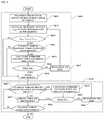
- FIG. 6is a flowchart showing a collision avoidance control method according to an exemplary embodiment of the present invention.
- the collision avoidance control method according to an exemplary embodiment of the present inventionmay be divided into a method in a situation before the host vehicle enters the roundabout (S 610 ) and a method in a situation after the host vehicle enters the roundabout (S 620 ).
- the controller 140may be configured to determine the presence or absence of the roundabout 230 ahead of the host vehicle 210 by applying the current location information of the host vehicle 210 , which is received from the GPS receiver 110 at predetermined time intervals, to the map information extracted from the navigation system 120 (S 611 ) (e.g., the received location information is compared with the extracted map information).
- the controller 140may be configured to calculate a remaining distance L stop between the current location of the host vehicle 210 and the entry boundary line STOP_LINE of the roundabout 230 (S 612 ).
- the controller 140may be configured to determine whether the remaining distance L stop falls within a predetermined region 250 that is spaced apart from the entry boundary line STOP_LINE of the roundabout 230 by a distance equal to or greater than a first distance L min and equal to or less than a second distance L max (S 613 ).
- the first distance L minmay be a minimum margin distance for assuring a safe distance
- the second distance L maxmay be a distance calculated based on the average time required for the controller 140 to determine a risk of collision and establish a driving strategy and based on the speed of the host vehicle 210 .
- the second distance L maxmay be additionally set based on the overall length of the host vehicle 210 .
- the present inventionis not limited thereto.
- the controller 140may be configured to reduce the speed of the host vehicle 210 to a predetermined level or less, and the sensor unit 130 may be configured to sense whether at least one target vehicle 220 is traveling through the roundabout 230 within a predetermined forward range FR of the host vehicle 210 through at least one of the sensors 132 , 134 and 136 (S 614 ).
- the controller 140may be configured to allow the host vehicle 210 to enter the roundabout 230 (S 618 ).
- the controller 140may be configured to calculate an estimated collision point 260 using a point at which the traveling path of the host vehicle 210 and the traveling path of the target vehicle 220 meet or intersect, and may be configured to calculate an arrival time gap
- the controller 140may be configured to determine whether to allow the host vehicle 210 to enter the roundabout 230 by comparing the calculated arrival time gap
- the controller 140may be configured to prohibit the host vehicle 210 from entering the roundabout 230 , and generate a deceleration or stop control command (S 617 ).
- the controller 140may be configured to allow the host vehicle 210 to enter the roundabout 230 (S 618 ).
- the sensor unit 130may be configured to sense whether at least one target vehicle 510 is expected to enter the roundabout 230 within a predetermined forward range FR of the host vehicle 210 through at least one of the sensors 132 , 134 and 136 (S 621 ). When no target vehicle is sensed (NO in S 621 ), the host vehicle 210 may continuously travel through the roundabout 230 (S 625 ).
- the controller 140may be configured to calculate an estimated collision point using a point at which the traveling path of the host vehicle 210 and the traveling path of the target vehicle 510 meet, and may be configured to calculate an arrival time gap
- the controller 140may be configured to determine whether to decelerate or brake the host vehicle 210 traveling through the roundabout 230 by comparing the calculated arrival time gap
- the controller 140may be configured to generate a control command for decelerating or braking the host vehicle 210 traveling through the roundabout 230 (S 624 ).
- the controller 140may be configured to prohibit the host vehicle 210 from decelerating or braking at the roundabout 230 (S 625 ). Thereafter, the controller 140 may be configured to determine whether the host vehicle 210 has exited the roundabout 230 (S 626 ).
- the processmay return to S 621 , where the sensor unit 130 may be configured to sense whether at least one target vehicle 510 is expected to enter the roundabout 230 within a predetermined forward range FR of the host vehicle 210 .
- the collision avoidance control method for traveling through a roundaboutmay be terminated.
- the collision avoidance control methodmay be programmed to be executed in a computer and may be stored on a non-transitory computer-readable recording medium.
- the non-transitory computer-readable recording mediuminclude read-only memory (ROM), random-access memory (RAM), CD-ROMs, magnetic tapes, floppy disks, and optical data storage devices.
- the non-transitory computer-readable recording mediummay also be distributed over network-coupled computer systems so that the computer-readable code is stored and executed in a distributed fashion. Also, functional programs, code, and code segments for accomplishing the above-described method can be easily construed by programmers skilled in the art to which the present disclosure pertains.
- the present inventionprovides a system and method for avoiding a collision when a vehicle enters or travels through a roundabout by determining a risk of collision between the vehicle and other vehicles regardless of support of a V2X network function.
Landscapes
- Engineering & Computer Science (AREA)
- Remote Sensing (AREA)
- Radar, Positioning & Navigation (AREA)
- Physics & Mathematics (AREA)
- General Physics & Mathematics (AREA)
- Mechanical Engineering (AREA)
- Transportation (AREA)
- Automation & Control Theory (AREA)
- Computer Networks & Wireless Communication (AREA)
- Electromagnetism (AREA)
- Mathematical Physics (AREA)
- Chemical & Material Sciences (AREA)
- Combustion & Propulsion (AREA)
- Traffic Control Systems (AREA)
- Control Of Driving Devices And Active Controlling Of Vehicle (AREA)
Abstract
Description
|TGAB-1|=|TA−TB-1|, |TGAB-2|=|TA−TB-2|, |TGAB-3|=|TA−TB-3|, |TGAB-4|=|TA−TB-4|
|TGAB|=min[|TGAB-1|, |TGAB-2|, |TGAB-3|, |TGAB-4|]
Claims (18)
Applications Claiming Priority (2)
| Application Number | Priority Date | Filing Date | Title |
|---|---|---|---|
| KR1020180103547AKR102592825B1 (en) | 2018-08-31 | 2018-08-31 | Control apparatus for avoiding collision and method thereof |
| KR10-2018-0103547 | 2018-08-31 |
Publications (2)
| Publication Number | Publication Date |
|---|---|
| US20200074863A1 US20200074863A1 (en) | 2020-03-05 |
| US11024176B2true US11024176B2 (en) | 2021-06-01 |
Family
ID=69527457
Family Applications (1)
| Application Number | Title | Priority Date | Filing Date |
|---|---|---|---|
| US16/204,329Active2039-08-07US11024176B2 (en) | 2018-08-31 | 2018-11-29 | Collision avoidance control system and method |
Country Status (4)
| Country | Link |
|---|---|
| US (1) | US11024176B2 (en) |
| KR (1) | KR102592825B1 (en) |
| CN (1) | CN110871793B (en) |
| DE (1) | DE102018130995A1 (en) |
Cited By (1)
| Publication number | Priority date | Publication date | Assignee | Title |
|---|---|---|---|---|
| US20230047336A1 (en)* | 2021-08-12 | 2023-02-16 | Waymo Llc | Time gaps for autonomous vehicles |
Families Citing this family (42)
| Publication number | Priority date | Publication date | Assignee | Title |
|---|---|---|---|---|
| US12038765B2 (en) | 2016-08-02 | 2024-07-16 | Transportation Ip Holdings, Llc | Vehicle control system and method |
| WO2018131090A1 (en)* | 2017-01-11 | 2018-07-19 | 本田技研工業株式会社 | Vehicle control device, vehicle control method, and vehicle control program |
| WO2019162717A1 (en)* | 2018-02-20 | 2019-08-29 | 日産自動車株式会社 | Automated lane change control method and automated lane change control device |
| WO2020012210A1 (en)* | 2018-07-11 | 2020-01-16 | 日産自動車株式会社 | Travel assistance method and travel assistance device |
| US10909866B2 (en)* | 2018-07-20 | 2021-02-02 | Cybernet Systems Corp. | Autonomous transportation system and methods |
| US20200211379A1 (en)* | 2018-12-27 | 2020-07-02 | Continental Automotive Systems Inc. | Roundabout assist |
| CN113811932B (en)* | 2019-05-15 | 2023-01-10 | 日产自动车株式会社 | Vehicle travel control method and travel control device |
| US11897468B2 (en)* | 2020-03-03 | 2024-02-13 | Ford Global Technologies, Llc | Vehicle control system |
| CN113442830B (en)* | 2020-03-24 | 2023-07-18 | 荷兰移动驱动器公司 | Traffic safety management and control method, vehicle-mounted device |
| GB202004635D0 (en)* | 2020-03-30 | 2020-05-13 | Five Ai Ltd | Motion predition |
| CN111524389B (en)* | 2020-04-16 | 2023-11-10 | 腾讯科技(深圳)有限公司 | Vehicle driving method and device |
| CN111619561B (en)* | 2020-05-22 | 2022-01-14 | 安徽江淮汽车集团股份有限公司 | Escape lifesaving method, device, equipment and storage medium for automatic driving automobile |
| KR20210149547A (en)* | 2020-06-02 | 2021-12-09 | 현대모비스 주식회사 | Forward collision avoidance system and method of vehicle |
| KR20210153998A (en)* | 2020-06-11 | 2021-12-20 | 현대자동차주식회사 | Vehicle and method for controlling thereof |
| JP7402755B2 (en)* | 2020-06-16 | 2023-12-21 | 日産自動車株式会社 | Observed vehicle state estimation method, host vehicle stop judgment control method, and observed vehicle state estimation device |
| CN111665852B (en)* | 2020-06-30 | 2022-09-06 | 中国第一汽车股份有限公司 | Obstacle avoiding method and device, vehicle and storage medium |
| CN111816004B (en)* | 2020-07-16 | 2024-03-22 | 腾讯科技(深圳)有限公司 | Control method and device for vehicle collision avoidance |
| CN114512027B (en)* | 2020-11-16 | 2023-07-14 | 长城汽车股份有限公司 | Anti-collision control method and device |
| KR20220069520A (en) | 2020-11-20 | 2022-05-27 | 현대모비스 주식회사 | Vehicle driving control system and control method thereof at roundabout |
| KR20220086781A (en) | 2020-12-16 | 2022-06-24 | 현대모비스 주식회사 | Method and system for target detection of vehicle |
| US20210101620A1 (en)* | 2020-12-17 | 2021-04-08 | Intel Corporation | Systems, methods, and devices for generating and using safety threat maps |
| CN112735134B (en)* | 2020-12-30 | 2022-04-19 | 惠州华阳通用电子有限公司 | Multi-lane roundabout entering method for automatically driving vehicle |
| CN113753073B (en)* | 2021-01-12 | 2024-07-16 | 京东鲲鹏(江苏)科技有限公司 | Vehicle speed control method, device, equipment and storage medium |
| KR102811066B1 (en)* | 2021-04-28 | 2025-05-23 | 주식회사 에이치엘클레무브 | Apparatus for assisting driving of a host vehicle andmethod thereof |
| CN113327457B (en)* | 2021-06-04 | 2022-03-29 | 中山大学 | Vehicle collision avoidance system and method based on vehicle-road cooperation technology |
| CN113401138B (en)* | 2021-06-18 | 2022-05-03 | 清华大学 | A method, apparatus and system for calculating potential collision severity index |
| WO2022266858A1 (en)* | 2021-06-22 | 2022-12-29 | 华为技术有限公司 | Blind area detection method and device |
| CN113554870A (en)* | 2021-07-16 | 2021-10-26 | 中国联合网络通信集团有限公司 | Road traffic early warning method, system, terminal equipment and storage medium around the island |
| CN116189472B (en)* | 2021-11-26 | 2025-09-05 | 上海汽车集团股份有限公司 | A road intersection warning method and device |
| CN114137980B (en)* | 2021-11-29 | 2022-12-13 | 广州小鹏自动驾驶科技有限公司 | Control method and device, vehicle and readable storage medium |
| CN115035745B (en)* | 2022-05-30 | 2024-03-01 | 北京京东乾石科技有限公司 | Car following control method and device for avoiding cluster collision, electronic equipment and storage medium |
| FR3136432A1 (en)* | 2022-06-14 | 2023-12-15 | Psa Automobiles Sa | Methods and systems for assisting the driving of a motor vehicle when approaching an intersection with priority |
| CN115071696A (en)* | 2022-06-20 | 2022-09-20 | 重庆理工大学 | Automatic emergency collision avoidance control method for intelligent automobile intersection based on V2X |
| CN115195716B (en)* | 2022-07-04 | 2025-02-07 | 中国联合网络通信集团有限公司 | Vehicle control method, device, storage medium and equipment |
| CN115083209B (en)* | 2022-07-26 | 2022-11-04 | 广州市德赛西威智慧交通技术有限公司 | Vehicle-road cooperation method and system based on visual positioning |
| CN115472005B (en)* | 2022-08-09 | 2023-12-19 | 东软睿驰汽车技术(上海)有限公司 | Vehicle collision early warning method, device, equipment and storage medium |
| JP7616183B2 (en)* | 2022-09-22 | 2025-01-17 | トヨタ自動車株式会社 | Travel plan creation device, travel plan creation method, and travel plan creation computer program |
| TWI830415B (en)* | 2022-09-30 | 2024-01-21 | 荷蘭商荷蘭移動驅動器公司 | Method and device for collision predicting and readable computer storage media |
| WO2024127463A1 (en)* | 2022-12-12 | 2024-06-20 | 日立Astemo株式会社 | Traffic flow control system |
| GB202308270D0 (en)* | 2023-06-02 | 2023-07-19 | Five Ai Ltd | Trajectory evaluation for mobile robots |
| CN117636664B (en)* | 2023-11-27 | 2025-03-25 | 东风汽车集团股份有限公司 | Vehicle dispatching method and system at intersection without signal lights |
| CN117949995B (en)* | 2024-03-26 | 2024-06-28 | 徐州众图智控通信科技有限公司 | Coal mine vehicle positioning monitoring method and system based on range radar |
Citations (65)
| Publication number | Priority date | Publication date | Assignee | Title |
|---|---|---|---|---|
| US5572428A (en)* | 1993-09-30 | 1996-11-05 | Honda Giken Kogyo Kabushiki Kaisha | Anti-collision system for vehicles |
| US6067031A (en)* | 1997-12-18 | 2000-05-23 | Trimble Navigation Limited | Dynamic monitoring of vehicle separation |
| US6084508A (en)* | 1997-07-17 | 2000-07-04 | Volkswagen Ag | Automatic emergency braking method and arrangement |
| US20020097170A1 (en)* | 2000-06-30 | 2002-07-25 | Nobuhiko Yasui | Rendering device |
| US6445308B1 (en)* | 1999-01-12 | 2002-09-03 | Toyota Jidosha Kabushiki Kaisha | Positional data utilizing inter-vehicle communication method and traveling control apparatus |
| US20030016143A1 (en)* | 2001-07-23 | 2003-01-23 | Ohanes Ghazarian | Intersection vehicle collision avoidance system |
| US20040019420A1 (en)* | 2002-07-23 | 2004-01-29 | Rao Manoharprasad K. | Method for determining a danger zone for a pre-crash sensing system in a vehicle having a countermeasure system |
| US7145441B2 (en)* | 2002-09-23 | 2006-12-05 | Robert Bosch Gmbh | Method and device for preventing collision of vehicles |
| US20060274149A1 (en)* | 2005-05-13 | 2006-12-07 | Honda Motor Co., Ltd. | Apparatus and method for predicting collision |
| US20070005609A1 (en)* | 1997-10-22 | 2007-01-04 | Intelligent Technologies International, Inc. | Vehicular Communication Arrangement and Method |
| US7209051B2 (en)* | 2002-03-05 | 2007-04-24 | University Of Minnesota | Intersection assistance system and method |
| US7409295B2 (en)* | 2004-08-09 | 2008-08-05 | M/A-Com, Inc. | Imminent-collision detection system and process |
| US20080306666A1 (en)* | 2007-06-05 | 2008-12-11 | Gm Global Technology Operations, Inc. | Method and apparatus for rear cross traffic collision avoidance |
| US20090143951A1 (en)* | 2007-11-16 | 2009-06-04 | Hitachi, Ltd. | Forward Collision Avoidance Assistance System |
| US20100185411A1 (en)* | 2009-01-16 | 2010-07-22 | Randall Richard Pfeiffer | Object monitor |
| US20110082623A1 (en)* | 2009-10-05 | 2011-04-07 | Jianbo Lu | System for vehicle control to mitigate intersection collisions and method of using the same |
| US20110298603A1 (en)* | 2006-03-06 | 2011-12-08 | King Timothy I | Intersection Collision Warning System |
| US20110301845A1 (en)* | 2009-01-29 | 2011-12-08 | Toyota Jidosha Kabushiki Kaisha | Object recognition device and object recognition method |
| US20110313665A1 (en)* | 2009-03-04 | 2011-12-22 | Adc Automotive Distance Control Systems Gmbh | Method for Automatically Detecting a Driving Maneuver of a Motor Vehicle and a Driver Assistance System Comprising Said Method |
| US20120035846A1 (en)* | 2009-04-14 | 2012-02-09 | Hiroshi Sakamoto | External environment recognition device for vehicle and vehicle system using same |
| US8250695B2 (en)* | 2009-10-05 | 2012-08-28 | Applied Materials, Inc. | Roller assembly for a brush cleaning device in a cleaning module |
| US20130279491A1 (en)* | 2012-04-24 | 2013-10-24 | Zetta Research And Development Llc - Forc Series | Hybrid protocol transceiver for v2v communication |
| US20140032049A1 (en)* | 2012-07-24 | 2014-01-30 | GM Global Technology Operations LLC | Steering Assist in Driver Initiated Collision Avoidance Maneuver |
| KR101414571B1 (en)* | 2013-02-18 | 2014-08-06 | 주식회사 만도 | Apparatus of preventing collision in vehicle, control method of thereof |
| US20140303882A1 (en)* | 2013-04-05 | 2014-10-09 | Electronics And Telecommunications Research Institute | Apparatus and method for providing intersection collision-related information |
| US8860564B2 (en)* | 2012-04-24 | 2014-10-14 | Zetta Research and Development, ForC Series | Risk management in a vehicle anti-collision system |
| US20140324286A1 (en)* | 2013-04-26 | 2014-10-30 | Denso Corporation | Vehicle-use collision mitigation apparatus |
| US20140347207A1 (en)* | 2013-05-23 | 2014-11-27 | GM Global Technology Operations LLC | Probabilistic target selection and threat assessment method and application to intersection collision alert system |
| US9187091B2 (en)* | 2012-07-30 | 2015-11-17 | Ford Global Technologies, Llc | Collision detection system with a plausibiity module |
| US20150353078A1 (en)* | 2014-06-04 | 2015-12-10 | Toyota Jidosha Kabushiki Kaisha | Driving assistance apparatus |
| US20160016561A1 (en)* | 2014-07-16 | 2016-01-21 | Mando Corporation | Emergency braking system for protecting moving object and method for controlling the same |
| US20160091897A1 (en)* | 2014-09-26 | 2016-03-31 | Volvo Car Corporation | Method of trajectory planning for yielding maneuvers |
| US20160362104A1 (en)* | 2015-06-10 | 2016-12-15 | Ford Global Technologies, Llc | Collision mitigation and avoidance |
| US20160368492A1 (en)* | 2015-06-16 | 2016-12-22 | Honda Motor Co., Ltd. | System and method for providing vehicle collision avoidance at an intersection |
| US20170113665A1 (en)* | 2015-10-27 | 2017-04-27 | GM Global Technology Operations LLC | Algorithms for avoiding automotive crashes at left and right turn intersections |
| US9650040B2 (en)* | 2013-05-14 | 2017-05-16 | Denso Corporation | Collision mitigation apparatus |
| US20170154531A1 (en)* | 2015-11-30 | 2017-06-01 | Denso Corporation | Drive support apparatus |
| US9691282B2 (en)* | 2011-03-04 | 2017-06-27 | Continental Teves Ag & Co. Ohg | Limiting the activation of an emergency steer assistant |
| US9738315B2 (en)* | 2015-10-05 | 2017-08-22 | Hyundai Motor Company | Parking guidance apparatus and method for vehicle |
| US9784831B2 (en)* | 2014-08-20 | 2017-10-10 | Wistron Neweb Corporation | Pre-warning method and vehicle radar system |
| US9798011B2 (en)* | 2012-08-31 | 2017-10-24 | Apple Inc. | Fast GPS recovery using map vector data |
| US20170330464A1 (en)* | 2016-05-12 | 2017-11-16 | Lg Electronics Inc. | Control Device Mounted On Vehicle And Method For Controlling The Same |
| US20180151073A1 (en)* | 2015-05-27 | 2018-05-31 | Denso Corporation | Vehicle control device and vehicle control method |
| US20180178722A1 (en)* | 2016-12-26 | 2018-06-28 | Toyota Jidosha Kabushiki Kaisha | In-vehicle alert apparatus |
| US10011277B2 (en)* | 2016-06-02 | 2018-07-03 | Ford Global Technologies, Llc | Vehicle collision avoidance |
| US20180251092A1 (en)* | 2017-03-06 | 2018-09-06 | GM Global Technology Operations LLC | Vehicle collision prediction algorithm using radar sensor and upa sensor |
| US20180261094A1 (en)* | 2017-03-13 | 2018-09-13 | Toyota Jidosha Kabushiki Kaisha | Collision preventing control device |
| US20180268227A1 (en)* | 2017-03-14 | 2018-09-20 | Toyota Jidosha Kabushiki Kaisha | Image recording system, image recording method and image recording program |
| US20180284791A1 (en)* | 2017-03-31 | 2018-10-04 | Panasonic Intellectual Property Management Co., Ltd. | Automatic driving control method, automatic driving control device using the same, and non-transitory storage medium |
| US20180304889A1 (en)* | 2016-01-05 | 2018-10-25 | Mobileye Vision Technologies Ltd. | Navigating a vehicle based on predictive aggression of other vehicle |
| US20180339670A1 (en)* | 2017-05-24 | 2018-11-29 | Toyota Jidosha Kabushiki Kaisha | Collision preventing control device |
| US20180354555A1 (en)* | 2017-06-12 | 2018-12-13 | Steering Solutions Ip Holding Corporation | Vehicle safety steering system |
| US20190092343A1 (en)* | 2017-09-25 | 2019-03-28 | Toyota Jidosha Kabushiki Kaisha | Driving support device |
| US10268909B2 (en)* | 2016-09-14 | 2019-04-23 | Nauto, Inc. | Systems and methods for near-crash determination |
| US10266175B2 (en)* | 2016-05-31 | 2019-04-23 | Ford Global Technologies, Llc | Vehicle collision avoidance |
| US20190152523A1 (en)* | 2017-11-17 | 2019-05-23 | Subaru Corporation | Lane deviation prevention control device for vehicle |
| US20190256144A1 (en)* | 2018-02-16 | 2019-08-22 | Toyota Jidosha Kabushiki Kaisha | Parking assist apparatus |
| US10403145B2 (en)* | 2017-01-19 | 2019-09-03 | Ford Global Technologies, Llc | Collison mitigation and avoidance |
| US10486707B2 (en)* | 2016-01-06 | 2019-11-26 | GM Global Technology Operations LLC | Prediction of driver intent at intersection |
| US20200005645A1 (en)* | 2018-06-29 | 2020-01-02 | Nissan North America, Inc. | Orientation-Adjust Actions for Autonomous Vehicle Operational Management |
| US20200073977A1 (en)* | 2018-08-31 | 2020-03-05 | Waymo Llc | Validating road intersections |
| US20200086855A1 (en)* | 2018-09-19 | 2020-03-19 | Zoox, Inc. | Collision prediction and avoidance for vehicles |
| US20200118441A1 (en)* | 2018-10-10 | 2020-04-16 | Hyundai Motor Company | Apparatus and method for identifying close cut-in vehicle and vehicle including apparatus |
| US20200249674A1 (en)* | 2019-02-05 | 2020-08-06 | Nvidia Corporation | Combined prediction and path planning for autonomous objects using neural networks |
| US20200255001A1 (en)* | 2019-02-11 | 2020-08-13 | Ford Global Technologies, Llc | Enhanced collision mitigation |
Family Cites Families (10)
| Publication number | Priority date | Publication date | Assignee | Title |
|---|---|---|---|---|
| JP4762610B2 (en)* | 2005-06-14 | 2011-08-31 | 本田技研工業株式会社 | Vehicle travel safety device |
| US8706393B2 (en)* | 2012-01-10 | 2014-04-22 | Ford Global Technologies, Llc | Intersection collision avoidance with adaptable vehicle dimensions |
| CN103879404B (en)* | 2012-12-19 | 2016-08-31 | 财团法人车辆研究测试中心 | Anti-collision warning method and device capable of tracking moving objects |
| DE202013006676U1 (en)* | 2013-07-25 | 2014-10-28 | GM Global Technology Operations LLC (n. d. Ges. d. Staates Delaware) | System for warning of a possible collision of a motor vehicle with an object |
| DE102014008897A1 (en)* | 2014-06-14 | 2015-12-17 | Audi Ag | Method for determining an expected time for a collision between a first motor vehicle and a second motor vehicle and associated motor vehicle |
| DE102016210848A1 (en)* | 2015-07-06 | 2017-01-12 | Ford Global Technologies, Llc | Method for avoiding a collision of a vehicle with an object, and driving assistance system |
| DE102016000943B4 (en)* | 2016-01-28 | 2023-09-07 | Zf Automotive Germany Gmbh | Control system and control method for determining a probability of an impending collision of a vehicle |
| KR102441050B1 (en)* | 2016-07-20 | 2022-09-06 | 현대자동차주식회사 | Vehicle collision control device and method |
| KR101979269B1 (en)* | 2016-10-28 | 2019-05-16 | 엘지전자 주식회사 | Autonomous Vehicle and operating method for the same |
| KR102406506B1 (en)* | 2017-02-17 | 2022-06-10 | 현대자동차주식회사 | Apparatus for controlling competition of an autonomous vehicle, system having the same and method thereof |
- 2018
- 2018-08-31KRKR1020180103547Apatent/KR102592825B1/enactiveActive
- 2018-11-29USUS16/204,329patent/US11024176B2/enactiveActive
- 2018-12-05DEDE102018130995.3Apatent/DE102018130995A1/enactivePending
- 2018-12-07CNCN201811496704.7Apatent/CN110871793B/enactiveActive
Patent Citations (69)
| Publication number | Priority date | Publication date | Assignee | Title |
|---|---|---|---|---|
| US5572428A (en)* | 1993-09-30 | 1996-11-05 | Honda Giken Kogyo Kabushiki Kaisha | Anti-collision system for vehicles |
| US6084508A (en)* | 1997-07-17 | 2000-07-04 | Volkswagen Ag | Automatic emergency braking method and arrangement |
| US20070005609A1 (en)* | 1997-10-22 | 2007-01-04 | Intelligent Technologies International, Inc. | Vehicular Communication Arrangement and Method |
| US6067031A (en)* | 1997-12-18 | 2000-05-23 | Trimble Navigation Limited | Dynamic monitoring of vehicle separation |
| US6445308B1 (en)* | 1999-01-12 | 2002-09-03 | Toyota Jidosha Kabushiki Kaisha | Positional data utilizing inter-vehicle communication method and traveling control apparatus |
| US20020097170A1 (en)* | 2000-06-30 | 2002-07-25 | Nobuhiko Yasui | Rendering device |
| US20030016143A1 (en)* | 2001-07-23 | 2003-01-23 | Ohanes Ghazarian | Intersection vehicle collision avoidance system |
| US7209051B2 (en)* | 2002-03-05 | 2007-04-24 | University Of Minnesota | Intersection assistance system and method |
| US20040019420A1 (en)* | 2002-07-23 | 2004-01-29 | Rao Manoharprasad K. | Method for determining a danger zone for a pre-crash sensing system in a vehicle having a countermeasure system |
| US7145441B2 (en)* | 2002-09-23 | 2006-12-05 | Robert Bosch Gmbh | Method and device for preventing collision of vehicles |
| US7409295B2 (en)* | 2004-08-09 | 2008-08-05 | M/A-Com, Inc. | Imminent-collision detection system and process |
| US20060274149A1 (en)* | 2005-05-13 | 2006-12-07 | Honda Motor Co., Ltd. | Apparatus and method for predicting collision |
| US20110298603A1 (en)* | 2006-03-06 | 2011-12-08 | King Timothy I | Intersection Collision Warning System |
| US20080306666A1 (en)* | 2007-06-05 | 2008-12-11 | Gm Global Technology Operations, Inc. | Method and apparatus for rear cross traffic collision avoidance |
| US20090143951A1 (en)* | 2007-11-16 | 2009-06-04 | Hitachi, Ltd. | Forward Collision Avoidance Assistance System |
| US20100185411A1 (en)* | 2009-01-16 | 2010-07-22 | Randall Richard Pfeiffer | Object monitor |
| US8818703B2 (en)* | 2009-01-29 | 2014-08-26 | Toyota Jidosha Kabushiki Kaisha | Object recognition device and object recognition method |
| US20110301845A1 (en)* | 2009-01-29 | 2011-12-08 | Toyota Jidosha Kabushiki Kaisha | Object recognition device and object recognition method |
| US20110313665A1 (en)* | 2009-03-04 | 2011-12-22 | Adc Automotive Distance Control Systems Gmbh | Method for Automatically Detecting a Driving Maneuver of a Motor Vehicle and a Driver Assistance System Comprising Said Method |
| US20120035846A1 (en)* | 2009-04-14 | 2012-02-09 | Hiroshi Sakamoto | External environment recognition device for vehicle and vehicle system using same |
| US8250695B2 (en)* | 2009-10-05 | 2012-08-28 | Applied Materials, Inc. | Roller assembly for a brush cleaning device in a cleaning module |
| US8577550B2 (en)* | 2009-10-05 | 2013-11-05 | Ford Global Technologies, Llc | System for vehicle control to mitigate intersection collisions and method of using the same |
| US20110082623A1 (en)* | 2009-10-05 | 2011-04-07 | Jianbo Lu | System for vehicle control to mitigate intersection collisions and method of using the same |
| US9691282B2 (en)* | 2011-03-04 | 2017-06-27 | Continental Teves Ag & Co. Ohg | Limiting the activation of an emergency steer assistant |
| US8860564B2 (en)* | 2012-04-24 | 2014-10-14 | Zetta Research and Development, ForC Series | Risk management in a vehicle anti-collision system |
| US20130279491A1 (en)* | 2012-04-24 | 2013-10-24 | Zetta Research And Development Llc - Forc Series | Hybrid protocol transceiver for v2v communication |
| US20140032049A1 (en)* | 2012-07-24 | 2014-01-30 | GM Global Technology Operations LLC | Steering Assist in Driver Initiated Collision Avoidance Maneuver |
| US9187091B2 (en)* | 2012-07-30 | 2015-11-17 | Ford Global Technologies, Llc | Collision detection system with a plausibiity module |
| US9798011B2 (en)* | 2012-08-31 | 2017-10-24 | Apple Inc. | Fast GPS recovery using map vector data |
| KR101414571B1 (en)* | 2013-02-18 | 2014-08-06 | 주식회사 만도 | Apparatus of preventing collision in vehicle, control method of thereof |
| US20140303882A1 (en)* | 2013-04-05 | 2014-10-09 | Electronics And Telecommunications Research Institute | Apparatus and method for providing intersection collision-related information |
| US20140324286A1 (en)* | 2013-04-26 | 2014-10-30 | Denso Corporation | Vehicle-use collision mitigation apparatus |
| US9650040B2 (en)* | 2013-05-14 | 2017-05-16 | Denso Corporation | Collision mitigation apparatus |
| US20140347207A1 (en)* | 2013-05-23 | 2014-11-27 | GM Global Technology Operations LLC | Probabilistic target selection and threat assessment method and application to intersection collision alert system |
| US20150353078A1 (en)* | 2014-06-04 | 2015-12-10 | Toyota Jidosha Kabushiki Kaisha | Driving assistance apparatus |
| US20160016561A1 (en)* | 2014-07-16 | 2016-01-21 | Mando Corporation | Emergency braking system for protecting moving object and method for controlling the same |
| US9784831B2 (en)* | 2014-08-20 | 2017-10-10 | Wistron Neweb Corporation | Pre-warning method and vehicle radar system |
| US10268197B2 (en)* | 2014-09-26 | 2019-04-23 | Volvo Car Corporation | Method of trajectory planning for yielding maneuvers |
| US20160091897A1 (en)* | 2014-09-26 | 2016-03-31 | Volvo Car Corporation | Method of trajectory planning for yielding maneuvers |
| US20180151073A1 (en)* | 2015-05-27 | 2018-05-31 | Denso Corporation | Vehicle control device and vehicle control method |
| US20160362104A1 (en)* | 2015-06-10 | 2016-12-15 | Ford Global Technologies, Llc | Collision mitigation and avoidance |
| US20160368492A1 (en)* | 2015-06-16 | 2016-12-22 | Honda Motor Co., Ltd. | System and method for providing vehicle collision avoidance at an intersection |
| US9738315B2 (en)* | 2015-10-05 | 2017-08-22 | Hyundai Motor Company | Parking guidance apparatus and method for vehicle |
| US20170113665A1 (en)* | 2015-10-27 | 2017-04-27 | GM Global Technology Operations LLC | Algorithms for avoiding automotive crashes at left and right turn intersections |
| US20170154531A1 (en)* | 2015-11-30 | 2017-06-01 | Denso Corporation | Drive support apparatus |
| US20180304889A1 (en)* | 2016-01-05 | 2018-10-25 | Mobileye Vision Technologies Ltd. | Navigating a vehicle based on predictive aggression of other vehicle |
| US10486707B2 (en)* | 2016-01-06 | 2019-11-26 | GM Global Technology Operations LLC | Prediction of driver intent at intersection |
| US20170330464A1 (en)* | 2016-05-12 | 2017-11-16 | Lg Electronics Inc. | Control Device Mounted On Vehicle And Method For Controlling The Same |
| US10266175B2 (en)* | 2016-05-31 | 2019-04-23 | Ford Global Technologies, Llc | Vehicle collision avoidance |
| US10011277B2 (en)* | 2016-06-02 | 2018-07-03 | Ford Global Technologies, Llc | Vehicle collision avoidance |
| US10268909B2 (en)* | 2016-09-14 | 2019-04-23 | Nauto, Inc. | Systems and methods for near-crash determination |
| US20180178722A1 (en)* | 2016-12-26 | 2018-06-28 | Toyota Jidosha Kabushiki Kaisha | In-vehicle alert apparatus |
| US10403145B2 (en)* | 2017-01-19 | 2019-09-03 | Ford Global Technologies, Llc | Collison mitigation and avoidance |
| US20180251092A1 (en)* | 2017-03-06 | 2018-09-06 | GM Global Technology Operations LLC | Vehicle collision prediction algorithm using radar sensor and upa sensor |
| US20180261094A1 (en)* | 2017-03-13 | 2018-09-13 | Toyota Jidosha Kabushiki Kaisha | Collision preventing control device |
| US20180268227A1 (en)* | 2017-03-14 | 2018-09-20 | Toyota Jidosha Kabushiki Kaisha | Image recording system, image recording method and image recording program |
| US20180284791A1 (en)* | 2017-03-31 | 2018-10-04 | Panasonic Intellectual Property Management Co., Ltd. | Automatic driving control method, automatic driving control device using the same, and non-transitory storage medium |
| US20180339670A1 (en)* | 2017-05-24 | 2018-11-29 | Toyota Jidosha Kabushiki Kaisha | Collision preventing control device |
| US20180354555A1 (en)* | 2017-06-12 | 2018-12-13 | Steering Solutions Ip Holding Corporation | Vehicle safety steering system |
| US20190092343A1 (en)* | 2017-09-25 | 2019-03-28 | Toyota Jidosha Kabushiki Kaisha | Driving support device |
| US20190152523A1 (en)* | 2017-11-17 | 2019-05-23 | Subaru Corporation | Lane deviation prevention control device for vehicle |
| US20190256144A1 (en)* | 2018-02-16 | 2019-08-22 | Toyota Jidosha Kabushiki Kaisha | Parking assist apparatus |
| US20200005645A1 (en)* | 2018-06-29 | 2020-01-02 | Nissan North America, Inc. | Orientation-Adjust Actions for Autonomous Vehicle Operational Management |
| US20200073977A1 (en)* | 2018-08-31 | 2020-03-05 | Waymo Llc | Validating road intersections |
| US20200086855A1 (en)* | 2018-09-19 | 2020-03-19 | Zoox, Inc. | Collision prediction and avoidance for vehicles |
| US20200118441A1 (en)* | 2018-10-10 | 2020-04-16 | Hyundai Motor Company | Apparatus and method for identifying close cut-in vehicle and vehicle including apparatus |
| US10818184B2 (en)* | 2018-10-10 | 2020-10-27 | Hyundai Motor Company | Apparatus and method for identifying close cut-in vehicle and vehicle including apparatus |
| US20200249674A1 (en)* | 2019-02-05 | 2020-08-06 | Nvidia Corporation | Combined prediction and path planning for autonomous objects using neural networks |
| US20200255001A1 (en)* | 2019-02-11 | 2020-08-13 | Ford Global Technologies, Llc | Enhanced collision mitigation |
Cited By (2)
| Publication number | Priority date | Publication date | Assignee | Title |
|---|---|---|---|---|
| US20230047336A1 (en)* | 2021-08-12 | 2023-02-16 | Waymo Llc | Time gaps for autonomous vehicles |
| US12252158B2 (en)* | 2021-08-12 | 2025-03-18 | Waymo Llc | Time gaps for autonomous vehicles |
Also Published As
| Publication number | Publication date |
|---|---|
| CN110871793A (en) | 2020-03-10 |
| KR20200025730A (en) | 2020-03-10 |
| US20200074863A1 (en) | 2020-03-05 |
| KR102592825B1 (en) | 2023-10-23 |
| CN110871793B (en) | 2024-08-06 |
| DE102018130995A1 (en) | 2020-03-05 |
Similar Documents
| Publication | Publication Date | Title |
|---|---|---|
| US11024176B2 (en) | Collision avoidance control system and method | |
| CN112810628B (en) | Vehicle Control Systems | |
| JP7207256B2 (en) | vehicle control system | |
| US20190016339A1 (en) | Vehicle control device, vehicle control method, and vehicle control program | |
| US20180056997A1 (en) | Vehicle control device | |
| US11059481B2 (en) | Vehicle control system, vehicle control method, and vehicle control program | |
| US10532736B2 (en) | Vehicle travel control device | |
| CN116872921A (en) | Method and system for avoiding risks of vehicle, vehicle and storage medium | |
| US11608062B2 (en) | Vehicle control method and vehicle control device | |
| US20210163039A1 (en) | Vehicle control system and vehicle control method | |
| CN111506084B (en) | Obstacle avoidance method, apparatus, device and storage medium for unmanned vehicle | |
| KR20180096463A (en) | System and method for vulnerable road user collision prevention | |
| JPWO2017126250A1 (en) | Driving support method and apparatus | |
| US11042160B2 (en) | Autonomous driving trajectory determination device | |
| US20190308618A1 (en) | Driving support apparatus | |
| US12036978B2 (en) | Driving assistance method and driving assistance device | |
| JP5565303B2 (en) | Driving support device and driving support method | |
| US20200398864A1 (en) | Vehicle-Behavior Prediction Method and Vehicle-Behavior Prediction Device | |
| CN111717212B (en) | Following control method and device for automatic driving vehicle | |
| CN111717213A (en) | Cruise control method and device for automatic driving vehicle | |
| US20240010193A1 (en) | Vehicle control apparatus | |
| JP2020192942A (en) | Traveling support method and traveling support device | |
| JP2019214291A (en) | Travel support method and travel support device | |
| KR102816596B1 (en) | Methods for providing risk-minimizing behavior considering traffic and vehicle and road systems supporting the same method | |
| US20250108797A1 (en) | Driving assistance device, driving assistance method, and storage medium |
Legal Events
| Date | Code | Title | Description |
|---|---|---|---|
| AS | Assignment | Owner name:KIA MOTORS CORPORATION, KOREA, REPUBLIC OF Free format text:ASSIGNMENT OF ASSIGNORS INTEREST;ASSIGNORS:JUNG, CHANG YOUNG;KIM, BYOUNG KWANG;KWON, SU RIM;REEL/FRAME:047625/0638 Effective date:20181122 Owner name:HYUNDAI MOTOR COMPANY, KOREA, REPUBLIC OF Free format text:ASSIGNMENT OF ASSIGNORS INTEREST;ASSIGNORS:JUNG, CHANG YOUNG;KIM, BYOUNG KWANG;KWON, SU RIM;REEL/FRAME:047625/0638 Effective date:20181122 | |
| FEPP | Fee payment procedure | Free format text:ENTITY STATUS SET TO UNDISCOUNTED (ORIGINAL EVENT CODE: BIG.); ENTITY STATUS OF PATENT OWNER: LARGE ENTITY | |
| STPP | Information on status: patent application and granting procedure in general | Free format text:NOTICE OF ALLOWANCE MAILED -- APPLICATION RECEIVED IN OFFICE OF PUBLICATIONS | |
| STPP | Information on status: patent application and granting procedure in general | Free format text:PUBLICATIONS -- ISSUE FEE PAYMENT RECEIVED | |
| STPP | Information on status: patent application and granting procedure in general | Free format text:PUBLICATIONS -- ISSUE FEE PAYMENT VERIFIED | |
| STCF | Information on status: patent grant | Free format text:PATENTED CASE | |
| MAFP | Maintenance fee payment | Free format text:PAYMENT OF MAINTENANCE FEE, 4TH YEAR, LARGE ENTITY (ORIGINAL EVENT CODE: M1551); ENTITY STATUS OF PATENT OWNER: LARGE ENTITY Year of fee payment:4 |