US11024051B2 - Object detection device - Google Patents
Object detection deviceDownload PDFInfo
- Publication number
- US11024051B2 US11024051B2US16/346,029US201716346029AUS11024051B2US 11024051 B2US11024051 B2US 11024051B2US 201716346029 AUS201716346029 AUS 201716346029AUS 11024051 B2US11024051 B2US 11024051B2
- Authority
- US
- United States
- Prior art keywords
- road surface
- disparity
- ground
- data
- shoulder
- Prior art date
- Legal status (The legal status is an assumption and is not a legal conclusion. Google has not performed a legal analysis and makes no representation as to the accuracy of the status listed.)
- Active, expires
Links
Images


Classifications
- G—PHYSICS
- G06—COMPUTING OR CALCULATING; COUNTING
- G06T—IMAGE DATA PROCESSING OR GENERATION, IN GENERAL
- G06T7/00—Image analysis
- G06T7/50—Depth or shape recovery
- G06T7/55—Depth or shape recovery from multiple images
- G06T7/593—Depth or shape recovery from multiple images from stereo images
- G—PHYSICS
- G06—COMPUTING OR CALCULATING; COUNTING
- G06T—IMAGE DATA PROCESSING OR GENERATION, IN GENERAL
- G06T7/00—Image analysis
- G06T7/70—Determining position or orientation of objects or cameras
- G—PHYSICS
- G01—MEASURING; TESTING
- G01C—MEASURING DISTANCES, LEVELS OR BEARINGS; SURVEYING; NAVIGATION; GYROSCOPIC INSTRUMENTS; PHOTOGRAMMETRY OR VIDEOGRAMMETRY
- G01C3/00—Measuring distances in line of sight; Optical rangefinders
- G01C3/02—Details
- G01C3/06—Use of electric means to obtain final indication
- G06K9/00798—
- G06K9/00805—
- G—PHYSICS
- G06—COMPUTING OR CALCULATING; COUNTING
- G06T—IMAGE DATA PROCESSING OR GENERATION, IN GENERAL
- G06T1/00—General purpose image data processing
- G—PHYSICS
- G06—COMPUTING OR CALCULATING; COUNTING
- G06T—IMAGE DATA PROCESSING OR GENERATION, IN GENERAL
- G06T7/00—Image analysis
- G—PHYSICS
- G06—COMPUTING OR CALCULATING; COUNTING
- G06T—IMAGE DATA PROCESSING OR GENERATION, IN GENERAL
- G06T7/00—Image analysis
- G06T7/10—Segmentation; Edge detection
- G06T7/12—Edge-based segmentation
- G—PHYSICS
- G06—COMPUTING OR CALCULATING; COUNTING
- G06T—IMAGE DATA PROCESSING OR GENERATION, IN GENERAL
- G06T7/00—Image analysis
- G06T7/60—Analysis of geometric attributes
- G—PHYSICS
- G06—COMPUTING OR CALCULATING; COUNTING
- G06T—IMAGE DATA PROCESSING OR GENERATION, IN GENERAL
- G06T7/00—Image analysis
- G06T7/70—Determining position or orientation of objects or cameras
- G06T7/73—Determining position or orientation of objects or cameras using feature-based methods
- G—PHYSICS
- G06—COMPUTING OR CALCULATING; COUNTING
- G06V—IMAGE OR VIDEO RECOGNITION OR UNDERSTANDING
- G06V20/00—Scenes; Scene-specific elements
- G06V20/50—Context or environment of the image
- G06V20/56—Context or environment of the image exterior to a vehicle by using sensors mounted on the vehicle
- G06V20/58—Recognition of moving objects or obstacles, e.g. vehicles or pedestrians; Recognition of traffic objects, e.g. traffic signs, traffic lights or roads
- G—PHYSICS
- G06—COMPUTING OR CALCULATING; COUNTING
- G06V—IMAGE OR VIDEO RECOGNITION OR UNDERSTANDING
- G06V20/00—Scenes; Scene-specific elements
- G06V20/50—Context or environment of the image
- G06V20/56—Context or environment of the image exterior to a vehicle by using sensors mounted on the vehicle
- G06V20/588—Recognition of the road, e.g. of lane markings; Recognition of the vehicle driving pattern in relation to the road
- G—PHYSICS
- G08—SIGNALLING
- G08G—TRAFFIC CONTROL SYSTEMS
- G08G1/00—Traffic control systems for road vehicles
- G08G1/16—Anti-collision systems
- H—ELECTRICITY
- H04—ELECTRIC COMMUNICATION TECHNIQUE
- H04N—PICTORIAL COMMUNICATION, e.g. TELEVISION
- H04N7/00—Television systems
- H04N7/18—Closed-circuit television [CCTV] systems, i.e. systems in which the video signal is not broadcast
- H—ELECTRICITY
- H04—ELECTRIC COMMUNICATION TECHNIQUE
- H04N—PICTORIAL COMMUNICATION, e.g. TELEVISION
- H04N7/00—Television systems
- H04N7/18—Closed-circuit television [CCTV] systems, i.e. systems in which the video signal is not broadcast
- H04N7/183—Closed-circuit television [CCTV] systems, i.e. systems in which the video signal is not broadcast for receiving images from a single remote source
- G—PHYSICS
- G06—COMPUTING OR CALCULATING; COUNTING
- G06T—IMAGE DATA PROCESSING OR GENERATION, IN GENERAL
- G06T2200/00—Indexing scheme for image data processing or generation, in general
- G06T2200/04—Indexing scheme for image data processing or generation, in general involving 3D image data
- G—PHYSICS
- G06—COMPUTING OR CALCULATING; COUNTING
- G06T—IMAGE DATA PROCESSING OR GENERATION, IN GENERAL
- G06T2207/00—Indexing scheme for image analysis or image enhancement
- G06T2207/10—Image acquisition modality
- G06T2207/10004—Still image; Photographic image
- G06T2207/10012—Stereo images
- G—PHYSICS
- G06—COMPUTING OR CALCULATING; COUNTING
- G06T—IMAGE DATA PROCESSING OR GENERATION, IN GENERAL
- G06T2207/00—Indexing scheme for image analysis or image enhancement
- G06T2207/20—Special algorithmic details
- G06T2207/20228—Disparity calculation for image-based rendering
- G—PHYSICS
- G06—COMPUTING OR CALCULATING; COUNTING
- G06T—IMAGE DATA PROCESSING OR GENERATION, IN GENERAL
- G06T2207/00—Indexing scheme for image analysis or image enhancement
- G06T2207/30—Subject of image; Context of image processing
- G06T2207/30248—Vehicle exterior or interior
- G06T2207/30252—Vehicle exterior; Vicinity of vehicle
- G06T2207/30256—Lane; Road marking
- G—PHYSICS
- G06—COMPUTING OR CALCULATING; COUNTING
- G06T—IMAGE DATA PROCESSING OR GENERATION, IN GENERAL
- G06T2207/00—Indexing scheme for image analysis or image enhancement
- G06T2207/30—Subject of image; Context of image processing
- G06T2207/30248—Vehicle exterior or interior
- G06T2207/30252—Vehicle exterior; Vicinity of vehicle
- G06T2207/30261—Obstacle
- H—ELECTRICITY
- H04—ELECTRIC COMMUNICATION TECHNIQUE
- H04N—PICTORIAL COMMUNICATION, e.g. TELEVISION
- H04N13/00—Stereoscopic video systems; Multi-view video systems; Details thereof
- H04N2013/0074—Stereoscopic image analysis
- H04N2013/0081—Depth or disparity estimation from stereoscopic image signals
Definitions
- the present inventionrelates to an object detection device.
- an image processing device detecting a three-dimensional objecthas been known as a device that monitors an intrusion of a suspicious person and other abnormalities and supports driving of an automobile, and there is a demand for the above image processing device to secure safety by detecting an automobile or a pedestrian around a host vehicle particularly in the field of automobiles.
- an image processing devicefor example, a technique of detecting an object on a road surface using a plurality of images captured by a stereo camera is disclosed (see, for example, PTL 1). According to this technique, information on a disparity obtained from the plurality of images is used to prevent confusion between a road surface and an object present on the road surface so that it is possible to detect the object on the road surface.
- the present inventionhas been made based on the above circumstances, and the purpose thereof is to provide an object detection device which is capable of accurately estimating the height of a road surface and is capable of reliably detecting an object present on the road surface.
- the present inventionrelates to
- an object detection devicewhich detects objects upon a road surface, including:
- a stereo camerafor capturing images of the road surface and a road shoulder and generating image data
- a three-dimensional data generation unitfor using the image data generated by the stereo camera to calculate disparity data for pixels in the image data
- a shoulder structure detection unitfor using the disparity data and/or the image data to detect predetermined structures installed on the road shoulder;
- a structure ground-contact position derivation unitfor deriving a ground-contact position of the structure detected by the shoulder structure detection unit
- a road surface position estimation unitfor estimating the height of the road surface from the ground-contact position of the structure
- an object detection unitfor detecting the object upon the road surface by using the disparity data generated by the three-dimensional data generation unit and the height of the road surface estimated by the road surface position estimation unit to separate disparity data corresponding to the road surface and disparity data other than the disparity data from the disparity data generated by the three-dimensional data generation unit
- the structure ground-contact position derivation unituses the disparity data of the structure and the height information of the structure stored in the database to derive the ground-contact position of the structure.
- a “road shoulder” in the present specificationmeans the surroundings of a road surface on which an automobile travels, and is a concept including side and upper regions of the road surface.
- a “ground-contact position”means a position where a structure installed in the road shoulder is in contact with the ground.
- “detecting an object”means processing that includes at least one of specifying a position of an object in a three-dimensional space, specifying velocity of the object, and specifying a type of object (for example, an automobile, a motorcycle, a bicycle, a pedestrian, a pole, or the like).
- the present inventioncan provide the object detection device which is capable of accurately estimating the height of the road surface and is capable of reliably detecting the object present on the road surface.
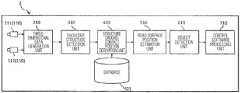
- FIG. 1is a schematic view for describing a first embodiment of the present invention
- FIG. 1( a ) and FIG. 1( b )illustrate a scene viewed from a host vehicle and a block diagram of an object detection device, respectively.
- FIG. 2is a schematic flowchart for executing detection of a shoulder structure of FIG. 1 .
- FIG. 3is a schematic flowchart for estimating a road surface height of FIG. 1 .
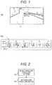
- FIG. 4is a schematic view for describing a processing process of the object detection device of FIG. 1
- FIG. 4( a ) and FIG. 4( b )illustrate a scene viewed from the host vehicle and a V-disparity image each generated by a three-dimensional data generation unit, respectively.
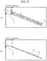
- FIG. 5is a schematic view for describing the processing process of the object detection device of FIG. 1
- FIG. 5( a ) and FIG. 5( b )illustrate a V-disparity image used in a structure ground-contact position derivation unit and a V-disparity image in the middle of being processed in a road surface position estimation unit, respectively.
- FIG. 6is a schematic view for describing the processing process of the object detection device of FIG. 1
- FIG. 6( a ) and FIG. 6( b )illustrate a V-disparity image used in the road surface position estimation unit and an object in image data detected using an object detection unit, respectively.
- FIG. 7is a schematic block diagram for describing a second embodiment of the present invention.
- An object detection device of the present inventionis an object detection device, which detects objects upon a road surface, including: a stereo camera for capturing images of the road surface and a road shoulder and generating image data; a three-dimensional data generation unit for using the image data generated by the stereo camera to calculate disparity data for pixels in the image data; a shoulder structure detection unit for using the disparity data and/or the image data to detect predetermined structures installed on the road shoulder; a structure ground-contact position derivation unit for using disparity data of the structure detected by the shoulder structure detection unit to derive a ground-contact position of the structure; a road surface position estimation unit for estimating the height of the road surface from a ground-contact position of the structure; and an object detection unit for detecting the object upon the road surface by using the disparity data generated by the three-dimensional data generation unit and the height of the road surface estimated by the road surface position estimation unit to separate disparity data corresponding to the road surface and disparity data other than the disparity data from the disparity data generated by the three-dimensional data generation unit.
- a “shoulder structure” in the present specificationmeans a predetermined structure installed in the road shoulder.
- the predetermined structureinclude a shoulder structure 102 (a guardrail), a shoulder structure 103 (a traffic sign), a shoulder structure 104 (a traffic light), and the like illustrated in FIG. 1 to be described later.
- FIG. 1is a schematic view for describing a first embodiment of the present invention.
- the object detection device 1is constituted schematically by a stereo camera 110 , a three-dimensional data generation unit 210 , a shoulder structure detection unit 310 , a structure ground-contact position derivation unit 410 , a road surface position estimation unit 510 , an object detection unit 610 , and a control software processing unit 710 .
- the stereo camera 110captures images of a road surface 101 a and a road shoulder 101 b around a host vehicle and generates image data, and has a pair of camera sensors 111 and 112 capturing the images of the road surface 101 a and the road shoulder 101 b.
- the three-dimensional data generation unit 210uses the image data generated by the stereo camera 110 to calculate disparity data (three-dimensional distance image data) for each pixel in the image data.
- This disparity datacan be obtained by applying a known stereo matching technique using the image data captured by the camera sensors 111 and 112 .
- the above-described stereo matching techniquedetermines a unit region so as to minimize a difference between image signals for each predetermined unit region in two images which have been captured using the camera sensors 111 and 112 and are compared with each other. That is, a region where the same object is projected is detected, thereby forming a three-dimensional distance image.
- the three-dimensional distance imageis referred to as a “disparity image”, and particularly, an image of which a vertical direction is represented by a position V in the vertical direction and a horizontal direction is represented by a disparity value at the position V is referred to as a “V-disparity image”.
- the shoulder structure detection unit 310uses the disparity data calculated by the three-dimensional data generation unit 210 and/or the image data obtained by the camera sensors 111 and 112 to search for a predetermined pattern corresponding to a shoulder structure from the image data, thereby detecting the shoulder structure installed on the road shoulder 101 b.
- the structure ground-contact position derivation unit 410derives a ground-contact position of the shoulder structure detected by the shoulder structure detection unit 310 .
- a derivation method of the ground-contact positionis not particularly limited, and the structure ground-contact position derivation unit preferably uses disparity data of the shoulder structure and/or image data of the shoulder structure to drive the ground-contact position of the shoulder structure.
- a known techniquecan be used as the derivation method. As a result, it is possible to reliably derive the ground-contact position of the shoulder structure.
- ground-contact positions of the shoulder structuremay be calculated at predetermined intervals along the line-of-sight direction.
- the structure ground-contact position derivation unit 410may use the derived ground-contact position of the shoulder structure and the image data generated by the stereo camera 110 to calculate the height of the top of the shoulder structure from the ground (the height of the shoulder structure).
- the object detection device 1can cause the ground-contact position of the shoulder structure not to be used to estimate the road surface height as an abnormal value and can further improve the estimation accuracy of the height of the road surface 101 a.
- the road surface position estimation unit 510estimates the height of the road surface 101 a using the ground-contact position of the shoulder structure derived by the structure ground-contact position derivation unit 410 .
- a method for estimating the height of the road surface 101 ais not particularly limited, and for example, a known technique can be used.
- the height of the road surface 101 ais represented as the height with respect to a plane defined in advance (such as a predetermined horizontal plane).
- the above-described road surface position estimation unit 510preferably uses the ground-contact position of the shoulder structure to estimate the height of the road surface 101 a for each position (segment) in the line-of-sight direction of the stereo camera 110 .
- the object detection device 1can more accurately estimate the height of each portion of the road surface 101 a such as an undulating state in the line-of-sight direction.
- the object detection unit 610uses the disparity data generated by the three-dimensional data generation unit 210 and the height of the road surface 101 a estimated by the road surface position estimation unit 510 to separate disparity data corresponding to the road surface 101 a and disparity data other than the disparity data from the above disparity data, thereby detecting an object on the road surface 101 a (for example, a car 105 traveling in front of the host vehicle as illustrated in a scene A 1 of FIG. 1( a ) ).
- a method for detecting the object on the road surface 101 ais not particularly limited, and for example, a known technique (for example, a technique described in JP 2009-146217 A or the like) can be used.
- the object detection unit 610may detect an object on the road surface 101 a by using the image data obtained by at least one of the camera sensors 111 and 112 in the stereo camera 110 in addition to the disparity data and the height of the road surface 101 a described above from the viewpoint of improving the detection accuracy of the object.
- the control software processing unit 710controls the host vehicle so as to cope with an object detected by the above-described object detection unit 610 and movement of the object.
- the control software processing unit 710incorporates control software capable of controlling the host vehicle in accordance with the movement of the object, and movement of the host vehicle is controlled based on a command from the control software.
- control softwarefor example, known automatic driving assistance software or the like can be adopted.
- FIG. 2is a schematic flowchart for executing detection of the shoulder structure of FIG. 1 .
- the shoulder structure detection unit 310acquires one piece of image data out of the image data obtained by the stereo camera 110 and detects the shoulder structure 102 (the guardrail), the shoulder structure 103 (the traffic sign), the shoulder structure 104 (the traffic light), and the like illustrated in FIG. 1 from a specific pattern included in the image (Step S 21 ).
- the shoulder structure detection unit 310specifies a region where the shoulder structure detected in Step S 21 is located. Incidentally, the specified region is used in the structure ground-contact position derivation unit 410 and the road surface position estimation unit 510 . (Step S 22 )
- FIG. 3is a schematic flowchart for estimating the road surface height of FIG. 1 .
- the road surface position estimation unit 510first sets a region serving as a road surface candidate in the V-disparity image (Step S 31 ).
- a setting method thereofis not particularly limited, but preferably includes at least any of a method of using a road surface position estimated in advance, a method of using a point at infinity of a camera as a reference for region setting, a method of using a partitioned range in a disparity image as valid road data by setting a trapezoidal shape for partitioning a road range, and a method of using detection of a lane marking to determine a road shape.
- the road surface position estimation unit 510extracts disparity data included in a region which is valid and serves as a road surface candidate (Step S 32 ).
- disparity data of a road surface and disparity data of an object such as a car which is likely to exist on the road surfaceare separated.
- a separation method thereofis not particularly limited, but preferably includes at least any method between a method of using a position of the shoulder structure to calculate a position of the shoulder structure closest to a road surface and a method of comparing a disparity value in the vertical direction in disparity data with a predetermined threshold to confirm that the disparity value in the vertical direction gradually decreases toward the point at infinity.
- the road surface position estimation unit 510projects the disparity data of the region serving as the road surface candidate onto a V-disparity space (a coordinate space specified by the vertical axis indicating the position V in the vertical direction and the horizontal axis indicating a disparity value at the position V) to generate a histogram that represents a frequency for the disparity value of each road surface candidate, and as a result, V-disparity road surface representative data is extracted for each disparity value in the vertical direction (Step S 33 ).
- V-disparity spacea coordinate space specified by the vertical axis indicating the position V in the vertical direction and the horizontal axis indicating a disparity value at the position V
- the road surface position estimation unit 510integrates information on the ground-contact position of the shoulder structure detected by the structure ground-contact position derivation unit 410 and the V-disparity road surface representative data to form data for road surface estimation (Step S 34 ).
- a virtual ground-contact positionis calculated using this defined height, and the calculated ground-contact position can be used as the data for road surface estimation (see FIGS. 5( a ) and 5( b ) ).
- the road surface position estimation unit 510uses the data integrated in Step S 34 to calculate a single line (road surface line) passing the vicinity of a pixel having a high histogram frequency (Step S 35 ).
- this single road surface linemay be either a straight line or a curve, or may be a line obtained by combining one or more of these straight lines and curves.
- the road surface position estimation unit 510estimates the height of the road surface using the road surface line calculated in Step 35 (Step S 36 ).
- the object detection device 1is mounted on the host vehicle, and the object detection device 1 is used to detect the object 105 on the road surface 101 a in front of the host vehicle (hereinafter also referred to as the “car 105 ”).
- the shoulder structure 102the guardrail
- the shoulder structure 104the traffic light
- the stereo camera 110 mounted on the vehicleis used to capture images of the surroundings in the progressing direction of the host vehicle including the road surface 101 a and the road shoulder 101 b , thereby generating image data.
- the three-dimensional data generation unit 210uses the image data generated by the stereo camera 110 to calculate a disparity for each pixel in this image data.
- the shoulder structure detection unit 310detects a shoulder structure using the disparity data calculated according to Step S 21 and specifies a region of the shoulder structure according to Step S 22 .
- FIG. 4( b )illustrates a V-disparity image generated by the three-dimensional data generation unit 210 .
- This V-disparity imageillustrates disparity data (a data region R 1 ) of the road surface 101 a which has not been detected yet, disparity data (a data region R 5 ) of the car 105 which has not been detected yet, and the shoulder structure 102 (a data region R 2 ) and the shoulder structure 104 (a data region R 4 ) which have been detected by the shoulder structure detection unit 310 .
- a line represented by reference sign L 1 in FIG. 4( b )indicates a position of a road surface which has not been detected yet but is described as a reference.
- a disparity of the road surface 101 a represented by the data region R 1is lower than other disparities of the shoulder structures 102 and 104 and the like in a scene A 2 illustrated in FIG. 4( a ) . It is considered that a reason thereof is that it becomes difficult to calculate the disparity by stereo matching due to a uniform structure of the road surface 101 a or the visibility of the road surface becomes low due to bad weather.
- the structure ground-contact position derivation unit 410acquires data of the V-disparity image, and uses this data to derive ground-contact positions of the shoulder structures 102 and 104 .
- the ground-contact positions of the shoulder structureare derived at predetermined intervals along the line-of-sight direction.
- ground-contact positions D 2 and D 4 of the shoulder structures 102 and 104 illustrated in FIG. 5( b )are derived from the regions R 2 and R 4 in the V-disparity image corresponding to the shoulder structures 102 and 104 .
- the road surface position estimation unit 510extracts V-disparity road surface representative data D 1 represented by the data region R 1 according to Steps S 31 to S 33 , and then, integrate the V-disparity road surface representative data D 1 and the ground-contact positions D 2 and D 4 of the shoulder structures according to Steps S 34 and S 35 to calculate a road surface line L 2 illustrated in FIG. 5( b ) .
- a calculation method of the above-described road surface line L 2for example, a calculation method of performing linear approximation or the like by an approximation method, such as a least squares approximation method, can be adopted.
- V-disparity road surface representative data D 1is indicated by a circle
- the ground-contact positions D 2 and D 4are indicated by a trapezoid mark and a triangle mark, respectively, in FIG. 5( b ) .
- the road surface position estimation unit 510estimates a road surface height using the road surface line L 2 calculated as above according to Step S 36 .
- the estimated road surface heightis used to specify disparity data of a segment at the same height position such as the road surface 101 a.
- the object detection unit 610separates disparity data indicating the road surface 101 a and the remaining disparity data indicating one other than the road surface 101 a , and uses this separated disparity data to detect a region R 105 corresponding to the car 105 on the road surface 101 a and specify a position of the region R 105 as illustrated in FIG. 6( b ) .
- the object detection unit 610may detect the region R 105 of the car 105 using the information on the ground-contact positions D 2 and D 4 of the shoulder structures 102 and 104 detected by the shoulder structure detection unit 310 together with the disparity data described above. As a result, the processing time required to detect the car 105 is reduced, and it is possible to more reliably prevent confusion between the disparity data corresponding to the car 105 and the disparity data corresponding to the shoulder structures 102 and 104 .
- control software processing unit 710controls the host vehicle so as to cope with the car 105 detected by the object detection unit 610 (for example, to avoid approaching to the car 105 , to travel following the car 105 , to overtake the car 105 , or the like).
- the object detection device 1includes the stereo camera 110 , the three-dimensional data generation unit 210 , the shoulder structure detection unit 310 , the structure ground-contact position derivation unit 410 , the road surface position estimation unit 510 , and the object detection unit 610 described above, and thus, can accurately estimate the height of the road surface 101 a using the ground-contact positions of the shoulder structures 102 and 104 and reliably detect the object 105 present on the road surface 101 a.
- FIG. 7is a schematic block diagram for describing a second embodiment of the present invention.
- an object detection device 2is constituted schematically by the stereo camera 110 , the three-dimensional data generation unit 210 , the shoulder structure detection unit 310 , a structure ground-contact position derivation unit 420 , a database 421 , the road surface position estimation unit 510 , the object detection unit 610 , and the control software processing unit 710 .
- the second embodimentis different from the first embodiment in terms that the structure ground-contact position derivation unit 420 and the shoulder structure database 421 are provided.
- configurations other than the structure ground-contact position derivation unit 420 and the database 421are the same as those of the first embodiment, and thus, the same parts will be denoted by the same reference signs, and detailed descriptions thereof will be omitted.
- the structure ground-contact position derivation unit 420derives a ground-contact position of a shoulder structure using disparity data of the shoulder structure and height information of the shoulder structure stored in the database 421 , which will be described later, in order to estimate the ground-contact position of the detected shoulder structure. Specifically, the structure ground-contact position derivation unit 420 detects a position of the shoulder structure, and derives the ground-contact position of the shoulder structure is derived by subtracting the height from the top position using a height of the shoulder structure stored in the database 421 which will be described later.
- the database 421stores the height information of the shoulder structure.
- the information stored in the database 421is not particularly limited, and may include information such as a position and a range of a shoulder structure in addition to the height information of the shoulder structure, for example.
- the object detection device 2includes the structure ground-contact position derivation unit 420 and the database 421 described above, and thus, can more accurately and reliably derive the ground-contact position of the shoulder structure.
- the object detection device 2can indirectly derive the ground-contact position of the shoulder structure even if it is difficult to derive the ground-contact point of the shoulder structure directly for some reason.
- the object detection device 1that estimates the height of the road surface 101 a using the V-disparity road surface representative data D 1 of the road surface 101 a and the ground-contact positions D 2 and D 4 of the shoulder structures 102 and 104 has been described in the above-described embodiment, but an object detection device that estimates the height of a road surface only from a ground-contact position of a shoulder structure without using V-disparity road surface representative data is also included within the intended scope of the present invention.
- the object detection device 1 including the control software processing unit 710has been described in the above-described embodiments, but it is sufficient for the object detection device of the present invention to be capable of reliably detecting the object present on the road surface, and may be an object detection device that does not include a processing unit such as the control software processing unit 710 .
Landscapes
- Engineering & Computer Science (AREA)
- Physics & Mathematics (AREA)
- General Physics & Mathematics (AREA)
- Theoretical Computer Science (AREA)
- Computer Vision & Pattern Recognition (AREA)
- Multimedia (AREA)
- Radar, Positioning & Navigation (AREA)
- Remote Sensing (AREA)
- Electromagnetism (AREA)
- Signal Processing (AREA)
- Geometry (AREA)
- Traffic Control Systems (AREA)
- Image Processing (AREA)
- Image Analysis (AREA)
- Measurement Of Optical Distance (AREA)
Abstract
Description
- 1,2 object detection device
- 101aroad surface
- 101broad shoulder
- 102,103,104 structure (shoulder structure)
- 105 object
- 110 stereo camera
- 210 three-dimensional data generation unit
- 310 shoulder structure detection unit
- 410,420 structure ground-contact position derivation unit
- 421 database
- 510 road surface position estimation unit
- 610 object detection unit
Claims (4)
Applications Claiming Priority (4)
| Application Number | Priority Date | Filing Date | Title |
|---|---|---|---|
| JP2016-245529 | 2016-12-19 | ||
| JP2016245529AJP6794243B2 (en) | 2016-12-19 | 2016-12-19 | Object detector |
| JPJP2016-245529 | 2016-12-19 | ||
| PCT/JP2017/043937WO2018116841A1 (en) | 2016-12-19 | 2017-12-07 | Object detection device |
Publications (2)
| Publication Number | Publication Date |
|---|---|
| US20190266745A1 US20190266745A1 (en) | 2019-08-29 |
| US11024051B2true US11024051B2 (en) | 2021-06-01 |
Family
ID=62626336
Family Applications (1)
| Application Number | Title | Priority Date | Filing Date |
|---|---|---|---|
| US16/346,029Active2038-03-19US11024051B2 (en) | 2016-12-19 | 2017-12-07 | Object detection device |
Country Status (5)
| Country | Link |
|---|---|
| US (1) | US11024051B2 (en) |
| EP (1) | EP3557527B1 (en) |
| JP (1) | JP6794243B2 (en) |
| CN (1) | CN110088802B (en) |
| WO (1) | WO2018116841A1 (en) |
Cited By (5)
| Publication number | Priority date | Publication date | Assignee | Title |
|---|---|---|---|---|
| US20210309227A1 (en)* | 2020-04-06 | 2021-10-07 | Hyundai Motor Company | Apparatus for controlling autonomous driving of a vehicle, system having the same and method thereof |
| US11511576B2 (en)* | 2020-01-24 | 2022-11-29 | Ford Global Technologies, Llc | Remote trailer maneuver assist system |
| US11541910B1 (en)* | 2022-01-07 | 2023-01-03 | Plusai, Inc. | Methods and apparatus for navigation of an autonomous vehicle based on a location of the autonomous vehicle relative to shouldered objects |
| US20230303079A1 (en)* | 2022-03-25 | 2023-09-28 | Honda Motor Co., Ltd. | Control device |
| US20230303119A1 (en)* | 2022-03-25 | 2023-09-28 | Embark Trucks Inc. | Lane change determination for vehicle on shoulder |
Families Citing this family (8)
| Publication number | Priority date | Publication date | Assignee | Title |
|---|---|---|---|---|
| JP6859907B2 (en)* | 2017-09-08 | 2021-04-14 | トヨタ自動車株式会社 | Vehicle control unit |
| JP6985089B2 (en)* | 2017-09-29 | 2021-12-22 | トヨタ自動車株式会社 | Three-dimensional object grounding judgment device |
| EP3614299A1 (en) | 2018-08-21 | 2020-02-26 | Siemens Aktiengesellschaft | Method and assembly for identifying objects on installations |
| JP7229129B2 (en)* | 2019-09-05 | 2023-02-27 | 京セラ株式会社 | OBJECT DETECTION DEVICE, OBJECT DETECTION SYSTEM, MOBILE OBJECT AND OBJECT DETECTION METHOD |
| US11840238B2 (en)* | 2021-02-05 | 2023-12-12 | Nvidia Corporation | Multi-view geometry-based hazard detection for autonomous systems and applications |
| JP2023079012A (en)* | 2021-11-26 | 2023-06-07 | 日立Astemo株式会社 | External recognition device |
| US20230351769A1 (en)* | 2022-04-29 | 2023-11-02 | Nvidia Corporation | Detecting hazards based on disparity maps using machine learning for autonomous machine systems and applications |
| US20230351638A1 (en)* | 2022-04-29 | 2023-11-02 | Nvidia Corporation | Detecting hazards based on disparity maps using computer vision for autonomous machine systems and applications |
Citations (50)
| Publication number | Priority date | Publication date | Assignee | Title |
|---|---|---|---|---|
| US5874904A (en)* | 1996-08-14 | 1999-02-23 | Fuji Electric Co., Ltd. | Inter-vehicle distance measurement apparatus |
| JPH11213138A (en) | 1998-01-30 | 1999-08-06 | Fuji Heavy Ind Ltd | Outside monitoring device |
| US20040096082A1 (en)* | 2002-08-28 | 2004-05-20 | Hiroaki Nakai | Obstacle detection device and method therefor |
| US20060206243A1 (en)* | 2002-05-03 | 2006-09-14 | Donnelly Corporation, A Corporation Of The State Michigan | Object detection system for vehicle |
| US20070127777A1 (en)* | 2005-12-06 | 2007-06-07 | Nissan Motor Co., Ltd. | Apparatus and method for detecting a road boundary |
| US20080199069A1 (en)* | 2004-12-23 | 2008-08-21 | Jens Schick | Stereo Camera for a Motor Vehicle |
| WO2008107944A1 (en)* | 2007-03-01 | 2008-09-12 | Pioneer Corporation | Lane deviation prevention device, lane deviation prevention method, lane deviation prevention program, and recording medium |
| US7437243B2 (en)* | 2005-03-22 | 2008-10-14 | Nissan Motor Co., Ltd. | Detecting device and method to detect an object based on a road boundary |
| US20080273750A1 (en)* | 2004-11-30 | 2008-11-06 | Nissan Motor Co., Ltd. | Apparatus and Method For Automatically Detecting Objects |
| EP2040196A1 (en) | 2007-09-21 | 2009-03-25 | Honda Motor Co., Ltd. | Road shape estimating device |
| US20090167844A1 (en)* | 2004-08-11 | 2009-07-02 | Tokyo Institute Of Technology | Mobile peripheral monitor |
| US20090214081A1 (en)* | 2008-02-25 | 2009-08-27 | Kabushiki Kaisha Toshiba | Apparatus and method for detecting object |
| US20100235035A1 (en)* | 2006-03-22 | 2010-09-16 | Nissan Motor Co., Ltd. | Avoidance maneuver calculation device, avoidance control device, vehicle having each device, avoidance maneuver calculating method, and avoidance controlling method |
| JP2011022995A (en) | 2009-06-16 | 2011-02-03 | Nippon Soken Inc | Vanishing point estimation device and program |
| US20110261168A1 (en)* | 2008-11-28 | 2011-10-27 | Hitachi Automotive Systems, Ltd. | Camera Device |
| US20110311130A1 (en)* | 2010-03-19 | 2011-12-22 | Oki Semiconductor Co., Ltd. | Image processing apparatus, method, program, and recording medium |
| US20120010808A1 (en)* | 2007-09-27 | 2012-01-12 | Hitachi, Ltd. | Driving Support System |
| US20120185167A1 (en)* | 2009-07-29 | 2012-07-19 | Hitachi Automotive Systems Ltd | Road Shape Recognition Device |
| US20120288154A1 (en)* | 2009-12-28 | 2012-11-15 | Hitachi Automotive Systems, Ltd. | Road-Shoulder Detecting Device and Vehicle Using Road-Shoulder Detecting Device |
| US20130128001A1 (en)* | 2011-11-18 | 2013-05-23 | Ganmei YOU | Method and system for detecting object on a road |
| US20130163821A1 (en)* | 2011-12-22 | 2013-06-27 | Ganmei YOU | Method and device for detecting road region as well as method and device for detecting road line |
| JP2013140515A (en) | 2012-01-05 | 2013-07-18 | Toyota Central R&D Labs Inc | Solid object detection device and program |
| EP2662804A2 (en)* | 2012-05-11 | 2013-11-13 | Ricoh Company, Ltd. | Method and apparatus for detecting continuous road partition |
| US20140086451A1 (en)* | 2012-09-24 | 2014-03-27 | Ricoh Company, Ltd. | Method and apparatus for detecting continuous road partition |
| US20140267630A1 (en)* | 2013-03-15 | 2014-09-18 | Ricoh Company, Limited | Intersection recognizing apparatus and computer-readable storage medium |
| US8867792B2 (en)* | 2011-05-19 | 2014-10-21 | Fuji Jukogyo Kabushiki Kaisha | Environment recognition device and environment recognition method |
| US20150049913A1 (en)* | 2012-05-31 | 2015-02-19 | Ricoh Company, Ltd. | Road surface slope-identifying device, method of identifying road surface slope, and computer program for causing computer to execute road surface slope identification |
| WO2015053100A1 (en)* | 2013-10-07 | 2015-04-16 | 日立オートモティブシステムズ株式会社 | Object detection device and vehicle using same |
| US20150165972A1 (en)* | 2012-06-19 | 2015-06-18 | Toyota Jidosha Kabushiki Kaisha | Roadside object detection apparatus |
| US20150210312A1 (en)* | 2014-01-30 | 2015-07-30 | Mobileye Vision Technologies Ltd. | Systems and methods for detecting low-height objects in a roadway |
| US20150227800A1 (en)* | 2014-02-07 | 2015-08-13 | Toyota Jidosha Kabushiki Kaisha | Marking line detection system and marking line detection method |
| US9122936B2 (en)* | 2012-11-13 | 2015-09-01 | Kabushiki Kaisha Toshiba | Detecting device, detection method, and computer program product |
| JP2015179302A (en) | 2014-03-18 | 2015-10-08 | 株式会社リコー | Solid object detection device, solid object detection method, solid object detection program, and mobile apparatus control system |
| WO2015163028A1 (en) | 2014-04-25 | 2015-10-29 | 日立建機株式会社 | Road surface estimation device and road surface estimation system for mine work-vehicle |
| US20150332103A1 (en)* | 2014-05-19 | 2015-11-19 | Soichiro Yokota | Processing apparatus, computer program product, and processing method |
| US20150332114A1 (en)* | 2014-05-14 | 2015-11-19 | Mobileye Vision Technologies Ltd. | Systems and methods for curb detection and pedestrian hazard assessment |
| US20150356358A1 (en)* | 2013-02-21 | 2015-12-10 | Sharp Kabushiki Kaisha | Obstacle detection device and obstacle detection method |
| US20150371095A1 (en)* | 2013-02-19 | 2015-12-24 | Conti Temic Microelectronic Gmbh | Method and Apparatus for Determining a Road Condition |
| US20160014406A1 (en)* | 2014-07-14 | 2016-01-14 | Sadao Takahashi | Object detection apparatus, object detection method, object detection program, and device control system mountable to moveable apparatus |
| US20160019429A1 (en)* | 2014-07-17 | 2016-01-21 | Tomoko Ishigaki | Image processing apparatus, solid object detection method, solid object detection program, and moving object control system |
| US9242601B2 (en)* | 2012-09-24 | 2016-01-26 | Ricoh Company, Ltd. | Method and device for detecting drivable region of road |
| US20170098132A1 (en)* | 2014-05-19 | 2017-04-06 | Soichiro Yokota | Processing apparatus, processing system, processing program, and processing method |
| US20170220877A1 (en)* | 2014-08-26 | 2017-08-03 | Hitachi Automotive Systems, Ltd. | Object detecting device |
| US20170262734A1 (en)* | 2016-03-08 | 2017-09-14 | Otoichi NAKATA | Image processing apparatus, imaging device, moving object device control system, and image processing method |
| US20180365846A1 (en)* | 2016-03-18 | 2018-12-20 | Shinichi SUMIYOSHI | Image processing apparatus, moving body device control system, computer-readable medium, and image processing method |
| US20190005338A1 (en)* | 2016-02-23 | 2019-01-03 | Genki WATANABE | Image processing apparatus, imaging apparatus, mobile device control system, and recording medium |
| US20190014302A1 (en)* | 2016-02-22 | 2019-01-10 | Genki WATANABE | Image processing apparatus, imaging apparatus, mobile device control system, image processing method, and recording medium |
| US10580155B2 (en)* | 2015-10-29 | 2020-03-03 | Ricoh Company, Ltd. | Image processing apparatus, imaging device, device control system, frequency distribution image generation method, and recording medium |
| US10755116B2 (en)* | 2015-11-27 | 2020-08-25 | Ricoh Company, Ltd. | Image processing apparatus, imaging apparatus, and device control system |
| US10762656B2 (en)* | 2016-11-30 | 2020-09-01 | Ricoh Company, Ltd. | Information processing device, imaging device, apparatus control system, information processing method, and computer program product |
Family Cites Families (5)
| Publication number | Priority date | Publication date | Assignee | Title |
|---|---|---|---|---|
| JP5172314B2 (en) | 2007-12-14 | 2013-03-27 | 日立オートモティブシステムズ株式会社 | Stereo camera device |
| JP2010148058A (en)* | 2008-12-22 | 2010-07-01 | Denso It Laboratory Inc | Device and method for driving support |
| JP5783243B2 (en)* | 2011-02-21 | 2015-09-24 | 日産自動車株式会社 | Periodic stationary object detection apparatus and periodic stationary object detection method |
| JP2012225806A (en)* | 2011-04-20 | 2012-11-15 | Toyota Central R&D Labs Inc | Road gradient estimation device and program |
| CN105270208A (en)* | 2014-07-14 | 2016-01-27 | 刁心玺 | Method and device for tour inspection on road |
- 2016
- 2016-12-19JPJP2016245529Apatent/JP6794243B2/enactiveActive
- 2017
- 2017-12-07EPEP17883461.0Apatent/EP3557527B1/enactiveActive
- 2017-12-07CNCN201780067420.3Apatent/CN110088802B/enactiveActive
- 2017-12-07WOPCT/JP2017/043937patent/WO2018116841A1/ennot_activeCeased
- 2017-12-07USUS16/346,029patent/US11024051B2/enactiveActive
Patent Citations (56)
| Publication number | Priority date | Publication date | Assignee | Title |
|---|---|---|---|---|
| US5874904A (en)* | 1996-08-14 | 1999-02-23 | Fuji Electric Co., Ltd. | Inter-vehicle distance measurement apparatus |
| JPH11213138A (en) | 1998-01-30 | 1999-08-06 | Fuji Heavy Ind Ltd | Outside monitoring device |
| US20030099377A1 (en) | 1998-01-30 | 2003-05-29 | Fuji Jukogyo Kabushiki Kaisha | Vehicle surroundings monitoring apparatus |
| US20060206243A1 (en)* | 2002-05-03 | 2006-09-14 | Donnelly Corporation, A Corporation Of The State Michigan | Object detection system for vehicle |
| US20040096082A1 (en)* | 2002-08-28 | 2004-05-20 | Hiroaki Nakai | Obstacle detection device and method therefor |
| US20090167844A1 (en)* | 2004-08-11 | 2009-07-02 | Tokyo Institute Of Technology | Mobile peripheral monitor |
| US20080273750A1 (en)* | 2004-11-30 | 2008-11-06 | Nissan Motor Co., Ltd. | Apparatus and Method For Automatically Detecting Objects |
| US20080199069A1 (en)* | 2004-12-23 | 2008-08-21 | Jens Schick | Stereo Camera for a Motor Vehicle |
| US7437243B2 (en)* | 2005-03-22 | 2008-10-14 | Nissan Motor Co., Ltd. | Detecting device and method to detect an object based on a road boundary |
| US20070127777A1 (en)* | 2005-12-06 | 2007-06-07 | Nissan Motor Co., Ltd. | Apparatus and method for detecting a road boundary |
| US20100235035A1 (en)* | 2006-03-22 | 2010-09-16 | Nissan Motor Co., Ltd. | Avoidance maneuver calculation device, avoidance control device, vehicle having each device, avoidance maneuver calculating method, and avoidance controlling method |
| WO2008107944A1 (en)* | 2007-03-01 | 2008-09-12 | Pioneer Corporation | Lane deviation prevention device, lane deviation prevention method, lane deviation prevention program, and recording medium |
| EP2040196A1 (en) | 2007-09-21 | 2009-03-25 | Honda Motor Co., Ltd. | Road shape estimating device |
| US20090085913A1 (en) | 2007-09-21 | 2009-04-02 | Honda Motor Co., Ltd. | Road shape estimating device |
| JP2009075938A (en) | 2007-09-21 | 2009-04-09 | Honda Motor Co Ltd | Road shape estimation device |
| US20120010808A1 (en)* | 2007-09-27 | 2012-01-12 | Hitachi, Ltd. | Driving Support System |
| US20090214081A1 (en)* | 2008-02-25 | 2009-08-27 | Kabushiki Kaisha Toshiba | Apparatus and method for detecting object |
| US20110261168A1 (en)* | 2008-11-28 | 2011-10-27 | Hitachi Automotive Systems, Ltd. | Camera Device |
| JP2011022995A (en) | 2009-06-16 | 2011-02-03 | Nippon Soken Inc | Vanishing point estimation device and program |
| US20120185167A1 (en)* | 2009-07-29 | 2012-07-19 | Hitachi Automotive Systems Ltd | Road Shape Recognition Device |
| US20120288154A1 (en)* | 2009-12-28 | 2012-11-15 | Hitachi Automotive Systems, Ltd. | Road-Shoulder Detecting Device and Vehicle Using Road-Shoulder Detecting Device |
| US8873803B2 (en)* | 2009-12-28 | 2014-10-28 | Hitachi Automotive Systems, Ltd. | Road-shoulder detecting device and vehicle using road-shoulder detecting device |
| US20110311130A1 (en)* | 2010-03-19 | 2011-12-22 | Oki Semiconductor Co., Ltd. | Image processing apparatus, method, program, and recording medium |
| US8867792B2 (en)* | 2011-05-19 | 2014-10-21 | Fuji Jukogyo Kabushiki Kaisha | Environment recognition device and environment recognition method |
| US20130128001A1 (en)* | 2011-11-18 | 2013-05-23 | Ganmei YOU | Method and system for detecting object on a road |
| US20130163821A1 (en)* | 2011-12-22 | 2013-06-27 | Ganmei YOU | Method and device for detecting road region as well as method and device for detecting road line |
| JP2013140515A (en) | 2012-01-05 | 2013-07-18 | Toyota Central R&D Labs Inc | Solid object detection device and program |
| JP2013239168A (en)* | 2012-05-11 | 2013-11-28 | Ricoh Co Ltd | Method and apparatus for detecting continuous road partition |
| EP2662804A2 (en)* | 2012-05-11 | 2013-11-13 | Ricoh Company, Ltd. | Method and apparatus for detecting continuous road partition |
| US20150049913A1 (en)* | 2012-05-31 | 2015-02-19 | Ricoh Company, Ltd. | Road surface slope-identifying device, method of identifying road surface slope, and computer program for causing computer to execute road surface slope identification |
| US20150165972A1 (en)* | 2012-06-19 | 2015-06-18 | Toyota Jidosha Kabushiki Kaisha | Roadside object detection apparatus |
| US20140086451A1 (en)* | 2012-09-24 | 2014-03-27 | Ricoh Company, Ltd. | Method and apparatus for detecting continuous road partition |
| US9242601B2 (en)* | 2012-09-24 | 2016-01-26 | Ricoh Company, Ltd. | Method and device for detecting drivable region of road |
| US9122936B2 (en)* | 2012-11-13 | 2015-09-01 | Kabushiki Kaisha Toshiba | Detecting device, detection method, and computer program product |
| US20150371095A1 (en)* | 2013-02-19 | 2015-12-24 | Conti Temic Microelectronic Gmbh | Method and Apparatus for Determining a Road Condition |
| US20150356358A1 (en)* | 2013-02-21 | 2015-12-10 | Sharp Kabushiki Kaisha | Obstacle detection device and obstacle detection method |
| US20140267630A1 (en)* | 2013-03-15 | 2014-09-18 | Ricoh Company, Limited | Intersection recognizing apparatus and computer-readable storage medium |
| US20160253575A1 (en)* | 2013-10-07 | 2016-09-01 | Hitachi Automotive Systems, Ltd. | Object Detection Device and Vehicle Using Same |
| WO2015053100A1 (en)* | 2013-10-07 | 2015-04-16 | 日立オートモティブシステムズ株式会社 | Object detection device and vehicle using same |
| US20150210312A1 (en)* | 2014-01-30 | 2015-07-30 | Mobileye Vision Technologies Ltd. | Systems and methods for detecting low-height objects in a roadway |
| US20150227800A1 (en)* | 2014-02-07 | 2015-08-13 | Toyota Jidosha Kabushiki Kaisha | Marking line detection system and marking line detection method |
| JP2015179302A (en) | 2014-03-18 | 2015-10-08 | 株式会社リコー | Solid object detection device, solid object detection method, solid object detection program, and mobile apparatus control system |
| WO2015163028A1 (en) | 2014-04-25 | 2015-10-29 | 日立建機株式会社 | Road surface estimation device and road surface estimation system for mine work-vehicle |
| US20150332114A1 (en)* | 2014-05-14 | 2015-11-19 | Mobileye Vision Technologies Ltd. | Systems and methods for curb detection and pedestrian hazard assessment |
| US20150332103A1 (en)* | 2014-05-19 | 2015-11-19 | Soichiro Yokota | Processing apparatus, computer program product, and processing method |
| US20170098132A1 (en)* | 2014-05-19 | 2017-04-06 | Soichiro Yokota | Processing apparatus, processing system, processing program, and processing method |
| US20160014406A1 (en)* | 2014-07-14 | 2016-01-14 | Sadao Takahashi | Object detection apparatus, object detection method, object detection program, and device control system mountable to moveable apparatus |
| US20160019429A1 (en)* | 2014-07-17 | 2016-01-21 | Tomoko Ishigaki | Image processing apparatus, solid object detection method, solid object detection program, and moving object control system |
| US20170220877A1 (en)* | 2014-08-26 | 2017-08-03 | Hitachi Automotive Systems, Ltd. | Object detecting device |
| US10580155B2 (en)* | 2015-10-29 | 2020-03-03 | Ricoh Company, Ltd. | Image processing apparatus, imaging device, device control system, frequency distribution image generation method, and recording medium |
| US10755116B2 (en)* | 2015-11-27 | 2020-08-25 | Ricoh Company, Ltd. | Image processing apparatus, imaging apparatus, and device control system |
| US20190014302A1 (en)* | 2016-02-22 | 2019-01-10 | Genki WATANABE | Image processing apparatus, imaging apparatus, mobile device control system, image processing method, and recording medium |
| US20190005338A1 (en)* | 2016-02-23 | 2019-01-03 | Genki WATANABE | Image processing apparatus, imaging apparatus, mobile device control system, and recording medium |
| US20170262734A1 (en)* | 2016-03-08 | 2017-09-14 | Otoichi NAKATA | Image processing apparatus, imaging device, moving object device control system, and image processing method |
| US20180365846A1 (en)* | 2016-03-18 | 2018-12-20 | Shinichi SUMIYOSHI | Image processing apparatus, moving body device control system, computer-readable medium, and image processing method |
| US10762656B2 (en)* | 2016-11-30 | 2020-09-01 | Ricoh Company, Ltd. | Information processing device, imaging device, apparatus control system, information processing method, and computer program product |
Non-Patent Citations (9)
| Title |
|---|
| Extended European Search Report issued in corresponding European Patent Application No. 17883461.0 dated Jul. 17, 2020. |
| International Search Report with English translation and Written Opinion issued in corresponding application No. PCT/JP2017/043937 dated Apr. 10, 2018. |
| Office Action issued in corresponding Japanese Patent Application No. 2016-245529 dated Aug. 25, 2020, with English translation. |
| R. Labayrade et al., "Real Time Obstacle Detection in Stereovision on Non Flat Road Geometry Through ‘V-Disparity’ Representation", Intelligent Vehicle Symposium, 2002, IEEE Jun. 17-21, 2002, vol. 2, Jun. 21, 2002, pp. 646-651. |
| Real Time Obstacle Detection in Stereovision on Non Flat Road Geometry Through V-disparity Representation, Raphael Labayrade et al., IEEE, Jun. 21, 2002, pp. 646-651 (Year: 2002).* |
| Road Segmentation Supervised by an Extended V-Disparity Algorithm for Autonomous Navigation, Nicolas Soquet et al., IEEE,1-4244-1068-1, 2007, pp. 160-165 (Year: 2007).* |
| S. Nedevschi et al., "Stereovision Approach for Obstacle Detection on Non-Planar Roads", Proceedings of the First International Conference on Informatics in Control, Automation and Robotics, Aug. 25, 2004, pp. 11-18. |
| Stereovision approach Non-Planar roads, Sergiu Nedevschi et al., ICINCO, 10.5220/0001139300110018, 2004, pp. 11-18 (Year: 2004).* |
| U-V-Disparity: An efficient algorithm for Stereovision Based Scene Analysis, Zhencheng Hu et al., IEEE,0-7803-8961 -1, 2005, pp. 48-54 (Year: 2005).* |
Cited By (11)
| Publication number | Priority date | Publication date | Assignee | Title |
|---|---|---|---|---|
| US11511576B2 (en)* | 2020-01-24 | 2022-11-29 | Ford Global Technologies, Llc | Remote trailer maneuver assist system |
| US20210309227A1 (en)* | 2020-04-06 | 2021-10-07 | Hyundai Motor Company | Apparatus for controlling autonomous driving of a vehicle, system having the same and method thereof |
| US11685377B2 (en)* | 2020-04-06 | 2023-06-27 | Hyundai Motor Company | Apparatus for controlling autonomous driving of a vehicle, system having the same and method thereof |
| US11541910B1 (en)* | 2022-01-07 | 2023-01-03 | Plusai, Inc. | Methods and apparatus for navigation of an autonomous vehicle based on a location of the autonomous vehicle relative to shouldered objects |
| US11623664B1 (en)* | 2022-01-07 | 2023-04-11 | Plusai, Inc. | Methods and apparatus for navigation of an autonomous vehicle based on a location of the autonomous vehicle relative to shouldered objects |
| US20230303079A1 (en)* | 2022-03-25 | 2023-09-28 | Honda Motor Co., Ltd. | Control device |
| US20230303119A1 (en)* | 2022-03-25 | 2023-09-28 | Embark Trucks Inc. | Lane change determination for vehicle on shoulder |
| US11840257B2 (en)* | 2022-03-25 | 2023-12-12 | Embark Trucks Inc. | Lane change determination for vehicle on shoulder |
| US20240067218A1 (en)* | 2022-03-25 | 2024-02-29 | Embark Trucks Inc. | Lane change determination for vehicle on shoulder |
| US12304490B2 (en)* | 2022-03-25 | 2025-05-20 | Honda Motor Co., Ltd. | Control device |
| US12351212B2 (en)* | 2022-03-25 | 2025-07-08 | Embark Trucks Inc. | Lane change determination for vehicle on shoulder |
Also Published As
| Publication number | Publication date |
|---|---|
| WO2018116841A1 (en) | 2018-06-28 |
| US20190266745A1 (en) | 2019-08-29 |
| JP2018101200A (en) | 2018-06-28 |
| EP3557527A1 (en) | 2019-10-23 |
| CN110088802A (en) | 2019-08-02 |
| CN110088802B (en) | 2023-08-01 |
| JP6794243B2 (en) | 2020-12-02 |
| EP3557527B1 (en) | 2024-06-19 |
| EP3557527A4 (en) | 2020-08-19 |
Similar Documents
| Publication | Publication Date | Title |
|---|---|---|
| US11024051B2 (en) | Object detection device | |
| US11087148B2 (en) | Barrier and guardrail detection using a single camera | |
| JP6416293B2 (en) | Method of tracking a target vehicle approaching a car by a car camera system, a camera system, and a car | |
| US10627228B2 (en) | Object detection device | |
| JP5276637B2 (en) | Lane estimation device | |
| US20150073705A1 (en) | Vehicle environment recognition apparatus | |
| WO2015194371A1 (en) | Object recognition apparatus and vehicle travel controller using same | |
| JP2021510227A (en) | Multispectral system for providing pre-collision alerts | |
| US9697421B2 (en) | Stereoscopic camera apparatus | |
| EP3282389A1 (en) | Image processing apparatus, image capturing apparatus, moving body apparatus control system, image processing method, and program | |
| US11346670B2 (en) | Position estimating device | |
| KR101268282B1 (en) | Lane departure warning system in navigation for vehicle and method thereof | |
| US20230245323A1 (en) | Object tracking device, object tracking method, and storage medium | |
| JP2016173711A (en) | Travel compartment line recognition apparatus | |
| JP5974718B2 (en) | Vehicle travel support device and vehicle travel support method | |
| KR102372390B1 (en) | Lane recognition apparatus and method thereof | |
| JP6763198B2 (en) | Image processing equipment, imaging equipment, mobile device control systems, image processing methods, and programs | |
| JP5983238B2 (en) | Lane boundary detection device and lane boundary detection method | |
| KR101461316B1 (en) | System and method for controling Automatic Guided Vehicles based on color maker using dual camera | |
| JP2017102634A (en) | Image processing apparatus and image processing system | |
| EP3750776B1 (en) | Method and system for detecting a railroad signal | |
| JP2014067320A (en) | Stereo camera device | |
| JP7602336B2 (en) | Outside environment recognition device | |
| KR20180040313A (en) | Road free space detection apparatus and method using a monocular camera |
Legal Events
| Date | Code | Title | Description |
|---|---|---|---|
| AS | Assignment | Owner name:HITACHI AUTOMOTIVE SYSTEMS, LTD., JAPAN Free format text:ASSIGNMENT OF ASSIGNORS INTEREST;ASSIGNORS:GOMEZCABALLERO, FELIPE;TAKEMURA, MASAYUKI;NONAKA, SHINICHI;SIGNING DATES FROM 20190318 TO 20190322;REEL/FRAME:049025/0190 | |
| FEPP | Fee payment procedure | Free format text:ENTITY STATUS SET TO UNDISCOUNTED (ORIGINAL EVENT CODE: BIG.); ENTITY STATUS OF PATENT OWNER: LARGE ENTITY | |
| STPP | Information on status: patent application and granting procedure in general | Free format text:DOCKETED NEW CASE - READY FOR EXAMINATION | |
| STPP | Information on status: patent application and granting procedure in general | Free format text:RESPONSE TO NON-FINAL OFFICE ACTION ENTERED AND FORWARDED TO EXAMINER | |
| STPP | Information on status: patent application and granting procedure in general | Free format text:NOTICE OF ALLOWANCE MAILED -- APPLICATION RECEIVED IN OFFICE OF PUBLICATIONS | |
| STPP | Information on status: patent application and granting procedure in general | Free format text:PUBLICATIONS -- ISSUE FEE PAYMENT RECEIVED | |
| STPP | Information on status: patent application and granting procedure in general | Free format text:PUBLICATIONS -- ISSUE FEE PAYMENT VERIFIED | |
| STCF | Information on status: patent grant | Free format text:PATENTED CASE | |
| AS | Assignment | Owner name:HITACHI ASTEMO, LTD., JAPAN Free format text:CHANGE OF NAME;ASSIGNOR:HITACHI AUTOMOTIVE SYSTEMS, LTD.;REEL/FRAME:057655/0824 Effective date:20210101 | |
| MAFP | Maintenance fee payment | Free format text:PAYMENT OF MAINTENANCE FEE, 4TH YEAR, LARGE ENTITY (ORIGINAL EVENT CODE: M1551); ENTITY STATUS OF PATENT OWNER: LARGE ENTITY Year of fee payment:4 |