US11023047B2 - Electrostatic slide clutch with bidirectional drive circuit - Google Patents
Electrostatic slide clutch with bidirectional drive circuitDownload PDFInfo
- Publication number
- US11023047B2 US11023047B2US15/968,677US201815968677AUS11023047B2US 11023047 B2US11023047 B2US 11023047B2US 201815968677 AUS201815968677 AUS 201815968677AUS 11023047 B2US11023047 B2US 11023047B2
- Authority
- US
- United States
- Prior art keywords
- sheet
- sheet electrode
- electrodes
- electrode
- dielectric layer
- Prior art date
- Legal status (The legal status is an assumption and is not a legal conclusion. Google has not performed a legal analysis and makes no representation as to the accuracy of the status listed.)
- Active
Links
Images


Classifications
- G—PHYSICS
- G06—COMPUTING OR CALCULATING; COUNTING
- G06F—ELECTRIC DIGITAL DATA PROCESSING
- G06F3/00—Input arrangements for transferring data to be processed into a form capable of being handled by the computer; Output arrangements for transferring data from processing unit to output unit, e.g. interface arrangements
- G06F3/01—Input arrangements or combined input and output arrangements for interaction between user and computer
- G06F3/016—Input arrangements with force or tactile feedback as computer generated output to the user
- G—PHYSICS
- G06—COMPUTING OR CALCULATING; COUNTING
- G06F—ELECTRIC DIGITAL DATA PROCESSING
- G06F3/00—Input arrangements for transferring data to be processed into a form capable of being handled by the computer; Output arrangements for transferring data from processing unit to output unit, e.g. interface arrangements
- G06F3/01—Input arrangements or combined input and output arrangements for interaction between user and computer
- G06F3/011—Arrangements for interaction with the human body, e.g. for user immersion in virtual reality
- G06F3/014—Hand-worn input/output arrangements, e.g. data gloves
Definitions
- a state-of-the-art virtual reality (VR) or mixed reality (MR) holographic systemmay immerse a user in a convincing alternative reality, where visual and auditory aspects of virtual objects are represented in a true-to-life manner.
- VR and MR systemsmay fail to provide an equally satisfying tactile experience—i.e., an experience in which virtual objects feel like the real objects they represent.
- True-to-life tactile simulationis also valuable in numerous other application areas besides VR and MR.
- One electrostatic slide clutchcomprises first and second sheet electrodes, a dielectric layer between the first and second electrodes, and a drive circuit.
- the drive circuitis coupled electrically to the first sheet electrode and to the second sheet electrode and configured to move a variable amount of charge bidirectionally between the first and second sheet electrodes, to influence a normal force between the first and second sheet electrodes.
- FIG. 1shows aspects of an example VR system including a body-movement restriction device.
- FIG. 2shows aspects of an example body-movement restriction portion of a haptic device.
- FIG. 3show aspects of an example electrostatic slide clutch of a body-movement restriction portion of a haptic device.
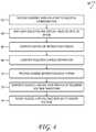
- FIG. 4illustrates an example electrostatic clutch drive process
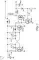
- FIG. 5is a schematic diagram of an example boost circuit for an electrostatic slide clutch.
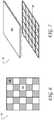
- FIG. 6shows aspects of an example dielectric layer of an electrostatic slide clutch.
- FIGS. 7 and 8show aspects of other example dielectric layers.
- the electrostatic slide clutchincludes a drive circuit being configured to move charge bidirectionally, which may provide realistic resistive force control for various computing device applications, including but not limited to mixed reality and virtual reality applications.
- a body-movement restriction devicemay be incorporated into an electronically functional wearable textile device (e.g., a glove) that includes sensors to sense motions of a user's finger joints.
- an electronically functional wearable textile devicethen may be used to interact with virtual objects displayed on a computer monitor or other suitable display.
- a usermay use hand and/or finger motions to control the shaping of a spinning virtual pottery object displayed on a computer monitor via joint movement sensors incorporated in a glove for controlling a displayed virtual hand.
- body movement restriction devicesmay be used to provide to the user wearing the glove the sensation that hand motion is restricted by touching the displayed spinning virtual pottery object.
- FIG. 1shows aspects of an example virtual-reality (VR) system 10 , configured to present a lifelike VR environment to user 12 .
- the VR system as illustrated in FIG. 1is used to support virtual game play but may be used in numerous other application areas as well.
- VR system 10includes a headset 14 and a plurality of electronically functional wearable devices 16 .
- the headsetincludes a stereoscopic display 18 configured to display virtual imagery in the field of view of the user.
- the stereoscopic displayis see-through, enabling real-world and virtual imagery to be admixed in the user's field of view. That approach is referred to as augmented or mixed reality (MR).
- MRaugmented or mixed reality
- signal encoding the virtual display imageryis sent to the stereoscopic display via on-board computer 20 .
- the on-board computerincludes at least one processor 22 and associated computer memory 24 .
- on-board computer 20may be coupled communicatively to one or more off-board computers on a network.
- the virtual display imagery that user 12 seesmay, in some examples, be composed and/or rendered by an off-board computer. In other examples, the virtual display imagery may be composed and rendered on-board.
- Headset 14includes stereophonic loudspeakers 26 that enable user 12 to experience immersive VR audio.
- Electronically functional wearable devices 16 of VR system 10are configured to further augment the immersive VR experience by providing lifelike physical sensation responsive to user interaction with the virtual environment.
- electronically functional wearable device 16 Atakes the form of a glove, which is worn on the hand of the user
- electronically functional wearable device 16 Btakes the form of a sleeve worn around the arm.
- a sleeve supporting a haptic devicemay be worn alternatively or additionally on the leg or other body part in some examples.
- Each electronically functional wearable device 16may be configured to provide a resistive physical sensation in response to detection of contact between the body of user 12 and a virtual display object projected into a field of view of the user.
- the resistive physical sensationmay be provided whenever the hand of the user intersects virtual display object 28 , for example.
- electronically functional wearable glove device 16 Aoptionally includes a skin-pressure simulation portion 30 .
- the skin-pressure simulation portionis a component of the haptic device configured to apply touch-simulating pressure to the user's skin in the vicinity of contact with a virtual display object.
- the skin-pressure simulation portionmay include an actuator configured to apply pressure in a direction normal to the surface of the skin.
- the skin-pressure simulation portionmay include a piezoelectric or voice-coil type actuator, for example.
- electronically functional wearable device 16 Amay include one or more body-configuration sensors (not shown in FIG. 1 ) and may be coupled operatively to one or more computers of VR system 10 , such as on-board computer 20 of headset 14 .
- the computermay host a model of the virtual environment and may also track the position of the user's hand with reference to the real-world coordinates of that model.
- the actuatorWhen contact between the hand and a solid virtual object is indicated, the actuator may be energized such that pressure is applied to the skin. The actuator may be de-energized when contact is no longer indicated.
- each haptic device 16includes at least one body-movement restriction portion 32 .
- a body-movement restriction portion 32may be used either with or without an associated skin-pressure simulation portion 30 , in various implementations.
- a haptic devicemay include a different number of body-movement restriction portions (e.g., one for each of the thumb, forefinger and ring finger).
- FIG. 2shows aspects of an example body-movement restriction portion 32 of n electronically functional glove device 16 A.
- electronically functional glove device 16 Ais worn on hand 33 of a user.
- the illustrated body-movement restriction portionincludes an electrostatic slide clutch 34 .
- the electrostatic slide clutchis configured to vary the sliding and/or static frictional force between two substrates 36 movable translationally with respect to each other.
- first substrate 36 Ais coupled directly to the user's hand on a first side of a skeletomuscular joint 38 .
- Second substrate 36 Bis coupled indirectly to the opposite side of the skeletomuscular joint, via connector 40 .
- the connectormay take the form of a wire or yarn segment, for example.
- the electrostatic slide clutch and connectorare arranged between inner layer 41 A and outer layer 41 B of a flexible, fabric glove.
- Connector 40connects second substrate 36 B to various locations on the inner layer of the fabric glove.
- a single clutch and connectorcontrol motion restriction for all of the skeletomuscular joints of the finger.
- two or more electrostatic slide clutchesmay be provided for a given finger. More particularly, two or more electrostatic slide clutches may be configured to provide independent resistive force at two or more joints of the finger, via independent connectors.
- Electrostatic slide clutch 34optionally includes a tensioner 44 . In the illustrated example, the tensioner is coupled between first substrate 36 A and second substrate 36 B and configured to apply tension to guide wire 40 .
- the tensionermay include a spring or elastic band, for example.
- the result of the tension in the guide wireis to provide an unbalanced force that draws grip portion 42 towards the clutch when the clutch is unlocked.
- the frictional force exerted by the clutchbalances the force of the tensioner, so that the grip portion ceases to be drawn towards the clutch.
- both the first and second substrates 36may be coupled directly to the user's body at a location extending over skeletomuscular joint 38 .
- both the first and second substratesmay be coupled indirectly to the user's body, via appropriate connectors and grip portions.
- the body-movement restriction portionmay take the form of a tube around the finger that becomes stiffer to restrict movement.
- the substratesmay be arranged as overlapping scales akin to a medieval armor glove.
- FIG. 3shows a schematic view of electrostatic slide clutch 34 in one example.
- the electrostatic slide clutchincludes multiple parallel layers of each of a first sheet electrode 46 A and a second sheet electrode 46 B oriented parallel to the first sheet electrode. In other examples, a single layer of each electrode may be used.
- the first sheet electrodeis formed on or bonded to first substrate 36 A
- the second sheet electrodeis formed on or bonded to second substrate 36 B.
- each of the first and second substratesmay be secured directly to the body of the user, secured indirectly via a grip portion and/or guide wire, or otherwise closely coupled to an articulable region of the user's body.
- an itself electrodemay be applied directly to the skin, such that no distinct substrate is required for that electrode.
- first sheet electrode 46 A and second sheet electrode 46 Bmay include an electrically conductive, continuous or discontinuous (e.g., patterned) film applied to an underlying substrate.
- a filmmay be applied using solution-process methods, for instance.
- electrically conductive filmsinclude ink-jet, screen-printed, gravure printed, or flexographic-printed films.
- Other examplesinclude slot-die coatings and spin coatings of conductive films.
- Graphite, silver, or gold films, for example,may also be used.
- a metal-film electrodemay be formed by vacuum deposition methods such as physical vapor deposition (PVD) of one or more metals—aluminum or copper, etc.—onto a substrate.
- PVDphysical vapor deposition
- Chemical vapor deposition, electroless plating, electroplating, atomic-layer deposition, and/or other forms of material depositionmay also be used.
- Suitable electrode substratesmay be rigid or flexible, depending on the detailed configuration of electrostatic slide clutch 34 .
- first and second sheet electrodes 46may be flexible.
- a flexible electrodemay be formed from a woven or non-woven conductive fabric, for instance.
- one or both of the first and second sheet electrodesmay have relatively high sheet resistance, as very little current is drawn through the sheet electrodes during operation of electrostatic slide clutch 34 (vide infra).
- a dielectric layer 48is disposed on first sheet electrode 46 A on a face of the first sheet electrode opposing second sheet electrode 46 B.
- the dielectric layeris arranged in slidable contact with the second sheet electrode.
- electrostatic slide clutch 34further comprises a second dielectric layer disposed on the second sheet electrode on a face of the second sheet electrode opposing the first sheet electrode.
- the first and second dielectric layersmay be arranged in slidable contact with each other.
- each of first sheet electrode 46 A, second sheet electrode 46 B, and dielectric layer 48present multiple parallel layers.
- This configurationmay result from folding the first and second sheet electrodes and the dielectric into zig-zag (i.e., accordion) shape.
- multiple discrete sheet-electrodemay be used, with connections between equivalent electrodes made externally. Both tactics serve to increase the interfacial electrode area while limiting the form factor of the electrostatic slide clutch.
- electrostatic slide clutch 34may include a guide 50 configured to guide the relative sliding motion of the first and second sheet electrodes.
- the guidemay include a slot for one or both of the first and second sheet electrodes.
- the guideis fixedly coupled to first substrate 36 A.
- the guidemay accommodate a plurality of pairs of opposing first and second sheet electrodes, to achieve increased frictional force.
- guide 50accommodates a displacement sensor 52 , which provides an output signal responsive to the displacement of the second sheet electrode or substrate relative to the first sheet electrode or substrate.
- a displacement sensor 52which provides an output signal responsive to the displacement of the second sheet electrode or substrate relative to the first sheet electrode or substrate.
- the second sheet electrode or substratemay include a plurality of contrast features detectable by a small photodiode mounted to the first sheet electrode or substrate, so as to generate a digital pulsetrain as the second sheet electrode slides along the first. The relative position of the two electrodes may be revealed, accordingly, by a digital counter clocked by the pulsetrain.
- Analog resistive and capacitive displacement sensorsmay also be used.
- a displacement signalmay be derived from a sensor not located on guide 50 , but elsewhere in body-movement restriction portion 32 .
- output signal from the displacement sensormay facilitate various computations described herein—e.g., estimating the degree of extension of the user's finger and the area of overlap between the first and second sheet electrodes (vide infra).
- Electrostatic slide clutch 34further includes a drive circuit 54 electrically coupled to first sheet electrode 46 A and to second sheet electrode 46 B and configured to charge and discharge the first and second sheet electrodes by a controlled, variable amount.
- the effect of the variable charge and dischargeis to influence the normal force between the first and second sheet electrodes.
- Positive voltagemay be applied to the first sheet electrode relative to the second sheet electrode, or vice versa.
- an alternating voltage of suitable frequencymay be used, to facilitate dynamically changing the force applied during sliding operation, as described below.
- haptic device 16may be configured to provide the sensation of physical contact with one or more of the virtual objects.
- drive circuit 54includes a pulse-width modulator 56 and a high-voltage booster 58 .
- the drive circuitis coupled operatively to computer 20 and configured to execute an electrostatic clutch-drive process to provide haptic feedback to user in a VR environment.
- FIG. 4illustrates an example electrostatic clutch-drive process 60 in one example embodiment.
- computer 20maintains a mapping of the virtual objects in the user's environment.
- the mappingmay include the position and shape of each virtual object.
- the mappingmay also include certain material properties (e.g., stress-strain properties) of each virtual object and a matrix of interaction forces among the various virtual objects.
- the computerreceives sensory data relating to the user's skeletal configuration—from displacement sensors 52 , image data from the hand, etc.
- the computermaps the user's skeleton and the virtual objects onto the same 3D space.
- the computercomputes a matrix of interaction forces between the virtual objects and the parts of the user's body that are equipped with a body-movement restriction portion 32 . More particularly, the computer may be configured to resolve each of the interaction forces into suitable vector components, and thereby compute the required friction force to be realized at each electrostatic slide clutch 34 of the associated body-movement restriction portion. In configurations in which there is the electrostatic slide clutch includes an optional tensioner 44 , the restorative force exerted by the tensioner may be included in the calculation.
- the computercomputes the required amount of charge to be separated across sheet electrodes 46 .
- this calculationmay incorporate the overlap area as an input parameter.
- signal responsive to the overlap areamay be obtained from displacement sensors 52 .
- Additional parameters in the calculationmay include the amount and polarity of the charge already separated across the sheet electrodes, which may be estimated and stored in computer 20 as a system variable.
- this datais provided to pulse-width modulator (PWM) 56 .
- PWMpulse-width modulator
- the PWMcomposes a pulse-modulated a.c. signal (possibly with a d.c. offset voltage) corresponding to (i.e., having an integral over time which is proportional to) the d.c. control voltage supplied by the computer. More specifically, the PWM generates a scaled, low-voltage replica of a voltage waveform that, when applied across sheet electrodes 46 , will cause the desired quantity of charge to flow in the desired direction.
- the waveform generated by the PWMmay be governed by any suitable conditions or parameters. For instance, the applied pulses may be rectangular or sinusoidal.
- the applied pulsesmay have a fixed amplitude and variable period, or a variable amplitude and period.
- the pulse amplitudemay switch between or among discrete voltage values—e.g., between ⁇ 5 and +5 volts.
- the PWMmay receive sensory input indicative of the variable area of overlap, and apply the same as an input parameter in determining the appropriate voltage waveform.
- the output of the PWMis fed to high-voltage booster 58 , which scales the voltage up to the required level—e.g., to within a range of ⁇ 1000 to +1000 volts, depending upon the electrode and dielectric materials and structures used.
- FIG. 5provides a schematic diagram of high-voltage booster 58 in one example.
- the material properties of dielectric layer 48may be selected for suitable resistance to sliding wear and to provide a suitably high coefficient of static and/or sliding friction, so that an increase in the normal force between the dielectric layer and second sheet electrode 46 B restricts the relative sliding motion of the first and second sheet electrodes.
- Dielectric layer 48may be of a thickness selected to achieve a suitably strong normal force at a given voltage, and thereby reduce the operating voltage for operation of electrostatic clutch 34 . Both the electric field strength and the charge are inversely proportional to the distance between the electrodes, so the normal force is inversely proportional to the square of the distance and directly proportional to the surface area of overlap between the first and second sheet electrodes. In some implementations, roughening, texturing, and/or shaping the electrodes over an appropriate length scale may amplify the effective overlap area.
- dielectric layer 48includes a dielectric material.
- the dielectric materialmay be selected to exhibit a high dielectric strength in order to support a large electric field without suffering breakdown. Moreover, the dielectric material may exhibit a relatively high dielectric constant to achieve a relatively high normal force at a given voltage. Increasing the dielectric constant of the dielectric material increases proportionately the surface charge on first and second sheet electrodes 46 , resulting in a proportional increase in the normal force at a given voltage.
- a 10 ⁇ m thick electrically insulating poly(vinylidenefluoride-trifluoroethylene-chlorofluoroethylene)) (P(VDF-TrFE-CFE)) sheetprovides adequate normal force with 150 volts applied between the first and second sheet electrodes.
- the dielectric material of dielectric layer 48may be a homogeneous, sheet-forming material, such as a polymer of suitable dielectric constant and dielectric strength.
- the dielectric layermay be a solid material composite (i.e., a mixture) comprising the dielectric material dispersed and immobilized within a polymer matrix.
- the dielectricmay include finely divided aluminum oxide or barium titanate dispersed in poly(vinylidenefluoride) (PVDF). Table 1 lists physical properties of various example dielectric materials.
- Dielectric layer 48may be formed on or bonded to first sheet electrode 46 A in any suitable manner.
- first sheet electrode 46 Amay include a conductive fabric.
- the dielectric material of dielectric layer 48may permeate the conductive fabric of the first sheet electrode.
- the dielectric layermay be blade-cast or spin-cast, for example, to a thickness of 1 ⁇ m, or deposited on the first sheet electrode by vapor-phase deposition. Both physical vapor deposition and chemical vapor deposition are envisaged. Table 1 provides non-limiting examples of dielectric materials amenable to vapor-phase deposition.
- dielectric layer 48may be subject to surface treatment.
- a chemical surface treatmentmay be used to modify coefficients of static and/or sliding friction, or to increase the wear resistance or dielectric strength of the dielectric layer.
- Physical surface treatmentsuch as mechanical abrasion may be used to roughen the dielectric layer to increase the frictional coefficients, or to prepare the sheet for chemical surface treatment, for example.
- Second sheet electrode 46 Bmay also be subject to chemical and physical surface treatment, for similar advantages.
- the dielectric layermay have a heterogeneous surface structure (which also may be referred to as a composite surface structure) having zones differing in one or more of dielectric composition, matrix composition, surface treatment and/or surface relief.
- the length scale of the heterogeneityi.e., the size of the various zones
- the length scaleis not particularly limited; the length scale may differ from one embodiment to the next and may range from microns to tens of millimeters.
- the heterogeneous surface structure of dielectric layer 48 ′includes a millimeter- to micrometer-scale pattern of such zones 76 .
- zones of other dimensionsare also envisaged.
- the illustrated exampleshows a checkerboard pattern of alternating zones 76 A and 76 B, as a non-limiting example of a patterning of zones.
- This approachmay facilitate fine-tuning of the dielectric constant and surface properties, such as the frictional coefficients.
- Strictly or substantially two-dimensional zone patternsmay be used in some examples.
- the zone patternalso may extend normal to the dielectric layer.
- FIG. 7One such example is shown in FIG. 7 .
- the pattern of zones of dielectric layer 48 ′′includes surface features interlocking three-dimensionally with complementary surface features of second sheet electrode 46 B′′. This configuration increases the effective frictional forces between the first and second sheet electrodes.
- zone patternsmay be formed on the dielectric layer 48 ′′ and/or second sheet electrode 46 B′′ via a micromolding or embossing procedure. In other examples, the zone patterns may be formed by lithography and/or etching. In the examples provided above, the heterogeneous surface structure of the dielectric layers is on the micrometer-to-millimeter scale.
- a motion restricting apparatusmay comprise a heterogeneous surface structure in the form of macroscopically separate frictional and dielectric surfaces.
- FIG. 8shows an example of such a structure. Separating frictional surface 76 B from dielectric surface 76 A lessens wear on the dielectric surface with repeated actuation of electrostatic slide clutch 34 .
- This approachalso may facilitate subjecting the frictional and dielectric surfaces to different surface treatments. For example, the dielectric surface may be treated with a lubricant to lessen wear, while the frictional surface may remain unlubricated, in order to preserve the high frictional coefficients.
- second sheet electrode 46 B′′′includes a low-friction zone 78 A opposing the dielectric surface of the dielectric layer and a high-friction zone 78 B opposing the frictional surface of the dielectric layer.
- the first and second sheet electrodesmay be shaped so as to provide a region of overlap of a predetermined or changing geometry as the electrodes move against each other. For instance, non-rectangular electrodes may provide a changing area of overlap (and normal force, therefore) as one electrode slides over the other.
- haptic device 16may be non-wearable, but instead integrated into a control, such as a dial.
- the electrostatic slide clutch of the haptic devicemay provide variable resistance to the turning of the dial, or give the sensation of a series of detents, for example, pursuant to resistive applied via a drive circuit 54 .
- an electrostatic slide clutch as described hereinmay be used to provide controlled resistance between moving parts of a mechanical system of virtually any description.
- an electrostatic slide clutchmay be arranged in a hinge linking the keyboard and display portions of a laptop computer. The clutch may be configured to lock the display portion at various angles relative to the keyboard portion, and to unlock to enable the laptop computer to be closed.
- a body-movement restriction portion in the form of an electrostatic slide clutchmay be used in medical, rather than computer-technology applications. Controllable body-movement restriction may be useful for the patient rehabilitating from a skeletomuscular injury such as back/knee injury, or brain injury such as stroke. In other examples, a body-movement restriction portion may be used as an active restraint for management of seizures or potentially dangerous body movements associated with autism, psychiatric disorders, or acute substance abuse.
- a body-movement restriction portion in the form of an electrostatic slide clutchmay also be amenable to various industrial-safety applications.
- machine vision or other environment-sensing componentrymay be used to assess whether persons are in close proximity to potentially dangerous machinery. Persons wearing an appropriate body-movement restriction portion operatively coupled to the environment-sensing componentry may be protected from drawing too close to the machinery, extending a hand or finger into a cutting device, etc.
- a body-movement restriction portion worn by a workermay be configured for skeletal strain mitigation. When the worker is carrying a heavy object, the body-movement restriction portion may lock into place, providing additional resistance to motion and relieving stress on the worker's fingers, wrists, arms, legs, and other skeletal joints.
- an electrostatic slide clutch as described abovemay be used in a variety of electromechanical applications.
- the clutchmay be used to provide positive braking for a servomechanical (e.g., a robotic, soft robotic, and/or ball-joint) actuator.
- a servomechanicale.g., a robotic, soft robotic, and/or ball-joint
- One aspect of this disclosureis directed to an electrostatic slide clutch comprising: a first sheet electrode; a second sheet electrode oriented parallel to first sheet electrode; a dielectric layer between the first and second sheet electrodes; and a drive circuit coupled electrically to the first sheet electrode and to the second sheet electrode, the drive circuit being configured to move a variable amount of charge bidirectionally between the first and second sheet electrodes, to influence a normal force between the first and second sheet electrodes.
- the drive circuitincludes a pulse-width modulator configured to vary an output pulse width in response to a control signal.
- the output pulse widthis of fixed amplitude.
- the control signalis varied depending upon the charge already separated across the first and second sheet electrodes.
- the electrostatic slide clutchfurther comprises a displacement sensor responsive to an area of overlap between the first and second sheet electrodes, wherein the control signal depends upon an output of the displacement sensor.
- the drive circuitincludes high-voltage booster, and wherein the output of the pulse-width modulator is boosted by the high-voltage booster.
- the dielectric layeris a first dielectric layer
- the electrostatic slide clutchfurther comprising a second dielectric layer disposed on the second sheet electrode on a face of the second sheet electrode opposing the first sheet electrode, and wherein the first and second dielectric layers are arranged in slidable contact with each other.
- the dielectric layerincludes a dielectric material dispersed in a polymer matrix.
- the dielectric materialincludes a composite material including barium titanate.
- the dielectric layerincludes a vapor-phase deposited film.
- a haptic devicecomprising a body-movement restriction portion including an electrostatic slide clutch, comprising: a first sheet electrode; a second sheet electrode opposing the first sheet electrode; a dielectric layer disposed on the first sheet electrode opposing the second sheet electrode; and a drive circuit coupled electrically to the first sheet electrode and to the second sheet electrode, the drive circuit being configured to move a variable amount of charge bidirectionally between the first and second sheet electrodes, to influence a normal force between the first and second sheet electrodes.
- the drive circuitincludes a pulse-width modulator and a high-voltage booster.
- the haptic devicefurther comprises a tensioner configured to apply sliding force to the second sheet electrode relative to the first sheet electrode.
- the dielectric layeris arranged in slidable contact with the second sheet electrode, and wherein an increase in the normal force restricts relative sliding motion of the first and second sheet electrodes.
- the haptic devicefurther comprises a displacement sensor configured to provide an output signal responsive to displacement of the second sheet electrode relative to the first sheet electrode.
- one or both of the first and second sheet electrodesis flexible.
- the first and second sheet electrodes and the dielectric layerare arranged in parallel and folded in a zig-zag manner, to achieve increased frictional force for a given applied voltage.
- the first and second sheet electrodesare among a plurality of pairs of parallel sheet electrodes, and wherein a dielectric layer is arranged between the electrodes of each pair.
- the first sheet electrodeis configured to be positioned on a first side of a skeletomuscular joint of the user, and the second sheet electrode is coupled indirectly to a second, opposite side of the skeletomuscular joint.
- a virtual reality systemcomprising: a body-movement restriction portion in the form of an electrostatic slide clutch, comprising: a first electrode; a second electrode oriented parallel to first sheet electrode, the second sheet electrode disposed on a second substrate; a dielectric layer disposed on the first sheet electrode on a face of the first sheet electrode opposing the second sheet electrode; and a drive circuit coupled electrically to the first sheet electrode and to the second sheet electrode, the drive circuit being configured to move a variable amount of charge bidirectionally between the first and second sheet electrodes, to influence a normal force between the first and second sheet electrodes in response to detection of contact between the body of the user and a virtual display object projected into a field of view of the user.
Landscapes
- Engineering & Computer Science (AREA)
- General Engineering & Computer Science (AREA)
- Theoretical Computer Science (AREA)
- Human Computer Interaction (AREA)
- Physics & Mathematics (AREA)
- General Physics & Mathematics (AREA)
- User Interface Of Digital Computer (AREA)
Abstract
Description
| TABLE 1 |
| Dielectric Materials |
| Dielectric | Dielectric | ||||
| Materiala | VDc | Staticb | Slidingb | Constant | Strengthd |
| PTFE | 0.04 | 2.1 | 500 | ||
| Al2O3/Sapphire | yes | 1.05-1.13 | 1.4 | 9.34 | 16 |
| SiO2 | yes | 3.9 | |||
| Si3N4 | yes | 7.5 | |||
| Dragon Skin | 2.7-3 | 13 | |||
| Medium | |||||
| P7670 | 2.7-3 | 30-80 | |||
| Polyimide | 0.63 | 0.48 | 3.4 | 303 | |
| Polyurethane | 7.1-30 | ||||
| PVC | 3.5-8 | ||||
| PE | 2.5 | ||||
| HTT C1 | yes | 20-25 | |||
| HTT T1 | yes | 60 | 80 | ||
| SU8-2000 | no | 4.1 | |||
| SU8-3000 | no | 3.2 | |||
| Plexiglas | 1.9 | ||||
| Pyrex | no | 0.9-1 | 0.4 | 4.7 | |
| Natural rubber | no | 1-4 | 0.5-1 | 2-2.5 | |
| BaTiO3 | yes | 1200-10000 | |||
| PET | 2.9 | 50-100 | |||
| PFA | 2.1 | ||||
| Parylene | yes | 2.5-2.67 | |||
| ZrO2 | yes | 10-23 | |||
| (Pb,La)(Zr,Ti)O3 | yes | 440 | |||
| (PLZT) | |||||
| Ta2O5 | yes | 25 | |||
| TiO2 | yes | 80-170 | |||
| aDragon Skin Medium is a product of Smooth-On Inc. of Macungie, PA. P7670 is a product of Wacker Chemie AG of München, Germany; Kapton Mylar, Teonex, Tetoron, and HFF are products of Dupont of Wilmington, DE; HTT C1 and HTT T1 are products of Arkema of Colombes, France; SU8-2000 and SU8-3000 are products of Microchem Corp. of Westborough, MA. | |||||
| bCoefficients of static and sliding friction. | |||||
| cYes indicates that the volts per material is amenable to vapor deposition. | |||||
| dDielectric strength in units of micrometer. | |||||
Claims (20)
Priority Applications (3)
| Application Number | Priority Date | Filing Date | Title |
|---|---|---|---|
| US15/968,677US11023047B2 (en) | 2018-05-01 | 2018-05-01 | Electrostatic slide clutch with bidirectional drive circuit |
| EP19727527.4AEP3769187B1 (en) | 2018-05-01 | 2019-04-22 | Electrostatic slide clutch with bidirectional drive circuit |
| PCT/US2019/028425WO2019212775A1 (en) | 2018-05-01 | 2019-04-22 | Electrostatic slide clutch with bidirectional drive circuit |
Applications Claiming Priority (1)
| Application Number | Priority Date | Filing Date | Title |
|---|---|---|---|
| US15/968,677US11023047B2 (en) | 2018-05-01 | 2018-05-01 | Electrostatic slide clutch with bidirectional drive circuit |
Publications (2)
| Publication Number | Publication Date |
|---|---|
| US20190339773A1 US20190339773A1 (en) | 2019-11-07 |
| US11023047B2true US11023047B2 (en) | 2021-06-01 |
Family
ID=66676873
Family Applications (1)
| Application Number | Title | Priority Date | Filing Date |
|---|---|---|---|
| US15/968,677ActiveUS11023047B2 (en) | 2018-05-01 | 2018-05-01 | Electrostatic slide clutch with bidirectional drive circuit |
Country Status (3)
| Country | Link |
|---|---|
| US (1) | US11023047B2 (en) |
| EP (1) | EP3769187B1 (en) |
| WO (1) | WO2019212775A1 (en) |
Cited By (2)
| Publication number | Priority date | Publication date | Assignee | Title |
|---|---|---|---|---|
| US11566952B2 (en)* | 2020-08-06 | 2023-01-31 | Korea Institute Of Science And Technology | Tensile force detecting device with elastic elements |
| US12407276B2 (en) | 2021-04-30 | 2025-09-02 | Estat Actuation, Inc. | Rotary electroadhesive clutch |
Families Citing this family (14)
| Publication number | Priority date | Publication date | Assignee | Title |
|---|---|---|---|---|
| US11036295B2 (en) | 2016-11-23 | 2021-06-15 | Microsoft Technology Licensing, Llc | Electrostatic slide clutch |
| WO2020003177A1 (en) | 2018-06-28 | 2020-01-02 | 3M Innovative Properties Company | Low voltage electrostatic jamming device |
| US11979098B2 (en)* | 2018-06-28 | 2024-05-07 | 3M Innovative Properties Company | Jamming device with jamming sheets |
| US11984823B2 (en)* | 2018-06-28 | 2024-05-14 | 3M Innovative Properties Company | Electrostatic jamming devices and methods of making such devices |
| US10852825B2 (en) | 2018-09-06 | 2020-12-01 | Microsoft Technology Licensing, Llc | Selective restriction of skeletal joint motion |
| US10942572B1 (en)* | 2019-02-12 | 2021-03-09 | Facebook Technologies, Llc | Systems, methods, and articles using polarizable media in haptic-jamming |
| US10860102B2 (en) | 2019-05-08 | 2020-12-08 | Microsoft Technology Licensing, Llc | Guide for supporting flexible articulating structure |
| US11061476B2 (en) | 2019-05-24 | 2021-07-13 | Microsoft Technology Licensing, Llc | Haptic feedback apparatus |
| US11054905B2 (en)* | 2019-05-24 | 2021-07-06 | Microsoft Technology Licensing, Llc | Motion-restricting apparatus with common base electrode |
| KR102702585B1 (en)* | 2019-12-03 | 2024-09-04 | 삼성전자주식회사 | Electronic apparatus and Method for controlling the display apparatus thereof |
| WO2021207330A2 (en)* | 2020-04-08 | 2021-10-14 | Tactual Labs Co. | Non-uniform electrode spacing with a bend sensor |
| TWI861614B (en)* | 2022-12-02 | 2024-11-11 | 宏達國際電子股份有限公司 | Glove |
| US11874964B1 (en)* | 2022-12-02 | 2024-01-16 | Htc Corporation | Glove |
| CN119501974A (en)* | 2024-12-24 | 2025-02-25 | 西安交通大学 | Electrostatic adsorption clutch force feedback data gloves based on teleoperation system and design method thereof |
Citations (170)
| Publication number | Priority date | Publication date | Assignee | Title |
|---|---|---|---|---|
| US2897425A (en) | 1958-10-21 | 1959-07-28 | Robert W Waring | Method of and apparatus for producing electrostatic force |
| US4753442A (en) | 1987-04-20 | 1988-06-28 | Bland Clyde S W | Baseball glove with automatic ball return device |
| US4987332A (en) | 1988-09-30 | 1991-01-22 | Pentel Kabushiki Kaisha | Robot hand for electrostatically applying thin workpiece to mold |
| US5173834A (en) | 1989-06-02 | 1992-12-22 | Roland Dg Corporation | Electrostatic attraction apparatus |
| US5184319A (en) | 1990-02-02 | 1993-02-02 | Kramer James F | Force feedback and textures simulating interface device |
| JPH06126661A (en) | 1992-10-12 | 1994-05-10 | Mitsubishi Cable Ind Ltd | Handling device of micropart |
| US5429140A (en) | 1993-06-04 | 1995-07-04 | Greenleaf Medical Systems, Inc. | Integrated virtual reality rehabilitation system |
| US5516249A (en) | 1994-05-10 | 1996-05-14 | Technical Research Associates, Inc. | Exoskeleton with kinesthetic feedback and robotic control |
| US5631861A (en) | 1990-02-02 | 1997-05-20 | Virtual Technologies, Inc. | Force feedback and texture simulating interface device |
| EP0782843A2 (en) | 1996-01-02 | 1997-07-09 | Benito Ferrati | Orthopedic rehabilitation apparatus using virtual reality units |
| EP0981423A2 (en) | 1997-05-12 | 2000-03-01 | Virtual Technologies, Inc. | Force-feedback interface device for the hand |
| US6128004A (en) | 1996-03-29 | 2000-10-03 | Fakespace, Inc. | Virtual reality glove system with fabric conductors |
| US6413229B1 (en) | 1997-05-12 | 2002-07-02 | Virtual Technologies, Inc | Force-feedback interface device for the hand |
| US20020130673A1 (en) | 2000-04-05 | 2002-09-19 | Sri International | Electroactive polymer sensors |
| US6524681B1 (en) | 1997-04-08 | 2003-02-25 | 3M Innovative Properties Company | Patterned surface friction materials, clutch plate members and methods of making and using same |
| US20030125781A1 (en) | 2001-12-28 | 2003-07-03 | Matsushita Electric Works, Ltd. | Wearable human motion applicator |
| US20040084261A1 (en) | 2002-11-01 | 2004-05-06 | Performance Friction Corporation | Brake rotor with a surface having a plurality of indentations formed therein |
| US20040102723A1 (en) | 2002-11-25 | 2004-05-27 | Horst Robert W. | Active muscle assistance device and method |
| US20040174337A1 (en) | 2002-12-27 | 2004-09-09 | Akira Kubota | Force-feedback supply apparatus and image correcting method |
| US6790308B2 (en) | 2003-01-03 | 2004-09-14 | Borgwarner Inc. | Method and apparatus for making clutch plate with multi segment friction material |
| US20050012485A1 (en) | 2003-07-14 | 2005-01-20 | Dundon Michael J. | Interactive body suit and interactive limb covers |
| JP2005227111A (en) | 2004-02-12 | 2005-08-25 | Masaru Hakoda | Woven-fabric-like electrode, and substance filter unit |
| WO2005089176A2 (en) | 2004-03-12 | 2005-09-29 | Sri International | Mechanical meta-materials |
| US20060094989A1 (en) | 2002-09-04 | 2006-05-04 | Scott Timothy Roderick D | Movement facilitation device |
| US20060152098A1 (en) | 2005-01-10 | 2006-07-13 | Horst Robert W | High-torque motor |
| US20060261516A1 (en)* | 2003-03-26 | 2006-11-23 | Riken | Process for producing dielectric insulating thin film, and dielectric insulating material |
| US20070016265A1 (en) | 2005-02-09 | 2007-01-18 | Alfred E. Mann Institute For Biomedical Engineering At The University Of S. California | Method and system for training adaptive control of limb movement |
| US7166953B2 (en) | 2001-03-02 | 2007-01-23 | Jon Heim | Electroactive polymer rotary clutch motors |
| US20070129846A1 (en) | 2005-08-16 | 2007-06-07 | Brainlab Ag | Anthropomorphic medical robot arm with movement restrictions |
| CN100998527A (en) | 2007-01-08 | 2007-07-18 | 张为众 | Artificial simulation arm |
| US20070195482A1 (en) | 2006-02-23 | 2007-08-23 | Varian Semiconductor Equipment Associates, Inc. | Johnsen-Rahbek electrostatic chuck driven with AC voltage |
| US20080059131A1 (en) | 2006-08-29 | 2008-03-06 | Canon Kabushiki Kaisha | Force sense presentation device, mixed reality system, information processing method, and information processing apparatus |
| US20080089002A1 (en) | 2006-06-05 | 2008-04-17 | Sri International | Electroadhesion |
| US20080153590A1 (en) | 2006-12-07 | 2008-06-26 | Cel-Kom, Llc | Tactile wearable gaming device |
| US20090102620A1 (en) | 2007-10-19 | 2009-04-23 | Sony Corporation | Force/tactile feedback device |
| US7545349B2 (en) | 2005-03-08 | 2009-06-09 | Seiko Epson Corporation | Display device and display module of movable body |
| US20100041521A1 (en) | 2006-09-01 | 2010-02-18 | Bioservo Technologies Ab | Strengthening glove |
| US20100045251A1 (en)* | 2006-11-20 | 2010-02-25 | Fujitsu Ten Limited | Voltage output circuit, integrated circuit and electronic device |
| US20100085169A1 (en) | 2008-10-02 | 2010-04-08 | Ivan Poupyrev | User Interface Feedback Apparatus, User Interface Feedback Method, and Program |
| US20100141407A1 (en) | 2008-12-10 | 2010-06-10 | Immersion Corporation | Method and Apparatus for Providing Haptic Feedback from Haptic Textile |
| US20110071664A1 (en) | 2009-09-22 | 2011-03-24 | Gm Global Technology Operations, Inc. | Human grasp assist device and method of use |
| US20110101823A1 (en) | 2008-02-29 | 2011-05-05 | Auckland Uniservices Limited | Actuator |
| US20110187637A1 (en) | 2010-01-29 | 2011-08-04 | David Scott Nichols | Tactile Input Apparatus |
| US20110193362A1 (en) | 2010-02-10 | 2011-08-11 | Sri International | Electroadhesive gripping |
| WO2011116357A2 (en) | 2010-03-19 | 2011-09-22 | Sri International | Materials for electroadhesion and electrolaminates |
| US20110234414A1 (en) | 2010-03-26 | 2011-09-29 | Luis Ojeda | Wearable live electrical circuit detection device |
| US8049772B2 (en) | 2005-10-27 | 2011-11-01 | Reald Inc. | Temperature compensation for the differential expansion of an autostereoscopic lenticular array and display screen |
| US20120029399A1 (en) | 2009-04-09 | 2012-02-02 | Yoshiyuki Sankai | Wearable type movement assisting apparatus |
| US20120086366A1 (en) | 2009-02-19 | 2012-04-12 | Auckland Uniservices Limited | System and method for dynamic self-sensing of dielectric elastomer actuators |
| US20120109025A1 (en) | 2009-03-20 | 2012-05-03 | Northeastern University | Multiple degree of freedom rehabilitation system having a smart fluid-based, multi-mode actuator |
| US20120154974A1 (en) | 2010-12-16 | 2012-06-21 | Applied Materials, Inc. | High efficiency electrostatic chuck assembly for semiconductor wafer processing |
| US20120182720A1 (en) | 2011-01-18 | 2012-07-19 | Desmond Albert Walsh | Illuminating safety glove |
| GB2488760A (en) | 2011-03-01 | 2012-09-12 | Angus Everett Strover | Prosthetic hand with digits actuated by muscles via strings |
| US20130072829A1 (en) | 2010-03-23 | 2013-03-21 | Davide Fausti | Hand rehabilitation device |
| US20130226350A1 (en) | 2012-02-29 | 2013-08-29 | The U.S.A. As Represented By The Administrator Of The National Aeronautics And Space Administration | Control of a glove-based grasp assist device |
| US20130242455A1 (en) | 2010-02-10 | 2013-09-19 | Sri International | Electroadhesive Handling And Manipulation |
| US20130285577A1 (en) | 2010-10-18 | 2013-10-31 | Auckland Uniservices Limited | Dielectric elastomer self-sensing using plane approximation |
| US20130294875A1 (en) | 2012-05-02 | 2013-11-07 | Sri International | Electroadhesive Conveying Surfaces |
| US20130330162A1 (en) | 2011-12-28 | 2013-12-12 | Panasonic Corporation | Robotic arm |
| US20140035306A1 (en) | 2011-03-21 | 2014-02-06 | Sri International | Mobile robotic manipulator system |
| US20140162598A1 (en) | 2010-11-17 | 2014-06-12 | Antony-Euclid C. Villa-Real | Customer-controlled instant-response anti-fraud/anti-identity theft devices (with true- personal identity verification), method and systems for secured global applications in personal/business e-banking, e-commerce, e-medical/health insurance checker, e-education/research/invention, e-disaster advisor, e-immigration, e-airport/aircraft security, e-military/e-law enforcement, with or without NFC component and system, with cellular/satellite phone/internet/multi-media functions |
| US20140215684A1 (en) | 2013-02-07 | 2014-08-07 | Timothy J. Hardy | Pressure Sensing Glove |
| US20140277739A1 (en) | 2013-03-15 | 2014-09-18 | Sri International | Exosuit System |
| US20140352161A1 (en) | 2013-05-31 | 2014-12-04 | Stanley Black & Decker, Inc. | Laser level system |
| US20150123647A1 (en) | 2012-06-14 | 2015-05-07 | Auckland Uniservices Limited | Self-sensing dielectric elastomer device |
| US20150132974A1 (en) | 2013-11-13 | 2015-05-14 | David W. Kapella | Adapter for using two one-way light bulbs in a three-way light socket |
| US9148074B2 (en) | 2010-04-16 | 2015-09-29 | Deregallera Holdings Ltd. | Apparatus for use as a motor or generator |
| US9180866B2 (en) | 2011-12-14 | 2015-11-10 | Schaeffler Technologies Gmbh & Co. Kg | Clutch device |
| US20150321339A1 (en) | 2012-09-17 | 2015-11-12 | President And Fellows Of Harvard College | Soft exosuit for assistance with human motion |
| US20160004308A1 (en)* | 2014-07-02 | 2016-01-07 | Immersion Corporation | Systems and Methods for Surface Elements that Provide Electrostatic Haptic Effects |
| US20160025459A1 (en) | 2013-02-14 | 2016-01-28 | Teijin Aramid Gmbh | Hard-ballistic article and process to manufacture said article |
| WO2016012480A1 (en) | 2014-07-25 | 2016-01-28 | Commissariat à l'énergie atomique et aux énergies alternatives | Device for assisting the grip of the thumb of the hand |
| US20160030835A1 (en) | 2013-07-12 | 2016-02-04 | Chris Argiro | Video-game console for allied touchscreen media |
| US20160070347A1 (en) | 2014-06-09 | 2016-03-10 | Bebop Sensors, Inc. | Sensor system integrated with a glove |
| WO2016057963A1 (en) | 2014-10-09 | 2016-04-14 | Carnegie Mellon University | Electrostatic clutch |
| US20160115707A1 (en) | 2014-10-27 | 2016-04-28 | PD2F, Inc. | Accessory mount for a hunting blind |
| US20160124548A1 (en) | 2014-11-03 | 2016-05-05 | Northwestern University | Materials and structures for haptic displays with simultaneous sensing and actuation |
| US20160120734A1 (en) | 2014-10-30 | 2016-05-05 | Elwha Llc | Garment system including at least one sensor and at least one actuator responsive to the sensor and related methods |
| WO2016070078A1 (en) | 2014-10-30 | 2016-05-06 | Bebop Sensors, Inc. | Sensor system integrated with a glove |
| US20160162022A1 (en) | 2014-12-08 | 2016-06-09 | Rohit Seth | Wearable wireless hmi device |
| US20160187973A1 (en) | 2014-12-30 | 2016-06-30 | Stmicroelectronics Pte Ltd | Flexible smart glove |
| US20160187977A1 (en) | 2014-12-30 | 2016-06-30 | Immersion Corporation | Deformable haptic wearables with variable physical properties |
| US20160209448A1 (en) | 2015-01-16 | 2016-07-21 | Robert H. Currie | Voltage Detector Safety Glove |
| US20160213548A1 (en) | 2015-01-28 | 2016-07-28 | Panasonic Intellectual Property Management Co., Ltd. | Assist garment, method for controlling controller of assist garment, and recording medium |
| US20160224115A1 (en)* | 2015-01-30 | 2016-08-04 | Immersion Corporation | Electrostatic haptic actuator and user interface with an electrostatic haptic actuator |
| US20160259417A1 (en) | 2014-07-21 | 2016-09-08 | Dexta Robotics | Hand exoskeleton force feedback system |
| US20160278948A1 (en) | 2015-03-27 | 2016-09-29 | Other Lab, Llc | Lower-leg exoskeleton system and method |
| US20160313630A1 (en) | 2015-04-27 | 2016-10-27 | Sage Elmohtaseb | Omnidirectional Bracket for Cameras and Accessories |
| US20160342207A1 (en) | 2015-05-20 | 2016-11-24 | Sony Computer Entertainment Inc. | Electromagnet-laden glove for haptic pressure feedback |
| US20160363887A1 (en) | 2012-03-15 | 2016-12-15 | Kentaro Nodera | Powder container, powder supply device, and image forming apparatus including same |
| US20160363997A1 (en) | 2015-06-14 | 2016-12-15 | Sony Interactive Entertainment Inc. | Gloves that include haptic feedback for use with hmd systems |
| US20160361179A1 (en) | 2014-01-31 | 2016-12-15 | Nuada, Lda | Joint assistive and locking device |
| US20160378071A1 (en) | 2014-09-02 | 2016-12-29 | Apple Inc. | Wearable electronic device |
| US20170014111A1 (en)* | 2015-07-17 | 2017-01-19 | Hoowaki, Llc | Microstructured Surface |
| DE102015113827A1 (en) | 2015-08-20 | 2017-02-23 | Jörg Jurkat | Orthosis for the reciprocal coupling of two body joints |
| US20170055596A1 (en) | 2015-08-28 | 2017-03-02 | Raquel Smith Colby | Smart Clothing for Simulated Touch and Concussive Force |
| US20170061753A1 (en) | 2015-08-25 | 2017-03-02 | Immersion Corporation | Bistable haptic feedback generator |
| FR3040803A1 (en) | 2015-09-08 | 2017-03-10 | Commissariat Energie Atomique | GLOVE FOR VIRTUAL OR REMOTE HANDLING AND ASSOCIATED VIRTUAL OR REMOTE HANDLING SYSTEM |
| US20170131770A1 (en) | 2015-11-06 | 2017-05-11 | Oculus Vr, Llc | Virtual reality garment capable of jamming user movement |
| US20170131769A1 (en) | 2015-11-09 | 2017-05-11 | Oculus Vr, Llc | Virtual reality garment configured to restrict user movement by repositioning a rigid cuff relative to the user |
| CN106726027A (en) | 2016-02-24 | 2017-05-31 | 吉林大学 | A kind of drive lacking prosthetic hand |
| US20170160807A1 (en) | 2015-12-08 | 2017-06-08 | Oculus Vr, Llc | Resisting user movement using actuated tendons |
| US20170168375A1 (en) | 2015-05-22 | 2017-06-15 | Timothy P. Lajoie | Modular video attachment with vibration dampening |
| US20170168565A1 (en) | 2014-03-02 | 2017-06-15 | Drexel University | Wearable Devices, Wearable Robotic Devices, Gloves, and Systems, Methods, and Computer Program Products Interacting with the Same |
| US20170165567A1 (en)* | 2015-12-10 | 2017-06-15 | Palm Laboratories Inc. | Haptic mechanism for virtual reality and augmented reality interfaces |
| US20170176267A1 (en) | 2015-12-17 | 2017-06-22 | Oculus Vr, Llc | Indexable strain sensor |
| US20170185152A1 (en) | 2015-11-20 | 2017-06-29 | Oculus Vr, Llc | Restricting user movement via connecting tendons in a garment to a jamming mechanism |
| US20170212589A1 (en) | 2016-01-27 | 2017-07-27 | Tactai, Inc. | Providing fingertip tactile feedback from virtual objects |
| US20170210302A1 (en) | 2016-01-27 | 2017-07-27 | Phong Le | Automobile smartphone extended arm and Dash Cam |
| US20170222576A1 (en)* | 2014-10-09 | 2017-08-03 | Carnegie Mellon University, A Pennsylvania Non-Profit Corporation | Electrostatic clutch |
| US20170235213A1 (en) | 2014-10-22 | 2017-08-17 | Gopro, Inc. | Quick-Release Ball-and-Socket Joint Camera Mount |
| US20170248272A1 (en) | 2014-10-20 | 2017-08-31 | Robert Bosch Gmbh | Safety Garment |
| US20170273374A1 (en) | 2016-03-24 | 2017-09-28 | Warwick Mills Inc. | Wearable safety warning and measurement system |
| US20170319950A1 (en) | 2016-05-04 | 2017-11-09 | Thomas F Buchanan, IV | Exo Tendon Motion Capture Glove Device with Haptic Grip Response |
| WO2017199035A1 (en) | 2016-05-18 | 2017-11-23 | Aylesbury Automation Limited | Electroadhesive gripper |
| US9851082B2 (en) | 2012-05-18 | 2017-12-26 | Jack Sealey Limited | Lighting device |
| US20170371416A1 (en) | 2014-12-30 | 2017-12-28 | Philip Zeitler | Haptic devices and methods |
| US20180039302A1 (en) | 2016-08-02 | 2018-02-08 | Immersion Corporation | Systems and methods for deformation and haptic effects |
| WO2018031476A1 (en) | 2016-08-09 | 2018-02-15 | Google Llc | Haptic feedback mechanism for an interactive garment |
| US20180056104A1 (en) | 2016-08-23 | 2018-03-01 | Superflex, Inc. | Systems and methods for assistive exosuit system |
| US20180077976A1 (en) | 2016-09-20 | 2018-03-22 | Oculus Vr, Llc | Actuated tendon pairs in a virtual reality device |
| US20180081436A1 (en) | 2016-09-20 | 2018-03-22 | Oculus Vr, Llc | Composite ribbon in a virtual reality device |
| US20180081439A1 (en) | 2015-04-14 | 2018-03-22 | John James Daniels | Wearable Electronic, Multi-Sensory, Human/Machine, Human/Human Interfaces |
| US20180081437A1 (en) | 2016-09-21 | 2018-03-22 | Apple Inc. | Dynamically configurable input structure with tactile overlay |
| US9931235B2 (en) | 2014-12-12 | 2018-04-03 | Harris Corporation | Passive locking hand exoskeleton |
| WO2018059737A1 (en) | 2016-09-29 | 2018-04-05 | Go Touch Vr Sas | Haptic device, for interaction with virtual reality or augmented reality systems |
| US9939468B1 (en) | 2017-05-05 | 2018-04-10 | Michael J. Dyszel | Wearable non contacting AC voltage detection system |
| US20180098583A1 (en) | 2016-10-12 | 2018-04-12 | Oculus Vr, Llc | Force grounding wristband for haptic glove |
| US20180107277A1 (en) | 2016-10-17 | 2018-04-19 | Oculus Vr, Llc | Inflatable actuators in virtual reality |
| US20180140441A1 (en) | 2015-04-30 | 2018-05-24 | Hy5Pro As | Control of Digits for Artificial Hand |
| US20180143687A1 (en) | 2016-11-23 | 2018-05-24 | Microsoft Technology Licensing, Llc | Electrostatic slide clutch |
| US20180151281A1 (en) | 2016-11-28 | 2018-05-31 | Immersion Corporation | Magneto-sensitive elastomers for haptic feedback |
| US20180153722A1 (en) | 2016-08-23 | 2018-06-07 | Superflex, Inc. | Patch systems for use with assistive exosuit |
| FI127459B (en) | 2017-05-05 | 2018-06-29 | Pulseon Oy | A strap for a biometric monitor and a biometric monitor connected to the strap |
| US10012276B2 (en) | 2014-06-24 | 2018-07-03 | Sri International | System and method for electrically controllable transmissions |
| US10013062B1 (en) | 2017-06-09 | 2018-07-03 | Oculus Vr, Llc | Fluid-actuated haptic feedback jamming device for movement restriction in haptic devices |
| EP3343325A1 (en) | 2016-12-27 | 2018-07-04 | Oculus VR, LLC | Large scale integration of haptic devices |
| WO2018122106A1 (en) | 2016-12-29 | 2018-07-05 | Eth Zurich | Soft wearable muscle assisting device |
| US20180196515A1 (en) | 2017-01-11 | 2018-07-12 | International Business Machines Corporation | Simulating obstruction in a virtual environment |
| US20180260052A1 (en) | 2017-03-09 | 2018-09-13 | Google Llc | Connector Integration for Smart Clothing |
| US20180258562A1 (en) | 2017-03-09 | 2018-09-13 | Google Llc | Conductive Yarn Structure for Interactive Textiles |
| US10082875B1 (en) | 2017-06-05 | 2018-09-25 | Korea Institute Of Science And Technology | Vibrating apparatus, system and method for generating tactile stimulation |
| US20180311570A1 (en) | 2016-05-04 | 2018-11-01 | Thomas F. Buchanan | Exo Tendon Motion Capture Glove Device with Haptic Grip Response |
| US20180324896A1 (en) | 2016-10-10 | 2018-11-08 | At&T Intellectual Property I, L.P. | Disengaging movement assistance |
| US20180319020A1 (en) | 2016-01-12 | 2018-11-08 | Grabit, Inc. | Methods and systems for combined negative pressure and electroadhesion-based manipulation in manufacturing |
| US20180335841A1 (en) | 2017-05-19 | 2018-11-22 | Axonvr Corporation | Haptic feedback glove |
| US20180368559A1 (en) | 2017-06-21 | 2018-12-27 | Apple Inc. | Electronic Devices With Input-Output Devices |
| US20180373331A1 (en) | 2017-06-26 | 2018-12-27 | Microsoft Technology Licensing, Llc | Flexible magnetic actuator |
| US20190004602A1 (en) | 2017-06-30 | 2019-01-03 | Microsoft Technology Licensing, Llc | Haptic feedback system |
| US20190102927A1 (en) | 2017-09-29 | 2019-04-04 | Sony Interactive Entertainment Inc. | Rendering of virtual hand pose based on detected hand input |
| US20190101981A1 (en) | 2017-09-29 | 2019-04-04 | Apple Inc. | Imu-based glove |
| US20190176320A1 (en) | 2017-12-07 | 2019-06-13 | Sarcos Corp. | Resistance-Based Joint Constraint for a Master Robotic System |
| US20190204921A1 (en) | 2017-12-29 | 2019-07-04 | Haptx, Inc. | Haptic feedback glove |
| US20190209086A1 (en) | 2018-01-05 | 2019-07-11 | Rehabotics Medical Technology Corp. | Fixed-sensor finger action detecting glove |
| US20190247050A1 (en) | 2006-11-21 | 2019-08-15 | David S. Goldsmith | Integrated system for the infixion and retrieval of implants |
| US20190282131A1 (en) | 2018-03-15 | 2019-09-19 | Seismic Holdings, Inc. | Management of biomechanical achievements |
| US10474236B1 (en) | 2017-09-13 | 2019-11-12 | Facebook Technologies, Llc | Haptic device for variable bending resistance |
| US20190346938A1 (en) | 2018-05-09 | 2019-11-14 | Apple Inc. | Finger-Mounted Device with Fabric |
| US20190352808A1 (en) | 2018-05-17 | 2019-11-21 | Microsoft Technology Licensing, Llc | Electronically functional yarn and textile |
| US20200012345A1 (en) | 2016-09-19 | 2020-01-09 | Apple Inc. | Finger Beam for Generating Haptic Feedback |
| US20200012344A1 (en) | 2018-07-05 | 2020-01-09 | Bebop Sensors, Inc. | One-size-fits-all data glove |
| US20200016363A1 (en) | 2012-06-27 | 2020-01-16 | Vincent John Macri | Digital virtual limb and body interaction |
| US20200029635A1 (en) | 2018-07-26 | 2020-01-30 | Microsoft Technology Licensing, Llc | Motion-restricting wearable safety device |
| US20200081532A1 (en) | 2018-09-06 | 2020-03-12 | Microsoft Technology Licensing, Llc | Selective restriction of skeletal joint motion |
| US20200081533A1 (en) | 2018-09-07 | 2020-03-12 | Microsoft Technology Licensing, Llc | Wearable device having regions of varying stiffnesses |
| US10663016B2 (en) | 2017-10-09 | 2020-05-26 | Microsoft Technology Licensing, Llc | Electrostatic rotary clutch |
| US20200170750A1 (en) | 2018-11-29 | 2020-06-04 | Engineered Medical Solutions Co., LLC | Systems, devices and methods for securing cameras and supplemental lighting in surgical environments |
| US20200371591A1 (en) | 2019-05-24 | 2020-11-26 | Microsoft Technology Licensing, Llc | Motion-restricting apparatus with common base electrode |
| US20200371590A1 (en) | 2019-05-24 | 2020-11-26 | Microsoft Technology Licensing, Llc | Haptic feedback apparatus |
| US10860102B2 (en) | 2019-05-08 | 2020-12-08 | Microsoft Technology Licensing, Llc | Guide for supporting flexible articulating structure |
- 2018
- 2018-05-01USUS15/968,677patent/US11023047B2/enactiveActive
- 2019
- 2019-04-22WOPCT/US2019/028425patent/WO2019212775A1/ennot_activeCeased
- 2019-04-22EPEP19727527.4Apatent/EP3769187B1/enactiveActive
Patent Citations (266)
| Publication number | Priority date | Publication date | Assignee | Title |
|---|---|---|---|---|
| US2897425A (en) | 1958-10-21 | 1959-07-28 | Robert W Waring | Method of and apparatus for producing electrostatic force |
| US4753442A (en) | 1987-04-20 | 1988-06-28 | Bland Clyde S W | Baseball glove with automatic ball return device |
| US4987332A (en) | 1988-09-30 | 1991-01-22 | Pentel Kabushiki Kaisha | Robot hand for electrostatically applying thin workpiece to mold |
| US5173834A (en) | 1989-06-02 | 1992-12-22 | Roland Dg Corporation | Electrostatic attraction apparatus |
| US20060115348A1 (en) | 1990-02-02 | 2006-06-01 | Kramer James F | Force feedback and texture simulating interface device |
| US5184319A (en) | 1990-02-02 | 1993-02-02 | Kramer James F | Force feedback and textures simulating interface device |
| US7390157B2 (en) | 1990-02-02 | 2008-06-24 | Immersion Corporation | Force feedback and texture simulating interface device |
| US5631861A (en) | 1990-02-02 | 1997-05-20 | Virtual Technologies, Inc. | Force feedback and texture simulating interface device |
| JPH06126661A (en) | 1992-10-12 | 1994-05-10 | Mitsubishi Cable Ind Ltd | Handling device of micropart |
| US5429140A (en) | 1993-06-04 | 1995-07-04 | Greenleaf Medical Systems, Inc. | Integrated virtual reality rehabilitation system |
| US5516249A (en) | 1994-05-10 | 1996-05-14 | Technical Research Associates, Inc. | Exoskeleton with kinesthetic feedback and robotic control |
| EP0782843A2 (en) | 1996-01-02 | 1997-07-09 | Benito Ferrati | Orthopedic rehabilitation apparatus using virtual reality units |
| US6128004A (en) | 1996-03-29 | 2000-10-03 | Fakespace, Inc. | Virtual reality glove system with fabric conductors |
| US6524681B1 (en) | 1997-04-08 | 2003-02-25 | 3M Innovative Properties Company | Patterned surface friction materials, clutch plate members and methods of making and using same |
| US6413229B1 (en) | 1997-05-12 | 2002-07-02 | Virtual Technologies, Inc | Force-feedback interface device for the hand |
| EP0981423A2 (en) | 1997-05-12 | 2000-03-01 | Virtual Technologies, Inc. | Force-feedback interface device for the hand |
| US20020130673A1 (en) | 2000-04-05 | 2002-09-19 | Sri International | Electroactive polymer sensors |
| US6809462B2 (en) | 2000-04-05 | 2004-10-26 | Sri International | Electroactive polymer sensors |
| US7166953B2 (en) | 2001-03-02 | 2007-01-23 | Jon Heim | Electroactive polymer rotary clutch motors |
| US20030125781A1 (en) | 2001-12-28 | 2003-07-03 | Matsushita Electric Works, Ltd. | Wearable human motion applicator |
| US7056297B2 (en) | 2001-12-28 | 2006-06-06 | Matsushita Electric Works, Ltd. | Wearable human motion applicator |
| US7481782B2 (en) | 2002-09-04 | 2009-01-27 | Northern Sydney Area Health Service | Movement facilitation device |
| US20060094989A1 (en) | 2002-09-04 | 2006-05-04 | Scott Timothy Roderick D | Movement facilitation device |
| US20040084261A1 (en) | 2002-11-01 | 2004-05-06 | Performance Friction Corporation | Brake rotor with a surface having a plurality of indentations formed therein |
| US6966882B2 (en) | 2002-11-25 | 2005-11-22 | Tibion Corporation | Active muscle assistance device and method |
| US20060004307A1 (en) | 2002-11-25 | 2006-01-05 | Horst Robert W | Active muscle assistance device and method |
| US20100318006A1 (en) | 2002-11-25 | 2010-12-16 | Horst Robert W | Power regeneration in active muscle assistance device and method |
| US7537573B2 (en) | 2002-11-25 | 2009-05-26 | Tibion Corporation | Active muscle assistance and resistance device and method |
| US20040102723A1 (en) | 2002-11-25 | 2004-05-27 | Horst Robert W. | Active muscle assistance device and method |
| US20120053498A1 (en) | 2002-11-25 | 2012-03-01 | Horst Robert W | Intention-based therapy device and method |
| US7250935B2 (en) | 2002-12-27 | 2007-07-31 | Seiko Epson Corporation | Force-feedback supply apparatus and image correcting method |
| US20040174337A1 (en) | 2002-12-27 | 2004-09-09 | Akira Kubota | Force-feedback supply apparatus and image correcting method |
| US6790308B2 (en) | 2003-01-03 | 2004-09-14 | Borgwarner Inc. | Method and apparatus for making clutch plate with multi segment friction material |
| US20060261516A1 (en)* | 2003-03-26 | 2006-11-23 | Riken | Process for producing dielectric insulating thin film, and dielectric insulating material |
| US7407895B2 (en) | 2003-03-26 | 2008-08-05 | Riken | Process for producing dielectric insulating thin film, and dielectric insulating material |
| US20050012485A1 (en) | 2003-07-14 | 2005-01-20 | Dundon Michael J. | Interactive body suit and interactive limb covers |
| US7046151B2 (en) | 2003-07-14 | 2006-05-16 | Michael J. Dundon | Interactive body suit and interactive limb covers |
| JP2005227111A (en) | 2004-02-12 | 2005-08-25 | Masaru Hakoda | Woven-fabric-like electrode, and substance filter unit |
| US8164232B2 (en) | 2004-03-12 | 2012-04-24 | Sri International | Mechanical meta-materials |
| WO2005089176A2 (en) | 2004-03-12 | 2005-09-29 | Sri International | Mechanical meta-materials |
| US20100007240A1 (en)* | 2004-03-12 | 2010-01-14 | Sri International | Mechanical meta-materials |
| US20060152098A1 (en) | 2005-01-10 | 2006-07-13 | Horst Robert W | High-torque motor |
| US20070016265A1 (en) | 2005-02-09 | 2007-01-18 | Alfred E. Mann Institute For Biomedical Engineering At The University Of S. California | Method and system for training adaptive control of limb movement |
| US7545349B2 (en) | 2005-03-08 | 2009-06-09 | Seiko Epson Corporation | Display device and display module of movable body |
| US8160743B2 (en) | 2005-08-16 | 2012-04-17 | Brainlab Ag | Anthropomorphic medical robot arm with movement restrictions |
| US20070129846A1 (en) | 2005-08-16 | 2007-06-07 | Brainlab Ag | Anthropomorphic medical robot arm with movement restrictions |
| US8049772B2 (en) | 2005-10-27 | 2011-11-01 | Reald Inc. | Temperature compensation for the differential expansion of an autostereoscopic lenticular array and display screen |
| US20070195482A1 (en) | 2006-02-23 | 2007-08-23 | Varian Semiconductor Equipment Associates, Inc. | Johnsen-Rahbek electrostatic chuck driven with AC voltage |
| US20080089002A1 (en) | 2006-06-05 | 2008-04-17 | Sri International | Electroadhesion |
| US7551419B2 (en) | 2006-06-05 | 2009-06-23 | Sri International | Electroadhesion |
| US20080059131A1 (en) | 2006-08-29 | 2008-03-06 | Canon Kabushiki Kaisha | Force sense presentation device, mixed reality system, information processing method, and information processing apparatus |
| US7920124B2 (en) | 2006-08-29 | 2011-04-05 | Canon Kabushiki Kaisha | Force sense presentation device, mixed reality system, information processing method, and information processing apparatus |
| US8029414B2 (en) | 2006-09-01 | 2011-10-04 | Bioservo Technologies Ab | Strengthening glove |
| US20100041521A1 (en) | 2006-09-01 | 2010-02-18 | Bioservo Technologies Ab | Strengthening glove |
| US20100045251A1 (en)* | 2006-11-20 | 2010-02-25 | Fujitsu Ten Limited | Voltage output circuit, integrated circuit and electronic device |
| US8058853B2 (en) | 2006-11-20 | 2011-11-15 | Fujitsu Ten Limited | Voltage output circuit, integrated circuit and electronic device |
| US20190247050A1 (en) | 2006-11-21 | 2019-08-15 | David S. Goldsmith | Integrated system for the infixion and retrieval of implants |
| US20080153590A1 (en) | 2006-12-07 | 2008-06-26 | Cel-Kom, Llc | Tactile wearable gaming device |
| CN100998527A (en) | 2007-01-08 | 2007-07-18 | 张为众 | Artificial simulation arm |
| US8138895B2 (en) | 2007-10-19 | 2012-03-20 | Sony Corporation | Force/tactile feedback device |
| US20090102620A1 (en) | 2007-10-19 | 2009-04-23 | Sony Corporation | Force/tactile feedback device |
| US20110101823A1 (en) | 2008-02-29 | 2011-05-05 | Auckland Uniservices Limited | Actuator |
| US20100085169A1 (en) | 2008-10-02 | 2010-04-08 | Ivan Poupyrev | User Interface Feedback Apparatus, User Interface Feedback Method, and Program |
| US8330590B2 (en) | 2008-10-02 | 2012-12-11 | Sony Corporation | User interface feedback apparatus, user interface feedback method, and program |
| US20100141407A1 (en) | 2008-12-10 | 2010-06-10 | Immersion Corporation | Method and Apparatus for Providing Haptic Feedback from Haptic Textile |
| US8362882B2 (en) | 2008-12-10 | 2013-01-29 | Immersion Corporation | Method and apparatus for providing Haptic feedback from Haptic textile |
| US8665241B2 (en) | 2008-12-10 | 2014-03-04 | Immersion Corporation | System and method for providing haptic feedback from haptic textile |
| US20130155020A1 (en) | 2008-12-10 | 2013-06-20 | Immersion Corporation | System and method for providing haptic feedback from haptic textile |
| US20120086366A1 (en) | 2009-02-19 | 2012-04-12 | Auckland Uniservices Limited | System and method for dynamic self-sensing of dielectric elastomer actuators |
| US8860336B2 (en) | 2009-02-19 | 2014-10-14 | Auckland Uniservices Limited | System and method for dynamic self-sensing of dielectric elastomer actuators |
| US9403056B2 (en) | 2009-03-20 | 2016-08-02 | Northeastern University | Multiple degree of freedom rehabilitation system having a smart fluid-based, multi-mode actuator |
| US20120109025A1 (en) | 2009-03-20 | 2012-05-03 | Northeastern University | Multiple degree of freedom rehabilitation system having a smart fluid-based, multi-mode actuator |
| US20120029399A1 (en) | 2009-04-09 | 2012-02-02 | Yoshiyuki Sankai | Wearable type movement assisting apparatus |
| US8998831B2 (en) | 2009-04-09 | 2015-04-07 | University Of Tsukuba | Wearable type movement assisting apparatus |
| US20110071664A1 (en) | 2009-09-22 | 2011-03-24 | Gm Global Technology Operations, Inc. | Human grasp assist device and method of use |
| US8255079B2 (en) | 2009-09-22 | 2012-08-28 | GM Global Technology Operations LLC | Human grasp assist device and method of use |
| US20110187637A1 (en) | 2010-01-29 | 2011-08-04 | David Scott Nichols | Tactile Input Apparatus |
| US8325458B2 (en) | 2010-02-10 | 2012-12-04 | Sri International | Electroadhesive gripping |
| US20110193362A1 (en) | 2010-02-10 | 2011-08-11 | Sri International | Electroadhesive gripping |
| US8861171B2 (en) | 2010-02-10 | 2014-10-14 | Sri International | Electroadhesive handling and manipulation |
| US20130242455A1 (en) | 2010-02-10 | 2013-09-19 | Sri International | Electroadhesive Handling And Manipulation |
| US20130010398A1 (en)* | 2010-03-19 | 2013-01-10 | Sri International | Materials for Electroadhesion and Electrolaminates |
| US9401668B2 (en) | 2010-03-19 | 2016-07-26 | Sri International | Materials for electroadhesion and electrolaminates |
| WO2011116357A2 (en) | 2010-03-19 | 2011-09-22 | Sri International | Materials for electroadhesion and electrolaminates |
| US9375382B2 (en) | 2010-03-23 | 2016-06-28 | Idrogenet S.R.L. | Hand rehabilitation device |
| US20130072829A1 (en) | 2010-03-23 | 2013-03-21 | Davide Fausti | Hand rehabilitation device |
| US20110234414A1 (en) | 2010-03-26 | 2011-09-29 | Luis Ojeda | Wearable live electrical circuit detection device |
| US9148074B2 (en) | 2010-04-16 | 2015-09-29 | Deregallera Holdings Ltd. | Apparatus for use as a motor or generator |
| US9170288B2 (en) | 2010-10-18 | 2015-10-27 | Auckland Uniservices Limited | Dielectric elastomer self-sensing using plane approximation |
| US20130285577A1 (en) | 2010-10-18 | 2013-10-31 | Auckland Uniservices Limited | Dielectric elastomer self-sensing using plane approximation |
| US20140162598A1 (en) | 2010-11-17 | 2014-06-12 | Antony-Euclid C. Villa-Real | Customer-controlled instant-response anti-fraud/anti-identity theft devices (with true- personal identity verification), method and systems for secured global applications in personal/business e-banking, e-commerce, e-medical/health insurance checker, e-education/research/invention, e-disaster advisor, e-immigration, e-airport/aircraft security, e-military/e-law enforcement, with or without NFC component and system, with cellular/satellite phone/internet/multi-media functions |
| US20120154974A1 (en) | 2010-12-16 | 2012-06-21 | Applied Materials, Inc. | High efficiency electrostatic chuck assembly for semiconductor wafer processing |
| US8882285B2 (en) | 2011-01-18 | 2014-11-11 | Desmond Walsh | Illuminating safety glove |
| US20120182720A1 (en) | 2011-01-18 | 2012-07-19 | Desmond Albert Walsh | Illuminating safety glove |
| GB2488760A (en) | 2011-03-01 | 2012-09-12 | Angus Everett Strover | Prosthetic hand with digits actuated by muscles via strings |
| US20140035306A1 (en) | 2011-03-21 | 2014-02-06 | Sri International | Mobile robotic manipulator system |
| US8833826B2 (en)* | 2011-03-21 | 2014-09-16 | Sri International | Mobile robotic manipulator system |
| US9180866B2 (en) | 2011-12-14 | 2015-11-10 | Schaeffler Technologies Gmbh & Co. Kg | Clutch device |
| US8964351B2 (en) | 2011-12-28 | 2015-02-24 | Panasonic Intellectual Property Management Co., Ltd. | Robotic arm |
| US20130330162A1 (en) | 2011-12-28 | 2013-12-12 | Panasonic Corporation | Robotic arm |
| US9120220B2 (en) | 2012-02-29 | 2015-09-01 | GM Global Technology Operations LLC | Control of a glove-based grasp assist device |
| US20130226350A1 (en) | 2012-02-29 | 2013-08-29 | The U.S.A. As Represented By The Administrator Of The National Aeronautics And Space Administration | Control of a glove-based grasp assist device |
| US20160363887A1 (en) | 2012-03-15 | 2016-12-15 | Kentaro Nodera | Powder container, powder supply device, and image forming apparatus including same |
| US20130294875A1 (en) | 2012-05-02 | 2013-11-07 | Sri International | Electroadhesive Conveying Surfaces |
| US9093926B2 (en) | 2012-05-02 | 2015-07-28 | Sri International | Electroadhesive conveying surfaces |
| US9851082B2 (en) | 2012-05-18 | 2017-12-26 | Jack Sealey Limited | Lighting device |
| US20150123647A1 (en) | 2012-06-14 | 2015-05-07 | Auckland Uniservices Limited | Self-sensing dielectric elastomer device |
| US10228396B2 (en) | 2012-06-14 | 2019-03-12 | Auckland Uniservices Limited | Self-sensing dielectric elastomer device |
| US20200016363A1 (en) | 2012-06-27 | 2020-01-16 | Vincent John Macri | Digital virtual limb and body interaction |
| US20150321339A1 (en) | 2012-09-17 | 2015-11-12 | President And Fellows Of Harvard College | Soft exosuit for assistance with human motion |
| US10427293B2 (en) | 2012-09-17 | 2019-10-01 | Prisident And Fellows Of Harvard College | Soft exosuit for assistance with human motion |
| US9301563B2 (en) | 2013-02-07 | 2016-04-05 | Nova Diagnostics, Llc | Pressure sensing glove |
| US20140215684A1 (en) | 2013-02-07 | 2014-08-07 | Timothy J. Hardy | Pressure Sensing Glove |
| US20160025459A1 (en) | 2013-02-14 | 2016-01-28 | Teijin Aramid Gmbh | Hard-ballistic article and process to manufacture said article |
| US20160101516A1 (en) | 2013-03-15 | 2016-04-14 | Sri International | Twisted String Actuators for an Exosuit System |
| US9427864B2 (en) | 2013-03-15 | 2016-08-30 | Sri International | Exosuit system |
| US9950422B2 (en) | 2013-03-15 | 2018-04-24 | Sri International | Twisted string actuators for an exosuit system |
| US20160101517A1 (en) | 2013-03-15 | 2016-04-14 | Sri International | Electrolaminate Clutches for an Exosuit System |
| US10105839B2 (en) | 2013-03-15 | 2018-10-23 | Sri International | Electrolaminate clutches for an exosuit system |
| US20180361566A1 (en) | 2013-03-15 | 2018-12-20 | Sri International | Electrolaminate Clutches for an Exosuit System |
| US20140277739A1 (en) | 2013-03-15 | 2014-09-18 | Sri International | Exosuit System |
| US20150266181A1 (en) | 2013-03-15 | 2015-09-24 | Sri International | Exosuit System |
| US20150266180A1 (en) | 2013-03-15 | 2015-09-24 | Sri International | Exosuit System |
| US9266233B2 (en) | 2013-03-15 | 2016-02-23 | Sri International | Exosuit system |
| US9403272B2 (en) | 2013-03-15 | 2016-08-02 | Sri International | Exosuit system |
| US20140352161A1 (en) | 2013-05-31 | 2014-12-04 | Stanley Black & Decker, Inc. | Laser level system |
| US20160030835A1 (en) | 2013-07-12 | 2016-02-04 | Chris Argiro | Video-game console for allied touchscreen media |
| US20150132974A1 (en) | 2013-11-13 | 2015-05-14 | David W. Kapella | Adapter for using two one-way light bulbs in a three-way light socket |
| US10603190B2 (en) | 2014-01-31 | 2020-03-31 | Nuada, Lda | Joint assistive and locking device |
| US20160361179A1 (en) | 2014-01-31 | 2016-12-15 | Nuada, Lda | Joint assistive and locking device |
| US20190101983A1 (en) | 2014-03-02 | 2019-04-04 | Drexel University | Wearable Devices, Wearable Robotic Devices, Gloves, and Systems, Methods, and Computer Program Products Interacting with the Same |
| US20170168565A1 (en) | 2014-03-02 | 2017-06-15 | Drexel University | Wearable Devices, Wearable Robotic Devices, Gloves, and Systems, Methods, and Computer Program Products Interacting with the Same |
| US10466784B2 (en) | 2014-03-02 | 2019-11-05 | Drexel University | Finger-worn device with compliant textile regions |
| US10248200B2 (en) | 2014-03-02 | 2019-04-02 | Drexel University | Wearable devices, wearable robotic devices, gloves, and systems, methods, and computer program products interacting with the same |
| US20160070347A1 (en) | 2014-06-09 | 2016-03-10 | Bebop Sensors, Inc. | Sensor system integrated with a glove |
| US9710060B2 (en) | 2014-06-09 | 2017-07-18 | BeBop Senors, Inc. | Sensor system integrated with a glove |
| US10012276B2 (en) | 2014-06-24 | 2018-07-03 | Sri International | System and method for electrically controllable transmissions |
| US20160004308A1 (en)* | 2014-07-02 | 2016-01-07 | Immersion Corporation | Systems and Methods for Surface Elements that Provide Electrostatic Haptic Effects |
| US9606624B2 (en) | 2014-07-02 | 2017-03-28 | Immersion Corporation | Systems and methods for surface elements that provide electrostatic haptic effects |
| US20160259417A1 (en) | 2014-07-21 | 2016-09-08 | Dexta Robotics | Hand exoskeleton force feedback system |
| US10423227B2 (en) | 2014-07-21 | 2019-09-24 | Dexta Robotics | Hand exoskeleton force feedback system |
| WO2016012480A1 (en) | 2014-07-25 | 2016-01-28 | Commissariat à l'énergie atomique et aux énergies alternatives | Device for assisting the grip of the thumb of the hand |
| US10627783B2 (en) | 2014-09-02 | 2020-04-21 | Apple Inc. | Wearable electronic device |
| US20160378071A1 (en) | 2014-09-02 | 2016-12-29 | Apple Inc. | Wearable electronic device |
| WO2016057963A1 (en) | 2014-10-09 | 2016-04-14 | Carnegie Mellon University | Electrostatic clutch |
| US20170222576A1 (en)* | 2014-10-09 | 2017-08-03 | Carnegie Mellon University, A Pennsylvania Non-Profit Corporation | Electrostatic clutch |
| US10355624B2 (en) | 2014-10-09 | 2019-07-16 | Carnegie Mellon University | Electrostatic clutch |
| US20170248272A1 (en) | 2014-10-20 | 2017-08-31 | Robert Bosch Gmbh | Safety Garment |
| US20170235213A1 (en) | 2014-10-22 | 2017-08-17 | Gopro, Inc. | Quick-Release Ball-and-Socket Joint Camera Mount |
| US20160115707A1 (en) | 2014-10-27 | 2016-04-28 | PD2F, Inc. | Accessory mount for a hunting blind |
| US20160120734A1 (en) | 2014-10-30 | 2016-05-05 | Elwha Llc | Garment system including at least one sensor and at least one actuator responsive to the sensor and related methods |
| WO2016070078A1 (en) | 2014-10-30 | 2016-05-06 | Bebop Sensors, Inc. | Sensor system integrated with a glove |
| US20160124548A1 (en) | 2014-11-03 | 2016-05-05 | Northwestern University | Materials and structures for haptic displays with simultaneous sensing and actuation |
| US9417693B2 (en) | 2014-12-08 | 2016-08-16 | Rohit Seth | Wearable wireless HMI device |
| US20170038839A1 (en) | 2014-12-08 | 2017-02-09 | Rohit Seth | Wearable wireless hmi device |
| US9846482B2 (en) | 2014-12-08 | 2017-12-19 | Protocode Inc. | Wearable wireless HMI device |
| US20160162022A1 (en) | 2014-12-08 | 2016-06-09 | Rohit Seth | Wearable wireless hmi device |
| US9931235B2 (en) | 2014-12-12 | 2018-04-03 | Harris Corporation | Passive locking hand exoskeleton |
| US10082872B2 (en) | 2014-12-30 | 2018-09-25 | Immersion Corporation | Deformable haptic wearables with variable physical properties |
| US20170371416A1 (en) | 2014-12-30 | 2017-12-28 | Philip Zeitler | Haptic devices and methods |
| US20160187977A1 (en) | 2014-12-30 | 2016-06-30 | Immersion Corporation | Deformable haptic wearables with variable physical properties |
| US20160187973A1 (en) | 2014-12-30 | 2016-06-30 | Stmicroelectronics Pte Ltd | Flexible smart glove |
| US9529433B2 (en) | 2014-12-30 | 2016-12-27 | Stmicroelectronics Pte Ltd | Flexible smart glove |
| US20160209448A1 (en) | 2015-01-16 | 2016-07-21 | Robert H. Currie | Voltage Detector Safety Glove |
| US20160213548A1 (en) | 2015-01-28 | 2016-07-28 | Panasonic Intellectual Property Management Co., Ltd. | Assist garment, method for controlling controller of assist garment, and recording medium |
| US10561565B2 (en) | 2015-01-28 | 2020-02-18 | Panasonic Intellectual Property Management Co., Ltd. | Assist garment, method for controlling controller of assist garment, and recording medium |
| US20160224115A1 (en)* | 2015-01-30 | 2016-08-04 | Immersion Corporation | Electrostatic haptic actuator and user interface with an electrostatic haptic actuator |
| US9983672B2 (en) | 2015-01-30 | 2018-05-29 | Immersion Corporation | Electrostatic haptic actuator and user interface with an electrostatic haptic actuator |
| US20160278948A1 (en) | 2015-03-27 | 2016-09-29 | Other Lab, Llc | Lower-leg exoskeleton system and method |
| US10543110B2 (en) | 2015-03-27 | 2020-01-28 | Roam Robotics Inc. | Lower-leg exoskeleton system and method |
| US20180081439A1 (en) | 2015-04-14 | 2018-03-22 | John James Daniels | Wearable Electronic, Multi-Sensory, Human/Machine, Human/Human Interfaces |
| US10437335B2 (en) | 2015-04-14 | 2019-10-08 | John James Daniels | Wearable electronic, multi-sensory, human/machine, human/human interfaces |
| US20160313630A1 (en) | 2015-04-27 | 2016-10-27 | Sage Elmohtaseb | Omnidirectional Bracket for Cameras and Accessories |
| US20180140441A1 (en) | 2015-04-30 | 2018-05-24 | Hy5Pro As | Control of Digits for Artificial Hand |
| US10055019B2 (en) | 2015-05-20 | 2018-08-21 | Sony Interactive Entertainment Inc. | Electromagnet-laden glove for haptic pressure feedback |
| US20160342207A1 (en) | 2015-05-20 | 2016-11-24 | Sony Computer Entertainment Inc. | Electromagnet-laden glove for haptic pressure feedback |
| US20170168375A1 (en) | 2015-05-22 | 2017-06-15 | Timothy P. Lajoie | Modular video attachment with vibration dampening |
| US20160363997A1 (en) | 2015-06-14 | 2016-12-15 | Sony Interactive Entertainment Inc. | Gloves that include haptic feedback for use with hmd systems |
| US10275025B2 (en) | 2015-06-14 | 2019-04-30 | Sony Interactive Entertainment Inc. | Gloves that include haptic feedback for use with HMD systems |
| US20170014111A1 (en)* | 2015-07-17 | 2017-01-19 | Hoowaki, Llc | Microstructured Surface |
| DE102015113827A1 (en) | 2015-08-20 | 2017-02-23 | Jörg Jurkat | Orthosis for the reciprocal coupling of two body joints |
| US10366583B2 (en) | 2015-08-25 | 2019-07-30 | Immersion Corporation | Bistable haptic feedback generator |
| US20170061753A1 (en) | 2015-08-25 | 2017-03-02 | Immersion Corporation | Bistable haptic feedback generator |
| US20170055596A1 (en) | 2015-08-28 | 2017-03-02 | Raquel Smith Colby | Smart Clothing for Simulated Touch and Concussive Force |
| FR3040803A1 (en) | 2015-09-08 | 2017-03-10 | Commissariat Energie Atomique | GLOVE FOR VIRTUAL OR REMOTE HANDLING AND ASSOCIATED VIRTUAL OR REMOTE HANDLING SYSTEM |
| US20170131770A1 (en) | 2015-11-06 | 2017-05-11 | Oculus Vr, Llc | Virtual reality garment capable of jamming user movement |
| US10528138B2 (en) | 2015-11-06 | 2020-01-07 | Facebook Technologies, Llc | Virtual reality garment capable of jamming user movement |
| US10572014B2 (en) | 2015-11-09 | 2020-02-25 | Facebook Technologies, Llc | Virtual reality garment configured to restrict user movement by repositioning a rigid cuff relative to the user |
| US20170131769A1 (en) | 2015-11-09 | 2017-05-11 | Oculus Vr, Llc | Virtual reality garment configured to restrict user movement by repositioning a rigid cuff relative to the user |
| US10564722B2 (en) | 2015-11-20 | 2020-02-18 | Facebook Technologies, Llc | Restricting user movement via connecting tendons in a garment to a jamming mechanism |
| US20170185152A1 (en) | 2015-11-20 | 2017-06-29 | Oculus Vr, Llc | Restricting user movement via connecting tendons in a garment to a jamming mechanism |
| US20170160807A1 (en) | 2015-12-08 | 2017-06-08 | Oculus Vr, Llc | Resisting user movement using actuated tendons |
| US10025387B2 (en) | 2015-12-08 | 2018-07-17 | Oculus Vr, Llc | Resisting user movement using actuated tendons |
| US20170165567A1 (en)* | 2015-12-10 | 2017-06-15 | Palm Laboratories Inc. | Haptic mechanism for virtual reality and augmented reality interfaces |
| US20170176267A1 (en) | 2015-12-17 | 2017-06-22 | Oculus Vr, Llc | Indexable strain sensor |
| US10197459B2 (en) | 2015-12-17 | 2019-02-05 | Facebook Technologies, Llc | Indexable strain sensor |
| US20180319020A1 (en) | 2016-01-12 | 2018-11-08 | Grabit, Inc. | Methods and systems for combined negative pressure and electroadhesion-based manipulation in manufacturing |
| US20170210302A1 (en) | 2016-01-27 | 2017-07-27 | Phong Le | Automobile smartphone extended arm and Dash Cam |
| US20170212589A1 (en) | 2016-01-27 | 2017-07-27 | Tactai, Inc. | Providing fingertip tactile feedback from virtual objects |
| CN106726027A (en) | 2016-02-24 | 2017-05-31 | 吉林大学 | A kind of drive lacking prosthetic hand |
| US20170273374A1 (en) | 2016-03-24 | 2017-09-28 | Warwick Mills Inc. | Wearable safety warning and measurement system |
| US10104923B2 (en) | 2016-03-24 | 2018-10-23 | Warwick Mills Inc. | Wearable safety warning and measurement system |
| US10137362B2 (en) | 2016-05-04 | 2018-11-27 | Thomas F Buchanan, IV | Exo-tendon motion capture glove device with haptic grip response |
| US20170319950A1 (en) | 2016-05-04 | 2017-11-09 | Thomas F Buchanan, IV | Exo Tendon Motion Capture Glove Device with Haptic Grip Response |
| US20180311570A1 (en) | 2016-05-04 | 2018-11-01 | Thomas F. Buchanan | Exo Tendon Motion Capture Glove Device with Haptic Grip Response |
| WO2017199035A1 (en) | 2016-05-18 | 2017-11-23 | Aylesbury Automation Limited | Electroadhesive gripper |
| US9921609B2 (en) | 2016-08-02 | 2018-03-20 | Immersion Corporation | Systems and methods for deformation and haptic effects |
| US20180039302A1 (en) | 2016-08-02 | 2018-02-08 | Immersion Corporation | Systems and methods for deformation and haptic effects |
| WO2018031476A1 (en) | 2016-08-09 | 2018-02-15 | Google Llc | Haptic feedback mechanism for an interactive garment |
| US20180055713A1 (en) | 2016-08-23 | 2018-03-01 | Superflex, Inc. | Systems and methods for portable powered stretching exosuit |
| US20180153722A1 (en) | 2016-08-23 | 2018-06-07 | Superflex, Inc. | Patch systems for use with assistive exosuit |
| US20180056104A1 (en) | 2016-08-23 | 2018-03-01 | Superflex, Inc. | Systems and methods for assistive exosuit system |
| US20200012345A1 (en) | 2016-09-19 | 2020-01-09 | Apple Inc. | Finger Beam for Generating Haptic Feedback |
| US10372213B2 (en) | 2016-09-20 | 2019-08-06 | Facebook Technologies, Llc | Composite ribbon in a virtual reality device |
| US20180077976A1 (en) | 2016-09-20 | 2018-03-22 | Oculus Vr, Llc | Actuated tendon pairs in a virtual reality device |
| US20180081436A1 (en) | 2016-09-20 | 2018-03-22 | Oculus Vr, Llc | Composite ribbon in a virtual reality device |
| US20180081437A1 (en) | 2016-09-21 | 2018-03-22 | Apple Inc. | Dynamically configurable input structure with tactile overlay |
| US10514759B2 (en) | 2016-09-21 | 2019-12-24 | Apple Inc. | Dynamically configurable input structure with tactile overlay |
| WO2018059737A1 (en) | 2016-09-29 | 2018-04-05 | Go Touch Vr Sas | Haptic device, for interaction with virtual reality or augmented reality systems |
| US10433367B2 (en) | 2016-10-10 | 2019-10-01 | At&T Intellectual Property I, L.P. | Disengaging movement assistance |
| US20180324896A1 (en) | 2016-10-10 | 2018-11-08 | At&T Intellectual Property I, L.P. | Disengaging movement assistance |
| US20180098583A1 (en) | 2016-10-12 | 2018-04-12 | Oculus Vr, Llc | Force grounding wristband for haptic glove |
| US20180107277A1 (en) | 2016-10-17 | 2018-04-19 | Oculus Vr, Llc | Inflatable actuators in virtual reality |
| US10281982B2 (en) | 2016-10-17 | 2019-05-07 | Facebook Technologies, Llc | Inflatable actuators in virtual reality |
| US20180143687A1 (en) | 2016-11-23 | 2018-05-24 | Microsoft Technology Licensing, Llc | Electrostatic slide clutch |
| US20180151281A1 (en) | 2016-11-28 | 2018-05-31 | Immersion Corporation | Magneto-sensitive elastomers for haptic feedback |
| US10381143B2 (en) | 2016-11-28 | 2019-08-13 | Immersion Corporation | Magneto-sensitive elastomers for haptic feedback |
| EP3343325A1 (en) | 2016-12-27 | 2018-07-04 | Oculus VR, LLC | Large scale integration of haptic devices |
| WO2018122106A1 (en) | 2016-12-29 | 2018-07-05 | Eth Zurich | Soft wearable muscle assisting device |
| US20190343707A1 (en) | 2016-12-29 | 2019-11-14 | Eth Zurich | Soft wearable muscle assisting device |
| US10055022B2 (en) | 2017-01-11 | 2018-08-21 | International Business Machines Corporation | Simulating obstruction in a virtual environment |
| US20180314334A1 (en) | 2017-01-11 | 2018-11-01 | International Business Machines Corporation | Simulating obstruction in a virtual environment |
| US20180196515A1 (en) | 2017-01-11 | 2018-07-12 | International Business Machines Corporation | Simulating obstruction in a virtual environment |
| US20180258562A1 (en) | 2017-03-09 | 2018-09-13 | Google Llc | Conductive Yarn Structure for Interactive Textiles |
| US20180260052A1 (en) | 2017-03-09 | 2018-09-13 | Google Llc | Connector Integration for Smart Clothing |
| US9939468B1 (en) | 2017-05-05 | 2018-04-10 | Michael J. Dyszel | Wearable non contacting AC voltage detection system |
| FI127459B (en) | 2017-05-05 | 2018-06-29 | Pulseon Oy | A strap for a biometric monitor and a biometric monitor connected to the strap |
| US20180335841A1 (en) | 2017-05-19 | 2018-11-22 | Axonvr Corporation | Haptic feedback glove |
| US10082875B1 (en) | 2017-06-05 | 2018-09-25 | Korea Institute Of Science And Technology | Vibrating apparatus, system and method for generating tactile stimulation |
| US10013062B1 (en) | 2017-06-09 | 2018-07-03 | Oculus Vr, Llc | Fluid-actuated haptic feedback jamming device for movement restriction in haptic devices |
| US20180368559A1 (en) | 2017-06-21 | 2018-12-27 | Apple Inc. | Electronic Devices With Input-Output Devices |
| US10595618B2 (en) | 2017-06-21 | 2020-03-24 | Apple Inc. | Electronic devices with input-output devices |
| US10317998B2 (en) | 2017-06-26 | 2019-06-11 | Microsoft Technology Licensing, Llc | Flexible magnetic actuator |
| US20180373331A1 (en) | 2017-06-26 | 2018-12-27 | Microsoft Technology Licensing, Llc | Flexible magnetic actuator |
| US20190004602A1 (en) | 2017-06-30 | 2019-01-03 | Microsoft Technology Licensing, Llc | Haptic feedback system |
| US10572011B2 (en) | 2017-06-30 | 2020-02-25 | Microsoft Technology Licensing, Llc | Haptic feedback system |
| US10474236B1 (en) | 2017-09-13 | 2019-11-12 | Facebook Technologies, Llc | Haptic device for variable bending resistance |
| US20190101981A1 (en) | 2017-09-29 | 2019-04-04 | Apple Inc. | Imu-based glove |
| US20190102927A1 (en) | 2017-09-29 | 2019-04-04 | Sony Interactive Entertainment Inc. | Rendering of virtual hand pose based on detected hand input |
| US10521947B2 (en) | 2017-09-29 | 2019-12-31 | Sony Interactive Entertainment Inc. | Rendering of virtual hand pose based on detected hand input |
| US10663016B2 (en) | 2017-10-09 | 2020-05-26 | Microsoft Technology Licensing, Llc | Electrostatic rotary clutch |
| US20190176320A1 (en) | 2017-12-07 | 2019-06-13 | Sarcos Corp. | Resistance-Based Joint Constraint for a Master Robotic System |
| US20190204921A1 (en) | 2017-12-29 | 2019-07-04 | Haptx, Inc. | Haptic feedback glove |
| US20190209086A1 (en) | 2018-01-05 | 2019-07-11 | Rehabotics Medical Technology Corp. | Fixed-sensor finger action detecting glove |
| US20190283247A1 (en) | 2018-03-15 | 2019-09-19 | Seismic Holdings, Inc. | Management of biomechanical achievements |
| US20190282131A1 (en) | 2018-03-15 | 2019-09-19 | Seismic Holdings, Inc. | Management of biomechanical achievements |
| US20190346938A1 (en) | 2018-05-09 | 2019-11-14 | Apple Inc. | Finger-Mounted Device with Fabric |
| US20190352808A1 (en) | 2018-05-17 | 2019-11-21 | Microsoft Technology Licensing, Llc | Electronically functional yarn and textile |
| US20200012344A1 (en) | 2018-07-05 | 2020-01-09 | Bebop Sensors, Inc. | One-size-fits-all data glove |
| US20200029635A1 (en) | 2018-07-26 | 2020-01-30 | Microsoft Technology Licensing, Llc | Motion-restricting wearable safety device |
| US20200081532A1 (en) | 2018-09-06 | 2020-03-12 | Microsoft Technology Licensing, Llc | Selective restriction of skeletal joint motion |
| US20200081533A1 (en) | 2018-09-07 | 2020-03-12 | Microsoft Technology Licensing, Llc | Wearable device having regions of varying stiffnesses |
| US20200170750A1 (en) | 2018-11-29 | 2020-06-04 | Engineered Medical Solutions Co., LLC | Systems, devices and methods for securing cameras and supplemental lighting in surgical environments |
| US10860102B2 (en) | 2019-05-08 | 2020-12-08 | Microsoft Technology Licensing, Llc | Guide for supporting flexible articulating structure |
| US20200371591A1 (en) | 2019-05-24 | 2020-11-26 | Microsoft Technology Licensing, Llc | Motion-restricting apparatus with common base electrode |
| US20200371590A1 (en) | 2019-05-24 | 2020-11-26 | Microsoft Technology Licensing, Llc | Haptic feedback apparatus |
Non-Patent Citations (50)
| Title |
|---|
| "Final Office Action Issued in U.S. Appl. No. 15/620,672", dated Nov. 26, 2019, 46 Pages. |
| "Final Office Action Issued in U.S. Appl. No. 16/046,708", dated Aug. 3, 2020, 11 Pages. |
| "Final Office Action Issued in U.S. Appl. No. 16/124,834", dated Sep. 28, 2020, 21 Pages. |
| "Final Office Action Issued in U.S. Appl. No. 16/422,801", dated: Jun. 22, 2020, 23 Pages. |
| "International Search Report and the Written Opinion Issued in PCT Application No. PCT/US2020/028381", dated Jul. 14, 2020, 9 Pages. |
| "International Search Report and Written Opinion Issued in PCT Application No. PCT/US19/028425", dated Jul. 3, 2019, 11 Pages. |
| "International Search Report and Written Opinion Issued in PCT Application No. PCT/US20/026953", dated Jul. 6, 2020, 12 Pages. |
| "International Search Report and Written Opinion Issued in PCT Application No. PCT/US2017/062119", dated Mar. 12, 2018, 12 Pages. |
| "International Search Report and Written Opinion Issued in PCT Application No. PCT/US2019/038075", dated Sep. 9, 2019, 12 Pages. |
| "International Search Report and Written Opinion Issued in PCT Application No. PCT/US2019/038833", dated Nov. 5, 2019, 21 Pages. |
| "International Search Report and Written Opinion Issued in PCT Application No. PCT/US2019/038847", dated Oct. 2, 2019, 11 Pages. |
| "International Search Report and Written Opinion issued in PCT Application No. PCT/US2020/028379", dated Jul. 31, 2020, 10 Pages. |
| "Non Final Office Action Issued in U.S. Appl. No. 15/620,672", dated Apr. 29, 2019, 54 Pages. |
| "Non Final Office Action Issued in U.S. Appl. No. 16/046,708", dated Mar. 2, 2020, 9 Pages. |
| "Non Final Office Action Issued in U.S. Appl. No. 16/123,682", dated Apr. 24, 2020, 15 Pages. |
| "Non Final Office Action Issued in U.S. Appl. No. 16/123,682", dated Oct. 15, 2019, 32 Pages. |
| "Non Final Office Action Issued in U.S. Appl. No. 16/124,834", dated Mar. 23, 2020, 15 Pages. |
| "Non Final Office Action Issued in U.S. Appl. No. 16/422,611", dated Jul. 9, 2020, 7 Pages. |
| "Non Final Office Action Issued in U.S. Appl. No. 16/422,801", dated Mar. 11, 2020, 14 Pages. |
| "Non Final Office Action Issued in U.S. Appl. No. 16/422,801", dated Nov. 18, 2020, 17 Pages. |
| "Notice of Allowance issued in U.S. Appl. No. 16/123,682", dated Aug. 4, 2020, 11 Pages. |
| "Notice of Allowance Issued in U.S. Appl. No. 16/406,202", dated Apr. 15, 2020, 8 Pages. |
| "Plexus—High Performance VR/AR Gloves", Retrieved from: https://web.archive.org/web/20190306150539/http:/plexus.im/, Mar. 6, 2019, 2 Pages. |
| Azambuja, Enaie, "Electroadhesive clutch substitutes conventional ones in robotics", Retrieved from: https://www.electronicspecifier.com/robotics/electroadhesive-clutch-substitutes-conventional-ones-in-robotics, Jul. 8, 2016, 5 Pages. |
| Bauer, et al., "Electromechanical Characterization and Measurement Protocol for Dielectric Elastomer Actuators", In Proceedings of SPIE—The International Society for Optical Engineering, vol. 6168, Mar. 20, 2006, 2 Pages. |
| Bianchi, Matteo, "A Fabric-Based Approach for Wearable Haptics", In Journal of Electronics, vol. 5, Issue 3, Jul. 26, 2017, 14 Pages. |
| Bolzmacher, et al., "Polymer Based Actuators for Virtual Reality Devices", In Proceedings of SPIE, vol. 5385, Jul. 27, 2004, pp. 281-289. |
| Cassar, et al., "A Force Feedback Glove Based on Magnetorheological Fluid: Preliminary Design Issues", In Proceedings of 15th IEEE Mediterranean Electrotechnical Conference, May 2010, 7 Pages. |
| Choi, et al., "Wolverine: A Wearable Haptic Interface for Grasping in VR", In Proceedings of 29th Annual Symposium on User Interface Software and Technology, Oct. 16, 2016, 3 Pages. |
| Cohen, et al., "Virtual Reality Robotic Telesurgery Simulations using MEMICA Haptic System", In proceedings of the SPIE Smart Structures Conference, vol. 4329, Mar. 5, 2001, 7 Pages. |
| Delph, et al., "Modeling and Design of a Tendon Actuated Soft Robotic Exoskeletonfor Hemiparetic Upper Limb Rehabilitation", In Proceedings of 37th Annual International Conference of the IEEE Engineering in Medicine and Biology Society (EMBC), Aug. 25, 2015, pp. 3889-3892. |
| Diller, et al., "A lightweight, Low-power Electroadhesive Clutch and Spring for Exoskeleton Actuation", In Proceedings of IEEE International Conference on Robotics and Automation, May 16, 2016, 8 Pages. |
| Diller, et al., "Exoskeleton Walking with a Lightweight, low-power Electroadhesive Clutch and Spring", In Proceedings of IEEE International Conference on Robotics and Automation (ICRA), Mar. 2016, 2 Pages. |
| Diller, Stuart, "Demonstration: Electroadhesive Clutch", Retrieved From: https://www.youtube.com/watch?v=CufiVK76fPQ, Jul. 7, 2016, 2 Pages. |
| Dupont LuxPrint 8153, Oct. 2009, http://www.dupont.com/content/dam/dupont/products-and-materials/documents/prodlib/8153.pdf, p. 1 (Year: 2009).* |
| Frediani, et al., "Wearable Wireless Tactile Display for Virtual Interactions with Soft Bodies", In Journal of Bioengineering and Biotechnology, vol. 2, Article 31, Sep. 2014, 7 Pages. |
| Gabardi, et al., "A New Wearable Fingertip Haptic Interface for the Rendering of Virtual Shapes and Surface Features", In Proceedings of the IEEE Haptics Symposium, Apr. 8, 2016, pp. 140-146. |
| Gallego, Jelor, "New Super-Light Exoskeleton Created to Enhance the Human Body", Retrieved From: https://futurism.com/new-super-light-exoskeleton-created-to-enhance-the-human-body, Jul. 20, 2016, 4 Pages. |
| Heo, et al., "Current Hand Exoskeleton Technologies for Rehabilitation and Assistive Engineering", In International Journal of Precision Engineering and Manufacturing, vol. 13, Issue 5, May 1, 2012, pp. 807-824. |
| Hinchet, et al., "DextrES: Wearable Haptic Feedback for Grasping in VR via a Thin Form-Factor Electrostatic Brake", In Proceedings of the 31st Annual ACM Symposium on user Interface Software and Technology, Oct. 14, 2018, pp. 901-912. |
| Holbery, et al., "Electrostatic Slide Clutch with Bidirectional Drive Circuit", Application as Filed in U.S. Appl. No. 15/968,677, filed May 1, 2018, 36 Pages. |
| Kumar, et al., "MuJoCo HAPTIX: A Virtual Reality System for Hand Manipulation", In Proceedings of IEEE 15th International Conference on Humanoid Robots (Humanoids), Nov. 3, 2015, 7 Pages. |
| Lai, Richard, "Dexmo Exoskeleton Glove lets you Touch and Feel in VR", Retrieved From: https://www.engadget.com/2016/08/24/dexmo-exoskeleton-glove-force-feedback/, Aug. 24, 2016. |
| Pessina, Laure-Anne, "Ultra-light gloves let users "touch" virtual objects", Retrieved from: https://actu.epfl.ch/news/ultra-light-gloves-let-users-touch-virtual-objects/, Oct. 15, 2018, 3 Pages. |
| Schorr, Samuel, "Wearable Skin Deformation Feedback for Force Sensory Substitution in Virtual Reality", Retrieved From: https://web.archive.org/web/20141114233415/https:/www.samuelschorr.com/research.html, Nov. 14, 2014, 8 Pages. |
| Shintake, et al., "Versatile Soft Grippers with Intrinsic Electroadhesion based Onmultifunctional Polymer Actuators", In Journal of Advanced Materials, vol. 28, Issue 2, Jan. 2016, pp. 1-28. |
| Xiloyannis, et al., "Preliminary Design and Control of a Soft Exosuit for Assisting Elbow Movements and Hand Grasping in Activities of Daily Living", In Journal of Rehabilitation and Assistive Technologies Engineering, vol. 4, Jan. 1, 2017, 15 Pages. |
| Ye, et al., "Force-Sensing Glove System for Measurement of Hand Forces during Motorbike Riding", Retrieved from: http://journals.sagepub.com/doi/full/10.1155/2015/545643, Nov. 29, 2015, pp. 1-9. |
| Ying, et al., "Visualization Bio-Mimetic Model of Muscular Drive", In Proceedings of IEEE International Symposium on Industrial Electronics, Jun. 4, 2007, 3 Pages. |
| Zhang, et al., "Dielectric Elastomer Actuators for a Portable Force Feedback Device", In Proceedings of the 4th International Symposium on Haptic Interfaces for Virtual Environment and Teleoperator Systems, Mar. 25, 2006, 8 Pages. |
Cited By (2)
| Publication number | Priority date | Publication date | Assignee | Title |
|---|---|---|---|---|
| US11566952B2 (en)* | 2020-08-06 | 2023-01-31 | Korea Institute Of Science And Technology | Tensile force detecting device with elastic elements |
| US12407276B2 (en) | 2021-04-30 | 2025-09-02 | Estat Actuation, Inc. | Rotary electroadhesive clutch |
Also Published As
| Publication number | Publication date |
|---|---|
| EP3769187B1 (en) | 2023-10-18 |
| US20190339773A1 (en) | 2019-11-07 |
| EP3769187A1 (en) | 2021-01-27 |
| WO2019212775A1 (en) | 2019-11-07 |
Similar Documents
| Publication | Publication Date | Title |
|---|---|---|
| US11023047B2 (en) | Electrostatic slide clutch with bidirectional drive circuit | |
| US11036295B2 (en) | Electrostatic slide clutch | |
| US10860102B2 (en) | Guide for supporting flexible articulating structure | |
| EP3847525B1 (en) | Selective restriction of skeletal joint motion | |
| US11287892B2 (en) | Haptic information presentation system | |
| CN110869886A (en) | Haptic feedback system | |
| US11361632B2 (en) | Haptic information presentation system | |
| KR20180077080A (en) | Unitary sensor and haptic actuator | |
| EP3864492B1 (en) | Haptic feedback system having two independent actuators | |
| KR101524906B1 (en) | Apparatus for generating tactile sensation, dielectricpolymer high-perpormance driver, actuator, interfacing apparatus, apparatus for providing tactile feedback using the same | |
| JP2003248540A (en) | Skin sensation presentation device | |
| Michikawa et al. | A multi-DoF exoskeleton haptic device for the grasping of a compliant object adapting to a user's motion using jamming transitions | |
| Van Duong et al. | Localized fretting-vibrotactile sensations for large-area displays | |
| Zhang et al. | ELAXO: Rendering Versatile Resistive force feedback for fingers grasping and twisting | |
| Konyo et al. | Tactile feel display for virtual active touch | |
| Ooka et al. | Virtual object manipulation system with substitutive display of tangential force and slip by control of vibrotactile phantom sensation | |
| Konyo et al. | IPMC based tactile displays for pressure and texture presentation on a human finger | |
| Ilhan et al. | Tactile feedback on a fabric surface using electrovibration | |
| Ilhan et al. | Multimodal Soft Tactile Display | |
| Kimura et al. | Development of a contact width sensor for tactile tele-presentation of softness | |
| Miyakami et al. | Evaluation of a device reproducing the pseudo-force sensation caused by a clothespin | |
| Li et al. | A transparent hydraulic actuator to visualize finger pad deformation at programmable material compliances | |
| WO2023126660A1 (en) | Haptic and thermal feedback touchpad device, system and method thereof for an automotive setting | |
| JP2024112146A (en) | Tactile presentation system and program | |
| KR20220127068A (en) | Tendon-driven haptic devices |
Legal Events
| Date | Code | Title | Description |
|---|---|---|---|
| FEPP | Fee payment procedure | Free format text:ENTITY STATUS SET TO UNDISCOUNTED (ORIGINAL EVENT CODE: BIG.); ENTITY STATUS OF PATENT OWNER: LARGE ENTITY | |
| AS | Assignment | Owner name:MICROSOFT TECHNOLOGY LICENSING, LLC, WASHINGTON Free format text:ASSIGNMENT OF ASSIGNORS INTEREST;ASSIGNORS:HOLBERY, JAMES DAVID;MA, SIYUAN;YOON, SANG HO;SIGNING DATES FROM 20180501 TO 20180615;REEL/FRAME:046544/0331 | |
| STPP | Information on status: patent application and granting procedure in general | Free format text:FINAL REJECTION MAILED | |
| STPP | Information on status: patent application and granting procedure in general | Free format text:DOCKETED NEW CASE - READY FOR EXAMINATION | |
| STPP | Information on status: patent application and granting procedure in general | Free format text:NON FINAL ACTION MAILED | |
| STPP | Information on status: patent application and granting procedure in general | Free format text:RESPONSE TO NON-FINAL OFFICE ACTION ENTERED AND FORWARDED TO EXAMINER | |
| STPP | Information on status: patent application and granting procedure in general | Free format text:NOTICE OF ALLOWANCE MAILED -- APPLICATION RECEIVED IN OFFICE OF PUBLICATIONS | |
| STPP | Information on status: patent application and granting procedure in general | Free format text:AWAITING TC RESP., ISSUE FEE NOT PAID | |
| STPP | Information on status: patent application and granting procedure in general | Free format text:NOTICE OF ALLOWANCE MAILED -- APPLICATION RECEIVED IN OFFICE OF PUBLICATIONS | |
| STPP | Information on status: patent application and granting procedure in general | Free format text:PUBLICATIONS -- ISSUE FEE PAYMENT VERIFIED | |
| STPP | Information on status: patent application and granting procedure in general | Free format text:DOCKETED NEW CASE - READY FOR EXAMINATION | |
| STPP | Information on status: patent application and granting procedure in general | Free format text:NOTICE OF ALLOWANCE MAILED -- APPLICATION RECEIVED IN OFFICE OF PUBLICATIONS | |
| STPP | Information on status: patent application and granting procedure in general | Free format text:PUBLICATIONS -- ISSUE FEE PAYMENT RECEIVED | |
| STPP | Information on status: patent application and granting procedure in general | Free format text:PUBLICATIONS -- ISSUE FEE PAYMENT VERIFIED | |
| STCF | Information on status: patent grant | Free format text:PATENTED CASE | |
| MAFP | Maintenance fee payment | Free format text:PAYMENT OF MAINTENANCE FEE, 4TH YEAR, LARGE ENTITY (ORIGINAL EVENT CODE: M1551); ENTITY STATUS OF PATENT OWNER: LARGE ENTITY Year of fee payment:4 |