US11022664B2 - MRI compatible intrabody fluid transfer systems and related devices and methods - Google Patents
MRI compatible intrabody fluid transfer systems and related devices and methodsDownload PDFInfo
- Publication number
- US11022664B2 US11022664B2US16/217,222US201816217222AUS11022664B2US 11022664 B2US11022664 B2US 11022664B2US 201816217222 AUS201816217222 AUS 201816217222AUS 11022664 B2US11022664 B2US 11022664B2
- Authority
- US
- United States
- Prior art keywords
- guide sheath
- cannula
- distal end
- guide
- extends
- Prior art date
- Legal status (The legal status is an assumption and is not a legal conclusion. Google has not performed a legal analysis and makes no representation as to the accuracy of the status listed.)
- Expired - Fee Related, expires
Links
Images


Classifications
- A—HUMAN NECESSITIES
- A61—MEDICAL OR VETERINARY SCIENCE; HYGIENE
- A61B—DIAGNOSIS; SURGERY; IDENTIFICATION
- A61B90/00—Instruments, implements or accessories specially adapted for surgery or diagnosis and not covered by any of the groups A61B1/00 - A61B50/00, e.g. for luxation treatment or for protecting wound edges
- A61B90/10—Instruments, implements or accessories specially adapted for surgery or diagnosis and not covered by any of the groups A61B1/00 - A61B50/00, e.g. for luxation treatment or for protecting wound edges for stereotaxic surgery, e.g. frame-based stereotaxis
- A61B90/11—Instruments, implements or accessories specially adapted for surgery or diagnosis and not covered by any of the groups A61B1/00 - A61B50/00, e.g. for luxation treatment or for protecting wound edges for stereotaxic surgery, e.g. frame-based stereotaxis with guides for needles or instruments, e.g. arcuate slides or ball joints
- G—PHYSICS
- G01—MEASURING; TESTING
- G01R—MEASURING ELECTRIC VARIABLES; MEASURING MAGNETIC VARIABLES
- G01R33/00—Arrangements or instruments for measuring magnetic variables
- G01R33/20—Arrangements or instruments for measuring magnetic variables involving magnetic resonance
- G01R33/28—Details of apparatus provided for in groups G01R33/44 - G01R33/64
- G01R33/285—Invasive instruments, e.g. catheters or biopsy needles, specially adapted for tracking, guiding or visualization by NMR
- A—HUMAN NECESSITIES
- A61—MEDICAL OR VETERINARY SCIENCE; HYGIENE
- A61B—DIAGNOSIS; SURGERY; IDENTIFICATION
- A61B10/00—Instruments for taking body samples for diagnostic purposes; Other methods or instruments for diagnosis, e.g. for vaccination diagnosis, sex determination or ovulation-period determination; Throat striking implements
- A61B10/02—Instruments for taking cell samples or for biopsy
- A61B10/0233—Pointed or sharp biopsy instruments
- A61B10/0266—Pointed or sharp biopsy instruments means for severing sample
- A61B10/0275—Pointed or sharp biopsy instruments means for severing sample with sample notch, e.g. on the side of inner stylet
- A—HUMAN NECESSITIES
- A61—MEDICAL OR VETERINARY SCIENCE; HYGIENE
- A61B—DIAGNOSIS; SURGERY; IDENTIFICATION
- A61B10/00—Instruments for taking body samples for diagnostic purposes; Other methods or instruments for diagnosis, e.g. for vaccination diagnosis, sex determination or ovulation-period determination; Throat striking implements
- A61B10/02—Instruments for taking cell samples or for biopsy
- A61B10/0233—Pointed or sharp biopsy instruments
- A61B10/0283—Pointed or sharp biopsy instruments with vacuum aspiration, e.g. caused by retractable plunger or by connected syringe
- A—HUMAN NECESSITIES
- A61—MEDICAL OR VETERINARY SCIENCE; HYGIENE
- A61B—DIAGNOSIS; SURGERY; IDENTIFICATION
- A61B17/00—Surgical instruments, devices or methods
- A61B17/34—Trocars; Puncturing needles
- A61B17/3403—Needle locating or guiding means
- A—HUMAN NECESSITIES
- A61—MEDICAL OR VETERINARY SCIENCE; HYGIENE
- A61B—DIAGNOSIS; SURGERY; IDENTIFICATION
- A61B17/00—Surgical instruments, devices or methods
- A61B17/34—Trocars; Puncturing needles
- A61B17/3417—Details of tips or shafts, e.g. grooves, expandable, bendable; Multiple coaxial sliding cannulas, e.g. for dilating
- A61B17/3421—Cannulas
- A—HUMAN NECESSITIES
- A61—MEDICAL OR VETERINARY SCIENCE; HYGIENE
- A61B—DIAGNOSIS; SURGERY; IDENTIFICATION
- A61B34/00—Computer-aided surgery; Manipulators or robots specially adapted for use in surgery
- A61B34/20—Surgical navigation systems; Devices for tracking or guiding surgical instruments, e.g. for frameless stereotaxis
- A—HUMAN NECESSITIES
- A61—MEDICAL OR VETERINARY SCIENCE; HYGIENE
- A61B—DIAGNOSIS; SURGERY; IDENTIFICATION
- A61B90/00—Instruments, implements or accessories specially adapted for surgery or diagnosis and not covered by any of the groups A61B1/00 - A61B50/00, e.g. for luxation treatment or for protecting wound edges
- A61B90/36—Image-producing devices or illumination devices not otherwise provided for
- A61B90/37—Surgical systems with images on a monitor during operation
- A—HUMAN NECESSITIES
- A61—MEDICAL OR VETERINARY SCIENCE; HYGIENE
- A61B—DIAGNOSIS; SURGERY; IDENTIFICATION
- A61B17/00—Surgical instruments, devices or methods
- A61B2017/00831—Material properties
- A61B2017/00902—Material properties transparent or translucent
- A61B2017/00911—Material properties transparent or translucent for fields applied by a magnetic resonance imaging system
- A—HUMAN NECESSITIES
- A61—MEDICAL OR VETERINARY SCIENCE; HYGIENE
- A61B—DIAGNOSIS; SURGERY; IDENTIFICATION
- A61B34/00—Computer-aided surgery; Manipulators or robots specially adapted for use in surgery
- A61B34/10—Computer-aided planning, simulation or modelling of surgical operations
- A61B2034/107—Visualisation of planned trajectories or target regions
- A—HUMAN NECESSITIES
- A61—MEDICAL OR VETERINARY SCIENCE; HYGIENE
- A61B—DIAGNOSIS; SURGERY; IDENTIFICATION
- A61B90/00—Instruments, implements or accessories specially adapted for surgery or diagnosis and not covered by any of the groups A61B1/00 - A61B50/00, e.g. for luxation treatment or for protecting wound edges
- A61B90/06—Measuring instruments not otherwise provided for
- A61B2090/062—Measuring instruments not otherwise provided for penetration depth
- A—HUMAN NECESSITIES
- A61—MEDICAL OR VETERINARY SCIENCE; HYGIENE
- A61B—DIAGNOSIS; SURGERY; IDENTIFICATION
- A61B90/00—Instruments, implements or accessories specially adapted for surgery or diagnosis and not covered by any of the groups A61B1/00 - A61B50/00, e.g. for luxation treatment or for protecting wound edges
- A61B90/10—Instruments, implements or accessories specially adapted for surgery or diagnosis and not covered by any of the groups A61B1/00 - A61B50/00, e.g. for luxation treatment or for protecting wound edges for stereotaxic surgery, e.g. frame-based stereotaxis
- A61B2090/103—Cranial plugs for access to brain
- A—HUMAN NECESSITIES
- A61—MEDICAL OR VETERINARY SCIENCE; HYGIENE
- A61B—DIAGNOSIS; SURGERY; IDENTIFICATION
- A61B90/00—Instruments, implements or accessories specially adapted for surgery or diagnosis and not covered by any of the groups A61B1/00 - A61B50/00, e.g. for luxation treatment or for protecting wound edges
- A61B90/36—Image-producing devices or illumination devices not otherwise provided for
- A61B2090/364—Correlation of different images or relation of image positions in respect to the body
- A—HUMAN NECESSITIES
- A61—MEDICAL OR VETERINARY SCIENCE; HYGIENE
- A61B—DIAGNOSIS; SURGERY; IDENTIFICATION
- A61B90/00—Instruments, implements or accessories specially adapted for surgery or diagnosis and not covered by any of the groups A61B1/00 - A61B50/00, e.g. for luxation treatment or for protecting wound edges
- A61B90/36—Image-producing devices or illumination devices not otherwise provided for
- A61B90/37—Surgical systems with images on a monitor during operation
- A61B2090/374—NMR or MRI
- A—HUMAN NECESSITIES
- A61—MEDICAL OR VETERINARY SCIENCE; HYGIENE
- A61B—DIAGNOSIS; SURGERY; IDENTIFICATION
- A61B5/00—Measuring for diagnostic purposes; Identification of persons
- A61B5/05—Detecting, measuring or recording for diagnosis by means of electric currents or magnetic fields; Measuring using microwaves or radio waves
- A61B5/055—Detecting, measuring or recording for diagnosis by means of electric currents or magnetic fields; Measuring using microwaves or radio waves involving electronic [EMR] or nuclear [NMR] magnetic resonance, e.g. magnetic resonance imaging
- A—HUMAN NECESSITIES
- A61—MEDICAL OR VETERINARY SCIENCE; HYGIENE
- A61M—DEVICES FOR INTRODUCING MEDIA INTO, OR ONTO, THE BODY; DEVICES FOR TRANSDUCING BODY MEDIA OR FOR TAKING MEDIA FROM THE BODY; DEVICES FOR PRODUCING OR ENDING SLEEP OR STUPOR
- A61M25/00—Catheters; Hollow probes
- A61M25/01—Introducing, guiding, advancing, emplacing or holding catheters
Definitions
- the present inventionrelates generally to medical devices and systems and, more particularly, to devices and systems for delivering and/or withdrawing substances in vivo, and may be particularly suitable for MRI-guided aspiration procedures.
- a substancebe aspirated or delivered (e.g., infused) into a prescribed region of a patient, such as to a deep brain target. It may be important or critical that the substance be delivered with high accuracy to the target region in the patient and without undue trauma to the patient.
- surgical resectionis performed. However, for structures that are deep in the brain and/or extend deep into the brain, surgical resection can be undesirable or not feasible.
- One optionis to aspirate fluid from the structure to debulk it. Debulking the structure can relieve pressure on the surrounding areas. This can be desirable as it can be performed in a less invasive manner than surgical resection.
- the current procedurerequires that a surgical navigation system be used with pre-op images to position an endoscope trochar, a biopsy needle, or some other aspirating device. Initial position can be important, as the surgeon will target a point in which a single aspiration attempt can withdraw a large percentage of fluid.
- the intrabrain structureis aspirated. Afterward, the patient is transported to a CT scanner so that the surgeon can determine how much debulking of the structure was accomplished. If the surgeon thinks that further debulking is necessary, the patient is transported back to the surgical room where the navigation procedure is repeated and more fluid is extracted. The patient is then again transported back to the CT scanner, and another CT scan is performed after the subsequent debulking procedure.
- the conventional debulking processis costly, time-consuming, and potentially exposes the patient to a higher risk of infection because of the transportation from room to room.
- Embodiments of the inventionare directed to MRI compatible fluid transfer devices and systems for transferring fluid to or from a subject and may be particularly suitable for aspiration procedures.
- Embodiments of the inventionare directed to an MRI compatible surgical device.
- the deviceincludes a semi-rigid polymeric cannula body coupled to flexible tubing.
- the cannula bodyhas a longitudinally extending open channel, is formed of medical grade polyimide tubing with a wall thickness in a range of about 0.005-0.025 inches, optionally a range of about 0.009-0.010 inches, and has a maximal intrabody size in a range of 10 F-16 F, such as one of about 10 Fr, 12 Fr, 14 Fr or 16 Fr.
- the flexible tubingcan have a luer lock connector on a proximal end thereof and a guide sheath connector on the distal end thereof.
- the flexible tubingcan have a length in a range of 1-4 feet.
- a proximal end portion of the flexible tubingcan have a luer lock.
- a distal end of the flexible tubingcan be sealably coupled to a proximal end of the cannula body.
- the flexible tubing and the proximal end of the cannulacan reside external to the subject.
- the guide sheathincludes a semi-rigid polymeric guide sheath body and has an axially extending open through channel with opposing proximal and distal ends. In position, the distal end of the guide sheath extends a distance into a subject while the proximal end is external to the subject.
- the guide sheathcan be in combination with a stylet releasably coupled to the guide sheath body.
- the styletWhen fully assembled to the guide sheath, the stylet can extend through the open through channel of the guide sheath and can have a distal end that extends a distance out of the distal end of the guide sheath.
- a surgical fluid transfer systemthat includes: a device guide with an axially extending open through channel and a semi-rigid guide sheath.
- the guide sheathis configured to slidably extend through the open through channel of the device guide.
- the guide sheathhas an axially extending open through channel with opposing proximal and distal ends.
- the guide sheathhas a length that is longer than a length of the device guide. In position, the distal end of the guide sheath extends a distance into a subject while the proximal end is external to the subject.
- the systemalso includes a stylet releasably coupled to the guide sheath.
- the styletWhen fully assembled to the guide sheath, the stylet extends through the open through channel of the guide sheath and has a distal end that extends a distance out of a distal end of the guide sheath.
- the systemalso includes a cannula coupled to flexible tubing and comprising longitudinally opposing proximal and distal ends.
- the flexible tubinghas a distal end that is sealably coupled to the proximal end of the cannula. In use, the flexible tubing and the proximal end of the cannula reside external to the subject.
- the cannulais releasably interchangeably coupled to the guide sheath, and, in position, the cannula extends through the guide sheath and has a distal end that extends a distance out of the distal end of the guide sheath.
- the systemcan further include a syringe coupled to a proximal end of the flexible tubing to thereby allow a user to aspirate fluid from the subject through the cannula and flexible tubing.
- the flexible tubingcan have a length in a range of 1-4 feet.
- the cannulacan have a body of medical grade polyimide tubing with a wall thickness in a range of about 0.005-0.025 inches, optionally in a range of about 0.009-0.010 inches.
- the cannulacan have a maximal intrabody size of about 10 Fr, 12 Fr, 14 Fr or 16 Fr.
- inventionsare directed to methods of removing fluid from a target intrabody site, during an MRI guided surgical procedure.
- the methodscan include: (a) providing a set of MRI compatible components comprising a device guide, a semi-rigid guide sheath (optionally with measurement indicia) configured to slidably extend through the device guide, a stylet releasable coupled to the guide sheath and extending a fixed distance out of a distal end thereto, and a cannula coupled to flexible tubing; attaching the device guide to a trajectory guide mounted to a subject, the trajectory guide defining an entry trajectory axis into the subject to a target site; (b) inserting the guide sheath and stylet, coupled together as an assembly, through the open channel of the device guide; (c) removing the stylet from the guide sheath; then (d) inserting the cannula into the guide sheath so that a distal end thereof resides at the target site; and (e) removing fluid from the target
- the methodcan include attaching a syringe or other vacuum source to the flexible tubing and removing the fluid by aspirating the fluid through the cannula and the flexible tubing to the syringe.
- FIG. 1is a schematic illustration of an MRI-guided interventional system in which embodiments of the present invention may be utilized.
- FIG. 2is a top view of an exemplary set of components for a medical procedure according to embodiments of the present invention.
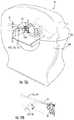
- FIG. 3is a side perspective view of a trajectory guide coupled to a subject that can serially interchangeably hold a targeting cannula and one or more of the components shown in FIG. 2 according to embodiments of the present invention.
- FIG. 4is a side perspective view of the trajectory guide shown in FIG. 3 that slidably couples to the device guide of the devices shown in FIG. 2 according to embodiments of the present invention.
- FIGS. 5A and 5Bare side perspective views of the trajectory guide holding the device shown in FIG. 4 and also coupled to the adapter shown in FIG. 2 according to embodiments of the present invention.
- FIG. 5Cis an enlarged view of the adapter shown in FIG. 2 .
- FIG. 5Dis a section view taken along line 5 D- 5 D in FIG. 5C , according to embodiments of the present invention.
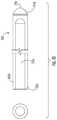
- FIG. 6Ais an enlarged view of the guide sheath shown in FIG. 2 .
- FIG. 6Bis an enlarged view of the guide sheath shown in FIG. 6A coupled to a depth stop according to embodiments of the present invention.
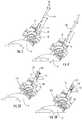
- FIGS. 7A-7Care side perspective views of an exemplary sequence of actions for attaching the guide sheath and stylet to the trajectory guide shown in FIG. 3 according to embodiments of the present invention.
- FIGS. 8A and 8Bare enlarged partial views of the guide sheath and stylet shown in FIGS. 7A-7C illustrating an exemplary detachment sequence of the stylet while the guide sheath remains in position coupled to the trajectory guide according to embodiments of the present invention.
- FIGS. 9A and 9Bare enlarged side perspective views of an exemplary attachment sequence for attaching the guide cannula to the guide sheath held by the trajectory guide according to embodiments of the present invention.
- FIGS. 10A and 10Bare side perspective views of flexible tubing attached at one end to the guide sheath and attached or attachable to a syringe on the other end according to embodiments of the present invention.
- FIG. 11is a section view of an example stylet body according to embodiments of the present invention.
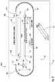
- FIG. 12Ais an end perspective view of a bore of a magnet with a fluid delivery system in position according to embodiments of the present invention.
- FIG. 12Bis a schematic of a portion of the system shown in FIG. 12A illustrating the radius of curvature allowed by the fluid delivery system according to embodiments of the present invention.
- FIG. 13is a schematic illustration of an example screen display of a surgical navigation system shown on a display according to embodiments of the present invention.
- FIG. 14is a flow chart of example actions that can be carried out according to embodiments of the present invention.
- spatially relative termssuch as “under,” “below,” “lower,” “over,” “upper” and the like, may be used herein for ease of description to describe one element or feature's relationship to another element(s) or feature(s) as illustrated in the figures. It will be understood that the spatially relative terms are intended to encompass different orientations of the device in use or operation in addition to the orientation depicted in the figures. For example, if the device in the figures is inverted, elements described as “under” or “beneath” other elements or features would then be oriented “over” the other elements or features. Thus, the exemplary term “under” can encompass both an orientation of “over” and “under”.
- the devicemay be otherwise oriented (rotated 90 degrees or at other orientations) and the spatially relative descriptors used herein interpreted accordingly.
- the terms “upwardly,” “downwardly,” “vertical,” “horizontal” and the likeare used herein for the purpose of explanation only unless specifically indicated otherwise.
- monolithicmeans that the component (e.g., needle) is formed of a single uniform material.
- MRI visiblemeans that a device is visible, directly or indirectly, in an MRI image.
- the visibilitymay be indicated by the increased SNR of the MRI signal proximate to the device (the device can act as an MRI receive antenna to collect signal from local tissue) and/or that the device actually generates MRI signal itself, such as via suitable hydro-based coatings and/or fluid (typically aqueous solutions) filled channels or lumens.
- MRI compatiblemeans that a device is safe for use in an MRI environment and/or can operate as intended in an MRI environment without generating MR signal artifacts, and, as such, if residing within the high-field strength region of the magnetic field, is typically made of a non-ferromagnetic MRI compatible material(s) suitable to reside and/or operate in a high magnetic field environment.
- high-magnetic fieldrefers to field strengths above about 0.5 T (Tesla), typically above 1.0 T, and more typically between about 1.5 T and 10 T, such as 2.0 T and 3.0 T, for example.
- near real timerefers to both low latency and high frame rate. Latency is generally measured as the time from when an event occurs to display of the event (total processing time). For near “real-time” imaging, the frame rate is typically between about 1 fps to about 20 fps, and in some embodiments, between about 3 fps to about 7 fps. The low latency required to be considered “near real time” is generally less than or equal to about 1 second. With respect to imaging, visualizations using near real time MR image data can be presented with a low latency, typically within between about 0.01 ms to less than about 1 second, and with a frame rate that is typically between about 1-20 fps. The MRI-guided interventional system can use the image signal data to dynamically present anatomy and one or more intrabody devices in the visualization in near real-time.
- sterilemeans that a device, kit, and/or packaging meets or exceeds medical/surgical cleanliness guidelines, and typically is free from live bacteria or other microorganisms.
- semi-rigidrefers to devices that have sufficient rigidity to have a self-supporting fixed shape (typically straight linear cylindrical shapes) in the absence of applied bending forces but have sufficient flexibility to be able to bend or deflect without breaking in response to forces applied during insertion into or removal from a trajectory guide, then return to its original self-supporting shape upon removal of the applied force(s).
- the subjectcan be any subject, and may be particularly suitable for animal and/or human subjects for e.g., animal studies and/or veterinarian or human treatments.
- Embodiments of the inventioncan deliver therapies to the spine.
- Embodiments of the inventioncan deliver therapies to treat or stimulate a desired region of the sympathetic nerve chain.
- Other uses, inside or outside the brain, nervous system or spinal cord,include stem cell placement, gene therapy or drug delivery for treating physiological conditions, chemotherapy, drugs including replicating therapy drugs.
- Some embodimentscan be used to treat a patient with one or more tumors.
- fluidwith respect to fluid being withdrawn from a subject refers to soft tissue, foreign matter, biological matter including cellular material and liquid in a subject.
- the term “substance,” as used herein,refers to a gas or liquid for delivery to a subject for treating or facilitating diagnosis of a condition and can include bions, stem cells or other target cells to site-specific regions in the body, such as neurological, nerves or other target sites and the like.
- stem cells and/or other rebuilding cells or immune therapy productscan be delivered into spine, brain or cardiac tissue.
- Embodiments of the inventioncan be used to transfer fluid to or from a heart wall via a minimally invasive MRI guided procedure, while the heart is beating (i.e., not requiring a non-beating heart with the patient on a heart-lung machine). Examples of known stimulation treatments and/or target body regions are described in U.S. Pat. Nos.
- FIG. 1illustrates an MRI-guided interventional system 10 with an MRI scanner 20 , a clinician workstation 30 with at least one image processing circuit 30 c , at least one display 32 , an MRI compatible trajectory guide 50 and a fluid transfer system 100 .
- Embodiments of the fluid transfer system 100can be utilized in a bore 20 b of a magnet 20 M of an MRI scanner 20 of the MRI interventional system 10 .
- the MRI system 10can be provided as an MRI suite 10 S that can have a control room 10 C and a separate magnet room 10 M holding the MR Scanner 20 as is well known. However, there is no requirement for a separate control room in some embodiments.
- MRI suites 10 Scan have a control room 10 C with MRI Scanner operating components such as an RF amplifier and control cabinet and a separate scanner room 10 M holding a (high field) magnet 20 M in which a patient is placed for an MRI procedure.
- MRI suitesare enclosed in a Faraday shield (e.g., RF shielding) in order to electrically isolate sensitive MRI radio receivers and prevent them from picking up RF signals other than those emitted by the patient under examination.
- a Faraday shielde.g., RF shielding
- An RF-shielded wall 10 Rtypically separates the two rooms.
- the RF shieldingcauses at least 100 dB of signal attenuation of signals in the frequency range of 1 Hz to 150 MHz.
- the MRI suite 10 Scan be configured with fiber optic cables that are coupled to a user interface that can allow a user to direct certain operational actions using the display 32 .
- the display 30can reside inside the scanner room 10 M. See, e.g., U.S. Pat. No. 9,610,048, the contents of which are hereby incorporated by reference as if recited in full herein.
- the fluid transfer system 100can be provided as components of a kit 100 k held in one or more packages 101 as shown in FIG. 2 .
- the components shown in FIG. 2can provide an MRI-safe fluid transfer system and when used with a surgical navigation system can allow a surgeon to perform an entire medical procedure in an MRI scanner 20 without requiring transport to another room.
- the fluid transfer system 100can include a device guide 110 , a guide sheath 120 , a stylet 125 slidably and detachably held by the guide sheath 120 , and a cannula 130 coupled to flexible tubing 140 .
- the fluid transfer system 100can also optionally include at least one syringe 170 which may be provided in the kit 100 k or provided separately from the kit 100 k.
- the flexible tubing 140can have a proximal end 140 p and a distal end 140 d .
- the proximal end 140 pcan comprise a connector 142 that can attach to the syringe 170 .
- the distal end 140 dcan include a connector 144 that can attach to the guide sheath 120 .
- the flexible tubing 140 with connectors 142 , 144can be provided in the kit 100 k integrally attached to the cannula 130 as shown. However, the flexible tubing 140 can be provided as a separate component that can be assembled onsite, i.e., for assembly prior to or during a medical procedure.
- the connector 142can be a standard (typically female) luer connector.
- the kit 100 kcan provide the stylet 125 pre-assembled to the guide sheath 120 as shown.
- the kit 100 kcan provide the syringe 170 pre-attached to the proximal end of the tubing 140 or the syringe 170 , if provided in the kit, can be detached from the tubing 140 .
- the fluid transfer system 100can also include an adapter 150 , a depth stop 160 and a ruler 180 .
- the ruler 180can provide graduated scales for positional measurements.
- the ruler 180can be a physical ruler that can be removed from the packaging 101 or the ruler 180 can be provided as graduated markings formed or held on a surface of the packaging 101 .
- All components of the fluid transfer system 100can be made of MRI compatible materials, typically all made of polymeric materials.
- MRI compatible materialsmeans that the materials are non-ferromagnetic and do not magnetically interact with the magnetic field of the magnet.
- the components used in the MR Scanner room 10 Sare non-metallic and do not generate heat due to RF coupling during scanning.
- the components of the kit 100 k that are inserted into the body, i.e., brain, during the medical procedurecan be configured to be clearly visible as voids (see, 220 v , FIG. 13 ) in images 200 generated from an MRI scan, which allows a clinician such as a surgeon to verify that the guide sheath 120 , stylet 125 and/or cannula 130 are placed in a desired position in or at a target intrabody region prior to fluid transfer, such as aspiration.
- a targeting cannula 55can be inserted into the trajectory guide 50 that is coupled to a subject P for selecting a desired intrabody insertion path.
- the targeting cannula 55can be removed (as shown by the arrow) and replaced with the device guide 110 as shown in FIG. 4 .
- the targeting cannula 55 and device guide 110can both comprise outwardly extending lugs 56 , 111 that are slidably received in slots 52 in a tower member 51 of the trajectory guide 50 .
- the guide sheath 120passes through the device guide 110 during insertion into the body, i.e., brain.
- the device guide 110has an open through channel with a diameter that has a close fit with the outer wall of the guide sheath 120 so that the desired intrabody trajectory can be maintained.
- the trajectory guide 50typically provides both X-Y adjustment and pitch and roll adjustment in order to accurately position the targeting cannula 55 and guide sheath 120 at a desired location within a patient.
- the trajectory guide 50can have other configurations and, in some embodiments, can provide only pitch and roll adjustment without X-Y adjustment.
- suitable trajectory guidessee U.S. Pat. No. 8,374,677, and co-pending U.S. patent application Ser. No. 15/934,165, the contents of which are hereby incorporated by reference as if recited in full herein.
- other trajectory guide configurationsmay be used and embodiments of the invention are not limited by the examples of the trajectory guides herein.
- the adapter 150can be attached to the trajectory guide 50 , in place of a removable cap.
- the adapter 150has a sufficiently large inner diameter passage or channel 150 c that allows the guide sheath 110 to slidably fit therethrough while locking the guide sheath 110 to the tower member 51 of the trajectory guide 50 .
- the adapter 150has a lock member 154 (shown as a thumb screw lock) that holds devices in position, i.e., the guide sheath 120 , on the trajectory guide 50 with the distal end 120 d at the desired intrabody depth.
- the adapter 150can have upper and lower lock members 154 , 152 and an open longitudinally extending through channel 150 c .
- the upper lock member 154can cooperate with an elastomeric gasket 250 in the channel 150 c .
- the gasket 250squeezes (compresses) against an outer wall of a device held in the channel 150 c , i.e., the guide sheath 110 , without kinking or denting the guide sheath 110 ( FIG. 5A ).
- the elastomeric gasket 250can also increase a grip force with less tightening of the lock member 154 (i.e., thumb screw) relative to the same lock member without such an elastomeric gasket.
- a 1 ⁇ 4 rotation of the lock member 154can provide about a 1-3 lb tightening/force, i.e., about a 2.7 lb tightening/force, reducing the amount of turns required for sufficient locking/gripping.
- the adapter 150can include a cap 252 with a cylindrical segment that resides in the open channel 150 c .
- the cap 252can have an open channel 252 c aligned with the open channel of the adapter 150 c .
- the cap 252can hold the gasket 250 in place, aligned with the upper lock member 154 .
- the inner wall 252 wcan taper inward from a first diameter at the top of the cap 252 t to a smaller diameter providing a chamfer 253 for piloting alignment of devices during insertion.
- the inner wall 150 w of the adapter body 150 b providing the open channel 150 ccan have an enlarged diameter in the segment holding the gasket 250 relative to the diameter of the open channel 150 c below the gasket 250 .
- the adapter 150can also include a locking tab 255 with a bottom 255 b that engages a circumferentially extending slot 52 in the trajectory guide 50 (tower member 51 ) allowing for a “twist-lock” to affix the adapter 150 to the trajectory guide 50 and the lower lock member 152 can be tightened to secure the adapter 150 to the tower member 51 .
- the adapter 150can have a body 150 b with an inner wall 150 w that can be sized and configured to provide a suitably sized diameter of the open channel 150 c that slidably receives the tower member 51 .
- the stylet 125can have a tip 125 t that is tapered to facilitate atraumatic insertion into the subject.
- the tapercan be over a tip length in a range of about 0.06 inches to 0.11 inches.
- the stylet 125can be hollow or solid, typically with a closed forward or tip end 125 t .
- the stylet 125can be configured to exit the distal end of the guide sheath 120 d a fixed distance that is in a range of about 1 mm to about 5 mm.
- the stylet 125can have a primary extruded polymeric body 125 b with a hollow core 125 c and a closed tip 125 t .
- the stylet 125can have a length that is in a range of 9-13 inches, such as about 12 inches.
- the extruded body 125 bcan be semi-rigid with increased flexibility relative to the cannula 130 and guide sheath 120 and can be formed of PEBAX with an outer diameter that is in a range of about 0.160 inches and 0.212 inches and a wall thickness of about 0.025 inches.
- the guide sheath 120can be inserted into the subject (i.e., brain) to target. It is semi-rigid. It encases or contains the stylet 125 with the stylet tip 125 extending external to the distal end 120 d of the guide sheath 120 .
- the stylet 125can be flexible and can be locked into position in the sheath 120 but can be removed once the surgeon verifies that the sheath 120 and stylet 125 are in the desired position in the target.
- the guide sheath 120can provide a safe working channel in the subject, i.e., brain, allowing the surgeon to insert and remove the cannula 130 as many times as needed without disturbing tissue more than once with the initial placement of the guide sheath 120 .
- the stylet 125locks on to the guide sheath 120 , it can maintain its relative position to the guide sheath 120 even if the guide sheath 120 is retracted or advanced relative to the tower (i.e., tubular) member 51 of the trajectory guide 50 .
- the cannula 130 with flexible tubing 140can be inserted into the guide sheath 120 as a unit so that fluid transfer, i.e., aspiration may be performed.
- the cannula 130 and flexible tubing 140are in fluid communication and form a conduit for transferring fluid, i.e., removing aspirated fluid.
- the cannula 130is semi-rigid. It can lock onto the guide sheath 120 in the same manner as the flexible stylet 125 . This allows the cannula 130 to maintain its relative position to the guide sheath 120 even if the guide sheath 120 is retracted or advanced.
- the cannula 130can have a distal end 130 d that is flat.
- the flexible tubing 140can have a length that is in a range of 1-4 feet long, more typically in a range of about 2 feet to 3 feet.
- the flexible tubing 140is external to the subject P, free of any internal more rigid conduit and, when coupled to the guide sheath 120 while held by the trajectory guide 50 coupled to the subject P, can have a length sufficient to extend out of a bore 20 b of a magnet 20 when the subject is in the magnet, typically with a head of the subject residing proximate one end of the magnet bore 20 b ( FIG. 12A ) but is sufficiently short not to be able to drape to the floor of the scanner room when the patient/subject is on a gantry or bed of the MR Scanner 20 .
- the trajectory guide 50can be mounted to the skull of the subject P and the tubing 140 can extend a distance of between 1-4 feet, allowing a clinician easy access to operate the syringe 170 .
- the targeting cannula 55can be removed (See FIG. 3 ).
- the device guide 110is then inserted into the trajectory guide 50 and locked it into a bottom circumferentially extending slot 52 by twisting it (See FIG. 4 ).
- the adapter 150is attached to the trajectory guide 50 and twisted to engage a (circumferentially extending) slot(s) 52 at the top of the tower member 51 (See FIG. 5A ).
- the lock member 152(shown as a lower lock member, i.e., a bottom thumbscrew) is turned to secure it to the tower member 51 (See FIG. 5B ).
- the guide sheath 120 and stylet 125as an assembly can be obtained from the kit 100 k ( FIG. 2 ).
- a visual confirmationcan be made to confirm that the Stylet tip 125 t is protruding from the distal end 120 d of the guide sheath 120 (See FIG. 6A ).
- the ruler 180FIGS. 2, 6B ) to measure corresponding distance on the guide sheath 120 .
- the depth distance from the stylet tip 125 tcan be measured (See FIG. 6B ).
- the depth stop 160can be placed at the measured distance and locked to guide sheath 120 by tightening a lock member 162 , which can be a thumb screw (See FIG. 6B ).
- the guide sheath 120 and stylet 125 as an assembly 120 acan be inserted into the trajectory guide 50 until the depth stop 160 bottoms out on or against a top surface 150 t of the adapter 150 (See FIGS. 7A and 7B ).
- the upper lock member 154 (optionally a thumb screw) on the adapter 150can be tightened to engage the guide sheath 120 and hold the guide sheath 120 in place (See FIG. 7C ).
- scansmay be performed while the sheath-stylet assembly 120 a or sheath 120 and cannula 130 are in position and/or being inserted.
- An MRI scancan be performed to confirm tip position.
- the stylet 120can have a connector 126 that allows the stylet to be detached from the sheath 120 .
- the connector 126can releasably engage a circumferentially extending hub 122 on a proximal end 120 p of the sheath 120 .
- the connector 126can comprise a clip 126 c with longitudinally extending handles (also interchangeably referred to as “legs”) 127 .
- the longitudinally extending legs 127can extend a distance above the hub 122 .
- the hub 122can have a greater outer diameter than the primary body of the sheath 120 b and the primary body of the stylet 125 b .
- the hub 122can have a radially outwardly extending ledge 122 l that couples to lower ends of the legs 127 .
- a usercan (gently) press against (depress) an upper end portion 127 u of the handles 127 , forcing the lower end portions 127 l to pivot outward and release the hub 122 .
- the stylet 125can be completely pulled out of the guide sheath 120 .
- the cannula 130can now be inserted into the guide sheath 120 until a connector 144 , which can be a clip 144 c , bottoms out on the hub 122 of the guide sheath 120 .
- the connector 144can reside on a distal end of the tubing 140 d or a proximal end of the cannula 130 p .
- the clip 144 ccan lock onto the hub 122 .
- the clip 144 ccan have a common configuration with the stylet clip 126 c .
- the clip 144 ccan have longitudinally extending handles (also interchangeably referred to as “legs”) 147 .
- the longitudinally extending legs 147can extend a distance above the hub 122 in the locked position.
- the hub 122can have a greater outer diameter than the primary body of the cannula 130 b .
- a usercan (gently) press against (depress) an upper end portion 147 u of the handles 147 , forcing the lower end portions 147 l to pivot outward and release the hub 122 .
- the cannula 130can be completely pulled out of the guide sheath 120 .
- the flexible tubing 140can have a standard (female twist-lock) luer connector 142 at the proximal end 140 p .
- a syringe 170(or other evacuation or pressure source) can be attached to the luer connector 142 .
- MR visualizationmay be used to monitor during a fluid transfer such aspiration with the cannula in position attached to the flexible tubing and with the cannula 130 held by the guide sheath 120 which is coupled to the trajectory guide 50 .
- the upper lock member 154can then be retightened.
- the depth stop 160can be repositioned by loosening the lock member 162 and sliding the depth stop up or down then sliding the guide sheath up or down until the depth stop 160 stops on the top of the adapter 150 t .
- the lock member 162 of the depth stop 160can be retightened. The re-positioning of the cannula 130 and/or depth stop 160 can be repeated as many times as desired.
- Embodiments of the inventionovercome typical constraints of performing surgical procedures while the patient is in an MR Scanner.
- the componentsalso have novel designs that promote safety and ease of use.
- Embodiments of the inventionprovide a novel combination of materials and sizing to address the MRI issues.
- the guide sheath 120is semi-rigid. This allows it to maintain appropriate rigidity for accuracy of insertion while also being able to resist being kinked or dented when locked by the lock member 154 . However, the configuration also allows it to bend so that the trajectory guide 50 will not experience a high amount of force in the event of a bore collision. Furthermore, to allow for certain targets, the size can be limited to a maximum outer diameter of 0.260′′ (19 Fr), which is lower than endoscopic trochars used in conventional. The maximal outer diameter may be smaller such as 14 Fr or 16 Fr.
- the cannula 130can be semi-rigid and have MRI compatibility (heat resistant, without magnetic pull, avoiding artifact generation for imaging) and can have sufficient flexibility so it can be slightly bent upon insertion, removal and reinsertion to avoid hitting the inside of the scanner bore.
- the cannula 130can be inserted and removed several times from the sheath 120 to flush it out during a surgical procedure, as desired.
- the selection of material and wall thicknesscan be important to maintain these desired properties, particularly given the size constraints. Different combinations of materials and dimensions may yield too rigid a guide sheath (which may make bore collisions unsafe), or too flexible a guide sheath (which compromises accuracy to target).
- the following tablesillustrate example parameters of an example semi-rigid material. To maintain accuracy to a potentially deep target, it is preferred that there is no more than 3.5 mm of deflection at a target 90 mm from the skull surface (Table 1).
- the 0.15-lb valueis an estimate of lateral force applied by brain tissue during insertion of a device.
- a material with an Elastic Modulus of 1.4-1.6 GPamay be particularly suitable for components in a desired dimensional range according to some particular embodiments, as shown in Table 3.
- the guide sheath 120is made of extruded tubing, such as PEEK tubing, with about a 0.020 inch wall thickness and a length that is in a range of about 8-15 inches, more typically a range of about 9-13 inches.
- the guide sheath 120can have a distal end portion 120 d that is tapered over a short distance of about 0.125 inches to have a smaller outer wall dimension at its tip 120 t relative to the outer wall dimension spaced apart from the tip 120 t .
- the guide sheath 120can have graduated scale of measurement markings 120 m (interchangeably referred to as “measurement indicia”) starting with a value above 0 or 1 (i.e., at 10 cm or greater, shown as starting at 15 cm) residing a distance away from the tip 120 d and extending along at least 25% of its length L, optionally in a range of 10 cm to 40 cm to its proximal end portion ( FIG. 6A ).
- the markings 120 mcan start with a measurement of 15 cm at a position that is 2-6 inches from the distal end 120 d and increase in measurement values toward the proximal end 120 p .
- the guide sheath 120can have a different length than the cannula 130 .
- the guide sheath 120can be shorter than the cannula 130 (and stylet 125 ) in a range of about 1-3 inches, such as about 1 inch to about 2 inches or 3-5 mm, when fully assembled.
- the guide sheath 120can have a maximal size of 19 Fr, such as 12 Fr, 14 Fr or 16 Fr, at least for the intrabody portion.
- Frand “Fr” interchangeably refer to the French scale of size of a catheter as is known to those of skill in the art.
- the guide sheath 120can have an outer diameter in a range of 0.208 inches and 0.260 inches, an inner diameter in a range of 0.168 and 0.220 inches, and a wall thickness of about 0.020 in some embodiments.
- the guide sheath 120can have a length in a range of about 9-13 inches, in some embodiments.
- the stylet 125can be made of 70 D durometer PEBA tubing with 0.025′′ wall thickness that is tipped to create an atraumatic distal end 125 t .
- the stylet 125is sufficiently flexible so that it can be removed from the guide sheath 120 when the subject P is in the scanner bore, but the wall thickness prevents it from kinking when being bent (which would likely prohibit it from being easily withdrawn out of the sheath 120 ). This allows the surgeon to remove the stylet to prepare for cannula insertion without having to move the scanner table out of the bore.
- the stylet 125can also bend without breaking or kinking in the event of the bore collision of the scanner.
- the cannula 130can have a maximal size of 10 F-16 F, such as about 10 Fr, about 12 Fr, about 14 Fr or about 16 Fr, at least for the intrabody portion.
- the cannula 130can be made of (medical grade) polyimide tubing with a wall thickness in a range of about 0.005-0.025 inches, optionally in a range of about 0.009-0.010 inches. Polyimide at this combination of ID and wall thickness is semi-rigid. It provides good rigidity while still being flexible if bent. Again, this is a desirable property, as it allows the surgeon to insert the cannula 130 into the guide sheath 120 , even when the trajectory guide's 50 clearance with the scanner bore 20 b is small.
- the wall thickness of the cannula 30should not be made too thin, as the chance of kinking during bending, thereby obstructing flow, would increase. Also, the wall thickness should be substantial enough so that the wall does not collapse under vacuum pressure during aspiration.
- the cannula 130has a small ID of about 0.138 inches and an outer diameter of about 12 Fr, which allows a good cross-sectional area for efficient aspiration of thick or viscous fluid. If the ID is too small, the suction efficiency may be compromised.
- the cooperating configurations of the guide sheath 120 , the cannula 130 , and the stylet 125promote ease of use and safety.
- the cannula 130 and stylet 125can each have a clip-style connector 126 c , 144 c that allows them to easily lock with and detach from the guide sheath 120 .
- the clips 126 c , 144 ccan be operated single-handedly, and they only require the user to push them over the guide sheath's hub 122 to self-lock. To remove either device from the guide sheath 120 , the user need only squeeze the clip's handles 127 , 147 and retract the device. This allows the user to insert and remove the cannula 130 and stylet 125 single-handedly while the patient is in the scanner bore.
- the stylet tip 125 tprotrudes a set distance, such as a range of 1-5 mm, more typically a range of 3-5 mm, from the distal end 120 d of the sheath 120 .
- the cannula 130is locked into the guide sheath 120 , it protrudes the same amount as the distal end of the stylet 125 t . So, the cannula distal end 130 d is always the same position in the target as the stylet distal end 125 d was.
- aspiration cannulasare made of metal because the procedure is performed in a completely open surgical environment. Therefore, they can be highly rigid, which is an advantage in maintaining accurate placement.
- an interchangeable stylet 125 and cannula 130 systemwhich maintains the position of the respective device tips during exchange.
- the position of the stylet 125 and the cannula 130can always be maintained relative to the guide sheath 120 when they are locked (fully assembled) together. This allows for easy adjustment of the guide sheath 120 when desired, without needing to confirm the position of the cannula 130 or stylet 125 each time a positional adjustment (advance or retraction) is made.
- FIG. 12Aillustrates that the stylet 125 and/or cannula 130 can be semi-rigid so as to be able to bend to have a radius of curvature R from its original straight linear shape, such as upon contact with or to avoid a wall of the bore of the magnet 20 b when mounted to the trajectory guide 50 or upon removal from the trajectory guide 50 . Even if the bore 20 b of the magnet does not contact the top of the cannula 130 or stylet 125 , the flexibility of both components can allow a surgeon to withdraw/insert them from/into the guide sheath 120 while keeping the patient in the current bore position.
- the radius of curvature R of the guide sheath 120can be a maximum of 6.7 cm to allow for curvature of the semi-rigid component to stay within a clearance gap G between a top of the adapter 150 held by the trajectory guide 50 and the wall of the bore that can be a minimum of 7 cm.
- the radius of curvature R of the cannula 130 and stylet 125can be a maximum of 5.0 cm to allow for curvature of these components to be withdrawn/inserted with a clearance gap G 1 (between the top of the guide sheath 120 and the scanner bore 20 b ) that can be a minimum of 5.5 cm.
- the radius of curvature Rcan be measured from a non-bent linear line that is parallel to the tower 52 of the trajectory guide 50 .
- FIG. 13illustrates a display window of a display 32 from a surgical navigation system 1000 and having a user interface 30 UI.
- the image processing circuit 30 ccan calculate, and direct the display 32 to provide, a depth stop measurement output 160 m (depth stop distance) for a user to set the depth stop 160 on the guide sheath 120 .
- the measurement providedcan define a placement of the depth stop 160 at a distance from the stylet tip 125 t ( FIG. 6A ) to the desired location on the guide sheath 120 rather than measured from the distal end of the guide sheath 120 d , in some embodiments.
- the measurement direction provided by the display/image processing circuit 30 ccan allow the user to measure from the distal end of the guide sheath 130 rather than where the stylet tip resides as the cannula distal end extends out of the distal end of the cannula a fixed known distance (i.e., the calculation of the depth stop position on the guide sheath 130 is adjusted for this configuration, as the actual target site reached will be based on the extension distance).
- the display 32can also display images, i.e., MRI images 200 with the guide sheath 120 , cannula 130 and/or stylet 125 shown as voids 220 v in the image(s).
- FIG. 14illustrates an exemplary set of actions that can be used to carry out an MRI-guided medical aspiration procedure.
- a set of components for an MRI guided aspiration medical procedureis provided.
- the set of componentsbeing MRI compatible and comprising: a device guide; a semi-rigid guide sheath with measurement indicia configured to slidably extend through the device guide; a stylet releasable coupled to the guide sheath and extending a fixed distance out of a distal end thereof; and a cannula coupled to flexible tubing (block 500 ).
- the device guideis attached to a trajectory guide mounted to a subject, the trajectory guide defining an entry trajectory axis into the subject to a target site (block 510 ).
- a depth stopis placed at a desired location on the guide sheath, the desired location associated with measurement indicia calculated to place a distal end of the stylet and a distal end of the cannula at the target site when the guide sheath is attached to the trajectory guide (block 520 ).
- the guide sheath and stylet, coupled together as an assembly,are inserted through the open channel of the device guide (block 530 ).
- the styletis removed from the guide sheath and the cannula is then inserted into the guide sheath so that a distal end thereof resides at the target site (block 540 ).
- a syringe or other vacuum sourceis attached to the flexible tubing and fluid from the target site is aspirated through the cannula and the flexible tubing (block 550 ).
- the deviceshave been described herein primarily with reference to MRI-guided insertion and infusion procedures, in some embodiments the devices can be used in procedures without MRI guidance.
Landscapes
- Health & Medical Sciences (AREA)
- Life Sciences & Earth Sciences (AREA)
- Surgery (AREA)
- Engineering & Computer Science (AREA)
- General Health & Medical Sciences (AREA)
- Animal Behavior & Ethology (AREA)
- Biomedical Technology (AREA)
- Heart & Thoracic Surgery (AREA)
- Medical Informatics (AREA)
- Molecular Biology (AREA)
- Pathology (AREA)
- Public Health (AREA)
- Veterinary Medicine (AREA)
- Nuclear Medicine, Radiotherapy & Molecular Imaging (AREA)
- Physics & Mathematics (AREA)
- Oral & Maxillofacial Surgery (AREA)
- Condensed Matter Physics & Semiconductors (AREA)
- General Physics & Mathematics (AREA)
- Gynecology & Obstetrics (AREA)
- Radiology & Medical Imaging (AREA)
- Robotics (AREA)
- Magnetic Resonance Imaging Apparatus (AREA)
Abstract
Description
| TABLE 1 | ||
| Maximum | Applied Load | Distance from |
| Deflection (mm) | (lb) | supported end (mm) |
| 2.5 | .15 | 90 |
| TABLE 2 | ||
| Distance from | ||
| Minimum Deflection (mm) | Applied Load (lb) | supported end (mm) |
| 20 | 4.0 | 90 |
| TABLE 3 | |||||
| Deflection (mm) | Deflection (mm) | ||||
| OD (in) | ID (in) | @ 0.15 lb, 90 mm | @ 4.0 lb, 90 mm | ||
| 0.260 | .220 | 1.1 | 29 | ||
| .233 | .193 | 1.6 | 42 | ||
| .208 | .188 | 2.3 | 60 | ||
Claims (10)
Priority Applications (2)
| Application Number | Priority Date | Filing Date | Title |
|---|---|---|---|
| US16/217,222US11022664B2 (en) | 2018-05-09 | 2018-12-12 | MRI compatible intrabody fluid transfer systems and related devices and methods |
| US17/245,470US20210255261A1 (en) | 2018-05-09 | 2021-04-30 | Mri compatible intrabody fluid transfer systems and related devices and methods |
Applications Claiming Priority (2)
| Application Number | Priority Date | Filing Date | Title |
|---|---|---|---|
| US201862668914P | 2018-05-09 | 2018-05-09 | |
| US16/217,222US11022664B2 (en) | 2018-05-09 | 2018-12-12 | MRI compatible intrabody fluid transfer systems and related devices and methods |
Related Child Applications (1)
| Application Number | Title | Priority Date | Filing Date |
|---|---|---|---|
| US17/245,470DivisionUS20210255261A1 (en) | 2018-05-09 | 2021-04-30 | Mri compatible intrabody fluid transfer systems and related devices and methods |
Publications (2)
| Publication Number | Publication Date |
|---|---|
| US20190346516A1 US20190346516A1 (en) | 2019-11-14 |
| US11022664B2true US11022664B2 (en) | 2021-06-01 |
Family
ID=65237129
Family Applications (2)
| Application Number | Title | Priority Date | Filing Date |
|---|---|---|---|
| US16/217,222Expired - Fee RelatedUS11022664B2 (en) | 2018-05-09 | 2018-12-12 | MRI compatible intrabody fluid transfer systems and related devices and methods |
| US17/245,470AbandonedUS20210255261A1 (en) | 2018-05-09 | 2021-04-30 | Mri compatible intrabody fluid transfer systems and related devices and methods |
Family Applications After (1)
| Application Number | Title | Priority Date | Filing Date |
|---|---|---|---|
| US17/245,470AbandonedUS20210255261A1 (en) | 2018-05-09 | 2021-04-30 | Mri compatible intrabody fluid transfer systems and related devices and methods |
Country Status (3)
| Country | Link |
|---|---|
| US (2) | US11022664B2 (en) |
| EP (1) | EP3781074A1 (en) |
| WO (1) | WO2019216953A1 (en) |
Cited By (3)
| Publication number | Priority date | Publication date | Assignee | Title |
|---|---|---|---|---|
| US11541207B2 (en) | 2016-02-17 | 2023-01-03 | Clearpoint Neuro, Inc. | Intrabody surgical fluid transfer assemblies with adjustable exposed cannula to needle tip length, related systems and methods |
| US11684750B2 (en) | 2019-10-08 | 2023-06-27 | Clearpoint Neuro, Inc. | Extension tube assembly and related medical fluid transfer systems and methods |
| US11793933B2 (en) | 2010-04-16 | 2023-10-24 | Clearpoint Neuro, Inc. | MRI-compatible surgical cannulae for transferring a substance to and/or from a patient |
Families Citing this family (6)
| Publication number | Priority date | Publication date | Assignee | Title |
|---|---|---|---|---|
| JP2019531787A (en) | 2016-08-30 | 2019-11-07 | ザ リージェンツ オブ ザ ユニバーシティ オブ カリフォルニア | Biomedical targeting and delivery method and apparatus and system for performing the same |
| CN111132626B (en) | 2017-07-17 | 2024-01-30 | 沃雅戈治疗公司 | track array guidance system |
| EP3781074A1 (en) | 2018-05-09 | 2021-02-24 | ClearPoint Neuro, Inc. | Mri compatible intrabody fluid transfer systems and related devices and methods |
| US11253237B2 (en) | 2018-05-09 | 2022-02-22 | Clearpoint Neuro, Inc. | MRI compatible intrabody fluid transfer systems and related devices and methods |
| JP7608463B2 (en) | 2019-12-19 | 2025-01-06 | クリアポイント ニューロ, インク. | FRONT LOADABLE FLUID TRANSFER ASSEMBLY AND ASSOCIATED MEDICAL FLUID TRANSFER SYSTEMS AND METHODS - Patent application |
| WO2024097890A2 (en)* | 2022-11-02 | 2024-05-10 | Monteris Medical Corporation | Cranial access assembly and method of using the same |
Citations (169)
| Publication number | Priority date | Publication date | Assignee | Title |
|---|---|---|---|---|
| US3352306A (en) | 1963-12-23 | 1967-11-14 | Hrisch Sidney | Intravenous catheter assembly |
| US3540447A (en) | 1967-09-29 | 1970-11-17 | Becton Dickinson Co | Spinal needle |
| GB1255551A (en) | 1968-03-30 | 1971-12-01 | Heraeus Schott Quarzschmelze | Improvements in or relating to externally coated fused silica tube |
| US3824157A (en) | 1971-01-29 | 1974-07-16 | Gen Electric | Method of equilibrating and calibrating a partial pressure gas sensor |
| US3856009A (en) | 1971-11-26 | 1974-12-24 | Johnson & Johnson | Catheter placement unit |
| US4149535A (en) | 1976-05-06 | 1979-04-17 | Gist-Brocades N.V. | Catheter holding device |
| US4239042A (en) | 1979-04-05 | 1980-12-16 | Dow Corning K.K. | Catheter placement system |
| US4265928A (en) | 1978-10-06 | 1981-05-05 | Intermedicat Gmbh | Anti-thrombogenic retentive catheter |
| US4327722A (en) | 1979-08-20 | 1982-05-04 | Groshong Leroy E | Methods and apparatus for intravenous therapy and hyperalimentation |
| US4449532A (en) | 1980-07-08 | 1984-05-22 | Karl Storz | Dilator to facilitate endoscope insertion into the body |
| US4531943A (en) | 1983-08-08 | 1985-07-30 | Angiomedics Corporation | Catheter with soft deformable tip |
| US4543091A (en) | 1983-05-18 | 1985-09-24 | Edward C. Froning | X-ray marker device |
| US4543092A (en) | 1982-08-06 | 1985-09-24 | Doron Mehler | Catheter set |
| US4597421A (en) | 1984-11-19 | 1986-07-01 | Varian Associates, Inc. | Method and device for on-column injection of a liquid sample into small diameter columns |
| US4623789A (en) | 1983-03-10 | 1986-11-18 | Shionogi & Co., Ltd. | Fiberoptic probe for brain scanning with detachable cannula guide |
| US4629450A (en) | 1984-05-09 | 1986-12-16 | Terumo Corporation | Catheter introducing instrument |
| US4705511A (en) | 1985-05-13 | 1987-11-10 | Bipore, Inc. | Introducer sheath assembly |
| US4738658A (en) | 1986-09-19 | 1988-04-19 | Aries Medical Incorporated | Tapered hemostatic device for use in conjunction with a catheter for alleviating blood leakage and method for using same |
| US4739768A (en) | 1986-06-02 | 1988-04-26 | Target Therapeutics | Catheter for guide-wire tracking |
| US4781691A (en) | 1987-07-17 | 1988-11-01 | The Kendall Company | Stepped needle |
| US4820349A (en) | 1987-08-21 | 1989-04-11 | C. R. Bard, Inc. | Dilatation catheter with collapsible outer diameter |
| US4846799A (en) | 1986-10-09 | 1989-07-11 | Hakko Electric Machine Works Co., Ltd. | Set of double needles for injecting liquid medicine |
| US4897077A (en) | 1987-05-22 | 1990-01-30 | Kontron Inc. | Method of inserting an IAB device into the body |
| US4955863A (en) | 1986-02-05 | 1990-09-11 | Menlo Care, Inc. | Adjustable catheter assembly |
| US4978334A (en) | 1988-09-08 | 1990-12-18 | Toye Frederic J | Apparatus and method for providing passage into body viscus |
| US4995866A (en) | 1989-12-15 | 1991-02-26 | Microvena Corporation | Combined needle and dilator apparatus |
| US5069673A (en) | 1990-02-07 | 1991-12-03 | Cordis Corporation | Catheter with double step-down bore |
| US5380292A (en) | 1993-12-22 | 1995-01-10 | Wilson-Cook Medical, Inc. | Gastrointestinal needle mechanism |
| US5562626A (en) | 1995-09-11 | 1996-10-08 | Sanpietro; Joseph A. | Safety syringe |
| US5699801A (en) | 1995-06-01 | 1997-12-23 | The Johns Hopkins University | Method of internal magnetic resonance imaging and spectroscopic analysis and associated apparatus |
| US5720720A (en) | 1993-08-27 | 1998-02-24 | The United States Of America As Represented By The Department Of Health And Human Services | Convection-enhanced drug delivery |
| US5722985A (en) | 1996-12-27 | 1998-03-03 | Pettus; William G. | Instrument for tumor therapy |
| US5792144A (en) | 1997-03-31 | 1998-08-11 | Cathco, Inc. | Stent delivery catheter system |
| US5833662A (en) | 1995-01-19 | 1998-11-10 | Stevens; Robert C. | Hemostasis cannula system |
| US5851203A (en) | 1993-09-22 | 1998-12-22 | Cordis Corporation | Neuro-microcatheter |
| US5857999A (en) | 1995-05-05 | 1999-01-12 | Imagyn Medical Technologies, Inc. | Small diameter introducer for laparoscopic instruments |
| WO1999004849A1 (en) | 1997-07-25 | 1999-02-04 | The Regents Of The University Of California | Retroperfusion catheter apparatus and method |
| US5871470A (en) | 1997-04-18 | 1999-02-16 | Becton Dickinson And Company | Combined spinal epidural needle set |
| US5902282A (en) | 1996-12-26 | 1999-05-11 | Johnson & Johnson Medical, Inc. | Step-down catheter |
| US5919171A (en) | 1994-08-03 | 1999-07-06 | Kanegafuchi Kagaku Kogyo Kabushiki Kaisha | Microcatheter |
| US5928145A (en) | 1996-04-25 | 1999-07-27 | The Johns Hopkins University | Method of magnetic resonance imaging and spectroscopic analysis and associated apparatus employing a loopless antenna |
| US5935122A (en) | 1991-12-13 | 1999-08-10 | Endovascular Technologies, Inc. | Dual valve, flexible expandable sheath and method |
| WO1999049909A2 (en) | 1998-03-27 | 1999-10-07 | Brigham & Women's Hospital, Inc. | Revascularization apparatus having coaxial channeling and injecting means |
| US6020196A (en) | 1996-05-09 | 2000-02-01 | Baxter International Inc. | Devices for harvesting and homogenizing adipose tissue containing autologous endothelial cells |
| US6026316A (en) | 1997-05-15 | 2000-02-15 | Regents Of The University Of Minnesota | Method and apparatus for use with MR imaging |
| US6030369A (en) | 1997-07-03 | 2000-02-29 | Target Therapeutics Inc. | Micro catheter shaft |
| US6042579A (en) | 1997-04-30 | 2000-03-28 | Medtronic, Inc. | Techniques for treating neurodegenerative disorders by infusion of nerve growth factors into the brain |
| US6050992A (en) | 1997-05-19 | 2000-04-18 | Radiotherapeutics Corporation | Apparatus and method for treating tissue with multiple electrodes |
| US6093180A (en) | 1995-04-28 | 2000-07-25 | Medtronic, Inc. | Intraparenchymal infusion catheter system |
| EP1029509A1 (en) | 1999-02-19 | 2000-08-23 | Magnetic Vision GmbH | Device for cutting and aspirating tissue |
| US6167311A (en) | 1999-06-14 | 2000-12-26 | Electro Core Techniques, Llc | Method of treating psychological disorders by brain stimulation within the thalamus |
| US6186986B1 (en) | 1998-01-21 | 2001-02-13 | St. Jude Medical Cardiovascular Group, Inc. | Micro-catheters and methods of their manufacture |
| US6231591B1 (en) | 1991-10-18 | 2001-05-15 | 2000 Injectx, Inc. | Method of localized fluid therapy |
| US6263229B1 (en) | 1998-11-13 | 2001-07-17 | Johns Hopkins University School Of Medicine | Miniature magnetic resonance catheter coils and related methods |
| US6284971B1 (en) | 1998-11-25 | 2001-09-04 | Johns Hopkins University School Of Medicine | Enhanced safety coaxial cables |
| USRE37410E1 (en) | 1994-08-02 | 2001-10-16 | Massachusetts Institute Of Technology | Controlled local delivery of chemotherapeutic agents for treating solid tumors |
| US6309634B1 (en) | 1998-05-27 | 2001-10-30 | Avigen, Inc. | Methods of treating Parkinson's disease using recombinant adeno-associated vector (rAAV) |
| US6336915B1 (en) | 1997-01-08 | 2002-01-08 | Symbiosis Corporation | Endoscopic infusion needle having dual distal stops |
| US6356786B1 (en) | 2000-01-20 | 2002-03-12 | Electrocore Techniques, Llc | Method of treating palmar hyperhydrosis by electrical stimulation of the sympathetic nervous chain |
| US6405079B1 (en) | 2000-09-22 | 2002-06-11 | Mehdi M. Ansarinia | Stimulation method for the dural venous sinuses and adjacent dura for treatment of medical conditions |
| US20020087152A1 (en) | 2001-01-04 | 2002-07-04 | Endocare, Inc. | Systems and methods for delivering a probe into tissue |
| US20020091372A1 (en) | 2001-01-09 | 2002-07-11 | Andrew Cragg | Micro catheter and guidewire system having improved pushability and control |
| US20020095081A1 (en) | 1995-09-28 | 2002-07-18 | Brainlab Med. Computersysteme Gmbh | Neuro-navigation system |
| US6438423B1 (en) | 2000-01-20 | 2002-08-20 | Electrocore Technique, Llc | Method of treating complex regional pain syndromes by electrical stimulation of the sympathetic nerve chain |
| US20020114780A1 (en) | 2000-11-30 | 2002-08-22 | Krys Bankiewicz | Methods of increasing distribution of therapeutic agents |
| US6461296B1 (en) | 1998-06-26 | 2002-10-08 | 2000 Injectx, Inc. | Method and apparatus for delivery of genes, enzymes and biological agents to tissue cells |
| US20020183763A1 (en) | 2001-05-17 | 2002-12-05 | Callol Joseph R. | Stent and catheter assembly and method for treating bifurcations |
| US20030028095A1 (en) | 1999-04-15 | 2003-02-06 | Steve Tulley | Magnetic resonance imaging probe |
| US6526318B1 (en) | 2000-06-16 | 2003-02-25 | Mehdi M. Ansarinia | Stimulation method for the sphenopalatine ganglia, sphenopalatine nerve, or vidian nerve for treatment of medical conditions |
| US6524299B1 (en) | 1997-04-09 | 2003-02-25 | Target Therapeutics, Inc. | Flow-directed catheter |
| US20030050557A1 (en) | 1998-11-04 | 2003-03-13 | Susil Robert C. | Systems and methods for magnetic-resonance-guided interventional procedures |
| US6539263B1 (en) | 1999-06-11 | 2003-03-25 | Cornell Research Foundation, Inc. | Feedback mechanism for deep brain stimulation |
| US20030073934A1 (en) | 2001-10-17 | 2003-04-17 | David A. Putz | Double slotted-cannula device and method of use |
| US6551290B1 (en) | 2000-03-31 | 2003-04-22 | Medtronic, Inc. | Catheter for target specific drug delivery |
| US6585694B1 (en) | 2000-09-07 | 2003-07-01 | Syntheon, Llc | Knob-controlled endoscopic needle device |
| US20030130575A1 (en) | 1991-10-18 | 2003-07-10 | Ashvin Desai | Method and apparatus for tissue treatment with laser and electromagnetic radiation |
| US6606513B2 (en) | 2000-02-01 | 2003-08-12 | Surgi-Vision, Inc. | Magnetic resonance imaging transseptal needle antenna |
| EP1334740A1 (en) | 2002-02-11 | 2003-08-13 | Sergio Restelli | Glass safety syringe and relative safety kit for glass syringe |
| US6609030B1 (en) | 2000-02-24 | 2003-08-19 | Electrocore Techniques, Llc | Method of treating psychiatric diseases by neuromodulation within the dorsomedial thalamus |
| WO2003077785A1 (en) | 2002-03-12 | 2003-09-25 | Steven Streatfield Gill | Catheter and guide tube for intracerebral application |
| US6628980B2 (en) | 2000-03-24 | 2003-09-30 | Surgi-Vision, Inc. | Apparatus, systems, and methods for in vivo magnetic resonance imaging |
| US6641555B1 (en) | 1997-11-12 | 2003-11-04 | Mdc Investment Holdings, Inc. | Fluid collection device with captured retractable needle |
| US6641564B1 (en) | 2000-11-06 | 2003-11-04 | Medamicus, Inc. | Safety introducer apparatus and method therefor |
| US20030216714A1 (en) | 2002-04-30 | 2003-11-20 | Gill Steven Streatfield | Pump |
| US6675033B1 (en) | 1999-04-15 | 2004-01-06 | Johns Hopkins University School Of Medicine | Magnetic resonance imaging guidewire probe |
| US6689142B1 (en) | 1999-04-26 | 2004-02-10 | Scimed Life Systems, Inc. | Apparatus and methods for guiding a needle |
| US6701176B1 (en) | 1998-11-04 | 2004-03-02 | Johns Hopkins University School Of Medicine | Magnetic-resonance-guided imaging, electrophysiology, and ablation |
| US20040044329A1 (en) | 2002-08-29 | 2004-03-04 | Trudell Leonard A. | Catheter for cardiac injection and method for delivery of therapeutic agents to specified tissues |
| US20040046557A1 (en) | 2002-05-29 | 2004-03-11 | Parag Karmarkar | Magnetic resonance probes |
| US6708064B2 (en) | 2000-02-24 | 2004-03-16 | Ali R. Rezai | Modulation of the brain to affect psychiatric disorders |
| US20040064098A1 (en) | 2001-01-05 | 2004-04-01 | Alfred Cuschieri | Hypodermic needle and fluid injection device |
| US20040068190A1 (en) | 2002-10-04 | 2004-04-08 | Cespedes Eduardo Ignacio | Imaging catheter with indicia and methods of use |
| WO2004031348A2 (en) | 2002-09-24 | 2004-04-15 | The Government Of The United States Of America As Represented By The Secretary Of The Department Of Health And Human Services | Method for convection enhanced delivery of therapeutic agents |
| US20040092879A1 (en) | 2000-11-06 | 2004-05-13 | Medamicus, Inc. | Safety introducer apparatus and method therefor |
| JP2004147830A (en) | 2002-10-30 | 2004-05-27 | Jfe Steel Kk | Ceramic coated needle for gene control, method for producing the same, and apparatus for producing the same |
| US20040199129A1 (en) | 2003-04-07 | 2004-10-07 | Scimed Life Systems, Inc. | Vascular access port |
| US20040209810A1 (en) | 2003-02-24 | 2004-10-21 | Gill Steven S. | Method of treating Parkinson's disease in humans by intraputaminal infusion of glial cell-line derived neurotrophic factor |
| US20040215162A1 (en) | 2003-04-25 | 2004-10-28 | Ad-Tech Medical Instrument Corp. | Intracranial catheter assembly for precise treatment of brain tissue |
| US20040249261A1 (en) | 2001-06-15 | 2004-12-09 | Torchia Mark G. | Hyperthermia treatment and probe therefor |
| EP1491154A1 (en) | 2002-01-22 | 2004-12-29 | JFE Steel Corporation | Ceramic-coated instruments for medical use, ceramic-coated instruments for studying living organisms and process for producing the same |
| US20050004504A1 (en) | 2003-06-24 | 2005-01-06 | Frye Mark R. | Catheter for extracorporeal treatment |
| US20050112065A1 (en) | 2003-07-09 | 2005-05-26 | Drummond Daryl C. | Remote detection of substance delivery to cells |
| US20050148865A1 (en) | 2001-11-09 | 2005-07-07 | Scimed Life Systems, Inc. | Ceramic reinforcement member for MRI devices |
| US20050256503A1 (en) | 2002-05-07 | 2005-11-17 | Cardiac Pacemakers, Inc. | Tapered catheter delivery system |
| US20060052750A1 (en) | 2004-09-09 | 2006-03-09 | Jay Lenker | Expandable transluminal sheath |
| US7037295B2 (en) | 1999-12-16 | 2006-05-02 | Advanced Cardiovascular Systems, Inc. | Co-extruded taper shaft |
| US20060129126A1 (en) | 2004-11-19 | 2006-06-15 | Kaplitt Michael G | Infusion device and method for infusing material into the brain of a patient |
| US20060135945A1 (en)* | 2004-10-05 | 2006-06-22 | Avigen, Inc., The Regents Of The University Of California | Stepped cannula |
| US20060217664A1 (en) | 2004-11-15 | 2006-09-28 | Hattler Brack G | Telescoping vascular dilator |
| US7182944B2 (en) | 2001-04-25 | 2007-02-27 | The United States Of America As Represented By The Department Of Health And Human Services | Methods of increasing distribution of nucleic acids |
| US20070088295A1 (en) | 2005-08-23 | 2007-04-19 | Bankiewicz Krystof S | Reflux resistant cannula and system for chronic delivery of therapeutic agents using convection-enhanced delivery |
| US20070110798A1 (en) | 2004-05-03 | 2007-05-17 | Hermes Biosciences, Inc. | Liposomes useful for drug delivery to the brain |
| US20070167736A1 (en) | 2004-05-21 | 2007-07-19 | Dietz Timothy G | MRI biopsy apparatus incorporating an imageable penetrating portion |
| US20070179455A1 (en) | 2005-12-16 | 2007-08-02 | David Geliebter | Needle constructed with a transparent or translucent material |
| US20070250021A1 (en) | 2002-10-10 | 2007-10-25 | Becton, Dickinson And Company | System and method of delivering local anesthesia |
| US20070254842A1 (en) | 2006-04-25 | 2007-11-01 | The Regents Of The University Of California | Administration of growth factors for the treatment of cns disorders |
| US7329262B2 (en) | 2002-03-12 | 2008-02-12 | Renishaw Plc | Stereoguide for clamping neurosurgical instruments |
| WO2008020237A2 (en) | 2006-08-18 | 2008-02-21 | Renishaw Plc | Neurological apparatus |
| US20080103456A1 (en) | 2006-10-30 | 2008-05-01 | Johnson Benjamin A | Infusion catheter |
| US20080119821A1 (en) | 2006-11-17 | 2008-05-22 | Warsaw Orthopedic, Inc. | Multiport Cannula |
| US20080215008A1 (en) | 2006-12-20 | 2008-09-04 | Nance Edward J | Expandable trans-septal sheath |
| US20080228168A1 (en) | 2007-03-16 | 2008-09-18 | Stephan Mittermeyer | Catheter with changing material properties |
| WO2008144775A1 (en) | 2007-05-23 | 2008-11-27 | Biosense Webster, Inc. | Extension control handle with adjustable locking mechanism |
| WO2008144585A1 (en) | 2007-05-17 | 2008-11-27 | Medgenesis Therapeutix Inc. | Convection-enhanced delivery catheter with removable stiffening member and method for using same |
| US20080319377A1 (en) | 2004-05-04 | 2008-12-25 | James Keenan | Medical Device for Generating Transient Bubbles |
| US20090088695A1 (en) | 2007-09-28 | 2009-04-02 | Codman & Shurtleff, Inc. | Catheter for reduced reflux in targeted tissue delivery of a therapeutic agent |
| WO2009042135A2 (en) | 2007-09-24 | 2009-04-02 | Surgivision, Inc. | Mri surgical systems for real-time visualizations using mri image data and predefined data of surgical tools |
| US20090088730A1 (en) | 2007-09-28 | 2009-04-02 | Codman & Shurtleff, Inc. | Catheter for reduced reflux in targeted tissue delivery of a therapeutic agent |
| WO2009047490A2 (en) | 2007-10-08 | 2009-04-16 | Renishaw Plc | Catheter |
| US20090112084A1 (en) | 2007-06-07 | 2009-04-30 | Surgi-Vision, Inc. | Mri-guided medical interventional systems and methods |
| US20090118610A1 (en) | 2005-11-29 | 2009-05-07 | Karmarkar Parag V | Mri-guided localization and/or lead placement systems, related methods, devices and computer program products |
| WO2009066130A1 (en) | 2007-11-21 | 2009-05-28 | Becton Dickinson France | Injection device preventing the return of the piston when the safety systems is deployed |
| US20090143764A1 (en) | 2007-11-30 | 2009-06-04 | Medtronic, Inc. | Infusion catheter assembly with reduced backflow |
| US20090171184A1 (en) | 2007-09-24 | 2009-07-02 | Surgi-Vision | Mri surgical systems for real-time visualizations using mri image data and predefined data of surgical tools |
| WO2009101397A1 (en) | 2008-02-13 | 2009-08-20 | Renishaw Plc | Catheter |
| US20090209937A1 (en) | 2007-08-11 | 2009-08-20 | Argenis Llc | Apparatus and Methods for Treating Epilepsy Using Convection-Enhanced Delivery |
| US20090281453A1 (en) | 2004-05-21 | 2009-11-12 | Ethicon Endo-Surgery, Inc. | MRI Biopsy Apparatus Incorporating a Sleeve and Multi-Function Obturator |
| WO2010040970A2 (en) | 2008-10-08 | 2010-04-15 | Renishaw (Ireland) Limited | Catheter |
| US20100130958A1 (en) | 2008-11-26 | 2010-05-27 | David Kang | Device and Methods for Subcutaneous Delivery of High Viscosity Fluids |
| US20100198052A1 (en) | 2009-01-28 | 2010-08-05 | Kimble Jenkins | Mri-compatible articulating arms and related systems and methods |
| US7780692B2 (en) | 2003-12-05 | 2010-08-24 | Onset Medical Corporation | Expandable percutaneous sheath |
| CA2655515A1 (en) | 2009-02-25 | 2010-08-25 | Imris Inc. | Temperature sensing within a patient during mr imaging |
| US20100228122A1 (en) | 2005-10-27 | 2010-09-09 | Artenga Inc. | Microbubble medical devices |
| US20100317961A1 (en) | 2009-06-16 | 2010-12-16 | Jenkins Kimble L | MRI-Guided Devices and MRI-Guided Interventional Systems that can Track and Generate Dynamic Visualizations of the Devices in near Real Time |
| US7951110B2 (en) | 2008-11-10 | 2011-05-31 | Onset Medical Corporation | Expandable spinal sheath and method of use |
| WO2011098769A1 (en) | 2010-02-12 | 2011-08-18 | Renishaw (Ireland) Limited | Percutaneous drug delivery apparatus |
| US8195272B2 (en) | 2007-09-24 | 2012-06-05 | MRI Interventions, Inc. | MRI-compatible patches and methods for using the same |
| US8340743B2 (en) | 2007-11-21 | 2012-12-25 | MRI Interventions, Inc. | Methods, systems and computer program products for positioning a guidance apparatus relative to a patient |
| WO2012178169A2 (en) | 2011-06-24 | 2012-12-27 | Ucb Pharma S.A. | Syringe safety assembly |
| US20130030408A1 (en) | 2010-04-16 | 2013-01-31 | Peter Piferi | Mri surgical systems including mri-compatible surgical cannulae for transferring a substance to and/or from a patient |
| WO2013050148A1 (en) | 2011-10-04 | 2013-04-11 | Renishaw (Ireland) Limited | Neurosurgical apparatus |
| US20130150712A1 (en) | 2007-11-15 | 2013-06-13 | Smiths Medical International Limited | Assemblies and methods |
| US20130226094A1 (en) | 2012-02-28 | 2013-08-29 | Cook Medical Technologies Llc | Introducer assembly |
| US8597277B2 (en) | 2004-09-09 | 2013-12-03 | Onset Medical Corporation | Expandable transluminal sheath |
| WO2014089373A1 (en) | 2012-12-05 | 2014-06-12 | University Of Rochester | Catheter with integrated transeptal puncture needle |
| US8900214B2 (en) | 2007-03-30 | 2014-12-02 | Onset Medical Corporation | Expandable trans-septal sheath |
| US20150080708A1 (en)* | 2013-09-13 | 2015-03-19 | MRl lnterventions, Inc. | Intrabody fluid transfer devices, systems and methods |
| US9050419B2 (en) | 2009-09-14 | 2015-06-09 | Circulite, Inc. | Endovascular anastomotic connector device, delivery system, and methods of delivery and use |
| US20160074626A1 (en) | 2014-09-15 | 2016-03-17 | Ethicon, Inc. | System and Method for Targeted Delivery of Therapeutic Agents to Tissue |
| US20160100895A1 (en) | 2014-10-03 | 2016-04-14 | MRI Interventions, Inc. | Split-guides for trajectory frames for medical interventional systems and methods |
| US20160213312A1 (en) | 2015-01-26 | 2016-07-28 | Alcyone Lifesciences, Inc. | Drug delivery methods with tracer |
| US9498575B2 (en) | 2013-03-14 | 2016-11-22 | MRI Interventions, Inc. | Substance delivery devices, systems and methods |
| US9610048B2 (en) | 2012-08-09 | 2017-04-04 | MRI Interventions, Inc. | Fiber optic systems for MRI suites and related devices and methods |
| US20170197017A1 (en) | 2014-07-08 | 2017-07-13 | The Regents Of The University Of California | Image-guided irrigating suction cannula for removal of intracerebral hemorrhage and other lesions |
| US20170232229A1 (en) | 2016-02-17 | 2017-08-17 | MRI Interventions, Inc. | Intrabody surgical fluid transfer assemblies with adjustable exposed cannula to needle tip length, related systems and methods |
| US20180303560A1 (en) | 2017-04-21 | 2018-10-25 | MRI Interventions, Inc. | Surgical navigation systems and related methods |
| WO2019030761A1 (en) | 2017-08-09 | 2019-02-14 | Accurate Medical Therapeutics Ltd. | Microcatheter |
| US20190255282A1 (en) | 2018-02-20 | 2019-08-22 | Terumo Kabushiki Kaisha | Method for manufacturing catheter and catheter manufactured by this manufacturing method |
| US20190346516A1 (en) | 2018-05-09 | 2019-11-14 | MRI Interventions, Inc. | Mri compatible intrabody fluid transfer systems and related devices and methods |
- 2018
- 2018-12-12EPEP18840104.6Apatent/EP3781074A1/ennot_activeWithdrawn
- 2018-12-12USUS16/217,222patent/US11022664B2/ennot_activeExpired - Fee Related
- 2018-12-12WOPCT/US2018/065074patent/WO2019216953A1/ennot_activeCeased
- 2021
- 2021-04-30USUS17/245,470patent/US20210255261A1/ennot_activeAbandoned
Patent Citations (209)
| Publication number | Priority date | Publication date | Assignee | Title |
|---|---|---|---|---|
| US3352306A (en) | 1963-12-23 | 1967-11-14 | Hrisch Sidney | Intravenous catheter assembly |
| US3540447A (en) | 1967-09-29 | 1970-11-17 | Becton Dickinson Co | Spinal needle |
| GB1255551A (en) | 1968-03-30 | 1971-12-01 | Heraeus Schott Quarzschmelze | Improvements in or relating to externally coated fused silica tube |
| US3824157A (en) | 1971-01-29 | 1974-07-16 | Gen Electric | Method of equilibrating and calibrating a partial pressure gas sensor |
| US3856009A (en) | 1971-11-26 | 1974-12-24 | Johnson & Johnson | Catheter placement unit |
| US4149535A (en) | 1976-05-06 | 1979-04-17 | Gist-Brocades N.V. | Catheter holding device |
| US4265928A (en) | 1978-10-06 | 1981-05-05 | Intermedicat Gmbh | Anti-thrombogenic retentive catheter |
| US4239042A (en) | 1979-04-05 | 1980-12-16 | Dow Corning K.K. | Catheter placement system |
| US4327722A (en) | 1979-08-20 | 1982-05-04 | Groshong Leroy E | Methods and apparatus for intravenous therapy and hyperalimentation |
| US4449532A (en) | 1980-07-08 | 1984-05-22 | Karl Storz | Dilator to facilitate endoscope insertion into the body |
| US4543092A (en) | 1982-08-06 | 1985-09-24 | Doron Mehler | Catheter set |
| US4623789A (en) | 1983-03-10 | 1986-11-18 | Shionogi & Co., Ltd. | Fiberoptic probe for brain scanning with detachable cannula guide |
| US4543091A (en) | 1983-05-18 | 1985-09-24 | Edward C. Froning | X-ray marker device |
| US4531943A (en) | 1983-08-08 | 1985-07-30 | Angiomedics Corporation | Catheter with soft deformable tip |
| US4629450A (en) | 1984-05-09 | 1986-12-16 | Terumo Corporation | Catheter introducing instrument |
| US4597421A (en) | 1984-11-19 | 1986-07-01 | Varian Associates, Inc. | Method and device for on-column injection of a liquid sample into small diameter columns |
| US4705511A (en) | 1985-05-13 | 1987-11-10 | Bipore, Inc. | Introducer sheath assembly |
| US4955863A (en) | 1986-02-05 | 1990-09-11 | Menlo Care, Inc. | Adjustable catheter assembly |
| US4739768A (en) | 1986-06-02 | 1988-04-26 | Target Therapeutics | Catheter for guide-wire tracking |
| US4739768B1 (en) | 1986-06-02 | 1994-11-15 | Target Therapeutics Inc | Catheter for guide-wire tracking |
| US4739768B2 (en) | 1986-06-02 | 1995-10-24 | Target Therapeutics Inc | Catheter for guide-wire tracking |
| US4738658A (en) | 1986-09-19 | 1988-04-19 | Aries Medical Incorporated | Tapered hemostatic device for use in conjunction with a catheter for alleviating blood leakage and method for using same |
| US4846799A (en) | 1986-10-09 | 1989-07-11 | Hakko Electric Machine Works Co., Ltd. | Set of double needles for injecting liquid medicine |
| US4897077A (en) | 1987-05-22 | 1990-01-30 | Kontron Inc. | Method of inserting an IAB device into the body |
| US4781691A (en) | 1987-07-17 | 1988-11-01 | The Kendall Company | Stepped needle |
| US4820349A (en) | 1987-08-21 | 1989-04-11 | C. R. Bard, Inc. | Dilatation catheter with collapsible outer diameter |
| US4978334A (en) | 1988-09-08 | 1990-12-18 | Toye Frederic J | Apparatus and method for providing passage into body viscus |
| US4995866A (en) | 1989-12-15 | 1991-02-26 | Microvena Corporation | Combined needle and dilator apparatus |
| US5069673A (en) | 1990-02-07 | 1991-12-03 | Cordis Corporation | Catheter with double step-down bore |
| US6231591B1 (en) | 1991-10-18 | 2001-05-15 | 2000 Injectx, Inc. | Method of localized fluid therapy |
| US20030130575A1 (en) | 1991-10-18 | 2003-07-10 | Ashvin Desai | Method and apparatus for tissue treatment with laser and electromagnetic radiation |
| US5935122A (en) | 1991-12-13 | 1999-08-10 | Endovascular Technologies, Inc. | Dual valve, flexible expandable sheath and method |
| US5720720A (en) | 1993-08-27 | 1998-02-24 | The United States Of America As Represented By The Department Of Health And Human Services | Convection-enhanced drug delivery |
| US5851203A (en) | 1993-09-22 | 1998-12-22 | Cordis Corporation | Neuro-microcatheter |
| US5380292A (en) | 1993-12-22 | 1995-01-10 | Wilson-Cook Medical, Inc. | Gastrointestinal needle mechanism |
| USRE37410E1 (en) | 1994-08-02 | 2001-10-16 | Massachusetts Institute Of Technology | Controlled local delivery of chemotherapeutic agents for treating solid tumors |
| US5919171A (en) | 1994-08-03 | 1999-07-06 | Kanegafuchi Kagaku Kogyo Kabushiki Kaisha | Microcatheter |
| US5833662A (en) | 1995-01-19 | 1998-11-10 | Stevens; Robert C. | Hemostasis cannula system |
| US6093180A (en) | 1995-04-28 | 2000-07-25 | Medtronic, Inc. | Intraparenchymal infusion catheter system |
| US5857999A (en) | 1995-05-05 | 1999-01-12 | Imagyn Medical Technologies, Inc. | Small diameter introducer for laparoscopic instruments |
| US5699801A (en) | 1995-06-01 | 1997-12-23 | The Johns Hopkins University | Method of internal magnetic resonance imaging and spectroscopic analysis and associated apparatus |
| US5562626A (en) | 1995-09-11 | 1996-10-08 | Sanpietro; Joseph A. | Safety syringe |
| US20020095081A1 (en) | 1995-09-28 | 2002-07-18 | Brainlab Med. Computersysteme Gmbh | Neuro-navigation system |
| US5928145A (en) | 1996-04-25 | 1999-07-27 | The Johns Hopkins University | Method of magnetic resonance imaging and spectroscopic analysis and associated apparatus employing a loopless antenna |
| US6020196A (en) | 1996-05-09 | 2000-02-01 | Baxter International Inc. | Devices for harvesting and homogenizing adipose tissue containing autologous endothelial cells |
| US5902282A (en) | 1996-12-26 | 1999-05-11 | Johnson & Johnson Medical, Inc. | Step-down catheter |
| US5722985A (en) | 1996-12-27 | 1998-03-03 | Pettus; William G. | Instrument for tumor therapy |
| US6336915B1 (en) | 1997-01-08 | 2002-01-08 | Symbiosis Corporation | Endoscopic infusion needle having dual distal stops |
| US5792144A (en) | 1997-03-31 | 1998-08-11 | Cathco, Inc. | Stent delivery catheter system |
| US6524299B1 (en) | 1997-04-09 | 2003-02-25 | Target Therapeutics, Inc. | Flow-directed catheter |
| US5871470A (en) | 1997-04-18 | 1999-02-16 | Becton Dickinson And Company | Combined spinal epidural needle set |
| US6042579A (en) | 1997-04-30 | 2000-03-28 | Medtronic, Inc. | Techniques for treating neurodegenerative disorders by infusion of nerve growth factors into the brain |
| US6026316A (en) | 1997-05-15 | 2000-02-15 | Regents Of The University Of Minnesota | Method and apparatus for use with MR imaging |
| US6050992A (en) | 1997-05-19 | 2000-04-18 | Radiotherapeutics Corporation | Apparatus and method for treating tissue with multiple electrodes |
| US6030369A (en) | 1997-07-03 | 2000-02-29 | Target Therapeutics Inc. | Micro catheter shaft |
| WO1999004849A1 (en) | 1997-07-25 | 1999-02-04 | The Regents Of The University Of California | Retroperfusion catheter apparatus and method |
| US6641555B1 (en) | 1997-11-12 | 2003-11-04 | Mdc Investment Holdings, Inc. | Fluid collection device with captured retractable needle |
| US6186986B1 (en) | 1998-01-21 | 2001-02-13 | St. Jude Medical Cardiovascular Group, Inc. | Micro-catheters and methods of their manufacture |
| WO1999049909A2 (en) | 1998-03-27 | 1999-10-07 | Brigham & Women's Hospital, Inc. | Revascularization apparatus having coaxial channeling and injecting means |
| JP2002509767A (en) | 1998-03-27 | 2002-04-02 | ブリガム アンド ウイメンズ ホスピタル インク. | Revascularization device having coaxial channel and injection means |
| US6309634B1 (en) | 1998-05-27 | 2001-10-30 | Avigen, Inc. | Methods of treating Parkinson's disease using recombinant adeno-associated vector (rAAV) |
| US20020141980A1 (en) | 1998-05-27 | 2002-10-03 | The Regents Of The University Of California | Convection-enhanced delivery of AAV vectors |
| US6461296B1 (en) | 1998-06-26 | 2002-10-08 | 2000 Injectx, Inc. | Method and apparatus for delivery of genes, enzymes and biological agents to tissue cells |
| US20030050557A1 (en) | 1998-11-04 | 2003-03-13 | Susil Robert C. | Systems and methods for magnetic-resonance-guided interventional procedures |
| US6701176B1 (en) | 1998-11-04 | 2004-03-02 | Johns Hopkins University School Of Medicine | Magnetic-resonance-guided imaging, electrophysiology, and ablation |
| US6263229B1 (en) | 1998-11-13 | 2001-07-17 | Johns Hopkins University School Of Medicine | Miniature magnetic resonance catheter coils and related methods |
| US6284971B1 (en) | 1998-11-25 | 2001-09-04 | Johns Hopkins University School Of Medicine | Enhanced safety coaxial cables |
| EP1029509A1 (en) | 1999-02-19 | 2000-08-23 | Magnetic Vision GmbH | Device for cutting and aspirating tissue |
| US6675033B1 (en) | 1999-04-15 | 2004-01-06 | Johns Hopkins University School Of Medicine | Magnetic resonance imaging guidewire probe |
| US20030028095A1 (en) | 1999-04-15 | 2003-02-06 | Steve Tulley | Magnetic resonance imaging probe |
| US6689142B1 (en) | 1999-04-26 | 2004-02-10 | Scimed Life Systems, Inc. | Apparatus and methods for guiding a needle |
| US6539263B1 (en) | 1999-06-11 | 2003-03-25 | Cornell Research Foundation, Inc. | Feedback mechanism for deep brain stimulation |
| US6167311A (en) | 1999-06-14 | 2000-12-26 | Electro Core Techniques, Llc | Method of treating psychological disorders by brain stimulation within the thalamus |
| US7037295B2 (en) | 1999-12-16 | 2006-05-02 | Advanced Cardiovascular Systems, Inc. | Co-extruded taper shaft |
| US6438423B1 (en) | 2000-01-20 | 2002-08-20 | Electrocore Technique, Llc | Method of treating complex regional pain syndromes by electrical stimulation of the sympathetic nerve chain |
| US6356786B1 (en) | 2000-01-20 | 2002-03-12 | Electrocore Techniques, Llc | Method of treating palmar hyperhydrosis by electrical stimulation of the sympathetic nervous chain |
| US6606513B2 (en) | 2000-02-01 | 2003-08-12 | Surgi-Vision, Inc. | Magnetic resonance imaging transseptal needle antenna |
| US6708064B2 (en) | 2000-02-24 | 2004-03-16 | Ali R. Rezai | Modulation of the brain to affect psychiatric disorders |
| US6609030B1 (en) | 2000-02-24 | 2003-08-19 | Electrocore Techniques, Llc | Method of treating psychiatric diseases by neuromodulation within the dorsomedial thalamus |
| US6628980B2 (en) | 2000-03-24 | 2003-09-30 | Surgi-Vision, Inc. | Apparatus, systems, and methods for in vivo magnetic resonance imaging |
| US6551290B1 (en) | 2000-03-31 | 2003-04-22 | Medtronic, Inc. | Catheter for target specific drug delivery |
| US6526318B1 (en) | 2000-06-16 | 2003-02-25 | Mehdi M. Ansarinia | Stimulation method for the sphenopalatine ganglia, sphenopalatine nerve, or vidian nerve for treatment of medical conditions |
| US6585694B1 (en) | 2000-09-07 | 2003-07-01 | Syntheon, Llc | Knob-controlled endoscopic needle device |
| US6405079B1 (en) | 2000-09-22 | 2002-06-11 | Mehdi M. Ansarinia | Stimulation method for the dural venous sinuses and adjacent dura for treatment of medical conditions |
| US20040092879A1 (en) | 2000-11-06 | 2004-05-13 | Medamicus, Inc. | Safety introducer apparatus and method therefor |
| US6641564B1 (en) | 2000-11-06 | 2003-11-04 | Medamicus, Inc. | Safety introducer apparatus and method therefor |
| US20020114780A1 (en) | 2000-11-30 | 2002-08-22 | Krys Bankiewicz | Methods of increasing distribution of therapeutic agents |
| WO2002053205A2 (en) | 2001-01-04 | 2002-07-11 | Endocare, Inc. | Systems and methods for delivering a probe into tissue |
| US20020087152A1 (en) | 2001-01-04 | 2002-07-04 | Endocare, Inc. | Systems and methods for delivering a probe into tissue |
| US20040064098A1 (en) | 2001-01-05 | 2004-04-01 | Alfred Cuschieri | Hypodermic needle and fluid injection device |
| US6533751B2 (en) | 2001-01-09 | 2003-03-18 | Andrew Cragg | Micro catheter and guidewire system having improved pushability and control |
| US20020091372A1 (en) | 2001-01-09 | 2002-07-11 | Andrew Cragg | Micro catheter and guidewire system having improved pushability and control |
| US7182944B2 (en) | 2001-04-25 | 2007-02-27 | The United States Of America As Represented By The Department Of Health And Human Services | Methods of increasing distribution of nucleic acids |
| US20020183763A1 (en) | 2001-05-17 | 2002-12-05 | Callol Joseph R. | Stent and catheter assembly and method for treating bifurcations |
| US20040249261A1 (en) | 2001-06-15 | 2004-12-09 | Torchia Mark G. | Hyperthermia treatment and probe therefor |
| US20030073934A1 (en) | 2001-10-17 | 2003-04-17 | David A. Putz | Double slotted-cannula device and method of use |
| US20050148865A1 (en) | 2001-11-09 | 2005-07-07 | Scimed Life Systems, Inc. | Ceramic reinforcement member for MRI devices |
| EP1491154A1 (en) | 2002-01-22 | 2004-12-29 | JFE Steel Corporation | Ceramic-coated instruments for medical use, ceramic-coated instruments for studying living organisms and process for producing the same |
| EP1334740A1 (en) | 2002-02-11 | 2003-08-13 | Sergio Restelli | Glass safety syringe and relative safety kit for glass syringe |
| EP1482851A1 (en) | 2002-03-12 | 2004-12-08 | Gill, Steven Streatfield, North Bristol NHS Trust | Catheter and guide tube for intracerebral application |
| WO2003077785A1 (en) | 2002-03-12 | 2003-09-25 | Steven Streatfield Gill | Catheter and guide tube for intracerebral application |
| US8128600B2 (en) | 2002-03-12 | 2012-03-06 | Renishaw (Ireland) Limited | Catheter and guide tube for intracerebral application |
| US20110282319A1 (en) | 2002-03-12 | 2011-11-17 | Renishaw (Ireland) Limited | Catheter and guide tube for intracerebral application |
| US20050154297A1 (en) | 2002-03-12 | 2005-07-14 | Gill Steven S. | Catheter and guide tube for intracerebral application |
| US7329262B2 (en) | 2002-03-12 | 2008-02-12 | Renishaw Plc | Stereoguide for clamping neurosurgical instruments |
| US20030216714A1 (en) | 2002-04-30 | 2003-11-20 | Gill Steven Streatfield | Pump |
| US7351239B2 (en) | 2002-04-30 | 2008-04-01 | Renishaw Plc | Implantable drug delivery pump |
| US7341577B2 (en) | 2002-04-30 | 2008-03-11 | Renishaw Plc | Implantable drug delivery pump |
| US20050256503A1 (en) | 2002-05-07 | 2005-11-17 | Cardiac Pacemakers, Inc. | Tapered catheter delivery system |
| US6904307B2 (en) | 2002-05-29 | 2005-06-07 | Surgi-Vision, Inc. | Magnetic resonance probes |
| US20040046557A1 (en) | 2002-05-29 | 2004-03-11 | Parag Karmarkar | Magnetic resonance probes |
| US20040044329A1 (en) | 2002-08-29 | 2004-03-04 | Trudell Leonard A. | Catheter for cardiac injection and method for delivery of therapeutic agents to specified tissues |
| WO2004031348A2 (en) | 2002-09-24 | 2004-04-15 | The Government Of The United States Of America As Represented By The Secretary Of The Department Of Health And Human Services | Method for convection enhanced delivery of therapeutic agents |
| US20060073101A1 (en) | 2002-09-24 | 2006-04-06 | Oldfield Edward H | Method for convection enhanced delivery of therapeutic agents |
| US7371225B2 (en) | 2002-09-24 | 2008-05-13 | The United States Of America As Represented By The Secretary Of The Department Of Health And Human Services | Method for convection enhanced delivery of therapeutic agents |
| US20040068190A1 (en) | 2002-10-04 | 2004-04-08 | Cespedes Eduardo Ignacio | Imaging catheter with indicia and methods of use |
| US20070250021A1 (en) | 2002-10-10 | 2007-10-25 | Becton, Dickinson And Company | System and method of delivering local anesthesia |
| JP2004147830A (en) | 2002-10-30 | 2004-05-27 | Jfe Steel Kk | Ceramic coated needle for gene control, method for producing the same, and apparatus for producing the same |
| US20040209810A1 (en) | 2003-02-24 | 2004-10-21 | Gill Steven S. | Method of treating Parkinson's disease in humans by intraputaminal infusion of glial cell-line derived neurotrophic factor |
| US20040199129A1 (en) | 2003-04-07 | 2004-10-07 | Scimed Life Systems, Inc. | Vascular access port |
| US20040215162A1 (en) | 2003-04-25 | 2004-10-28 | Ad-Tech Medical Instrument Corp. | Intracranial catheter assembly for precise treatment of brain tissue |
| US20050004504A1 (en) | 2003-06-24 | 2005-01-06 | Frye Mark R. | Catheter for extracorporeal treatment |
| US20050112065A1 (en) | 2003-07-09 | 2005-05-26 | Drummond Daryl C. | Remote detection of substance delivery to cells |
| US7780692B2 (en) | 2003-12-05 | 2010-08-24 | Onset Medical Corporation | Expandable percutaneous sheath |
| US20070110798A1 (en) | 2004-05-03 | 2007-05-17 | Hermes Biosciences, Inc. | Liposomes useful for drug delivery to the brain |
| US20080319377A1 (en) | 2004-05-04 | 2008-12-25 | James Keenan | Medical Device for Generating Transient Bubbles |
| US20070167736A1 (en) | 2004-05-21 | 2007-07-19 | Dietz Timothy G | MRI biopsy apparatus incorporating an imageable penetrating portion |
| US20090281453A1 (en) | 2004-05-21 | 2009-11-12 | Ethicon Endo-Surgery, Inc. | MRI Biopsy Apparatus Incorporating a Sleeve and Multi-Function Obturator |
| US8348892B2 (en) | 2004-09-09 | 2013-01-08 | Onset Medical Corporation | Expandable transluminal sheath |
| US7892203B2 (en) | 2004-09-09 | 2011-02-22 | Onset Medical Corporation | Expandable transluminal sheath |
| US8597277B2 (en) | 2004-09-09 | 2013-12-03 | Onset Medical Corporation | Expandable transluminal sheath |
| US20060052750A1 (en) | 2004-09-09 | 2006-03-09 | Jay Lenker | Expandable transluminal sheath |
| US7815623B2 (en) | 2004-10-05 | 2010-10-19 | Genzyme Corporation | Stepped cannula |
| US20060135945A1 (en)* | 2004-10-05 | 2006-06-22 | Avigen, Inc., The Regents Of The University Of California | Stepped cannula |
| US20060217664A1 (en) | 2004-11-15 | 2006-09-28 | Hattler Brack G | Telescoping vascular dilator |
| US20060129126A1 (en) | 2004-11-19 | 2006-06-15 | Kaplitt Michael G | Infusion device and method for infusing material into the brain of a patient |
| US20070088295A1 (en) | 2005-08-23 | 2007-04-19 | Bankiewicz Krystof S | Reflux resistant cannula and system for chronic delivery of therapeutic agents using convection-enhanced delivery |
| US20100228122A1 (en) | 2005-10-27 | 2010-09-09 | Artenga Inc. | Microbubble medical devices |
| US20090118610A1 (en) | 2005-11-29 | 2009-05-07 | Karmarkar Parag V | Mri-guided localization and/or lead placement systems, related methods, devices and computer program products |
| US20070179455A1 (en) | 2005-12-16 | 2007-08-02 | David Geliebter | Needle constructed with a transparent or translucent material |
| US20070254842A1 (en) | 2006-04-25 | 2007-11-01 | The Regents Of The University Of California | Administration of growth factors for the treatment of cns disorders |
| US20120123391A1 (en) | 2006-08-18 | 2012-05-17 | Renishaw (Ireland) Limited | Neurological apparatus |
| US20100217236A1 (en) | 2006-08-18 | 2010-08-26 | Renishaw Plc | Neurological apparatus |
| WO2008020237A2 (en) | 2006-08-18 | 2008-02-21 | Renishaw Plc | Neurological apparatus |
| US20160346505A1 (en) | 2006-08-18 | 2016-12-01 | Renishaw (Ireland) Limited | Neurosurgical instruments |
| US9452241B2 (en) | 2006-08-18 | 2016-09-27 | Renishaw (Ireland) Limited | Neurosurgical instruments |
| WO2008020241A2 (en) | 2006-08-18 | 2008-02-21 | Renishaw Plc | Neurosurgical instruments |
| US20090198218A1 (en) | 2006-08-18 | 2009-08-06 | Renishaw Plc | Neurosurgical instruments |
| US20080103456A1 (en) | 2006-10-30 | 2008-05-01 | Johnson Benjamin A | Infusion catheter |
| US20080119821A1 (en) | 2006-11-17 | 2008-05-22 | Warsaw Orthopedic, Inc. | Multiport Cannula |
| US20080215008A1 (en) | 2006-12-20 | 2008-09-04 | Nance Edward J | Expandable trans-septal sheath |
| US20080228168A1 (en) | 2007-03-16 | 2008-09-18 | Stephan Mittermeyer | Catheter with changing material properties |
| US8900214B2 (en) | 2007-03-30 | 2014-12-02 | Onset Medical Corporation | Expandable trans-septal sheath |
| US20100217228A1 (en)* | 2007-05-17 | 2010-08-26 | Medgenesis Therapeutix, Inc. | Convection-Enhanced Delivery Catheter with Removable Stiffening Member and Method for Using Same |
| WO2008144585A1 (en) | 2007-05-17 | 2008-11-27 | Medgenesis Therapeutix Inc. | Convection-enhanced delivery catheter with removable stiffening member and method for using same |
| WO2008144775A1 (en) | 2007-05-23 | 2008-11-27 | Biosense Webster, Inc. | Extension control handle with adjustable locking mechanism |
| US8175677B2 (en) | 2007-06-07 | 2012-05-08 | MRI Interventions, Inc. | MRI-guided medical interventional systems and methods |
| US8374677B2 (en) | 2007-06-07 | 2013-02-12 | MRI Interventions, Inc. | MRI-guided medical interventional systems and methods |
| US20090112084A1 (en) | 2007-06-07 | 2009-04-30 | Surgi-Vision, Inc. | Mri-guided medical interventional systems and methods |
| US20090209937A1 (en) | 2007-08-11 | 2009-08-20 | Argenis Llc | Apparatus and Methods for Treating Epilepsy Using Convection-Enhanced Delivery |
| US20090171184A1 (en) | 2007-09-24 | 2009-07-02 | Surgi-Vision | Mri surgical systems for real-time visualizations using mri image data and predefined data of surgical tools |
| US20130006095A1 (en) | 2007-09-24 | 2013-01-03 | Kimble Jenkins | Methods associated with mri surgical systems for real-time visualizations using mri image data and predefined data of surgical tools |
| WO2009042135A2 (en) | 2007-09-24 | 2009-04-02 | Surgivision, Inc. | Mri surgical systems for real-time visualizations using mri image data and predefined data of surgical tools |
| US8315689B2 (en) | 2007-09-24 | 2012-11-20 | MRI Interventions, Inc. | MRI surgical systems for real-time visualizations using MRI image data and predefined data of surgical tools |
| US8195272B2 (en) | 2007-09-24 | 2012-06-05 | MRI Interventions, Inc. | MRI-compatible patches and methods for using the same |
| US20090088730A1 (en) | 2007-09-28 | 2009-04-02 | Codman & Shurtleff, Inc. | Catheter for reduced reflux in targeted tissue delivery of a therapeutic agent |
| US20090088695A1 (en) | 2007-09-28 | 2009-04-02 | Codman & Shurtleff, Inc. | Catheter for reduced reflux in targeted tissue delivery of a therapeutic agent |
| US20100318061A1 (en) | 2007-10-08 | 2010-12-16 | Renishaw (Ireland) Limited | Catheter |
| WO2009047490A2 (en) | 2007-10-08 | 2009-04-16 | Renishaw Plc | Catheter |
| US20130150712A1 (en) | 2007-11-15 | 2013-06-13 | Smiths Medical International Limited | Assemblies and methods |
| WO2009066130A1 (en) | 2007-11-21 | 2009-05-28 | Becton Dickinson France | Injection device preventing the return of the piston when the safety systems is deployed |
| US8340743B2 (en) | 2007-11-21 | 2012-12-25 | MRI Interventions, Inc. | Methods, systems and computer program products for positioning a guidance apparatus relative to a patient |
| US20090143764A1 (en) | 2007-11-30 | 2009-06-04 | Medtronic, Inc. | Infusion catheter assembly with reduced backflow |
| WO2009101397A1 (en) | 2008-02-13 | 2009-08-20 | Renishaw Plc | Catheter |
| US20100318064A1 (en) | 2008-02-13 | 2010-12-16 | Renishaw (Ireland) Limited | Catheter |
| WO2010040970A2 (en) | 2008-10-08 | 2010-04-15 | Renishaw (Ireland) Limited | Catheter |
| US9044577B2 (en) | 2008-11-10 | 2015-06-02 | Onset Medical Corporation | Expandable spinal sheath and method of use |
| US7951110B2 (en) | 2008-11-10 | 2011-05-31 | Onset Medical Corporation | Expandable spinal sheath and method of use |
| US20100130958A1 (en) | 2008-11-26 | 2010-05-27 | David Kang | Device and Methods for Subcutaneous Delivery of High Viscosity Fluids |
| US20100198052A1 (en) | 2009-01-28 | 2010-08-05 | Kimble Jenkins | Mri-compatible articulating arms and related systems and methods |
| CA2655515A1 (en) | 2009-02-25 | 2010-08-25 | Imris Inc. | Temperature sensing within a patient during mr imaging |
| US20100317961A1 (en) | 2009-06-16 | 2010-12-16 | Jenkins Kimble L | MRI-Guided Devices and MRI-Guided Interventional Systems that can Track and Generate Dynamic Visualizations of the Devices in near Real Time |
| US9050419B2 (en) | 2009-09-14 | 2015-06-09 | Circulite, Inc. | Endovascular anastomotic connector device, delivery system, and methods of delivery and use |
| US20140343500A1 (en) | 2010-02-12 | 2014-11-20 | Renishaw (Ireland) Limited | Percutaneous drug delivery apparatus |
| US8827987B2 (en) | 2010-02-12 | 2014-09-09 | Renishaw (Ireland) Limited | Percutaneous drug delivery apparatus |
| WO2011098769A1 (en) | 2010-02-12 | 2011-08-18 | Renishaw (Ireland) Limited | Percutaneous drug delivery apparatus |
| WO2011098768A1 (en) | 2010-02-12 | 2011-08-18 | Renishaw (Ireland) Limited | Implantable fluid router |
| US20120310182A1 (en) | 2010-02-12 | 2012-12-06 | Renishaw (Ireland) Limited | Implantable fluid router |
| US20130030408A1 (en) | 2010-04-16 | 2013-01-31 | Peter Piferi | Mri surgical systems including mri-compatible surgical cannulae for transferring a substance to and/or from a patient |
| US10105485B2 (en) | 2010-04-16 | 2018-10-23 | MRI Interventions, Inc. | MRI surgical systems including MRI-compatible surgical cannulae for transferring a substance to and/or from a patient |
| US20150374908A1 (en) | 2010-04-16 | 2015-12-31 | MRI Interventions, Inc. | MRI-Compatible Surgical Cannulae for Transferring a Substance to and/or from a Patient |
| WO2012178169A2 (en) | 2011-06-24 | 2012-12-27 | Ucb Pharma S.A. | Syringe safety assembly |
| WO2013050148A1 (en) | 2011-10-04 | 2013-04-11 | Renishaw (Ireland) Limited | Neurosurgical apparatus |
| US20140257168A1 (en) | 2011-10-04 | 2014-09-11 | Renishaw (Ireland) Limited | Neurosurgical apparatus |
| US20130226094A1 (en) | 2012-02-28 | 2013-08-29 | Cook Medical Technologies Llc | Introducer assembly |
| US9610048B2 (en) | 2012-08-09 | 2017-04-04 | MRI Interventions, Inc. | Fiber optic systems for MRI suites and related devices and methods |
| WO2014089373A1 (en) | 2012-12-05 | 2014-06-12 | University Of Rochester | Catheter with integrated transeptal puncture needle |
| US9498575B2 (en) | 2013-03-14 | 2016-11-22 | MRI Interventions, Inc. | Substance delivery devices, systems and methods |
| US9891296B2 (en) | 2013-09-13 | 2018-02-13 | MRI Interventions, Inc. | Intrabody fluid transfer devices, systems and methods |
| US20150080708A1 (en)* | 2013-09-13 | 2015-03-19 | MRl lnterventions, Inc. | Intrabody fluid transfer devices, systems and methods |
| US20170197017A1 (en) | 2014-07-08 | 2017-07-13 | The Regents Of The University Of California | Image-guided irrigating suction cannula for removal of intracerebral hemorrhage and other lesions |
| US20160074626A1 (en) | 2014-09-15 | 2016-03-17 | Ethicon, Inc. | System and Method for Targeted Delivery of Therapeutic Agents to Tissue |
| US20160100895A1 (en) | 2014-10-03 | 2016-04-14 | MRI Interventions, Inc. | Split-guides for trajectory frames for medical interventional systems and methods |
| US20160213312A1 (en) | 2015-01-26 | 2016-07-28 | Alcyone Lifesciences, Inc. | Drug delivery methods with tracer |
| US20170232229A1 (en) | 2016-02-17 | 2017-08-17 | MRI Interventions, Inc. | Intrabody surgical fluid transfer assemblies with adjustable exposed cannula to needle tip length, related systems and methods |
| US20180303560A1 (en) | 2017-04-21 | 2018-10-25 | MRI Interventions, Inc. | Surgical navigation systems and related methods |
| WO2019030761A1 (en) | 2017-08-09 | 2019-02-14 | Accurate Medical Therapeutics Ltd. | Microcatheter |
| US20190255282A1 (en) | 2018-02-20 | 2019-08-22 | Terumo Kabushiki Kaisha | Method for manufacturing catheter and catheter manufactured by this manufacturing method |
| US20190346516A1 (en) | 2018-05-09 | 2019-11-14 | MRI Interventions, Inc. | Mri compatible intrabody fluid transfer systems and related devices and methods |
Non-Patent Citations (32)
Cited By (5)
| Publication number | Priority date | Publication date | Assignee | Title |
|---|---|---|---|---|
| US11793933B2 (en) | 2010-04-16 | 2023-10-24 | Clearpoint Neuro, Inc. | MRI-compatible surgical cannulae for transferring a substance to and/or from a patient |
| US11541207B2 (en) | 2016-02-17 | 2023-01-03 | Clearpoint Neuro, Inc. | Intrabody surgical fluid transfer assemblies with adjustable exposed cannula to needle tip length, related systems and methods |
| US12390617B2 (en) | 2016-02-17 | 2025-08-19 | Clearpoint Neuro, Inc. | Intrabody surgical fluid transfer assemblies with adjustable exposed cannula to needle tip length, related systems and methods |
| US11684750B2 (en) | 2019-10-08 | 2023-06-27 | Clearpoint Neuro, Inc. | Extension tube assembly and related medical fluid transfer systems and methods |
| US12290643B2 (en) | 2019-10-08 | 2025-05-06 | Clearpoint Neuro, Inc. | Extension tube assembly and related medical fluid transfer systems and methods |
Also Published As
| Publication number | Publication date |
|---|---|
| US20210255261A1 (en) | 2021-08-19 |
| US20190346516A1 (en) | 2019-11-14 |
| WO2019216953A1 (en) | 2019-11-14 |
| EP3781074A1 (en) | 2021-02-24 |
Similar Documents
| Publication | Publication Date | Title |
|---|---|---|
| US20210255261A1 (en) | Mri compatible intrabody fluid transfer systems and related devices and methods | |
| US20250161631A1 (en) | Surgical Access System | |
| US8208993B2 (en) | Imaging device for MRI-guided medical interventional systems | |
| US12390617B2 (en) | Intrabody surgical fluid transfer assemblies with adjustable exposed cannula to needle tip length, related systems and methods | |
| US9891296B2 (en) | Intrabody fluid transfer devices, systems and methods | |
| EP2166974B1 (en) | Mri-guided medical interventional systems | |
| KR102359541B1 (en) | Apparatuses, systems and methods for controlled delivery of therapeutics and related substances | |
| JP7608463B2 (en) | FRONT LOADABLE FLUID TRANSFER ASSEMBLY AND ASSOCIATED MEDICAL FLUID TRANSFER SYSTEMS AND METHODS - Patent application | |
| US10543057B2 (en) | Selectively lockable holding arrangement for a surgical access system | |
| US20200038058A1 (en) | Selectively lockable holding arrangement for a surgical access system | |
| US11253237B2 (en) | MRI compatible intrabody fluid transfer systems and related devices and methods | |
| US12290643B2 (en) | Extension tube assembly and related medical fluid transfer systems and methods | |
| US20230015301A1 (en) | Selectively lockable holding arrangement for a surgical access system | |
| US20160256233A1 (en) | Trajectory guide systems, frames and methods for image-guided surgeries | |
| WO2023183116A1 (en) | Surgical therapy systems and related methods |
Legal Events
| Date | Code | Title | Description |
|---|---|---|---|
| AS | Assignment | Owner name:MRI INTERVENTIONS, INC., CALIFORNIA Free format text:ASSIGNMENT OF ASSIGNORS INTEREST;ASSIGNOR:PIFERI, PETER G.;REEL/FRAME:047751/0466 Effective date:20180627 | |
| FEPP | Fee payment procedure | Free format text:ENTITY STATUS SET TO UNDISCOUNTED (ORIGINAL EVENT CODE: BIG.); ENTITY STATUS OF PATENT OWNER: SMALL ENTITY | |
| FEPP | Fee payment procedure | Free format text:ENTITY STATUS SET TO SMALL (ORIGINAL EVENT CODE: SMAL); ENTITY STATUS OF PATENT OWNER: SMALL ENTITY | |
| STPP | Information on status: patent application and granting procedure in general | Free format text:RESPONSE TO NON-FINAL OFFICE ACTION ENTERED AND FORWARDED TO EXAMINER | |
| STPP | Information on status: patent application and granting procedure in general | Free format text:RESPONSE TO NON-FINAL OFFICE ACTION ENTERED AND FORWARDED TO EXAMINER | |
| STPP | Information on status: patent application and granting procedure in general | Free format text:FINAL REJECTION MAILED | |
| STPP | Information on status: patent application and granting procedure in general | Free format text:NOTICE OF ALLOWANCE MAILED -- APPLICATION RECEIVED IN OFFICE OF PUBLICATIONS | |
| AS | Assignment | Owner name:CLEARPOINT NEURO, INC., CALIFORNIA Free format text:CHANGE OF NAME;ASSIGNOR:MRI INTERVENTIONS, INC.;REEL/FRAME:055697/0863 Effective date:20200212 | |
| STPP | Information on status: patent application and granting procedure in general | Free format text:PUBLICATIONS -- ISSUE FEE PAYMENT RECEIVED | |
| STPP | Information on status: patent application and granting procedure in general | Free format text:PUBLICATIONS -- ISSUE FEE PAYMENT VERIFIED | |
| STCF | Information on status: patent grant | Free format text:PATENTED CASE | |
| FEPP | Fee payment procedure | Free format text:MAINTENANCE FEE REMINDER MAILED (ORIGINAL EVENT CODE: REM.); ENTITY STATUS OF PATENT OWNER: SMALL ENTITY | |
| LAPS | Lapse for failure to pay maintenance fees | Free format text:PATENT EXPIRED FOR FAILURE TO PAY MAINTENANCE FEES (ORIGINAL EVENT CODE: EXP.); ENTITY STATUS OF PATENT OWNER: SMALL ENTITY | |
| STCH | Information on status: patent discontinuation | Free format text:PATENT EXPIRED DUE TO NONPAYMENT OF MAINTENANCE FEES UNDER 37 CFR 1.362 | |
| FP | Lapsed due to failure to pay maintenance fee | Effective date:20250601 |