US11022223B2 - Encapsulated valve system and method of use - Google Patents
Encapsulated valve system and method of useDownload PDFInfo
- Publication number
- US11022223B2 US11022223B2US16/267,997US201916267997AUS11022223B2US 11022223 B2US11022223 B2US 11022223B2US 201916267997 AUS201916267997 AUS 201916267997AUS 11022223 B2US11022223 B2US 11022223B2
- Authority
- US
- United States
- Prior art keywords
- housing
- disposable conduit
- housing portion
- facing surface
- pinch valve
- Prior art date
- Legal status (The legal status is an assumption and is not a legal conclusion. Google has not performed a legal analysis and makes no representation as to the accuracy of the status listed.)
- Expired - Fee Related
Links
Images


Classifications
- B—PERFORMING OPERATIONS; TRANSPORTING
- B01—PHYSICAL OR CHEMICAL PROCESSES OR APPARATUS IN GENERAL
- B01J—CHEMICAL OR PHYSICAL PROCESSES, e.g. CATALYSIS OR COLLOID CHEMISTRY; THEIR RELEVANT APPARATUS
- B01J4/00—Feed or outlet devices; Feed or outlet control devices
- B01J4/008—Feed or outlet control devices
- F—MECHANICAL ENGINEERING; LIGHTING; HEATING; WEAPONS; BLASTING
- F16—ENGINEERING ELEMENTS AND UNITS; GENERAL MEASURES FOR PRODUCING AND MAINTAINING EFFECTIVE FUNCTIONING OF MACHINES OR INSTALLATIONS; THERMAL INSULATION IN GENERAL
- F16K—VALVES; TAPS; COCKS; ACTUATING-FLOATS; DEVICES FOR VENTING OR AERATING
- F16K7/00—Diaphragm valves or cut-off apparatus, e.g. with a member deformed, but not moved bodily, to close the passage ; Pinch valves
- F16K7/02—Diaphragm valves or cut-off apparatus, e.g. with a member deformed, but not moved bodily, to close the passage ; Pinch valves with tubular diaphragm
- F16K7/04—Diaphragm valves or cut-off apparatus, e.g. with a member deformed, but not moved bodily, to close the passage ; Pinch valves with tubular diaphragm constrictable by external radial force
- F16K7/045—Diaphragm valves or cut-off apparatus, e.g. with a member deformed, but not moved bodily, to close the passage ; Pinch valves with tubular diaphragm constrictable by external radial force by electric or magnetic means
- F—MECHANICAL ENGINEERING; LIGHTING; HEATING; WEAPONS; BLASTING
- F16—ENGINEERING ELEMENTS AND UNITS; GENERAL MEASURES FOR PRODUCING AND MAINTAINING EFFECTIVE FUNCTIONING OF MACHINES OR INSTALLATIONS; THERMAL INSULATION IN GENERAL
- F16K—VALVES; TAPS; COCKS; ACTUATING-FLOATS; DEVICES FOR VENTING OR AERATING
- F16K7/00—Diaphragm valves or cut-off apparatus, e.g. with a member deformed, but not moved bodily, to close the passage ; Pinch valves
- F16K7/02—Diaphragm valves or cut-off apparatus, e.g. with a member deformed, but not moved bodily, to close the passage ; Pinch valves with tubular diaphragm
- F16K7/04—Diaphragm valves or cut-off apparatus, e.g. with a member deformed, but not moved bodily, to close the passage ; Pinch valves with tubular diaphragm constrictable by external radial force
- F—MECHANICAL ENGINEERING; LIGHTING; HEATING; WEAPONS; BLASTING
- F16—ENGINEERING ELEMENTS AND UNITS; GENERAL MEASURES FOR PRODUCING AND MAINTAINING EFFECTIVE FUNCTIONING OF MACHINES OR INSTALLATIONS; THERMAL INSULATION IN GENERAL
- F16K—VALVES; TAPS; COCKS; ACTUATING-FLOATS; DEVICES FOR VENTING OR AERATING
- F16K11/00—Multiple-way valves, e.g. mixing valves; Pipe fittings incorporating such valves
- F16K11/02—Multiple-way valves, e.g. mixing valves; Pipe fittings incorporating such valves with all movable sealing faces moving as one unit
- F16K11/022—Multiple-way valves, e.g. mixing valves; Pipe fittings incorporating such valves with all movable sealing faces moving as one unit comprising a deformable member
- F16K11/027—Multiple-way valves, e.g. mixing valves; Pipe fittings incorporating such valves with all movable sealing faces moving as one unit comprising a deformable member the fluid flowing through a constrictable tubular diaphragm
- F—MECHANICAL ENGINEERING; LIGHTING; HEATING; WEAPONS; BLASTING
- F16—ENGINEERING ELEMENTS AND UNITS; GENERAL MEASURES FOR PRODUCING AND MAINTAINING EFFECTIVE FUNCTIONING OF MACHINES OR INSTALLATIONS; THERMAL INSULATION IN GENERAL
- F16K—VALVES; TAPS; COCKS; ACTUATING-FLOATS; DEVICES FOR VENTING OR AERATING
- F16K11/00—Multiple-way valves, e.g. mixing valves; Pipe fittings incorporating such valves
- F16K11/10—Multiple-way valves, e.g. mixing valves; Pipe fittings incorporating such valves with two or more closure members not moving as a unit
- F—MECHANICAL ENGINEERING; LIGHTING; HEATING; WEAPONS; BLASTING
- F16—ENGINEERING ELEMENTS AND UNITS; GENERAL MEASURES FOR PRODUCING AND MAINTAINING EFFECTIVE FUNCTIONING OF MACHINES OR INSTALLATIONS; THERMAL INSULATION IN GENERAL
- F16K—VALVES; TAPS; COCKS; ACTUATING-FLOATS; DEVICES FOR VENTING OR AERATING
- F16K27/00—Construction of housing; Use of materials therefor
- F16K27/003—Housing formed from a plurality of the same valve elements
- F—MECHANICAL ENGINEERING; LIGHTING; HEATING; WEAPONS; BLASTING
- F16—ENGINEERING ELEMENTS AND UNITS; GENERAL MEASURES FOR PRODUCING AND MAINTAINING EFFECTIVE FUNCTIONING OF MACHINES OR INSTALLATIONS; THERMAL INSULATION IN GENERAL
- F16K—VALVES; TAPS; COCKS; ACTUATING-FLOATS; DEVICES FOR VENTING OR AERATING
- F16K3/00—Gate valves or sliding valves, i.e. cut-off apparatus with closing members having a sliding movement along the seat for opening and closing
- F16K3/30—Details
- F—MECHANICAL ENGINEERING; LIGHTING; HEATING; WEAPONS; BLASTING
- F16—ENGINEERING ELEMENTS AND UNITS; GENERAL MEASURES FOR PRODUCING AND MAINTAINING EFFECTIVE FUNCTIONING OF MACHINES OR INSTALLATIONS; THERMAL INSULATION IN GENERAL
- F16K—VALVES; TAPS; COCKS; ACTUATING-FLOATS; DEVICES FOR VENTING OR AERATING
- F16K31/00—Actuating devices; Operating means; Releasing devices
- F16K31/02—Actuating devices; Operating means; Releasing devices electric; magnetic
- F16K31/06—Actuating devices; Operating means; Releasing devices electric; magnetic using a magnet, e.g. diaphragm valves, cutting off by means of a liquid
- F16K31/0644—One-way valve
- F16K31/0655—Lift valves
- F—MECHANICAL ENGINEERING; LIGHTING; HEATING; WEAPONS; BLASTING
- F16—ENGINEERING ELEMENTS AND UNITS; GENERAL MEASURES FOR PRODUCING AND MAINTAINING EFFECTIVE FUNCTIONING OF MACHINES OR INSTALLATIONS; THERMAL INSULATION IN GENERAL
- F16K—VALVES; TAPS; COCKS; ACTUATING-FLOATS; DEVICES FOR VENTING OR AERATING
- F16K7/00—Diaphragm valves or cut-off apparatus, e.g. with a member deformed, but not moved bodily, to close the passage ; Pinch valves
- F16K7/02—Diaphragm valves or cut-off apparatus, e.g. with a member deformed, but not moved bodily, to close the passage ; Pinch valves with tubular diaphragm
- F16K7/04—Diaphragm valves or cut-off apparatus, e.g. with a member deformed, but not moved bodily, to close the passage ; Pinch valves with tubular diaphragm constrictable by external radial force
- F16K7/06—Diaphragm valves or cut-off apparatus, e.g. with a member deformed, but not moved bodily, to close the passage ; Pinch valves with tubular diaphragm constrictable by external radial force by means of a screw-spindle, cam, or other mechanical means
- F—MECHANICAL ENGINEERING; LIGHTING; HEATING; WEAPONS; BLASTING
- F16—ENGINEERING ELEMENTS AND UNITS; GENERAL MEASURES FOR PRODUCING AND MAINTAINING EFFECTIVE FUNCTIONING OF MACHINES OR INSTALLATIONS; THERMAL INSULATION IN GENERAL
- F16K—VALVES; TAPS; COCKS; ACTUATING-FLOATS; DEVICES FOR VENTING OR AERATING
- F16K7/00—Diaphragm valves or cut-off apparatus, e.g. with a member deformed, but not moved bodily, to close the passage ; Pinch valves
- F16K7/02—Diaphragm valves or cut-off apparatus, e.g. with a member deformed, but not moved bodily, to close the passage ; Pinch valves with tubular diaphragm
- F16K7/04—Diaphragm valves or cut-off apparatus, e.g. with a member deformed, but not moved bodily, to close the passage ; Pinch valves with tubular diaphragm constrictable by external radial force
- F16K7/07—Diaphragm valves or cut-off apparatus, e.g. with a member deformed, but not moved bodily, to close the passage ; Pinch valves with tubular diaphragm constrictable by external radial force by means of fluid pressure
- F—MECHANICAL ENGINEERING; LIGHTING; HEATING; WEAPONS; BLASTING
- F16—ENGINEERING ELEMENTS AND UNITS; GENERAL MEASURES FOR PRODUCING AND MAINTAINING EFFECTIVE FUNCTIONING OF MACHINES OR INSTALLATIONS; THERMAL INSULATION IN GENERAL
- F16K—VALVES; TAPS; COCKS; ACTUATING-FLOATS; DEVICES FOR VENTING OR AERATING
- F16K7/00—Diaphragm valves or cut-off apparatus, e.g. with a member deformed, but not moved bodily, to close the passage ; Pinch valves
- F16K7/02—Diaphragm valves or cut-off apparatus, e.g. with a member deformed, but not moved bodily, to close the passage ; Pinch valves with tubular diaphragm
- F16K7/04—Diaphragm valves or cut-off apparatus, e.g. with a member deformed, but not moved bodily, to close the passage ; Pinch valves with tubular diaphragm constrictable by external radial force
- F16K7/06—Diaphragm valves or cut-off apparatus, e.g. with a member deformed, but not moved bodily, to close the passage ; Pinch valves with tubular diaphragm constrictable by external radial force by means of a screw-spindle, cam, or other mechanical means
- F16K7/066—Wedge clamps
- Y—GENERAL TAGGING OF NEW TECHNOLOGICAL DEVELOPMENTS; GENERAL TAGGING OF CROSS-SECTIONAL TECHNOLOGIES SPANNING OVER SEVERAL SECTIONS OF THE IPC; TECHNICAL SUBJECTS COVERED BY FORMER USPC CROSS-REFERENCE ART COLLECTIONS [XRACs] AND DIGESTS
- Y10—TECHNICAL SUBJECTS COVERED BY FORMER USPC
- Y10T—TECHNICAL SUBJECTS COVERED BY FORMER US CLASSIFICATION
- Y10T137/00—Fluid handling
- Y10T137/598—With repair, tapping, assembly, or disassembly means
- Y10T137/60—Assembling or disassembling flexible tube or sleeve type valve
- Y—GENERAL TAGGING OF NEW TECHNOLOGICAL DEVELOPMENTS; GENERAL TAGGING OF CROSS-SECTIONAL TECHNOLOGIES SPANNING OVER SEVERAL SECTIONS OF THE IPC; TECHNICAL SUBJECTS COVERED BY FORMER USPC CROSS-REFERENCE ART COLLECTIONS [XRACs] AND DIGESTS
- Y10—TECHNICAL SUBJECTS COVERED BY FORMER USPC
- Y10T—TECHNICAL SUBJECTS COVERED BY FORMER US CLASSIFICATION
- Y10T137/00—Fluid handling
- Y10T137/8593—Systems
- Y10T137/87153—Plural noncommunicating flow paths
- Y—GENERAL TAGGING OF NEW TECHNOLOGICAL DEVELOPMENTS; GENERAL TAGGING OF CROSS-SECTIONAL TECHNOLOGIES SPANNING OVER SEVERAL SECTIONS OF THE IPC; TECHNICAL SUBJECTS COVERED BY FORMER USPC CROSS-REFERENCE ART COLLECTIONS [XRACs] AND DIGESTS
- Y10—TECHNICAL SUBJECTS COVERED BY FORMER USPC
- Y10T—TECHNICAL SUBJECTS COVERED BY FORMER US CLASSIFICATION
- Y10T137/00—Fluid handling
- Y10T137/8593—Systems
- Y10T137/87571—Multiple inlet with single outlet
- Y10T137/87676—With flow control
- Y10T137/87684—Valve in each inlet
- Y—GENERAL TAGGING OF NEW TECHNOLOGICAL DEVELOPMENTS; GENERAL TAGGING OF CROSS-SECTIONAL TECHNOLOGIES SPANNING OVER SEVERAL SECTIONS OF THE IPC; TECHNICAL SUBJECTS COVERED BY FORMER USPC CROSS-REFERENCE ART COLLECTIONS [XRACs] AND DIGESTS
- Y10—TECHNICAL SUBJECTS COVERED BY FORMER USPC
- Y10T—TECHNICAL SUBJECTS COVERED BY FORMER US CLASSIFICATION
- Y10T137/00—Fluid handling
- Y10T137/8593—Systems
- Y10T137/877—With flow control means for branched passages
- Y10T137/87708—With common valve operator
- Y—GENERAL TAGGING OF NEW TECHNOLOGICAL DEVELOPMENTS; GENERAL TAGGING OF CROSS-SECTIONAL TECHNOLOGIES SPANNING OVER SEVERAL SECTIONS OF THE IPC; TECHNICAL SUBJECTS COVERED BY FORMER USPC CROSS-REFERENCE ART COLLECTIONS [XRACs] AND DIGESTS
- Y10—TECHNICAL SUBJECTS COVERED BY FORMER USPC
- Y10T—TECHNICAL SUBJECTS COVERED BY FORMER US CLASSIFICATION
- Y10T137/00—Fluid handling
- Y10T137/8593—Systems
- Y10T137/877—With flow control means for branched passages
- Y10T137/87885—Sectional block structure
- Y—GENERAL TAGGING OF NEW TECHNOLOGICAL DEVELOPMENTS; GENERAL TAGGING OF CROSS-SECTIONAL TECHNOLOGIES SPANNING OVER SEVERAL SECTIONS OF THE IPC; TECHNICAL SUBJECTS COVERED BY FORMER USPC CROSS-REFERENCE ART COLLECTIONS [XRACs] AND DIGESTS
- Y10—TECHNICAL SUBJECTS COVERED BY FORMER USPC
- Y10T—TECHNICAL SUBJECTS COVERED BY FORMER US CLASSIFICATION
- Y10T137/00—Fluid handling
- Y10T137/8593—Systems
- Y10T137/87917—Flow path with serial valves and/or closures
- Y10T137/87925—Separable flow path section, valve or closure in each
Definitions
- the field of the inventiongenerally relates to fluid management devices and, in particular, valve systems. More specifically, the invention pertains to valve systems used by pharmaceutical and biological applications or other hygienic process industries.
- biologicsare drugs or other compounds that are produced or isolated from living entities such as cells or tissue. Biologics can be composed of proteins, nucleic acids, or complex combinations of these substances. They may even include living entities such as cells. In order to produce biologics on a commercial scale, sophisticated and expensive equipment is needed. In both pharmaceutical and biologics, for example, various processes need to occur before the final product is obtained. For example, in the case of biologics, cells may be grown in a growth chamber or the like and nutrients may need to be carefully modulated into the growth chamber. Waste products produced by cells may also have to be removed on a controlled basis from the fermentation chamber. As another example, biologic products produced by living cells or other organisms may need to be extracted and concentrated. This process may involve a variety of filtration and separation techniques.
- valve systemshould reduce the organizational complexity of existing systems. In addition, in most applications, it would be beneficial if the valve system could reduce the amount of residual volume within the system.
- an encapsulated valve systemincludes a first housing portion having a first facing surface, the first facing surface comprising a plurality of branch pathways formed as a recess within the first facing surface.
- the valve systemfurther includes a second housing portion having a second facing surface, the second facing surface comprising a plurality of branch pathways formed as a recess within the second facing surface.
- a disposable conduitis configured to be interposed between the first and second housing portions and disposed within the recess of the first facing surface and the recess of the second facing surface. The disposable conduit is thus sandwiched between the first and second facing surfaces.
- a plurality of pinch valve actuatorsare mounted on one or both of the first housing portion and the second housing portion, the plurality of pinch valve actuators configured to pinch the disposable conduit at selective branch pathways.
- an encapsulated valve systemin another aspect of the invention, includes a first housing portion having a first facing surface, the first facing surface comprising a plurality of branch pathways formed as a recess within the first facing surface.
- the encapsulated valve systemincludes a second housing portion having a second facing surface, the second facing surface comprising a plurality of branch pathways formed as a recess within the second facing surface.
- a disposable conduitis configured to be interposed between the first and second housing portions and disposed within the recess of the first facing surface and the recess of the second facing surface.
- a plurality of pinch valve actuatorsare mounted to the first housing portion and the second housing portion along a seam formed between the first facing surface and the second facing surface, the plurality of pinch valve actuators configured to pinch the disposable conduit at selective branch pathways.
- the first and second housing portionsmay be formed from a metal such as, for instance, stainless steel.
- the first and second housing portionsmay be made of other materials, however.
- a polymer materialsuch as a plastic may be used encapsulate the disposable conduit.
- the encapsulated valve systemmay include any number of branch pathways.
- the valve systemmay include a single inlet that then branches into a plurality of outlets.
- the plurality of branch pathwaysincludes a first pathway that extends across the first and second facing surfaces and a second, separate pathway that extends across the first and second facing surfaces.
- a third pathwaybridges the first and second pathways.
- the various pathwaysmay have an H-shape.
- the flange fittingsare disposed at each location where the plurality of branch pathways exit or enter the first and second housing portions.
- the flange fittingsmay comprise first and second halves that are located on respective first and second housing portions. When the first and second housing portions are placed in a facing arrangement, the complete flange fittings are formed.
- the flange fittingsare configured so that other devices and components may be secured to the fittings. For example, additional conduits, valves, and the like may be coupled to the flange fittings.
- the disposable conduitmay optionally include seals or gaskets that are located at terminal ends.
- the seals or gasketsare dimensioned to fit within respective flange fittings located on the encapsulated valve system.
- the seals/gasketsmay be molded or otherwise integrally formed with the disposable conduit. These may be formed as the same material used in the underlying disposable conduit (e.g., silicone or plastic).
- the plurality pinch valve actuatorsmay include manually-controlled actuators. In another aspect, however, the plurality of pinch valve actuators may include automatically-controlled actuators. These include, by way of example, pneumatic, electrical, solenoid-based, stepper-based, or servo-based actuators. Of course, in a single encapsulated valve system, there may be one or more manually-controlled actuators in combination with one or more automatically-controlled actuators.
- Fastenersmay be used to secure the first housing portion to the second housing portion.
- the fastenersmay be removed to permit the first and second housing portions to be opened up so that the internal disposable conduit may be disposed of.
- the fastenersmay include screws, clamps, bolts or the like. It may even be possible to use an adhesive bond between the first and second housing portions.
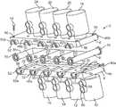
- FIG. 1illustrates an exploded, perspective view of an encapsulated valve system.
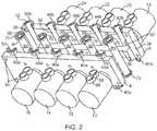
- FIG. 2illustrates another exploded, perspective view of an encapsulated valve system.
- FIG. 3illustrates a perspective view of the first housing portion of the encapsulated valve system along with a cross-sectional, perspective view of the disposable conduit.
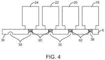
- FIG. 4illustrates a side cross-sectional view of the second housing portion of the encapsulated valve system illustrating the pinch valve actuators.
- FIG. 5illustrates an exploded, perspective view of an encapsulated valve system according to another embodiment.
- FIG. 6illustrates a perspective view of the first housing portion of the encapsulated valve system of FIG. 5 along with a cross-sectional, perspective view of the disposable conduit.
- FIG. 7illustrates a perspective view of the second housing portion of the encapsulated valve system of FIG. 5 along with a cross-sectional, perspective view of the disposable conduit.
- FIG. 8illustrates an exploded, perspective view of an encapsulated valve system according to another embodiment.
- FIG. 9illustrates an exploded, perspective view of an encapsulated valve system according to another embodiment.
- FIG. 10illustrates a perspective view of the underside of a first housing portion of the encapsulated valve system of FIG. 9 .
- FIG. 11illustrates a perspective view of the underside of a second housing portion of the encapsulated valve system of FIG. 9 .
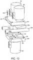
- FIG. 12illustrates an exploded, perspective view of an encapsulated valve system according to another embodiment.
- FIGS. 1-3illustrate an encapsulated valve system 2 according to one embodiment.
- the encapsulated valve system 2includes a first housing portion 4 , a second housing portion 6 , and a disposable conduit 8 that, in an assembled state, is interposed between the first housing portion 4 and the second housing portion 6 .
- the encapsulated valve system 2further includes a plurality of pinch valve actuators 10 , 12 , 14 , 16 , 18 , 20 , 22 , 24 .
- pinch valve actuators 10 , 12 , 14 , and 16are mounted on the first housing portion 4 while pinch valve actuators 18 , 20 , 22 , and 24 are mounted on the second housing portion 6 .
- eight (8) pinch valve actuatorsare illustrated in FIGS. 1-2 (four (4) are illustrated in FIG. 3 ) more or less may be included depending on the particular configuration of the encapsulated valve system 2 .
- the first housing portion 4has a first facing surface 30 that includes a plurality of branch passageways 32 formed as a recess within the first facing surface 30 of the first housing portion 4 .
- the recesses that form the plurality of branch passageways 32may be milled, worked, or molded into the first facing surface 30 .
- the first housing portion 4 and the second housing portion 6may be formed from a metallic material such as, for instance, stainless steel.
- the first housing portion 4 and the second housing portion 6may be formed from a polymer material such as plastic or the like. In a similar manner, as best seen in FIG.
- the second housing portion 6has a second facing surface 36 and includes a plurality of branch passageways 38 formed as a recess within the second facing surface 36 of the second housing portion 6 .
- the recesses formed in the second facing surface 36may be formed is the same manner with respect to those recesses within the first facing surface 30 .
- the branch passageways 32 , 38are formed the first and second facing surfaces 30 , 36 , respectively, in a mirrored fashion such that the corresponding recesses match to form a substantially concentric passageway (combined recesses 32 , 28 ) when the first facing surface 30 is brought into contact (or close proximity) with the second facing surface 36 .
- the plurality of branch passageways 32 , 38terminate at respective flange fittings 40 a , 40 b , 42 a , 42 b , 44 a , 44 b , 46 a , 46 b , 48 a , 48 b , 50 a , 50 b .
- Each flange fittingrepresents one-half of the complete flange fitting.
- the complete flange fitting(e.g., 40 a and 40 b ) appear circular in shape although other geometries may be utilized.
- the flange fittings 40 a , 40 b , 42 a , 42 b , 44 a , 44 b , 46 a , 46 b , 48 a , 48 b , 50 a , 50 bmay be formed to conform to uniform standards within the relevant industry or application. For example, there are universal shapes and sizes that are typically employed in various applications.
- each flange fitting 40 a , 40 b , 42 a , 42 b , 44 a , 44 b , 46 a , 46 b , 48 a , 48 b , 50 a , 50 bmay be designed to conform to these standards or commercial conventions other sizes are also contemplated to fall within the scope of the invention.
- Each flange fitting 40 a , 40 b , 42 a , 42 b , 44 a , 44 b , 46 a , 46 b , 48 a , 48 b , 50 a , 50 boptionally includes a recess 52 that is dimensioned to receive seal or gasket (explained more below).
- a seal or gasketcan be placed into the recess 52 so that a good fluidic seal can be formed between other devices and apparatus and the various complete flange fittings.
- the branch passageways 32 , 38may terminate in plain tube endings or other types of connectors known to those skilled in the art.
- the connectorsmay be integrally formed into the first and second housing portions 4 , 6 or they may be secured after formation of the first and second housing portions 4 , 6 .
- the endings or connectorsmay be welded, bonded, or otherwise affixed to the first and second housing portions 4 , 6 .
- the endings or connectorsmay be configured to adapt to other mechanical or heat-weldable union types known to those skilled in the art.
- the first and second housing portions 4 , 6may not have any flange fittings, for example, as illustrated in FIG. 8 .
- the first housing portion 4 and the second housing portion 6may be secured to one another via a fastener 54 .
- the fastener 54is a screw or bolt that passes through apertures 56 that are located in the first housing portion 4 and the second housing portion 6 .
- the fastener 54may include other devices such as clamps, bolts or the like. It may even be possible to use a water-soluble adhesive bond between the first housing portion 4 and the second housing portion 6 .
- the fasteners 54are configured to be removable such that the first housing portion 4 can be separated from the second housing portion 6 to remove the inner disposable conduit 8 .
- apertures 60that are dimensioned to receive a pinching element 62 (seen in FIG. 4 ) from respective pinch valve actuators 10 , 12 , 14 , 16 . Similar apertures 60 are located in the branch passageways 38 of the second housing portion 6 . Once such aperture 60 is seen in FIG. 2 .
- the locations of the various apertures 60are chosen to provide the ability to valve or gate a fluid medium into one or more selected branch passageways 32 , 38 .
- the locations of the apertures in the first housing portion 4may be different from those in the second housing portion 6 .
- the disposable conduit 8is pinched only on one side within the respective passageway 32 , 38 .
- the various actuators 10 , 12 , 14 , 16 , 18 , 20 , 22 , and 24operate in a so-called block and bleed arrangement.
- Certain actuatorssuch as, for instance, pinch valve actuators 10 , 12 , 14 , and 16 may act as blocking actuators that block selected areas of the common line 8 a of the disposable conduit 8 as seen in FIG. 3 .
- Still other actuatorssuch as, for instance, pinch valve actuators 18 , 20 , 22 , 24 may act as bleed actuators that pinch branch lines 8 b as seen in FIG. 3 .
- the apertures 60 in the first housing portion 4are aligned with the location of the apertures in the second housing portion 6 .
- the disposable conduit 8may be pinched by respective pinching elements 62 of opposing pinch valve actuators (e.g., pinch valve actuators 10 and 18 ).
- FIG. 4illustrates a cross-sectional view of the pinch valve actuators 18 , 20 , 22 , and 24 mounted on the second housing portion 6 .
- Each pinch valve actuator 18 , 20 , 22 , 24includes a pinching element 62 that, when actuated, moves downward within the branch passageway 38 to pinch the disposable conduit 8 (not shown in FIG. 4 for clarity).
- the pinch valve actuators 10 , 12 , 14 , 16 , 18 , 20 , 22 , 24are automatically-controlled actuators.
- the pinch valve actuators 10 , 12 , 14 , 16 , 18 , 20 , 22 , 24are pneumatically controlled pinch valve actuators.
- compressed or pressurized (or even vacuum pressure) airis used to control the actuators in an on/off state.
- the “off” statemay include when the respective pinching element 62 is retracted while the “on” state may include when the respective pinching element 62 is extended into the branch passageway 32 , 38 .
- the pinch valve actuators 10 , 12 , 14 , 16 , 18 , 20 , 22 , 24may each include an inlet 66 and an outlet 68 (illustrated on pinch valve actuator 10 ).
- the pinch valve actuators 10 , 12 , 14 , 16 , 18 , 20 , 22 , 24may include air-to-spring or air-to-air actuators.
- pinch valve actuators 10 , 12 , 14 , 16 , 18 , 20 , 22 , 24are illustrated in FIGS. 1-4 , the pinch valve actuators may be electrical in nature. These include, by way of example, various types of actuators including solenoid coil-based actuators, stepper motor-based actuators, or servo-motor-based actuators. In yet another alternative, the pinch valve actuators 10 , 12 , 14 , 16 , 18 , 20 , 22 , 24 may even be manually-controlled though the use of a knob, lever, or the like. In addition, some pinch valve actuators may be automatically controlled while others may be manually controlled.
- the disposable conduit 8may include a seal or gasket 70 located at terminal ends thereof.
- a seal or gasket 70located at terminal ends thereof.
- Six (6) such seals 70are illustrated in FIGS. 1-3 .
- the seals 70are dimensioned to fit within the recess 52 of each flange fitting 40 a , 40 b , 42 a , 42 b , 44 a , 44 b , 46 a , 46 b , 48 a , 48 b , 50 a , 50 b .
- a seal 70can be placed into the recess 52 so that a good fluidic seal can be formed between other devices and apparatus and the various complete flange fittings.
- connectors or endscan be employed other than the specifically illustrated flange fittings 40 a , 40 b , 42 a , 42 b , 44 a , 44 b , 46 a , 46 b , 48 a , 48 b , 50 a , 50 b .
- Theseinclude plain tubes or ends configured for adapting to other types of connectors such as, for instance, the BioQuate Disposable Aseptic Connector (DAC) available from BioQuate, Inc., Clearwater, Fla., or the KLEENPAK sterile connector (Pall Life Sciences Products, East Hills, N.Y.).
- DACBioQuate Disposable Aseptic Connector
- KLEENPAK sterile connectorPall Life Sciences Products, East Hills, N.Y.
- the disposable conduit 8may be made of un-reinforced silicone tubing. In this manner, there is no need to use expensive and inflexible reinforced tubing.
- the first housing portion 4 and the second housing portion 6serve to encapsulate the disposable conduit 8 in a sort of exoskeleton that prevents the formation of aneurysms within the disposable conduit 8 .
- the encapsulated structurealso enables very high pressure ratings for the encapsulated valve system 10 .
- un-reinforced silicone tubingmay be used for the disposable conduit 8
- other materials suitable for this purposeinclude by way of example C-FLEX tubing (Saint-Gobain, France) or tubing made of STA-PURE (W.L.
- the un-reinforced tubingis made from a polymeric material.
- FIGS. 5-7illustrate an alternative embodiment of an encapsulated valve system 80 .
- the encapsulated valve system 80includes a first housing portion 84 , a second housing portion 86 , and a disposable conduit 88 that, in an assembled state, is interposed between the first housing portion 84 and the second housing portion 86 .
- the encapsulated valve system 80further includes a plurality of pinch valve actuators 88 , 90 , 92 . As seen in FIG. 5 , pinch valve actuator 88 is mounted on the first housing portion 84 while pinch valve actuators 90 , 92 are mounted on the second housing portion 86 .
- the first housing portion 84 and the second housing portion 86may be secured to one another using a fastener 94 that passes through aperture 95 .
- the disposable conduit 88may be formed from the same materials described above with respect to the embodiment of FIGS. 1-4 .
- the disposable conduit 88may include a seal or gasket 89 located at terminal ends thereof.
- the seal or gasket 89may be integrally formed with the conduit 88 or, alternatively, as a separate structure.
- the disposable conduit 88may itself terminate in a seal or gasket 89 .
- first housing portion 84 and the second housing portion 86include flange fittings 96 a , 96 b , 98 a , 98 b , 100 a , 100 b , and 102 a , 102 b that combine together (as halves) to form complete fittings as described above.
- the pinch valve actuators 88 , 90 , 92are illustrated as being pneumatically operated as described above. Of course, various other types of pinch valve actuators may be employed.
- FIG. 6illustrates a cross-sectional view taken through the disposable conduit 88 that lies within the branch passageways 104 .
- the first facing surface 85 of the first housing portion 84is illustrated.
- FIG. 7illustrates the corresponding second facing surface 87 of the second housing portion 86 that is brought into contact with (or near) the first facing surface 85 when the disposable conduit 88 is interposed between two housing portions 84 , 86 .
- a first pathway 106extends across the first facing surface 85 of the first housing portion 84 and the second surface 87 of the second housing portion 86 ( FIG. 7 ).
- a second pathway 108extends across the first facing surface 85 of the first housing portion 84 and the second surface 87 of the second housing portion 86 ( FIG. 7 ).
- a third pathway 110is formed in both the first facing surface 85 and the second facing surface 87 and bridges the first pathway 106 to the second pathway 108 .
- the third pathway 110includes an aperture 112 that is dimensioned to receive a pinching element from pinch valve actuator 88 which is the same as previously described herein.
- FIG. 7illustrates the underside of the second housing portion 86 .
- two apertures 114 , 116are formed in the first pathway 106 and the second pathway 108 .
- These apertures 114 , 116are dimensioned to receive pinching elements from respective pinch valve actuators 90 , 92 which are the same as previously described herein.
- the branch pathways 106 , 108 , 110form an H-shape.
- the disposable conduit 88is shaped in the form of an H as well with two side portions 88 a , 88 b and a bridging portion 88 c .
- the pinch valve actuator 88when actuated, blocks flow between the first and second pathways 106 , 108 .
- the remaining pinch valve actuators 90 , 92prevent fluid from passing into or exiting from pathways 106 , 108 .
- this embodiment of the encapsulated valve system 80may operate in a so-called block and bleed arrangement.
- FIG. 8illustrates an alternative embodiment of an encapsulated valve system 120 .
- the encapsulated valve system 120includes a first housing portion 122 , a second housing portion 124 , and a disposable conduit 126 that, in an assembled state, is interposed between the first housing portion 122 and the second housing portion 124 .
- the encapsulated valve system 120further includes a plurality of pinch valve actuators 128 , 130 , 132 .
- a pinch valve actuator 128is mounted on the first housing portion 122 while pinch valve actuators 130 , 132 are mounted on the second housing portion 124 .
- the various pinch valve actuators 128 , 130 , 132operate in a similar manner as described herein.
- a plurality of branch pathwaysincludes first pathway 138 , second pathway 140 , and bridging pathway 142 .
- the first housing portion 122 and the second housing portion 124may be secured to one another using a fastener 134 that passes through aperture 136 .
- a fastener 134that passes through aperture 136 .
- the disposable conduit 126may be formed from the same materials described above with respect to the embodiment of FIGS. 1-7 .
- the first housing portion 122 and the second housing portion 124do not include any flange fittings. Rather, the first and second pathways 138 and 140 terminate simply at an opening (or exit as the case may be) in the respective halves of the first housing portion 122 and the second housing portion 124 . In the embodiment of FIG.
- the terminal ends 144 of the disposable conduitmay optionally be constructed to include fittings 146 that are designed to interface or connect with other components.
- the particular fitting 146may include a sealing member, gasket, or the like that can then be used to create a fluidic seal with another device or component.
- the particular fitting 146may vary according to the particular application in which the encapsulated valve system 120 is used.
- FIGS. 9-11illustrate an encapsulated valve system 150 according to another embodiment.
- the encapsulated valve system 150includes a first housing portion 152 , a second housing portion 154 , and a disposable conduit 156 that, in an assembled state, is interposed between the first housing portion 152 and the second housing portion 154 .
- the encapsulated valve system 150further includes a plurality of pinch valve actuators 160 , 162 , 164 , 166 , 168 , 170 , 172 , 174 . As seen in FIGS. 9-11 , pinch valve actuators 160 , 162 , 164 , 166 are mounted on the second housing portion 154 while pinch valve actuator 168 is mounted on the first housing portion 152 .
- pinch valve actuators 170 , 172 , 174are mounted along the interface or seam 176 created between the first housing portion 152 and the second housing portion 154 . These pinch valve actuators 170 , 172 , 174 are generally oriented perpendicular or orthogonal to the pinch valve actuators 160 , 162 , 164 , 166 , 168 . While eight (8) pinch valve actuators are illustrated in FIGS. 9-11 more or less may be included depending on the particular configuration of the encapsulated valve system 150 .
- the first housing portion 152has a first facing surface 178 that includes a plurality of branch passageways 180 formed as a recess within the first facing surface 178 of the first housing portion 152 .
- the recesses that form the plurality of branch passageways 180may be milled, worked, or molded into the first facing surface 178 as previously described herein.
- the second housing portion 154has a second facing surface 182 and includes a plurality of branch passageways 184 formed as a recess within the second facing surface 182 of the second housing portion 154 .
- the recesses formed in the second facing surface 182may be formed is the same manner with respect to those recesses within the first facing surface 178 .
- the branch passageways 180 , 184are formed the first and second facing surfaces 178 , 182 , respectively, in a mirrored fashion such that the corresponding recesses match to form a substantially concentric passageway when the first facing surface 178 is brought into contact (or close proximity) with the second facing surface 182 .
- the plurality of branch passageways 180 , 184terminate at respective flange fittings 186 a , 186 b , 188 a , 188 b , 190 a , 190 b , 192 a , 192 b , 194 a , 194 b , 196 a , 196 b .
- Each flange fittingrepresents one-half of the complete flange fitting.
- the complete flange fitting(e.g., 186 a and 186 b ) appear circular in shape although other geometries may be utilized.
- the flange fittings 186 a , 186 b , 188 a , 188 b , 190 a , 190 b , 192 a , 192 b , 194 a , 194 b , 196 a , 196 bmay be formed to conform to uniform standards within the relevant industry or application.
- flange fittings 186 a , 186 b , 188 a , 188 b , 190 a , 190 b , 192 a , 192 b , 194 a , 194 b , 196 a , 196 bmay be designed to conform to these standards or commercial conventions other sizes are also contemplated to fall within the scope of the invention.
- Each flange fitting 186 a , 186 b , 188 a , 188 b , 190 a , 190 b , 192 a , 192 b , 194 a , 194 b , 196 a , 196 boptionally includes a recess 198 ( FIG. 9 ) that is dimensioned to receive seal or gasket similar to that discussed herein with respect to the embodiment of FIGS. 1-3 .
- the branch passageways 180 , 184may terminate in plain tube endings or other types of connectors known to those skilled in the art.
- the connectorsmay be integrally formed into the first and second housing portions 152 , 154 or they may be secured after formation of the first and second housing portions 152 , 154 .
- the endings or connectorsmay be welded, bonded, or otherwise affixed to the first and second housing portions 152 , 154 .
- the endings or connectorsmay be configured to adapt to other mechanical or heat-weldable union types known to those skilled in the art.
- the first and second housing portions 152 , 154may not have any flange fittings, for example, as illustrated in FIG. 8 .
- the first housing portion 152 and the second housing portion 154may be secured to one another via a fastener 200 .
- the fastener 200is a screw or bolt that passes through apertures 202 that are located in the first housing portion 152 and the second housing portion 154 .
- the fastener 200may include other devices such as clamps, bolts or the like. It may even be possible to use an adhesive bond between the first housing portion 152 and the second housing portion 154 .
- the fasteners 200are configured to be removable such that the first housing portion 152 can be separated from the second housing portion 154 to remove the inner disposable conduit 156 .
- apertures 206that are dimensioned to receive a pinching element 208 (seen in FIG. 10 ) from respective pinch valve actuators 160 , 162 , 164 , 166 , 168 , 170 , 172 , 174 .
- the various apertures 206are associated with a respective actuator as described herein.
- the locations of the various apertures 206are chosen to provide the ability to valve or gate a fluid medium into one or more selected branch passageways 180 , 184 as previously described.
- An advantage of having the pinch valve actuators 170 , 172 , 174 located along the seam or interface 176 formed between the first housing portion 152 and the second housing portion 154is that this reduces the overall size or footprint of the encapsulated valve system 150 . This is particularly important given that multiple encapsulated valve systems 150 may be used in a particular process or operation. For example, as one alternative aspect, the actuator 168 may even be moved to a lateral position along the seam 176 . This would reduce the overall height of the encapsulated valve system.
- Another advantage of the embodiment of FIGS. 9-11is that the amount of residual volume of fluid contained in the encapsulated valve system 150 can be reduced.
- FIG. 12illustrates an embodiment similar to that illustrated in FIG. 5 with the exception that the second housing portion 86 does not include flange fittings 96 a , 96 b , 98 a , 98 b , 100 a , 100 b , and 102 a , 102 b .
- the embodiment illustrated in FIG. 12also does not include a seal or gasket 89 located at the terminal ends of the disposable conduit 88 . Instead, the terminal ends of the disposable conduit 88 merely terminates at a cut end that then can be mating with any number of configurations whether hygienic or non-hygienic known to those skilled in the art.
- FIG. 12illustrates the pinch valve actuators 88 , 90 , 92 on opposing sides of the first and second housing portions 84 , 86 , it should be understood that the pinch valve actuators 88 , 90 , 92 may be located along a seam like that illustrated in FIGS. 9-11 . The same applies to the embodiment of FIG. 5 . While embodiments of the present invention have been shown and described, various modifications may be made without departing from the scope of the present invention. The invention, therefore, should not be limited, except to the following claims, and their equivalents.
Landscapes
- Engineering & Computer Science (AREA)
- General Engineering & Computer Science (AREA)
- Mechanical Engineering (AREA)
- Physics & Mathematics (AREA)
- Fluid Mechanics (AREA)
- Chemical & Material Sciences (AREA)
- Organic Chemistry (AREA)
- Chemical Kinetics & Catalysis (AREA)
- Valve Housings (AREA)
- External Artificial Organs (AREA)
- Multiple-Way Valves (AREA)
Abstract
Description
Claims (13)
Priority Applications (4)
| Application Number | Priority Date | Filing Date | Title |
|---|---|---|---|
| US16/267,997US11022223B2 (en) | 2009-05-15 | 2019-02-05 | Encapsulated valve system and method of use |
| US17/306,513US12181076B2 (en) | 2009-05-15 | 2021-05-03 | Encapsulated valve system and method of use |
| US17/690,169US12253189B2 (en) | 2009-05-15 | 2022-03-09 | Encapsulated valve system and method of use |
| US17/869,009US11719348B2 (en) | 2009-05-15 | 2022-07-20 | Encapsulated valve system and method of use |
Applications Claiming Priority (5)
| Application Number | Priority Date | Filing Date | Title |
|---|---|---|---|
| US12/466,918US8235067B2 (en) | 2009-05-15 | 2009-05-15 | Encapsulated valve system |
| US13/554,983US8656951B2 (en) | 2009-05-15 | 2012-07-20 | Encapsulated valve system |
| US14/165,206US9447888B2 (en) | 2009-05-15 | 2014-01-27 | Encapsulated valve system |
| US15/252,134US10234044B2 (en) | 2009-05-15 | 2016-08-30 | Encapsulated valve system and method of use |
| US16/267,997US11022223B2 (en) | 2009-05-15 | 2019-02-05 | Encapsulated valve system and method of use |
Related Parent Applications (1)
| Application Number | Title | Priority Date | Filing Date |
|---|---|---|---|
| US15/252,134ContinuationUS10234044B2 (en) | 2009-05-15 | 2016-08-30 | Encapsulated valve system and method of use |
Related Child Applications (1)
| Application Number | Title | Priority Date | Filing Date |
|---|---|---|---|
| US17/306,513ContinuationUS12181076B2 (en) | 2009-05-15 | 2021-05-03 | Encapsulated valve system and method of use |
Publications (2)
| Publication Number | Publication Date |
|---|---|
| US20190178393A1 US20190178393A1 (en) | 2019-06-13 |
| US11022223B2true US11022223B2 (en) | 2021-06-01 |
Family
ID=43067547
Family Applications (8)
| Application Number | Title | Priority Date | Filing Date |
|---|---|---|---|
| US12/466,918Expired - Fee RelatedUS8235067B2 (en) | 2009-05-15 | 2009-05-15 | Encapsulated valve system |
| US13/554,983ActiveUS8656951B2 (en) | 2009-05-15 | 2012-07-20 | Encapsulated valve system |
| US14/165,206ActiveUS9447888B2 (en) | 2009-05-15 | 2014-01-27 | Encapsulated valve system |
| US15/252,134ActiveUS10234044B2 (en) | 2009-05-15 | 2016-08-30 | Encapsulated valve system and method of use |
| US16/267,997Expired - Fee RelatedUS11022223B2 (en) | 2009-05-15 | 2019-02-05 | Encapsulated valve system and method of use |
| US17/306,513Active2030-02-16US12181076B2 (en) | 2009-05-15 | 2021-05-03 | Encapsulated valve system and method of use |
| US17/690,169ActiveUS12253189B2 (en) | 2009-05-15 | 2022-03-09 | Encapsulated valve system and method of use |
| US17/869,009ActiveUS11719348B2 (en) | 2009-05-15 | 2022-07-20 | Encapsulated valve system and method of use |
Family Applications Before (4)
| Application Number | Title | Priority Date | Filing Date |
|---|---|---|---|
| US12/466,918Expired - Fee RelatedUS8235067B2 (en) | 2009-05-15 | 2009-05-15 | Encapsulated valve system |
| US13/554,983ActiveUS8656951B2 (en) | 2009-05-15 | 2012-07-20 | Encapsulated valve system |
| US14/165,206ActiveUS9447888B2 (en) | 2009-05-15 | 2014-01-27 | Encapsulated valve system |
| US15/252,134ActiveUS10234044B2 (en) | 2009-05-15 | 2016-08-30 | Encapsulated valve system and method of use |
Family Applications After (3)
| Application Number | Title | Priority Date | Filing Date |
|---|---|---|---|
| US17/306,513Active2030-02-16US12181076B2 (en) | 2009-05-15 | 2021-05-03 | Encapsulated valve system and method of use |
| US17/690,169ActiveUS12253189B2 (en) | 2009-05-15 | 2022-03-09 | Encapsulated valve system and method of use |
| US17/869,009ActiveUS11719348B2 (en) | 2009-05-15 | 2022-07-20 | Encapsulated valve system and method of use |
Country Status (6)
| Country | Link |
|---|---|
| US (8) | US8235067B2 (en) |
| EP (1) | EP2432583B1 (en) |
| KR (3) | KR101874275B1 (en) |
| ES (1) | ES2678120T3 (en) |
| SG (1) | SG175918A1 (en) |
| WO (1) | WO2010132435A1 (en) |
Families Citing this family (32)
| Publication number | Priority date | Publication date | Assignee | Title |
|---|---|---|---|---|
| US8235067B2 (en) | 2009-05-15 | 2012-08-07 | Alphabio, Inc. | Encapsulated valve system |
| US9376305B2 (en) | 2011-06-22 | 2016-06-28 | Allpure Technologies, Inc. | Fluid transfer interface |
| EP3357830B1 (en) | 2011-06-22 | 2019-07-24 | Sartorius Stedim North America Inc. | Vessel closure and method for manufacturing the same |
| US10773863B2 (en) | 2011-06-22 | 2020-09-15 | Sartorius Stedim North America Inc. | Vessel closures and methods for using and manufacturing same |
| DE102011111055B4 (en)* | 2011-08-24 | 2014-06-18 | Viega Gmbh & Co. Kg | System of a fastening device and a fitting |
| EP3077324A4 (en) | 2013-12-06 | 2017-08-02 | Allpure Technologies, Inc. | Fluid transfer interface |
| KR102442538B1 (en)* | 2014-01-17 | 2022-09-08 | 알피니티, 엘엘씨 | Fluid monitoring assembly with sensor functionality |
| JP6776242B2 (en) | 2014-12-19 | 2020-10-28 | アルフィニティ, エルエルシーAlphinity, Llc | Encapsulation system for pressurized fluid processes |
| US10309818B2 (en) | 2015-05-19 | 2019-06-04 | Alphinity, Llc | Fluid monitoring assembly with flow sensor |
| KR102653403B1 (en)* | 2015-09-15 | 2024-04-02 | 리플리겐 코포레이션 | Flexible piping management systems for pharmaceutical, bioprocess applications, and food/dairy applications |
| KR20240122594A (en) | 2015-10-01 | 2024-08-12 | 리플리겐 코포레이션 | Valve assembly with directional flow path |
| MX386626B (en)* | 2016-01-27 | 2025-03-19 | Alcantara Talavera Magno | FLOW REGULATOR IN LIQUID DISTRIBUTION SYSTEM WITH THERMOREGULATORY ELEMENT. |
| EP3419741A2 (en)* | 2016-02-26 | 2019-01-02 | GE Healthcare Bio-Sciences AB | Method for pressure control in crossflow filtration using high precision pinch valves |
| DE102016107161A1 (en)* | 2016-04-18 | 2017-10-19 | Eto Magnetic Gmbh | Pneumatic multi-valve device and manufacturing method |
| KR102547782B1 (en) | 2017-01-31 | 2023-06-23 | 알피니티 유에스에이, 인크. | Bioprocess vessel with integral pump |
| BE1024953B1 (en)* | 2017-01-31 | 2018-08-30 | Out And Out Chemistry Sprl | Method for connecting at least two fluidic valves and the fluidic communication system implemented |
| KR102230283B1 (en)* | 2017-02-20 | 2021-03-19 | 가부시키가이샤 후지킨 | Fluid controller abnormality detection device, abnormality detection system, abnormality detection method and fluid controller unit |
| US10578220B2 (en) | 2017-02-27 | 2020-03-03 | Bimba Manufacturing Company | Proportionally controlled pinch valves, systems and methods |
| KR102327250B1 (en)* | 2017-10-13 | 2021-11-17 | 생-고뱅 퍼포먼스 플라스틱스 코포레이션 | Fluid manifolds and methods of making them |
| US12252391B2 (en) | 2017-11-14 | 2025-03-18 | Sartorius Stedim North America Inc. | System for simultaneous distribution of fluid to multiple vessels and method of using the same |
| US11577953B2 (en) | 2017-11-14 | 2023-02-14 | Sartorius Stedim North America, Inc. | System for simultaneous distribution of fluid to multiple vessels and method of using the same |
| US11691866B2 (en) | 2017-11-14 | 2023-07-04 | Sartorius Stedim North America Inc. | System for simultaneous distribution of fluid to multiple vessels and method of using the same |
| US11319201B2 (en) | 2019-07-23 | 2022-05-03 | Sartorius Stedim North America Inc. | System for simultaneous filling of multiple containers |
| CA3109664A1 (en)* | 2018-08-13 | 2020-02-20 | Invetech, Inc. | Functionalized unitary molded manifolds for closed fluid handling systems |
| US20240033179A1 (en)* | 2020-09-22 | 2024-02-01 | Alphinity Usa, Inc. | Systems and methods for the preparation of fluids for bioprocess and pharmaceutical applications |
| GB202105923D0 (en) | 2021-04-26 | 2021-06-09 | Cytiva Sweden Ab | Reconfigurable bioprocessing systems |
| US20220390967A1 (en)* | 2021-06-02 | 2022-12-08 | Caterpillar Inc. | Pumping system and method for providing constant fluid flow |
| US12239127B2 (en) | 2021-07-28 | 2025-03-04 | Sartorius Stedim North America Inc. | Thermal capacitors, systems, and methods for rapid freezing or heating of biological materials |
| CN114001181B (en)* | 2022-01-04 | 2022-04-08 | 浙江金仪盛世生物工程有限公司 | Pinch valve head and pinch valve group with same |
| CN114001180B (en)* | 2022-01-04 | 2022-04-08 | 浙江金仪盛世生物工程有限公司 | Pinch valve head for switching and pinch valve group |
| CN114576387B (en)* | 2022-02-17 | 2024-08-13 | 马俊 | Fluid hose clamp pipe valve |
| US12152699B2 (en)* | 2022-02-28 | 2024-11-26 | Terumo Bct, Inc. | Multiple-tube pinch valve assembly |
Citations (26)
| Publication number | Priority date | Publication date | Assignee | Title |
|---|---|---|---|---|
| US2931387A (en) | 1957-08-22 | 1960-04-05 | Robertson Co H H | Control apparatus for domestic water distribution system |
| GB1055426A (en) | 1963-11-22 | 1967-01-18 | Kelsto Engineering Company Ltd | Improvements in or relating to pinch valves |
| US4254797A (en)* | 1979-01-26 | 1981-03-10 | Bi-M Instrument Company | Apparatus for producing calibration gases suitable for analytical instrumentation |
| US4895341A (en) | 1988-09-30 | 1990-01-23 | Whitey Co. | Pinch valve |
| US5005604A (en)* | 1984-07-13 | 1991-04-09 | Aslanian Jerry L | Flow control device for administration of intravenous fluids |
| US5197708A (en) | 1992-08-11 | 1993-03-30 | Flow-Rite Controls, Ltd. | Tubing pinch valve device |
| US5350290A (en) | 1993-01-19 | 1994-09-27 | Amf Machinery Systems, Inc. | Manifold and valving arrangement for dough divider |
| US5549134A (en) | 1994-05-27 | 1996-08-27 | Marcvalve Corporation | Diaphragm valve |
| US6036166A (en) | 1997-09-25 | 2000-03-14 | Imi Cornelius Inc. | Chamber valve |
| US6068751A (en) | 1995-12-18 | 2000-05-30 | Neukermans; Armand P. | Microfluidic valve and integrated microfluidic system |
| US20030010946A1 (en) | 2000-12-05 | 2003-01-16 | Shigenobu Furukawa | Pinch valve |
| US6543483B2 (en) | 1998-10-23 | 2003-04-08 | Chemand Corporation | Fluid handling port array |
| US6554589B2 (en) | 1997-07-03 | 2003-04-29 | Precision Dispensing Systems Limited | Flexible tube pinch mechanism |
| US6631736B2 (en) | 2000-07-22 | 2003-10-14 | Ballard Power Systems Ag | Device for metering a gaseous medium |
| US6644353B1 (en) | 1998-03-05 | 2003-11-11 | Swagelok Company | Modular surface mount manifold |
| US20040163711A1 (en) | 2003-02-20 | 2004-08-26 | Graham Packaging Company, L.P. | Fluid regulating pinch valve |
| JP2004293769A (en) | 2003-03-28 | 2004-10-21 | Japan Aviation Electronics Industry Ltd | Flow controller |
| US6976664B2 (en) | 2003-08-11 | 2005-12-20 | Mitos Technologies, Inc. | Free flow valve and element |
| US20060048818A1 (en)* | 2004-09-07 | 2006-03-09 | Welch Steven D | Multi-port free flow valve and element |
| US7104275B2 (en) | 2002-04-01 | 2006-09-12 | Emerson Electric Co. | Pinch valve |
| US20070278155A1 (en) | 2004-11-04 | 2007-12-06 | Baxter International Inc. | Medical fluid system with flexible sheeting disposable unit |
| US20070295867A1 (en) | 2006-06-21 | 2007-12-27 | Hennon John | Conduit support apparatus |
| US20080035227A1 (en) | 2005-07-14 | 2008-02-14 | Pdc Facilities, Inc. | Liner for a flow meter |
| US7367363B2 (en) | 2003-06-18 | 2008-05-06 | Pbm, Inc. | Sanitary conduit support systems |
| US20080237509A1 (en) | 2007-03-30 | 2008-10-02 | Asahi Organic Chemicals Industry Co., Ltd. | Piping Member |
| US20090120503A1 (en) | 2006-07-21 | 2009-05-14 | Amgen Inc. | Valve for controlling the flow of steam and other fluids |
Family Cites Families (12)
| Publication number | Priority date | Publication date | Assignee | Title |
|---|---|---|---|---|
| US2674435A (en)* | 1950-03-30 | 1954-04-06 | White S Dental Mfg Co | Tube compressor |
| US3559683A (en)* | 1969-06-12 | 1971-02-02 | Samsonite Corp | Fluid control device |
| US3823724A (en) | 1973-05-25 | 1974-07-16 | Med Lab Computer Services Inc | Controlling flow of medical fluids |
| US4496133A (en) | 1982-03-02 | 1985-01-29 | Akos Sule | Pinch valve assembly |
| US4512764A (en)* | 1982-09-27 | 1985-04-23 | Wunsch Richard E | Manifold for controlling administration of multiple intravenous solutions and medications |
| US4559036A (en)* | 1983-12-14 | 1985-12-17 | Wunsch Richard E | Apparatus for controlling administration of multiple intravenous solutions and medications |
| US4524802A (en)* | 1984-10-01 | 1985-06-25 | Bio-Chem Valve Corp. | Pinch valve |
| US4607659A (en)* | 1985-08-12 | 1986-08-26 | Cole George S | Valve with resilient tubes having constricted portions |
| DE10114330B4 (en) | 2001-03-23 | 2005-03-10 | Ferton Holding Sa | Valve arrangement in a midizinischen device |
| US20060237066A1 (en) | 2005-04-25 | 2006-10-26 | Gagne Michael C | Versatile valve |
| US8235067B2 (en) | 2009-05-15 | 2012-08-07 | Alphabio, Inc. | Encapsulated valve system |
| US11674617B2 (en)* | 2019-12-27 | 2023-06-13 | Horizon Healthcare LLC | Tube lock |
- 2009
- 2009-05-15USUS12/466,918patent/US8235067B2/ennot_activeExpired - Fee Related
- 2010
- 2010-05-11SGSG2011081742Apatent/SG175918A1/enunknown
- 2010-05-11ESES10775392.3Tpatent/ES2678120T3/enactiveActive
- 2010-05-11KRKR1020177027166Apatent/KR101874275B1/ennot_activeExpired - Fee Related
- 2010-05-11KRKR20117027072Apatent/KR20120049179A/ennot_activeWithdrawn
- 2010-05-11KRKR1020187018130Apatent/KR101925889B1/ennot_activeExpired - Fee Related
- 2010-05-11WOPCT/US2010/034371patent/WO2010132435A1/enactiveApplication Filing
- 2010-05-11EPEP10775392.3Apatent/EP2432583B1/enactiveActive
- 2012
- 2012-07-20USUS13/554,983patent/US8656951B2/enactiveActive
- 2014
- 2014-01-27USUS14/165,206patent/US9447888B2/enactiveActive
- 2016
- 2016-08-30USUS15/252,134patent/US10234044B2/enactiveActive
- 2019
- 2019-02-05USUS16/267,997patent/US11022223B2/ennot_activeExpired - Fee Related
- 2021
- 2021-05-03USUS17/306,513patent/US12181076B2/enactiveActive
- 2022
- 2022-03-09USUS17/690,169patent/US12253189B2/enactiveActive
- 2022-07-20USUS17/869,009patent/US11719348B2/enactiveActive
Patent Citations (27)
| Publication number | Priority date | Publication date | Assignee | Title |
|---|---|---|---|---|
| US2931387A (en) | 1957-08-22 | 1960-04-05 | Robertson Co H H | Control apparatus for domestic water distribution system |
| GB1055426A (en) | 1963-11-22 | 1967-01-18 | Kelsto Engineering Company Ltd | Improvements in or relating to pinch valves |
| US4254797A (en)* | 1979-01-26 | 1981-03-10 | Bi-M Instrument Company | Apparatus for producing calibration gases suitable for analytical instrumentation |
| US5005604A (en)* | 1984-07-13 | 1991-04-09 | Aslanian Jerry L | Flow control device for administration of intravenous fluids |
| US4895341A (en) | 1988-09-30 | 1990-01-23 | Whitey Co. | Pinch valve |
| US5197708A (en) | 1992-08-11 | 1993-03-30 | Flow-Rite Controls, Ltd. | Tubing pinch valve device |
| US5350290A (en) | 1993-01-19 | 1994-09-27 | Amf Machinery Systems, Inc. | Manifold and valving arrangement for dough divider |
| US5549134A (en) | 1994-05-27 | 1996-08-27 | Marcvalve Corporation | Diaphragm valve |
| US6068751A (en) | 1995-12-18 | 2000-05-30 | Neukermans; Armand P. | Microfluidic valve and integrated microfluidic system |
| US6554589B2 (en) | 1997-07-03 | 2003-04-29 | Precision Dispensing Systems Limited | Flexible tube pinch mechanism |
| US6036166A (en) | 1997-09-25 | 2000-03-14 | Imi Cornelius Inc. | Chamber valve |
| US6644353B1 (en) | 1998-03-05 | 2003-11-11 | Swagelok Company | Modular surface mount manifold |
| US6543483B2 (en) | 1998-10-23 | 2003-04-08 | Chemand Corporation | Fluid handling port array |
| US6631736B2 (en) | 2000-07-22 | 2003-10-14 | Ballard Power Systems Ag | Device for metering a gaseous medium |
| US20030010946A1 (en) | 2000-12-05 | 2003-01-16 | Shigenobu Furukawa | Pinch valve |
| US7104275B2 (en) | 2002-04-01 | 2006-09-12 | Emerson Electric Co. | Pinch valve |
| US20040163711A1 (en) | 2003-02-20 | 2004-08-26 | Graham Packaging Company, L.P. | Fluid regulating pinch valve |
| JP2004293769A (en) | 2003-03-28 | 2004-10-21 | Japan Aviation Electronics Industry Ltd | Flow controller |
| US7367363B2 (en) | 2003-06-18 | 2008-05-06 | Pbm, Inc. | Sanitary conduit support systems |
| US6976664B2 (en) | 2003-08-11 | 2005-12-20 | Mitos Technologies, Inc. | Free flow valve and element |
| US20060048818A1 (en)* | 2004-09-07 | 2006-03-09 | Welch Steven D | Multi-port free flow valve and element |
| US7383853B2 (en) | 2004-09-07 | 2008-06-10 | Parker-Hannifin Corp. | Multi-port free flow valve and element |
| US20070278155A1 (en) | 2004-11-04 | 2007-12-06 | Baxter International Inc. | Medical fluid system with flexible sheeting disposable unit |
| US20080035227A1 (en) | 2005-07-14 | 2008-02-14 | Pdc Facilities, Inc. | Liner for a flow meter |
| US20070295867A1 (en) | 2006-06-21 | 2007-12-27 | Hennon John | Conduit support apparatus |
| US20090120503A1 (en) | 2006-07-21 | 2009-05-14 | Amgen Inc. | Valve for controlling the flow of steam and other fluids |
| US20080237509A1 (en) | 2007-03-30 | 2008-10-02 | Asahi Organic Chemicals Industry Co., Ltd. | Piping Member |
Non-Patent Citations (10)
| Title |
|---|
| BioWorks LLC Catalog, Model: BSV-H250-Bo, www.BioWorksLLC.com, cited in U.S. Appl. No. 14/165,206 dated Aug. 25, 2014 (6pages). |
| BioWorks LLC http://bioworksllc.com/pdf/BTV_Manifold_Brochure_rev1.pdf, Pub. Date May 19, 2019 (Wayback Machine). |
| BioWorks! LLC BTV Manifold Brochure, Date May 12, 2006, http://bioworksllc.com/pdf/. |
| Communication dated Nov. 6, 2017 in European Patent Application No. 10 775 392.3-1751, (7pages). |
| Notice of Preliminary Rejection dated Dec. 14, 2016 in Korean Patent Application No. 10-2011-7027072, (11pages). |
| Parker Mitos Product Brochure, Mitos Free Flow Valve, Apr. 29, 2009, http://www.mitostech.com/freelow.html (2 pages). |
| PCT International Preliminary Report on Patentability (Chapter I of the Patent Cooperation Treaty) for PCT/US2010/034371, Applicant: AlphaBio, Inc., Form PCT/IB/326 and 373, dated Nov. 15, 2011 (9 pages). |
| PCT International Search Report for PCT/US10/34371, Applicant: AlphaBio, Inc., Form PCT/ISA/210 and 220, dated Jul. 1, 2010 (4 pages). |
| PCT Written Opinion of the International Search Authority for PCT/US10/34371, Applicant: AlphaBio, Inc., Form PCT/ISA/237, dated Jul. 1, 2010 (7 pages). |
| The extended European search report dated Nov. 29, 2016 in European Application No. 10775392.3-1751, Applicant: Alphinity, LLC, (10pages). |
Also Published As
| Publication number | Publication date |
|---|---|
| US20120279594A1 (en) | 2012-11-08 |
| US8656951B2 (en) | 2014-02-25 |
| EP2432583A4 (en) | 2016-12-28 |
| KR20170116176A (en) | 2017-10-18 |
| US9447888B2 (en) | 2016-09-20 |
| US11719348B2 (en) | 2023-08-08 |
| US20100288385A1 (en) | 2010-11-18 |
| US12181076B2 (en) | 2024-12-31 |
| US20190178393A1 (en) | 2019-06-13 |
| KR20120049179A (en) | 2012-05-16 |
| US20210254729A1 (en) | 2021-08-19 |
| US10234044B2 (en) | 2019-03-19 |
| WO2010132435A1 (en) | 2010-11-18 |
| US20220196162A1 (en) | 2022-06-23 |
| ES2678120T3 (en) | 2018-08-09 |
| US20160369902A1 (en) | 2016-12-22 |
| EP2432583A1 (en) | 2012-03-28 |
| KR101925889B1 (en) | 2018-12-07 |
| KR101874275B1 (en) | 2018-07-03 |
| US12253189B2 (en) | 2025-03-18 |
| US20140138563A1 (en) | 2014-05-22 |
| US20220356954A1 (en) | 2022-11-10 |
| US8235067B2 (en) | 2012-08-07 |
| EP2432583B1 (en) | 2018-04-18 |
| SG175918A1 (en) | 2011-12-29 |
| KR20180074817A (en) | 2018-07-03 |
Similar Documents
| Publication | Publication Date | Title |
|---|---|---|
| US11022223B2 (en) | Encapsulated valve system and method of use | |
| US11898645B2 (en) | Valve assembly with directional flow path | |
| US11530772B2 (en) | Fluid plug for sterile processes and methods of using the same | |
| US20240328523A1 (en) | Interchangeable multiport pinch valve assembly |
Legal Events
| Date | Code | Title | Description |
|---|---|---|---|
| FEPP | Fee payment procedure | Free format text:ENTITY STATUS SET TO UNDISCOUNTED (ORIGINAL EVENT CODE: BIG.); ENTITY STATUS OF PATENT OWNER: LARGE ENTITY | |
| FEPP | Fee payment procedure | Free format text:ENTITY STATUS SET TO SMALL (ORIGINAL EVENT CODE: SMAL); ENTITY STATUS OF PATENT OWNER: LARGE ENTITY | |
| STPP | Information on status: patent application and granting procedure in general | Free format text:DOCKETED NEW CASE - READY FOR EXAMINATION | |
| STPP | Information on status: patent application and granting procedure in general | Free format text:NON FINAL ACTION MAILED | |
| FEPP | Fee payment procedure | Free format text:ENTITY STATUS SET TO UNDISCOUNTED (ORIGINAL EVENT CODE: BIG.); ENTITY STATUS OF PATENT OWNER: LARGE ENTITY | |
| AS | Assignment | Owner name:ALPHINITY, LLC, NEVADA Free format text:CONFIRMATORY ASSIGNMENT;ASSIGNOR:ALPHA BIO, INC.;REEL/FRAME:054203/0152 Effective date:20201023 | |
| STPP | Information on status: patent application and granting procedure in general | Free format text:RESPONSE TO NON-FINAL OFFICE ACTION ENTERED AND FORWARDED TO EXAMINER | |
| AS | Assignment | Owner name:REPLIGEN CORPORATION, MASSACHUSETTS Free format text:ASSIGNMENT OF ASSIGNORS INTEREST;ASSIGNOR:ALPHINITY, LLC;REEL/FRAME:054580/0754 Effective date:20201203 | |
| STPP | Information on status: patent application and granting procedure in general | Free format text:NOTICE OF ALLOWANCE MAILED -- APPLICATION RECEIVED IN OFFICE OF PUBLICATIONS | |
| FEPP | Fee payment procedure | Free format text:PETITION RELATED TO MAINTENANCE FEES GRANTED (ORIGINAL EVENT CODE: PTGR); ENTITY STATUS OF PATENT OWNER: LARGE ENTITY | |
| STPP | Information on status: patent application and granting procedure in general | Free format text:PUBLICATIONS -- ISSUE FEE PAYMENT RECEIVED | |
| STPP | Information on status: patent application and granting procedure in general | Free format text:PUBLICATIONS -- ISSUE FEE PAYMENT VERIFIED | |
| STCF | Information on status: patent grant | Free format text:PATENTED CASE | |
| CC | Certificate of correction | ||
| AS | Assignment | Owner name:REPLIGEN CORPORATION, MASSACHUSETTS Free format text:ASSIGNMENT OF ASSIGNORS INTEREST;ASSIGNOR:ALPHINITY, LLC;REEL/FRAME:068636/0413 Effective date:20201203 | |
| FEPP | Fee payment procedure | Free format text:MAINTENANCE FEE REMINDER MAILED (ORIGINAL EVENT CODE: REM.); ENTITY STATUS OF PATENT OWNER: LARGE ENTITY | |
| LAPS | Lapse for failure to pay maintenance fees | Free format text:PATENT EXPIRED FOR FAILURE TO PAY MAINTENANCE FEES (ORIGINAL EVENT CODE: EXP.); ENTITY STATUS OF PATENT OWNER: LARGE ENTITY | |
| STCH | Information on status: patent discontinuation | Free format text:PATENT EXPIRED DUE TO NONPAYMENT OF MAINTENANCE FEES UNDER 37 CFR 1.362 | |
| FP | Lapsed due to failure to pay maintenance fee | Effective date:20250601 |