US11020221B2 - Prosthetic valve with expandable frame and associated systems and methods - Google Patents
Prosthetic valve with expandable frame and associated systems and methodsDownload PDFInfo
- Publication number
- US11020221B2 US11020221B2US16/129,647US201816129647AUS11020221B2US 11020221 B2US11020221 B2US 11020221B2US 201816129647 AUS201816129647 AUS 201816129647AUS 11020221 B2US11020221 B2US 11020221B2
- Authority
- US
- United States
- Prior art keywords
- prosthetic valve
- distal
- taper
- frame
- leaflet
- Prior art date
- Legal status (The legal status is an assumption and is not a legal conclusion. Google has not performed a legal analysis and makes no representation as to the accuracy of the status listed.)
- Active, expires
Links
Images


Classifications
- A—HUMAN NECESSITIES
- A61—MEDICAL OR VETERINARY SCIENCE; HYGIENE
- A61F—FILTERS IMPLANTABLE INTO BLOOD VESSELS; PROSTHESES; DEVICES PROVIDING PATENCY TO, OR PREVENTING COLLAPSING OF, TUBULAR STRUCTURES OF THE BODY, e.g. STENTS; ORTHOPAEDIC, NURSING OR CONTRACEPTIVE DEVICES; FOMENTATION; TREATMENT OR PROTECTION OF EYES OR EARS; BANDAGES, DRESSINGS OR ABSORBENT PADS; FIRST-AID KITS
- A61F2/00—Filters implantable into blood vessels; Prostheses, i.e. artificial substitutes or replacements for parts of the body; Appliances for connecting them with the body; Devices providing patency to, or preventing collapsing of, tubular structures of the body, e.g. stents
- A61F2/02—Prostheses implantable into the body
- A61F2/24—Heart valves ; Vascular valves, e.g. venous valves; Heart implants, e.g. passive devices for improving the function of the native valve or the heart muscle; Transmyocardial revascularisation [TMR] devices; Valves implantable in the body
- A61F2/2412—Heart valves ; Vascular valves, e.g. venous valves; Heart implants, e.g. passive devices for improving the function of the native valve or the heart muscle; Transmyocardial revascularisation [TMR] devices; Valves implantable in the body with soft flexible valve members, e.g. tissue valves shaped like natural valves
- A61F2/2418—Scaffolds therefor, e.g. support stents
- A—HUMAN NECESSITIES
- A61—MEDICAL OR VETERINARY SCIENCE; HYGIENE
- A61F—FILTERS IMPLANTABLE INTO BLOOD VESSELS; PROSTHESES; DEVICES PROVIDING PATENCY TO, OR PREVENTING COLLAPSING OF, TUBULAR STRUCTURES OF THE BODY, e.g. STENTS; ORTHOPAEDIC, NURSING OR CONTRACEPTIVE DEVICES; FOMENTATION; TREATMENT OR PROTECTION OF EYES OR EARS; BANDAGES, DRESSINGS OR ABSORBENT PADS; FIRST-AID KITS
- A61F2/00—Filters implantable into blood vessels; Prostheses, i.e. artificial substitutes or replacements for parts of the body; Appliances for connecting them with the body; Devices providing patency to, or preventing collapsing of, tubular structures of the body, e.g. stents
- A61F2/02—Prostheses implantable into the body
- A61F2/24—Heart valves ; Vascular valves, e.g. venous valves; Heart implants, e.g. passive devices for improving the function of the native valve or the heart muscle; Transmyocardial revascularisation [TMR] devices; Valves implantable in the body
- A61F2/2427—Devices for manipulating or deploying heart valves during implantation
- A61F2/243—Deployment by mechanical expansion
- A61F2/2433—Deployment by mechanical expansion using balloon catheter
- A—HUMAN NECESSITIES
- A61—MEDICAL OR VETERINARY SCIENCE; HYGIENE
- A61F—FILTERS IMPLANTABLE INTO BLOOD VESSELS; PROSTHESES; DEVICES PROVIDING PATENCY TO, OR PREVENTING COLLAPSING OF, TUBULAR STRUCTURES OF THE BODY, e.g. STENTS; ORTHOPAEDIC, NURSING OR CONTRACEPTIVE DEVICES; FOMENTATION; TREATMENT OR PROTECTION OF EYES OR EARS; BANDAGES, DRESSINGS OR ABSORBENT PADS; FIRST-AID KITS
- A61F2/00—Filters implantable into blood vessels; Prostheses, i.e. artificial substitutes or replacements for parts of the body; Appliances for connecting them with the body; Devices providing patency to, or preventing collapsing of, tubular structures of the body, e.g. stents
- A61F2/02—Prostheses implantable into the body
- A61F2/24—Heart valves ; Vascular valves, e.g. venous valves; Heart implants, e.g. passive devices for improving the function of the native valve or the heart muscle; Transmyocardial revascularisation [TMR] devices; Valves implantable in the body
- A61F2/2427—Devices for manipulating or deploying heart valves during implantation
- A61F2/2436—Deployment by retracting a sheath
- A—HUMAN NECESSITIES
- A61—MEDICAL OR VETERINARY SCIENCE; HYGIENE
- A61F—FILTERS IMPLANTABLE INTO BLOOD VESSELS; PROSTHESES; DEVICES PROVIDING PATENCY TO, OR PREVENTING COLLAPSING OF, TUBULAR STRUCTURES OF THE BODY, e.g. STENTS; ORTHOPAEDIC, NURSING OR CONTRACEPTIVE DEVICES; FOMENTATION; TREATMENT OR PROTECTION OF EYES OR EARS; BANDAGES, DRESSINGS OR ABSORBENT PADS; FIRST-AID KITS
- A61F2/00—Filters implantable into blood vessels; Prostheses, i.e. artificial substitutes or replacements for parts of the body; Appliances for connecting them with the body; Devices providing patency to, or preventing collapsing of, tubular structures of the body, e.g. stents
- A61F2/02—Prostheses implantable into the body
- A61F2/24—Heart valves ; Vascular valves, e.g. venous valves; Heart implants, e.g. passive devices for improving the function of the native valve or the heart muscle; Transmyocardial revascularisation [TMR] devices; Valves implantable in the body
- A61F2/2427—Devices for manipulating or deploying heart valves during implantation
- A61F2/2439—Expansion controlled by filaments
- A—HUMAN NECESSITIES
- A61—MEDICAL OR VETERINARY SCIENCE; HYGIENE
- A61F—FILTERS IMPLANTABLE INTO BLOOD VESSELS; PROSTHESES; DEVICES PROVIDING PATENCY TO, OR PREVENTING COLLAPSING OF, TUBULAR STRUCTURES OF THE BODY, e.g. STENTS; ORTHOPAEDIC, NURSING OR CONTRACEPTIVE DEVICES; FOMENTATION; TREATMENT OR PROTECTION OF EYES OR EARS; BANDAGES, DRESSINGS OR ABSORBENT PADS; FIRST-AID KITS
- A61F2/00—Filters implantable into blood vessels; Prostheses, i.e. artificial substitutes or replacements for parts of the body; Appliances for connecting them with the body; Devices providing patency to, or preventing collapsing of, tubular structures of the body, e.g. stents
- A61F2/02—Prostheses implantable into the body
- A61F2/24—Heart valves ; Vascular valves, e.g. venous valves; Heart implants, e.g. passive devices for improving the function of the native valve or the heart muscle; Transmyocardial revascularisation [TMR] devices; Valves implantable in the body
- A61F2/2442—Annuloplasty rings or inserts for correcting the valve shape; Implants for improving the function of a native heart valve
- A61F2/246—Devices for obstructing a leak through a native valve in a closed condition
- A—HUMAN NECESSITIES
- A61—MEDICAL OR VETERINARY SCIENCE; HYGIENE
- A61F—FILTERS IMPLANTABLE INTO BLOOD VESSELS; PROSTHESES; DEVICES PROVIDING PATENCY TO, OR PREVENTING COLLAPSING OF, TUBULAR STRUCTURES OF THE BODY, e.g. STENTS; ORTHOPAEDIC, NURSING OR CONTRACEPTIVE DEVICES; FOMENTATION; TREATMENT OR PROTECTION OF EYES OR EARS; BANDAGES, DRESSINGS OR ABSORBENT PADS; FIRST-AID KITS
- A61F2/00—Filters implantable into blood vessels; Prostheses, i.e. artificial substitutes or replacements for parts of the body; Appliances for connecting them with the body; Devices providing patency to, or preventing collapsing of, tubular structures of the body, e.g. stents
- A61F2/02—Prostheses implantable into the body
- A61F2/24—Heart valves ; Vascular valves, e.g. venous valves; Heart implants, e.g. passive devices for improving the function of the native valve or the heart muscle; Transmyocardial revascularisation [TMR] devices; Valves implantable in the body
- A61F2/2442—Annuloplasty rings or inserts for correcting the valve shape; Implants for improving the function of a native heart valve
- A61F2/2463—Implants forming part of the valve leaflets
- A—HUMAN NECESSITIES
- A61—MEDICAL OR VETERINARY SCIENCE; HYGIENE
- A61F—FILTERS IMPLANTABLE INTO BLOOD VESSELS; PROSTHESES; DEVICES PROVIDING PATENCY TO, OR PREVENTING COLLAPSING OF, TUBULAR STRUCTURES OF THE BODY, e.g. STENTS; ORTHOPAEDIC, NURSING OR CONTRACEPTIVE DEVICES; FOMENTATION; TREATMENT OR PROTECTION OF EYES OR EARS; BANDAGES, DRESSINGS OR ABSORBENT PADS; FIRST-AID KITS
- A61F2/00—Filters implantable into blood vessels; Prostheses, i.e. artificial substitutes or replacements for parts of the body; Appliances for connecting them with the body; Devices providing patency to, or preventing collapsing of, tubular structures of the body, e.g. stents
- A61F2/02—Prostheses implantable into the body
- A61F2/24—Heart valves ; Vascular valves, e.g. venous valves; Heart implants, e.g. passive devices for improving the function of the native valve or the heart muscle; Transmyocardial revascularisation [TMR] devices; Valves implantable in the body
- A61F2/2442—Annuloplasty rings or inserts for correcting the valve shape; Implants for improving the function of a native heart valve
- A61F2/2466—Delivery devices therefor
- A—HUMAN NECESSITIES
- A61—MEDICAL OR VETERINARY SCIENCE; HYGIENE
- A61F—FILTERS IMPLANTABLE INTO BLOOD VESSELS; PROSTHESES; DEVICES PROVIDING PATENCY TO, OR PREVENTING COLLAPSING OF, TUBULAR STRUCTURES OF THE BODY, e.g. STENTS; ORTHOPAEDIC, NURSING OR CONTRACEPTIVE DEVICES; FOMENTATION; TREATMENT OR PROTECTION OF EYES OR EARS; BANDAGES, DRESSINGS OR ABSORBENT PADS; FIRST-AID KITS
- A61F2/00—Filters implantable into blood vessels; Prostheses, i.e. artificial substitutes or replacements for parts of the body; Appliances for connecting them with the body; Devices providing patency to, or preventing collapsing of, tubular structures of the body, e.g. stents
- A61F2/95—Instruments specially adapted for placement or removal of stents or stent-grafts
- A61F2002/9505—Instruments specially adapted for placement or removal of stents or stent-grafts having retaining means other than an outer sleeve, e.g. male-female connector between stent and instrument
- A61F2002/9511—Instruments specially adapted for placement or removal of stents or stent-grafts having retaining means other than an outer sleeve, e.g. male-female connector between stent and instrument the retaining means being filaments or wires
- A—HUMAN NECESSITIES
- A61—MEDICAL OR VETERINARY SCIENCE; HYGIENE
- A61F—FILTERS IMPLANTABLE INTO BLOOD VESSELS; PROSTHESES; DEVICES PROVIDING PATENCY TO, OR PREVENTING COLLAPSING OF, TUBULAR STRUCTURES OF THE BODY, e.g. STENTS; ORTHOPAEDIC, NURSING OR CONTRACEPTIVE DEVICES; FOMENTATION; TREATMENT OR PROTECTION OF EYES OR EARS; BANDAGES, DRESSINGS OR ABSORBENT PADS; FIRST-AID KITS
- A61F2210/00—Particular material properties of prostheses classified in groups A61F2/00 - A61F2/26 or A61F2/82 or A61F9/00 or A61F11/00 or subgroups thereof
- A61F2210/0014—Particular material properties of prostheses classified in groups A61F2/00 - A61F2/26 or A61F2/82 or A61F9/00 or A61F11/00 or subgroups thereof using shape memory or superelastic materials, e.g. nitinol
- A—HUMAN NECESSITIES
- A61—MEDICAL OR VETERINARY SCIENCE; HYGIENE
- A61F—FILTERS IMPLANTABLE INTO BLOOD VESSELS; PROSTHESES; DEVICES PROVIDING PATENCY TO, OR PREVENTING COLLAPSING OF, TUBULAR STRUCTURES OF THE BODY, e.g. STENTS; ORTHOPAEDIC, NURSING OR CONTRACEPTIVE DEVICES; FOMENTATION; TREATMENT OR PROTECTION OF EYES OR EARS; BANDAGES, DRESSINGS OR ABSORBENT PADS; FIRST-AID KITS
- A61F2210/00—Particular material properties of prostheses classified in groups A61F2/00 - A61F2/26 or A61F2/82 or A61F9/00 or A61F11/00 or subgroups thereof
- A61F2210/0076—Particular material properties of prostheses classified in groups A61F2/00 - A61F2/26 or A61F2/82 or A61F9/00 or A61F11/00 or subgroups thereof multilayered, e.g. laminated structures
- A—HUMAN NECESSITIES
- A61—MEDICAL OR VETERINARY SCIENCE; HYGIENE
- A61F—FILTERS IMPLANTABLE INTO BLOOD VESSELS; PROSTHESES; DEVICES PROVIDING PATENCY TO, OR PREVENTING COLLAPSING OF, TUBULAR STRUCTURES OF THE BODY, e.g. STENTS; ORTHOPAEDIC, NURSING OR CONTRACEPTIVE DEVICES; FOMENTATION; TREATMENT OR PROTECTION OF EYES OR EARS; BANDAGES, DRESSINGS OR ABSORBENT PADS; FIRST-AID KITS
- A61F2220/00—Fixations or connections for prostheses classified in groups A61F2/00 - A61F2/26 or A61F2/82 or A61F9/00 or A61F11/00 or subgroups thereof
- A61F2220/0008—Fixation appliances for connecting prostheses to the body
- A61F2220/0016—Fixation appliances for connecting prostheses to the body with sharp anchoring protrusions, e.g. barbs, pins, spikes
- A—HUMAN NECESSITIES
- A61—MEDICAL OR VETERINARY SCIENCE; HYGIENE
- A61F—FILTERS IMPLANTABLE INTO BLOOD VESSELS; PROSTHESES; DEVICES PROVIDING PATENCY TO, OR PREVENTING COLLAPSING OF, TUBULAR STRUCTURES OF THE BODY, e.g. STENTS; ORTHOPAEDIC, NURSING OR CONTRACEPTIVE DEVICES; FOMENTATION; TREATMENT OR PROTECTION OF EYES OR EARS; BANDAGES, DRESSINGS OR ABSORBENT PADS; FIRST-AID KITS
- A61F2220/00—Fixations or connections for prostheses classified in groups A61F2/00 - A61F2/26 or A61F2/82 or A61F9/00 or A61F11/00 or subgroups thereof
- A61F2220/0025—Connections or couplings between prosthetic parts, e.g. between modular parts; Connecting elements
- A61F2220/0033—Connections or couplings between prosthetic parts, e.g. between modular parts; Connecting elements made by longitudinally pushing a protrusion into a complementary-shaped recess, e.g. held by friction fit
- A—HUMAN NECESSITIES
- A61—MEDICAL OR VETERINARY SCIENCE; HYGIENE
- A61F—FILTERS IMPLANTABLE INTO BLOOD VESSELS; PROSTHESES; DEVICES PROVIDING PATENCY TO, OR PREVENTING COLLAPSING OF, TUBULAR STRUCTURES OF THE BODY, e.g. STENTS; ORTHOPAEDIC, NURSING OR CONTRACEPTIVE DEVICES; FOMENTATION; TREATMENT OR PROTECTION OF EYES OR EARS; BANDAGES, DRESSINGS OR ABSORBENT PADS; FIRST-AID KITS
- A61F2220/00—Fixations or connections for prostheses classified in groups A61F2/00 - A61F2/26 or A61F2/82 or A61F9/00 or A61F11/00 or subgroups thereof
- A61F2220/0025—Connections or couplings between prosthetic parts, e.g. between modular parts; Connecting elements
- A61F2220/005—Connections or couplings between prosthetic parts, e.g. between modular parts; Connecting elements using adhesives
- A—HUMAN NECESSITIES
- A61—MEDICAL OR VETERINARY SCIENCE; HYGIENE
- A61F—FILTERS IMPLANTABLE INTO BLOOD VESSELS; PROSTHESES; DEVICES PROVIDING PATENCY TO, OR PREVENTING COLLAPSING OF, TUBULAR STRUCTURES OF THE BODY, e.g. STENTS; ORTHOPAEDIC, NURSING OR CONTRACEPTIVE DEVICES; FOMENTATION; TREATMENT OR PROTECTION OF EYES OR EARS; BANDAGES, DRESSINGS OR ABSORBENT PADS; FIRST-AID KITS
- A61F2220/00—Fixations or connections for prostheses classified in groups A61F2/00 - A61F2/26 or A61F2/82 or A61F9/00 or A61F11/00 or subgroups thereof
- A61F2220/0025—Connections or couplings between prosthetic parts, e.g. between modular parts; Connecting elements
- A61F2220/0058—Connections or couplings between prosthetic parts, e.g. between modular parts; Connecting elements soldered or brazed or welded
- A—HUMAN NECESSITIES
- A61—MEDICAL OR VETERINARY SCIENCE; HYGIENE
- A61F—FILTERS IMPLANTABLE INTO BLOOD VESSELS; PROSTHESES; DEVICES PROVIDING PATENCY TO, OR PREVENTING COLLAPSING OF, TUBULAR STRUCTURES OF THE BODY, e.g. STENTS; ORTHOPAEDIC, NURSING OR CONTRACEPTIVE DEVICES; FOMENTATION; TREATMENT OR PROTECTION OF EYES OR EARS; BANDAGES, DRESSINGS OR ABSORBENT PADS; FIRST-AID KITS
- A61F2220/00—Fixations or connections for prostheses classified in groups A61F2/00 - A61F2/26 or A61F2/82 or A61F9/00 or A61F11/00 or subgroups thereof
- A61F2220/0025—Connections or couplings between prosthetic parts, e.g. between modular parts; Connecting elements
- A61F2220/0075—Connections or couplings between prosthetic parts, e.g. between modular parts; Connecting elements sutured, ligatured or stitched, retained or tied with a rope, string, thread, wire or cable
- A—HUMAN NECESSITIES
- A61—MEDICAL OR VETERINARY SCIENCE; HYGIENE
- A61F—FILTERS IMPLANTABLE INTO BLOOD VESSELS; PROSTHESES; DEVICES PROVIDING PATENCY TO, OR PREVENTING COLLAPSING OF, TUBULAR STRUCTURES OF THE BODY, e.g. STENTS; ORTHOPAEDIC, NURSING OR CONTRACEPTIVE DEVICES; FOMENTATION; TREATMENT OR PROTECTION OF EYES OR EARS; BANDAGES, DRESSINGS OR ABSORBENT PADS; FIRST-AID KITS
- A61F2230/00—Geometry of prostheses classified in groups A61F2/00 - A61F2/26 or A61F2/82 or A61F9/00 or A61F11/00 or subgroups thereof
- A61F2230/0002—Two-dimensional shapes, e.g. cross-sections
- A61F2230/0028—Shapes in the form of latin or greek characters
- A61F2230/0054—V-shaped
- A—HUMAN NECESSITIES
- A61—MEDICAL OR VETERINARY SCIENCE; HYGIENE
- A61F—FILTERS IMPLANTABLE INTO BLOOD VESSELS; PROSTHESES; DEVICES PROVIDING PATENCY TO, OR PREVENTING COLLAPSING OF, TUBULAR STRUCTURES OF THE BODY, e.g. STENTS; ORTHOPAEDIC, NURSING OR CONTRACEPTIVE DEVICES; FOMENTATION; TREATMENT OR PROTECTION OF EYES OR EARS; BANDAGES, DRESSINGS OR ABSORBENT PADS; FIRST-AID KITS
- A61F2230/00—Geometry of prostheses classified in groups A61F2/00 - A61F2/26 or A61F2/82 or A61F9/00 or A61F11/00 or subgroups thereof
- A61F2230/0063—Three-dimensional shapes
- A61F2230/0067—Three-dimensional shapes conical
- A—HUMAN NECESSITIES
- A61—MEDICAL OR VETERINARY SCIENCE; HYGIENE
- A61F—FILTERS IMPLANTABLE INTO BLOOD VESSELS; PROSTHESES; DEVICES PROVIDING PATENCY TO, OR PREVENTING COLLAPSING OF, TUBULAR STRUCTURES OF THE BODY, e.g. STENTS; ORTHOPAEDIC, NURSING OR CONTRACEPTIVE DEVICES; FOMENTATION; TREATMENT OR PROTECTION OF EYES OR EARS; BANDAGES, DRESSINGS OR ABSORBENT PADS; FIRST-AID KITS
- A61F2230/00—Geometry of prostheses classified in groups A61F2/00 - A61F2/26 or A61F2/82 or A61F9/00 or A61F11/00 or subgroups thereof
- A61F2230/0063—Three-dimensional shapes
- A61F2230/0069—Three-dimensional shapes cylindrical
- A—HUMAN NECESSITIES
- A61—MEDICAL OR VETERINARY SCIENCE; HYGIENE
- A61F—FILTERS IMPLANTABLE INTO BLOOD VESSELS; PROSTHESES; DEVICES PROVIDING PATENCY TO, OR PREVENTING COLLAPSING OF, TUBULAR STRUCTURES OF THE BODY, e.g. STENTS; ORTHOPAEDIC, NURSING OR CONTRACEPTIVE DEVICES; FOMENTATION; TREATMENT OR PROTECTION OF EYES OR EARS; BANDAGES, DRESSINGS OR ABSORBENT PADS; FIRST-AID KITS
- A61F2250/00—Special features of prostheses classified in groups A61F2/00 - A61F2/26 or A61F2/82 or A61F9/00 or A61F11/00 or subgroups thereof
- A61F2250/0014—Special features of prostheses classified in groups A61F2/00 - A61F2/26 or A61F2/82 or A61F9/00 or A61F11/00 or subgroups thereof having different values of a given property or geometrical feature, e.g. mechanical property or material property, at different locations within the same prosthesis
- A61F2250/0039—Special features of prostheses classified in groups A61F2/00 - A61F2/26 or A61F2/82 or A61F9/00 or A61F11/00 or subgroups thereof having different values of a given property or geometrical feature, e.g. mechanical property or material property, at different locations within the same prosthesis differing in diameter
- A—HUMAN NECESSITIES
- A61—MEDICAL OR VETERINARY SCIENCE; HYGIENE
- A61F—FILTERS IMPLANTABLE INTO BLOOD VESSELS; PROSTHESES; DEVICES PROVIDING PATENCY TO, OR PREVENTING COLLAPSING OF, TUBULAR STRUCTURES OF THE BODY, e.g. STENTS; ORTHOPAEDIC, NURSING OR CONTRACEPTIVE DEVICES; FOMENTATION; TREATMENT OR PROTECTION OF EYES OR EARS; BANDAGES, DRESSINGS OR ABSORBENT PADS; FIRST-AID KITS
- A61F2250/00—Special features of prostheses classified in groups A61F2/00 - A61F2/26 or A61F2/82 or A61F9/00 or A61F11/00 or subgroups thereof
- A61F2250/0058—Additional features; Implant or prostheses properties not otherwise provided for
- A61F2250/0069—Sealing means
Definitions
- the present disclosurerelates to prosthetic valves, including prosthetic heart valves, and transcatheter delivery systems and associated methods.
- Prosthetic valves that are collapsible into a compact delivery configuration and expandableare beneficial for various reasons, including the ability to deliver such devices with minimally invasive techniques.
- Such prosthetic valvestypically include some type of support structure (e.g., an expandable frame) and a leaflet construct including one or more leaflets.
- leafletas used in the context of prosthetic valves is generally a flexible component operable to move between an open and closed position under the influence of pressure differentials. In an open position, the leaflet allows flow through the prosthetic valve. In a closed position, the leaflet at least partially blocks retrograde flow, and often fully blocks retrograde flow. In valves comprising multiple leaflets, each leaflet cooperates with at least one neighboring leaflet in blocking retrograde flow.
- the pressure differential in the actuating the leafletscan be caused by a blood pressure differential, such as that exhibited following the contraction of a ventricle or atrium of the heart, for example.
- the pressure differentialtypically results from a fluid pressure of blood building up on one side of the leaflets when closed.
- the pressure on an inflow side of the prosthetic valverises above the pressure on the outflow side of the prosthetic valve, the leaflets open and blood flows therethrough.
- the pressure on the inflow sideequalizes with the pressure on the outflow side.
- the leafletreturns to the closed position to partially or fully block retrograde flow of blood through the prosthetic valve.
- Various embodimentsare directed toward prosthetic valves having a frame, a frame cover, and a leaflet construct. Some aspects are directed to a diametric taper for the prosthetic valve for achieving enhanced performance of the prosthetic valve under operational conditions, enhanced compressibility and delivery characteristics, and other additional or alternative advantages. Other aspects are directed toward unique assembly and attachment methods for securing leaflet constructs to support structures. Other aspects are directed toward features for interacting with transcatheter delivery systems. Still other aspects are directed to apparatuses, systems, and methods for valve replacement, such as cardiac valve replacement, although a variety of applications are contemplated.
- a prosthetic valveconfigured to be diametrically collapsible into a compact delivery configuration, comprises a support structure and a leaflet construct.
- the support structurehas an outer side and an inner side and a central longitudinal axis and includes a frame including a plurality of frame members and a plurality of commissure posts.
- the frameextends from a distal end to a proximal end, the distal end having a first diameter and the proximal end having a second larger diameter such that the frame has a diametric taper including a decreasing diameter in a distal direction between the distal end and the proximal end.
- the diametric taperdefines a taper angle relative to the central longitudinal axis of the frame when the prosthetic valve is in an unloaded state.
- the leaflet constructincludes a plurality of leaflets spaced circumferentially about the leaflet construct, the plurality of leaflets being operatively coupled to the frame.
- Example 2further to Example 1, the taper angle is constant from the distal end to the proximal end.
- Example 3further to Example 1, the taper angle varies from the distal end to the proximal end.
- the diametric taperincludes a proximal taper, a distal taper, and an intermediate taper between the distal taper and the proximal taper, and further wherein the distal taper has a greater taper angle than a taper angle of the intermediate portion.
- the diametric taperincludes a proximal taper, a distal taper, and an intermediate taper between the distal taper and the proximal taper, and further wherein the intermediate taper has a greater taper angle than a taper angle of the proximal taper.
- the diametric taperincludes a proximal taper, a distal taper, and an intermediate taper between the distal taper and the proximal taper, and further wherein a taper angle of the distal taper is greater than a taper angle of the proximal taper.
- Example 7further to any one of preceding Examples 4 to 6, the plurality of commissure posts defines the distal taper of the diametric taper.
- Example 8further to any one of preceding Examples 1 to 7, the plurality of frame members extend distally to a frame member distal boundary and the plurality of commissure posts extend distally to a commissure post distal boundary, and further wherein the commissure post distal boundary is located distal to the frame member distal boundary.
- Example 9further to any one of preceding Examples 1 to 8, the plurality of frame members extend distally to a frame member distal boundary and the plurality of leaflets extend distal to the frame member distal boundary.
- the plurality of frame membersdefine a plurality of rows of closed cells, including a distal row of closed cells and a proximal row of closed cells located proximal to the distal row of closed cells, wherein each of the closed cells of the distal row of closed cells defines a cell height between a distal end and a proximal end of the closed cell, wherein each of the closed cells of the proximal row of closed cells defines a cell height between a distal end and a proximal end of the closed cell, and further wherein the cell heights of the distal row of closed cells are each less than the cell heights of the proximal row of closed cells.
- the plurality of rows of closed cells defined by the plurality of frame membersfurther includes an intermediate row of closed cells located intermediate the proximal row of closed cells and the distal row of closed cells, wherein each of the closed cells of the intermediate row of closed cells defines a cell height between a distal end and a proximal end of the closed cell, and further wherein the cell heights of the intermediate row of closed cells are less than the cell heights of the proximal row of closed cells and greater than the cell heights of the distal row of closed cells.
- the plurality of frame membersdefine a plurality of rows of distal-facing apices, wherein each of the distal-facing apices defines an apex angle, and wherein each of the apex angles of each of the distal-facing apices of each of the rows of distal-facing apices has an apex angle that is within 10% of a common apex angle.
- the plurality of frame membersdefine a plurality of rows of proximal-facing apices, wherein each of the proximal-facing apices defines an apex angle, and wherein each of the apex angles of each of the proximal-facing apices of each of the rows of proximal-facing apices has an apex angle that is within 10% of a common apex angle.
- the plurality of frame membersdefines a column of distal-facing apices and proximal-facing apices, each of the distal-facing apices and the proximal-facing apices defining apex angles within 10% of a common apex angle.
- each of the leaflets of the leaflet constructextends distally from a leaflet base to a free edge, each of the leaflet bases being located at a first longitudinal location along the central longitudinal axis of the support structure, the frame defining a leaflet base level diameter at the first longitudinal location, each of the leaflets being coupled to the plurality of commissure posts second longitudinal location along the central longitudinal axis of the support structure that is distal to the first longitudinal location, the frame defining a commissure level diameter at the second longitudinal location, the commissure level diameter being less than the leaflet base level diameter when the prosthetic valve is in an unloaded state and the commissure level diameter being closer in value to the leaflet base diameter when the prosthetic valve is in an operational state than in the unloaded state, the operational state including the prosthetic valve being subjected to an inward radial compressive force on at least a proximal portion of the prosthetic valve.
- the support structurefurther comprises a cover secured to the frame.
- the prosthetic valvefurther comprises a sealing cuff including a sealing member having a portion that is secured circumferentially about the support structure and a distal-facing edge, at least a portion of which is not secure to the support structure.
- Example 18further to preceding Example 17, the distal-facing edge is secured to the support structure at a plurality of locations and remains unsecured from the support structure at a plurality of locations.
- each of the leaflets of the leaflet constructextends distally from a leaflet base to a free edge, each of the leaflet bases being substantially flat.
- the prosthetic valvefurther comprises a plurality of constraint retainers secured to the plurality of frame members.
- the prosthetic valvefurther comprises a constraint slidably received by the plurality of constraint retainers.
- Example 22further to any one of preceding Examples 20 or 21, the plurality of constraint retainers are each formed by one or more loops of material.
- one or more of the plurality of frame members of the framedefine at least one of a circumferentially-oriented eyelet and a radially-oriented eyelet configured to slidably receive a constraint of a delivery catheter.
- one or more of the plurality of commissure posts of the framedefine at least one of a circumferentially-oriented eyelet and a radially-oriented eyelet configured to slidably receive a constraint of a delivery catheter.
- the leaflet constructincludes a fold over portion including a plurality of attachment tabs passed through a portion of the support structure and secured to an outer side of the support structure.
- the prosthetic valvefurther comprises a leaflet retention feature including a plurality of struts and defining a plurality of cells between the struts, wherein the support structure includes a plurality of leaflet frame projections and the plurality of struts of the leaflet retention feature form an interference fit with the plurality of leaflet frame projections received in the plurality of cells between the struts, and further wherein the leaflet construct is secured to the support structure by the leaflet retention feature.
- the plurality of frame membersdefine a distal-facing apex that defines an offset intersection location with a proximal-facing apex proximate one of the plurality of commissure posts, the offset intersection location including two diagonal frame members that define a relatively straight line extending through the offset intersection.
- a method of implanting a prosthetic valve in a body of a patient according to any one of preceding Examples 1 to 27, or according to any one of Examples 31 to 36 that followincludes positioning a prosthetic valve at a desired treatment location within the body and securing the prosthetic valve at the desired treatment location.
- Example 29further to preceding Example 28, the desired treatment location is a native valve orifice and the method includes positioning the prosthetic valve at the native valve orifice and securing the prosthetic valve at the native valve orifice.
- Example 30further to preceding Example 29, the method further includes positioning the prosthetic valve at the desired treatment location within the body with the prosthetic valve in a diametrically compacted delivery profile and expanding the prosthetic valve in the native valve orifice such that an inward radial compressive load is applied to the prosthetic valve and the diametric taper exhibited by the prosthetic valve is reduced relative to when the prosthetic valve is in an unloaded state.
- a prosthetic valveincludes a frame defining a circumference and a central longitudinal axis, a cover coupled to the frame, the cover including a constraint guide defining a tunnel extending transversely to the central longitudinal axis of the frame, the tunnel extending between a first opening and a second opening in an outer surface of the cover, and a constraint slidably received in the tunnel, the constraint passing into the tunnel through the first opening and out of the tunnel through the second opening, the constraint extending around the frame to retain the frame in a diametrically compacted, delivery configuration.
- the coverincludes a plurality of separate constraint guides each spaced circumferentially apart from one another about the circumference of the frame, the constraint passing through each of the plurality of constraint guides.
- each of the plurality of separate constraint guidesis circumferentially-aligned about the circumference of the frame.
- the constraint guideincludes an outer layer of cover material.
- the coverincludes a base layer and an outer layer and the constraint guide is formed by the base layer and the outer layer, the tunnel of the constraint guide being defined between the base layer and the outer layer of the cover.
- the tunnel of the constraint guideextends within a thickness of the cover.
- the frameincludes a plurality of radially actuatable anchor members configured to anchor the prosthetic valve at a desired location in a body of a patient.
- a method of implanting a prosthetic valve according to any one of Examples 1 to 27 or Examples 31 to 36 in a body of a patient to treat valve insufficiencyincludes positioning the prosthetic valve at a desired treatment location within the body and securing the prosthetic valve at the desired treatment location, including expanding the prosthetic valve at the desired treatment location such that a plurality of radially actuatable anchor members of the prosthetic valve anchor the prosthetic valve at the desired treatment location in the body of the patient.
- Example 39further to Example 38 the desired treatment location is a native aortic valve exhibiting aortic regurgitation and the method includes positioning the prosthetic valve at the native valve orifice and securing the prosthetic valve at the native valve orifice by engaging the radially actuable anchor members with tissue associated with the native aortic valve.
- positioning the prosthetic valve at the desired treatment location within the bodyincludes constraining the prosthetic valve in a diametrically compacted delivery profile with one or more constraints and positioning the prosthetic valve at the desired treatment location within the body with the prosthetic valve in the diametrically compacted delivery profile. Additionally, securing the prosthetic valve at the desired treatment location further includes, radially actuating the radially actuable anchor members by releasing the one or more constraints and expanding the prosthetic valve in the native valve orifice by releasing the one or more constraints such that the radially actuable anchor members engage the tissue associated with the native aortic valve. In some instances, an inward radial compressive load is applied to the prosthetic valve and a diametric taper exhibited by the prosthetic valve is reduced relative to when the prosthetic valve is in an unloaded state.
- a method of treating at least one of valve insufficiency or valve stenosisincludes delivering a prosthetic valve to a native valve in a body of a patient that is exhibiting at least one of valve insufficiency and valve stenosis, the prosthetic valve including a support portion, an anchor member extending from the support portion that is biased to extend radially outward from the support portion, and a leaflet construct operatively coupled to the support portion.
- the methodalso includes engaging the anchor member with tissue associated with the native valve to secure the prosthetic valve with respect to the native valve.
- the prosthetic valveincludes a plurality of anchor members extending from the support portion that are each biased to extend radially outward from the support portion, the method further comprising engaging the plurality of anchor members with tissue associated with the native valve to secure the prosthetic valve with respect to the native valve.
- the support portionincludes a frame and the anchor member is biased to extend at an angle of greater than 15 degrees relative to a central longitudinal axis of the frame.
- the frameincludes a plurality of frame members the define a plurality of distal-facing apices, and further wherein the anchor member extends proximally from the frame adjacent one of the distal-facing apices.
- the prosthetic valveis in a diametrically compacted state including the support portion being diametrically compacted and the anchor member being constrained in a compacted configuration with the support portion during delivering of the prosthetic valve to the native valve in the body of the patient.
- Example 46further to Example 45 the anchor member is configured to be interleaved in spaces between adjacent frame members of the support portion when the prosthetic valve is in the diametrically compacted state.
- engaging the anchor member with tissue associated with the native valve to secure the prosthetic valve with respect to the native valveincludes engaging the anchor member with at least one of a base of a native leaflet and a native sinus of the native valve.
- engaging the anchor member with tissue associated with the native valve to secure the prosthetic valve with respect to the native valveincludes at least one of displacing and puncturing one or more native leaflets of the native valve such that the anchor member resides in a native sinus of a native valve structure.
- the native valveis an aortic valve of the patient.
- the prosthetic valveincludes a plurality of frame members that define a plurality of rows of closed cells, including a distal row of closed cells and a proximal row of closed cells located proximal to the distal row of closed cells, wherein each of the closed cells of the distal row of closed cells includes at least two proximal-facing apices.
- the frame of the prosthetic valvehas a distal row of a plurality of rows of frame members that extends distally to define a frame member distal boundary that is proximate to, at the same level as, or distal to a commissure post distal boundary of the prosthetic valve such that the distal row of the plurality of rows of frame members provides support to the commissure posts during operation of the prosthetic valve.
- each of the plurality of leafletsdefines two termini at an intersection of a leaflet free edge and a leaflet attachment region, the leaflet attachment region of each leaflet being coupled to the frame at a commissure attachment region of the frame such that the leaflet attachment regions adjacent the termini of two adjacent leaflets diverge relative to each other.
- the framedefines a pair of commissure attachment regions that diverge relative to each other toward a commissure post tip, and each leaflet is coupled to one of the commissure attachment regions such that adjacent leaflets define diverging free edges adjacent the commissure attachment regions.
- the framedefines a pair of adjacent commissure attachment regions that diverge relative to each other from a location away from a commissure post tip in an outflow direction towards the commissure post tip and a pair of adjacent leaflets of the plurality of leaflets is coupled to a respective one of the pair of adjacent commissure attachment regions such that the respective leaflet free edges of the pair of adjacent leaflets diverge from another at the adjacent commissure attachment regions when the pair of adjacent leaflets are in a closed, coapted configuration.
- each leafletis attached to the frame such that adjacent leaflet free edges at the frame diverge relative to each other.
- each leafletis attached to the frame at a diverging region of the frame such that adjacent leaflet free edges at the frame diverge relative to each other, wherein stress within each leaflet along the diverging region is reduced more than 40% relative to a non-diverging attachment when exposed to peak closing pressures of about 135 mm Hg on the outflow face of the leaflet.
- FIG. 1is an isometric view of a prosthetic valve and FIG. 2 is a side view of the prosthetic valve, according to some embodiments.
- FIG. 3is a side view of a frame of a support structure of a prosthetic valve at a first rotational orientation and FIG. 4 is a side view of the frame at a second rotational orientation, according to some embodiments.
- FIGS. 5 and 6are enlarged, front and side views of a commissure post of a prosthetic valve frame, according to some embodiments.
- FIG. 7shows additional features for a frame of a prosthetic valve support structure, according to some embodiments.
- FIG. 8is an end view of a prosthetic valve frame from a distal end and FIG. 9 is a side view of the frame, both of which show the frame in a diametrically compacted, delivery state, according to some embodiments.
- FIG. 10is an enlarged view of a portion of a prosthetic valve support structure, according to some embodiments.
- FIG. 11shows a flattened view of a leaflet of a prosthetic valve leaflet construct, according to some embodiments.
- FIG. 12is a sectional view through a prosthetic valve commissure post, according to some embodiments.
- FIG. 13is an enlarged view of a portion of a prosthetic valve near a commissure post during assembly of a leaflet construct to the commissure post and a prosthetic valve support structure, according to some embodiments.
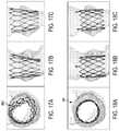
- FIGS. 14A to 18Cillustrate comparative modeling of radial inward compressive loading of prosthetic valves, according to some embodiments.
- FIG. 19show optional features of commissure posts, according to some embodiments.
- FIGS. 20 to 23show optional constraint eyelets for prosthetic valve frames, according to some embodiments.
- FIGS. 24 to 27are illustrative of offset intersection locations on prosthetic valve frames, according to some embodiments.
- FIGS. 28 to 31are illustrative of attachment features for prosthetic valves, according to some embodiments.
- FIGS. 32 to 34are illustrative of distal row frame element features for prosthetic valves, according to some embodiments.
- FIGS. 35 to 36Care illustrative of constraint guide features for prosthetic valves, according to some embodiments.
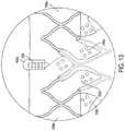
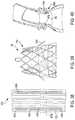
- FIGS. 37 to 40are illustrative of anchor member features for prosthetic valves, according to some embodiments.
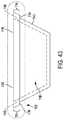
- FIGS. 41 to 43are illustrative of potential modifications for commissure attachment regions of prosthetic valves, according to some embodiments.
- FIGS. 44 and 45are illustrative of methods of delivering prosthetic valves to treatment locations, according to some embodiments.
- the present disclosurerelates to prosthetic valves used for cardiac valve replacement (e.g., for treating a failing or otherwise defective aortic or mitral valve) or other applications associated with native valve or other valve orifices, and related systems, methods, and apparatuses.
- the prosthetic valveis utilized to treat valve stenosis (e.g., aortic valve stenosis) and/or valve insufficiency (e.g., aortic valve insufficiency).
- the prosthetic valveis operable as a one-way prosthetic valve that defines a valve orifice into which leaflets open to permit flow and close so as to block or occlude the valve orifice and partially or entirely prevent flow in response to differential fluid pressure.
- Implantable valve orificesinclude anatomical structures into which a prosthetic valve can be placed and include, but are not limited to, a location from which a cardiac valve may or may not have been surgically removed.
- Other anatomical structures that can receive a prosthetic valveinclude, but are not limited to, veins, arteries, ducts, and shunts, for example.
- a valve orifice or implant sitemay also refer to a location in a synthetic or biological conduit that may receive a prosthetic valve.
- distalis used in the disclosure to refer to the outflow end (distal end) or outflow direction of a prosthetic valve
- proximalis used to refer to the inflow end of a prosthetic valve, or a direction opposite the direction of primary flow through the prosthetic valve.
- FIG. 1is an isometric view of a prosthetic valve 100 and FIG. 2 is a side view of the prosthetic valve 100 , according to some embodiments.
- the prosthetic valve 100includes a support structure 102 (also described as a frame assembly), a leaflet construct 104 (also described as a leaflet assembly), and a sealing construct 106 (also described as a sealing cuff).
- a support structure 102also described as a frame assembly
- a leaflet construct 104also described as a leaflet assembly
- a sealing construct 106also described as a sealing cuff
- the prosthetic valve 100defines a central longitudinal axis Xv, an inner side 108 ( FIG. 1 ) corresponding to a central lumen and an outer side 110 ( FIG. 1 ) corresponding to the exterior of the prosthetic valve 100 and extends from a proximal end 112 ( FIG. 2 ) to a distal end 114 ( FIG. 2 ).
- the prosthetic valve 100also has an inflow side I s ( FIG. 2 ) into which fluid (e.g., blood) flows and an outflow side O s ( FIG. 2 ) out of which blood flows.
- the leaflet construct 104 of the prosthetic valve 100has free edges that flatten together (e.g., in a Y-shaped pattern in the case of three leaflets when viewed from the top), which can also be described as coaptation of the leaflet construct 104 prosthetic valve 100 .
- the prosthetic valve 100closes. The prosthetic valve 100 closes in this fashion when the pressure of the blood on the outflow side O s ( FIG. 2 ) is greater than the pressure of the blood on the inflow side I s ( FIG. 2 ) of the prosthetic valve 100 .
- leaflet construct 104moves apart to open the prosthetic valve 100 and to let blood flow through the prosthetic valve 100 from the inflow side I s when the pressure of the blood on the inflow side I s of the prosthetic valve 100 is greater than the pressure on the outflow side O s of the prosthetic valve 100 .
- the support structure 102 of the prosthetic valve 100includes a frame 1102 (also described as a framework), a cover 1104 (also described as an attachment element), and a plurality of constraint retainers 1106 (also described as constraint guides).
- the support structure 102serves to operatively support the leaflet construct 104 in a desired location within a patient (not shown), provides features for securing and maintaining the prosthetic valve 100 to a delivery system (not shown), and other additional or alternative features as desired.
- FIG. 3is a side view of the frame 1102 of the support structure 102 at a first rotational orientation and FIG. 4 is a side view of the frame 1102 at a second rotational orientation, according to some embodiments.
- the frame 1102and thus the support structure 102 along with the leaflet construct 104 , is optionally collapsible to a reduced profile, delivery configuration and then expandable (e.g., self-expanding or expanded by the application of an internal force, such as by balloon expansion) in situ.
- expandablee.g., self-expanding or expanded by the application of an internal force, such as by balloon expansion
- the frame 1102is optionally annular, defining a tapered cylinder (e.g., a cone), also described as a tapered cylindrical shape, and has a central longitudinal axis Xf, which corresponds to and is coaxial with the central longitudinal axis of the prosthetic valve Xv ( FIG. 2 ) and is described interchangeably as the central longitudinal axis Xf of the support structure 102 , according to some embodiments.
- a tapered cylindere.g., a cone
- Xfcentral longitudinal axis
- the tapered shape of the frame 1102may be beneficial for a variety of reasons.
- the frame 1102generally defines a circular transverse cross-section in an unloaded state (e.g., when not under a transverse load), it should be understood that any variety of cross-sections (e.g., oval- or rectangular-shaped) are also contemplated.
- the frame 1102has an inner side 1110 and an outer side 1112 opposite the inner side 1110 .
- the inner side 1110faces toward the central longitudinal axis Xf, and the outer side 1112 faces outwardly, or away from the central longitudinal axis Xf.
- the frame 1102extends from a distal end 1114 (also described as an outflow end) to a proximal end 1116 (also described as an inflow end), the distal end 1114 having a first diameter and the proximal end 1116 having a second larger diameter such that the frame 1102 has a diametric taper of decreasing diameter in a distal direction between the distal end 1114 and the proximal end 1116 , the diametric taper defining a taper angle 1118 relative to the central longitudinal axis Xf of the frame 1102 (as well as relative to a right angle cylinder) when the frame 1102 , and the prosthetic valve 100 , is in an unloaded state.
- the taper angle 1118is relatively constant (linear), although non-constant tapers (e.g., varies with one or more curved or angled segments) are contemplated, as further described.
- the frame 1102includes a plurality of commissure posts 1120 and a plurality of frame members 1122 .
- the plurality of commissure postsare generally located toward, and are configured to support a region of the leaflet construct 104 that coapts, or a coaptation region of the leaflet construct 104 .
- the plurality of frame members 1122generally define a collapsible and expandable arrangement, and also serve to support one or more portions of the leaflet construct 104 as desired.
- the plurality of commissure posts 1120are spaced from one another, and arranged at desired locations around a circumference of the frame 1102 . As shown, the plurality of commissure posts 1120 are angled inwardly toward the central longitudinal axis Xf, following the taper angle 1118 , although other configurations (e.g., angled more inwardly, non-angled or angled outwardly from the central longitudinal axis Xf) are also contemplated. Although as best seen in FIG. 4 , three commissure posts 1120 are shown, any number of commissure posts are contemplated. The plurality of commissure posts 1120 define circumferentially-adjacent ones, or simply adjacent ones of the plurality of commissure posts 1120 moving about the perimeter of the frame 1102 .
- each of the commissure posts 1120has a similar design, although examples where the commissure posts 1120 differ from one another in various respects are also contemplated. Regardless, for ease of understanding, the features of each of the commissure posts 1120 will be described in association with a first commissure post 1120 a , enlarged views of which is shown in FIGS. 5 and 6 .
- first commissure post 1120 awill generally be referenced with a numeral followed by an “a.” Similar features of a second commissure post may be subsequently referenced with the same numeral as the first commissure post, but followed by a “b.” Similar features of a third commissure post may be subsequently referenced with the same numeral as the first commissure post 1120 a , but followed by a “c.” Similarly, when features of each of the plurality of commissure posts 1120 are referenced collectively, those features are referenced with the same numeral as identified for the first commissure post 1120 a , but not followed by a letter.
- the first commissure post 1120 aincludes a first leg 1130 a , a second leg 1132 a , a first slot 1134 a , which can also be described as a first post slot, and a second slot 1136 a , which can also be described as a second post slot.
- the first slot 1134 a and the second slot 1136 aare each located between the first leg 1130 a and the second leg 1132 a .
- the first commissure post 1120 aalso includes an intermediate leg 1138 a positioned between the first leg 1130 a and the second leg 1132 a .
- the first commissure post 1120 adefines the first slot 1134 a between the first leg 1130 a and the intermediate leg 1138 a and the second slot 1136 a between the second leg 1132 a and the intermediate leg 1138 a .
- the first commissure post 1120 ahas an outer side corresponding to the frame outer side 1112 ( FIG. 3 ) and a post inner side corresponding to the frame inner side 1110 ( FIG. 3 ).
- first leg 1130 a and the second leg 1132 aextend longitudinally, or in a longitudinal direction. As shown in FIG. 6 , the first leg 1130 a and the second leg 1132 a ( FIG. 5 ) extend in a longitudinal direction that is parallel to the taper angle 1118 of the frame 1102 ( FIG. 3 ). In other examples, the first leg 1130 a and the second leg 1132 a extend longitudinally, but at a different angular offset relative to the central longitudinal axis Xf (e.g., parallel, more inwardly offset, or more outwardly offset.
- each of the first slot 1134 a and the second slot 1136 aextends through a thickness of the first commissure post 1120 a , from the inner side 1110 of the frame 1102 to the outer side 1112 of the frame 1102 .
- the slots 1134 a , 1136 aare formed through the frame in a generally radial direction relative to a central longitudinal axis Xf ( FIG. 2 ) of the frame 1102 .
- one or both of the first slot 1134 a and the second slot 1136 aextend in a longitudinal direction, although the first slot 1134 a and the second slot 1136 a generally follow the taper angle 1118 .
- first slot 1134 a and the second slot 1136 aextend longitudinally, but at some offset relative (e.g., angularly offset relative to the taper angle 1118 and/or angularly offset transversely relative to the central longitudinal axis Xf).
- first slot 1134 a and the second slot 1136 aare elongate in shape, with lengths, or heights, much greater than their widths (e.g., more than 2 ⁇ , 5 ⁇ , 10 ⁇ , 20 ⁇ , or 30 ⁇ , although a variety of dimensions are suitable).
- the first slot 1134 aextends from a first end 1140 a to a second end 1142 a and the second slot 1136 a extends from a first end 1144 a to a second end 1146 a .
- the first ends 1140 a , 1144 aare open and the second ends 1142 a , 1146 a are closed.
- first ends 1140 a , 1144 aare “open” in the sense that it opens to a much wider area in the frame 1102 (e.g., more than 5 ⁇ , 10 ⁇ , or 20 ⁇ ), whereas the second ends 1142 a , 1146 a are “closed” in the sense that it terminates at the width of the first slot 1134 a and the second slot 1136 a .
- the widths of the first slot 1134 a and the second slot 1136 aare generally selected to allow a desired number of passes or loops of leaflet material through the first slot 1134 a and the second slot 1136 a , as subsequently described.
- the first commissure post 1120 adefines a distal end 1150 a that is rounded and otherwise configured to be atraumatic to tissue.
- the plurality of commissure posts 120 , and in particular the distal ends (e.g., distal end 1150 a ) of the plurality of commissure posts 1120also extend distally to define a commissure post distal boundary 1152 ( FIG. 4 ).
- the commissure post distal boundary 1152approximates a distal boundary of the leaflet construct 104 , which is attached to the commissure posts 1120 .
- the plurality of frame members 1122define a collapsible (e.g., elastically) and expandable (e.g., self-expanding or balloon expandable) framework, and also serve to support one or more portions of the leaflet construct 104 as desired. As shown in FIG. 3 , the plurality of frame members 1122 define a plurality of rows of frame members 1224 defining an undulating, alternating pattern of proximal-facing apices 242 pointing in a proximal direction and distal-facing apices 238 pointing in a distal direction.
- the plurality of rows of frame members 1224include a proximal row 1230 toward the proximal end 1116 of the frame 1102 a distal row 1232 toward the distal end 1114 of the frame 1102 , and at least one intermediate row 1234 positioned intermediate the distal row 1232 and proximal row 1230 .
- there are four rows of frame members 1224although greater or fewer numbers are contemplated (e.g., 2, 4, 12, 20).
- the distal row 1232 of the plurality of rows of frame members 1224extends distally to define a frame member distal boundary 1236 .
- the commissure post distal boundary 1152is located distal to the frame member distal boundary 1236 , with the plurality of commissure posts 1120 generally extending more distally than the plurality of rows of frame members 1224 .
- such a configurationleaves portions of the leaflet construct 104 ( FIG.
- leaflet construct 104extends distal to the frame member distal boundary 1236 .
- Such a featuremay provide additional circumferential space for the plurality of commissure posts 120 to fit into when the prosthetic valve 100 is diametrically compacted into a reduced diameter, delivery configuration.
- the plurality of rows of frame members 1224each define an undulating pattern of distal-facing apices 238 each having an apex angle 240 and proximal-facing apices 242 each having an apex angle 244 .
- the distal-facing apices 238point in the distal direction and the proximal-facing apices 242 point in the proximal direction.
- each of the apex angles 240 of each of the distal-facing apices 238has a value that is approximately the same in more than one of the plurality of rows of frame members 1224 (e.g., the same approximate value in each of the distal row of frame members 1232 , the proximal row of frame members 1230 , and/or the intermediate row of frame members 1234 ).
- each the apex angles 240are within 10% of a common apex angle defined by the plurality of rows of distal-facing apices 238 .
- each of the apex anglesis within 5%, 15%, 20%, or some other value of a common apex angle.
- the common apex angleis 30 degrees, although any of a variety of common apex angles is contemplated (e.g., 10, 15, 20, 30, 40, 45, 50, 60, 90 degrees and ranges between any of those vales).
- each of the apex angles 244 of each of the proximal-facing apices 242has a value that is approximately the same in more than one of the plurality of rows of frame members 1224 (e.g., the same approximate value in the distal row of frame members 1232 , the proximal row of frame members 1230 , and/or the intermediate row of frame members 1234 ).
- each of the apex angles 244are within 10% of a common apex angle defined by the plurality of rows of proximal-facing apices 242 .
- each of the apex anglesis within 5%, 15%, 20%, or some other value of a common apex angle.
- the common apex angleis 30 degrees, although any of a variety of common apex angles is contemplated (e.g., 10, 15, 20, 30, 40, 45, 50, 60, 90 degrees and ranges between any of those values).
- the apex angles 240 and/or the apex angles 244 of one or more columns of closed cells 1238 defined by the plurality of frame members 1224are approximately the same as another one of the columns of closed cells 1238 .
- the apex angles of one or more columnsis optionally within 10% of a common apex angle defined by the one or more columns of closed cells 1238 of proximal-facing apices 242 and/or distal-facing apices 238 .
- each of the apex anglesis within 5%, 15%, 20%, or some other value of a common apex angle.
- the common apex angleis 30 degrees, although any of a variety of common apex angles is contemplated (e.g., 10, 15, 20, 30, 40, 45, 50, 60, 90 degrees and ranges between any of those values).
- the frame 1102also includes a plurality of rows of closed cells 1240 defined by the plurality of frame members 1224 .
- the plurality of rows of frame members 1224generally intersect with one another at intersection locations P to define the plurality of rows of closed cells 1240 .
- each of the plurality of rows of closed cells 1240has a proximal end 1242 , a distal end 1244 , and a cell height 1246 between the distal end 1244 and the proximal end 1242 and a cell width 1248 perpendicular to the cell height 1246 .
- each of the plurality of rows of closed cellshas a first lateral-facing apex 250 defining an apex angle 252 and a second lateral facing-apex 254 opposite the first lateral-facing apex 250 and defining an apex angle 256 .
- each of the apex angles 252 and/or apex angles 256 ofhas approximately the same value between one or more of the plurality of rows of closed cells 1240 and/or columns of closed cells 1238 (e.g., within 10% of a common apex angle, although other values such as values within 5%, 15%, 20%, or some other value of a common apex angle are contemplated).
- the common apex angleis 30 degrees, although any of a variety of common apex angles is contemplated (e.g., 10, 15, 20, 30, 40, 45, 50, 60, 90 degrees and ranges between any of those values).
- the apex angles 240 and/or the apex angles 244 of one or more of the plurality of columns of closed cells 1238 and/or one or more of the plurality of rows of the closed cells 1240are approximately the same as another one of the plurality of columns of closed cells 1238 and/or the plurality of rows of the closed cells 1240 (e.g., within 10% of a common apex angle, although other values such as values within 5%, 15%, 20%, or some other value of a common apex angle are contemplated).
- the common apex angleis 30 degrees, although any of a variety of common apex angles is contemplated (e.g., 10, 15, 20, 30, 40, 45, 50, 60, 90 degrees and ranges between any of those values).
- the plurality of rows of closed cells 1240includes a proximal row of closed cells 1250 at the proximal end 1116 of the frame portion 1210 , a distal row of closed cells 1252 toward the distal end 1114 of the frame portion 1210 , and at least one intermediate row of closed cells 1253 intermediate the distal row of closed cells 1252 and the proximal row of closed cells 1250 .
- three rows of closed cells 1240are shown, greater or fewer numbers are contemplated (e.g., greater or few number of intermediate rows of closed cells 1253 ).
- the cell heights 1246 of the distal row of closed cells 1252are each less than the cell heights 1246 of the proximal row of closed cells 1250 . Additionally, each of the cell heights 1246 of the intermediate row of closed cells 1253 are less than the cell heights 1246 of the proximal row of closed cells 1250 and greater than the cell heights 1246 of the distal row of closed cells 1252 .
- the cell widths 1248 of the distal row of closed cells 1252are each less than the cell widths 1248 of the proximal row of closed cells 1250 . Additionally, each of the cell widths 1248 of the intermediate row of closed cells 1253 are less than the cell widths 1248 of the proximal row of closed cells 1250 and greater than the cell widths 1248 of the distal row of closed cells 1252 .
- the various apex anglese.g., the apex angles 240 , the apex angles 244 , the apex angles 252 , and/or the apex angles 256
- the apex angles 244be within 10% of one another
- the apex angles 252be within 10% of one another
- the apex angles 256be within about 10% of one another
- increasing the cell heights 1246 and increasing cell widths 1248 in a proximal directionhelps balance compaction forces needed toward the proximal end 1116 relative to the compaction forces necessary at the distal end 1114 for diametrically compacting the prosthetic valve 100 to a compact delivery configuration.
- the compaction forces required toward the proximal end 1116are substantially the same as, or less than, the compaction forces required toward the distal end of the prosthetic valve 100 .
- FIG. 7shows additional features for the frame 1102 of the support structure 102 , according to some embodiments.
- the foregoing description of the frame 1102applies fully to the frame 1102 shown in FIG. 7 .
- the additional features shown for the frame 1102 in FIG. 7include a more curved shape for the frame members 1122 as a result of a non-linear change in the cell widths 1248 along the cell heights 1246 (e.g., as compared to the straighter pattern shown in FIGS. 3 and 4 ) and the diametric taper exhibited by the frame 1102 , which is shown to include three, distinct tapers, as opposed to a single taper shown in FIGS. 3 and 4 for the frame 1102 .
- the apex angles 240 , the apex angles 244 , the apex angles 252 , and the apex angles 256are determined by drawing straight lines between the various apices of the plurality of rows of closed cells 1240 .
- the frame 1102includes a diametric taper in which the taper angle varies 1118 between the distal end 1114 and the proximal end 1116 relative to the central longitudinal axis Xf of the frame 1102 when the prosthetic valve 100 is in an unconstrained, or unloaded state.
- the taper angle 1118optionally includes a distal taper angle 1300 corresponding to the plurality of commissure posts 1120 , a proximal taper angle 1302 corresponding to the proximal row 1230 of the plurality of rows of frame members 1224 , and an intermediate taper angle 1304 between the distal taper angle 1300 and the proximal taper angle 1302 that is defined by the intermediate rows 1234 and the distal row 1232 , according to some embodiments.
- the distal taper angle 1300is greater than the intermediate taper angle 1304 , and the intermediate taper angle 1304 is greater than the proximal taper angle 1302 .
- one or more of the distal taper angle 1300 , the intermediate taper angle 1304 , and the proximal taper angle 1302is the same.
- the proximal taper angleis zero (e.g., parallel to the central longitudinal axis Xf of the frame 1102 ).
- FIG. 8is an end view of the frame 1102 from the distal end 1114 and FIG. 9 is a side view of the frame 1102 , both of which show the frame 1102 in a diametrically compacted, delivery state.
- FIGS. 8 and 9are illustrative of compaction of the prosthetic valve 100 , according to some embodiments.
- the taper angle 1118FIG. 7
- the taper angle 1118includes a more inward taper angle toward the central longitudinal axis Xf at both the distal end 1114 and/or the proximal end 1116 than the intermediate portion of the diametric taper as desired.
- Such proximally tapering designscan be particularly helpful in delivering the prosthetic valve 100 from a delivery system (not shown) when in a diametrically compacted state (e.g., from a sheath of a delivery system or otherwise constrained on a delivery catheter), including avoiding damage to the anatomy during delivery, snagging on the anatomy and/or delivery system, facilitating repositioning or retrieval, or other advantages. Such advantages may also be present when the prosthetic valve 100 is partially or fully deployed. And, a distally tapering design may also assist with such delivery and also help with retraction and/or reorientation of the prosthetic valve 100 , including when the prosthetic valve 100 is diametrically compacted and/or partially or fully deployed.
- the frame 1102can be etched, cut, laser cut, stamped, three-dimensional printed or wire wound, among other suitable processes.
- the frame 1102can include any metallic or polymeric material, such as an elastically (e.g., nitinol) or plastically (e.g., stainless steel) deformable metallic or polymeric material that is generally biocompatible.
- frame 1102Other materials suitable for the frame 1102 include, but are not limited to, other titanium alloys, stainless steel, cobalt-nickel alloy, polypropylene, acetyl homopolymer, acetyl copolymer, a drawn filled tube (e.g., nitinol wire with a platinum core), other alloys or polymers, or any other material that is generally biocompatible having adequate physical and mechanical properties to function as a frame 1102 as described herein.
- other titanium alloysstainless steel, cobalt-nickel alloy, polypropylene, acetyl homopolymer, acetyl copolymer, a drawn filled tube (e.g., nitinol wire with a platinum core), other alloys or polymers, or any other material that is generally biocompatible having adequate physical and mechanical properties to function as a frame 1102 as described herein.
- the cover 1104optionally includes one or more layers of material, such as a membrane, or film material, secured to the frame 1102 .
- the coverincludes of one or more layers of ePTFE material, although any of a variety of other suitable materials may be employed as desired, including fluoropolymer materials such as PTFE, ePTFE, FEP, and others.
- the cover 1104optionally assists with sealing the prosthetic valve 100 to the surrounding conduit in which it is placed (e.g., valve orifice) and also with securing the leaflet construct 104 to the support structure 102 , as subsequently described.
- the cover 1104has one or more rows of apertures 1270 for receiving one or more constraints (such as the constraint 1272 shown in broken lines in FIG. 1 ) associated with a transcatheter delivery system 6000 as shown in FIG. 32 .
- suitable transcatheter delivery systems for use as the transcatheter delivery system 6000can also be found in U.S. Provisional Application Ser. No. 62/579,756, entitled “TRANSCATHETER DEPLOYMENT SYSTEMS AND ASSOCIATED METHODS,” filed by Applicant on Oct. 31, 2017, as well as U.S. Provisional Application Ser. No. 62/682,692, entitled “TRANSCATHETER DEPLOYMENT SYSTEMS AND ASSOCIATED METHODS,” filed by Applicant on Jun. 8, 2018.
- constraintsare optionally employed (e.g., as shown in FIG. 32 three constraints 1272 are generally indicated in broken lines at positions corresponding to the rows of apertures 1270 and the constraint retainers 1106 shown in FIG. 1 ).
- constraintssuch as the constraint 1272 , are optionally formed of a filamentary material (e.g., a filament, strand, wire, combinations thereof, and the like).
- the prosthetic valve 100also optionally includes one or more constraint retainers 1106 formed as a loop of material coupled to the support structure 102 (e.g., secured to one or more of the plurality of frame members 1122 ).
- the constraint retainers 1106are each formed by one or more loops of material, such as polymeric material (e.g., ePTFE fiber), metallic material (e.g., nitinol), or any other material that is biocompatible and suitable for implantation with the prosthetic valve 100 .
- the constraint retainers 1106are formed of filamentary material, such as a filament, strand, or a wire (e.g., polymeric or metallic).
- one or more of the constraint retainers 1106are formed of a biocorridible or biodegradable material that biocorrodes or bioabsorbs over time following implantation. As shown, the constraint 1272 passes through the constraint retainers 1106 to help secure the constraint 1272 in place and help prevent the constraint 1272 from slipping off the distal end 1114 of the frame 1102 .
- the leaflet construct 104can be received within and coupled to the support structure 102 using any of a variety of techniques (e.g., bonding, adhering, sewing, and others).
- the location or position of the leaflet construct 104 along the length of the prosthetic valve 100is referenced as a leaflet region or leaflet portion of the prosthetic valve 100 .
- the various embodiments described hereinmay utilize biological, such as bovine or porcine, or synthetic leaflets, such fluoropolymer leaflet constructs.
- Various embodimentshave been found to be advantageous for use with synthetic leaflets, such as fluoropolymer constructs, including for wash out and reduced thrombosis, secure and reliable leaflet construct attachment, and others.
- suitable leaflet constructscan also be found in US 2015/0224231 to Bruchman et al., published Aug. 13, 2015.
- FIG. 10is an enlarged view of a portion of the support structure 102 between two adjacent commissure posts 1120 of the frame 1102 , according to some embodiments. Similar portions of the support structure 102 are defined between each of the adjacent plurality of commissure posts 1120 , according to some embodiments and thus are described collectively with reference to FIG. 10 .
- the portion of the support structure 102is represented in a flattened form for ease of illustration, although it should be understood that the support structure 102 is three-dimensional and generally annular. As shown, the support structure 102 defines a first leaflet attachment region 1160 a between the first commissure post 1120 a and the second commissure post 1120 b , as well as leaflet attachment regions 1160 between the remaining commissure posts 1120 .
- the leaflet attachment frame members 1170 and the cover 1104are arranged to support the leaflet construct 104 and to help define a leaflet shapes of the leaflet construct 104 .
- the plurality of frame members 1122 of the frame 1102include a plurality of leaflet attachment frame members 1170 , or simply leaflet attachment elements, that together with the cover 1104 define the leaflet attachment regions of the prosthetic valve 100 , including the first leaflet attachment region 1160 a shown in FIG. 10 .
- Each of the leaflet attachment regionsis optionally substantially similar and thus are described collectively with regard to the first leaflet attachment region 1160 a.
- the first leaflet attachment region 1160 adefines a first side 1162 a , a second side 1164 a , and a base 1166 a , which is defined at least in part by the cover 1104 . As referenced, similar leaflet attachment regions are defined between each of the plurality of commissure posts 1120 , according to some embodiments.
- each of the plurality of leaflets 1180has a similar design, although examples where the leaflets differ from one another in various respects are also contemplated. Regardless, for ease of understanding, the features of each of the leaflets 1180 will be described in association with a first leaflet 1180 a .
- first leaflet 1180 awill generally be referenced with a numeral followed by an “a.” Similar features of a second leaflet may be subsequently referenced with the same numeral as the first leaflet, but followed by a “b.” Similar features of a third leaflet may be subsequently referenced with the same numeral as the first leaflet 1180 a , but followed by a “c.” Similarly, when features of each of the leaflets are referenced collectively, those features are referenced with the same numeral, but not followed by a letter. Similarly, when features of each of the leaflets 1180 are referenced collectively, those features are referenced with the same numeral, but not followed by a letter.
- FIG. 11is a flat view of the first leaflet 1180 a of the leaflet construct 104 .
- the first leaflet 1180 ais shown from a flattened, plan view prior to assembly with the support structure 102 .
- This flattened plan viewcan also be described as a cut pattern, or simply a leaflet pattern. From FIG. 11 , for example, it should be understood that the leaflet construct 104 is folded and turned into a non-planar shape following attachment to portions of the support structure 102 , with each of the plurality of leaflets 1180 being attached circumferentially about the support structure 102 .
- FIG. 11for example, it should be understood that the leaflet construct 104 is folded and turned into a non-planar shape following attachment to portions of the support structure 102 , with each of the plurality of leaflets 1180 being attached circumferentially about the support structure 102 .
- FIG. 11is a flat view of the first leaflet 1180 a of the leaflet construct 104 .
- the plurality of leaflets 1180are optionally formed as separate components, which are then separately assembled to the support structure 102 , although interconnected, continuous leaflet designs are also contemplated. As shown, the plurality of leaflets 1180 are spaced from one another, and arranged, or otherwise distributed at desired locations around a circumference of the leaflet construct 104 .
- each of the leaflets 1180define circumferentially-adjacent ones, or simply adjacent ones of the plurality of leaflets 1180 moving about the circumference of the leaflet construct 104 .
- the leaflet construct 104can be formed in a variety of manners, including cutting a cylinder of polymer material into a desired shape, cutting a sheet of polymer material into a desired shape, and/or molding (e.g., compression or injection molding) the leaflet construct 104 with a desired shape.
- the first leaflet 1180 aoptionally includes a body portion 1190 a , a plurality of attachment tabs 1192 a extending from the body portion 1190 a , a first commissure tab 1194 a extending from the body portion 1190 a , and a second commissure tab 1196 a extending from the body portion 1190 a.
- the body portion 1190 aalso described as a leaflet body, is bounded in broken lines for understanding purposes.
- the body portion 1190 a of the first leaflet 1180 ais the moving portion of the first leaflet 1180 a in the prosthetic valve 100 ( FIG. 1 ).
- the boundaries of the body portion 1190 aare defined and the body portion 1190 a takes on a three dimensional shape, rather than the flat shape shown in FIG. 11 .
- the broken linesare provided for general visualization purposes of the body portion 1190 a .
- the shape of the body portion 1190 ais generally dictated by the lines, or areas of attachment to the support structure 102 .
- the edges of the body portion 1190 agenerally correspond to fold lines where the attachment tabs 1192 a and first commissure tab 1194 a and the second commissure tab 1196 a are secured to the support structure 102 .
- the leaflet construct 104may be attached to the support structure 102 using cover 1104 ( FIG. 10 ), which in turn, may contribute to shape defined by the leaflet attachment regions 1160 and the ultimate shape of the body portion 1190 a.
- the body portion 1190 a of the first leaflet 1180 ahas the general shape of an isosceles trapezoid. Regardless of the exact shape, the body portion 1190 a generally has a first side 1200 a , a second side 1202 a , a leaflet base 1204 a , and a free edge 1206 a opposite the leaflet base 1204 a .
- the body portion 1190 ais configured to facilitate coaptating of the first leaflet 1180 a with the other leaflets 1180 .
- the shape of the body portion 1190 acorresponds to the sides and base of the first leaflet attachment region 1160 a ( FIG. 10 ).
- leaflet base 1204 acan be considered to be flat and to extend perpendicular to the central longitudinal axis Xf of the support structure 102 following assembly, although a variety of configurations are contemplated, including leaflet bases that are not flat in the transverse plane.
- the body portion 1190 ais shown to take on the general shape of an isosceles trapezoid, any number of shapes is contemplated, and the body portion 1190 a need not be trapezoidal in overall appearance.
- the body portion 1190 amay include a central region that defines a shape substantially that of an isosceles trapezoid, with side regions on each side that have a shape substantially that of a triangle.
- the body portion 1190 amay outline a shape that can be described as U-shaped or a V-shapes, depending on the geometric outline defined by the first leaflet attachment region 1160 a.
- the first leaflet 1180 agenerally defines a fold over portion 1198 a , also described as a fold over region, outside of the body portion 1190 a , as demarcated by the broken line in FIG. 11 .
- the fold over portion 1198 a of the first leaflet 1180 ais the portion that is used to secure the first leaflet 1180 a to the support structure 102 , where the remaining leaflets 1180 optionally include similar features for securing to the frame 1102 .
- the leaflet attachment frame members 1170( FIG. 10 ) fit into a fold that is formed between the body portion 1190 a and the fold over portion 1198 a .
- the margin of the body portion 1190 a adjacent to the support structure 102extends radially inward from the frame 1102 when coupled to the frame 1102 .
- the body portion 1190 aincludes enough material between the commissure posts 1120 of the frame 1102 so that the leaflet free edges can come together or coapt in the interior of the prosthetic valve 100 to close the prosthetic valve 100 .
- the plurality of attachment tabs 1192 a located in the fold over portion 1198 aare positioned about a perimeter of the body portion 1190 a and are separated from one another by openings 1208 a for receiving frame members 1122 (e.g., leaflet attachment frame members 1170 ) of the frame 1102 .
- one or more of the plurality of attachment tabs 1192 aoptionally includes apertures 1199 a through the thickness of the attachment tabs 1192 a .
- the apertures 1199 amay assist with securing the attachment tabs 1192 a to the support structure 102 (e.g., to the frame 1102 and the cover 1104 ) using adhesives or bonding (e.g., to provide additional surface area for adhesion/bonding), fastening elements (e.g., holes for sutures), or combinations thereof.
- the apertures 1199 aare used for alignment purposes, such as to help align one attachment tab (e.g., one of the attachment tabs 1192 a of the first leaflet 1180 a ) over another attachment tab of another leaflet (e.g., one of the attachment tabs 1192 b of the second leaflet 1180 b ) when folding the attachment tabs onto the support structure 102 .
- Similar or additional apertures 1199 amay additionally or alternatively be incorporated to reduce mass of the material forming the leaflets 1180 , to increase mechanical entanglement of the material forming the leaflets 1180 and any bonding materials used to secure the leaflets 1180 to the support structure 102 , or for additional or alternative purposes as desired.
- first commissure tab 1194 a and the second commissure tab 1196 aassist with securing the first leaflet 1180 a to the first commissure post 1120 a and second commissure post 1120 b ( FIG. 2 ).
- first commissure tab 1194 aextends from the first side 1200 a of the body portion 1190 a and the second commissure tab 1196 a extends from a second side 1202 a of the body portion 1190 a .
- the first commissure tab 1194 aextends from a first end 1210 a , also described as a leaflet end, to a terminal end 1212 a .
- the second commissure tab 1196 aextends from a first end 1214 a to a terminal end 1216 a .
- the first commissure tab 1194 a and the second commissure tab 1196 aare shown as generally rectangular in shape, with a constant width, although tapers (e.g., toward the terminal ends 1212 a , 1216 a ) are also contemplated.
- the first leaflet 1180 aincludes a plurality of first retaining elements 1184 a and a plurality of second retaining elements 1186 a . As shown in FIG. 11 , the first leaflet 1180 a includes a plurality of first retaining elements 1184 a , and a plurality of second retaining elements 1186 a .
- a retaining elementincludes one or more of a strand, filament, monofilament, multifilament (whether braided, woven, twisted or an otherwise associated group of filaments), a bead of material, a thread, a suture, a rolled film, a multilayer lay-up of material, a wire, an embossed or other feature providing the functionality described herein.
- the first retaining elements 1184 a and/or the second retaining elements 1186 acan be formed from polymeric or metallic materials, fluoropolymers, one or more of FEP, PEEK, ePTFE filament(s) (mono- or multi-), nitinol, stainless steel, multiple folds or layers of material (e.g., ePTFE film), combinations thereof, or any of a variety of features configured to resist movement relative to the slot(s).
- the first and second retaining elements 1184 a , 1186 aare optionally molded, heat bonded, or otherwise coupled to the leaflet construct 104 as desired.
- couplemeans to join, connect, attach, adhere, affix, or bond, whether directly or indirectly, and whether permanently or temporarily.
- the first leaflet 1180 aincludes first retaining elements 1184 a that are located on each of the first commissure tab 1194 a and the second commissure tab 1196 a . As shown, the first leaflet 1180 a also includes second retaining elements 1186 a that are located on each of the first commissure tab 1194 a and the second commissure tab 1196 a.
- first retaining elements 1184 aare spaced apart from their adjacent second retaining elements 1186 a a distance at least as wide as the thickness of a corresponding commissure post 1120 (e.g., 1120 a ) as measured from the inner side 1110 to the outer side 1112 of the frame 1102 .
- the various retaining elementscan take a variety of forms.
- one or both of the first and second retaining elements 1184 , 1186are formed as beads of material and/or fibers (e.g., coated fibers) on the commissure tabs of the leaflets 1180 .
- the various retaining elementsare optionally bonded to the underlying material of the leaflets 1180 , such as by thermal bonding.
- FIG. 12is illustrative of a leaflet attachment configuration between the plurality of leaflets 1180 and the plurality of commissure posts 1120 of the prosthetic valve 100 .
- FIG. 12shows the first commissure post 1120 a , with one side of the first leaflet 1180 a and one side of the second leaflet 1180 b attached thereto, it should be understood that similar attachment methods are used to attach the remaining commissure tabs of the plurality of leaflets 1180 to respective ones of the remaining commissure posts 1120 .
- the first commissure tab 1194 a of the first leaflet 1180 aextends through the first slot 1134 a a plurality of times (also described as a plurality of passes) and the second commissure tab 1196 b of the second leaflet 1180 b extends through the second slot 1136 a of the first commissure post 1120 a a plurality of times (also described as a plurality of passes), with the first retaining elements 1184 a , 1184 b positioned on the outer side 1112 of the frame 1102 , and thus on the outer side 1112 of the first commissure post 1120 a.
- the second retaining elements 1186 a , 1186 bare also positioned on the outer side 1112 of the frame 1102 , and thus the outer side of the first commissure post 1120 a . As shown, the second retaining elements 1186 a , 1186 b and the plurality of passes of the first and second commissure tabs 1194 a , 1196 b , respectively, resist being pulled inwardly and outwardly relative to the frame 1102 .
- first retaining elements 1184 a , 1184 b and the plurality of passes of the first and second commissure tabs 1194 a , 1196 brespectively, cover the second retaining elements 1186 a , 1186 b and help the assembly being pulled inwardly and outwardly relative to the frame 1102 .
- the first commissure tab 1194 a of the first leaflet 1180 adefines a first pass 1250 a through the first slot 1134 a (inside-out relative to the first commissure post 1120 a ) and a second pass 1252 a through the first slot 1134 a (outside-in relative to the first commissure post 1120 a ) to define a first loop 1254 a through the first slot 1134 a .
- the second retaining element 1186 ais positioned within the first loop 1254 a to encircle the second retaining element 1186 a and form a widened cross-section for the first loop 1254 a on the outer side 1112 of the frame 1102 .
- the width of the first loop 1254 ais selected to resist, or be restrained from, pulling through the first slot 1134 a.
- the first commissure tab 1194 a of the first leaflet 1180 adefines a third pass 1256 a around the outside of the first commissure post 1120 a , from the inner side 1110 around the first side 1148 a to the outer side 1112 and then back from the outer side 1112 to the first side 1148 a to define a fourth pass 1259 a , the third and fourth passes 1256 a , 1259 a defining a second loop 1258 a passing outside the first commissure post 1120 a on the first side 1148 a .
- the first retaining element 1184 ais positioned within the second loop 1258 a to encircle the first retaining element 1184 a and form a widened cross-section for the second loop 1258 a on the outer side 1112 of the frame 1102 .
- the width of the second loop 1258 ais selected as desired (e.g., to fit against the outer side 1112 between the first leaflet 1180 a and the second leaflet 1180 b .
- the first pass 1250 ais positioned adjacent, and opposite the second pass 1252 a
- the third pass 1256 a and fourth pass 1259 aare positioned adjacent each other.
- the second commissure tab 1196 bdefines a similar set of features to those of the first commissure tab 1194 a , which are labeled on FIG. 12 for reference. As shown, the second commissure tab 1196 b of the second leaflet 1180 b defines a first pass 1250 b through the second slot 1136 a (inside-out relative to the first commissure post 1120 a ) and a second pass 1252 b through the second slot 1136 a (outside-in relative to the first commissure post 1120 a ) to define a first loop 1254 b through the second slot 1136 a .
- the second retaining element 1186 bis positioned within the first loop 1254 b to encircle the second retaining element 1186 b and form a widened cross-section for the first loop 1254 b on the outer side 1112 of the frame 1102 .
- the width of the first loop 1254 bis selected to resist, or be restrained from, pulling through the second slot 1136 a.
- the second commissure tab 1196 b of the second leaflet 1180 bdefines a third pass 1256 b around the outside of the first commissure post 1120 a , from the inner side 1110 around the second side 1149 a to the outer side 1112 and then back from the outer side 1112 to the second side 1149 a to define a fourth pass 1259 b , the third and fourth passes 1256 b , 1259 b defining a second loop 1258 b passing outside the first commissure post 1120 a on the second side 1149 a .
- the first retaining element 1184 ais positioned within the second loop 1258 a to encircle the first retaining element 1184 a and form a widened cross-section for the second loop 1258 b on the outer side 1112 of the frame 1102 .
- the width of the second loop 1258 bis selected as desired (e.g., to fit against the outer side 1112 between the first leaflet 1180 a and the second leaflet 1180 b ).
- the second retaining elements 1186 a , 1186 b , and thus the second loops 1258 a , 1258 bare secured together (e.g., with an adhesive or one or more fasteners, such as sutures or staples).
- an adhesive or one or more fastenerssuch as sutures or staples
- sutures or other filamentsare optionally used to secure the second loops 1258 a , 1258 b together.
- a secondary coupler 1290is shown in broken lines secured around the second retaining elements 1186 a , 1186 b.
- the secondary coupler 1290is a filament, such as a suture or staple, for securing the second retaining elements 1184 a , 1184 b together.
- the secondary coupler 1290includes coating(s) or layer(s) of material over molded or otherwise disposed on the exterior and/or interior side of the frame 1102 to help couple the first loops 1254 and the second loops 1258 to one another and the frame 1102 .
- any of the other loop and post arrangementsmay be coupled with one or more secondary couplers (e.g., by one or more sutures, filaments, layers, and/or coatings).
- one or more layers of tapemay be overwrapped onto first loops 1254 and/or second loops 1258 , one or more jackets or covers of material may be placed over and secured to the first loops 1254 and/or second loops 1258 , or other techniques may be employed.
- such materialsmay be selected not only to secure the first loops 1254 and the second loops 1258 in place, but may also be employed to form a continuous surface without cracks or other defects, which may help avoid tissue ingrowth and/or thrombus formation where such avoidance is desirable.
- any of the other loop and post arrangements provided in this disclosuremay be coupled with one or more secondary couplers (e.g., by one or more sutures, filaments, layers, and/or coatings).
- the second loops 1258 a , 1258 bcan help prevent the first loops 1254 a , 1254 b from pulling outwardly (radial outward) from the first commissure post 1120 a.
- the first loops 1254 a,bare optionally described as outer loops and the second loops 1258 a,b are also optionally described as outer loops.
- one or more of the passes 1250 a,b , 1252 a,b , 1256 a,b , 1259 a,bare coupled to one another (e.g., by heat seating, adhesives, sutures, or other means).
- the passescan be inserted into the first slot 1134 a and second slot 1136 a , respectively, with the first retaining elements 1184 a,b on the outer side 1112 of the frame 1102 and the second retaining elements 1186 a,b on the outer side of the frame 2102 by sliding the first and second commissure tabs 1194 a , 1196 b into the first slot 1134 a and the second slot 1136 a through open ends of the slots (not shown, but see the first commissure post 1120 a for an example).
- first and second commissure tabs 1194 a , 1196 bare threaded through the slots 1134 a , 1136 a and around the sides 1148 a , 1149 a (e.g., rather than being slid up into the slots 1134 a , 1136 a and around the first and second legs 1130 a , 1132 a ).
- the described number of passesare shown for each of the commissure tabs in FIG. 12 , fewer or greater passes are also contemplated.
- first retaining elements 1184 , second retaining elements 1186 , first loops 1254 , or second loops 1258resides on the inner side 1110 of the frame 1102 .
- those featuresare outside of the flow field and generally do not interfere with blood flow through the prosthetic valve 100 .
- the remaining commissure tabs of the leaflets 1180are secured to and supported from the remaining commissure posts 1120 .
- the relatively smooth turns and reinforcement provided by the first and second retaining elements 1184 , 1186reduce stress concentrations at the commissure posts 1120 due to transverse loading of the leaflet construct 104 and help to reduce axial stress concentrations at the attachment interfaces between the commissure posts 1120 and the leaflets 1180 .
- first leaflet 1180 a and the second leaflet 1180 bare spaced from one another at the inner side 1110 of the frame 1102 , which can be described as the leaflets defining a commissure gap 1260 at the first commissure post 1120 a .
- the prosthetic valvee.g., prosthetic valve 100
- the commissure gap 1260helps provide a limited amount of flow to pass between the first and second leaflets 1180 a , 1180 b near the frame 1102 to help avoid thrombus formation at that location (e.g., whereas a lack of a gap such as the commissure gap 1260 may create a dead flow region susceptible to such thrombosis formation).
- FIG. 13shows an overlay of portions of the prosthetic valve 100 illustrating parts of the frame 1102 , the cover 1104 , the first leaflet 1180 a and the second leaflet 1180 b of the leaflet construct 104 in an area of the first commissure post 1120 a , for understanding of assembly thereof, where similar concepts apply in assembling the remaining leaflets 1180 to the support structure 102 .
- the leaflet construct 104( FIG. 11 ) is attached to the support structure 102 using fold over portions, such as the fold over portion 1198 a ( FIG. 11 ) of the first leaflet 1180 a .
- Attachment tabssuch as the attachment tabs 1192 a , 1192 b of the first leaflet 1180 a and the second leaflet 1180 b are received through the plurality of rows of closed cells 1240 over portions of the frame 1102 and the cover 1104 and attached over the outer side 1112 of the frame 1102 and the cover 1104 to attach the leaflet construct 104 to the support structure 102 .
- the attachment tabs 1192 a , 1192 bare passed through the frame 1102 and folded onto the cover 1104 .
- the lowermost attachment tab(s) 1192 amay be folded to a relatively flat area defined by the cover 1104 (e.g., the base 1166 a shown in FIG. 10 ), to define the leaflet base 1204 a shown for the body portion 1190 a in FIG. 11 .
- the various attachment tabsare folded over at the first leaflet attachment region 1160 a , including the first side 1162 a , the second side 1164 a , and the base 1166 a ( FIG. 10 ).
- each of the plurality of leaflets 1180are then secured to the support structure 102 at each of the leaflet attachment regions 1160 between each of the plurality of commissure posts 1120 .
- the fold over portionscan be secured in place using adhesives, sutures, sintering, or by other methods as desired.
- apertures, such as the apertures 1199 aare used to assist with bonding (e.g., adhering) and/or to assist with aligning the attachment tabs at their proper positions.
- the shapes of the fold over portionsgenerally correspond to shapes of the plurality of rows of closed cells 1240 ( FIG. 7 ) to assist with proper visual alignment of the leaflet construct 104 onto the support structure.
- the sealing construct 106includes a sealing member 1500 having a secured portion 1510 that is coupled to the support structure 102 (e.g., to the cover 1104 ) and an unsecured portion 1512 that is not coupled to the support structure 102 .
- the sealing member 1500is optionally in the form of a continuous band of material extending about the circumference of the support structure 102 .
- the sealing construct 106is not shown to extend fully to the proximal end 112 of the device, although it should be understood that the sealing construct 106 optionally extends along a desired portion of the prosthetic valve 100 , including to the proximal end 112 .
- the secured portion 1510optionally includes a proximal region 1520 that is adhered, bonded or otherwise secured to the support structure 102 .
- the proximal region 1520optionally extends proximally a desired amount, including to the proximal end 112 of the prosthetic valve 100 as desired.
- the proximal region 1520( FIG. 2 ) is optionally continuous and uninterrupted (e.g., a ring) around a circumference of the support structure 102 (e.g., forming a continuous area of attachment. In other examples, the proximal region 1520 is discontinuous.
- the secured portion 1510also optionally includes one or more discrete regions 1522 ( FIG.
- the secured portion 1510also optionally includes one or more securing tabs 1524 ( FIG. 2 ) that are secured to the support structure 102 and extend longitudinally (e.g., distally) from a distal-facing edge 1532 of the sealing member 1500 .
- the unsecured portion 1512optionally includes a distal region 1530 ( FIG. 2 ) of the sealing member which extends to a distal-facing edge 1532 ( FIG. 2 ), at least a portion of which is not secured to the support structure 102 .
- the distal-facing edge 1532is free to billow, or deflect outwardly a limited amount (e.g., under positive blood pressure) to help the sealing member 1500 positively engage adjacent tissue. This feature may assist with the sealing function of the sealing member 1500 with adjacent tissue, including blocking blood flow and/or facilitating tissue ingrowth, for example.
- the discrete regions 1522 , securing tabs 1524 , or other additional or alternative featuresare optionally employed to help prevent the sealing member 1500 from inverting during deployment and/or in vivo during operation of the prosthetic valve 100 .
- the distal-facing edge 1532is secured to the support structure 102 at a plurality of locations (e.g., at the securing tabs 1524 ) and remains unsecured from the support structure 102 at a plurality of locations where the distal-facing edge 1532 is free to billow, or deflect outwardly.
- FIGS. 14 to 18show by way of example some of the advantages that are achieved with the tapered diametric profiles described above for the frame 1102 , and thus the prosthetic valve 100 .
- the leaflet bases of the leaflet construct 104e.g., such as the leaflet base 1204 a shown in FIG. 11
- the frame 1102defining a leaflet base level diameter at the first longitudinal location 1600 .
- each the leaflet construct 104is coupled to the plurality of commissure posts 1120 at a second longitudinal location 1650 along the central longitudinal axis Xf of the support structure 102 that is distal to the first longitudinal location, the frame 1102 defining a commissure level diameter at the second longitudinal location 1650 .
- the prosthetic valve 100generally defines a proximal portion 1660 proximal to the first longitudinal location 1600 and that proximal portion 1660 typically encounters a larger amount of the inward radial compressive load (e.g., a majority of the inward radial compressive load) when the prosthetic valve 100 is implanted in a native valve orifice, such as an aortic valve orifice.
- the commissure level diameteris less than the leaflet base level diameter when the frame 1102 , and thus the prosthetic valve 100 , is in an unloaded state.
- the commissure level diameteris closer in value to the leaflet base diameter when the prosthetic valve 100 is in an operational state (e.g., under an inward radial compressive load) than when the prosthetic valve 100 is in the unloaded state.
- the operational state of the prosthetic valve 100e.g., following implantation at a native valve orifice
- FIG. 14shows a deformation model for the frame 1102 under an inward radial compressive load F.
- the loadis modeled as a compressive force applied in the form of a right cylinder applied equally around an entire circumference of the frame 1102 along the entire length of the frame 1102 .
- FIG. 14Ashows the frame 1102 in an unloaded condition.
- FIG. 14Bshows the frame 1102 in a partially loaded condition under the inward radial compressive load F.
- FIG. 14Cshows the frame 1102 under a fully loaded condition (e.g., as would be expected during operation following implantation).
- the commissure level diameteris closer in value to the leaflet base diameter after the prosthetic valve 100 is placed under full loading.
- FIGS. 15 and 16help illustrate some advantages of this feature, for example when compared to a prosthetic valve with a frame that has the shape of a simple, right cylinder.
- FIG. 15Ashows an example of a prosthetic valve 2000 with a frame 2002 having the shape of a right cylinder
- FIG. 15Bshows deformation of that prosthetic valve 2000 when placed under a simulated load corresponding to a native valve orifice (e.g., with a majority placed on a proximal portion of the prosthetic valve 2000 )
- FIG. 15Cshows the resulting performance of a leaflet construct 2004 of the prosthetic valve 2000 when placed under that inward radial compressive load.
- the leaflet construct 2004shows wrinkling and less than optimal opening conditions as a result of the leaflet base diameter of the prosthetic valve 2000 being compressed inwardly a large amount so that it is relatively less than the commissure level diameter.
- FIG. 16shows expected performance of the prosthetic valve 100 under similar conditions to those described above with regard to the prosthetic valve 2000 of FIG. 15 .
- FIG. 16Ashows the model of the prosthetic valve 100 with the diametric taper previously described.
- FIG. 16Bshows the modeled performance of the prosthetic valve 100 under the same simulated load as FIG. 15B .
- the modelshows the prosthetic valve 100 to take on a much less tapered, cylindrical shape under a similar operational state.
- the modelshows the prosthetic valve 100 to have a relatively wrinkle-free, optimal opening profile under the simulated inward radial compressive load.
- This enhanced operational performancemay be attributed, at least in part, to the leaflet base diameter of the prosthetic valve 100 being compressed inwardly a lesser amount and the leaflet base diameter being relatively closer to the commissure level diameter when the prosthetic valve 100 is in the simulated, operational state.
- FIGS. 17 and 18provide further visualization of potential advantages achieved by the tapered diametric profiles described herein.
- FIG. 17shows the prosthetic valve 2000 of FIG. 15 in a modeled aortic orifice.
- the prosthetic valve 2000takes on an irregular diametric shape as shown in FIG. 17A and a relatively large proximal taper is imparted as shown in FIGS. 17B and 17C .
- FIG. 18shows a modeled deformation of the prosthetic valve 100 when subjected to the simulated forces encountered in the same modeled aortic orifice.
- the prosthetic valve 100has taken on a relatively regular, cylindrical shape with a reduced taper and a relatively circular diametric profile. It should be understood that this more regular, diametric profile is desirable for optimal valve performance, resulting in a more regular opening through the prosthetic valve 100 when transitioned to the open state.
- FIG. 19shows the frame 1102 of the prosthetic valve 100 ( FIG. 1 ) with a constant diametric taper and commissure posts 1120 with modified features.
- the commissure post 1120have been modified for attachment of leaflet construct 104 (not shown) to the frame 1102 by adhering and/or wrapping one or more portions of the leaflet construct to the commissure posts 1120 , for example.
- the commissure posts 1120also have a rounded, atraumatic design.
- FIG. 20shows another possible modification for the frame 1102 of the prosthetic valve 100 ( FIG. 1 ).
- one or more of the plurality of frame members 1122may be modified with features for the frame 1102 usable for securing the constraints 1272 ( FIG. 1 ) to the prosthetic valve 100 .
- one or more of the plurality of rows of frame members 1224e.g., the proximal row 1230 and/or the distal row 1232 shown in FIGS. 3 and 7
- one or more of the plurality of commissure posts 1120optionally includes a plurality of circumferentially-oriented eyelets 2024 A.
- the plurality of circumferentially-oriented eyelets 2024 Aare formed one or more of the plurality of rows of frame members (e.g., at one or more of the apices previously described). Again, these features can additionally or alternatively be located elsewhere in the frame design.
- Various methodsare usable to form the plurality of circumferentially-oriented eyelets 2024 A.
- the plurality of circumferentially-oriented eyelets 2024 Aare optionally formed using a circumferential lasing process, a circumferential drilling process, a casting process, combinations thereof and other technique as desired.
- FIGS. 21 and 22are illustrative of formation of the plurality of circumferentially-oriented eyelets 2024 A using a further technique and show formation of one of the plurality of circumferentially-oriented eyelets 2024 A according to FIG. 20 .
- the plurality of circumferentially-oriented eyelets 2024 Acan optionally be formed by first forming a radially-oriented eyelet 2024 R in a radial direction ( FIG. 21 ) and then twisting the frame 1102 to re-orient the radially-oriented eyelet 2024 R circumferentially to define one of the plurality of circumferentially-oriented eyelets 2024 A ( FIG. 22 ).
- This, twisted formmay be heat set, set by cold working, or set by any of a variety of methods as desired depending upon application and material used.
- FIG. 23shows a plurality of radially-oriented eyelets 2024 R formed in the commissure posts 1120 .
- the radially-oriented eyelets 2024 Rhave smoothed edges (e.g., via electro polishing).
- the constraint 1272FIG. 1
- the radially-oriented eyelets 2024 Rare optionally formed via lasing, or other manufacturing option as desired.
- FIG. 23also illustrates an additional, optional feature.
- the frame 1102is shown with a plurality of atraumatic posts 2120 between the plurality of commissure posts 1120 .
- the atraumatic posts 2120are optionally employed to help protect the leaflet construct 104 , and in particular portions that extend above the frame member distal boundary 1236 ( FIG. 2 ). As shown, the atraumatic posts 2120 are relatively narrow, and fit well within the space between adjacent ones of the plurality of commissure posts 1120 to facilitate diametric compaction of the frame 1102 .
- tension forcesmay be reduced via a reduction in friction forces (e.g., by reducing the amount of surface area contacted by a particular constraint).
- surface profilemay be reduced and reliability in deployment and compaction increased.
- either the circumferentially-oriented eyelets 2024 A or the radially-oriented eyelets 2024 Rmay be polished, or otherwise formed for reduced friction and may additionally or alternatively be treated with coatings or surface modifications to reduce friction.
- FIGS. 24 and 25are illustrative of another possible feature for the frame 1102 of the prosthetic valve 100 .
- a distal-facing apex 238 A of one of the plurality of rows of distal-facing apices 238defines an offset intersection location Po with a proximal-facing apex 242 A of one of the plurality of proximal-facing apices 242 .
- the offset intersection location Pois proximate one of the plurality of commissure posts 1120 .
- the offset intersection location Poresults in two diagonal frame members 3024 D of the plurality of frame members 1122 defining a relatively straight line extending through the offset intersection location Po as illustrated by the relative comparison between FIG. 26 (not offset, intersection location P) and FIG.
- offset intersection location Poresults in a closed cell 3240 adjacent the commissure post 1120 , and in particular the frame members 1122 defining the closed cell 3240 , to fold laterally and also proximally to fit under the commissure post 1120 (e.g., to effect a more efficient packing profile as shown in FIG. 25 ) when the frame 1102 is diametrically compacted. Similar offset intersections Po are optionally employed next to each of the commissure posts 1120 of the frame 1102 as desired.
- FIG. 28shows another modification for the frame 1102 for attaching the leaflet construct ( FIG. 1 ) to the frame 1102 and FIG. 29 is an enlarged view of a portion of FIG. 28 .
- the frame 1102is modified with a plurality of leaflet frame projections 4260 for securing the leaflet construct 104 to the frame 1102 .
- the leaflet frame projectionsare disposed on the sides of the plurality of commissure posts 1120 as well as the leaflet attachment frame members 1170 ( FIG. 11 ).
- FIG. 30shows a modification used for the plurality of leaflets 1180 , where each leaflet generally includes a plurality of leaflet apertures 4308 disposed about a leaflet attachment region 4330 (e.g., corresponding generally to the locations of the commissure tab(s) and/or attachment tab(s) previously described.
- the leaflet attachment region 4330is folded over or otherwise wrapped and/or wound about a portion of the frame 1102 with the plurality of leaflet apertures 4308 received over the plurality of leaflet frame projections 4260 .
- FIG. 31is a top view of a leaflet retention feature 4500 .
- the leaflet retention feature 4500includes a plurality of struts 4512 .
- the leaflet retention feature 4500includes a body 4502 , a first end 4504 , a second end 4506 opposite the first end 4504 and a first side 4508 extending between the first and second ends 4504 , 4506 .
- the plurality of struts 4512extend opposite from the first side 4508 .
- each of the plurality of struts 4512include a free end 4524 that projects away from where the struts are coupled to the body 4502 .
- the leaflet retention feature 4500includes a plurality of cells 4514 .
- a plurality of regions 4518are defined between adjacently situated ones of the struts 4512 , each if which is laterally exposed or not otherwise enclosed (e.g., in the instance the leaflet retention feature 4500 is secured to the leaflet frame projections 4260 by sliding the leaflet frame projections 4260 laterally through the plurality of regions 4518 .
- each of the leaflet retention features 4500is configured to be coupled onto (e.g., slidingly received onto) the leaflet frame projections 4260 such that the leaflet frame projections 4260 extend through gaps defined by cells 4514 between adjacent ones of the plurality of struts 4512 .
- the leaflet frame projections 4260extend into the cells 4514 of the leaflet retention feature 4500 .
- the cells 4514are narrower than the leaflet frame projections 4260 , such that the leaflet retention feature 4500 , and in particular the plurality of struts 4512 , is configured to form an interference fit with the leaflet frame projections 4260 that are each received in one of the plurality of cells 4514 .
- the leaflet attachment region 4330( FIG. 30 ) is optionally placed onto, folded over, or wrapped and/or wound, about, or otherwise engaged with a portion of the frame 1102 including the leaflet frame projections 4260 with the plurality of leaflet apertures 4308 received over the plurality of leaflet frame projections 4260 .
- the leaflet retention feature 4500is advanced along the leaflet frame projections 4260 toward the surface from which the leaflet frame projections 4260 extends to form an interference fit that secures the leaflet attachment region 4330 to the frame.
- the leaflet retention feature 4500is advanced until the leaflet retention feature 4500 contacts the leaflet 1180 , and/or until the leaflet retention feature 4500 is advanced to a designated position to secure the leaflet retention feature 4500 over the leaflet 1180 to secure the leaflet 1180 to the frame 1102 .
- the leaflet attachment region 4330(whether wrapped about or otherwise engaged with the frame) is simply covered by the leaflet retention feature 4500 to secure the leaflet attachment region 4330 in place. Additionally or alternatively, as part of the attachment process, the leaflet attachment region 4330 is optionally placed over or under the leaflet retention feature 4500 and/or folded around the leaflet retention feature 4500 a desired number of times (e.g., such that the leaflet retention feature 4500 resides between one or more folds of the leaflet attachment region 4330 ). In some examples, the leaflet retention feature 4500 is bonded to the leaflet attachment region 4330 prior to, or after the leaflet retention feature 4500 is secured to the leaflet frame projections 4260 .
- leaflet retention features similar to the leaflet retention feature 4500are secured over the leaflet frame projections 4260 around portions of the frame 1102 to which the leaflet construct 104 is secured, with a similar process being repeated for each of the plurality of leaflets 1180 .
- slots, and associated wrapping technique described in association with FIG. 12is not shown, it should be understood that a combination of methods (e.g., wrapping through the first and second slots 1134 , 1136 and/or using retaining elements such as the first and second retaining elements 1184 , 1186 ) are optionally employed. Additional examples of suitable attachment methods similar to those described above can also be found in U.S. patent application Ser. No. 14/973,589, published as U.S. Pub. 2016/0175096, filed Dec. 17, 2015, entitled “PROSTHETIC VALVES WITH MECHANICALLY COUPLED LEAFLETS,” filed by the Applicant hereof on even date herewith.
- FIGS. 32 to 34show variations of the frame 1102 in which the distal row 1232 of the plurality of rows of frame members 1224 extends distally to define the frame member distal boundary 1236 either proximate to, at the same level as, or distal to the commissure post distal boundary 1152 .
- the plurality of commissure posts 1120do not extend beyond the frame member distal boundary 1236 .
- the plurality of commissure postsdo not extend as far beyond the frame member distal boundary 1236 as other variations (e.g., FIG. 7 ).
- the distal row 1232provides additional support to the commissure posts 1120 , and helps to reduce strain levels exhibited by flexing of the commissure posts 1120 . This feature may improve overall reliability and performance by reducing stress/strain concentrations in the frame 1102 (e.g., maximum alternating strains).
- the attachment mechanism at the commissure posts 1120can include T-shaped barbs or other retention features, such as the features shown in FIGS. 28 and 29 (leaflet frame projections 4260 ).
- the frame 1102is modified with a plurality of leaflet frame projections for securing the leaflet construct 104 to the frame 1102 .
- leaflet frame projectionsare not shown on the sides of the plurality of commissure posts 1120 and the leaflet attachment frame members 1170 for ease of illustration and so that the features of the distal row 1232 of the plurality of rows of frame members 1224 may be more easily visualized.
- the distal row 1232 of frame members 1224projects distally beyond the commissure post distal boundary 1152 to define a frame member distal boundary 1236 that is also distal the commissure post distal boundary 1152 .
- FIGS. 32A to 32Cutilize an alternative, inverted distal row approach to provide the additional structural support to the commissure posts 1120 while minimizing any increase in overall height of the frame 1102 , and thus the prosthetic valve 100 .
- one or more closed cells (e.g., each closed cell) of the distal row of closed cells 1252has two distal-facing apices 238 , as does the example of FIG. 32B .
- one or more closed cells (e.g., each closed cell) of the distal row of closed cells 1252has three distal-facing apices 238 .
- FIGS. 33 and 34show a similar arrangement to that of FIG. 32 b , with offset intersections to assist with packing density of the frame and/or manufacturing considerations.
- the distal row 1232 of the plurality of rows of frame members 1224may include relatively thinner frame members 1224 (see, e.g., FIG. 34 ), which may assist with compacting the frame 1102 into a diametrically smaller delivery configuration while still achieving the reinforcing characteristic for the commissure posts 1120 . From the foregoing, it should be understood that the inverted, or reverse distal row 1232 configurations may be applied to any of the examples of the frame 1102 shown and/or described.
- FIGS. 35 and 36illustrate constraint retention features for the prosthetic valve 100 that can be provided in addition to or as an alternative to the rows of apertures 1270 and constraint retainers 1106 , according to some examples.
- the prosthetic valve 100optionally includes a plurality of constraint guides 5270 , which may operate similarly to the constraint retainers 1106 to receive constraints 1272 for prosthetic valve 100 delivery and deployment.
- the prosthetic valve 100also optionally includes one or more constraint retainers 1106 formed as loops of material coupled to the support structure 102 (e.g., secured to one or more of the plurality of frame members 1122 ) as previously described.
- the constraint guides 5270help retain and guide one or more of the constraints 1272 to pass around the prosthetic valve 100 and not disengage or slip off (e.g., they are able to move axially, but are generally restrained in a longitudinal direction of the prosthetic valve 16 ).
- the constraint guides 5270can be described as tunnels, external bands, or belt loops, through which the constraints 1272 are able to be slidably or otherwise received.
- the constraint guides 5270are formed by bands or layers of material that define spaces, gaps, or tunnels between layers of material (e.g., between layers of the cover 1104 ). The constraints 1272 pass through these gaps and are retained between the layers of material.
- constraint 1272is threaded in-and-out of the rows of apertures 1270 , from the interior to the exterior of the prosthetic valve 100 .
- the constraint guides 5270do not result in the constraint 1272 passing behind the cover 1104 into the interior of the prosthetic valve 100 .
- the approach implemented by the constraint guides 5270is to embed, or retain the constraint 1272 within portions of the cover 1104 , rather than having the constraint 1272 simply wrapped around the periphery of the prosthetic valve 100 or laced through an interior and exterior path of the prosthetic valve 100 through the rows of aperture 1270 .
- the constraint guides 5270can provide a variety of desirable features, including one of more of the following: reduced perivalvular leakage due to elimination of biopsies (e.g., openings or apertures) through the cover 1104 of prosthetic valve 100 (e.g., in contrast to some examples using the apertures 1270 ); improved durability of the prosthetic valve 100 due to less perforations; improved deployment reliability (e.g., release and/or tensioning of the constraint 1272 ) due to reduced friction between constraint 1272 and the prosthetic valve 100 ; improved prosthetic valve 100 compatibility and reliability due to reduction of interference/interaction of vessel walls with the constraint 1272 ; reduced likelihood of snagging/pinching the constraint 1272 as the constraint 1272 is not captured or otherwise trapped between portions of the frame 1102 (e.g., as can happen when the constraint 1272 is threaded in-and-out of the apertures 1270 and/or the frame 1102 ); and improved durability of the constraint 1272 , due to less wear from the frame 1
- the constraint guides 5270receive (e.g., slidingly) one or more constraints 1272 that pass into and out of the constraint guides 5270 in a circumferential path extending around the frame 1102 .
- the one or more constraints 1272are thus able to be used for retaining the frame 1102 , and thus the prosthetic valve 100 , in a diametrically compacted, delivery configuration and then permitting the prosthetic valve 100 to be transitioned to a diametrically enlarged, deployed configuration upon releasing tension in the one or more constraints 1272 using an associated delivery system (such as those previously or subsequently described).
- the prosthetic valve 100includes a plurality of rows of the constraint guides 5270 , such as a proximal row of constraint guides 5270 a , one or more intermediate rows of constraint guides 5270 b , and a distal row of constraint guides 5270 c .
- Each of the rows of constraint guides 5270is positioned as desired for a corresponding constraint 1272 to form a loop at a desired level along the prosthetic valve 100 .
- the cover 1104optionally includes a plurality of separate constraint guides 5270 each spaced circumferentially apart from one another about the circumference of the frame 1102 in a row, with one of the constraints 1272 passing through each of the plurality of constraint guides 5270 in a circumferentially-aligned row.
- each of a plurality of separate constraint guides 5270 in a rowis circumferentially-aligned about the circumference of the frame 1102
- a rowis not circumferentially-aligned, but instead is helically aligned, or defines another path about the circumference of the frame 1102 as desired.
- the proximal row of constraint guides 5270 aslidably receive a proximal constraint 1272 a that is passed through the proximal row of constraint guides 5270 a and which can be tensioned to collapse, or radially compress, the prosthetic valve 100 onto a delivery catheter as previously described.
- the intermediate row of constraint guides 5270 b and the distal row of constraint guides 5270 ceach slidably receive an intermediate constraint 1272 b and a distal constraint 1272 c , respectively, that are each is passed through the constraint guides 5270 and which can be tensioned to collapse, or radially compress, the prosthetic valve 100 .
- proximal constraint 1272 ais optionally passed through constraint retainers 1106 associated with the frame 1102 , for example.
- a single rowmay include multiple constraint guide designs, such as designs consistent with constraint guide 5270 , constraint retainer 1106 , or apertures 1270 .
- FIG. 36Ais an enlarged view of a portion of the prosthetic valve 100 including one of the constraint guides 5270 .
- a manufacturing aid Maidis inserted through the constraint guide 5270 .
- Each of the constraint guides 5270is optionally formed similarly to the constraint guide 5270 shown in FIG. 36A .
- the constraint guide 5270includes an outer layer 1104 a of material and base layer 1104 b of material that combine to form a loop and define a tunnel 1104 c , or gap, extending between the outer layer 1104 a and the base layer 1104 b within a thickness of the cover 1104 .
- the tunnel 1104 cextends between a first opening 1104 d and a second opening 1104 e in the outer surface of the cover 1104 .
- the outer layer 1104 a and the base layer 1104 bare optionally formed as layers of the cover 1104 , where some methods of forming the constraint guides 5270 include making cut lines Cline through the outer layer 1104 a on either side of the tunnel 1104 c .
- the outer layer 1104 ais formed as a discrete flap, or piece of material that is subsequently secured to the cover 1104 to define the tunnel 1104 c , as well as a portion of the outer surface of the cover 1104 .
- the frame 1102generally defines a circumference extending along a transverse path around the central longitudinal axis Xf of the frame 1102 .
- the cover 1104is coupled to the frame 1102 and includes a plurality of constraint guides 5270 .
- each constraint guide 5270defines a tunnel 1104 c , such as that shown in FIG. 36A , that extends transversely to the central longitudinal axis Xf of the frame 1102 between the first opening 1104 d and second opening 1104 e in the outer surface of the cover 1104 .
- FIG. 36Billustrates two of the constraint retainers 1106 which have been formed by wrapping filaments around the frame members 1122 a plurality of times to secure the filaments to the frame members 1122 and to form one or more loops 1106 b suitable for receiving one of the constraints 1272 .
- the filaments of the constraint retainers 1106can be metallic (e.g., nitinol) polymeric (e.g., ePTFE) or any other biocompatible material.
- the filamentsare formed of biocompatible, biocorrodible/biodegradable material such that the filaments degrade and are absorbed or pass out of the body after a desired time frame.
- the constraint retainers 1106can also be bonded (e.g., in addition or as an alternative to the wrapping securement mechanism) to specific points on the frame members 1122 using a suitable adhesive or other bonding agent, for example.
- FIG. 36Cillustrates a constraint retainer 1106 formed by wrapping a filament around an intersection location of the frame members 1122 , such as the intersection location P ( FIG. 26 ).
- the constraint retainer 1106is formed by wrapping a filament around the frame members 1122 at the intersection P one or more times to secure the filament to the frame members 1122 and to form one or more loops 1106 c suitable for receiving one of the constraints 1272 .
- the filaments of the constraint retainer 1106can be metallic (e.g., nitinol) polymeric (e.g., ePTFE) or other material.
- the filamentsare formed of biocompatible, biocorrodible/biodegradable material such that the filaments degrade and are absorbed or pass out of the body after a desired time frame.
- the constraint retainers 1106can be wrapped and bonded to specific points on the frame members 1122 (e.g., in addition or as an alternative to the wrapping securement mechanism) using a suitable adhesive or other bonding agent, for example.
- Some methods of forming the prosthetic valve 100 with constraint guides 5270include one or more of the following steps:
- Preparing one or more layers of outer cover material to form the outer layer 1104 awhere the outer cover material optionally includes an inwardly facing adhesive;
- Obtaining a manufacturing aid Maid for placement through each of the tunnels 1104 c(i.e., through the cut lines Cline on either side of the tunnels 1104 c ), where the manufacturing aid Maid should have a desired diameter to achieve an appropriate level of interference of the constraint 1272 with the constraint guide 5270 upon removal of the manufacturing aid Maid, may have a length corresponding to that of individual tunnels 1104 c or be longer, continuous element for placement through multiple tunnels 1104 c , should be able to withstand bonding temperatures of the base layer 1104 b and the outer layer 1104 a , and should not bond to the base layer 1104 b and/or outer layer 1104 a , or should otherwise be configured such that the manufacturing aid Maid is able to be effectively removed from the tunnel 1104 c (e.g., a potential manufacturing aid Maid may be a PEEK rod);
- the manufacturing aid M aidmay be loosened or freed from the tunnel 1104 c by using a slender rod (or needle) to trace the outer diameter of the manufacturing aid M aid to break the manufacturing aid M aid free from the base layer 1104 b and/or outer layer 1104 a prior to pulling the manufacturing aid M aid out of the tunnel 1104 c (e.g., with a tweezers).
- a slender rodor needle
- the same processmay be used to form any number of the tunnels 1104 c as desired.
- a method of forming a prosthetic valve with the constraint retainers 1106includes the following steps:
- a manufacturing aid M aidfor placement through each of the loops 1106 B or 1106 C, where the manufacturing aid M aid should have a desired diameter to achieve an appropriate level of interference of the constraint 1272 with the constraint retainer 1106 upon removal of the manufacturing aid M aid , should be able to withstand bonding temperatures for any bonding agent used with the filament forming the loops 1106 b or 1106 c , and should not bond to the material forming the loops 1106 b or 1106 c , or should otherwise be configured such that the manufacturing aid M aid is able to be effectively removed from the loops 1106 b or 1106 c (e.g., a potential manufacturing aid M aid may be a PEEK rod);
- Preparing the frame 1102 , filament, and manufacturing aid Maid for optional bonding (e.g., by heating in an oven to reflow the adhesive(s) and/or sinter filament winding(s); and
- the manufacturing aid M aidmay be loosened or freed from the loops 1106 b or 1106 c by using a slender rod (or needle) to trace the outer diameters of the manufacturing aid M aid to break the manufacturing aid M aid free from the filament prior to pulling the manufacturing aid M aid out of the loops 1106 b or 1106 c (e.g., with a tweezers).
- a slender rodor needle
- the same processmay be used to form any number of the loops 1106 b or 1106 c as desired.
- FIG. 37shows additional, optional anchor member features of the frame 1102 of the prosthetic valve 100 .
- the frame 1102includes a plurality of anchor members 5700 that project radially outward from the frame 1102 .
- the plurality of anchor members 5700are formed of the same material as the frame 1102 (e.g., by laser cutting the anchors from the same material as the remainder of the frame 1102 ).
- Each of the anchor members 5700is optionally biased (e.g., by shape memory) to extend radially outward, and thus to be radially actuable, to a desired angle from the frame (e.g., at an angle of greater than 15 degrees, 20 degrees, 45 degrees, or more) relative to the central longitudinal axis Xf of the frame 1102 . Any number of anchor members 5700 is contemplated at any of a variety of positions on the frame 1102 . As shown in the example of FIG. 37 , one of the anchor members 5700 extends from a location on one of the frame members 1122 that is proximate to every other distal-facing apice 238 of the proximal row of closed cells 1250 .
- FIG. 38shows an example of a possible compacted frame design for the frame 1102 including the anchor members 5700 .
- each of the anchor members 5700includes a base 5702 where each of the anchor members 5700 extends from the frame 1102 , a body 5704 that projects radially outward from the frame 1102 upon deployment of the prosthetic valve 100 , and a tip 5706 that may be configured to penetration tissue.
- the position for the intermediate constraint 1272 bcorresponds to a location that would extend across the anchor members 5700 when the frame 1102 , and the prosthetic valve 100 more generally, is in the diametrically compacted state.
- the intermediate constraint 1272 bis optionally used to constrain the anchor members 5700 until the intermediate constraint 1272 b is released. Additionally, as shown, the anchor members 5700 are optionally configured to be interleaved in the spaces between adjacent frame members 1122 to facilitate a more compact design.
- the anchor members 5700are located to engage the base of the native leaflets and the native sinuses of a native valve.
- the anchor members 5700may also be located at a position on the prosthetic valve 100 to displace or puncture native leaflets and reside in the native sinuses of a native valve structure.
- the anchor members 5700are generally positioned and configured not to interfere with leaflet operation of the prosthetic valve 100 or other operational valve features according to various designs.
- FIG. 39is an example of the assembled prosthetic valve 100 with the anchor members 5700 .
- the anchor members 5700are free from the cover 1104 and are free to project outwardly and to radially actuate upon expansion of the prosthetic valve 100 from a diametrically compacted state (e.g., FIG. 38 ) to the diametrically expanded, delivery state shown in FIG. 39 .
- the design of the frame 1102 in FIG. 39includes an extra row of closed cells (e.g., in comparison to the examples for the frame 1102 shown in FIGS. 37 and 19 ).
- the anchor members 5700are optionally positioned at locations on the prosthetic valve 100 that correspond to a desirable anchoring site in the anatomy. As shown schematically in FIG. 40 , upon deployment, the anchor members 5700 are optionally employed to help anchor or retain the prosthetic valve 100 at a location in the anatomy of a patient, including a valve orifice 5800 , such as a human or porcine native valve orifice (e.g., aortic valve orifice or a mitral valve orifice). Although the anchor members 5700 are shown in an intermediate position on the prosthetic valve 100 , alternative or additional locations for the anchor members 5700 (e.g., more proximally- or distally-located positions on the frame 1102 of the prosthetic valve 100 ) are contemplated.
- a valve orifice 5800such as a human or porcine native valve orifice (e.g., aortic valve orifice or a mitral valve orifice).
- the anchor members 5700assist with securing the prosthetic valve 100 in a native valve orifice that is exhibiting valve insufficiency (e.g., aortic or mitral valve insufficiency, for example). Valve insufficiency and associated regurgitation through the valve may be a result of weakened tissue associated with the valve. In such instances, the anchor members 5700 may be particularly useful for securing the prosthetic valve 100 in place.
- valve insufficiencye.g., aortic or mitral valve insufficiency, for example.
- Valve insufficiency and associated regurgitation through the valvemay be a result of weakened tissue associated with the valve.
- the anchor members 5700may be particularly useful for securing the prosthetic valve 100 in place.
- Some methods of treatment of valve insufficiencyinclude positioning the prosthetic valve 100 at a desired treatment location within the body and securing the prosthetic valve 100 at the desired treatment location, including expanding the prosthetic valve at the desired treatment location such that the anchor members 5700 of the prosthetic valve 100 anchor the prosthetic valve 100 at the desired treatment location.
- the desired treatment locationcan be a native aortic valve exhibiting aortic regurgitation and the method can include positioning the prosthetic valve at the native valve orifice and securing the prosthetic valve at the native valve orifice by engaging the anchor members 5700 with tissue associated with the native aortic valve.
- Positioning the prosthetic valve at the desired treatment location within the bodycan include constraining the prosthetic valve 100 in a diametrically compacted delivery profile with one or more of the constraints 1272 and positioning the prosthetic valve 100 at the desired treatment location within the body with the prosthetic valve 100 in the diametrically compacted delivery profile.
- the methodcan include radially actuating the anchor members 5700 by releasing one or more of the constraints 1272 and expanding the prosthetic valve 100 in the native valve orifice by releasing the one or more constraints 1272 such that the anchor members 5700 engage the tissue associated with the native aortic valve.
- an inward radial compressive loadmay be applied to the prosthetic valve by the native valve orifice or associated tissue and the diametric taper exhibited by the prosthetic valve 100 may be reduced relative to when the prosthetic valve 100 is in an unloaded state.
- FIGS. 41 and 42show a commissure attachment region variation and associated leaflet closing profile at the outflow end that can be employed in any of the embodiments and examples previously described. Adjacent, diverging leaflet attachment regions, may provide beneficial overall stress profiles in the leaflet adjacent the commissure regions of the leaflets.
- commissure attachment regions 1134 a , 1136 a(which correspond to a modified version of the slots 1134 a , 1136 a of FIG. 5 ) of commissure post 1120 a are modified to provide means by which to preserve, if not shorten, prosthetic valve height with the capability of reducing the peak commissure stress in the leaflet at the commissure post without altering the leaflet material properties.
- FIG. 42is illustrative of the leaflets 1180 of prosthetic valve 100 in a closed state with the diverging commissure attachment region modification. As shown, and as will be subsequently described, the diverging commissure attachment regions result in a closed profile with the leaflets 1180 having diverging free edges at the frame 1102 .
- the upper most portion of adjacent commissure attachment regions near the second ends 1142 a , 1146 ahave been modified from being non-divergent (e.g., parallel as shown in FIG. 5 ) to being divergent.
- the adjacent commissure attachment regions of the commissure post 1120 aterminates by extending away from a middle axis Yf positioned centrally between each of the adjacent commissure attachment regions 1134 a , 1136 a , the pair diverging from a location below the commissure post tip (the distal end 1150 a ) in the outflow direction.
- the adjacent commissure attachment regions 1134 a , 1136 amay diverge along their entire heights, or as shown may have base portions toward the first ends 1140 a , 1144 a that are parallel or otherwise non-diverging and terminal portions toward the second ends 1142 a , 1146 a that are diverging as shown.
- Each of the commissure posts 1120may be similarly configured, resulting in a diverging leaflet profile as illustrated generally in FIG. 42 .
- FIG. 43is a schematic view of one of the plurality of leaflets 1180 which can be referenced for further discussion of leaflet effects achieved using the diverging free-edge concept.
- the leaflet 1180has body portion 1190 (also described as a cusp), free edge 1206 , and commissure regions 1154 .
- the free edge 1206extends to two termini 1156 .
- the two termini 1156are defined at an intersection of the leaflet free edge 1206 and the leaflet attachment region 1143 .
- the leaflet attachment regions 1143 of adjacent leaflets 1180are configured to be coupled to the commissure posts 1120 at locations on the adjacent leaflets 1180 that are adjacent the termini 1156 of the adjacent leaflets 1180 .
- the leaflet attachment region 1143is at the outer margin of the leaflet 1180 and corresponds to the plurality of attachment tabs 1192 a , the first commissure tab 1194 a , and the second commissure tab 1196 a , where the first and second commissure tabs 1194 a , 1196 a correspond to the portion of the leaflet attachment region 1143 coupled to the commissure post 1120 .
- the leaflet attachment regions 4330corresponds to the correspond to the portion of the leaflet attachment region 1143 coupled to the commissure post 1120 .
- the diverging commissure post slots 1134 , 1136are substituted with diverging leaflet frame projections 4260 for securing the leaflet construct 104 to the frame 1102 as previously described.
- a (dashed) fold linedefines an outer margin of the body portion 1190 and commissure regions 1154 used to secure the leaflet 1180 to the frame 1102 .
- a free edge region 1158is that location of the leaflet 1180 including and adjacent to the leaflet free edge 1206 .
- the outer margin or leaflet attachment region 1143 of each leaflet 1180is coupled to the frame 1102 , and the free edge 1206 of the leaflet 1180 extends across a cylindrical region defined by the frame 1102 .
- the commissure regions 1154 of adjacent ones of the leaflets 1180are operable to pass through the adjacent commissure attachment regions 1134 , 1136 (slots) in a side-by-side relationship (or be attached to diverging leaflet frame projections 4260 in a side-by-side relationship as previously referenced). Because the commissure post 1120 defines diverging commissure attachment regions 1134 , 1136 that diverge in the outflow direction towards the commissure post tip the commissure regions 1134 , 1136 of adjacent, respective leaflets 1180 will also diverge from a location away from the commissure post tip in the outflow direction when adjacent leaflets 1180 are in a closed, coapted position.
- Non-diverging commissure attachment regionsmay have a maximal stress at the region corresponding to the terminus 1156 when a leaflet is in the closed position. It turn, use of diverging commissure attachment regions (e.g., as shown in FIG. 41 ), may help translate the region of maximal stress away from the termini 1156 of adjacent leaflets 1180 , to be distributed over a larger area, and to also have a reduced magnitude.
- stress force vectors within the leaflets 1180 along diverging regions proximate the termini 1156may be reduced relative to the same basic frame and leaflet arrangement but with non-diverging commissure attachment regions by a reduction of 41% of peak stress in the leaflets 1180 in the free edges 1206 at the termini 1156 for a given frame length.
- the stress within the leaflets 1180 along the diverging region(e.g., in the free edges 1206 at the termini 1156 ) may be reduced more than 40% relative to a non-diverging attachment when exposed to peak closing pressures of about 135 mm Hg on the outflow faces (or distal faces) of the leaflets for a given frame length.
- the location of maximum loaded stresscan be moved to a predetermined and more favorable location and the magnitude and distribution of stress that a given region of the leaflet 1180 experiences can be changed by changing the geometry where the leaflets 1180 attach to the frame 1102 , and in particular by using diverging attachment regions for adjacent leaflets. Similar results are expected by modifying the divergence and curvature of the slots 1134 , 1136 of commissure posts 1120 or by modifying the divergence and curvature of the projections 4260 for securing the leaflet construct 104 to the frame 1102 .
- a transcatheter delivery system 6000comprises a prosthetic valve 6100 (according to any of the examples previously described) having a diametrically compacted, or collapsed configuration, and an expanded operational configuration (as shown) and a delivery catheter 6200 , configured to deploy the prosthetic valve 6100 .
- the prosthetic valve 6100can be mounted to an end of the delivery catheter 6200 for delivery through the vasculature and maintained in a collapsed state by a plurality of the constraints 1272 which are then released to permit expansion of the prosthetic valve 6100 .
- the transcatheter delivery system 6000may further comprise a removable sheath (not shown) or other type of constraint to closely fit over the prosthetic valve 100 .
- Some methods of deliveryinclude the steps of radially compressing the prosthetic valve 100 (according to any of the examples previously described) into its collapsed configuration onto the end of the delivery catheter 6200 ; delivering the prosthetic valve 100 to a desired treatment location, including a tissue orifice 6400 , such as a native valve orifice (e.g., aortic valve orifice or a mitral valve orifice), via a transfemoral or transapical route, and expanding the prosthetic valve 100 into the tissue orifice 6400 .
- the prosthetic valve 100can be self-expanding and/or expansion can also be facilitated by expanding a balloon (not shown).
- the methodincludes releasing the constraints 1272 , which are passed through one or more of the more rows of apertures 1270 , the plurality of constraint retainers 1106 , the circumferentially-oriented eyelets 2024 A, and/or the radially-oriented eyelets 2024 R as previously described.
- the prosthetic valve 100may be surgically implanted rather than using transcatheter techniques.
- the prosthetic valve 100may have a sewing cuff 6300 adjacent to the frame outer side.
- the sewing cuff 6300which may be of a type known in the art, is operable to provide structure that receives suture for coupling the prosthetic valve 100 to an implant site, such as the tissue orifice 6400 .
- the sewing cuffmay comprise any suitable material, such as, but not limited to, double velour polyester.
- the sewing 6300 cuffmay be located circumferentially around the frame of the prosthetic valve 100 , for example.
- the leaflet construct 104is formed of a biocompatible, synthetic material (e.g., including ePTFE and ePTFE composites, or other materials as desired). In other examples, the leaflet construct 104 is formed of a natural material, such as repurposed tissue, including bovine tissue, porcine tissue, or the like.
- the term “elastomer”refers to a polymer or a mixture of polymers that has the ability to be stretched to at least 1.3 times its original length and to retract rapidly to approximately its original length when released.
- the term “elastomeric material”refers to a polymer or a mixture of polymers that displays stretch and recovery properties similar to an elastomer, although not necessarily to the same degree of stretch and/or recovery.
- non-elastomeric materialrefers to a polymer or a mixture of polymers that displays stretch and recovery properties not similar to either an elastomer or elastomeric material, that is, considered not an elastomer or elastomeric material.
- the leafletcomprises a composite material having at least one porous synthetic polymer membrane layer having a plurality of pores and/or spaces and an elastomer and/or an elastomeric material and/or a non-elastomeric material filling the pores and/or spaces of the at least one synthetic polymer membrane layer.
- the leafletfurther comprises a layer of an elastomer and/or an elastomeric material and/or a non-elastomeric material on the composite material.
- the composite materialcomprises porous synthetic polymer membrane by weight in a range of about 10% to 90%.
- porous synthetic polymer membraneincludes expanded fluoropolymer membrane having a node and fibril structure defining the pores and/or spaces.
- the expanded fluoropolymer membraneis expanded polytetrafluoroethylene (ePTFE) membrane.
- ePTFEexpanded polytetrafluoroethylene
- porous synthetic polymer membraneincludes microporous polyethylene membrane.
- an elastomer and/or an elastomeric material and/or a non-elastomeric materialinclude, but are not limited to, copolymers of tetrafluoroethylene and perfluoromethyl vinyl ether (TFE/PMVE copolymer), (per)fluoroalkylvinylethers (PAVE), urethanes, silicones (organopolysiloxanes), copolymers of silicon-urethane, styrene/isobutylene copolymers, polyisobutylene, polyethylene-co-poly(vinyl acetate), polyester copolymers, nylon copolymers, fluorinated hydrocarbon polymers and copolymers or mixtures of each of the foregoing.
- TFE/PMVE copolymertetrafluoroethylene and perfluoromethyl vinyl ether
- PAVEperfluoroalkylvinylethers
- urethanessilicones (organopolysiloxa
- the TFE/PMVE copolymeris an elastomer comprising essentially of between 60 and 20 weight percent tetrafluoroethylene and respectively between 40 and 80 weight percent perfluorom ethyl vinyl ether. In some examples, the TFE/PMVE copolymer is an elastomeric material comprising essentially of between 67 and 61 weight percent tetrafluoroethylene and respectively between 33 and 39 weight percent perfluoromethyl vinyl ether. In some examples, the TFE/PMVE copolymer is a non-elastomeric material comprising essentially of between 73 and 68 weight percent tetrafluoroethylene and respectively between 27 and 32 weight percent perfluoromethyl vinyl ether.
- the TFE and PMVE components of the TFE-PMVE copolymerare presented in wt %.
- the wt % of PMVE of 40, 33-39, and 27-32corresponds to a mol % of 29, 23-28, and 18-22, respectively.
- the TFE-PMVE copolymerexhibits elastomer, elastomeric, and/or non-elastomeric properties.
- the composite materialfurther comprises a layer or coating of TFE-PMVE copolymer comprising from about 73 to about 68 weight percent tetrafluoroethylene and respectively from about 27 to about 32 weight percent perfluoromethyl vinyl ether.
- the leafletis an expanded polytetrafluoroethylene (ePTFE) membrane having been imbibed with TFE-PMVE copolymer comprising from about 60 to about 20 weight percent tetrafluoroethylene and respectively from about 40 to about 80 weight percent perfluorom ethyl vinyl ether, the leaflet further including a coating of TFE-PMVE copolymer comprising from about 73 to about 68 weight percent tetrafluoroethylene and respectively about 27 to about 32 weight percent perfluoromethyl vinyl ether on the blood-contacting surfaces.
- ePTFEexpanded polytetrafluoroethylene
- the elastomer and/or an elastomeric material and/or a non-elastomeric materialmay be combined with the expanded fluoropolymer membrane such that the elastomer and/or the elastomeric material and/or the non-elastomeric material occupies substantially all of the void space or pores within the expanded fluoropolymer membrane.
- leaflet materialsmay be found in U.S. Pat. No. 8,961,599 to Bruchman et al. (“Durable High Strength Polymer Composite Suitable for Implant and Articles Produced Therefrom”); U.S. Pat. No. 8,945,212 to Bruchman et al. (“Durable Multi-Layer High Strength Polymer Composite Suitable for Implant and Articles Produced Therefrom”); U.S. Pat. No. 9,554,900 to Bruchman et al. (“Durable High Strength Polymer Composites Suitable for Implant and Articles Produced Therefrom”); and U.S. Pat. App. Pub. 2015/0224231 to Bruchman et al. (“Coherent Single Layer High Strength Synthetic Polymer Composites for Prosthetic Valves”).
- the framescan be etched, cut, laser cut, stamped, three-dimensional printed or wire wound, among other suitable processes.
- the framescan be self-expanding or balloon expandable (e.g., when configured for transcatheter implantation) or non-expandable (e.g., when configured for surgical implantation).
- the various framescan comprise materials, such as, but not limited to, any metallic or polymeric material, such as an elastically (e.g., nitinol) or plastically (e.g., stainless steel) deformable metallic or polymeric material that is generally biocompatible.
- materials suitable for any of the frames described hereininclude, but are not limited to, other titanium alloys, stainless steel, cobalt-nickel alloy, polypropylene, acetyl homopolymer, acetyl copolymer, a drawn filled tube (e.g., nitinol wire with a platinum core), other alloys or polymers, or any other material that is generally biocompatible having adequate physical and mechanical properties to function as a frame as described herein.
- the methodsinclude providing a frame and a leaflet construct according to any of the above-described embodiments and securing the leaflet construct to the frame.
- the leaflet constructis at least partially coupled to the frame by a looped structure.
- the commissure tabs of the leaflet constructdefine one or more loops that are passed through slots in the commissure posts of the frames, such as the commissure posts according to any of the frame embodiments previously described.
- inner retaining elementspass through one or more of the loops to help widen the loops and help prevent the loop(s), or passes of material, from pulling outwardly through the slots in the commissure posts.
- Outer retaining elementsadditionally or alternatively help prevent the loop(s), or passes of material, from pulling inwardly through the slots in the commissure posts.
- the loop(s) of materialare optionally coupled to one another and/or to the frame (e.g., bonded or adhered by an outer wrap of film, sutured, or otherwise secured) to help secure the commissure tabs to the commissure posts.
- the body portions of the leafletsare optionally attached to the frame using attachment tabs secured through and folded over the outer side of the frame and/or cover.
- leaflet retention featuresare coupled onto (e.g., slidingly received onto) leaflet frame projections to secure the leaflets to the frame.
Landscapes
- Health & Medical Sciences (AREA)
- Cardiology (AREA)
- Engineering & Computer Science (AREA)
- Biomedical Technology (AREA)
- Heart & Thoracic Surgery (AREA)
- Transplantation (AREA)
- Oral & Maxillofacial Surgery (AREA)
- Vascular Medicine (AREA)
- Life Sciences & Earth Sciences (AREA)
- Animal Behavior & Ethology (AREA)
- General Health & Medical Sciences (AREA)
- Public Health (AREA)
- Veterinary Medicine (AREA)
- Mechanical Engineering (AREA)
- Prostheses (AREA)
Abstract
Description
Claims (32)
Priority Applications (11)
| Application Number | Priority Date | Filing Date | Title |
|---|---|---|---|
| PCT/US2018/050766WO2019067219A1 (en) | 2017-09-27 | 2018-09-12 | Prosthetic valve with expandable frame and associated systems and methods |
| CA3072814ACA3072814C (en) | 2017-09-27 | 2018-09-12 | Prosthetic valve with expandable frame and associated systems and methods |
| US16/129,647US11020221B2 (en) | 2017-09-27 | 2018-09-12 | Prosthetic valve with expandable frame and associated systems and methods |
| AU2018342222AAU2018342222B2 (en) | 2017-09-27 | 2018-09-12 | Prosthetic valve with expandable frame and associated systems and methods |
| JP2020517584AJP7068444B2 (en) | 2017-09-27 | 2018-09-12 | Artificial valves with expandable frames, as well as related systems and methods |
| CA3178271ACA3178271A1 (en) | 2017-09-27 | 2018-09-12 | Prosthetic valve with expandable frame and associated systems and methods |
| US17/333,620US11857412B2 (en) | 2017-09-27 | 2021-05-28 | Prosthetic valve with expandable frame and associated systems and methods |
| AU2021212156AAU2021212156B2 (en) | 2017-09-27 | 2021-08-06 | Prosthetic valve with expandable frame and associated systems and methods |
| JP2021206225AJP7366986B2 (en) | 2017-09-27 | 2021-12-20 | Prosthetic valve with expandable frame and related systems and methods |
| JP2023175304AJP2023184535A (en) | 2017-09-27 | 2023-10-10 | Prosthetic valve with expandable frame and related systems and methods |
| US18/511,923US20240081987A1 (en) | 2017-09-27 | 2023-11-16 | Prosthetic valve with expandable frame and associated systems and methods |
Applications Claiming Priority (4)
| Application Number | Priority Date | Filing Date | Title |
|---|---|---|---|
| US201762564031P | 2017-09-27 | 2017-09-27 | |
| US201762579759P | 2017-10-31 | 2017-10-31 | |
| US201862682685P | 2018-06-08 | 2018-06-08 | |
| US16/129,647US11020221B2 (en) | 2017-09-27 | 2018-09-12 | Prosthetic valve with expandable frame and associated systems and methods |
Related Child Applications (1)
| Application Number | Title | Priority Date | Filing Date |
|---|---|---|---|
| US17/333,620ContinuationUS11857412B2 (en) | 2017-09-27 | 2021-05-28 | Prosthetic valve with expandable frame and associated systems and methods |
Publications (2)
| Publication Number | Publication Date |
|---|---|
| US20190091014A1 US20190091014A1 (en) | 2019-03-28 |
| US11020221B2true US11020221B2 (en) | 2021-06-01 |
Family
ID=65806899
Family Applications (3)
| Application Number | Title | Priority Date | Filing Date |
|---|---|---|---|
| US16/129,647Active2039-02-06US11020221B2 (en) | 2017-09-27 | 2018-09-12 | Prosthetic valve with expandable frame and associated systems and methods |
| US17/333,620Active2038-11-29US11857412B2 (en) | 2017-09-27 | 2021-05-28 | Prosthetic valve with expandable frame and associated systems and methods |
| US18/511,923PendingUS20240081987A1 (en) | 2017-09-27 | 2023-11-16 | Prosthetic valve with expandable frame and associated systems and methods |
Family Applications After (2)
| Application Number | Title | Priority Date | Filing Date |
|---|---|---|---|
| US17/333,620Active2038-11-29US11857412B2 (en) | 2017-09-27 | 2021-05-28 | Prosthetic valve with expandable frame and associated systems and methods |
| US18/511,923PendingUS20240081987A1 (en) | 2017-09-27 | 2023-11-16 | Prosthetic valve with expandable frame and associated systems and methods |
Country Status (7)
| Country | Link |
|---|---|
| US (3) | US11020221B2 (en) |
| EP (2) | EP4364696A3 (en) |
| JP (3) | JP7068444B2 (en) |
| CN (2) | CN111132636B (en) |
| AU (2) | AU2018342222B2 (en) |
| CA (2) | CA3178271A1 (en) |
| WO (1) | WO2019067219A1 (en) |
Cited By (30)
| Publication number | Priority date | Publication date | Assignee | Title |
|---|---|---|---|---|
| US11389294B2 (en)* | 2012-05-30 | 2022-07-19 | Neovasc Tiara Inc. | Methods and apparatus for loading a prosthesis onto a delivery system |
| US11439502B2 (en) | 2017-10-31 | 2022-09-13 | W. L. Gore & Associates, Inc. | Medical valve and leaflet promoting tissue ingrowth |
| US11471282B2 (en) | 2019-03-19 | 2022-10-18 | Shifamed Holdings, Llc | Prosthetic cardiac valve devices, systems, and methods |
| US11471276B2 (en) | 2014-09-15 | 2022-10-18 | W. L. Gore & Associates, Inc. | Prosthetic heart valve with retention elements |
| US11497601B2 (en) | 2019-03-01 | 2022-11-15 | W. L. Gore & Associates, Inc. | Telescoping prosthetic valve with retention element |
| US11672657B2 (en) | 2018-10-05 | 2023-06-13 | Shifamed Holdings, Llc | Prosthetic cardiac valve devices, systems, and methods |
| US11672654B2 (en)* | 2019-07-31 | 2023-06-13 | St. Jude Medical, Cardiology Division, Inc. | Alternate stent CAF design for TAVR |
| US11717406B2 (en) | 2019-05-22 | 2023-08-08 | TriFlo Cardiovascular Inc. | Heart valve support device |
| US11826248B2 (en) | 2012-12-19 | 2023-11-28 | Edwards Lifesciences Corporation | Vertical coaptation zone in a planar portion of prosthetic heart valve leaflet |
| US11833047B2 (en) | 2016-12-21 | 2023-12-05 | TriFlo Cardiovascular Inc. | Heart valve support device and methods for making and using the same |
| US11833034B2 (en) | 2016-01-13 | 2023-12-05 | Shifamed Holdings, Llc | Prosthetic cardiac valve devices, systems, and methods |
| US11857412B2 (en) | 2017-09-27 | 2024-01-02 | Edwards Lifesciences Corporation | Prosthetic valve with expandable frame and associated systems and methods |
| US11872122B2 (en) | 2012-12-19 | 2024-01-16 | Edwards Lifesciences Corporation | Methods for improved prosthetic heart valve with leaflet shelving |
| US11896481B2 (en) | 2012-12-19 | 2024-02-13 | Edwards Lifesciences Corporation | Truncated leaflet for prosthetic heart valves |
| US11950999B2 (en) | 2012-07-25 | 2024-04-09 | Edwards Lifesciences Corporation | Everting transcatheter valve and methods |
| US11974916B2 (en) | 2017-10-31 | 2024-05-07 | Edwards Lifesciences Corporation | Jacket for surgical heart valve |
| US11986387B2 (en) | 2017-09-27 | 2024-05-21 | Edwards Lifesciences Corporation | Prosthetic valves with mechanically coupled leaflets |
| US12053371B2 (en) | 2020-08-31 | 2024-08-06 | Shifamed Holdings, Llc | Prosthetic valve delivery system |
| US12059344B2 (en) | 2017-09-12 | 2024-08-13 | Edwards Lifesciences Corporation | Leaflet frame attachment for prosthetic valves |
| US12064344B2 (en) | 2017-10-13 | 2024-08-20 | Edwards Lifesciences Corporation | Telescoping prosthetic valve and delivery system |
| US12115063B2 (en) | 2012-07-27 | 2024-10-15 | Edwards Lifesciences Corporation | Multi-frame prosthetic valve apparatus and methods |
| US12133795B2 (en) | 2012-12-19 | 2024-11-05 | Edwards Lifesciences Corporation | Geometric control of bending character in prosthetic heart valve leaflets |
| US12178699B2 (en) | 2012-12-19 | 2024-12-31 | Edwards Lifesciences Corporation | Multi-frame prosthetic heart valve |
| US12201520B2 (en) | 2017-10-31 | 2025-01-21 | Edwards Lifesciences Corporation | Prosthetic heart valve |
| US12201521B2 (en) | 2021-03-22 | 2025-01-21 | Shifamed Holdings, Llc | Anchor position verification for prosthetic cardiac valve devices |
| US12279954B2 (en) | 2017-10-31 | 2025-04-22 | W. L. Gore & Associates, Inc. | Transcatheter deployment systems and associated methods |
| US12290456B2 (en) | 2018-08-21 | 2025-05-06 | Shifamed Holdings, Llc | Prosthetic cardiac valve devices, systems, and methods |
| US12295835B2 (en) | 2012-12-19 | 2025-05-13 | Edwards Lifesciences Corporation | Prosthetic valves, frames and leaflets and methods thereof |
| US12329635B2 (en) | 2020-12-04 | 2025-06-17 | Shifamed Holdings, Llc | Flared prosthetic cardiac valve delivery devices and systems |
| US12403008B2 (en) | 2018-10-19 | 2025-09-02 | Shifamed Holdings, Llc | Adjustable medical device |
Families Citing this family (46)
| Publication number | Priority date | Publication date | Assignee | Title |
|---|---|---|---|---|
| CN104114127B (en)* | 2011-12-09 | 2017-09-05 | 爱德华兹生命科学公司 | Prosthetic heart valve with improved commissural support |
| US10039638B2 (en) | 2012-12-19 | 2018-08-07 | W. L. Gore & Associates, Inc. | Geometric prosthetic heart valves |
| BR112017003339A2 (en) | 2014-08-18 | 2017-11-28 | Gore & Ass | integral seamed structure for protective valves |
| US10507101B2 (en)* | 2014-10-13 | 2019-12-17 | W. L. Gore & Associates, Inc. | Valved conduit |
| US9937037B2 (en) | 2014-12-18 | 2018-04-10 | W. L. Gore & Associates, Inc. | Prosthetic valved conduits with mechanically coupled leaflets |
| US11406533B2 (en) | 2017-03-17 | 2022-08-09 | W. L. Gore & Associates, Inc. | Integrated aqueous shunt for glaucoma treatment |
| US11147667B2 (en)* | 2017-09-08 | 2021-10-19 | Edwards Lifesciences Corporation | Sealing member for prosthetic heart valve |
| CN111818875B (en) | 2017-10-31 | 2024-05-14 | 爱德华兹生命科学公司 | Valved pipe |
| WO2019195860A2 (en) | 2018-04-04 | 2019-10-10 | Vdyne, Llc | Devices and methods for anchoring transcatheter heart valve |
| WO2020047221A1 (en) | 2018-08-29 | 2020-03-05 | W. L. Gore & Associates, Inc. | Drug therapy delivery systems and methods |
| US11071627B2 (en) | 2018-10-18 | 2021-07-27 | Vdyne, Inc. | Orthogonally delivered transcatheter heart valve frame for valve in valve prosthesis |
| US12186187B2 (en) | 2018-09-20 | 2025-01-07 | Vdyne, Inc. | Transcatheter deliverable prosthetic heart valves and methods of delivery |
| US11278437B2 (en) | 2018-12-08 | 2022-03-22 | Vdyne, Inc. | Compression capable annular frames for side delivery of transcatheter heart valve replacement |
| US11344413B2 (en) | 2018-09-20 | 2022-05-31 | Vdyne, Inc. | Transcatheter deliverable prosthetic heart valves and methods of delivery |
| US10321995B1 (en) | 2018-09-20 | 2019-06-18 | Vdyne, Llc | Orthogonally delivered transcatheter heart valve replacement |
| US10595994B1 (en) | 2018-09-20 | 2020-03-24 | Vdyne, Llc | Side-delivered transcatheter heart valve replacement |
| US11109969B2 (en) | 2018-10-22 | 2021-09-07 | Vdyne, Inc. | Guidewire delivery of transcatheter heart valve |
| USD977642S1 (en) | 2018-10-29 | 2023-02-07 | W. L. Gore & Associates, Inc. | Pulmonary valve conduit |
| USD926322S1 (en) | 2018-11-07 | 2021-07-27 | W. L. Gore & Associates, Inc. | Heart valve cover |
| US11678983B2 (en) | 2018-12-12 | 2023-06-20 | W. L. Gore & Associates, Inc. | Implantable component with socket |
| US11253359B2 (en) | 2018-12-20 | 2022-02-22 | Vdyne, Inc. | Proximal tab for side-delivered transcatheter heart valves and methods of delivery |
| WO2020146842A1 (en) | 2019-01-10 | 2020-07-16 | Vdyne, Llc | Anchor hook for side-delivery transcatheter heart valve prosthesis |
| US11185409B2 (en) | 2019-01-26 | 2021-11-30 | Vdyne, Inc. | Collapsible inner flow control component for side-delivered transcatheter heart valve prosthesis |
| US11273032B2 (en) | 2019-01-26 | 2022-03-15 | Vdyne, Inc. | Collapsible inner flow control component for side-deliverable transcatheter heart valve prosthesis |
| WO2020181154A2 (en) | 2019-03-05 | 2020-09-10 | Vdyne, Inc. | Tricuspid regurgitation control devices for orthogonal transcatheter heart valve prosthesis |
| US11173027B2 (en) | 2019-03-14 | 2021-11-16 | Vdyne, Inc. | Side-deliverable transcatheter prosthetic valves and methods for delivering and anchoring the same |
| US11076956B2 (en) | 2019-03-14 | 2021-08-03 | Vdyne, Inc. | Proximal, distal, and anterior anchoring tabs for side-delivered transcatheter mitral valve prosthesis |
| CN109984870A (en)* | 2019-04-08 | 2019-07-09 | 北京佰仁医疗科技股份有限公司 | The intervention valve mesopetalum and intervention aorta petal of a kind of bracket and the connection structure and application of the leaflet connection structure |
| CA3138875A1 (en) | 2019-05-04 | 2020-11-12 | Vdyne, Inc. | Cinch device and method for deployment of a side-delivered prosthetic heart valve in a native annulus |
| WO2020236520A1 (en)* | 2019-05-17 | 2020-11-26 | Medtronic, Inc. | Supra annular tapered balloon expandable stent for transcatheter implantation of a cardiac valve prosthesis |
| EP4480458A3 (en) | 2019-08-20 | 2025-04-09 | Vdyne, Inc. | Delivery devices for side-deliverable transcatheter prosthetic valves |
| CN120531525A (en) | 2019-08-26 | 2025-08-26 | 维迪内股份有限公司 | Laterally deliverable transcatheter prosthetic valve and method for its delivery and anchoring |
| EP4069149A1 (en)* | 2019-12-06 | 2022-10-12 | Edwards Lifesciences Corporation | Prosthetic heart valve having non-linear struts |
| EP4069144A1 (en)* | 2019-12-06 | 2022-10-12 | Edwards Lifesciences Corporation | Prosthetic heart valves with commissure post protrusions for commissure assembly position locking |
| US11234813B2 (en) | 2020-01-17 | 2022-02-01 | Vdyne, Inc. | Ventricular stability elements for side-deliverable prosthetic heart valves and methods of delivery |
| WO2021202172A1 (en)* | 2020-03-31 | 2021-10-07 | Edwards Lifesciences Corporation | Leaflet commissure assemblies and assembly methods for a prosthetic heart valve |
| CN216318212U (en)* | 2020-05-27 | 2022-04-19 | 爱德华兹生命科学公司 | Prosthetic heart valve assembly |
| JP2023533048A (en)* | 2020-07-10 | 2023-08-01 | エドワーズ ライフサイエンシーズ コーポレイション | Leaflet and skirt attachment configuration to prosthetic valve frame |
| CN220069928U (en)* | 2020-07-27 | 2023-11-24 | 爱德华兹生命科学公司 | Implantable prosthetic device |
| EP4267040A1 (en)* | 2020-12-22 | 2023-11-01 | Medtronic, Inc. | Skirt-reinforcement members for prosthetic valve devices |
| US12383395B2 (en) | 2020-12-22 | 2025-08-12 | Medtronic, Inc. | Skirt-reinforcement members for prosthetic valve devices |
| CN112891020B (en)* | 2020-12-31 | 2023-07-21 | 先健科技(深圳)有限公司 | Lumenal Devices, Delivery Devices, and Stent Grafts |
| EP4447860A1 (en)* | 2021-12-17 | 2024-10-23 | The Penn State Research Foundation | Sutureless anastomotic connection device |
| US20230255634A1 (en)* | 2022-02-11 | 2023-08-17 | Boston Scientific Scimed, Inc. | Implantable medical device with opposing barbs for bi-directional stability |
| US20240081984A1 (en)* | 2022-09-12 | 2024-03-14 | Medtronic Vascular, Inc. | Prosthetic heart valve with non-abrasive outflow region |
| WO2025059141A1 (en)* | 2023-09-13 | 2025-03-20 | Edwards Lifesciences Corporation | Commissure attachment for a prosthetic heart valve |
Citations (274)
| Publication number | Priority date | Publication date | Assignee | Title |
|---|---|---|---|---|
| US654799A (en) | 1900-03-08 | 1900-07-31 | Morris H Levett | Display device. |
| US3953566A (en) | 1970-05-21 | 1976-04-27 | W. L. Gore & Associates, Inc. | Process for producing porous products |
| US4178639A (en) | 1978-04-06 | 1979-12-18 | Carbomedics, Inc. | Two-leaflet heart valve |
| US4222126A (en) | 1978-12-14 | 1980-09-16 | The United States Of America As Represented By The Secretary Of The Department Of Health, Education & Welfare | Unitized three leaflet heart valve |
| US4265694A (en) | 1978-12-14 | 1981-05-05 | The United States Of America As Represented By The Department Of Health, Education And Welfare | Method of making unitized three leaflet heart valve |
| US4340091A (en) | 1975-05-07 | 1982-07-20 | Albany International Corp. | Elastomeric sheet materials for heart valve and other prosthetic implants |
| US4477930A (en) | 1982-09-28 | 1984-10-23 | Mitral Medical International, Inc. | Natural tissue heat valve and method of making same |
| US4556996A (en) | 1983-08-04 | 1985-12-10 | Robert S. Wallace | Heart valve |
| US4626255A (en) | 1983-09-23 | 1986-12-02 | Christian Weinhold | Heart valve bioprothesis |
| FR2591100A1 (en) | 1985-12-09 | 1987-06-12 | Clinique Residence Parc | Tricuspid valvular prosthesis |
| US4759759A (en) | 1983-06-23 | 1988-07-26 | Walker David K | Bubble heart valve |
| US4851000A (en) | 1987-07-31 | 1989-07-25 | Pacific Biomedical Holdings, Ltd. | Bioprosthetic valve stent |
| US5123918A (en) | 1989-02-15 | 1992-06-23 | Dassault Aviation | Prosthetic heart valve |
| US5163955A (en) | 1991-01-24 | 1992-11-17 | Autogenics | Rapid assembly, concentric mating stent, tissue heart valve with enhanced clamping and tissue alignment |
| US5415667A (en) | 1990-06-07 | 1995-05-16 | Frater; Robert W. M. | Mitral heart valve replacements |
| US5469868A (en) | 1992-02-12 | 1995-11-28 | Reger Medical Inc. | Method of making an artificial heart valve stent |
| WO1996002212A1 (en) | 1994-07-18 | 1996-02-01 | Block Peter C | Transluminally implantable inflatable prosthetic cardiovascular valve |
| US5554183A (en) | 1994-01-19 | 1996-09-10 | Nazari; Stefano | Vascular prosthesis for the substitution or internal lining of blood vessels of medium or large diameter and device for its application |
| US5562729A (en) | 1994-11-01 | 1996-10-08 | Biocontrol Technology, Inc. | Heart valve |
| US5628791A (en) | 1996-05-09 | 1997-05-13 | Medical Carbon Research Institute, Llc | Prosthetic trileaflet heart valve |
| GB2312485A (en) | 1996-04-24 | 1997-10-29 | Endre Bodnar | Method of making bioprosthetic conduit, mould therefor and conduit so formed |
| US5708044A (en) | 1994-09-02 | 1998-01-13 | W. L. Gore & Associates, Inc. | Polyetrafluoroethylene compositions |
| US5928281A (en) | 1997-03-27 | 1999-07-27 | Baxter International Inc. | Tissue heart valves |
| US5935163A (en) | 1998-03-31 | 1999-08-10 | Shelhigh, Inc. | Natural tissue heart valve prosthesis |
| US5944654A (en) | 1996-11-14 | 1999-08-31 | Vista Medical Technologies, Inc. | Endoscope with replaceable irrigation tube |
| US6019785A (en) | 1992-05-20 | 2000-02-01 | Boston Scientific Corporation | Device with a prosthesis implantable in the body of a patient |
| WO2000018333A1 (en) | 1998-09-28 | 2000-04-06 | Autogenics | Heart valve having tissue retention with anchors and an outer sheath |
| US6086612A (en) | 1996-06-24 | 2000-07-11 | Adiam Medizintechnik Gmbh & Co. Kg | Mitral valve prosthesis |
| US6117169A (en) | 1998-06-24 | 2000-09-12 | Sulzer Carbomedics Inc. | Living hinge attachment of leaflet to a valve body |
| US6129758A (en) | 1995-10-06 | 2000-10-10 | Cardiomend Llc | Products and methods for circulatory system valve repair |
| WO2000062716A1 (en) | 1999-04-16 | 2000-10-26 | Sulzer Carbomedics Inc. | Improved heart valve leaflet |
| US6171335B1 (en) | 1997-01-24 | 2001-01-09 | Aortech Europe Limited | Heart valve prosthesis |
| US6174331B1 (en) | 1999-07-19 | 2001-01-16 | Sulzer Carbomedics Inc. | Heart valve leaflet with reinforced free margin |
| WO2001028453A2 (en) | 1999-10-16 | 2001-04-26 | Sumit Roy | Low-profile, non-stented prosthesis for transluminal implantation |
| JP2001511030A (en) | 1997-01-24 | 2001-08-07 | ペトルス・アントニウス・ベッセリンク | Bistable spring structure for stents and other medical devices |
| US6283995B1 (en) | 1999-04-15 | 2001-09-04 | Sulzer Carbomedics Inc. | Heart valve leaflet with scalloped free margin |
| US6287334B1 (en) | 1996-12-18 | 2001-09-11 | Venpro Corporation | Device for regulating the flow of blood through the blood system |
| US6328763B1 (en) | 1995-10-06 | 2001-12-11 | Cardiomend, Llc | Optimized geometry of a tissue pattern for semilunar heart valve reconstruction |
| WO2002007795A2 (en) | 2000-07-24 | 2002-01-31 | Jeffrey Grayzel | Stiffened balloon catheter for dilatation and stenting |
| WO2002024119A1 (en) | 2000-09-21 | 2002-03-28 | St. Jude Medical, Inc. | Valved prostheses with reinforced polymer leaflets |
| WO2002024118A1 (en) | 2000-09-22 | 2002-03-28 | Edwards Lifesciences Corporation | Flexible heart valve having moveable commissures |
| US20020045936A1 (en) | 1999-04-16 | 2002-04-18 | Riyad Moe | Heart valve leaflet |
| US20020055773A1 (en) | 1999-07-12 | 2002-05-09 | Louis A. Campbell | Polymer heart valve with insert molded fabric sewing cuff |
| WO2002045933A2 (en) | 2000-11-28 | 2002-06-13 | St. Jude Medical, Inc. | Mandrel and method for moulding polymer valve prostheses by dip coating |
| WO2002047468A1 (en) | 2000-12-13 | 2002-06-20 | Alexander James Sandall | Horticultural chamber |
| US20020082687A1 (en) | 2000-12-21 | 2002-06-27 | Riyad Moe | Polymer heart valve with helical coaption surface |
| US20020133226A1 (en) | 1999-01-26 | 2002-09-19 | Salvador Marquez | Holder for flexible heart valve |
| US6454799B1 (en) | 2000-04-06 | 2002-09-24 | Edwards Lifesciences Corporation | Minimally-invasive heart valves and methods of use |
| US6482228B1 (en) | 2000-11-14 | 2002-11-19 | Troy R. Norred | Percutaneous aortic valve replacement |
| US20020183840A1 (en) | 1998-06-05 | 2002-12-05 | Triflo Medical, Inc. | Mechanical heart valve |
| WO2002100301A1 (en) | 2001-06-13 | 2002-12-19 | Aortech Europe Limited | Heat valve prosthesis and method of manufacture |
| WO2003007795A2 (en) | 2001-07-16 | 2003-01-30 | Edwards Lifesciences Corporation | Tissue engineered heart valve |
| US20030055496A1 (en) | 2001-09-19 | 2003-03-20 | Cai Chad Q. | Polymer leaflet designs for medical devices |
| US6541589B1 (en) | 2001-10-15 | 2003-04-01 | Gore Enterprise Holdings, Inc. | Tetrafluoroethylene copolymer |
| US6558418B2 (en) | 1999-01-26 | 2003-05-06 | Edwards Lifesciences Corporation | Flexible heart valve |
| US20030097175A1 (en) | 1999-12-08 | 2003-05-22 | O'connor Bernard | Heart valve prosthesis and method of manufacture |
| WO2003047468A1 (en) | 2001-10-11 | 2003-06-12 | Percutaneous Valve Technologies | Implantable prosthetic valve |
| US6582464B2 (en) | 2000-05-03 | 2003-06-24 | Shlomo Gabbay | Biomechanical heart valve prosthesis and method for making same |
| US6613086B1 (en) | 1998-06-24 | 2003-09-02 | Carbomedics Inc. | Altering heart valve leaflet attachment geometry to influence the location and magnitude of maximum loaded stress on the leaflet |
| WO2003090834A2 (en) | 2002-04-25 | 2003-11-06 | The Board Of Trustees Of The Leland Stanford Junior University | Expandable guide sheath and apparatus and methods using such sheaths |
| US6645244B2 (en) | 1997-07-22 | 2003-11-11 | Medtronic, Inc. | Mechanical heart valve prosthesis |
| US20030229394A1 (en) | 2002-06-06 | 2003-12-11 | Ogle Matthew F. | Processed tissue for medical device formation |
| US20040024451A1 (en) | 2002-01-02 | 2004-02-05 | Medtronic, Inc. | Prosthetic heart valve system |
| US20040024448A1 (en) | 2002-08-05 | 2004-02-05 | Chang James W. | Thermoplastic fluoropolymer-coated medical devices |
| US20040026245A1 (en) | 2002-08-09 | 2004-02-12 | Vivek Agarwal | High temperature oleophobic materials |
| US6726715B2 (en) | 2001-10-23 | 2004-04-27 | Childrens Medical Center Corporation | Fiber-reinforced heart valve prosthesis |
| US6755857B2 (en) | 2001-12-12 | 2004-06-29 | Sulzer Carbomedics Inc. | Polymer heart valve with perforated stent and sewing cuff |
| US20040176839A1 (en) | 2000-06-01 | 2004-09-09 | Huynh Van Le | Low-profile heart valve sewing ring and method of use |
| US20040243222A1 (en) | 2003-05-19 | 2004-12-02 | Osborne Thomas A. | Implantable medical device with constrained expansion |
| US20040260393A1 (en) | 2000-09-20 | 2004-12-23 | Ample Medical, Inc. | Devices, systems, and methods for reshaping a heart valve annulus |
| US20050027348A1 (en) | 2003-07-31 | 2005-02-03 | Case Brian C. | Prosthetic valve devices and methods of making such devices |
| US20050119722A1 (en) | 2003-09-12 | 2005-06-02 | Mikolaj Styrc | Device for treating a blood vessel and a method of preparing the device |
| US20050137682A1 (en) | 2003-12-22 | 2005-06-23 | Henri Justino | Stent mounted valve |
| US6916338B2 (en) | 2001-03-16 | 2005-07-12 | Mayo Foundation For Medical Education And Research | Synthetic leaflets for heart valve repair or replacement |
| US6936067B2 (en) | 2001-05-17 | 2005-08-30 | St. Jude Medical Inc. | Prosthetic heart valve with slit stent |
| US20050261765A1 (en) | 2000-09-07 | 2005-11-24 | Liddicoat John R | Fixation band for affixing a prosthetic heart valve to tissue |
| US20060008497A1 (en) | 2004-07-09 | 2006-01-12 | Shlomo Gabbay | Implantable apparatus having improved biocompatibility and process of making the same |
| US20060122693A1 (en) | 2004-05-10 | 2006-06-08 | Youssef Biadillah | Stent valve and method of manufacturing same |
| US20060154365A1 (en) | 2004-08-30 | 2006-07-13 | Anthony Ratcliffe | Cultured three dimensional tissues and uses thereof |
| US20060229719A1 (en) | 2005-04-06 | 2006-10-12 | Salvador Marquez | Highly flexible heart valve connecting band |
| US7137184B2 (en) | 2002-09-20 | 2006-11-21 | Edwards Lifesciences Corporation | Continuous heart valve support frame and method of manufacture |
| US20060265053A1 (en) | 2005-05-17 | 2006-11-23 | Cook Incorporated | Prosthetic valve devices and methods of making and using such devices |
| US20060276813A1 (en) | 2005-05-20 | 2006-12-07 | The Cleveland Clinic Foundation | Apparatus and methods for repairing the function of a diseased valve and method for making same |
| US20060282162A1 (en) | 2005-06-09 | 2006-12-14 | Nguyen Trong T | Expandable annuloplasty ring and associated ring holder |
| US20070010876A1 (en) | 2003-12-23 | 2007-01-11 | Amr Salahieh | Externally Expandable Heart Valve Anchor and Method |
| US7163556B2 (en) | 2002-03-21 | 2007-01-16 | Providence Health System - Oregon | Bioprosthesis and method for suturelessly making same |
| US20070021826A1 (en) | 2003-04-24 | 2007-01-25 | Cook Incorporated | Intralumenally implantable frames |
| WO2007016251A2 (en) | 2005-07-28 | 2007-02-08 | Cook Incorporated | Implantable thromboresistant valve |
| US20070118210A1 (en) | 2005-11-18 | 2007-05-24 | Leonard Pinchuk | Trileaflet Heart Valve |
| US7238200B2 (en) | 2005-06-03 | 2007-07-03 | Arbor Surgical Technologies, Inc. | Apparatus and methods for making leaflets and valve prostheses including such leaflets |
| US7247167B2 (en) | 2004-02-19 | 2007-07-24 | Shlomo Gabbay | Low profile heart valve prosthesis |
| US20070207186A1 (en) | 2006-03-04 | 2007-09-06 | Scanlon John J | Tear and abrasion resistant expanded material and reinforcement |
| US20070244552A1 (en) | 2003-12-23 | 2007-10-18 | Amr Salahieh | Assessing the location and performance of replacement heart valves |
| CN101057796A (en) | 2007-05-29 | 2007-10-24 | 中国人民解放军第二军医大学 | Lung arterial support with valve |
| US7306729B2 (en) | 2005-07-18 | 2007-12-11 | Gore Enterprise Holdings, Inc. | Porous PTFE materials and articles produced therefrom |
| CN101091675A (en) | 2007-07-19 | 2007-12-26 | 中国人民解放军第二军医大学 | Atrioventricular valve bracket of artificial valve of dual discal straps |
| US20080009940A1 (en) | 1996-12-31 | 2008-01-10 | Alain Cribier | Valve prosthesis for implantation in body channels |
| US20080026190A1 (en) | 2006-07-28 | 2008-01-31 | General Electric Company | Durable membranes and methods for improving membrane durability |
| US20080039934A1 (en) | 2004-09-07 | 2008-02-14 | Laboratoires Perouse | Interchangeable Prosthetic Valve |
| US20080065198A1 (en) | 2004-01-23 | 2008-03-13 | James Quintessenza | Bicuspid vascular valve and methods for making and implanting same |
| US20080071369A1 (en) | 2006-09-19 | 2008-03-20 | Yosi Tuval | Valve fixation member having engagement arms |
| US20080082154A1 (en) | 2006-09-28 | 2008-04-03 | Cook Incorporated | Stent Graft Delivery System for Accurate Deployment |
| WO2008052421A1 (en) | 2006-10-31 | 2008-05-08 | Ning Wen | Stent valve with inner tongue structure and weaving method of the stent thereof |
| US20080133004A1 (en) | 2002-05-03 | 2008-06-05 | Massachusetts General Hospital | Involuted cylinder valve |
| US20080140178A1 (en) | 2006-11-30 | 2008-06-12 | William Cook Europe Aps | Implant release mechanism |
| WO2008091589A1 (en) | 2007-01-24 | 2008-07-31 | Pratt & Whitney Rocketdyne, Inc. | Continuous pressure letdown system |
| WO2008097589A1 (en) | 2007-02-05 | 2008-08-14 | Boston Scientific Limited | Percutaneous valve, system, and method |
| WO2008097592A2 (en) | 2007-02-05 | 2008-08-14 | Boston Scientific Limited | Synthetic composite structures |
| US20080195199A1 (en) | 2007-01-08 | 2008-08-14 | Arash Kheradvar | In-situ formation of a valve |
| US20080208327A1 (en) | 2007-02-27 | 2008-08-28 | Rowe Stanton J | Method and apparatus for replacing a prosthetic valve |
| US20080220041A1 (en) | 2007-03-05 | 2008-09-11 | Boston Scientific Scimed, Inc. | Medical devices having improved performance |
| US20080228263A1 (en) | 2007-02-16 | 2008-09-18 | Ryan Timothy R | Delivery systems and methods of implantation for replacement prosthetic heart valves |
| US7462675B2 (en) | 1999-01-19 | 2008-12-09 | Gore Enterprise Holdings, Inc. | Thermoplastic copolymer of tetrafluoroethylene and perfluoromethyl vinyl ether and medical devices employing the copolymer |
| CN101374477A (en) | 2005-12-22 | 2009-02-25 | 西美蒂斯股份公司 | Stent-valves for valve replacement and associated methods and systems for surgery |
| WO2009029199A1 (en) | 2007-08-24 | 2009-03-05 | St. Jude Medical, Inc. | Prosthetic aortic heart valves |
| US7513909B2 (en) | 2005-04-08 | 2009-04-07 | Arbor Surgical Technologies, Inc. | Two-piece prosthetic valves with snap-in connection and methods for use |
| WO2009045332A2 (en) | 2007-09-28 | 2009-04-09 | St. Jude Medical, Inc. | Prosthetic heart valves with flexible leaflets and leaflet edge clamping |
| US20090117334A1 (en) | 2007-02-05 | 2009-05-07 | Boston Scientific Scimed, Inc. | Synthetic composite structures |
| US7531611B2 (en) | 2005-07-05 | 2009-05-12 | Gore Enterprise Holdings, Inc. | Copolymers of tetrafluoroethylene |
| US20090138079A1 (en) | 2007-10-10 | 2009-05-28 | Vector Technologies Ltd. | Prosthetic heart valve for transfemoral delivery |
| US20090157175A1 (en) | 2007-12-14 | 2009-06-18 | Edwards Lifesciences Corporation | Leaflet attachment frame for a prosthetic valve |
| US7563277B2 (en) | 2005-10-24 | 2009-07-21 | Cook Incorporated | Removable covering for implantable frame projections |
| US20090240320A1 (en) | 2008-03-18 | 2009-09-24 | Yosi Tuval | Valve suturing and implantation procedures |
| US20090264997A1 (en) | 2004-06-16 | 2009-10-22 | Amr Salahieh | Everting Heart Valve |
| US20090276039A1 (en) | 2005-12-23 | 2009-11-05 | Clinasys Llc | Implantable Prosthetic Valve |
| US20090287305A1 (en) | 2008-05-19 | 2009-11-19 | Amalaha Leonard D | Wholly implantable non-natural heart for humans |
| US20090292350A1 (en) | 2008-01-24 | 2009-11-26 | Medtronic, Inc. | Stents for Prosthetic Heart Valves |
| US20100023114A1 (en) | 2008-07-24 | 2010-01-28 | Cook Incorporated | Valve device with biased leaflets |
| US20100036021A1 (en) | 2003-02-19 | 2010-02-11 | Du Pont-Mitsui Fluorochemicals Co., Ltd. | Fluoropolymer composite composition |
| US20100049294A1 (en) | 2008-06-04 | 2010-02-25 | Zukowski Stanislaw L | Controlled deployable medical device and method of making the same |
| US20100082094A1 (en) | 2008-09-29 | 2010-04-01 | Arshad Quadri | Heart valve |
| US7708775B2 (en) | 2005-05-24 | 2010-05-04 | Edwards Lifesciences Corporation | Methods for rapid deployment of prosthetic heart valves |
| US20100131056A1 (en) | 2007-05-02 | 2010-05-27 | Lapeyre Industries Llc | Mechanical prosthetic heart valve |
| WO2010057262A1 (en) | 2008-11-21 | 2010-05-27 | Percutaneous Cardiovascular Solutions Pty Limited | Heart valve prosthesis and method |
| US7727274B2 (en) | 1998-11-23 | 2010-06-01 | Medtronic, Inc. | Porous synthetic vascular grafts with oriented ingrowth channels |
| US20100137998A1 (en) | 2008-06-20 | 2010-06-03 | Vysera Biomedical Limited | Esophageal valve |
| US20100145438A1 (en) | 2008-12-08 | 2010-06-10 | Hector Daniel Barone | Prosthetic valvle for intraluminal implantation |
| US20100168839A1 (en) | 2007-06-04 | 2010-07-01 | Braido Peter N | Prosthetic heart valves |
| US7758640B2 (en) | 2004-12-16 | 2010-07-20 | Valvexchange Inc. | Cardiovascular valve assembly |
| US20100185277A1 (en) | 2007-09-26 | 2010-07-22 | St. Jude Medical, Inc. | Collapsible prosthetic heart valves |
| US20100185274A1 (en) | 2005-12-16 | 2010-07-22 | Micardia Corporation | Adjustable prosthetic valve implant |
| US20100191320A1 (en) | 2008-02-26 | 2010-07-29 | Helmut Straubinger | Stent for the positioning and anchoring of a valvular prosthesis in an implantation site in the heart of a patient |
| WO2010086460A1 (en) | 2009-02-25 | 2010-08-05 | Jenavalve Technology Inc. | Stent for the positioning and anchoring of a valvular prosthesis in an implantation site in the heart of a patient |
| US20100204785A1 (en) | 2007-09-28 | 2010-08-12 | Alkhatib Yousef F | Two-stage collapsible/expandable prosthetic heart valves and anchoring systems |
| US20100217382A1 (en) | 2009-02-25 | 2010-08-26 | Edwards Lifesciences | Mitral valve replacement with atrial anchoring |
| US20100248324A1 (en) | 2009-03-24 | 2010-09-30 | Ping Xu | Expandable Functional TFE Copolymer Fine Powder, the Expandable Functional Products Obtained Therefrom and Reaction of the Expanded Products |
| US20100249923A1 (en) | 2007-09-28 | 2010-09-30 | St Jude Medical Inc. | Collapsible/expandable prosthetic heart valves with native calcified leaflet retention features |
| US20100262231A1 (en) | 2006-09-19 | 2010-10-14 | Yossi Tuval | Sinus-Engaging Valve Fixation Member |
| US20100298931A1 (en) | 2009-04-15 | 2010-11-25 | Arshad Quadri | Vascular implant and delivery system |
| US7879085B2 (en) | 2002-09-06 | 2011-02-01 | Boston Scientific Scimed, Inc. | ePTFE crimped graft |
| US20110040366A1 (en) | 2008-03-02 | 2011-02-17 | Transcatheter Technologies Gmbh | Stent which is reduceable again in its diameter from an expanded state in a controlled manner |
| US20110054515A1 (en) | 2009-08-25 | 2011-03-03 | John Bridgeman | Device and method for occluding the left atrial appendage |
| US20110064781A1 (en) | 2009-09-17 | 2011-03-17 | Cleek Robert L | Novel heparin entities and methods of use |
| US7914569B2 (en) | 2005-05-13 | 2011-03-29 | Medtronics Corevalve Llc | Heart valve prosthesis and methods of manufacture and use |
| US20110160836A1 (en) | 2008-06-20 | 2011-06-30 | Vysera Biomedical Limited | Valve device |
| CN102119013A (en) | 2008-07-17 | 2011-07-06 | Nvt股份公司 | Cardiac valve prosthesis system |
| US20110172784A1 (en) | 2010-01-12 | 2011-07-14 | Valve Medical Ltd. | Self-assembling modular percutaneous valve and methods of folding, assembly and delivery |
| US7993394B2 (en) | 2008-06-06 | 2011-08-09 | Ilia Hariton | Low profile transcatheter heart valve |
| US20110208283A1 (en) | 2010-02-24 | 2011-08-25 | Rust Matthew J | Transcatheter valve structure and methods for valve delivery |
| US20110218619A1 (en) | 2010-03-05 | 2011-09-08 | Edwards Lifesciences Corporation | Low-profile heart valve and delivery system |
| WO2011109450A2 (en) | 2010-03-01 | 2011-09-09 | Colibri Heart Valve Llc | Percutaneously deliverable heart valve and methods associated therewith |
| US20110257739A1 (en) | 2010-04-16 | 2011-10-20 | Abiomed, Inc. | Percutaneous valve deployment |
| US20110282439A1 (en) | 2005-05-27 | 2011-11-17 | Thill Gary A | Stentless Support Structure |
| RU2434604C1 (en) | 2010-04-30 | 2011-11-27 | Лео Антонович Бокерия | Aortal tricusp prosthesis of heart valve |
| US8092523B2 (en) | 2007-03-12 | 2012-01-10 | St. Jude Medical, Inc. | Prosthetic heart valves with flexible leaflets |
| WO2012004460A2 (en) | 2010-07-08 | 2012-01-12 | Aalto University Foundation | A method and apparatus for manufacturing organic solvents by microbes |
| US20120035722A1 (en) | 2010-02-24 | 2012-02-09 | Medtronic Ventor Technologies, Ltd | Mitral Prosthesis and Methods for Implantation |
| WO2012040643A2 (en) | 2010-09-23 | 2012-03-29 | Colibri Heart Valve Llc | Percutaneously deliverable heart or blood vessel valve with frame having abluminally situated tissue membrane |
| US20120078357A1 (en) | 2010-09-27 | 2012-03-29 | Edwards Lifesciences Corporation | Prosthetic Heart Valve Frame With Flexible Commissures |
| US20120089223A1 (en) | 2010-10-05 | 2012-04-12 | Edwards Lifesciences Corporation | Bar-less commissure attachment for prosthetic valve |
| US20120101567A1 (en) | 2009-06-29 | 2012-04-26 | Josef Jansen | Percutaneously implantable flap stent, device for applying the same and method for producing the flap stent |
| US8167935B2 (en) | 2000-11-21 | 2012-05-01 | Rex Medical, L.P. | Percutaneous aortic valve |
| US20120116496A1 (en) | 2010-11-05 | 2012-05-10 | Chuter Timothy A | Stent structures for use with valve replacements |
| US20120116498A1 (en) | 2010-11-05 | 2012-05-10 | Chuter Timothy A | Aortic valve prostheses |
| US20120123530A1 (en) | 2004-01-23 | 2012-05-17 | Edwards Lifesciences Corporation | Prosthetic heart valve with dissimilar leaflets |
| US20120123529A1 (en) | 2010-10-05 | 2012-05-17 | Edwards Lifesciences Corporation | Prosthetic heart valve |
| WO2012065080A2 (en) | 2010-11-11 | 2012-05-18 | Gore Enterprise Holdings, Inc. | Deployment of endoluminal devices |
| US20120130468A1 (en) | 2010-07-27 | 2012-05-24 | Fred Khosravi | Methods and apparatus for treating neurovascular venous outflow obstruction |
| US20120130471A1 (en) | 2003-12-19 | 2012-05-24 | Boston Scientific Scimed, Inc. | Venous Valve Apparatus, System, and Method |
| WO2012082952A2 (en) | 2010-12-14 | 2012-06-21 | Colibri Heart Valve Llc | Percutaneously deliverable heart valve including folded membrane cusps with integral leaflets |
| CN102573703A (en) | 2009-08-27 | 2012-07-11 | 麦德托尼克公司 | Transcatheter valve delivery systems and methods |
| JP2012152563A (en) | 2006-09-07 | 2012-08-16 | Symetis Sa | Stent-valve for valve replacement and method and system associated with surgery |
| US8246678B2 (en) | 2003-12-23 | 2012-08-21 | Sadra Medicl, Inc. | Methods and apparatus for endovascularly replacing a patient's heart valve |
| WO2012110767A2 (en) | 2011-02-18 | 2012-08-23 | David J Wheatley | Heart valve |
| US8252037B2 (en) | 2006-01-24 | 2012-08-28 | Laboratoires Perouse | Device for treating a duct through which blood flows and associated preparation method |
| CN102652694A (en) | 2012-05-24 | 2012-09-05 | 上海欣吉特生物科技有限公司 | Prosthetic heart valve |
| WO2012135603A2 (en) | 2011-04-01 | 2012-10-04 | W.L. Gore & Associates, Inc. | Durable high strength polymer composite suitable for implant and articles produced therefrom |
| US8303647B2 (en) | 2005-03-03 | 2012-11-06 | Cook Medical Technologies Llc | Medical valve leaflet structures with peripheral region receptive to tissue ingrowth |
| CN102764169A (en) | 2012-04-19 | 2012-11-07 | 杭州启明医疗器械有限公司 | Artificial cardiac valve and valve bracket for same |
| US20120290082A1 (en) | 2011-05-10 | 2012-11-15 | Biotronik Ag | Mechanical transcatheter heart valve prosthesis |
| WO2012167131A1 (en) | 2011-06-01 | 2012-12-06 | W.L. Gore & Associates, Inc. | Durable multi-layer high strength polymer composite suitable for implant and articles produced therefrom |
| US20130018456A1 (en) | 2007-04-26 | 2013-01-17 | St. Jude Medical, Inc. | Techniques for attaching flexible leaflets of prosthetic heart valves to supporting structures |
| US20130079700A1 (en) | 2011-09-23 | 2013-03-28 | Zeus Industrial Products, Inc. | Composite prosthetic shunt device |
| US20130116655A1 (en) | 2011-10-07 | 2013-05-09 | John E. Bacino | Balloon assemblies having controllably variable topographies |
| US20130150956A1 (en) | 2011-12-09 | 2013-06-13 | Ziv Yohanan | Prosthetic heart valve having improved commissure supports |
| US20130158647A1 (en) | 2011-06-14 | 2013-06-20 | Patrick M. Norris | Apposition fiber for use in endoluminal deployment of expandable implants |
| WO2013096854A2 (en) | 2011-12-23 | 2013-06-27 | Abiomed, Inc. | Heart valve prosthesis with open stent |
| US8585757B2 (en) | 2009-11-11 | 2013-11-19 | Efstathios-Andreas AGATHOS | Support system for bioprosthetic valves with commisural posts with heart-shaped openings |
| US20130338755A1 (en) | 2010-12-20 | 2013-12-19 | Transcatheter Technologies Gmbh | Apparatus Comprising Individual Shaft Fibers and Set for Folding or Unfolding a Medical Implant and Method |
| US20140005771A1 (en) | 2012-06-28 | 2014-01-02 | St. Jude Medical, Cardiology Division, Inc. | Leaflet in configuration for function in various shapes and sizes |
| US8637144B2 (en) | 2007-10-04 | 2014-01-28 | W. L. Gore & Associates, Inc. | Expandable TFE copolymers, method of making, and porous, expended articles thereof |
| WO2014018432A2 (en) | 2012-07-27 | 2014-01-30 | W. L. Gore & Associates, Inc. | Multi-frame prosthetic valve apparatus and methods |
| US20140031924A1 (en) | 2012-07-25 | 2014-01-30 | W. L. Gore & Associates, Inc. | Everting transcatheter valve and methods |
| US20140094898A1 (en) | 2012-10-02 | 2014-04-03 | Biotronik Ag | Bioprosthetic components for an implant, in particular partly crosslinked biological heart valves |
| US20140106951A1 (en) | 2012-10-15 | 2014-04-17 | W. L. Gore & Associates, Inc. | Methods and systems for securing a sleeve for endoluminal devices |
| US8722178B2 (en) | 2009-10-29 | 2014-05-13 | W. L. Gore & Associates, Inc. | Syringe stopper |
| US20140163671A1 (en) | 2011-04-01 | 2014-06-12 | W. L. Gore & Associates, Inc. | Leaflet and valve apparatus |
| US20140163673A1 (en) | 2011-04-01 | 2014-06-12 | W. L. Gore & Associates, Inc. | Prosthetic heart valve leaflet adapted for external imaging |
| US20140172069A1 (en) | 2012-12-19 | 2014-06-19 | Cook Medical Technologies Llc | Repositionable diameter constraints |
| US20140172079A1 (en) | 2012-12-19 | 2014-06-19 | W. L. Gore & Associates, Inc. | Planar zone in prosthetic heart valve leaflet |
| US20140172083A1 (en) | 2012-12-19 | 2014-06-19 | W. L. Gore & Associates, Inc. | Geometric prosthetic heart valves |
| US20140172077A1 (en) | 2012-12-19 | 2014-06-19 | W. L. Gore & Associates, Inc. | Multi-frame prosthetic heart valve |
| US20140172078A1 (en) | 2012-12-19 | 2014-06-19 | W. L. Gore & Associates, Inc. | Geometric control of bending character in prosthetic heart valve leaflets |
| WO2014099163A1 (en) | 2012-12-19 | 2014-06-26 | W.L. Gore & Associates, Inc. | Improved prosthetic heart valve with leaflet shelving |
| US20140180400A1 (en) | 2012-12-19 | 2014-06-26 | W. L. Gore & Associates, Inc. | Prosthetic valves, frames and leaflets and methods thereof |
| WO2014099722A1 (en) | 2012-12-19 | 2014-06-26 | W.L. Gore & Associates, Inc. | Truncated leaflet for prosthetic heart valves |
| US8808848B2 (en) | 2010-09-10 | 2014-08-19 | W. L. Gore & Associates, Inc. | Porous article |
| WO2014144937A2 (en) | 2013-03-15 | 2014-09-18 | Twelve, Inc. | Prosthetic heart valve devices, prosthetic mitral valves and associated systems and methods |
| US20140277418A1 (en) | 2013-03-15 | 2014-09-18 | Medtronic Ventor Technologies Ltd. | Stented Prosthetic Heart Valve and Methods for Making |
| US8845709B2 (en) | 2005-06-15 | 2014-09-30 | Laboratories Perouse | Device for treating a blood vessel |
| US20140296969A1 (en) | 2013-04-02 | 2014-10-02 | Tendyne Holdlings, Inc. | Anterior Leaflet Clip Device for Prosthetic Mitral Valve |
| US8852272B2 (en) | 2011-08-05 | 2014-10-07 | Mitraltech Ltd. | Techniques for percutaneous mitral valve replacement and sealing |
| GB2513194A (en) | 2013-04-19 | 2014-10-22 | Strait Access Tech Holdings Pty Ltd | A valve |
| US8870948B1 (en) | 2013-07-17 | 2014-10-28 | Cephea Valve Technologies, Inc. | System and method for cardiac valve repair and replacement |
| US20140324164A1 (en) | 2011-08-05 | 2014-10-30 | Mitraltech Ltd. | Techniques for percutaneous mitral valve replacement and sealing |
| US20140330368A1 (en) | 2013-05-03 | 2014-11-06 | Medtronic, Inc. | Valve Delivery Tool |
| US20140343670A1 (en) | 2013-05-20 | 2014-11-20 | Edwards Lifesciences Corporation | Prosthetic heart valve delivery apparatus |
| US20150018944A1 (en) | 2013-07-11 | 2015-01-15 | Medtronic, Inc. | Valve Positioning Device |
| US20150088250A1 (en) | 2013-09-20 | 2015-03-26 | Edwards Lifesciences Corporation | Heart valves with increased effective orifice area |
| WO2015045002A1 (en) | 2013-09-24 | 2015-04-02 | 富士機械製造株式会社 | Mounting apparatus |
| US20150142100A1 (en) | 2011-10-19 | 2015-05-21 | Twelve, Inc. | Prosthetic heart valve devices, prosthetic mitral valves and associated systems and methods |
| WO2015085138A1 (en) | 2013-12-06 | 2015-06-11 | W.L. Gore & Associates, Inc. | Asymmetric opening and closing prosthetic valve leaflet |
| US20150224231A1 (en) | 2011-04-01 | 2015-08-13 | W. L. Gore & Associates, Inc. | Coherent single layer high strength synthetic polymer composites for prosthetic valves |
| US9107771B2 (en) | 2009-04-07 | 2015-08-18 | C.R. Bard, Inc. | Delivery system for a prosthesis |
| US20150245910A1 (en) | 2012-11-20 | 2015-09-03 | Giovanni Righini | Device for the Deployment of a System of Guide Wires Within a Cardiac Chamber for Implanting a Prosthetic Heart Valve |
| US9125740B2 (en) | 2011-06-21 | 2015-09-08 | Twelve, Inc. | Prosthetic heart valve devices and associated systems and methods |
| WO2015171743A2 (en) | 2014-05-07 | 2015-11-12 | Baylor College Of Medicine | Artificial, flexible valves and methods of fabricating and serially expanding the same |
| WO2015173794A1 (en) | 2014-05-16 | 2015-11-19 | Benichou, Netanel | Replacement heart valve |
| US9198787B2 (en) | 2010-12-31 | 2015-12-01 | Cook Medical Technologies Llc | Conformable prosthesis delivery system and method for deployment thereof |
| US20150366664A1 (en) | 2014-06-20 | 2015-12-24 | Edwards Lifesciences Corporation | Surgical heart valves identifiable post-implant |
| US20160001469A1 (en) | 2013-03-07 | 2016-01-07 | S.M. Scienzia Machinale S.R.L. | Apparatus and method for producing a biocompatible three-dimensional object |
| WO2016028591A1 (en) | 2014-08-18 | 2016-02-25 | W.L. Gore & Associates, Inc. | Frame with integral sewing cuff for prosthetic valves |
| US20160074161A1 (en) | 2014-09-15 | 2016-03-17 | W. L. Gore & Associates, Inc. | Prosthetic heart valve with retention elements |
| US20160113699A1 (en) | 2013-05-23 | 2016-04-28 | CardioSonic Ltd. | Devices and methods for renal denervation and assessment thereof |
| WO2016100913A1 (en) | 2014-12-18 | 2016-06-23 | W.L. Gore & Associates, Inc. | Prosthetic valves with mechanically coupled leaflets |
| US20160175095A1 (en) | 2014-12-18 | 2016-06-23 | W. L. Gore & Associates, Inc. | Prosthetic valved conduits with mechanically coupled leaflets |
| US9375308B2 (en) | 2012-03-13 | 2016-06-28 | W. L. Gore & Associates, Inc. | External steerable fiber for use in endoluminal deployment of expandable devices |
| US20160206424A1 (en) | 2013-10-15 | 2016-07-21 | Cedars-Sinai Medical Center | Anatomically-orientated and self-positioning transcatheter mitral valve |
| US20160213465A1 (en) | 2013-08-30 | 2016-07-28 | Jenavalve Technology, Inc. | Radially collapsible frame for a prosthetic valve and method for manufacturing such a frame |
| US20160235525A1 (en) | 2015-02-12 | 2016-08-18 | Medtronic, Inc. | Integrated valve assembly and method of delivering and deploying an integrated valve assembly |
| WO2016172349A1 (en) | 2015-04-21 | 2016-10-27 | Edwards Lifesciences Corporation | Percutaneous mitral valve replacement device |
| WO2016186909A1 (en) | 2015-05-18 | 2016-11-24 | Mayo Foundation For Medical Education And Research | Percutaneously-deployable prosthetic tricuspid valve |
| US9554900B2 (en) | 2011-04-01 | 2017-01-31 | W. L. Gore & Associates, Inc. | Durable high strength polymer composites suitable for implant and articles produced therefrom |
| US20170056169A1 (en) | 2015-08-26 | 2017-03-02 | Edwards Lifesciences Cardiaq Llc | Delivery device and methods of use for transapical delivery of replacement mitral valve |
| US9597181B2 (en) | 2013-06-25 | 2017-03-21 | Tendyne Holdings, Inc. | Thrombus management and structural compliance features for prosthetic heart valves |
| US20170095330A1 (en) | 2009-08-28 | 2017-04-06 | Medtronic 3F Therapeutics, Inc. | Surgical delivery device and method of use |
| US20170128199A1 (en) | 2015-11-10 | 2017-05-11 | Edwards Lifesciences Corporation | Transcatheter heart valve for replacing natural mitral valve |
| US20170156859A1 (en) | 2015-12-02 | 2017-06-08 | Edwards Lifesciences Corporation | Suture deployment of prosthetic heart valve |
| US20170165067A1 (en) | 2015-12-14 | 2017-06-15 | Medtronic Vascular, Inc. | Devices and methods for transcatheter valve loading and implantation |
| US9743932B2 (en) | 2004-04-08 | 2017-08-29 | St. Jude Medical, Cardiology Division, Inc. | Flanged occlusion devices and methods |
| US20170252153A1 (en) | 2009-12-04 | 2017-09-07 | Mark Chau | Prosthetic valve for replacing mitral valve |
| US20170348101A1 (en) | 2016-06-06 | 2017-12-07 | Medtronic Vascular, Inc. | Transcatheter prosthetic heart valve delivery system with protective feature |
| US9931204B2 (en) | 2015-12-10 | 2018-04-03 | Medtronic, Inc. | Transcatheter heart valve replacement systems, heart valve prostheses, and methods for percutaneous heart valve replacement |
| US9968443B2 (en) | 2012-12-19 | 2018-05-15 | W. L. Gore & Associates, Inc. | Vertical coaptation zone in a planar portion of prosthetic heart valve leaflet |
| US20190076245A1 (en) | 2017-09-12 | 2019-03-14 | W. L. Gore & Associates, Inc. | Leaflet frame attachment for prosthetic valves |
| US20190091015A1 (en) | 2017-09-27 | 2019-03-28 | W. L. Gore & Associates, Inc. | Prosthetic valves with mechanically coupled leaflets |
| WO2019067219A1 (en) | 2017-09-27 | 2019-04-04 | W. L. Gore & Associates, Inc. | Prosthetic valve with expandable frame and associated systems and methods |
| WO2019074607A1 (en) | 2017-10-13 | 2019-04-18 | W. L. Gore & Associates, Inc. | Telescoping prosthetic valve and delivery system |
| US20190125528A1 (en) | 2017-10-31 | 2019-05-02 | W. L. Gore & Associates, Inc. | Medical valve and leaflet promoting tissue ingrowth |
| US20190125534A1 (en) | 2017-10-31 | 2019-05-02 | W. L. Gore & Associates, Inc. | Transcatheter deployment systems and associated methods |
| US20190125531A1 (en) | 2017-10-31 | 2019-05-02 | W. L. Gore & Associates, Inc. | Prosthetic heart valve |
| US20190125530A1 (en) | 2017-10-31 | 2019-05-02 | W. L. Gore & Associates, Inc. | Jacket for surgical heart valve |
| US20190328525A1 (en) | 2017-01-23 | 2019-10-31 | Cephea Valve Technologies, Inc. | Replacement Mitral Valves |
| US20200276014A1 (en) | 2019-03-01 | 2020-09-03 | W. L. Gore & Associates, Inc. | Telescoping prosthetic valve with retention element |
Family Cites Families (243)
| Publication number | Priority date | Publication date | Assignee | Title |
|---|---|---|---|---|
| US3739402A (en) | 1970-10-15 | 1973-06-19 | Cutter Lab | Bicuspid fascia lata valve |
| DE2947743C2 (en) | 1978-11-30 | 1983-12-08 | Sumitomo Electric Industries, Ltd., Osaka | Uniform, porous tubular structure made of polytetrafluoroethylene |
| US5071609A (en) | 1986-11-26 | 1991-12-10 | Baxter International Inc. | Process of manufacturing porous multi-expanded fluoropolymers |
| US4816339A (en) | 1987-04-28 | 1989-03-28 | Baxter International Inc. | Multi-layered poly(tetrafluoroethylene)/elastomer materials useful for in vivo implantation |
| US5026513A (en) | 1987-10-19 | 1991-06-25 | W. L. Gore & Associates, Inc. | Process for making rapidly recoverable PTFE |
| US4877661A (en) | 1987-10-19 | 1989-10-31 | W. L. Gore & Associates, Inc. | Rapidly recoverable PTFE and process therefore |
| GB2211190A (en) | 1987-10-19 | 1989-06-28 | Gore & Ass | Rapid recoverable ptfe and a process for its manufacture |
| US4955899A (en) | 1989-05-26 | 1990-09-11 | Impra, Inc. | Longitudinally compliant vascular graft |
| US5064435A (en) | 1990-06-28 | 1991-11-12 | Schneider (Usa) Inc. | Self-expanding prosthesis having stable axial length |
| US5673102A (en) | 1991-02-22 | 1997-09-30 | Canon Kabushiki Kaisha | Image farming and microdevice manufacturing method and exposure apparatus in which a light source includes four quadrants of predetermined intensity |
| US5489297A (en) | 1992-01-27 | 1996-02-06 | Duran; Carlos M. G. | Bioprosthetic heart valve with absorbable stent |
| US5342305A (en) | 1992-08-13 | 1994-08-30 | Cordis Corporation | Variable distention angioplasty balloon assembly |
| US5628782A (en) | 1992-12-11 | 1997-05-13 | W. L. Gore & Associates, Inc. | Method of making a prosthetic vascular graft |
| EP0743089B1 (en) | 1993-01-25 | 2000-05-17 | Daikin Industries, Limited | Porous polytetrafluoroethylene film |
| US6027779A (en) | 1993-08-18 | 2000-02-22 | W. L. Gore & Associates, Inc. | Thin-wall polytetrafluoroethylene tube |
| AU6987594A (en) | 1993-08-18 | 1995-03-14 | W.L. Gore & Associates, Inc. | A tubular intraluminal graft |
| AU8012394A (en) | 1993-10-01 | 1995-05-01 | Emory University | Self-expanding intraluminal composite prosthesis |
| US5549663A (en) | 1994-03-09 | 1996-08-27 | Cordis Corporation | Endoprosthesis having graft member and exposed welded end junctions, method and procedure |
| WO1995030538A1 (en) | 1994-05-06 | 1995-11-16 | Endomed, Inc. | Radially expandable polytetrafluoroethylene |
| DE69528216T2 (en) | 1994-06-17 | 2003-04-17 | Terumo K.K., Tokio/Tokyo | Process for the production of a permanent stent |
| WO1996007370A1 (en) | 1994-09-02 | 1996-03-14 | W.L. Gore & Associates, Inc. | An asymmetrical porous ptfe form and method of making |
| CA2301351C (en) | 1994-11-28 | 2002-01-22 | Advanced Cardiovascular Systems, Inc. | Method and apparatus for direct laser cutting of metal stents |
| US6896696B2 (en) | 1998-11-20 | 2005-05-24 | Scimed Life Systems, Inc. | Flexible and expandable stent |
| US6451047B2 (en) | 1995-03-10 | 2002-09-17 | Impra, Inc. | Encapsulated intraluminal stent-graft and methods of making same |
| US5476589A (en) | 1995-03-10 | 1995-12-19 | W. L. Gore & Associates, Inc. | Porpous PTFE film and a manufacturing method therefor |
| US5534007A (en) | 1995-05-18 | 1996-07-09 | Scimed Life Systems, Inc. | Stent deployment catheter with collapsible sheath |
| US5766201A (en) | 1995-06-07 | 1998-06-16 | Boston Scientific Corporation | Expandable catheter |
| US5814405A (en) | 1995-08-04 | 1998-09-29 | W. L. Gore & Associates, Inc. | Strong, air permeable membranes of polytetrafluoroethylene |
| US5752934A (en) | 1995-09-18 | 1998-05-19 | W. L. Gore & Associates, Inc. | Balloon catheter device |
| US20060271091A1 (en) | 1995-09-18 | 2006-11-30 | Campbell Carey V | Balloon catheter device |
| US5868704A (en) | 1995-09-18 | 1999-02-09 | W. L. Gore & Associates, Inc. | Balloon catheter device |
| US5824037A (en) | 1995-10-03 | 1998-10-20 | Medtronic, Inc. | Modular intraluminal prostheses construction and methods |
| US6193745B1 (en) | 1995-10-03 | 2001-02-27 | Medtronic, Inc. | Modular intraluminal prosteheses construction and methods |
| ATE294875T1 (en) | 1995-10-25 | 2005-05-15 | Octoplus B V | CATIONIC POLYACRYLATES AND POLY(ALKYL)ACRYLATES OR THE CORRESPONDING ACRYLAMIDES FOR USE IN SYNTHETIC TRANSFECTION SYSTEMS |
| US5788626A (en) | 1995-11-21 | 1998-08-04 | Schneider (Usa) Inc | Method of making a stent-graft covered with expanded polytetrafluoroethylene |
| US6042605A (en) | 1995-12-14 | 2000-03-28 | Gore Enterprose Holdings, Inc. | Kink resistant stent-graft |
| US5843158A (en) | 1996-01-05 | 1998-12-01 | Medtronic, Inc. | Limited expansion endoluminal prostheses and methods for their use |
| US5747128A (en) | 1996-01-29 | 1998-05-05 | W. L. Gore & Associates, Inc. | Radially supported polytetrafluoroethylene vascular graft |
| JPH09241412A (en) | 1996-03-07 | 1997-09-16 | Sumitomo Electric Ind Ltd | Stretched polytetrafluoroethylene tube and method for producing the same |
| US5843161A (en) | 1996-06-26 | 1998-12-01 | Cordis Corporation | Endoprosthesis assembly for percutaneous deployment and method of deploying same |
| US5769884A (en) | 1996-06-27 | 1998-06-23 | Cordis Corporation | Controlled porosity endovascular implant |
| US5749852A (en) | 1996-07-23 | 1998-05-12 | Medtronic, Inc. | Sheath system for autoperfusion dilatation catheter balloon |
| US6174329B1 (en) | 1996-08-22 | 2001-01-16 | Advanced Cardiovascular Systems, Inc. | Protective coating for a stent with intermediate radiopaque coating |
| US6261320B1 (en) | 1996-11-21 | 2001-07-17 | Radiance Medical Systems, Inc. | Radioactive vascular liner |
| US6010529A (en) | 1996-12-03 | 2000-01-04 | Atrium Medical Corporation | Expandable shielded vessel support |
| US5925061A (en) | 1997-01-13 | 1999-07-20 | Gore Enterprise Holdings, Inc. | Low profile vascular stent |
| US5957974A (en) | 1997-01-23 | 1999-09-28 | Schneider (Usa) Inc | Stent graft with braided polymeric sleeve |
| US5853419A (en) | 1997-03-17 | 1998-12-29 | Surface Genesis, Inc. | Stent |
| CA2424551A1 (en) | 1997-05-27 | 1998-11-27 | Schneider (Usa) Inc. | Stent and stent-graft for treating branched vessels |
| US6203536B1 (en) | 1997-06-17 | 2001-03-20 | Medtronic, Inc. | Medical device for delivering a therapeutic substance and method therefor |
| US6500174B1 (en) | 1997-07-08 | 2002-12-31 | Atrionix, Inc. | Circumferential ablation device assembly and methods of use and manufacture providing an ablative circumferential band along an expandable member |
| US6042606A (en) | 1997-09-29 | 2000-03-28 | Cook Incorporated | Radially expandable non-axially contracting surgical stent |
| US6161399A (en) | 1997-10-24 | 2000-12-19 | Iowa-India Investments Company Limited | Process for manufacturing a wire reinforced monolayer fabric stent |
| US5931865A (en) | 1997-11-24 | 1999-08-03 | Gore Enterprise Holdings, Inc. | Multiple-layered leak resistant tube |
| US6626939B1 (en) | 1997-12-18 | 2003-09-30 | Boston Scientific Scimed, Inc. | Stent-graft with bioabsorbable structural support |
| US6190406B1 (en) | 1998-01-09 | 2001-02-20 | Nitinal Development Corporation | Intravascular stent having tapered struts |
| US6488701B1 (en) | 1998-03-31 | 2002-12-03 | Medtronic Ave, Inc. | Stent-graft assembly with thin-walled graft component and method of manufacture |
| US6042588A (en) | 1998-03-03 | 2000-03-28 | Scimed Life Systems, Inc | Stent delivery system |
| US5935162A (en) | 1998-03-16 | 1999-08-10 | Medtronic, Inc. | Wire-tubular hybrid stent |
| JP4222655B2 (en) | 1998-04-06 | 2009-02-12 | ジャパンゴアテックス株式会社 | Medical tube |
| US6217609B1 (en) | 1998-06-30 | 2001-04-17 | Schneider (Usa) Inc | Implantable endoprosthesis with patterned terminated ends and methods for making same |
| US7815763B2 (en) | 2001-09-28 | 2010-10-19 | Abbott Laboratories Vascular Enterprises Limited | Porous membranes for medical implants and methods of manufacture |
| US6755856B2 (en) | 1998-09-05 | 2004-06-29 | Abbott Laboratories Vascular Enterprises Limited | Methods and apparatus for stenting comprising enhanced embolic protection, coupled with improved protection against restenosis and thrombus formation |
| NO984143L (en) | 1998-09-09 | 2000-03-10 | Norsk Hydro As | New process for producing surface modifying substances |
| US6336937B1 (en) | 1998-12-09 | 2002-01-08 | Gore Enterprise Holdings, Inc. | Multi-stage expandable stent-graft |
| US6350277B1 (en) | 1999-01-15 | 2002-02-26 | Scimed Life Systems, Inc. | Stents with temporary retaining bands |
| US6673102B1 (en) | 1999-01-22 | 2004-01-06 | Gore Enterprises Holdings, Inc. | Covered endoprosthesis and delivery system |
| ES2259996T3 (en) | 1999-01-22 | 2006-11-01 | Gore Enterprise Holdings, Inc. | ENDOPROTESIS COVER. |
| AU3289999A (en) | 1999-02-10 | 2000-08-29 | Gore Enterprise Holdings, Inc. | Multiple-layered leak-resistant tube |
| US6245012B1 (en) | 1999-03-19 | 2001-06-12 | Nmt Medical, Inc. | Free standing filter |
| EP1057460A1 (en) | 1999-06-01 | 2000-12-06 | Numed, Inc. | Replacement valve assembly and method of implanting same |
| GB2352205A (en) | 1999-06-28 | 2001-01-24 | Nestle Sa | Chilled roller for moulding a food product |
| US6890350B1 (en) | 1999-07-28 | 2005-05-10 | Scimed Life Systems, Inc. | Combination self-expandable, balloon-expandable endoluminal device |
| US6673107B1 (en) | 1999-12-06 | 2004-01-06 | Advanced Cardiovascular Systems, Inc. | Bifurcated stent and method of making |
| GB9928905D0 (en) | 1999-12-08 | 2000-02-02 | Aortech Europ Ltd | Prosthesis |
| US6740962B1 (en) | 2000-02-24 | 2004-05-25 | Micron Technology, Inc. | Tape stiffener, semiconductor device component assemblies including same, and stereolithographic methods for fabricating same |
| US6756094B1 (en) | 2000-02-28 | 2004-06-29 | Scimed Life Systems, Inc. | Balloon structure with PTFE component |
| US6379382B1 (en) | 2000-03-13 | 2002-04-30 | Jun Yang | Stent having cover with drug delivery capability |
| US6436132B1 (en) | 2000-03-30 | 2002-08-20 | Advanced Cardiovascular Systems, Inc. | Composite intraluminal prostheses |
| US6352552B1 (en) | 2000-05-02 | 2002-03-05 | Scion Cardio-Vascular, Inc. | Stent |
| US7419678B2 (en) | 2000-05-12 | 2008-09-02 | Cordis Corporation | Coated medical devices for the prevention and treatment of vascular disease |
| US8252044B1 (en) | 2000-11-17 | 2012-08-28 | Advanced Bio Prosthestic Surfaces, Ltd. | Device for in vivo delivery of bioactive agents and method of manufacture thereof |
| US8690910B2 (en) | 2000-12-07 | 2014-04-08 | Integrated Vascular Systems, Inc. | Closure device and methods for making and using them |
| DE10061936A1 (en) | 2000-12-13 | 2002-07-04 | Valentin Kramer | Object from ePTFE and method of manufacturing the same |
| US7083642B2 (en) | 2000-12-22 | 2006-08-01 | Avantec Vascular Corporation | Delivery of therapeutic capable agents |
| US6761733B2 (en) | 2001-04-11 | 2004-07-13 | Trivascular, Inc. | Delivery system and method for bifurcated endovascular graft |
| US6733521B2 (en) | 2001-04-11 | 2004-05-11 | Trivascular, Inc. | Delivery system and method for endovascular graft |
| US6716239B2 (en) | 2001-07-03 | 2004-04-06 | Scimed Life Systems, Inc. | ePTFE graft with axial elongation properties |
| FR2826863B1 (en)* | 2001-07-04 | 2003-09-26 | Jacques Seguin | ASSEMBLY FOR PLACING A PROSTHETIC VALVE IN A BODY CONDUIT |
| US20030055494A1 (en) | 2001-07-27 | 2003-03-20 | Deon Bezuidenhout | Adventitial fabric reinforced porous prosthetic graft |
| US7288105B2 (en) | 2001-08-01 | 2007-10-30 | Ev3 Endovascular, Inc. | Tissue opening occluder |
| US6827737B2 (en) | 2001-09-25 | 2004-12-07 | Scimed Life Systems, Inc. | EPTFE covering for endovascular prostheses and method of manufacture |
| CA2462509A1 (en) | 2001-10-04 | 2003-04-10 | Neovasc Medical Ltd. | Flow reducing implant |
| US7189258B2 (en) | 2002-01-02 | 2007-03-13 | Medtronic, Inc. | Heart valve system |
| US6946173B2 (en) | 2002-03-21 | 2005-09-20 | Advanced Cardiovascular Systems, Inc. | Catheter balloon formed of ePTFE and a diene polymer |
| JP2005521447A (en) | 2002-03-25 | 2005-07-21 | エヌエムティー メディカル インコーポレイテッド | Closure clip of patent foramen ovale (PFO) |
| US7270675B2 (en) | 2002-05-10 | 2007-09-18 | Cordis Corporation | Method of forming a tubular membrane on a structural frame |
| US7789908B2 (en) | 2002-06-25 | 2010-09-07 | Boston Scientific Scimed, Inc. | Elastomerically impregnated ePTFE to enhance stretch and recovery properties for vascular grafts and coverings |
| CN1678366B (en) | 2002-08-23 | 2010-06-09 | 国立循环器病中心总长所代表的日本国 | Stent and method of manufacturing the same |
| US7273492B2 (en) | 2002-08-27 | 2007-09-25 | Advanced Cardiovascular Systems Inc. | Stent for treating vulnerable plaque |
| US6878162B2 (en) | 2002-08-30 | 2005-04-12 | Edwards Lifesciences Ag | Helical stent having improved flexibility and expandability |
| US7001425B2 (en) | 2002-11-15 | 2006-02-21 | Scimed Life Systems, Inc. | Braided stent method for its manufacture |
| US7105018B1 (en) | 2002-12-30 | 2006-09-12 | Advanced Cardiovascular Systems, Inc. | Drug-eluting stent cover and method of use |
| US9125733B2 (en) | 2003-01-14 | 2015-09-08 | The Cleveland Clinic Foundation | Branched vessel endoluminal device |
| US20070207816A1 (en) | 2003-02-24 | 2007-09-06 | Polaris Wireless, Inc. | Location Estimation of Wireless Terminals Based on Combinations of Signal-Strength Measurements and Geometry-of-Arrival Measurements |
| AU2004233848B2 (en) | 2003-04-24 | 2010-03-04 | Cook Medical Technologies Llc | Artificial valve prosthesis with improved flow dynamics |
| US7717952B2 (en) | 2003-04-24 | 2010-05-18 | Cook Incorporated | Artificial prostheses with preferred geometries |
| US7011646B2 (en) | 2003-06-24 | 2006-03-14 | Advanced Cardiovascular Systems, Inc. | Balloon catheter having a balloon with a thickened wall portion |
| US7967829B2 (en) | 2003-10-09 | 2011-06-28 | Boston Scientific Scimed, Inc. | Medical device delivery system |
| US7763011B2 (en) | 2003-12-22 | 2010-07-27 | Boston Scientific Scimed, Inc. | Variable density braid stent |
| CA2813136A1 (en) | 2004-02-27 | 2005-09-15 | Aortx, Inc. | Prosthetic heart valve delivery systems and methods |
| CA2558128C (en) | 2004-03-02 | 2013-01-08 | Boston Scientific Scimed, Inc. | Medical devices including metallic films and polymer layers |
| US7794490B2 (en) | 2004-06-22 | 2010-09-14 | Boston Scientific Scimed, Inc. | Implantable medical devices with antimicrobial and biodegradable matrices |
| US7276078B2 (en) | 2004-06-30 | 2007-10-02 | Edwards Lifesciences Pvt | Paravalvular leak detection, sealing, and prevention |
| AU2005269864B2 (en) | 2004-07-07 | 2011-01-06 | Cook Medical Technologies Llc | Graft, stent graft and method for manufacture |
| US8308789B2 (en) | 2004-07-16 | 2012-11-13 | W. L. Gore & Associates, Inc. | Deployment system for intraluminal devices |
| US8029563B2 (en) | 2004-11-29 | 2011-10-04 | Gore Enterprise Holdings, Inc. | Implantable devices with reduced needle puncture site leakage |
| US8262720B2 (en) | 2004-12-02 | 2012-09-11 | Nitinol Development Corporation | Prosthesis comprising dual tapered stent |
| US20060135985A1 (en) | 2004-12-21 | 2006-06-22 | Cox Daniel L | Vulnerable plaque modification methods and apparatuses |
| US20060161241A1 (en) | 2005-01-14 | 2006-07-20 | Denise Barbut | Methods and devices for treating aortic atheroma |
| US20060190070A1 (en) | 2005-02-23 | 2006-08-24 | Dieck Martin S | Rail stent and methods of use |
| US20060195186A1 (en)* | 2005-02-28 | 2006-08-31 | Drews Michael J | Connectors for two piece heart valves and methods for implanting such heart valves |
| US20060276883A1 (en) | 2005-06-01 | 2006-12-07 | Cook Incorporated | Tapered and distally stented elephant trunk stent graft |
| ATE459312T1 (en) | 2005-08-17 | 2010-03-15 | Bard Inc C R | VARIABLE SPEED STENT DELIVERY SYSTEM |
| US8956400B2 (en) | 2005-10-14 | 2015-02-17 | Flexible Stenting Solutions, Inc. | Helical stent |
| CA2857815C (en) | 2005-12-30 | 2016-10-11 | C.R. Bard Inc. | Stent with bio-resorbable connector and methods |
| WO2007083288A2 (en) | 2006-01-23 | 2007-07-26 | Atria Medical Inc. | Heart anchor device |
| ES2335520T3 (en) | 2006-02-24 | 2010-03-29 | National University Of Ireland, Galway | MINIMALLY INVASIVE INTRAVASCULAR TREATMENT DEVICE. |
| US9622850B2 (en) | 2006-02-28 | 2017-04-18 | C.R. Bard, Inc. | Flexible stretch stent-graft |
| US8025693B2 (en) | 2006-03-01 | 2011-09-27 | Boston Scientific Scimed, Inc. | Stent-graft having flexible geometries and methods of producing the same |
| US7648527B2 (en) | 2006-03-01 | 2010-01-19 | Cook Incorporated | Methods of reducing retrograde flow |
| CN101045022B (en) | 2006-03-30 | 2010-08-25 | 温宁 | Self-expanding stent axial wire-drawing tensioning mechanism |
| US8425584B2 (en) | 2006-04-21 | 2013-04-23 | W. L. Gore & Associates, Inc. | Expandable covered stent with wide range of wrinkle-free deployed diameters |
| US8721704B2 (en) | 2006-04-21 | 2014-05-13 | W. L. Gore & Associates, Inc. | Expandable stent with wrinkle-free elastomeric cover |
| US20070254012A1 (en) | 2006-04-28 | 2007-11-01 | Ludwig Florian N | Controlled degradation and drug release in stents |
| US9114194B2 (en) | 2006-05-12 | 2015-08-25 | W. L. Gore & Associates, Inc. | Immobilized biologically active entities having high biological activity following mechanical manipulation |
| US20080140173A1 (en) | 2006-08-07 | 2008-06-12 | Sherif Eskaros | Non-shortening wrapped balloon |
| US7785290B2 (en) | 2006-08-07 | 2010-08-31 | Gore Enterprise Holdings, Inc. | Non-shortening high angle wrapped balloons |
| US8882826B2 (en) | 2006-08-22 | 2014-11-11 | Abbott Cardiovascular Systems Inc. | Intravascular stent |
| EP2063824B1 (en) | 2006-09-07 | 2020-10-28 | Angiomed GmbH & Co. Medizintechnik KG | Helical implant having different ends |
| JP2010504174A (en) | 2006-09-21 | 2010-02-12 | クレベニー テクノロジーズ | Specially constructed and surface-modified medical devices with certain design features that take advantage of the unique properties of tungsten, zirconium, tantalum, and / or niobium |
| US20080097401A1 (en) | 2006-09-22 | 2008-04-24 | Trapp Benjamin M | Cerebral vasculature device |
| US20080097582A1 (en) | 2006-10-18 | 2008-04-24 | Conor Medsystems, Inc. | Stent with flexible hinges |
| US8545545B2 (en) | 2006-10-18 | 2013-10-01 | Innovational Holdings Llc | Stent with flexible hinges |
| US9622888B2 (en) | 2006-11-16 | 2017-04-18 | W. L. Gore & Associates, Inc. | Stent having flexibly connected adjacent stent elements |
| JP2010517703A (en) | 2007-02-09 | 2010-05-27 | タヘリ ラドュカ エルエルシー | Vascular graft and method for processing the same |
| US8057531B2 (en) | 2007-06-29 | 2011-11-15 | Abbott Cardiovascular Systems Inc. | Stent having circumferentially deformable struts |
| US7815677B2 (en) | 2007-07-09 | 2010-10-19 | Leman Cardiovascular Sa | Reinforcement device for a biological valve and reinforced biological valve |
| US7988723B2 (en) | 2007-08-02 | 2011-08-02 | Flexible Stenting Solutions, Inc. | Flexible stent |
| US8679519B2 (en) | 2007-10-23 | 2014-03-25 | Abbott Cardiovascular Systems Inc. | Coating designs for the tailored release of dual drugs from polymeric coatings |
| US8317857B2 (en) | 2008-01-10 | 2012-11-27 | Telesis Research, Llc | Biodegradable self-expanding prosthesis |
| US8926688B2 (en) | 2008-01-11 | 2015-01-06 | W. L. Gore & Assoc. Inc. | Stent having adjacent elements connected by flexible webs |
| JP2011510796A (en) | 2008-02-05 | 2011-04-07 | シルク・ロード・メディカル・インコーポレイテッド | Intervention catheter system and method |
| WO2009108355A1 (en) | 2008-02-28 | 2009-09-03 | Medtronic, Inc. | Prosthetic heart valve systems |
| US9241792B2 (en) | 2008-02-29 | 2016-01-26 | Edwards Lifesciences Corporation | Two-step heart valve implantation |
| EP2106820A1 (en) | 2008-03-31 | 2009-10-07 | Torsten Heilmann | Expansible biocompatible coats comprising a biologically active substance |
| PL2145917T3 (en) | 2008-07-17 | 2012-11-30 | Gore W L & Ass Gmbh | Polymer coating comprising a complex of an ionic fluoropolyether and a counter ionic agent |
| JP2012501803A (en) | 2008-09-10 | 2012-01-26 | イーブイ3 インコーポレイテッド | Stents and catheters with improved stent deployment |
| WO2010040009A1 (en) | 2008-10-01 | 2010-04-08 | Cardiaq Valve Technologies, Inc. | Delivery system for vascular implant |
| US9149376B2 (en) | 2008-10-06 | 2015-10-06 | Cordis Corporation | Reconstrainable stent delivery system |
| WO2010042854A1 (en) | 2008-10-10 | 2010-04-15 | Orbusneich Medical, Inc. | Bioabsorbable polymeric medical device |
| US8470013B2 (en) | 2008-10-20 | 2013-06-25 | Imds Corporation | Systems and methods for aneurysm treatment and vessel occlusion |
| US8556960B2 (en) | 2008-11-06 | 2013-10-15 | Cook Medical Technologies Llc | Frameless vascular valve |
| US7968190B2 (en) | 2008-12-19 | 2011-06-28 | Gore Enterprise Holdings, Inc. | PTFE fabric articles and method of making same |
| US8764813B2 (en) | 2008-12-23 | 2014-07-01 | Cook Medical Technologies Llc | Gradually self-expanding stent |
| US8888836B2 (en) | 2009-04-07 | 2014-11-18 | Medtronic Vascular, Inc. | Implantable temporary flow restrictor device |
| EP2421470A4 (en) | 2009-04-24 | 2016-03-30 | Flexible Stenting Solutions Inc | Flexible devices |
| EP2429453B1 (en) | 2009-05-14 | 2021-01-27 | Orbusneich Medical Pte. Ltd | Self-expanding stent with polygon transition zone |
| CN101884572A (en)* | 2009-05-15 | 2010-11-17 | 微创医疗器械(上海)有限公司 | Covered stent |
| CA3009244C (en) | 2009-06-23 | 2020-04-28 | Endospan Ltd. | Vascular prostheses for treating aneurysms |
| WO2010151382A1 (en) | 2009-06-26 | 2010-12-29 | Wilson-Cook Medical Inc. | Linear clamps for anastomosis |
| US9327060B2 (en) | 2009-07-09 | 2016-05-03 | CARDINAL HEALTH SWITZERLAND 515 GmbH | Rapamycin reservoir eluting stent |
| US8435282B2 (en) | 2009-07-15 | 2013-05-07 | W. L. Gore & Associates, Inc. | Tube with reverse necking properties |
| US8936634B2 (en) | 2009-07-15 | 2015-01-20 | W. L. Gore & Associates, Inc. | Self constraining radially expandable medical devices |
| US9730790B2 (en) | 2009-09-29 | 2017-08-15 | Edwards Lifesciences Cardiaq Llc | Replacement valve and method |
| US8474120B2 (en) | 2009-10-09 | 2013-07-02 | W. L. Gore & Associates, Inc. | Bifurcated highly conformable medical device branch access |
| US8545525B2 (en) | 2009-11-03 | 2013-10-01 | Cook Medical Technologies Llc | Planar clamps for anastomosis |
| DE102009055969A1 (en) | 2009-11-27 | 2011-06-01 | Transcatheter Technologies Gmbh | Device and set for folding or unfolding a medical implant and method |
| WO2011098565A1 (en) | 2010-02-12 | 2011-08-18 | Aesculap Ag | Medical device made of eptfe partially coated with an antimicrobial material |
| US8579964B2 (en)* | 2010-05-05 | 2013-11-12 | Neovasc Inc. | Transcatheter mitral valve prosthesis |
| US8986374B2 (en) | 2010-05-10 | 2015-03-24 | Edwards Lifesciences Corporation | Prosthetic heart valve |
| WO2011147849A1 (en) | 2010-05-25 | 2011-12-01 | Jenavalve Technology Inc. | Prosthetic heart valve and transcatheter delivered endoprosthesis comprising a prosthetic heart valve and a stent |
| CN101926699A (en) | 2010-07-13 | 2010-12-29 | 北京迈迪顶峰医疗科技有限公司 | Atrial septal pore-forming scaffold and conveyor thereof |
| EP2596765B1 (en) | 2010-07-20 | 2017-01-04 | Kyoto Medical Planning Co., Ltd. | Stent device |
| CN201744060U (en) | 2010-08-17 | 2011-02-16 | 天健医疗科技(苏州)有限公司 | Step-type artery balloon expansion conduit |
| AU2012205348B2 (en) | 2011-01-13 | 2013-09-12 | Innovia Llc | Endoluminal drug applicator and method of treating diseased vessels of the body |
| US9839540B2 (en) | 2011-01-14 | 2017-12-12 | W. L. Gore & Associates, Inc. | Stent |
| US10166128B2 (en) | 2011-01-14 | 2019-01-01 | W. L. Gore & Associates. Inc. | Lattice |
| US9895517B2 (en) | 2011-01-18 | 2018-02-20 | Loma Vista Medical, Inc. | Inflatable medical devices |
| US9155619B2 (en)* | 2011-02-25 | 2015-10-13 | Edwards Lifesciences Corporation | Prosthetic heart valve delivery apparatus |
| WO2012123384A1 (en) | 2011-03-11 | 2012-09-20 | Gore Enterprise Holdings, Inc | Improvements to immobilised biological entities |
| US9744033B2 (en) | 2011-04-01 | 2017-08-29 | W.L. Gore & Associates, Inc. | Elastomeric leaflet for prosthetic heart valves |
| WO2012158944A1 (en) | 2011-05-18 | 2012-11-22 | Vatrix Medical, Inc. | Coated balloons for blood vessel stabilization |
| US8945209B2 (en) | 2011-05-20 | 2015-02-03 | Edwards Lifesciences Corporation | Encapsulated heart valve |
| US10016579B2 (en) | 2011-06-23 | 2018-07-10 | W.L. Gore & Associates, Inc. | Controllable inflation profile balloon cover apparatus |
| US8795357B2 (en) | 2011-07-15 | 2014-08-05 | Edwards Lifesciences Corporation | Perivalvular sealing for transcatheter heart valve |
| US20130023984A1 (en)* | 2011-07-20 | 2013-01-24 | Edwards Lifesciences Corporation | Commissure modification of prosthetic heart valve frame for improved leaflet attachment |
| US9039757B2 (en) | 2011-10-19 | 2015-05-26 | Twelve, Inc. | Prosthetic heart valve devices, prosthetic mitral valves and associated systems and methods |
| CN106420107B (en) | 2011-11-16 | 2019-02-05 | 波顿医疗公司 | The device and method of reparation for aortic branch blood vessel |
| US20130183515A1 (en) | 2012-01-16 | 2013-07-18 | Charles F. White | Articles including expanded polytetrafluoroethylene membranes with serpentine fibrils |
| KR101626234B1 (en) | 2012-01-16 | 2016-05-31 | 더블유.엘. 고어 앤드 어소시에이트스, 인코포레이티드 | Articles including expanded polytetrafluoroethylene membranes with serpentine fibrils and having a discontinuous fluoropolymer layer thereon |
| US9510935B2 (en) | 2012-01-16 | 2016-12-06 | W. L. Gore & Associates, Inc. | Articles including expanded polytetrafluoroethylene membranes with serpentine fibrils and having a discontinuous fluoropolymer layer thereon |
| US20130204360A1 (en) | 2012-02-01 | 2013-08-08 | Hlt, Inc. | Invertible Tissue Valve And Method |
| US10543088B2 (en)* | 2012-09-14 | 2020-01-28 | Boston Scientific Scimed, Inc. | Mitral valve inversion prostheses |
| US9931193B2 (en) | 2012-11-13 | 2018-04-03 | W. L. Gore & Associates, Inc. | Elastic stent graft |
| WO2014093726A1 (en) | 2012-12-12 | 2014-06-19 | The Charlotte-Mecklenburg Hospital Authority D/B/A Carolinas Healthcare System | Methods of treating portal hypertension |
| US10279084B2 (en) | 2012-12-19 | 2019-05-07 | W. L. Gore & Associates, Inc. | Medical balloon devices and methods |
| US10583002B2 (en)* | 2013-03-11 | 2020-03-10 | Neovasc Tiara Inc. | Prosthetic valve with anti-pivoting mechanism |
| KR20150127127A (en) | 2013-03-13 | 2015-11-16 | 더블유.엘. 고어 앤드 어소시에이트스, 인코포레이티드 | Durable high strength polymer composites suitable for implant and articles produced therefrom |
| EP2968675A1 (en)* | 2013-03-13 | 2016-01-20 | W. L. Gore & Associates, Inc. | Durable multi-layer high strength polymer composite suitable for implant and articles produced therefrom |
| US10905539B2 (en) | 2013-03-15 | 2021-02-02 | W. L. Gore & Associates, Inc. | Self-expanding, balloon expandable stent-grafts |
| WO2014181188A2 (en) | 2013-03-15 | 2014-11-13 | Valve Medical Ltd. | System and method for sealing percutaneous valve |
| KR20150130300A (en) | 2013-03-15 | 2015-11-23 | 더블유.엘. 고어 앤드 어소시에이트스, 인코포레이티드 | Improved leaflet and valve apparatus |
| US20140358224A1 (en)* | 2013-05-30 | 2014-12-04 | Tendyne Holdlings, Inc. | Six cell inner stent device for prosthetic mitral valves |
| EP3027145A1 (en) | 2013-07-31 | 2016-06-08 | Transcatheter Technologies GmbH | Set comprising a catheter and a valve supporting implant |
| CN103598931A (en)* | 2013-08-29 | 2014-02-26 | 北京思达医用装置有限公司 | Wide-inlet large-flow heart valve prosthesis |
| EP3062744B1 (en)* | 2013-10-28 | 2020-01-22 | Tendyne Holdings, Inc. | Prosthetic heart valve and systems for delivering the same |
| CN106562840B (en)* | 2013-10-31 | 2018-06-22 | 上海微创心通医疗科技有限公司 | A kind of guiding lid and Load System being loaded into implant in transport system |
| US9622863B2 (en) | 2013-11-22 | 2017-04-18 | Edwards Lifesciences Corporation | Aortic insufficiency repair device and method |
| US10842918B2 (en) | 2013-12-05 | 2020-11-24 | W.L. Gore & Associates, Inc. | Length extensible implantable device and methods for making such devices |
| JP6400826B2 (en) | 2014-07-15 | 2018-10-03 | コーニンクレッカ フィリップス エヌ ヴェKoninklijke Philips N.V. | Device and method for intrahepatic shunt |
| KR20170066470A (en)* | 2014-09-28 | 2017-06-14 | 카디오키네틱스 인크. | Apparatuses for treating cardiac dysfunction |
| US10507101B2 (en) | 2014-10-13 | 2019-12-17 | W. L. Gore & Associates, Inc. | Valved conduit |
| EP3028668B1 (en) | 2014-12-05 | 2024-10-30 | Nvt Ag | Prosthetic heart valve system and delivery system therefor |
| US10064718B2 (en) | 2015-04-16 | 2018-09-04 | Edwards Lifesciences Corporation | Low-profile prosthetic heart valve for replacing a mitral valve |
| JP6470150B2 (en) | 2015-09-03 | 2019-02-13 | 日本ライフライン株式会社 | Stents and medical devices |
| US9789294B2 (en) | 2015-10-07 | 2017-10-17 | Edwards Lifesciences Corporation | Expandable cardiac shunt |
| US10456243B2 (en) | 2015-10-09 | 2019-10-29 | Medtronic Vascular, Inc. | Heart valves prostheses and methods for percutaneous heart valve replacement |
| US10004617B2 (en) | 2015-10-20 | 2018-06-26 | Cook Medical Technologies Llc | Woven stent device and manufacturing method |
| AU2016362474B2 (en) | 2015-12-03 | 2021-04-22 | Tendyne Holdings, Inc. | Frame features for prosthetic mitral valves |
| WO2017117109A1 (en) | 2015-12-28 | 2017-07-06 | Tendyne Holdings, Inc. | Atrial pocket closures for prosthetic heart valves |
| CN105520792B (en)* | 2016-02-02 | 2019-01-04 | 上海纽脉医疗科技有限公司 | A kind of D-shaped insertion type artificial cardiac valve |
| EP3410984B1 (en)* | 2016-02-04 | 2023-03-29 | Boston Scientific Scimed, Inc. | Mitral valve inversion prostheses |
| CN105662654A (en)* | 2016-02-25 | 2016-06-15 | 复旦大学附属中山医院 | Coronary artery protecting device |
| EP4233806A3 (en) | 2016-04-21 | 2023-09-06 | W. L. Gore & Associates, Inc. | Diametrically adjustable endoprostheses |
| US10350062B2 (en) | 2016-07-21 | 2019-07-16 | Edwards Lifesciences Corporation | Replacement heart valve prosthesis |
| CN111194190A (en) | 2017-10-09 | 2020-05-22 | W.L.戈尔及同仁股份有限公司 | Matched support covering piece |
| CN108578016B (en) | 2018-04-26 | 2020-09-08 | 赛诺医疗科学技术股份有限公司 | Trans-apex implantable mitral valve device |
| WO2019246268A1 (en) | 2018-06-20 | 2019-12-26 | W. L. Gore & Associates, Inc. | Support structure for an implantable device with enhanced compressive stiffness region(s) |
| USD926322S1 (en) | 2018-11-07 | 2021-07-27 | W. L. Gore & Associates, Inc. | Heart valve cover |
| US20200179663A1 (en) | 2018-12-11 | 2020-06-11 | W. L. Gore & Associates, Inc. | Medical devices for shunts, occluders, fenestrations and related systems and methods |
| WO2020210794A1 (en) | 2019-04-12 | 2020-10-15 | W. L. Gore & Associates, Inc. | Valve with multi-part frame and associated resilient bridging features |
| US20220273426A1 (en) | 2019-08-01 | 2022-09-01 | W. L. Gore & Associates, Inc. | Transcatheter prosthetic valve with multi-part frame subcomponent transverse deformation resistance |
- 2018
- 2018-09-12CNCN201880062648.8Apatent/CN111132636B/enactiveActive
- 2018-09-12WOPCT/US2018/050766patent/WO2019067219A1/ennot_activeCeased
- 2018-09-12AUAU2018342222Apatent/AU2018342222B2/enactiveActive
- 2018-09-12CACA3178271Apatent/CA3178271A1/enactivePending
- 2018-09-12CNCN202210277698.6Apatent/CN115177403A/enactivePending
- 2018-09-12EPEP23215708.1Apatent/EP4364696A3/enactivePending
- 2018-09-12CACA3072814Apatent/CA3072814C/enactiveActive
- 2018-09-12EPEP18779542.2Apatent/EP3687451B1/enactiveActive
- 2018-09-12JPJP2020517584Apatent/JP7068444B2/enactiveActive
- 2018-09-12USUS16/129,647patent/US11020221B2/enactiveActive
- 2021
- 2021-05-28USUS17/333,620patent/US11857412B2/enactiveActive
- 2021-08-06AUAU2021212156Apatent/AU2021212156B2/enactiveActive
- 2021-12-20JPJP2021206225Apatent/JP7366986B2/enactiveActive
- 2023
- 2023-10-10JPJP2023175304Apatent/JP2023184535A/enactivePending
- 2023-11-16USUS18/511,923patent/US20240081987A1/enactivePending
Patent Citations (412)
| Publication number | Priority date | Publication date | Assignee | Title |
|---|---|---|---|---|
| US654799A (en) | 1900-03-08 | 1900-07-31 | Morris H Levett | Display device. |
| US3953566A (en) | 1970-05-21 | 1976-04-27 | W. L. Gore & Associates, Inc. | Process for producing porous products |
| US4340091A (en) | 1975-05-07 | 1982-07-20 | Albany International Corp. | Elastomeric sheet materials for heart valve and other prosthetic implants |
| US4178639A (en) | 1978-04-06 | 1979-12-18 | Carbomedics, Inc. | Two-leaflet heart valve |
| US4222126A (en) | 1978-12-14 | 1980-09-16 | The United States Of America As Represented By The Secretary Of The Department Of Health, Education & Welfare | Unitized three leaflet heart valve |
| US4265694A (en) | 1978-12-14 | 1981-05-05 | The United States Of America As Represented By The Department Of Health, Education And Welfare | Method of making unitized three leaflet heart valve |
| US4477930A (en) | 1982-09-28 | 1984-10-23 | Mitral Medical International, Inc. | Natural tissue heat valve and method of making same |
| US4759759A (en) | 1983-06-23 | 1988-07-26 | Walker David K | Bubble heart valve |
| US4556996A (en) | 1983-08-04 | 1985-12-10 | Robert S. Wallace | Heart valve |
| US4626255A (en) | 1983-09-23 | 1986-12-02 | Christian Weinhold | Heart valve bioprothesis |
| FR2591100A1 (en) | 1985-12-09 | 1987-06-12 | Clinique Residence Parc | Tricuspid valvular prosthesis |
| US4851000A (en) | 1987-07-31 | 1989-07-25 | Pacific Biomedical Holdings, Ltd. | Bioprosthetic valve stent |
| US5123918A (en) | 1989-02-15 | 1992-06-23 | Dassault Aviation | Prosthetic heart valve |
| US5415667A (en) | 1990-06-07 | 1995-05-16 | Frater; Robert W. M. | Mitral heart valve replacements |
| US5163955A (en) | 1991-01-24 | 1992-11-17 | Autogenics | Rapid assembly, concentric mating stent, tissue heart valve with enhanced clamping and tissue alignment |
| US5469868A (en) | 1992-02-12 | 1995-11-28 | Reger Medical Inc. | Method of making an artificial heart valve stent |
| US6019785A (en) | 1992-05-20 | 2000-02-01 | Boston Scientific Corporation | Device with a prosthesis implantable in the body of a patient |
| US5554183A (en) | 1994-01-19 | 1996-09-10 | Nazari; Stefano | Vascular prosthesis for the substitution or internal lining of blood vessels of medium or large diameter and device for its application |
| JPH10507097A (en) | 1994-07-18 | 1998-07-14 | ピーター シー. ブロック, | Transluminal implantable inflatable prosthetic cardiovascular valve |
| US5554185A (en) | 1994-07-18 | 1996-09-10 | Block; Peter C. | Inflatable prosthetic cardiovascular valve for percutaneous transluminal implantation of same |
| WO1996002212A1 (en) | 1994-07-18 | 1996-02-01 | Block Peter C | Transluminally implantable inflatable prosthetic cardiovascular valve |
| US5708044A (en) | 1994-09-02 | 1998-01-13 | W. L. Gore & Associates, Inc. | Polyetrafluoroethylene compositions |
| US5562729A (en) | 1994-11-01 | 1996-10-08 | Biocontrol Technology, Inc. | Heart valve |
| US6129758A (en) | 1995-10-06 | 2000-10-10 | Cardiomend Llc | Products and methods for circulatory system valve repair |
| US6328763B1 (en) | 1995-10-06 | 2001-12-11 | Cardiomend, Llc | Optimized geometry of a tissue pattern for semilunar heart valve reconstruction |
| GB2312485A (en) | 1996-04-24 | 1997-10-29 | Endre Bodnar | Method of making bioprosthetic conduit, mould therefor and conduit so formed |
| US6197143B1 (en) | 1996-04-24 | 2001-03-06 | Endre Bodnar | Bioprosthetic conduits |
| US5628791A (en) | 1996-05-09 | 1997-05-13 | Medical Carbon Research Institute, Llc | Prosthetic trileaflet heart valve |
| US6086612A (en) | 1996-06-24 | 2000-07-11 | Adiam Medizintechnik Gmbh & Co. Kg | Mitral valve prosthesis |
| JP2000513248A (en) | 1996-06-24 | 2000-10-10 | アディアム メディツィンテヒニク ゲゼルシャフト ミット ベシュレンクテル ハフツング ウント コンパニー コマンディートゲゼルシャフト | Prosthetic mitral and heart valves |
| US5944654A (en) | 1996-11-14 | 1999-08-31 | Vista Medical Technologies, Inc. | Endoscope with replaceable irrigation tube |
| US6287334B1 (en) | 1996-12-18 | 2001-09-11 | Venpro Corporation | Device for regulating the flow of blood through the blood system |
| US20120083839A1 (en) | 1996-12-31 | 2012-04-05 | Edwards Lifesciences Pvt, Inc. | Method of Manufacturing a Prosthetic Valve |
| US20080009940A1 (en) | 1996-12-31 | 2008-01-10 | Alain Cribier | Valve prosthesis for implantation in body channels |
| JP2001511030A (en) | 1997-01-24 | 2001-08-07 | ペトルス・アントニウス・ベッセリンク | Bistable spring structure for stents and other medical devices |
| US6171335B1 (en) | 1997-01-24 | 2001-01-09 | Aortech Europe Limited | Heart valve prosthesis |
| US20030074052A1 (en) | 1997-01-24 | 2003-04-17 | Jomed Gmbh | Bistable spring construction for a stent and other medical apparatus |
| JP2000511459A (en) | 1997-03-27 | 2000-09-05 | バクスター インターナショナル インコーポレイテッド | Natural tissue heart valve and method of manufacturing the same |
| US5928281A (en) | 1997-03-27 | 1999-07-27 | Baxter International Inc. | Tissue heart valves |
| US6645244B2 (en) | 1997-07-22 | 2003-11-11 | Medtronic, Inc. | Mechanical heart valve prosthesis |
| US5935163A (en) | 1998-03-31 | 1999-08-10 | Shelhigh, Inc. | Natural tissue heart valve prosthesis |
| US20020183840A1 (en) | 1998-06-05 | 2002-12-05 | Triflo Medical, Inc. | Mechanical heart valve |
| US6117169A (en) | 1998-06-24 | 2000-09-12 | Sulzer Carbomedics Inc. | Living hinge attachment of leaflet to a valve body |
| US6613086B1 (en) | 1998-06-24 | 2003-09-02 | Carbomedics Inc. | Altering heart valve leaflet attachment geometry to influence the location and magnitude of maximum loaded stress on the leaflet |
| WO2000018333A1 (en) | 1998-09-28 | 2000-04-06 | Autogenics | Heart valve having tissue retention with anchors and an outer sheath |
| US6334873B1 (en) | 1998-09-28 | 2002-01-01 | Autogenics | Heart valve having tissue retention with anchors and an outer sheath |
| US7727274B2 (en) | 1998-11-23 | 2010-06-01 | Medtronic, Inc. | Porous synthetic vascular grafts with oriented ingrowth channels |
| US7462675B2 (en) | 1999-01-19 | 2008-12-09 | Gore Enterprise Holdings, Inc. | Thermoplastic copolymer of tetrafluoroethylene and perfluoromethyl vinyl ether and medical devices employing the copolymer |
| US20020133226A1 (en) | 1999-01-26 | 2002-09-19 | Salvador Marquez | Holder for flexible heart valve |
| US6558418B2 (en) | 1999-01-26 | 2003-05-06 | Edwards Lifesciences Corporation | Flexible heart valve |
| US6283995B1 (en) | 1999-04-15 | 2001-09-04 | Sulzer Carbomedics Inc. | Heart valve leaflet with scalloped free margin |
| US6283994B1 (en) | 1999-04-16 | 2001-09-04 | Sulzer Carbomedics Inc. | Heart valve leaflet |
| US20020045936A1 (en) | 1999-04-16 | 2002-04-18 | Riyad Moe | Heart valve leaflet |
| US6666885B2 (en) | 1999-04-16 | 2003-12-23 | Carbomedics Inc. | Heart valve leaflet |
| WO2000062716A1 (en) | 1999-04-16 | 2000-10-26 | Sulzer Carbomedics Inc. | Improved heart valve leaflet |
| JP2002541915A (en) | 1999-04-16 | 2002-12-10 | サルザー カーボメディクス インコーポレイテッド | Improved heart valve leaflet |
| US20020055773A1 (en) | 1999-07-12 | 2002-05-09 | Louis A. Campbell | Polymer heart valve with insert molded fabric sewing cuff |
| US6174331B1 (en) | 1999-07-19 | 2001-01-16 | Sulzer Carbomedics Inc. | Heart valve leaflet with reinforced free margin |
| WO2001028453A2 (en) | 1999-10-16 | 2001-04-26 | Sumit Roy | Low-profile, non-stented prosthesis for transluminal implantation |
| US20060290027A1 (en) | 1999-12-08 | 2006-12-28 | O'connor Bernard | Heart valve prosthesis and method of manufacture |
| US20030097175A1 (en) | 1999-12-08 | 2003-05-22 | O'connor Bernard | Heart valve prosthesis and method of manufacture |
| US7381218B2 (en) | 2000-04-06 | 2008-06-03 | Edwards Lifesciences Corporation | System and method for implanting a two-part prosthetic heart valve |
| US8709077B2 (en) | 2000-04-06 | 2014-04-29 | Edwards Lifesciences Corporation | Methods of implanting minimally-invasive prosthetic heart valves |
| US20100211165A1 (en) | 2000-04-06 | 2010-08-19 | Stefan Schreck | Minimally-invasive heart valves |
| US6454799B1 (en) | 2000-04-06 | 2002-09-24 | Edwards Lifesciences Corporation | Minimally-invasive heart valves and methods of use |
| US20020198594A1 (en) | 2000-04-06 | 2002-12-26 | Stefan Schreck | Minimally-invasive heart valves and methods of use |
| US8349000B2 (en) | 2000-04-06 | 2013-01-08 | Edwards Lifesciences Corporation | Minimally-invasive heart valves |
| US6582464B2 (en) | 2000-05-03 | 2003-06-24 | Shlomo Gabbay | Biomechanical heart valve prosthesis and method for making same |
| US20040176839A1 (en) | 2000-06-01 | 2004-09-09 | Huynh Van Le | Low-profile heart valve sewing ring and method of use |
| WO2002007795A2 (en) | 2000-07-24 | 2002-01-31 | Jeffrey Grayzel | Stiffened balloon catheter for dilatation and stenting |
| US20050261765A1 (en) | 2000-09-07 | 2005-11-24 | Liddicoat John R | Fixation band for affixing a prosthetic heart valve to tissue |
| US20040260393A1 (en) | 2000-09-20 | 2004-12-23 | Ample Medical, Inc. | Devices, systems, and methods for reshaping a heart valve annulus |
| JP2004510471A (en) | 2000-09-21 | 2004-04-08 | セント・ジュード・メディカル・インコーポレーテッド | Valve prostheses with enhanced polymer leaflets |
| WO2002024119A1 (en) | 2000-09-21 | 2002-03-28 | St. Jude Medical, Inc. | Valved prostheses with reinforced polymer leaflets |
| EP1318775B1 (en) | 2000-09-21 | 2006-11-29 | St. Jude Medical, Inc. | Valved prostheses with reinforced polymer leaflets |
| US6461382B1 (en) | 2000-09-22 | 2002-10-08 | Edwards Lifesciences Corporation | Flexible heart valve having moveable commissures |
| WO2002024118A1 (en) | 2000-09-22 | 2002-03-28 | Edwards Lifesciences Corporation | Flexible heart valve having moveable commissures |
| US6482228B1 (en) | 2000-11-14 | 2002-11-19 | Troy R. Norred | Percutaneous aortic valve replacement |
| US8167935B2 (en) | 2000-11-21 | 2012-05-01 | Rex Medical, L.P. | Percutaneous aortic valve |
| WO2002045933A2 (en) | 2000-11-28 | 2002-06-13 | St. Jude Medical, Inc. | Mandrel and method for moulding polymer valve prostheses by dip coating |
| US6953332B1 (en) | 2000-11-28 | 2005-10-11 | St. Jude Medical, Inc. | Mandrel for use in forming valved prostheses having polymer leaflets by dip coating |
| WO2002047468A1 (en) | 2000-12-13 | 2002-06-20 | Alexander James Sandall | Horticultural chamber |
| US6454798B1 (en) | 2000-12-21 | 2002-09-24 | Sulzer Carbomedics Inc. | Polymer heart valve with helical coaption surface |
| US20020082687A1 (en) | 2000-12-21 | 2002-06-27 | Riyad Moe | Polymer heart valve with helical coaption surface |
| US6916338B2 (en) | 2001-03-16 | 2005-07-12 | Mayo Foundation For Medical Education And Research | Synthetic leaflets for heart valve repair or replacement |
| US6936067B2 (en) | 2001-05-17 | 2005-08-30 | St. Jude Medical Inc. | Prosthetic heart valve with slit stent |
| EP1395205B1 (en) | 2001-06-13 | 2008-07-16 | Aortech International PLC | Method of manufacturing a heart valve prosthes |
| WO2002100301A1 (en) | 2001-06-13 | 2002-12-19 | Aortech Europe Limited | Heat valve prosthesis and method of manufacture |
| JP2005512611A (en) | 2001-06-13 | 2005-05-12 | エイオアテック、インターナショナル、ピーエルシー | Heart valve prosthesis and manufacturing method |
| US20030027332A1 (en) | 2001-07-16 | 2003-02-06 | Edwards Lifesciences Corporation | Tissue engineered heart valve |
| WO2003007795A2 (en) | 2001-07-16 | 2003-01-30 | Edwards Lifesciences Corporation | Tissue engineered heart valve |
| JP2005500101A (en) | 2001-07-16 | 2005-01-06 | エドワーズ ライフサイエンシーズ コーポレイション | Tissue engineering heart valve |
| US6562069B2 (en) | 2001-09-19 | 2003-05-13 | St. Jude Medical, Inc. | Polymer leaflet designs for medical devices |
| US20030055496A1 (en) | 2001-09-19 | 2003-03-20 | Cai Chad Q. | Polymer leaflet designs for medical devices |
| US20170224481A1 (en) | 2001-10-11 | 2017-08-10 | Edwards Lifesciences Pvt, Inc. | Prosthetic heart valve and method |
| US7510575B2 (en) | 2001-10-11 | 2009-03-31 | Edwards Lifesciences Corporation | Implantable prosthetic valve |
| US6893460B2 (en) | 2001-10-11 | 2005-05-17 | Percutaneous Valve Technologies Inc. | Implantable prosthetic valve |
| WO2003047468A1 (en) | 2001-10-11 | 2003-06-12 | Percutaneous Valve Technologies | Implantable prosthetic valve |
| US20030114913A1 (en) | 2001-10-11 | 2003-06-19 | Benjamin Spenser | Implantable prosthetic valve |
| US6730118B2 (en) | 2001-10-11 | 2004-05-04 | Percutaneous Valve Technologies, Inc. | Implantable prosthetic valve |
| US20040039436A1 (en) | 2001-10-11 | 2004-02-26 | Benjamin Spenser | Implantable prosthetic valve |
| US6541589B1 (en) | 2001-10-15 | 2003-04-01 | Gore Enterprise Holdings, Inc. | Tetrafluoroethylene copolymer |
| US6726715B2 (en) | 2001-10-23 | 2004-04-27 | Childrens Medical Center Corporation | Fiber-reinforced heart valve prosthesis |
| US6755857B2 (en) | 2001-12-12 | 2004-06-29 | Sulzer Carbomedics Inc. | Polymer heart valve with perforated stent and sewing cuff |
| US20040024451A1 (en) | 2002-01-02 | 2004-02-05 | Medtronic, Inc. | Prosthetic heart valve system |
| US7163556B2 (en) | 2002-03-21 | 2007-01-16 | Providence Health System - Oregon | Bioprosthesis and method for suturelessly making same |
| WO2003090834A2 (en) | 2002-04-25 | 2003-11-06 | The Board Of Trustees Of The Leland Stanford Junior University | Expandable guide sheath and apparatus and methods using such sheaths |
| US20080133004A1 (en) | 2002-05-03 | 2008-06-05 | Massachusetts General Hospital | Involuted cylinder valve |
| US20030229394A1 (en) | 2002-06-06 | 2003-12-11 | Ogle Matthew F. | Processed tissue for medical device formation |
| US20040024448A1 (en) | 2002-08-05 | 2004-02-05 | Chang James W. | Thermoplastic fluoropolymer-coated medical devices |
| US20040026245A1 (en) | 2002-08-09 | 2004-02-12 | Vivek Agarwal | High temperature oleophobic materials |
| US7879085B2 (en) | 2002-09-06 | 2011-02-01 | Boston Scientific Scimed, Inc. | ePTFE crimped graft |
| US7137184B2 (en) | 2002-09-20 | 2006-11-21 | Edwards Lifesciences Corporation | Continuous heart valve support frame and method of manufacture |
| US20100036021A1 (en) | 2003-02-19 | 2010-02-11 | Du Pont-Mitsui Fluorochemicals Co., Ltd. | Fluoropolymer composite composition |
| US20070021826A1 (en) | 2003-04-24 | 2007-01-25 | Cook Incorporated | Intralumenally implantable frames |
| US20040243222A1 (en) | 2003-05-19 | 2004-12-02 | Osborne Thomas A. | Implantable medical device with constrained expansion |
| US20050027348A1 (en) | 2003-07-31 | 2005-02-03 | Case Brian C. | Prosthetic valve devices and methods of making such devices |
| US20050119722A1 (en) | 2003-09-12 | 2005-06-02 | Mikolaj Styrc | Device for treating a blood vessel and a method of preparing the device |
| US9314355B2 (en) | 2003-12-09 | 2016-04-19 | Cormove | Device for treating a blood vessel and a method of preparing the device |
| US20120130471A1 (en) | 2003-12-19 | 2012-05-24 | Boston Scientific Scimed, Inc. | Venous Valve Apparatus, System, and Method |
| US20050137682A1 (en) | 2003-12-22 | 2005-06-23 | Henri Justino | Stent mounted valve |
| US20070244552A1 (en) | 2003-12-23 | 2007-10-18 | Amr Salahieh | Assessing the location and performance of replacement heart valves |
| US20070010876A1 (en) | 2003-12-23 | 2007-01-11 | Amr Salahieh | Externally Expandable Heart Valve Anchor and Method |
| US8246678B2 (en) | 2003-12-23 | 2012-08-21 | Sadra Medicl, Inc. | Methods and apparatus for endovascularly replacing a patient's heart valve |
| US20120123530A1 (en) | 2004-01-23 | 2012-05-17 | Edwards Lifesciences Corporation | Prosthetic heart valve with dissimilar leaflets |
| US20080065198A1 (en) | 2004-01-23 | 2008-03-13 | James Quintessenza | Bicuspid vascular valve and methods for making and implanting same |
| US7247167B2 (en) | 2004-02-19 | 2007-07-24 | Shlomo Gabbay | Low profile heart valve prosthesis |
| US9743932B2 (en) | 2004-04-08 | 2017-08-29 | St. Jude Medical, Cardiology Division, Inc. | Flanged occlusion devices and methods |
| US20060122693A1 (en) | 2004-05-10 | 2006-06-08 | Youssef Biadillah | Stent valve and method of manufacturing same |
| WO2005112827A2 (en) | 2004-05-14 | 2005-12-01 | Ample Medical, Inc. | Devices, systems, and methods for reshaping a heart valve annulus |
| JP2007536989A (en) | 2004-05-14 | 2007-12-20 | アンプル メディカル, インコーポレイテッド | Device, system and method for reconstructing an annulus of a heart valve |
| US20090264997A1 (en) | 2004-06-16 | 2009-10-22 | Amr Salahieh | Everting Heart Valve |
| US7780725B2 (en) | 2004-06-16 | 2010-08-24 | Sadra Medical, Inc. | Everting heart valve |
| US8992608B2 (en) | 2004-06-16 | 2015-03-31 | Sadra Medical, Inc. | Everting heart valve |
| US20060008497A1 (en) | 2004-07-09 | 2006-01-12 | Shlomo Gabbay | Implantable apparatus having improved biocompatibility and process of making the same |
| US20060154365A1 (en) | 2004-08-30 | 2006-07-13 | Anthony Ratcliffe | Cultured three dimensional tissues and uses thereof |
| US20080039934A1 (en) | 2004-09-07 | 2008-02-14 | Laboratoires Perouse | Interchangeable Prosthetic Valve |
| US7758640B2 (en) | 2004-12-16 | 2010-07-20 | Valvexchange Inc. | Cardiovascular valve assembly |
| US8303647B2 (en) | 2005-03-03 | 2012-11-06 | Cook Medical Technologies Llc | Medical valve leaflet structures with peripheral region receptive to tissue ingrowth |
| US8062359B2 (en) | 2005-04-06 | 2011-11-22 | Edwards Lifesciences Corporation | Highly flexible heart valve connecting band |
| EP2359774B1 (en) | 2005-04-06 | 2013-01-09 | Edwards Lifesciences Corporation | Connecting band and stress absorbing frame for higly flexible heart valve |
| US20060229719A1 (en) | 2005-04-06 | 2006-10-12 | Salvador Marquez | Highly flexible heart valve connecting band |
| WO2006108090A2 (en) | 2005-04-06 | 2006-10-12 | Edwards Lifesciences Corporation | Connecting band and stress absorbing frame for highly flexible heart valve |
| US7513909B2 (en) | 2005-04-08 | 2009-04-07 | Arbor Surgical Technologies, Inc. | Two-piece prosthetic valves with snap-in connection and methods for use |
| US8226710B2 (en) | 2005-05-13 | 2012-07-24 | Medtronic Corevalve, Inc. | Heart valve prosthesis and methods of manufacture and use |
| US7914569B2 (en) | 2005-05-13 | 2011-03-29 | Medtronics Corevalve Llc | Heart valve prosthesis and methods of manufacture and use |
| US20060265053A1 (en) | 2005-05-17 | 2006-11-23 | Cook Incorporated | Prosthetic valve devices and methods of making and using such devices |
| US8475512B2 (en) | 2005-05-17 | 2013-07-02 | Cook Medical Technologies Llc | Prosthetic valve devices and methods of making and using such devices |
| US20060276813A1 (en) | 2005-05-20 | 2006-12-07 | The Cleveland Clinic Foundation | Apparatus and methods for repairing the function of a diseased valve and method for making same |
| US20150105856A1 (en) | 2005-05-24 | 2015-04-16 | Edwards Lifesciences Corporation | Rapid deployment prosthetic heart valve |
| US7708775B2 (en) | 2005-05-24 | 2010-05-04 | Edwards Lifesciences Corporation | Methods for rapid deployment of prosthetic heart valves |
| US20110282439A1 (en) | 2005-05-27 | 2011-11-17 | Thill Gary A | Stentless Support Structure |
| US7238200B2 (en) | 2005-06-03 | 2007-07-03 | Arbor Surgical Technologies, Inc. | Apparatus and methods for making leaflets and valve prostheses including such leaflets |
| US20060282162A1 (en) | 2005-06-09 | 2006-12-14 | Nguyen Trong T | Expandable annuloplasty ring and associated ring holder |
| US8845709B2 (en) | 2005-06-15 | 2014-09-30 | Laboratories Perouse | Device for treating a blood vessel |
| US7531611B2 (en) | 2005-07-05 | 2009-05-12 | Gore Enterprise Holdings, Inc. | Copolymers of tetrafluoroethylene |
| US7306729B2 (en) | 2005-07-18 | 2007-12-11 | Gore Enterprise Holdings, Inc. | Porous PTFE materials and articles produced therefrom |
| WO2007016251A2 (en) | 2005-07-28 | 2007-02-08 | Cook Incorporated | Implantable thromboresistant valve |
| US7563277B2 (en) | 2005-10-24 | 2009-07-21 | Cook Incorporated | Removable covering for implantable frame projections |
| US20070118210A1 (en) | 2005-11-18 | 2007-05-24 | Leonard Pinchuk | Trileaflet Heart Valve |
| US20100185274A1 (en) | 2005-12-16 | 2010-07-22 | Micardia Corporation | Adjustable prosthetic valve implant |
| CN101374477A (en) | 2005-12-22 | 2009-02-25 | 西美蒂斯股份公司 | Stent-valves for valve replacement and associated methods and systems for surgery |
| US20090276039A1 (en) | 2005-12-23 | 2009-11-05 | Clinasys Llc | Implantable Prosthetic Valve |
| US8252037B2 (en) | 2006-01-24 | 2012-08-28 | Laboratoires Perouse | Device for treating a duct through which blood flows and associated preparation method |
| US20070207186A1 (en) | 2006-03-04 | 2007-09-06 | Scanlon John J | Tear and abrasion resistant expanded material and reinforcement |
| US20080026190A1 (en) | 2006-07-28 | 2008-01-31 | General Electric Company | Durable membranes and methods for improving membrane durability |
| JP2012152563A (en) | 2006-09-07 | 2012-08-16 | Symetis Sa | Stent-valve for valve replacement and method and system associated with surgery |
| US20100262231A1 (en) | 2006-09-19 | 2010-10-14 | Yossi Tuval | Sinus-Engaging Valve Fixation Member |
| US20080071369A1 (en) | 2006-09-19 | 2008-03-20 | Yosi Tuval | Valve fixation member having engagement arms |
| US20080082154A1 (en) | 2006-09-28 | 2008-04-03 | Cook Incorporated | Stent Graft Delivery System for Accurate Deployment |
| WO2008052421A1 (en) | 2006-10-31 | 2008-05-08 | Ning Wen | Stent valve with inner tongue structure and weaving method of the stent thereof |
| US20080140178A1 (en) | 2006-11-30 | 2008-06-12 | William Cook Europe Aps | Implant release mechanism |
| US20080195199A1 (en) | 2007-01-08 | 2008-08-14 | Arash Kheradvar | In-situ formation of a valve |
| WO2008091589A1 (en) | 2007-01-24 | 2008-07-31 | Pratt & Whitney Rocketdyne, Inc. | Continuous pressure letdown system |
| US20090117334A1 (en) | 2007-02-05 | 2009-05-07 | Boston Scientific Scimed, Inc. | Synthetic composite structures |
| US20110251678A1 (en) | 2007-02-05 | 2011-10-13 | Boston Scientific Scimed, Inc. | Percutaneous Valve, System, and Method |
| WO2008097589A1 (en) | 2007-02-05 | 2008-08-14 | Boston Scientific Limited | Percutaneous valve, system, and method |
| WO2008097592A2 (en) | 2007-02-05 | 2008-08-14 | Boston Scientific Limited | Synthetic composite structures |
| US20080300678A1 (en) | 2007-02-05 | 2008-12-04 | Eidenschink Tracee E J | Percutaneous valve, system and method |
| JP2010517623A (en) | 2007-02-05 | 2010-05-27 | ボストン サイエンティフィック リミテッド | Percutaneous valves and systems |
| US7967853B2 (en) | 2007-02-05 | 2011-06-28 | Boston Scientific Scimed, Inc. | Percutaneous valve, system and method |
| US20080228263A1 (en) | 2007-02-16 | 2008-09-18 | Ryan Timothy R | Delivery systems and methods of implantation for replacement prosthetic heart valves |
| US20080208327A1 (en) | 2007-02-27 | 2008-08-28 | Rowe Stanton J | Method and apparatus for replacing a prosthetic valve |
| US20080220041A1 (en) | 2007-03-05 | 2008-09-11 | Boston Scientific Scimed, Inc. | Medical devices having improved performance |
| US8092523B2 (en) | 2007-03-12 | 2012-01-10 | St. Jude Medical, Inc. | Prosthetic heart valves with flexible leaflets |
| US8409274B2 (en) | 2007-04-26 | 2013-04-02 | St. Jude Medical, Inc. | Techniques for attaching flexible leaflets of prosthetic heart valves to supporting structures |
| US20130018456A1 (en) | 2007-04-26 | 2013-01-17 | St. Jude Medical, Inc. | Techniques for attaching flexible leaflets of prosthetic heart valves to supporting structures |
| US20100131056A1 (en) | 2007-05-02 | 2010-05-27 | Lapeyre Industries Llc | Mechanical prosthetic heart valve |
| CN101057796A (en) | 2007-05-29 | 2007-10-24 | 中国人民解放军第二军医大学 | Lung arterial support with valve |
| US20100168839A1 (en) | 2007-06-04 | 2010-07-01 | Braido Peter N | Prosthetic heart valves |
| CN101091675A (en) | 2007-07-19 | 2007-12-26 | 中国人民解放军第二军医大学 | Atrioventricular valve bracket of artificial valve of dual discal straps |
| WO2009029199A1 (en) | 2007-08-24 | 2009-03-05 | St. Jude Medical, Inc. | Prosthetic aortic heart valves |
| JP2010536527A (en) | 2007-08-24 | 2010-12-02 | セント ジュード メディカル インコーポレイテッド | Artificial aortic heart valve |
| US20160317299A1 (en) | 2007-08-24 | 2016-11-03 | St. Jude Medical, Inc. | Prosthetic aortic heart valves |
| US20100204781A1 (en) | 2007-08-24 | 2010-08-12 | Alkhatib Yousef F | Prosthetic aortic heart valves |
| US20140236289A1 (en) | 2007-08-24 | 2014-08-21 | St. Jude Medical, Inc. | Prosthetic aortic heart valves |
| US8728154B2 (en) | 2007-08-24 | 2014-05-20 | St. Jude Medical, Inc. | Prosthetic aortic heart valves |
| US20100185277A1 (en) | 2007-09-26 | 2010-07-22 | St. Jude Medical, Inc. | Collapsible prosthetic heart valves |
| US8845721B2 (en) | 2007-09-26 | 2014-09-30 | St. Jude Medical, Inc. | Collapsible prosthetic heart valves |
| US7803186B1 (en) | 2007-09-28 | 2010-09-28 | St. Jude Medical, Inc. | Prosthetic heart valves with flexible leaflets and leaflet edge clamping |
| WO2009045332A2 (en) | 2007-09-28 | 2009-04-09 | St. Jude Medical, Inc. | Prosthetic heart valves with flexible leaflets and leaflet edge clamping |
| US20100249923A1 (en) | 2007-09-28 | 2010-09-30 | St Jude Medical Inc. | Collapsible/expandable prosthetic heart valves with native calcified leaflet retention features |
| US8784481B2 (en) | 2007-09-28 | 2014-07-22 | St. Jude Medical, Inc. | Collapsible/expandable prosthetic heart valves with native calcified leaflet retention features |
| US20100204785A1 (en) | 2007-09-28 | 2010-08-12 | Alkhatib Yousef F | Two-stage collapsible/expandable prosthetic heart valves and anchoring systems |
| US8637144B2 (en) | 2007-10-04 | 2014-01-28 | W. L. Gore & Associates, Inc. | Expandable TFE copolymers, method of making, and porous, expended articles thereof |
| US20090138079A1 (en) | 2007-10-10 | 2009-05-28 | Vector Technologies Ltd. | Prosthetic heart valve for transfemoral delivery |
| US20090157175A1 (en) | 2007-12-14 | 2009-06-18 | Edwards Lifesciences Corporation | Leaflet attachment frame for a prosthetic valve |
| US20090292350A1 (en) | 2008-01-24 | 2009-11-26 | Medtronic, Inc. | Stents for Prosthetic Heart Valves |
| US8628566B2 (en) | 2008-01-24 | 2014-01-14 | Medtronic, Inc. | Stents for prosthetic heart valves |
| US20100191320A1 (en) | 2008-02-26 | 2010-07-29 | Helmut Straubinger | Stent for the positioning and anchoring of a valvular prosthesis in an implantation site in the heart of a patient |
| US20110040366A1 (en) | 2008-03-02 | 2011-02-17 | Transcatheter Technologies Gmbh | Stent which is reduceable again in its diameter from an expanded state in a controlled manner |
| US20090240320A1 (en) | 2008-03-18 | 2009-09-24 | Yosi Tuval | Valve suturing and implantation procedures |
| US20090287305A1 (en) | 2008-05-19 | 2009-11-19 | Amalaha Leonard D | Wholly implantable non-natural heart for humans |
| US20140194968A1 (en) | 2008-06-04 | 2014-07-10 | W. L. Gore & Associates, Inc. | Controlled deployable medical device and method of making the same |
| US20100049294A1 (en) | 2008-06-04 | 2010-02-25 | Zukowski Stanislaw L | Controlled deployable medical device and method of making the same |
| US7993394B2 (en) | 2008-06-06 | 2011-08-09 | Ilia Hariton | Low profile transcatheter heart valve |
| US20110160836A1 (en) | 2008-06-20 | 2011-06-30 | Vysera Biomedical Limited | Valve device |
| US20100137998A1 (en) | 2008-06-20 | 2010-06-03 | Vysera Biomedical Limited | Esophageal valve |
| CN102119013A (en) | 2008-07-17 | 2011-07-06 | Nvt股份公司 | Cardiac valve prosthesis system |
| US20100023114A1 (en) | 2008-07-24 | 2010-01-28 | Cook Incorporated | Valve device with biased leaflets |
| WO2010037141A1 (en) | 2008-09-29 | 2010-04-01 | Cardiaq Valve Technologies, Inc. | Heart valve |
| JP2012504031A (en) | 2008-09-29 | 2012-02-16 | カルディアック バルブ テクノロジーズ,インコーポレーテッド | Heart valve |
| US20100082094A1 (en) | 2008-09-29 | 2010-04-01 | Arshad Quadri | Heart valve |
| WO2010057262A8 (en) | 2008-11-21 | 2010-07-22 | Percutaneous Cardiovascular Solutions Pty Limited | Heart valve prosthesis and method |
| CN102438546A (en) | 2008-11-21 | 2012-05-02 | 经皮心血管解决方案公司 | Prosthetic heart valve and method |
| WO2010057262A1 (en) | 2008-11-21 | 2010-05-27 | Percutaneous Cardiovascular Solutions Pty Limited | Heart valve prosthesis and method |
| US20120101571A1 (en) | 2008-11-21 | 2012-04-26 | Percutaneous Cardiovascular Solutions Pty Limited | Heart valve prosthesis and method |
| US20100145438A1 (en) | 2008-12-08 | 2010-06-10 | Hector Daniel Barone | Prosthetic valvle for intraluminal implantation |
| WO2010086460A1 (en) | 2009-02-25 | 2010-08-05 | Jenavalve Technology Inc. | Stent for the positioning and anchoring of a valvular prosthesis in an implantation site in the heart of a patient |
| EP2400923A1 (en) | 2009-02-25 | 2012-01-04 | JenaValve Technology Inc. | Stent for the positioning and anchoring of a valvular prosthesis in an implantation site in the heart of a patient |
| US20100217382A1 (en) | 2009-02-25 | 2010-08-26 | Edwards Lifesciences | Mitral valve replacement with atrial anchoring |
| US9139669B2 (en) | 2009-03-24 | 2015-09-22 | W. L. Gore & Associates, Inc. | Expandable functional TFE copolymer fine powder, the expandable functional products obtained therefrom and reaction of the expanded products |
| US20100248324A1 (en) | 2009-03-24 | 2010-09-30 | Ping Xu | Expandable Functional TFE Copolymer Fine Powder, the Expandable Functional Products Obtained Therefrom and Reaction of the Expanded Products |
| US20170027727A1 (en) | 2009-04-07 | 2017-02-02 | C.R. Bard, Inc. | Delivery system for a prosthesis |
| US9107771B2 (en) | 2009-04-07 | 2015-08-18 | C.R. Bard, Inc. | Delivery system for a prosthesis |
| US20100298931A1 (en) | 2009-04-15 | 2010-11-25 | Arshad Quadri | Vascular implant and delivery system |
| US20120101567A1 (en) | 2009-06-29 | 2012-04-26 | Josef Jansen | Percutaneously implantable flap stent, device for applying the same and method for producing the flap stent |
| US20110054515A1 (en) | 2009-08-25 | 2011-03-03 | John Bridgeman | Device and method for occluding the left atrial appendage |
| CN102573703A (en) | 2009-08-27 | 2012-07-11 | 麦德托尼克公司 | Transcatheter valve delivery systems and methods |
| US20170095330A1 (en) | 2009-08-28 | 2017-04-06 | Medtronic 3F Therapeutics, Inc. | Surgical delivery device and method of use |
| US20110064781A1 (en) | 2009-09-17 | 2011-03-17 | Cleek Robert L | Novel heparin entities and methods of use |
| US8722178B2 (en) | 2009-10-29 | 2014-05-13 | W. L. Gore & Associates, Inc. | Syringe stopper |
| US8585757B2 (en) | 2009-11-11 | 2013-11-19 | Efstathios-Andreas AGATHOS | Support system for bioprosthetic valves with commisural posts with heart-shaped openings |
| US20170252153A1 (en) | 2009-12-04 | 2017-09-07 | Mark Chau | Prosthetic valve for replacing mitral valve |
| US20110172784A1 (en) | 2010-01-12 | 2011-07-14 | Valve Medical Ltd. | Self-assembling modular percutaneous valve and methods of folding, assembly and delivery |
| US20110208283A1 (en) | 2010-02-24 | 2011-08-25 | Rust Matthew J | Transcatheter valve structure and methods for valve delivery |
| US20120035722A1 (en) | 2010-02-24 | 2012-02-09 | Medtronic Ventor Technologies, Ltd | Mitral Prosthesis and Methods for Implantation |
| WO2011109450A2 (en) | 2010-03-01 | 2011-09-09 | Colibri Heart Valve Llc | Percutaneously deliverable heart valve and methods associated therewith |
| WO2011109801A2 (en) | 2010-03-05 | 2011-09-09 | Edwards Lifesciences Corporation | Low-profile heart valve and delivery system |
| US20140324160A1 (en) | 2010-03-05 | 2014-10-30 | Edwards Lifesciences Corporation | Low-profile heart valve and delivery system |
| CN102791223A (en) | 2010-03-05 | 2012-11-21 | 爱德华兹生命科学公司 | Low-profile heart valve and delivery system |
| US20110218619A1 (en) | 2010-03-05 | 2011-09-08 | Edwards Lifesciences Corporation | Low-profile heart valve and delivery system |
| WO2011112706A2 (en) | 2010-03-11 | 2011-09-15 | Medtronic Inc. | Sinus-engaging fixation member |
| US20110257739A1 (en) | 2010-04-16 | 2011-10-20 | Abiomed, Inc. | Percutaneous valve deployment |
| US20130110229A1 (en) | 2010-04-30 | 2013-05-02 | Leo Antonovich Bokeriya | Aortal tricuspid heart valve prosthesis |
| RU2434604C1 (en) | 2010-04-30 | 2011-11-27 | Лео Антонович Бокерия | Aortal tricusp prosthesis of heart valve |
| EP2591100A2 (en) | 2010-07-08 | 2013-05-15 | Aalto University Foundation | A method and apparatus for manufacturing organic solvents by microbes |
| WO2012004460A2 (en) | 2010-07-08 | 2012-01-12 | Aalto University Foundation | A method and apparatus for manufacturing organic solvents by microbes |
| US20120130468A1 (en) | 2010-07-27 | 2012-05-24 | Fred Khosravi | Methods and apparatus for treating neurovascular venous outflow obstruction |
| US8808848B2 (en) | 2010-09-10 | 2014-08-19 | W. L. Gore & Associates, Inc. | Porous article |
| WO2012040643A2 (en) | 2010-09-23 | 2012-03-29 | Colibri Heart Valve Llc | Percutaneously deliverable heart or blood vessel valve with frame having abluminally situated tissue membrane |
| US20120078357A1 (en) | 2010-09-27 | 2012-03-29 | Edwards Lifesciences Corporation | Prosthetic Heart Valve Frame With Flexible Commissures |
| US20120089223A1 (en) | 2010-10-05 | 2012-04-12 | Edwards Lifesciences Corporation | Bar-less commissure attachment for prosthetic valve |
| US8568475B2 (en) | 2010-10-05 | 2013-10-29 | Edwards Lifesciences Corporation | Spiraled commissure attachment for prosthetic valve |
| US9393110B2 (en) | 2010-10-05 | 2016-07-19 | Edwards Lifesciences Corporation | Prosthetic heart valve |
| US20120123529A1 (en) | 2010-10-05 | 2012-05-17 | Edwards Lifesciences Corporation | Prosthetic heart valve |
| US20120116496A1 (en) | 2010-11-05 | 2012-05-10 | Chuter Timothy A | Stent structures for use with valve replacements |
| US20120116498A1 (en) | 2010-11-05 | 2012-05-10 | Chuter Timothy A | Aortic valve prostheses |
| WO2012065080A2 (en) | 2010-11-11 | 2012-05-18 | Gore Enterprise Holdings, Inc. | Deployment of endoluminal devices |
| WO2012082952A2 (en) | 2010-12-14 | 2012-06-21 | Colibri Heart Valve Llc | Percutaneously deliverable heart valve including folded membrane cusps with integral leaflets |
| US20120185038A1 (en) | 2010-12-14 | 2012-07-19 | Colibri Heart Valve Llc | Percutaneously deliverable heart valve including folded membrane cusps with integral leaflets |
| US20130338755A1 (en) | 2010-12-20 | 2013-12-19 | Transcatheter Technologies Gmbh | Apparatus Comprising Individual Shaft Fibers and Set for Folding or Unfolding a Medical Implant and Method |
| US9198787B2 (en) | 2010-12-31 | 2015-12-01 | Cook Medical Technologies Llc | Conformable prosthesis delivery system and method for deployment thereof |
| WO2012110767A2 (en) | 2011-02-18 | 2012-08-23 | David J Wheatley | Heart valve |
| US20140005773A1 (en) | 2011-02-18 | 2014-01-02 | David J. Wheatley | Heart Valve |
| US9801712B2 (en) | 2011-04-01 | 2017-10-31 | W. L. Gore & Associates, Inc. | Coherent single layer high strength synthetic polymer composites for prosthetic valves |
| JP2014517720A (en) | 2011-04-01 | 2014-07-24 | ダブリュ.エル.ゴア アンド アソシエイツ,インコーポレイティド | Durable high strength polymer composite suitable for implants and articles made from the polymer composite |
| US20140163671A1 (en) | 2011-04-01 | 2014-06-12 | W. L. Gore & Associates, Inc. | Leaflet and valve apparatus |
| US9554900B2 (en) | 2011-04-01 | 2017-01-31 | W. L. Gore & Associates, Inc. | Durable high strength polymer composites suitable for implant and articles produced therefrom |
| WO2012135603A2 (en) | 2011-04-01 | 2012-10-04 | W.L. Gore & Associates, Inc. | Durable high strength polymer composite suitable for implant and articles produced therefrom |
| US20120253453A1 (en) | 2011-04-01 | 2012-10-04 | Gore Enterprise Holdings, Inc. | Durable high strength polymer composite suitable for implant and articles produced therefrom |
| US8961599B2 (en) | 2011-04-01 | 2015-02-24 | W. L. Gore & Associates, Inc. | Durable high strength polymer composite suitable for implant and articles produced therefrom |
| US8945212B2 (en) | 2011-04-01 | 2015-02-03 | W. L. Gore & Associates, Inc. | Durable multi-layer high strength polymer composite suitable for implant and articles produced therefrom |
| US20130166021A1 (en) | 2011-04-01 | 2013-06-27 | W. L. Gore & Associates, Inc. | Durable multi-layer high strength polymer composite suitable for implant and articles produced therefrom |
| US20140163673A1 (en) | 2011-04-01 | 2014-06-12 | W. L. Gore & Associates, Inc. | Prosthetic heart valve leaflet adapted for external imaging |
| US20150224231A1 (en) | 2011-04-01 | 2015-08-13 | W. L. Gore & Associates, Inc. | Coherent single layer high strength synthetic polymer composites for prosthetic valves |
| US20120323315A1 (en) | 2011-04-01 | 2012-12-20 | Bruchman William C | Durable multi-layer high strength polymer composite suitable for implant and articles produced therefrom |
| US20120290082A1 (en) | 2011-05-10 | 2012-11-15 | Biotronik Ag | Mechanical transcatheter heart valve prosthesis |
| WO2012167131A1 (en) | 2011-06-01 | 2012-12-06 | W.L. Gore & Associates, Inc. | Durable multi-layer high strength polymer composite suitable for implant and articles produced therefrom |
| US20130158647A1 (en) | 2011-06-14 | 2013-06-20 | Patrick M. Norris | Apposition fiber for use in endoluminal deployment of expandable implants |
| US9125740B2 (en) | 2011-06-21 | 2015-09-08 | Twelve, Inc. | Prosthetic heart valve devices and associated systems and methods |
| US8852272B2 (en) | 2011-08-05 | 2014-10-07 | Mitraltech Ltd. | Techniques for percutaneous mitral valve replacement and sealing |
| US20140324164A1 (en) | 2011-08-05 | 2014-10-30 | Mitraltech Ltd. | Techniques for percutaneous mitral valve replacement and sealing |
| US20130079700A1 (en) | 2011-09-23 | 2013-03-28 | Zeus Industrial Products, Inc. | Composite prosthetic shunt device |
| US20130116655A1 (en) | 2011-10-07 | 2013-05-09 | John E. Bacino | Balloon assemblies having controllably variable topographies |
| US20150142100A1 (en) | 2011-10-19 | 2015-05-21 | Twelve, Inc. | Prosthetic heart valve devices, prosthetic mitral valves and associated systems and methods |
| US9168131B2 (en) | 2011-12-09 | 2015-10-27 | Edwards Lifesciences Corporation | Prosthetic heart valve having improved commissure supports |
| US20130150956A1 (en) | 2011-12-09 | 2013-06-13 | Ziv Yohanan | Prosthetic heart valve having improved commissure supports |
| WO2013096854A2 (en) | 2011-12-23 | 2013-06-27 | Abiomed, Inc. | Heart valve prosthesis with open stent |
| US9375308B2 (en) | 2012-03-13 | 2016-06-28 | W. L. Gore & Associates, Inc. | External steerable fiber for use in endoluminal deployment of expandable devices |
| DE212013000104U1 (en) | 2012-04-19 | 2014-11-20 | Venus Medech (Hangzhou), Inc. | Artificial heart valve and its flap holder |
| CN102764169A (en) | 2012-04-19 | 2012-11-07 | 杭州启明医疗器械有限公司 | Artificial cardiac valve and valve bracket for same |
| CN102652694A (en) | 2012-05-24 | 2012-09-05 | 上海欣吉特生物科技有限公司 | Prosthetic heart valve |
| US20140005771A1 (en) | 2012-06-28 | 2014-01-02 | St. Jude Medical, Cardiology Division, Inc. | Leaflet in configuration for function in various shapes and sizes |
| US20140031924A1 (en) | 2012-07-25 | 2014-01-30 | W. L. Gore & Associates, Inc. | Everting transcatheter valve and methods |
| CN104487023A (en) | 2012-07-25 | 2015-04-01 | W·L·戈尔及同仁股份有限公司 | Inversion of transcatheter valves and methods |
| US20160157998A1 (en) | 2012-07-25 | 2016-06-09 | W. L. Gore & Associates, Inc. | Everting transcatheter valve and methods |
| US10285808B2 (en) | 2012-07-25 | 2019-05-14 | W. L. Gore & Associates, Inc. | Everting transcatheter valve and methods |
| WO2014018189A2 (en) | 2012-07-25 | 2014-01-30 | W. L. Gore & Associates, Inc. | Everting transcatheter valve and methods |
| US20190209292A1 (en) | 2012-07-25 | 2019-07-11 | W. L. Gore & Associates, Inc. | Everting transcatheter valve and methods |
| US9283072B2 (en) | 2012-07-25 | 2016-03-15 | W. L. Gore & Associates, Inc. | Everting transcatheter valve and methods |
| US20140031927A1 (en) | 2012-07-27 | 2014-01-30 | W. L. Gore & Associates, Inc. | Multi-frame prosthetic valve apparatus and methods |
| US10376360B2 (en) | 2012-07-27 | 2019-08-13 | W. L. Gore & Associates, Inc. | Multi-frame prosthetic valve apparatus and methods |
| CN104507417A (en) | 2012-07-27 | 2015-04-08 | W.L.戈尔及同仁股份有限公司 | Multi-frame prosthetic valve apparatus and methods |
| US20190254815A1 (en) | 2012-07-27 | 2019-08-22 | W. L. Gore & Associates, Inc. | Multi-frame prosthetic valve apparatus and methods |
| CA2878691A1 (en) | 2012-07-27 | 2014-01-30 | W.L. Gore & Associates, Inc. | Multi-frame prosthetic valve apparatus and methods |
| WO2014018432A2 (en) | 2012-07-27 | 2014-01-30 | W. L. Gore & Associates, Inc. | Multi-frame prosthetic valve apparatus and methods |
| CA2964546A1 (en) | 2012-07-27 | 2014-01-30 | W.L. Gore & Associates, Inc. | Multi-frame prosthetic valve apparatus and methods |
| US20140094898A1 (en) | 2012-10-02 | 2014-04-03 | Biotronik Ag | Bioprosthetic components for an implant, in particular partly crosslinked biological heart valves |
| US20140106951A1 (en) | 2012-10-15 | 2014-04-17 | W. L. Gore & Associates, Inc. | Methods and systems for securing a sleeve for endoluminal devices |
| US20150245910A1 (en) | 2012-11-20 | 2015-09-03 | Giovanni Righini | Device for the Deployment of a System of Guide Wires Within a Cardiac Chamber for Implanting a Prosthetic Heart Valve |
| US20140172077A1 (en) | 2012-12-19 | 2014-06-19 | W. L. Gore & Associates, Inc. | Multi-frame prosthetic heart valve |
| US20180318070A1 (en) | 2012-12-19 | 2018-11-08 | W. L. Gore & Associates, Inc. | Geometric prosthetic heart valves |
| AU2013363172A1 (en) | 2012-12-19 | 2015-07-23 | Edwards Lifesciences Corporation | Truncated leaflet for prosthetic heart valves |
| US9144492B2 (en) | 2012-12-19 | 2015-09-29 | W. L. Gore & Associates, Inc. | Truncated leaflet for prosthetic heart valves, preformed valve |
| US20200246137A1 (en) | 2012-12-19 | 2020-08-06 | W. L. Gore & Associates, Inc. | Methods for improved prosthetic heart valve with leaflet shelving |
| US20200237505A1 (en) | 2012-12-19 | 2020-07-30 | W. L. Gore & Associates, Inc. | Vertical coaptation zone in a planar portion of prosthetic heart valve leaflet |
| US10660745B2 (en) | 2012-12-19 | 2020-05-26 | W. L. Gore & Associates, Inc. | Methods for improved prosthetic heart valve with leaflet shelving |
| US10639144B2 (en) | 2012-12-19 | 2020-05-05 | W. L. Gore & Associates, Inc. | Vertical coaptation zone in a planar portion of prosthetic heart valve leaflet |
| US20150366663A1 (en) | 2012-12-19 | 2015-12-24 | W. L. Gore & Associates, Inc. | Truncated leaflet for prosthetic heart valves |
| US20200000578A1 (en) | 2012-12-19 | 2020-01-02 | W. L. Gore & Associates, Inc. | Truncated leaflet for prosthetic heart valves |
| US9737398B2 (en) | 2012-12-19 | 2017-08-22 | W. L. Gore & Associates, Inc. | Prosthetic valves, frames and leaflets and methods thereof |
| US10463478B2 (en) | 2012-12-19 | 2019-11-05 | W. L. Gore & Associates, Inc. | Truncated leaflet for prosthetic heart valves |
| US20190269505A1 (en) | 2012-12-19 | 2019-09-05 | W. L. Gore & Associates, Inc. | Multi-frame prosthetic heart valve |
| US20140172069A1 (en) | 2012-12-19 | 2014-06-19 | Cook Medical Technologies Llc | Repositionable diameter constraints |
| US20140172079A1 (en) | 2012-12-19 | 2014-06-19 | W. L. Gore & Associates, Inc. | Planar zone in prosthetic heart valve leaflet |
| US20140172083A1 (en) | 2012-12-19 | 2014-06-19 | W. L. Gore & Associates, Inc. | Geometric prosthetic heart valves |
| US20140180400A1 (en) | 2012-12-19 | 2014-06-26 | W. L. Gore & Associates, Inc. | Prosthetic valves, frames and leaflets and methods thereof |
| WO2014099150A1 (en) | 2012-12-19 | 2014-06-26 | W. L. Gore & Associates, Inc. | Geometric control of bending character in prosthetic heart valve leaflets |
| WO2014099163A1 (en) | 2012-12-19 | 2014-06-26 | W.L. Gore & Associates, Inc. | Improved prosthetic heart valve with leaflet shelving |
| US10321986B2 (en) | 2012-12-19 | 2019-06-18 | W. L. Gore & Associates, Inc. | Multi-frame prosthetic heart valve |
| US20140172078A1 (en) | 2012-12-19 | 2014-06-19 | W. L. Gore & Associates, Inc. | Geometric control of bending character in prosthetic heart valve leaflets |
| WO2014099722A1 (en) | 2012-12-19 | 2014-06-26 | W.L. Gore & Associates, Inc. | Truncated leaflet for prosthetic heart valves |
| US9827089B2 (en) | 2012-12-19 | 2017-11-28 | W. L. Gore & Associates, Inc. | Methods for improved prosthetic heart valve with leaflet shelving |
| US9101469B2 (en) | 2012-12-19 | 2015-08-11 | W. L. Gore & Associates, Inc. | Prosthetic heart valve with leaflet shelving |
| US20180221144A1 (en) | 2012-12-19 | 2018-08-09 | W. L. Gore & Associates, Inc. | Vertical coaptation zone in a planar portion of prosthetic heart valve leaflet |
| US9398952B2 (en) | 2012-12-19 | 2016-07-26 | W. L. Gore & Associates, Inc. | Planar zone in prosthetic heart valve leaflet |
| US10039638B2 (en) | 2012-12-19 | 2018-08-07 | W. L. Gore & Associates, Inc. | Geometric prosthetic heart valves |
| US9968443B2 (en) | 2012-12-19 | 2018-05-15 | W. L. Gore & Associates, Inc. | Vertical coaptation zone in a planar portion of prosthetic heart valve leaflet |
| US20180125646A1 (en) | 2012-12-19 | 2018-05-10 | W. L. Gore & Associates, Inc. | Prosthetic valves, frames and leaflets and methods thereof |
| US20180021128A1 (en) | 2012-12-19 | 2018-01-25 | W. L. Gore & Associates, Inc. | Methods for improved prosthetic heart valve with leaflet shelving |
| US20160001469A1 (en) | 2013-03-07 | 2016-01-07 | S.M. Scienzia Machinale S.R.L. | Apparatus and method for producing a biocompatible three-dimensional object |
| US20140277418A1 (en) | 2013-03-15 | 2014-09-18 | Medtronic Ventor Technologies Ltd. | Stented Prosthetic Heart Valve and Methods for Making |
| WO2014144937A2 (en) | 2013-03-15 | 2014-09-18 | Twelve, Inc. | Prosthetic heart valve devices, prosthetic mitral valves and associated systems and methods |
| US20140296969A1 (en) | 2013-04-02 | 2014-10-02 | Tendyne Holdlings, Inc. | Anterior Leaflet Clip Device for Prosthetic Mitral Valve |
| GB2513194A (en) | 2013-04-19 | 2014-10-22 | Strait Access Tech Holdings Pty Ltd | A valve |
| US20140330368A1 (en) | 2013-05-03 | 2014-11-06 | Medtronic, Inc. | Valve Delivery Tool |
| US9629718B2 (en) | 2013-05-03 | 2017-04-25 | Medtronic, Inc. | Valve delivery tool |
| US20140343670A1 (en) | 2013-05-20 | 2014-11-20 | Edwards Lifesciences Corporation | Prosthetic heart valve delivery apparatus |
| US20160113699A1 (en) | 2013-05-23 | 2016-04-28 | CardioSonic Ltd. | Devices and methods for renal denervation and assessment thereof |
| US9597181B2 (en) | 2013-06-25 | 2017-03-21 | Tendyne Holdings, Inc. | Thrombus management and structural compliance features for prosthetic heart valves |
| US20150018944A1 (en) | 2013-07-11 | 2015-01-15 | Medtronic, Inc. | Valve Positioning Device |
| US8870948B1 (en) | 2013-07-17 | 2014-10-28 | Cephea Valve Technologies, Inc. | System and method for cardiac valve repair and replacement |
| US20160213465A1 (en) | 2013-08-30 | 2016-07-28 | Jenavalve Technology, Inc. | Radially collapsible frame for a prosthetic valve and method for manufacturing such a frame |
| US20150088250A1 (en) | 2013-09-20 | 2015-03-26 | Edwards Lifesciences Corporation | Heart valves with increased effective orifice area |
| WO2015045002A1 (en) | 2013-09-24 | 2015-04-02 | 富士機械製造株式会社 | Mounting apparatus |
| US20160206424A1 (en) | 2013-10-15 | 2016-07-21 | Cedars-Sinai Medical Center | Anatomically-orientated and self-positioning transcatheter mitral valve |
| US20170042674A1 (en) | 2013-12-06 | 2017-02-16 | W. L. Gore & Associates, Inc. | Asymmetric opening and closing prosthetic valve leaflet |
| US20190314154A1 (en) | 2013-12-06 | 2019-10-17 | W. L. Gore & Associates, Inc. | Asymmetric opening and closing prosthetic valve leaflet |
| US10368984B2 (en) | 2013-12-06 | 2019-08-06 | W. L. Gore & Associates, Inc. | Asymmetric opening and closing prosthetic valve leaflet |
| US9504565B2 (en) | 2013-12-06 | 2016-11-29 | W. L. Gore & Associates, Inc. | Asymmetric opening and closing prosthetic valve leaflet |
| WO2015085138A1 (en) | 2013-12-06 | 2015-06-11 | W.L. Gore & Associates, Inc. | Asymmetric opening and closing prosthetic valve leaflet |
| WO2015171743A2 (en) | 2014-05-07 | 2015-11-12 | Baylor College Of Medicine | Artificial, flexible valves and methods of fabricating and serially expanding the same |
| WO2015173794A1 (en) | 2014-05-16 | 2015-11-19 | Benichou, Netanel | Replacement heart valve |
| EP3142608A1 (en) | 2014-05-16 | 2017-03-22 | Benichou, Netanel | Replacement heart valve |
| US20150366664A1 (en) | 2014-06-20 | 2015-12-24 | Edwards Lifesciences Corporation | Surgical heart valves identifiable post-implant |
| WO2016028591A1 (en) | 2014-08-18 | 2016-02-25 | W.L. Gore & Associates, Inc. | Frame with integral sewing cuff for prosthetic valves |
| US10314697B2 (en) | 2014-08-18 | 2019-06-11 | W. L. Gore & Associates, Inc. | Frame with integral sewing cuff for prosthetic valves |
| US20190247185A1 (en) | 2014-08-18 | 2019-08-15 | W. L. Gore & Associates, Inc. | Frame with integral sewing cuff for prosthetic valves |
| US20160074161A1 (en) | 2014-09-15 | 2016-03-17 | W. L. Gore & Associates, Inc. | Prosthetic heart valve with retention elements |
| US20190374339A1 (en) | 2014-09-15 | 2019-12-12 | W. L. Gore & Associates, Inc. | Prosthetic heart valve with retention elements |
| CA2960034A1 (en) | 2014-09-15 | 2016-03-24 | W.L. Gore & Associates, Inc. | Prosthetic heart valve with retention elements |
| US9827094B2 (en) | 2014-09-15 | 2017-11-28 | W. L. Gore & Associates, Inc. | Prosthetic heart valve with retention elements |
| WO2016044223A1 (en) | 2014-09-15 | 2016-03-24 | W.L. Gore & Associates, Inc. | Prosthetic heart valve with retention elements |
| US10342659B2 (en) | 2014-09-15 | 2019-07-09 | W. L. Gore & Associates, Inc. | Prosthetic heart valve with retention elements |
| US9937037B2 (en) | 2014-12-18 | 2018-04-10 | W. L. Gore & Associates, Inc. | Prosthetic valved conduits with mechanically coupled leaflets |
| US20160175096A1 (en) | 2014-12-18 | 2016-06-23 | W. L. Gore & Associates, Inc. | Prosthetic valves with mechanically coupled leaflets |
| US9855141B2 (en) | 2014-12-18 | 2018-01-02 | W. L. Gore & Associates, Inc. | Prosthetic valves with mechanically coupled leaflets |
| US20160175095A1 (en) | 2014-12-18 | 2016-06-23 | W. L. Gore & Associates, Inc. | Prosthetic valved conduits with mechanically coupled leaflets |
| WO2016100913A1 (en) | 2014-12-18 | 2016-06-23 | W.L. Gore & Associates, Inc. | Prosthetic valves with mechanically coupled leaflets |
| US20160235525A1 (en) | 2015-02-12 | 2016-08-18 | Medtronic, Inc. | Integrated valve assembly and method of delivering and deploying an integrated valve assembly |
| US10441416B2 (en) | 2015-04-21 | 2019-10-15 | Edwards Lifesciences Corporation | Percutaneous mitral valve replacement device |
| WO2016172349A1 (en) | 2015-04-21 | 2016-10-27 | Edwards Lifesciences Corporation | Percutaneous mitral valve replacement device |
| WO2016186909A1 (en) | 2015-05-18 | 2016-11-24 | Mayo Foundation For Medical Education And Research | Percutaneously-deployable prosthetic tricuspid valve |
| US20170056169A1 (en) | 2015-08-26 | 2017-03-02 | Edwards Lifesciences Cardiaq Llc | Delivery device and methods of use for transapical delivery of replacement mitral valve |
| US20170128199A1 (en) | 2015-11-10 | 2017-05-11 | Edwards Lifesciences Corporation | Transcatheter heart valve for replacing natural mitral valve |
| US20170156859A1 (en) | 2015-12-02 | 2017-06-08 | Edwards Lifesciences Corporation | Suture deployment of prosthetic heart valve |
| US9931204B2 (en) | 2015-12-10 | 2018-04-03 | Medtronic, Inc. | Transcatheter heart valve replacement systems, heart valve prostheses, and methods for percutaneous heart valve replacement |
| US20170165067A1 (en) | 2015-12-14 | 2017-06-15 | Medtronic Vascular, Inc. | Devices and methods for transcatheter valve loading and implantation |
| US20170348101A1 (en) | 2016-06-06 | 2017-12-07 | Medtronic Vascular, Inc. | Transcatheter prosthetic heart valve delivery system with protective feature |
| US20190328525A1 (en) | 2017-01-23 | 2019-10-31 | Cephea Valve Technologies, Inc. | Replacement Mitral Valves |
| US20190076245A1 (en) | 2017-09-12 | 2019-03-14 | W. L. Gore & Associates, Inc. | Leaflet frame attachment for prosthetic valves |
| WO2019067219A1 (en) | 2017-09-27 | 2019-04-04 | W. L. Gore & Associates, Inc. | Prosthetic valve with expandable frame and associated systems and methods |
| WO2019067220A1 (en) | 2017-09-27 | 2019-04-04 | W. L. Gore & Associates, Inc. | Prosthetic valves with mechanically coupled leaflets |
| US20190091015A1 (en) | 2017-09-27 | 2019-03-28 | W. L. Gore & Associates, Inc. | Prosthetic valves with mechanically coupled leaflets |
| US20190110893A1 (en) | 2017-10-13 | 2019-04-18 | W. L. Gore & Associates, Inc. | Telescoping prosthetic valve and delivery system |
| WO2019074607A1 (en) | 2017-10-13 | 2019-04-18 | W. L. Gore & Associates, Inc. | Telescoping prosthetic valve and delivery system |
| US20190125530A1 (en) | 2017-10-31 | 2019-05-02 | W. L. Gore & Associates, Inc. | Jacket for surgical heart valve |
| US20190125531A1 (en) | 2017-10-31 | 2019-05-02 | W. L. Gore & Associates, Inc. | Prosthetic heart valve |
| US20190125534A1 (en) | 2017-10-31 | 2019-05-02 | W. L. Gore & Associates, Inc. | Transcatheter deployment systems and associated methods |
| US20190125528A1 (en) | 2017-10-31 | 2019-05-02 | W. L. Gore & Associates, Inc. | Medical valve and leaflet promoting tissue ingrowth |
| US20200276014A1 (en) | 2019-03-01 | 2020-09-03 | W. L. Gore & Associates, Inc. | Telescoping prosthetic valve with retention element |
Non-Patent Citations (27)
| Title |
|---|
| Clough, Norman E. Introducing a New Family of GORE ePTFE Fibers (2007), pp. 1-10. |
| European Search Report from EP16196687.4, dated Nov. 21, 2017, 5 pages. |
| Extended European Search Report issued in EP Application No. 18204192.1, dated May 29, 2019. |
| International Preliminary Report on Patentability from PCT/US2015/045002, dated Mar. 2, 2017, 11 pages. |
| International Preliminary Report on Patentability issued in PCT/US2017/047174, dated Mar. 7, 2019, 9 pages. |
| International Search Report and Written Opinion for PCT/US2014/068727 dated Mar. 2, 2015, corresponding to U.S. Appl. No. 14/561,148; 12 pages. |
| International Search Report and Written Opinion for PCT/US2015/050113, dated Nov. 24, 2015, 14 pages. |
| International Search Report and Written Opinion from PCT/US2018/050768, dated Dec. 17, 2018, 12 pages. |
| International Search Report and Written Opinion from PCT/US2018/050786 dated Dec. 14, 2018, 13 pages. |
| International Search Report and Written Opinion from PCT/US2018/053278, dated Dec. 19, 2018, 12 pages. |
| International Search Report and Written Opinion issued in PCT/US2018/050764, dated Nov. 23, 2018, 13 pages. |
| International Search Report and Written Opinion issued in PCT/US2018/050766, dated Mar. 11, 2019, 16 pages. |
| International Search Report and Written Opinion issued in PCT/US2018/050778, dated Nov. 29, 2018, 11 pages. |
| International Search Report for PCT/US2013/046389 dated Jan. 21, 2014, corresponding to U.S. Appl. No. 13/797,633; 18 pages. |
| International Search Report for PCT/US2013/051431 dated Jan. 20, 2014, corresponding to U.S. Appl. No. 13/797,526; 6 pages. |
| International Search Report for PCT/US2013/068390 dated Apr. 29, 2014, corresponding to U.S. Appl. No. 13/835,988, 7 pages. |
| International Search Report for PCT/US2013/068780 dated Feb. 27, 2014, corresponding to U.S. Appl. No. 13/869,878, 4 pages. |
| International Search Report for PCT/US2013/071632 dated Apr. 28, 2014, corresponding to U.S. Appl. No. 13/841,334, 6 pages. |
| International Search Report for PCT/US2013/074962 dated Feb. 27, 2014, 4 pages. |
| International Search Report for PCT/US2013/075274 dated Feb. 27, 2014, corresponding to U.S. Appl. No. 13/843,196, 5 pages. |
| International Search Report for PCT/US2013/075380 dated Mar. 6, 2014, 5 pages. |
| International Search Report for PCT/US2013/076504 dated Apr. 28, 2014, corresponding to U.S. Appl. No. 14/133,491, 7 pages. |
| International Search Report for PCT/US2013/076688 dated Feb. 27, 2014, 5 pages. |
| Mano Thubrikar, "The Aortic Valve", Chapter 1: Geometry of the Aortic Valve, CRC Press, Inc., Informa Healthcare, 2011, 40 pages. |
| Norman E. Clough. Introducing a New Family of GORE (Trademark) ePTFE Fibers (2007). |
| Opposition from EP16196687.4, dated Dec. 12, 2019, 38 pages. |
| Opposition from EP17187595.8, filed Sep. 12, 2019, 50 pages. |
Cited By (35)
| Publication number | Priority date | Publication date | Assignee | Title |
|---|---|---|---|---|
| US11617650B2 (en) | 2012-05-30 | 2023-04-04 | Neovasc Tiara Inc. | Methods and apparatus for loading a prosthesis onto a delivery system |
| US11389294B2 (en)* | 2012-05-30 | 2022-07-19 | Neovasc Tiara Inc. | Methods and apparatus for loading a prosthesis onto a delivery system |
| US11950999B2 (en) | 2012-07-25 | 2024-04-09 | Edwards Lifesciences Corporation | Everting transcatheter valve and methods |
| US12115063B2 (en) | 2012-07-27 | 2024-10-15 | Edwards Lifesciences Corporation | Multi-frame prosthetic valve apparatus and methods |
| US11826248B2 (en) | 2012-12-19 | 2023-11-28 | Edwards Lifesciences Corporation | Vertical coaptation zone in a planar portion of prosthetic heart valve leaflet |
| US12133795B2 (en) | 2012-12-19 | 2024-11-05 | Edwards Lifesciences Corporation | Geometric control of bending character in prosthetic heart valve leaflets |
| US12178699B2 (en) | 2012-12-19 | 2024-12-31 | Edwards Lifesciences Corporation | Multi-frame prosthetic heart valve |
| US12295835B2 (en) | 2012-12-19 | 2025-05-13 | Edwards Lifesciences Corporation | Prosthetic valves, frames and leaflets and methods thereof |
| US11872122B2 (en) | 2012-12-19 | 2024-01-16 | Edwards Lifesciences Corporation | Methods for improved prosthetic heart valve with leaflet shelving |
| US11896481B2 (en) | 2012-12-19 | 2024-02-13 | Edwards Lifesciences Corporation | Truncated leaflet for prosthetic heart valves |
| US11471276B2 (en) | 2014-09-15 | 2022-10-18 | W. L. Gore & Associates, Inc. | Prosthetic heart valve with retention elements |
| US11833034B2 (en) | 2016-01-13 | 2023-12-05 | Shifamed Holdings, Llc | Prosthetic cardiac valve devices, systems, and methods |
| US11833047B2 (en) | 2016-12-21 | 2023-12-05 | TriFlo Cardiovascular Inc. | Heart valve support device and methods for making and using the same |
| US12059344B2 (en) | 2017-09-12 | 2024-08-13 | Edwards Lifesciences Corporation | Leaflet frame attachment for prosthetic valves |
| US11857412B2 (en) | 2017-09-27 | 2024-01-02 | Edwards Lifesciences Corporation | Prosthetic valve with expandable frame and associated systems and methods |
| US11986387B2 (en) | 2017-09-27 | 2024-05-21 | Edwards Lifesciences Corporation | Prosthetic valves with mechanically coupled leaflets |
| US12064344B2 (en) | 2017-10-13 | 2024-08-20 | Edwards Lifesciences Corporation | Telescoping prosthetic valve and delivery system |
| US11974916B2 (en) | 2017-10-31 | 2024-05-07 | Edwards Lifesciences Corporation | Jacket for surgical heart valve |
| US12279954B2 (en) | 2017-10-31 | 2025-04-22 | W. L. Gore & Associates, Inc. | Transcatheter deployment systems and associated methods |
| US12053374B2 (en) | 2017-10-31 | 2024-08-06 | Edwards Lifesciences Corporation | Medical valve and leaflet promoting tissue ingrowth |
| US11439502B2 (en) | 2017-10-31 | 2022-09-13 | W. L. Gore & Associates, Inc. | Medical valve and leaflet promoting tissue ingrowth |
| US12201520B2 (en) | 2017-10-31 | 2025-01-21 | Edwards Lifesciences Corporation | Prosthetic heart valve |
| US12290456B2 (en) | 2018-08-21 | 2025-05-06 | Shifamed Holdings, Llc | Prosthetic cardiac valve devices, systems, and methods |
| US12419743B2 (en) | 2018-10-05 | 2025-09-23 | Shifamed Holdings, Llc | Prosthetic cardiac valve devices, systems, and methods |
| US11672657B2 (en) | 2018-10-05 | 2023-06-13 | Shifamed Holdings, Llc | Prosthetic cardiac valve devices, systems, and methods |
| US11986389B2 (en) | 2018-10-05 | 2024-05-21 | Shifamed Holdings, Llc | Prosthetic cardiac valve devices, systems, and methods |
| US12403008B2 (en) | 2018-10-19 | 2025-09-02 | Shifamed Holdings, Llc | Adjustable medical device |
| US12090046B2 (en) | 2019-03-01 | 2024-09-17 | Edwards Lifesciences Corporation | Telescoping prosthetic valve with retention element |
| US11497601B2 (en) | 2019-03-01 | 2022-11-15 | W. L. Gore & Associates, Inc. | Telescoping prosthetic valve with retention element |
| US11471282B2 (en) | 2019-03-19 | 2022-10-18 | Shifamed Holdings, Llc | Prosthetic cardiac valve devices, systems, and methods |
| US11717406B2 (en) | 2019-05-22 | 2023-08-08 | TriFlo Cardiovascular Inc. | Heart valve support device |
| US11672654B2 (en)* | 2019-07-31 | 2023-06-13 | St. Jude Medical, Cardiology Division, Inc. | Alternate stent CAF design for TAVR |
| US12053371B2 (en) | 2020-08-31 | 2024-08-06 | Shifamed Holdings, Llc | Prosthetic valve delivery system |
| US12329635B2 (en) | 2020-12-04 | 2025-06-17 | Shifamed Holdings, Llc | Flared prosthetic cardiac valve delivery devices and systems |
| US12201521B2 (en) | 2021-03-22 | 2025-01-21 | Shifamed Holdings, Llc | Anchor position verification for prosthetic cardiac valve devices |
Also Published As
| Publication number | Publication date |
|---|---|
| CA3072814C (en) | 2023-01-03 |
| JP2023184535A (en) | 2023-12-28 |
| JP7068444B2 (en) | 2022-05-16 |
| CN111132636B (en) | 2022-04-08 |
| AU2018342222A1 (en) | 2020-03-05 |
| US20210393399A1 (en) | 2021-12-23 |
| EP4364696A3 (en) | 2024-07-03 |
| CA3178271A1 (en) | 2019-04-04 |
| EP4364696A2 (en) | 2024-05-08 |
| JP2022033193A (en) | 2022-02-28 |
| US20240081987A1 (en) | 2024-03-14 |
| CA3072814A1 (en) | 2019-04-04 |
| US20190091014A1 (en) | 2019-03-28 |
| WO2019067219A1 (en) | 2019-04-04 |
| EP3687451B1 (en) | 2023-12-13 |
| CN115177403A (en) | 2022-10-14 |
| EP3687451A1 (en) | 2020-08-05 |
| AU2018342222B2 (en) | 2021-05-20 |
| CN111132636A (en) | 2020-05-08 |
| JP7366986B2 (en) | 2023-10-23 |
| AU2021212156A1 (en) | 2021-08-26 |
| AU2021212156B2 (en) | 2023-04-06 |
| US11857412B2 (en) | 2024-01-02 |
| JP2020534944A (en) | 2020-12-03 |
Similar Documents
| Publication | Publication Date | Title |
|---|---|---|
| US11857412B2 (en) | Prosthetic valve with expandable frame and associated systems and methods | |
| US12059344B2 (en) | Leaflet frame attachment for prosthetic valves | |
| AU2023200569B2 (en) | Heart valve docking coils and systems | |
| US20220168097A1 (en) | Sealing member for prosthetic heart valve | |
| US12440329B2 (en) | Heart valve docking coils and systems |
Legal Events
| Date | Code | Title | Description |
|---|---|---|---|
| FEPP | Fee payment procedure | Free format text:ENTITY STATUS SET TO UNDISCOUNTED (ORIGINAL EVENT CODE: BIG.); ENTITY STATUS OF PATENT OWNER: LARGE ENTITY | |
| STPP | Information on status: patent application and granting procedure in general | Free format text:DOCKETED NEW CASE - READY FOR EXAMINATION | |
| AS | Assignment | Owner name:W. L. GORE & ASSOCIATES, INC., DELAWARE Free format text:ASSIGNMENT OF ASSIGNORS INTEREST;ASSIGNORS:ARCARO, DAVID J.;DERRYBERRY, KEVIN J.;DIENNO, DUSTIN V.;AND OTHERS;SIGNING DATES FROM 20180907 TO 20190118;REEL/FRAME:049958/0138 | |
| STPP | Information on status: patent application and granting procedure in general | Free format text:NON FINAL ACTION MAILED | |
| STPP | Information on status: patent application and granting procedure in general | Free format text:RESPONSE TO NON-FINAL OFFICE ACTION ENTERED AND FORWARDED TO EXAMINER | |
| STPP | Information on status: patent application and granting procedure in general | Free format text:NON FINAL ACTION MAILED | |
| STPP | Information on status: patent application and granting procedure in general | Free format text:NOTICE OF ALLOWANCE MAILED -- APPLICATION RECEIVED IN OFFICE OF PUBLICATIONS | |
| STPP | Information on status: patent application and granting procedure in general | Free format text:AWAITING TC RESP., ISSUE FEE NOT PAID | |
| STPP | Information on status: patent application and granting procedure in general | Free format text:NOTICE OF ALLOWANCE MAILED -- APPLICATION RECEIVED IN OFFICE OF PUBLICATIONS | |
| STPP | Information on status: patent application and granting procedure in general | Free format text:PUBLICATIONS -- ISSUE FEE PAYMENT RECEIVED | |
| STPP | Information on status: patent application and granting procedure in general | Free format text:PUBLICATIONS -- ISSUE FEE PAYMENT VERIFIED | |
| STPP | Information on status: patent application and granting procedure in general | Free format text:AWAITING TC RESP, ISSUE FEE PAYMENT VERIFIED | |
| STPP | Information on status: patent application and granting procedure in general | Free format text:PUBLICATIONS -- ISSUE FEE PAYMENT VERIFIED | |
| STCF | Information on status: patent grant | Free format text:PATENTED CASE | |
| AS | Assignment | Owner name:EDWARDS LIFESCIENCES CORPORATION, CALIFORNIA Free format text:ASSIGNMENT OF ASSIGNORS INTEREST;ASSIGNOR:W. L. GORE & ASSOCIATES, INC.;REEL/FRAME:064202/0928 Effective date:20230308 | |
| MAFP | Maintenance fee payment | Free format text:PAYMENT OF MAINTENANCE FEE, 4TH YEAR, LARGE ENTITY (ORIGINAL EVENT CODE: M1551); ENTITY STATUS OF PATENT OWNER: LARGE ENTITY Year of fee payment:4 |