US11020180B2 - Epicardial ablation catheter - Google Patents
Epicardial ablation catheterDownload PDFInfo
- Publication number
- US11020180B2 US11020180B2US17/091,221US202017091221AUS11020180B2US 11020180 B2US11020180 B2US 11020180B2US 202017091221 AUS202017091221 AUS 202017091221AUS 11020180 B2US11020180 B2US 11020180B2
- Authority
- US
- United States
- Prior art keywords
- electrodes
- ablation device
- length
- ablation
- fiducials
- Prior art date
- Legal status (The legal status is an assumption and is not a legal conclusion. Google has not performed a legal analysis and makes no representation as to the accuracy of the status listed.)
- Active
Links
Images


Classifications
- A—HUMAN NECESSITIES
- A61—MEDICAL OR VETERINARY SCIENCE; HYGIENE
- A61B—DIAGNOSIS; SURGERY; IDENTIFICATION
- A61B18/00—Surgical instruments, devices or methods for transferring non-mechanical forms of energy to or from the body
- A61B18/04—Surgical instruments, devices or methods for transferring non-mechanical forms of energy to or from the body by heating
- A61B18/12—Surgical instruments, devices or methods for transferring non-mechanical forms of energy to or from the body by heating by passing a current through the tissue to be heated, e.g. high-frequency current
- A61B18/14—Probes or electrodes therefor
- A61B18/1492—Probes or electrodes therefor having a flexible, catheter-like structure, e.g. for heart ablation
- A—HUMAN NECESSITIES
- A61—MEDICAL OR VETERINARY SCIENCE; HYGIENE
- A61B—DIAGNOSIS; SURGERY; IDENTIFICATION
- A61B18/00—Surgical instruments, devices or methods for transferring non-mechanical forms of energy to or from the body
- A61B2018/00053—Mechanical features of the instrument of device
- A61B2018/00166—Multiple lumina
- A—HUMAN NECESSITIES
- A61—MEDICAL OR VETERINARY SCIENCE; HYGIENE
- A61B—DIAGNOSIS; SURGERY; IDENTIFICATION
- A61B18/00—Surgical instruments, devices or methods for transferring non-mechanical forms of energy to or from the body
- A61B2018/00315—Surgical instruments, devices or methods for transferring non-mechanical forms of energy to or from the body for treatment of particular body parts
- A61B2018/00345—Vascular system
- A61B2018/00351—Heart
- A61B2018/00363—Epicardium
- A—HUMAN NECESSITIES
- A61—MEDICAL OR VETERINARY SCIENCE; HYGIENE
- A61B—DIAGNOSIS; SURGERY; IDENTIFICATION
- A61B18/00—Surgical instruments, devices or methods for transferring non-mechanical forms of energy to or from the body
- A61B2018/00315—Surgical instruments, devices or methods for transferring non-mechanical forms of energy to or from the body for treatment of particular body parts
- A61B2018/00345—Vascular system
- A61B2018/00351—Heart
- A61B2018/00375—Ostium, e.g. ostium of pulmonary vein or artery
- A—HUMAN NECESSITIES
- A61—MEDICAL OR VETERINARY SCIENCE; HYGIENE
- A61B—DIAGNOSIS; SURGERY; IDENTIFICATION
- A61B18/00—Surgical instruments, devices or methods for transferring non-mechanical forms of energy to or from the body
- A61B2018/00571—Surgical instruments, devices or methods for transferring non-mechanical forms of energy to or from the body for achieving a particular surgical effect
- A61B2018/00577—Ablation
- A—HUMAN NECESSITIES
- A61—MEDICAL OR VETERINARY SCIENCE; HYGIENE
- A61B—DIAGNOSIS; SURGERY; IDENTIFICATION
- A61B18/00—Surgical instruments, devices or methods for transferring non-mechanical forms of energy to or from the body
- A61B2018/00571—Surgical instruments, devices or methods for transferring non-mechanical forms of energy to or from the body for achieving a particular surgical effect
- A61B2018/00613—Irreversible electroporation
- A—HUMAN NECESSITIES
- A61—MEDICAL OR VETERINARY SCIENCE; HYGIENE
- A61B—DIAGNOSIS; SURGERY; IDENTIFICATION
- A61B18/00—Surgical instruments, devices or methods for transferring non-mechanical forms of energy to or from the body
- A61B18/04—Surgical instruments, devices or methods for transferring non-mechanical forms of energy to or from the body by heating
- A61B18/12—Surgical instruments, devices or methods for transferring non-mechanical forms of energy to or from the body by heating by passing a current through the tissue to be heated, e.g. high-frequency current
- A61B18/14—Probes or electrodes therefor
- A61B2018/1405—Electrodes having a specific shape
- A61B2018/1407—Loop
- A—HUMAN NECESSITIES
- A61—MEDICAL OR VETERINARY SCIENCE; HYGIENE
- A61B—DIAGNOSIS; SURGERY; IDENTIFICATION
- A61B18/00—Surgical instruments, devices or methods for transferring non-mechanical forms of energy to or from the body
- A61B18/04—Surgical instruments, devices or methods for transferring non-mechanical forms of energy to or from the body by heating
- A61B18/12—Surgical instruments, devices or methods for transferring non-mechanical forms of energy to or from the body by heating by passing a current through the tissue to be heated, e.g. high-frequency current
- A61B18/14—Probes or electrodes therefor
- A61B2018/1467—Probes or electrodes therefor using more than two electrodes on a single probe
- A—HUMAN NECESSITIES
- A61—MEDICAL OR VETERINARY SCIENCE; HYGIENE
- A61B—DIAGNOSIS; SURGERY; IDENTIFICATION
- A61B18/00—Surgical instruments, devices or methods for transferring non-mechanical forms of energy to or from the body
- A61B18/04—Surgical instruments, devices or methods for transferring non-mechanical forms of energy to or from the body by heating
- A61B18/12—Surgical instruments, devices or methods for transferring non-mechanical forms of energy to or from the body by heating by passing a current through the tissue to be heated, e.g. high-frequency current
- A61B18/14—Probes or electrodes therefor
- A61B2018/1497—Electrodes covering only part of the probe circumference
Definitions
- This electroporationmay be irreversible if the applied electric field at the membrane is larger than a threshold value such that the pores do not close and remain open, thereby permitting exchange of biomolecular material across the membrane leading to necrosis and/or apoptosis (cell death). Subsequently, the surrounding tissue may heal naturally. While pulsed DC voltages may drive electroporation under the right circumstances, there remains an unmet need for thin, flexible, atraumatic devices that effectively deliver high DC voltage electroporation ablation therapy selectively to cardiac tissue in regions of interest.
- a systemmay comprise an ablation device including a proximal portion, a distal portion, and a central portion, the central portion including a set of electrodes disposed thereon.
- a cinch devicemay define a first lumen configured to slidably receive the proximal portion of the ablation device and a second lumen may extend parallel to the first lumen and be configured to slidably receive the distal portion of the ablation device, such that the central portion of the ablation device forms an adjustable loop when the proximal and distal portions of the ablation device are received in the first and second lumens of the cinch device.
- the set of electrodesmay include subsets of electrodes, each subset of electrodes has a first length, and adjacent subsets of electrodes are spaced from each other by a second length. In some of these embodiments, the set of electrodes includes between about 4 electrode subsets and about 20 electrode subsets.
- the ablation devicemay include first and second sets of fiducials. Fiducials of the first and second sets of fiducials may be alternately disposed along a length of the ablation device, and the first set of fiducials differs from the second set of fiducials by one or more characteristics. In some of these embodiments, adjacent fiducials of the first set of fiducials are spaced apart by a sum of the first and second lengths. In some embodiments, the first and second set of fiducials may be disposed along at least one of the proximal and distal portions of the ablation device. In some embodiments, the one or more characteristics may include at least one of: a length, a thickness, a depth, a shape, a color, a pattern, an orientation, a texture, or a material.
- a fiducial of the first set of fiducialsis spaced from an adjacent fiducial of the second set of fiducials by a third length equal to a width of an electrode of the set of electrodes.
- the cinch devicemay have a fourth length being an integer multiple of a sum of the first and second lengths.
- each subset of electrodesincludes a plurality of electrodes, each electrode of the plurality of electrodes having a third length and being spaced from an adjacent electrode of the plurality of electrodes by a distance.
- the ablation device including a set of fiducials with spacing between adjacent proximal fiducialsmay alternate between a fourth length equal to the third length and a fifth length equal to the distance.
- each subset of electrodesmay include a plurality of electrodes, a first electrode of the plurality of electrodes having a third length and a second electrode of the plurality of electrodes having a fourth length greater than the third length.
- the ablation devicemay include first and second sets of fiducials alternately disposed along a length of the ablation device, with a fiducial of the first set of fiducials being spaced from an adjacent fiducial of the second set of fiducials by the third length.
- the ablation devicemay be configured to transition between a first configuration in which the ablation device extends linearly and a second configuration in which the central portion of the ablation device forms the adjustable loop.
- the adjustable loopmay be configured to be positioned around a set of pulmonary veins of a heart.
- the set of electrodesmay be configured to generate a pulsed electric field to ablate cardiac tissue in response to receiving a voltage pulse waveform.
- the ablation devicemay include a handle coupled to a proximal end of the proximal portion of the ablation device.
- the ablation devicemay be a catheter including a guidewire lumen configured to receive a guidewire, such that the catheter can be positioned around a set of pulmonary veins of a heart using a guidewire.
- a lockmay be configured to hold the ablation device in place relative to the cinch device.
- each electrode of the set of electrodesmay include a length of between about 1 mm and about 12 mm.
- the distal portion of the ablation devicemay have a length of between about 20 cm and about 70 cm.
- an apparatusmay comprise an elongate shaft defining first and second lumens extending parallel to one another, the first and second lumens configured to slidably receive opposite ends of an ablation catheter such that the ablation catheter forms an adjustable loop extending from the elongate shaft when the opposite ends of the ablation catheter are received within the first and second lumens, the elongate shaft including a proximal portion defining a longitudinal axis and a distal portion having a curvature relative to the longitudinal axis of the proximal portion.
- the curvature of the distal portionmay be between about 30 degrees and about 60 degrees relative to the longitudinal axis of the proximal portion.
- the elongate shaftmay have a length of between about 6 cm and about 30 cm.
- at least a distal end of the elongate shaftmay be configured to be visualized fluoroscopically.
- the first and second lumenshave the same diameter.
- the first and second lumensmay be configured to slidably receive a portion of the ablation device having one or more electrodes disposed thereon.
- the first and second lumensmay be configured to slidably receive the opposite ends of the ablation catheter such that at least one of the opposite ends of the ablation device can be moved relative to the elongate shaft to adjust a positioning of the adjustable loop around a portion of a heart.
- at least a portion of the tubular shaftis configured to be disposed within a pericardial space.
- a methodmay comprise advancing a distal end of an ablation device through a first lumen of a cinch device in a proximal-to-distal direction.
- the ablation devicemay be positioned around cardiac tissue of a heart of a subject such that the ablation device forms an adjustable loop that circles around a set of pulmonary veins of the heart.
- the distal end of the ablation devicemay be advanced through a second lumen of the cinch device in a distal-to-proximal direction.
- the second lumenmay extend substantially parallel to the first lumen.
- At least one of the distal end or a proximal end of the ablation devicemay be moved proximally from a proximal end of the cinch device to reduce a size of the adjustable loop and increase contact between the ablation device and the cardiac tissue.
- the adjustable loop of the ablation deviceextends through a pericardial reflection of the heart. In some embodiments, moving the at least one of the distal or proximal ends of the ablation device proximally from a proximal end of the cinch device applies a predetermined force via the ablation device to the cardiac tissue. In some embodiments, the method may further comprise advancing the cinch device into a pericardial space of the subject. In some embodiments, the method may further comprise positioning the cinch device on a posterior side of the heart. In some embodiments, the method may further comprise positioning the cinch device such that the clinch device is angled obliquely relative to a chest of the subject.
- the methodmay further comprise locking a position of the ablation device relative to the cinch device after moving the at least one of the distal or proximal end of the ablation device. In some embodiments, the method may further comprise delivering, via a set of electrodes of the ablation device, a pulsed electric field to the cardiac tissue to ablate the cardiac tissue.
- a methodmay comprise advancing a distal end of an ablation device through a first lumen of a cinch device in a proximal-to-distal direction.
- the ablation devicemay be positioned around cardiac tissue of a heart of a subject such that the ablation device forms an adjustable loop that circles around a set of pulmonary veins of the heart.
- the distal end of the ablation devicemay be advanced through a second lumen of the cinch device in a distal-to-proximal direction, the second lumen extending substantially parallel to the first lumen.
- a position of a set of electrodes of the ablation devicemay be verified relative to the cinch device based at least on a set of fiducials disposed on at least one of a distal or proximal portion of the ablation device.
- the methodmay further comprise visualizing one or more fiducials of the set of fiducials of the ablation device disposed on a portion of the ablation device disposed outside of the cinch device.
- verifying a position of the set of electrodes of the ablation deviceincludes identifying, using the set of fiducials, at least one electrode of the set of electrodes disposed distal to the cinch device.
- the methodmay further comprise applying a pulse waveform to the at least one electrode disposed distal to the cinch device and not to remaining electrodes of the set of electrodes.
- FIG. 1is a perspective view of an ablation device and a cinch device, according to embodiments.
- FIG. 2is a perspective view of an ablation device and a cinch device including a portion of the ablation device protruding from the cinch device, according to embodiments.
- FIG. 3is a perspective view of an ablation device and a cinch device including a portion of the ablation device protruding from the cinch device, according to embodiments.
- FIG. 4is a perspective view of an ablation device and a cinch device including a portion of the ablation device protruding from the cinch device, according to embodiments.
- FIG. 5is a perspective view of a cinch device including a set of fiducials on a portion of the cinch device, according to embodiments.
- FIG. 6Ais a side view of an ablation device, according to embodiments.
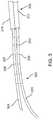
- FIG. 6Bis a perspective view of a distal portion of the ablation device of FIG. 6A .
- FIG. 6Cis a perspective view of a distal tip of the ablation device of FIG. 6A .
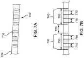
- FIG. 7Ais a side view of an ablation device including a set of electrodes, according to embodiments.
- FIG. 7Bis a side view of the set of electrodes of FIG. 7A with leads coupled thereto and disposed in the ablation device.
- FIG. 8is a block diagram of an electroporation system, according to embodiments.
- FIG. 9Ais a side view of a cinch device, according to embodiments.
- FIG. 9Bis a schematic cross-sectional side view of the cinch device of FIG. 9A .
- FIG. 9Cis a schematic side view of a distal end of the cinch device of FIG. 9A .
- FIG. 9Dis a schematic side view of a distal tip of the cinch device of FIG. 9A .
- FIG. 10is an example waveform including a sequence of voltage pulses with a pulse width defined for each pulse, according to embodiments.
- FIG. 11schematically illustrates a hierarchy of pulses including pulse widths, intervals between pulses, and groupings of pulses, according to embodiments.
- FIG. 12provides a schematic illustration of a nested hierarchy of monophasic pulses displaying different levels of nested hierarchy, according to embodiments.
- FIG. 13is a schematic illustration of a nested hierarchy of biphasic pulses displaying different levels of a nested hierarchy, according to embodiments.
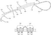
- FIG. 14is a perspective view of an ablation device according to embodiments, with the ablation device including multiple electrodes disposed along its shaft and wrapped around a portion of the pulmonary veins and being within the epicardial space of the heart in a subject body such that the ablation device forms an approximately closed contour around the pulmonary veins.
- FIG. 15is a perspective view of an ablation device and a cinch device including portions of the ablation device protruding from each end of the cinch device, according to embodiments.
- FIG. 16illustrates a method for positioning an ablation catheter relative to tissue of a patient, according to embodiments.
- FIG. 17illustrates a method for verifying ablation catheter positioning, according to embodiments.
- Described hereinare systems, devices, and methods for selective and rapid application of pulsed electric fields to ablate tissue by irreversible electroporation.
- the systems, devices, and methods described hereinmay be used to generate large electric field magnitudes at desired regions of interest and reduce peak electric field values elsewhere in order to reduce unintended tissue damage.
- the devices described hereininclude flexible catheters that may be placed for pulsed electric field ablation of cardiac tissue.
- an ablation devicemay be placed via subxiphoid access or by direct surgical placement into the pericardial space.
- Proper physical placement and tension applied between an ablation device (e.g., ablation catheter) and tissue to be ablatedmay ensure targeted and effective electroporation with reduced side effects and user error.
- a cinch device and fiducials disposed thereonmay be used to aid in positioning and verification of positioning of an ablation device relative to target tissue.
- An irreversible electroporation system as described hereinmay include a signal generator and a processor configured to apply one or more voltage pulse waveforms to a selected set of electrodes of an ablation device to deliver energy to a region of interest (e.g., ablation energy for tissue in a pulmonary vein ostium) and in one embodiment provide a highly configurable set of electrode channels (e.g., allow independent and arbitrary electrode selection).
- electrode pairingse.g., anode-cathode subsets
- the pulse waveforms disclosed hereinmay aid in therapeutic treatment of a variety of cardiac arrhythmias (e.g., atrial fibrillation).
- one or more electrodes of the ablation devicemay have an insulated electrical lead configured for sustaining a voltage potential of at least about 700 V without dielectric breakdown of its corresponding insulation.
- Subsets of electrodesmay be independently addressable such that the subset may be controlled (e.g., deliver energy) independently of any other electrode of the device. In this manner, the electrodes and/or electrode subsets may deliver different energy waveforms with different timing synergistically for electroporation of tissue.
- electroporationrefers to the application of an electric field to a cell membrane to change the permeability of the cell membrane to the extracellular environment.
- reversible electroporationrefers to the application of an electric field to a cell membrane to temporarily change the permeability of the cell membrane to the extracellular environment.
- a cell undergoing reversible electroporationcan observe the temporary and/or intermittent formation of one or more pores in its cell membrane that close up upon removal of the electric field.
- irreversible electroporationrefers to the application of an electric field to a cell membrane to permanently change the permeability of the cell membrane to the extracellular environment.
- a cell undergoing irreversible electroporationcan observe the formation of one or more pores in its cell membrane that persist upon removal of the electric field.
- Pulse waveforms for electroporation energy delivery as disclosed hereinmay enhance the safety, efficiency and effectiveness of energy delivery to tissue by reducing the electric field threshold associated with irreversible electroporation, thus yielding more effective ablative lesions with a reduction in total energy delivered.
- the voltage pulse waveforms disclosed hereinmay be hierarchical and have a nested structure.
- the pulse waveformmay include hierarchical groupings of pulses having associated timescales.
- the methods, systems, and devices disclosed hereinmay comprise one or more of the methods, systems, and devices described in International Application Serial No. PCT/US2016/057664, filed on Oct.
- the systemsmay further include a cardiac stimulator used to synchronize the generation of the pulse waveform to a paced heartbeat.
- the cardiac stimulatormay electrically pace the heart with a cardiac stimulator and ensure pacing capture to establish periodicity and predictability of the cardiac cycle.
- a time window within a refractory period of the periodic cardiac cyclemay be selected for voltage pulse waveform delivery.
- voltage pulse waveformsmay be delivered in the refractory period of the cardiac cycle so as to avoid disruption of the sinus rhythm of the heart.
- the systemmay optionally include one or more return electrodes.
- cardiac stimulator functionalitymay be integrated into a signal generator (e.g., ablation console, waveform generator console).
- one or more cathetersmay be advanced to a target location.
- the electrodes through which the voltage pulse waveform is deliveredmay be disposed on an epicardial device.
- the methods described heremay include introducing an ablation catheter through a first lumen of a cinch device.
- the ablation cathetermay be advanced out of the first lumen and looped around cardiac tissue such as a set of pulmonary veins.
- the distal end of the ablation cathetermay be advanced back into the cinch device through a distal end of a second lumen.
- the ablation cathetermay then be advanced out of the proximal end of the cinch device such that the proximal and distal ends of the ablation catheter are on the proximal side of the ablation catheter.
- the ends of the ablation cathetermay be pulled away from the cinch device held in place such that the loop of the ablation catheter tightens around the tissue to increase contact and apply a predetermined force.
- a position of the ablation catheter relative to the cinch devicemay be verified using a set of fiducials disposed on the ablation catheter and/or cinch device.
- one or more electrodes and/or one or more subsets of electrodesmay be disposed within a lumen of the cinch device. These electrodes may be non-activated for ablation.
- a pulse waveformmay be generated and delivered to one or more identified electrodes of the ablation catheter (e.g., electrodes uncovered by the cinch device) to ablate tissue.
- the pulse waveformmay be generated in synchronization with a pacing signal of the heart to avoid disruption of the sinus rhythm of the heart.
- the electrodesmay be configured in anode-cathode subsets.
- the pulse waveformmay include hierarchical waveforms to aid in tissue ablation and reduce damage to healthy tissue.
- a pulmonary vein isolation (PV isolation) systemmay include an ablation device ( 15 ) (e.g., ablation catheter), having a proximal portion ( 9 ) and a distal portion ( 8 ).
- ablation devicee.g., ablation catheter
- the ablation device ( 15 )may include a set of electrodes ( 17 ) disposed along its length, and where the ablation device ( 15 ) is wrapped in the epicardial space around all four pulmonary veins ( 10 , 11 , 12 , 13 ) of a heart ( 7 ) in a subject or patient anatomy, with the proximal and distal portions ( 9 ) and ( 8 ) respectively of the ablation device ( 15 ) extending out and away to eventually emerge from the patient's chest.
- the ablation device ( 15 ) and any of the ablation devices described hereincan be similar to the ablation catheters described in PCT Publication No.
- the ablation device ( 15 )may be disposed about the pulmonary veins ( 10 , 11 , 12 , 13 ) using any suitable procedure and apparatus.
- the ablation devicesmay be disposed about the pulmonary veins ( 10 , 11 , 12 , 13 ) and/or the heart ( 7 ) using a puncturing apparatus disposed via a subxiphoid pericardial access location and using guidewire-based delivery methods as described in the '394 PCT Application Publication and/or International Application Serial No. PCT/US2017/037609, filed on Jun. 15, 2017, which is incorporated herein by reference in its entirety.
- delivery cathetershaving magnetic members configured to form a magnetic coupling across a pericardial reflection can be used to deliver a guidewire into position around a heart.
- An alternative placement methodincludes direct surgical placement in an open chest, such as during a surgical procedure.
- ends ( 8 ) and ( 9 ) of the ablation device ( 15 )can be cinched together using a cinch device, as described in more detail herein, to effectively hold the ablation devices in place or in stable position relative to each other.
- the ablation device ( 15 )may be inserted into one end of a proximal end of a first lumen of a double-barreled cinch device, as described in detail herein, then pulled through the lumen, placed around the base of one or more pulmonary veins to form a loop around the pulmonary veins, and then inserted into a distal end of a second lumen of the cinch device such that a distal end of the ablation device ( 15 ) extends from the proximal end of the second lumen of the cinch device.
- FIG. 14illustrates a single catheter system
- the embodiments described hereinmay also apply to a two catheter system encircling the pulmonary veins such as described in International Application No. PCT/US2015/031086, entitled “METHODS AND APPARATUS FOR MULTI-CATHETER TISSUE ABLATION,” filed on May 15, 2015, which is incorporated herein by reference in its entirety.
- a voltage (e.g., DC voltage) for electroporationmay be applied to subsets of electrodes identified as anodes and cathodes respectively on the two devices on approximately opposite sides of the closed contour defined by the shapes of the ablation device ( 15 ) around the pulmonary veins.
- the voltagemay be applied in brief pulses sufficient to cause irreversible electroporation and may be in the range of 0.5 kV to 10 kV and more preferably in the range 1 kV to 2.5 kV, so that a threshold electric field value of around 200 Volts/cm may be effectively achieved in the cardiac tissue to be ablated.
- the active electrodes on the two devicesmay be automatically and/or manually identified on an X-ray or fluoroscopic image obtained at an appropriate angulation that permits identification of the geometric distance between anode and cathode electrodes, or their respective centroids.
- fiducialsmay be disposed on surfaces of one or more of the ablation device ( 15 ) and cinch device and may be configured to be visualized fluoroscopically to aid identification of electrode locations relative to the cinch device. Accordingly, a position of the ablation device ( 15 ) relative to the cinch device may be verified.
- the signal generatormay be configured to deliver a voltage only to the subset of electrodes that are uncovered by the cinch device to deliver ablation energy to tissue.
- the voltage generator setting for irreversible electroporationmay be automatically identified by the electroporation system based on this distance measure corresponding to electrode location.
- the voltage valuemay be selected directly by a user from a suitable dial, slider, touch screen, or any other user interface.
- the voltage pulsemay result in a current flowing between the anode and cathode electrodes on opposite sides of the contour defined by the conjoint shapes of the two devices, with current flowing through the cardiac wall tissue and through the intervening blood in the cardiac chamber, with the current entering the cardiac tissue from the anode electrodes and returning back through the cathode electrodes.
- the forward and return current paths (leads)may be respectively disposed inside distinct devices and/or the same device.
- all active electrodes on a given devicemay be of like polarity.
- electrodes on a single devicecan be activated as anode-cathode sets. Areas of cardiac wall tissue where the electric field is sufficiently large for irreversible electroporation may be ablated during the voltage pulse application.
- the pulse waveformmay be generated in synchronization with a pacing signal of the heart to avoid disruption of the sinus rhythm of the heart.
- the electrodesmay be configured in anode-cathode (e.g., bipole) subsets.
- the pulse waveformmay include hierarchical waveforms to aid in tissue ablation and reduce damage to healthy tissue, as described in International Application Serial No. PCT/US2016/057664, as incorporated by reference herein.
- electroporationrefers to the application of an electric field to a cell membrane to change the permeability of the cell membrane to the extracellular environment.
- reversible electroporationrefers to the application of an electric field to a cell membrane to temporarily change the permeability of the cell membrane to the extracellular environment.
- a cell undergoing reversible electroporationcan observe the temporary and/or intermittent formation of one or more pores in its cell membrane that close up upon removal of the electric field.
- irreversible electroporationrefers to the application of an electric field to a cell membrane to permanently change the permeability of the cell membrane to the extracellular environment.
- a cell undergoing irreversible electroporationcan observe the formation of one or more pores in its cell membrane that persist upon removal of the electric field.
- Pulse waveforms for electroporation energy delivery as disclosed hereinmay enhance the safety, efficiency, and effectiveness of energy delivery to tissue by reducing the electric field threshold associated with irreversible electroporation, thus yielding more effective ablative lesions with a reduction in total energy delivered.
- the methods described heremay include placing tissue (e.g., pulmonary vein) in contact with the electrodes.
- a pulse waveformmay be generated and delivered to one or more electrodes of the device to ablate tissue.
- the pulse waveformmay be generated in synchronization with a pacing signal of the heart to avoid disruption of the sinus rhythm of the heart.
- the electrodesmay be configured in anode-cathode (e.g., bipole) subsets.
- the pulse waveformmay include hierarchical waveforms to aid in tissue ablation and reduce damage to healthy tissue.
- a system for ablating tissue described heremay include a signal generator and an ablation device having one or more electrodes for the selective and rapid application of DC voltage to drive electroporation.
- the systems and devices described hereininclude one or more ablation devices configured to ablate tissue of the heart. Voltages may be applied to a selected subset of the electrodes, with independent subset selections for anode and cathode electrode selections.
- the ablation devicemay be coupled to one or more electrode channels of the signal generator.
- Each electrode channel, or subset of electrode channelsmay be independently configured as an anode or cathode and a voltage pulse waveform may be delivered through one or more of the electrode channels in a predetermined sequence.
- a pacing signal for cardiac stimulationmay be generated and used to generate the pulse waveform by the signal generator in synchronization with the pacing signal.
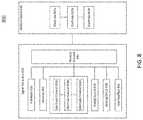
- FIG. 8schematically illustrates an ablation system ( 800 ) configured to deliver voltage pulse waveforms for tissue ablation.
- the system ( 800 )may include a signal generator ( 810 ) and ablation device ( 840 ).
- the signal generator ( 810 )may be coupled to at least one ablation device ( 840 ) having a set of one or more electrodes ( 842 a , 842 b , . . . , 842 n ).
- the signal generator ( 810 )may be configured to generate pulse waveforms for irreversible electroporation of tissue, such as, for example, heart tissue.
- the signal generator ( 810 )may be a voltage pulse waveform generator and deliver a pulse waveform to a set of electrodes ( 842 a , 842 b , . . . , 842 n ) of the ablation device ( 840 ).
- the signal generator ( 810 )may generate and deliver several types of signals including, but not limited to, radiofrequency (RF), direct current (DC) impulses (such as high-voltage, ultra-short pulses used in electroporation), stimulus range impulses, and/or hybrid electrical impulses.
- RFradiofrequency
- DCdirect current
- stimulus range impulsessuch as high-voltage, ultra-short pulses used in electroporation
- hybrid electrical impulsessuch as high-voltage, ultra-short pulses used in electroporation
- the signal generator ( 810 )may generate monophasic (DC) pulses and biphasic (DC and AC) pulses.
- the signal generator ( 810 )may include a processor ( 820 ), memory ( 822 ), a set of electrode channels ( 824 a , 824 b , . . . , 824 n ), energy source ( 826 ), sensing circuit ( 828 ), routing console ( 830 ), and user interface ( 832 ).
- One or more signal generator componentsmay be coupled using a communication bus.
- the processor ( 820 )may incorporate data received from one or more of memory ( 822 ), electrode channels ( 824 a , 824 b , . . .
- the memory ( 822 )may further store instructions to cause the processor ( 820 ) to execute modules, processes and/or functions associated with the system ( 800 ), such as pulse waveform generation and delivery, and/or electrode channel configuration.
- the memory ( 822 )may be configured to store anode/cathode configuration data, electrode channel configuration data, pulse waveform data, fault data, energy discharge data, heart pacing data, patient data, clinical data, procedure data, sensor data, temperature data, and/or the like.
- the ablation device ( 840 )may include a device configured to receive and/or deliver the pulse waveforms described herein.
- the ablation device ( 840 )may be introduced around a pulmonary vein and positioned to align one or more electrodes ( 842 a , 842 b , . . . , 842 n ) to heart tissue, and then deliver the pulse waveforms to ablate tissue.
- the ablation device ( 840 )may include one or more electrodes ( 842 a , 842 b , . . .
- the electrodes ( 842 a , 842 b , . . . , 842 n )may be grouped into one or more anode-cathode subsets such as, for example, a subset including one anode and one cathode, a subset including two anodes and two cathodes, a subset including two anodes and one cathode, a subset including one anode and two cathodes, a subset including three anodes and one cathode, a subset including three anodes and two cathodes, and/or the like.
- the set of electrodesmay include any number of electrodes, for example, 2, 3, 4, 5, 6, 7, 8, 9, 10, 12, or more electrodes.
- predetermined subsets of electrodesmay be electrically wired together so that each such subset is independently addressable.
- the methods, systems, and devices disclosed hereinmay include one or more of the methods, systems, and devices described in U.S. patent application Ser. No. 15/499,804, filed on Apr. 27, 2017, and titled “SYSTEMS, DEVICES, AND METHODS FOR SIGNAL GENERATION”; International Application Serial No. PCT/US17/12099, filed on Jan.
- the processor ( 820 )may be any suitable processing device configured to run and/or execute a set of instructions or code and may include one or more data processors, image processors, graphics processing units, physics processing units, digital signal processors, and/or central processing units.
- the processor ( 820 )may be, for example, a general purpose processor, Field Programmable Gate Array (FPGA), an Application Specific Integrated Circuit (ASIC), and/or the like.
- the processor ( 820 )may be configured to run and/or execute application processes and/or other modules, processes and/or functions associated with the system and/or a network associated therewith (not shown).
- the processormay include both a microcontroller unit and an FPGA unit, with the microcontroller sending electrode sequence instructions to the FPGA.
- the underlying device technologiesmay be provided in a variety of component types, e.g., metal-oxide semiconductor field-effect transistor (MOSFET) technologies like complementary metal-oxide semiconductor (CMOS), bipolar technologies like emitter-coupled logic (ECL), polymer technologies (e.g., silicon-conjugated polymer and metal-conjugated polymer-metal structures), mixed analog and digital, and/or the like.
- MOSFETmetal-oxide semiconductor field-effect transistor
- CMOScomplementary metal-oxide semiconductor
- bipolar technologieslike emitter-coupled logic (ECL)
- polymer technologiese.g., silicon-conjugated polymer and metal-conjugated polymer-metal structures
- mixed analog and digitaland/or the like.
- the memory ( 822 )may include a database (not shown) and may be, for example, a random access memory (RAM), a memory buffer, a hard drive, an erasable programmable read-only memory (EPROM), an electrically erasable read-only memory (EEPROM), a read-only memory (ROM), Flash memory, etc.
- the memory ( 822 )may store instructions to cause the processor ( 820 ) to execute modules, processes and/or functions associated with the system ( 800 ), such as pulse waveform generation and/or electrode channel configuration.
- a set of electrode channels ( 824 a , 824 b , . . . , 824 n )may include a set of active solid-state switches.
- the set of electrode channels ( 824 a , 824 b , . . . , 824 n )may be configured in a number of ways, including independent anode/cathode configuration for each electrode channel.
- the set of electrode channels ( 824 a , 824 b , . . . , 824 n )may include any number of channels, for example, 2, 3, 4, 5, 6, 7, 8, 9, 10, 12, or more electrode channels.
- Energy deliverymay use any combination of electrode channels ( 824 a , 824 b , . . . , 824 n ) and any order for an energy delivery sequence.
- the energy deliveredmay be an RF and/or any tissue ablation energy.
- the set of electrode channels ( 824 a , 824 b , . . . , 824 n )may be coupled to a routing console ( 830 ) to deliver energy to a set of electrodes ( 842 ) coupled to the routing console ( 830 ).
- the set of electrode channels ( 824 a , 824 b , . . . , 824 n )may be coupled to an energy source ( 826 ) to receive energy (e.g., a pulse waveform).
- Processor ( 820 )may be coupled to each electrode channel ( 824 a , 824 b , . . .
- each electrode channel ( 824 a , 824 b , . . . , 824 n )may include an electronic switch (e.g., bipolar transistor) and a drive circuit, as described in detail herein.
- each electrode channel ( 824 a , 824 b , . . . , 824 n )may have a bootstrap configuration for low and high frequency operation.
- the pulse duration of voltage pulses delivered through an electrode channelmay be in the range of between about 1 microsecond and about 1000 microseconds. In biphasic mode, this corresponds to an approximate frequency range of between about 500 Hz and about 500 KHz for the frequency associated with the voltage pulses.
- a controllerincluding the processor ( 820 ) and memory ( 822 ) may be coupled to each electrode of the set of electrodes ( 842 ).
- the controllermay be configured to generate a pulse waveform and configure the set of electrodes ( 842 ) for pulse waveform delivery.
- the pulse waveformmay be delivered to the set of electrodes ( 842 ).
- an energy source ( 826 )may be configured to convert and supply energy to a set of electrodes ( 842 ) coupled to the signal generator ( 810 ).
- the energy source ( 826 ) of the signal generator ( 810 )may include a DC power supply and be configured as an AC/DC switcher.
- an energy source ( 826 ) of the signal generator ( 810 )may deliver rectangular-wave pulses with a peak maximum voltage of up to about 7 kV into a device with an impedance in the range of between about 30 ⁇ and about 3000 ⁇ with a pulse width in the range between about 1 microsecond and about 500 microseconds, including all values and subranges in between.
- the energy source ( 826 )may be configured to store energy.
- the energy source ( 826 )may include one or more capacitors to store energy from a power supply. While these examples are included for purely non-limiting illustrative purposes, it is noted that a variety of pulse waveforms with a range of pulse durations, intervals between pulses, pulse groupings, etc. may be generated depending on the clinical application.
- a sensing circuit ( 828 )may be configured to determine an amount of current being delivered to a device coupled to the signal generator ( 810 ) (e.g., electrode ( 842 ) coupled to the electrode channel ( 824 )). As described in more detail herein, the sensing circuit ( 828 ) may also be used to classify an electrode channel fault, monitor capacitor discharge, and/or sense arcing. In some embodiments, the sensing circuit ( 828 ) may be a direct current sensing circuit and/or a low-side sensing circuit. The sensing circuit may include one or more operational amplifiers, difference amplifiers (DA), instrumentation amplifiers (IA), and/or current shunt monitors (CSM).
- DAdifference amplifiers
- IAinstrumentation amplifiers
- CSMcurrent shunt monitors
- the routing console ( 830 )may be configured to electrically couple a set of electrodes ( 842 ) of an ablation device ( 840 ) to a set of electrode channels ( 824 a , 824 b , . . . , 824 n ).
- the routing console ( 830 )may be configured to selectively deliver energy to the set of electrodes ( 842 ) using the set of electrode channels ( 824 a , 824 b , . . . , 824 n ).
- One or more ablation devices ( 840 ) each having a set of electrodes ( 842 )may be coupled to the routing console ( 830 ).
- the set of electrodes ( 842 )may include any number of electrodes, for example, 1, 2, 3, 4, 5, 6, 7, 8, 9, 10, 12, or more electrodes.
- the electrode channels ( 824 a , 824 b , . . . , 824 n ) configured for energy deliverymay not be adjacent to each other but may be arbitrarily disposed along the ablation device ( 840 ).
- a multi-electrode ablation devicemay allow targeted and precise energy delivery to tissue.
- the electrodes ( 842 ) of an ablation device ( 840 )may be configured for energy delivery (e.g., as an anode/cathode pair of electrodes ( 842 ) and may be disposed on adjacent or any other relative locations along the ablation device ( 840 ).
- the signal generator ( 810 ) coupled to the ablation device ( 840 )may include a set of electrode channels ( 824 a , 824 b , . . . , 824 n ) having N electrode channels corresponding to M electrodes ( 842 n ) of the ablation device ( 840 ).
- Each electrode channel ( 824 a , 824 b , . . . , 824 n ) of the signal generator ( 810 )may be coupled to one of the electrodes ( 842 ) of the ablation device ( 840 ).
- Configurable electrode channel and electrode selectionmay provide flexibility in positioning the electrodes for ablating a desired region of interest, as described in more detail herein.
- the routing console ( 830 )may receive input from the processor ( 820 ) and/or user interface ( 832 ) for electrode channel selection and energy delivery to one or more electrodes ( 842 ).
- a user interface ( 832 )may be configured as a communication interface between an operator and the system ( 800 ).
- the user interface ( 832 )may include an input device and output device (e.g., touch surface and display).
- patient data from memory ( 822 )may be received by user interface ( 832 ) and output visually and/or audibly.
- Electric current data from sensing circuit ( 828 )may be received and output on a display of user interface ( 832 ).
- operator control of an input devicehaving one or more buttons, knobs, dials, switches, trackball, touch surface, and/or the like, may generate a control signal to the signal generator ( 810 ) and/or ablation device ( 840 ).
- an input device of the user interface ( 832 )may include a touch surface for operator input and may be configured to detect contact and movement on the touch surface using any of a plurality of touch sensitivity technologies including capacitive, resistive, infrared, optical imaging, dispersive signal, acoustic pulse recognition, and surface acoustic wave technologies. Additionally or alternatively, the user interface ( 832 ) may include a step switch or foot pedal.
- an output device of the user interface ( 832 )may include one or more of a display device and audio device.
- the display devicemay include at least one of a light emitting diode (LED), liquid crystal display (LCD), electroluminescent display (ELD), plasma display panel (PDP), thin film transistor (TFT), and organic light emitting diodes (OLED).
- An audio devicemay audibly output patient data, sensor data, system data, other data, alarms, warnings, and/or the like.
- the audio devicemay include at least one of a speaker, piezoelectric audio device, magnetostrictive speaker, and/or digital speaker. In one embodiment, the audio device may output an audible warning upon detection of a fault in the signal generator ( 810 ) and/or ablation device ( 840 ).
- the signal generator ( 810 )may be mounted on a trolley or cart.
- the user interface ( 832 )may be formed in the same or different housing as the signal generator ( 810 ).
- the user interface ( 832 )may be mounted to any suitable object, such as furniture (e.g., a bed rail), a wall, a ceiling, or may be self-standing.
- the input devicemay include a wired and/or wireless transmitter configured to transmit a control signal to a wired and/or wireless receiver of the signal generator ( 810 ).
- the systems described hereinmay include one or more sterile coverings configured to create a sterile barrier around portions of the system ( 800 ).
- the system ( 800 )may include one or more sterile coverings to form a sterile field.
- a sterile coveringmay be placed between the ablation device(s) and the patient, forming a barrier between an interior, non-sterile side including the patient, signal generator, and ablation devices and an exterior, sterile side including the operator.
- components of the system ( 800 )may be sterilizable.
- the sterile coveringmay include, for example, a sterile drape configured to cover at least a portion of a system component.
- a sterile covering(e.g., sterile drape) may be configured to create a sterile barrier with respect to a user interface ( 832 ) of the system ( 800 ).
- the sterile drapemay be clear and allow an operator to visualize and manually manipulate the user interface ( 832 ).
- the sterile coveringmay conform tightly around one or more system components or may drape loosely so as to allow components to be adjusted within the sterile field.
- the systems described heremay include one or more multi-electrode ablation devices (e.g., catheters) configured to ablate tissue for treating a heart condition and a cinch device configured to aid in positioning of the ablation device relative to the tissue.
- the ablation devicemay be configured to be positioned against tissue using a cinch device.
- the cinch devicemay include an elongate shaft defining a pair of parallel lumens.
- a distal end of the elongate shaftmay be curved to aid introduction of the ablation device into a pericardial space.
- the cinch devicemay include a set of fiducials configured for visualization (e.g., imaging by fluoroscopy, X-ray).
- An ablation device and cinch devicemay be configured for use in a cardiac procedure, such as, for example, creation of a box lesion around the pulmonary veins in the epicardial or pericardial space.
- the ablation devicesmay include a set of metallic electrodes.
- the electrodesmay also be generally atraumatic so as to decrease the risk of damage to tissue through laceration and puncture.
- the edges of the electrodesmay be rounded to reduce tissue damage and to increase the uniformity of the electric field generated at a central portion and a peripheral portion of the electrodes.
- one or more electrodes of the ablation devicemay have an insulated electrical lead configured for sustaining a voltage potential of at least about 700 V without dielectric breakdown of its corresponding insulation.
- the insulation on each of the electrical leadsmay sustain an electrical potential difference of between about 200 V and about 3,000 V across its thickness without dielectric breakdown, including all values and sub-ranges in between.
- the electrodesmay be independently addressable such that each electrode may be controlled (e.g., deliver energy) independently of any other electrode of the ablation device.
- the electrodesmay, for example, be connected to an insulated electrical lead coupled to a signal generator to receive pulse waveforms as described herein.
- FIG. 1is a perspective view of an ablation device ( 102 ) and cinch device ( 130 ).
- the cinch device ( 130 )may have a double-barrel configuration sized to allow the ablation device to pass through it.
- the ablation device ( 102 )may be looped around a set of pulmonary veins (not shown in FIG. 1 ) and through the cinch device ( 130 ) such that the proximal and distal ends of the ablation device ( 102 ) may be disposed outside the body and generally adjacent to each other. That is, the ends of the ablation device ( 102 ) may be disposed proximal to the cinch device ( 130 ).
- the cinch device ( 130 )may then be manipulated to tighten the loop formed by the ablation device ( 102 ) around the pulmonary veins to aid positioning of the ablation device for tissue ablation.
- the ablation device ( 102 )may include a handle ( 104 ) coupled to a proximal portion of the ablation device ( 102 ) and a distal tip ( 101 ).
- the distal tip ( 101 )may include an atraumatic shape to reduce trauma to tissue.
- the ablation device ( 102 )may be configured to be slidably disposed within a first lumen ( 106 ) and a second lumen ( 131 ) of the cinch device ( 130 ).
- the first and second lumens ( 106 , 131 )may correspond to respective hollow tubular structures (e.g., first cinch catheter, second cinch catheter) that may be joined together along their length (L) to form a double-barreled or double lumen structure.
- the cinch device ( 130 )may define a longitudinal axis.
- the ablation device ( 102 )can include a series of fiducials or markings at its proximal and distal ends.
- a series of markings ( 112 , 114 )can be disposed on a distal section of the ablation device ( 102 ), and a series of markings ( 144 , 146 ) can be disposed on a proximal section of the ablation device ( 102 ).
- these series of markingscan be used to determine the electrodes (e.g., electrodes ( 108 )) that are disposed inside or outside of the cinch device ( 130 ), as described in further detail with reference to FIGS. 2-5 .
- the spacing between markings ( 112 , 114 )can be set to correspond to a length of a group of electrodes and/or a distance between groups of electrodes.
- the length (L) of the cinch device ( 130 )can be a multiple of such length and/or distance, to further facilitate determination of a number of electrodes or groups of electrodes inside or outside of the cinch device ( 130 ).
- the cinch device ( 130 )may be sized and shaped for subxiphoid access.
- the cinch device ( 130 )may include a curved distal portion, as described herein with respect to FIGS. 9A-9D .
- the ablation device ( 102 )may have a diameter smaller than a diameter of the cinch device ( 130 ).
- the ablation device ( 102 )may be introduced into a proximal end of first lumen ( 106 ) of the cinch device ( 130 ).
- the ablation device ( 102 )may extend from a distal end of the first lumen ( 106 ) and be configured to form a loop.
- the ablation device ( 102 )may include a central portion ( 124 ) having high flexibility (e.g., a flexible curvature).
- the ablation device ( 102 )may then be introduced into a distal end of second lumen ( 131 ).
- the ablation device ( 102 )may extend from a proximal end of the second lumen ( 131 ) such that the distal tip ( 101 ) of the ablation device ( 102 ) may be advanced out of the proximal end of the second lumen ( 131 ).
- the cinch device ( 130 )may be sized to ensure that a suitable number of the electrodes ( 108 ) on the ablation device ( 102 ) may be drawn or pulled into each lumen ( 106 , 131 ) of the cinch device ( 130 ). Further, a desired length of the ablation device ( 102 ) may extend from a proximal end of the cinch device ( 130 ) for manipulation when the ablation device ( 102 ) forms a loop and is advanced through the cinch device ( 130 ). For example, the cinch device ( 130 ) may have a length in the range between about 6 cm and about 30 cm, including all values and sub-ranges in-between. A distal portion of the ablation device (e.g., distal to the electrodes ( 108 )) may have a length in the range between about 20 cm and about 70 cm, including all values and sub-ranges in-between.
- the ablation device ( 102 )may include one or more electrodes ( 108 ) formed on a surface of the ablation device ( 102 ).
- a set of electrodes ( 108 )are disposed along a central portion ( 124 ) of the ablation device ( 102 ).
- each electrode ( 108 )may be independently addressable, while in other embodiments one or more subsets of electrodes ( 108 ) may be electrically wired together.
- a set of three or four adjacent electrodesmay be electrically wired together as an electrode subset.
- non-adjacent electrodesmay be electrically wired together.
- a spacing between successive electrodes and/or electrode subsetsmay vary.
- Each electrode ( 108 )may include or be attached to an insulated electrical lead configured to sustain a voltage potential of at least about 700 V without dielectric breakdown of its corresponding insulation. In cases where more than one electrode is electrically wired together as an electrode group, a single such insulated lead may be connected to the electrode group.
- the electrodes ( 108 )may have about the same size, shape, and/or spacing. In some embodiments, the size, shape, and spacing of the electrodes ( 108 ) may differ.
- the ablation device ( 102 )may be configured for delivering a set of voltage pulse waveforms using a set of electrodes ( 108 ) to ablate tissue and electrically isolate one or more regions of the heart. At least a portion of the ablation device ( 102 ) may include a flexible curvature. For example, a central portion ( 124 ) of the ablation device ( 102 ) disposed between a proximal portion and a distal portion of the ablation device ( 102 ) may be flexible and configured to conform to a cardiac anatomy.
- the ablation device ( 102 )may be configured to transform between a first configuration where the ablation device ( 102 ) is partially advanced into the cinch device ( 130 ) and a second configuration where the central portion ( 124 ) of the ablation device ( 102 ) forms a loop that may be configured to encircle tissue such as a pulmonary vein firmly. In this manner, the ablation device ( 102 ) and cinch device ( 130 ) may increase contact with heart tissue.
- a handle ( 104 )may be coupled to the ablation device ( 102 ) to form a hub from which an electrical cable and/or connector (not shown) may be attached and for providing an entry point for guidewire introduction.
- the connectormay connect directly or through an extension cable to a signal generator for delivery of voltage waveforms for pulsed electric field ablation.
- the handle ( 104 )may include a guidewire lumen hub (not shown) for introduction of a guidewire that may provide mechanical support to the ablation device ( 102 ) when wrapped around tissue such as the pulmonary veins.
- the handlemay define a flush port configured for flushing a guidewire lumen to aid introduction of a guidewire.
- the cinch device ( 130 )may be positioned within the pericardial space at a location that allows access to the pulmonary veins for an ablation device ( 102 ) such as described herein.
- the ablation device ( 102 )may be advanced through a first lumen ( 106 ) and looped around a set of pulmonary veins (e.g., four pulmonary veins). For example, pericardial reflections or folds in the pericardial membrane may be excised to allow the ablation device ( 102 ) to encircle all four pulmonary veins at the base of the trunk of the veins.
- the ablation device ( 102 )may be advanced through the second lumen ( 131 ).
- the cinch device ( 130 )may be advanced towards the heart, angled obliquely relative to the patient's chest, and placed on a posterior side of the heart.
- the proximal and distal ends of the ablation device ( 102 )may be drawn through the cinch device ( 130 ) and pulled away from the heart to apply a predetermined amount of force to the pulmonary veins using the looped central portion ( 124 ) of the ablation device ( 102 ).
- the number of electrodes that may be drawn into the cinch device ( 130 ) when the ablation device ( 102 ) is tightened around the pulmonary veinsmay depend on the size of the left atrium and the amount of force applied. Any electrodes ( 108 ) disposed within a lumen of the cinch device ( 130 ) should not receive energy while the electrodes ( 108 ) looped around and in contact with the pulmonary veins. Electrodes ( 108 ) distal to a distal end of the cinch device ( 130 ) may be configured to receive ablation energy. Some embodiments described herein may provide a direct visual means to identify a location of a set of electrodes ( 108 ) of an ablation device ( 102 ) relative to the cinch device ( 130 ).
- FIG. 6Ais a side view of an example, non-limiting ablation device ( 602 ).
- the ablation device ( 602 )may include a catheter having a proximal portion ( 603 ), a central portion ( 624 ), and a distal portion ( 601 ).
- the proximal, distal, and central portions of themay each be composed of a compliant and/or flexible material to allow one or more portions of the ablation device ( 602 ) to easily conform to a cardiac anatomy.
- the distal portion ( 601 )may include an atraumatic distal tip ( 605 ) such as shown in FIGS. 6B and 6C .
- the central portion ( 624 )may include a set of electrodes ( 608 ) disposed on a surface of the ablation device ( 602 ).
- the set of electrodes ( 608 )may include a plurality of subsets with each subset having a first length. Each subset of electrodes may be spaced apart from an adjacent subset by a second length. The second length may be greater than the first length.
- FIG. 6Ashows the set of electrodes grouped into subsets of three electrodes each. Each electrode within a subset can have a third length. In some embodiments, one or more electrodes within a subset may have different lengths. For example, FIGS. 7A and 7B , described below, provide a more detailed view of subsets of three electrodes with varying lengths. Alternatively, each electrode within a subset may have the same length.
- a handle ( 604 )may be coupled to the proximal portion ( 603 ) of the ablation device ( 602 ).
- a set of lead wires ( 640 )may be coupled to the handle ( 604 ) and may be disposed within a lumen of the ablation device ( 602 ) to connect to the set of electrodes ( 608 ).
- FIGS. 7A and 7Bare side views of a set of electrodes ( 708 ) of an example ablation device ( 702 ).
- the set of electrodes ( 708 )may be disposed on a central portion ( 724 ) of the ablation device ( 702 ).
- one or more sets of the electrodes ( 708 )may not be used to deliver ablation energy such as when those electrodes are disposed within a lumen of a cinch device.
- the electrode subsets ( 730 , 740 )may have a first length ( 750 ) and may be separated by a second length ( 720 ).
- the electrodesmay be formed of platinum-iridium material.
- the set of electrodes ( 708 )may include a multiplicity of triplet subsets or groups where the electrodes (each in the form of rings) may have a third length in the range between about 1 mm and about 12 mm, including all values and sub-ranges in-between.
- Each electrode within a subset or group of electrodes ( 730 , 740 )may be separated by a fourth length ( 710 ).
- the number of electrode subsetsmay range between about 4 and about 20, including all values and sub-ranges in-between.
- FIG. 9Ais a side view of a cinch device ( 930 ).
- the cinch devicemay include a distal portion having a curved portion ( 920 ) and a distal tip ( 910 ).
- the curved portion ( 920 )may aid in positioning and advancement of an ablation device within a body cavity.
- FIG. 9Bis a cross-sectional side view of a cinch device ( 930 ) having a first lumen ( 940 ) and a second lumen ( 950 ).
- the lumens ( 940 , 950 )may have the same diameter. The diameter can be about a diameter of an ablation catheter (not depicted) or larger such that it is designed for use therewith.
- FIGC and 9Dare schematic side views of a distal end of a cinch device ( 930 ) including the curved portion ( 920 ) and distal tip ( 910 ).
- the cinch device ( 930 )may be formed of Pebax (e.g., Pebax 40D).
- the distal tip ( 910 )may have a length of between about 5 mm and about 25 mm, and may be composed of a material visible under fluoroscopy.
- the one or more portions of the cinch device ( 930 )(e.g., the entire surface of the cinch device ( 930 )) may be visible under fluoroscopy.
- the distal tip ( 910 )may be atraumatic to reduce trauma to tissue.
- the curved portion ( 920 )may have a curvature of between about 30 degrees and 60 degrees.
- the curved portion ( 920 )may have a curvature of about 45 degree.
- one or more of an ablation device and cinch devicemay include a set of fiducials that allow a surgeon and/or imaging system to determine a location of a set of electrodes of the ablation device relative to the cinch device.
- a set of markings disposed on one or more of a proximal portion and distal portion of the ablation devicemay correspond to the number of electrodes or electrode subsets within a lumen (e.g., inside) of the cinch device and/or the number of electrodes or electrode sets disposed outside of the cinch device.
- the electrodes or electrode subsets within the cinch devicemay be configured to be deactivated while the remaining electrodes or electrode sets that extend or that are exposed outside of the cinch device may be configured to deliver ablation energy to tissue such as a portion around a set of pulmonary veins of the heart.
- a fiducialcorresponds to a mark, symbol (e.g., number, letter), geometric shape, hole, recession, protrusion, texture, combinations thereof, and the like disposed along a length of one or more of an ablation device and cinch device.
- FIG. 2is a perspective view of an ablation device ( 202 ) and cinch device ( 230 ) where a proximal portion ( 203 ) of the ablation device ( 202 ) may be extended through a proximal end of a first lumen ( 219 ) of the cinch device ( 230 ). A distal portion ( 201 ) of the ablation device ( 202 ) may be extended through a proximal end of a second lumen ( 210 ) of the cinch device ( 230 ).
- the proximal portion ( 203 )may include on its surface a first set of proximal fiducials ( 212 ) and a second set of proximal fiducials ( 214 ) disposed along its length.
- the first set of proximal fiducials ( 212 )may be different (e.g., larger, wider) than the second set of proximal fiducials ( 214 ).
- Fiducials of the first and second set of proximal fiducials ( 212 , 214 )may be alternately disposed along a length of the ablation device ( 202 ).
- Adjacent fiducials of the first and second set of proximal fiducials ( 212 , 214 )may be spaced apart by a length of an electrode of the ablation device ( 202 ) (not shown in FIG. 2 ).
- the distal portion ( 201 )may include on its surface a first set of distal fiducials ( 205 ) and a second set of distal fiducials ( 207 ) disposed along its length.
- the first set of distal fiducials ( 205 )may be larger than the second set of distal fiducials ( 207 ).
- Fiducials of the first and second set of distal fiducials ( 205 , 207 )may be alternately disposed along a length of the ablation device ( 202 ). Adjacent fiducials of the first and second set of distal fiducials ( 205 , 207 ) may be spaced apart by a length of an electrode. In some embodiments, the first and second sets of fiducials ( 205 , 207 , 212 , 214 ) may be identified and differentiated by number, location, length, thickness, width, depth, shape, color, orientation, texture, material, combinations thereof, and the like.
- each subset of electrodes of the ablation device ( 202 )may have a first length
- the length of the cinch device ( 230 )may be an integer multiple of the sum of the first length and the distance between successive electrode groups (second length).
- the shorter markingsmay be adjacent to the larger markings with a spacing equal to a length of one electrode (e.g., length of the smallest electrode in each electrode subset, or a fifth length).
- the sets of fiducials disposed proximal to the cinch device ( 230 )allow a surgeon to determine the number of electrodes disposed within the lumens of the cinch device ( 230 ) based on the number of sets of fiducials disposed proximal to the cinch device ( 230 ) (e.g., via visual confirmation, tactile confirmation, etc.).
- two electrode subsetsmay be disposed within the second lumen ( 210 ) (e.g., depending on a length of the second lumen ( 210 )), and the majority of electrodes of a third electrode subset may be disposed distal to the cinch device ( 230 ) and exposed for delivery of ablation energy.
- the number of electrode subsets disposed within the lumens of the cinch device ( 230 ) and the number of electrode subsets disposed distal to and exposed outside of the lumens of the cinch device ( 230 )can depend on, for example, a length of the lumens of the cinch device ( 230 ), a total number of electrode subsets, etc.
- FIG. 15depicts a distal portion ( 1501 ) of an ablation device ( 1502 ) in a lumen ( 1503 ) (e.g., lumen, barrel) of a cinch device ( 1530 ).
- a lumen1503
- a cinch device1530
- First and second sets of fiducials1505 , 1507 , 1511 , 1513 , 1515 , 1517 , 1519 , 1520 ) having longer and shorter markings respectively, are shown distributed along a distal portion ( 1501 ) of the ablation device ( 1502 ).
- the other three fiducial pairsare disposed inside the lumen ( 1503 ).
- a distal-most electrode subset of the ablation device ( 1502 )may include a triplet of electrodes ( 1525 , 1526 , 1527 ). As depicted in FIG. 15 , a distal end ( 1522 ) and a proximal end ( 1523 ) of the distal-most electrode ( 1525 ) of the triplet are disposed within the lumen ( 1503 ) such that electrodes ( 1526 , 1527 ) are exposed and distal to the lumen ( 1503 ) and may be configured for ablation energy delivery.
- the length of the lumen ( 1503 )may be four times the spacing between the distal ends of successive electrode triplets (e.g., sum of a first length and a second length).
- This spacing ris the sum of the length p (first length) of an electrode triplet and the gap d (second length) between adjacent electrode triplets.
- the spacing between successive fiducial pairs(for example, the distance between larger fiducial ( 1511 ) and larger fiducial ( 1515 )) may be configured as equal to the distance r between distal ends of successive electrode triplets.
- the lumenhas a length that may be an integer multiple of the distance r (i.e., the distance between the distal ends of successive fiducials).
- fiducials ( 1505 , 1507 ) exposed proximal to the lumen ( 1503 )may visually confirm that a single electrode (in this example, the distal-most electrode ( 1525 )) of the distal-most electrode triplet is disposed within the lumen ( 1503 ), while the rest of the electrodes ( 1526 , 1527 ) of that electrode triplet are exposed distal to the lumen ( 1503 ).
- fiducial configurationsmay enable other estimations.
- sets of fiducialsmay be used, with each fiducial set to replicate, represent, and/or otherwise correspond an electrode group (e.g., the electrode triplet in the above example).
- the number of electrodes disposed within the lumen of a cinch device tube, as well as which electrodes of the most distal-most exposed electrode group are disposed within the lumen of the cinch devicemay be visually confirmed, since a corresponding number of fiducial sets would be visible on the distal portion of the ablation proximal to the cinch device.
- a single fiducialmay be separated successively by a length (e.g., distance r) corresponding to the distance between distal ends of successive electrode groups.
- the number of fiducials visible on the distal portion of an ablation device outside the cinch devicemay correspond to the number of electrode groups that are disposed within a lumen of the cinch device.
- each electrode within a groupcan have the same length (e.g., as depicted in FIG. 15 ), while in other embodiments, electrodes within a group can have different lengths (e.g., as depicted in FIGS. 7A and 7B ).
- FIG. 3is a perspective view of an ablation device ( 302 ) and cinch device ( 330 ) where a proximal portion ( 303 ) of the ablation device ( 302 ) may be extended through a proximal end of a first lumen ( 317 ) of the cinch device ( 330 ).
- a distal portion ( 301 ) of the ablation device ( 302 )may be extended through a proximal end of a second lumen ( 315 ) of the cinch device ( 330 ).
- the proximal portion ( 303 )may include on its surface a set of proximal fiducials ( 309 , 313 ) (e.g., markings) disposed along its length.
- the distal portion ( 301 )may include on its surface a set of distal fiducials ( 305 , 307 ) (e.g., markings) disposed along its length.
- the proximal and distal set of fiducialsmay be identified and differentiated by one or more characteristics including number, location, length, thickness, width, depth, spacing, shape, color, pattern, orientation, texture, material, combinations thereof, and the like.
- each subset of electrodes of the ablation device ( 302 )may have the same length, and the length of the cinch device ( 330 ) may be an integer multiple of the sum of the electrode subset length and the distance between successive electrode groups.
- the set of fiducials disposed proximal to the cinch device ( 330 )allow a surgeon to determine the number of electrodes disposed within the lumens of the cinch device ( 330 ) based on the number of fiducials disposed proximal to the cinch device ( 330 ) determined based on visual confirmation, tactile confirmation, and/or other types of confirmation. For example, if four complete fiducials disposed along the distal portion ( 301 ) of the ablation device ( 302 ) are visible outside the cinch device ( 330 ), then three electrode subsets may be disposed within the second lumen ( 315 ) of the cinch device ( 330 ).
- a fourth electrode groupmay be determined to be either inside the cinch device ( 330 ) or exposed outside the cinch device ( 330 ), respectively.
- the number of electrode subsets disposed within the first lumen ( 317 ) of the cinch device ( 330 )may be determined using the exposed fiducials (e.g., visual, tactile, etc.) disposed along the length of the proximal portion ( 303 ) of the ablation device ( 302 ) proximal to the cinch device ( 302 ).
- two electrode subsetsmay be determined to be disposed within the first lumen ( 317 ) of the cinch device ( 330 ) based on the number of visible fiducials along the proximal portion ( 303 ).
- a signal generatormay be configured to deliver energy to electrodes that are looped around the pulmonary veins (and therefore exposed) without delivering energy to electrodes within the cinch device ( 330 ). For example, a user may enter fiducial information into a user interface of the signal generator.
- FIG. 4is a perspective view of an ablation device ( 402 ) and cinch device ( 430 ) where a proximal portion ( 403 ) of the ablation device ( 402 ) may be extended through a proximal end of a first lumen ( 417 ) of the cinch device ( 430 ).
- the ablation device ( 402 )can be similar to other ablation devices described herein, but have fiducials implemented as alternating dark and light bands.
- a distal portion ( 401 ) of the ablation device ( 402 )may be extended through a proximal end of a second lumen ( 415 ) of the cinch device ( 430 ).
- the proximal portion ( 403 )may include on its surface a set of proximal fiducials ( 409 , 410 ) (e.g., alternating dark and light bands) disposed along its length.
- the distal portion ( 401 )may include on its surface a set of distal fiducials ( 405 , 406 ) (e.g., alternating dark and light bands) disposed along its length.
- the proximal and distal set of fiducialsmay be identified and differentiated by number, location, length, thickness, spacing, width, depth, shape, color, pattern, orientation, texture, combinations thereof, and the like.
- each subset of electrodes of the ablation device ( 402 )may have the same length, and the length of the cinch device may be an integer multiple of the sum of the electrode subset length and the distance between successive electrode groups.
- the set of fiducials disposed outside the cinch device ( 430 )allow a surgeon to determine the number of electrodes disposed within the lumens of the cinch device ( 430 ) based on the number of fiducials disposed outside the cinch device ( 430 ) that can be determined using visual, tactile, etc. confirmation. For example, if four complete sets of bands disposed along the distal portion ( 401 ) of the ablation device ( 402 ) are visible proximal to the cinch device ( 430 ), then at least three electrode subsets may be disposed within the second lumen ( 415 ) of the cinch device ( 430 ).
- a fourth electrode groupmay be determined to be either inside the cinch device ( 430 ) or exposed outside the cinch device ( 430 ), respectively.
- the number of electrode subsets disposed within the first lumen ( 417 ) of the cinch device ( 430 )may be determined using the visible fiducials disposed along the length of the proximal portion ( 403 ) of the ablation device ( 402 ) proximal to the cinch device ( 402 ). For example, two electrode subsets may be determined to be disposed within the first lumen ( 417 ) of the cinch device ( 430 ) based on the number of visible fiducials along the proximal portion ( 403 ).
- a signal generatormay be configured to deliver energy to the exposed electrodes looped around the pulmonary veins without delivering energy to electrodes within the cinch device ( 430 ). For example, a user may enter fiducial information into a user interface of the signal generator.
- FIG. 5is a perspective view of a cinch device ( 530 ) including a first lumen ( 501 ) (e.g., proximal tube) and a second lumen ( 500 ) (e.g., distal tube).
- the first and second lumens ( 501 , 500 )may include on its surface a set of fiducials ( 503 , 505 , 507 , 512 , 513 ) disposed along its length adjacent to a proximal end ( 510 ) of the cinch device ( 530 ).
- the set of fiducialsmay be identified and differentiated by number, location, length, thickness, width, depth, shape, color, pattern, orientation, texture, material, combinations thereof, and the like.
- a distance from the proximal end ( 510 ) of the cinch device ( 530 ) to the first fiducial ( 503 )may be equal to a length of the first electrode of an electrode subset (e.g., three electrodes) of an ablation device.
- a distance from the first fiducial ( 503 ) to the second fiducial ( 505 )may correspond to a distance or separation between the first and second electrodes of the electrode subset of three electrodes.
- a distance between the second fiducial ( 505 ) and a third fiducial ( 507 )may correspond to a length of the second electrode of the electrode subset of three electrodes.
- a distance from third fiducial ( 507 ) to fourth fiducial ( 512 )may correspond to a distance or separation between the second electrode and the third electrode of an electrode subset of three electrodes.
- a distance from fourth fiducial ( 512 ) to fifth fiducial ( 513 )may be equal to a length of the third electrode of an electrode subset of three electrodes.
- the set of fiducials on each lumen of the cinch device ( 530 )may correspond to an electrode triplet of an ablation device configured to extend through the cinch device ( 530 ).
- an ablation device and cinch device each having fiducialsmay be used to improve determination of a location of the electrodes relative to each lumen of the cinch device.
- the fiducialsmay be used to determine the fraction of an electrode subset disposed outside the cinch device for each lumen of the cinch device.
- such fiducials on the cinch devicemay be provided in conjunction with fiducials on the ablation device in the form of alternating bands as illustrated in FIG. 4 to assist with such a determination of the exposed fraction of electrode subsets outside of the cinch device.
- a signal generatormay be configured to deliver energy to the electrodes looped around the pulmonary veins without delivering energy to electrodes within the cinch device. For example, a user may enter fiducial information into a user interface of the signal generator.
- the ablation device's position relative to the cinch devicemay be locked in place.
- the ablation devicemay be held in place relative to the cinch device using a locking mechanism.
- the ablation devicemay be held in place using a clip (e.g., a surgical clip) at a proximal end of the cinch device, surgical tape, combinations thereof, and the like.
- a locking mechanismmay be engaged after a predetermined number of electrodes of an electrode group are disposed distal to a cinch device (e.g., majority of electrodes of an electrode subset are deployed outside of a distal end of a first and second lumen of the cinch device).
- the electrodes disposed along the ablation device in a loopmay be firmly positioned around a set of four pulmonary veins.
- Pulsed electric field ablation energymay be delivered to suitable electrode sets or pairings (e.g., exposed electrodes around the loop) in order to rapidly ablate tissue around the pulmonary veins (e.g., create a box lesion).
- This method of delivering a box lesionmay be useful, for example, as a therapeutic treatment for one or more cardiac arrhythmia conditions such as atrial fibrillation.
- Pulsed electric field voltage pulses with a suitable voltage levelmay be delivered in the form of a suitable waveform as described herein.
- the waveformsmay have a hierarchical structure with a multiplicity of levels of hierarchy as suitable for efficient and effective therapy delivery.
- a signal generatormay be configured to deliver a set of pulse waveforms to the ablation device.
- the start of ablation deliverymay occur in timed synchrony with a set of pacing pulses (e.g., during refractory periods associated with the set of pacing pulses).
- the electrodes as describedmay be composed of any suitable biocompatible conductive material including, but not limited to, one or more of silver, palladium, stainless steel, platinum, titanium, platinum-iridium alloys, gold, copper, nickel, combinations thereof, and the like.
- the electrode materialsmay be plated, coated, and/or otherwise applied in an appropriately thick layer on top of a different substrate material.
- electrode portionsmay be coupled using annealing, soldering, welding, crimping, lamination, combinations thereof, and the like.
- the spline, loop, and body of the ablation devices disclosedmay be composed of any suitable biocompatible material including metals, glasses, ceramics, polymers, combinations thereof, and the like.
- the catheter shaftmay be made of a flexible polymeric material such as Teflon, Nylon, Pebax, combinations thereof, and the like.
- the ablation deviceitself may be a steerable device with pull wires for controlling deflection through a suitable mechanism in the catheter handle, as is known to those skilled in the art.
- An ablation devicemay be introduced into an epicardial space.
- the ablation cathetermay be advanced through a cinch device and looped around cardiac tissue such as a set of pulmonary veins.
- the distal end of the ablation cathetermay be advanced back through the cinch device such that the ends of the ablation catheter may be pulled away from the cinch device such that the loop of the ablation catheter tightens around the tissue to increase contact and apply a predetermined force.
- a position of the ablation catheter relative to the cinch devicemay be verified using a set of fiducials disposed on the ablation catheter and/or cinch device.
- Energy delivery to a set of electrodes of the ablation cathetermay be based on the electrodes identified using the fiducials. For example, a pulse waveform may be generated and delivered to one or more identified electrodes of the ablation catheter (e.g., electrodes exposed outside the cinch device) to ablate tissue.
- a pulse waveformmay be generated and delivered to one or more identified electrodes of the ablation catheter (e.g., electrodes exposed outside the cinch device) to ablate tissue.
- the methods described hereinclude introducing and disposing an ablation device through a cinch device and looped around one or more pulmonary veins.
- the cinch devicemay be positioned and the ends of the ablation device may be drawn through the cinch device such that the loop formed by the ablation device is tightened around a set of pulmonary veins to ablate.
- the position of the ablation device relative to the cinch devicemay be locked in place.
- a pulse waveformmay be delivered by one or more electrodes of the ablation device to ablate tissue.
- the pulse waveformsmay include a set of levels of a hierarchy to reduce total energy delivery. It should be appreciated that any of the ablation devices described herein may be used to ablate tissue using the methods discussed below as appropriate.
- a systemcan include one or more ablation devices (e.g., an ablation device as illustrated and described with respect to FIGS. 1-7, 14, and 15 ) useful for ablating tissue.
- FIG. 16is a flowchart ( 1600 ) of an example method of a tissue ablation process.
- a distal end of a first devicemay be advanced into a proximal end of a first lumen of a second device (e.g., cinch device), at ( 1604 ).
- a second devicee.g., cinch device
- the first devicee.g., ablation device, such as the ablation device ( 102 ) may be any of the ablation devices ( 15 , 102 , 202 , 302 , 402 , 602 , 702 , 840 , 1501 ) described herein.
- the first devicemay be advanced through the first lumen and out from a distal end of the first lumen of the cinch device, at ( 1606 ).
- the first devicemay be looped around tissue of the patient, at ( 1608 ).
- the ablation devicemay extend from a distal end of the cinch device and be looped around tissue, such as a set of four pulmonary veins, at the base of the trunk of the veins.
- pericardial reflections or folds in the pericardial membranemay be excised to permit such looping.
- the first devicemay be advanced back into the first device through a proximal end of a second lumen, at ( 1610 ). A portion of the first device may be disposed in the first lumen while a more distal portion of the first device is disposed and/or advanced into the second lumen of the second device. The first device may be advanced through the second lumen and out from a proximal end of the second lumen of the cinch device, at ( 1612 ). A proximal and distal end of the ablation device may extend from a proximal end of the cinch device. The cinch device may be angled obliquely with respect to the patient chest.
- the proximal and distal ends of the first devicemay be advanced away from a proximal end of the second device, at ( 1614 ).
- the proximal and distal ends of the ablation deviceare drawn through the cinch device until the loop of the ablation device contacts and firmly encircles all the pulmonary veins.
- the loop formed by a central portion of the ablation devicemay bend (e.g., form a noose) around the pulmonary veins.
- the ablation devicemay first be looped around the set of four pulmonary veins and then the proximal and distal ends of the ablation device may be advanced through the two lumens of the cinch device.
- the cinch devicemay be advanced over the ablation device in a distal direction towards the heart after the ablation device is looped around tissue.
- a usermay draw the ablation device away a predetermined amount to increase contact between the ablation device and tissue and/or to apply a predetermined amount of force from the ablation device to the tissue.
- one or more of the electrodes of the ablation devicemay be drawn into the cinch device as the loop is tightened around the pulmonary veins. The electrodes exposed on the loop may be used to deliver ablation energy to tissue.
- a guidewiremay be positioned around cardiac tissue (e.g., one or more pulmonary veins of the heart), using procedures and methods as described in the '394 PCT Application Publication.
- the ends of the guidewiremay be placed within the second device (e.g., the cinch device), and then the first device (e.g., the ablation device) may be passed over the guidewire such that its distal end is advanced through the proximal end of the first lumen of the second device, at ( 1604 ).
- a distal end of the second deviceprior to advancing the first device through the second device, at ( 1604 ), can be advanced into an open pericardial space of a patient at a location that permits access to the posterior section of the left atrium.
- the distal end of the second devicemay be advanced into the open pericardial space. While the distal end of the second device can be advanced into the pericardial space, the proximal end of the second device can remain external to the heart and/or the patient.
- a guidewiremay be advanced through the first device (e.g., the ablation device) such that the first device and the guidewire may be collectively advanced through a first lumen of the second device (e.g., cinch device) so as to encircle the pulmonary veins and posterior wall of the left atrium and then drawn back through a second lumen of the second device.
- the placement of the first device and/or second devicemay be by way of any of subxiphoid access, thoracotomy, and direct open chest access.
- the processmay proceed from ( 1614 ) to the flowchart ( 1700 ) of FIG. 17 described in more detail herein, where a user (e.g., surgeon) may view one or more sets of fiducials on one or more of the ablation device and cinch device to determine the location of the electrodes relative to the cinch device (e.g., number of electrodes within the first and second lumens of the cinch device).
- a position of the first devicemay be locked relative to the second device, at ( 1618 ).
- a locksuch as a clip may be used to hold the cinch device at a fixed position relative to the ablation device such that a user holding one of the cinch device and ablation device may keep the other device in a relative fixed position.
- the usermay verify that the positioning of the first device relative to the tissue.
- the usermay identify and select the electrodes of the first device to receive ablation energy and conversely inhibit energy delivery to the electrodes covered by the second device.
- a pulse waveformmay be delivered to tissue through a set of electrodes of the first device, at ( 1620 ).
- the set of electrodesmay be configured in a set of anode-cathode pairings.
- the electrodes or an appropriate sequence of paired anode-cathode subsets of electrodesmay be electrically activated in a sequential manner to deliver a pulse waveform with each anode-cathode pairing.
- the set of electrodesmay be activated sequentially in a clockwise or counter-clockwise manner.
- the cathode electrodesmay be activated sequentially along with respective sequential anode electrodes activation until ablation is completed.
- the electrodesmay be activated all at once or in a predetermined sequence.
- the sequential activation patternmay occur over the entire set of paired anode-cathode subsets during a single heartbeat, or over a portion of the set of paired anode-cathode subsets during a single heartbeat. In general, such activation for ablation delivery may occur over a plurality of heartbeats.
- the electrodesmay be independently addressable, and the electrodes may be energized in any sequence using any pulse waveform sufficient to ablate tissue by irreversible electroporation.
- ablationmay be delivered rapidly with all electrodes activated at the same time.
- hierarchical voltage pulse waveformshaving a nested structure and a hierarchy of time intervals as described herein may be useful for irreversible electroporation, providing control and selectivity in different tissue types.
- a pulse waveformmay be generated by a signal generator (e.g., the signal generator ( 810 )) and may include a set of levels in a hierarchy.
- the pulse waveformmay include a first level of a hierarchy of the pulse waveform including a first set of pulses. Each pulse has a pulse time duration and a first time interval separating successive pulses.
- a second level of the hierarchy of the pulse waveformmay include a plurality of first sets of pulses as a second set of pulses.
- a second time intervalmay separate successive first sets of pulses.
- the second time intervalmay be at least three times the duration of the first time interval.
- a third level of the hierarchy of the pulse waveformmay include a plurality of second sets of pulses as a third set of pulses.
- a third time intervalmay separate successive second sets of pulses.
- the third time intervalmay be at least thirty times the duration of the second level time interval.
- a voltage pulse waveform having a hierarchical structuremay be applied across different anode-cathode subsets (optionally with a time delay).
- the generated pulse waveformmay be delivered to tissue.
- a contiguous, transmural zone of ablated tissuemay electrically isolate the pulmonary vein from a main body of the left atrium.
- a portion of an electrode subsetmay be distal to the cinch device.
- fluoroscopy and/or other visualization devicee.g., endoscope and/or method may be used to visualize the position of the electrodes of the ablation device relative to the cinch device and/or confirm the steps being performed.
- FIG. 17is a flowchart ( 1700 ) of an example method of a verifying tissue ablation process.
- the method ( 1700 )may follow from any of the steps of FIG. 16 .
- the method ( 1700 )includes visualizing one or more fiducials uncovered by the second device, at ( 1702 ). For example, location of the electrodes may be automatically and/or manually identified based on visualized fiducials on an X-ray or fluoroscopic image obtained at an appropriate angulation.
- the electrodes distal to the second device and within the first devicemay be identified, at ( 1704 ).
- a position of the first device relative to the second devicemay be verified, at ( 1706 ).
- a usermay input the electrodes to activate and deactivate into a user interface coupled to a signal generator. Energy delivery to the covered electrodes may be inhibited, at ( 1708 ).
- a pulse waveformmay be delivered to tissue through a set of electrodes of the first device, at ( 1710 ), in a similar manner to as described above in ( 1620 ).
- the pulse waveform(s) as disclosed hereinare usable with any of the systems ( 800 ), devices (e.g., 102 , 202 , 302 , 402 , 502 , 602 , 702 , 840 ), and methods described herein.
- Some embodimentsare directed to pulsed high voltage waveforms together with a sequenced delivery scheme for delivering energy to tissue via sets of electrodes.
- peak electric field valuescan be reduced and/or minimized while at the same time sufficiently large electric field magnitudes can be maintained in regions where tissue ablation is desired.
- a system useful for irreversible electroporationincludes a signal generator and a processor capable of being configured to apply pulsed voltage waveforms to a selected plurality or a subset of electrodes of an ablation device.
- the processoris configured to control inputs whereby selected pairs of anode-cathode subsets of electrodes can be sequentially triggered based on a pre-determined sequence.
- the pulsed voltage waveforms disclosed hereinare hierarchical in organization and have a nested structure.
- the pulsed waveformincludes hierarchical groupings of pulses with a variety of associated timescales.
- the associated timescales and pulse widths, and the numbers of pulses and hierarchical groupingscan be selected so as to satisfy one or more of a set of Diophantine inequalities.
- Pulsed waveforms for electroporation energy delivery as disclosed hereinmay enhance the safety, efficiency and effectiveness of the energy delivery by reducing the electric field threshold associated with irreversible electroporation, yielding more effective ablative lesions with reduced total energy delivered.
- FIG. 10illustrates a pulsed voltage waveform in the form of a sequence of rectangular double pulses, with each pulse, such as the pulse ( 1000 ) being associated with a pulse width or duration.
- the pulse width/durationcan be about 0.5 microseconds, about 1 microsecond, about 5 microseconds, about 10 microseconds, about 25 microseconds, about 50 microseconds, about 100 microseconds, about 125 microseconds, about 140 microseconds, about 150 microseconds, including all values and sub-ranges in between.
- the pulsed waveform of FIG. 10illustrates a set of monophasic pulses where the polarities of all the pulses are the same (all positive in FIG. 10 , as measured from a zero baseline).
- the height of each pulse ( 1000 ) or the voltage amplitude of the pulse ( 1000 )can be in the range from about 400 volts, about 1,000 volts, about 5,000 volts, about 10,000 volts, about 15,000 volts, including all values and sub ranges in between.
- the pulse ( 1000 )is separated from a neighboring pulse by a time interval ( 1002 ), also sometimes referred to as a first time interval.
- the first time intervalcan be about 10 microseconds, about 50 microseconds, about 100 microseconds, about 200 microseconds, about 500 microseconds, about 800 microseconds, about 1 millisecond including all values and sub ranges in between, in order to generate irreversible electroporation.
- FIG. 11introduces a pulse waveform with the structure of a hierarchy of nested pulses.
- FIG. 11shows a series of monophasic pulses such as pulse ( 1100 ) with pulse width/pulse time duration w, separated by a time interval (also sometimes referred to as a first time interval) such as ( 1102 ) of duration t 1 between successive pulses, a number m 1 of which are arranged to form a group of pulses ( 1110 ) (also sometimes referred to as a first set of pulses).
- a time intervalalso sometimes referred to as a first time interval
- the waveformhas a number m 2 of such groups of pulses (also sometimes referred to as a second set of pulses) separated by a time interval ( 1112 ) (also sometimes referred to as a second time interval) of duration t 2 between successive groups.
- the collection of m 2 such pulse groups, marked by ( 1120 ) in FIG. 11constitutes the next level of the hierarchy, which can be referred to as a packet and/or as a third set of pulses.
- the pulse width and the time interval t 1 between pulsescan both be in the range of microseconds to hundreds of microseconds, including all values and sub ranges in between.
- the time interval t 2can be at least three times larger than the time interval t 1 .
- the ratio t 2 /t 1can be in the range between about 3 and about 300, including all values and sub-ranges in between.
- FIG. 12further elaborates the structure of a nested pulse hierarchy waveform.
- a series of m 1 pulses(individual pulses not shown) form a group of pulses ( 1200 ) (e.g., a first set of pulses).
- a series of m 2such groups separated by an inter-group time interval ( 1210 ) of duration t 2 (e.g., a second time interval) between one group and the next form a packet (e.g., a second set of pulses).
- the time interval t 3can be at least about thirty times larger than the time interval t 2 .
- the time interval t 3can be at least fifty times larger than the time interval t 2 .
- the ratio t 3 /t 2can be in the range between about 30 and about 800, including all values and sub-ranges in between.
- the amplitude of the individual voltage pulses in the pulse hierarchycan be anywhere in the range from 500 volts to 7,000 volts or higher, including all values and sub ranges in between.
- FIG. 13provides an example of a biphasic waveform sequence with a hierarchical structure.
- biphasic pulsessuch as ( 1300 ) have a positive voltage portion as well as a negative voltage portion to complete one cycle of the pulse.
- There is a time delay ( 1302 )(e.g., a first time interval) between adjacent cycles of duration t 1 , and n 1 such cycles form a group of pulses ( 1310 ) (e.g., a first set of pulses).
- the figurealso shows a second packet ( 1330 ), with a time delay ( 1332 ) (e.g., a third time interval) of duration t 3 between the packets.
- a time delay1332
- the amplitude of each pulse or the voltage amplitude of the biphasic pulsecan be anywhere in the range from 500 volts to 7,000 volts or higher, including all values and sub ranges in between.
- the pulse width/pulse time durationcan be in the range from nanoseconds or even sub-nanoseconds to tens of microseconds, while the delays t 1 can be in the range from zero to several microseconds.
- the inter-group time interval t 2can be at least ten times larger than the pulse width.
- the time interval t 3can be at least about twenty times larger than the time interval t 2 .
- the time interval t 3can be at least fifty times larger than the time interval t 2 .
- Embodiments disclosed hereininclude waveforms structured as hierarchical waveforms that include waveform elements/pulses at various levels of the hierarchy.
- the individual pulsessuch as ( 1100 ) in FIG. 11 includes the first level of the hierarchy, and have an associated pulse time duration and a first time interval between successive pulses.
- a set of pulses, or elements of the first level structureform a second level of the hierarchy such as the group of pulses/second set of pulses ( 1110 ) in FIG. 11 .
- associated with the waveformare parameters such as a total time duration of the second set of pulses (not shown), a total number of first level elements/first set of pulses, and second time intervals between successive first level elements that describe the second level structure/second set of pulses.
- the total time duration of the second set of pulsescan be between about 20 microseconds and about 10 milliseconds, including all values and subranges in between.
- a set of groups, second set of pulses, or elements of the second level structureform a third level of the hierarchy such as the packet of groups/third set of pulses ( 1120 ) in FIG. 11 .
- there is a total time duration of the third set of pulses(not shown), a total number of second level elements/second set of pulses, and third time intervals between successive second level elements that describe the third level structure/third set of pulses.
- the total time duration of the third set of pulsescan be between about 60 microseconds and about 200 milliseconds, including all values and sub ranges in between.
- the generally iterative or nested structure of the waveformscan continue to a higher plurality of levels, such as ten levels of structure, or more.
- hierarchical waveforms with a nested structure and hierarchy of time intervals as described hereinare useful for irreversible electroporation ablation energy delivery, providing a good degree of control and selectivity for applications in different tissue types.
- a variety of hierarchical waveformscan be generated with a suitable pulse generator. It is understood that while the examples herein identify separate monophasic and biphasic waveforms for clarity, it should be noted that combination waveforms, where some portions of the waveform hierarchy are monophasic while other portions are biphasic, can also be generated/implemented.
- the terms “about” and/or “approximately” when used in conjunction with numerical values and/or rangesgenerally refer to those numerical values and/or ranges near to a recited numerical value and/or range. In some instances, the terms “about” and “approximately” may mean within ⁇ 10% of the recited value. For example, in some instances, “about 100 [units]” may mean within ⁇ 10% of 100 (e.g., from 90 to 110). The terms “about” and “approximately” may be used interchangeably.
- a memberis intended to mean a single member or a combination of members
- a materialis intended to mean one or more materials
- a processoris intended to mean a single processor or multiple processors
- memoryis intended to mean one or more memories, or a combination thereof.
- the terms “about” and “approximately”generally mean plus or minus 10% of the value stated. For example, about 0.5 would include 0.45 and 0.55, about 10 would include 9 to 11, about 1000 would include 900 to 1100.
Landscapes
- Health & Medical Sciences (AREA)
- Life Sciences & Earth Sciences (AREA)
- Surgery (AREA)
- Engineering & Computer Science (AREA)
- Plasma & Fusion (AREA)
- Medical Informatics (AREA)
- Otolaryngology (AREA)
- Physics & Mathematics (AREA)
- Cardiology (AREA)
- Biomedical Technology (AREA)
- Heart & Thoracic Surgery (AREA)
- Nuclear Medicine, Radiotherapy & Molecular Imaging (AREA)
- Molecular Biology (AREA)
- Animal Behavior & Ethology (AREA)
- General Health & Medical Sciences (AREA)
- Public Health (AREA)
- Veterinary Medicine (AREA)
- Surgical Instruments (AREA)
Abstract
Description
Claims (30)
Priority Applications (2)
| Application Number | Priority Date | Filing Date | Title |
|---|---|---|---|
| US17/091,221US11020180B2 (en) | 2018-05-07 | 2020-11-06 | Epicardial ablation catheter |
| US17/246,995US12274491B2 (en) | 2018-05-07 | 2021-05-03 | Epicardial ablation catheter |
Applications Claiming Priority (3)
| Application Number | Priority Date | Filing Date | Title |
|---|---|---|---|
| US201862667964P | 2018-05-07 | 2018-05-07 | |
| PCT/US2019/030882WO2019217300A1 (en) | 2018-05-07 | 2019-05-06 | Epicardial ablation catheter |
| US17/091,221US11020180B2 (en) | 2018-05-07 | 2020-11-06 | Epicardial ablation catheter |
Related Parent Applications (1)
| Application Number | Title | Priority Date | Filing Date |
|---|---|---|---|
| PCT/US2019/030882ContinuationWO2019217300A1 (en) | 2018-05-07 | 2019-05-06 | Epicardial ablation catheter |
Related Child Applications (1)
| Application Number | Title | Priority Date | Filing Date |
|---|---|---|---|
| US17/246,995ContinuationUS12274491B2 (en) | 2018-05-07 | 2021-05-03 | Epicardial ablation catheter |
Publications (2)
| Publication Number | Publication Date |
|---|---|
| US20210052325A1 US20210052325A1 (en) | 2021-02-25 |
| US11020180B2true US11020180B2 (en) | 2021-06-01 |
Family
ID=66625291
Family Applications (2)
| Application Number | Title | Priority Date | Filing Date |
|---|---|---|---|
| US17/091,221ActiveUS11020180B2 (en) | 2018-05-07 | 2020-11-06 | Epicardial ablation catheter |
| US17/246,995Active2042-02-17US12274491B2 (en) | 2018-05-07 | 2021-05-03 | Epicardial ablation catheter |
Family Applications After (1)
| Application Number | Title | Priority Date | Filing Date |
|---|---|---|---|
| US17/246,995Active2042-02-17US12274491B2 (en) | 2018-05-07 | 2021-05-03 | Epicardial ablation catheter |
Country Status (5)
| Country | Link |
|---|---|
| US (2) | US11020180B2 (en) |
| EP (2) | EP3790485B1 (en) |
| JP (2) | JP7399881B2 (en) |
| CN (2) | CN112087978B (en) |
| WO (1) | WO2019217300A1 (en) |
Cited By (4)
| Publication number | Priority date | Publication date | Assignee | Title |
|---|---|---|---|---|
| US20200275855A1 (en)* | 2017-11-08 | 2020-09-03 | Nihon Kohden Corporation | Electrode catheter |
| US20230051310A1 (en)* | 2021-08-16 | 2023-02-16 | Biosense Webster (Israel) Ltd. | Phrenic nerve warning |
| US12042208B2 (en) | 2018-05-03 | 2024-07-23 | Boston Scientific Scimed, Inc. | Systems, devices, and methods for ablation using surgical clamps |
| US12274491B2 (en) | 2018-05-07 | 2025-04-15 | Boston Scientific Scimed, Inc. | Epicardial ablation catheter |
Families Citing this family (7)
| Publication number | Priority date | Publication date | Assignee | Title |
|---|---|---|---|---|
| US12102374B2 (en)* | 2019-12-03 | 2024-10-01 | Biosense Webster (Israel) Ltd. | Pulse generator for irreversible electroporation with switchable pulse application |
| US12076071B2 (en) | 2020-08-14 | 2024-09-03 | Kardium Inc. | Systems and methods for treating tissue with pulsed field ablation |
| CR20230475A (en) | 2021-04-07 | 2024-01-19 | Btl Medical Dev A S | Pulsed field ablation device and method |
| IL291970B2 (en)* | 2021-04-13 | 2025-09-01 | Biosense Webster Israel Ltd | Pulse generator for irreversible electroporation with switchable pulse application |
| EP4366637B1 (en) | 2021-07-06 | 2025-06-25 | BTL Medical Development A.S. | Pulsed field ablation device |
| US20230067388A1 (en)* | 2021-08-24 | 2023-03-02 | Intelligent Implants Limited | System for a dynamic electrically stimulating rod-like orthopedic implant |
| IL319700A (en) | 2022-10-05 | 2025-05-01 | Btl Medical Dev A S | Pulsed field ablation device and method |
Citations (556)
| Publication number | Priority date | Publication date | Assignee | Title |
|---|---|---|---|---|
| US4200104A (en) | 1977-11-17 | 1980-04-29 | Valleylab, Inc. | Contact area measurement apparatus for use in electrosurgery |
| US4470407A (en) | 1982-03-11 | 1984-09-11 | Laserscope, Inc. | Endoscopic device |
| US4739759A (en) | 1985-02-26 | 1988-04-26 | Concept, Inc. | Microprocessor controlled electrosurgical generator |
| WO1992007622A1 (en) | 1990-11-05 | 1992-05-14 | Bsd Medical Corporation | Urethral inserted applicator for prostate hyperthermia |
| WO1992021278A1 (en) | 1991-05-24 | 1992-12-10 | Ep Technologies, Inc. | Combination monophasic action potential/ablation catheter and high-performance filter system |
| US5234004A (en) | 1988-11-21 | 1993-08-10 | Technomed International | Method and apparatus for the surgical treatment of tissues by thermal effect, and in particular the prostate, using a urethral microwave-emitting probe means |
| US5242441A (en) | 1992-02-24 | 1993-09-07 | Boaz Avitall | Deflectable catheter with rotatable tip electrode |
| US5257635A (en) | 1988-11-25 | 1993-11-02 | Sensor Electronics, Inc. | Electrical heating catheter |
| US5281213A (en) | 1992-04-16 | 1994-01-25 | Implemed, Inc. | Catheter for ice mapping and ablation |
| WO1994007413A1 (en) | 1992-09-25 | 1994-04-14 | Ep Technologies, Inc. | Catheters and methods for performing cardiac diagnosis and treatment |
| US5304214A (en) | 1992-01-21 | 1994-04-19 | Med Institute, Inc. | Transurethral ablation catheter |
| US5306296A (en) | 1992-08-21 | 1994-04-26 | Medtronic, Inc. | Annuloplasty and suture rings |
| US5334193A (en) | 1992-11-13 | 1994-08-02 | American Cardiac Ablation Co., Inc. | Fluid cooled ablation catheter |
| US5341807A (en) | 1992-06-30 | 1994-08-30 | American Cardiac Ablation Co., Inc. | Ablation catheter positioning system |
| US5342301A (en) | 1992-08-13 | 1994-08-30 | Advanced Polymers Incorporated | Multi-lumen balloons and catheters made therewith |
| US5443463A (en) | 1992-05-01 | 1995-08-22 | Vesta Medical, Inc. | Coagulating forceps |
| US5454370A (en) | 1993-12-03 | 1995-10-03 | Avitall; Boaz | Mapping and ablation electrode configuration |
| US5515848A (en) | 1991-10-22 | 1996-05-14 | Pi Medical Corporation | Implantable microelectrode |
| US5531685A (en) | 1993-06-11 | 1996-07-02 | Catheter Research, Inc. | Steerable variable stiffness device |
| US5545161A (en) | 1992-12-01 | 1996-08-13 | Cardiac Pathways Corporation | Catheter for RF ablation having cooled electrode with electrically insulated sleeve |
| US5578040A (en) | 1994-06-14 | 1996-11-26 | Smith; Albert C. | Ocular repair system and apparatus |
| US5617854A (en) | 1994-06-22 | 1997-04-08 | Munsif; Anand | Shaped catheter device and method |
| US5624430A (en) | 1994-11-28 | 1997-04-29 | Eton; Darwin | Magnetic device to assist transcorporeal guidewire placement |
| WO1997024073A1 (en) | 1995-12-29 | 1997-07-10 | Gyrus Medical Limited | An electrosurgical instrument and an electrosurgical electrode assembly |
| WO1997025917A1 (en) | 1996-01-19 | 1997-07-24 | Ep Technologies, Inc. | Multi-function electrode structures for electrically analyzing and heating body tissue |
| US5667491A (en) | 1988-01-21 | 1997-09-16 | Massachusetts Institute Of Technology | Method for rapid temporal control of molecular transport across tissue |
| US5672170A (en) | 1996-06-20 | 1997-09-30 | Cynosure, Inc. | Laser transmyocardial revascularization arrangement |
| EP0797956A2 (en) | 1996-03-29 | 1997-10-01 | Medtronic, Inc. | Slip resistant, field focusing ablation catheter electrode |
| WO1997037719A1 (en) | 1996-04-04 | 1997-10-16 | Minnesota Mining And Manufacturing Company | Biomedical electrode with lossy dielectric properties |
| US5700243A (en) | 1992-10-30 | 1997-12-23 | Pdt Systems, Inc. | Balloon perfusion catheter |
| US5702438A (en) | 1995-06-08 | 1997-12-30 | Avitall; Boaz | Expandable recording and ablation catheter system |
| US5706823A (en) | 1995-08-18 | 1998-01-13 | Quinton Instrument Company | Electrophysiology filtering system |
| US5722402A (en) | 1994-10-11 | 1998-03-03 | Ep Technologies, Inc. | Systems and methods for guiding movable electrode elements within multiple-electrode structures |
| US5722400A (en) | 1995-02-16 | 1998-03-03 | Daig Corporation | Guiding introducers for use in the treatment of left ventricular tachycardia |
| US5749914A (en) | 1989-01-06 | 1998-05-12 | Advanced Coronary Intervention | Catheter for obstructed stent |
| US5788692A (en) | 1995-06-30 | 1998-08-04 | Fidus Medical Technology Corporation | Mapping ablation catheter |
| US5810762A (en) | 1995-04-10 | 1998-09-22 | Genetronics, Inc. | Electroporation system with voltage control feedback for clinical applications |
| JPH10510745A (en) | 1995-06-07 | 1998-10-20 | アースロケア コーポレイション | System and method for electrosurgical resection and ablation |
| US5833710A (en) | 1993-08-11 | 1998-11-10 | Ela Medical S.A. | Protection circuit for implantable electronic device |
| US5836947A (en) | 1994-10-07 | 1998-11-17 | Ep Technologies, Inc. | Flexible structures having movable splines for supporting electrode elements |
| US5836874A (en) | 1996-04-08 | 1998-11-17 | Ep Technologies, Inc. | Multi-function electrode structures for electrically analyzing and heating body tissue |
| US5843154A (en) | 1996-09-27 | 1998-12-01 | Sulzer Osypka Gmbh | Apparatus for performing diagnostic and/or therapeutical heart interventions with a catheter |
| US5849028A (en) | 1997-05-16 | 1998-12-15 | Irvine Biomedical, Inc. | Catheter and method for radiofrequency ablation of cardiac tissue |
| US5863291A (en) | 1996-04-08 | 1999-01-26 | Cardima, Inc. | Linear ablation assembly |
| WO1999004851A1 (en) | 1997-07-22 | 1999-02-04 | Emed Corporation | Iontophoretic delivery of an agent into cardiac tissue |
| US5868736A (en) | 1996-04-12 | 1999-02-09 | Ep Technologies, Inc. | Systems and methods to control tissue heating or ablation with porous electrode structures |
| US5871523A (en) | 1993-10-15 | 1999-02-16 | Ep Technologies, Inc. | Helically wound radio-frequency emitting electrodes for creating lesions in body tissue |
| US5876336A (en) | 1994-10-11 | 1999-03-02 | Ep Technologies, Inc. | Systems and methods for guiding movable electrode elements within multiple-electrode structure |
| US5885278A (en) | 1994-10-07 | 1999-03-23 | E.P. Technologies, Inc. | Structures for deploying movable electrode elements |
| US5895404A (en) | 1997-09-29 | 1999-04-20 | Ruiz; Carlos E. | Apparatus and methods for percutaneously forming a passageway between adjacent vessels or portions of a vessel |
| US5899917A (en) | 1997-03-12 | 1999-05-04 | Cardiosynopsis, Inc. | Method for forming a stent in situ |
| WO1999022659A1 (en) | 1997-10-31 | 1999-05-14 | C.R. Bard, Inc. | Ring electrode structure for diagnostic and ablation catheters |
| US5904709A (en) | 1996-04-17 | 1999-05-18 | The United States Of America As Represented By The Administrator Of The National Aeronautics And Space Administration | Microwave treatment for cardiac arrhythmias |
| US5913854A (en) | 1997-02-04 | 1999-06-22 | Medtronic, Inc. | Fluid cooled ablation catheter and method for making |
| US5916158A (en) | 1995-10-06 | 1999-06-29 | Cordis Webster, Inc. | Split tip electrode catheter |
| US5916213A (en) | 1997-02-04 | 1999-06-29 | Medtronic, Inc. | Systems and methods for tissue mapping and ablation |
| US5921924A (en) | 1993-12-03 | 1999-07-13 | Avitall; Boaz | Mapping and ablation catheter system utilizing multiple control elements |
| US5928269A (en) | 1994-04-04 | 1999-07-27 | Alt; Eckhard | Apparatus and method for temporary atrial defibrillation with external defibrillator and implanted transvenous catheter and electrodes |
| US5928270A (en) | 1997-12-02 | 1999-07-27 | Cardiocommand, Inc. | Method and apparatus for incremental cardioversion or defibrillation |
| WO1999056650A1 (en) | 1998-05-01 | 1999-11-11 | Perfect Surgical Techniques, Inc. | Bipolar surgical instruments having focused electrical fields |
| WO1999059486A2 (en) | 1998-05-20 | 1999-11-25 | New England Medical Center | System for cardiac arrhythmias treatment by ablation, and tmr |
| US6002955A (en) | 1996-11-08 | 1999-12-14 | Medtronic, Inc. | Stabilized electrophysiology catheter and method for use |
| US6006131A (en) | 1996-08-13 | 1999-12-21 | Uab Research Foundation | Dual current pathway atrial defibrillation apparatus |
| US6009351A (en) | 1997-07-14 | 1999-12-28 | Urologix, Inc. | System and method for transurethral heating with rectal cooling |
| US6014579A (en) | 1997-07-21 | 2000-01-11 | Cardiac Pathways Corp. | Endocardial mapping catheter with movable electrode |
| US6029671A (en) | 1991-07-16 | 2000-02-29 | Heartport, Inc. | System and methods for performing endovascular procedures |
| US6035238A (en) | 1997-08-13 | 2000-03-07 | Surx, Inc. | Noninvasive devices, methods, and systems for shrinking of tissues |
| US6033403A (en) | 1998-10-08 | 2000-03-07 | Irvine Biomedical, Inc. | Long electrode catheter system and methods thereof |
| US6045550A (en) | 1998-05-05 | 2000-04-04 | Cardiac Peacemakers, Inc. | Electrode having non-joined thermocouple for providing multiple temperature-sensitive junctions |
| US6068653A (en) | 1992-11-13 | 2000-05-30 | Scimed Life Systems, Inc. | Electrophysiology catheter device |
| US6071281A (en) | 1998-05-05 | 2000-06-06 | Ep Technologies, Inc. | Surgical method and apparatus for positioning a diagnostic or therapeutic element within the body and remote power control unit for use with same |
| US6071274A (en) | 1996-12-19 | 2000-06-06 | Ep Technologies, Inc. | Loop structures for supporting multiple electrode elements |
| US6076012A (en) | 1996-12-19 | 2000-06-13 | Ep Technologies, Inc. | Structures for supporting porous electrode elements |
| US6074389A (en) | 1995-03-10 | 2000-06-13 | Seedling Enterprises, Llc | Electrosurgery with cooled electrodes |
| EP1009303A1 (en) | 1997-07-08 | 2000-06-21 | The Regents of the University of California | Circumferential ablation device assembly and method |
| US6090104A (en) | 1995-06-07 | 2000-07-18 | Cordis Webster, Inc. | Catheter with a spirally wound flat ribbon electrode |
| US6096036A (en) | 1998-05-05 | 2000-08-01 | Cardiac Pacemakers, Inc. | Steerable catheter with preformed distal shape and method for use |
| US6113595A (en) | 1995-12-14 | 2000-09-05 | Bip Acquisition Company Inc. | Device for the linear high-frequency catheter ablation of endomyocardial tissue |
| US6119041A (en) | 1996-03-06 | 2000-09-12 | Cardiac Pathways Corporation | Apparatus and method for linear lesion ablation |
| US6120500A (en) | 1997-11-12 | 2000-09-19 | Daig Corporation | Rail catheter ablation and mapping system |
| EP1042990A1 (en) | 1999-04-05 | 2000-10-11 | Medtronic, Inc. | Ablation catheter and method for isolating a pulmonary vein |
| US6146381A (en) | 1998-05-05 | 2000-11-14 | Cardiac Pacemakers, Inc. | Catheter having distal region for deflecting axial forces |
| US6167291A (en) | 1998-03-12 | 2000-12-26 | Cardima, Inc. | Protected pin connector for an electrophysiology catheter |
| US6164283A (en) | 1997-07-08 | 2000-12-26 | The Regents Of The University Of California | Device and method for forming a circumferential conduction block in a pulmonary vein |
| US6171305B1 (en) | 1998-05-05 | 2001-01-09 | Cardiac Pacemakers, Inc. | RF ablation apparatus and method having high output impedance drivers |
| US6216034B1 (en) | 1997-08-01 | 2001-04-10 | Genetronics, Inc. | Method of programming an array of needle electrodes for electroporation therapy of tissue |
| US6219582B1 (en) | 1998-12-30 | 2001-04-17 | Daig Corporation | Temporary atrial cardioversion catheter |
| US6223085B1 (en) | 1997-05-06 | 2001-04-24 | Urologix, Inc. | Device and method for preventing restenosis |
| US20010000791A1 (en) | 1999-01-06 | 2001-05-03 | Suorsa Veijo T. | Ultrasound-guided ablation catheter and methods of use |
| US6231518B1 (en) | 1998-05-26 | 2001-05-15 | Comedicus Incorporated | Intrapericardial electrophysiological procedures |
| US6245064B1 (en) | 1997-07-08 | 2001-06-12 | Atrionix, Inc. | Circumferential ablation device assembly |
| US6251107B1 (en) | 1998-06-25 | 2001-06-26 | Cardima, Inc. | Ep catheter |
| US6251128B1 (en) | 1998-09-01 | 2001-06-26 | Fidus Medical Technology Corporation | Microwave ablation catheter with loop configuration |
| US20010007070A1 (en) | 1999-04-05 | 2001-07-05 | Medtronic, Inc. | Ablation catheter assembly and method for isolating a pulmonary vein |
| US6272384B1 (en) | 1999-05-27 | 2001-08-07 | Urologix, Inc. | Microwave therapy apparatus |
| US6270476B1 (en) | 1999-04-23 | 2001-08-07 | Cryocath Technologies, Inc. | Catheter |
| EP1125549A2 (en) | 2000-02-18 | 2001-08-22 | Biosense, Inc. | Catheter for generating an electrical map of a chamber of the heart |
| EP1127552A1 (en) | 2000-02-25 | 2001-08-29 | BIOTRONIK Mess- und Therapiegeräte GmbH & Co Ingenieurbüro Berlin | Ablation catheter for producing linear lesions in the heart muscle |
| US6287306B1 (en) | 1998-06-22 | 2001-09-11 | Daig Corporation | Even temperature linear lesion ablation catheter |
| US6314963B1 (en) | 1996-10-22 | 2001-11-13 | Epicor, Inc. | Method of ablating tissue from an epicardial location |
| US20010044624A1 (en) | 2000-03-31 | 2001-11-22 | Seraj Mahmoud K. | Intraluminal visualization system with deflectable mechanism |
| US6322559B1 (en) | 1998-07-06 | 2001-11-27 | Vnus Medical Technologies, Inc. | Electrode catheter having coil structure |
| US6350263B1 (en) | 1998-04-15 | 2002-02-26 | BIOTRONIK MESS- UND THERAPIEGERäTE GMBH & CO. INGENIEURBURO BERLIN | Ablating arrangement |
| US6370412B1 (en) | 1999-10-07 | 2002-04-09 | Massachusetts Institute Of Technology | Method and apparatus for guiding ablative therapy of abnormal biological electrical excitation |
| US6391024B1 (en) | 1999-06-17 | 2002-05-21 | Cardiac Pacemakers, Inc. | RF ablation apparatus and method having electrode/tissue contact assessment scheme and electrocardiogram filtering |
| US20020077627A1 (en) | 2000-07-25 | 2002-06-20 | Johnson Theodore C. | Method for detecting and treating tumors using localized impedance measurement |
| US20020087169A1 (en) | 1998-02-24 | 2002-07-04 | Brock David L. | Flexible instrument |
| US20020091384A1 (en) | 2000-04-27 | 2002-07-11 | Hooven Michael D. | Transmural ablation device with integral EKG sensor |
| US20020095176A1 (en) | 2001-01-18 | 2002-07-18 | Richard Wolf Gmbh | Surgical instrument |
| WO2002056782A2 (en) | 2001-01-19 | 2002-07-25 | Celon Ag Medical Instruments | Device for the electrothermal treatment of the human or animal body |
| US20020111618A1 (en) | 1999-04-05 | 2002-08-15 | Stewart Mark T. | Ablation catheter assembly with radially decreasing helix and method of use |
| US6447505B2 (en) | 1998-02-11 | 2002-09-10 | Cosman Company, Inc. | Balloon catheter method for intra-urethral radio-frequency urethral enlargement |
| US6464699B1 (en) | 1997-10-10 | 2002-10-15 | Scimed Life Systems, Inc. | Method and apparatus for positioning a diagnostic or therapeutic element on body tissue and mask element for use with same |
| US6470211B1 (en) | 1997-06-03 | 2002-10-22 | Uab Research Foundation | Method and apparatus for treating cardiac arrhythmia |
| US20020156526A1 (en) | 2001-04-24 | 2002-10-24 | Hlavka Edwin J. | Method and apparatus for catheter-based annuloplasty |
| US20020161323A1 (en) | 2001-02-13 | 2002-10-31 | Miller David J. | Method for increasing the battery life of an alternating current iontophoresis device using a barrier-modifying agent |
| US20020169445A1 (en) | 2001-03-01 | 2002-11-14 | Jain Mudit K. | Radio frequency ablation system and method linking energy delivery with fluid flow |
| US20020177765A1 (en) | 2001-05-24 | 2002-11-28 | Bowe Wade A. | Ablation and high-resolution mapping catheter system for pulmonary vein foci elimination |
| US20020183638A1 (en) | 1995-07-28 | 2002-12-05 | Swanson David K. | Systems and methods for conducting electrophysiological testing using high-voltage energy pulses to stun tissue |
| US6502576B1 (en) | 1997-07-08 | 2003-01-07 | The Regents Of The University Of California | Device and method for forming a circumferential conduction block in a pulmonary vein |
| US6503247B2 (en) | 1997-06-27 | 2003-01-07 | Daig Corporation | Process and device for the treatment of atrial arrhythmia |
| US20030014098A1 (en) | 2001-07-06 | 2003-01-16 | Quijano Rodolfo C. | Device for treating tissue and methods thereof |
| US20030018374A1 (en) | 2001-07-16 | 2003-01-23 | Paulos Lonnie E. | Treatment probe using RF energy |
| US20030023287A1 (en) | 1998-02-19 | 2003-01-30 | Curon Medical, Inc. | Methods for treating the cardia of the stomach |
| US20030028189A1 (en) | 1998-08-11 | 2003-02-06 | Arthrocare Corporation | Systems and methods for electrosurgical tissue treatment |
| US6517534B1 (en) | 1998-02-11 | 2003-02-11 | Cosman Company, Inc. | Peri-urethral ablation |
| US6527724B1 (en) | 1998-12-04 | 2003-03-04 | Consiglio Nazionale Delle Richerche | Catheter guidance by magnetocardiographic mapping |
| US20030050637A1 (en) | 1997-07-08 | 2003-03-13 | Maguire Mark A. | Tissue ablation device assembly and method for electrically isolating a pulmonary vein ostium from an atrial wall |
| US20030114849A1 (en) | 2001-12-18 | 2003-06-19 | Ethicon, Inc. | Method and device to enhance RF electrode performance |
| US20030125729A1 (en) | 2000-04-27 | 2003-07-03 | Hooven Michael D. | Transmural ablation device |
| WO2003053289A1 (en) | 2001-12-21 | 2003-07-03 | Simcha Milo | Implantation system for annuloplasty rings |
| US20030130598A1 (en) | 2002-01-07 | 2003-07-10 | Cardiac Pacemaker, Inc. | Steerable guide catheter with pre-shaped rotatable shaft |
| US20030130711A1 (en) | 2001-09-28 | 2003-07-10 | Pearson Robert M. | Impedance controlled tissue ablation apparatus and method |
| US6592581B2 (en) | 1998-05-05 | 2003-07-15 | Cardiac Pacemakers, Inc. | Preformed steerable catheter with movable outer sleeve and method for use |
| WO2003065916A1 (en) | 2002-02-06 | 2003-08-14 | Thermage, Inc. | Handpiece for rf treatment of tissue |
| US6607520B2 (en) | 1999-09-15 | 2003-08-19 | The General Hospital Corporation | Coiled ablation catheter system |
| EP1340469A1 (en) | 2002-02-28 | 2003-09-03 | Biosense Webster, Inc. | Rf catheter having circular abaltion asembly |
| US6623480B1 (en) | 1998-07-24 | 2003-09-23 | University Of Kentucky Research Foundation | Flexible recording/high energy electrode catheter with anchor for ablation of atrial flutter by radio frequency energy |
| US6638278B2 (en) | 1998-11-23 | 2003-10-28 | C. R. Bard, Inc. | Intracardiac grasp catheter |
| US20030204161A1 (en) | 2002-04-25 | 2003-10-30 | Bozidar Ferek-Petric | Implantable electroporation therapy device and method for using same |
| US20030229379A1 (en) | 2002-06-06 | 2003-12-11 | Maynard Ramsey | Method for cardioversion or defibrillation using electrical impulses at pacing strength |
| US6666863B2 (en) | 2001-03-01 | 2003-12-23 | Scimed Life Systems, Inc. | Device and method for percutaneous myocardial revascularization |
| US6669693B2 (en) | 2001-11-13 | 2003-12-30 | Mayo Foundation For Medical Education And Research | Tissue ablation device and methods of using |
| US20040049182A1 (en) | 1997-10-10 | 2004-03-11 | Koblish Josef V. | Method and apparatus for positioning a diagnostic or therapeutic element within the body and tip electrode for use with same |
| US6719756B1 (en) | 1999-08-17 | 2004-04-13 | Axel Muntermann | Electrode catheter with reduced noise activity as well as a related processing method for the electrode surface |
| US6723092B2 (en) | 2000-12-15 | 2004-04-20 | Tony R. Brown | Atrial fibrillation RF treatment device and method |
| US6728563B2 (en) | 2000-11-29 | 2004-04-27 | St. Jude Medical, Daig Division, Inc. | Electrophysiology/ablation catheter having “halo” configuration |
| US20040082859A1 (en) | 2002-07-01 | 2004-04-29 | Alan Schaer | Method and apparatus employing ultrasound energy to treat body sphincters |
| US20040087939A1 (en) | 1993-05-10 | 2004-05-06 | Arthrocare Corporation | Methods for electrosurgical tissue treatment between spaced apart electrodes |
| US6743225B2 (en) | 2001-03-27 | 2004-06-01 | Uab Research Foundation | Electrophysiologic measure of endpoints for ablation lesions created in fibrillating substrates |
| US6743239B1 (en) | 2000-05-25 | 2004-06-01 | St. Jude Medical, Inc. | Devices with a bendable tip for medical procedures |
| US6743226B2 (en) | 2001-02-09 | 2004-06-01 | Cosman Company, Inc. | Adjustable trans-urethral radio-frequency ablation |
| WO2004045442A1 (en) | 2002-11-15 | 2004-06-03 | C.R.Bard, Inc. | Electrophysiology catheter with ablation electrode |
| US6764486B2 (en) | 2002-04-24 | 2004-07-20 | Biotronik Mess- und Therapieger{haeck over (a)}te GmbH & Co. Ingenieurbüro Berlin | Ablation device for cardiac tissue, especially for forming a circular lesion around a vessel orifice in the heart |
| US20040199157A1 (en) | 2002-05-03 | 2004-10-07 | Palanker Daniel V. | Method and apparatus for plasma-mediated thermo-electrical ablation |
| WO2004086994A1 (en) | 2003-03-28 | 2004-10-14 | C.R. Bard, Inc. | Method and apparatus for electrosurgical ablation |
| US6807447B2 (en) | 1998-09-25 | 2004-10-19 | Ep Medsystems, Inc. | Triple array defibrillation catheter and method of using the same |
| US6805128B1 (en) | 1996-10-22 | 2004-10-19 | Epicor Medical, Inc. | Apparatus and method for ablating tissue |
| US20040215139A1 (en) | 2002-12-20 | 2004-10-28 | Todd Cohen | Apparatus and method for implanting left ventricular pacing leads within the coronary sinus |
| US20040231683A1 (en) | 2003-05-21 | 2004-11-25 | Michael Eng | Electrophysiology catheter |
| US20040236360A1 (en) | 1996-03-15 | 2004-11-25 | Trans Vascular, Inc. | Catheter apparatus and methodology for generating a fistula on-demand between closely associated blood vessels at a pre-chosen anatomic site in-vivo |
| US20040254607A1 (en) | 2003-06-10 | 2004-12-16 | Cryocath Technologies Inc. | Minimally invasive surgical clamp having treatment elements |
| US20040267337A1 (en) | 2003-06-30 | 2004-12-30 | Cardiac Pacemakers, Inc. | Method and apparatus for diverting blood flow during ablation procedures |
| US20050033282A1 (en) | 2000-04-27 | 2005-02-10 | Hooven Michael D. | Transmural ablation device with parallel electrodes |
| US6893438B2 (en) | 2000-04-25 | 2005-05-17 | Uab Research Foundation | Ablation catheter, system, and method of use thereof |
| WO2005046487A1 (en) | 2003-11-06 | 2005-05-26 | Nmt Medical, Inc. | Transseptal puncture apparatus |
| US6926714B1 (en) | 2002-02-05 | 2005-08-09 | Jasbir S. Sra | Method for pulmonary vein isolation and catheter ablation of other structures in the left atrium in atrial fibrillation |
| US20050187545A1 (en) | 2004-02-20 | 2005-08-25 | Hooven Michael D. | Magnetic catheter ablation device and method |
| US20050222632A1 (en) | 1992-05-17 | 2005-10-06 | Obino Stan F | Device and method for the treatment of cardiac disorders |
| US6960207B2 (en) | 2003-01-21 | 2005-11-01 | St Jude Medical, Daig Division, Inc. | Ablation catheter having a virtual electrode comprising portholes and a porous conductor |
| US20050251130A1 (en) | 2005-04-22 | 2005-11-10 | Boveja Birinder R | Method and system of stopping energy delivery of an ablation procedure with a computer based device for increasing safety of ablation procedures |
| US20050261672A1 (en) | 2004-05-18 | 2005-11-24 | Mark Deem | Systems and methods for selective denervation of heart dysrhythmias |
| US6972016B2 (en) | 2001-05-01 | 2005-12-06 | Cardima, Inc. | Helically shaped electrophysiology catheter |
| US6973339B2 (en) | 2003-07-29 | 2005-12-06 | Biosense, Inc | Lasso for pulmonary vein mapping and ablation |
| US6979331B2 (en) | 2002-04-24 | 2005-12-27 | Biotronik Gmbh & Co. Kg | Ablation device for cardiac tissue, in particular for a circular lesion around a vessel orifice in the heart |
| US6985776B2 (en) | 2003-04-25 | 2006-01-10 | Medtronic, Inc. | Method and apparatus for coronary sinus cannulation |
| US6984232B2 (en) | 2003-01-17 | 2006-01-10 | St. Jude Medical, Daig Division, Inc. | Ablation catheter assembly having a virtual electrode comprising portholes |
| US20060009759A1 (en) | 2004-06-02 | 2006-01-12 | Chrisitian Steven C | Loop ablation apparatus and method |
| US20060009755A1 (en) | 2003-09-04 | 2006-01-12 | Sra Jasbir S | Method and system for ablation of atrial fibrillation and other cardiac arrhythmias |
| US20060015165A1 (en) | 2001-12-04 | 2006-01-19 | Bertolero Arthur A | Conduction block verification probe and method of use |
| US20060015095A1 (en) | 2002-05-27 | 2006-01-19 | Kai Desinger | Device for electrosurgically destroying body tissue |
| US20060024359A1 (en) | 1995-06-07 | 2006-02-02 | Walker Jeffrey P | Drug delivery system and method |
| US7001383B2 (en) | 2002-10-21 | 2006-02-21 | Biosense, Inc. | Real-time monitoring and mapping of ablation lesion formation in the heart |
| US20060058781A1 (en) | 2004-09-13 | 2006-03-16 | Long Gary L | Mucosal ablation device |
| US20060111702A1 (en) | 2004-11-24 | 2006-05-25 | Ablation Frontiers, Inc. | Atrial ablation catheter adapted for treatment of septal wall arrhythmogenic foci and method of use |
| US20060142801A1 (en) | 2002-04-08 | 2006-06-29 | Ardian, Inc. | Methods and apparatus for intravascularly-induced neuromodulation |
| US20060217703A1 (en) | 2001-08-13 | 2006-09-28 | Chornenky Victor I | Apparatus and method for treatment of benign prostatic hyperplasia |
| US20060241734A1 (en) | 2005-04-25 | 2006-10-26 | Marshall Mark T | Medical electrical electrodes with conductive polymer |
| US20060264752A1 (en) | 2005-04-27 | 2006-11-23 | The Regents Of The University Of California | Electroporation controlled with real time imaging |
| US20060270900A1 (en) | 2005-05-26 | 2006-11-30 | Chin Albert K | Apparatus and methods for performing ablation |
| US20060287648A1 (en) | 2005-06-16 | 2006-12-21 | Yitzhack Schwartz | Less invasive methods for ablation of fat pads |
| US20060293731A1 (en) | 2005-06-24 | 2006-12-28 | Boris Rubinsky | Methods and systems for treating tumors using electroporation |
| US20060293730A1 (en) | 2005-06-24 | 2006-12-28 | Boris Rubinsky | Methods and systems for treating restenosis sites using electroporation |
| US20070005053A1 (en) | 2005-06-30 | 2007-01-04 | Dando Jeremy D | Ablation catheter with contoured openings in insulated electrodes |
| WO2007006055A2 (en) | 2005-07-06 | 2007-01-11 | Vascular Pathways Inc. | Intravenous catheter insertion device and method of use |
| US20070021744A1 (en) | 2005-07-07 | 2007-01-25 | Creighton Francis M Iv | Apparatus and method for performing ablation with imaging feedback |
| US7171263B2 (en) | 1999-06-04 | 2007-01-30 | Impulse Dynamics Nv | Drug delivery device |
| US7182725B2 (en) | 2001-09-24 | 2007-02-27 | Best Vascular, Inc. | Methods and apparatus employing ionizing radiation for treatment of cardiac arrhythmia |
| US20070060989A1 (en) | 2005-09-07 | 2007-03-15 | Deem Mark E | Apparatus and method for disrupting subcutaneous structures |
| US20070066972A1 (en) | 2001-11-29 | 2007-03-22 | Medwaves, Inc. | Ablation catheter apparatus with one or more electrodes |
| US7195628B2 (en) | 2002-12-11 | 2007-03-27 | St. Jude Medical, Atrial Fibrillation Division, Inc. | Atrial fibrillation therapy with pulmonary vein support |
| US7207988B2 (en) | 1999-10-29 | 2007-04-24 | Medtronic Inc. | Method and apparatus for providing intra-pericardial access |
| US7207989B2 (en) | 2003-10-27 | 2007-04-24 | Biosense Webster, Inc. | Method for ablating with needle electrode |
| US20070129721A1 (en) | 1999-11-22 | 2007-06-07 | Phan Huy D | Apparatus For Mapping And Coagulating Soft Tissue In Or Around Body Orifices |
| US20070129760A1 (en) | 2002-04-08 | 2007-06-07 | Ardian, Inc. | Methods and apparatus for intravasculary-induced neuromodulation or denervation |
| US7229437B2 (en) | 2003-09-22 | 2007-06-12 | St. Jude Medical, Atrial Fibrillation Division, Inc. | Medical device having integral traces and formed electrodes |
| US7229402B2 (en) | 2001-02-09 | 2007-06-12 | Cardiac Output Technologies, Inc. | Minimally invasive ventricular assist technology and method |
| EP1803411A2 (en) | 2005-12-30 | 2007-07-04 | Biosense Webster, Inc. | Injection molded irrigated tip electrode and catheter having the same |
| US20070156135A1 (en) | 2006-01-03 | 2007-07-05 | Boris Rubinsky | System and methods for treating atrial fibrillation using electroporation |
| US20070167740A1 (en) | 2005-12-30 | 2007-07-19 | Grunewald Debby E | Magnetic stabilization of catheter location sensor |
| US20070173878A1 (en) | 2006-01-25 | 2007-07-26 | Heuser Richard R | Catheter system for connecting adjacent blood vessels |
| US7250049B2 (en) | 2004-05-27 | 2007-07-31 | St. Jude Medical, Atrial Fibrillation Division, Inc. | Ablation catheter with suspension system incorporating rigid and flexible components |
| US20070208329A1 (en) | 2004-12-10 | 2007-09-06 | Jim Ward | Ablative treatment of atrial fibrillation via the coronary sinus |
| US20070225589A1 (en) | 2005-01-11 | 2007-09-27 | Viswanathan Raju R | Single catheter diagnosis, navigation and treatment of arrhythmias |
| US7285116B2 (en) | 2004-05-15 | 2007-10-23 | Irvine Biomedical Inc. | Non-contact tissue ablation device and methods thereof |
| US20070249923A1 (en) | 2003-02-19 | 2007-10-25 | Erick Keenan | Composite flexible and conductive catheter electrode |
| US20070260223A1 (en) | 2006-05-03 | 2007-11-08 | Scheibe Grant A | Deflectable sheath handle assembly and method therefor |
| US20070270792A1 (en) | 2006-05-08 | 2007-11-22 | Willard Hennemann | Interferometric characterization of ablated tissue |
| US20080009855A1 (en) | 2004-10-29 | 2008-01-10 | Jacques Hamou | Device For Resection And/Or Ablation Of Organic Tissue By Means Of High-Frequency Current |
| US20080033426A1 (en) | 2006-07-27 | 2008-02-07 | Machell Charles H | Catheter system and method of use thereof |
| US20080065061A1 (en) | 2006-09-08 | 2008-03-13 | Viswanathan Raju R | Impedance-Based Cardiac Therapy Planning Method with a Remote Surgical Navigation System |
| US20080086120A1 (en) | 2006-09-29 | 2008-04-10 | Mahmood Mirza | Radiofrequency perforation apparatus |
| EP1909678A1 (en) | 2005-07-22 | 2008-04-16 | Fiab S.P.A. | Esophageal electrocatheter |
| US20080091195A1 (en) | 1998-09-21 | 2008-04-17 | Sliwa John W | Apparatus and method for ablating tissue |
| US20080103545A1 (en) | 2006-10-13 | 2008-05-01 | Apnex Medical, Inc. | Obstructive sleep apnea treatment devices, systems and methods |
| US7367974B2 (en) | 2004-09-20 | 2008-05-06 | Wisconsin Alumni Research Foundation | Electrode array for tissue ablation |
| US20080132885A1 (en) | 2006-12-01 | 2008-06-05 | Boris Rubinsky | Methods for treating tissue sites using electroporation |
| US7387630B2 (en) | 2003-10-24 | 2008-06-17 | Biosense Webster, Inc. | Catheter with ablation needle and mapping assembly |
| US7387629B2 (en) | 2003-01-21 | 2008-06-17 | St. Jude Medical, Atrial Fibrillation Division, Inc. | Catheter design that facilitates positioning at tissue to be diagnosed or treated |
| US20080161789A1 (en) | 2006-12-29 | 2008-07-03 | Chou Thao | Contact-sensitive pressure-sensitive conductive composite electrode and method for ablation |
| US20080172048A1 (en) | 2007-01-12 | 2008-07-17 | Keith Edward Martin | Ablation system, clamp and method of use |
| US20080200913A1 (en) | 2007-02-07 | 2008-08-21 | Viswanathan Raju R | Single Catheter Navigation for Diagnosis and Treatment of Arrhythmias |
| US7416552B2 (en) | 2005-08-22 | 2008-08-26 | St. Jude Medical, Atrial Fibrillation Division, Inc. | Multipolar, multi-lumen, virtual-electrode catheter with at least one surface electrode and method for ablation |
| US20080208118A1 (en) | 2002-02-01 | 2008-08-28 | Vascular Designs, Inc. | Multi-function catheter and use thereof |
| US7419477B2 (en) | 2002-03-22 | 2008-09-02 | Cardiac Pacemakers, Inc. | Catheterization method using proximal articulation and pre-formed distal end |
| US7422591B2 (en) | 2002-02-19 | 2008-09-09 | Boston Scientific Scimed, Inc. | Apparatus for converting a clamp into an electrophysiology device |
| US7429261B2 (en) | 2004-11-24 | 2008-09-30 | Ablation Frontiers, Inc. | Atrial ablation catheter and method of use |
| US20080243214A1 (en) | 2007-03-26 | 2008-10-02 | Boston Scientific Scimed, Inc. | High resolution electrophysiology catheter |
| US7435248B2 (en) | 2003-09-26 | 2008-10-14 | Boston Scientific Scimed, Inc. | Medical probes for creating and diagnosing circumferential lesions within or around the ostium of a vessel |
| US20080281322A1 (en) | 2007-05-11 | 2008-11-13 | Ablation Frontiers, Inc. | RF Energy Delivery System and Method |
| US20080300588A1 (en) | 2005-12-02 | 2008-12-04 | Koninklijke Philips Electronics, N.V. | Automating the Ablation Procedure to Minimize the Need for Manual Intervention |
| US20090024084A1 (en) | 2007-07-16 | 2009-01-22 | Peritec Biosciences Ltd. | Multi-lumen catheter assembly and method of providing relative motion thereto |
| US20090048591A1 (en) | 2007-05-21 | 2009-02-19 | Estech, Inc. | Cardiac ablation systems and methods |
| US20090062788A1 (en) | 2007-08-31 | 2009-03-05 | Long Gary L | Electrical ablation surgical instruments |
| US20090076500A1 (en) | 2007-09-14 | 2009-03-19 | Lazure Technologies, Llc | Multi-tine probe and treatment by activation of opposing tines |
| US7513896B2 (en) | 2006-01-24 | 2009-04-07 | Covidien Ag | Dual synchro-resonant electrosurgical apparatus with bi-directional magnetic coupling |
| US20090105654A1 (en) | 2007-10-19 | 2009-04-23 | Paul Kurth | Transseptal guidewire |
| US7527625B2 (en) | 2004-08-04 | 2009-05-05 | Olympus Corporation | Transparent electrode for the radiofrequency ablation of tissue |
| US20090138009A1 (en) | 2007-11-05 | 2009-05-28 | Viswanathan Raju R | Magnetically guided energy delivery apparatus |
| US20090149917A1 (en) | 2007-12-06 | 2009-06-11 | Advanced Bionics Corporation | Multimodal neurostimulation systems and methods |
| US20090163905A1 (en) | 2007-12-21 | 2009-06-25 | Winkler Matthew J | Ablation device with internally cooled electrodes |
| WO2009082710A1 (en) | 2007-12-21 | 2009-07-02 | Endometabolic Solutions, Inc. | Methods and devices for endoscopically creating an anastomosis |
| US7578816B2 (en) | 2005-04-22 | 2009-08-25 | Abl Technologies, Llc | Method and system of increasing safety of cardiac ablation procedures |
| US20090228003A1 (en) | 2008-03-04 | 2009-09-10 | Prorhythm, Inc. | Tissue ablation device using radiofrequency and high intensity focused ultrasound |
| US20090240248A1 (en) | 2005-12-30 | 2009-09-24 | C.R. Bard , Inc | Methods and Apparatus for Ablation of Cardiac Tissue |
| US20090275827A1 (en) | 2005-12-06 | 2009-11-05 | Aiken Robert D | System and method for assessing the proximity of an electrode to tissue in a body |
| US20090281477A1 (en) | 2008-05-09 | 2009-11-12 | Angiodynamics, Inc. | Electroporation device and method |
| US7623899B2 (en) | 2005-09-16 | 2009-11-24 | Biosense Webster, Inc. | Catheter with flexible pre-shaped tip section |
| US20090306651A1 (en) | 2008-06-09 | 2009-12-10 | Clint Schneider | Catheter assembly with front-loaded tip |
| US20100004623A1 (en) | 2008-03-27 | 2010-01-07 | Angiodynamics, Inc. | Method for Treatment of Complications Associated with Arteriovenous Grafts and Fistulas Using Electroporation |
| US20100023004A1 (en) | 2008-07-28 | 2010-01-28 | David Francischelli | Systems and methods for cardiac tissue electroporation ablation |
| US7681579B2 (en) | 2005-08-02 | 2010-03-23 | Biosense Webster, Inc. | Guided procedures for treating atrial fibrillation |
| US20100137861A1 (en) | 2008-12-01 | 2010-06-03 | Daniel Soroff | Spectral analysis of intracardiac electrograms to predict identification of radiofrequency ablation sites |
| US20100185186A1 (en) | 2008-01-25 | 2010-07-22 | James Longoria | Methods of treating a cardiac arrhythmia by thoracoscopic production of a cox maze iii lesion set |
| US20100185140A1 (en) | 2006-06-30 | 2010-07-22 | Kassab Ghassan S | Devices, systems, and methods for promotion of infarct healing and reinforcement of border zone |
| US20100191112A1 (en) | 2002-04-08 | 2010-07-29 | Ardian, Inc. | Ultrasound apparatuses for thermally-induced renal neuromodulation |
| US20100191232A1 (en) | 2009-01-27 | 2010-07-29 | Boveda Marco Medical Llc | Catheters and methods for performing electrophysiological interventions |
| EP2213729A2 (en) | 2003-11-06 | 2010-08-04 | Fred Zacouto | Inotropic orthorhythmic cardiac stimulator |
| EP2217165A1 (en) | 2007-12-27 | 2010-08-18 | St. Jude Medical, Atrial Fibrillation Division, Inc. | Integration of control software with a medical device and system |
| US20100241185A1 (en) | 2007-11-09 | 2010-09-23 | University Of Virginia Patent Foundation | Steerable epicardial pacing catheter system placed via the subxiphoid process |
| US7805182B2 (en) | 2005-01-31 | 2010-09-28 | Koninklijke Philips Electronics N.V. | System and method for the guidance of a catheter in electrophysiologic interventions |
| US20100261994A1 (en) | 2009-04-09 | 2010-10-14 | Rafael Davalos | Integration of very short electric pulses for minimally to noninvasive electroporation |
| US20100274238A1 (en) | 2009-04-22 | 2010-10-28 | Klimovitch Gleb V | Method and apparatus for radiofrequency ablation with increased depth and/or decreased volume of ablated tissue |
| US20100280539A1 (en) | 2009-03-02 | 2010-11-04 | Olympus Corporation | endoscopic heart surgery method |
| US20100280513A1 (en) | 2009-04-14 | 2010-11-04 | Old Dominion University Research Foundation | System and method for applying plasma sparks to tissue |
| US20100292687A1 (en) | 2007-11-21 | 2010-11-18 | Kauphusman James V | Methods and Systems for Occluding Vessels During Cardiac Ablation |
| US20100312300A1 (en) | 2006-06-23 | 2010-12-09 | Pacesetter, Inc. | Optimizing anti-tachycardia pacing for terminating atrial fibrillation |
| US20100312096A1 (en) | 2009-06-08 | 2010-12-09 | Michael Guttman | Mri-guided interventional systems that can track and generate dynamic visualizations of flexible intrabody devices in near real time |
| US7850642B2 (en) | 2004-03-05 | 2010-12-14 | Hansen Medical, Inc. | Methods using a robotic catheter system |
| US7850685B2 (en) | 2005-06-20 | 2010-12-14 | Medtronic Ablation Frontiers Llc | Ablation catheter |
| US7857808B2 (en) | 2002-10-25 | 2010-12-28 | The Regents Of The University Of Michigan | Ablation catheters |
| US7869865B2 (en) | 2005-01-07 | 2011-01-11 | Biosense Webster, Inc. | Current-based position sensing |
| US20110028964A1 (en) | 2009-07-28 | 2011-02-03 | Edwards Thomas R K | Electrosurgical instrument |
| US20110028962A1 (en) | 2009-07-31 | 2011-02-03 | Randell Werneth | Adjustable pulmonary vein ablation catheter |
| US20110040199A1 (en) | 2009-08-12 | 2011-02-17 | Bruce Hopenfeld | Heart rate correction system and methods for the detection of cardiac events |
| US7896873B2 (en) | 2003-12-01 | 2011-03-01 | Biotronik Crm Patent Ag | Electrode catheter for the electrotherapy of cardiac tissue |
| WO2011028310A1 (en) | 2009-09-02 | 2011-03-10 | Circulite, Inc. | Coaxial transseptal guide-wire and needle assembly |
| US7918850B2 (en) | 2006-02-17 | 2011-04-05 | Biosense Wabster, Inc. | Lesion assessment by pacing |
| US7918819B2 (en) | 2002-11-15 | 2011-04-05 | Health & Human Services - NIH | Variable curve catheter |
| US20110098694A1 (en) | 2009-10-28 | 2011-04-28 | Ethicon Endo-Surgery, Inc. | Methods and instruments for treating cardiac tissue through a natural orifice |
| US20110106221A1 (en) | 2008-04-29 | 2011-05-05 | Neal Ii Robert E | Treatment planning for electroporation-based therapies |
| US20110130708A1 (en) | 2009-05-13 | 2011-06-02 | Minnow Medical, Inc. | Directional Delivery of Energy and Bioactives |
| US7955827B2 (en) | 1999-07-21 | 2011-06-07 | The Regents Of The University Of California | Controlled electroporation and mass transfer across cell membranes |
| US20110144633A1 (en) | 2009-12-11 | 2011-06-16 | Assaf Govari | Pre-formed curved ablation catheter |
| US20110144524A1 (en) | 2005-12-06 | 2011-06-16 | Fish Jeffrey M | Graphical user interface for real-time rf lesion depth display |
| US20110160785A1 (en) | 2008-09-11 | 2011-06-30 | Kenji Mori | Defibrillation catheter |
| US20110190727A1 (en) | 2010-02-02 | 2011-08-04 | Boston Scientific Scimed, Inc. | Intervascular catheter, system and method |
| US20110190659A1 (en) | 2010-01-29 | 2011-08-04 | Ethicon Endo-Surgery, Inc. | Surgical instrument comprising an electrode |
| US20110208185A1 (en) | 2010-02-24 | 2011-08-25 | Valery Diamant | Method and system for assisting a wire guide to cross occluded ducts |
| US20110213231A1 (en) | 2007-05-09 | 2011-09-01 | Hall Sacha C | Bendable catheter arms having varied flexibility |
| EP2376193A1 (en) | 2008-10-31 | 2011-10-19 | Medtronic, Inc. | Shunt-current reduction techniques for an implantable therapy system |
| US8048072B2 (en) | 2006-07-12 | 2011-11-01 | Les Hospitaux Universitaires de Geneva | Medical device for tissue ablation |
| US8048067B2 (en) | 2003-12-24 | 2011-11-01 | The Regents Of The University Of California | Tissue ablation with irreversible electroporation |
| US20110276075A1 (en) | 2010-04-13 | 2011-11-10 | Sentreheart, Inc. | Methods and devices for accessing and delivering devices to a heart |
| US20110276047A1 (en) | 2010-05-05 | 2011-11-10 | Automated Medical Instruments, Inc. | Anchored cardiac ablation catheter |
| US20110288547A1 (en) | 2001-08-15 | 2011-11-24 | Nuortho Surgical Inc. | Electrosurgical Plenum |
| US20110288544A1 (en) | 2008-07-17 | 2011-11-24 | Maestroheart Sa | Medical device for tissue ablation |
| WO2011154805A1 (en) | 2010-06-09 | 2011-12-15 | Viviana De Luca | Catheter with reversible adhesiveness, for stabilization during transcatheter ablation by means of radio frequency |
| US20110313417A1 (en) | 2010-06-16 | 2011-12-22 | St. Jude Medical, Inc. | Ablation catheter having flexible tip with multiple flexible electrode segments |
| US8100900B2 (en) | 2007-05-11 | 2012-01-24 | Board Of Trustees Of The Leland Stanford Junior University | System for delivering therapy |
| US8100895B2 (en) | 2006-11-29 | 2012-01-24 | Cathrx Ltd | Heat treating a biological site in a patient's body |
| US8108069B2 (en) | 2007-01-10 | 2012-01-31 | Hansen Medical, Inc. | Robotic catheter system and methods |
| US20120029512A1 (en) | 2010-07-30 | 2012-02-02 | Willard Martin R | Balloon with surface electrodes and integral cooling for renal nerve ablation |
| US20120046570A1 (en) | 2010-03-08 | 2012-02-23 | Alpha Orthopaedics, Inc. | Methods and devices for real time monitoring of collagen content and for altering collagen status |
| US20120053581A1 (en) | 2009-02-12 | 2012-03-01 | Frederik Henricus Mattheus Wittkampf | Ablation Catheter and Method for Electrically Isolating Cardiac Tissue |
| EP2425871A2 (en) | 2010-09-02 | 2012-03-07 | St. Jude Medical, Atrial Fibrillation Division, Inc. | Catheter systems |
| US8133220B2 (en) | 2003-06-02 | 2012-03-13 | Biosense Webster, Inc. | Enhanced ablation and mapping catheter and method for treating atrial fibrillation |
| JP2012050538A (en) | 2010-08-31 | 2012-03-15 | Terumo Corp | Ablation device |
| US8137342B2 (en) | 2005-12-24 | 2012-03-20 | Crossman Arthur W | Circumferential ablation guide wire system and related method of using the same |
| US20120071872A1 (en) | 2006-12-01 | 2012-03-22 | Boris Rubinsky | Systems for Treating Tissue Sites Using Electroporation |
| US20120078320A1 (en) | 2010-09-29 | 2012-03-29 | Medtronic, Inc. | Prioritized programming of multi-electrode pacing leads |
| US20120078343A1 (en) | 2010-06-28 | 2012-03-29 | Vela Biosystems Llc | Method and apparatus for the endoluminal delivery of intravascular devices |
| US8147486B2 (en) | 2003-09-22 | 2012-04-03 | St. Jude Medical, Atrial Fibrillation Division, Inc. | Medical device with flexible printed circuit |
| US20120089089A1 (en) | 2010-10-12 | 2012-04-12 | Ethicon Endo-Surgery, Inc. | Methods of magnetically guiding and axially aligning distal ends of surgical devices |
| US8160690B2 (en) | 2007-06-14 | 2012-04-17 | Hansen Medical, Inc. | System and method for determining electrode-tissue contact based on amplitude modulation of sensed signal |
| WO2012051433A2 (en) | 2010-10-13 | 2012-04-19 | Angiodynamics, Inc. | System and method for electrically ablating tissue of a patient |
| US20120101413A1 (en) | 2010-10-20 | 2012-04-26 | Medtronic Ardian Luxembourg S.a.r.I. | Catheter apparatuses having expandable mesh structures for renal neuromodulation and associated systems and methods |
| US8175680B2 (en) | 2001-11-09 | 2012-05-08 | Boston Scientific Scimed, Inc. | Systems and methods for guiding catheters using registered images |
| US8182477B2 (en) | 2004-10-08 | 2012-05-22 | Covidien Ag | Electrosurgical system employing multiple electrodes and method thereof |
| US20120158021A1 (en) | 2010-12-19 | 2012-06-21 | Mitralign, Inc. | Steerable guide catheter having preformed curved shape |
| US8206385B2 (en) | 2008-06-09 | 2012-06-26 | St. Jude Medical, Atrial Fibrillation Division, Inc. | Catheter assembly with front-loaded tip and multi-contact connector |
| US8206384B2 (en) | 2001-04-27 | 2012-06-26 | C. R. Bard, Inc. | Electrophysiology catheter for mapping and/or ablation |
| US20120165667A1 (en) | 2010-12-22 | 2012-06-28 | Andres Claudio Altmann | Lasso catheter with ultrasound transducer |
| US20120172859A1 (en) | 2011-01-05 | 2012-07-05 | Medtronic Ablation Frontiers Llc | Multipolarity epicardial radiofrequency ablation |
| US20120172867A1 (en) | 2010-12-29 | 2012-07-05 | Kyungmoo Ryu | System and method for treating arrhythmias in the heart using information obtained from heart wall motion |
| US8226648B2 (en) | 2007-12-31 | 2012-07-24 | St. Jude Medical, Atrial Fibrillation Division, Inc. | Pressure-sensitive flexible polymer bipolar electrode |
| US8228065B2 (en) | 2006-12-22 | 2012-07-24 | Koninklijke Philips Electronics N.V. | Transmission line for use in magnetic resonance system |
| US20120197100A1 (en) | 2011-01-05 | 2012-08-02 | Mehdi Razavi | Guided Ablation Devices, Systems, And Methods |
| US8235986B2 (en) | 2007-10-05 | 2012-08-07 | Coaptus Medical Corporation | Systems and methods for transeptal cardiac procedures, including tissue penetrating members and associated methods |
| US8235988B2 (en) | 2008-01-24 | 2012-08-07 | Coherex Medical, Inc. | Systems and methods for reduction of atrial fibrillation |
| US20120209260A1 (en) | 2010-12-27 | 2012-08-16 | Endosense Sa | Prediction of atrial wall electrical reconnection based on contact force measured during rf ablation |
| US8251986B2 (en) | 2000-08-17 | 2012-08-28 | Angiodynamics, Inc. | Method of destroying tissue cells by eletroporation |
| US20120220998A1 (en) | 2011-02-28 | 2012-08-30 | Ethicon Endo-Surgery, Inc. | Electrical ablation devices and methods |
| US8287532B2 (en) | 2009-04-13 | 2012-10-16 | Biosense Webster, Inc. | Epicardial mapping and ablation catheter |
| US20120265198A1 (en) | 2010-11-19 | 2012-10-18 | Crow Loren M | Renal nerve detection and ablation apparatus and method |
| US20120283582A1 (en) | 2007-03-19 | 2012-11-08 | University Of Virginia Patent Foundation | Systems and methods for determining location of an access needle in a subject |
| WO2012153928A2 (en) | 2011-05-12 | 2012-11-15 | (주) 태웅메디칼 | High-frequency heat therapy electrode device equipped with flexible tube |
| US20120303019A1 (en) | 2010-12-25 | 2012-11-29 | Xue Zhao | Kind of cardiac ablation catheter with guide-wire |
| US20120310237A1 (en) | 2011-05-31 | 2012-12-06 | Estech, Inc. (Endoscopic Technologies, Inc.) | High-voltage pulse ablation systems and methods |
| US20120310230A1 (en) | 2011-06-01 | 2012-12-06 | Angiodynamics, Inc. | Coaxial dual function probe and method of use |
| US20120310052A1 (en) | 2009-09-11 | 2012-12-06 | University Of Virginia Patent Foundation | Systems and methods for determining location of an access needle in a subject |
| EP2532320A2 (en) | 2007-04-19 | 2012-12-12 | Miramar Labs, Inc. | Apparatus for reducing sweat production |
| US20120316557A1 (en) | 2011-06-08 | 2012-12-13 | Tyco Healthcare Group Lp | Septoplasty Instrument |
| US20130030430A1 (en) | 2011-07-29 | 2013-01-31 | Stewart Mark T | Intracardiac tools and methods for delivery of electroporation therapies |
| US8414508B2 (en) | 2008-10-30 | 2013-04-09 | Vytronus, Inc. | System and method for delivery of energy to tissue while compensating for collateral tissue |
| US20130090651A1 (en) | 2011-10-11 | 2013-04-11 | Boston Scientific Scimed, Inc. | Off-wall electrode device and methods for nerve modulation |
| US20130096655A1 (en) | 2007-05-23 | 2013-04-18 | Boston Scientific Neuromodulation Corporation | Short duration pre-pulsing to reduce stimulation-evoked side-effects |
| US20130103064A1 (en) | 2006-05-12 | 2013-04-25 | Vytronus, Inc. | Integrated ablation and mapping system |
| US8433394B2 (en) | 2006-06-13 | 2013-04-30 | Rhythmia Medical, Inc. | Cardiac mapping |
| US8430875B2 (en) | 2009-05-19 | 2013-04-30 | Estech, Inc. (Endoscopic Technologies, Inc.) | Magnetic navigation systems and methods |
| US20130131662A1 (en) | 2010-07-30 | 2013-05-23 | Umc Utrecht Holding B.V. | Generator, Combination of a Generator and a Catheter, and Method for Providing an Electrical Pulse |
| US8449535B2 (en) | 2005-12-06 | 2013-05-28 | St. Jude Medical, Atrial Fibrillation Division, Inc. | System and method for assessing coupling between an electrode and tissue |
| US8454594B2 (en) | 2002-04-08 | 2013-06-04 | Medtronic Ardian Luxembourg S.A.R.L. | Apparatus for performing a non-continuous circumferential treatment of a body lumen |
| US8463368B2 (en) | 2008-04-02 | 2013-06-11 | Rhythmia Medical, Inc. | Intra-cardiac tracking system |
| US20130158621A1 (en) | 2011-12-20 | 2013-06-20 | Jiang Ding | Ectopic-triggered para-his stimulation |
| US8475450B2 (en) | 2008-12-30 | 2013-07-02 | Biosense Webster, Inc. | Dual-purpose lasso catheter with irrigation |
| US20130172864A1 (en) | 2008-05-21 | 2013-07-04 | Estech, Inc. (Endoscopic Technologies, Inc.) | Stabilized ablation systems and methods |
| US20130172875A1 (en) | 2012-01-04 | 2013-07-04 | Assaf Govari | Contact assessment based on phase measurement |
| US20130172715A1 (en) | 2011-12-30 | 2013-07-04 | Dale E. Just | Electrode support structure assemblies |
| US8486063B2 (en) | 2004-10-14 | 2013-07-16 | Medtronic Ablation Frontiers Llc | Ablation catheter |
| US20130184702A1 (en) | 2011-07-15 | 2013-07-18 | II Robert E. Neal | Device and Method for Electroporation Based Treatment of Stenosis of a Tubular Body Part |
| US8500733B2 (en) | 2009-02-20 | 2013-08-06 | Boston Scientific Scimed, Inc. | Asymmetric dual directional steerable catheter sheath |
| US20130218157A1 (en) | 2012-02-08 | 2013-08-22 | Angiodynamics, Inc. | System and method for increasing a target zone for electrical ablation |
| US20130237984A1 (en) | 2010-05-05 | 2013-09-12 | Martin J. Sklar | Anchored ablation catheter |
| US8538501B2 (en) | 2008-01-09 | 2013-09-17 | Mayo Foundation For Medical Education And Research | Mapping and ablation catheter system |
| US8535304B2 (en) | 2006-03-31 | 2013-09-17 | Ablacor Medical Corporation | System and method for advancing, orienting, and immobilizing on internal body tissue a catheter or other therapeutic device |
| US20130253415A1 (en) | 2008-04-29 | 2013-09-26 | Virginia Tech Intellectual Properties, Inc. | Irreversible electroporation using tissue vasculature to treat aberrant cell masses or create tissue scaffolds |
| US8562588B2 (en) | 2009-02-10 | 2013-10-22 | Angiodynamics, Inc. | Irreversible electroporation and tissue regeneration |
| US8571635B2 (en) | 2005-04-28 | 2013-10-29 | Boston Scientific Scimed, Inc. | Automated activation/deactivation of imaging device based on tracked medical device position |
| US8571647B2 (en) | 2009-05-08 | 2013-10-29 | Rhythmia Medical, Inc. | Impedance based anatomy generation |
| US8568406B2 (en) | 2008-10-27 | 2013-10-29 | Rhythmia Medical, Inc. | Tracking system using field mapping |
| US8568410B2 (en) | 2007-08-31 | 2013-10-29 | Ethicon Endo-Surgery, Inc. | Electrical ablation surgical instruments |
| US20130296679A1 (en) | 2012-05-01 | 2013-11-07 | Medtronic Ablation Frontiers Llc | Impedance detection of venous placement of multi-electrode catheters |
| US8579897B2 (en) | 2007-11-21 | 2013-11-12 | Ethicon Endo-Surgery, Inc. | Bipolar forceps |
| US8585695B2 (en) | 2008-07-22 | 2013-11-19 | Hue-Teh Shih | Systems and methods for noncontact ablation |
| EP2663227A1 (en) | 2011-01-13 | 2013-11-20 | Rhythmia Medical, Inc. | Beat alignment and selection for cardiac mapping |
| US20130310829A1 (en) | 2011-03-08 | 2013-11-21 | Todd J. Cohen | Ablation catheter system with safety features |
| US8597288B2 (en) | 2008-10-01 | 2013-12-03 | St. Jude Medical, Artial Fibrillation Division, Inc. | Vacuum-stabilized ablation system |
| US8608735B2 (en) | 2009-12-30 | 2013-12-17 | Biosense Webster (Israel) Ltd. | Catheter with arcuate end section |
| US20130338467A1 (en) | 2010-11-19 | 2013-12-19 | St. Jude Medical, Atrial Fibrillation Division, Inc. | Electrode catheter device with indifferent electrode for direct current tissue therapies |
| US20140005664A1 (en) | 2012-07-02 | 2014-01-02 | Assaf Govari | Real time assessment of ablation from electrocardiogram signals |
| US8632534B2 (en) | 2009-04-03 | 2014-01-21 | Angiodynamics, Inc. | Irreversible electroporation (IRE) for congestive obstructive pulmonary disease (COPD) |
| WO2014025394A1 (en) | 2012-08-09 | 2014-02-13 | University Of Iowa Research Foundation | Catheters, catheter systems, and methods for puncturing through a tissue structure |
| US20140052126A1 (en) | 2012-08-15 | 2014-02-20 | Ethicon Endo-Surgery, Inc. | Electrosurgical devices and methods |
| US20140052118A1 (en) | 2012-08-17 | 2014-02-20 | Medtronic Ablation Frontiers Llc | Catheters and methods for intracardiac electrical mapping |
| US20140052216A1 (en) | 2012-08-15 | 2014-02-20 | Ethicon Endo-Surgery, Inc. | Methods for promoting wound healing |
| US20140058377A1 (en) | 2002-04-08 | 2014-02-27 | Medtronic Ardian Luxembourg S.A.R.L. | Methods and apparatus for renal neuromodulation |
| WO2014031800A1 (en) | 2012-08-22 | 2014-02-27 | Energize Medical Llc | Therapeutic energy systems |
| WO2014036439A2 (en) | 2012-08-31 | 2014-03-06 | Acutus Medical, Inc. | Catheter system and methods of medical uses of same, including diagnostic and treatment uses for the heart |
| EP2708181A1 (en) | 2012-09-13 | 2014-03-19 | Nihon Kohden Corporation | Renal denervation catheter |
| US20140081113A1 (en) | 2008-01-16 | 2014-03-20 | Catheter Robotics Inc. | Remotely controlled catheter insertion system |
| US20140100563A1 (en) | 2012-10-10 | 2014-04-10 | Biosense Webster (Israel), Ltd. | Ablation power control based on contact force |
| US20140142408A1 (en) | 2007-05-09 | 2014-05-22 | St. Jude Medical, Cardiology Division, Inc. | Basket catheter having multiple electrodes |
| US8734442B2 (en) | 2006-12-29 | 2014-05-27 | St. Jude Medical, Atrial Fibrillation Division, Inc. | Ablation catheter with thermally mediated catheter body for mitigating blood coagulation and creating larger lesion |
| US20140148804A1 (en) | 2012-11-29 | 2014-05-29 | Zane R. Ward | Quadripolar forceps |
| US20140163546A1 (en) | 2012-12-07 | 2014-06-12 | Biosense Webster (Israel), Ltd. | Lasso catheter with tip electrode |
| US20140163480A1 (en) | 2012-12-11 | 2014-06-12 | Biosense Webster (Israel), Ltd. | Lasso catheter with guide wire |
| US20140171942A1 (en) | 2005-08-22 | 2014-06-19 | Medtronic Ablation Frontiers Llc | User interface for tissue ablation system |
| US20140180035A1 (en) | 2012-12-21 | 2014-06-26 | Volcano Corporation | Functional gain measurement technique and representation |
| US20140187916A1 (en) | 2012-12-31 | 2014-07-03 | Biosense Webster (Israel), Ltd. | Catheter with combined position and pressure sensing structures |
| US20140194867A1 (en) | 2005-12-06 | 2014-07-10 | St. Jude Medical, Atrial Fibrillation Division, Inc. | System and method for assessing the formation of a lesion in tissue |
| US20140194716A1 (en) | 2013-01-08 | 2014-07-10 | Biosense Webster (Israel), Ltd. | Catheter with multiple spines of different lengths arranged in one or more distal assemblies |
| US20140200567A1 (en) | 2011-07-19 | 2014-07-17 | Adagio Medical, Inc. | Methods and devices for the treatment of atrial fibrillation |
| US8808281B2 (en)* | 2008-10-21 | 2014-08-19 | Microcube, Llc | Microwave treatment devices and methods |
| US8808273B2 (en) | 2012-02-10 | 2014-08-19 | Biosense Webster (Israel) Ltd. | Electrophysiology catheter with mechanical use limiter |
| US20140235989A1 (en) | 2011-07-05 | 2014-08-21 | Cardioinsight Technologies, Inc. | Localization for electrocardiographic mapping |
| US20140235988A1 (en) | 2013-02-21 | 2014-08-21 | Medtronic, Inc. | Methods for simultaneous cardiac substrate mapping using spatial correlation maps between neighboring unipolar electrograms |
| US8834461B2 (en) | 2005-07-11 | 2014-09-16 | Medtronic Ablation Frontiers Llc | Low power tissue ablation system |
| EP2777585A1 (en) | 2013-03-12 | 2014-09-17 | Biosense Webster (Israel), Ltd. | Force feedback device for catheters |
| EP2777579A1 (en) | 2013-03-11 | 2014-09-17 | Covidien LP | Systems and methods for detecting abnormalities within a circuit of an electrosurgical generator |
| US20140276791A1 (en) | 2013-03-15 | 2014-09-18 | Medtronic Ardian Luxembourg S.A.R.L. | Treatment Device With Electrode Contact Surface Configured for Enhancing Uniformity of Electrical Energy Distribution and Associated Devices and Methods |
| US20140276782A1 (en) | 2013-03-15 | 2014-09-18 | Larry D. Paskar | Catheter system |
| WO2014160832A2 (en) | 2013-03-27 | 2014-10-02 | Tricord Holdings, L.L.C. | Systems and methods for neurological traffic and/or receptor functional evaluation and/or modification |
| US8868169B2 (en) | 2010-04-08 | 2014-10-21 | The Regents Of The University Of California | Method and system for detection of biological rhythm disorders |
| US8880195B2 (en) | 2007-09-14 | 2014-11-04 | Lazure Technologies, Llc | Transurethral systems and methods for ablation treatment of prostate tissue |
| US8876817B2 (en) | 2012-01-10 | 2014-11-04 | Boston Scientific Scimed Inc. | Electrophysiology system and methods |
| US8886309B2 (en) | 2011-06-15 | 2014-11-11 | Max-Planck-Gesellschaft Zur Foerderung Der Wissenschaften E.V. | Apparatus for and method of terminating a high frequency arrhythmic electric state of a biological tissue |
| US20140343549A1 (en) | 2000-03-31 | 2014-11-20 | Medtronic, Inc. | System and method for positioning implantable medical devices within coronary veins |
| US8903488B2 (en) | 2009-05-28 | 2014-12-02 | Angiodynamics, Inc. | System and method for synchronizing energy delivery to the cardiac rhythm |
| US20140364845A1 (en) | 2000-11-29 | 2014-12-11 | St. Jude Medical, Atrial Fibrillation Division, Inc. | Electrophysiology/ablation catheter having lariat configuration of variable radius |
| US8920411B2 (en) | 2006-06-28 | 2014-12-30 | Kardium Inc. | Apparatus and method for intra-cardiac mapping and ablation |
| US8932287B2 (en) | 2007-11-16 | 2015-01-13 | Kardium Inc. | Medical device for use in bodily lumens, for example an atrium |
| US8945117B2 (en) | 2009-02-11 | 2015-02-03 | Boston Scientific Scimed, Inc. | Insulated ablation catheter devices and methods of use |
| US20150066108A1 (en) | 2013-08-29 | 2015-03-05 | Boston Scientific Neuromodulation Corporation | Systems and method of adjusting the compliance voltage in a neuromodulation device |
| US8986278B2 (en) | 2010-04-13 | 2015-03-24 | Sentreheart, Inc. | Methods and devices for pericardial access |
| US9011425B2 (en) | 2008-03-12 | 2015-04-21 | Afreeze Gmbh | Ablation system |
| US20150119674A1 (en) | 2013-10-25 | 2015-04-30 | Ablative Solutions, Inc. | Intravascular catheter with peri-vascular nerve activity sensors |
| WO2015066322A1 (en) | 2013-11-01 | 2015-05-07 | Boston Scientific Scimed, Inc. | Cardiac mapping using latency interpolation |
| US20150142041A1 (en) | 2005-05-26 | 2015-05-21 | Maquet Cardiovascular Llc | Apparatus and methods for performing minimally-invasive surgical procedures |
| US20150138977A1 (en) | 2002-10-28 | 2015-05-21 | Dynamic Mesh Networks, Inc. Dba Meshdynamics | Terse message networks |
| US20150141978A1 (en) | 2013-11-20 | 2015-05-21 | Boston Scientific Scimed, Inc. | Ablation medical devices and methods for making and using ablation medical devices |
| US20150150472A1 (en) | 2006-06-13 | 2015-06-04 | Rhythmia Medical, Inc. | Cardiac mapping with catheter shape information |
| US20150157412A1 (en) | 2004-03-05 | 2015-06-11 | Hansen Medical, Inc. | Robotic catheter system |
| US9055959B2 (en) | 1999-07-19 | 2015-06-16 | St. Jude Medical, Atrial Fibrillation Division, Inc. | Methods and devices for ablation |
| US20150164584A1 (en) | 2008-04-29 | 2015-06-18 | Virginia Tech Intellectual Properties Inc. | Electroporation with cooling to treat tissue |
| US20150174404A1 (en) | 2004-03-10 | 2015-06-25 | Impulse Dynamics Nv | Protein activity modification |
| US20150173828A1 (en) | 2013-12-23 | 2015-06-25 | Boaz Avitall | Small loop ablation catheter |
| WO2015099786A1 (en) | 2013-12-27 | 2015-07-02 | Empire Technology Development Llc | Devices and techniques for ablative treatment |
| WO2015103530A1 (en) | 2014-01-06 | 2015-07-09 | Iowa Approach Inc. | Devices and methods for delivering therapeutic electrical impulses |
| WO2015103574A1 (en) | 2014-01-06 | 2015-07-09 | Iowa Approach Inc. | Apparatus and methods for renal denervation ablation |
| US9078667B2 (en) | 2012-12-11 | 2015-07-14 | St. Jude Medical, Atrial Fibrillation Division, Inc. | Catheter having reduced force concentration at tissue contact site |
| US9101374B1 (en) | 2012-08-07 | 2015-08-11 | David Harris Hoch | Method for guiding an ablation catheter based on real time intracardiac electrical signals and apparatus for performing the method |
| US20150230699A1 (en) | 2014-02-17 | 2015-08-20 | Children's National Medical Center | Delivery tool and method for devices in the pericardial space |
| US9119533B2 (en) | 2008-10-07 | 2015-09-01 | Mc10, Inc. | Systems, methods, and devices having stretchable integrated circuitry for sensing and delivering therapy |
| WO2015130824A1 (en) | 2014-02-25 | 2015-09-03 | St. Jude Medical, Cardiology Division, Inc. | System and method for local electrophysiological characterization of cardiac substrate using multi-electrode catheters |
| US9131897B2 (en) | 2010-06-08 | 2015-09-15 | Toray Industries, Inc. | Catheter for measuring electric potential |
| US20150258344A1 (en) | 2009-09-03 | 2015-09-17 | The Johns Hopkins University | Method and device for treating cardiac arrhythmias |
| WO2015140741A1 (en) | 2014-03-20 | 2015-09-24 | Atricath S.P.A. | Ablation catheter and ablation apparatus |
| WO2015143327A1 (en) | 2014-03-21 | 2015-09-24 | Mayo Foundation For Medical Education And Research | Multi-electrode epicardial pacing |
| US20150265344A1 (en) | 2012-12-05 | 2015-09-24 | University Of Rochester | Catheter with integrated transseptal puncture needle |
| US20150265342A1 (en) | 2009-01-12 | 2015-09-24 | Ethicon Endo-Surgery, Inc. | Electrical ablation devices |
| US20150272667A1 (en) | 2014-03-27 | 2015-10-01 | Biosense Webster (Israel) Ltd. | Temperature measurement in catheter |
| US20150272656A1 (en) | 2012-11-13 | 2015-10-01 | Shaoliang Chen | Multi-pole synchronous pulmonary artery radiofrequency ablation catheter |
| US9155590B2 (en) | 2010-03-03 | 2015-10-13 | Medtronic Ablation Frontiers, Llc | Variable-output radiofrequency ablation power supply |
| US20150289923A1 (en) | 2014-04-14 | 2015-10-15 | Virginia Tech Intellectual Properties, Inc. | Treatment planning for electrical-energy based therapies based on cell characteristics |
| US20150304879A1 (en) | 2008-11-24 | 2015-10-22 | MeshDynamics | Chirp networks |
| US9179972B2 (en) | 2012-05-04 | 2015-11-10 | St. Jude Medical, Atrial Fibrillation Division, Inc. | System and method for controlling delivery of ablation energy to tissue |
| WO2015171921A2 (en) | 2014-05-07 | 2015-11-12 | Mickelson Steven R | Methods and apparatus for selective tissue ablation |
| US20150320481A1 (en) | 2014-05-06 | 2015-11-12 | Chenes Llc | Electrosurgical generator |
| US9186481B2 (en) | 2004-11-04 | 2015-11-17 | Boston Scientific Scimed Inc. | Preshaped ablation catheter for ablating pulmonary vein ostia within the heart |
| WO2015175944A1 (en) | 2014-05-16 | 2015-11-19 | Gary Long | Methods and apparatus for multi-catheter tissue ablation |
| US20150342532A1 (en) | 2013-04-11 | 2015-12-03 | Biosense Webster (Israel) Ltd. | High electrode density basket catheter |
| US20150343212A1 (en) | 2005-02-17 | 2015-12-03 | Metacure Limited | Non-immediate effects of therapy |
| US20150351836A1 (en) | 2013-01-31 | 2015-12-10 | Renal Dynamics Ltd. | Unipolar and/or bipolar ablation catheter |
| US9211405B2 (en) | 2007-03-22 | 2015-12-15 | University Of Virginia Patent Foundation | Electrode catheter for ablation purposes and related method thereof |
| WO2015192018A1 (en) | 2014-06-12 | 2015-12-17 | Iowa Approach Inc. | Method and apparatus for rapid and selective tissue ablation with cooling |
| WO2015192027A1 (en) | 2014-06-12 | 2015-12-17 | Iowa Approach Inc. | Method and apparatus for rapid and selective transurethral tissue ablation |
| US9216055B2 (en) | 2009-08-05 | 2015-12-22 | Scr Inc. | Systems, devices and methods for treating the heart with ablation |
| US20160000500A1 (en) | 2013-04-08 | 2016-01-07 | Amr Salahieh | Visualization inside an expandable medical device |
| US20160008065A1 (en) | 2012-08-20 | 2016-01-14 | Biosense Webster (Israel) Ltd. | Machine learning in determining catheter electrode contact |
| US9237926B2 (en) | 2010-12-23 | 2016-01-19 | Siemens Aktiengesellschaft | Pair of endocardial and epicardial catheters, catheter and method for positioning electrodes on a cardiac wall and method for the ablation of cardiac muscle tissue |
| US20160038772A1 (en) | 2008-10-30 | 2016-02-11 | Vytronus, Inc. | System and method for anatomical mapping of tissue and planning ablation paths therein |
| US20160051204A1 (en) | 2009-05-08 | 2016-02-25 | Rhythmia Medical, Inc. | Impedance based anatomy generation |
| US20160058493A1 (en) | 2014-08-28 | 2016-03-03 | Angiodynamics, Inc. | System and method for ablating a tissue site by electroporation with real-time pulse monitoring |
| US9282910B2 (en) | 2011-05-02 | 2016-03-15 | The Regents Of The University Of California | System and method for targeting heart rhythm disorders using shaped ablation |
| US20160074679A1 (en) | 2008-10-30 | 2016-03-17 | Vytronus, Inc. | System and method for energy delivery to tissue while monitoring position, lesion depth, and wall motion |
| US9289258B2 (en) | 2011-03-08 | 2016-03-22 | Nexus Control Systems, Llc | Ablation catheter system with safety features |
| US20160095642A1 (en) | 2005-12-06 | 2016-04-07 | St. Jude Medical, Atrial Fibrillation Division, Inc. | System and method for assessing coupling between an electrode and tissue |
| US20160095653A1 (en) | 2010-12-27 | 2016-04-07 | St. Jude Medical Luxembourg Holding S.À.R.L. | Prediction of atrial wall electrical reconnection based on contact force measured during RF ablation |
| US20160100884A1 (en) | 2014-10-13 | 2016-04-14 | Boston Scientific Scimed Inc. | Tissue diagnosis and treatment using mini-electrodes |
| US20160100797A1 (en) | 2007-03-19 | 2016-04-14 | University Of Virginia Patent Foundation | Access needle with direct visualization and related methods |
| WO2016060983A1 (en) | 2014-10-14 | 2016-04-21 | Iowa Approach Inc. | Method and apparatus for rapid and safe pulmonary vein cardiac ablation |
| US20160106498A1 (en) | 2014-10-20 | 2016-04-21 | Biosense Webster (Israel) Ltd. | Methods for contemporaneous assessment of renal denervation |
| WO2016059027A1 (en) | 2014-10-13 | 2016-04-21 | Dr Philippe Debruyne Bvba | Limited ablation for the treatment of sick sinus syndrome and other inappropriate sinus bradycardias |
| US20160113712A1 (en) | 2014-10-24 | 2016-04-28 | Boston Scientific Scimed Inc. | Medical devices with a flexible electrode assembly coupled to an ablation tip |
| US20160113709A1 (en) | 2013-06-05 | 2016-04-28 | Tel Hashomer Medical Research Infrastructure And Services Ltd | Myocardial ablation by irreversible electroporation |
| US20160128770A1 (en) | 2009-05-13 | 2016-05-12 | St. Jude Medical, Atrial Fibrillation Division, Inc. | System and method for presenting information representative of lesion formation in tissue during an ablation procedure |
| WO2016081650A1 (en) | 2014-11-19 | 2016-05-26 | Advanced Cardiac Therapeutics, Inc. | Ablation devices, systems and methods of using a high-resolution electrode assembly |
| WO2016090175A1 (en) | 2014-12-03 | 2016-06-09 | Metavention, Inc. | Systems and methods for modulating nerves or other tissue |
| US20160166310A1 (en) | 2014-12-15 | 2016-06-16 | Medtronic Ablation Frontiers Llc | Timed energy delivery |
| US20160174865A1 (en) | 2014-12-18 | 2016-06-23 | Boston Scientific Scimed Inc. | Real-time morphology analysis for lesion assessment |
| US9375268B2 (en) | 2007-02-15 | 2016-06-28 | Ethicon Endo-Surgery, Inc. | Electroporation ablation apparatus, system, and method |
| US20160184003A1 (en) | 2013-08-06 | 2016-06-30 | Memorial Sloan Kettering Cancer Center | System, method and computer-accessible medium for in-vivo tissue ablation and/or damage |
| US20160184004A1 (en) | 2014-12-31 | 2016-06-30 | St. Jude Medical, Cardiology Division, Inc. | Filter circuit for electrophysiology system |
| US20160183877A1 (en) | 2014-12-31 | 2016-06-30 | Biosense Webster (Israel) Ltd. | Basket catheter with improved spine flexibility |
| US20160213282A1 (en) | 2009-05-08 | 2016-07-28 | St. Jude Medical International Holding S.À.R.L. | Method and apparatus for controlling lesion size in catheter-based ablation treatment |
| US20160220307A1 (en) | 2005-12-06 | 2016-08-04 | St. Jude Medical, Atrial Fibrillation Division, Inc. | System and method for assessing lesions in tissue |
| US20160287314A1 (en) | 2009-04-09 | 2016-10-06 | Virginia Tech Intellectual Properties, Inc. | High frequency electroporation for cancer therapy |
| US9474486B2 (en) | 2013-03-08 | 2016-10-25 | St. Jude Medical, Atrial Fibrillation Division, Inc. | Basket for a multi-electrode array catheter |
| US9480525B2 (en) | 2011-01-21 | 2016-11-01 | Kardium, Inc. | High-density electrode-based medical device system |
| US9492228B2 (en) | 2011-01-21 | 2016-11-15 | Kardium Inc. | Enhanced medical device for use in bodily cavities, for example an atrium |
| US20160331441A1 (en) | 2015-05-12 | 2016-11-17 | Umc Utrecht Holding B.V. | Asymmetric balanced waveform for ac cardiac irreversible electroporation |
| US20160331459A1 (en) | 2015-05-12 | 2016-11-17 | National University Of Ireland, Galway | Devices for therapeutic nasal neuromodulation and associated methods and systems |
| US20160354142A1 (en) | 2009-03-31 | 2016-12-08 | Angiodynamics, Inc. | System and Method for Estimating A Treatment Region for a Medical Treatment Device |
| US20160361109A1 (en) | 2015-06-11 | 2016-12-15 | Massachusetts Institute Of Technology | Methods for inducing electroporation and tissue ablation |
| US9532831B2 (en) | 2012-05-21 | 2017-01-03 | Kardium Inc. | Systems and methods for activating transducers |
| US20170001016A1 (en) | 2015-07-02 | 2017-01-05 | Dirk De Ridder | Methods of sensing cross-frequency coupling and neuromodulation |
| US20170035499A1 (en) | 2015-08-06 | 2017-02-09 | Medtronic, Inc. | Cardiac pulsed field ablation |
| US20170042615A1 (en) | 2010-05-12 | 2017-02-16 | Amr Salahieh | Ablation catheters |
| US20170071543A1 (en) | 2015-09-14 | 2017-03-16 | Biosense Webster (Israel) Ltd. | Convertible basket catheter |
| US9610118B2 (en)* | 2008-12-31 | 2017-04-04 | St. Jude Medical, Atrial Fibrillation Division, Inc. | Method and apparatus for the cancellation of motion artifacts in medical interventional navigation |
| US20170095291A1 (en) | 2015-10-06 | 2017-04-06 | Halcyon Medical, Inc. | Aorticorenal Ganglion Detection |
| US20170105793A1 (en) | 2015-10-15 | 2017-04-20 | Boston Scientific Scimed, Inc. | Energy delivery devices and related methods of use |
| US20170146584A1 (en) | 2000-12-28 | 2017-05-25 | Senorx, Inc. | Electrosurgical medical system and method |
| WO2017093926A1 (en) | 2015-12-01 | 2017-06-08 | Symap Medical (Suzhou), Ltd | System and method for mapping functional nerves innervating wall of arteries,3-d mapping and catheters for same |
| US20170172654A1 (en) | 2014-02-11 | 2017-06-22 | St. Jude Medical, Cardiology Division, Inc. | Ablation catheter and associated methods |
| US20170189097A1 (en) | 2016-01-05 | 2017-07-06 | Iowa Approach Inc. | Systems, apparatuses and methods for delivery of ablative energy to tissue |
| WO2017119934A1 (en) | 2016-01-05 | 2017-07-13 | Iowa Approach Inc. | Systems, apparatuses and methods for delivery of ablative energy to tissue |
| WO2017120169A1 (en) | 2016-01-05 | 2017-07-13 | Iowa Approach, Inc. | Systems, devices, and methods for delivery of pulsed electric field ablative energy to endocardial tissue |
| US20170245928A1 (en) | 2016-02-29 | 2017-08-31 | Pulse Biosciences, Inc. | High-voltage analog circuit pulser with feedback control |
| US20170246455A1 (en) | 2016-02-29 | 2017-08-31 | Pulse Biosciences, Inc. | High-voltage analog circuit pulser and pulse generator discharge circuit |
| US9795442B2 (en) | 2008-11-11 | 2017-10-24 | Shifamed Holdings, Llc | Ablation catheters |
| US20170312025A1 (en) | 2016-05-02 | 2017-11-02 | Affera, Inc. | Pulsed radiofrequency ablation |
| WO2017218734A1 (en) | 2016-06-16 | 2017-12-21 | Iowa Approach, Inc. | Systems, apparatuses, and methods for guide wire delivery |
| WO2018005511A1 (en) | 2016-06-27 | 2018-01-04 | Gala Therapeutics, Inc. | Generator and a catheter with an electrode and a method for treating a lung passageway |
| US9913685B2 (en) | 2010-04-28 | 2018-03-13 | Biosense Webster (Israel) Ltd. | Irrigated ablation catheter having irrigation ports with reduced hydraulic resistance |
| EP2382935B1 (en) | 2010-04-28 | 2018-03-14 | Biosense Webster, Inc. | Irrigated ablation catheter with improved fluid flow |
| EP3111871B1 (en) | 2015-06-29 | 2018-03-28 | Biosense Webster (Israel) Ltd. | Catheter with stacked spine electrode assembly |
| US20180085160A1 (en) | 2016-01-05 | 2018-03-29 | Iowa Approach, Inc. | Systems, devices, and methods for delivery of pulsed electric field ablative energy to endocardial tissue |
| US9931487B2 (en) | 2015-08-06 | 2018-04-03 | Boston Scientific Scimed, Inc. | Bidirectional steering control apparatus for a catheter |
| EP3151773B1 (en) | 2014-06-04 | 2018-04-04 | Boston Scientific Scimed, Inc. | Electrode assembly |
| US20180133460A1 (en) | 2016-11-11 | 2018-05-17 | National University Of Ireland, Galway | Devices, systems, and methods for specializing, monitoring, and/or evaluating therapeutic nasal neuromodulation |
| US9987081B1 (en) | 2017-04-27 | 2018-06-05 | Iowa Approach, Inc. | Systems, devices, and methods for signal generation |
| US20180168511A1 (en) | 2016-12-19 | 2018-06-21 | Boston Scientific Scimed Inc. | Distally-facing electrode array with longitudinally mounted splines |
| US20180184982A1 (en) | 2017-01-05 | 2018-07-05 | Biosense Webster (Israel) Ltd. | Hybrid balloon basket catheter |
| US20180193090A1 (en) | 2017-01-06 | 2018-07-12 | St. Jude Medical, Cardiology Division, Inc. | Pulmonary vein isolation balloon catheter |
| US20180303488A1 (en) | 2017-04-20 | 2018-10-25 | Medtronic, Inc. | Stabilization of a transseptal delivery device |
| US20180311497A1 (en) | 2017-04-28 | 2018-11-01 | Iowa Approach, Inc. | Systems, devices, and methods for delivery of pulsed electric field ablative energy to esophageal tissue |
| US10130423B1 (en) | 2017-07-06 | 2018-11-20 | Farapulse, Inc. | Systems, devices, and methods for focal ablation |
| US20180344393A1 (en) | 2017-06-06 | 2018-12-06 | Cardiac Pacemakers, Inc. | Ablation delivery using a catheter having a semi-permeable inflatable balloon structure |
| US20180360534A1 (en) | 2017-06-19 | 2018-12-20 | St. Jude Medical, Cardiology Division, Inc. | Apparatuses and methods for high-density sensing and ablation during a medical procedure |
| US20190183378A1 (en) | 2017-12-19 | 2019-06-20 | St. Jude Medical, Cardiology Division, Inc. | Methods of assessing contact between an electrode and tissue using complex impedance measurements |
| WO2019133606A1 (en) | 2017-12-26 | 2019-07-04 | Gala Therapeutics, Inc. | Methods, apparatuses, and systems for the treatment of disease states and disorders |
| US20190231421A1 (en) | 2016-01-05 | 2019-08-01 | Farapulse, Inc. | Systems, devices, and methods for focal ablation |
| US20190336207A1 (en) | 2018-05-07 | 2019-11-07 | Farapulse, Inc. | Systems, apparatuses and methods for delivery of ablative energy to tissue |
| US20190336198A1 (en) | 2018-05-03 | 2019-11-07 | Farapulse, Inc. | Systems, devices, and methods for ablation using surgical clamps |
Family Cites Families (14)
| Publication number | Priority date | Publication date | Assignee | Title |
|---|---|---|---|---|
| CA2401381A1 (en)* | 2000-03-24 | 2001-10-04 | Boston Scientific Limited | Loop structure for positioning a diagnostic or therapeutic element on the epicardium or other organ surface |
| AUPS226402A0 (en)* | 2002-05-13 | 2002-06-13 | Advanced Metal Coatings Pty Limited | An ablation catheter |
| US20060135962A1 (en)* | 2004-09-09 | 2006-06-22 | Kick George F | Expandable trans-septal sheath |
| US20070191826A1 (en) | 2005-07-15 | 2007-08-16 | Park Christopher J | Matrix router |
| US8192430B2 (en)* | 2006-12-15 | 2012-06-05 | Cook Medical Technologies Llc | Device for extracting an elongated structure implanted in biological tissue |
| SE532140C2 (en)* | 2007-09-28 | 2009-11-03 | Clinical Laserthermia Systems | Device for positioning implantable leads |
| US20140358140A1 (en)* | 2008-10-21 | 2014-12-04 | Microcube, Llc | Microwave treatment devices and methods |
| WO2013040201A2 (en)* | 2011-09-14 | 2013-03-21 | Boston Scientific Scimed, Inc. | Ablation device with multiple ablation modes |
| CN104755010A (en) | 2012-07-04 | 2015-07-01 | 西比姆公司 | Devices and systems for carotid body ablation |
| WO2015120325A1 (en)* | 2014-02-06 | 2015-08-13 | Acublate, Inc. | Apparatus and method for self-guided ablation |
| US9986949B2 (en)* | 2014-03-05 | 2018-06-05 | Biosense Webster (Israel) Ltd. | Multi-arm catheter with signal transmission over braid wires |
| WO2016125149A1 (en)* | 2015-02-02 | 2016-08-11 | Tandem Technologies Ltd. | Probe for tissue treatment with a tandem snare |
| CA3041813A1 (en)* | 2016-10-26 | 2018-05-03 | Carl Zeiss Meditec Cataract Technology Inc. | Methods and devices for cutting a lens in an eye |
| CN112087978B (en) | 2018-05-07 | 2023-01-17 | 波士顿科学医学有限公司 | epicardial ablation catheter |
- 2019
- 2019-05-06CNCN201980031102.0Apatent/CN112087978B/enactiveActive
- 2019-05-06EPEP19725482.4Apatent/EP3790485B1/enactiveActive
- 2019-05-06WOPCT/US2019/030882patent/WO2019217300A1/ennot_activeCeased
- 2019-05-06CNCN202211678609.5Apatent/CN116327352A/enactivePending
- 2019-05-06EPEP24170082.2Apatent/EP4410228A3/enactivePending
- 2019-05-06JPJP2020561710Apatent/JP7399881B2/enactiveActive
- 2020
- 2020-11-06USUS17/091,221patent/US11020180B2/enactiveActive
- 2021
- 2021-05-03USUS17/246,995patent/US12274491B2/enactiveActive
- 2023
- 2023-12-06JPJP2023206329Apatent/JP2024023570A/enactivePending
Patent Citations (733)
| Publication number | Priority date | Publication date | Assignee | Title |
|---|---|---|---|---|
| US4200104A (en) | 1977-11-17 | 1980-04-29 | Valleylab, Inc. | Contact area measurement apparatus for use in electrosurgery |
| US4470407A (en) | 1982-03-11 | 1984-09-11 | Laserscope, Inc. | Endoscopic device |
| US4739759A (en) | 1985-02-26 | 1988-04-26 | Concept, Inc. | Microprocessor controlled electrosurgical generator |
| US5667491A (en) | 1988-01-21 | 1997-09-16 | Massachusetts Institute Of Technology | Method for rapid temporal control of molecular transport across tissue |
| US5234004A (en) | 1988-11-21 | 1993-08-10 | Technomed International | Method and apparatus for the surgical treatment of tissues by thermal effect, and in particular the prostate, using a urethral microwave-emitting probe means |
| US5257635A (en) | 1988-11-25 | 1993-11-02 | Sensor Electronics, Inc. | Electrical heating catheter |
| US5749914A (en) | 1989-01-06 | 1998-05-12 | Advanced Coronary Intervention | Catheter for obstructed stent |
| WO1992007622A1 (en) | 1990-11-05 | 1992-05-14 | Bsd Medical Corporation | Urethral inserted applicator for prostate hyperthermia |
| WO1992021285A1 (en) | 1991-05-24 | 1992-12-10 | Ep Technologies, Inc. | Combination monophasic action potential/ablation catheter and high-performance filter system |
| WO1992021278A1 (en) | 1991-05-24 | 1992-12-10 | Ep Technologies, Inc. | Combination monophasic action potential/ablation catheter and high-performance filter system |
| JPH06507797A (en) | 1991-05-24 | 1994-09-08 | イーピー・テクノロジーズ・インコーポレーテッド | Single-phase action potential/ablation combination catheter and high-performance filter system |
| US5398683A (en) | 1991-05-24 | 1995-03-21 | Ep Technologies, Inc. | Combination monophasic action potential/ablation catheter and high-performance filter system |
| US6029671A (en) | 1991-07-16 | 2000-02-29 | Heartport, Inc. | System and methods for performing endovascular procedures |
| US5515848A (en) | 1991-10-22 | 1996-05-14 | Pi Medical Corporation | Implantable microelectrode |
| US5304214A (en) | 1992-01-21 | 1994-04-19 | Med Institute, Inc. | Transurethral ablation catheter |
| US5242441A (en) | 1992-02-24 | 1993-09-07 | Boaz Avitall | Deflectable catheter with rotatable tip electrode |
| US5281213A (en) | 1992-04-16 | 1994-01-25 | Implemed, Inc. | Catheter for ice mapping and ablation |
| US5443463A (en) | 1992-05-01 | 1995-08-22 | Vesta Medical, Inc. | Coagulating forceps |
| US20050222632A1 (en) | 1992-05-17 | 2005-10-06 | Obino Stan F | Device and method for the treatment of cardiac disorders |
| US5341807A (en) | 1992-06-30 | 1994-08-30 | American Cardiac Ablation Co., Inc. | Ablation catheter positioning system |
| US5342301A (en) | 1992-08-13 | 1994-08-30 | Advanced Polymers Incorporated | Multi-lumen balloons and catheters made therewith |
| US5306296A (en) | 1992-08-21 | 1994-04-26 | Medtronic, Inc. | Annuloplasty and suture rings |
| WO1994007413A1 (en) | 1992-09-25 | 1994-04-14 | Ep Technologies, Inc. | Catheters and methods for performing cardiac diagnosis and treatment |
| US5700243A (en) | 1992-10-30 | 1997-12-23 | Pdt Systems, Inc. | Balloon perfusion catheter |
| US6068653A (en) | 1992-11-13 | 2000-05-30 | Scimed Life Systems, Inc. | Electrophysiology catheter device |
| US5334193A (en) | 1992-11-13 | 1994-08-02 | American Cardiac Ablation Co., Inc. | Fluid cooled ablation catheter |
| US5545161A (en) | 1992-12-01 | 1996-08-13 | Cardiac Pathways Corporation | Catheter for RF ablation having cooled electrode with electrically insulated sleeve |
| US20040087939A1 (en) | 1993-05-10 | 2004-05-06 | Arthrocare Corporation | Methods for electrosurgical tissue treatment between spaced apart electrodes |
| US5531685A (en) | 1993-06-11 | 1996-07-02 | Catheter Research, Inc. | Steerable variable stiffness device |
| US5833710A (en) | 1993-08-11 | 1998-11-10 | Ela Medical S.A. | Protection circuit for implantable electronic device |
| US5871523A (en) | 1993-10-15 | 1999-02-16 | Ep Technologies, Inc. | Helically wound radio-frequency emitting electrodes for creating lesions in body tissue |
| US5921924A (en) | 1993-12-03 | 1999-07-13 | Avitall; Boaz | Mapping and ablation catheter system utilizing multiple control elements |
| US5454370A (en) | 1993-12-03 | 1995-10-03 | Avitall; Boaz | Mapping and ablation electrode configuration |
| US5928269A (en) | 1994-04-04 | 1999-07-27 | Alt; Eckhard | Apparatus and method for temporary atrial defibrillation with external defibrillator and implanted transvenous catheter and electrodes |
| US5578040A (en) | 1994-06-14 | 1996-11-26 | Smith; Albert C. | Ocular repair system and apparatus |
| US5617854A (en) | 1994-06-22 | 1997-04-08 | Munsif; Anand | Shaped catheter device and method |
| US5885278A (en) | 1994-10-07 | 1999-03-23 | E.P. Technologies, Inc. | Structures for deploying movable electrode elements |
| US5836947A (en) | 1994-10-07 | 1998-11-17 | Ep Technologies, Inc. | Flexible structures having movable splines for supporting electrode elements |
| US5876336A (en) | 1994-10-11 | 1999-03-02 | Ep Technologies, Inc. | Systems and methods for guiding movable electrode elements within multiple-electrode structure |
| US5722402A (en) | 1994-10-11 | 1998-03-03 | Ep Technologies, Inc. | Systems and methods for guiding movable electrode elements within multiple-electrode structures |
| US5624430A (en) | 1994-11-28 | 1997-04-29 | Eton; Darwin | Magnetic device to assist transcorporeal guidewire placement |
| US5722400A (en) | 1995-02-16 | 1998-03-03 | Daig Corporation | Guiding introducers for use in the treatment of left ventricular tachycardia |
| US6074389A (en) | 1995-03-10 | 2000-06-13 | Seedling Enterprises, Llc | Electrosurgery with cooled electrodes |
| US5810762A (en) | 1995-04-10 | 1998-09-22 | Genetronics, Inc. | Electroporation system with voltage control feedback for clinical applications |
| JPH10510745A (en) | 1995-06-07 | 1998-10-20 | アースロケア コーポレイション | System and method for electrosurgical resection and ablation |
| US20060024359A1 (en) | 1995-06-07 | 2006-02-02 | Walker Jeffrey P | Drug delivery system and method |
| US6090104A (en) | 1995-06-07 | 2000-07-18 | Cordis Webster, Inc. | Catheter with a spirally wound flat ribbon electrode |
| US5702438A (en) | 1995-06-08 | 1997-12-30 | Avitall; Boaz | Expandable recording and ablation catheter system |
| US5788692A (en) | 1995-06-30 | 1998-08-04 | Fidus Medical Technology Corporation | Mapping ablation catheter |
| US20020183638A1 (en) | 1995-07-28 | 2002-12-05 | Swanson David K. | Systems and methods for conducting electrophysiological testing using high-voltage energy pulses to stun tissue |
| US5706823A (en) | 1995-08-18 | 1998-01-13 | Quinton Instrument Company | Electrophysiology filtering system |
| US5916158A (en) | 1995-10-06 | 1999-06-29 | Cordis Webster, Inc. | Split tip electrode catheter |
| US6113595A (en) | 1995-12-14 | 2000-09-05 | Bip Acquisition Company Inc. | Device for the linear high-frequency catheter ablation of endomyocardial tissue |
| WO1997024073A1 (en) | 1995-12-29 | 1997-07-10 | Gyrus Medical Limited | An electrosurgical instrument and an electrosurgical electrode assembly |
| WO1997025917A1 (en) | 1996-01-19 | 1997-07-24 | Ep Technologies, Inc. | Multi-function electrode structures for electrically analyzing and heating body tissue |
| US6119041A (en) | 1996-03-06 | 2000-09-12 | Cardiac Pathways Corporation | Apparatus and method for linear lesion ablation |
| US7387636B2 (en) | 1996-03-15 | 2008-06-17 | Medtronic Vascular, Inc. | Catheter apparatus and methodology for generating a fistula on-demand between closely associated blood vessels at a pre-chosen anatomic site in-vivo |
| US20040236360A1 (en) | 1996-03-15 | 2004-11-25 | Trans Vascular, Inc. | Catheter apparatus and methodology for generating a fistula on-demand between closely associated blood vessels at a pre-chosen anatomic site in-vivo |
| US5779699A (en) | 1996-03-29 | 1998-07-14 | Medtronic, Inc. | Slip resistant field focusing ablation catheter electrode |
| EP0797956A2 (en) | 1996-03-29 | 1997-10-01 | Medtronic, Inc. | Slip resistant, field focusing ablation catheter electrode |
| JP2000508196A (en) | 1996-04-04 | 2000-07-04 | ミネソタ マイニング アンド マニュファクチャリング カンパニー | Biomedical electrodes with lossy dielectric properties |
| US5836942A (en) | 1996-04-04 | 1998-11-17 | Minnesota Mining And Manufacturing Company | Biomedical electrode with lossy dielectric properties |
| JP2007325935A (en) | 1996-04-04 | 2007-12-20 | 3M Co | Biomedical electrode with lossy dielectric properties |
| WO1997037719A1 (en) | 1996-04-04 | 1997-10-16 | Minnesota Mining And Manufacturing Company | Biomedical electrode with lossy dielectric properties |
| US5863291A (en) | 1996-04-08 | 1999-01-26 | Cardima, Inc. | Linear ablation assembly |
| US5836874A (en) | 1996-04-08 | 1998-11-17 | Ep Technologies, Inc. | Multi-function electrode structures for electrically analyzing and heating body tissue |
| US5868736A (en) | 1996-04-12 | 1999-02-09 | Ep Technologies, Inc. | Systems and methods to control tissue heating or ablation with porous electrode structures |
| US5904709A (en) | 1996-04-17 | 1999-05-18 | The United States Of America As Represented By The Administrator Of The National Aeronautics And Space Administration | Microwave treatment for cardiac arrhythmias |
| US5672170A (en) | 1996-06-20 | 1997-09-30 | Cynosure, Inc. | Laser transmyocardial revascularization arrangement |
| US6006131A (en) | 1996-08-13 | 1999-12-21 | Uab Research Foundation | Dual current pathway atrial defibrillation apparatus |
| US5843154A (en) | 1996-09-27 | 1998-12-01 | Sulzer Osypka Gmbh | Apparatus for performing diagnostic and/or therapeutical heart interventions with a catheter |
| US6314963B1 (en) | 1996-10-22 | 2001-11-13 | Epicor, Inc. | Method of ablating tissue from an epicardial location |
| US6805128B1 (en) | 1996-10-22 | 2004-10-19 | Epicor Medical, Inc. | Apparatus and method for ablating tissue |
| US6002955A (en) | 1996-11-08 | 1999-12-14 | Medtronic, Inc. | Stabilized electrophysiology catheter and method for use |
| US6076012A (en) | 1996-12-19 | 2000-06-13 | Ep Technologies, Inc. | Structures for supporting porous electrode elements |
| US6071274A (en) | 1996-12-19 | 2000-06-06 | Ep Technologies, Inc. | Loop structures for supporting multiple electrode elements |
| US5916213A (en) | 1997-02-04 | 1999-06-29 | Medtronic, Inc. | Systems and methods for tissue mapping and ablation |
| US5913854A (en) | 1997-02-04 | 1999-06-22 | Medtronic, Inc. | Fluid cooled ablation catheter and method for making |
| US5899917A (en) | 1997-03-12 | 1999-05-04 | Cardiosynopsis, Inc. | Method for forming a stent in situ |
| US6223085B1 (en) | 1997-05-06 | 2001-04-24 | Urologix, Inc. | Device and method for preventing restenosis |
| US6955173B2 (en) | 1997-05-09 | 2005-10-18 | The Regents Of The University Of California | Device and method for forming a circumferential conduction block in a pulmonary vein |
| US5849028A (en) | 1997-05-16 | 1998-12-15 | Irvine Biomedical, Inc. | Catheter and method for radiofrequency ablation of cardiac tissue |
| US6470211B1 (en) | 1997-06-03 | 2002-10-22 | Uab Research Foundation | Method and apparatus for treating cardiac arrhythmia |
| US6503247B2 (en) | 1997-06-27 | 2003-01-07 | Daig Corporation | Process and device for the treatment of atrial arrhythmia |
| US6164283A (en) | 1997-07-08 | 2000-12-26 | The Regents Of The University Of California | Device and method for forming a circumferential conduction block in a pulmonary vein |
| US20030050637A1 (en) | 1997-07-08 | 2003-03-13 | Maguire Mark A. | Tissue ablation device assembly and method for electrically isolating a pulmonary vein ostium from an atrial wall |
| US6502576B1 (en) | 1997-07-08 | 2003-01-07 | The Regents Of The University Of California | Device and method for forming a circumferential conduction block in a pulmonary vein |
| US6245064B1 (en) | 1997-07-08 | 2001-06-12 | Atrionix, Inc. | Circumferential ablation device assembly |
| EP1009303A1 (en) | 1997-07-08 | 2000-06-21 | The Regents of the University of California | Circumferential ablation device assembly and method |
| US6009351A (en) | 1997-07-14 | 1999-12-28 | Urologix, Inc. | System and method for transurethral heating with rectal cooling |
| US6014579A (en) | 1997-07-21 | 2000-01-11 | Cardiac Pathways Corp. | Endocardial mapping catheter with movable electrode |
| WO1999004851A1 (en) | 1997-07-22 | 1999-02-04 | Emed Corporation | Iontophoretic delivery of an agent into cardiac tissue |
| US6216034B1 (en) | 1997-08-01 | 2001-04-10 | Genetronics, Inc. | Method of programming an array of needle electrodes for electroporation therapy of tissue |
| US6035238A (en) | 1997-08-13 | 2000-03-07 | Surx, Inc. | Noninvasive devices, methods, and systems for shrinking of tissues |
| US5895404A (en) | 1997-09-29 | 1999-04-20 | Ruiz; Carlos E. | Apparatus and methods for percutaneously forming a passageway between adjacent vessels or portions of a vessel |
| US20040049182A1 (en) | 1997-10-10 | 2004-03-11 | Koblish Josef V. | Method and apparatus for positioning a diagnostic or therapeutic element within the body and tip electrode for use with same |
| US6464699B1 (en) | 1997-10-10 | 2002-10-15 | Scimed Life Systems, Inc. | Method and apparatus for positioning a diagnostic or therapeutic element on body tissue and mask element for use with same |
| WO1999022659A1 (en) | 1997-10-31 | 1999-05-14 | C.R. Bard, Inc. | Ring electrode structure for diagnostic and ablation catheters |
| US6120500A (en) | 1997-11-12 | 2000-09-19 | Daig Corporation | Rail catheter ablation and mapping system |
| US5928270A (en) | 1997-12-02 | 1999-07-27 | Cardiocommand, Inc. | Method and apparatus for incremental cardioversion or defibrillation |
| US6517534B1 (en) | 1998-02-11 | 2003-02-11 | Cosman Company, Inc. | Peri-urethral ablation |
| US6447505B2 (en) | 1998-02-11 | 2002-09-10 | Cosman Company, Inc. | Balloon catheter method for intra-urethral radio-frequency urethral enlargement |
| US20030023287A1 (en) | 1998-02-19 | 2003-01-30 | Curon Medical, Inc. | Methods for treating the cardia of the stomach |
| US20020087169A1 (en) | 1998-02-24 | 2002-07-04 | Brock David L. | Flexible instrument |
| US6167291A (en) | 1998-03-12 | 2000-12-26 | Cardima, Inc. | Protected pin connector for an electrophysiology catheter |
| US6350263B1 (en) | 1998-04-15 | 2002-02-26 | BIOTRONIK MESS- UND THERAPIEGERäTE GMBH & CO. INGENIEURBURO BERLIN | Ablating arrangement |
| WO1999056650A1 (en) | 1998-05-01 | 1999-11-11 | Perfect Surgical Techniques, Inc. | Bipolar surgical instruments having focused electrical fields |
| US6592581B2 (en) | 1998-05-05 | 2003-07-15 | Cardiac Pacemakers, Inc. | Preformed steerable catheter with movable outer sleeve and method for use |
| US6171305B1 (en) | 1998-05-05 | 2001-01-09 | Cardiac Pacemakers, Inc. | RF ablation apparatus and method having high output impedance drivers |
| US6096036A (en) | 1998-05-05 | 2000-08-01 | Cardiac Pacemakers, Inc. | Steerable catheter with preformed distal shape and method for use |
| US6146381A (en) | 1998-05-05 | 2000-11-14 | Cardiac Pacemakers, Inc. | Catheter having distal region for deflecting axial forces |
| US6045550A (en) | 1998-05-05 | 2000-04-04 | Cardiac Peacemakers, Inc. | Electrode having non-joined thermocouple for providing multiple temperature-sensitive junctions |
| US6071281A (en) | 1998-05-05 | 2000-06-06 | Ep Technologies, Inc. | Surgical method and apparatus for positioning a diagnostic or therapeutic element within the body and remote power control unit for use with same |
| US6527767B2 (en) | 1998-05-20 | 2003-03-04 | New England Medical Center | Cardiac ablation system and method for treatment of cardiac arrhythmias and transmyocardial revascularization |
| WO1999059486A2 (en) | 1998-05-20 | 1999-11-25 | New England Medical Center | System for cardiac arrhythmias treatment by ablation, and tmr |
| US7041095B2 (en) | 1998-05-20 | 2006-05-09 | New England Medical Center | Cardiac ablation system and method for treatment of cardiac arrhythmias and transmyocardial revascularization |
| US20020052602A1 (en) | 1998-05-20 | 2002-05-02 | Wang Paul J. | Device and method for forming a lesion |
| US6231518B1 (en) | 1998-05-26 | 2001-05-15 | Comedicus Incorporated | Intrapericardial electrophysiological procedures |
| US6780181B2 (en) | 1998-06-22 | 2004-08-24 | St. Jude Medical, Daig Division, Inc. | Even temperature linear lesion ablation catheter |
| US20040039382A1 (en) | 1998-06-22 | 2004-02-26 | Daig Corporation | Even temperature linear lesion ablation catheter |
| US6287306B1 (en) | 1998-06-22 | 2001-09-11 | Daig Corporation | Even temperature linear lesion ablation catheter |
| US6251107B1 (en) | 1998-06-25 | 2001-06-26 | Cardima, Inc. | Ep catheter |
| US6322559B1 (en) | 1998-07-06 | 2001-11-27 | Vnus Medical Technologies, Inc. | Electrode catheter having coil structure |
| US6623480B1 (en) | 1998-07-24 | 2003-09-23 | University Of Kentucky Research Foundation | Flexible recording/high energy electrode catheter with anchor for ablation of atrial flutter by radio frequency energy |
| US20030028189A1 (en) | 1998-08-11 | 2003-02-06 | Arthrocare Corporation | Systems and methods for electrosurgical tissue treatment |
| US6251128B1 (en) | 1998-09-01 | 2001-06-26 | Fidus Medical Technology Corporation | Microwave ablation catheter with loop configuration |
| US20080091195A1 (en) | 1998-09-21 | 2008-04-17 | Sliwa John W | Apparatus and method for ablating tissue |
| US6807447B2 (en) | 1998-09-25 | 2004-10-19 | Ep Medsystems, Inc. | Triple array defibrillation catheter and method of using the same |
| US6033403A (en) | 1998-10-08 | 2000-03-07 | Irvine Biomedical, Inc. | Long electrode catheter system and methods thereof |
| US6638278B2 (en) | 1998-11-23 | 2003-10-28 | C. R. Bard, Inc. | Intracardiac grasp catheter |
| US6527724B1 (en) | 1998-12-04 | 2003-03-04 | Consiglio Nazionale Delle Richerche | Catheter guidance by magnetocardiographic mapping |
| US6219582B1 (en) | 1998-12-30 | 2001-04-17 | Daig Corporation | Temporary atrial cardioversion catheter |
| US20010000791A1 (en) | 1999-01-06 | 2001-05-03 | Suorsa Veijo T. | Ultrasound-guided ablation catheter and methods of use |
| US20040111087A1 (en) | 1999-03-09 | 2004-06-10 | Stern Roger A. | Handpiece for treatment of tissue |
| US20020111618A1 (en) | 1999-04-05 | 2002-08-15 | Stewart Mark T. | Ablation catheter assembly with radially decreasing helix and method of use |
| US8834464B2 (en) | 1999-04-05 | 2014-09-16 | Mark T. Stewart | Ablation catheters and associated systems and methods |
| US7771421B2 (en) | 1999-04-05 | 2010-08-10 | Medtronic, Inc. | Ablation catheter assembly with radially decreasing helix and method of use |
| US20010007070A1 (en) | 1999-04-05 | 2001-07-05 | Medtronic, Inc. | Ablation catheter assembly and method for isolating a pulmonary vein |
| US6702811B2 (en) | 1999-04-05 | 2004-03-09 | Medtronic, Inc. | Ablation catheter assembly with radially decreasing helix and method of use |
| US20040082948A1 (en) | 1999-04-05 | 2004-04-29 | Medtronic, Inc. | Ablation catheter assembly and method for isolating a pulmonary vein |
| EP1042990A1 (en) | 1999-04-05 | 2000-10-11 | Medtronic, Inc. | Ablation catheter and method for isolating a pulmonary vein |
| US9554848B2 (en) | 1999-04-05 | 2017-01-31 | Medtronic, Inc. | Ablation catheters and associated systems and methods |
| US20040049181A1 (en) | 1999-04-05 | 2004-03-11 | Medtronic, Inc. | Ablation catheter assembly with radially decreasing helix and method of use |
| US7285119B2 (en) | 1999-04-05 | 2007-10-23 | Medtronic, Inc. | Ablation catheter assembly and method for isolating a pulmonary vein |
| US6270476B1 (en) | 1999-04-23 | 2001-08-07 | Cryocath Technologies, Inc. | Catheter |
| US6272384B1 (en) | 1999-05-27 | 2001-08-07 | Urologix, Inc. | Microwave therapy apparatus |
| US7171263B2 (en) | 1999-06-04 | 2007-01-30 | Impulse Dynamics Nv | Drug delivery device |
| US6391024B1 (en) | 1999-06-17 | 2002-05-21 | Cardiac Pacemakers, Inc. | RF ablation apparatus and method having electrode/tissue contact assessment scheme and electrocardiogram filtering |
| US9055959B2 (en) | 1999-07-19 | 2015-06-16 | St. Jude Medical, Atrial Fibrillation Division, Inc. | Methods and devices for ablation |
| US7955827B2 (en) | 1999-07-21 | 2011-06-07 | The Regents Of The University Of California | Controlled electroporation and mass transfer across cell membranes |
| US6719756B1 (en) | 1999-08-17 | 2004-04-13 | Axel Muntermann | Electrode catheter with reduced noise activity as well as a related processing method for the electrode surface |
| US6960206B2 (en) | 1999-09-15 | 2005-11-01 | The General Hospital Corporation | Coiled ablation catheter system |
| US6607520B2 (en) | 1999-09-15 | 2003-08-19 | The General Hospital Corporation | Coiled ablation catheter system |
| US6370412B1 (en) | 1999-10-07 | 2002-04-09 | Massachusetts Institute Of Technology | Method and apparatus for guiding ablative therapy of abnormal biological electrical excitation |
| US7207988B2 (en) | 1999-10-29 | 2007-04-24 | Medtronic Inc. | Method and apparatus for providing intra-pericardial access |
| US20070129721A1 (en) | 1999-11-22 | 2007-06-07 | Phan Huy D | Apparatus For Mapping And Coagulating Soft Tissue In Or Around Body Orifices |
| US6892091B1 (en) | 2000-02-18 | 2005-05-10 | Biosense, Inc. | Catheter, method and apparatus for generating an electrical map of a chamber of the heart |
| EP1125549A2 (en) | 2000-02-18 | 2001-08-22 | Biosense, Inc. | Catheter for generating an electrical map of a chamber of the heart |
| US6595991B2 (en) | 2000-02-25 | 2003-07-22 | Biotronik Mess- Und Therapiegerate Gmbh & Co. Ingenieurburo Berlin | Ablation catheter for the generation of linear lesions in the myocardium |
| EP1127552A1 (en) | 2000-02-25 | 2001-08-29 | BIOTRONIK Mess- und Therapiegeräte GmbH & Co Ingenieurbüro Berlin | Ablation catheter for producing linear lesions in the heart muscle |
| US20140343549A1 (en) | 2000-03-31 | 2014-11-20 | Medtronic, Inc. | System and method for positioning implantable medical devices within coronary veins |
| US20010044624A1 (en) | 2000-03-31 | 2001-11-22 | Seraj Mahmoud K. | Intraluminal visualization system with deflectable mechanism |
| US6893438B2 (en) | 2000-04-25 | 2005-05-17 | Uab Research Foundation | Ablation catheter, system, and method of use thereof |
| US20050033282A1 (en) | 2000-04-27 | 2005-02-10 | Hooven Michael D. | Transmural ablation device with parallel electrodes |
| US20020091384A1 (en) | 2000-04-27 | 2002-07-11 | Hooven Michael D. | Transmural ablation device with integral EKG sensor |
| US7113831B2 (en) | 2000-04-27 | 2006-09-26 | Atricure, Inc. | Transmural ablation device |
| US20030125729A1 (en) | 2000-04-27 | 2003-07-03 | Hooven Michael D. | Transmural ablation device |
| US6743239B1 (en) | 2000-05-25 | 2004-06-01 | St. Jude Medical, Inc. | Devices with a bendable tip for medical procedures |
| US20020077627A1 (en) | 2000-07-25 | 2002-06-20 | Johnson Theodore C. | Method for detecting and treating tumors using localized impedance measurement |
| US8251986B2 (en) | 2000-08-17 | 2012-08-28 | Angiodynamics, Inc. | Method of destroying tissue cells by eletroporation |
| US8647338B2 (en) | 2000-08-17 | 2014-02-11 | Angiodynamics, Inc. | Method of destroying tissue cells by electroporation |
| US20140364845A1 (en) | 2000-11-29 | 2014-12-11 | St. Jude Medical, Atrial Fibrillation Division, Inc. | Electrophysiology/ablation catheter having lariat configuration of variable radius |
| US6728563B2 (en) | 2000-11-29 | 2004-04-27 | St. Jude Medical, Daig Division, Inc. | Electrophysiology/ablation catheter having “halo” configuration |
| US6723092B2 (en) | 2000-12-15 | 2004-04-20 | Tony R. Brown | Atrial fibrillation RF treatment device and method |
| US20170146584A1 (en) | 2000-12-28 | 2017-05-25 | Senorx, Inc. | Electrosurgical medical system and method |
| US20020095176A1 (en) | 2001-01-18 | 2002-07-18 | Richard Wolf Gmbh | Surgical instrument |
| WO2002056782A2 (en) | 2001-01-19 | 2002-07-25 | Celon Ag Medical Instruments | Device for the electrothermal treatment of the human or animal body |
| US6743226B2 (en) | 2001-02-09 | 2004-06-01 | Cosman Company, Inc. | Adjustable trans-urethral radio-frequency ablation |
| US7229402B2 (en) | 2001-02-09 | 2007-06-12 | Cardiac Output Technologies, Inc. | Minimally invasive ventricular assist technology and method |
| US20020161323A1 (en) | 2001-02-13 | 2002-10-31 | Miller David J. | Method for increasing the battery life of an alternating current iontophoresis device using a barrier-modifying agent |
| US20020169445A1 (en) | 2001-03-01 | 2002-11-14 | Jain Mudit K. | Radio frequency ablation system and method linking energy delivery with fluid flow |
| US6666863B2 (en) | 2001-03-01 | 2003-12-23 | Scimed Life Systems, Inc. | Device and method for percutaneous myocardial revascularization |
| US6743225B2 (en) | 2001-03-27 | 2004-06-01 | Uab Research Foundation | Electrophysiologic measure of endpoints for ablation lesions created in fibrillating substrates |
| US20020156526A1 (en) | 2001-04-24 | 2002-10-24 | Hlavka Edwin J. | Method and apparatus for catheter-based annuloplasty |
| US20140107644A1 (en) | 2001-04-27 | 2014-04-17 | Boston Scientific Scimed, Inc. | Electrophysiology catheter for mapping and/or ablation |
| US8206384B2 (en) | 2001-04-27 | 2012-06-26 | C. R. Bard, Inc. | Electrophysiology catheter for mapping and/or ablation |
| US6972016B2 (en) | 2001-05-01 | 2005-12-06 | Cardima, Inc. | Helically shaped electrophysiology catheter |
| US20020177765A1 (en) | 2001-05-24 | 2002-11-28 | Bowe Wade A. | Ablation and high-resolution mapping catheter system for pulmonary vein foci elimination |
| US20030014098A1 (en) | 2001-07-06 | 2003-01-16 | Quijano Rodolfo C. | Device for treating tissue and methods thereof |
| US20030018374A1 (en) | 2001-07-16 | 2003-01-23 | Paulos Lonnie E. | Treatment probe using RF energy |
| US20060217703A1 (en) | 2001-08-13 | 2006-09-28 | Chornenky Victor I | Apparatus and method for treatment of benign prostatic hyperplasia |
| US20110288547A1 (en) | 2001-08-15 | 2011-11-24 | Nuortho Surgical Inc. | Electrosurgical Plenum |
| US7182725B2 (en) | 2001-09-24 | 2007-02-27 | Best Vascular, Inc. | Methods and apparatus employing ionizing radiation for treatment of cardiac arrhythmia |
| US20030130711A1 (en) | 2001-09-28 | 2003-07-10 | Pearson Robert M. | Impedance controlled tissue ablation apparatus and method |
| US8175680B2 (en) | 2001-11-09 | 2012-05-08 | Boston Scientific Scimed, Inc. | Systems and methods for guiding catheters using registered images |
| US6669693B2 (en) | 2001-11-13 | 2003-12-30 | Mayo Foundation For Medical Education And Research | Tissue ablation device and methods of using |
| US20070066972A1 (en) | 2001-11-29 | 2007-03-22 | Medwaves, Inc. | Ablation catheter apparatus with one or more electrodes |
| US20060015165A1 (en) | 2001-12-04 | 2006-01-19 | Bertolero Arthur A | Conduction block verification probe and method of use |
| US20030114849A1 (en) | 2001-12-18 | 2003-06-19 | Ethicon, Inc. | Method and device to enhance RF electrode performance |
| WO2003053289A1 (en) | 2001-12-21 | 2003-07-03 | Simcha Milo | Implantation system for annuloplasty rings |
| US20030130598A1 (en) | 2002-01-07 | 2003-07-10 | Cardiac Pacemaker, Inc. | Steerable guide catheter with pre-shaped rotatable shaft |
| US20080208118A1 (en) | 2002-02-01 | 2008-08-28 | Vascular Designs, Inc. | Multi-function catheter and use thereof |
| US6926714B1 (en) | 2002-02-05 | 2005-08-09 | Jasbir S. Sra | Method for pulmonary vein isolation and catheter ablation of other structures in the left atrium in atrial fibrillation |
| WO2003065916A1 (en) | 2002-02-06 | 2003-08-14 | Thermage, Inc. | Handpiece for rf treatment of tissue |
| JP2005516666A (en) | 2002-02-06 | 2005-06-09 | サーメイジ インコーポレイテッド | Handpiece for tissue treatment by RF |
| US7422591B2 (en) | 2002-02-19 | 2008-09-09 | Boston Scientific Scimed, Inc. | Apparatus for converting a clamp into an electrophysiology device |
| EP1340469A1 (en) | 2002-02-28 | 2003-09-03 | Biosense Webster, Inc. | Rf catheter having circular abaltion asembly |
| US9301801B2 (en) | 2002-02-28 | 2016-04-05 | Biosense Webster, Inc. | Catheter having circular ablation assembly |
| US7419477B2 (en) | 2002-03-22 | 2008-09-02 | Cardiac Pacemakers, Inc. | Catheterization method using proximal articulation and pre-formed distal end |
| US20070129760A1 (en) | 2002-04-08 | 2007-06-07 | Ardian, Inc. | Methods and apparatus for intravasculary-induced neuromodulation or denervation |
| US20060142801A1 (en) | 2002-04-08 | 2006-06-29 | Ardian, Inc. | Methods and apparatus for intravascularly-induced neuromodulation |
| US20140058377A1 (en) | 2002-04-08 | 2014-02-27 | Medtronic Ardian Luxembourg S.A.R.L. | Methods and apparatus for renal neuromodulation |
| US8454594B2 (en) | 2002-04-08 | 2013-06-04 | Medtronic Ardian Luxembourg S.A.R.L. | Apparatus for performing a non-continuous circumferential treatment of a body lumen |
| US20100191112A1 (en) | 2002-04-08 | 2010-07-29 | Ardian, Inc. | Ultrasound apparatuses for thermally-induced renal neuromodulation |
| US9757193B2 (en) | 2002-04-08 | 2017-09-12 | Medtronic Ardian Luxembourg S.A.R.L. | Balloon catheter apparatus for renal neuromodulation |
| US6979331B2 (en) | 2002-04-24 | 2005-12-27 | Biotronik Gmbh & Co. Kg | Ablation device for cardiac tissue, in particular for a circular lesion around a vessel orifice in the heart |
| US6764486B2 (en) | 2002-04-24 | 2004-07-20 | Biotronik Mess- und Therapieger{haeck over (a)}te GmbH & Co. Ingenieurbüro Berlin | Ablation device for cardiac tissue, especially for forming a circular lesion around a vessel orifice in the heart |
| US20030204161A1 (en) | 2002-04-25 | 2003-10-30 | Bozidar Ferek-Petric | Implantable electroporation therapy device and method for using same |
| US20040199157A1 (en) | 2002-05-03 | 2004-10-07 | Palanker Daniel V. | Method and apparatus for plasma-mediated thermo-electrical ablation |
| US20060015095A1 (en) | 2002-05-27 | 2006-01-19 | Kai Desinger | Device for electrosurgically destroying body tissue |
| US20030229379A1 (en) | 2002-06-06 | 2003-12-11 | Maynard Ramsey | Method for cardioversion or defibrillation using electrical impulses at pacing strength |
| US20040082859A1 (en) | 2002-07-01 | 2004-04-29 | Alan Schaer | Method and apparatus employing ultrasound energy to treat body sphincters |
| US7001383B2 (en) | 2002-10-21 | 2006-02-21 | Biosense, Inc. | Real-time monitoring and mapping of ablation lesion formation in the heart |
| US7857808B2 (en) | 2002-10-25 | 2010-12-28 | The Regents Of The University Of Michigan | Ablation catheters |
| US20150138977A1 (en) | 2002-10-28 | 2015-05-21 | Dynamic Mesh Networks, Inc. Dba Meshdynamics | Terse message networks |
| US20060167448A1 (en) | 2002-11-15 | 2006-07-27 | Kozel Peter D | Electrophysiology catheter with ablation electrode |
| JP2006506184A (en) | 2002-11-15 | 2006-02-23 | シー・アール・バード・インコーポレーテッド | Electrophysiology catheter with ablation electrode |
| WO2004045442A1 (en) | 2002-11-15 | 2004-06-03 | C.R.Bard, Inc. | Electrophysiology catheter with ablation electrode |
| US7918819B2 (en) | 2002-11-15 | 2011-04-05 | Health & Human Services - NIH | Variable curve catheter |
| US7195628B2 (en) | 2002-12-11 | 2007-03-27 | St. Jude Medical, Atrial Fibrillation Division, Inc. | Atrial fibrillation therapy with pulmonary vein support |
| US20040215139A1 (en) | 2002-12-20 | 2004-10-28 | Todd Cohen | Apparatus and method for implanting left ventricular pacing leads within the coronary sinus |
| US7419489B2 (en) | 2003-01-17 | 2008-09-02 | St. Jude Medical, Atrial Fibrillation Division, Inc. | Ablation catheter assembly having a virtual electrode comprising portholes |
| US6984232B2 (en) | 2003-01-17 | 2006-01-10 | St. Jude Medical, Daig Division, Inc. | Ablation catheter assembly having a virtual electrode comprising portholes |
| US6960207B2 (en) | 2003-01-21 | 2005-11-01 | St Jude Medical, Daig Division, Inc. | Ablation catheter having a virtual electrode comprising portholes and a porous conductor |
| US7387629B2 (en) | 2003-01-21 | 2008-06-17 | St. Jude Medical, Atrial Fibrillation Division, Inc. | Catheter design that facilitates positioning at tissue to be diagnosed or treated |
| US7326208B2 (en) | 2003-01-21 | 2008-02-05 | St. Jude Medical, Atrial Fibrillation Division, Inc. | Ablation catheter having a virtual electrode comprising portholes and a porous conductor |
| US20070249923A1 (en) | 2003-02-19 | 2007-10-25 | Erick Keenan | Composite flexible and conductive catheter electrode |
| WO2004086994A1 (en) | 2003-03-28 | 2004-10-14 | C.R. Bard, Inc. | Method and apparatus for electrosurgical ablation |
| US20070167940A1 (en) | 2003-03-28 | 2007-07-19 | Debbie Stevens-Wright | Method and apparatus for selecting operating parameter values in electrophysiology procedures |
| US7922714B2 (en) | 2003-03-28 | 2011-04-12 | C.R. Bard, Inc. | Method and apparatus for selecting operating parameter values in electrophysiology procedures |
| US6985776B2 (en) | 2003-04-25 | 2006-01-10 | Medtronic, Inc. | Method and apparatus for coronary sinus cannulation |
| US20040231683A1 (en) | 2003-05-21 | 2004-11-25 | Michael Eng | Electrophysiology catheter |
| US7346379B2 (en) | 2003-05-21 | 2008-03-18 | Stereotaxis, Inc. | Electrophysiology catheter |
| US8133220B2 (en) | 2003-06-02 | 2012-03-13 | Biosense Webster, Inc. | Enhanced ablation and mapping catheter and method for treating atrial fibrillation |
| US20040254607A1 (en) | 2003-06-10 | 2004-12-16 | Cryocath Technologies Inc. | Minimally invasive surgical clamp having treatment elements |
| US20040267337A1 (en) | 2003-06-30 | 2004-12-30 | Cardiac Pacemakers, Inc. | Method and apparatus for diverting blood flow during ablation procedures |
| US6973339B2 (en) | 2003-07-29 | 2005-12-06 | Biosense, Inc | Lasso for pulmonary vein mapping and ablation |
| US20060009755A1 (en) | 2003-09-04 | 2006-01-12 | Sra Jasbir S | Method and system for ablation of atrial fibrillation and other cardiac arrhythmias |
| US8147486B2 (en) | 2003-09-22 | 2012-04-03 | St. Jude Medical, Atrial Fibrillation Division, Inc. | Medical device with flexible printed circuit |
| US7229437B2 (en) | 2003-09-22 | 2007-06-12 | St. Jude Medical, Atrial Fibrillation Division, Inc. | Medical device having integral traces and formed electrodes |
| US7435248B2 (en) | 2003-09-26 | 2008-10-14 | Boston Scientific Scimed, Inc. | Medical probes for creating and diagnosing circumferential lesions within or around the ostium of a vessel |
| US7387630B2 (en) | 2003-10-24 | 2008-06-17 | Biosense Webster, Inc. | Catheter with ablation needle and mapping assembly |
| US7207989B2 (en) | 2003-10-27 | 2007-04-24 | Biosense Webster, Inc. | Method for ablating with needle electrode |
| EP2213729A2 (en) | 2003-11-06 | 2010-08-04 | Fred Zacouto | Inotropic orthorhythmic cardiac stimulator |
| US7917211B2 (en) | 2003-11-06 | 2011-03-29 | Medtronic Inc. | Inotropic orthorhythmic cardiac stimulator |
| WO2005046487A1 (en) | 2003-11-06 | 2005-05-26 | Nmt Medical, Inc. | Transseptal puncture apparatus |
| US7896873B2 (en) | 2003-12-01 | 2011-03-01 | Biotronik Crm Patent Ag | Electrode catheter for the electrotherapy of cardiac tissue |
| US20150173824A1 (en) | 2003-12-24 | 2015-06-25 | The Regents Of The University Of California | Tissue ablation with irreversible electroporation |
| US8048067B2 (en) | 2003-12-24 | 2011-11-01 | The Regents Of The University Of California | Tissue ablation with irreversible electroporation |
| US8282631B2 (en) | 2003-12-24 | 2012-10-09 | The Regents Of The University Of California | Tissue ablation with irreversible electroporation |
| US9005189B2 (en) | 2003-12-24 | 2015-04-14 | The Regents Of The University Of California | Tissue ablation with irreversible electroporation |
| US20050187545A1 (en) | 2004-02-20 | 2005-08-25 | Hooven Michael D. | Magnetic catheter ablation device and method |
| US20150157412A1 (en) | 2004-03-05 | 2015-06-11 | Hansen Medical, Inc. | Robotic catheter system |
| US7850642B2 (en) | 2004-03-05 | 2010-12-14 | Hansen Medical, Inc. | Methods using a robotic catheter system |
| US20150174404A1 (en) | 2004-03-10 | 2015-06-25 | Impulse Dynamics Nv | Protein activity modification |
| US7285116B2 (en) | 2004-05-15 | 2007-10-23 | Irvine Biomedical Inc. | Non-contact tissue ablation device and methods thereof |
| US20050261672A1 (en) | 2004-05-18 | 2005-11-24 | Mark Deem | Systems and methods for selective denervation of heart dysrhythmias |
| US7250049B2 (en) | 2004-05-27 | 2007-07-31 | St. Jude Medical, Atrial Fibrillation Division, Inc. | Ablation catheter with suspension system incorporating rigid and flexible components |
| US20060009759A1 (en) | 2004-06-02 | 2006-01-12 | Chrisitian Steven C | Loop ablation apparatus and method |
| US7678108B2 (en) | 2004-06-02 | 2010-03-16 | Medtronic, Inc. | Loop ablation apparatus and method |
| US7527625B2 (en) | 2004-08-04 | 2009-05-05 | Olympus Corporation | Transparent electrode for the radiofrequency ablation of tissue |
| US20060058781A1 (en) | 2004-09-13 | 2006-03-16 | Long Gary L | Mucosal ablation device |
| US7367974B2 (en) | 2004-09-20 | 2008-05-06 | Wisconsin Alumni Research Foundation | Electrode array for tissue ablation |
| EP3056242B1 (en) | 2004-10-05 | 2018-07-04 | Medtronic Ardian Luxembourg S.à.r.l. | Apparatus for renal neuromodulation |
| US8182477B2 (en) | 2004-10-08 | 2012-05-22 | Covidien Ag | Electrosurgical system employing multiple electrodes and method thereof |
| US8486063B2 (en) | 2004-10-14 | 2013-07-16 | Medtronic Ablation Frontiers Llc | Ablation catheter |
| US20130331831A1 (en) | 2004-10-14 | 2013-12-12 | Medtronic Ablation Frontiers Llc | Ablation catheter |
| US20080009855A1 (en) | 2004-10-29 | 2008-01-10 | Jacques Hamou | Device For Resection And/Or Ablation Of Organic Tissue By Means Of High-Frequency Current |
| US9186481B2 (en) | 2004-11-04 | 2015-11-17 | Boston Scientific Scimed Inc. | Preshaped ablation catheter for ablating pulmonary vein ostia within the heart |
| US20160066993A1 (en) | 2004-11-04 | 2016-03-10 | Boston Scientific Scimed Inc. | Preshaped ablation catheter for ablating pulmonary vein ostia within the heart |
| US7429261B2 (en) | 2004-11-24 | 2008-09-30 | Ablation Frontiers, Inc. | Atrial ablation catheter and method of use |
| US9005194B2 (en) | 2004-11-24 | 2015-04-14 | Medtronic Ablation Frontiers Llc | Atrial ablation catheter adapted for treatment of septal wall arrhythmogenic foci and method of use |
| US20060111702A1 (en) | 2004-11-24 | 2006-05-25 | Ablation Frontiers, Inc. | Atrial ablation catheter adapted for treatment of septal wall arrhythmogenic foci and method of use |
| US20070208329A1 (en) | 2004-12-10 | 2007-09-06 | Jim Ward | Ablative treatment of atrial fibrillation via the coronary sinus |
| US7869865B2 (en) | 2005-01-07 | 2011-01-11 | Biosense Webster, Inc. | Current-based position sensing |
| US20070225589A1 (en) | 2005-01-11 | 2007-09-27 | Viswanathan Raju R | Single catheter diagnosis, navigation and treatment of arrhythmias |
| US7805182B2 (en) | 2005-01-31 | 2010-09-28 | Koninklijke Philips Electronics N.V. | System and method for the guidance of a catheter in electrophysiologic interventions |
| US20150343212A1 (en) | 2005-02-17 | 2015-12-03 | Metacure Limited | Non-immediate effects of therapy |
| US20050251130A1 (en) | 2005-04-22 | 2005-11-10 | Boveja Birinder R | Method and system of stopping energy delivery of an ablation procedure with a computer based device for increasing safety of ablation procedures |
| US7578816B2 (en) | 2005-04-22 | 2009-08-25 | Abl Technologies, Llc | Method and system of increasing safety of cardiac ablation procedures |
| US7588567B2 (en) | 2005-04-22 | 2009-09-15 | Abl Technologies, Llc | Method and system of stopping energy delivery of an ablation procedure with a computer based device for increasing safety of ablation procedures |
| JP2008538997A (en) | 2005-04-25 | 2008-11-13 | メドトロニック・インコーポレーテッド | Medical electrode with conductive polymer |
| WO2006115902A2 (en) | 2005-04-25 | 2006-11-02 | Medtronic, Inc. | Medical electrical electrodes with conductive polymer |
| US20060241734A1 (en) | 2005-04-25 | 2006-10-26 | Marshall Mark T | Medical electrical electrodes with conductive polymer |
| US20060264752A1 (en) | 2005-04-27 | 2006-11-23 | The Regents Of The University Of California | Electroporation controlled with real time imaging |
| US8571635B2 (en) | 2005-04-28 | 2013-10-29 | Boston Scientific Scimed, Inc. | Automated activation/deactivation of imaging device based on tracked medical device position |
| US20140051993A1 (en) | 2005-04-28 | 2014-02-20 | Boston Scientific Scimed, Inc. | Automated activation/deactivation of imaging device based on tracked medical device position |
| US20060270900A1 (en) | 2005-05-26 | 2006-11-30 | Chin Albert K | Apparatus and methods for performing ablation |
| US20150142041A1 (en) | 2005-05-26 | 2015-05-21 | Maquet Cardiovascular Llc | Apparatus and methods for performing minimally-invasive surgical procedures |
| US20060287648A1 (en) | 2005-06-16 | 2006-12-21 | Yitzhack Schwartz | Less invasive methods for ablation of fat pads |
| US8771267B2 (en) | 2005-06-20 | 2014-07-08 | Medtronic Ablation Frontiers Llc | Ablation catheter |
| US8979841B2 (en) | 2005-06-20 | 2015-03-17 | Medtronic Ablation Frontiers Llc | Ablation catheter |
| US20150157402A1 (en) | 2005-06-20 | 2015-06-11 | Medtronic Ablation Frontiers Llc | Ablation catheter |
| US9468495B2 (en) | 2005-06-20 | 2016-10-18 | Medtronic Ablation Frontiers Llc | Ablation catheter |
| US7850685B2 (en) | 2005-06-20 | 2010-12-14 | Medtronic Ablation Frontiers Llc | Ablation catheter |
| US20060293731A1 (en) | 2005-06-24 | 2006-12-28 | Boris Rubinsky | Methods and systems for treating tumors using electroporation |
| US20060293730A1 (en) | 2005-06-24 | 2006-12-28 | Boris Rubinsky | Methods and systems for treating restenosis sites using electroporation |
| US20070005053A1 (en) | 2005-06-30 | 2007-01-04 | Dando Jeremy D | Ablation catheter with contoured openings in insulated electrodes |
| JP2009500129A (en) | 2005-07-06 | 2009-01-08 | バスキュラー・パスウェイズ・インコーポレイテッド | Intravenous catheter insertion device and method of using the same |
| US9162037B2 (en) | 2005-07-06 | 2015-10-20 | Vascular Pathways, Inc. | Intravenous catheter insertion device and method of use |
| US20080300574A1 (en) | 2005-07-06 | 2008-12-04 | Amir Belson | Intravenous Catheter Insertion Device and Method of Use |
| WO2007006055A2 (en) | 2005-07-06 | 2007-01-11 | Vascular Pathways Inc. | Intravenous catheter insertion device and method of use |
| US20070021744A1 (en) | 2005-07-07 | 2007-01-25 | Creighton Francis M Iv | Apparatus and method for performing ablation with imaging feedback |
| US20150005767A1 (en) | 2005-07-11 | 2015-01-01 | Medtronic Ablation Frontiers Llc | Low power tissue ablation system |
| US8834461B2 (en) | 2005-07-11 | 2014-09-16 | Medtronic Ablation Frontiers Llc | Low power tissue ablation system |
| US8145289B2 (en) | 2005-07-22 | 2012-03-27 | Fiab S.P.A. | Esophageal electrocatheter |
| EP1909678A1 (en) | 2005-07-22 | 2008-04-16 | Fiab S.P.A. | Esophageal electrocatheter |
| US7681579B2 (en) | 2005-08-02 | 2010-03-23 | Biosense Webster, Inc. | Guided procedures for treating atrial fibrillation |
| US7416552B2 (en) | 2005-08-22 | 2008-08-26 | St. Jude Medical, Atrial Fibrillation Division, Inc. | Multipolar, multi-lumen, virtual-electrode catheter with at least one surface electrode and method for ablation |
| US20140171942A1 (en) | 2005-08-22 | 2014-06-19 | Medtronic Ablation Frontiers Llc | User interface for tissue ablation system |
| US20070060989A1 (en) | 2005-09-07 | 2007-03-15 | Deem Mark E | Apparatus and method for disrupting subcutaneous structures |
| US7623899B2 (en) | 2005-09-16 | 2009-11-24 | Biosense Webster, Inc. | Catheter with flexible pre-shaped tip section |
| US20080300588A1 (en) | 2005-12-02 | 2008-12-04 | Koninklijke Philips Electronics, N.V. | Automating the Ablation Procedure to Minimize the Need for Manual Intervention |
| US20160220307A1 (en) | 2005-12-06 | 2016-08-04 | St. Jude Medical, Atrial Fibrillation Division, Inc. | System and method for assessing lesions in tissue |
| US20140194867A1 (en) | 2005-12-06 | 2014-07-10 | St. Jude Medical, Atrial Fibrillation Division, Inc. | System and method for assessing the formation of a lesion in tissue |
| US20110144524A1 (en) | 2005-12-06 | 2011-06-16 | Fish Jeffrey M | Graphical user interface for real-time rf lesion depth display |
| US8449535B2 (en) | 2005-12-06 | 2013-05-28 | St. Jude Medical, Atrial Fibrillation Division, Inc. | System and method for assessing coupling between an electrode and tissue |
| US20090275827A1 (en) | 2005-12-06 | 2009-11-05 | Aiken Robert D | System and method for assessing the proximity of an electrode to tissue in a body |
| US20160095642A1 (en) | 2005-12-06 | 2016-04-07 | St. Jude Medical, Atrial Fibrillation Division, Inc. | System and method for assessing coupling between an electrode and tissue |
| US8137342B2 (en) | 2005-12-24 | 2012-03-20 | Crossman Arthur W | Circumferential ablation guide wire system and related method of using the same |
| US20090240248A1 (en) | 2005-12-30 | 2009-09-24 | C.R. Bard , Inc | Methods and Apparatus for Ablation of Cardiac Tissue |
| EP1803411A2 (en) | 2005-12-30 | 2007-07-04 | Biosense Webster, Inc. | Injection molded irrigated tip electrode and catheter having the same |
| US7857809B2 (en) | 2005-12-30 | 2010-12-28 | Biosense Webster, Inc. | Injection molded irrigated tip electrode and catheter having the same |
| US20070167740A1 (en) | 2005-12-30 | 2007-07-19 | Grunewald Debby E | Magnetic stabilization of catheter location sensor |
| US20070156135A1 (en) | 2006-01-03 | 2007-07-05 | Boris Rubinsky | System and methods for treating atrial fibrillation using electroporation |
| WO2007079438A2 (en) | 2006-01-03 | 2007-07-12 | Angiodynamics | System and methods for treating atrial fibrillation using electroporation |
| US7513896B2 (en) | 2006-01-24 | 2009-04-07 | Covidien Ag | Dual synchro-resonant electrosurgical apparatus with bi-directional magnetic coupling |
| US7374567B2 (en) | 2006-01-25 | 2008-05-20 | Heuser Richard R | Catheter system for connecting adjacent blood vessels |
| US20070173878A1 (en) | 2006-01-25 | 2007-07-26 | Heuser Richard R | Catheter system for connecting adjacent blood vessels |
| US7918850B2 (en) | 2006-02-17 | 2011-04-05 | Biosense Wabster, Inc. | Lesion assessment by pacing |
| US20130317385A1 (en) | 2006-03-31 | 2013-11-28 | Ablacor Medical Corporation | System and method for advancing, orienting, and immobilizing on internal body tissue a catheter or other therapeutic device |
| US9554851B2 (en) | 2006-03-31 | 2017-01-31 | Ablacor Medical Corporation | System and method for advancing, orienting, and immobilizing on internal body tissue a catheter or other therapeutic device |
| US8535304B2 (en) | 2006-03-31 | 2013-09-17 | Ablacor Medical Corporation | System and method for advancing, orienting, and immobilizing on internal body tissue a catheter or other therapeutic device |
| US20070260223A1 (en) | 2006-05-03 | 2007-11-08 | Scheibe Grant A | Deflectable sheath handle assembly and method therefor |
| US20070270792A1 (en) | 2006-05-08 | 2007-11-22 | Willard Hennemann | Interferometric characterization of ablated tissue |
| US20130103064A1 (en) | 2006-05-12 | 2013-04-25 | Vytronus, Inc. | Integrated ablation and mapping system |
| US20150150472A1 (en) | 2006-06-13 | 2015-06-04 | Rhythmia Medical, Inc. | Cardiac mapping with catheter shape information |
| US20150196217A1 (en) | 2006-06-13 | 2015-07-16 | Rhythmia Medical, Inc. | Cardiac mapping |
| US8433394B2 (en) | 2006-06-13 | 2013-04-30 | Rhythmia Medical, Inc. | Cardiac mapping |
| US20100312300A1 (en) | 2006-06-23 | 2010-12-09 | Pacesetter, Inc. | Optimizing anti-tachycardia pacing for terminating atrial fibrillation |
| US8920411B2 (en) | 2006-06-28 | 2014-12-30 | Kardium Inc. | Apparatus and method for intra-cardiac mapping and ablation |
| US9119634B2 (en) | 2006-06-28 | 2015-09-01 | Kardium Inc. | Apparatus and method for intra-cardiac mapping and ablation |
| US20100185140A1 (en) | 2006-06-30 | 2010-07-22 | Kassab Ghassan S | Devices, systems, and methods for promotion of infarct healing and reinforcement of border zone |
| US8048072B2 (en) | 2006-07-12 | 2011-11-01 | Les Hospitaux Universitaires de Geneva | Medical device for tissue ablation |
| US20080033426A1 (en) | 2006-07-27 | 2008-02-07 | Machell Charles H | Catheter system and method of use thereof |
| US20080065061A1 (en) | 2006-09-08 | 2008-03-13 | Viswanathan Raju R | Impedance-Based Cardiac Therapy Planning Method with a Remote Surgical Navigation System |
| US20080086120A1 (en) | 2006-09-29 | 2008-04-10 | Mahmood Mirza | Radiofrequency perforation apparatus |
| US20080103545A1 (en) | 2006-10-13 | 2008-05-01 | Apnex Medical, Inc. | Obstructive sleep apnea treatment devices, systems and methods |
| US8100895B2 (en) | 2006-11-29 | 2012-01-24 | Cathrx Ltd | Heat treating a biological site in a patient's body |
| US20120071872A1 (en) | 2006-12-01 | 2012-03-22 | Boris Rubinsky | Systems for Treating Tissue Sites Using Electroporation |
| US20080132885A1 (en) | 2006-12-01 | 2008-06-05 | Boris Rubinsky | Methods for treating tissue sites using electroporation |
| US8228065B2 (en) | 2006-12-22 | 2012-07-24 | Koninklijke Philips Electronics N.V. | Transmission line for use in magnetic resonance system |
| EP2587275A1 (en) | 2006-12-22 | 2013-05-01 | Koninklijke Philips Electronics N.V. | Catheter for MRI-guided cardiac pacing |
| US20080161789A1 (en) | 2006-12-29 | 2008-07-03 | Chou Thao | Contact-sensitive pressure-sensitive conductive composite electrode and method for ablation |
| US8734442B2 (en) | 2006-12-29 | 2014-05-27 | St. Jude Medical, Atrial Fibrillation Division, Inc. | Ablation catheter with thermally mediated catheter body for mitigating blood coagulation and creating larger lesion |
| US8108069B2 (en) | 2007-01-10 | 2012-01-31 | Hansen Medical, Inc. | Robotic catheter system and methods |
| US20080172048A1 (en) | 2007-01-12 | 2008-07-17 | Keith Edward Martin | Ablation system, clamp and method of use |
| US20080200913A1 (en) | 2007-02-07 | 2008-08-21 | Viswanathan Raju R | Single Catheter Navigation for Diagnosis and Treatment of Arrhythmias |
| US9375268B2 (en) | 2007-02-15 | 2016-06-28 | Ethicon Endo-Surgery, Inc. | Electroporation ablation apparatus, system, and method |
| US20120283582A1 (en) | 2007-03-19 | 2012-11-08 | University Of Virginia Patent Foundation | Systems and methods for determining location of an access needle in a subject |
| US20160100797A1 (en) | 2007-03-19 | 2016-04-14 | University Of Virginia Patent Foundation | Access needle with direct visualization and related methods |
| US9211405B2 (en) | 2007-03-22 | 2015-12-15 | University Of Virginia Patent Foundation | Electrode catheter for ablation purposes and related method thereof |
| US20150133914A1 (en) | 2007-03-26 | 2015-05-14 | Boston Scientific Scimed, Inc. | High resolution electrophysiology catheter |
| US20080243214A1 (en) | 2007-03-26 | 2008-10-02 | Boston Scientific Scimed, Inc. | High resolution electrophysiology catheter |
| EP2532320A2 (en) | 2007-04-19 | 2012-12-12 | Miramar Labs, Inc. | Apparatus for reducing sweat production |
| US8588885B2 (en) | 2007-05-09 | 2013-11-19 | St. Jude Medical, Atrial Fibrillation Division, Inc. | Bendable catheter arms having varied flexibility |
| US20110213231A1 (en) | 2007-05-09 | 2011-09-01 | Hall Sacha C | Bendable catheter arms having varied flexibility |
| US20140142408A1 (en) | 2007-05-09 | 2014-05-22 | St. Jude Medical, Cardiology Division, Inc. | Basket catheter having multiple electrodes |
| US8100900B2 (en) | 2007-05-11 | 2012-01-24 | Board Of Trustees Of The Leland Stanford Junior University | System for delivering therapy |
| US20080281322A1 (en) | 2007-05-11 | 2008-11-13 | Ablation Frontiers, Inc. | RF Energy Delivery System and Method |
| US20090048591A1 (en) | 2007-05-21 | 2009-02-19 | Estech, Inc. | Cardiac ablation systems and methods |
| US8216221B2 (en) | 2007-05-21 | 2012-07-10 | Estech, Inc. | Cardiac ablation systems and methods |
| US20140288556A1 (en) | 2007-05-21 | 2014-09-25 | Estech, Inc. | Cardiac ablation systems and methods |
| US8628522B2 (en) | 2007-05-21 | 2014-01-14 | Estech, Inc. (Endoscopic Technologies, Inc.) | Cardiac ablation systems and methods |
| US20130096655A1 (en) | 2007-05-23 | 2013-04-18 | Boston Scientific Neuromodulation Corporation | Short duration pre-pulsing to reduce stimulation-evoked side-effects |
| US8160690B2 (en) | 2007-06-14 | 2012-04-17 | Hansen Medical, Inc. | System and method for determining electrode-tissue contact based on amplitude modulation of sensed signal |
| US20090024084A1 (en) | 2007-07-16 | 2009-01-22 | Peritec Biosciences Ltd. | Multi-lumen catheter assembly and method of providing relative motion thereto |
| US8568410B2 (en) | 2007-08-31 | 2013-10-29 | Ethicon Endo-Surgery, Inc. | Electrical ablation surgical instruments |
| US20090062788A1 (en) | 2007-08-31 | 2009-03-05 | Long Gary L | Electrical ablation surgical instruments |
| US20090076500A1 (en) | 2007-09-14 | 2009-03-19 | Lazure Technologies, Llc | Multi-tine probe and treatment by activation of opposing tines |
| US8880195B2 (en) | 2007-09-14 | 2014-11-04 | Lazure Technologies, Llc | Transurethral systems and methods for ablation treatment of prostate tissue |
| US8235986B2 (en) | 2007-10-05 | 2012-08-07 | Coaptus Medical Corporation | Systems and methods for transeptal cardiac procedures, including tissue penetrating members and associated methods |
| US20090105654A1 (en) | 2007-10-19 | 2009-04-23 | Paul Kurth | Transseptal guidewire |
| US20090138009A1 (en) | 2007-11-05 | 2009-05-28 | Viswanathan Raju R | Magnetically guided energy delivery apparatus |
| US20100241185A1 (en) | 2007-11-09 | 2010-09-23 | University Of Virginia Patent Foundation | Steerable epicardial pacing catheter system placed via the subxiphoid process |
| US8932287B2 (en) | 2007-11-16 | 2015-01-13 | Kardium Inc. | Medical device for use in bodily lumens, for example an atrium |
| US8579897B2 (en) | 2007-11-21 | 2013-11-12 | Ethicon Endo-Surgery, Inc. | Bipolar forceps |
| US20100292687A1 (en) | 2007-11-21 | 2010-11-18 | Kauphusman James V | Methods and Systems for Occluding Vessels During Cardiac Ablation |
| US20090149917A1 (en) | 2007-12-06 | 2009-06-11 | Advanced Bionics Corporation | Multimodal neurostimulation systems and methods |
| US9539010B2 (en) | 2007-12-21 | 2017-01-10 | Michel Gagner | Methods and devices for endoscopically creating an anastomosis |
| WO2009082710A1 (en) | 2007-12-21 | 2009-07-02 | Endometabolic Solutions, Inc. | Methods and devices for endoscopically creating an anastomosis |
| US20090163905A1 (en) | 2007-12-21 | 2009-06-25 | Winkler Matthew J | Ablation device with internally cooled electrodes |
| US9262252B2 (en) | 2007-12-27 | 2016-02-16 | St. Jude Medical, Atrail Fibrillation Division, Inc. | Integration of control software with a medical device and system |
| EP2217165A1 (en) | 2007-12-27 | 2010-08-18 | St. Jude Medical, Atrial Fibrillation Division, Inc. | Integration of control software with a medical device and system |
| US20160120564A1 (en) | 2007-12-27 | 2016-05-05 | St. Jude Medical, Atrial Fibrillation Division, Inc. | Integration of control software with a medical device and system |
| US8226648B2 (en) | 2007-12-31 | 2012-07-24 | St. Jude Medical, Atrial Fibrillation Division, Inc. | Pressure-sensitive flexible polymer bipolar electrode |
| JP2011509158A (en) | 2008-01-09 | 2011-03-24 | ヴァスキュラー デザインズ,インク. | Multi-function catheter and use thereof |
| US8538501B2 (en) | 2008-01-09 | 2013-09-17 | Mayo Foundation For Medical Education And Research | Mapping and ablation catheter system |
| WO2009089343A1 (en) | 2008-01-09 | 2009-07-16 | Vascular Designs, Inc. | Multi-function catheter and use thereof |
| US20140243851A1 (en) | 2008-01-16 | 2014-08-28 | Catheter Robotics Inc. | Remotely controlled catheter insertion system |
| US8708952B2 (en) | 2008-01-16 | 2014-04-29 | Catheter Robotics, Inc. | Remotely controlled catheter insertion system |
| US20140081113A1 (en) | 2008-01-16 | 2014-03-20 | Catheter Robotics Inc. | Remotely controlled catheter insertion system |
| US8235988B2 (en) | 2008-01-24 | 2012-08-07 | Coherex Medical, Inc. | Systems and methods for reduction of atrial fibrillation |
| US20100185186A1 (en) | 2008-01-25 | 2010-07-22 | James Longoria | Methods of treating a cardiac arrhythmia by thoracoscopic production of a cox maze iii lesion set |
| US20090228003A1 (en) | 2008-03-04 | 2009-09-10 | Prorhythm, Inc. | Tissue ablation device using radiofrequency and high intensity focused ultrasound |
| US9011425B2 (en) | 2008-03-12 | 2015-04-21 | Afreeze Gmbh | Ablation system |
| US20100004623A1 (en) | 2008-03-27 | 2010-01-07 | Angiodynamics, Inc. | Method for Treatment of Complications Associated with Arteriovenous Grafts and Fistulas Using Electroporation |
| US20150223726A1 (en) | 2008-04-02 | 2015-08-13 | Rhythmia Medical, Inc. | Intracardiac tracking system |
| US8463368B2 (en) | 2008-04-02 | 2013-06-11 | Rhythmia Medical, Inc. | Intra-cardiac tracking system |
| US20110106221A1 (en) | 2008-04-29 | 2011-05-05 | Neal Ii Robert E | Treatment planning for electroporation-based therapies |
| US20150164584A1 (en) | 2008-04-29 | 2015-06-18 | Virginia Tech Intellectual Properties Inc. | Electroporation with cooling to treat tissue |
| US20130253415A1 (en) | 2008-04-29 | 2013-09-26 | Virginia Tech Intellectual Properties, Inc. | Irreversible electroporation using tissue vasculature to treat aberrant cell masses or create tissue scaffolds |
| US20090281477A1 (en) | 2008-05-09 | 2009-11-12 | Angiodynamics, Inc. | Electroporation device and method |
| WO2009137800A2 (en) | 2008-05-09 | 2009-11-12 | Angiodynamics, Inc. | Electroporation device and method |
| US9474574B2 (en) | 2008-05-21 | 2016-10-25 | Atricure, Inc. | Stabilized ablation systems and methods |
| US20130172864A1 (en) | 2008-05-21 | 2013-07-04 | Estech, Inc. (Endoscopic Technologies, Inc.) | Stabilized ablation systems and methods |
| US8206385B2 (en) | 2008-06-09 | 2012-06-26 | St. Jude Medical, Atrial Fibrillation Division, Inc. | Catheter assembly with front-loaded tip and multi-contact connector |
| US20090306651A1 (en) | 2008-06-09 | 2009-12-10 | Clint Schneider | Catheter assembly with front-loaded tip |
| US20110288544A1 (en) | 2008-07-17 | 2011-11-24 | Maestroheart Sa | Medical device for tissue ablation |
| US8585695B2 (en) | 2008-07-22 | 2013-11-19 | Hue-Teh Shih | Systems and methods for noncontact ablation |
| US20140039288A1 (en) | 2008-07-22 | 2014-02-06 | Hue-Teh Shih | Systems and Methods for Noncontact Ablation |
| US20100023004A1 (en) | 2008-07-28 | 2010-01-28 | David Francischelli | Systems and methods for cardiac tissue electroporation ablation |
| US8221411B2 (en) | 2008-07-28 | 2012-07-17 | Medtronic, Inc. | Systems and methods for cardiac tissue electroporation ablation |
| WO2010014480A1 (en) | 2008-07-28 | 2010-02-04 | Medtronic, Inc. | Systems and methods for cardiac tissue electroporation ablation |
| US20110160785A1 (en) | 2008-09-11 | 2011-06-30 | Kenji Mori | Defibrillation catheter |
| US8597288B2 (en) | 2008-10-01 | 2013-12-03 | St. Jude Medical, Artial Fibrillation Division, Inc. | Vacuum-stabilized ablation system |
| US9119533B2 (en) | 2008-10-07 | 2015-09-01 | Mc10, Inc. | Systems, methods, and devices having stretchable integrated circuitry for sensing and delivering therapy |
| US8808281B2 (en)* | 2008-10-21 | 2014-08-19 | Microcube, Llc | Microwave treatment devices and methods |
| US20140024911A1 (en) | 2008-10-27 | 2014-01-23 | Rhythmia Medical, Inc. | Tracking system using field mapping |
| US8568406B2 (en) | 2008-10-27 | 2013-10-29 | Rhythmia Medical, Inc. | Tracking system using field mapping |
| US20160074679A1 (en) | 2008-10-30 | 2016-03-17 | Vytronus, Inc. | System and method for energy delivery to tissue while monitoring position, lesion depth, and wall motion |
| US8414508B2 (en) | 2008-10-30 | 2013-04-09 | Vytronus, Inc. | System and method for delivery of energy to tissue while compensating for collateral tissue |
| US20160038772A1 (en) | 2008-10-30 | 2016-02-11 | Vytronus, Inc. | System and method for anatomical mapping of tissue and planning ablation paths therein |
| US9192769B2 (en) | 2008-10-31 | 2015-11-24 | Medtronic, Inc. | Shunt-current reduction techniques for an implantable therapy system |
| EP2376193A1 (en) | 2008-10-31 | 2011-10-19 | Medtronic, Inc. | Shunt-current reduction techniques for an implantable therapy system |
| US9795442B2 (en) | 2008-11-11 | 2017-10-24 | Shifamed Holdings, Llc | Ablation catheters |
| US20150304879A1 (en) | 2008-11-24 | 2015-10-22 | MeshDynamics | Chirp networks |
| US20100137861A1 (en) | 2008-12-01 | 2010-06-03 | Daniel Soroff | Spectral analysis of intracardiac electrograms to predict identification of radiofrequency ablation sites |
| US8475450B2 (en) | 2008-12-30 | 2013-07-02 | Biosense Webster, Inc. | Dual-purpose lasso catheter with irrigation |
| US9610118B2 (en)* | 2008-12-31 | 2017-04-04 | St. Jude Medical, Atrial Fibrillation Division, Inc. | Method and apparatus for the cancellation of motion artifacts in medical interventional navigation |
| US20150265342A1 (en) | 2009-01-12 | 2015-09-24 | Ethicon Endo-Surgery, Inc. | Electrical ablation devices |
| US20100191232A1 (en) | 2009-01-27 | 2010-07-29 | Boveda Marco Medical Llc | Catheters and methods for performing electrophysiological interventions |
| US8562588B2 (en) | 2009-02-10 | 2013-10-22 | Angiodynamics, Inc. | Irreversible electroporation and tissue regeneration |
| US20150148796A1 (en) | 2009-02-11 | 2015-05-28 | Boston Scientific Scimed, Inc. | Insulated ablation catheter devices and methods of use |
| US8945117B2 (en) | 2009-02-11 | 2015-02-03 | Boston Scientific Scimed, Inc. | Insulated ablation catheter devices and methods of use |
| US20120053581A1 (en) | 2009-02-12 | 2012-03-01 | Frederik Henricus Mattheus Wittkampf | Ablation Catheter and Method for Electrically Isolating Cardiac Tissue |
| US8500733B2 (en) | 2009-02-20 | 2013-08-06 | Boston Scientific Scimed, Inc. | Asymmetric dual directional steerable catheter sheath |
| US20100280539A1 (en) | 2009-03-02 | 2010-11-04 | Olympus Corporation | endoscopic heart surgery method |
| US20160354142A1 (en) | 2009-03-31 | 2016-12-08 | Angiodynamics, Inc. | System and Method for Estimating A Treatment Region for a Medical Treatment Device |
| US8632534B2 (en) | 2009-04-03 | 2014-01-21 | Angiodynamics, Inc. | Irreversible electroporation (IRE) for congestive obstructive pulmonary disease (COPD) |
| US9295516B2 (en) | 2009-04-03 | 2016-03-29 | Angiodynamics, Inc. | Irreversible electroporation (IRE) for congestive obstructive pulmonary disease (COPD) |
| US20100261994A1 (en) | 2009-04-09 | 2010-10-14 | Rafael Davalos | Integration of very short electric pulses for minimally to noninvasive electroporation |
| US20160287314A1 (en) | 2009-04-09 | 2016-10-06 | Virginia Tech Intellectual Properties, Inc. | High frequency electroporation for cancer therapy |
| US8287532B2 (en) | 2009-04-13 | 2012-10-16 | Biosense Webster, Inc. | Epicardial mapping and ablation catheter |
| US20100280513A1 (en) | 2009-04-14 | 2010-11-04 | Old Dominion University Research Foundation | System and method for applying plasma sparks to tissue |
| US20100274238A1 (en) | 2009-04-22 | 2010-10-28 | Klimovitch Gleb V | Method and apparatus for radiofrequency ablation with increased depth and/or decreased volume of ablated tissue |
| US20140235986A1 (en) | 2009-05-08 | 2014-08-21 | Rhythmia Medical, Inc. | Impedance based anatomy generation |
| US20160051204A1 (en) | 2009-05-08 | 2016-02-25 | Rhythmia Medical, Inc. | Impedance based anatomy generation |
| US8571647B2 (en) | 2009-05-08 | 2013-10-29 | Rhythmia Medical, Inc. | Impedance based anatomy generation |
| US20160213282A1 (en) | 2009-05-08 | 2016-07-28 | St. Jude Medical International Holding S.À.R.L. | Method and apparatus for controlling lesion size in catheter-based ablation treatment |
| US20110130708A1 (en) | 2009-05-13 | 2011-06-02 | Minnow Medical, Inc. | Directional Delivery of Energy and Bioactives |
| US20160128770A1 (en) | 2009-05-13 | 2016-05-12 | St. Jude Medical, Atrial Fibrillation Division, Inc. | System and method for presenting information representative of lesion formation in tissue during an ablation procedure |
| US8430875B2 (en) | 2009-05-19 | 2013-04-30 | Estech, Inc. (Endoscopic Technologies, Inc.) | Magnetic navigation systems and methods |
| US20130226174A1 (en) | 2009-05-19 | 2013-08-29 | Estech, Inc. (Endoscopic Technologies, Inc.) | Magnetic navigation systems and methods |
| US8903488B2 (en) | 2009-05-28 | 2014-12-02 | Angiodynamics, Inc. | System and method for synchronizing energy delivery to the cardiac rhythm |
| US20100312096A1 (en) | 2009-06-08 | 2010-12-09 | Michael Guttman | Mri-guided interventional systems that can track and generate dynamic visualizations of flexible intrabody devices in near real time |
| US20110028964A1 (en) | 2009-07-28 | 2011-02-03 | Edwards Thomas R K | Electrosurgical instrument |
| US20110028962A1 (en) | 2009-07-31 | 2011-02-03 | Randell Werneth | Adjustable pulmonary vein ablation catheter |
| US20160058506A1 (en) | 2009-08-05 | 2016-03-03 | Scr Inc. | Systems, devices and methods for treating the heart with ablation |
| US9216055B2 (en) | 2009-08-05 | 2015-12-22 | Scr Inc. | Systems, devices and methods for treating the heart with ablation |
| US20110040199A1 (en) | 2009-08-12 | 2011-02-17 | Bruce Hopenfeld | Heart rate correction system and methods for the detection of cardiac events |
| WO2011028310A1 (en) | 2009-09-02 | 2011-03-10 | Circulite, Inc. | Coaxial transseptal guide-wire and needle assembly |
| US20150258344A1 (en) | 2009-09-03 | 2015-09-17 | The Johns Hopkins University | Method and device for treating cardiac arrhythmias |
| US20150321021A1 (en) | 2009-09-03 | 2015-11-12 | The Johns Hopkins University | Method and device for treating cardiac arrhythmias |
| US20120310052A1 (en) | 2009-09-11 | 2012-12-06 | University Of Virginia Patent Foundation | Systems and methods for determining location of an access needle in a subject |
| US20110098694A1 (en) | 2009-10-28 | 2011-04-28 | Ethicon Endo-Surgery, Inc. | Methods and instruments for treating cardiac tissue through a natural orifice |
| US20110144633A1 (en) | 2009-12-11 | 2011-06-16 | Assaf Govari | Pre-formed curved ablation catheter |
| US20130158538A1 (en) | 2009-12-11 | 2013-06-20 | Biosense Webster (Israel), Ltd. | Pre-formed curved ablation catheter |
| US8926589B2 (en) | 2009-12-11 | 2015-01-06 | Biosense Webster (Israel) Ltd. | Pre-formed curved ablation catheter |
| US8608735B2 (en) | 2009-12-30 | 2013-12-17 | Biosense Webster (Israel) Ltd. | Catheter with arcuate end section |
| US20110190659A1 (en) | 2010-01-29 | 2011-08-04 | Ethicon Endo-Surgery, Inc. | Surgical instrument comprising an electrode |
| US20110190727A1 (en) | 2010-02-02 | 2011-08-04 | Boston Scientific Scimed, Inc. | Intervascular catheter, system and method |
| US20110208185A1 (en) | 2010-02-24 | 2011-08-25 | Valery Diamant | Method and system for assisting a wire guide to cross occluded ducts |
| US9155590B2 (en) | 2010-03-03 | 2015-10-13 | Medtronic Ablation Frontiers, Llc | Variable-output radiofrequency ablation power supply |
| US20120046570A1 (en) | 2010-03-08 | 2012-02-23 | Alpha Orthopaedics, Inc. | Methods and devices for real time monitoring of collagen content and for altering collagen status |
| US8868169B2 (en) | 2010-04-08 | 2014-10-21 | The Regents Of The University Of California | Method and system for detection of biological rhythm disorders |
| US20140371613A1 (en) | 2010-04-08 | 2014-12-18 | The Regents Of The University Of California | Method and system for detection of biological rhythm disorders |
| US20160095531A1 (en) | 2010-04-08 | 2016-04-07 | Topera, Inc. | System and method for reconstructing cardiac signals associated with a complex rhythm disorder |
| US8986278B2 (en) | 2010-04-13 | 2015-03-24 | Sentreheart, Inc. | Methods and devices for pericardial access |
| US20110276075A1 (en) | 2010-04-13 | 2011-11-10 | Sentreheart, Inc. | Methods and devices for accessing and delivering devices to a heart |
| US20140303721A1 (en) | 2010-04-13 | 2014-10-09 | Sentreheart, Inc. | Methods and devices for accessing and delivering devices to a heart |
| US20160008061A1 (en) | 2010-04-13 | 2016-01-14 | Sentreheart, Inc. | Methods and devices for treating atrial fibrillation |
| US8795310B2 (en) | 2010-04-13 | 2014-08-05 | Sentreheart, Inc. | Methods and devices for accessing and delivering devices to a heart |
| EP2382935B1 (en) | 2010-04-28 | 2018-03-14 | Biosense Webster, Inc. | Irrigated ablation catheter with improved fluid flow |
| US9913685B2 (en) | 2010-04-28 | 2018-03-13 | Biosense Webster (Israel) Ltd. | Irrigated ablation catheter having irrigation ports with reduced hydraulic resistance |
| US20130060247A1 (en) | 2010-05-05 | 2013-03-07 | Martin J. Sklar | Anchored cardiac ablation catheter |
| US20110276047A1 (en) | 2010-05-05 | 2011-11-10 | Automated Medical Instruments, Inc. | Anchored cardiac ablation catheter |
| US20130060248A1 (en) | 2010-05-05 | 2013-03-07 | Martin J. Sklar | Anchored cardiac ablation catheter |
| US20130103027A1 (en) | 2010-05-05 | 2013-04-25 | Martin J. Sklar | Anchored cardiac ablation catheter |
| US20130237984A1 (en) | 2010-05-05 | 2013-09-12 | Martin J. Sklar | Anchored ablation catheter |
| US20170042615A1 (en) | 2010-05-12 | 2017-02-16 | Amr Salahieh | Ablation catheters |
| US9131897B2 (en) | 2010-06-08 | 2015-09-15 | Toray Industries, Inc. | Catheter for measuring electric potential |
| US20130079768A1 (en) | 2010-06-09 | 2013-03-28 | Viviana De Luca | Catheter with reversible adhesiveness, for stabilization during transcatheter ablation by means of radio frequency |
| WO2011154805A1 (en) | 2010-06-09 | 2011-12-15 | Viviana De Luca | Catheter with reversible adhesiveness, for stabilization during transcatheter ablation by means of radio frequency |
| US20110313417A1 (en) | 2010-06-16 | 2011-12-22 | St. Jude Medical, Inc. | Ablation catheter having flexible tip with multiple flexible electrode segments |
| US20120078343A1 (en) | 2010-06-28 | 2012-03-29 | Vela Biosystems Llc | Method and apparatus for the endoluminal delivery of intravascular devices |
| US20130131662A1 (en) | 2010-07-30 | 2013-05-23 | Umc Utrecht Holding B.V. | Generator, Combination of a Generator and a Catheter, and Method for Providing an Electrical Pulse |
| US20120029512A1 (en) | 2010-07-30 | 2012-02-02 | Willard Martin R | Balloon with surface electrodes and integral cooling for renal nerve ablation |
| JP2012050538A (en) | 2010-08-31 | 2012-03-15 | Terumo Corp | Ablation device |
| US9289606B2 (en) | 2010-09-02 | 2016-03-22 | St. Jude Medical, Atrial Fibrillation Division, Inc. | System for electroporation therapy |
| EP2425871A2 (en) | 2010-09-02 | 2012-03-07 | St. Jude Medical, Atrial Fibrillation Division, Inc. | Catheter systems |
| US20120059255A1 (en) | 2010-09-02 | 2012-03-08 | Saurav Paul | Catheter systems |
| US20120078320A1 (en) | 2010-09-29 | 2012-03-29 | Medtronic, Inc. | Prioritized programming of multi-electrode pacing leads |
| US20120089089A1 (en) | 2010-10-12 | 2012-04-12 | Ethicon Endo-Surgery, Inc. | Methods of magnetically guiding and axially aligning distal ends of surgical devices |
| US9700368B2 (en) | 2010-10-13 | 2017-07-11 | Angiodynamics, Inc. | System and method for electrically ablating tissue of a patient |
| US20120095459A1 (en) | 2010-10-13 | 2012-04-19 | Peter Callas | System and Method for Electrically Ablating Tissue of a Patient |
| WO2012051433A2 (en) | 2010-10-13 | 2012-04-19 | Angiodynamics, Inc. | System and method for electrically ablating tissue of a patient |
| US20120101413A1 (en) | 2010-10-20 | 2012-04-26 | Medtronic Ardian Luxembourg S.a.r.I. | Catheter apparatuses having expandable mesh structures for renal neuromodulation and associated systems and methods |
| US20120265198A1 (en) | 2010-11-19 | 2012-10-18 | Crow Loren M | Renal nerve detection and ablation apparatus and method |
| US20130338467A1 (en) | 2010-11-19 | 2013-12-19 | St. Jude Medical, Atrial Fibrillation Division, Inc. | Electrode catheter device with indifferent electrode for direct current tissue therapies |
| US20120158021A1 (en) | 2010-12-19 | 2012-06-21 | Mitralign, Inc. | Steerable guide catheter having preformed curved shape |
| US20120165667A1 (en) | 2010-12-22 | 2012-06-28 | Andres Claudio Altmann | Lasso catheter with ultrasound transducer |
| US9237926B2 (en) | 2010-12-23 | 2016-01-19 | Siemens Aktiengesellschaft | Pair of endocardial and epicardial catheters, catheter and method for positioning electrodes on a cardiac wall and method for the ablation of cardiac muscle tissue |
| US20120303019A1 (en) | 2010-12-25 | 2012-11-29 | Xue Zhao | Kind of cardiac ablation catheter with guide-wire |
| US20160095653A1 (en) | 2010-12-27 | 2016-04-07 | St. Jude Medical Luxembourg Holding S.À.R.L. | Prediction of atrial wall electrical reconnection based on contact force measured during RF ablation |
| US20120209260A1 (en) | 2010-12-27 | 2012-08-16 | Endosense Sa | Prediction of atrial wall electrical reconnection based on contact force measured during rf ablation |
| US20120172867A1 (en) | 2010-12-29 | 2012-07-05 | Kyungmoo Ryu | System and method for treating arrhythmias in the heart using information obtained from heart wall motion |
| US9044245B2 (en) | 2011-01-05 | 2015-06-02 | Medtronic Ablation Frontiers Llc | Multipolarity epicardial radiofrequency ablation |
| US20120197100A1 (en) | 2011-01-05 | 2012-08-02 | Mehdi Razavi | Guided Ablation Devices, Systems, And Methods |
| US20120172859A1 (en) | 2011-01-05 | 2012-07-05 | Medtronic Ablation Frontiers Llc | Multipolarity epicardial radiofrequency ablation |
| US9002442B2 (en) | 2011-01-13 | 2015-04-07 | Rhythmia Medical, Inc. | Beat alignment and selection for cardiac mapping |
| US20150282729A1 (en) | 2011-01-13 | 2015-10-08 | Rhythmia Medical, Inc. | Beat alignment and selection for cardiac mapping |
| EP2663227A1 (en) | 2011-01-13 | 2013-11-20 | Rhythmia Medical, Inc. | Beat alignment and selection for cardiac mapping |
| US9486273B2 (en) | 2011-01-21 | 2016-11-08 | Kardium Inc. | High-density electrode-based medical device system |
| US9492228B2 (en) | 2011-01-21 | 2016-11-15 | Kardium Inc. | Enhanced medical device for use in bodily cavities, for example an atrium |
| US9480525B2 (en) | 2011-01-21 | 2016-11-01 | Kardium, Inc. | High-density electrode-based medical device system |
| US9492227B2 (en) | 2011-01-21 | 2016-11-15 | Kardium Inc. | Enhanced medical device for use in bodily cavities, for example an atrium |
| US9526573B2 (en) | 2011-01-21 | 2016-12-27 | Kardium Inc. | Enhanced medical device for use in bodily cavities, for example an atrium |
| US20120220998A1 (en) | 2011-02-28 | 2012-08-30 | Ethicon Endo-Surgery, Inc. | Electrical ablation devices and methods |
| US20130310829A1 (en) | 2011-03-08 | 2013-11-21 | Todd J. Cohen | Ablation catheter system with safety features |
| US9289258B2 (en) | 2011-03-08 | 2016-03-22 | Nexus Control Systems, Llc | Ablation catheter system with safety features |
| US20150272664A9 (en) | 2011-03-08 | 2015-10-01 | Todd J. Cohen | Ablation catheter system with safety features |
| US9282910B2 (en) | 2011-05-02 | 2016-03-15 | The Regents Of The University Of California | System and method for targeting heart rhythm disorders using shaped ablation |
| US20160166167A1 (en) | 2011-05-02 | 2016-06-16 | The Regents Of The University Of California | System and method for targeting heart rhythm disorders using shaped ablation |
| WO2012153928A2 (en) | 2011-05-12 | 2012-11-15 | (주) 태웅메디칼 | High-frequency heat therapy electrode device equipped with flexible tube |
| US9072518B2 (en) | 2011-05-31 | 2015-07-07 | Atricure, Inc. | High-voltage pulse ablation systems and methods |
| US20150359583A1 (en) | 2011-05-31 | 2015-12-17 | Atricure, Inc. | High-voltage pulse ablation systems and methods |
| US20120310237A1 (en) | 2011-05-31 | 2012-12-06 | Estech, Inc. (Endoscopic Technologies, Inc.) | High-voltage pulse ablation systems and methods |
| US20120310230A1 (en) | 2011-06-01 | 2012-12-06 | Angiodynamics, Inc. | Coaxial dual function probe and method of use |
| US20120316557A1 (en) | 2011-06-08 | 2012-12-13 | Tyco Healthcare Group Lp | Septoplasty Instrument |
| US9233248B2 (en) | 2011-06-15 | 2016-01-12 | Max-Planck-Gesellschaft Zur Foerderung Der Wissenschaften E.V.) | Apparatus for terminating a high frequency arrhythmic electric state of a heart |
| US8886309B2 (en) | 2011-06-15 | 2014-11-11 | Max-Planck-Gesellschaft Zur Foerderung Der Wissenschaften E.V. | Apparatus for and method of terminating a high frequency arrhythmic electric state of a biological tissue |
| US20140235989A1 (en) | 2011-07-05 | 2014-08-21 | Cardioinsight Technologies, Inc. | Localization for electrocardiographic mapping |
| US20130184702A1 (en) | 2011-07-15 | 2013-07-18 | II Robert E. Neal | Device and Method for Electroporation Based Treatment of Stenosis of a Tubular Body Part |
| US20140200567A1 (en) | 2011-07-19 | 2014-07-17 | Adagio Medical, Inc. | Methods and devices for the treatment of atrial fibrillation |
| WO2013019385A1 (en) | 2011-07-29 | 2013-02-07 | Medtronic Ablation Frontiers Llc | Intracardiac tools and methods for delivery of electroporation therapies |
| US20130030430A1 (en) | 2011-07-29 | 2013-01-31 | Stewart Mark T | Intracardiac tools and methods for delivery of electroporation therapies |
| US20160051324A1 (en) | 2011-07-29 | 2016-02-25 | Medtronic Ablation Frontiers Llc | Intracardiac tools and methods for delivery of electroporation therapies |
| US20130090651A1 (en) | 2011-10-11 | 2013-04-11 | Boston Scientific Scimed, Inc. | Off-wall electrode device and methods for nerve modulation |
| US20130158621A1 (en) | 2011-12-20 | 2013-06-20 | Jiang Ding | Ectopic-triggered para-his stimulation |
| US20130172715A1 (en) | 2011-12-30 | 2013-07-04 | Dale E. Just | Electrode support structure assemblies |
| US20130172875A1 (en) | 2012-01-04 | 2013-07-04 | Assaf Govari | Contact assessment based on phase measurement |
| US20150011995A1 (en) | 2012-01-10 | 2015-01-08 | Boston Scientific Scimed Inc. | Electrophysiology system and methods |
| US8876817B2 (en) | 2012-01-10 | 2014-11-04 | Boston Scientific Scimed Inc. | Electrophysiology system and methods |
| US9414881B2 (en) | 2012-02-08 | 2016-08-16 | Angiodynamics, Inc. | System and method for increasing a target zone for electrical ablation |
| US20130218157A1 (en) | 2012-02-08 | 2013-08-22 | Angiodynamics, Inc. | System and method for increasing a target zone for electrical ablation |
| US20160235470A1 (en) | 2012-02-08 | 2016-08-18 | Angiodynamics, Inc. | System and Method for Increasing a Target Zone for Electrical Ablation |
| US8808273B2 (en) | 2012-02-10 | 2014-08-19 | Biosense Webster (Israel) Ltd. | Electrophysiology catheter with mechanical use limiter |
| US20130296679A1 (en) | 2012-05-01 | 2013-11-07 | Medtronic Ablation Frontiers Llc | Impedance detection of venous placement of multi-electrode catheters |
| US9179972B2 (en) | 2012-05-04 | 2015-11-10 | St. Jude Medical, Atrial Fibrillation Division, Inc. | System and method for controlling delivery of ablation energy to tissue |
| US20160106500A1 (en) | 2012-05-04 | 2016-04-21 | St. Jude Medical,Atrial Fibrillation Division,Inc. | System and method for controlling delivery of ablation energy to tissue |
| US9532831B2 (en) | 2012-05-21 | 2017-01-03 | Kardium Inc. | Systems and methods for activating transducers |
| US20140005664A1 (en) | 2012-07-02 | 2014-01-02 | Assaf Govari | Real time assessment of ablation from electrocardiogram signals |
| US9101374B1 (en) | 2012-08-07 | 2015-08-11 | David Harris Hoch | Method for guiding an ablation catheter based on real time intracardiac electrical signals and apparatus for performing the method |
| US20180093088A1 (en) | 2012-08-09 | 2018-04-05 | University Of Iowa Research Foundation | Catheters, catheter systems, and methods for puncturing through a tissue structure and ablating a tissue region |
| US20180200497A1 (en) | 2012-08-09 | 2018-07-19 | University Of Iowa Research Foundation | Catheters, catheter systems, and methods for puncturing through a tissue structure and ablating a tissue region |
| US20170151029A1 (en) | 2012-08-09 | 2017-06-01 | University Of Iowa Research Foundation | Catheters, catheter systems, and methods for puncturing through a tissue structure and ablating a tissue region |
| US9724170B2 (en) | 2012-08-09 | 2017-08-08 | University Of Iowa Research Foundation | Catheters, catheter systems, and methods for puncturing through a tissue structure and ablating a tissue region |
| WO2014025394A1 (en) | 2012-08-09 | 2014-02-13 | University Of Iowa Research Foundation | Catheters, catheter systems, and methods for puncturing through a tissue structure |
| US9861802B2 (en) | 2012-08-09 | 2018-01-09 | University Of Iowa Research Foundation | Catheters, catheter systems, and methods for puncturing through a tissue structure |
| US20150182740A1 (en) | 2012-08-09 | 2015-07-02 | University Of Iowa Research Foundation | Catheters, catheter systems, and methods for puncturing through a tissue structure |
| US20140052126A1 (en) | 2012-08-15 | 2014-02-20 | Ethicon Endo-Surgery, Inc. | Electrosurgical devices and methods |
| US9277957B2 (en) | 2012-08-15 | 2016-03-08 | Ethicon Endo-Surgery, Inc. | Electrosurgical devices and methods |
| US20140052216A1 (en) | 2012-08-15 | 2014-02-20 | Ethicon Endo-Surgery, Inc. | Methods for promoting wound healing |
| US20160166311A1 (en) | 2012-08-15 | 2016-06-16 | Ethicon Endo-Surgery, Inc. | Electrosurgical system energy source |
| US20140052118A1 (en) | 2012-08-17 | 2014-02-20 | Medtronic Ablation Frontiers Llc | Catheters and methods for intracardiac electrical mapping |
| US20160008065A1 (en) | 2012-08-20 | 2016-01-14 | Biosense Webster (Israel) Ltd. | Machine learning in determining catheter electrode contact |
| WO2014031800A1 (en) | 2012-08-22 | 2014-02-27 | Energize Medical Llc | Therapeutic energy systems |
| WO2014036439A2 (en) | 2012-08-31 | 2014-03-06 | Acutus Medical, Inc. | Catheter system and methods of medical uses of same, including diagnostic and treatment uses for the heart |
| EP2708181A1 (en) | 2012-09-13 | 2014-03-19 | Nihon Kohden Corporation | Renal denervation catheter |
| US20140100563A1 (en) | 2012-10-10 | 2014-04-10 | Biosense Webster (Israel), Ltd. | Ablation power control based on contact force |
| US20150272656A1 (en) | 2012-11-13 | 2015-10-01 | Shaoliang Chen | Multi-pole synchronous pulmonary artery radiofrequency ablation catheter |
| US20140148804A1 (en) | 2012-11-29 | 2014-05-29 | Zane R. Ward | Quadripolar forceps |
| US20150265344A1 (en) | 2012-12-05 | 2015-09-24 | University Of Rochester | Catheter with integrated transseptal puncture needle |
| US20140163546A1 (en) | 2012-12-07 | 2014-06-12 | Biosense Webster (Israel), Ltd. | Lasso catheter with tip electrode |
| US20140163480A1 (en) | 2012-12-11 | 2014-06-12 | Biosense Webster (Israel), Ltd. | Lasso catheter with guide wire |
| US9078667B2 (en) | 2012-12-11 | 2015-07-14 | St. Jude Medical, Atrial Fibrillation Division, Inc. | Catheter having reduced force concentration at tissue contact site |
| US20140180035A1 (en) | 2012-12-21 | 2014-06-26 | Volcano Corporation | Functional gain measurement technique and representation |
| EP2934307A1 (en) | 2012-12-21 | 2015-10-28 | Volcano Corporation | Functional gain measurement technique and representation |
| US20140187916A1 (en) | 2012-12-31 | 2014-07-03 | Biosense Webster (Israel), Ltd. | Catheter with combined position and pressure sensing structures |
| US20140194716A1 (en) | 2013-01-08 | 2014-07-10 | Biosense Webster (Israel), Ltd. | Catheter with multiple spines of different lengths arranged in one or more distal assemblies |
| US20150351836A1 (en) | 2013-01-31 | 2015-12-10 | Renal Dynamics Ltd. | Unipolar and/or bipolar ablation catheter |
| US20140235988A1 (en) | 2013-02-21 | 2014-08-21 | Medtronic, Inc. | Methods for simultaneous cardiac substrate mapping using spatial correlation maps between neighboring unipolar electrograms |
| US9474486B2 (en) | 2013-03-08 | 2016-10-25 | St. Jude Medical, Atrial Fibrillation Division, Inc. | Basket for a multi-electrode array catheter |
| EP2777579A1 (en) | 2013-03-11 | 2014-09-17 | Covidien LP | Systems and methods for detecting abnormalities within a circuit of an electrosurgical generator |
| US9486272B2 (en) | 2013-03-12 | 2016-11-08 | Biosense Webster (Israel) Ltd. | Force feedback device and method for catheters |
| US20140276760A1 (en) | 2013-03-12 | 2014-09-18 | Biosense Webster (Israel), Ltd. | Force feedback device and method for catheters |
| EP2777585A1 (en) | 2013-03-12 | 2014-09-17 | Biosense Webster (Israel), Ltd. | Force feedback device for catheters |
| US20140276782A1 (en) | 2013-03-15 | 2014-09-18 | Larry D. Paskar | Catheter system |
| US20140276791A1 (en) | 2013-03-15 | 2014-09-18 | Medtronic Ardian Luxembourg S.A.R.L. | Treatment Device With Electrode Contact Surface Configured for Enhancing Uniformity of Electrical Energy Distribution and Associated Devices and Methods |
| WO2014160832A2 (en) | 2013-03-27 | 2014-10-02 | Tricord Holdings, L.L.C. | Systems and methods for neurological traffic and/or receptor functional evaluation and/or modification |
| US20160029960A1 (en) | 2013-03-27 | 2016-02-04 | Autonomix Medical, Inc. | Systems and methods for neurological traffic and/or receptor functional evaluation and/or modification |
| US20160000500A1 (en) | 2013-04-08 | 2016-01-07 | Amr Salahieh | Visualization inside an expandable medical device |
| US20150342532A1 (en) | 2013-04-11 | 2015-12-03 | Biosense Webster (Israel) Ltd. | High electrode density basket catheter |
| US20160113709A1 (en) | 2013-06-05 | 2016-04-28 | Tel Hashomer Medical Research Infrastructure And Services Ltd | Myocardial ablation by irreversible electroporation |
| US20160184003A1 (en) | 2013-08-06 | 2016-06-30 | Memorial Sloan Kettering Cancer Center | System, method and computer-accessible medium for in-vivo tissue ablation and/or damage |
| US20150066108A1 (en) | 2013-08-29 | 2015-03-05 | Boston Scientific Neuromodulation Corporation | Systems and method of adjusting the compliance voltage in a neuromodulation device |
| US20150119674A1 (en) | 2013-10-25 | 2015-04-30 | Ablative Solutions, Inc. | Intravascular catheter with peri-vascular nerve activity sensors |
| WO2015066322A1 (en) | 2013-11-01 | 2015-05-07 | Boston Scientific Scimed, Inc. | Cardiac mapping using latency interpolation |
| US20150126840A1 (en) | 2013-11-01 | 2015-05-07 | Boston Scientific Scimed, Inc. | Cardiac mapping using latency interpolation |
| US20150141978A1 (en) | 2013-11-20 | 2015-05-21 | Boston Scientific Scimed, Inc. | Ablation medical devices and methods for making and using ablation medical devices |
| US20150173828A1 (en) | 2013-12-23 | 2015-06-25 | Boaz Avitall | Small loop ablation catheter |
| WO2015099786A1 (en) | 2013-12-27 | 2015-07-02 | Empire Technology Development Llc | Devices and techniques for ablative treatment |
| US20160324564A1 (en) | 2013-12-27 | 2016-11-10 | Empire Technology Development Llc | Devices and techniques for ablative treatment |
| US10517672B2 (en) | 2014-01-06 | 2019-12-31 | Farapulse, Inc. | Apparatus and methods for renal denervation ablation |
| US20160310211A1 (en) | 2014-01-06 | 2016-10-27 | Iowa Approach Inc. | Apparatus and methods for renal denervation ablation |
| WO2015103530A1 (en) | 2014-01-06 | 2015-07-09 | Iowa Approach Inc. | Devices and methods for delivering therapeutic electrical impulses |
| US20160324573A1 (en) | 2014-01-06 | 2016-11-10 | Iowa Approach Inc. | Devices and methods for delivering therapeutic electrical impulses |
| WO2015103574A1 (en) | 2014-01-06 | 2015-07-09 | Iowa Approach Inc. | Apparatus and methods for renal denervation ablation |
| US20170172654A1 (en) | 2014-02-11 | 2017-06-22 | St. Jude Medical, Cardiology Division, Inc. | Ablation catheter and associated methods |
| US20150230699A1 (en) | 2014-02-17 | 2015-08-20 | Children's National Medical Center | Delivery tool and method for devices in the pericardial space |
| WO2015130824A1 (en) | 2014-02-25 | 2015-09-03 | St. Jude Medical, Cardiology Division, Inc. | System and method for local electrophysiological characterization of cardiac substrate using multi-electrode catheters |
| US20170042449A1 (en) | 2014-02-25 | 2017-02-16 | St. Jude Medical, Cardiology Division, Inc. | System and method for local electrophysiological characterization of cardiac substrate using multi-electrode catheters |
| WO2015140741A1 (en) | 2014-03-20 | 2015-09-24 | Atricath S.P.A. | Ablation catheter and ablation apparatus |
| WO2015143327A1 (en) | 2014-03-21 | 2015-09-24 | Mayo Foundation For Medical Education And Research | Multi-electrode epicardial pacing |
| US20170056648A1 (en) | 2014-03-21 | 2017-03-02 | Mayo Foundation For Medical Education And Research | Multi-electrode epicardial pacing |
| US20150272667A1 (en) | 2014-03-27 | 2015-10-01 | Biosense Webster (Israel) Ltd. | Temperature measurement in catheter |
| US20150289923A1 (en) | 2014-04-14 | 2015-10-15 | Virginia Tech Intellectual Properties, Inc. | Treatment planning for electrical-energy based therapies based on cell characteristics |
| US20150320481A1 (en) | 2014-05-06 | 2015-11-12 | Chenes Llc | Electrosurgical generator |
| WO2015171921A2 (en) | 2014-05-07 | 2015-11-12 | Mickelson Steven R | Methods and apparatus for selective tissue ablation |
| US20170065339A1 (en) | 2014-05-07 | 2017-03-09 | Iowa Approach Inc. | Methods and apparatus for selective tissue ablation |
| US20180042674A1 (en) | 2014-05-07 | 2018-02-15 | Iowa Approach, Inc. | Methods and apparatus for selective tissue ablation |
| US20170065340A1 (en) | 2014-05-16 | 2017-03-09 | Iowa Approach Inc. | Methods and apparatus for multi-catheter tissue ablation |
| WO2015175944A1 (en) | 2014-05-16 | 2015-11-19 | Gary Long | Methods and apparatus for multi-catheter tissue ablation |
| US20180042675A1 (en) | 2014-05-16 | 2018-02-15 | Iowa Approach, Inc. | Methods and apparatus for multi-catheter tissue ablation |
| EP3151773B1 (en) | 2014-06-04 | 2018-04-04 | Boston Scientific Scimed, Inc. | Electrode assembly |
| US20170065343A1 (en) | 2014-06-12 | 2017-03-09 | Iowa Approach Inc. | Method and apparatus for rapid and selective transurethral tissue ablation |
| US10433906B2 (en) | 2014-06-12 | 2019-10-08 | Farapulse, Inc. | Method and apparatus for rapid and selective transurethral tissue ablation |
| WO2015192018A1 (en) | 2014-06-12 | 2015-12-17 | Iowa Approach Inc. | Method and apparatus for rapid and selective tissue ablation with cooling |
| US20170065330A1 (en) | 2014-06-12 | 2017-03-09 | Iowa Approach Inc. | Method and apparatus for rapid and selective tissue ablation with cooling |
| WO2015192027A1 (en) | 2014-06-12 | 2015-12-17 | Iowa Approach Inc. | Method and apparatus for rapid and selective transurethral tissue ablation |
| US10624693B2 (en) | 2014-06-12 | 2020-04-21 | Farapulse, Inc. | Method and apparatus for rapid and selective tissue ablation with cooling |
| US20160058493A1 (en) | 2014-08-28 | 2016-03-03 | Angiodynamics, Inc. | System and method for ablating a tissue site by electroporation with real-time pulse monitoring |
| US20170181795A1 (en) | 2014-10-13 | 2017-06-29 | Dr Philippe Debruyne Bvba | Limited ablation for the treatment of sick sinus syndrome and other inappropriate sinus bradycardias |
| WO2016059027A1 (en) | 2014-10-13 | 2016-04-21 | Dr Philippe Debruyne Bvba | Limited ablation for the treatment of sick sinus syndrome and other inappropriate sinus bradycardias |
| US20160100884A1 (en) | 2014-10-13 | 2016-04-14 | Boston Scientific Scimed Inc. | Tissue diagnosis and treatment using mini-electrodes |
| US9999465B2 (en) | 2014-10-14 | 2018-06-19 | Iowa Approach, Inc. | Method and apparatus for rapid and safe pulmonary vein cardiac ablation |
| US20180064488A1 (en) | 2014-10-14 | 2018-03-08 | Iowa Approach, Inc. | Method and apparatus for rapid and safe pulmonary vein cardiac ablation |
| WO2016060983A1 (en) | 2014-10-14 | 2016-04-21 | Iowa Approach Inc. | Method and apparatus for rapid and safe pulmonary vein cardiac ablation |
| US10835314B2 (en) | 2014-10-14 | 2020-11-17 | Farapulse, Inc. | Method and apparatus for rapid and safe pulmonary vein cardiac ablation |
| US20170215953A1 (en) | 2014-10-14 | 2017-08-03 | Iowa Approach, Inc. | Method and apparatus for rapid and safe pulmonary vein cardiac ablation |
| US20160106498A1 (en) | 2014-10-20 | 2016-04-21 | Biosense Webster (Israel) Ltd. | Methods for contemporaneous assessment of renal denervation |
| US20160113712A1 (en) | 2014-10-24 | 2016-04-28 | Boston Scientific Scimed Inc. | Medical devices with a flexible electrode assembly coupled to an ablation tip |
| US9517103B2 (en) | 2014-11-19 | 2016-12-13 | Advanced Cardiac Therapeutics, Inc. | Medical instruments with multiple temperature sensors |
| WO2016081650A1 (en) | 2014-11-19 | 2016-05-26 | Advanced Cardiac Therapeutics, Inc. | Ablation devices, systems and methods of using a high-resolution electrode assembly |
| WO2016090175A1 (en) | 2014-12-03 | 2016-06-09 | Metavention, Inc. | Systems and methods for modulating nerves or other tissue |
| US20160166310A1 (en) | 2014-12-15 | 2016-06-16 | Medtronic Ablation Frontiers Llc | Timed energy delivery |
| US20160174865A1 (en) | 2014-12-18 | 2016-06-23 | Boston Scientific Scimed Inc. | Real-time morphology analysis for lesion assessment |
| US9782099B2 (en) | 2014-12-31 | 2017-10-10 | Biosense Webster (Israel) Ltd. | Basket catheter with improved spine flexibility |
| US20160184004A1 (en) | 2014-12-31 | 2016-06-30 | St. Jude Medical, Cardiology Division, Inc. | Filter circuit for electrophysiology system |
| US20160183877A1 (en) | 2014-12-31 | 2016-06-30 | Biosense Webster (Israel) Ltd. | Basket catheter with improved spine flexibility |
| US20160331441A1 (en) | 2015-05-12 | 2016-11-17 | Umc Utrecht Holding B.V. | Asymmetric balanced waveform for ac cardiac irreversible electroporation |
| US20160331459A1 (en) | 2015-05-12 | 2016-11-17 | National University Of Ireland, Galway | Devices for therapeutic nasal neuromodulation and associated methods and systems |
| US20160361109A1 (en) | 2015-06-11 | 2016-12-15 | Massachusetts Institute Of Technology | Methods for inducing electroporation and tissue ablation |
| EP3111871B1 (en) | 2015-06-29 | 2018-03-28 | Biosense Webster (Israel) Ltd. | Catheter with stacked spine electrode assembly |
| US20170001016A1 (en) | 2015-07-02 | 2017-01-05 | Dirk De Ridder | Methods of sensing cross-frequency coupling and neuromodulation |
| US20170035499A1 (en) | 2015-08-06 | 2017-02-09 | Medtronic, Inc. | Cardiac pulsed field ablation |
| US9931487B2 (en) | 2015-08-06 | 2018-04-03 | Boston Scientific Scimed, Inc. | Bidirectional steering control apparatus for a catheter |
| US20170071543A1 (en) | 2015-09-14 | 2017-03-16 | Biosense Webster (Israel) Ltd. | Convertible basket catheter |
| US20170095291A1 (en) | 2015-10-06 | 2017-04-06 | Halcyon Medical, Inc. | Aorticorenal Ganglion Detection |
| US20170105793A1 (en) | 2015-10-15 | 2017-04-20 | Boston Scientific Scimed, Inc. | Energy delivery devices and related methods of use |
| WO2017093926A1 (en) | 2015-12-01 | 2017-06-08 | Symap Medical (Suzhou), Ltd | System and method for mapping functional nerves innervating wall of arteries,3-d mapping and catheters for same |
| US10512779B2 (en) | 2016-01-05 | 2019-12-24 | Farapulse, Inc. | Systems, apparatuses and methods for delivery of ablative energy to tissue |
| WO2017120169A1 (en) | 2016-01-05 | 2017-07-13 | Iowa Approach, Inc. | Systems, devices, and methods for delivery of pulsed electric field ablative energy to endocardial tissue |
| US10172673B2 (en) | 2016-01-05 | 2019-01-08 | Farapulse, Inc. | Systems devices, and methods for delivery of pulsed electric field ablative energy to endocardial tissue |
| US20190269912A1 (en) | 2016-01-05 | 2019-09-05 | Farapulse, Inc. | Systems, apparatuses and methods for delivery of ablative energy to tissue |
| US20180085160A1 (en) | 2016-01-05 | 2018-03-29 | Iowa Approach, Inc. | Systems, devices, and methods for delivery of pulsed electric field ablative energy to endocardial tissue |
| US20170189097A1 (en) | 2016-01-05 | 2017-07-06 | Iowa Approach Inc. | Systems, apparatuses and methods for delivery of ablative energy to tissue |
| WO2017119934A1 (en) | 2016-01-05 | 2017-07-13 | Iowa Approach Inc. | Systems, apparatuses and methods for delivery of ablative energy to tissue |
| US20180043153A1 (en) | 2016-01-05 | 2018-02-15 | Iowa Approach, Inc. | Systems, apparatuses and methods for delivery of ablative energy to tissue |
| US20190231421A1 (en) | 2016-01-05 | 2019-08-01 | Farapulse, Inc. | Systems, devices, and methods for focal ablation |
| US10322286B2 (en) | 2016-01-05 | 2019-06-18 | Farapulse, Inc. | Systems, apparatuses and methods for delivery of ablative energy to tissue |
| US10433908B2 (en) | 2016-01-05 | 2019-10-08 | Farapulse, Inc. | Systems, devices, and methods for delivery of pulsed electric field ablative energy to endocardial tissue |
| US20190151015A1 (en) | 2016-01-05 | 2019-05-23 | Farapulse, Inc. | Systems, devices, and methods for delivery of pulsed electric field ablative energy to endocardial tissue |
| US20170245928A1 (en) | 2016-02-29 | 2017-08-31 | Pulse Biosciences, Inc. | High-voltage analog circuit pulser with feedback control |
| US20170246455A1 (en) | 2016-02-29 | 2017-08-31 | Pulse Biosciences, Inc. | High-voltage analog circuit pulser and pulse generator discharge circuit |
| US20170312024A1 (en) | 2016-05-02 | 2017-11-02 | Affera, Inc. | Lesion formation |
| WO2017192495A1 (en) | 2016-05-02 | 2017-11-09 | Affera, Inc. | System comprising a catheter and an expandable electrode and a method of forming a lesion |
| WO2017192477A1 (en) | 2016-05-02 | 2017-11-09 | Affera, Inc. | Method of inserting a catheter with an expandable tip and a system comprising a catheter, a sheath and an insertion sleeve |
| US20170312027A1 (en) | 2016-05-02 | 2017-11-02 | Affera, Inc. | Catheter sensing and irrigating |
| US20170312025A1 (en) | 2016-05-02 | 2017-11-02 | Affera, Inc. | Pulsed radiofrequency ablation |
| US10507302B2 (en) | 2016-06-16 | 2019-12-17 | Farapulse, Inc. | Systems, apparatuses, and methods for guide wire delivery |
| WO2017218734A1 (en) | 2016-06-16 | 2017-12-21 | Iowa Approach, Inc. | Systems, apparatuses, and methods for guide wire delivery |
| US20180001056A1 (en) | 2016-06-16 | 2018-01-04 | Iowa Approach, Inc. | Systems, apparatuses, and methods for guide wire delivery |
| WO2018005511A1 (en) | 2016-06-27 | 2018-01-04 | Gala Therapeutics, Inc. | Generator and a catheter with an electrode and a method for treating a lung passageway |
| US20180133460A1 (en) | 2016-11-11 | 2018-05-17 | National University Of Ireland, Galway | Devices, systems, and methods for specializing, monitoring, and/or evaluating therapeutic nasal neuromodulation |
| US20180168511A1 (en) | 2016-12-19 | 2018-06-21 | Boston Scientific Scimed Inc. | Distally-facing electrode array with longitudinally mounted splines |
| US20180184982A1 (en) | 2017-01-05 | 2018-07-05 | Biosense Webster (Israel) Ltd. | Hybrid balloon basket catheter |
| US20180193090A1 (en) | 2017-01-06 | 2018-07-12 | St. Jude Medical, Cardiology Division, Inc. | Pulmonary vein isolation balloon catheter |
| US20180303488A1 (en) | 2017-04-20 | 2018-10-25 | Medtronic, Inc. | Stabilization of a transseptal delivery device |
| US9987081B1 (en) | 2017-04-27 | 2018-06-05 | Iowa Approach, Inc. | Systems, devices, and methods for signal generation |
| WO2018200800A1 (en) | 2017-04-27 | 2018-11-01 | Farapulse, Inc. | Systems, devices, and methods for signal generation |
| US10016232B1 (en) | 2017-04-27 | 2018-07-10 | Iowa Approach, Inc. | Systems, devices, and methods for signal generation |
| US20180311497A1 (en) | 2017-04-28 | 2018-11-01 | Iowa Approach, Inc. | Systems, devices, and methods for delivery of pulsed electric field ablative energy to esophageal tissue |
| US20180344393A1 (en) | 2017-06-06 | 2018-12-06 | Cardiac Pacemakers, Inc. | Ablation delivery using a catheter having a semi-permeable inflatable balloon structure |
| US20180360534A1 (en) | 2017-06-19 | 2018-12-20 | St. Jude Medical, Cardiology Division, Inc. | Apparatuses and methods for high-density sensing and ablation during a medical procedure |
| US20190069950A1 (en) | 2017-07-06 | 2019-03-07 | Farapulse, Inc. | Systems, devices, and methods for focal ablation |
| US10130423B1 (en) | 2017-07-06 | 2018-11-20 | Farapulse, Inc. | Systems, devices, and methods for focal ablation |
| US20190183378A1 (en) | 2017-12-19 | 2019-06-20 | St. Jude Medical, Cardiology Division, Inc. | Methods of assessing contact between an electrode and tissue using complex impedance measurements |
| WO2019133606A1 (en) | 2017-12-26 | 2019-07-04 | Gala Therapeutics, Inc. | Methods, apparatuses, and systems for the treatment of disease states and disorders |
| US20190336198A1 (en) | 2018-05-03 | 2019-11-07 | Farapulse, Inc. | Systems, devices, and methods for ablation using surgical clamps |
| US10512505B2 (en) | 2018-05-07 | 2019-12-24 | Farapulse, Inc. | Systems, apparatuses and methods for delivery of ablative energy to tissue |
| US20190336207A1 (en) | 2018-05-07 | 2019-11-07 | Farapulse, Inc. | Systems, apparatuses and methods for delivery of ablative energy to tissue |
Non-Patent Citations (47)
| Title |
|---|
| Du Pre, B.C. et al., "Minimal coronary artery damage by myocardial electroporation ablation," Europace, 15(1):144-149 (2013). |
| Extended European Search Report for European Application No. 15806855.1, dated Jan. 3, 2018, 8 pages. |
| Extended European Search Report for European Application No. 15849844.4, dated May 3, 2018, 8 pages. |
| Extended European Search Report for European Application No. 19182099.2, dated Dec. 13, 2019, 7 pages. |
| First Office Action for Chinese Application No. 201580006848.8, dated Jan. 29, 2018, 15 pages. |
| Hobbs, E. P., "Investor Relations Update: Tissue Ablation via Irreversible Electroporation (IRE)," Powerpoint (2004), 16 pages. |
| International Preliminary Report on Patentability for International Application No. PCT/US2015/010138, dated Jul. 12, 2016, 9 pages. |
| International Search Report and Written Opinion for International Application No. PCT/US2013/031252, dated Jul. 19, 2013, 12 pages. |
| International Search Report and Written Opinion for International Application No. PCT/US2015/010138, dated Mar. 26, 2015, 14 pages. |
| International Search Report and Written Opinion for International Application No. PCT/US2015/035582, dated Oct. 2, 2015, 17 pages. |
| International Search Report and Written Opinion for International Application No. PCT/US2015/055105, dated Mar. 1, 2016, 15 pages. |
| International Search Report and Written Opinion for International Application No. PCT/US2019/028943, dated Sep. 17, 2019, 17 pages. |
| International Search Report and Written Opinion for International Application No. PCT/US2019/030882, dated Sep. 10, 2019, 17 pages. |
| Lavee, J. et al., "A Novel Nonthermal Energy Source for Surgical Epicardial Atrial Ablation: Irreversible Electroporation," The Heart Surgery Forum #2006-1202, 10(2), 2007 [Epub Mar. 2007]. |
| Madhavan, M. et al., "Novel Percutaneous Epicardial Autonomic Modulation in the Canine for Atrial Fibrillation: Results of an Efficacy and Safety Study," Pace, 00:1-11 (2016). |
| Neven, K. et al., "Epicardial linear electroporation ablation and lesion size," Heart Rhythm, 11:1465-1470 (2014). |
| Neven, K. et al., "Myocardial Lesion Size After Epicardial Electroporation Catheter Ablation After Subxiphoid Puncture," Circ Arrhythm Electrophysiol., 7(4):728-733 (2014). |
| Neven, K. et al., "Safety and Feasibility of Closed Chest Epicardial Catheter Ablation Using Electroporation," Circ Arrhythm Electrophysiol., 7:913-919 (2014). |
| Notice of Reasons for Rejection for Japanese Application No. 2015-526522, dated Mar. 6, 2017, 3 pages. |
| Notice of Reasons for Rejection for Japanese Application No. 2016-544072, dated Oct. 1, 2018, 11 pages. |
| Office Action for Canadian Application No. 2,881,462, dated Mar. 19, 2019, 5 pages. |
| Office Action for European Application No. 13827672.0, dated Feb. 5, 2018, 6 pages. |
| Office Action for European Application No. 15701856.5, dated Dec. 11, 2017, 6 pages. |
| Office Action for Japanese Application No. 2018-036714, dated Jan. 16, 2019, 8 pages. |
| Office Action for Japanese Application No. 2018-036714, dated Nov. 27, 2019, 5 pages. |
| Office Action for U.S. Appl. No. 14/400,455, dated Mar. 30, 2017, 10 pages. |
| Office Action for U.S. Appl. No. 15/201,983, dated Apr. 3, 2019, 16 pages. |
| Office Action for U.S. Appl. No. 15/201,983, dated Nov. 15, 2019, 15 pages. |
| Office Action for U.S. Appl. No. 15/354,475, dated May 23, 2019, 7 pages. |
| Office Action for U.S. Appl. No. 15/484,969, dated Jul. 16, 2020, 12 pages. |
| Office Action for U.S. Appl. No. 15/484,969, dated Sep. 4, 2019, 12 pages. |
| Office Action for U.S. Appl. No. 15/796,255, dated Jan. 10, 2018, 12 pages. |
| Office Action for U.S. Appl. No. 15/819,726, dated Jun. 4, 2018, 17 pages. |
| Office Action for U.S. Appl. No. 15/917,194, dated Apr. 29, 2019, 10 pages. |
| Office Action for U.S. Appl. No. 15/917,194, dated Dec. 20, 2019, 10 pages. |
| Office Action for U.S. Appl. No. 15/917,194, dated Jun. 4, 2018, 17 pages. |
| Office Action for U.S. Appl. No. 15/917,194, dated Oct. 9, 2018, 13 pages. |
| Office Action for U.S. Appl. No. 15/970,404, dated Apr. 12, 2019, 20 pages. |
| Office Action for U.S. Appl. No. 15/970,404, dated Nov. 12, 2019, 19 pages. |
| Office Action for U.S. Appl. No. 15/970,404, dated Oct. 9, 2018, 21 pages. |
| Office Action for U.S. Appl. No. 17/087,433, dated Dec. 23, 2020, 14 pages. |
| Partial Supplementary European Search Report for European Application No. 13827672.0, dated Mar. 23, 2016, 6 pages. |
| Supplementary European Search Report for European Application No. 13827672.0, dated Jul. 11, 2016, 12 pages. |
| Van Driel, V.J.H.M. et al., "Low vulnerability of the right phrenic nerve to electroporation ablation," Heart Rhythm, 12:1838-1844 (2015). |
| Van Driel, V.J.H.M. et al., "Pulmonary Vein Stenosis After Catheter Ablation Electroporation Versus Radiofrequency," Circ Arrhythm Electrophysiol., 7(4):734-738 (2014). |
| Wittkampf, F.H. et al., "Feasibility of Electroporation for the Creation of Pulmonary Vein Ostial Lesions," J Cardiovasc Electrophysiol, 22(3):302-309 (Mar. 2011). |
| Wittkampf, F.H. et al., "Myocardial Lesion Depth With Circular Electroporation Ablation," Circ. Arrhythm Electrophysiol., 5(3):581-586 (2012). |
Cited By (5)
| Publication number | Priority date | Publication date | Assignee | Title |
|---|---|---|---|---|
| US20200275855A1 (en)* | 2017-11-08 | 2020-09-03 | Nihon Kohden Corporation | Electrode catheter |
| US12011271B2 (en)* | 2017-11-08 | 2024-06-18 | Nihon Kohden Corporation | Electrode catheter |
| US12042208B2 (en) | 2018-05-03 | 2024-07-23 | Boston Scientific Scimed, Inc. | Systems, devices, and methods for ablation using surgical clamps |
| US12274491B2 (en) | 2018-05-07 | 2025-04-15 | Boston Scientific Scimed, Inc. | Epicardial ablation catheter |
| US20230051310A1 (en)* | 2021-08-16 | 2023-02-16 | Biosense Webster (Israel) Ltd. | Phrenic nerve warning |
Also Published As
| Publication number | Publication date |
|---|---|
| CN112087978B (en) | 2023-01-17 |
| US12274491B2 (en) | 2025-04-15 |
| CN116327352A (en) | 2023-06-27 |
| JP2024023570A (en) | 2024-02-21 |
| US20210052325A1 (en) | 2021-02-25 |
| EP4410228A3 (en) | 2024-11-06 |
| EP3790485A1 (en) | 2021-03-17 |
| JP7399881B2 (en) | 2023-12-18 |
| WO2019217300A1 (en) | 2019-11-14 |
| JP2021522898A (en) | 2021-09-02 |
| CN112087978A (en) | 2020-12-15 |
| US20210338320A1 (en) | 2021-11-04 |
| EP3790485B1 (en) | 2024-06-26 |
| EP4410228A2 (en) | 2024-08-07 |
Similar Documents
| Publication | Publication Date | Title |
|---|---|---|
| US12274491B2 (en) | Epicardial ablation catheter | |
| US12042208B2 (en) | Systems, devices, and methods for ablation using surgical clamps | |
| US11833350B2 (en) | Systems, devices, and methods for delivery of pulsed electric field ablative energy to esophageal tissue | |
| US12121720B2 (en) | Systems, devices, and methods for signal generation | |
| US20250261985A1 (en) | Method and apparatus for controlled delivery of pulsed electric field ablative energy to tissue |
Legal Events
| Date | Code | Title | Description |
|---|---|---|---|
| FEPP | Fee payment procedure | Free format text:ENTITY STATUS SET TO UNDISCOUNTED (ORIGINAL EVENT CODE: BIG.); ENTITY STATUS OF PATENT OWNER: SMALL ENTITY | |
| AS | Assignment | Owner name:FARAPULSE, INC., CALIFORNIA Free format text:ASSIGNMENT OF ASSIGNORS INTEREST;ASSIGNOR:VISWANATHAN, RAJU;REEL/FRAME:054367/0501 Effective date:20200224 Owner name:FARAPULSE, INC., CALIFORNIA Free format text:ASSIGNMENT OF ASSIGNORS INTEREST;ASSIGNOR:AGILE MV INC.;REEL/FRAME:054367/0520 Effective date:20200224 Owner name:AGILE MV INC., CANADA Free format text:ASSIGNMENT OF ASSIGNORS INTEREST;ASSIGNOR:PAGEARD, JEAN-LUC;REEL/FRAME:054367/0513 Effective date:20200224 | |
| FEPP | Fee payment procedure | Free format text:ENTITY STATUS SET TO SMALL (ORIGINAL EVENT CODE: SMAL); ENTITY STATUS OF PATENT OWNER: SMALL ENTITY | |
| STPP | Information on status: patent application and granting procedure in general | Free format text:NOTICE OF ALLOWANCE MAILED -- APPLICATION RECEIVED IN OFFICE OF PUBLICATIONS | |
| STPP | Information on status: patent application and granting procedure in general | Free format text:AWAITING TC RESP., ISSUE FEE NOT PAID | |
| STPP | Information on status: patent application and granting procedure in general | Free format text:NOTICE OF ALLOWANCE MAILED -- APPLICATION RECEIVED IN OFFICE OF PUBLICATIONS | |
| STPP | Information on status: patent application and granting procedure in general | Free format text:PUBLICATIONS -- ISSUE FEE PAYMENT VERIFIED | |
| STCF | Information on status: patent grant | Free format text:PATENTED CASE | |
| AS | Assignment | Owner name:BOSTON SCIENTIFIC SCIMED, INC., MINNESOTA Free format text:ASSIGNMENT OF ASSIGNORS INTEREST;ASSIGNOR:FARAPULSE, INC.;REEL/FRAME:060802/0286 Effective date:20210806 | |
| FEPP | Fee payment procedure | Free format text:ENTITY STATUS SET TO UNDISCOUNTED (ORIGINAL EVENT CODE: BIG.); ENTITY STATUS OF PATENT OWNER: LARGE ENTITY | |
| MAFP | Maintenance fee payment | Free format text:PAYMENT OF MAINTENANCE FEE, 4TH YEAR, LARGE ENTITY (ORIGINAL EVENT CODE: M1551); ENTITY STATUS OF PATENT OWNER: LARGE ENTITY Year of fee payment:4 |