US11020139B2 - Cutting assembly for surgical instrument with clog reducing tip - Google Patents
Cutting assembly for surgical instrument with clog reducing tipDownload PDFInfo
- Publication number
- US11020139B2 US11020139B2US16/316,500US201716316500AUS11020139B2US 11020139 B2US11020139 B2US 11020139B2US 201716316500 AUS201716316500 AUS 201716316500AUS 11020139 B2US11020139 B2US 11020139B2
- Authority
- US
- United States
- Prior art keywords
- tube
- assembly
- cutting
- projection
- cutting window
- Prior art date
- Legal status (The legal status is an assumption and is not a legal conclusion. Google has not performed a legal analysis and makes no representation as to the accuracy of the status listed.)
- Active, expires
Links
Images


Classifications
- A—HUMAN NECESSITIES
- A61—MEDICAL OR VETERINARY SCIENCE; HYGIENE
- A61B—DIAGNOSIS; SURGERY; IDENTIFICATION
- A61B17/00—Surgical instruments, devices or methods
- A61B17/32—Surgical cutting instruments
- A61B17/320016—Endoscopic cutting instruments, e.g. arthroscopes, resectoscopes
- A61B17/32002—Endoscopic cutting instruments, e.g. arthroscopes, resectoscopes with continuously rotating, oscillating or reciprocating cutting instruments
- A—HUMAN NECESSITIES
- A61—MEDICAL OR VETERINARY SCIENCE; HYGIENE
- A61B—DIAGNOSIS; SURGERY; IDENTIFICATION
- A61B17/00—Surgical instruments, devices or methods
- A61B17/24—Surgical instruments, devices or methods for use in the oral cavity, larynx, bronchial passages or nose; Tongue scrapers
- A—HUMAN NECESSITIES
- A61—MEDICAL OR VETERINARY SCIENCE; HYGIENE
- A61B—DIAGNOSIS; SURGERY; IDENTIFICATION
- A61B17/00—Surgical instruments, devices or methods
- A61B2017/0046—Surgical instruments, devices or methods with a releasable handle; with handle and operating part separable
- A—HUMAN NECESSITIES
- A61—MEDICAL OR VETERINARY SCIENCE; HYGIENE
- A61B—DIAGNOSIS; SURGERY; IDENTIFICATION
- A61B17/00—Surgical instruments, devices or methods
- A61B17/32—Surgical cutting instruments
- A61B2017/320004—Surgical cutting instruments abrasive
- A61B2017/320008—Scrapers
- A—HUMAN NECESSITIES
- A61—MEDICAL OR VETERINARY SCIENCE; HYGIENE
- A61B—DIAGNOSIS; SURGERY; IDENTIFICATION
- A61B17/00—Surgical instruments, devices or methods
- A61B17/32—Surgical cutting instruments
- A61B17/320016—Endoscopic cutting instruments, e.g. arthroscopes, resectoscopes
- A61B17/32002—Endoscopic cutting instruments, e.g. arthroscopes, resectoscopes with continuously rotating, oscillating or reciprocating cutting instruments
- A61B2017/320024—Morcellators, e.g. having a hollow cutting tube with an annular cutter for morcellating and removing tissue
- A—HUMAN NECESSITIES
- A61—MEDICAL OR VETERINARY SCIENCE; HYGIENE
- A61B—DIAGNOSIS; SURGERY; IDENTIFICATION
- A61B17/00—Surgical instruments, devices or methods
- A61B17/32—Surgical cutting instruments
- A61B17/320068—Surgical cutting instruments using mechanical vibrations, e.g. ultrasonic
- A61B2017/320072—Working tips with special features, e.g. extending parts
- A61B2017/32008—Working tips with special features, e.g. extending parts preventing clogging of suction channel
- A—HUMAN NECESSITIES
- A61—MEDICAL OR VETERINARY SCIENCE; HYGIENE
- A61B—DIAGNOSIS; SURGERY; IDENTIFICATION
- A61B2217/00—General characteristics of surgical instruments
- A61B2217/002—Auxiliary appliance
- A61B2217/005—Auxiliary appliance with suction drainage system
Definitions
- the present disclosurerelates generally to surgical instruments and, more particularly to, a surgical instrument with a clog reducing tip for use on patients.
- a surgical instrumentis designed to be applied to a surgical site on the patient.
- the practitioneris able to position the surgical instrument at the site on the patient at which the instrument is to perform a medical or surgical procedure.
- Endoscopic surgical proceduresare routinely performed in order to accomplish various surgical tasks.
- small incisionscalled portals, are made in the patient.
- An endoscopewhich is a device that allows medical personnel to view the surgical site, is inserted in one of the portals.
- Surgical instruments used to perform specific surgical tasksare inserted into other portals. The surgeon views the surgical site through the endoscope to determine how to manipulate the surgical instruments in order to accomplish the surgical procedure.
- An advantage of performing endoscopic surgeryis that, since the portions of the body that are cut open are minimized, the portions of the body that need to heal after surgery are likewise reduced. Moreover, during an endoscopic surgical procedure, only relatively small portions of the patient's internal organs and tissue are exposed to the open environment. This minimal opening of the patient's body lessens the extent to which a patient's organs and tissue are open to infection.
- Tube deviceshave been developed for use in surgical procedures. They are valuable because they facilitate reduced incision size, improved access and visibility, while enhancing surgical outcome and quicker recovery. Some are cutting devices having either two tubes, one within another, or a single tube with a cutting window. Such cutting devices may be an ear, nose, and throat (ENT) shaver devices.
- ENTear, nose, and throat
- Clogging of ENT shaver devicesis a common annoyance during endoscopic sinus surgery.
- a common cause of cloggingis the trapping of sinus bone and tissue at the distal tip of the ENT shaver device just proximal of a cutting window.
- Another common cause of cloggingis the trapping of sinus bone and tissue just proximal the tube(s) of the cutting device.
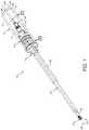
- FIG. 1is a perspective view of a surgical instrument according to an exemplary embodiment of the present disclosure.
- FIG. 2is an exploded perspective view of the surgical instrument of FIG. 1 with a drive assembly removed.
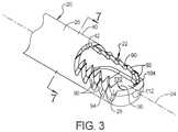
- FIG. 3is a perspective view of a clog-reducing tip of a cutting assembly of the surgical instrument of FIGS. 1 and 2 in accordance with an exemplary embodiment of the present disclosure.
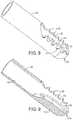
- FIG. 4is a fragmentary elevational view of the clog-reducing tip of the cutting assembly of FIG. 3 with removed material represented schematically.
- FIG. 5is another fragmentary elevational view of the clog-reducing tip of the cutting assembly of FIG. 3 .
- FIG. 6is another fragmentary elevational view of the clog-reducing tip of the cutting assembly of FIG. 3 .
- FIG. 7a cross-sectional view of the cutting assembly of FIG. 3 taken along lines 7 - 7 .
- FIG. 8is a perspective view of the clog-reducing tip according to another exemplary embodiment of the present disclosure.
- FIG. 9is fragmentary perspective view of the clog-reducing tip of FIG. 8 .
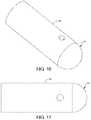
- FIG. 10is a perspective view of the clog-reducing tip according to another exemplary embodiment of the present disclosure.
- FIG. 11is fragmentary perspective view of the clog-reducing tip of FIG. 10 .
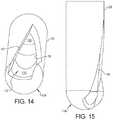
- FIG. 12is a perspective view of the clog-reducing tip according to another exemplary embodiment of the present disclosure.
- FIG. 13is elevational view of the clog-reducing tip of FIG. 12 .
- FIG. 14is an angled view of the clog-reducing tip of FIG. 12 .
- FIG. 15is a plan view of the clog-reducing tip of FIG. 12 .
- FIGS. 16-19are diagrammatic views illustrating a machined process for forming the clog-reducing tip of FIGS. 12-15 .
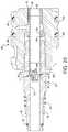
- FIG. 20is a cross-sectional view of the surgical instrument of FIG. 1 taken along lines 20 - 20 .
- the surgical instrument 10is shown for use in a medical procedure for a patient (not shown).
- the surgical instrument 10is an ENT shaver that is disposable and used for resecting sinus bone and tissue during endoscopic sinus surgery.
- the surgical instrument 10includes a drive assembly, generally indicated at 12 and shown in phantom lines, and a cutting assembly, generally indicated at 14 , removably coupled to the drive assembly 12 .
- the drive assembly 12is used to rotate a portion of the cutting assembly 14 to remove tissue, bone, etc. from a surgical site of the patient.
- the surgical instrument 10may be operated by a user (not shown) such as a surgeon.
- the drive assembly 12includes a housing 15 extending axially.
- the housing 15is generally cylindrical in shape.
- the drive assembly 12also includes a motor 16 disposed in the housing 15 and having a rotatable drive element 18 coupled to the cutting assembly 14 .
- the motor 16may be of an electric or pneumatic type.
- the drive element 18is removably coupled to the cutting assembly 14 .
- the cutting assembly 14may be free of any motor.
- the cutting assembly 14may be configured to be disposable after a single-use, or series of uses. Because the cutting assembly 14 may not include any motors, the cost of the cutting assembly 14 may be reduced.
- the cutting assembly 14includes a plurality of tubes or tube assembly, generally indicated at 20 , extending axially between a distal end 23 and a proximal end 21 ( FIG. 20 ) opposite the distal end 23 .
- the tube assembly 20has a longitudinal axis 24 defined between the proximal end 21 and the distal end 23 .
- the tube assembly 20includes a window 22 , for example, a cutting window, near or at the distal end 23 with the window 22 adapted to be applied to a surgical site of a patient.
- the tube assembly 20includes a first, or outer, tube 26 and a second, or inner, tube 28 .
- the inner tube 28is coupled to the drive assembly 102 and rotatable by the drive element 18 relative to the outer tube 26 .
- the inner tube 28may be removably coupled to the drive element 18 , for example, in an embodiment where the cutting assembly 14 is disposable after a single-use or series of uses.
- the outer tube 26is non-rotatable and the inner tube 28 is rotatable relative to the outer tube 26 .
- the inner tube 28and has a lumen 30 extending between the proximal end 21 and the distal end 23 of the tube assembly 20 .
- the inner tube 28may comprise a proximal region 32 and a distal region 34 to be described.
- the inner tube 28comprises, forms, or defines a first or inner cutting window 36 at or near the distal end 23 of the tube assembly 20 , such as within the distal region 34 of the inner tube 28 .
- Each of the inner tube 28 and the outer tube 26may be generally hollow cylinders extending axially and have a generally circular cross-sectional shape.
- the outer tube 26has a diameter greater than a diameter of the inner tube 28 such that the inner tube 28 is disposed within the outer tube 26 .
- the outer tube 26has a lumen extending between the proximal end 21 and the distal end 23 of the tube assembly 20 with the inner tube 28 at least partially disposed within the lumen of the outer tube 26 .
- the inner tube 28has an axial length longer than an axial length of the outer tube 26 such that the inner tube 28 extends past a proximal region 38 of the outer tube 26 when the inner tube 28 is disposed within the outer tube 26 .
- the outer tube 26may comprise the proximal region 38 and a distal region 40 as shown in FIG. 2 .
- the outer tube 26forms a second or outer cutting window 42 at or near the distal end 23 of the tube assembly, such as within the distal region 40 of the outer tube 26 .
- the inner cutting window 36 and the outer cutting window 42define the cutting window 22 of the tube assembly 20 .
- the outer tube 26may include a radial reduction step 44 within the distal region 34 to allow an outer surface of the inner tube 28 and an inner surface of the outer tube 26 to be close together.
- the tube assembly 20may further include a non-rotatable sheath or third or covering tube 46 disposed over a portion of the outer tube 26 .
- the covering tube 46has an axial length less than an axial length of the outer tube 26 .
- the covering tube 46may be angled, straight, or malleable. It should be appreciated that the covering tube 46 is optional.
- the covering tube 46is coupled to a connecting hub 68 to be described.
- any suitable tubing configurationmay be utilized so long as the cutting assembly 14 defines the cutting window 22 and can be driven by the drive assembly 12 .
- the inner tube 28 and outer tube 26are made of a metal material such as stainless steel or a non-metallic material such as a composite depending on the application.
- the covering tube 46may be made of a metal material or a non-metallic material such as a composite depending on the application. It should be appreciated that a wall thickness of the inner tube 28 and the outer tube 26 is relatively thin such as approximately 0.1 to approximately 0.5 millimeters (mm) to allow the tube assembly 20 to be of a relatively small diameter and also to be lightweight.
- the diameters of the inner tube 28 and the outer tube 26have a relatively small diameter such as approximately 2.0 mm to approximately 5.0 mm so as to work in a small opening of a nasal cavity or oral cavity of the patient and to prevent the user's view from being obstructed.
- the tube assembly 20may have a bend (not shown) near the distal end 23 .
- the inner tube 28 and the outer tube 26may be scaled larger or smaller depending on the application.
- the cutting assembly 14also includes a drive hub, generally indicated at 48 , disposed about a proximal end of the inner tube 28 to allow the inner tube 28 to be connected to the drive element 18 for rotation of the inner tube 28 about the longitudinal axis 24 .
- the drive hub 48includes a hub member 50 disposed about the inner tube 28 .
- the hub member 50extends axially and is generally cylindrical in shape.
- the hub member 50has an aperture 52 extending axially at least partially therethrough to receive the inner tube 28 as illustrated in FIG. 2 .
- the hub member 50may also include a plurality of ridges 54 extending radially and axially and spaced circumferentially thereabout.
- the hub member 50may further include a reduced diameter portion 56 adjacent the ridges 54 .
- the reduced diameter portion 56 of the hub member 50defines a reduced aperture 53 in communication with the aperture 52 with the reduced aperture 53 being smaller in diameter than the aperture 52 (see FIG. 20 ).
- the decrease in diameter from the aperture 52 to the reduced aperture 53forms a lip 55 adapted to be positioned adjacent to or in an abutting relationship with the proximal end 21 of the tube assembly 20 in a manner to be described.
- the hub member 50also includes a flange 58 extending radially at a distal end thereof.
- the hub member 50may be made of a non-metallic material.
- the hub member 50may be integral, unitary, and formed as one-piece.
- the drive hub 48can also include a spring 60 and a seal 62 such as an o-ring disposed about the hub member 50 at a proximal end thereof in the reduced diameter portion 56 .
- the drive hub 48may include a washer 64 and a seal 66 such as an o-ring at a distal end thereof disposed about the distal end of the inner tube 28 . It should be appreciated that the drive hub 48 allows for rotation of the inner tube 28 and may allow for the transfer of fluid through the inner tube 28 . It should also be appreciated that a variety of drive coupling configurations may be used with the cutting assembly 14 .
- the cutting assembly 14further includes a connecting hub, generally indicated at 68 , disposed about the inner tube 28 and a portion of the drive hub 50 to allow the drive assembly 12 to be removably coupled to the cutting assembly 14 .
- the connecting hub 68includes a housing hub 70 adapted to be engaged by a least a portion of a hand of a user and supporting the outer tube 26 or the covering tube 46 .
- the housing hub 70includes an aperture 72 extending axially therethrough to receive the outer tube 26 or the covering tube 46 .
- the housing hub 70may include a plurality of grip members 74 extending radially and axially and a flange 76 extending radially outwardly at one end to support one or more fingers of a hand.
- the connecting hub 68also includes a coupling member 78 disposed about the inner tube 28 .
- the coupling member 78extends axially and is generally cylindrical in shape.
- the coupling member 70has an aperture 72 extending axially therethrough to receive the inner tube 28 .
- the coupling member 78includes a cavity 80 extending axially into the proximal end thereof to receive a distal end of the fluid coupling.
- the coupling member 78may include one or more ridges 82 extending radially and spaced circumferentially from each other at the proximal end to be coupled to the housing 15 of the drive assembly 12 .
- the coupling member 78may include one or more grooves 84 extending radially inward and circumferentially and spaced axially from each other and one or more seals 86 such as o-rings disposed in the grooves 84 .
- the connecting hub 68is made of a non-metallic material.
- the connecting hub 68may be integral, unitary, and formed as one-piece. It should be appreciated that the connecting hub 68 allows for the coupling of the drive assembly 12 to the cutting assembly 14 .
- the cutting window 22includes the inner cutting window 36 in the inner tube 28 formed as an opening extending axially and diametrically through a wall on one side near the distal end 23 of the tube assembly 20 .
- the cutting window 22also includes the outer cutting window 42 in the outer tube 26 formed as an opening extending axially and diametrically through a wall on one side near the distal end 23 of the tube assembly 20 .
- the inner and outer cutting windows 36 and 42are generally elongated and oval in shape, but may be any suitable shape.
- the inner cutting window 36may include at least one or more cutting edges 90 .
- the cutting edge 90may include a plurality of teeth 92 forming a serrated edge.
- the outer cutting window 42may include at least one or more cutting edges 94 .
- the cutting edge 94may include a plurality of teeth 92 forming a serrated edge.
- the inner cutting window 36is adapted to be temporarily aligned radially with the outer cutting window 42 to receive material within the cutting window 22 as the inner tube 28 rotates within the outer tube 26 . As the inner tube 28 rotates within the outer tube 26 , the inner and outer cutting windows 36 and 42 are removed from radial alignment such that the cutting edges 90 and 94 cut or reduce the material positioned within the cutting window 22 of the tube assembly 20 .
- the surgical instrument 10includes an irrigation connection 95 on the housing 15 for connection to a fluid source and an irrigation path or passage 96 extending through the housing 15 between the irrigation connection 95 and the cutting assembly 14 and between the inner tube 28 and the outer tube 26 to the window 22 to provide lubrication.
- the surgical instrument 10also includes an aspiration or suction connection 97 on the housing 15 for connection to a suction source and an aspiration or suction path or passage 98 extending through the housing 15 between the suction connection 97 and the first cutting window 36 of the inner tube 28 .
- FIGS. 4-6show fragmentary elevational views of a clog-reducing tip, generally indicated at 104 , in accordance with an exemplary embodiment of the present disclosure.
- the cutting window 22 of the tube assembly 20comprises a distal boundary 103 and a proximal boundary 101 opposite the distal boundary 103 .
- the boundaries 101 and 103may be defined as an imaginary plane extending perpendicularly to the longitudinal axis 24 of the tube assembly 20 at a proximal-most point and a distal-most point of the cutting window 22 , respectively.
- the outer tube 26projects distal to the inner tube 28 to define the proximal boundary 101 of the cutting window 22 , and the distal end 23 the inner tube 28 is positioned proximally (i.e., within) the outer tube 26 to define the distal boundary 103 of the cutting window 22 .
- the proximal and distal boundaries 101 and 103may be considered the proximal-most and distal-most points of the cutting window 22 , respectively, when the cutting window 22 is viewed in plan.
- a portion of the inner tube 28 distal to the proximal boundary 101 of the cutting window 22defines the distal region 34 of the inner tube 28 .
- the clog-reducing tip 104 of the tube assembly 20comprises a projection 112 within the lumen 30 of the inner tube 28 .
- the projection 112is adapted to reduce the size of material removable through the cutting window 22 , thereby reducing clogging of the tube assembly 20 .
- at least a portion of the projection 112is positioned distal to the proximal boundary 101 (in a direction of arrow 102 in FIG. 4 ) to provide a reduced cross sectional area to said lumen 30 relative to the cross sectional area of the lumen 30 proximal to the projection 112 .
- the projection 112occupies a volume V 112 ( FIG. 5 ) within the distal region 34 of the inner tube 28 .
- the projection 112reduces the amount by which material 106 to be removed may penetrate the cutting window 22 . Consequently, the cutting action from rotating the inner tube 28 within the outer tube 26 (via the cutting edges 90 and 94 ) reduces the material 106 into sufficiently small bits before the material 106 may pass within the lumen 30 proximal to the cutting window 22 , thereby decreasing the likelihood of clogging of the tube assembly 20 .
- the reduced cross sectional area of the lumen 30may defined as the difference between the cross sectional area of the lumen 30 (e.g., ⁇ *d with d being the diameter of the lumen 30 ) and a cross sectional area of the projection 112 .
- a ratio of the reduced cross sectional area of the lumen 30 to the cross sectional area of the lumen 30is within the range of 1:1.1 to 1:2.0, and more particularly within the range 1:1.3 to 1:1.8, and even more particularly within the range of 1:1.5 to 1:1.6.
- the reduced cross sectionalis adapted to ensure that no dimension of material 106 (e.g., bone and/or tissue chip) is larger than the cross sectional area of the lumen 30 , and more particularly less than the cross sectional area of the lumen 30 by a predetermined factor based on the ratio described above.
- the volume V 112 of the projection 112 disposed within the distal region 34occupies within the range of 10%-70% of a volume V 20 of the distal region 34 of the tube assembly 20 , and more particularly within the range of 20%-60% of the volume V 20 of the distal region 34 (see FIG. 5 ).
- the materialis able to penetrate the cutting window to contact the inner tube opposite the cutting window such that the size of the reduced material is approximately equal to the diameter of the lumen.
- the reduced material having a size approximately equal to the diameter of the lumenincreases the likelihood of the reduced material clogging within the lumen, particularly near the cutting window. Furthermore, in instances where the axial length of the cutting window is greater than the diameter of the lumen, the likelihood of the reduced material clogging is further increased in conventional ENT shavers.
- the clog-reducing tip 104 of the present disclosuresignificantly reduces the likelihood of clogging by, for example, providing that the distance from the proximal boundary 101 of the cutting window 22 at the outer tube 26 to a nearest point on the projection 112 (approximated as point 105 as shown in FIG. 4 ) is less than the diameter of the lumen 30 .
- any reduced material 106 that may pass through the “throat”i.e., the distance from cutting window 22 to the nearest point 105
- the projection 112Prior to the material being sufficiently reduced to pass through the “throat” of the inner tube 28 , the projection 112 (and the proximal boundary 101 of the cutting window 22 ) maintains the material 106 in a position such that the cutting action continues to reduce the material 106 with each rotation of the inner tube 28 .
- the material 106possibly remaining positioned near the cutting window 22 for increased time, empirical investigations have shown minimal effect on material removal capacity of the tube assembly 20 incorporating the clog-reducing tip 104 with near or total elimination of clogging commonly associated with conventional ENT shavers.
- the projection 112may extend within the lumen 30 from near the distal end 23 of the tube assembly 20 to a position proximal to (i.e., in the direction of arrow 100 ) the proximal boundary 101 .
- another portion 113 of the projection 112may be positioned proximal to the proximal boundary 101 .
- the axial length L 112 of the projection 112may be greater than the axial length L 22 of the cutting window 22 .
- the axial length L 112 of the projection 112may be greater than an axial length L 42 of the outer cutting window 42 and/or less than an axial length L 36 of the inner cutting window 36 .
- the projection 112may extend even more proximally to the proximal boundary 101 than shown in FIGS. 4 and 6 with a proximal second portion 110 b to be described having a shallower taper.
- the projection 112 of the clog-reducing tip 104has a shelf or an inner surface 110 .
- the inner surface 110is displaced radially inward relative to an interior surface 108 of the lumen 30 (i.e., proximal to the projection 112 ) towards the longitudinal axis 24 of the tube assembly 20 .
- the projection 112may be angled relative to the interior surface 108 of the lumen 30 .
- a line extending between distal and proximal ends of the projection 112may be oriented at an angle ⁇ in the range of approximately 5 degrees to approximately 40 degrees relative to the interior surface 108 of the lumen 30 .
- the angle ⁇is between approximately 10 degrees and approximately 30 degrees, and more particularly between approximately 15 degrees and approximately 25 degrees.
- the angle ⁇generally provides a profile (when viewed in elevation as shown in FIGS. 4-6 ) to the projection 112 that tapers in the direction of arrow 100 .
- a distance from the longitudinal axis 24 to the projection 112 at the distal boundary 103 of the cutting window 22is less than a distance from the longitudinal axis 24 from the projection 112 at the proximal boundary 101 of the cutting window 22 such that the projection 112 tapers in the direction towards the proximal boundary 101 .
- the tapering of the projection 112advantageously maintains the material 106 near the distal boundary 103 closer to the cutting edges 90 and 94 to reduces the material 106 into smaller bits as the reduced material 106 moves along the inner surface 110 of the projection 112 towards the lumen 30 proximal to the cutting window 22 .
- the tapering of the projection 112also ensures a gradual transition through the “throat,” as previously described, such that reduced material 106 passing through the “throat” immediately encounters a greater cross sectional area of the lumen 30 and is quickly urged proximally within the lumen 30 under forces from the suction source.
- the inner surface 110 of the projection 112further comprises or is defined by a distal first portion 110 a and the proximal second portion 110 b proximal to the distal first portion 110 a .
- the distal first portion 110 amay be oriented substantially parallel to the longitudinal axis 24 of the tube assembly 20 .
- the distal first portion 110 amay be substantially planar when viewed in elevation.
- the proximal second portion 110 bmay be sloped or angled relative to the distal first portion 110 a and the interior surface 108 of the lumen 30 .
- the proximal second portion 110 bmay be arcuate when viewed in elevation to provide a smooth transition to the distal first portion 110 a .
- the proximal second portion 110 bmay be oriented at an angle ⁇ in the range of approximately 20 degrees to approximately 60 degrees relative to the interior surface 108 of the lumen 30 . In other embodiments, the angle ⁇ is between approximately 30 degrees and approximately 50 degrees.
- the projection 112may be positioned about the longitudinal axis 24 radially opposite the cutting window 22 of the tube assembly 20 , and more particularly radially opposite the inner cutting window 36 .
- the relative positioning between the projection 112 and the inner cutting window 36remains constant as the inner tube 28 rotates within the outer tube 26 .
- the radial position of the cutting window 22 of FIG. 7is approximated between lines W 1 and W 2 with the projection 112 being positioned about the longitudinal axis 24 substantially opposite the space between lines W 1 and W 2 .
- the projection 112is positioned about a circumference of the lumen 30 in a manner sufficient to suitably reduce the material 106 to prevent clogging of the tube assembly 20 . In certain embodiments, the projection 112 is positioned about less than one half of the circumference of the lumen 30 .
- the axial cross sectional view FIG. 7shows one side of the projection 112 radially positioned approximately at the 4 o'clock position, and another side of the projection 112 radially positioned approximately at the 8 o'clock position.
- an angle ⁇ about the longitudinal axis 24 and extending between opposing sides of the projection 112within the range of approximately 70 degrees to approximately 180 degrees, and more particularly with the range of approximately 90 degrees to approximately 160 degrees, and even more particularly with the range of approximately 110 degrees to approximately 150 degrees.
- Other suitable values for the angle ⁇are contemplated based on, at least in part, the diameter of the lumen 30 , the intended application of the surgical instrument 10 , and the like.
- the clog-reducing tip 104includes an insert secured within the lumen 30 of the inner tube 28 .
- the insertdefines the projection 112 and forms the inner surface 110 .
- the insertmay be bonded to the lumen 30 of the inner tube 28 .
- the insertmay include an outer surface 111 and the inner surface 110 with the outer surface 111 shaped to conform a portion of the lumen 30 (see FIG. 7 ).
- the inner surface 110may define the projection 112 .
- the insertmay have a thickness defined between the inner surface 110 and the outer surface 111 with the thickness of the insert tapering in an axial direction; i.e., the direction 100 towards the proximal boundary 101 of the cutting window 22 . It is also understood that the thickness of the insert may taper radially about the longitudinal axis 24 of the tube assembly 20 , as shown in FIG. 7 .
- the projection 112is defined by the lumen 30 distal to the proximal boundary 101 being formed radially inwardly towards the longitudinal axis 24 .
- the projection 112 of FIGS. 4-6are within the lumen 30 with the inner tube 28 having a generally cylindrical outer profile to the distal end 23 of the tube assembly 20
- the FIGS. 10 and 11show the inner tube 28 near the distal end 23 (e.g., the distal region 34 ) deformed inwardly towards the longitudinal axis 24 .
- the lumen 30 of the inner tube 28is corresponding deformed inwardly and consequently defines the projection 112 providing the reduced cross sectional area of the lumen 30 as previously described.
- the inwardly deformed portion of the inner tube 28may be constructed through stamping, drawing, or similarly suitable manufacturing process.
- the clog-reducing tip 104includes the inner surface 110 formed by boring out an eccentric borehole within the distal region 34 of the inner tube 28 .
- the boreholeis eccentric with respect to the longitudinal axis 24 of the tube assembly 24 .
- the eccentric boreholeis in communication with the cutting window 22 and the lumen 30 of the inner tube 28 .
- This type of tipwould typically be machined.
- the inner surface 110has a smaller cross-section at the first cutting window 36 .
- the process of machining the clog-reducing tip 104is illustrated in FIGS. 16-19 .
- the present disclosureprovides a method, according to one embodiment of the present disclosure, for operating the surgical instrument 10 on a patient.
- the methodincludes the steps of providing the cutting assembly 14 including the tube assembly 20 extending axially.
- the tube assembly 20includes the rotatable inner tube 28 having the lumen 30 disposed coaxially within the outer tube 26 .
- the inner tube 28forms the inner cutting window 36
- the outer tube 26forms the outer cutting window 42 .
- the inner and outer cutting windows 36 , 42define the cutting window 22 of the tube assembly 20 .
- the methodmay also include the steps of providing the projection 112 within the lumen 30 of the inner tube 28 with at least a portion of the projection 112 disposed within the distal region 34 of the inner tube 28 with the projection 112 .
- the projection 112positioned distal to the proximal boundary 101 of the cutting window 22 .
- the projection 112provides a reduced cross sectional area to the inner tube 28 relative to a cross sectional area of the lumen proximal to the projection 112 .
- the projection 112is the volume V 112 that occupies the volume V 20 of the lumen 30 distal to the proximal boundary 101 of the cutting window 22 .
- the methodincludes the step of applying the cutting window to a surgical site of a patient and rotating the inner tube 28 relative to the outer tube 26 by the drive assembly 12 to cut the material 106 by an interaction of the inner cutting window 36 and the outer cutting window 42 on the patient, wherein the projection 112 reduces the size of the material 106 removed through the cutting window 22 to reduce clogging of the tube assembly 20 .
- FIG. 20is a cross sectional view of a portion of the surgical instrument of FIG. 1 , showing in particular an interface 114 between the tube assembly 20 and the drive hub 48 .
- the hub member 50 of the drive hub 48includes the reduced diameter portion 56 defining the reduced aperture 53 in communication with the aperture 52 of the drive hub 48 (and the connecting hub 68 ).
- the lip 55is formed by the decrease in diameter from the aperture 52 to the reduced aperture 53 .
- the inner tube 28has an axial length longer than an axial length of the outer tube 26 such that the inner tube 28 extends past the proximal region 38 of the outer tube 26 and into the connecting hub 68 and the drive hub 48 , as shown in FIG. 20 .
- the inner tube 28is slidably inserted within the aperture 52 of the drive hub 48 and positioned adjacent or in an abutting relationship with the lip 55 .
- the lip 55facilitates appropriate axial positioning the tube assembly 20 relative to the housing 15 and other structures of the surgical instrument 10 .
- the lumen 30 of the inner tube 28is in fluid communication with the reduced aperture 53 of the drive hub 48 , as shown in FIG. 20 , such that reduced material 106 may pass from the lumen 30 to the suction source.
- the diameter of the lumen 30 of the inner tube 28is less than the diameter of the reduced aperture 53 at the interface 114 .
- the reduced material 106moves from a smaller cross sectional area of the lumen 30 to a greater cross sectional area of the reduced aperture 53 as the material 106 passes through the interface 114 .
- the passage through which the reduced material is movingexpands, thereby reducing the likelihood of clogging.
- the diameter of the lumen 30 of the inner tube 28was greater than the diameter of the reduced aperture 53 , the reduced material 106 may become lodged on the lip 55 and increase the likelihood of clogging at the interface 114 .
- a cutting assembly for a surgical instrumenthaving a drive assembly, said cutting assembly comprising: a tube assembly comprising a cutting window near a distal end and adapted to be applied to a surgical site of a patient, an outer tube, an inner tube coaxially disposed within and rotatable relative to said outer tube with the drive assembly with said inner tube comprising a lumen; and a drive hub coupled to said inner tube with said drive hub defining an aperture adapted to slidably receive a proximal end of said inner tube, and defining a reduced aperture in communication with said aperture, wherein a diameter of said reduced aperture is less than a diameter of said aperture, wherein a diameter of said lumen is less than said diameter of said reduced aperture when said proximal end of said inner tube is slidably received within said aperture to reduce clogging of said surgical instrument as removed material moves from said lumen to said reduced aperture of said drive hub.
- a lipis formed at an interface between said aperture and said reduced aperture with said
- the surgical instrument 10 of the present disclosurereduces the occurrence of the clogging by providing the clog-reducing tip 104 having the projection 112 for reducing a cross sectional area of the lumen 30 distal to the proximal boundary 101 of the cutting window 22 and/or for providing the volume V 112 within the volume V 20 of the distal region 34 of the tube assembly 20 .
- the size of the material 106 that may enter the distal region 34 of the inner tube 28is limited and maintained in a position to be further reduced by the cutting action. Further, only material 106 of sufficiently reduced sized may pass through the “throat” of the tube assembly 20 , after which the reduced material 106 encounters the larger cross sectional of the lumen 30 also under the influence of suction.
- the projection 112may be the insert secured with the lumen 30 of the inner tube 28 , or formed integrally with the same, such as by deforming the distal region 34 of the inner tube 28 , providing the borehole eccentric to the longitudinal axis 24 of the tube assembly 24 , or suitably milling within the inner tube 28 to define the projection 112 .
- the surgical instrument 10 of the present disclosurecuts and aspirates tissue as per current shaver systems utilizing suction. It should be appreciated that, in another embodiment, the surgical instrument 10 may be used with the surgical tools or be a dedicated tool or instrument.
- a cutting assembly for a surgical instrument for cutting tissuesaid cutting assembly being configured to be coupled to a drive assembly including a motor having a rotatable drive element enclosed in a housing and said cutting assembly comprising: a rotatable first tube having a lumen, said lumen having a proximal region and a distal region, said first tube forming a first cutting window in said distal region; a second tube disposed over said first tube, said second tube having a proximal region and a distal region, said second tube forming a second cutting window in said distal region; said first tube being rotatable relative to said second tube; said proximal region of said window of said lumen having a cross-sectional area greater than a cross-sectional area of said distal region of said lumen such that tissue cut by an interaction of said first cutting window and said second cutting window is of suitable dimensions to allow passage through said first cutting window and said distal region of said lumen to said proximal region of said lumen to prevent clogging of
- Clause 2A cutting assembly as set forth in clause 1 wherein said proximal region of said lumen has an interior surface and said distal region of said lumen has an inner surface opposite said first cutting window.
- Clause 3A cutting assembly as set forth in clause 2 wherein said inner surface is displaced radially inward relative to said interior surface.
- Clause 4A cutting assembly as set forth in clause 2 wherein said inner surface extends radially and axially at an angle greater than zero relative to said interior surface.
- Clause 5A cutting assembly as set forth in clause 2 including an insert disposed within said distal region of said lumen opposite said first cutting window and forming said inner surface.
- Clause 7A cutting assembly as set forth in clause 5 wherein said insert includes said inner surface extending radially and axially at an angle greater than zero relative to said interior surface.
- Clause 8A cutting assembly as set forth in clause 5 wherein said insert has one of a generally arcuate, semi-circular, and rectangular cross-sectional profile.
- Clause 11A cutting assembly as set forth in clause 2 wherein said inner surface extends axially from a distal end of said distal region of said lumen to one of less than and at least a proximal end of said first cutting window.
- Clause 12A cutting assembly as set forth in clause 11 wherein said first cutting window has an axial length less than an axial length of one of said inner surface and said second cutting window.
- Clause 13A cutting assembly as set forth in clause 11 wherein an angle of said inner surface to a tube wall of said distal region of said lumen is between approximately 20 degrees and approximately 90 degrees.
- Clause 14A cutting assembly as set forth in clause 11 wherein said inner surface has a radial height greater than a radial height of said interior surface.
- Clause 15A cutting assembly as set forth in clause 1 including a third tube disposed over said second tube.
- Clause 16A cutting assembly as set forth in clause 1 wherein said distal region of said lumen has a profile formed by one of a drawing process and a machined process.
- Clause 17A cutting assembly as set forth in clause 16 wherein said distal region of said lumen has a non-circular cross-section.
- Clause 18A cutting assembly as set forth in clause 1 wherein said first cutting window includes at least one cutting edge.
- Clause 19A cutting assembly as set forth in clause 1 including an aspiration path connected to either one of said first tube and said second tube.
- Clause 20A cutting assembly as set forth in clause 1 wherein a cross-section of said distal region of said lumen and a cross-section of said proximal region of said lumen has a ratio of one of 1:1.5, 1:3, and 1:6.
- Clause 21A cutting assembly as set forth in clause 1 wherein an axial length of said first cutting window relative to a diameter of said distal region of said lumen is such that no dimension of a bone chip that is cut is larger than a diameter of said lumen in said proximal region.
- a surgical instrument for use on a patientcomprising: a cutting assembly including a plurality of tubes extending axially, said tubes comprising at least a rotatable inner tube having a lumen, said lumen having a proximal region and a distal region, said inner tube forming an inner cutting window in said distal region, an outer tube disposed over said inner tube, said outer tube having a proximal region and a distal region, said outer tube forming an outer cutting window in said distal region, said inner tube being rotatable relative to said outer tube; a drive assembly including a motor having a rotatable drive element, a housing for enclosing said motor and being removably coupled to said cutting assembly, a suction connection on said housing for connection to a suction source, and a suction passage extending from said inner window through said inner tube and through said housing to said suction connection; an irrigation connection on said housing for connection to a fluid source; an irrigation passage extending through said housing between said
- Clause 23A method of operating a surgical instrument for use on a patient, said method comprising the steps of: providing a cutting assembly including a plurality of tubes extending axially, the tubes comprising at least a rotatable inner tube having a lumen, the lumen having a proximal region and a distal region, the inner tube forming an inner cutting window in the distal region, an outer tube disposed over the inner tube, the outer tube having a proximal region and a distal region, the outer tube forming an outer cutting window in said distal region, the inner tube being rotatable relative to the outer tube; providing a drive assembly including a motor having a rotatable drive element, a housing for enclosing the motor and being removably coupled to the cutting assembly, a suction connection on the housing for connection to a suction source, and a suction passage extending from the inner window through the inner tube and through the housing to the suction connection; providing the proximal region of the lumen having a cross
- Clause 24A surgical instrument, cutting assembly, and method as disclosed and described herein, including equivalents not specifically recited herein.
Landscapes
- Health & Medical Sciences (AREA)
- Surgery (AREA)
- Life Sciences & Earth Sciences (AREA)
- Molecular Biology (AREA)
- Animal Behavior & Ethology (AREA)
- Nuclear Medicine, Radiotherapy & Molecular Imaging (AREA)
- Veterinary Medicine (AREA)
- Public Health (AREA)
- Engineering & Computer Science (AREA)
- Biomedical Technology (AREA)
- Heart & Thoracic Surgery (AREA)
- Medical Informatics (AREA)
- General Health & Medical Sciences (AREA)
- Orthopedic Medicine & Surgery (AREA)
- Pulmonology (AREA)
- Dentistry (AREA)
- Oral & Maxillofacial Surgery (AREA)
- Otolaryngology (AREA)
- Surgical Instruments (AREA)
Abstract
Description
Claims (15)
Priority Applications (1)
| Application Number | Priority Date | Filing Date | Title |
|---|---|---|---|
| US16/316,500US11020139B2 (en) | 2016-07-14 | 2017-07-14 | Cutting assembly for surgical instrument with clog reducing tip |
Applications Claiming Priority (3)
| Application Number | Priority Date | Filing Date | Title |
|---|---|---|---|
| US201662362117P | 2016-07-14 | 2016-07-14 | |
| PCT/US2017/042101WO2018013906A1 (en) | 2016-07-14 | 2017-07-14 | Cutting assembly for surgical instrument with clog reducing tip |
| US16/316,500US11020139B2 (en) | 2016-07-14 | 2017-07-14 | Cutting assembly for surgical instrument with clog reducing tip |
Related Parent Applications (1)
| Application Number | Title | Priority Date | Filing Date |
|---|---|---|---|
| PCT/US2017/042101A-371-Of-InternationalWO2018013906A1 (en) | 2016-07-14 | 2017-07-14 | Cutting assembly for surgical instrument with clog reducing tip |
Related Child Applications (1)
| Application Number | Title | Priority Date | Filing Date |
|---|---|---|---|
| US17/331,795ContinuationUS11766274B2 (en) | 2016-07-14 | 2021-05-27 | Cutting assembly for surgical instrument with clog-reducing hub |
Publications (2)
| Publication Number | Publication Date |
|---|---|
| US20190223898A1 US20190223898A1 (en) | 2019-07-25 |
| US11020139B2true US11020139B2 (en) | 2021-06-01 |
Family
ID=59409767
Family Applications (4)
| Application Number | Title | Priority Date | Filing Date |
|---|---|---|---|
| US16/316,500Active2038-03-12US11020139B2 (en) | 2016-07-14 | 2017-07-14 | Cutting assembly for surgical instrument with clog reducing tip |
| US17/331,795Active2037-10-09US11766274B2 (en) | 2016-07-14 | 2021-05-27 | Cutting assembly for surgical instrument with clog-reducing hub |
| US18/227,405ActiveUS12329405B2 (en) | 2016-07-14 | 2023-07-28 | Cutting assembly for surgical instrument with clog-reducing tip |
| US19/220,527PendingUS20250281196A1 (en) | 2016-07-14 | 2025-05-28 | Cutting Assembly For Surgical Instrument With Clog-Reducing Tip |
Family Applications After (3)
| Application Number | Title | Priority Date | Filing Date |
|---|---|---|---|
| US17/331,795Active2037-10-09US11766274B2 (en) | 2016-07-14 | 2021-05-27 | Cutting assembly for surgical instrument with clog-reducing hub |
| US18/227,405ActiveUS12329405B2 (en) | 2016-07-14 | 2023-07-28 | Cutting assembly for surgical instrument with clog-reducing tip |
| US19/220,527PendingUS20250281196A1 (en) | 2016-07-14 | 2025-05-28 | Cutting Assembly For Surgical Instrument With Clog-Reducing Tip |
Country Status (8)
| Country | Link |
|---|---|
| US (4) | US11020139B2 (en) |
| EP (3) | EP3721820B1 (en) |
| JP (2) | JP7007355B2 (en) |
| KR (1) | KR102533518B1 (en) |
| CN (3) | CN109475366B (en) |
| AU (2) | AU2017294760B2 (en) |
| CA (1) | CA3030801A1 (en) |
| WO (1) | WO2018013906A1 (en) |
Cited By (2)
| Publication number | Priority date | Publication date | Assignee | Title |
|---|---|---|---|---|
| US11766274B2 (en) | 2016-07-14 | 2023-09-26 | Stryker European Operations Holdings Llc | Cutting assembly for surgical instrument with clog-reducing hub |
| US12414792B2 (en) | 2022-08-31 | 2025-09-16 | Medtronic Xomed Llc | Microdebrider with stability interface bushing |
Families Citing this family (15)
| Publication number | Priority date | Publication date | Assignee | Title |
|---|---|---|---|---|
| WO2019094708A1 (en)* | 2017-11-09 | 2019-05-16 | Caldera Medical, Inc. | Rotary instruments and methods for intrauterine tissue resection |
| USD882787S1 (en)* | 2018-01-31 | 2020-04-28 | Beijing Smtp Technology Co., Ltd. | Ultrasonic cutter head |
| USD882788S1 (en)* | 2018-01-31 | 2020-04-28 | Beijing Smtp Technology Co., Ltd. | Ultrasonic cutter head |
| USD882084S1 (en)* | 2018-01-31 | 2020-04-21 | Beijing Smtp Technology Co., Ltd. | Ultrasonic cutter head |
| USD882790S1 (en)* | 2018-01-31 | 2020-04-28 | Beijing Smtp Technology Co., Ltd. | Ultrasonic cutter head |
| US11154318B2 (en) | 2019-02-22 | 2021-10-26 | Covidien Lp | Tissue resecting instrument including an outflow control seal |
| US11083486B2 (en) | 2019-03-08 | 2021-08-10 | Arthrex, Inc. | Rotary surgical shaver |
| US12029445B2 (en) | 2019-10-18 | 2024-07-09 | Meditrina, Inc. | Surgical instrument and method of use |
| JP7551738B2 (en)* | 2020-03-30 | 2024-09-17 | テルモ株式会社 | Medical Devices |
| US12390243B2 (en)* | 2020-05-20 | 2025-08-19 | Meditrina, Inc. | Fluid management systems and methods |
| AU2021396638A1 (en) | 2020-12-11 | 2023-06-29 | Stryker European Operations Limited | Cutting assembly with irrigation and aspiration |
| US12137960B2 (en) | 2021-05-25 | 2024-11-12 | Arthrex, Inc. | Surgical system with adaptive aspiration flow control |
| US12290274B2 (en) | 2021-05-25 | 2025-05-06 | Arthrex, Inc. | Dynamically controlling a distal window opening in a rotary surgical shaver |
| US20240065719A1 (en)* | 2022-08-31 | 2024-02-29 | Medtronic Xomed, Inc. | Microdebrider with improved cutting and reduced clogging |
| EP4570196A1 (en)* | 2023-12-11 | 2025-06-18 | Medtronic Xomed, LLC | Microdebrider with inner tube retention feature |
Citations (44)
| Publication number | Priority date | Publication date | Assignee | Title |
|---|---|---|---|---|
| JPS61259653A (en) | 1985-05-15 | 1986-11-17 | オリンパス光学工業株式会社 | Ultrasonic stone crushing probe |
| US4850354A (en) | 1987-08-13 | 1989-07-25 | Baxter Travenol Laboratories, Inc. | Surgical cutting instrument |
| US5286253A (en) | 1992-10-09 | 1994-02-15 | Linvatec Corporation | Angled rotating surgical instrument |
| US5411514A (en) | 1992-09-30 | 1995-05-02 | Linvatec Corporation | Bendable variable angle rotating shaver |
| US5601583A (en) | 1995-02-15 | 1997-02-11 | Smith & Nephew Endoscopy Inc. | Surgical instrument |
| US5741287A (en) | 1996-11-01 | 1998-04-21 | Femrx, Inc. | Surgical tubular cutter having a tapering cutting chamber |
| US5755731A (en) | 1994-04-15 | 1998-05-26 | Smith & Nephew Dyonics, Inc. | Curved surgical instrument with segmented inner member |
| US5766199A (en) | 1996-04-10 | 1998-06-16 | Linvatec Corporation | Endoscopic shaver blade with resilient cutting edges |
| US5843106A (en) | 1996-04-10 | 1998-12-01 | Linvatec Corporation | Endoscopic shaver blade with sharp outer edge |
| US5922003A (en) | 1997-05-09 | 1999-07-13 | Xomed Surgical Products, Inc. | Angled rotary tissue cutting instrument and method of fabricating the same |
| US6217598B1 (en)* | 1997-11-25 | 2001-04-17 | Linvatec Corporation | End-cutting shaver blade |
| US6503263B2 (en) | 2000-09-24 | 2003-01-07 | Medtronic, Inc. | Surgical micro-shaving instrument with elevator tip |
| US6533749B1 (en) | 1999-09-24 | 2003-03-18 | Medtronic Xomed, Inc. | Angled rotary tissue cutting instrument with flexible inner member |
| US6620180B1 (en) | 1998-09-09 | 2003-09-16 | Medtronic Xomed, Inc. | Powered laryngeal cutting blade |
| US6656195B2 (en) | 2000-09-22 | 2003-12-02 | Medtronic Xomed, Inc. | Flexible inner tubular members and rotary tissue cutting instruments having flexible inner tubular members |
| US20040059363A1 (en) | 2002-07-13 | 2004-03-25 | Alvarez Edgardo L. | System and method for performing irrigated nose and throat surgery |
| US20040243163A1 (en) | 2003-04-02 | 2004-12-02 | Gyrus Ent L.L.C | Surgical instrument |
| US20050090849A1 (en) | 2003-10-22 | 2005-04-28 | Adams Kenneth M. | Angled tissue cutting instruments and method of fabricating angled tissue cutting instrument having flexible inner tubular members of tube and single wrap construction |
| US7338495B2 (en) | 2003-10-22 | 2008-03-04 | Medtronic Xomed, Inc. | Angled tissue cutting instruments having flexible inner tubular members of tube and sleeve construction |
| US20080208194A1 (en) | 2007-02-13 | 2008-08-28 | Christine Bickenbach | Double cut shaver |
| US20090131816A1 (en) | 2006-12-13 | 2009-05-21 | Ritchie Paul G | Engagement Interface For Biopsy System Vacuum Module |
| US7699846B2 (en) | 2005-03-04 | 2010-04-20 | Gyrus Ent L.L.C. | Surgical instrument and method |
| US7854736B2 (en) | 2005-03-04 | 2010-12-21 | Gyrus Ent, L.L.C. | Surgical instrument and method |
| US7927361B2 (en) | 2005-11-29 | 2011-04-19 | Medtronic Xomed, Inc. | Method and apparatus for removing material from an intervertebral disc space, such as in performing a nucleotomy |
| US8109956B2 (en) | 2008-03-07 | 2012-02-07 | Medtronic Xomed, Inc. | Systems and methods for surgical removal of tissue |
| US8202288B2 (en) | 2004-01-21 | 2012-06-19 | Medtronic Xomed, Inc. | Angled tissue cutting instrument having variably positionable cutting window and indexing tool for use therewith |
| US8277474B2 (en) | 2004-05-26 | 2012-10-02 | Medtronic, Inc. | Surgical cutting instrument |
| US20130023882A1 (en) | 2011-02-15 | 2013-01-24 | Fabro Myra I L | Discectomy devices and related methods |
| US8409235B2 (en) | 2010-04-30 | 2013-04-02 | Medtronic Xomed, Inc. | Rotary cutting tool with improved cutting and reduced clogging on soft tissue and thin bone |
| US8435259B2 (en) | 2009-05-19 | 2013-05-07 | Stryker Corporation | Surgical tool arrangement and surgical cutting accessory for use therewith with the tool arrangement including a toothed cutting edge and a generally straight cutting edge |
| US8585724B2 (en) | 2011-01-25 | 2013-11-19 | Gyrus Ent, L.L.C. | Surgical cutting instrument with distal suction capability |
| EP2692305A1 (en) | 2011-06-20 | 2014-02-05 | Olympus Medical Systems Corp. | Ultrasound therapy device |
| US20140114300A1 (en) | 2012-10-19 | 2014-04-24 | Arqos Surgical, Inc. | Medical systems and methods |
| US8906053B2 (en) | 2007-11-12 | 2014-12-09 | Medtronic Xomed, Inc. | Systems and methods for surgical removal of brain tumors |
| US20150073364A1 (en) | 2012-04-26 | 2015-03-12 | Gyrus ACMI, Inc. d.b.s. Olympus Surgical Technologies America | Surgical instrument |
| WO2015048270A1 (en) | 2013-09-26 | 2015-04-02 | GYRUS ACMI, INC. (d/b/a OLYMPUS SURGICAL TECHNOLOGIES AMERICA) | Oblong endoscope sheath |
| US9308013B2 (en) | 2010-11-03 | 2016-04-12 | Gyrus Ent, L.L.C. | Surgical tool with sheath |
| US9687254B2 (en) | 2010-10-22 | 2017-06-27 | Medtronic Xomed, Inc. | Method and apparatus for removing material from an intervertebral disc space and preparing end plates |
| US9737322B2 (en) | 2014-09-08 | 2017-08-22 | Medtronic Xomed, Inc. | Method for resection of tumors and tissues |
| US10022144B2 (en) | 2015-04-17 | 2018-07-17 | Medtronic Xomed, Inc. | Surgical cutting instrument |
| US10166013B2 (en) | 2015-10-30 | 2019-01-01 | Medtronic Xomed, Inc. | Flexible member for angled system |
| US10206706B2 (en) | 2015-05-29 | 2019-02-19 | Medtronic Xomed, Inc. | Inner tubular member for angled rotary surgical instrument |
| US10321929B2 (en) | 2014-05-16 | 2019-06-18 | Gyrus Acmi, Inc. | Apparatus and method for cutting tissue |
| US20190216473A1 (en) | 2018-01-18 | 2019-07-18 | GYRUS ACMI, INC., d/b/a Olympus Surgical Technologies America | Debrider with declogging feature |
Family Cites Families (25)
| Publication number | Priority date | Publication date | Assignee | Title |
|---|---|---|---|---|
| JP3859257B2 (en)* | 1996-03-18 | 2006-12-20 | ニプロ株式会社 | Suture cutting device for intracardiac suture surgery |
| US7344546B2 (en) | 2000-04-05 | 2008-03-18 | Pathway Medical Technologies | Intralumenal material removal using a cutting device for differential cutting |
| US7247161B2 (en) | 2002-03-22 | 2007-07-24 | Gyrus Ent L.L.C. | Powered surgical apparatus, method of manufacturing powered surgical apparatus, and method of using powered surgical apparatus |
| US8162966B2 (en)* | 2002-10-25 | 2012-04-24 | Hydrocision, Inc. | Surgical devices incorporating liquid jet assisted tissue manipulation and methods for their use |
| US7879037B2 (en) | 2004-02-11 | 2011-02-01 | Medtronic Xomed, Inc. | High speed surgical cutting instrument |
| US9504521B2 (en)* | 2005-03-17 | 2016-11-29 | Stryker Corporation | Surgical tool arrangement |
| US7666200B2 (en)* | 2006-07-19 | 2010-02-23 | Target Medical Innovations Llc | Endoscopic cutting instrument with axial and rotary motion |
| DE102009010561A1 (en)* | 2009-02-16 | 2010-08-19 | Karl Storz Gmbh & Co. Kg | Medical instrument for cutting tissue |
| KR20120057643A (en)* | 2009-08-31 | 2012-06-05 | 스트리커 아일랜드 리미티드 | Surgical cutting accessory with flexible tube |
| US9259234B2 (en)* | 2010-02-11 | 2016-02-16 | Ethicon Endo-Surgery, Llc | Ultrasonic surgical instruments with rotatable blade and hollow sheath arrangements |
| US8348927B2 (en)* | 2010-07-30 | 2013-01-08 | Medtronic, Inc. | Tools and methods related to catheter delivery |
| US8475482B2 (en) | 2011-02-17 | 2013-07-02 | Gyrus Ent L.L.C. | Surgical instrument with distal suction capability |
| US9186166B2 (en)* | 2011-09-01 | 2015-11-17 | Depuy Mitek, Llc | Tissue shavers |
| US9351757B2 (en) | 2012-01-17 | 2016-05-31 | Covidien Lp | Material removal device and method of use |
| CN203123265U (en)* | 2013-01-30 | 2013-08-14 | 山东赛克赛斯药业科技有限公司 | Disposable delivering catheter |
| DE102013201784B4 (en)* | 2013-02-04 | 2015-05-28 | Geuder Ag | Device for cutting and suctioning tissue |
| US9486232B2 (en) | 2013-03-25 | 2016-11-08 | Hanshi Llc | Endoscopic cutting instruments having improved efficiency and reduced manufacturing costs |
| WO2014183051A1 (en)* | 2013-05-09 | 2014-11-13 | Gyrus Acmi, Inc., D.B.A. Olympus Surgical Technologies America | Oscillating lithotripter tip |
| ITTO20130471A1 (en)* | 2013-06-07 | 2014-12-08 | Cultraro Automazione Engineering S R L | LINEAR SHOCK ABSORBER WITH IMPROVED SHUTTER ELEMENT |
| KR20160043032A (en) | 2013-08-16 | 2016-04-20 | 스미스 앤드 네퓨, 인크. | Surgical instrument |
| WO2015175176A1 (en)* | 2014-05-13 | 2015-11-19 | Acclarent, Inc. | Apparatus for treating disorders of the ear, nose, and throat |
| CN204072237U (en)* | 2014-09-01 | 2015-01-07 | 江苏博朗森思医疗器械有限公司 | The fixed structure of small dimension tubular anastomat endless knife |
| KR101486456B1 (en) | 2014-11-26 | 2015-01-26 | (주)트리플씨메디칼 | Cannula body and lifting cannula having same, and method of manufacturing cannula body |
| CN204582243U (en)* | 2015-03-25 | 2015-08-26 | 南通市第二人民医院 | A kind of telescopic stomach tube |
| EP3721820B1 (en) | 2016-07-14 | 2022-01-19 | Stryker European Operations Holdings LLC | Cutting assembly for a surgical instrument having a drive assembly |
- 2017
- 2017-07-14EPEP20173664.2Apatent/EP3721820B1/enactiveActive
- 2017-07-14CNCN201780043525.5Apatent/CN109475366B/enactiveActive
- 2017-07-14AUAU2017294760Apatent/AU2017294760B2/enactiveActive
- 2017-07-14WOPCT/US2017/042101patent/WO2018013906A1/ennot_activeCeased
- 2017-07-14JPJP2019501494Apatent/JP7007355B2/enactiveActive
- 2017-07-14KRKR1020197004143Apatent/KR102533518B1/enactiveActive
- 2017-07-14EPEP22151281.7Apatent/EP4005512B1/enactiveActive
- 2017-07-14CACA3030801Apatent/CA3030801A1/enactivePending
- 2017-07-14CNCN202510856748.XApatent/CN120514449A/enactivePending
- 2017-07-14USUS16/316,500patent/US11020139B2/enactiveActive
- 2017-07-14CNCN202111633402.1Apatent/CN114271899B/enactiveActive
- 2017-07-14EPEP17745230.7Apatent/EP3484384B1/enactiveActive
- 2021
- 2021-05-27USUS17/331,795patent/US11766274B2/enactiveActive
- 2021-11-02JPJP2021179321Apatent/JP7550131B2/enactiveActive
- 2022
- 2022-10-11AUAU2022252708Apatent/AU2022252708B2/enactiveActive
- 2023
- 2023-07-28USUS18/227,405patent/US12329405B2/enactiveActive
- 2025
- 2025-05-28USUS19/220,527patent/US20250281196A1/enactivePending
Patent Citations (54)
| Publication number | Priority date | Publication date | Assignee | Title |
|---|---|---|---|---|
| JPS61259653A (en) | 1985-05-15 | 1986-11-17 | オリンパス光学工業株式会社 | Ultrasonic stone crushing probe |
| US4850354A (en) | 1987-08-13 | 1989-07-25 | Baxter Travenol Laboratories, Inc. | Surgical cutting instrument |
| US5411514A (en) | 1992-09-30 | 1995-05-02 | Linvatec Corporation | Bendable variable angle rotating shaver |
| US5286253A (en) | 1992-10-09 | 1994-02-15 | Linvatec Corporation | Angled rotating surgical instrument |
| US5755731A (en) | 1994-04-15 | 1998-05-26 | Smith & Nephew Dyonics, Inc. | Curved surgical instrument with segmented inner member |
| US5601583A (en) | 1995-02-15 | 1997-02-11 | Smith & Nephew Endoscopy Inc. | Surgical instrument |
| US5766199A (en) | 1996-04-10 | 1998-06-16 | Linvatec Corporation | Endoscopic shaver blade with resilient cutting edges |
| US5843106A (en) | 1996-04-10 | 1998-12-01 | Linvatec Corporation | Endoscopic shaver blade with sharp outer edge |
| US5741287A (en) | 1996-11-01 | 1998-04-21 | Femrx, Inc. | Surgical tubular cutter having a tapering cutting chamber |
| USRE38018E1 (en) | 1997-05-09 | 2003-03-04 | Medtronic Xomed, Inc. | Angled rotary tissue cutting instrument and method of fabricating the same |
| US5922003A (en) | 1997-05-09 | 1999-07-13 | Xomed Surgical Products, Inc. | Angled rotary tissue cutting instrument and method of fabricating the same |
| US6217598B1 (en)* | 1997-11-25 | 2001-04-17 | Linvatec Corporation | End-cutting shaver blade |
| US6620180B1 (en) | 1998-09-09 | 2003-09-16 | Medtronic Xomed, Inc. | Powered laryngeal cutting blade |
| US6533749B1 (en) | 1999-09-24 | 2003-03-18 | Medtronic Xomed, Inc. | Angled rotary tissue cutting instrument with flexible inner member |
| US6656195B2 (en) | 2000-09-22 | 2003-12-02 | Medtronic Xomed, Inc. | Flexible inner tubular members and rotary tissue cutting instruments having flexible inner tubular members |
| US6503263B2 (en) | 2000-09-24 | 2003-01-07 | Medtronic, Inc. | Surgical micro-shaving instrument with elevator tip |
| US7318831B2 (en) | 2002-07-13 | 2008-01-15 | Stryker Corporation | System and method for performing irrigated nose and throat surgery |
| US20040059363A1 (en) | 2002-07-13 | 2004-03-25 | Alvarez Edgardo L. | System and method for performing irrigated nose and throat surgery |
| US20040243163A1 (en) | 2003-04-02 | 2004-12-02 | Gyrus Ent L.L.C | Surgical instrument |
| US20050090849A1 (en) | 2003-10-22 | 2005-04-28 | Adams Kenneth M. | Angled tissue cutting instruments and method of fabricating angled tissue cutting instrument having flexible inner tubular members of tube and single wrap construction |
| US7338495B2 (en) | 2003-10-22 | 2008-03-04 | Medtronic Xomed, Inc. | Angled tissue cutting instruments having flexible inner tubular members of tube and sleeve construction |
| US8623266B2 (en) | 2003-10-22 | 2014-01-07 | Medtronic Xomed, Inc. | Method of fabricating angled tissue cutting instruments |
| US8202288B2 (en) | 2004-01-21 | 2012-06-19 | Medtronic Xomed, Inc. | Angled tissue cutting instrument having variably positionable cutting window and indexing tool for use therewith |
| US9402645B2 (en) | 2004-05-26 | 2016-08-02 | Medtronic Xomed, Inc. | Method of endoscopically removing tissue |
| US8277474B2 (en) | 2004-05-26 | 2012-10-02 | Medtronic, Inc. | Surgical cutting instrument |
| US7699846B2 (en) | 2005-03-04 | 2010-04-20 | Gyrus Ent L.L.C. | Surgical instrument and method |
| US7854736B2 (en) | 2005-03-04 | 2010-12-21 | Gyrus Ent, L.L.C. | Surgical instrument and method |
| US7927361B2 (en) | 2005-11-29 | 2011-04-19 | Medtronic Xomed, Inc. | Method and apparatus for removing material from an intervertebral disc space, such as in performing a nucleotomy |
| US20090131816A1 (en) | 2006-12-13 | 2009-05-21 | Ritchie Paul G | Engagement Interface For Biopsy System Vacuum Module |
| US20080208194A1 (en) | 2007-02-13 | 2008-08-28 | Christine Bickenbach | Double cut shaver |
| US8906053B2 (en) | 2007-11-12 | 2014-12-09 | Medtronic Xomed, Inc. | Systems and methods for surgical removal of brain tumors |
| US8109956B2 (en) | 2008-03-07 | 2012-02-07 | Medtronic Xomed, Inc. | Systems and methods for surgical removal of tissue |
| US8435259B2 (en) | 2009-05-19 | 2013-05-07 | Stryker Corporation | Surgical tool arrangement and surgical cutting accessory for use therewith with the tool arrangement including a toothed cutting edge and a generally straight cutting edge |
| US8758379B2 (en) | 2010-04-30 | 2014-06-24 | Medtronic-Xomed, Inc. | Rotary cutting tool with improved cutting and reduced clogging on soft tissue and thin bone |
| US20140288560A1 (en) | 2010-04-30 | 2014-09-25 | Medtronic Xomed, Inc. | Rotary cutting tool with improved cutting and reduced clogging on soft tissue and thin bone |
| US8409235B2 (en) | 2010-04-30 | 2013-04-02 | Medtronic Xomed, Inc. | Rotary cutting tool with improved cutting and reduced clogging on soft tissue and thin bone |
| US9089344B2 (en) | 2010-04-30 | 2015-07-28 | Medtronic Xomed, Inc. | Rotary cutting tool with improved cutting and reduced clogging on soft tissue and thin bone |
| US9687254B2 (en) | 2010-10-22 | 2017-06-27 | Medtronic Xomed, Inc. | Method and apparatus for removing material from an intervertebral disc space and preparing end plates |
| US9308013B2 (en) | 2010-11-03 | 2016-04-12 | Gyrus Ent, L.L.C. | Surgical tool with sheath |
| US20160174999A1 (en) | 2010-11-03 | 2016-06-23 | Gyrus Acmi, Inc. | Surgical tool with sheath |
| US8585724B2 (en) | 2011-01-25 | 2013-11-19 | Gyrus Ent, L.L.C. | Surgical cutting instrument with distal suction capability |
| US20130023882A1 (en) | 2011-02-15 | 2013-01-24 | Fabro Myra I L | Discectomy devices and related methods |
| EP2692305A1 (en) | 2011-06-20 | 2014-02-05 | Olympus Medical Systems Corp. | Ultrasound therapy device |
| US20150073364A1 (en) | 2012-04-26 | 2015-03-12 | Gyrus ACMI, Inc. d.b.s. Olympus Surgical Technologies America | Surgical instrument |
| US20140114300A1 (en) | 2012-10-19 | 2014-04-24 | Arqos Surgical, Inc. | Medical systems and methods |
| EP3016572A1 (en) | 2013-09-26 | 2016-05-11 | Gyrus ACMI, Inc., d.b.a. Olympus Surgical Technologies America | Oblong endoscope sheath |
| WO2015048270A1 (en) | 2013-09-26 | 2015-04-02 | GYRUS ACMI, INC. (d/b/a OLYMPUS SURGICAL TECHNOLOGIES AMERICA) | Oblong endoscope sheath |
| US10321929B2 (en) | 2014-05-16 | 2019-06-18 | Gyrus Acmi, Inc. | Apparatus and method for cutting tissue |
| US20190298403A1 (en) | 2014-05-16 | 2019-10-03 | Gyrus Acmi, Inc., D.B.A. Olympus Surgical Technologies America | Apparatus and method for cutting tissue |
| US9737322B2 (en) | 2014-09-08 | 2017-08-22 | Medtronic Xomed, Inc. | Method for resection of tumors and tissues |
| US10022144B2 (en) | 2015-04-17 | 2018-07-17 | Medtronic Xomed, Inc. | Surgical cutting instrument |
| US10206706B2 (en) | 2015-05-29 | 2019-02-19 | Medtronic Xomed, Inc. | Inner tubular member for angled rotary surgical instrument |
| US10166013B2 (en) | 2015-10-30 | 2019-01-01 | Medtronic Xomed, Inc. | Flexible member for angled system |
| US20190216473A1 (en) | 2018-01-18 | 2019-07-18 | GYRUS ACMI, INC., d/b/a Olympus Surgical Technologies America | Debrider with declogging feature |
Non-Patent Citations (2)
| Title |
|---|
| International Search Report for Application No. PCT/US2017/042101 dated Oct. 23, 2017, 3 pages. |
| Machine-Assisted English translation for JPS 61-259653 extracted from the espacenet.com database on Sep. 16, 2020, 5 pages. |
Cited By (2)
| Publication number | Priority date | Publication date | Assignee | Title |
|---|---|---|---|---|
| US11766274B2 (en) | 2016-07-14 | 2023-09-26 | Stryker European Operations Holdings Llc | Cutting assembly for surgical instrument with clog-reducing hub |
| US12414792B2 (en) | 2022-08-31 | 2025-09-16 | Medtronic Xomed Llc | Microdebrider with stability interface bushing |
Also Published As
| Publication number | Publication date |
|---|---|
| EP4005512B1 (en) | 2024-08-14 |
| EP3721820A1 (en) | 2020-10-14 |
| JP7007355B2 (en) | 2022-01-24 |
| AU2017294760A1 (en) | 2019-01-24 |
| JP2022023968A (en) | 2022-02-08 |
| US11766274B2 (en) | 2023-09-26 |
| AU2022252708A1 (en) | 2022-11-03 |
| US20250281196A1 (en) | 2025-09-11 |
| CA3030801A1 (en) | 2018-01-18 |
| KR20190042566A (en) | 2019-04-24 |
| JP7550131B2 (en) | 2024-09-12 |
| CN114271899A (en) | 2022-04-05 |
| CN109475366A (en) | 2019-03-15 |
| US20190223898A1 (en) | 2019-07-25 |
| CN120514449A (en) | 2025-08-22 |
| AU2022252708B2 (en) | 2024-11-21 |
| WO2018013906A1 (en) | 2018-01-18 |
| KR102533518B1 (en) | 2023-05-17 |
| AU2017294760B2 (en) | 2022-07-14 |
| EP3721820B1 (en) | 2022-01-19 |
| EP3484384B1 (en) | 2020-05-20 |
| CN114271899B (en) | 2025-07-01 |
| US20210282799A1 (en) | 2021-09-16 |
| CN109475366B (en) | 2021-12-28 |
| US20230363783A1 (en) | 2023-11-16 |
| US12329405B2 (en) | 2025-06-17 |
| EP4005512A1 (en) | 2022-06-01 |
| EP3484384A1 (en) | 2019-05-22 |
| JP2019521788A (en) | 2019-08-08 |
Similar Documents
| Publication | Publication Date | Title |
|---|---|---|
| US11766274B2 (en) | Cutting assembly for surgical instrument with clog-reducing hub | |
| EP2667803B1 (en) | Surgical cutting instrument with distal suction capability | |
| EP2667794B1 (en) | Surgical cutting instrument with distal suction capabiilty | |
| US20210169514A1 (en) | Cutting Assembly Including A Grip For A Surgical Instrument | |
| EP4464272A2 (en) | A cutting assembly and a drive assembly for a surgical instrument | |
| US20140277041A1 (en) | Surgical tool arrangement and surgical cutting accessory for use therewith |
Legal Events
| Date | Code | Title | Description |
|---|---|---|---|
| FEPP | Fee payment procedure | Free format text:ENTITY STATUS SET TO UNDISCOUNTED (ORIGINAL EVENT CODE: BIG.); ENTITY STATUS OF PATENT OWNER: LARGE ENTITY | |
| STPP | Information on status: patent application and granting procedure in general | Free format text:DOCKETED NEW CASE - READY FOR EXAMINATION | |
| AS | Assignment | Owner name:STRYKER IRELAND LIMITED, IRELAND Free format text:ASSIGNMENT OF ASSIGNORS INTEREST;ASSIGNORS:CUSHEN, PATRICK EOIN;CURTIN, DAMIAN MICHAEL;SIGNING DATES FROM 20170422 TO 20170426;REEL/FRAME:051993/0142 Owner name:STRYKER EUROPEAN HOLDINGS I, LLC, MICHIGAN Free format text:ASSIGNMENT OF ASSIGNORS INTEREST;ASSIGNOR:STRYKER IRELAND LIMITED;REEL/FRAME:051993/0200 Effective date:20170502 | |
| STPP | Information on status: patent application and granting procedure in general | Free format text:RESPONSE TO NON-FINAL OFFICE ACTION ENTERED AND FORWARDED TO EXAMINER | |
| STPP | Information on status: patent application and granting procedure in general | Free format text:NOTICE OF ALLOWANCE MAILED -- APPLICATION RECEIVED IN OFFICE OF PUBLICATIONS | |
| STPP | Information on status: patent application and granting procedure in general | Free format text:PUBLICATIONS -- ISSUE FEE PAYMENT RECEIVED | |
| STPP | Information on status: patent application and granting procedure in general | Free format text:PUBLICATIONS -- ISSUE FEE PAYMENT VERIFIED | |
| STCF | Information on status: patent grant | Free format text:PATENTED CASE | |
| AS | Assignment | Owner name:STRYKER EUROPEAN HOLDINGS III, LLC, DELAWARE Free format text:NUNC PRO TUNC ASSIGNMENT;ASSIGNOR:STRYKER EUROPEAN HOLDINGS I, LLC;REEL/FRAME:062117/0350 Effective date:20210219 | |
| AS | Assignment | Owner name:STRYKER EUROPEAN OPERATIONS HOLDINGS LLC, MICHIGAN Free format text:CHANGE OF NAME;ASSIGNOR:STRYKER EUROPEAN HOLDINGS III, LLC;REEL/FRAME:062119/0517 Effective date:20190226 | |
| MAFP | Maintenance fee payment | Free format text:PAYMENT OF MAINTENANCE FEE, 4TH YEAR, LARGE ENTITY (ORIGINAL EVENT CODE: M1551); ENTITY STATUS OF PATENT OWNER: LARGE ENTITY Year of fee payment:4 | |
| AS | Assignment | Owner name:STRYKER EUROPEAN OPERATIONS HOLDINGS LLC, MICHIGAN Free format text:CHANGE OF ADDRESS;ASSIGNOR:STRYKER EUROPEAN OPERATIONS HOLDINGS LLC;REEL/FRAME:069730/0754 Effective date:20241217 |