US11015843B2 - Caloric heat pump hydraulic system - Google Patents
Caloric heat pump hydraulic systemDownload PDFInfo
- Publication number
- US11015843B2 US11015843B2US16/424,551US201916424551AUS11015843B2US 11015843 B2US11015843 B2US 11015843B2US 201916424551 AUS201916424551 AUS 201916424551AUS 11015843 B2US11015843 B2US 11015843B2
- Authority
- US
- United States
- Prior art keywords
- fresh food
- working fluid
- freezer
- heat exchanger
- fluid circuit
- Prior art date
- Legal status (The legal status is an assumption and is not a legal conclusion. Google has not performed a legal analysis and makes no representation as to the accuracy of the status listed.)
- Active, expires
Links
Images


Classifications
- F—MECHANICAL ENGINEERING; LIGHTING; HEATING; WEAPONS; BLASTING
- F25—REFRIGERATION OR COOLING; COMBINED HEATING AND REFRIGERATION SYSTEMS; HEAT PUMP SYSTEMS; MANUFACTURE OR STORAGE OF ICE; LIQUEFACTION SOLIDIFICATION OF GASES
- F25B—REFRIGERATION MACHINES, PLANTS OR SYSTEMS; COMBINED HEATING AND REFRIGERATION SYSTEMS; HEAT PUMP SYSTEMS
- F25B21/00—Machines, plants or systems, using electric or magnetic effects
- F—MECHANICAL ENGINEERING; LIGHTING; HEATING; WEAPONS; BLASTING
- F25—REFRIGERATION OR COOLING; COMBINED HEATING AND REFRIGERATION SYSTEMS; HEAT PUMP SYSTEMS; MANUFACTURE OR STORAGE OF ICE; LIQUEFACTION SOLIDIFICATION OF GASES
- F25D—REFRIGERATORS; COLD ROOMS; ICE-BOXES; COOLING OR FREEZING APPARATUS NOT OTHERWISE PROVIDED FOR
- F25D11/00—Self-contained movable devices, e.g. domestic refrigerators
- F25D11/02—Self-contained movable devices, e.g. domestic refrigerators with cooling compartments at different temperatures
- F—MECHANICAL ENGINEERING; LIGHTING; HEATING; WEAPONS; BLASTING
- F25—REFRIGERATION OR COOLING; COMBINED HEATING AND REFRIGERATION SYSTEMS; HEAT PUMP SYSTEMS; MANUFACTURE OR STORAGE OF ICE; LIQUEFACTION SOLIDIFICATION OF GASES
- F25B—REFRIGERATION MACHINES, PLANTS OR SYSTEMS; COMBINED HEATING AND REFRIGERATION SYSTEMS; HEAT PUMP SYSTEMS
- F25B2300/00—Special arrangements or features for refrigeration machines, plants or systems, combined heating and refrigeration systems or heat-pump systems
- F—MECHANICAL ENGINEERING; LIGHTING; HEATING; WEAPONS; BLASTING
- F25—REFRIGERATION OR COOLING; COMBINED HEATING AND REFRIGERATION SYSTEMS; HEAT PUMP SYSTEMS; MANUFACTURE OR STORAGE OF ICE; LIQUEFACTION SOLIDIFICATION OF GASES
- F25B—REFRIGERATION MACHINES, PLANTS OR SYSTEMS; COMBINED HEATING AND REFRIGERATION SYSTEMS; HEAT PUMP SYSTEMS
- F25B2321/00—Details of machines, plants or systems, using electric or magnetic effects
- F25B2321/002—Details of machines, plants or systems, using electric or magnetic effects by using magneto-caloric effects
- F25B2321/0022—Details of machines, plants or systems, using electric or magnetic effects by using magneto-caloric effects with a rotating or otherwise moving magnet
- F—MECHANICAL ENGINEERING; LIGHTING; HEATING; WEAPONS; BLASTING
- F25—REFRIGERATION OR COOLING; COMBINED HEATING AND REFRIGERATION SYSTEMS; HEAT PUMP SYSTEMS; MANUFACTURE OR STORAGE OF ICE; LIQUEFACTION SOLIDIFICATION OF GASES
- F25B—REFRIGERATION MACHINES, PLANTS OR SYSTEMS; COMBINED HEATING AND REFRIGERATION SYSTEMS; HEAT PUMP SYSTEMS
- F25B2600/00—Control issues
- F25B2600/25—Control of valves
- F25B2600/2507—Flow-diverting valves
- Y—GENERAL TAGGING OF NEW TECHNOLOGICAL DEVELOPMENTS; GENERAL TAGGING OF CROSS-SECTIONAL TECHNOLOGIES SPANNING OVER SEVERAL SECTIONS OF THE IPC; TECHNICAL SUBJECTS COVERED BY FORMER USPC CROSS-REFERENCE ART COLLECTIONS [XRACs] AND DIGESTS
- Y02—TECHNOLOGIES OR APPLICATIONS FOR MITIGATION OR ADAPTATION AGAINST CLIMATE CHANGE
- Y02B—CLIMATE CHANGE MITIGATION TECHNOLOGIES RELATED TO BUILDINGS, e.g. HOUSING, HOUSE APPLIANCES OR RELATED END-USER APPLICATIONS
- Y02B30/00—Energy efficient heating, ventilation or air conditioning [HVAC]
Definitions
- the present subject matterrelates generally to caloric heat pump hydraulic systems.
- Conventional refrigeration technologytypically utilizes a heat pump that relies on compression and expansion of a fluid refrigerant to receive and reject heat in a cyclic manner so as to effect a desired temperature change or transfer heat energy from one location to another.
- This cyclecan be used to receive heat from a refrigeration compartment and reject such heat to the environment or a location that is external to the compartment.
- Other applicationsinclude air conditioning of residential or commercial structures.
- a variety of different fluid refrigerantshave been developed that can be used with the heat pump in such systems.
- Magneto-caloric materialsi.e. materials that exhibit the magneto-caloric effect
- MCMsMagneto-caloric materials
- the magnetic moments of MCMsbecome more ordered under an increasing, externally applied magnetic field and cause the MCMs to generate heat.
- decreasing the externally applied magnetic fieldallows the magnetic moments of the MCMs to become more disordered and allow the MCMs to absorb heat.
- Some MCMsexhibit the opposite behavior, i.e. generating heat when the magnetic field is removed (which are sometimes referred to as para-magneto-caloric material but both types are referred to collectively herein as magneto-caloric material or MCM).
- the theoretical Carnot cycle efficiency of a refrigeration cycle based on an MCMscan be significantly higher than for a comparable refrigeration cycle based on a fluid refrigerant. As such, a heat pump system that can effectively use an MCM would be useful.
- a heat pump systemthat can address certain challenges, such as those identified above, would be useful.
- Such a heat pump system that can also be used in a refrigerator appliancewould also be useful.
- a refrigerator appliancein an example embodiment, includes a cabinet defining a fresh food chamber and a freezer chamber.
- a hot side heat exchangeris positioned outside of the fresh food chamber and the freezer chamber of the cabinet.
- a fresh food cold side heat exchangeris positioned within the cabinet at the fresh food chamber.
- the fresh food chamberis chillable with air from the fresh food cold side heat exchanger.
- a freezer cold side heat exchangeris positioned within the cabinet at the freezer chamber.
- the freezer chamberis chillable with air from the freezer cold side heat exchanger.
- a fresh food regeneratorincludes a first caloric material stage and a second caloric material stage.
- a freezer regeneratorincludes a first caloric material stage and a second caloric material stage.
- the first and second caloric material stages of the freezer regeneratorare separate from the first and second caloric material stages of the fresh food regenerator.
- a fresh food working fluid circuitcouples the hot side heat exchanger, the fresh food cold side heat exchanger and the fresh food regenerator such that a first working fluid is flowable through the hot side heat exchanger, the fresh food cold side heat exchanger and the fresh food regenerator via the fresh food working fluid circuit.
- a first pair of diverter valvesis coupled to the fresh food working fluid circuit. The first pair of diverter valves is configured for selectively changing a flow direction of the first working fluid through the first caloric material stage and the second caloric material stage of the fresh food regenerator.
- a hot side reservoiris coupled to the fresh food working fluid circuit.
- the hot side reservoiris sized for containing a volume of the first working fluid.
- the hot side reservoiris positioned outside of the fresh food chamber and the freezer chamber of the cabinet.
- the hot side reservoiris positioned below one or both of the first pair of diverter valves.
- a freezer working fluid circuitcouples the freezer cold side heat exchanger and the freezer regenerator such that a second working fluid is flowable through the freezer cold side heat exchanger and the freezer regenerator via the freezer working fluid circuit.
- a second pair of diverter valvesis coupled to the freezer working fluid circuit.
- the second pair of diverter valvesis configured for selectively changing a flow direction of the second working fluid through the first caloric material stage and the second caloric material stage of the freezer regenerator.
- a fresh food cold side reservoiris coupled to the freezer working fluid circuit.
- the fresh food cold side reservoiris sized for containing a volume of the second working fluid.
- the fresh food cold side reservoiris positioned within the cabinet at the fresh food chamber.
- the fresh food cold side reservoiris positioned below one or both of the second pair of diverter valves.
- a liquid-liquid heat exchangeris coupled to the fresh food working fluid circuit such that the first working fluid is flowable through the liquid-liquid heat exchanger.
- the liquid-liquid heat exchangeris positioned at the fresh food cold side reservoir such the liquid-liquid heat exchanger is configured for exchanging heat between the first working fluid in the liquid-liquid heat exchanger and the second working fluid in the fresh food cold side reservoir.
- FIG. 1is a refrigerator appliance in accordance with an example embodiment of the present disclosure.
- FIG. 2is a schematic view of certain components of a heat pump system positioned in the example refrigerator appliance of FIG. 1 .
- FIG. 3is a schematic view of the heat pump system of FIG. 2 .
- FIG. 4is a schematic view of a heat pump system according to another example embodiment of the present subject matter.
- FIG. 5is a schematic view of a heat pump system according to another example embodiment of the present subject matter.
- caloric heat pump systemsfor heating or cooling an appliance, such as a refrigerator appliance. While described in greater detail below in the context of a magneto-caloric heat pump system, one of skill in the art using the teachings herein will recognize that other suitable caloric materials may be used in a similar manner to heat or cool an appliance, i.e., apply a field, move heat, remove the field, move heat.
- electro-caloric materialheats up and cools down within increasing and decreasing electric fields.
- elasto-caloric materialheats up and cools down when exposed to increasing and decreasing mechanical strain.
- baro-caloric materialheats up and cools down when exposed to increasing and decreasing pressure.
- caloric materialis used broadly herein to encompass materials that undergo heating or cooling when exposed to a changing field from a field generator, where the field generator may be a magnet, an electric field generator, an actuator for applying mechanical stress or pressure, etc.
- refrigerator appliance 10is depicted as an upright refrigerator having a cabinet or casing 12 that defines a number of internal storage compartments or chilled chambers.
- refrigerator appliance 10includes upper fresh-food compartments 14 having doors 16 and lower freezer compartment 18 having upper drawer 20 and lower drawer 22 .
- Drawers 20 , 22are “pull-out” type drawers in that they can be manually moved into and out of freezer compartment 18 on suitable slide mechanisms.
- Refrigerator 10is provided by way of example only. Other configurations for a refrigerator appliance may be used as well including appliances with only freezer compartments, only chilled compartments, or other combinations thereof different from that shown in FIG. 1 .
- heat pump and heat pump system of the present disclosureis not limited to refrigerator appliances and may be used in other applications as well such as e.g., air-conditioning, electronics cooling devices, and others.
- air-conditioninge.g., air-conditioning, electronics cooling devices, and others.
- present disclosuremay also be used to provide for heating applications as well.
- FIG. 2is a schematic view of various components of refrigerator appliance 10 , including refrigeration compartments 30 (e.g., fresh-food compartments 14 and freezer compartment 18 ) and a machinery compartment 40 .
- Refrigeration compartment 30 and machinery compartment 40include a heat pump system 100 with a hot side heat exchanger 110 .
- Hot side heat exchanger 110is positioned outside of refrigeration compartments 30 , e.g., in machinery compartment 40 for the rejection of heat thereto.
- a heat transfer fluidsuch as e.g., an aqueous solution, flowing within hot side heat exchanger 110 rejects heat to machinery compartment 40 thereby cooling the heat transfer fluid in hot side heat exchanger 110 .
- Air around hot side heat exchanger 110may be circulated (e.g., with a fan 112 ) within machinery compartment 40 to improve the rate of heat transfer between the heat transfer fluid in hot side heat exchanger 110 and the air in machinery compartment 40 .
- a fresh food cold side heat exchanger 120is positioned in fresh-food compartment 14 for the removal of heat therefrom.
- Heat transfer fluidsuch as e.g., an aqueous solution
- air around fresh food heat exchanger 120may be circulated (e.g., with a fresh food fan 122 ) within fresh-food compartment 14 such that the air from fresh food heat exchanger 120 cools fresh-food compartment 14 .
- Fresh food fan 122may thus be used to create a flow of air across fresh food heat exchanger 120 and thereby improve the rate of heat transfer.
- operation of heat pump system 100 and fresh food fan 122allows fresh food heat exchanger 120 to cool fresh-food compartment 14 , e.g., to about thirty-two degrees Fahrenheit (32° F.).
- heat pump system 100also has a freezer cold side heat exchanger 130 .
- Freezer heat exchanger 130may operate in parallel with fresh food heat exchanger 120 .
- freezer heat exchanger 130is positioned in freezer compartment 18 for the removal of heat therefrom.
- Heat transfer fluidsuch as e.g., an aqueous solution, flowing within freezer heat exchanger 130 receives heat from freezer compartment 18 thereby cooling contents of freezer compartment 18 .
- air around freezer heat exchanger 130may be circulated (e.g., with a freezer fan 132 ) within freezer compartment 18 such that the air from freezer heat exchanger 130 cools freezer compartment 18 .
- Freezer fan 132may thus be used to create a flow of air across freezer heat exchanger 130 and thereby improve the rate of heat transfer. As may be seen from the above, operation of heat pump system 100 and freezer fan 132 allow chilled air from freezer heat exchanger 130 to cool freezer compartment 18 , e.g., to about negative ten degrees Fahrenheit ( ⁇ 10° F.).
- a fresh food working fluid circuit 140connects hot side heat exchanger 110 , fresh food heat exchanger 120 and other components of heat pump system 100 , including a hot side reservoir 160 .
- the heat transfer fluid within fresh food working fluid circuit 140may flow between hot side heat exchanger 110 , fresh food heat exchanger 120 , hot side reservoir 160 , etc. within fresh food working fluid circuit 140 .
- Fresh food working fluid circuit 140may include suitable conduits for fluidly connecting components, such as pipes, tubes, lines, etc. in order to allow the heat transfer fluid to flow between, inter alia, hot side heat exchanger 110 , fresh food heat exchanger 120 and hot side reservoir 160 .
- a freezer working fluid circuit 150connects freezer heat exchanger 130 and other components of heat pump system 100 , including a fresh food cold side reservoir 170 .
- the heat transfer fluid within freezer working fluid circuit 150may flow between freezer heat exchanger 130 and fresh food reservoir 170 , etc. within freezer working fluid circuit 150 .
- Freezer working fluid circuit 150may include suitable conduits for fluidly connecting components, such as pipes, tubes, lines, etc. in order to allow the heat transfer fluid to flow between, inter alia, freezer heat exchanger 130 and fresh food reservoir 170 .
- Freezer working fluid circuit 150may be separate from fresh food working fluid circuit 140 , e.g., such that the heat transfer fluid within fresh food working fluid circuit 140 does not mix with the heat transfer fluid within freezer working fluid circuit 150 .
- Refrigerator appliance 10may include a controller 80 that regulates various components of refrigerator appliance 10 .
- controller 80may be in operative communication with various components of refrigerator appliance 10 , such as fans 112 , 122 , 132 , a motor 102 ( FIG. 3 ), etc.
- Controller 80may include memory and one or more processing devices such as microprocessors, CPUs or the like, such as general or special purpose microprocessors operable to execute programming instructions or micro-control code associated with operation of refrigerator appliance 10 .
- the memorycan be non-transitory and represent random access memory such as DRAM, or read only memory such as ROM or FLASH.
- the processorexecutes programming instructions stored in the memory.
- the memorycan be a separate component from the processor or can be included onboard within the processor.
- controller 80may be constructed without using a microprocessor, e.g., using a combination of discrete analog and/or digital logic circuitry (such as switches, amplifiers, integrators, comparators, flip-flops, AND gates, and the like) to perform control functionality instead of relying upon software. Controller 80 may communicate with various components of refrigerator appliance 10 via a suitable wiring harness or communications bus.
- a microprocessore.g., using a combination of discrete analog and/or digital logic circuitry (such as switches, amplifiers, integrators, comparators, flip-flops, AND gates, and the like) to perform control functionality instead of relying upon software.
- Controller 80may communicate with various components of refrigerator appliance 10 via a suitable wiring harness or communications bus.
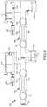
- FIG. 3is a schematic view of heat pump system 100 .
- heat pump system 100includes a fresh food regenerator 180 with a first caloric material stage 182 and a second caloric material stage 184 .
- First and second caloric material stages 182 , 184 of fresh food regenerator 180include a magneto-caloric material that exhibit the magneto-caloric effect.
- first caloric material stage 182 of fresh food regenerator 180may increase in temperature and thereby heat transfer fluid flowing through first caloric material stage 182 .
- Heat pump system 100may include a motor, such as motor 102 , coupled to fresh food regenerator 180 and/or magnet 186 to provide relative motion between fresh food regenerator 180 and magnet 186 .
- the motormay be operable to sequentially move first and second caloric material stages 182 , 184 of fresh food regenerator 180 into and out of the magnetic field from magnet 186 .
- Heat pump system 100also includes a freezer regenerator 190 with a first caloric material stage 192 and a second caloric material stage 194 .
- First and second caloric material stages 192 , 194 of freezer regenerator 190include a magneto-caloric material that exhibit the magneto-caloric effect.
- first caloric material stage 192 of freezer regenerator 190may increase in temperature and thereby heat transfer fluid flowing through first caloric material stage 192 .
- Heat pump system 100may include a motor, such as motor 102 , coupled to freezer regenerator 190 and/or magnet 196 to provide relative motion between freezer regenerator 190 and magnet 196 .
- the motormay be operable to sequentially move first and second caloric material stages 192 , 194 of freezer regenerator 190 into and out of the magnetic field from magnet 196 .
- the one or more magneto-caloric material(s) in fresh food regenerator 180 and freezer regenerator 190may be different.
- the magneto-caloric materials in fresh food regenerator 180may be selected to cool fresh-food compartment 14 , e.g., to about thirty-two degrees Fahrenheit (32° F.).
- the magneto-caloric materials in freezer regenerator 190may be selected to cool freezer compartment 18 , e.g., to about negative ten degrees Fahrenheit ( ⁇ 10° F.).
- each of fresh food regenerator 180 and freezer regenerator 190may include three (or more) caloric material stages in alternative example embodiments.
- heat pump system 100includes a first pair of diverter valves 142 coupled to fresh food working fluid circuit 140 and a second pair of diverter valves 152 coupled to freezer working fluid circuit 150 .
- First and second diverter valves 142 , 152may be coupled to motor 102 such that motor 102 is operable to adjust first and second diverter valves 142 , 152 , e.g., in a synchronized manner with the relative motion between fresh food regenerator 180 and magnet 186 and/or with the relative motion between freezer regenerator 190 and magnet 196 .
- the first diverter valves 142are configured for selectively changing a flow direction of the heat transfer fluid within fresh food working fluid circuit 140 through first and second caloric material stages 182 , 184 of fresh food regenerator 180 .
- a first actuation flow path through first diverter valves 142is shown with black lines in FIG. 3
- a second actuation flow path through first diverter valves 142is shown with dashed lines in FIG. 3 .
- first diverter valves 142may flow the heat transfer fluid from hot side reservoir 160 through either the first and second caloric material stages 182 , 184 of fresh food regenerator 180 , e.g., depending upon which one of the first and second caloric material stages 182 , 184 of fresh food regenerator 180 is within the magnetic field of magnet 186 .
- first diverter valves 142may be shifted to the first actuation flow path when first caloric material stage 182 of fresh food regenerator 180 is positioned outside of the magnetic field of magnet 186 and second caloric material stage 184 of fresh food regenerator 180 is positioned within the magnetic field of magnet 186 .
- first diverter valves 142may be shifted to the second actuation flow path when first caloric material stage 182 of fresh food regenerator 180 is positioned within the magnetic field of magnet 186 and second caloric material stage 184 of fresh food regenerator 180 is positioned outside of the magnetic field of magnet 186 .
- the second diverter valves 152are configured for selectively changing a flow direction of the heat transfer fluid within freezer working fluid circuit 150 through first and second caloric material stages 192 , 194 of freezer regenerator 190 .
- a first actuation flow path through second diverter valves 152is shown with black lines in FIG. 3
- a second actuation flow path through second diverter valves 152is shown with dashed lines in FIG. 3 .
- second diverter valves 152may flow the heat transfer fluid from fresh food reservoir 170 through either the first and second caloric material stages 192 , 194 of freezer regenerator 190 , e.g., depending upon which one of the first and second caloric material stages 192 , 194 of fresh freezer regenerator 190 is within the magnetic field of magnet 196 .
- second diverter valves 152may be shifted to the first actuation flow path when first caloric material stage 192 of freezer regenerator 190 is positioned outside of the magnetic field of magnet 196 and second caloric material stage 194 of freezer regenerator 190 is positioned within the magnetic field of magnet 196 .
- second diverter valves 152may be shifted to the second actuation flow path when first caloric material stage 192 of freezer regenerator 190 is positioned within the magnetic field of magnet 196 and second caloric material stage 194 of freezer regenerator 190 is positioned outside of the magnetic field of magnet 196 .
- a liquid-liquid heat exchanger 172is connected to fresh food working fluid circuit 140 .
- the heat transfer fluid within fresh food working fluid circuit 140flows through liquid-liquid heat exchanger 172 .
- liquid-liquid heat exchanger 172may be positioned downstream of fresh food heat exchanger 120 and upstream of fresh food regenerator 180 on fresh food working fluid circuit 140 .
- Liquid-liquid heat exchanger 172is thermally coupled to fresh food reservoir 170 .
- liquid-liquid heat exchanger 172may be submerged within the heat transfer fluid of freezer working fluid circuit 150 in fresh food reservoir 170 .
- fresh food working fluid circuit 140connects hot side heat exchanger 110 , fresh food heat exchanger 120 , hot side reservoir 160 and fresh food regenerator 180 .
- heat transfer fluidmay flow between hot side heat exchanger 110 , fresh food heat exchanger 120 , hot side reservoir 160 and fresh food regenerator 180 through fresh food working fluid circuit 140 .
- a pump 104may urge the heat transfer fluid in fresh food working fluid circuit 140 to flow between hot side heat exchanger 110 , fresh food heat exchanger 120 , hot side reservoir 160 and fresh food regenerator 180 , as described in greater detail below.
- Arrowsare provided on fresh food working fluid circuit 140 in FIG. 3 to show the direction of heat transfer fluid flow through fresh food working fluid circuit 140 .
- the heat transfer fluid within fresh food heat exchanger 120receives heat from fresh-food compartment 14 thereby cooling contents of fresh-food compartment 14 .
- the air in fresh-food compartment 14may reject heat to the heat transfer fluid within fresh food heat exchanger 120 .
- the heat transfer fluidflows out of fresh food heat exchanger 120 by fresh food working fluid circuit 140 to liquid-liquid heat exchanger 172 thermally coupled to fresh food reservoir 170 .
- the working fluid from fresh food heat exchanger 120 within liquid-liquid heat exchanger 172receives heat from the heat transfer fluid of freezer working fluid circuit 150 within fresh food reservoir 170 .
- the heat transfer fluid from fresh food heat exchanger 120receives additional heat from the heat transfer fluid of freezer working fluid circuit 150 within fresh food reservoir 170 .
- the heat transfer fluidthen flows out of liquid-liquid heat exchanger 172 via fresh food working fluid circuit 140 to fresh food regenerator 180 .
- the heat transfer fluid from liquid-liquid heat exchanger 172may flow into the one of first and second caloric material stages 182 , 184 of fresh food regenerator 180 that is within the magnetic field of magnet 186 .
- the heat transfer fluid from liquid-liquid heat exchanger 172 flowing through fresh food regenerator 180receives additional heat from magneto-caloric material (MCM) in fresh food regenerator 180 .
- MCMmagneto-caloric material
- the heat transfer fluidcarries this heat through fresh food working fluid circuit 140 to hot side heat exchanger 110 .
- hot side heat exchanger 110the heat in the transfer fluid is released to the environment, machinery compartment 40 , and/or other location external to refrigeration compartments 30 .
- hot side reservoir 160From hot side heat exchanger 110 , the heat transfer fluid flows into hot side reservoir 160 .
- the heat transfer fluid in fresh food working fluid circuit 140may reject heat to the environment, machinery compartment 40 , etc. due to the placement of hot side reservoir 160 , e.g., within machinery compartment 40 .
- hot side reservoir 160may assist with tight temperature control of heat transfer fluid returning to fresh food regenerator 180 .
- the heat transfer fluidreturns by fresh food working fluid circuit 140 to fresh food regenerator 180 .
- the heat transfer fluid from hot side reservoir 160may flow into the one of first and second caloric material stages 182 , 184 of fresh food regenerator 180 that is outside of the magnetic field of magnet 186 .
- the heat transfer fluid from hot side reservoir 160 flowing through fresh food regenerator 180rejects heat to magneto-caloric material (MCM) in fresh food regenerator 180 .
- MCMmagneto-caloric material
- the now colder heat transfer fluidflows through fresh food working fluid circuit 140 to fresh food heat exchanger 120 to receive heat from fresh-food compartment 14 and repeat the cycle as just described.
- freezer working fluid circuit 150connects freezer heat exchanger 130 , fresh food reservoir 170 and freezer regenerator 190 .
- heat transfer fluidmay flow between freezer heat exchanger 130 , fresh food reservoir 170 and freezer regenerator 190 through freezer working fluid circuit 150 .
- pump 104may urge the heat transfer fluid in freezer working fluid circuit 150 to flow between freezer heat exchanger 130 , fresh food reservoir 170 and freezer regenerator 190 , as described in greater detail below.
- Arrowsare provided on freezer working fluid circuit 150 in FIG. 3 to show the direction of heat transfer fluid flow through freezer working fluid circuit 150 .
- freezer heat exchanger 130receives heat from freezer compartment 18 thereby cooling contents of fresh-food compartment 14 .
- freezer compartment 18may reject heat to the heat transfer fluid within freezer heat exchanger 130 .
- the heat transfer fluidflows out of freezer heat exchanger 130 by freezer working fluid circuit 150 to freezer regenerator 190 .
- the heat transfer fluid from freezer heat exchanger 130may flow into the one of first and second caloric material stages 192 , 194 of freezer regenerator 190 that is within the magnetic field of magnet 196 .
- the heat transfer fluid from freezer heat exchanger 130 flowing through freezer regenerator 190receives additional heat from magneto-caloric material (MCM) in freezer regenerator 190 .
- MCMmagneto-caloric material
- the heat transfer fluidcarries this heat through freezer working fluid circuit 150 to fresh food reservoir 170 .
- fresh food reservoir 170the heat in the transfer fluid is rejected to the working fluid in fresh food working fluid circuit 140 via liquid-liquid heat exchanger 172 and/or to the air within fresh-food compartment 14 due to the placement of fresh food reservoir 170 within fresh-food compartment 14 .
- fresh food reservoir 170may assist with tight temperature control of heat transfer fluid returning to freezer regenerator 190 .
- the heat transfer fluidthen flows out of fresh food reservoir 170 by freezer working fluid circuit 150 to back to freezer regenerator 190 .
- the heat transfer fluid from fresh food reservoir 170may flow into the one of first and second caloric material stages 192 , 194 of freezer regenerator 190 that is outside of the magnetic field of magnet 196 .
- the heat transfer fluid from fresh food reservoir 170 flowing through freezer regenerator 190rejects heat to magneto-caloric material (MCM) in freezer regenerator 190 .
- MCMmagneto-caloric material
- the now colder heat transfer fluidflows through freezer working fluid circuit 150 to freezer heat exchanger 130 to receive heat from freezer compartment 18 and repeat the cycle as just described.
- heat pump system 100The flow of heat transfer fluid in heat pump system 100 described above is provided by way of example only. Other configurations of heat pump system 100 may be used as well.
- the illustrated lines of fresh food and freezer working fluid circuits 140 , 150provide fluid communication between the various components of heat pump system 100 in FIG. 3 but other heat transfer fluid recirculation loops with different lines and connections may also be employed. Still other configurations of heat pump system 100 may be used as well.
- hot side reservoir 160is coupled to fresh food working fluid circuit 140 and is positioned outside of refrigeration compartments 30 , e.g., within machinery compartment 40 .
- Hot side reservoir 160is sized for containing a volume of the heat transfer fluid of fresh food working fluid circuit 140 .
- the volume of the heat transfer fluid from fresh food working fluid circuit 140 within hot side reservoir 160may assist with providing leak resilience and a simple system, and the size of hot side reservoir 160 may be selected to provide such benefits.
- hot side reservoir 160may be sized to hold no less than one hundred and fifty milliliters (150 mL) of heat transfer fluid.
- hot side reservoir 160may be sized to hold no less than five hundred milliliters (500 mL) of heat transfer fluid.
- Such sizingis advantageous, e.g., because the heat transfer fluid within hot side reservoir 160 may dwell within machinery compartment 40 and thereby maintain a suitable temperature and/or may provide a suitable area for catching leaking fluid.
- Hot side reservoir 160may be positioned below one or both of first diverter valves 142 .
- hot side reservoir 160may be positioned below first diverter valves 142 to recapture leakage of the heat transfer fluid from first diverter valves 142 .
- first diverter valves 142 , hot side reservoir 160 and/or fresh food regenerator 180may be positioned within a hermetic shell 164 ( FIG. 2 ).
- the inner surface of hermetic shell 164may form reservoir 160 .
- fresh food reservoir 170is coupled to freezer working fluid circuit 150 and is positioned within of fresh-food compartment 14 .
- Fresh food reservoir 170is sized for containing a volume of the heat transfer fluid of freezer working fluid circuit 150 .
- the volume of the heat transfer fluid from freezer working fluid circuit 150 within fresh food reservoir 170may assist with providing leak resilience and a simple system, and the size of fresh food reservoir 170 may be selected to provide such benefits.
- fresh food reservoir 170may be sized to hold no less than one hundred and fifty milliliters (150 mL) of heat transfer fluid.
- fresh food reservoir 170may be sized to hold no less than five hundred milliliters (500 mL) of heat transfer fluid.
- Such sizingis advantageous, e.g., because the heat transfer fluid within fresh food reservoir 170 may dwell within fresh-food compartment 14 and thereby maintain a suitable temperature and/or may provide a suitable area for catching leaking fluid.
- Fresh food reservoir 170may be positioned below one or both of second diverter valves 152 .
- fresh food reservoir 170may be positioned below second diverter valves 152 to recapture leakage of the heat transfer fluid from second diverter valves 152 .
- second diverter valves 152 , fresh food reservoir 170 and/or freezer regenerator 190may be positioned within a hermetic shell 174 ( FIG. 2 ).
- the inner surface of hermetic shell 174may form fresh food reservoir 170 .
- pump 104may be connected to fresh food working fluid circuit 140 and freezer working fluid circuit 150 .
- Pump 104is operable to flow heat transfer fluid through fresh food working fluid circuit 140 and to flow heat transfer fluid through freezer working fluid circuit 150 .
- Pump 104may include a first piston 144 coupled to fresh food working fluid circuit 140 and a second piston 154 coupled to freezer working fluid circuit 150 .
- First and second pistons 144 , 154may be connected to motor 102 such that first and second pistons 144 , 154 are drivable by a common motor, e.g., and such that reciprocation of first and second pistons 144 , 154 is synchronized.
- first and second pistons 144 , 154may be driven by separate motors, e.g., such that first and second pistons 144 , 154 may reciprocate independently.
- First piston 144may be positioned within a double-acting cylinder 146 connected to fresh food working fluid circuit 140
- second piston 154may be positioned within a double-acting cylinder 156 connected to freezer working fluid circuit 150 .
- Double-acting cylinders 146 , 156may allow efficient pumping of heat transfer fluid through fresh food and freezer working fluid circuits 140 , 150 .
- pump 104may include single-acting cylinders or another positive displacement pump design.
- FIG. 4is a schematic view of a heat pump system 200 according to another example embodiment of the present subject matter.
- Heat pump system 200may be used in or with any suitable appliance, such as refrigerator appliance 100 .
- heat pump system 200is described in greater detail below in the context of refrigerator appliance 100 .
- Heat pump system 200include numerous common components with heat pump system 100 ( FIG. 3 ) and operates in the same or similar manner. However, heat pump system 200 includes additional components as described below.
- heat pump system 200includes a first flow damper 202 coupled to fresh food working fluid circuit 140 and a second flow damper 204 coupled to freezer working fluid circuit 150 .
- First flow damper 202is configured to dampen pressure and flow spikes of the heat transfer fluid in fresh food working fluid circuit 140 .
- second flow damper 204is configured to dampen pressure and flow spikes of the heat transfer fluid in freezer working fluid circuit 150 .
- first and second flow dampers 202 , 204may elastically move or deform to regulate and smooth out the flow profile of working fluid, e.g., which will have a slight pulsing quality without first and second flow dampers 202 , 204 .
- first and second flow dampers 202 , 204may be a spring-loaded piston (as shown in FIG. 4 ), a flexible tube, a flexible diaphragm, etc.
- FIG. 5is a schematic view of a heat pump system 300 according to another example embodiment of the present subject matter.
- Heat pump system 300may be used in or with any suitable appliance, such as refrigerator appliance 100 .
- heat pump system 300is described in greater detail below in the context of refrigerator appliance 100 .
- Heat pump system 300include numerous common components with heat pump system 100 ( FIG. 3 ) and heat pump system 200 ( FIG. 4 ) and operates in the same or similar manner.
- heat pump system 300includes additional components as described below.
- a tray 302 of hot side reservoir 160extends below first diverter valves 142 to recover leaks from first diverter valves 142 .
- a tray 304 of fresh food reservoir 170extends below second diverter valves 152 to recover leaks from second diverter valves 152 .
- Such trays 302 , 304may allow first and second diverter valves 142 , 152 to permit small leaks, e.g., such that first and second diverter valves 142 , 152 may have lower frictional losses (and lower sealing pressure) compared to diverter valves that are designed to not leak.
- Heat pump system 300also includes reversing valves 306 .
- Reversing valves 306may be actuated to reverse the direction of working fluid flow through fresh food and freezer regenerators 180 , 190 for defrost.
- reversing valves 306may allow operation of heat pump system 300 in reverse from that described above.
Landscapes
- Engineering & Computer Science (AREA)
- Physics & Mathematics (AREA)
- Mechanical Engineering (AREA)
- Thermal Sciences (AREA)
- General Engineering & Computer Science (AREA)
- Chemical & Material Sciences (AREA)
- Combustion & Propulsion (AREA)
- Devices That Are Associated With Refrigeration Equipment (AREA)
Abstract
Description
The present subject matter relates generally to caloric heat pump hydraulic systems.
Conventional refrigeration technology typically utilizes a heat pump that relies on compression and expansion of a fluid refrigerant to receive and reject heat in a cyclic manner so as to effect a desired temperature change or transfer heat energy from one location to another. This cycle can be used to receive heat from a refrigeration compartment and reject such heat to the environment or a location that is external to the compartment. Other applications include air conditioning of residential or commercial structures. A variety of different fluid refrigerants have been developed that can be used with the heat pump in such systems.
While improvements have been made to such heat pump systems that rely on the compression of fluid refrigerant, at best such can still only operate at about forty-five percent or less of the maximum theoretical Carnot cycle efficiency. Also, some fluid refrigerants have been discontinued due to environmental concerns. The range of ambient temperatures over which certain refrigerant-based systems can operate may be impractical for certain locations. Other challenges with heat pumps that use a fluid refrigerant exist as well.
Magneto-caloric materials (MCMs), i.e. materials that exhibit the magneto-caloric effect, provide a potential alternative to fluid refrigerants for heat pump applications. In general, the magnetic moments of MCMs become more ordered under an increasing, externally applied magnetic field and cause the MCMs to generate heat. Conversely, decreasing the externally applied magnetic field allows the magnetic moments of the MCMs to become more disordered and allow the MCMs to absorb heat. Some MCMs exhibit the opposite behavior, i.e. generating heat when the magnetic field is removed (which are sometimes referred to as para-magneto-caloric material but both types are referred to collectively herein as magneto-caloric material or MCM). The theoretical Carnot cycle efficiency of a refrigeration cycle based on an MCMs can be significantly higher than for a comparable refrigeration cycle based on a fluid refrigerant. As such, a heat pump system that can effectively use an MCM would be useful.
Challenges exist to the practical and cost competitive use of an MCM, however. In addition to the development of suitable MCMs, equipment that can attractively utilize an MCM is still needed. Currently proposed equipment may require relatively large and expensive magnets, may be impractical for use in e.g., appliance refrigeration, and may not otherwise operate with enough efficiency to justify capital cost.
Accordingly, a heat pump system that can address certain challenges, such as those identified above, would be useful. Such a heat pump system that can also be used in a refrigerator appliance would also be useful.
Aspects and advantages of the invention will be set forth in part in the following description, or may be apparent from the description, or may be learned through practice of the invention.
In an example embodiment, a refrigerator appliance includes a cabinet defining a fresh food chamber and a freezer chamber. A hot side heat exchanger is positioned outside of the fresh food chamber and the freezer chamber of the cabinet. A fresh food cold side heat exchanger is positioned within the cabinet at the fresh food chamber. The fresh food chamber is chillable with air from the fresh food cold side heat exchanger. A freezer cold side heat exchanger is positioned within the cabinet at the freezer chamber. The freezer chamber is chillable with air from the freezer cold side heat exchanger. A fresh food regenerator includes a first caloric material stage and a second caloric material stage. A freezer regenerator includes a first caloric material stage and a second caloric material stage. The first and second caloric material stages of the freezer regenerator are separate from the first and second caloric material stages of the fresh food regenerator. A fresh food working fluid circuit couples the hot side heat exchanger, the fresh food cold side heat exchanger and the fresh food regenerator such that a first working fluid is flowable through the hot side heat exchanger, the fresh food cold side heat exchanger and the fresh food regenerator via the fresh food working fluid circuit. A first pair of diverter valves is coupled to the fresh food working fluid circuit. The first pair of diverter valves is configured for selectively changing a flow direction of the first working fluid through the first caloric material stage and the second caloric material stage of the fresh food regenerator. A hot side reservoir is coupled to the fresh food working fluid circuit. The hot side reservoir is sized for containing a volume of the first working fluid. The hot side reservoir is positioned outside of the fresh food chamber and the freezer chamber of the cabinet. The hot side reservoir is positioned below one or both of the first pair of diverter valves. A freezer working fluid circuit couples the freezer cold side heat exchanger and the freezer regenerator such that a second working fluid is flowable through the freezer cold side heat exchanger and the freezer regenerator via the freezer working fluid circuit. A second pair of diverter valves is coupled to the freezer working fluid circuit. The second pair of diverter valves is configured for selectively changing a flow direction of the second working fluid through the first caloric material stage and the second caloric material stage of the freezer regenerator. A fresh food cold side reservoir is coupled to the freezer working fluid circuit. The fresh food cold side reservoir is sized for containing a volume of the second working fluid. The fresh food cold side reservoir is positioned within the cabinet at the fresh food chamber. The fresh food cold side reservoir is positioned below one or both of the second pair of diverter valves. A liquid-liquid heat exchanger is coupled to the fresh food working fluid circuit such that the first working fluid is flowable through the liquid-liquid heat exchanger. The liquid-liquid heat exchanger is positioned at the fresh food cold side reservoir such the liquid-liquid heat exchanger is configured for exchanging heat between the first working fluid in the liquid-liquid heat exchanger and the second working fluid in the fresh food cold side reservoir.
These and other features, aspects and advantages of the present invention will become better understood with reference to the following description and appended claims. The accompanying drawings, which are incorporated in and constitute a part of this specification, illustrate embodiments of the invention and, together with the description, serve to explain the principles of the invention.
A full and enabling disclosure of the present invention, including the best mode thereof, directed to one of ordinary skill in the art, is set forth in the specification, which makes reference to the appended figures.
Reference now will be made in detail to embodiments of the invention, one or more examples of which are illustrated in the drawings. Each example is provided by way of explanation of the invention, not limitation of the invention. In fact, it will be apparent to those skilled in the art that various modifications and variations can be made in the present invention without departing from the scope or spirit of the invention. For instance, features illustrated or described as part of one embodiment can be used with another embodiment to yield a still further embodiment. Thus, it is intended that the present invention covers such modifications and variations as come within the scope of the appended claims and their equivalents.
The present subject matter is directed to caloric heat pump systems for heating or cooling an appliance, such as a refrigerator appliance. While described in greater detail below in the context of a magneto-caloric heat pump system, one of skill in the art using the teachings herein will recognize that other suitable caloric materials may be used in a similar manner to heat or cool an appliance, i.e., apply a field, move heat, remove the field, move heat. For example, electro-caloric material heats up and cools down within increasing and decreasing electric fields. As another example, elasto-caloric material heats up and cools down when exposed to increasing and decreasing mechanical strain. As yet another example, baro-caloric material heats up and cools down when exposed to increasing and decreasing pressure. Such materials and other similar caloric materials may be used in place of or in addition to the magneto-caloric material described below to heat or cool fluid within an appliance. Thus, caloric material is used broadly herein to encompass materials that undergo heating or cooling when exposed to a changing field from a field generator, where the field generator may be a magnet, an electric field generator, an actuator for applying mechanical stress or pressure, etc.
Referring now toFIG. 1 , an example embodiment of arefrigerator appliance 10 is depicted as an upright refrigerator having a cabinet or casing12 that defines a number of internal storage compartments or chilled chambers. In particular,refrigerator appliance 10 includes upper fresh-food compartments 14 havingdoors 16 andlower freezer compartment 18 havingupper drawer 20 andlower drawer 22.Drawers freezer compartment 18 on suitable slide mechanisms.Refrigerator 10 is provided by way of example only. Other configurations for a refrigerator appliance may be used as well including appliances with only freezer compartments, only chilled compartments, or other combinations thereof different from that shown inFIG. 1 . In addition, the heat pump and heat pump system of the present disclosure is not limited to refrigerator appliances and may be used in other applications as well such as e.g., air-conditioning, electronics cooling devices, and others. Thus, it should be understood that while the use of a heat pump and heat pump system to provide cooling within a refrigerator is provided by way of example herein, the present disclosure may also be used to provide for heating applications as well.
A fresh food coldside heat exchanger 120 is positioned in fresh-food compartment 14 for the removal of heat therefrom. Heat transfer fluid such as e.g., an aqueous solution, flowing within freshfood heat exchanger 120 receives heat from fresh-food compartment 14 thereby cooling contents of fresh-food compartment 14. In particular, air around freshfood heat exchanger 120 may be circulated (e.g., with a fresh food fan122) within fresh-food compartment 14 such that the air from freshfood heat exchanger 120 cools fresh-food compartment 14.Fresh food fan 122 may thus be used to create a flow of air across freshfood heat exchanger 120 and thereby improve the rate of heat transfer. As may be seen from the above, operation ofheat pump system 100 andfresh food fan 122 allows freshfood heat exchanger 120 to cool fresh-food compartment 14, e.g., to about thirty-two degrees Fahrenheit (32° F.).
As may be seen inFIG. 2 ,heat pump system 100 also has a freezer coldside heat exchanger 130.Freezer heat exchanger 130 may operate in parallel with freshfood heat exchanger 120. Thus, e.g.,freezer heat exchanger 130 is positioned infreezer compartment 18 for the removal of heat therefrom. Heat transfer fluid such as e.g., an aqueous solution, flowing withinfreezer heat exchanger 130 receives heat fromfreezer compartment 18 thereby cooling contents offreezer compartment 18. In particular, air aroundfreezer heat exchanger 130 may be circulated (e.g., with a freezer fan132) withinfreezer compartment 18 such that the air fromfreezer heat exchanger 130 coolsfreezer compartment 18.Freezer fan 132 may thus be used to create a flow of air acrossfreezer heat exchanger 130 and thereby improve the rate of heat transfer. As may be seen from the above, operation ofheat pump system 100 andfreezer fan 132 allow chilled air fromfreezer heat exchanger 130 tocool freezer compartment 18, e.g., to about negative ten degrees Fahrenheit (−10° F.).
A fresh food workingfluid circuit 140 connects hotside heat exchanger 110, freshfood heat exchanger 120 and other components ofheat pump system 100, including ahot side reservoir 160. Thus, the heat transfer fluid within fresh food workingfluid circuit 140 may flow between hotside heat exchanger 110, freshfood heat exchanger 120,hot side reservoir 160, etc. within fresh food workingfluid circuit 140. Fresh food workingfluid circuit 140 may include suitable conduits for fluidly connecting components, such as pipes, tubes, lines, etc. in order to allow the heat transfer fluid to flow between, inter alia, hotside heat exchanger 110, freshfood heat exchanger 120 andhot side reservoir 160.
A freezer workingfluid circuit 150 connectsfreezer heat exchanger 130 and other components ofheat pump system 100, including a fresh foodcold side reservoir 170. Thus, the heat transfer fluid within freezer workingfluid circuit 150 may flow betweenfreezer heat exchanger 130 andfresh food reservoir 170, etc. within freezer workingfluid circuit 150. Freezer workingfluid circuit 150 may include suitable conduits for fluidly connecting components, such as pipes, tubes, lines, etc. in order to allow the heat transfer fluid to flow between, inter alia,freezer heat exchanger 130 andfresh food reservoir 170. Freezer workingfluid circuit 150 may be separate from fresh food workingfluid circuit 140, e.g., such that the heat transfer fluid within fresh food workingfluid circuit 140 does not mix with the heat transfer fluid within freezer workingfluid circuit 150.
The one or more magneto-caloric material(s) infresh food regenerator 180 andfreezer regenerator 190 may be different. For example, the magneto-caloric materials infresh food regenerator 180 may be selected to cool fresh-food compartment 14, e.g., to about thirty-two degrees Fahrenheit (32° F.). Conversely, the magneto-caloric materials infreezer regenerator 190 may be selected tocool freezer compartment 18, e.g., to about negative ten degrees Fahrenheit (−10° F.). In addition, while only shown with two caloric material stages inFIG. 3 , it will be understood that each offresh food regenerator 180 andfreezer regenerator 190 may include three (or more) caloric material stages in alternative example embodiments.
As shown inFIG. 3 ,heat pump system 100 includes a first pair ofdiverter valves 142 coupled to fresh food workingfluid circuit 140 and a second pair ofdiverter valves 152 coupled to freezer workingfluid circuit 150. First andsecond diverter valves motor 102 such thatmotor 102 is operable to adjust first andsecond diverter valves fresh food regenerator 180 andmagnet 186 and/or with the relative motion betweenfreezer regenerator 190 andmagnet 196.
Thefirst diverter valves 142 are configured for selectively changing a flow direction of the heat transfer fluid within fresh food workingfluid circuit 140 through first and second caloric material stages182,184 offresh food regenerator 180. In particular, a first actuation flow path throughfirst diverter valves 142 is shown with black lines inFIG. 3 , and a second actuation flow path throughfirst diverter valves 142 is shown with dashed lines inFIG. 3 . As may be seen from the above,first diverter valves 142 may flow the heat transfer fluid fromhot side reservoir 160 through either the first and second caloric material stages182,184 offresh food regenerator 180, e.g., depending upon which one of the first and second caloric material stages182,184 offresh food regenerator 180 is within the magnetic field ofmagnet 186. In particular,first diverter valves 142 may be shifted to the first actuation flow path when firstcaloric material stage 182 offresh food regenerator 180 is positioned outside of the magnetic field ofmagnet 186 and secondcaloric material stage 184 offresh food regenerator 180 is positioned within the magnetic field ofmagnet 186. Conversely,first diverter valves 142 may be shifted to the second actuation flow path when firstcaloric material stage 182 offresh food regenerator 180 is positioned within the magnetic field ofmagnet 186 and secondcaloric material stage 184 offresh food regenerator 180 is positioned outside of the magnetic field ofmagnet 186.
In a similar manner, thesecond diverter valves 152 are configured for selectively changing a flow direction of the heat transfer fluid within freezer workingfluid circuit 150 through first and second caloric material stages192,194 offreezer regenerator 190. In particular, a first actuation flow path throughsecond diverter valves 152 is shown with black lines inFIG. 3 , and a second actuation flow path throughsecond diverter valves 152 is shown with dashed lines inFIG. 3 . As may be seen from the above,second diverter valves 152 may flow the heat transfer fluid fromfresh food reservoir 170 through either the first and second caloric material stages192,194 offreezer regenerator 190, e.g., depending upon which one of the first and second caloric material stages192,194 offresh freezer regenerator 190 is within the magnetic field ofmagnet 196. In particular,second diverter valves 152 may be shifted to the first actuation flow path when firstcaloric material stage 192 offreezer regenerator 190 is positioned outside of the magnetic field ofmagnet 196 and secondcaloric material stage 194 offreezer regenerator 190 is positioned within the magnetic field ofmagnet 196. Conversely,second diverter valves 152 may be shifted to the second actuation flow path when firstcaloric material stage 192 offreezer regenerator 190 is positioned within the magnetic field ofmagnet 196 and secondcaloric material stage 194 offreezer regenerator 190 is positioned outside of the magnetic field ofmagnet 196.
A liquid-liquid heat exchanger 172 is connected to fresh food workingfluid circuit 140. Thus, the heat transfer fluid within fresh food workingfluid circuit 140 flows through liquid-liquid heat exchanger 172. As an example, liquid-liquid heat exchanger 172 may be positioned downstream of freshfood heat exchanger 120 and upstream offresh food regenerator 180 on fresh food workingfluid circuit 140. Liquid-liquid heat exchanger 172 is thermally coupled tofresh food reservoir 170. For example, liquid-liquid heat exchanger 172 may be submerged within the heat transfer fluid of freezer workingfluid circuit 150 infresh food reservoir 170.
Working fluid flow through fresh food workingfluid circuit 140 will now be described in greater detail below. As may be seen inFIG. 3 , fresh food workingfluid circuit 140 connects hotside heat exchanger 110, freshfood heat exchanger 120,hot side reservoir 160 andfresh food regenerator 180. Thus, heat transfer fluid may flow between hotside heat exchanger 110, freshfood heat exchanger 120,hot side reservoir 160 andfresh food regenerator 180 through fresh food workingfluid circuit 140. In particular, apump 104 may urge the heat transfer fluid in fresh food workingfluid circuit 140 to flow between hotside heat exchanger 110, freshfood heat exchanger 120,hot side reservoir 160 andfresh food regenerator 180, as described in greater detail below. Arrows are provided on fresh food workingfluid circuit 140 inFIG. 3 to show the direction of heat transfer fluid flow through fresh food workingfluid circuit 140.
As noted above, the heat transfer fluid within freshfood heat exchanger 120 receives heat from fresh-food compartment 14 thereby cooling contents of fresh-food compartment 14. Thus, the air in fresh-food compartment 14 may reject heat to the heat transfer fluid within freshfood heat exchanger 120. The heat transfer fluid flows out of freshfood heat exchanger 120 by fresh food workingfluid circuit 140 to liquid-liquid heat exchanger 172 thermally coupled tofresh food reservoir 170. The working fluid from freshfood heat exchanger 120 within liquid-liquid heat exchanger 172 receives heat from the heat transfer fluid of freezer workingfluid circuit 150 withinfresh food reservoir 170. Thus, the heat transfer fluid from freshfood heat exchanger 120 receives additional heat from the heat transfer fluid of freezer workingfluid circuit 150 withinfresh food reservoir 170.
The heat transfer fluid then flows out of liquid-liquid heat exchanger 172 via fresh food workingfluid circuit 140 tofresh food regenerator 180. In particular, the heat transfer fluid from liquid-liquid heat exchanger 172 may flow into the one of first and second caloric material stages182,184 offresh food regenerator 180 that is within the magnetic field ofmagnet 186. Thus, the heat transfer fluid from liquid-liquid heat exchanger 172 flowing throughfresh food regenerator 180 receives additional heat from magneto-caloric material (MCM) infresh food regenerator 180. The heat transfer fluid carries this heat through fresh food workingfluid circuit 140 to hotside heat exchanger 110. In hotside heat exchanger 110, the heat in the transfer fluid is released to the environment,machinery compartment 40, and/or other location external to refrigeration compartments30.
From hotside heat exchanger 110, the heat transfer fluid flows intohot side reservoir 160. Withinhot side reservoir 160, the heat transfer fluid in fresh food workingfluid circuit 140 may reject heat to the environment,machinery compartment 40, etc. due to the placement ofhot side reservoir 160, e.g., withinmachinery compartment 40. Thus,hot side reservoir 160 may assist with tight temperature control of heat transfer fluid returning tofresh food regenerator 180.
Fromhot side reservoir 160, the heat transfer fluid returns by fresh food workingfluid circuit 140 tofresh food regenerator 180. In particular, the heat transfer fluid fromhot side reservoir 160 may flow into the one of first and second caloric material stages182,184 offresh food regenerator 180 that is outside of the magnetic field ofmagnet 186. Thus, the heat transfer fluid fromhot side reservoir 160 flowing throughfresh food regenerator 180 rejects heat to magneto-caloric material (MCM) infresh food regenerator 180. The now colder heat transfer fluid flows through fresh food workingfluid circuit 140 to freshfood heat exchanger 120 to receive heat from fresh-food compartment 14 and repeat the cycle as just described.
Working fluid flow through freezer workingfluid circuit 150 is similar to that described above for fresh food workingfluid circuit 140 and will now be described in greater detail below. As may be seen inFIG. 3 , freezer workingfluid circuit 150 connectsfreezer heat exchanger 130,fresh food reservoir 170 andfreezer regenerator 190. Thus, heat transfer fluid may flow betweenfreezer heat exchanger 130,fresh food reservoir 170 andfreezer regenerator 190 through freezer workingfluid circuit 150. In particular, pump104 may urge the heat transfer fluid in freezer workingfluid circuit 150 to flow betweenfreezer heat exchanger 130,fresh food reservoir 170 andfreezer regenerator 190, as described in greater detail below. Arrows are provided on freezer workingfluid circuit 150 inFIG. 3 to show the direction of heat transfer fluid flow through freezer workingfluid circuit 150.
As noted above, the heat transfer fluid withinfreezer heat exchanger 130 receives heat fromfreezer compartment 18 thereby cooling contents of fresh-food compartment 14. Thus, the air infreezer compartment 18 may reject heat to the heat transfer fluid withinfreezer heat exchanger 130. The heat transfer fluid flows out offreezer heat exchanger 130 by freezer workingfluid circuit 150 tofreezer regenerator 190. In particular, the heat transfer fluid fromfreezer heat exchanger 130 may flow into the one of first and second caloric material stages192,194 offreezer regenerator 190 that is within the magnetic field ofmagnet 196. Thus, the heat transfer fluid fromfreezer heat exchanger 130 flowing throughfreezer regenerator 190 receives additional heat from magneto-caloric material (MCM) infreezer regenerator 190. The heat transfer fluid carries this heat through freezer workingfluid circuit 150 tofresh food reservoir 170. Infresh food reservoir 170, the heat in the transfer fluid is rejected to the working fluid in fresh food workingfluid circuit 140 via liquid-liquid heat exchanger 172 and/or to the air within fresh-food compartment 14 due to the placement offresh food reservoir 170 within fresh-food compartment 14. Thus,fresh food reservoir 170 may assist with tight temperature control of heat transfer fluid returning tofreezer regenerator 190.
The heat transfer fluid then flows out offresh food reservoir 170 by freezer workingfluid circuit 150 to back tofreezer regenerator 190. In particular, the heat transfer fluid fromfresh food reservoir 170 may flow into the one of first and second caloric material stages192,194 offreezer regenerator 190 that is outside of the magnetic field ofmagnet 196. Thus, the heat transfer fluid fromfresh food reservoir 170 flowing throughfreezer regenerator 190 rejects heat to magneto-caloric material (MCM) infreezer regenerator 190. The now colder heat transfer fluid flows through freezer workingfluid circuit 150 tofreezer heat exchanger 130 to receive heat fromfreezer compartment 18 and repeat the cycle as just described.
The flow of heat transfer fluid inheat pump system 100 described above is provided by way of example only. Other configurations ofheat pump system 100 may be used as well. For example, the illustrated lines of fresh food and freezer workingfluid circuits heat pump system 100 inFIG. 3 but other heat transfer fluid recirculation loops with different lines and connections may also be employed. Still other configurations ofheat pump system 100 may be used as well.
As noted above,hot side reservoir 160 is coupled to fresh food workingfluid circuit 140 and is positioned outside of refrigeration compartments30, e.g., withinmachinery compartment 40.Hot side reservoir 160 is sized for containing a volume of the heat transfer fluid of fresh food workingfluid circuit 140. The volume of the heat transfer fluid from fresh food workingfluid circuit 140 withinhot side reservoir 160 may assist with providing leak resilience and a simple system, and the size ofhot side reservoir 160 may be selected to provide such benefits. For example,hot side reservoir 160 may be sized to hold no less than one hundred and fifty milliliters (150 mL) of heat transfer fluid. In particular,hot side reservoir 160 may be sized to hold no less than five hundred milliliters (500 mL) of heat transfer fluid. Such sizing is advantageous, e.g., because the heat transfer fluid withinhot side reservoir 160 may dwell withinmachinery compartment 40 and thereby maintain a suitable temperature and/or may provide a suitable area for catching leaking fluid.
As noted above,fresh food reservoir 170 is coupled to freezer workingfluid circuit 150 and is positioned within of fresh-food compartment 14.Fresh food reservoir 170 is sized for containing a volume of the heat transfer fluid of freezer workingfluid circuit 150. The volume of the heat transfer fluid from freezer workingfluid circuit 150 withinfresh food reservoir 170 may assist with providing leak resilience and a simple system, and the size offresh food reservoir 170 may be selected to provide such benefits. For example,fresh food reservoir 170 may be sized to hold no less than one hundred and fifty milliliters (150 mL) of heat transfer fluid. In particular,fresh food reservoir 170 may be sized to hold no less than five hundred milliliters (500 mL) of heat transfer fluid. Such sizing is advantageous, e.g., because the heat transfer fluid withinfresh food reservoir 170 may dwell within fresh-food compartment 14 and thereby maintain a suitable temperature and/or may provide a suitable area for catching leaking fluid.
As shown inFIG. 3 , pump104 may be connected to fresh food workingfluid circuit 140 and freezer workingfluid circuit 150.Pump 104 is operable to flow heat transfer fluid through fresh food workingfluid circuit 140 and to flow heat transfer fluid through freezer workingfluid circuit 150. Pump104 may include afirst piston 144 coupled to fresh food workingfluid circuit 140 and asecond piston 154 coupled to freezer workingfluid circuit 150. First andsecond pistons motor 102 such that first andsecond pistons second pistons second pistons second pistons First piston 144 may be positioned within a double-actingcylinder 146 connected to fresh food workingfluid circuit 140, andsecond piston 154 may be positioned within a double-actingcylinder 156 connected to freezer workingfluid circuit 150. Double-actingcylinders fluid circuits
As shown inFIG. 4 ,heat pump system 200 includes afirst flow damper 202 coupled to fresh food workingfluid circuit 140 and asecond flow damper 204 coupled to freezer workingfluid circuit 150.First flow damper 202 is configured to dampen pressure and flow spikes of the heat transfer fluid in fresh food workingfluid circuit 140. Similarly,second flow damper 204 is configured to dampen pressure and flow spikes of the heat transfer fluid in freezer workingfluid circuit 150. Thus, e.g., first andsecond flow dampers second flow dampers fresh food regenerator 180 and/orfreezer regenerator 190. Each of first andsecond flow dampers FIG. 4 ), a flexible tube, a flexible diaphragm, etc.
As shown inFIG. 5 , atray 302 ofhot side reservoir 160 extends belowfirst diverter valves 142 to recover leaks fromfirst diverter valves 142. Similarly, atray 304 offresh food reservoir 170 extends belowsecond diverter valves 152 to recover leaks fromsecond diverter valves 152.Such trays second diverter valves second diverter valves
This written description uses examples to disclose the invention, including the best mode, and also to enable any person skilled in the art to practice the invention, including making and using any devices or systems and performing any incorporated methods. The patentable scope of the invention is defined by the claims, and may include other examples that occur to those skilled in the art. Such other examples are intended to be within the scope of the claims if they include structural elements that do not differ from the literal language of the claims, or if they include equivalent structural elements with insubstantial differences from the literal languages of the claims.
Claims (19)
1. A refrigerator appliance, comprising:
a cabinet defining a fresh food chamber and a freezer chamber;
a hot side heat exchanger positioned outside of the fresh food chamber and the freezer chamber of the cabinet;
a fresh food cold side heat exchanger positioned within the cabinet at the fresh food chamber, the fresh food chamber chillable with air from the fresh food cold side heat exchanger;
a freezer cold side heat exchanger positioned within the cabinet at the freezer chamber, the freezer chamber chillable with air from the freezer cold side heat exchanger;
a fresh food regenerator comprising a first caloric material stage and a second caloric material stage;
a freezer regenerator comprising a first caloric material stage and a second caloric material stage, the first and second caloric material stages of the freezer regenerator separate from the first and second caloric material stages of the fresh food regenerator;
a fresh food working fluid circuit coupling the hot side heat exchanger, the fresh food cold side heat exchanger and the fresh food regenerator such that a first working fluid is flowable through the hot side heat exchanger, the fresh food cold side heat exchanger and the fresh food regenerator via the fresh food working fluid circuit;
a first pair of diverter valves coupled to the fresh food working fluid circuit, the first pair of diverter valves configured for selectively changing a flow direction of the first working fluid through the first caloric material stage and the second caloric material stage of the fresh food regenerator;
a hot side reservoir coupled to the fresh food working fluid circuit, the hot side reservoir sized for containing a volume of the first working fluid, the hot side reservoir positioned outside of the fresh food chamber and the freezer chamber of the cabinet, the hot side reservoir positioned below one or both of the first pair of diverter valves;
a freezer working fluid circuit coupling the freezer cold side heat exchanger and the freezer regenerator such that a second working fluid is flowable through the freezer cold side heat exchanger and the freezer regenerator via the freezer working fluid circuit; and
a second pair of diverter valves coupled to the freezer working fluid circuit, the second pair of diverter valves configured for selectively changing a flow direction of the second working fluid through the first caloric material stage and the second caloric material stage of the freezer regenerator;
a fresh food cold side reservoir coupled to the freezer working fluid circuit, the fresh food cold side reservoir sized for containing a volume of the second working fluid, the fresh food cold side reservoir positioned within the cabinet at the fresh food chamber, the fresh food cold side reservoir positioned below one or both of the second pair of diverter valves; and
a liquid-liquid heat exchanger coupled to the fresh food working fluid circuit such that the first working fluid is flowable through the liquid-liquid heat exchanger, the liquid-liquid heat exchanger positioned at the fresh food cold side reservoir such the liquid-liquid heat exchanger is configured for exchanging heat between the first working fluid in the liquid-liquid heat exchanger and the second working fluid in the fresh food cold side reservoir.
2. The refrigerator appliance ofclaim 1 , wherein the hot side reservoir is sized to contain no less than one hundred and fifty milliliters of the first working fluid.
3. The refrigerator appliance ofclaim 2 , wherein the hot side reservoir is sized to contain no less than five hundred milliliters of the first working fluid.
4. The refrigerator appliance ofclaim 2 , wherein the fresh food cold side reservoir is sized to contain no less than one hundred and fifty milliliters of the second working fluid.
5. The refrigerator appliance ofclaim 4 , wherein the fresh food cold side reservoir is sized to contain no less than five hundred milliliters of the second working fluid.
6. The refrigerator appliance ofclaim 1 , wherein the hot side reservoir is positioned below both of the first pair of diverter valves such that the hot side reservoir is configured to recapture leakage of the first working fluid from the first pair of diverter valves.
7. The refrigerator appliance ofclaim 6 , wherein the fresh food cold side reservoir is positioned below both of the second pair of diverter valves such that the fresh food cold side reservoir is configured to recapture leakage of the second working fluid from the second pair of diverter valves.
8. The refrigerator appliance ofclaim 1 , wherein the liquid-liquid heat exchanger is submerged within the second working fluid in the fresh food cold side reservoir.
9. The refrigerator appliance ofclaim 1 , wherein the first pair of diverter valves and the hot side reservoir are positioned within a hermetic shell.
10. The refrigerator appliance ofclaim 1 , wherein the second pair of diverter valves and the fresh food cold side reservoir are positioned within a hermetic shell.
11. The refrigerator appliance ofclaim 1 , further comprising a pump connected to the fresh food working fluid circuit and the freezer working fluid circuit, the pump operable to flow the first working fluid through the fresh food working fluid circuit and to flow the second working fluid through the freezer working fluid circuit.
12. The refrigerator appliance ofclaim 11 , wherein the pump comprises a first piston coupled to the fresh food working fluid circuit and a second piston coupled to the freezer working fluid circuit.
13. The refrigerator appliance ofclaim 12 , wherein the first piston is positioned within a double-acting cylinder.
14. The refrigerator appliance ofclaim 12 , wherein the second piston is positioned within a double-acting cylinder.
15. The refrigerator appliance ofclaim 1 , further comprising a first field generator, a second field generator and a motor, the first field generator generating a field that is selectively applied to the first and second caloric material stages of the fresh food regenerator, the second field generator generating a field that is selectively applied to the first and second caloric material stages of the freezer regenerator, the motor operable to generate relative motion between the first field generator and the fresh food regenerator, the motor also operable to generate relative motion between the second field generator and the freezer regenerator.
16. The refrigerator appliance ofclaim 15 , wherein the motor is coupled to the first and second pairs of diverter valves such that the motor is operable to actuate the first and second pairs of diverter valves.
17. The refrigerator appliance ofclaim 15 , further comprising a pump connected to the fresh food working fluid circuit and the freezer working fluid circuit, the pump operable to flow the first working fluid through the fresh food working fluid circuit and to flow the second working fluid through the freezer working fluid circuit, the motor coupled to the pump such that the motor is operable to drive the pump.
18. The refrigerator appliance ofclaim 1 , further comprising a first flow damper coupled to the fresh food working fluid circuit and a second flow damper coupled to the freezer working fluid circuit, the first flow damper configured to dampen pressure and flow spikes of the first working fluid in the fresh food working fluid circuit, the second flow damper configured to dampen pressure and flow spikes of the second working fluid in the freezer working fluid circuit.
19. The refrigerator appliance ofclaim 18 , wherein each of the first and second flow dampers is one of a spring-loaded piston, a flexible tube and a flexible diaphragm.
Priority Applications (4)
| Application Number | Priority Date | Filing Date | Title |
|---|---|---|---|
| US16/424,551US11015843B2 (en) | 2019-05-29 | 2019-05-29 | Caloric heat pump hydraulic system |
| EP20812667.2AEP3978841B1 (en) | 2019-05-29 | 2020-05-28 | Refrigerator appliance with a thermal heat pump hydraulic system |
| CN202080039000.6ACN113874668B (en) | 2019-05-29 | 2020-05-28 | Thermal heat pump hydraulic system |
| PCT/CN2020/092909WO2020239020A1 (en) | 2019-05-29 | 2020-05-28 | Thermal heat pump hydraulic system |
Applications Claiming Priority (1)
| Application Number | Priority Date | Filing Date | Title |
|---|---|---|---|
| US16/424,551US11015843B2 (en) | 2019-05-29 | 2019-05-29 | Caloric heat pump hydraulic system |
Publications (2)
| Publication Number | Publication Date |
|---|---|
| US20200378655A1 US20200378655A1 (en) | 2020-12-03 |
| US11015843B2true US11015843B2 (en) | 2021-05-25 |
Family
ID=73549493
Family Applications (1)
| Application Number | Title | Priority Date | Filing Date |
|---|---|---|---|
| US16/424,551Active2039-10-29US11015843B2 (en) | 2019-05-29 | 2019-05-29 | Caloric heat pump hydraulic system |
Country Status (4)
| Country | Link |
|---|---|
| US (1) | US11015843B2 (en) |
| EP (1) | EP3978841B1 (en) |
| CN (1) | CN113874668B (en) |
| WO (1) | WO2020239020A1 (en) |
Cited By (1)
| Publication number | Priority date | Publication date | Assignee | Title |
|---|---|---|---|---|
| US11402141B1 (en)* | 2020-12-01 | 2022-08-02 | Tracy Polk | Refrigerator and freezer conversion system |
Families Citing this family (1)
| Publication number | Priority date | Publication date | Assignee | Title |
|---|---|---|---|---|
| WO2024039720A1 (en)* | 2022-08-16 | 2024-02-22 | President And Fellows Of Harvard College | Device, methods, and systems for regenerative barocaloric heat transfer |
Citations (301)
| Publication number | Priority date | Publication date | Assignee | Title |
|---|---|---|---|---|
| US668560A (en) | 1900-11-08 | 1901-02-19 | Eugen Fuellner | Apparatus for collecting pulp from waste waters of paper or cellulose works. |
| US1985455A (en) | 1933-02-06 | 1934-12-25 | Gilbert H Mosby | Container for carbonated liquids |
| DE804694C (en) | 1948-10-02 | 1951-04-26 | Deutsche Edelstahlwerke Ag | Permanent magnetic circle |
| US2671929A (en) | 1949-11-03 | 1954-03-16 | American Viscose Corp | Apparatus for producing filaments of uneven denier |
| US2765633A (en) | 1950-08-09 | 1956-10-09 | Muffly Glenn | Defrosting of evaporator |
| DE1514388A1 (en) | 1965-01-26 | 1969-06-19 | Spodig Heinrich | Cylindrical body with permanently magnetically excited circumferential surface |
| US3618265A (en) | 1969-01-08 | 1971-11-09 | Remington Arms Co Inc | Finishing machine for metal surfaces |
| US3816029A (en) | 1972-10-03 | 1974-06-11 | Duriron Co | Pumping unit for constant pulseless flow |
| US3844341A (en) | 1972-05-22 | 1974-10-29 | Us Navy | Rotatable finned heat transfer device |
| US3956076A (en) | 1973-01-05 | 1976-05-11 | Urban Research & Development Corporation | Pyrolytic treatment of solid waste materials to form ceramic prills |
| US4037427A (en) | 1971-05-21 | 1977-07-26 | Kramer Doris S | Refrigeration evaporators with ice detectors |
| US4102655A (en) | 1977-05-02 | 1978-07-25 | Cobe Laboratories, Inc. | Bubble trap |
| US4107935A (en) | 1977-03-10 | 1978-08-22 | The United States Of America As Represented By The United States Department Of Energy | High temperature refrigerator |
| US4197709A (en) | 1978-06-09 | 1980-04-15 | Hochstein Peter A | Thermal energy scavenger (stress limiter) |
| US4200680A (en) | 1974-06-13 | 1980-04-29 | Fuji Photo Film Co., Ltd. | Process for preparing magnetic iron oxide and magnetic iron oxide produced thereby |
| US4259843A (en) | 1979-10-09 | 1981-04-07 | Cromemco Inc. | Isolation chamber for electronic devices |
| US4332135A (en) | 1981-01-27 | 1982-06-01 | The United States Of America As Respresented By The United States Department Of Energy | Active magnetic regenerator |
| US4408463A (en) | 1982-01-20 | 1983-10-11 | Barclay John A | Wheel-type magnetic refrigerator |
| JPS597023B2 (en) | 1974-07-30 | 1984-02-16 | ロ−ベルト ボツシユ ゲゼルシヤフト ミツト ベシユレンクテル ハフツング | Fuel metering device for internal combustion engines |
| JPS59232922A (en) | 1983-06-15 | 1984-12-27 | Dainippon Ink & Chem Inc | Manufacture of spindle-shaped goethite having high axial ratio |
| US4507928A (en) | 1984-03-09 | 1985-04-02 | The United States Of America As Represented By The Administrator Of The National Aeronautics And Space Administration | Reciprocating magnetic refrigerator employing tandem porous matrices within a reciprocating displacer |
| US4507927A (en) | 1983-05-26 | 1985-04-02 | The United States Of America As Represented By The United States Department Of Energy | Low-temperature magnetic refrigerator |
| US4549155A (en) | 1982-09-20 | 1985-10-22 | The United States Of America As Represented By The United States Department Of Energy | Permanent magnet multipole with adjustable strength |
| US4554790A (en) | 1984-02-13 | 1985-11-26 | Kabushiki Kaisha Toshiba | Magnetic refrigerating apparatus |
| US4557228A (en) | 1981-12-30 | 1985-12-10 | Samodovitz Arthur J | Piston and spring powered engine |
| EP0187078A1 (en) | 1984-12-18 | 1986-07-09 | Commissariat A L'energie Atomique | Cooling or heat pumping device |
| US4599866A (en) | 1984-06-05 | 1986-07-15 | Kabushiki Kaisha Toshiba | Magnetic refrigerator |
| US4625519A (en) | 1984-04-20 | 1986-12-02 | Hitachi, Ltd. | Rotary magnetic refrigerator |
| US4642994A (en) | 1985-10-25 | 1987-02-17 | The United States Of America As Represented By The United States Department Of Energy | Magnetic refrigeration apparatus with heat pipes |
| JPS6212955B2 (en) | 1981-05-15 | 1987-03-23 | Penshirubania Gurasu Sando Corp | |
| US4735062A (en) | 1987-06-22 | 1988-04-05 | General Electric Company | Refrigerator with anti-sweat hot liquid loop |
| US4741175A (en) | 1987-03-17 | 1988-05-03 | General Electric Company | Auto defrost refrigerator |
| US4785636A (en) | 1986-07-11 | 1988-11-22 | Hitachi, Ltd. | Magnetic refrigerator and refrigeration method |
| US4796430A (en) | 1987-08-14 | 1989-01-10 | Cryodynamics, Inc. | Cam drive for cryogenic refrigerator |
| US5062471A (en) | 1988-05-26 | 1991-11-05 | University Of Florida | Heat transfer system without mass transfer |
| US5091361A (en) | 1990-07-03 | 1992-02-25 | Hed Aharon Z | Magnetic heat pumps using the inverse magnetocaloric effect |
| US5156003A (en) | 1990-11-08 | 1992-10-20 | Koatsu Gas Kogyo Co., Ltd. | Magnetic refrigerator |
| US5190447A (en) | 1992-03-23 | 1993-03-02 | The United States Of America As Represented By The Secretary Of The Navy | Hydraulic pump with integral electric motor |
| US5249424A (en) | 1992-06-05 | 1993-10-05 | Astronautics Corporation Of America | Active magnetic regenerator method and apparatus |
| US5336421A (en) | 1990-11-22 | 1994-08-09 | Toda Kogyo Corp. | Spinel-type spherical, black iron oxide particles and process for the producing the same |
| US5351791A (en) | 1990-05-18 | 1994-10-04 | Nachum Rosenzweig | Device and method for absorbing impact energy |
| US5465781A (en) | 1992-10-29 | 1995-11-14 | Elastek, Inc. | Elastomer bed |
| JPH08166182A (en) | 1994-12-13 | 1996-06-25 | Sharp Corp | Heat exchange unit and refrigeration equipment including the same |
| US5599177A (en) | 1993-04-22 | 1997-02-04 | Binks Manufacturing Company | Precision metered multiple fluid pumping system |
| US5661895A (en) | 1995-07-25 | 1997-09-02 | Outboard Marine Corporatin | Method of controlling the magnetic gap length and the initial stroke length of a pressure surge fuel pump |
| US5718570A (en) | 1995-03-20 | 1998-02-17 | Micropump Corporation | Rotary control valve for a piston pump |
| US5934078A (en) | 1998-02-03 | 1999-08-10 | Astronautics Corporation Of America | Reciprocating active magnetic regenerator refrigeration apparatus |
| WO2001033145A1 (en) | 1999-11-02 | 2001-05-10 | Abb Ab | A plant for extracting and a method for liquefying a gas |
| US6332323B1 (en) | 2000-02-25 | 2001-12-25 | 586925 B.C. Inc. | Heat transfer apparatus and method employing active regenerative cycle |
| WO2002012800A1 (en) | 2000-08-09 | 2002-02-14 | Astronautics Corporation Of America | Rotating bed magnetic refrigeration apparatus |
| US20020040583A1 (en) | 2000-05-05 | 2002-04-11 | Barclay John A. | Apparatus and methods for cooling and liquefying a fluid using magnetic refrigeration |
| US20020066368A1 (en) | 1998-12-31 | 2002-06-06 | Hexablock, Inc. | Magneto adsorbent |
| US20020087120A1 (en) | 1999-04-30 | 2002-07-04 | Medtronic, Inc. | Passive flow control devices for implantable pumps |
| US6423255B1 (en) | 2000-03-24 | 2002-07-23 | Rainer Hoechsmann | Method for manufacturing a structural part by deposition technique |
| US6446441B1 (en) | 2001-08-28 | 2002-09-10 | William G. Dean | Magnetic refrigerator |
| JP2002315243A (en) | 2001-04-13 | 2002-10-25 | Hitachi Ltd | Permanent magnet type rotating electric machine |
| US20030010054A1 (en) | 2001-07-13 | 2003-01-16 | Esch Willy Van | Ice maker cooler |
| US6517744B1 (en) | 1999-11-16 | 2003-02-11 | Jsr Corporation | Curing composition for forming a heat-conductive sheet, heat-conductive sheet, production thereof and heat sink structure |
| WO2003016794A1 (en) | 2001-08-17 | 2003-02-27 | Abb Ab | A fluid handling system |
| US20030051774A1 (en) | 2001-03-27 | 2003-03-20 | Akiko Saito | Magnetic material |
| US6588215B1 (en) | 2002-04-19 | 2003-07-08 | International Business Machines Corporation | Apparatus and methods for performing switching in magnetic refrigeration systems using inductively coupled thermoelectric switches |
| US6612816B1 (en) | 1998-10-20 | 2003-09-02 | Pierre Vanden Brande | Molecular pump |
| US6668560B2 (en) | 2001-12-12 | 2003-12-30 | Astronautics Corporation Of America | Rotating magnet magnetic refrigerator |
| US20040093877A1 (en) | 2001-07-16 | 2004-05-20 | Hirofumi Wada | Magnetic refrigerant material, regenerator and magnetic refrigerator |
| WO2004068512A1 (en) | 2003-01-29 | 2004-08-12 | Stichting Voor De Technische Wetenschappen | A magnetic material with cooling capacity, a method for the manufacturing thereof and use of such material |
| US20040182086A1 (en) | 2003-03-20 | 2004-09-23 | Hsu-Cheng Chiang | Magnetocaloric refrigeration device |
| US20040187510A1 (en) | 2003-03-29 | 2004-09-30 | Samsung Electronics Co., Ltd. | Refrigerator |
| US20040187803A1 (en) | 2003-03-28 | 2004-09-30 | Aron Regev | Rotary vane motor |
| US20040250550A1 (en) | 2001-07-31 | 2004-12-16 | Stichting Voor De Technische Wetenschappen | Material for magnetic refrigeration preparation and application |
| US6840302B1 (en) | 1999-04-21 | 2005-01-11 | Kobe Steel, Ltd. | Method and apparatus for injection molding light metal alloy |
| US20050017394A1 (en) | 2003-06-16 | 2005-01-27 | Voxeljet Gmbh | Methods and systems for the manufacture of layered three-dimensional forms |
| US20050046533A1 (en) | 2003-08-29 | 2005-03-03 | Jeremy Chell | Permanent magnet assembly |
| US20050109490A1 (en) | 2001-12-12 | 2005-05-26 | Steve Harmon | Energy efficient heat pump systems for water heating and airconditioning |
| US6915647B2 (en) | 2003-05-21 | 2005-07-12 | Hoshizaki Denki Kabushiki Kaisha | Abnormality detecting device of auger-type ice making machine and abnormality detecting method thereof |
| US6935121B2 (en) | 2003-12-04 | 2005-08-30 | Industrial Technology Research Institute | Reciprocating and rotary magnetic refrigeration apparatus |
| US20050217278A1 (en) | 2004-03-31 | 2005-10-06 | Mongia Rajiv K | Apparatus to use a magnetic based refrigerator in mobile computing device |
| US20050263357A1 (en) | 2002-05-28 | 2005-12-01 | Isuzu Motors Limited | Eddy current deceleration device |
| US6971245B2 (en) | 2003-08-08 | 2005-12-06 | Hoshizaki Denki Kabushiki Kaisha | Auger type ice making machine |
| US20050274676A1 (en) | 2004-06-10 | 2005-12-15 | Mukesh Kumar | Deionization filter for fuel cell vehicle coolant |
| US20060130518A1 (en) | 2004-12-22 | 2006-06-22 | Samsung Electronics, Co. Ltd. Of Korea | Refrigerator and manufacturing method of the same |
| US20060231163A1 (en) | 2005-03-31 | 2006-10-19 | Satoshi Hirosawa | Magnetic alloy material and method of making the magnetic alloy material |
| US7148777B2 (en) | 2004-02-03 | 2006-12-12 | Astronautics Corporation Of America | Permanent magnet assembly |
| US20060279391A1 (en) | 2005-06-10 | 2006-12-14 | Beijing Taijie Magneto-Electrical Institute | Permanent magnet, magnetic device for use in MRI including the same, and manufacturing processes thereof |
| WO2007036729A1 (en) | 2005-09-29 | 2007-04-05 | Cambridge Enterprise Limited | Magnetocaloric refrigerant |
| CN1977131A (en) | 2003-10-23 | 2007-06-06 | 制冷技术应用公司 | Device for generation of a thermal flow of magneto-calorific material |
| JP2007147136A (en) | 2005-11-25 | 2007-06-14 | Toshiba Corp | Magnetic refrigerator |
| WO2007086638A1 (en) | 2006-01-27 | 2007-08-02 | Daewoo Electronics Corperation | Active magnetic refrigerator |
| US20070220901A1 (en) | 2006-03-27 | 2007-09-27 | Kabushiki Kaisha Toshiba | Magnetic refrigeration material and magnetic refrigeration device |
| JP2007291437A (en) | 2006-04-24 | 2007-11-08 | Hitachi Metals Ltd | Sintered compact for magnetic refrigeration working bed, and its manufacturing method |
| US7297270B2 (en) | 2003-04-04 | 2007-11-20 | Chf Solutions, Inc. | Hollow fiber filter for extracorporeal blood circuit |
| US7313926B2 (en) | 2005-01-18 | 2008-01-01 | Rexorce Thermionics, Inc. | High efficiency absorption heat pump and methods of use |
| JP2008051412A (en) | 2006-08-24 | 2008-03-06 | Chubu Electric Power Co Inc | Magnetic refrigeration equipment |
| US20080223853A1 (en) | 2004-03-30 | 2008-09-18 | Christian Muller | Heat Generator Comprising a Magneto-Caloric Material and Thermie Generating Method |
| US20080236171A1 (en) | 2006-09-28 | 2008-10-02 | Kabushiki Kaisha Toshiba | Magnetic refrigerating device and magnetic refrigerating method |
| US20080236175A1 (en) | 2007-03-30 | 2008-10-02 | Pedro Chaparro Monferrer | Microarchitecture control for thermoelectric cooling |
| CN101280983A (en) | 2007-12-25 | 2008-10-08 | 包头稀土研究院 | Room Temperature Magnetic Refrigeration System and Its Application |
| US20080303375A1 (en) | 2007-06-08 | 2008-12-11 | David Reginald Carver | Device and Method for Converting Thermal Energy into Electrical Energy |
| US7481064B2 (en) | 2002-12-24 | 2009-01-27 | Haute Ecole D'ingenierie Et De Gestion Du Canton De Vaud (Heig-Vd) | Method and device for continuous generation of cold and heat by means of the magneto-calorific effect |
| US20090032223A1 (en) | 2007-08-01 | 2009-02-05 | Harris Corporation | Non-Contacting Thermal Rotary Joint |
| WO2009024412A1 (en) | 2007-08-17 | 2009-02-26 | The Technical University Of Denmark | A refrigeration device and a method of refrigerating |
| US20090091411A1 (en) | 2007-10-04 | 2009-04-09 | Hussmann Corporation | Permanent magnet device |
| EP2071255A1 (en) | 2007-12-14 | 2009-06-17 | Liebherr-Hausgeräte Ochsenhausen GmbH | Refrigeration and/or freezer device with a magneto caloric cooler |
| US7552592B2 (en) | 2005-11-30 | 2009-06-30 | Kabushiki Kaisha Toshiba | Magnetic refrigerator |
| CN101495818A (en) | 2006-07-24 | 2009-07-29 | 制冷技术应用股份有限公司 | Magnetocaloric thermal generator |
| WO2009098391A1 (en) | 2007-12-04 | 2009-08-13 | Cooltech Applications S.A.S. | Magnetocaloric generator |
| US20090217674A1 (en) | 2008-02-28 | 2009-09-03 | Shiori Kaji | Magnetic material for magnetic refrigeration apparatus, amr bed, and magnetic refrigeration apparatus |
| US20090236930A1 (en) | 2005-04-28 | 2009-09-24 | Denso Corporation | Motor and control unit thereof |
| EP2108904A1 (en) | 2008-04-07 | 2009-10-14 | Haute Ecole d'Ingénierie et de Gestion du Canton de Vaud (HEIG-VD) | A magnetocaloric device, especially a magnetic refrigerator, a heat pump or a power generator |
| US20090266083A1 (en) | 2006-07-10 | 2009-10-29 | Daewoo Electronics Corporation | Rotation type regenerator and magnetic refrigerator using the regenerator |
| US20090308080A1 (en) | 2008-06-16 | 2009-12-17 | Hyundai Motor Company | Air Conditioning System |
| US20090314860A1 (en) | 2008-06-20 | 2009-12-24 | Caterpillar Inc. | Z orifice feature for mechanically actuated fuel injector |
| US20100000228A1 (en) | 2006-12-01 | 2010-01-07 | Matthias Wiest | Refrigerator unit and/or freezer unit |
| US7644588B2 (en) | 2005-12-21 | 2010-01-12 | Daewoo Electronics Corporation | Magnetic refrigerator |
| FR2935468A1 (en) | 2009-08-25 | 2010-03-05 | Cooltech Applications | Magnetocaloric thermal generator for generating heat energy in e.g. domestic application, has compensation unit taking initial form during returning of one of circulating units at end of hot or cold chamber away from magnetocaloric element |
| US20100058775A1 (en) | 2008-09-04 | 2010-03-11 | Kabushiki Kaisha Toshiba | Magnetically refrigerating magnetic material, magnetic refrigeration apparatus, and magnetic refrigeration system |
| US20100071383A1 (en) | 2008-09-24 | 2010-03-25 | Hussmann Corporation | Magnetic refrigeration device |
| US20100116471A1 (en) | 2007-12-27 | 2010-05-13 | Georg Werner Reppel | Composite article with magnetocalorically active material and method for its production |
| JP2010112606A (en) | 2008-11-05 | 2010-05-20 | Toshiba Corp | Magnetic temperature regulator |
| US20100122488A1 (en) | 2007-05-15 | 2010-05-20 | Toshiharu Fukai | Oil emulsion |
| US20100150747A1 (en) | 2008-12-12 | 2010-06-17 | Caterpillar Inc. | Pump having pulsation-reducing engagement surface |
| US20100162747A1 (en) | 2008-12-31 | 2010-07-01 | Timothy Allen Hamel | Refrigerator with a convertible compartment |
| CN101788207A (en) | 2009-12-29 | 2010-07-28 | 华南理工大学 | Microchannel enhanced heat exchange system of rotary room-temperature magnetic refrigerator and heat transfer method thereof |
| EP2215955A1 (en) | 2009-02-09 | 2010-08-11 | V-Zug AG | Dishwasher with heat pump |
| US20100209084A1 (en) | 2009-02-13 | 2010-08-19 | General Electric Company | Residential heat pump water heater |
| CN101842647A (en) | 2007-10-30 | 2010-09-22 | 制冷技术应用股份有限公司 | Thermal generator with magneto-caloric material |
| WO2010119591A1 (en) | 2009-04-17 | 2010-10-21 | シャープ株式会社 | Freezer-refrigerator and cooling storage unit |
| US20100276627A1 (en) | 2007-04-05 | 2010-11-04 | Universite Henri Poincare Nancy 1 | New intermetallic compounds, their use and a process for preparing the same |
| US20100303917A1 (en) | 2007-10-25 | 2010-12-02 | Revalesio Corporation | Compositions and methods for treating cystic fibrosis |
| US7863789B2 (en) | 2005-10-19 | 2011-01-04 | Dura-Trac Motors, Inc. | Brushless permanent magnet motor/generator with axial rotor decoupling to eliminate magnet induced torque losses |
| US20110000206A1 (en) | 2007-01-24 | 2011-01-06 | Torok Aprad | Progressive thermodynamic system |
| CN101979937A (en) | 2010-10-15 | 2011-02-23 | 西安交通大学 | A rotary magnetic refrigeration device and its application |
| US20110042608A1 (en) | 2008-04-28 | 2011-02-24 | Basf Se | Open-celled, porous shaped body for heat exchangers |
| US20110048031A1 (en) | 2009-08-28 | 2011-03-03 | General Electric Company | Magneto-caloric regenerator system and method |
| US20110048690A1 (en) | 2008-05-16 | 2011-03-03 | Vacuumschmelze Gmbh & Co. Kg | Article for Magnetic Heat Exchange and Method for Manufacturing an Article for Magnetic Heat Exchange |
| US20110058795A1 (en) | 2009-09-08 | 2011-03-10 | Rheem Manufacturing Company | Heat pump water heater and associated control system |
| US20110061398A1 (en) | 2009-09-17 | 2011-03-17 | Cheng-Yen Shih | Magnetic refrigerator |
| US20110062821A1 (en) | 2009-09-17 | 2011-03-17 | Chang Shao Hsiung | Heat-power conversion magnetism devices |
| CN201772566U (en) | 2010-07-02 | 2011-03-23 | 海信科龙电器股份有限公司 | A fan blade heat exchanger |
| WO2011034594A1 (en) | 2009-09-17 | 2011-03-24 | Materials And Electrochemical Research (Mer) Corporation | Flow-synchronous field motion refrigeration |
| US20110082026A1 (en) | 2009-09-16 | 2011-04-07 | Sumitomo Chemical Company, Limited | Photocatalyst composite and photocatalytic functional product using the same |
| US20110094243A1 (en) | 2009-08-10 | 2011-04-28 | Basf Se | Magneto-caloric heat pump with the use of a cascade of magneto-caloric materials |
| US7938632B2 (en) | 2003-12-20 | 2011-05-10 | Itw Limited | Piston pump with cam follower arrangement |
| EP2322072A2 (en) | 2011-02-18 | 2011-05-18 | V-Zug AG | Dishwasher with a latent heat reservoir |
| US20110129363A1 (en) | 2007-08-08 | 2011-06-02 | Toyota Jidosha Kabushiki Kaisha | Fuel pump |
| US20110154832A1 (en) | 2009-12-29 | 2011-06-30 | General Electric Company | Composition and method for producing the same |
| US20110162388A1 (en) | 2010-01-05 | 2011-07-07 | General Electric Company | Magnetocaloric device |
| US20110173993A1 (en) | 2008-09-25 | 2011-07-21 | Cooltech Applications S.A.S. | Magnetocaloric element |
| US20110182086A1 (en) | 2007-12-07 | 2011-07-28 | Qualcomm Incorporated | Light illumination of displays with front light guide and coupling elements |
| US20110192836A1 (en) | 2008-10-14 | 2011-08-11 | Cooltech Applications | Thermal generator with magnetocaloric material |
| CN102165615A (en) | 2008-09-25 | 2011-08-24 | 制冷技术应用股份有限公司 | Thermal generator with magnetocaloric material |
| US20110218921A1 (en) | 2010-03-05 | 2011-09-08 | Oracle International Corporation | Notify/inquire fulfillment systems before processing change requests for adjusting long running order management fulfillment processes in a distributed order orchestration system |
| US8061147B2 (en) | 2005-01-12 | 2011-11-22 | The Technical University Of Denmark | Magnetic regenerator, a method of making a magnetic regenerator, a method of making an active magnetic refrigerator and an active magnetic refrigerator |
| US20110284196A1 (en) | 2008-11-24 | 2011-11-24 | Mariofelice Zanadi | Heat exchanger with an improved connector for an air conditioning circuit of a motor vehicle |
| US8069662B1 (en) | 2008-10-30 | 2011-12-06 | Robert Bosch Gmbh | Eccentric cam brake booster |
| WO2011152179A1 (en) | 2010-06-02 | 2011-12-08 | ピーエム技研株式会社 | Magnet roller |
| US20110302931A1 (en) | 2010-06-11 | 2011-12-15 | Sohn Chun Shig | Cooling device |
| US20110308258A1 (en) | 2009-01-30 | 2011-12-22 | Technical University Of Denmark | Parallel magnetic refrigerator assembly and a method of refrigerating |
| US20110314836A1 (en) | 2009-03-20 | 2011-12-29 | Cooltech Applications S.A.S. | Magnetocaloric heat generator |
| KR101100301B1 (en) | 2004-01-29 | 2011-12-30 | 엘지전자 주식회사 | Cryogenic freezer |
| US8099964B2 (en) | 2006-09-28 | 2012-01-24 | Kabushiki Kaisha Toshiba | Magnetic refrigerating device and magnetic refrigerating method |
| CN102345942A (en) | 2010-07-28 | 2012-02-08 | 通用电气公司 | Cooling system of an electromagnet assembly |
| US20120033002A1 (en) | 2009-03-24 | 2012-02-09 | Basf Se | Printing method for producing thermomagnetic form bodies for heat exchangers |
| US20120031108A1 (en) | 2010-08-05 | 2012-02-09 | Tadahiko Kobayashi | Magnetic refrigerating device and magnetic refrigerating system |
| US20120036868A1 (en) | 2010-08-16 | 2012-02-16 | Cooltech Applications S.A.S | Magnetocaloric thermal applicance |
| US20120045698A1 (en) | 2005-06-23 | 2012-02-23 | Mitsubishi Chemical Corporation | Non-aqueous liquid electrolyte and non-aqueous liquid electrolyte secondary battery using the same |
| US20120060526A1 (en) | 2010-12-01 | 2012-03-15 | General Electric Company | Refrigerator energy and temperature control |
| US8191375B2 (en) | 2005-12-13 | 2012-06-05 | Haute Ecole d'Ingenierie et de Gestion du Canton de Vaud ( Heig-VD) | Device for generating cold and heat by a magneto-calorific effect |
| US8216396B2 (en) | 2003-05-02 | 2012-07-10 | W. L. Gore & Associates, Inc. | Shape memory alloy articles with improved fatigue performance and methods therefor |
| US20120222428A1 (en) | 2009-11-11 | 2012-09-06 | Serdar Celik | Combined-loop magnetic refrigeration system |
| CN202432596U (en) | 2012-02-09 | 2012-09-12 | 辽宁鑫源重工有限公司 | Heating system of magnetic heat pump |
| US20120266607A1 (en) | 2011-04-25 | 2012-10-25 | Denso Corporation | Magneto-caloric effect type heat pump apparatus |
| US20120266591A1 (en) | 2011-04-25 | 2012-10-25 | Denso Coprporation | Thermo-magnetic engine apparatus and reversible thermo-magnetic cycle apparatus |
| US20120267090A1 (en) | 2011-04-20 | 2012-10-25 | Ezekiel Kruglick | Heterogeneous Electrocaloric Effect Heat Transfer Device |
| US20120272665A1 (en) | 2011-04-26 | 2012-11-01 | Denso Corporation | Magnetic heat pump apparatus |
| US20120272666A1 (en) | 2011-04-28 | 2012-11-01 | Denso Corporation | Magnetic heat pump system |
| US20120285179A1 (en) | 2011-05-13 | 2012-11-15 | Denso Corporation | Thermo-magnetic cycle apparatus |
| US20120291453A1 (en) | 2011-05-17 | 2012-11-22 | Denso Corporation | Magnetic heat pump apparatus |
| US20130020529A1 (en) | 2011-07-22 | 2013-01-24 | Delta Electronics, Inc. | Method for manufacturing magneto caloric device |
| US20130019610A1 (en) | 2011-07-19 | 2013-01-24 | Zimm Carl B | System and method for reverse degradation of a magnetocaloric material |
| US8378769B2 (en) | 2010-08-16 | 2013-02-19 | Cooltech Applications, S.A.S. | Magnetic field generator for a magnetocaloric thermal appliance and process for assembling such generator |
| KR101238234B1 (en) | 2011-11-18 | 2013-03-04 | 한국과학기술원 | Active magnetic refrigerator for optimum flow rate adjustment |
| US20130106116A1 (en) | 2011-10-28 | 2013-05-02 | Chung-Jung Kuo | Thermomagnetic generator |
| US20130104568A1 (en) | 2011-10-31 | 2013-05-02 | Delta Electronics, Inc. | Magnetic cooling device and magnetocaloric module thereof |
| CN103090583A (en) | 2011-10-31 | 2013-05-08 | 台达电子工业股份有限公司 | Magnetic refrigeration device and magnetic heating module thereof |
| US20130145573A1 (en) | 2011-12-09 | 2013-06-13 | Saeed Bizhanzadeh | Vortex pneumatic conveyance apparatus |
| US20130180263A1 (en) | 2012-01-16 | 2013-07-18 | Samsung Electronics Co., Ltd. | Magnetic cooling apparatus and control method thereof |
| US20130186107A1 (en) | 2012-01-20 | 2013-07-25 | Delta Electronics, Inc. | Magnetic refrigeration control system, and method thereof |
| US20130187077A1 (en) | 2010-08-18 | 2013-07-25 | Vacuumschmelze Gmbh & Co. Kg | Method for fabricating a functionally-graded monolithic sintered working component for magnetic heat exchange and an article for magnetic heat exchange |
| US20130192269A1 (en) | 2012-02-01 | 2013-08-01 | Min-Chia Wang | Magnetocaloric module for magnetic refrigeration apparatus |
| US20130199460A1 (en) | 2011-08-17 | 2013-08-08 | Samuel Vincent DuPlessis | Condenser for water heater |
| US20130200293A1 (en) | 2009-12-11 | 2013-08-08 | Hubei Quanyang Magnetic Materials Manufacturing Co., Ltd. | La(fe,si)13-based multi-interstitial atom hydride magnetic refrigeration material with high temperature stability and large magnetic entropy change and preparation method thereof |
| US20130227965A1 (en) | 2010-10-29 | 2013-09-05 | Kabushiki Kaisha Toshiba | Magnetic refrigeration system |
| US20130232993A1 (en) | 2010-10-29 | 2013-09-12 | Kabushiki Kaisha Toshiba | Heat exchanger and magnetic refrigeration system |
| US20130255279A1 (en) | 2012-03-29 | 2013-10-03 | Norihiro Tomimatsu | Magnetic refrigeration device and magnetic refrigeration system |
| US20130269367A1 (en) | 2010-12-30 | 2013-10-17 | Delaval Holding Ab | Bulk fluid refrigeration and heating |
| US20130298571A1 (en) | 2011-01-27 | 2013-11-14 | Denso Corporation | Magnetic refrigeration system and vehicle air conditioning device |
| US20130300243A1 (en) | 2012-05-11 | 2013-11-14 | Jacek F. Gieras | High power density permanent magnet machine |
| US8596084B2 (en) | 2010-08-17 | 2013-12-03 | General Electric Company | Icemaker with reversible thermosiphon |
| US20130319012A1 (en) | 2012-05-29 | 2013-12-05 | Delta Electronics, Inc. | Magnetic cooling device |
| US20130327062A1 (en) | 2012-06-06 | 2013-12-12 | Denso Corporation | Magnetic heat pump system and air-conditioning system using that system |
| US20140075958A1 (en) | 2011-05-02 | 2014-03-20 | Nissan Motor Co., Ltd. | Magnetic refrigerator |
| CN103712401A (en) | 2013-12-26 | 2014-04-09 | 合肥晶弘三菱电机家电技术开发有限公司 | Defrosting system and refrigerator with same |
| US8695354B2 (en) | 2008-04-28 | 2014-04-15 | Cooltech Applications | Thermal flux generating device with magnetocaloric material |
| US20140116538A1 (en) | 2012-10-29 | 2014-05-01 | Horiba Stec, Co., Ltd. | Fluid control system |
| US20140157793A1 (en) | 2012-12-07 | 2014-06-12 | General Electric Company | Novel magnetic refrigerant materials |
| US20140165594A1 (en) | 2012-12-19 | 2014-06-19 | General Electric Company | Magneto caloric device with continuous pump |
| US20140165595A1 (en) | 2012-12-17 | 2014-06-19 | Astronautics Corporation Of America | Use of unidirectional flow modes of magnetic cooling systems |
| US8769966B2 (en) | 2010-08-09 | 2014-07-08 | Cooltech Applications Societe Par Actions Simplifiee | Thermal generator using magnetocaloric material |
| US20140190182A1 (en) | 2013-01-10 | 2014-07-10 | General Electric Company | Magneto caloric heat pump with variable magnetization |
| US20140216057A1 (en) | 2011-06-30 | 2014-08-07 | Camfridge Ltd. | Multi-Material-Blade for Active Regenerative Magneto-Caloric and Electro-Caloric Heat Engines |
| US20140260373A1 (en) | 2013-03-13 | 2014-09-18 | Venmar Ces, Inc. | Variable desiccant control energy exchange system and method |
| US20140290275A1 (en) | 2011-11-24 | 2014-10-02 | Cooltech Applications S.A.S. | Magnetocaloric heat generator |
| US20140290273A1 (en) | 2013-03-29 | 2014-10-02 | General Electric Company | Conduction based magneto caloric heat pump |
| US20140291570A1 (en) | 2011-07-08 | 2014-10-02 | University Of Florida Research Foundation ,Inc. | Porous stabilized beds, methods of manufacture thereof and articles comprising the same |
| US20140305137A1 (en) | 2013-04-16 | 2014-10-16 | General Electric Company | Heat pump with magneto caloric materials and variable magnetic field strength |
| US20140305139A1 (en) | 2011-11-24 | 2014-10-16 | Nissan Motor Co., Ltd. | Magnetic heating/cooling apparatus |
| WO2014170447A1 (en) | 2013-04-19 | 2014-10-23 | Erasteel | Magnetocaloric plate for a magnetic cooling element and method for the production thereof, block for magnetic cooling element comprising same and methods for the production thereof, and magnetic cooling element comprising said blocks |
| US20140311165A1 (en) | 2013-04-22 | 2014-10-23 | Denso Corporation | Thermo-magnetic cycle apparatus |
| WO2014173787A1 (en) | 2013-04-24 | 2014-10-30 | Technical University Of Denmark | Magnetocaloric heat pump device, a heating or cooling system and a magnetocaloric heat pump assembly |
| US20140325996A1 (en) | 2011-10-28 | 2014-11-06 | Cooltech Applications, S.A.S. | Magnetocaloric heat generator |
| JP2014228216A (en) | 2013-05-23 | 2014-12-08 | 日産自動車株式会社 | Magnetic air-conditioning apparatus |
| US8904806B2 (en) | 2007-03-19 | 2014-12-09 | Cooltech Applications Societe Par Actions Simplifiee | Process and apparatus to increase the temperature gradient in a thermal generator using magneto-calorific material |
| EP2813785A1 (en) | 2013-06-12 | 2014-12-17 | Samsung Electronics Co., Ltd. | Magnetic cooling apparatus and method of controlling the same |
| US20150007582A1 (en) | 2013-07-04 | 2015-01-08 | Samsung Electronics Co., Ltd. | Magnetic cooling apparatus |
| US20150030483A1 (en) | 2013-07-25 | 2015-01-29 | Mando Corporation | Pump unit of electronic control brake system |
| US20150027133A1 (en) | 2013-07-24 | 2015-01-29 | General Electric Company | Variable heat pump using magneto caloric materials |
| US20150033762A1 (en) | 2013-07-31 | 2015-02-05 | Nascent Devices Llc | Regenerative electrocaloric cooling device |
| WO2015017230A1 (en) | 2013-08-02 | 2015-02-05 | General Electric Company | Magneto-caloric assemblies |
| US20150033763A1 (en) | 2012-03-30 | 2015-02-05 | Kabushiki Kaisha Toshiba | Material for magnetic refrigeration and magnetic refrigeration device |
| US20150047371A1 (en) | 2011-11-22 | 2015-02-19 | Institute Of Physics, Chinese Academy Of Sciences | BONDED La(Fe,Si)13-BASED MAGNETOCALORIC MATERIAL AND PREPARATION AND USE THEREOF |
| US20150068219A1 (en) | 2013-09-11 | 2015-03-12 | Astronautics Corporation Of America | High Porosity Particulate Beds Structurally Stabilized by Epoxy |
| US8978391B2 (en) | 2010-04-28 | 2015-03-17 | Cooltech Applications Sas | Method for generating a thermal flow and magnetocaloric thermal generator |
| US20150089960A1 (en) | 2012-03-09 | 2015-04-02 | Nissan Motor Co., Ltd. | Magnetic air conditioner |
| US20150096307A1 (en) | 2013-10-09 | 2015-04-09 | Denso Corporation | Magneto-caloric effect element and thermo-magnetic cycle apparatus |
| US20150114007A1 (en) | 2013-10-25 | 2015-04-30 | The Johns Hopkins University | Magnetocaloric materials for cryogenic liquification |
| DE102013223959A1 (en) | 2013-11-22 | 2015-05-28 | BSH Hausgeräte GmbH | Dishwasher and method of operating the same |
| US20150168030A1 (en) | 2013-12-17 | 2015-06-18 | Astronautics Corporation Of America | Magnetic Refrigeration System With Improved Flow Efficiency |
| US20150184903A1 (en) | 2013-12-27 | 2015-07-02 | Samsung Electronics Co., Ltd. | Magnetic cooling apparatus and magnetic refrigerating system having the same |
| US20150211440A1 (en) | 2012-08-09 | 2015-07-30 | Boostheat | Device for compressing a gaseous fluid |
| US20150260433A1 (en) | 2014-03-13 | 2015-09-17 | Samsung Electronics Co., Ltd. | Magnetic cooling apparatus |
| US20150267943A1 (en) | 2014-03-18 | 2015-09-24 | Samsung Electronics Co., Ltd. | Magnetic regenerator unit and magnetic cooling system with the same |
| US9175885B2 (en) | 2007-02-12 | 2015-11-03 | Vacuumschmelze Gmbh & Co. Kg | Article made of a granular magnetocalorically active material for heat exchange |
| US20150362224A1 (en) | 2014-06-17 | 2015-12-17 | General Electric Company | Heat pump with restorative operation for magneto caloric material |
| US20150362225A1 (en) | 2014-06-17 | 2015-12-17 | Palo Alto Research Center Incorporated | Electrocaloric system with active regeneration |
| US20150369524A1 (en) | 2013-02-06 | 2015-12-24 | Daikin Industries, Ltd. | Cooling/heating module and air conditioning device |
| US20160000999A1 (en) | 2014-07-02 | 2016-01-07 | Becton Dickinson And Company | Internal cam metering pump |
| WO2016005774A1 (en) | 2014-07-11 | 2016-01-14 | Inelxia Limited | Magneto-mechanical clamping device |
| DE202015106851U1 (en) | 2015-01-14 | 2016-01-15 | Miele & Cie. Kg | Domestic appliance having an interface for externally receiving a circulation medium, heat pump device and power supply unit |
| US9245673B2 (en) | 2013-01-24 | 2016-01-26 | Basf Se | Performance improvement of magnetocaloric cascades through optimized material arrangement |
| US20160025385A1 (en) | 2014-07-28 | 2016-01-28 | Astronautics Corporation Of America | Magnetic refrigeration system with separated inlet and outlet flow |
| US20160032920A1 (en) | 2013-03-15 | 2016-02-04 | Westport Power Inc. | Check valve with improved response time |
| WO2016035267A1 (en) | 2014-09-03 | 2016-03-10 | 株式会社デンソー | Thermal component |
| US20160084544A1 (en) | 2012-03-27 | 2016-03-24 | University Of Maryland, College Park | Solid-state heating or cooling systems, devices, and methods |
| US20160091227A1 (en) | 2013-12-17 | 2016-03-31 | Astronautics Corporation Of America | Magnetic Refrigeration System with Improved Coaxial Valve |
| JP5907023B2 (en) | 2012-09-21 | 2016-04-20 | 株式会社デンソー | Magnetic heat pump system |
| US20160146515A1 (en) | 2014-11-25 | 2016-05-26 | Ayyoub Mehdizadeh Momen | Magnetocaloric refrigeration using fully solid state working medium |
| US20160216012A1 (en) | 2015-01-22 | 2016-07-28 | General Electric Company | Regenerator including magneto caloric material with channels for the flow of heat transfer fluid |
| US20160238287A1 (en) | 2015-02-13 | 2016-08-18 | General Electric Company | Magnetic device for magneto caloric heat pump regenerator |
| US20160273811A1 (en) | 2013-11-18 | 2016-09-22 | Technical University Of Denmark | System for cooling a cabinet |
| US20160282021A1 (en) | 2014-04-11 | 2016-09-29 | Chuandong Magnetic Electrnic Co., Lts. | A rotatory series-pole magnetic refrigerating system |
| US20160298880A1 (en) | 2015-04-09 | 2016-10-13 | Eberspächer Climate Control Systems GmbH & Co. KG | Temperature control unit, especially vehicle temperature control unit |
| US20160355898A1 (en) | 2015-06-03 | 2016-12-08 | Vacuumschmelze Gmbh & Co. Kg | Method of fabricating an article for magnetic heat exchanger |
| US20160356529A1 (en) | 2015-06-08 | 2016-12-08 | Eberspächer Climate Control Systems GmbH & Co. KG | Temperature control unit, especially vehicle temperature control unit |
| US20160367982A1 (en) | 2015-06-17 | 2016-12-22 | Patrick Pennie | Centrifuge Tube Assembly for Separating, Concentrating and Aspirating Constituents of a Fluid Product |
| US9548151B2 (en) | 2012-07-27 | 2017-01-17 | Cooltech Applications S.A.S. | Magnetic field generator for a magnetocaloric thermal device, and magnetocaloric thermal device equipped with such a generator |
| JP6079498B2 (en) | 2013-08-05 | 2017-02-15 | 日産自動車株式会社 | Magnetic air conditioner |
| US20170059213A1 (en) | 2015-08-26 | 2017-03-02 | Emerald Energy NW, LLC | Refrigeration system including micro compressor-expander thermal units |
| US20170059215A1 (en) | 2015-09-01 | 2017-03-02 | Denso Corporation | Magnetic Heat Pump Device |
| CN106481842A (en) | 2016-01-18 | 2017-03-08 | 包头稀土研究院 | A kind of combined type room temperature magnetic refrigeration system and its directional control valve |
| US20170071234A1 (en) | 2015-09-14 | 2017-03-16 | 8318808 Canada Inc. | Refrigerator defrost compartment |
| WO2017042266A1 (en) | 2015-09-11 | 2017-03-16 | Cooltech Applications | Method for manufacturing a single-piece magnetocaloric element, magnetocaloric element obtained and thermal apparatus including at least one such magnetocaloric element |
| US20170138648A1 (en) | 2015-11-12 | 2017-05-18 | Jun Cui | Compact thermoelastic cooling system |
| WO2017081048A2 (en) | 2015-11-13 | 2017-05-18 | Basf Se | Magnetocaloric heat pump, cooling device and method of operating thereof |
| WO2017097989A1 (en) | 2015-12-11 | 2017-06-15 | Fraunhofer-Gesellschaft zur Förderung der angewandten Forschung e. V. | Method and apparatus for operating cyclic process-based systems |
| US20170176083A1 (en) | 2014-07-21 | 2017-06-22 | Lg Electronics Inc. | Refrigerator and control method thereof |
| US9702594B2 (en) | 2010-06-07 | 2017-07-11 | Aip Management, Llc | Magnetocaloric refrigerator |
| CN106949673A (en) | 2017-03-27 | 2017-07-14 | 中国科学院理化技术研究所 | Active magnetic heat regenerator and magnetic refrigeration system |
| CN107003041A (en) | 2014-11-26 | 2017-08-01 | 制冷技术应用公司 | Magnetothermal thermal |
| JP6191539B2 (en) | 2014-05-13 | 2017-09-06 | 株式会社デンソー | Thermomagnetic cycle equipment |
| US20170309380A1 (en) | 2016-04-25 | 2017-10-26 | General Electric Company | Method for Forming a Bed of Stabilized Magneto-Caloric Material |
| US9810454B2 (en) | 2011-09-14 | 2017-11-07 | Nissan Motor Co., Ltd. | Magnetic structure and magnetic air-conditioning and heating device using same |
| US20170328649A1 (en) | 2014-11-12 | 2017-11-16 | Thomas Brandmeier | Rotary Heat Exchanger Device |
| JP2017207222A (en) | 2016-05-16 | 2017-11-24 | 株式会社デンソー | Magnetic heat pump device |
| US9857106B1 (en) | 2016-10-10 | 2018-01-02 | Haier Us Appliance Solutions, Inc. | Heat pump valve assembly |
| US9857105B1 (en) | 2016-10-10 | 2018-01-02 | Haier Us Appliance Solutions, Inc. | Heat pump with a compliant seal |
| US20180005735A1 (en) | 2014-12-18 | 2018-01-04 | Basf Se | Magnetocaloric cascade and method for fabricating a magnetocaloric cascade |
| US20180023852A1 (en) | 2016-07-19 | 2018-01-25 | Haier Us Appliance Solutions, Inc. | Caloric heat pump system |
| US20180045437A1 (en) | 2016-08-15 | 2018-02-15 | Jan Vetrovec | Magnetocaloric Refrigerator |
| US9927155B2 (en) | 2014-09-15 | 2018-03-27 | Astronautics Corporation Of America | Magnetic refrigeration system with unequal blows |
| EP3306082A2 (en) | 2016-10-04 | 2018-04-11 | Universität des Saarlandes | Energy converter with thermoelastic assembly and heating/cooling system |
| US10006675B2 (en)* | 2016-07-19 | 2018-06-26 | Haier Us Appliance Solutions, Inc. | Linearly-actuated magnetocaloric heat pump |
| US10006674B2 (en)* | 2016-07-19 | 2018-06-26 | Haier Us Appliance Solutions, Inc. | Linearly-actuated magnetocaloric heat pump |
| US20180195775A1 (en)* | 2017-01-11 | 2018-07-12 | Haier Us Appliance Solutions, Inc. | Method for forming a caloric regenerator |
| US10047979B2 (en)* | 2016-07-19 | 2018-08-14 | Haier Us Appliance Solutions, Inc. | Linearly-actuated magnetocaloric heat pump |
| US10047980B2 (en)* | 2016-07-19 | 2018-08-14 | Haier Us Appliance Solutions, Inc. | Linearly-actuated magnetocaloric heat pump |
| US20180252445A1 (en)* | 2016-03-31 | 2018-09-06 | Fujikura Ltd. | Heat exchanger and magnetic heat pump device |
| US20180283740A1 (en) | 2017-03-28 | 2018-10-04 | Battelle Memorial Institute | Advanced multi-layer active magnetic regenerator systems and processes for magnetocaloric liquefaction |
| US20180340715A1 (en) | 2017-05-25 | 2018-11-29 | Haier Us Appliance Solutions, Inc. | Refrigerator appliance with water condensing features |
| US20190206578A1 (en) | 2009-05-19 | 2019-07-04 | Alpha Ring International, Ltd. | Reactor using electrical and magnetic fields |
| US10443585B2 (en)* | 2016-08-26 | 2019-10-15 | Haier Us Appliance Solutions, Inc. | Pump for a heat pump system |
| US10684044B2 (en) | 2018-07-17 | 2020-06-16 | Haier Us Appliance Solutions, Inc. | Magneto-caloric thermal diode assembly with a rotating heat exchanger |
Family Cites Families (6)
| Publication number | Priority date | Publication date | Assignee | Title |
|---|---|---|---|---|
| US9739511B2 (en)* | 2012-06-29 | 2017-08-22 | Conopco, Inc. | Display cabinets for frozen products |
| US10006673B2 (en)* | 2016-07-19 | 2018-06-26 | Haier Us Appliance Solutions, Inc. | Linearly-actuated magnetocaloric heat pump |
| US10422555B2 (en)* | 2017-07-19 | 2019-09-24 | Haier Us Appliance Solutions, Inc. | Refrigerator appliance with a caloric heat pump |
| CN108413675B (en)* | 2018-02-25 | 2021-01-05 | 中科磁凌(北京)科技有限公司 | Modularization refrigerator based on magnetic refrigeration |
| CN109323504B (en)* | 2018-09-11 | 2020-07-28 | 西安交通大学 | Vertical air-cooled multi-temperature zone refrigerator based on rotary magnetic refrigerator and its control method |
| CN109654765B (en)* | 2018-11-28 | 2024-05-03 | 珠海格力电器股份有限公司 | Magnetic refrigeration equipment and heat exchange system thereof |
- 2019
- 2019-05-29USUS16/424,551patent/US11015843B2/enactiveActive
- 2020
- 2020-05-28CNCN202080039000.6Apatent/CN113874668B/enactiveActive
- 2020-05-28EPEP20812667.2Apatent/EP3978841B1/enactiveActive
- 2020-05-28WOPCT/CN2020/092909patent/WO2020239020A1/ennot_activeCeased
Patent Citations (356)
| Publication number | Priority date | Publication date | Assignee | Title |
|---|---|---|---|---|
| US668560A (en) | 1900-11-08 | 1901-02-19 | Eugen Fuellner | Apparatus for collecting pulp from waste waters of paper or cellulose works. |
| US1985455A (en) | 1933-02-06 | 1934-12-25 | Gilbert H Mosby | Container for carbonated liquids |
| DE804694C (en) | 1948-10-02 | 1951-04-26 | Deutsche Edelstahlwerke Ag | Permanent magnetic circle |
| US2671929A (en) | 1949-11-03 | 1954-03-16 | American Viscose Corp | Apparatus for producing filaments of uneven denier |
| US2765633A (en) | 1950-08-09 | 1956-10-09 | Muffly Glenn | Defrosting of evaporator |
| DE1514388A1 (en) | 1965-01-26 | 1969-06-19 | Spodig Heinrich | Cylindrical body with permanently magnetically excited circumferential surface |
| US3618265A (en) | 1969-01-08 | 1971-11-09 | Remington Arms Co Inc | Finishing machine for metal surfaces |
| US4037427A (en) | 1971-05-21 | 1977-07-26 | Kramer Doris S | Refrigeration evaporators with ice detectors |
| US3844341A (en) | 1972-05-22 | 1974-10-29 | Us Navy | Rotatable finned heat transfer device |
| US3816029A (en) | 1972-10-03 | 1974-06-11 | Duriron Co | Pumping unit for constant pulseless flow |
| US3956076A (en) | 1973-01-05 | 1976-05-11 | Urban Research & Development Corporation | Pyrolytic treatment of solid waste materials to form ceramic prills |
| US4200680A (en) | 1974-06-13 | 1980-04-29 | Fuji Photo Film Co., Ltd. | Process for preparing magnetic iron oxide and magnetic iron oxide produced thereby |
| JPS597023B2 (en) | 1974-07-30 | 1984-02-16 | ロ−ベルト ボツシユ ゲゼルシヤフト ミツト ベシユレンクテル ハフツング | Fuel metering device for internal combustion engines |
| US4107935A (en) | 1977-03-10 | 1978-08-22 | The United States Of America As Represented By The United States Department Of Energy | High temperature refrigerator |
| US4102655A (en) | 1977-05-02 | 1978-07-25 | Cobe Laboratories, Inc. | Bubble trap |
| US4197709A (en) | 1978-06-09 | 1980-04-15 | Hochstein Peter A | Thermal energy scavenger (stress limiter) |
| US4259843A (en) | 1979-10-09 | 1981-04-07 | Cromemco Inc. | Isolation chamber for electronic devices |
| US4332135A (en) | 1981-01-27 | 1982-06-01 | The United States Of America As Respresented By The United States Department Of Energy | Active magnetic regenerator |
| JPS6212955B2 (en) | 1981-05-15 | 1987-03-23 | Penshirubania Gurasu Sando Corp | |
| US4557228A (en) | 1981-12-30 | 1985-12-10 | Samodovitz Arthur J | Piston and spring powered engine |
| US4408463A (en) | 1982-01-20 | 1983-10-11 | Barclay John A | Wheel-type magnetic refrigerator |
| US4549155A (en) | 1982-09-20 | 1985-10-22 | The United States Of America As Represented By The United States Department Of Energy | Permanent magnet multipole with adjustable strength |
| US4507927A (en) | 1983-05-26 | 1985-04-02 | The United States Of America As Represented By The United States Department Of Energy | Low-temperature magnetic refrigerator |
| JPS59232922A (en) | 1983-06-15 | 1984-12-27 | Dainippon Ink & Chem Inc | Manufacture of spindle-shaped goethite having high axial ratio |
| US4554790A (en) | 1984-02-13 | 1985-11-26 | Kabushiki Kaisha Toshiba | Magnetic refrigerating apparatus |
| US4507928A (en) | 1984-03-09 | 1985-04-02 | The United States Of America As Represented By The Administrator Of The National Aeronautics And Space Administration | Reciprocating magnetic refrigerator employing tandem porous matrices within a reciprocating displacer |
| US4625519A (en) | 1984-04-20 | 1986-12-02 | Hitachi, Ltd. | Rotary magnetic refrigerator |
| US4599866A (en) | 1984-06-05 | 1986-07-15 | Kabushiki Kaisha Toshiba | Magnetic refrigerator |
| EP0187078A1 (en) | 1984-12-18 | 1986-07-09 | Commissariat A L'energie Atomique | Cooling or heat pumping device |
| US4642994A (en) | 1985-10-25 | 1987-02-17 | The United States Of America As Represented By The United States Department Of Energy | Magnetic refrigeration apparatus with heat pipes |
| US4785636A (en) | 1986-07-11 | 1988-11-22 | Hitachi, Ltd. | Magnetic refrigerator and refrigeration method |
| US4741175A (en) | 1987-03-17 | 1988-05-03 | General Electric Company | Auto defrost refrigerator |
| US4735062A (en) | 1987-06-22 | 1988-04-05 | General Electric Company | Refrigerator with anti-sweat hot liquid loop |
| US4796430A (en) | 1987-08-14 | 1989-01-10 | Cryodynamics, Inc. | Cam drive for cryogenic refrigerator |
| US5062471A (en) | 1988-05-26 | 1991-11-05 | University Of Florida | Heat transfer system without mass transfer |
| US5351791A (en) | 1990-05-18 | 1994-10-04 | Nachum Rosenzweig | Device and method for absorbing impact energy |
| US5091361A (en) | 1990-07-03 | 1992-02-25 | Hed Aharon Z | Magnetic heat pumps using the inverse magnetocaloric effect |
| US5156003A (en) | 1990-11-08 | 1992-10-20 | Koatsu Gas Kogyo Co., Ltd. | Magnetic refrigerator |
| US5336421A (en) | 1990-11-22 | 1994-08-09 | Toda Kogyo Corp. | Spinel-type spherical, black iron oxide particles and process for the producing the same |
| US5190447A (en) | 1992-03-23 | 1993-03-02 | The United States Of America As Represented By The Secretary Of The Navy | Hydraulic pump with integral electric motor |
| US5249424A (en) | 1992-06-05 | 1993-10-05 | Astronautics Corporation Of America | Active magnetic regenerator method and apparatus |
| US5465781A (en) | 1992-10-29 | 1995-11-14 | Elastek, Inc. | Elastomer bed |
| US5599177A (en) | 1993-04-22 | 1997-02-04 | Binks Manufacturing Company | Precision metered multiple fluid pumping system |
| JP3205196B2 (en) | 1994-12-13 | 2001-09-04 | シャープ株式会社 | Heat exchange unit and refrigeration equipment provided with the same |
| JPH08166182A (en) | 1994-12-13 | 1996-06-25 | Sharp Corp | Heat exchange unit and refrigeration equipment including the same |
| US5718570A (en) | 1995-03-20 | 1998-02-17 | Micropump Corporation | Rotary control valve for a piston pump |
| US5661895A (en) | 1995-07-25 | 1997-09-02 | Outboard Marine Corporatin | Method of controlling the magnetic gap length and the initial stroke length of a pressure surge fuel pump |
| US5934078A (en) | 1998-02-03 | 1999-08-10 | Astronautics Corporation Of America | Reciprocating active magnetic regenerator refrigeration apparatus |
| US6612816B1 (en) | 1998-10-20 | 2003-09-02 | Pierre Vanden Brande | Molecular pump |
| US20020066368A1 (en) | 1998-12-31 | 2002-06-06 | Hexablock, Inc. | Magneto adsorbent |
| US6840302B1 (en) | 1999-04-21 | 2005-01-11 | Kobe Steel, Ltd. | Method and apparatus for injection molding light metal alloy |
| US20020087120A1 (en) | 1999-04-30 | 2002-07-04 | Medtronic, Inc. | Passive flow control devices for implantable pumps |
| WO2001033145A1 (en) | 1999-11-02 | 2001-05-10 | Abb Ab | A plant for extracting and a method for liquefying a gas |
| US6517744B1 (en) | 1999-11-16 | 2003-02-11 | Jsr Corporation | Curing composition for forming a heat-conductive sheet, heat-conductive sheet, production thereof and heat sink structure |
| US6332323B1 (en) | 2000-02-25 | 2001-12-25 | 586925 B.C. Inc. | Heat transfer apparatus and method employing active regenerative cycle |
| US6423255B1 (en) | 2000-03-24 | 2002-07-23 | Rainer Hoechsmann | Method for manufacturing a structural part by deposition technique |
| US20020040583A1 (en) | 2000-05-05 | 2002-04-11 | Barclay John A. | Apparatus and methods for cooling and liquefying a fluid using magnetic refrigeration |
| US6467274B2 (en) | 2000-05-05 | 2002-10-22 | University Of Victoria Innovations & Development Corp. | Apparatus and methods for cooling and liquefying a fluid using magnetic refrigeration |
| US6526759B2 (en) | 2000-08-09 | 2003-03-04 | Astronautics Corporation Of America | Rotating bed magnetic refrigeration apparatus |
| WO2002012800A1 (en) | 2000-08-09 | 2002-02-14 | Astronautics Corporation Of America | Rotating bed magnetic refrigeration apparatus |
| US20030051774A1 (en) | 2001-03-27 | 2003-03-20 | Akiko Saito | Magnetic material |
| JP2002315243A (en) | 2001-04-13 | 2002-10-25 | Hitachi Ltd | Permanent magnet type rotating electric machine |
| US20030010054A1 (en) | 2001-07-13 | 2003-01-16 | Esch Willy Van | Ice maker cooler |
| US6826915B2 (en) | 2001-07-16 | 2004-12-07 | Meomax Co., Ltd. | Magnetic refrigerant material, regenerator and magnetic refrigerator |
| US20040093877A1 (en) | 2001-07-16 | 2004-05-20 | Hirofumi Wada | Magnetic refrigerant material, regenerator and magnetic refrigerator |
| US20040250550A1 (en) | 2001-07-31 | 2004-12-16 | Stichting Voor De Technische Wetenschappen | Material for magnetic refrigeration preparation and application |
| WO2003016794A1 (en) | 2001-08-17 | 2003-02-27 | Abb Ab | A fluid handling system |
| US6446441B1 (en) | 2001-08-28 | 2002-09-10 | William G. Dean | Magnetic refrigerator |
| US20050109490A1 (en) | 2001-12-12 | 2005-05-26 | Steve Harmon | Energy efficient heat pump systems for water heating and airconditioning |
| US6668560B2 (en) | 2001-12-12 | 2003-12-30 | Astronautics Corporation Of America | Rotating magnet magnetic refrigerator |
| US6588215B1 (en) | 2002-04-19 | 2003-07-08 | International Business Machines Corporation | Apparatus and methods for performing switching in magnetic refrigeration systems using inductively coupled thermoelectric switches |
| US20050263357A1 (en) | 2002-05-28 | 2005-12-01 | Isuzu Motors Limited | Eddy current deceleration device |
| US7481064B2 (en) | 2002-12-24 | 2009-01-27 | Haute Ecole D'ingenierie Et De Gestion Du Canton De Vaud (Heig-Vd) | Method and device for continuous generation of cold and heat by means of the magneto-calorific effect |
| WO2004068512A1 (en) | 2003-01-29 | 2004-08-12 | Stichting Voor De Technische Wetenschappen | A magnetic material with cooling capacity, a method for the manufacturing thereof and use of such material |
| US20040182086A1 (en) | 2003-03-20 | 2004-09-23 | Hsu-Cheng Chiang | Magnetocaloric refrigeration device |
| US20040187803A1 (en) | 2003-03-28 | 2004-09-30 | Aron Regev | Rotary vane motor |
| US20040187510A1 (en) | 2003-03-29 | 2004-09-30 | Samsung Electronics Co., Ltd. | Refrigerator |
| US7297270B2 (en) | 2003-04-04 | 2007-11-20 | Chf Solutions, Inc. | Hollow fiber filter for extracorporeal blood circuit |
| US8216396B2 (en) | 2003-05-02 | 2012-07-10 | W. L. Gore & Associates, Inc. | Shape memory alloy articles with improved fatigue performance and methods therefor |
| US6915647B2 (en) | 2003-05-21 | 2005-07-12 | Hoshizaki Denki Kabushiki Kaisha | Abnormality detecting device of auger-type ice making machine and abnormality detecting method thereof |
| US20050017394A1 (en) | 2003-06-16 | 2005-01-27 | Voxeljet Gmbh | Methods and systems for the manufacture of layered three-dimensional forms |
| US6971245B2 (en) | 2003-08-08 | 2005-12-06 | Hoshizaki Denki Kabushiki Kaisha | Auger type ice making machine |
| US20050046533A1 (en) | 2003-08-29 | 2005-03-03 | Jeremy Chell | Permanent magnet assembly |
| US6946941B2 (en) | 2003-08-29 | 2005-09-20 | Astronautics Corporation Of America | Permanent magnet assembly |
| US20070130960A1 (en) | 2003-10-23 | 2007-06-14 | Christian Muller | Device for generating a thermal flux with magneto-caloric material |
| CN1977131A (en) | 2003-10-23 | 2007-06-06 | 制冷技术应用公司 | Device for generation of a thermal flow of magneto-calorific material |
| US6935121B2 (en) | 2003-12-04 | 2005-08-30 | Industrial Technology Research Institute | Reciprocating and rotary magnetic refrigeration apparatus |
| US7938632B2 (en) | 2003-12-20 | 2011-05-10 | Itw Limited | Piston pump with cam follower arrangement |
| KR101100301B1 (en) | 2004-01-29 | 2011-12-30 | 엘지전자 주식회사 | Cryogenic freezer |
| US7148777B2 (en) | 2004-02-03 | 2006-12-12 | Astronautics Corporation Of America | Permanent magnet assembly |
| US7897898B2 (en) | 2004-03-30 | 2011-03-01 | Cooltech Applications S.A.S. | Heat generator comprising a magneto-caloric material and thermie generating method |
| US20080223853A1 (en) | 2004-03-30 | 2008-09-18 | Christian Muller | Heat Generator Comprising a Magneto-Caloric Material and Thermie Generating Method |
| US20050217278A1 (en) | 2004-03-31 | 2005-10-06 | Mongia Rajiv K | Apparatus to use a magnetic based refrigerator in mobile computing device |
| US20050274676A1 (en) | 2004-06-10 | 2005-12-15 | Mukesh Kumar | Deionization filter for fuel cell vehicle coolant |
| US20060130518A1 (en) | 2004-12-22 | 2006-06-22 | Samsung Electronics, Co. Ltd. Of Korea | Refrigerator and manufacturing method of the same |
| US8061147B2 (en) | 2005-01-12 | 2011-11-22 | The Technical University Of Denmark | Magnetic regenerator, a method of making a magnetic regenerator, a method of making an active magnetic refrigerator and an active magnetic refrigerator |
| US8616009B2 (en) | 2005-01-12 | 2013-12-31 | The Technical University Of Denmark | Magnetic regenerator, a method of making a magnetic regenerator, a method of making an active magnetic refrigerator and an active magnetic refrigerator |
| US20120079834A1 (en) | 2005-01-12 | 2012-04-05 | The Technical University Of Denmark | Magnetic regenerator, a method of making a magnetic regenerator, a method of making an active magnetic refrigerator and an acticve magnetic refrigerator |
| US7313926B2 (en) | 2005-01-18 | 2008-01-01 | Rexorce Thermionics, Inc. | High efficiency absorption heat pump and methods of use |
| US20060231163A1 (en) | 2005-03-31 | 2006-10-19 | Satoshi Hirosawa | Magnetic alloy material and method of making the magnetic alloy material |
| US20090236930A1 (en) | 2005-04-28 | 2009-09-24 | Denso Corporation | Motor and control unit thereof |
| US20060279391A1 (en) | 2005-06-10 | 2006-12-14 | Beijing Taijie Magneto-Electrical Institute | Permanent magnet, magnetic device for use in MRI including the same, and manufacturing processes thereof |
| US20120045698A1 (en) | 2005-06-23 | 2012-02-23 | Mitsubishi Chemical Corporation | Non-aqueous liquid electrolyte and non-aqueous liquid electrolyte secondary battery using the same |
| US20090158749A1 (en) | 2005-09-29 | 2009-06-25 | Cambridge Enterprise Limited | Magnetocaloric Refrigerant |
| WO2007036729A1 (en) | 2005-09-29 | 2007-04-05 | Cambridge Enterprise Limited | Magnetocaloric refrigerant |
| US7863789B2 (en) | 2005-10-19 | 2011-01-04 | Dura-Trac Motors, Inc. | Brushless permanent magnet motor/generator with axial rotor decoupling to eliminate magnet induced torque losses |
| JP2007147136A (en) | 2005-11-25 | 2007-06-14 | Toshiba Corp | Magnetic refrigerator |
| US7552592B2 (en) | 2005-11-30 | 2009-06-30 | Kabushiki Kaisha Toshiba | Magnetic refrigerator |
| US8191375B2 (en) | 2005-12-13 | 2012-06-05 | Haute Ecole d'Ingenierie et de Gestion du Canton de Vaud ( Heig-VD) | Device for generating cold and heat by a magneto-calorific effect |
| US7644588B2 (en) | 2005-12-21 | 2010-01-12 | Daewoo Electronics Corporation | Magnetic refrigerator |
| WO2007086638A1 (en) | 2006-01-27 | 2007-08-02 | Daewoo Electronics Corperation | Active magnetic refrigerator |
| US20070220901A1 (en) | 2006-03-27 | 2007-09-27 | Kabushiki Kaisha Toshiba | Magnetic refrigeration material and magnetic refrigeration device |
| JP2007291437A (en) | 2006-04-24 | 2007-11-08 | Hitachi Metals Ltd | Sintered compact for magnetic refrigeration working bed, and its manufacturing method |
| US20090266083A1 (en) | 2006-07-10 | 2009-10-29 | Daewoo Electronics Corporation | Rotation type regenerator and magnetic refrigerator using the regenerator |
| US20090320499A1 (en) | 2006-07-24 | 2009-12-31 | Cooltech Applications S.A.S. | Magnetocaloric thermal generator |
| CN101495818A (en) | 2006-07-24 | 2009-07-29 | 制冷技术应用股份有限公司 | Magnetocaloric thermal generator |
| JP2008051412A (en) | 2006-08-24 | 2008-03-06 | Chubu Electric Power Co Inc | Magnetic refrigeration equipment |
| US8099964B2 (en) | 2006-09-28 | 2012-01-24 | Kabushiki Kaisha Toshiba | Magnetic refrigerating device and magnetic refrigerating method |
| US20080236171A1 (en) | 2006-09-28 | 2008-10-02 | Kabushiki Kaisha Toshiba | Magnetic refrigerating device and magnetic refrigerating method |
| US20100000228A1 (en) | 2006-12-01 | 2010-01-07 | Matthias Wiest | Refrigerator unit and/or freezer unit |
| US20110000206A1 (en) | 2007-01-24 | 2011-01-06 | Torok Aprad | Progressive thermodynamic system |
| US9175885B2 (en) | 2007-02-12 | 2015-11-03 | Vacuumschmelze Gmbh & Co. Kg | Article made of a granular magnetocalorically active material for heat exchange |
| US8904806B2 (en) | 2007-03-19 | 2014-12-09 | Cooltech Applications Societe Par Actions Simplifiee | Process and apparatus to increase the temperature gradient in a thermal generator using magneto-calorific material |
| US20080236175A1 (en) | 2007-03-30 | 2008-10-02 | Pedro Chaparro Monferrer | Microarchitecture control for thermoelectric cooling |
| US20100276627A1 (en) | 2007-04-05 | 2010-11-04 | Universite Henri Poincare Nancy 1 | New intermetallic compounds, their use and a process for preparing the same |
| US20100122488A1 (en) | 2007-05-15 | 2010-05-20 | Toshiharu Fukai | Oil emulsion |
| US20080303375A1 (en) | 2007-06-08 | 2008-12-11 | David Reginald Carver | Device and Method for Converting Thermal Energy into Electrical Energy |
| US8174245B2 (en) | 2007-06-08 | 2012-05-08 | David Reginald Carver | Device and method for converting thermal energy into electrical energy |
| US20090032223A1 (en) | 2007-08-01 | 2009-02-05 | Harris Corporation | Non-Contacting Thermal Rotary Joint |
| US20110129363A1 (en) | 2007-08-08 | 2011-06-02 | Toyota Jidosha Kabushiki Kaisha | Fuel pump |
| WO2009024412A1 (en) | 2007-08-17 | 2009-02-26 | The Technical University Of Denmark | A refrigeration device and a method of refrigerating |
| US20110239662A1 (en) | 2007-08-17 | 2011-10-06 | The Technical University Of Denmark | refrigeration device and a method of refrigerating |
| US8448453B2 (en) | 2007-08-17 | 2013-05-28 | The Technical University Of Denmark | Refrigeration device and a method of refrigerating |
| US8310325B2 (en) | 2007-10-04 | 2012-11-13 | Hussmann Corporation | Permanent magnet device |
| US20090091411A1 (en) | 2007-10-04 | 2009-04-09 | Hussmann Corporation | Permanent magnet device |
| US20100303917A1 (en) | 2007-10-25 | 2010-12-02 | Revalesio Corporation | Compositions and methods for treating cystic fibrosis |
| CN101842647A (en) | 2007-10-30 | 2010-09-22 | 制冷技术应用股份有限公司 | Thermal generator with magneto-caloric material |
| US20100236258A1 (en) | 2007-10-30 | 2010-09-23 | Cooltech Applications S.A.S. | Thermal generator with magneto-caloric material |
| US8869541B2 (en) | 2007-10-30 | 2014-10-28 | Cooltech Applications Societe Par Actions Simplifiee | Thermal generator with magnetocaloric material and incorporated heat transfer fluid circulation means |
| WO2009098391A1 (en) | 2007-12-04 | 2009-08-13 | Cooltech Applications S.A.S. | Magnetocaloric generator |
| US20110182086A1 (en) | 2007-12-07 | 2011-07-28 | Qualcomm Incorporated | Light illumination of displays with front light guide and coupling elements |
| EP2071255A1 (en) | 2007-12-14 | 2009-06-17 | Liebherr-Hausgeräte Ochsenhausen GmbH | Refrigeration and/or freezer device with a magneto caloric cooler |
| CN101280983A (en) | 2007-12-25 | 2008-10-08 | 包头稀土研究院 | Room Temperature Magnetic Refrigeration System and Its Application |
| US8551210B2 (en) | 2007-12-27 | 2013-10-08 | Vacuumschmelze Gmbh & Co. Kg | Composite article with magnetocalorically active material and method for its production |
| US20100116471A1 (en) | 2007-12-27 | 2010-05-13 | Georg Werner Reppel | Composite article with magnetocalorically active material and method for its production |
| US20110168363A9 (en) | 2007-12-27 | 2011-07-14 | Georg Werner Reppel | Composite article with magnetocalorically active material and method for its production |
| JP2010525291A (en) | 2007-12-27 | 2010-07-22 | ヴァキュームシュメルツェ ゲーエムベーハー ウント コンパニー カーゲー | Composite structure having magnetocalorically active material and method for producing the same |
| US20140020881A1 (en) | 2007-12-27 | 2014-01-23 | Vacuumschmeize GmbH & Co. KG | Composite article with magnetocalorically active material and method for its production |
| US20090217674A1 (en) | 2008-02-28 | 2009-09-03 | Shiori Kaji | Magnetic material for magnetic refrigeration apparatus, amr bed, and magnetic refrigeration apparatus |
| EP2108904A1 (en) | 2008-04-07 | 2009-10-14 | Haute Ecole d'Ingénierie et de Gestion du Canton de Vaud (HEIG-VD) | A magnetocaloric device, especially a magnetic refrigerator, a heat pump or a power generator |
| US20110042608A1 (en) | 2008-04-28 | 2011-02-24 | Basf Se | Open-celled, porous shaped body for heat exchangers |
| US8695354B2 (en) | 2008-04-28 | 2014-04-15 | Cooltech Applications | Thermal flux generating device with magnetocaloric material |
| CN102077303A (en) | 2008-04-28 | 2011-05-25 | 巴斯夫欧洲公司 | Open-celled, porous shaped body for heat exchangers |
| CN102077303B (en) | 2008-04-28 | 2015-04-08 | 巴斯夫欧洲公司 | Open-celled, porous shaped body for heat exchangers |
| US20110048690A1 (en) | 2008-05-16 | 2011-03-03 | Vacuumschmelze Gmbh & Co. Kg | Article for Magnetic Heat Exchange and Method for Manufacturing an Article for Magnetic Heat Exchange |
| US20090308080A1 (en) | 2008-06-16 | 2009-12-17 | Hyundai Motor Company | Air Conditioning System |
| US20090314860A1 (en) | 2008-06-20 | 2009-12-24 | Caterpillar Inc. | Z orifice feature for mechanically actuated fuel injector |
| US20100058775A1 (en) | 2008-09-04 | 2010-03-11 | Kabushiki Kaisha Toshiba | Magnetically refrigerating magnetic material, magnetic refrigeration apparatus, and magnetic refrigeration system |
| US20100071383A1 (en) | 2008-09-24 | 2010-03-25 | Hussmann Corporation | Magnetic refrigeration device |
| US8209988B2 (en) | 2008-09-24 | 2012-07-03 | Husssmann Corporation | Magnetic refrigeration device |
| US8656725B2 (en) | 2008-09-25 | 2014-02-25 | Cooltech Applications Société par actions simplifiée | Thermal generator with magnetocaloric material |
| US20110173993A1 (en) | 2008-09-25 | 2011-07-21 | Cooltech Applications S.A.S. | Magnetocaloric element |
| CN102165615A (en) | 2008-09-25 | 2011-08-24 | 制冷技术应用股份有限公司 | Thermal generator with magnetocaloric material |
| US20110192836A1 (en) | 2008-10-14 | 2011-08-11 | Cooltech Applications | Thermal generator with magnetocaloric material |
| US8069662B1 (en) | 2008-10-30 | 2011-12-06 | Robert Bosch Gmbh | Eccentric cam brake booster |
| JP2010112606A (en) | 2008-11-05 | 2010-05-20 | Toshiba Corp | Magnetic temperature regulator |
| US20110284196A1 (en) | 2008-11-24 | 2011-11-24 | Mariofelice Zanadi | Heat exchanger with an improved connector for an air conditioning circuit of a motor vehicle |
| US20100150747A1 (en) | 2008-12-12 | 2010-06-17 | Caterpillar Inc. | Pump having pulsation-reducing engagement surface |
| US20100162747A1 (en) | 2008-12-31 | 2010-07-01 | Timothy Allen Hamel | Refrigerator with a convertible compartment |
| US20110308258A1 (en) | 2009-01-30 | 2011-12-22 | Technical University Of Denmark | Parallel magnetic refrigerator assembly and a method of refrigerating |
| EP2215955A1 (en) | 2009-02-09 | 2010-08-11 | V-Zug AG | Dishwasher with heat pump |
| US20100209084A1 (en) | 2009-02-13 | 2010-08-19 | General Electric Company | Residential heat pump water heater |
| US20110314836A1 (en) | 2009-03-20 | 2011-12-29 | Cooltech Applications S.A.S. | Magnetocaloric heat generator |
| US20120033002A1 (en) | 2009-03-24 | 2012-02-09 | Basf Se | Printing method for producing thermomagnetic form bodies for heat exchangers |
| EP2420760A1 (en) | 2009-04-17 | 2012-02-22 | Sharp Kabushiki Kaisha | Freezer-refrigerator and cooling storage unit |
| WO2010119591A1 (en) | 2009-04-17 | 2010-10-21 | シャープ株式会社 | Freezer-refrigerator and cooling storage unit |
| US20190206578A1 (en) | 2009-05-19 | 2019-07-04 | Alpha Ring International, Ltd. | Reactor using electrical and magnetic fields |
| US8763407B2 (en) | 2009-08-10 | 2014-07-01 | Basf Se | Magneto-caloric heat pump with the use of a cascade of magneto-caloric materials |
| US20110094243A1 (en) | 2009-08-10 | 2011-04-28 | Basf Se | Magneto-caloric heat pump with the use of a cascade of magneto-caloric materials |
| FR2935468A1 (en) | 2009-08-25 | 2010-03-05 | Cooltech Applications | Magnetocaloric thermal generator for generating heat energy in e.g. domestic application, has compensation unit taking initial form during returning of one of circulating units at end of hot or cold chamber away from magnetocaloric element |
| US20110048031A1 (en) | 2009-08-28 | 2011-03-03 | General Electric Company | Magneto-caloric regenerator system and method |
| US20110058795A1 (en) | 2009-09-08 | 2011-03-10 | Rheem Manufacturing Company | Heat pump water heater and associated control system |
| US20110082026A1 (en) | 2009-09-16 | 2011-04-07 | Sumitomo Chemical Company, Limited | Photocatalyst composite and photocatalytic functional product using the same |
| US9739510B2 (en) | 2009-09-17 | 2017-08-22 | Charles N. Hassen | Flow-synchronous field motion refrigeration |
| WO2011034594A1 (en) | 2009-09-17 | 2011-03-24 | Materials And Electrochemical Research (Mer) Corporation | Flow-synchronous field motion refrigeration |
| US20110062821A1 (en) | 2009-09-17 | 2011-03-17 | Chang Shao Hsiung | Heat-power conversion magnetism devices |
| US20110061398A1 (en) | 2009-09-17 | 2011-03-17 | Cheng-Yen Shih | Magnetic refrigerator |
| US20120222427A1 (en) | 2009-09-17 | 2012-09-06 | Materials And Electrochemical Research (Mer) Corporation | Flow-synchronous field motion refrigeration |
| US20120222428A1 (en) | 2009-11-11 | 2012-09-06 | Serdar Celik | Combined-loop magnetic refrigeration system |
| US20130200293A1 (en) | 2009-12-11 | 2013-08-08 | Hubei Quanyang Magnetic Materials Manufacturing Co., Ltd. | La(fe,si)13-based multi-interstitial atom hydride magnetic refrigeration material with high temperature stability and large magnetic entropy change and preparation method thereof |
| US20110154832A1 (en) | 2009-12-29 | 2011-06-30 | General Electric Company | Composition and method for producing the same |
| CN101788207B (en) | 2009-12-29 | 2011-09-21 | 华南理工大学 | Microchannel Enhanced Heat Exchange System and Heat Transfer Method of Rotary Room Temperature Magnetic Refrigerator |
| CN101788207A (en) | 2009-12-29 | 2010-07-28 | 华南理工大学 | Microchannel enhanced heat exchange system of rotary room-temperature magnetic refrigerator and heat transfer method thereof |
| US20110162388A1 (en) | 2010-01-05 | 2011-07-07 | General Electric Company | Magnetocaloric device |
| US20110218921A1 (en) | 2010-03-05 | 2011-09-08 | Oracle International Corporation | Notify/inquire fulfillment systems before processing change requests for adjusting long running order management fulfillment processes in a distributed order orchestration system |
| US8978391B2 (en) | 2010-04-28 | 2015-03-17 | Cooltech Applications Sas | Method for generating a thermal flow and magnetocaloric thermal generator |
| WO2011152179A1 (en) | 2010-06-02 | 2011-12-08 | ピーエム技研株式会社 | Magnet roller |
| US9702594B2 (en) | 2010-06-07 | 2017-07-11 | Aip Management, Llc | Magnetocaloric refrigerator |
| US20110302931A1 (en) | 2010-06-11 | 2011-12-15 | Sohn Chun Shig | Cooling device |
| US8375727B2 (en) | 2010-06-11 | 2013-02-19 | Chun Shig SOHN | Cooling device |
| CN201772566U (en) | 2010-07-02 | 2011-03-23 | 海信科龙电器股份有限公司 | A fan blade heat exchanger |
| CN102345942A (en) | 2010-07-28 | 2012-02-08 | 通用电气公司 | Cooling system of an electromagnet assembly |
| US20120031108A1 (en) | 2010-08-05 | 2012-02-09 | Tadahiko Kobayashi | Magnetic refrigerating device and magnetic refrigerating system |
| US8935927B2 (en) | 2010-08-05 | 2015-01-20 | Kabushiki Kaisha Toshiba | Magnetic refrigerating device and magnetic refrigerating system |
| US8769966B2 (en) | 2010-08-09 | 2014-07-08 | Cooltech Applications Societe Par Actions Simplifiee | Thermal generator using magnetocaloric material |
| US20120036868A1 (en) | 2010-08-16 | 2012-02-16 | Cooltech Applications S.A.S | Magnetocaloric thermal applicance |
| US8378769B2 (en) | 2010-08-16 | 2013-02-19 | Cooltech Applications, S.A.S. | Magnetic field generator for a magnetocaloric thermal appliance and process for assembling such generator |
| US8596084B2 (en) | 2010-08-17 | 2013-12-03 | General Electric Company | Icemaker with reversible thermosiphon |
| US9978487B2 (en) | 2010-08-18 | 2018-05-22 | Vacuumschmelze Gmbh & Co. Kg | Method for fabricating a functionally-graded monolithic sintered working component for magnetic heat exchange and an article for magnetic heat exchange |
| US20130187077A1 (en) | 2010-08-18 | 2013-07-25 | Vacuumschmelze Gmbh & Co. Kg | Method for fabricating a functionally-graded monolithic sintered working component for magnetic heat exchange and an article for magnetic heat exchange |
| CN101979937A (en) | 2010-10-15 | 2011-02-23 | 西安交通大学 | A rotary magnetic refrigeration device and its application |
| US20130232993A1 (en) | 2010-10-29 | 2013-09-12 | Kabushiki Kaisha Toshiba | Heat exchanger and magnetic refrigeration system |
| US20130227965A1 (en) | 2010-10-29 | 2013-09-05 | Kabushiki Kaisha Toshiba | Magnetic refrigeration system |
| US20120060526A1 (en) | 2010-12-01 | 2012-03-15 | General Electric Company | Refrigerator energy and temperature control |
| US20130269367A1 (en) | 2010-12-30 | 2013-10-17 | Delaval Holding Ab | Bulk fluid refrigeration and heating |
| US9173415B2 (en)* | 2010-12-30 | 2015-11-03 | Delaval Holding Ab | Bulk fluid refrigeration and heating |
| US20130298571A1 (en) | 2011-01-27 | 2013-11-14 | Denso Corporation | Magnetic refrigeration system and vehicle air conditioning device |
| EP2322072A2 (en) | 2011-02-18 | 2011-05-18 | V-Zug AG | Dishwasher with a latent heat reservoir |
| US20120267090A1 (en) | 2011-04-20 | 2012-10-25 | Ezekiel Kruglick | Heterogeneous Electrocaloric Effect Heat Transfer Device |
| US20120266591A1 (en) | 2011-04-25 | 2012-10-25 | Denso Coprporation | Thermo-magnetic engine apparatus and reversible thermo-magnetic cycle apparatus |
| US20120266607A1 (en) | 2011-04-25 | 2012-10-25 | Denso Corporation | Magneto-caloric effect type heat pump apparatus |
| US20120272665A1 (en) | 2011-04-26 | 2012-11-01 | Denso Corporation | Magnetic heat pump apparatus |
| US20120272666A1 (en) | 2011-04-28 | 2012-11-01 | Denso Corporation | Magnetic heat pump system |
| US20140075958A1 (en) | 2011-05-02 | 2014-03-20 | Nissan Motor Co., Ltd. | Magnetic refrigerator |
| US20120285179A1 (en) | 2011-05-13 | 2012-11-15 | Denso Corporation | Thermo-magnetic cycle apparatus |
| US8875522B2 (en)* | 2011-05-17 | 2014-11-04 | Denso Corporation | Magnetic heat pump apparatus |
| US20120291453A1 (en) | 2011-05-17 | 2012-11-22 | Denso Corporation | Magnetic heat pump apparatus |
| US20140216057A1 (en) | 2011-06-30 | 2014-08-07 | Camfridge Ltd. | Multi-Material-Blade for Active Regenerative Magneto-Caloric and Electro-Caloric Heat Engines |
| US20140291570A1 (en) | 2011-07-08 | 2014-10-02 | University Of Florida Research Foundation ,Inc. | Porous stabilized beds, methods of manufacture thereof and articles comprising the same |
| US20130019610A1 (en) | 2011-07-19 | 2013-01-24 | Zimm Carl B | System and method for reverse degradation of a magnetocaloric material |
| US20130020529A1 (en) | 2011-07-22 | 2013-01-24 | Delta Electronics, Inc. | Method for manufacturing magneto caloric device |
| US20130199460A1 (en) | 2011-08-17 | 2013-08-08 | Samuel Vincent DuPlessis | Condenser for water heater |
| US9810454B2 (en) | 2011-09-14 | 2017-11-07 | Nissan Motor Co., Ltd. | Magnetic structure and magnetic air-conditioning and heating device using same |
| US8729718B2 (en) | 2011-10-28 | 2014-05-20 | Delta Electronics, Inc. | Thermomagnetic generator |
| US20140325996A1 (en) | 2011-10-28 | 2014-11-06 | Cooltech Applications, S.A.S. | Magnetocaloric heat generator |
| US9523519B2 (en) | 2011-10-28 | 2016-12-20 | Cooltech Applications, S.A.S. | Magnetocaloric heat generator |
| US20130106116A1 (en) | 2011-10-28 | 2013-05-02 | Chung-Jung Kuo | Thermomagnetic generator |
| CN103090583A (en) | 2011-10-31 | 2013-05-08 | 台达电子工业股份有限公司 | Magnetic refrigeration device and magnetic heating module thereof |
| US20130104568A1 (en) | 2011-10-31 | 2013-05-02 | Delta Electronics, Inc. | Magnetic cooling device and magnetocaloric module thereof |
| KR101238234B1 (en) | 2011-11-18 | 2013-03-04 | 한국과학기술원 | Active magnetic refrigerator for optimum flow rate adjustment |
| US20150047371A1 (en) | 2011-11-22 | 2015-02-19 | Institute Of Physics, Chinese Academy Of Sciences | BONDED La(Fe,Si)13-BASED MAGNETOCALORIC MATERIAL AND PREPARATION AND USE THEREOF |
| US20140290275A1 (en) | 2011-11-24 | 2014-10-02 | Cooltech Applications S.A.S. | Magnetocaloric heat generator |
| US20140305139A1 (en) | 2011-11-24 | 2014-10-16 | Nissan Motor Co., Ltd. | Magnetic heating/cooling apparatus |
| US9400126B2 (en) | 2011-11-24 | 2016-07-26 | Nissan Motor Co., Ltd. | Magnetic heating/cooling apparatus |
| US20130145573A1 (en) | 2011-12-09 | 2013-06-13 | Saeed Bizhanzadeh | Vortex pneumatic conveyance apparatus |
| US20130180263A1 (en) | 2012-01-16 | 2013-07-18 | Samsung Electronics Co., Ltd. | Magnetic cooling apparatus and control method thereof |
| US20130186107A1 (en) | 2012-01-20 | 2013-07-25 | Delta Electronics, Inc. | Magnetic refrigeration control system, and method thereof |
| US20130192269A1 (en) | 2012-02-01 | 2013-08-01 | Min-Chia Wang | Magnetocaloric module for magnetic refrigeration apparatus |
| CN202432596U (en) | 2012-02-09 | 2012-09-12 | 辽宁鑫源重工有限公司 | Heating system of magnetic heat pump |
| US20150089960A1 (en) | 2012-03-09 | 2015-04-02 | Nissan Motor Co., Ltd. | Magnetic air conditioner |
| US9599374B2 (en) | 2012-03-09 | 2017-03-21 | Nissan Motor Co., Ltd. | Magnetic air conditioner |
| US20160084544A1 (en) | 2012-03-27 | 2016-03-24 | University Of Maryland, College Park | Solid-state heating or cooling systems, devices, and methods |
| US10018385B2 (en) | 2012-03-27 | 2018-07-10 | University Of Maryland, College Park | Solid-state heating or cooling systems, devices, and methods |
| US20130255279A1 (en) | 2012-03-29 | 2013-10-03 | Norihiro Tomimatsu | Magnetic refrigeration device and magnetic refrigeration system |
| US20150033763A1 (en) | 2012-03-30 | 2015-02-05 | Kabushiki Kaisha Toshiba | Material for magnetic refrigeration and magnetic refrigeration device |
| US20130300243A1 (en) | 2012-05-11 | 2013-11-14 | Jacek F. Gieras | High power density permanent magnet machine |
| US20130319012A1 (en) | 2012-05-29 | 2013-12-05 | Delta Electronics, Inc. | Magnetic cooling device |
| US20130327062A1 (en) | 2012-06-06 | 2013-12-12 | Denso Corporation | Magnetic heat pump system and air-conditioning system using that system |
| US9548151B2 (en) | 2012-07-27 | 2017-01-17 | Cooltech Applications S.A.S. | Magnetic field generator for a magnetocaloric thermal device, and magnetocaloric thermal device equipped with such a generator |
| US20150211440A1 (en) | 2012-08-09 | 2015-07-30 | Boostheat | Device for compressing a gaseous fluid |
| JP5907023B2 (en) | 2012-09-21 | 2016-04-20 | 株式会社デンソー | Magnetic heat pump system |
| US20140116538A1 (en) | 2012-10-29 | 2014-05-01 | Horiba Stec, Co., Ltd. | Fluid control system |
| US20140157793A1 (en) | 2012-12-07 | 2014-06-12 | General Electric Company | Novel magnetic refrigerant materials |
| US20140165595A1 (en) | 2012-12-17 | 2014-06-19 | Astronautics Corporation Of America | Use of unidirectional flow modes of magnetic cooling systems |
| US20170370624A1 (en) | 2012-12-17 | 2017-12-28 | Astronautics Corporation Of America | Use of unidirectional flow modes of magnetic cooling systems |
| US9746214B2 (en) | 2012-12-17 | 2017-08-29 | Astronautics Corporation Of America | Use of unidirectional flow modes of magnetic cooling systems |
| WO2014099199A1 (en) | 2012-12-19 | 2014-06-26 | General Electric Company | Magneto caloric device with continuous pump |
| CA2893874A1 (en) | 2012-12-19 | 2014-06-26 | General Electric Company | Magneto caloric device with continuous pump |
| US20140165594A1 (en) | 2012-12-19 | 2014-06-19 | General Electric Company | Magneto caloric device with continuous pump |
| US20140190182A1 (en) | 2013-01-10 | 2014-07-10 | General Electric Company | Magneto caloric heat pump with variable magnetization |
| US9245673B2 (en) | 2013-01-24 | 2016-01-26 | Basf Se | Performance improvement of magnetocaloric cascades through optimized material arrangement |
| US20150369524A1 (en) | 2013-02-06 | 2015-12-24 | Daikin Industries, Ltd. | Cooling/heating module and air conditioning device |
| US20140260373A1 (en) | 2013-03-13 | 2014-09-18 | Venmar Ces, Inc. | Variable desiccant control energy exchange system and method |
| US20160032920A1 (en) | 2013-03-15 | 2016-02-04 | Westport Power Inc. | Check valve with improved response time |
| US9534817B2 (en) | 2013-03-29 | 2017-01-03 | General Electric Company | Conduction based magneto caloric heat pump |
| US20140290273A1 (en) | 2013-03-29 | 2014-10-02 | General Electric Company | Conduction based magneto caloric heat pump |
| US20140305137A1 (en) | 2013-04-16 | 2014-10-16 | General Electric Company | Heat pump with magneto caloric materials and variable magnetic field strength |
| WO2014170447A1 (en) | 2013-04-19 | 2014-10-23 | Erasteel | Magnetocaloric plate for a magnetic cooling element and method for the production thereof, block for magnetic cooling element comprising same and methods for the production thereof, and magnetic cooling element comprising said blocks |
| US20140311165A1 (en) | 2013-04-22 | 2014-10-23 | Denso Corporation | Thermo-magnetic cycle apparatus |
| WO2014173787A1 (en) | 2013-04-24 | 2014-10-30 | Technical University Of Denmark | Magnetocaloric heat pump device, a heating or cooling system and a magnetocaloric heat pump assembly |
| JP6212955B2 (en) | 2013-05-23 | 2017-10-18 | 日産自動車株式会社 | Magnetic air conditioner |
| JP2014228216A (en) | 2013-05-23 | 2014-12-08 | 日産自動車株式会社 | Magnetic air-conditioning apparatus |
| EP2813785A1 (en) | 2013-06-12 | 2014-12-17 | Samsung Electronics Co., Ltd. | Magnetic cooling apparatus and method of controlling the same |
| US20140366557A1 (en) | 2013-06-12 | 2014-12-18 | Samsung Electronics Co., Ltd. | Magnetic cooling apparatus and method of controlling the same |
| US20150007582A1 (en) | 2013-07-04 | 2015-01-08 | Samsung Electronics Co., Ltd. | Magnetic cooling apparatus |
| US9964344B2 (en)* | 2013-07-04 | 2018-05-08 | Samsung Electronics Co., Ltd. | Magnetic cooling apparatus |
| US9377221B2 (en) | 2013-07-24 | 2016-06-28 | General Electric Company | Variable heat pump using magneto caloric materials |
| US20150027133A1 (en) | 2013-07-24 | 2015-01-29 | General Electric Company | Variable heat pump using magneto caloric materials |
| CA2919117A1 (en) | 2013-07-24 | 2015-01-29 | General Electric Company | Variable heat pump using magneto caloric materials |
| US20150030483A1 (en) | 2013-07-25 | 2015-01-29 | Mando Corporation | Pump unit of electronic control brake system |
| US20150033762A1 (en) | 2013-07-31 | 2015-02-05 | Nascent Devices Llc | Regenerative electrocaloric cooling device |
| WO2015017230A1 (en) | 2013-08-02 | 2015-02-05 | General Electric Company | Magneto-caloric assemblies |
| JP6079498B2 (en) | 2013-08-05 | 2017-02-15 | 日産自動車株式会社 | Magnetic air conditioner |
| US20150068219A1 (en) | 2013-09-11 | 2015-03-12 | Astronautics Corporation Of America | High Porosity Particulate Beds Structurally Stabilized by Epoxy |
| US20150096307A1 (en) | 2013-10-09 | 2015-04-09 | Denso Corporation | Magneto-caloric effect element and thermo-magnetic cycle apparatus |
| US20150114007A1 (en) | 2013-10-25 | 2015-04-30 | The Johns Hopkins University | Magnetocaloric materials for cryogenic liquification |
| US20160273811A1 (en) | 2013-11-18 | 2016-09-22 | Technical University Of Denmark | System for cooling a cabinet |
| DE102013223959A1 (en) | 2013-11-22 | 2015-05-28 | BSH Hausgeräte GmbH | Dishwasher and method of operating the same |
| US20160091227A1 (en) | 2013-12-17 | 2016-03-31 | Astronautics Corporation Of America | Magnetic Refrigeration System with Improved Coaxial Valve |
| US20150168030A1 (en) | 2013-12-17 | 2015-06-18 | Astronautics Corporation Of America | Magnetic Refrigeration System With Improved Flow Efficiency |
| CN103712401A (en) | 2013-12-26 | 2014-04-09 | 合肥晶弘三菱电机家电技术开发有限公司 | Defrosting system and refrigerator with same |
| US20150184903A1 (en) | 2013-12-27 | 2015-07-02 | Samsung Electronics Co., Ltd. | Magnetic cooling apparatus and magnetic refrigerating system having the same |
| US9599375B2 (en)* | 2014-03-13 | 2017-03-21 | Samsung Electronics Co., Ltd. | Magnetic cooling apparatus |
| US20150260433A1 (en) | 2014-03-13 | 2015-09-17 | Samsung Electronics Co., Ltd. | Magnetic cooling apparatus |
| US20150267943A1 (en) | 2014-03-18 | 2015-09-24 | Samsung Electronics Co., Ltd. | Magnetic regenerator unit and magnetic cooling system with the same |
| US10030895B2 (en)* | 2014-03-18 | 2018-07-24 | Samsung Electronics Co., Ltd. | Magnetic regenerator unit and magnetic cooling system with the same |
| US20160282021A1 (en) | 2014-04-11 | 2016-09-29 | Chuandong Magnetic Electrnic Co., Lts. | A rotatory series-pole magnetic refrigerating system |
| JP6191539B2 (en) | 2014-05-13 | 2017-09-06 | 株式会社デンソー | Thermomagnetic cycle equipment |
| US20150362224A1 (en) | 2014-06-17 | 2015-12-17 | General Electric Company | Heat pump with restorative operation for magneto caloric material |
| US20150362225A1 (en) | 2014-06-17 | 2015-12-17 | Palo Alto Research Center Incorporated | Electrocaloric system with active regeneration |
| US9797630B2 (en) | 2014-06-17 | 2017-10-24 | Haier Us Appliance Solutions, Inc. | Heat pump with restorative operation for magneto caloric material |
| US20160000999A1 (en) | 2014-07-02 | 2016-01-07 | Becton Dickinson And Company | Internal cam metering pump |
| WO2016005774A1 (en) | 2014-07-11 | 2016-01-14 | Inelxia Limited | Magneto-mechanical clamping device |
| US20170176083A1 (en) | 2014-07-21 | 2017-06-22 | Lg Electronics Inc. | Refrigerator and control method thereof |
| US20160025385A1 (en) | 2014-07-28 | 2016-01-28 | Astronautics Corporation Of America | Magnetic refrigeration system with separated inlet and outlet flow |
| WO2016035267A1 (en) | 2014-09-03 | 2016-03-10 | 株式会社デンソー | Thermal component |
| US9927155B2 (en) | 2014-09-15 | 2018-03-27 | Astronautics Corporation Of America | Magnetic refrigeration system with unequal blows |
| US20170328649A1 (en) | 2014-11-12 | 2017-11-16 | Thomas Brandmeier | Rotary Heat Exchanger Device |
| US20160146515A1 (en) | 2014-11-25 | 2016-05-26 | Ayyoub Mehdizadeh Momen | Magnetocaloric refrigeration using fully solid state working medium |
| CN107003041A (en) | 2014-11-26 | 2017-08-01 | 制冷技术应用公司 | Magnetothermal thermal |
| US20180005735A1 (en) | 2014-12-18 | 2018-01-04 | Basf Se | Magnetocaloric cascade and method for fabricating a magnetocaloric cascade |
| DE202015106851U1 (en) | 2015-01-14 | 2016-01-15 | Miele & Cie. Kg | Domestic appliance having an interface for externally receiving a circulation medium, heat pump device and power supply unit |
| US20160216012A1 (en) | 2015-01-22 | 2016-07-28 | General Electric Company | Regenerator including magneto caloric material with channels for the flow of heat transfer fluid |
| US9631843B2 (en) | 2015-02-13 | 2017-04-25 | Haier Us Appliance Solutions, Inc. | Magnetic device for magneto caloric heat pump regenerator |
| US20160238287A1 (en) | 2015-02-13 | 2016-08-18 | General Electric Company | Magnetic device for magneto caloric heat pump regenerator |
| US20160298880A1 (en) | 2015-04-09 | 2016-10-13 | Eberspächer Climate Control Systems GmbH & Co. KG | Temperature control unit, especially vehicle temperature control unit |
| US20160355898A1 (en) | 2015-06-03 | 2016-12-08 | Vacuumschmelze Gmbh & Co. Kg | Method of fabricating an article for magnetic heat exchanger |
| US20160356529A1 (en) | 2015-06-08 | 2016-12-08 | Eberspächer Climate Control Systems GmbH & Co. KG | Temperature control unit, especially vehicle temperature control unit |
| US20160367982A1 (en) | 2015-06-17 | 2016-12-22 | Patrick Pennie | Centrifuge Tube Assembly for Separating, Concentrating and Aspirating Constituents of a Fluid Product |
| US20170328603A1 (en) | 2015-08-26 | 2017-11-16 | Emerald Energy NW, LLC | Refrigeration system including micro compressor-expander thermal units |
| US20170059213A1 (en) | 2015-08-26 | 2017-03-02 | Emerald Energy NW, LLC | Refrigeration system including micro compressor-expander thermal units |
| US20170059215A1 (en) | 2015-09-01 | 2017-03-02 | Denso Corporation | Magnetic Heat Pump Device |
| WO2017042266A1 (en) | 2015-09-11 | 2017-03-16 | Cooltech Applications | Method for manufacturing a single-piece magnetocaloric element, magnetocaloric element obtained and thermal apparatus including at least one such magnetocaloric element |
| US20170071234A1 (en) | 2015-09-14 | 2017-03-16 | 8318808 Canada Inc. | Refrigerator defrost compartment |
| US20170138648A1 (en) | 2015-11-12 | 2017-05-18 | Jun Cui | Compact thermoelastic cooling system |
| WO2017081048A2 (en) | 2015-11-13 | 2017-05-18 | Basf Se | Magnetocaloric heat pump, cooling device and method of operating thereof |
| WO2017097989A1 (en) | 2015-12-11 | 2017-06-15 | Fraunhofer-Gesellschaft zur Förderung der angewandten Forschung e. V. | Method and apparatus for operating cyclic process-based systems |
| CN106481842A (en) | 2016-01-18 | 2017-03-08 | 包头稀土研究院 | A kind of combined type room temperature magnetic refrigeration system and its directional control valve |
| US20180252445A1 (en)* | 2016-03-31 | 2018-09-06 | Fujikura Ltd. | Heat exchanger and magnetic heat pump device |
| US20170309380A1 (en) | 2016-04-25 | 2017-10-26 | General Electric Company | Method for Forming a Bed of Stabilized Magneto-Caloric Material |
| JP2017207222A (en) | 2016-05-16 | 2017-11-24 | 株式会社デンソー | Magnetic heat pump device |
| US10047979B2 (en)* | 2016-07-19 | 2018-08-14 | Haier Us Appliance Solutions, Inc. | Linearly-actuated magnetocaloric heat pump |
| US10047980B2 (en)* | 2016-07-19 | 2018-08-14 | Haier Us Appliance Solutions, Inc. | Linearly-actuated magnetocaloric heat pump |
| US10006675B2 (en)* | 2016-07-19 | 2018-06-26 | Haier Us Appliance Solutions, Inc. | Linearly-actuated magnetocaloric heat pump |
| US10006674B2 (en)* | 2016-07-19 | 2018-06-26 | Haier Us Appliance Solutions, Inc. | Linearly-actuated magnetocaloric heat pump |
| US20180023852A1 (en) | 2016-07-19 | 2018-01-25 | Haier Us Appliance Solutions, Inc. | Caloric heat pump system |
| US20180045437A1 (en) | 2016-08-15 | 2018-02-15 | Jan Vetrovec | Magnetocaloric Refrigerator |
| US10443585B2 (en)* | 2016-08-26 | 2019-10-15 | Haier Us Appliance Solutions, Inc. | Pump for a heat pump system |
| EP3306082A2 (en) | 2016-10-04 | 2018-04-11 | Universität des Saarlandes | Energy converter with thermoelastic assembly and heating/cooling system |
| US9857105B1 (en) | 2016-10-10 | 2018-01-02 | Haier Us Appliance Solutions, Inc. | Heat pump with a compliant seal |
| US9857106B1 (en) | 2016-10-10 | 2018-01-02 | Haier Us Appliance Solutions, Inc. | Heat pump valve assembly |
| US20180195775A1 (en)* | 2017-01-11 | 2018-07-12 | Haier Us Appliance Solutions, Inc. | Method for forming a caloric regenerator |
| CN106949673A (en) | 2017-03-27 | 2017-07-14 | 中国科学院理化技术研究所 | Active magnetic heat regenerator and magnetic refrigeration system |
| US20180283740A1 (en) | 2017-03-28 | 2018-10-04 | Battelle Memorial Institute | Advanced multi-layer active magnetic regenerator systems and processes for magnetocaloric liquefaction |
| US20180340715A1 (en) | 2017-05-25 | 2018-11-29 | Haier Us Appliance Solutions, Inc. | Refrigerator appliance with water condensing features |
| US10684044B2 (en) | 2018-07-17 | 2020-06-16 | Haier Us Appliance Solutions, Inc. | Magneto-caloric thermal diode assembly with a rotating heat exchanger |
Non-Patent Citations (15)
| Title |
|---|
| Andrej Kitanovski, Present and future caloric refrigeration and heat-pump technologies, International Journal of Refrigeration, vol. 57, Sep. 2015, pp. 288-298. |
| Barbara Pulko, Epoxy-bonded La—Fe—Co—Si magnetocaloric plates, Journal of Magnetism and Magnetic Materials, 375 (2015) 65-73. |
| C Aprea, et al., An innovative rotary permanent magnet magnetic refrigerator based on AMR cycle, Thermal Energy Systems: Production, Storage, Utilization and the Environment, dated May 2015, Napoli, Italy, pp. 1-5. |
| Effects of annealing on the magnetic entropy change and exchange bias behavior in melt-spun Ni—Mn—In ribbons, X.Z. Zhao, C.C. Hsieh, et al Science Direct, Scripta Materialia 63 (2010). |
| Evaluation of Ni—Mn—In—Si Alloys for Magnetic Refrigerant Application, Rahul Das, A. Perumal and A. Srinivasan, Dept of Physics, Indian Institute of Technology, Oct. 10, 2011. |
| International Search Report issued in connection with PCT Application No. PCT/US2014/017431 dated May 9, 2014. |
| International Search Report issued in connection with PCT Application No. PCT/US2014/042485 dated Oct. 23, 2014. |
| International Search Report issued in connection with PCT/US2013/070518, dated Jan. 22, 2014. |
| International Search Report of PCT/US2014/047925 dated Nov. 10, 2014. |
| International Search Report, PCT Application No. PCT/CN2019/096187, dated Sep. 30, 2019, 4 pages. |
| International Search Report, PCT Application No. PCT/CN2019/096188, dated Oct. 15, 2019, 5 pages. |
| Journal of Alloys and Compounds, copyright 2008 Elsevier B..V. |
| PCT International Search Report and Written Opinion issued in connection with PCT Application No. PCT/US2013/070023 dated Feb. 27, 2014. |
| Stefano Dall'Olio, Numerical Simulation of a Tapered Bed AMR, DTU Orbit, Netherlands, 2015, p. 1-2. |
| Tetsuji Okamura, Performance of a room-temperature rotary magnet refrigerator, dated Nov. 28, 2005, Elsevier. |
Cited By (1)
| Publication number | Priority date | Publication date | Assignee | Title |
|---|---|---|---|---|
| US11402141B1 (en)* | 2020-12-01 | 2022-08-02 | Tracy Polk | Refrigerator and freezer conversion system |
Also Published As
| Publication number | Publication date |
|---|---|
| EP3978841A4 (en) | 2022-07-13 |
| EP3978841B1 (en) | 2023-08-02 |
| CN113874668B (en) | 2023-04-14 |
| WO2020239020A1 (en) | 2020-12-03 |
| US20200378655A1 (en) | 2020-12-03 |
| EP3978841A1 (en) | 2022-04-06 |
| CN113874668A (en) | 2021-12-31 |
Similar Documents
| Publication | Publication Date | Title |
|---|---|---|
| US9857106B1 (en) | Heat pump valve assembly | |
| US9857105B1 (en) | Heat pump with a compliant seal | |
| US10451320B2 (en) | Refrigerator appliance with water condensing features | |
| US9534817B2 (en) | Conduction based magneto caloric heat pump | |
| US10527325B2 (en) | Refrigerator appliance | |
| US10422555B2 (en) | Refrigerator appliance with a caloric heat pump | |
| US10451322B2 (en) | Refrigerator appliance with a caloric heat pump | |
| US11015843B2 (en) | Caloric heat pump hydraulic system | |
| CN109154461A (en) | For freely cooling down air cooling and the water-cooled freezer unit of application | |
| US10281177B2 (en) | Caloric heat pump system | |
| US10551095B2 (en) | Magneto-caloric thermal diode assembly | |
| US9915448B2 (en) | Linearly-actuated magnetocaloric heat pump | |
| US10006674B2 (en) | Linearly-actuated magnetocaloric heat pump | |
| US10047980B2 (en) | Linearly-actuated magnetocaloric heat pump | |
| US10222101B2 (en) | Linearly-actuated magnetocaloric heat pump | |
| US9869493B1 (en) | Linearly-actuated magnetocaloric heat pump | |
| US10047979B2 (en) | Linearly-actuated magnetocaloric heat pump | |
| US11193697B2 (en) | Fan speed control method for caloric heat pump systems | |
| US11009282B2 (en) | Refrigerator appliance with a caloric heat pump | |
| US10006673B2 (en) | Linearly-actuated magnetocaloric heat pump | |
| US11112146B2 (en) | Heat pump and cascaded caloric regenerator assembly | |
| US10006672B2 (en) | Linearly-actuated magnetocaloric heat pump |
Legal Events
| Date | Code | Title | Description |
|---|---|---|---|
| AS | Assignment | Owner name:HAIER US APPLIANCE SOLUTIONS, INC., DELAWARE Free format text:ASSIGNMENT OF ASSIGNORS INTEREST;ASSIGNOR:SCHROEDER, MICHAEL GOODMAN;REEL/FRAME:049300/0624 Effective date:20190517 | |
| FEPP | Fee payment procedure | Free format text:ENTITY STATUS SET TO UNDISCOUNTED (ORIGINAL EVENT CODE: BIG.); ENTITY STATUS OF PATENT OWNER: LARGE ENTITY | |
| STPP | Information on status: patent application and granting procedure in general | Free format text:NOTICE OF ALLOWANCE MAILED -- APPLICATION RECEIVED IN OFFICE OF PUBLICATIONS | |
| STPP | Information on status: patent application and granting procedure in general | Free format text:PUBLICATIONS -- ISSUE FEE PAYMENT VERIFIED | |
| STCF | Information on status: patent grant | Free format text:PATENTED CASE | |
| MAFP | Maintenance fee payment | Free format text:PAYMENT OF MAINTENANCE FEE, 4TH YEAR, LARGE ENTITY (ORIGINAL EVENT CODE: M1551); ENTITY STATUS OF PATENT OWNER: LARGE ENTITY Year of fee payment:4 |