US11015732B2 - Axially restricted pressure shuttle - Google Patents
Axially restricted pressure shuttleDownload PDFInfo
- Publication number
- US11015732B2 US11015732B2US16/280,203US201916280203AUS11015732B2US 11015732 B2US11015732 B2US 11015732B2US 201916280203 AUS201916280203 AUS 201916280203AUS 11015732 B2US11015732 B2US 11015732B2
- Authority
- US
- United States
- Prior art keywords
- hanger
- lugs
- valve
- bore
- lug
- Prior art date
- Legal status (The legal status is an assumption and is not a legal conclusion. Google has not performed a legal analysis and makes no representation as to the accuracy of the status listed.)
- Expired - Fee Related
Links
Images


Classifications
- F—MECHANICAL ENGINEERING; LIGHTING; HEATING; WEAPONS; BLASTING
- F16—ENGINEERING ELEMENTS AND UNITS; GENERAL MEASURES FOR PRODUCING AND MAINTAINING EFFECTIVE FUNCTIONING OF MACHINES OR INSTALLATIONS; THERMAL INSULATION IN GENERAL
- F16K—VALVES; TAPS; COCKS; ACTUATING-FLOATS; DEVICES FOR VENTING OR AERATING
- F16K31/00—Actuating devices; Operating means; Releasing devices
- F16K31/12—Actuating devices; Operating means; Releasing devices actuated by fluid
- F16K31/122—Actuating devices; Operating means; Releasing devices actuated by fluid the fluid acting on a piston
- F16K31/1228—Actuating devices; Operating means; Releasing devices actuated by fluid the fluid acting on a piston with a stationary piston
- F—MECHANICAL ENGINEERING; LIGHTING; HEATING; WEAPONS; BLASTING
- F16—ENGINEERING ELEMENTS AND UNITS; GENERAL MEASURES FOR PRODUCING AND MAINTAINING EFFECTIVE FUNCTIONING OF MACHINES OR INSTALLATIONS; THERMAL INSULATION IN GENERAL
- F16K—VALVES; TAPS; COCKS; ACTUATING-FLOATS; DEVICES FOR VENTING OR AERATING
- F16K15/00—Check valves
- F16K15/02—Check valves with guided rigid valve members
- F16K15/06—Check valves with guided rigid valve members with guided stems
- F16K15/063—Check valves with guided rigid valve members with guided stems the valve being loaded by a spring
- E—FIXED CONSTRUCTIONS
- E21—EARTH OR ROCK DRILLING; MINING
- E21B—EARTH OR ROCK DRILLING; OBTAINING OIL, GAS, WATER, SOLUBLE OR MELTABLE MATERIALS OR A SLURRY OF MINERALS FROM WELLS
- E21B17/00—Drilling rods or pipes; Flexible drill strings; Kellies; Drill collars; Sucker rods; Cables; Casings; Tubings
- E21B17/02—Couplings; joints
- E21B17/08—Casing joints
- E21B17/085—Riser connections
- E—FIXED CONSTRUCTIONS
- E21—EARTH OR ROCK DRILLING; MINING
- E21B—EARTH OR ROCK DRILLING; OBTAINING OIL, GAS, WATER, SOLUBLE OR MELTABLE MATERIALS OR A SLURRY OF MINERALS FROM WELLS
- E21B34/00—Valve arrangements for boreholes or wells
- E21B34/02—Valve arrangements for boreholes or wells in well heads
- E—FIXED CONSTRUCTIONS
- E21—EARTH OR ROCK DRILLING; MINING
- E21B—EARTH OR ROCK DRILLING; OBTAINING OIL, GAS, WATER, SOLUBLE OR MELTABLE MATERIALS OR A SLURRY OF MINERALS FROM WELLS
- E21B34/00—Valve arrangements for boreholes or wells
- E21B34/06—Valve arrangements for boreholes or wells in wells
- E21B34/08—Valve arrangements for boreholes or wells in wells responsive to flow or pressure of the fluid obtained
- F—MECHANICAL ENGINEERING; LIGHTING; HEATING; WEAPONS; BLASTING
- F16—ENGINEERING ELEMENTS AND UNITS; GENERAL MEASURES FOR PRODUCING AND MAINTAINING EFFECTIVE FUNCTIONING OF MACHINES OR INSTALLATIONS; THERMAL INSULATION IN GENERAL
- F16B—DEVICES FOR FASTENING OR SECURING CONSTRUCTIONAL ELEMENTS OR MACHINE PARTS TOGETHER, e.g. NAILS, BOLTS, CIRCLIPS, CLAMPS, CLIPS OR WEDGES; JOINTS OR JOINTING
- F16B21/00—Means for preventing relative axial movement of a pin, spigot, shaft or the like and a member surrounding it; Stud-and-socket releasable fastenings
- F16B21/02—Releasable fastening devices locking by rotation
- F16B21/04—Releasable fastening devices locking by rotation with bayonet catch
- F—MECHANICAL ENGINEERING; LIGHTING; HEATING; WEAPONS; BLASTING
- F16—ENGINEERING ELEMENTS AND UNITS; GENERAL MEASURES FOR PRODUCING AND MAINTAINING EFFECTIVE FUNCTIONING OF MACHINES OR INSTALLATIONS; THERMAL INSULATION IN GENERAL
- F16B—DEVICES FOR FASTENING OR SECURING CONSTRUCTIONAL ELEMENTS OR MACHINE PARTS TOGETHER, e.g. NAILS, BOLTS, CIRCLIPS, CLAMPS, CLIPS OR WEDGES; JOINTS OR JOINTING
- F16B7/00—Connections of rods or tubes, e.g. of non-circular section, mutually, including resilient connections
- F16B7/20—Connections of rods or tubes, e.g. of non-circular section, mutually, including resilient connections using bayonet connections
- F—MECHANICAL ENGINEERING; LIGHTING; HEATING; WEAPONS; BLASTING
- F16—ENGINEERING ELEMENTS AND UNITS; GENERAL MEASURES FOR PRODUCING AND MAINTAINING EFFECTIVE FUNCTIONING OF MACHINES OR INSTALLATIONS; THERMAL INSULATION IN GENERAL
- F16K—VALVES; TAPS; COCKS; ACTUATING-FLOATS; DEVICES FOR VENTING OR AERATING
- F16K27/00—Construction of housing; Use of materials therefor
- F16K27/02—Construction of housing; Use of materials therefor of lift valves
- F16K27/0209—Check valves or pivoted valves
- F—MECHANICAL ENGINEERING; LIGHTING; HEATING; WEAPONS; BLASTING
- F16—ENGINEERING ELEMENTS AND UNITS; GENERAL MEASURES FOR PRODUCING AND MAINTAINING EFFECTIVE FUNCTIONING OF MACHINES OR INSTALLATIONS; THERMAL INSULATION IN GENERAL
- F16K—VALVES; TAPS; COCKS; ACTUATING-FLOATS; DEVICES FOR VENTING OR AERATING
- F16K31/00—Actuating devices; Operating means; Releasing devices
- F16K31/12—Actuating devices; Operating means; Releasing devices actuated by fluid
- F16K31/122—Actuating devices; Operating means; Releasing devices actuated by fluid the fluid acting on a piston
- F16K31/1221—Actuating devices; Operating means; Releasing devices actuated by fluid the fluid acting on a piston one side of the piston being spring-loaded
- F—MECHANICAL ENGINEERING; LIGHTING; HEATING; WEAPONS; BLASTING
- F16—ENGINEERING ELEMENTS AND UNITS; GENERAL MEASURES FOR PRODUCING AND MAINTAINING EFFECTIVE FUNCTIONING OF MACHINES OR INSTALLATIONS; THERMAL INSULATION IN GENERAL
- F16K—VALVES; TAPS; COCKS; ACTUATING-FLOATS; DEVICES FOR VENTING OR AERATING
- F16K37/00—Special means in or on valves or other cut-off apparatus for indicating or recording operation thereof, or for enabling an alarm to be given
- F16K37/0008—Mechanical means
- E—FIXED CONSTRUCTIONS
- E21—EARTH OR ROCK DRILLING; MINING
- E21B—EARTH OR ROCK DRILLING; OBTAINING OIL, GAS, WATER, SOLUBLE OR MELTABLE MATERIALS OR A SLURRY OF MINERALS FROM WELLS
- E21B2200/00—Special features related to earth drilling for obtaining oil, gas or water
- E21B2200/04—Ball valves
- E—FIXED CONSTRUCTIONS
- E21—EARTH OR ROCK DRILLING; MINING
- E21B—EARTH OR ROCK DRILLING; OBTAINING OIL, GAS, WATER, SOLUBLE OR MELTABLE MATERIALS OR A SLURRY OF MINERALS FROM WELLS
- E21B2200/00—Special features related to earth drilling for obtaining oil, gas or water
- E21B2200/06—Sleeve valves
- F—MECHANICAL ENGINEERING; LIGHTING; HEATING; WEAPONS; BLASTING
- F16—ENGINEERING ELEMENTS AND UNITS; GENERAL MEASURES FOR PRODUCING AND MAINTAINING EFFECTIVE FUNCTIONING OF MACHINES OR INSTALLATIONS; THERMAL INSULATION IN GENERAL
- F16K—VALVES; TAPS; COCKS; ACTUATING-FLOATS; DEVICES FOR VENTING OR AERATING
- F16K31/00—Actuating devices; Operating means; Releasing devices
- F16K31/12—Actuating devices; Operating means; Releasing devices actuated by fluid
- F16K31/126—Actuating devices; Operating means; Releasing devices actuated by fluid the fluid acting on a diaphragm, bellows, or the like
- F16K31/1262—Actuating devices; Operating means; Releasing devices actuated by fluid the fluid acting on a diaphragm, bellows, or the like one side of the diaphragm being spring loaded
- F—MECHANICAL ENGINEERING; LIGHTING; HEATING; WEAPONS; BLASTING
- F16—ENGINEERING ELEMENTS AND UNITS; GENERAL MEASURES FOR PRODUCING AND MAINTAINING EFFECTIVE FUNCTIONING OF MACHINES OR INSTALLATIONS; THERMAL INSULATION IN GENERAL
- F16K—VALVES; TAPS; COCKS; ACTUATING-FLOATS; DEVICES FOR VENTING OR AERATING
- F16K35/00—Means to prevent accidental or unauthorised actuation
- F16K35/06—Means to prevent accidental or unauthorised actuation using a removable actuating or locking member, e.g. a key
- F—MECHANICAL ENGINEERING; LIGHTING; HEATING; WEAPONS; BLASTING
- F16—ENGINEERING ELEMENTS AND UNITS; GENERAL MEASURES FOR PRODUCING AND MAINTAINING EFFECTIVE FUNCTIONING OF MACHINES OR INSTALLATIONS; THERMAL INSULATION IN GENERAL
- F16K—VALVES; TAPS; COCKS; ACTUATING-FLOATS; DEVICES FOR VENTING OR AERATING
- F16K35/00—Means to prevent accidental or unauthorised actuation
- F16K35/08—Means to prevent accidental or unauthorised actuation requiring setting according to a code, e.g. permutation locks
- Y—GENERAL TAGGING OF NEW TECHNOLOGICAL DEVELOPMENTS; GENERAL TAGGING OF CROSS-SECTIONAL TECHNOLOGIES SPANNING OVER SEVERAL SECTIONS OF THE IPC; TECHNICAL SUBJECTS COVERED BY FORMER USPC CROSS-REFERENCE ART COLLECTIONS [XRACs] AND DIGESTS
- Y10—TECHNICAL SUBJECTS COVERED BY FORMER USPC
- Y10T—TECHNICAL SUBJECTS COVERED BY FORMER US CLASSIFICATION
- Y10T137/00—Fluid handling
- Y10T137/598—With repair, tapping, assembly, or disassembly means
- Y10T137/6065—Assembling or disassembling reciprocating valve
Definitions
- This disclosurerelates in general to oil and gas tools, and in particular, to systems and methods for installation of isolation components in a wellbore.
- various pressure control systemsmay be installed within a well to regulate production, testing, stimulation, drilling, completion, and the like.
- various valves, packing, and other materialsmay be used to isolate portions of the wellbore.
- a back pressure valvemay be threaded into one or more components, such as hangers.
- the back pressure valveallows flow in a first direction and blocks flow in a second direction, for example, in response to pressure.
- Threaded connectionstypically involve multiple rotations to secure the components together and run the risk of cross-threading, thereby providing a potential leak path.
- threadsmay be damaged during trips into the wellbore and, moreover, may be sized to engage with certain mating threads. As a result, if the downhole threads do not match with the isolation equipment then there is potential for rig downtime and other problems. Additionally, threaded connections may take long periods of time to install, and moreover, do not provide indications of pressure below the connection.
- a wellbore pressure control systemin an embodiment, includes a tubing hanger having a bore extending from a first end to a second end.
- the tubing hangerincludes a hanger lug extending radially inward from a wall of the bore toward an axis.
- the tubing hangeralso includes a shoulder axially lower than the hanger lug, the shoulder extending radially inward from the wall of the board toward the axis.
- the tubing hangerfurther includes an opening between the hanger lug and the shoulder.
- the systemalso includes a unidirectional valve arranged within the bore of the tubing hanger.
- the unidirectional valveincludes a valve assembly blocking flow in a first direction and enabling flow in a second direction.
- the unidirectional valvealso includes a body lug extending radially outward from a body of the unidirectional valve, the body lug positioned within the opening such that the body lug is axially aligned with the hanger lug to restrict axial movement of the unidirectional valve relative to the tubing hanger.
- a system for coupling objects in a wellboreincludes a unidirectional valve having a body.
- the bodyincludes two or more body lugs extending radially outward, each body lug of the two or more body lugs extending at least a portion of a circumferential distance of the body.
- the systemalso includes a tubing hanger having a bore that receives the unidirectional valve.
- the boreincludes an axial restraint system that receives the two or more body lugs and blocks axial movement of the unidirectional valve in a first position and enables axial movement of the unidirectional valve in a section position, the unidirectional valve being non-threadingly coupled to the tubing hanger.
- a method for installing a valve into a tubing hangerincludes aligning the valve with a bore of the tubing hanger. The method also includes axially moving the valve through the bore. The method further includes landing at least a portion of the valve on a shoulder extending radially inward from the bore. The method also includes rotating the valve less than one full rotation.
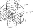
- FIG. 1is a schematic cross-sectional view of an embodiment of a unidirectional valve arranged within a hanger, in accordance with embodiments of the present disclosure
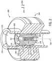
- FIG. 2is an isometric sectional view of an embodiment of a unidirectional valve arranged within a hanger, in accordance with embodiments of the present disclosure
- FIG. 3is a schematic cross-sectional view of an embodiment of a unidirectional valve having body lugs, in accordance with embodiments of the present disclosure
- FIG. 4is a schematic cross-sectional view of an embodiment of a tubing hanger having hanger lugs, in accordance with embodiments of the present disclosure
- FIG. 5is a top plan cross-sectional view of an embodiment of a unidirectional valve having body lugs, in accordance with embodiments of the present disclosure
- FIG. 6is a top plan cross-sectional view of an embodiment of a tubing hanger having hanger lugs, in accordance with embodiments of the present disclosure
- FIG. 7Ais a top plan cross-sectional view of an embodiment of a unidirectional valve arranged within a tubing hanger, in accordance with embodiments of the present disclosure
- FIG. 7Bis a top plan cross-sectional view of an embodiment of a unidirectional vale arranged within a tubing hanger, in accordance with embodiments of the present disclosure.
- FIG. 8is a flow chart of an embodiment of a method for securing a unidirectional valve to a tubing hanger, in accordance with embodiments of the present disclosure.
- Embodiments of the present disclosureare directed toward an axially restricted pressure shuttle, which may include a valve installed in a downhole component, such as a hanger.
- the valveis non-threadingly coupled to the component, for example, utilizing radial lugs that interact with radial lugs of the downhole components to block axial movement of the valve after the valve is positioned in a locked position.
- the valveincludes outwardly extending radial lugs that pass through gaps between inwardly extending radial lugs of the hanger as the valve is moved axially through the hanger. Once past the lugs of the hanger, the valve may be rotated to align the respective lugs with one another. Accordingly, axial movement of the valve is restricted due to the axial alignment of the respective lugs.
- Embodiments of the present disclosuremay be easier or faster to install than threaded methods in that fewer rotations are utilized to align the lugs than to engage mating threads.
- the valvemay be installed using less than a full rotation of the valve due to the removal of the frictional coupling (e.g., threads) in favor of the lug arrangement.
- the valvemay also be easier to remove, and be removable with less force, since threads will not be disengaged.
- systems of the present disclosureare also easier to manufacture because tolerances may not be as close as for threaded components.
- componentsmay be smaller (e.g., shorter) due to the removal of the threads.
- a feedback mechanismmay be provided utilizing embodiments of the present disclosure. For example, if an operator had difficulty rotating or removing the valve, it may be attributed to an upward force on the valve, which would drive the lugs against one another. As such, removal may be delayed until the pressure is contained.
- FIG. 1is a schematic side view of an embodiment of a pressure control system 100 including a unidirectional valve 102 (e.g., back pressure valve (BPV), check valve, one-way valve, etc.) positioned within a bore 104 of a tubing hanger 106 .
- the unidirectional valve 102includes threads 108 to facilitate coupling to the tubing hanger 106 .
- the tubing hanger 106may include corresponding threads for installation of the unidirectional valve 102 .
- the tubing hanger 106may also be a casing hanger and/or a portion of a wellhead.
- the unidirectional valve 102allows flow into a wellbore in a single direction and blocks flow in the opposite direction.
- the illustrated unidirectional valve 102enables flow in a downstream direction 110 and blocks flow in an upstream direction 112 .
- the downstream direction 110is the direction of flow into the wellbore and the upstream direction 112 is the direction of flow out of the wellbore.
- the illustrated unidirectional valve 102has a valve assembly 114 that may include a flange 116 and an elongate member 118 that extends from the flange 116 to or near a bottom end 120 of the unidirectional valve 102 .
- the flange 116may have a seal 122 that blocks fluid from passing between the flange 116 and a shoulder 124 on a body 126 of the unidirectional valve 102 .
- a spring 128surrounds at least a portion of the elongate member 118 to help control the movement of the valve assembly 114 .
- the spring 128In operation, as fluid flows in the downstream direction 110 , the spring 128 is compressed and the flange 116 is driven away from the shoulder 124 to enable fluid flow past the elongate member 118 and through the bore 104 .
- the spring 128is biased so that absent the external force, for example from a fluid flow, the flange 116 is driven against the shoulder 124 .
- the illustrated unidirectional valve 102includes the valve assembly 114
- the unidirectional valve 102may be a ball check valve, a spring check valve, diaphragm check valve, a swing check valve, a stop check valve, a lift check valve, or any other reasonable device that enables flow in a direction and blocks flow in an opposite direction.
- the unidirectional valve 102is threaded into the hanger 106 . Accordingly, engagement between the unidirectional valve 102 and the hanger 106 may be accomplished by aligning the unidirectional valve 102 and the hanger 106 and then rotating the unidirectional valve 102 a certain number of times until a sufficient number of threads are engaged, thereby forming a coupling between the unidirectional valve 102 and the hanger 106 to restrict axial movement (e.g., along a wellbore axis 132 ) of the unidirectional valve 102 . This may be referred to as a friction coupling because friction between mating threads blocks axial movement of the valve relative to the hanger.
- the threads of either the unidirectional valve 102 or the hanger 106may be damaged, for example, due to tripping of components into and out of the well.
- the threads for each of the componentsmay be different sizes (e.g., pitch, units, etc.) and therefore, various components at the well site may not correspond with other another.
- Embodiments of the present disclosuredescribe a unidirectional valve that may be installed without threaded fittings, therefore reducing or eliminating drawbacks found in present technologies. Moreover, in embodiments, the unidirectional valve may be coupled to the hanger utilizing fewer rotations of the unidirectional valve, for example, less than one full rotation, thereby reducing installation time. Furthermore, as will be described, in various embodiments one or more features may be utilized to guide the unidirectional valve into position.
- FIG. 2is an isometric sectional view of an embodiment of a unidirectional valve 200 arranged within a hanger 204 .
- the illustrated unidirectional valve 202includes a body 206 including a valve assembly 208 , similar to the poppet valve 24 illustrated in FIG. 1 .
- the valve assembly 208moves axially along an axis 210 in response to pressure.
- the valve assembly 208may be biased toward a certain position, such as an open position, which would enable flow through a valve bore 212 , and a closed position, which would block flow through the valve bore 214 .
- the positionmay be changed based on pressure exerted by a working fluid.
- the valve assembly 208may be arranged in a closed position until acted upon by a force from an upstream portion of the valve, which would be a fluid flowing into the wellbore in operation.
- the illustrated body 206includes body lugs 214 , which may also be referred to as segmented radial beams, extending radially outward from the axis 210 .
- the body lugs 214are arranged circumferentially about a circumference 218 of the body 206 , with spaces between, as will be described herein.
- the body lugs 216may be utilized to restrict axial movement of the valve 202 .
- the illustrated valve 202further includes a slanted lower edge 218 , which may be utilized to guide the valve 202 into position.
- the slanted lower edge 218may engage one or more features of the hanger 204 to facilitate alignment of the valve 202 with a hanger bore 220 . Because the illustrated valve 202 is not coupled to threads of the hanger 204 , damage to sealing or other engagement surfaces may be reduced.
- the illustrated hangerincludes a shoulder 222 and a hanger lug 224 .
- the shoulder 222may extend circumferentially about a circumference 226 of the hanger bore 220
- the hanger lug 224may correspond to a plurality of hanger lugs 224 arranged circumferentially about the circumference 226 with gaps or spaces 228 between hanger lugs 224 .
- the gaps 228may be larger than or equal to a width of the body lugs 214 , thereby facilitating axial movement of the valve 202 when the body lugs 214 and the gaps 228 are aligned.
- each of the shoulder 222 and the hanger lugs 224extend radially inward toward the axis 210 .
- the shoulder 222 and the hanger lugs 224extend the same distance toward the axis 210 .
- the shoulder 222 or the hanger lugs 224may extend further inward.
- the hanger lugs 224are axially offset from the shoulder 222 by a distance 230 .
- the hanger lugs 224offset from the shoulder 222 by the distance 230 such that, in the embodiment illustrated in FIG. 2 , the hanger lugs 224 are above or closer to a top of the hanger 204 than the shoulder 222 .
- An opening 232spans the distance 230 to receive the body lugs 214 .
- the hanger lugs 224include an angled surface 238 at an upper end of the hanger lugs 224 .
- the slanted lower edge 218may contact the angled surface 230 to facilitate alignment of the valve 202 with the hanger bore 220 .
- the body lugs 214may be aligned with the gaps 228 to facilitate coupling the valve 202 to the body 204 .
- FIG. 3is a cross-sectional view of an embodiment of a unidirectional valve 300 that includes a bore 302 extending along a length 304 of the valve 300 .
- the valve 300is formed by a body 306 , which may be a metallic material, and is illustrated as a continuous, integral piece in the illustrated embodiment.
- the body 306may be formed from multiple different components that are coupled together, and in various embodiments, the components may be formed by different materials.
- a lower end 308may be formed from a material that is suitable for sour or corrosive service while an upper end 310 may be formed from a different material, which may reduce costs associated with the valve 300 .
- the valve 300may include coatings, liners, and the like.
- the bore 302includes a reduced diameter portion 312 through which a valve assembly 314 extends. It should be appreciated that certain features, such as a resilient or biasing member associated with the valve assembly 314 , are removed for clarity.
- the illustrated body 306includes body lugs 316 extending radially outward from an axis 318 of the valve 300 . That is, the body lugs 316 extend away from the body 306 with respect to the axis 318 .
- the body lugs 316include a length 320 and a height 322 .
- the length 320refers to the radial extent of the body lugs 316 , for example beyond a circumference 324 of the body 306 .
- the height 322refers to an axial extent of the body lugs 316 .
- the lugs 316may not be formed from a continuous, extending piece about the circumference 324 , and rather, are discrete sections having a width and spaces between the body lugs 316 . It should be appreciated that any number of body lugs 316 may be included and that the number of body lugs 316 included may vary based on expected wellbore conditions.
- the illustrated valve 300further includes a circumferential groove 326 that receives a seal 328 .
- the seal 328may be compressed via engagement with the wellhead and/or hanger, thereby providing at least one fluid barrier. While the illustrated embodiment includes a single seal 328 , it should be appreciated that multiple grooves 326 and seals 328 may be included. As shown, the groove 326 and seal 328 are arranged axially lower or downstream (e.g., relative to a direction of fluid flowing into the wellbore) of the body lugs 316 . Accordingly, during installation, the seal 328 may be set when the value 300 is put into position, for example, when the body lugs 316 are arranged within an opening of the hanger, as described above.
- FIG. 4is a cross-sectional view of an embodiment of a tubing hanger 400 .
- the illustrated tubing hanger 400includes a bore 402 extending along a length 404 of the tubing hanger 400 .
- the tubing hanger 400further includes a body 406 , which may be metallic.
- the tubing hanger 400includes an axial restraint system 408 , which includes a hanger lug 410 and a shoulder 412 .
- the hanger lug 410may not extend circumferentially about a circumference 414 of the bore 402 , but rather, may be formed by a plurality of hanger lugs 410 extending a certain circumferential distance about the bore 402 .
- hanger lugs 410there may be a series of hanger lugs 410 that are separated by gaps to facilitate axial passage of the body lugs 316 ( FIG. 3 ). As will be described, axial passage of the body lugs 316 positions the body lugs 316 into an opening in the hanger.
- the illustrated hanger lugs 410extend a length 416 radially inward toward an axis 418 and further include a height 420 .
- the hanger lugs 410are axially separated from the shoulder 412 by a distance 422 that forms an opening 424 between the hanger lugs 410 and the shoulder 412 .
- the distance 422may be substantially equal to or larger than the height 322 of the body lugs 316 , thereby facilitating arrangement of the body lugs 316 within the opening 424 .
- the opening 424includes a length 426 that extends radially outward from the axis 418 , with respect to the hanger lugs 410 .
- a diameter 428 of the opening 424may be substantially equal to a diameter 430 of the bore 402 .
- the shoulder 412includes a length 432 that extends radially inward toward the axis 418 .
- the length 432is substantially equal to the length 416 .
- the shoulder 412extends continuously about the circumference 414 , and as a result, may support the body lugs 316 regardless of their position within the opening 424 . That is, the shoulder 412 may support the body lugs 316 as they are rotated about the axis 418 to align with the hanger lugs 410 and block axial movement of the valve 300 .
- the shoulder 412may block additional downward movement of the valve 300 .
- the shoulder 412may be arranged at a predetermined position to align the seal 328 with a sealing surface of the tubing hanger 400 .
- FIG. 5is a cross-sectional top plan view of an embodiment of the valve 300 .
- the body lugs 316are illustrated extending radially outward from the axis 318 , for example by the length 320 .
- spaces 500are arranged between the plurality of body lugs 316 .
- the spaceshave a width 502 , which may correspond to a width between the hanger lugs 410 , as will be described below, to enable the body lugs 316 to pass axially through the spaces between the hanger lugs 410 .
- the body lugs 316have a width 504 .
- the width 504may be substantially equal to the width 502 .
- the width 504may be larger than or smaller than the width 502 .
- the respective widths 504 of the body lugs 316may not be equal, with certain lugs being larger than other lugs.
- the width 502 of the spaces 500may not be equal. In this manner, certain engagement positions may be predetermined.
- the body lugs 316are arranged equally about the circumference 324 . However, it should be appreciated that the body lugs 316 may not be equally arranged about the circumference 324 , with more or fewer body lugs 316 being arranged at various locations. Furthermore, while the illustrated valve 300 includes nine body lugs 316 , any number of body lugs may be included as particularly selected for wellbore operations. For example, there may be 1, 2, 3, 4, 5, 6, 7, 8, 9, 10, or any other number of body lugs.
- FIG. 6is a cross-sectional top plan view of an embodiment of the tubing hanger 400 .
- the hanger lugs 410are illustrated extending radially inward toward the axis 418 , for example by the length 416 .
- gaps 600are arranged between the plurality of hanger lugs 410 .
- the gaps 600have a width 602 , which may correspond to the width 504 of the body lugs 316 , thereby enabling axial passage through the gaps 600 .
- the hanger lugs 410have a width 604 . It should be appreciated that, in various embodiments, the width 604 may be substantially equal to the width 602 .
- the width 604may be larger than or smaller than the width 602 .
- the respective widths 604 of the hanger lugsmay not be equal, with certain lugs being larger than other lugs.
- the width 602 of the gaps 600may not be equal. In this manner, certain engagement positions may be predetermined, as noted with respect to the spaces 500 .
- the hanger lugs 410are arranged equally about the circumference 414 . However, it should be appreciated that the hanger lugs 410 may not be equally arranged about the circumference 414 , with more or fewer hanger lugs 410 being arranged at various locations. Furthermore, while the illustrated tubing hanger 400 includes six hanger lugs 410 , any number of hanger lugs may be included as particularly selected for wellbore operations. For example, there may be 1, 2, 3, 4, 5, 6, 7, 8, 9, 10, or any other number of body lugs. As illustrated, the shoulder 412 is visible through the gaps 600 .
- the shoulder 412extends continuously about the circumference 414 and extends the length 432 , which is substantially equal to the length 416 in the illustrated embodiment.
- the body lugs 316will pass through the gaps 600 and will rest on the shoulder 412 . Thereafter, the valve 300 may be rotated such that the body lugs 316 align with the hanger lugs 410 , thereby blocking axial movement of the valve 300 .
- FIG. 7Ais a cross-sectional plan view of an embodiment of the valve 300 arranged within the bore 402 of the tubing hanger 400 .
- the shoulder 412has been removed to illustrate the position of the body lugs 316 with respect to the hanger lugs 410 .
- the body lugs 316are axially aligned with the gaps 600 and the hanger lugs 310 are axially aligned with the spaces 500 .
- axial movement of the valve 300 relative to the tubing hanger 400is enabled, which provides a path for movement of the body lugs 316 into the opening 232 ( FIG. 2 ), 424 ( FIG. 4 ).
- FIG. 7Bis a cross-sectional plan view of an embodiment of the valve 300 axially restricted by the tubing hanger 400 .
- the valve 300has been rotated such that the body lugs 316 are aligned with the hanger lugs 410 .
- the rotationis less than one full rotation of the valve 300 .
- the rotationcan be approximately 10 degrees, approximately 20 degrees, approximately 30 degrees, approximately 40 degrees, approximately 50 degrees, approximately 60 degrees, approximately 70 degrees, approximately 80 degrees, approximately 90 degrees, approximately 100 degrees, approximately 110 degrees, approximately 120 degrees, approximately 130 degrees, approximately 140 degrees, approximately 150 degrees, approximately 160 degrees, approximately 170 degrees, approximately 180 degrees, approximately 190 degrees, approximately 200 degrees, approximately 210 degrees, approximately 220 degrees, approximately 230 degrees, approximately 240 degrees, approximately 250 degrees, approximately 260 degrees, approximately 270 degrees, approximately 280 degrees, approximately 290 degrees, approximately 300 degrees, approximately 310 degrees, approximately 320 degrees, approximately 330 degrees, approximately 340 degrees, approximately 350 degrees, or any other reasonable rotational amount.
- the gaps 600 and spaces 500are aligned. As a result, axial movement of the valve 300 is blocked via contact between the body lugs 316 and the hanger lugs 410 .
- FIGS. 7A and 7Binclude an equal number of body lugs 316 and hanger lugs 410 , that in other embodiments that may not be an equal number. For example, there may be more hanger lugs 410 than body lugs 316 . Furthermore, while the illustrated embodiment includes eight body lugs 316 and eight hanger lugs 410 , any other reasonable number of lugs 316 , 410 may be included.
- FIG. 8is a flow chart of an embodiment of a method 800 for installing a unidirectional valve, such as the unidirectional valve 300 , into a hanger, such as the tubing hanger 400 .
- a unidirectional valvesuch as the unidirectional valve 300
- the hangermay be replaced with a wellhead or any other wellbore component.
- the unidirectional valveis aligned with a bore, such as a bore of a tubing hanger (block 802 ).
- the valve 300may be aligned with the bore 402 .
- alignmentalso includes aligning the body lugs 316 of the valve 300 with the gaps 600 of the tubing hanger.
- the valveis moved axially with respect to the hanger (block 804 ).
- the valve 300may be moved along the axis 318 such that the body lugs 316 move past the hanger lugs 410 , through the gaps 600 , and into the opening 424 . Movement of the valve may enable landing the valve onto a shoulder of the hanger (block 806 ).
- the axial movement of the valve 300may cause the body lugs 316 to engage the shoulder 412 , thereby blocking further axial movement of the valve 300 .
- the valvemay then be rotated relative to the hanger (block 808 ).
- Rotation of the valve 300may be sufficient to align the body lugs 316 and the hanger lugs 410 such that axial movement of the valve 300 is blocked. For example, an upward force on the valve 300 would drive the body lugs 316 into the hanger lugs 410 , thereby blocking movement. In this manner, the valve 300 may be secured to the hanger 400 without threading the valve 300 to the hanger 400 . In other words, the valve 300 may be secured to the hanger 400 with less than a full rotation of the valve 300 .
Landscapes
- Engineering & Computer Science (AREA)
- General Engineering & Computer Science (AREA)
- Mechanical Engineering (AREA)
- Life Sciences & Earth Sciences (AREA)
- Geology (AREA)
- Mining & Mineral Resources (AREA)
- Physics & Mathematics (AREA)
- Environmental & Geological Engineering (AREA)
- Fluid Mechanics (AREA)
- General Life Sciences & Earth Sciences (AREA)
- Geochemistry & Mineralogy (AREA)
- Valve Housings (AREA)
Abstract
Description
Claims (19)
Priority Applications (1)
| Application Number | Priority Date | Filing Date | Title |
|---|---|---|---|
| US16/280,203US11015732B2 (en) | 2012-12-31 | 2019-02-20 | Axially restricted pressure shuttle |
Applications Claiming Priority (7)
| Application Number | Priority Date | Filing Date | Title |
|---|---|---|---|
| US201261747479P | 2012-12-31 | 2012-12-31 | |
| US13/832,884US9212758B2 (en) | 2012-12-31 | 2013-03-15 | Quick connect valve actuator |
| US201562172544P | 2015-06-08 | 2015-06-08 | |
| US14/949,324US9759240B2 (en) | 2012-12-31 | 2015-11-23 | No-bolt security latching system |
| US15/175,122US10132422B2 (en) | 2012-12-31 | 2016-06-07 | Compound express actuator connection |
| US16/158,490US10774945B2 (en) | 2012-12-31 | 2018-10-12 | Compound express actuator connection |
| US16/280,203US11015732B2 (en) | 2012-12-31 | 2019-02-20 | Axially restricted pressure shuttle |
Related Parent Applications (1)
| Application Number | Title | Priority Date | Filing Date |
|---|---|---|---|
| US16/158,490Continuation-In-PartUS10774945B2 (en) | 2012-12-31 | 2018-10-12 | Compound express actuator connection |
Publications (2)
| Publication Number | Publication Date |
|---|---|
| US20190178412A1 US20190178412A1 (en) | 2019-06-13 |
| US11015732B2true US11015732B2 (en) | 2021-05-25 |
Family
ID=66735302
Family Applications (1)
| Application Number | Title | Priority Date | Filing Date |
|---|---|---|---|
| US16/280,203Expired - Fee RelatedUS11015732B2 (en) | 2012-12-31 | 2019-02-20 | Axially restricted pressure shuttle |
Country Status (1)
| Country | Link |
|---|---|
| US (1) | US11015732B2 (en) |
Families Citing this family (3)
| Publication number | Priority date | Publication date | Assignee | Title |
|---|---|---|---|---|
| US20230228167A1 (en)* | 2020-05-04 | 2023-07-20 | SPM Oil & Gas PC LLC | Back pressure valve with latching engagement system and method |
| US12435598B2 (en)* | 2023-08-28 | 2025-10-07 | Texas Highland Holdings Llc | Valves for well systems and methods of operating same |
| US20250075590A1 (en)* | 2023-08-28 | 2025-03-06 | Heshka Oil | Valves for well systems and methods of operating same |
Citations (98)
| Publication number | Priority date | Publication date | Assignee | Title |
|---|---|---|---|---|
| US2610820A (en) | 1946-11-15 | 1952-09-16 | Edward Valves Inc | Valve bonnet structure |
| FR1195213A (en) | 1957-03-25 | 1959-11-16 | Int Basic Economy Corp | Slide valve |
| US2935166A (en) | 1957-08-14 | 1960-05-03 | Monroe Calculating Machine | Motor reversing means for calculating machines |
| US3082792A (en) | 1961-03-01 | 1963-03-26 | Honeywell Regulator Co | Pneumatic actuator |
| US3115068A (en) | 1962-09-11 | 1963-12-24 | Rockwell Mfg Co | Valve operating mechanism |
| US3139898A (en) | 1961-05-12 | 1964-07-07 | Milesmaster Inc Of America | Plastic pressure regulator |
| US3146682A (en) | 1962-04-20 | 1964-09-01 | Bendix Corp | Fluid pressure motor construction |
| US3175473A (en) | 1962-05-01 | 1965-03-30 | Grinnell Corp | Spring and fluid pressure actuator |
| US3293992A (en) | 1964-08-25 | 1966-12-27 | Cash A W Co | Fluid actuator |
| US3380470A (en) | 1965-11-30 | 1968-04-30 | Texsteam Corp | Flow regulator with radially expanding elastomeric block |
| GB1148817A (en) | 1967-10-25 | 1969-04-16 | Kerotest Mfg Corp | Valve locks |
| US3593959A (en) | 1969-07-23 | 1971-07-20 | Bobby Howard Greene | Pocket unloader valve operator |
| US3792717A (en) | 1972-06-15 | 1974-02-19 | E Tibbals | Pressure regulator |
| US3811457A (en) | 1971-09-30 | 1974-05-21 | Goodyear Tire & Rubber | Over pressurization release device and valve |
| US3882400A (en) | 1972-11-27 | 1975-05-06 | Sony Corp | Broadcast receiver |
| US3955793A (en) | 1974-06-21 | 1976-05-11 | Exxon Production Research Company | Valve stem static seal system |
| US3958592A (en) | 1974-02-06 | 1976-05-25 | Willis Oil Tool Co. | Safety shut-off valve |
| US3993284A (en) | 1975-06-26 | 1976-11-23 | Acf Industries, Incorporated | Connection of actuator cylinder housing to valve bonnet |
| US4135547A (en) | 1977-03-14 | 1979-01-23 | Baker International Corporation | Quick disengaging valve actuator |
| US4135546A (en) | 1977-04-20 | 1979-01-23 | Acf Industries, Incorporated | Stem packing assembly for gate valves and means for removal |
| GB2022704A (en) | 1978-06-12 | 1979-12-19 | Midland Ross Corp | Cylinder and piston assembly with piston over-tavel indicator |
| US4187764A (en) | 1972-07-12 | 1980-02-12 | The United States Of America As Represented By The United States Department Of Energy | Fast-acting valve actuator |
| US4274432A (en) | 1980-01-21 | 1981-06-23 | Otis Engineering Corporation | Valve |
| US4309022A (en) | 1980-04-14 | 1982-01-05 | Consolidated Controls Corporation | Poppet valve actuator apparatus |
| US4354425A (en) | 1980-05-09 | 1982-10-19 | U.S. Industries, Inc. | Fire-safe valve actuator |
| US4424738A (en) | 1981-11-06 | 1984-01-10 | Air-Dry Corporation | Fluid controller with diaphragm and piston |
| US4480811A (en) | 1981-07-07 | 1984-11-06 | Vsi Corporation | Fail-safe actuator device |
| US4489756A (en) | 1980-07-26 | 1984-12-25 | Schubert & Salzer | Sliding gate fluid control valve |
| US4491060A (en) | 1983-06-30 | 1985-01-01 | Otis Engineering Corporation | Cylinder connection |
| US4527769A (en) | 1983-10-03 | 1985-07-09 | Xomox Corporation | Apparatus for moving a controlled member to a predetermined position |
| US4529330A (en) | 1983-06-30 | 1985-07-16 | Otis Engineering Corporation | Cylinder connection |
| US4585207A (en) | 1985-09-03 | 1986-04-29 | Joy Manufacturing Company | Expanding gate valve with pneumatic actuator |
| GB2168787A (en) | 1984-12-21 | 1986-06-25 | British Nuclear Fuels Plc | Improvements in or relating to valve actuators |
| US4620562A (en) | 1982-09-28 | 1986-11-04 | Butterworth, Inc. | High pressure regulator valve |
| US4624442A (en) | 1985-01-23 | 1986-11-25 | Duffy John W | Control regulator having a rolling diaphragm |
| US4633898A (en) | 1984-10-11 | 1987-01-06 | Sueddeutsche Kuehlerfabrik Julius Fr. Behr Gmbh & Co. Kg | Slide valve with partial-vacuum actuator |
| US4650151A (en) | 1983-01-10 | 1987-03-17 | Fmc Corporation | Subsea gate valve actuator with external manual override and drift adjustment |
| US4721284A (en) | 1986-11-06 | 1988-01-26 | Norriseal Controls | Valve plug design |
| US4768545A (en) | 1987-02-09 | 1988-09-06 | General Motors Corporation | Actuator for air conditioning system |
| US4871143A (en) | 1989-02-15 | 1989-10-03 | Cameron Iron Works Usa, Inc. | Gate valve with supplemental actuator |
| US4934403A (en) | 1989-04-10 | 1990-06-19 | Betts Industries, Inc. | Readily inspectable and cleanable emergency valve for storage tank |
| US4967785A (en) | 1990-04-27 | 1990-11-06 | Baker Hughes Incorporated | Valve actuator |
| EP0416966A2 (en) | 1989-09-05 | 1991-03-13 | Alliedsignal Europe Services Techniques | Pneumatic servomotor |
| EP0486824A1 (en) | 1990-11-20 | 1992-05-27 | Knorr-Bremse Ag | Combined service brake and spring-loaded brake actuator for vehicles |
| CN2121592U (en) | 1992-01-09 | 1992-11-11 | 宗良 | Cylinder valve open/close device |
| US5294090A (en) | 1992-11-25 | 1994-03-15 | Orbit Valve Company | Valve snubber |
| US5464040A (en) | 1987-04-28 | 1995-11-07 | Barber Industries Ltd. | Safety valve actuator |
| US5499648A (en) | 1994-08-30 | 1996-03-19 | Groth Corporation | Sealing means for pressure relief valves and methods of assembly |
| GB2303199A (en) | 1995-07-12 | 1997-02-12 | L B Bentley Limited | Valve assemblies |
| US5964446A (en) | 1996-08-21 | 1999-10-12 | Fisher Controls International, Inc. | Elastomeric element valve |
| US6015134A (en) | 1993-06-28 | 2000-01-18 | Barber Industries Inc. | Pneumatic actuator assembly |
| US6041804A (en) | 1998-02-23 | 2000-03-28 | Chatufale; Vijay R. | Subsea valve actuator and method |
| US6050541A (en) | 1998-06-15 | 2000-04-18 | Chatufale; Vijay R. | Pneumatic valve actuator assembly |
| US6086039A (en) | 1999-04-07 | 2000-07-11 | Saint-Gobain Performance Plastics Corporation | High-efficiency poppet and seat assembly |
| US6089531A (en) | 1994-03-04 | 2000-07-18 | Safoco, Inc. | Valve actuator apparatus |
| US6397892B1 (en) | 2000-08-29 | 2002-06-04 | Enron Machine & Mechnical Services, Inc. | Multi-stage unloader |
| US20020175303A1 (en) | 2002-02-14 | 2002-11-28 | Vijay Chatufale | Hydraulic actuator with built-in pressure compensator |
| US6487960B1 (en) | 2001-08-09 | 2002-12-03 | Hp&T Products, Inc. | Hydraulic failsafe valve actuator |
| US20030034465A1 (en) | 2001-08-15 | 2003-02-20 | Cooper Cameron Corporation | Gate valve actuator with universal mounting arrangement |
| US6659419B2 (en) | 2001-12-26 | 2003-12-09 | Hp&T Products, Inc. | Hydraulic double acting valve actuator |
| US6672331B2 (en) | 2000-07-31 | 2004-01-06 | S. H. Leggitt Company | Bonnet securement for gas pressure regulators |
| US20040007682A1 (en) | 2002-07-12 | 2004-01-15 | Smc Corporation | Two-port vacuum valve capable of adjusting valve-opening |
| US6684897B2 (en) | 2001-03-08 | 2004-02-03 | Worldwide Oilfield Machine, Inc. | Valve actuator and method |
| US6695049B2 (en)* | 2000-07-11 | 2004-02-24 | Fmc Technologies, Inc. | Valve assembly for hydrocarbon wells |
| US20050087712A1 (en) | 2003-10-27 | 2005-04-28 | David Lymberopoulos | Mechanical override for a valve actuator |
| US7124774B2 (en) | 2001-06-06 | 2006-10-24 | Bermad Limited Partnership | Control valve |
| US7159839B2 (en) | 2002-09-02 | 2007-01-09 | Fujikin Incorporated | Control device |
| US20070290154A1 (en) | 2006-06-20 | 2007-12-20 | Ckd Corporation | Air-operated valve |
| CN101093034A (en) | 2006-06-20 | 2007-12-26 | 喜开理株式会社 | Air-operated valve |
| JP2008069795A (en) | 2006-09-12 | 2008-03-27 | Tgk Co Ltd | Atmosphere relief-valve |
| US7647861B2 (en) | 2006-12-22 | 2010-01-19 | Fisher Controls International Llc | Apparatus to seal a shaft to a diaphragm for use in diaphragm actuators |
| JP2010048271A (en) | 2008-08-19 | 2010-03-04 | Hirotek Kk | Piston valve |
| US7708089B2 (en)* | 2008-02-07 | 2010-05-04 | Theresa J. Williams, legal representative | Breech lock stripper rubber pot mounting structure and well drilling equipment comprising same |
| US20110240126A1 (en) | 2010-03-31 | 2011-10-06 | David Lymberopoulos | Safety valve and method of use |
| US8141642B2 (en)* | 2008-05-02 | 2012-03-27 | Weatherford/Lamb, Inc. | Fill up and circulation tool and mudsaver valve |
| CN202302237U (en) | 2011-09-28 | 2012-07-04 | 芜湖市安芜汽车制动元件有限公司 | Pneumatically-controlled stop valve |
| CN202432085U (en) | 2011-12-16 | 2012-09-12 | 四川天工阀门有限公司 | Actuator for safety valve of pneumatic diaphragm |
| US20120227983A1 (en) | 2010-08-04 | 2012-09-13 | David Lymberopoulos | Safety valve control system and method of use |
| DE102011015646A1 (en) | 2011-03-31 | 2012-10-04 | Festo Ag & Co. Kg | Fluid operated diaphragm drive |
| US8282070B2 (en) | 2007-09-21 | 2012-10-09 | Fisher Controls International Llc | Apparatus and methods for manual override operation of a linear actuator |
| US8322359B2 (en) | 2005-03-25 | 2012-12-04 | O.M.T. Officina Meccanica Tartarini S.r.I. | Gas pressure regulator and method for assembling and disassembling the regulator |
| US20120318388A1 (en) | 2011-06-17 | 2012-12-20 | NEUMO Armaturenfabrik Apparatebau-Metallgiesserei GmbH + Co. KG | Double-Seat Valve Device |
| US8522877B2 (en) | 2009-08-21 | 2013-09-03 | Baker Hughes Incorporated | Sliding sleeve locking mechanisms |
| US8636058B2 (en)* | 2008-04-09 | 2014-01-28 | Cameron International Corporation | Straight-bore back pressure valve |
| US20140034392A1 (en)* | 2010-05-04 | 2014-02-06 | Cameron West Coast Inc. | Hydrocarbon Well Completion System and Method of Completing a Hydrocarbon Well |
| US8708309B2 (en) | 2009-04-27 | 2014-04-29 | Emerson Process Management Regulator Technologies, Inc. | Self-aligning spring seat for fluid regulator and fluid regulator comprising self-aligning spring seat |
| US20140138564A1 (en) | 2012-11-16 | 2014-05-22 | Vetco Gray Inc | Combination diaphragm piston actuator |
| WO2014099505A1 (en) | 2012-12-17 | 2014-06-26 | Vetco Gray Inc. | Swivel top shaft valve actuator |
| US20140174554A1 (en) | 2012-12-20 | 2014-06-26 | Vetco Gray Inc. | Robust Quick-Connection Mechanism For Use With Valve Actuator Assemblies and Linearly Actuated Valves and Related Methods |
| US8864102B2 (en) | 2011-07-15 | 2014-10-21 | Mecanique Analytique Inc. | Actuator |
| US8991420B2 (en) | 2012-11-16 | 2015-03-31 | Ge Oil & Gas Pressure Control Lp | Non-rising stem actuator |
| US9033308B2 (en) | 2010-06-30 | 2015-05-19 | Samson Aktiengesellschaft | Control device with improved stem connector and display |
| US20150204456A1 (en) | 2012-11-16 | 2015-07-23 | Ge Oil & Gas Pressure Control Lp | Combination Diaphragm Piston Actuator |
| US9212758B2 (en) | 2012-12-31 | 2015-12-15 | Ge Oil & Gas Pressure Control Lp | Quick connect valve actuator |
| US20160186527A1 (en) | 2014-12-30 | 2016-06-30 | Cameron International Corporation | Back pressure valve |
| US20160327179A1 (en) | 2015-05-06 | 2016-11-10 | F.l.P. Formatura lniezione Polimeri S.p.A. | Valve |
| CN205806614U (en) | 2016-07-14 | 2016-12-14 | 江苏金石机械集团有限公司 | Inserted back pressure valve |
| US9759240B2 (en) | 2012-12-31 | 2017-09-12 | Ge Oil & Gas Pressure Control Lp | No-bolt security latching system |
- 2019
- 2019-02-20USUS16/280,203patent/US11015732B2/ennot_activeExpired - Fee Related
Patent Citations (104)
| Publication number | Priority date | Publication date | Assignee | Title |
|---|---|---|---|---|
| US2610820A (en) | 1946-11-15 | 1952-09-16 | Edward Valves Inc | Valve bonnet structure |
| FR1195213A (en) | 1957-03-25 | 1959-11-16 | Int Basic Economy Corp | Slide valve |
| US2935166A (en) | 1957-08-14 | 1960-05-03 | Monroe Calculating Machine | Motor reversing means for calculating machines |
| US3082792A (en) | 1961-03-01 | 1963-03-26 | Honeywell Regulator Co | Pneumatic actuator |
| US3139898A (en) | 1961-05-12 | 1964-07-07 | Milesmaster Inc Of America | Plastic pressure regulator |
| US3146682A (en) | 1962-04-20 | 1964-09-01 | Bendix Corp | Fluid pressure motor construction |
| US3175473A (en) | 1962-05-01 | 1965-03-30 | Grinnell Corp | Spring and fluid pressure actuator |
| US3115068A (en) | 1962-09-11 | 1963-12-24 | Rockwell Mfg Co | Valve operating mechanism |
| US3293992A (en) | 1964-08-25 | 1966-12-27 | Cash A W Co | Fluid actuator |
| US3380470A (en) | 1965-11-30 | 1968-04-30 | Texsteam Corp | Flow regulator with radially expanding elastomeric block |
| GB1148817A (en) | 1967-10-25 | 1969-04-16 | Kerotest Mfg Corp | Valve locks |
| US3593959A (en) | 1969-07-23 | 1971-07-20 | Bobby Howard Greene | Pocket unloader valve operator |
| US3811457A (en) | 1971-09-30 | 1974-05-21 | Goodyear Tire & Rubber | Over pressurization release device and valve |
| US3792717A (en) | 1972-06-15 | 1974-02-19 | E Tibbals | Pressure regulator |
| US4187764A (en) | 1972-07-12 | 1980-02-12 | The United States Of America As Represented By The United States Department Of Energy | Fast-acting valve actuator |
| US3882400A (en) | 1972-11-27 | 1975-05-06 | Sony Corp | Broadcast receiver |
| US3958592A (en) | 1974-02-06 | 1976-05-25 | Willis Oil Tool Co. | Safety shut-off valve |
| US3955793A (en) | 1974-06-21 | 1976-05-11 | Exxon Production Research Company | Valve stem static seal system |
| US3993284A (en) | 1975-06-26 | 1976-11-23 | Acf Industries, Incorporated | Connection of actuator cylinder housing to valve bonnet |
| US4135547A (en) | 1977-03-14 | 1979-01-23 | Baker International Corporation | Quick disengaging valve actuator |
| US4135546A (en) | 1977-04-20 | 1979-01-23 | Acf Industries, Incorporated | Stem packing assembly for gate valves and means for removal |
| GB2022704A (en) | 1978-06-12 | 1979-12-19 | Midland Ross Corp | Cylinder and piston assembly with piston over-tavel indicator |
| US4274432A (en) | 1980-01-21 | 1981-06-23 | Otis Engineering Corporation | Valve |
| US4309022A (en) | 1980-04-14 | 1982-01-05 | Consolidated Controls Corporation | Poppet valve actuator apparatus |
| US4354425A (en) | 1980-05-09 | 1982-10-19 | U.S. Industries, Inc. | Fire-safe valve actuator |
| US4489756A (en) | 1980-07-26 | 1984-12-25 | Schubert & Salzer | Sliding gate fluid control valve |
| US4480811A (en) | 1981-07-07 | 1984-11-06 | Vsi Corporation | Fail-safe actuator device |
| US4424738A (en) | 1981-11-06 | 1984-01-10 | Air-Dry Corporation | Fluid controller with diaphragm and piston |
| US4620562A (en) | 1982-09-28 | 1986-11-04 | Butterworth, Inc. | High pressure regulator valve |
| US4650151A (en) | 1983-01-10 | 1987-03-17 | Fmc Corporation | Subsea gate valve actuator with external manual override and drift adjustment |
| US4529330A (en) | 1983-06-30 | 1985-07-16 | Otis Engineering Corporation | Cylinder connection |
| US4491060A (en) | 1983-06-30 | 1985-01-01 | Otis Engineering Corporation | Cylinder connection |
| US4527769A (en) | 1983-10-03 | 1985-07-09 | Xomox Corporation | Apparatus for moving a controlled member to a predetermined position |
| US4633898A (en) | 1984-10-11 | 1987-01-06 | Sueddeutsche Kuehlerfabrik Julius Fr. Behr Gmbh & Co. Kg | Slide valve with partial-vacuum actuator |
| GB2168787A (en) | 1984-12-21 | 1986-06-25 | British Nuclear Fuels Plc | Improvements in or relating to valve actuators |
| US4624442A (en) | 1985-01-23 | 1986-11-25 | Duffy John W | Control regulator having a rolling diaphragm |
| US4585207A (en) | 1985-09-03 | 1986-04-29 | Joy Manufacturing Company | Expanding gate valve with pneumatic actuator |
| US4721284A (en) | 1986-11-06 | 1988-01-26 | Norriseal Controls | Valve plug design |
| US4768545A (en) | 1987-02-09 | 1988-09-06 | General Motors Corporation | Actuator for air conditioning system |
| US5464040A (en) | 1987-04-28 | 1995-11-07 | Barber Industries Ltd. | Safety valve actuator |
| US4871143A (en) | 1989-02-15 | 1989-10-03 | Cameron Iron Works Usa, Inc. | Gate valve with supplemental actuator |
| US4934403A (en) | 1989-04-10 | 1990-06-19 | Betts Industries, Inc. | Readily inspectable and cleanable emergency valve for storage tank |
| EP0416966A2 (en) | 1989-09-05 | 1991-03-13 | Alliedsignal Europe Services Techniques | Pneumatic servomotor |
| US5067392A (en) | 1989-09-05 | 1991-11-26 | Bendix Europe Services Techniques | Pneumatic booster |
| US4967785A (en) | 1990-04-27 | 1990-11-06 | Baker Hughes Incorporated | Valve actuator |
| EP0486824A1 (en) | 1990-11-20 | 1992-05-27 | Knorr-Bremse Ag | Combined service brake and spring-loaded brake actuator for vehicles |
| CN2121592U (en) | 1992-01-09 | 1992-11-11 | 宗良 | Cylinder valve open/close device |
| US5294090A (en) | 1992-11-25 | 1994-03-15 | Orbit Valve Company | Valve snubber |
| US6015134A (en) | 1993-06-28 | 2000-01-18 | Barber Industries Inc. | Pneumatic actuator assembly |
| US6089531A (en) | 1994-03-04 | 2000-07-18 | Safoco, Inc. | Valve actuator apparatus |
| US6854704B1 (en) | 1994-03-04 | 2005-02-15 | Safoco, Inc. | Valve actuator apparatus |
| US5499648A (en) | 1994-08-30 | 1996-03-19 | Groth Corporation | Sealing means for pressure relief valves and methods of assembly |
| GB2303199A (en) | 1995-07-12 | 1997-02-12 | L B Bentley Limited | Valve assemblies |
| US5964446A (en) | 1996-08-21 | 1999-10-12 | Fisher Controls International, Inc. | Elastomeric element valve |
| US6041804A (en) | 1998-02-23 | 2000-03-28 | Chatufale; Vijay R. | Subsea valve actuator and method |
| US6050541A (en) | 1998-06-15 | 2000-04-18 | Chatufale; Vijay R. | Pneumatic valve actuator assembly |
| US6086039A (en) | 1999-04-07 | 2000-07-11 | Saint-Gobain Performance Plastics Corporation | High-efficiency poppet and seat assembly |
| US6695049B2 (en)* | 2000-07-11 | 2004-02-24 | Fmc Technologies, Inc. | Valve assembly for hydrocarbon wells |
| US6672331B2 (en) | 2000-07-31 | 2004-01-06 | S. H. Leggitt Company | Bonnet securement for gas pressure regulators |
| US6397892B1 (en) | 2000-08-29 | 2002-06-04 | Enron Machine & Mechnical Services, Inc. | Multi-stage unloader |
| US6684897B2 (en) | 2001-03-08 | 2004-02-03 | Worldwide Oilfield Machine, Inc. | Valve actuator and method |
| US7124774B2 (en) | 2001-06-06 | 2006-10-24 | Bermad Limited Partnership | Control valve |
| US6487960B1 (en) | 2001-08-09 | 2002-12-03 | Hp&T Products, Inc. | Hydraulic failsafe valve actuator |
| US20030034465A1 (en) | 2001-08-15 | 2003-02-20 | Cooper Cameron Corporation | Gate valve actuator with universal mounting arrangement |
| US6659419B2 (en) | 2001-12-26 | 2003-12-09 | Hp&T Products, Inc. | Hydraulic double acting valve actuator |
| US20020175303A1 (en) | 2002-02-14 | 2002-11-28 | Vijay Chatufale | Hydraulic actuator with built-in pressure compensator |
| US20040007682A1 (en) | 2002-07-12 | 2004-01-15 | Smc Corporation | Two-port vacuum valve capable of adjusting valve-opening |
| US7159839B2 (en) | 2002-09-02 | 2007-01-09 | Fujikin Incorporated | Control device |
| US20050087712A1 (en) | 2003-10-27 | 2005-04-28 | David Lymberopoulos | Mechanical override for a valve actuator |
| US8322359B2 (en) | 2005-03-25 | 2012-12-04 | O.M.T. Officina Meccanica Tartarini S.r.I. | Gas pressure regulator and method for assembling and disassembling the regulator |
| US20070290154A1 (en) | 2006-06-20 | 2007-12-20 | Ckd Corporation | Air-operated valve |
| CN101093034A (en) | 2006-06-20 | 2007-12-26 | 喜开理株式会社 | Air-operated valve |
| JP2008069795A (en) | 2006-09-12 | 2008-03-27 | Tgk Co Ltd | Atmosphere relief-valve |
| US7647861B2 (en) | 2006-12-22 | 2010-01-19 | Fisher Controls International Llc | Apparatus to seal a shaft to a diaphragm for use in diaphragm actuators |
| US8282070B2 (en) | 2007-09-21 | 2012-10-09 | Fisher Controls International Llc | Apparatus and methods for manual override operation of a linear actuator |
| US7708089B2 (en)* | 2008-02-07 | 2010-05-04 | Theresa J. Williams, legal representative | Breech lock stripper rubber pot mounting structure and well drilling equipment comprising same |
| US9422788B2 (en) | 2008-04-09 | 2016-08-23 | Cameron International Corporation | Straight-bore back pressure valve |
| US8636058B2 (en)* | 2008-04-09 | 2014-01-28 | Cameron International Corporation | Straight-bore back pressure valve |
| US8141642B2 (en)* | 2008-05-02 | 2012-03-27 | Weatherford/Lamb, Inc. | Fill up and circulation tool and mudsaver valve |
| JP2010048271A (en) | 2008-08-19 | 2010-03-04 | Hirotek Kk | Piston valve |
| US8708309B2 (en) | 2009-04-27 | 2014-04-29 | Emerson Process Management Regulator Technologies, Inc. | Self-aligning spring seat for fluid regulator and fluid regulator comprising self-aligning spring seat |
| US8522877B2 (en) | 2009-08-21 | 2013-09-03 | Baker Hughes Incorporated | Sliding sleeve locking mechanisms |
| US20110240126A1 (en) | 2010-03-31 | 2011-10-06 | David Lymberopoulos | Safety valve and method of use |
| US20140034392A1 (en)* | 2010-05-04 | 2014-02-06 | Cameron West Coast Inc. | Hydrocarbon Well Completion System and Method of Completing a Hydrocarbon Well |
| US9033308B2 (en) | 2010-06-30 | 2015-05-19 | Samson Aktiengesellschaft | Control device with improved stem connector and display |
| US20120227983A1 (en) | 2010-08-04 | 2012-09-13 | David Lymberopoulos | Safety valve control system and method of use |
| DE102011015646A1 (en) | 2011-03-31 | 2012-10-04 | Festo Ag & Co. Kg | Fluid operated diaphragm drive |
| US20120318388A1 (en) | 2011-06-17 | 2012-12-20 | NEUMO Armaturenfabrik Apparatebau-Metallgiesserei GmbH + Co. KG | Double-Seat Valve Device |
| US8864102B2 (en) | 2011-07-15 | 2014-10-21 | Mecanique Analytique Inc. | Actuator |
| CN202302237U (en) | 2011-09-28 | 2012-07-04 | 芜湖市安芜汽车制动元件有限公司 | Pneumatically-controlled stop valve |
| CN202432085U (en) | 2011-12-16 | 2012-09-12 | 四川天工阀门有限公司 | Actuator for safety valve of pneumatic diaphragm |
| US20140138564A1 (en) | 2012-11-16 | 2014-05-22 | Vetco Gray Inc | Combination diaphragm piston actuator |
| US8991420B2 (en) | 2012-11-16 | 2015-03-31 | Ge Oil & Gas Pressure Control Lp | Non-rising stem actuator |
| US8998166B2 (en) | 2012-11-16 | 2015-04-07 | Ge Oil & Gas Pressure Control Lp | Combination diaphragm piston actuator |
| US20150204456A1 (en) | 2012-11-16 | 2015-07-23 | Ge Oil & Gas Pressure Control Lp | Combination Diaphragm Piston Actuator |
| US9568117B2 (en) | 2012-11-16 | 2017-02-14 | Ge Oil & Gas Pressure Control Lp | Combination diaphragm piston actuator |
| WO2014099505A1 (en) | 2012-12-17 | 2014-06-26 | Vetco Gray Inc. | Swivel top shaft valve actuator |
| US8910658B2 (en) | 2012-12-17 | 2014-12-16 | Vetco Gray Inc. | Swivel top shaft valve actuator |
| US20140174554A1 (en) | 2012-12-20 | 2014-06-26 | Vetco Gray Inc. | Robust Quick-Connection Mechanism For Use With Valve Actuator Assemblies and Linearly Actuated Valves and Related Methods |
| US9212758B2 (en) | 2012-12-31 | 2015-12-15 | Ge Oil & Gas Pressure Control Lp | Quick connect valve actuator |
| US9759240B2 (en) | 2012-12-31 | 2017-09-12 | Ge Oil & Gas Pressure Control Lp | No-bolt security latching system |
| US20160186527A1 (en) | 2014-12-30 | 2016-06-30 | Cameron International Corporation | Back pressure valve |
| US20160327179A1 (en) | 2015-05-06 | 2016-11-10 | F.l.P. Formatura lniezione Polimeri S.p.A. | Valve |
| CN205806614U (en) | 2016-07-14 | 2016-12-14 | 江苏金石机械集团有限公司 | Inserted back pressure valve |
Non-Patent Citations (20)
| Title |
|---|
| "Xmas tree installation," Wipertrip.com Drilling and Well Engineering Resources, http://wipertrip.com/completion/operations/80-xmas-tree-installation.html, 5 pages. |
| Actuators NoBolt Dual Seal Pneumatic Actuator, GE Oil & Gas, 2015. |
| Actuators Pressure Control CHA Top Access Standard Hydraulic Actuator, GE Oil & Gas, 2013. |
| Final Rejection towards related U.S. Appl. No. 13/679,553 dated Oct. 17, 2014. |
| International Search Report and Written Opinion issued in connection with related PCT Application No. PCT/US13/077392, dated Mar. 7, 2014. |
| International Search Report and Written Opinion issued in connection with related PCT Application No. PCT/US2013/067666, dated Mar. 3, 2014. |
| International Search Report and Written Opinion issued in connection with related PCT Application No. PCT/US2013/074223 dated Apr. 3, 2014. |
| International Search Report and Written Opinion issued in connection with related PCT Application No. PCT/US2015/49556, dated Nov. 19, 2015. |
| Non-Final Rejection towards related U.S. Appl. No. 13/679,553 dated Mar. 28, 2014. |
| Non-Final Rejection towards related U.S. Appl. No. 13/717,073 dated Jul. 31, 2014. |
| Non-Final Rejection towards related U.S. Appl. No. 14/107,589 dated Aug. 13, 2014. |
| Non-Final Rejection towards related U.S. Appl. No. 14/673,178 dated Jul. 15, 2016. |
| Non-Final Rejection towards related U.S. Appl. No. 14/673,178 dated Jul. 30, 2015. |
| Notice of Allowance issued in connection with related U.S. Appl. No. 13/679,553 dated Nov. 21, 2014. |
| Office Action issued in connection with related CN Application No. 201380070284.5 dated May 25, 2016. |
| Office Action issued in connection with related CN Application No. 201380070678.0 dated Jul. 5, 2016. |
| Office Action issued in connection with related CN Application No. 201380074076.2 dated Jun. 30, 2016. |
| PCT International Preliminary Report on Patentability issued in connection with corresponding PCT Application No. PCT/US2016/036328 dated Dec. 21, 2017. |
| PCT Search Report and Written Opinion for related application PCT/US2013/077412 dated Mar. 7, 2014. |
| U.S. Appl. No. 62/172,544, filed Jun. 8, 2015. |
Also Published As
| Publication number | Publication date |
|---|---|
| US20190178412A1 (en) | 2019-06-13 |
Similar Documents
| Publication | Publication Date | Title |
|---|---|---|
| US11459840B2 (en) | Tubing hanger running tool systems and methods | |
| US11015732B2 (en) | Axially restricted pressure shuttle | |
| US9376883B2 (en) | Systems, methods, and devices for isolating portions of a wellhead from fluid pressure | |
| US8544551B2 (en) | Methods and devices for isolating wellhead pressure | |
| US10450822B2 (en) | Hanger running system and method | |
| US20050242519A1 (en) | Wedge seal | |
| WO2012015551A1 (en) | Tubing hanger assembly with single trip internal lock down mechanism | |
| US20160258239A1 (en) | Rotating Control Device with Latch Biased Toward Engagement | |
| NO20200193A1 (en) | Test dart system and method | |
| US10724324B2 (en) | Operating system cartridge for an annular blowout preventer | |
| US9695663B2 (en) | Combination fluid pumping sub and hanger lockdown tool | |
| US10167693B2 (en) | Hanger sealing system | |
| US20150139832A1 (en) | Seal assembly for a downhole device | |
| US11885198B2 (en) | Choke system with capacity for passage of large debris | |
| US10927637B2 (en) | System and method for reducing setting loads | |
| US11542774B2 (en) | Locking energizing ring | |
| US20200132212A1 (en) | No-bolt valve assembly system | |
| CA2964929C (en) | Rotating wellhead hanger assemblies | |
| US20250154847A1 (en) | Rotating Control Device Retaining Mechanism | |
| WO2024138148A1 (en) | Systems and methods for cementing casing and sealing a hanger in a wellhead housing | |
| WO2024138145A1 (en) | Systems and methods for cementing casing and sealing a hanger in a wellhead housing | |
| CA2708829C (en) | Stuffing box having axially facing annular surface for dynamic sealing |
Legal Events
| Date | Code | Title | Description |
|---|---|---|---|
| AS | Assignment | Owner name:GE OIL & GAS PRESSURE CONTROL LP, TEXAS Free format text:ASSIGNMENT OF ASSIGNORS INTEREST;ASSIGNORS:LEON, CLAUDIA;HEGDE, GAJANAN;ADAMS, KEITH;AND OTHERS;SIGNING DATES FROM 20190211 TO 20190214;REEL/FRAME:048380/0983 | |
| FEPP | Fee payment procedure | Free format text:ENTITY STATUS SET TO UNDISCOUNTED (ORIGINAL EVENT CODE: BIG.); ENTITY STATUS OF PATENT OWNER: LARGE ENTITY | |
| STPP | Information on status: patent application and granting procedure in general | Free format text:DOCKETED NEW CASE - READY FOR EXAMINATION | |
| STPP | Information on status: patent application and granting procedure in general | Free format text:NON FINAL ACTION MAILED | |
| STPP | Information on status: patent application and granting procedure in general | Free format text:DOCKETED NEW CASE - READY FOR EXAMINATION | |
| STPP | Information on status: patent application and granting procedure in general | Free format text:NOTICE OF ALLOWANCE MAILED -- APPLICATION RECEIVED IN OFFICE OF PUBLICATIONS | |
| STPP | Information on status: patent application and granting procedure in general | Free format text:PUBLICATIONS -- ISSUE FEE PAYMENT RECEIVED | |
| STPP | Information on status: patent application and granting procedure in general | Free format text:PUBLICATIONS -- ISSUE FEE PAYMENT VERIFIED | |
| STCF | Information on status: patent grant | Free format text:PATENTED CASE | |
| AS | Assignment | Owner name:BAKER HUGHES PRESSURE CONTROL LP, TEXAS Free format text:CHANGE OF NAME;ASSIGNOR:GE OIL & GAS PRESSURE CONTROL LP;REEL/FRAME:062520/0634 Effective date:20200903 | |
| FEPP | Fee payment procedure | Free format text:MAINTENANCE FEE REMINDER MAILED (ORIGINAL EVENT CODE: REM.); ENTITY STATUS OF PATENT OWNER: LARGE ENTITY | |
| LAPS | Lapse for failure to pay maintenance fees | Free format text:PATENT EXPIRED FOR FAILURE TO PAY MAINTENANCE FEES (ORIGINAL EVENT CODE: EXP.); ENTITY STATUS OF PATENT OWNER: LARGE ENTITY | |
| STCH | Information on status: patent discontinuation | Free format text:PATENT EXPIRED DUE TO NONPAYMENT OF MAINTENANCE FEES UNDER 37 CFR 1.362 | |
| FP | Lapsed due to failure to pay maintenance fee | Effective date:20250525 |