US11015407B2 - Flapper valve tool - Google Patents
Flapper valve toolDownload PDFInfo
- Publication number
- US11015407B2 US11015407B2US15/989,332US201815989332AUS11015407B2US 11015407 B2US11015407 B2US 11015407B2US 201815989332 AUS201815989332 AUS 201815989332AUS 11015407 B2US11015407 B2US 11015407B2
- Authority
- US
- United States
- Prior art keywords
- flapper
- sleeve
- downhole tool
- tool
- seat
- Prior art date
- Legal status (The legal status is an assumption and is not a legal conclusion. Google has not performed a legal analysis and makes no representation as to the accuracy of the status listed.)
- Active
Links
- 239000012530fluidSubstances0.000claimsabstractdescription99
- 230000000903blocking effectEffects0.000claimsabstractdescription62
- 238000000034methodMethods0.000claimsabstractdescription16
- 238000005086pumpingMethods0.000claimsdescription5
- 230000002378acidificating effectEffects0.000claimsdescription2
- 239000000243solutionSubstances0.000description7
- 230000008901benefitEffects0.000description3
- 239000000463materialSubstances0.000description2
- 230000007704transitionEffects0.000description2
- 239000003929acidic solutionSubstances0.000description1
- 230000003213activating effectEffects0.000description1
- 230000004913activationEffects0.000description1
- 230000002265preventionEffects0.000description1
- 230000000087stabilizing effectEffects0.000description1
Images


Classifications
- E—FIXED CONSTRUCTIONS
- E21—EARTH OR ROCK DRILLING; MINING
- E21B—EARTH OR ROCK DRILLING; OBTAINING OIL, GAS, WATER, SOLUBLE OR MELTABLE MATERIALS OR A SLURRY OF MINERALS FROM WELLS
- E21B21/00—Methods or apparatus for flushing boreholes, e.g. by use of exhaust air from motor
- E21B21/10—Valve arrangements in drilling-fluid circulation systems
- E—FIXED CONSTRUCTIONS
- E21—EARTH OR ROCK DRILLING; MINING
- E21B—EARTH OR ROCK DRILLING; OBTAINING OIL, GAS, WATER, SOLUBLE OR MELTABLE MATERIALS OR A SLURRY OF MINERALS FROM WELLS
- E21B34/00—Valve arrangements for boreholes or wells
- E21B34/06—Valve arrangements for boreholes or wells in wells
- E21B34/14—Valve arrangements for boreholes or wells in wells operated by movement of tools, e.g. sleeve valves operated by pistons or wire line tools
- E21B34/142—Valve arrangements for boreholes or wells in wells operated by movement of tools, e.g. sleeve valves operated by pistons or wire line tools unsupported or free-falling elements, e.g. balls, plugs, darts or pistons
- E—FIXED CONSTRUCTIONS
- E21—EARTH OR ROCK DRILLING; MINING
- E21B—EARTH OR ROCK DRILLING; OBTAINING OIL, GAS, WATER, SOLUBLE OR MELTABLE MATERIALS OR A SLURRY OF MINERALS FROM WELLS
- E21B2200/00—Special features related to earth drilling for obtaining oil, gas or water
- E21B2200/05—Flapper valves
- E—FIXED CONSTRUCTIONS
- E21—EARTH OR ROCK DRILLING; MINING
- E21B—EARTH OR ROCK DRILLING; OBTAINING OIL, GAS, WATER, SOLUBLE OR MELTABLE MATERIALS OR A SLURRY OF MINERALS FROM WELLS
- E21B2200/00—Special features related to earth drilling for obtaining oil, gas or water
- E21B2200/06—Sleeve valves
Definitions
- the present disclosurerelates to a downhole tool used to control and/or prevent pressurized wellbore fluids from traveling up through the workstring tubing.
- flapper valveshave been used to prevent pressurized wellbore fluids from entering a workstring from the bottom up. Typical flapper valves can wear out after a period of use.
- the disclosureis related to a downhole tool having a flapper valve assembly for controlling the backflow of fluid into a tubing string that includes at least one flapper.
- the downhole toolalso includes a deformable element that maintains the at least one flapper in an open position after the deformable portion is deformed.
- the disclosureis also related to a method of using this downhole tool.
- the disclosureis also related to a downhole tool having a flapper valve assembly for controlling the backflow of fluid into a tubing string that includes at least one flapper.
- the downhole toolalso includes a sleeve slidably disposed within at least a portion of the flapper valve assembly and the downhole tool.
- the downhole toolincludes a deformable and dissolvable seat disposed uphole and adjacent to the sleeve and a dissolvable fluid blocking member to engage with the seat to shift the sleeve from first position to a second position within the downhole tool.
- the disclosureis also related to a method of using this downhole tool.
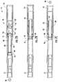
- FIGS. 1A-1Care cross-sectional views of one embodiment of a downhole tool constructed in accordance with the present invention.
- FIGS. 2A-2Care cross-sectional views of another embodiment of the downhole tool constructed in accordance with the present invention.
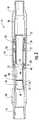
- FIG. 3is a cross-sectional view of yet another embodiment of the downhole tool constructed in accordance with the present disclosure.
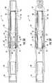
- FIGS. 4A and 4Bare cross-sectional views of the embodiment of the downhole tool shown in FIG. 3 in a second position and constructed in accordance with the present disclosure.
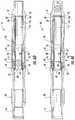
- FIGS. 5A and 5Bare cross-sectional views of the embodiment of the downhole tool shown in FIG. 3 in a third position and constructed in accordance with the present disclosure.
- FIG. 6Ais a cross-sectional view of another embodiment of the downhole tool shown in FIGS. 1A-1C constructed in accordance with the present invention.
- FIG. 6Bis a cross-sectional view of another embodiment of the downhole tool shown in FIGS. 2A-2C constructed in accordance with the present invention.
- FIGS. 6C-6Eare cross-sectional views of another embodiment of the downhole tool shown in FIGS. 3-5B constructed in accordance with the present invention.
- FIGS. 7A-7Care cross-sectional views of another embodiment of the downhole tool constructed in accordance with the present invention.
- FIGS. 8A and 8Bare close-up, cross-sectional views of a portion of the downhole tool shown in FIGS. 7A-7C and constructed in accordance with the present invention.
- FIGS. 9A-9Dare cross-sectional views of another embodiment of the downhole tool constructed in accordance with the present invention.
- FIGS. 10A-10Care cross-sectional views of another embodiment of a portion of the downhole tool constructed in accordance with the present invention.
- FIGS. 11A-11Care cross-sectional views of another embodiment of a portion of the downhole tool constructed in accordance with the present invention.
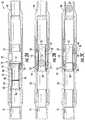
- the present disclosurerelates to a flapper valve tool 10 that can be designed and implemented into a bottom hole assembly (BHA) that has at least one sleeve disposed therein to either open a flapper 14 or permit the flapper 14 to close.
- BHAbottom hole assembly
- the flapper valve tool 10includes a top sub 16 for connecting to other tools disposed above the flapper valve tool 10 in the BHA, a bottom sub 18 for connecting the flapper valve tool 10 to other tools disposed below the flapper valve tool 10 in the BHA and a housing 20 (or body) connecting the top sub 16 to the bottom sub 18 .
- the flapper valve tool 10includes a closing sleeve 12 slidably disposed in the housing 20 and a flapper assembly 22 disposed in the housing 20 .
- the flapper assembly 22includes a flapper 14 for selectively blocking the backflow of fluid through the flapper valve tool 10 and a flapper seat 24 disposed in the housing 20 such that the closing sleeve 12 can slide through the flapper seat 24 .
- the flapper 14sits against the flapper seat 24 when the flapper 14 is in the closed position and prevents pressurized fluid from flowing in the uphole direction through the flapper valve tool 10 .
- the flapper 14can be hingedly connected to the flapper seat 24 or to the inside of the housing 20 .
- the closing sleeve 12 shown in FIGS. 1A-1Cincludes a collar 26 disposed around an outside portion of the closing sleeve 12 and the flapper valve tool 10 includes a shoulder 28 disposed therein to engage the collar 26 and prevent further sliding movement of the closing sleeve 12 when the closing sleeve 12 is shifted from a first position in the flapper valve tool 10 to a second position in the flapper valve tool 10 .
- the shoulder 28can be disposed on the inside of the bottom sub 18 or the housing 20 of the flapper valve tool 10 .
- the closing sleeve 12can be held in the first position in the flapper valve tool 10 via any means known in the art, such as shear pins 30 .
- the closing sleeve 12can also include a lip 32 disposed around a portion of the inside of the closing sleeve 12 to create a seat for a fluid blocking member 34 to engage and not be able to pass completely through the closing sleeve 12 .
- FIG. 1Ashows the closing sleeve 12 in its first position and holding the flapper 14 in an open position.
- FIG. 1Bshows the fluid blocking member 34 engaged with the lip 32 of the closing sleeve 12 and the closing sleeve 12 in its second position in the flapper valve tool 10 .
- the shear pins 30fail and permit the closing sleeve 12 to move from its first position to its second position in the flapper valve tool 10 .
- the closing sleeve 12will travel a predetermine distance before the collar 26 of the closing sleeve 12 impacts the shoulder 28 disposed on the inside of the flapper valve tool 10 , which prevents further movement of the closing sleeve 12 in the flapper valve tool 10 .
- the flapper 14is no longer prevented from closing and the flapper 14 closes against the flapper seat 24 to prevent fluid from flowing in the uphole direction through the flapper valve tool 10 .
- high pressure fluidcan be pumped down to force the fluid blocking member 34 past the lip 32 in the closing sleeve 12 , as can be seen in FIG. 1C .
- the flapper valve tool 10includes an opening sleeve 36 (as opposed to the closing sleeve 12 ) that has a first position where the flapper 14 is set against the flapper seat 24 (closed). Consequently, the flapper 14 is in the open position when the opening sleeve 36 is in its second position.
- the opening sleeve 36has a lip 38 disposed around an inner portion 40 of the opening sleeve 36 and a collar 42 disposed around an outer portion 44 of the opening sleeve 36 .
- the lip 38is designed to provide a seat for engaging with the fluid blocking member 34 .
- the collar 42is designed to engage with a shoulder 46 disposed within the flapper valve tool 10 .
- the collar 42is disposed on an uphole end 48 of the opening sleeve 36 to engage the shoulder 46 , which can be disposed on an inner portion of the housing 20 or a part of a flapper body 50 of the flapper assembly 22 .
- the opening sleeve 36can be held in place via shear pins 30 .
- FIG. 2Ashows the opening sleeve 36 in its first position wherein the flapper 14 is in the shut position and set against the flapper seat 24 restricting fluid from flowing in the uphole direction through the flapper valve tool 10 .
- FIG. 2Bshows the fluid blocking member 34 engaged with the lip 38 of the opening sleeve 36 and the opening sleeve 36 in its second position in the flapper valve tool 10 .
- the shear pins 30fail and permit the opening sleeve 36 to move from its first position to its second position in the flapper valve tool 10 .
- the opening sleeve 36will travel a predetermined distance before the collar 42 of the opening sleeve 36 impacts the shoulder 46 disposed on the inside of the flapper valve tool 10 , which prevents further movement of the opening sleeve 36 in the flapper valve tool 10 .
- a downhole end 52 of the opening sleeve 36contacts the flapper 14 and forces the flapper 14 into the open position as the opening sleeve 36 moves into its second position. This allows fluid to now flow in the uphole direction through the flapper valve tool 10 . If desired, high pressure fluid can be pumped down to force the fluid blocking member 34 past the lip 38 in the opening sleeve 36 as can be seen in FIG. 2C .
- the fluid blocking member 34can be pumped out of the flapper valve tool 10 and into some type of collection area so that fluid is permitted to flow in the uphole direction in the flapper valve tool 10 .
- the downhole end 52 of the opening sleeve 36can be angled such that opening the flapper 14 is significantly easier.
- the angle in the downhole end 52 of the opening sleeve 36is designed such that the longer portion of the opening sleeve 36 contacts the flapper 14 on the opposite side of the flapper 14 from where the flapper 14 is hinged.
- the flapper valve tool 10can be designed such that it has a first position where the flapper 14 is in an open position (see FIG. 3 ), a second position where the flapper 14 is in a closed position (see FIGS. 4A and 4B ) and a third position where the flapper 14 is back in the open position (see FIGS. 5A and 5B ).
- the flapper valve tool 10includes the top sub 16 , the bottom sub 18 and the housing 20 , as previously described herein.
- the flapper valve tool 10also includes the flapper assembly 22 , the closing sleeve 12 , and the opening sleeve 36 , as described herein.
- the closing sleeve 12is positioned downhole of the opening sleeve 36 in the flapper valve tool 10 .
- the flapper assembly 22can include the flapper 14 , the flapper seat 24 and the flapper body 50 , as previously described herein.
- the fluid blocking member 34is pumped into the flapper valve tool 10 to contact the lip 32 in the closing sleeve 12 .
- Fluidis pressured up behind the fluid blocking member 34 to shear pins 30 holding the closing sleeve 12 in the first position, which holds the flapper 14 in the open position.
- the closing sleeve 12is forced in the downhole direction inside the flapper valve tool 10 and into a second position for the closing sleeve 12 , as shown in FIGS. 4A and 4B . After the closing sleeve 12 travels a predetermined length inside the flapper valve tool 10 , the flapper 14 will spring shut against the flapper seat 24 .
- FIG. 4Bshows the closing sleeve 12 in the second position after the fluid blocking member 34 is pushed out of the closing sleeve 12 of the flapper valve tool 10 and the opening sleeve 36 in its first position.
- the fluid blocking member 34is sized such that it can pass by the lip 38 in the opening sleeve 36 and then engage the lip 32 in the closing sleeve 12 .
- a second fluid blocking member 54can be pumped down into the flapper valve tool 10 .
- the second fluid blocking member 54is pumped down and contacts the lip 38 in the opening sleeve 36 .
- the fluid in the flapper valve tool 10is pressured up and shear pins 30 holding the opening sleeve 36 in the opening sleeve's 36 first position are sheared, allowing the opening sleeve 36 to move in the downhole direction in the flapper valve tool 10 .
- the opening sleeve 36contacts the flapper 14 and forces it open.
- the opening sleeve 36prevents the flapper 14 from closing and maintains the flapper 14 in the open position, which is shown in FIG. 5 .
- FIG. 5Bshows the closing sleeve 12 in its second position and the opening sleeve 36 in its second position after the second fluid blocking member 54 was pushed out of the flapper valve tool 10 .
- the present disclosureis also directed toward a method of controlling the flapper valve tool 10 and the backflow of fluid from the BHA into any tubing or tubing string the BHA is attached to.
- the methodcan include placing the flapper valve tool 10 into a wellbore, activating the closing sleeve 12 or the opening sleeve 36 to close or open the flapper 14 , respectively.
- Activation of the closing sleeve 12 or the opening sleeve 36can be accomplished by pumping the fluid blocking members 34 , 54 into the flapper valve tool 10 to engage the lips 32 , 38 of the sleeves 12 , 36 .
- the flapper valve tool 10is placed in the wellbore and the closing sleeve 12 is shifted from its first position to its second position, which causes the flapper 14 to transition from an open position to a closed position.
- the opening sleeve 36can then be shifted from its first position to its second position, which causes the flapper 14 to transition from the closed position back to the open position.
- the flapper valve tool 10can include a deformable element that assists in the prevention of movement of the closing sleeve 12 and/or the opening sleeve 36 when they are in their second positions, respectively.
- the deformable elementscan also contribute to maintaining the flappers 14 in the open position.
- the deformable elementcan be disposed on the closing sleeve 12 and/or the opening sleeve 36 , the flapper 14 (flapper assembly 22 ) and/or other parts of the flapper valve tool 10 . It should be understood and appreciated that any flapper valve tool described herein can include a deformable element.
- FIGS. 6A-6Ethe lips 32 and 38 disposed on the closing sleeve 12 and the opening sleeve 36 are deformable.
- FIG. 6Ashows the result of the flapper valve tool 10 shown in FIG. 1B after the fluid blocking member 34 is forced past the lip 32 .
- a deformed portion 60is created in the closing sleeve 12 due to the force and pressure required to force the fluid blocking member 34 past the lip 32 in the closing sleeve 12 .
- the deformed portion 60 of the closing sleeve 12extends into a depression area 62 disposed on the inner portion of the housing 20 or bottom sub 18 and prevents the closing sleeve 12 from traveling in the uphole direction in the flapper valve tool 10 .
- FIG. 6Bshows the result of the flapper valve tool 10 shown in FIG. 2B after the fluid blocking member 34 is forced past the lip 38 , a deformed portion 64 is created in the opening sleeve 36 due to the force and pressure required to force the fluid blocking member 34 past the lip 38 in the opening sleeve 36 .
- the deformed portion 64 of the opening sleeve 36extends into a depression area 66 disposed on the inner portion of the housing 20 and adjacent to the flapper seat 24 .
- the deformed portion 64being wider than the flapper valve seat 24 prevents the opening sleeve 36 from traveling in the uphole direction in the flapper valve tool 10 .
- FIG. 6Cshows the result of the flapper valve tool 10 shown in FIG. 4B after the fluid blocking member 34 is forced past the lip 32 , the deformed portion 60 is created in the closing sleeve 12 due to the force and pressure required to force the fluid blocking member 34 past the lip 32 in the closing sleeve 12 .
- the deformed portion 60 of the closing sleeve 12extends into the depression area 62 disposed on the inner portion of the housing 20 or bottom sub 18 and prevents the closing sleeve 12 from traveling in the uphole direction in the flapper valve tool 10 .
- FIGS. 6D and 6Eshow the result of the flapper valve tool 10 shown in FIGS. 5A and 5B before and after the fluid blocking member 54 is forced past the lip 38 , the deformed portion 64 is created in the opening sleeve 36 due to the force and pressure required to force the fluid blocking member 54 past the lip 38 in the opening sleeve 36 .
- the deformed portion 64 of the opening sleeve 36extends into the depression area 66 disposed on the inner portion of the housing 20 and adjacent to the flapper seat 24 .
- the deformed portion 64being wider than the flapper valve seat 24 prevents the opening sleeve 36 from traveling in the uphole direction in the flapper valve tool 10 .
- the flapper valve tool 70includes a top sub 72 for connection to tools disposed above the flapper valve tool 70 , a bottom sub 74 for attachment of the flapper valve tool 70 to tools disposed below the flapper valve tool 70 , and a housing 76 disposed between the top sub 72 and the bottom sub 74 .
- the flapper valve tool 70further includes a flapper assembly 78 and a sleeve 80 slidably disposed within the housing 76 .
- the flapper assembly 78includes at least one flapper 82 (multiple flappers 82 can be implemented) for selectively blocking the backflow of fluid through the flapper valve tool 70 and a flapper seat 84 for each flapper 82 disposed in the housing 76 such that the sleeve 80 can slide through the flapper seat(s) 84 .
- the flapper 82sits against the flapper seat 84 when the flapper 82 is in the closed position and prevents pressurized fluid from flowing in the uphole direction through the flapper valve tool 70 .
- the flapper 82can be hingedly connected to the flapper seat 84 or to the inside of the housing 76 .
- the sleeve 80has a first position where the flapper 82 is set against the flapper seat 84 (closed). Consequently, the flapper 82 is in the open position when the sleeve 80 is in its second position.
- the sleeve 80has a collar 86 disposed around an outer portion 88 of the sleeve 80 .
- the collar 86is designed to engage with a shoulder 90 disposed within the flapper valve tool 70 .
- the collar 86is disposed on an uphole end 92 of the sleeve 80 to engage the shoulder 90 , which can be disposed on an inner portion of the housing 76 or a part of a flapper body 94 of the flapper assembly 78 .
- the sleeve 80includes a downhole end 94 that can be angled to more efficiently engage and open the flapper 82 .
- the flapper valve tool 70also includes a seat 96 engagable with the uphole end 92 of the sleeve 80 .
- the seat 96is constructed of an extrudable material and be dissolvable in a dissolving solution.
- the dissolving solutioncan include an acidic component.
- the seat 96can be designed such that a fluid blocking member 98 can be pumped into the flapper valve tool 70 and engage the seat 96 and prevent fluid from flowing through the flapper valve tool 70 .
- the pressure of the fluid in the flapper valve tool 70can be increased such that the engagement of the fluid blocking member 98 and the seat 96 causes the sleeve 80 to be shifted in the downhole direction in the flapper valve tool 70 .
- the design of the seat 96 and the uphole end 92 of the sleeve 80permits the fluid blocking member 98 to be passed through the flapper valve tool 70 when the pressure of the fluid is pressured up to a predetermined threshold.
- the collar 86 of the sleeve 80includes a recessed portion 100 on an internal part 102 of the collar 86 . Furthermore, the collar 86 includes a shoulder portion 104 that defines the downhole end of the collar 86 .
- the seat 96can have a main body 106 positioned adjacent to the uphole end 92 of the sleeve 80 and a sleeve element 108 extending from the main body 106 and into the collar 86 such that the sleeve element 108 is positioned adjacent to the internal part of the collar 86 . Furthermore, the seat 96 includes a lip 110 disposed on an inner surface 112 of the sleeve element 108 .
- the fluid blocking member 98is pumped down into the flapper valve tool 70 where it contacts the lip 110 of the seat 96 .
- Pressure of fluidis increased in the flapper valve tool 70 and the fluid blocking member 98 forces the seat 96 and the sleeve 80 to slide in the downhole direction in the flapper valve tool 70 .
- the pressure of the fluid in the flapper valve tool 70can be increased even further wherein the fluid blocking member 98 is forced past the seat 96 and out of the flapper valve tool 70 .
- the seat 96is deformable and the sleeve element 108 can be flexed radially outward into the recessed portion 100 of the collar 86 .
- a dissolving solutioncan then be passed through the flapper valve tool 70 to dissolve at least a portion of the seat 96 to widen the passageway through the seat 96 (see FIG. 8B ).
- the sleeve 80includes a recessed area 114 disposed adjacent to the shoulder 104 of the collar 86 .
- the recessed area 114engages a snap ring 115 which is statically disposed within the flapper valve tool 70 .
- the snap ring 115engages the recessed area 114 to prevent the sleeve 80 from shifting back in the uphole direction.
- the snap ring 115can be disposed adjacent to the flapper assembly 78 .
- the flapper valve tool 70includes a secondary flapper apparatus 116 disposed at least partially within the flapper valve tool 70 .
- the secondary flapper apparatus 116can include at least one secondary flapper 118 disposed therein to prevent fluid from flowing in the uphole direction through the flapper valve tool 70 when not desired.
- the secondary flapper apparatus 116can have a flapper housing 120 and a sleeve 122 extending therefrom in the uphole direction such that the sleeve 120 maintains the flappers 82 in an open position.
- the sleeve 122 and the secondary flappers 118allow fluid to flow through the flapper valve tool 70 in the downhole direction.
- the secondary flapper apparatus 116can be held in place in the housing 76 via shear pins 124 .
- the sleeve 122can have a propped end 126 that engages with at least one propped ball 128 disposed in an uphole end 130 of the flapper housing 120 to force the propped ball (s) 128 into a depression area 131 disposed on the inside of the housing 76 and a seat 132 disposed in an uphole end 134 of the sleeve 122 .
- the sleeve 122can also include a body 136 for engaging with the inside of the housing 76 and stabilizing the secondary flapper apparatus 116 in the housing 76 and a recessed area 138 disposed on the sleeve 122 between the body 136 and the propped end 126 .
- the secondary flapper apparatus 116can be configured to have a bottom sub portion so that the flapper valve tool 70 in this embodiment can be attached to other downhole tools downhole of the flapper valve tool 70 .
- the flapper valve tool 70can be used in a bottom hole assembly (BHA) and the BHA can be positioned adjacent to a terminal location in a horizontal well.
- a fluid blocking member 140can then be pumped down into the flapper valve tool 70 , passed through the sleeve 80 and contacted the seat 132 and prevent fluid from passing through the secondary flapper apparatus 116 .
- Pressure of the fluid in the flapper valve tool 70can then be pressured to a specific pressure threshold wherein the shear pins 124 shear and allow the sleeve 122 to slide in the downhole direction in the flapper valve tool 70 .
- the sliding of the sleeve 122causes the propped end 126 to slide in the flapper valve tool 70 and cease contact with the propped ball 128 allowing the propped ball 128 to disengage with the sleeve 122 and settle in an area adjacent to the recessed area 138 .
- the propped end 126 of the sleeve 122can then be forced to then end of a cavity area 142 disposed in the body 136 of the secondary flapper apparatus 116 wherein the secondary flapper apparatus 116 is then forced out of the flapper valve tool 70 .
- the flapper valve tool 70is then positioned at a desired location in the wellbore (e.g. at the heel).
- the fluid blocking member 98can then be pumped down into the flapper valve tool 70 to shift the sleeve 80 as previously described herein.
- the fluid blocking members 34 , 52 , 98 , 140can be constructed of a material that is dissolvable in specific types of fluid and/or well bore fluids.
- a solution capable of dissolving the fluid blocking members 34 , 52 , 98 , 140is pumped through the flapper valve tool 70 to dissolve the fluid blocking members 34 , 52 , 98 , 140 so that the fluid blocking members 34 , 52 , 98 , 140 will not hinder production of fluids (oil or gas) from the well.
- the fluid blocking members 34 , 52 , 98 , 140can be dissolved in the dissolving solution described above.
- the dissolving solutioncan be different for the fluid blocking members 34 , 52 , 98 , 140 or it can be the same.
- the dissolving solutioncan include an acidic solution.
- the flappers 14 , 82can include an opening 144 disposed therein to engage with a deformable pin element 146 extending from the flapper assembly 22 , 78 .
- fluidcan be passed through the flapper valve tool 10 , 70 and the opening 144 in the flappers 14 , 82 do not forcibly engage with the deformable pin element 146 of the flapper assembly 22 , 78 .
- the last fluid blocking member 34 , 52 , 98is passed through the flapper assembly 22 , 78 it forces the flapper open further and more forcibly.
- This more forcible openingcauses the deformable pin element 146 to be deformed and forced into the opening 144 .
- the deformation of the deformable pin element 146causes the deformable pin element 146 to remain in the opening 144 , which causes the flappers 14 , 82 to remain open.
- the flappers 14 , 82can include a deformable pin element 148 disposed thereon to engage with an opening 150 disposed in a portion of the flapper assembly 22 , 78 .
- fluidcan be passed through the flapper valve tool 10 , 70 and the deformable pin element 148 on the flappers 14 , 82 do not forcibly engage with the opening 150 disposed in the flapper assembly 22 , 78 .
- the last fluid blocking member 34 , 52 , 98is passed through the flapper assembly 22 , 78 it forces the flapper open further and more forcibly.
- This more forcible openingcauses the deformable pin element 148 to be deformed and forced into the opening 150 .
- the deformation of the deformable pin element 148causes the deformable pin element 148 to remain in the opening 150 , which causes the flappers 14 , 82 to remain open.
Landscapes
- Engineering & Computer Science (AREA)
- Life Sciences & Earth Sciences (AREA)
- Geology (AREA)
- Mining & Mineral Resources (AREA)
- Physics & Mathematics (AREA)
- Environmental & Geological Engineering (AREA)
- Fluid Mechanics (AREA)
- General Life Sciences & Earth Sciences (AREA)
- Geochemistry & Mineralogy (AREA)
- Mechanical Engineering (AREA)
- Lift Valve (AREA)
Abstract
Description
Claims (20)
Priority Applications (3)
| Application Number | Priority Date | Filing Date | Title |
|---|---|---|---|
| US15/989,332US11015407B2 (en) | 2014-08-15 | 2018-05-25 | Flapper valve tool |
| US16/178,063US10648260B2 (en) | 2014-08-15 | 2018-11-01 | Flapper valve tool |
| US16/802,002US10767444B2 (en) | 2014-08-15 | 2020-02-26 | Flapper valve tool |
Applications Claiming Priority (4)
| Application Number | Priority Date | Filing Date | Title |
|---|---|---|---|
| US201462038049P | 2014-08-15 | 2014-08-15 | |
| US14/615,237US9534460B2 (en) | 2014-08-15 | 2015-02-05 | Flapper valve tool |
| US15/058,887US10006261B2 (en) | 2014-08-15 | 2016-03-02 | Flapper valve tool |
| US15/989,332US11015407B2 (en) | 2014-08-15 | 2018-05-25 | Flapper valve tool |
Related Parent Applications (1)
| Application Number | Title | Priority Date | Filing Date |
|---|---|---|---|
| US15/058,887ContinuationUS10006261B2 (en) | 2014-08-15 | 2016-03-02 | Flapper valve tool |
Related Child Applications (2)
| Application Number | Title | Priority Date | Filing Date |
|---|---|---|---|
| US16/178,063ContinuationUS10648260B2 (en) | 2014-08-15 | 2018-11-01 | Flapper valve tool |
| US16/212,961ContinuationUS10619448B1 (en) | 2014-08-15 | 2018-12-07 | Flapper valve tool |
Publications (2)
| Publication Number | Publication Date |
|---|---|
| US20180274313A1 US20180274313A1 (en) | 2018-09-27 |
| US11015407B2true US11015407B2 (en) | 2021-05-25 |
Family
ID=56128836
Family Applications (3)
| Application Number | Title | Priority Date | Filing Date |
|---|---|---|---|
| US15/058,887Active2035-08-06US10006261B2 (en) | 2014-08-15 | 2016-03-02 | Flapper valve tool |
| US15/989,332ActiveUS11015407B2 (en) | 2014-08-15 | 2018-05-25 | Flapper valve tool |
| US16/178,063ActiveUS10648260B2 (en) | 2014-08-15 | 2018-11-01 | Flapper valve tool |
Family Applications Before (1)
| Application Number | Title | Priority Date | Filing Date |
|---|---|---|---|
| US15/058,887Active2035-08-06US10006261B2 (en) | 2014-08-15 | 2016-03-02 | Flapper valve tool |
Family Applications After (1)
| Application Number | Title | Priority Date | Filing Date |
|---|---|---|---|
| US16/178,063ActiveUS10648260B2 (en) | 2014-08-15 | 2018-11-01 | Flapper valve tool |
Country Status (1)
| Country | Link |
|---|---|
| US (3) | US10006261B2 (en) |
Families Citing this family (35)
| Publication number | Priority date | Publication date | Assignee | Title |
|---|---|---|---|---|
| US10502014B2 (en) | 2017-05-03 | 2019-12-10 | Coil Solutions, Inc. | Extended reach tool |
| WO2018204644A1 (en) | 2017-05-03 | 2018-11-08 | Coil Solutions, Inc. | Bit jet enhancement tool |
| US11199071B2 (en)* | 2017-11-20 | 2021-12-14 | Halliburton Energy Services, Inc. | Full bore buoyancy assisted casing system |
| US11384628B2 (en) | 2018-06-18 | 2022-07-12 | Schlumberger Technology Corporation | Open hole displacement with sacrificial screen |
| WO2020117229A1 (en) | 2018-12-05 | 2020-06-11 | Halliburton Energy Services, Inc. | Downhole apparatus |
| WO2020131076A1 (en)* | 2018-12-20 | 2020-06-25 | Halliburtion Energy Services, Inc. | Buoyancy assist tool |
| US11293261B2 (en) | 2018-12-21 | 2022-04-05 | Halliburton Energy Services, Inc. | Buoyancy assist tool |
| US10961797B2 (en) | 2019-04-05 | 2021-03-30 | Workover Solutions, Inc. | Integrated milling and production device |
| WO2020214145A1 (en) | 2019-04-15 | 2020-10-22 | Halliburton Energy Services, Inc. | Buoyancy assist tool with degradable nose |
| WO2020214154A1 (en) | 2019-04-16 | 2020-10-22 | Halliburton Energy Services, Inc. | Downhole apparatus with degradable plugs |
| WO2020226655A1 (en) | 2019-05-09 | 2020-11-12 | Halliburton Energy Services, Inc. | Downhole apparatus with removable plugs |
| WO2020242465A1 (en)* | 2019-05-29 | 2020-12-03 | Halliburton Energy Services, Inc. | Variable torque flapper valve |
| WO2020242464A1 (en)* | 2019-05-29 | 2020-12-03 | Halliburton Energy Services, Inc. | Flapper valve with beam spring |
| US11499395B2 (en)* | 2019-08-26 | 2022-11-15 | Halliburton Energy Services, Inc. | Flapper disk for buoyancy assisted casing equipment |
| US11105166B2 (en) | 2019-08-27 | 2021-08-31 | Halliburton Energy Services, Inc. | Buoyancy assist tool with floating piston |
| GB201912947D0 (en)* | 2019-09-09 | 2019-10-23 | Expro North Sea Ltd | Subsurface saftey valve and method of operating a subsurface saftey valve |
| US11072990B2 (en) | 2019-10-25 | 2021-07-27 | Halliburton Energy Services, Inc. | Buoyancy assist tool with overlapping membranes |
| US10995583B1 (en) | 2019-10-31 | 2021-05-04 | Halliburton Energy Services, Inc. | Buoyancy assist tool with debris barrier |
| US10989013B1 (en) | 2019-11-20 | 2021-04-27 | Halliburton Energy Services, Inc. | Buoyancy assist tool with center diaphragm debris barrier |
| US11230905B2 (en) | 2019-12-03 | 2022-01-25 | Halliburton Energy Services, Inc. | Buoyancy assist tool with waffle debris barrier |
| GB2605062B (en) | 2020-01-17 | 2024-09-25 | Halliburton Energy Services Inc | Voltage to accelerate/decelerate expandable metal |
| GB2604814B (en) | 2020-01-17 | 2024-10-09 | Halliburton Energy Services Inc | Heaters to accelerate setting of expandable metal |
| US11142994B2 (en) | 2020-02-19 | 2021-10-12 | Halliburton Energy Services, Inc. | Buoyancy assist tool with annular cavity and piston |
| US11359454B2 (en) | 2020-06-02 | 2022-06-14 | Halliburton Energy Services, Inc. | Buoyancy assist tool with annular cavity and piston |
| NO20230030A1 (en) | 2020-08-13 | 2023-01-12 | Halliburton Energy Services Inc | Expandable metal displacement plug |
| US11448040B2 (en)* | 2020-12-17 | 2022-09-20 | Halliburton Energy Services, Inc. | Fluid loss device including a self-opening upside down flapper valve |
| MX2023009992A (en) | 2021-04-12 | 2023-09-06 | Halliburton Energy Services Inc | Expandable metal as backup for elastomeric elements. |
| US12326060B2 (en) | 2021-05-21 | 2025-06-10 | Halliburton Energy Services, Inc. | Wellbore anchor including one or more activation chambers |
| NO20231087A1 (en) | 2021-05-28 | 2023-10-13 | Halliburton Energy Services Inc | Individual separate chunks of expandable metal |
| PL446571A1 (en) | 2021-05-28 | 2024-05-20 | Halliburton Energy Services, Inc. | Quick-setting, expandable metal |
| US12421824B2 (en) | 2021-05-29 | 2025-09-23 | Halliburton Energy Services, Inc. | Using expandable metal as an alternate to existing metal to metal seals |
| WO2022255988A1 (en) | 2021-06-01 | 2022-12-08 | Halliburton Energy Services, Inc. | Expanding metal used in forming support structures |
| US12378832B2 (en) | 2021-10-05 | 2025-08-05 | Halliburton Energy Services, Inc. | Expandable metal sealing/anchoring tool |
| US12305459B2 (en) | 2022-06-15 | 2025-05-20 | Halliburton Energy Services, Inc. | Sealing/anchoring tool employing an expandable metal circlet |
| US12385340B2 (en) | 2022-12-05 | 2025-08-12 | Halliburton Energy Services, Inc. | Reduced backlash sealing/anchoring assembly |
Citations (23)
| Publication number | Priority date | Publication date | Assignee | Title |
|---|---|---|---|---|
| US3289769A (en)* | 1964-05-15 | 1966-12-06 | Koehring Co | Well flow control device |
| US3995692A (en)* | 1974-07-26 | 1976-12-07 | The Dow Chemical Company | Continuous orifice fill device |
| US4469174A (en)* | 1983-02-14 | 1984-09-04 | Halliburton Company | Combination cementing shoe and basket |
| US4531587A (en) | 1984-02-22 | 1985-07-30 | Baker Oil Tools, Inc. | Downhole flapper valve |
| US4729432A (en) | 1987-04-29 | 1988-03-08 | Halliburton Company | Activation mechanism for differential fill floating equipment |
| US20020148615A1 (en)* | 2001-04-17 | 2002-10-17 | Szarka David D. | PDF valve |
| US20030047315A1 (en)* | 2001-09-11 | 2003-03-13 | Allamon Jerry P. | Float collar |
| US6679336B2 (en) | 2000-03-13 | 2004-01-20 | Davis-Lynch, Inc. | Multi-purpose float equipment and method |
| US6712150B1 (en) | 1999-09-10 | 2004-03-30 | Bj Services Company | Partial coil-in-coil tubing |
| US20040065442A1 (en) | 2002-10-03 | 2004-04-08 | Myerley Thomas S. | Lock open and control system access apparatus for a downhole safety valve |
| US20060207764A1 (en) | 2004-12-14 | 2006-09-21 | Schlumberger Technology Corporation | Testing, treating, or producing a multi-zone well |
| US20070295508A1 (en) | 2006-06-23 | 2007-12-27 | Frac Source Inc. | Shock-release fluid fracturing method and apparatus |
| WO2011005826A1 (en) | 2009-07-09 | 2011-01-13 | James Reaux | Surface controlled subsurface safety valve assembly with primary and secondary valves |
| US20110030968A1 (en) | 2009-08-10 | 2011-02-10 | Baker Hughes Incorporated | Tubular actuator, system and method |
| US20110073321A1 (en) | 2009-09-25 | 2011-03-31 | Baker Hughes Incorporated | Tubular actuator and method |
| US20110284232A1 (en)* | 2010-05-24 | 2011-11-24 | Baker Hughes Incorporated | Disposable Downhole Tool |
| US20110290344A1 (en) | 2010-05-24 | 2011-12-01 | Blackhawk Specialty Tools, Llc | Large bore auto-fill float equipment |
| WO2012048144A2 (en) | 2010-10-06 | 2012-04-12 | Colorado School Of Mines | Downhole tools and methods for selectively accessing a tubular annulus of a wellbore |
| US8291988B2 (en) | 2009-08-10 | 2012-10-23 | Baker Hughes Incorporated | Tubular actuator, system and method |
| US8646531B2 (en) | 2009-10-29 | 2014-02-11 | Baker Hughes Incorporated | Tubular actuator, system and method |
| US20140069654A1 (en) | 2010-10-21 | 2014-03-13 | Peak Completion Technologies, Inc. | Downhole Tool Incorporating Flapper Assembly |
| US20140158361A1 (en)* | 2012-12-07 | 2014-06-12 | CNPC USA Corp. | Pressure controlled multi-shift frac sleeve system |
| US20140202713A1 (en)* | 2013-01-18 | 2014-07-24 | Halliburton Energy Services, Inc. | Well Intervention Pressure Control Valve |
Family Cites Families (1)
| Publication number | Priority date | Publication date | Assignee | Title |
|---|---|---|---|---|
| US9279310B2 (en)* | 2013-01-22 | 2016-03-08 | Halliburton Energy Services, Inc. | Pressure testing valve and method of using the same |
- 2016
- 2016-03-02USUS15/058,887patent/US10006261B2/enactiveActive
- 2018
- 2018-05-25USUS15/989,332patent/US11015407B2/enactiveActive
- 2018-11-01USUS16/178,063patent/US10648260B2/enactiveActive
Patent Citations (25)
| Publication number | Priority date | Publication date | Assignee | Title |
|---|---|---|---|---|
| US3289769A (en)* | 1964-05-15 | 1966-12-06 | Koehring Co | Well flow control device |
| US3995692A (en)* | 1974-07-26 | 1976-12-07 | The Dow Chemical Company | Continuous orifice fill device |
| US4469174A (en)* | 1983-02-14 | 1984-09-04 | Halliburton Company | Combination cementing shoe and basket |
| US4531587A (en) | 1984-02-22 | 1985-07-30 | Baker Oil Tools, Inc. | Downhole flapper valve |
| US4729432A (en) | 1987-04-29 | 1988-03-08 | Halliburton Company | Activation mechanism for differential fill floating equipment |
| US6712150B1 (en) | 1999-09-10 | 2004-03-30 | Bj Services Company | Partial coil-in-coil tubing |
| US6679336B2 (en) | 2000-03-13 | 2004-01-20 | Davis-Lynch, Inc. | Multi-purpose float equipment and method |
| US20020148615A1 (en)* | 2001-04-17 | 2002-10-17 | Szarka David D. | PDF valve |
| US20030047315A1 (en)* | 2001-09-11 | 2003-03-13 | Allamon Jerry P. | Float collar |
| US6712145B2 (en)* | 2001-09-11 | 2004-03-30 | Allamon Interests | Float collar |
| US20040065442A1 (en) | 2002-10-03 | 2004-04-08 | Myerley Thomas S. | Lock open and control system access apparatus for a downhole safety valve |
| US20060207764A1 (en) | 2004-12-14 | 2006-09-21 | Schlumberger Technology Corporation | Testing, treating, or producing a multi-zone well |
| US20070295508A1 (en) | 2006-06-23 | 2007-12-27 | Frac Source Inc. | Shock-release fluid fracturing method and apparatus |
| WO2011005826A1 (en) | 2009-07-09 | 2011-01-13 | James Reaux | Surface controlled subsurface safety valve assembly with primary and secondary valves |
| US20110030968A1 (en) | 2009-08-10 | 2011-02-10 | Baker Hughes Incorporated | Tubular actuator, system and method |
| US8291988B2 (en) | 2009-08-10 | 2012-10-23 | Baker Hughes Incorporated | Tubular actuator, system and method |
| US20110073321A1 (en) | 2009-09-25 | 2011-03-31 | Baker Hughes Incorporated | Tubular actuator and method |
| US8646531B2 (en) | 2009-10-29 | 2014-02-11 | Baker Hughes Incorporated | Tubular actuator, system and method |
| US20110284232A1 (en)* | 2010-05-24 | 2011-11-24 | Baker Hughes Incorporated | Disposable Downhole Tool |
| US20110290344A1 (en) | 2010-05-24 | 2011-12-01 | Blackhawk Specialty Tools, Llc | Large bore auto-fill float equipment |
| WO2012048144A2 (en) | 2010-10-06 | 2012-04-12 | Colorado School Of Mines | Downhole tools and methods for selectively accessing a tubular annulus of a wellbore |
| US20120085548A1 (en)* | 2010-10-06 | 2012-04-12 | Colorado School Of Mines | Downhole Tools and Methods for Selectively Accessing a Tubular Annulus of a Wellbore |
| US20140069654A1 (en) | 2010-10-21 | 2014-03-13 | Peak Completion Technologies, Inc. | Downhole Tool Incorporating Flapper Assembly |
| US20140158361A1 (en)* | 2012-12-07 | 2014-06-12 | CNPC USA Corp. | Pressure controlled multi-shift frac sleeve system |
| US20140202713A1 (en)* | 2013-01-18 | 2014-07-24 | Halliburton Energy Services, Inc. | Well Intervention Pressure Control Valve |
Non-Patent Citations (2)
| Title |
|---|
| PCT/US2015/014972; International Search Report and Written Opinion; dated May 14, 2015; 16 pages. |
| PCT/US2016/020477; International Search Report and Written Opinion; dated Nov. 25, 2016; 18 pages. |
Also Published As
| Publication number | Publication date |
|---|---|
| US20160177668A1 (en) | 2016-06-23 |
| US20190071942A1 (en) | 2019-03-07 |
| US20180274313A1 (en) | 2018-09-27 |
| US10006261B2 (en) | 2018-06-26 |
| US10648260B2 (en) | 2020-05-12 |
Similar Documents
| Publication | Publication Date | Title |
|---|---|---|
| US11015407B2 (en) | Flapper valve tool | |
| US10767444B2 (en) | Flapper valve tool | |
| US10648288B2 (en) | Flapper valve tool | |
| WO2017151126A1 (en) | Flapper valve tool | |
| US10526865B2 (en) | Annular barrier with closing mechanism | |
| US10563476B2 (en) | Frac plug with integrated flapper valve | |
| US8479808B2 (en) | Downhole tools having radially expandable seat member | |
| US8550176B2 (en) | Wellbore bypass tool and related methods of use | |
| AU2017272226A1 (en) | Valve for hydraulic fracturing through cement outside casing | |
| US8820418B2 (en) | Differential shifting tool and method of shifting | |
| US20140318815A1 (en) | Actuator ball retriever and valve actuation tool | |
| US11203917B2 (en) | Equalizing device for safety valves | |
| US10422202B2 (en) | Linearly indexing wellbore valve | |
| US9835010B2 (en) | Toe valve | |
| NO20171719A1 (en) | An improved drill string safety valve device | |
| US8973663B2 (en) | Pump through circulating and or safety circulating valve |
Legal Events
| Date | Code | Title | Description |
|---|---|---|---|
| AS | Assignment | Owner name:THRU TUBING SOLUTIONS, INC., OKLAHOMA Free format text:ASSIGNMENT OF ASSIGNORS INTEREST;ASSIGNORS:WATSON, BROCK;SCHULTZ, ROGER;FERGUSON, ANDY;REEL/FRAME:045901/0165 Effective date:20180523 | |
| FEPP | Fee payment procedure | Free format text:ENTITY STATUS SET TO UNDISCOUNTED (ORIGINAL EVENT CODE: BIG.); ENTITY STATUS OF PATENT OWNER: LARGE ENTITY | |
| STPP | Information on status: patent application and granting procedure in general | Free format text:RESPONSE AFTER FINAL ACTION FORWARDED TO EXAMINER | |
| STPP | Information on status: patent application and granting procedure in general | Free format text:ADVISORY ACTION MAILED | |
| STCB | Information on status: application discontinuation | Free format text:ABANDONED -- FAILURE TO RESPOND TO AN OFFICE ACTION | |
| STPP | Information on status: patent application and granting procedure in general | Free format text:NON FINAL ACTION MAILED | |
| STPP | Information on status: patent application and granting procedure in general | Free format text:RESPONSE TO NON-FINAL OFFICE ACTION ENTERED AND FORWARDED TO EXAMINER | |
| STPP | Information on status: patent application and granting procedure in general | Free format text:FINAL REJECTION MAILED | |
| STPP | Information on status: patent application and granting procedure in general | Free format text:ADVISORY ACTION MAILED | |
| STPP | Information on status: patent application and granting procedure in general | Free format text:NOTICE OF ALLOWANCE MAILED -- APPLICATION RECEIVED IN OFFICE OF PUBLICATIONS | |
| STPP | Information on status: patent application and granting procedure in general | Free format text:PUBLICATIONS -- ISSUE FEE PAYMENT RECEIVED | |
| STPP | Information on status: patent application and granting procedure in general | Free format text:PUBLICATIONS -- ISSUE FEE PAYMENT VERIFIED | |
| STCF | Information on status: patent grant | Free format text:PATENTED CASE | |
| MAFP | Maintenance fee payment | Free format text:PAYMENT OF MAINTENANCE FEE, 4TH YEAR, LARGE ENTITY (ORIGINAL EVENT CODE: M1551); ENTITY STATUS OF PATENT OWNER: LARGE ENTITY Year of fee payment:4 |