US11014532B2 - Vehicle control module for smart home control system - Google Patents
Vehicle control module for smart home control systemDownload PDFInfo
- Publication number
- US11014532B2 US11014532B2US16/402,540US201916402540AUS11014532B2US 11014532 B2US11014532 B2US 11014532B2US 201916402540 AUS201916402540 AUS 201916402540AUS 11014532 B2US11014532 B2US 11014532B2
- Authority
- US
- United States
- Prior art keywords
- vehicle
- control
- location
- status
- request
- Prior art date
- Legal status (The legal status is an assumption and is not a legal conclusion. Google has not performed a legal analysis and makes no representation as to the accuracy of the status listed.)
- Active
Links
- 238000004891communicationMethods0.000claimsabstractdescription56
- 238000000034methodMethods0.000claimsdescription33
- 230000004044responseEffects0.000claimsdescription24
- 238000012790confirmationMethods0.000claims2
- 238000001514detection methodMethods0.000claims2
- 239000000446fuelSubstances0.000description7
- 230000008569processEffects0.000description7
- 230000007246mechanismEffects0.000description6
- 238000010586diagramMethods0.000description5
- 230000000007visual effectEffects0.000description4
- 238000012423maintenanceMethods0.000description3
- 230000008901benefitEffects0.000description2
- 238000012986modificationMethods0.000description2
- 230000004048modificationEffects0.000description2
- 235000013550pizzaNutrition0.000description2
- 230000010267cellular communicationEffects0.000description1
- 230000008859changeEffects0.000description1
- 239000003086colorantSubstances0.000description1
- 230000008878couplingEffects0.000description1
- 238000010168coupling processMethods0.000description1
- 238000005859coupling reactionMethods0.000description1
- 210000003195fasciaAnatomy0.000description1
- 235000013305foodNutrition0.000description1
- 230000006870functionEffects0.000description1
- 238000010438heat treatmentMethods0.000description1
- 230000003287optical effectEffects0.000description1
Images

Classifications
- B—PERFORMING OPERATIONS; TRANSPORTING
- B60—VEHICLES IN GENERAL
- B60R—VEHICLES, VEHICLE FITTINGS, OR VEHICLE PARTS, NOT OTHERWISE PROVIDED FOR
- B60R25/00—Fittings or systems for preventing or indicating unauthorised use or theft of vehicles
- B60R25/01—Fittings or systems for preventing or indicating unauthorised use or theft of vehicles operating on vehicle systems or fittings, e.g. on doors, seats or windscreens
- B60R25/04—Fittings or systems for preventing or indicating unauthorised use or theft of vehicles operating on vehicle systems or fittings, e.g. on doors, seats or windscreens operating on the propulsion system, e.g. engine or drive motor
- B60R25/042—Fittings or systems for preventing or indicating unauthorised use or theft of vehicles operating on vehicle systems or fittings, e.g. on doors, seats or windscreens operating on the propulsion system, e.g. engine or drive motor operating on the fuel supply
- B—PERFORMING OPERATIONS; TRANSPORTING
- B60—VEHICLES IN GENERAL
- B60R—VEHICLES, VEHICLE FITTINGS, OR VEHICLE PARTS, NOT OTHERWISE PROVIDED FOR
- B60R25/00—Fittings or systems for preventing or indicating unauthorised use or theft of vehicles
- B60R25/20—Means to switch the anti-theft system on or off
- B60R25/209—Remote starting of engine
- B—PERFORMING OPERATIONS; TRANSPORTING
- B60—VEHICLES IN GENERAL
- B60R—VEHICLES, VEHICLE FITTINGS, OR VEHICLE PARTS, NOT OTHERWISE PROVIDED FOR
- B60R25/00—Fittings or systems for preventing or indicating unauthorised use or theft of vehicles
- B60R25/01—Fittings or systems for preventing or indicating unauthorised use or theft of vehicles operating on vehicle systems or fittings, e.g. on doors, seats or windscreens
- B—PERFORMING OPERATIONS; TRANSPORTING
- B60—VEHICLES IN GENERAL
- B60R—VEHICLES, VEHICLE FITTINGS, OR VEHICLE PARTS, NOT OTHERWISE PROVIDED FOR
- B60R25/00—Fittings or systems for preventing or indicating unauthorised use or theft of vehicles
- B60R25/20—Means to switch the anti-theft system on or off
- B—PERFORMING OPERATIONS; TRANSPORTING
- B60—VEHICLES IN GENERAL
- B60W—CONJOINT CONTROL OF VEHICLE SUB-UNITS OF DIFFERENT TYPE OR DIFFERENT FUNCTION; CONTROL SYSTEMS SPECIALLY ADAPTED FOR HYBRID VEHICLES; ROAD VEHICLE DRIVE CONTROL SYSTEMS FOR PURPOSES NOT RELATED TO THE CONTROL OF A PARTICULAR SUB-UNIT
- B60W30/00—Purposes of road vehicle drive control systems not related to the control of a particular sub-unit, e.g. of systems using conjoint control of vehicle sub-units
- B60W30/18—Propelling the vehicle
- B60W30/188—Controlling power parameters of the driveline, e.g. determining the required power
- B—PERFORMING OPERATIONS; TRANSPORTING
- B60—VEHICLES IN GENERAL
- B60T—VEHICLE BRAKE CONTROL SYSTEMS OR PARTS THEREOF; BRAKE CONTROL SYSTEMS OR PARTS THEREOF, IN GENERAL; ARRANGEMENT OF BRAKING ELEMENTS ON VEHICLES IN GENERAL; PORTABLE DEVICES FOR PREVENTING UNWANTED MOVEMENT OF VEHICLES; VEHICLE MODIFICATIONS TO FACILITATE COOLING OF BRAKES
- B60T2220/00—Monitoring, detecting driver behaviour; Signalling thereof; Counteracting thereof
- B60T2220/02—Driver type; Driving style; Driver adaptive features
Definitions
- the present inventiongenerally relates to a remote control system of a vehicle, and more particularly, to a vehicle-based remote control system for controlling one or more smart devices located remotely from the vehicle.
- a control module for a vehiclecomprises a wireless communication circuit in communication with a smart home device and a remote server.
- the control modulefurther comprises a control circuit in communication with the wireless communication circuit and a controller of the vehicle via a bus interface.
- the control circuitis configured to receive a status request from the smart home device via the wireless communication circuit. Based on the status request, the control circuit requests a status identification from the controller according to the status request.
- the control circuitreceives the status identification from the controller and communicates the status identification to the smart device via the wireless communication circuit. The status identification is announced by the smart home device.
- a method for communicating a status inquiry of a vehiclecomprises receiving a status request from the smart home device via the wireless communication circuit and requesting a status identification from a controller of the vehicle according to the status request.
- the methodfurther comprises receiving the status identification from the controller and communicating the status identification to the smart device via the wireless communication circuit. The status identification may then be indicated by the smart home device.
- a control system for a vehiclecomprises a wireless communication circuit in communication with a smart home device and a remote server and a control circuit in communication with the wireless communication circuit and a controller of the vehicle.
- the control circuitis in communication with the controller of the vehicle via a bus interface.
- the control circuitis configured to receive a control request from the smart home device via the wireless communication circuit, the control request comprises an authentication indication and requests an update of a state of at least one system of the vehicle according to the control request.
- the controlleris further configured to receive an identification of the state from the controller in response to the request of the update, and communicate the identification of the state to the smart device via the wireless communication circuit.
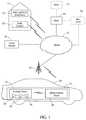
- FIG. 1is a block diagram showing a vehicle-based control system in communication with a server responsive to voice commands according to embodiments of the present invention
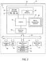
- FIG. 2is a block diagram showing the vehicle-based control system in greater detail
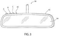
- FIG. 3is a front perspective view of a rearview mirror assembly incorporating an in-vehicle device of the vehicle-based control system
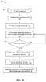
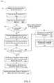
- FIG. 4is a flow diagram of a method for a control module of a vehicle configured to communicate a status message to a smart home system
- FIG. 5is a flow diagram of a method for a control module of a vehicle configured to control a vehicle system or accessory in accordance with the disclosure.
- the term “and/or,” when used in a list of two or more items,means that any one of the listed items can be employed by itself, or any combination of two or more of the listed items can be employed.
- the compositioncan contain A alone; B alone; C alone; A and B in combination; A and C in combination; B and C in combination; or A, B, and C in combination.
- the vehicle-based remote control systemmay be configured to communicate with one or more remote control devices or smart devices.
- the remote control systemmay be configured to communicate with the smart devices to supply vehicle information to the smart devices and/or receive control instructions from the smart devices.
- the vehicle-based remote control systemmay be configured to receive a control instruction based on a voice command of a smart device.
- the vehicle-based remote control systemmay be configured to communicate information to the smart device or control one or more vehicle systems (e.g., an alarm, ignition, door lock, door latch, widow controller, etc.).
- vehicle systemse.g., an alarm, ignition, door lock, door latch, widow controller, etc.
- a diagram of a voice-controlled smart device 10is shown located inside a home 12 .
- the device 10may correspond to a Home or Home Mini sold by Google, or an Echo or Echo Dot sold by Amazon. Though specific devices are discussed in reference to the smart device 10 , various devices with similar functionality may be implemented in accordance with the disclosure.
- the smart device 10may include a built-in microphone and speaker and be utilized as hands-free, voice-controlled devices that use a virtual assistant (e.g., Alexa or Google Assistant). In operation, the device 10 continuously listens for a wake word (e.g., “OK Google” or “Alexa”) to be spoken by a user.
- a wake worde.g., “OK Google” or “Alexa
- the device 10recognizes that the wake word has been said and begins recording a user voice command.
- device 10sends the recording over the internet 14 to a server 16 , such as Google Services or Alexa Voice Services (AVS).
- the server 16may correspond to a cloud-based service operated by Google, Amazon, or other providers.
- the server 16processes the recording and generates a command sent over the internet 14 to device 10 .
- the device 10receives the command and implements a task consistent with the user voice command originally spoken by the user. For example, if the user said “Alexa, what is the weather today?”, Alexa may respond via the speaker in the smart device 10 with a general forecast related to the geographical area of the user.
- device 10may be linked to one or more compatible smart devices 18 , such as any of those produced by Samsung SmartThings®, Wink, Insteon®, Nest®, Philips Hue, Wemo®, Ecobee®, for example.
- the server 16may be able to generate commands for controlling one or more of the devices 18 in response to a complimentary user voice command recording(s). For example, when server 16 receives a user voice command related to the control of a linked device, such as one of devices 18 , the server 16 may parse the user voice command before sending it to another server 19 in charge of the linked device. That server 19 would, in turn, generate a command in accordance with the user voice command. Alternatively, it is contemplated that server 16 may generate a command for directly controlling the linked device, if such functionality permits.
- the smart device 10may enable a user to not only request information on demand, but also automate various home features in response to a user voice command. Such features may include lights, thermostats, speakers, sprinklers, fans, and televisions, for example.
- device 10may be configured such that a user voice command results in the server 16 generating a command that is transmitted over the internet 14 to a web-based service provider 20 for prompting the same to render a service.
- the smart device 10may be operable to generate computerized orders for a user to order food from restaurants or items through online shopping providers (e.g., pizza from Domino's pizza, merchandise from Amazon, or a shuttle vehicle from Uber).
- online shopping providerse.g., pizza from Domino's pizza, merchandise from Amazon, or a shuttle vehicle from Uber.
- the remote control system 22may be configured to communicate with the server 16 .
- the remote control system 22may be operable to enable a user, typically a vehicle occupant (e.g., the driver), to remotely control the smart device 10 and/or devices 18 linked thereto.
- the remote control system 22may include a first device and/or a second device.
- the first devicemay correspond to a dedicated user interface for a control module 24 , which may be incorporated in a vehicle 26 .
- the second devicemay correspond to a mobile electronic device 28 , generally located inside a vehicle 26 .
- the control module 24 of the remote control system 22may be configured to work in coordination with the smart device 10 to communicate with and control various systems of the vehicle 26 .
- the control module 24may be configured to communicate vehicle information to the smart device 10 and/or receive control instructions from the smart device 10 .
- the vehicle-based remote control system 22may be configured to receive a control instruction based on a voice command of a smart device 10 .
- the vehicle-based remote control system 22may be configured to communicate information to the smart device 10 or control one or more vehicle systems (e.g., an alarm, ignition, door lock, door latch, widow controller, etc.).
- vehicle systemse.g., an alarm, ignition, door lock, door latch, widow controller, etc.
- the control module 24may include a user-input mechanism 32 , an interface 34 configured to communicate with the mobile electronic device 28 , and a controller 36 coupled to the user-input mechanism 32 and the interface 34 .
- the user-input mechanism 32may include one or more actuatable members, exemplarily shown as buttons A, B, and C. While three buttons are shown, it is to be understood that more or less buttons may be provided, if desired.
- the actuatable membersmay be embodied as toggle switches, capacitive sensors, optical sensors, or any other component capable of registering user actuation.
- the user-input mechanism 32may be associated with a user interface 38 that also includes one or more visual indicators 40 for providing feedback in response to actuation of the user-input mechanism 32 .
- the interface 34may include a wireless communication transceiver 42 for enabling the controller 36 to wirelessly communicate with the mobile electronic device 28 .
- the wireless communication transceiver 42may be configured such that communication between the controller 36 and the mobile electronic device 28 occurs via Bluetooth®, Bluetooth® Low Energy, Wi-Fi®, or any other known wireless communication protocol.
- the interface 34may include a vehicle bus interface 44 connected to a vehicle bus 44 for enabling the controller 36 to communicate with the mobile electronic device 28 via a USB connection or other known wired connection.
- the vehicle bus 44may also connect to various vehicle equipment including, for example, a vehicle navigation system 48 (e.g. GPS Navigation), a light sensor 49 , and a vehicle sound system 50 .
- the vehicle bus 44may further be in communication with additional vehicle control systems including, but not limited to, a security system, ignition system, fuel level indicator, door lock, door latch, widow controller, etc.
- control module 24may be in communication with a vehicle controller via the vehicle bus 46 .
- control module 24may be configured to communicate with the control module 24 to identify various status conditions of the vehicle 26 .
- control module 24may be configured to identify one or more vehicle status conditions (e.g., an engine warning, oil warning, maintenance schedule, tire pressure indication, airbag operation warning, or any other status indications identifiable by the vehicle controller).
- a usermay request a status update via the voice-controlled smart device 10 by stating, “OK Google, provide a status for vehicle 1 .”
- the smart device 10may transmit the instruction to the server 16 , which may identify an instruction and communicate with the control module 24 of the vehicle via a wireless communication interface 30 .
- the wireless communication interface 30may include various communication protocols compatible with a wireless transceiver of the remote control system 22 which may include but are not limited to WiFi (802.11 series—802.11g, 802.11b, 802.11a, 802.11n, etc.), Bluetooth®, Ultra-wideband (UWB), ZigBee®, cellular communications (3G, 4G, LTE), etc.
- the control module 24may communicate with the vehicle controller via a communication bus to identify whether a status indication (e.g., maintenance, low fuel, tire pressure, check engine, active, inactive, etc.) exists for the vehicle 26 .
- the control module 24may then communicate the status of the vehicle 26 to the voice-controlled smart device 10 via the communication interface 30 .
- the voice-controlled smart device 10may announce the status of vehicle 1 .
- the smart device 10may output an audible indication announcing the vehicle status or warning status for the vehicle 26 .
- a preconfigured or computer generated voicemay announce via the speakers of the smart device 10 : “Vehicle 1 is inactive and does not have any status indications,” “vehicle is inactive and indicates that the fuel level is low,” “vehicle is active and requires an oil change,” etc.
- the remote control system 22may be configured to communicate a condition of the vehicle 26 to the voice-controlled smart device 10 in response to a user request.
- the control module 24may further be configured to provide an identification of a heading and/or location of the vehicle 26 .
- a user of the smart device 10may request a location update for the vehicle 26 by saying, “smart device, wherein is vehicle 1 ?”
- the smart device 10may communicate the request to the control module 24 .
- the control module 24may communicate with a location device (e.g. the navigation system 48 ) to identify a current location of the vehicle 26 . Once the location is identified, the control module 24 may communicate the location back to the smart device 10 .
- the location of the vehicle 26may be announced via the speaker of the smart device 10 by announcing a corresponding address or nearby landmark.
- a nearby landmarkmay be identified by the server 16 and the smart home device 10 may output the location of the vehicle relative to the landmark.
- the smart device 10may output: “vehicle 1 is parked near store A in City B,” or “vehicle 1 is driving in direction A (e.g. north) near store C on Street D in City F.”
- the control module 24may provide the smart home device 10 with information identifying the location of the vehicle 26 such that the smart home device 10 can announce the information to an authorized user.
- the second devicemay correspond to the mobile electronic device 28 , which may be utilized in combination with the control module 24 to communicate information to and from the communication interface 30 .
- the mobile electronic device 28may be a smartphone, tablet, or the like, or may, alternatively, be a dedicated device integrated with the vehicle or portable in nature.
- the control module 24may communicate with the mobile electronic device 28 via a wired or wireless communication interface 30 as discussed herein.
- the control module 24may be integrated within the vehicle 26 and may receive power from the vehicle battery and/or vehicle ignition.
- the control module 24may be one of several HOMELINK® devices available from Gentex Corporation of Zeeland, Mich. Such devices may, for example, be integrated with a rearview mirror assembly, a sun visor, or a vehicle console such as an overhead console.
- the control module 24may be incorporated in the mirror assembly 60 .
- the rearview mirror assembly 60may include a housing 62 for mounting to the vehicle 26 , and a rearview device 64 such as a rearview mirror element, a rearview display, or combination thereof.
- buttons A, B, and C of the user-input mechanism 32are exemplarily located proximate a top corner portion of the housing 62 along with visual indicator 40 .
- buttons A, B, and Cmay be elsewhere located, such as, for example, on a front fascia of the rearview mirror assembly 60 .
- buttons A, B, and Cmay be provided in vehicle equipment such as, but not limited to, a center console, an overhead console, and the like.
- Visual indicator 40may be operated to provide visual feedback in response to an executed command and may take the form of an LED indicator light capable of illuminating in one or more colors.
- the methodmay begin by receiving a request at the smart device 10 for a status identification ( 82 ).
- the smart device 10may then communicate the status identification request to the server 16 ( 84 ).
- the control module 24may then receive the status request from the server 16 via the communication interface 30 ( 86 ).
- the control module 24may communicate with the vehicle controller via the vehicle bus interface 44 to identify status of vehicle 26 ( 88 ).
- the vehicle statusmay correspond to an engine warning, oil warning, maintenance schedule, tire pressure indication, airbag operation warning, or any other status indications identifiable by the vehicle controller.
- the status identificationmay correspond to a security system status, ignition system status, fuel level indication, door lock status, door latch status, widow position status, etc.
- the request for the status identificationmay be specifically directed to any of these indications.
- Such a status identificationmay be prompted by a specific request to the smart device 10 . For example, in response to, “smart device, what is the fuel level of vehicle 1 ?”, the smart device may request an indication of the vehicle status in the form of the fuel level of the vehicle 26 . Accordingly, in step 88 , the control module 24 may communicate with the vehicle controller via the vehicle bus interface 44 to identify the fuel level of vehicle 1 .
- the control module 24may continue to send the status indication to the server 16 via the communication interface 30 ( 92 ). If the vehicle status is not identified in step 90 , the control module 24 may continue to communicate with the vehicle controller until an error state is entered after repeated failures. The error state may be communicated to the smart device 10 via the communication interface 30 or may be identified by the smart device 10 after a timeout period has expired. Following step 92 , the status identification of the vehicle 26 may be communicated from the server 16 back to the voice-controlled smart device 10 ( 94 ). The voice-controlled smart device 10 may then output a message identifying the status communicated in the status identification for the vehicle 26 ( 96 ). In reference to FIG. 5 , a similar method is described that also provides for an authentication procedure. Such an authentication procedure may similarly be applied to the method 80 in accordance with the disclosure.
- the method 100may begin by receiving a request at the smart device 10 ( 102 ). However, the request in the method 100 may be in order to control a system or accessory of the vehicle 26 . Upon receiving the request, the smart device 10 may communicate the vehicle control request to the server 16 ( 104 ). Once the request is received, the server 16 may authenticate the request for control of the vehicle 26 ( 106 ). The authentication may ensure that the user requesting control of the vehicle 26 is authorized to control the vehicle 26 as requested. The user may be authenticated via voice recognition, a spoken code or code word, or various combinations of voice authentication with specific codes or passwords, which may be prompted by the smart device 10 .
- the server 16may communicate a message denying authentication for the user to control the vehicle 26 to the smart device 10 ( 110 ). The smart device 10 may then output a message from the speakers indicating that the control of the vehicle 26 is denied ( 112 ). If the request to control the vehicle 26 is authenticated in step 108 , the server 16 may communicate the control request to the control module 24 via the communication interface 30 ( 114 ). In response to receiving the control request, the control module 24 may communicate with the vehicle controller via the vehicle bus interface 44 to control the system or accessory of the vehicle 26 as requested ( 116 ). The control module 24 may then continue to verify whether or not the control request for the vehicle 26 is completed in step 118 .
- control module 24may continue to step 110 . If the vehicle control request is successfully completed, the control module 24 may communicate a status signal identifying the completion of the control of the vehicle 26 to the server 16 via the communication interface ( 120 ). The server 16 may then communicate the status indication of the vehicle control request to the smart device 10 ( 122 ). In response to receiving the status indication, the smart device 10 may be configured to output a message from the speakers identifying the status of the control instruction for the vehicle 26 as being complete ( 124 ).
- the vehicle control instruction as discussed hereinmay correspond to various forms of requests to control various vehicle systems and accessories.
- the controlmay be configured to the following exemplary vehicle systems without limitation: an ignition system, a lighting system, a horn or alarm system, a door lock system, one or more automated or power doors, a climate control or heating system, a defrost system, etc.
- a single commandmay be configured to control more than one of the vehicles systems or accessories. For example, “smart home, prepare vehicle 1 ,” may activate an ignition of the vehicle 26 , activate the climate control to heat or cool the vehicle, and/or activate a defrost function.
- the settingsmay be configured seasonally and stored based on one or more preferences of a user of the system 22 .
- the term “coupled”in all of its forms: couple, coupling, coupled, etc. generally means the joining of two components (electrical or mechanical) directly or indirectly to one another. Such joining may be stationary in nature or movable in nature. Such joining may be achieved with the two components (electrical or mechanical) and any additional intermediate members being integrally formed as a single unitary body with one another or with the two components. Such joining may be permanent in nature, or may be removable or releasable in nature, unless otherwise stated.
Landscapes
- Engineering & Computer Science (AREA)
- Mechanical Engineering (AREA)
- Automation & Control Theory (AREA)
- Transportation (AREA)
- Lock And Its Accessories (AREA)
- Selective Calling Equipment (AREA)
Abstract
Description
Claims (10)
Priority Applications (1)
| Application Number | Priority Date | Filing Date | Title |
|---|---|---|---|
| US16/402,540US11014532B2 (en) | 2018-05-14 | 2019-05-03 | Vehicle control module for smart home control system |
Applications Claiming Priority (2)
| Application Number | Priority Date | Filing Date | Title |
|---|---|---|---|
| US201862670885P | 2018-05-14 | 2018-05-14 | |
| US16/402,540US11014532B2 (en) | 2018-05-14 | 2019-05-03 | Vehicle control module for smart home control system |
Publications (2)
| Publication Number | Publication Date |
|---|---|
| US20190344753A1 US20190344753A1 (en) | 2019-11-14 |
| US11014532B2true US11014532B2 (en) | 2021-05-25 |
Family
ID=68463859
Family Applications (1)
| Application Number | Title | Priority Date | Filing Date |
|---|---|---|---|
| US16/402,540ActiveUS11014532B2 (en) | 2018-05-14 | 2019-05-03 | Vehicle control module for smart home control system |
Country Status (2)
| Country | Link |
|---|---|
| US (1) | US11014532B2 (en) |
| WO (1) | WO2019220254A1 (en) |
Cited By (1)
| Publication number | Priority date | Publication date | Assignee | Title |
|---|---|---|---|---|
| US11417188B2 (en)* | 2020-06-25 | 2022-08-16 | Toyota Motor North America, Inc. | Control of vehicle status display for occupant threat reduction |
Families Citing this family (2)
| Publication number | Priority date | Publication date | Assignee | Title |
|---|---|---|---|---|
| US11014532B2 (en)* | 2018-05-14 | 2021-05-25 | Gentex Corporation | Vehicle control module for smart home control system |
| CN114827939B (en)* | 2021-01-13 | 2025-08-26 | 广州汽车集团股份有限公司 | Method and device for controlling vehicle-mounted equipment, and vehicle |
Citations (80)
| Publication number | Priority date | Publication date | Assignee | Title |
|---|---|---|---|---|
| US6028537A (en)* | 1996-06-14 | 2000-02-22 | Prince Corporation | Vehicle communication and remote control system |
| US20060238316A1 (en)* | 2005-04-20 | 2006-10-26 | Toyoda Jidosha Kabushiki Kaisha | In-vehicle device |
| US7219123B1 (en)* | 1999-10-08 | 2007-05-15 | At Road, Inc. | Portable browser device with adaptive personalization capability |
| US20080269958A1 (en)* | 2007-04-26 | 2008-10-30 | Ford Global Technologies, Llc | Emotive advisory system and method |
| US20100094496A1 (en)* | 2008-09-19 | 2010-04-15 | Barak Hershkovitz | System and Method for Operating an Electric Vehicle |
| US20100153207A1 (en)* | 2008-12-11 | 2010-06-17 | Randy Roberts | Method and system for providing consumer services with a telematics system |
| US20100211252A1 (en)* | 2007-10-31 | 2010-08-19 | Wang Hongying | Vehicle-mounted electronic appliance |
| US20110313594A1 (en)* | 2010-06-21 | 2011-12-22 | Honda Motor Co., Ltd. | On-vehicle remote control apparatus and method for controlling remotely controllable on-vehicle device |
| US20120095643A1 (en)* | 2010-10-19 | 2012-04-19 | Nokia Corporation | Method, Apparatus, and Computer Program Product for Modifying a User Interface Format |
| US20120101659A1 (en)* | 2010-10-20 | 2012-04-26 | Hyundai Motor Company | Telematics device for electric vehicle and remote air-conditioning control method thereof |
| US20120116608A1 (en)* | 2010-11-10 | 2012-05-10 | Kia Motors Corporation | Apparatus for controlling interior temperature of a vehicle and method thereof |
| US20120120930A1 (en)* | 2010-11-12 | 2012-05-17 | Hyundai Motor Company | Vehicle network system interconnecting with a home network |
| US20120245945A1 (en)* | 2011-03-23 | 2012-09-27 | Denso Corporation | In-vehicle apparatus and information display system |
| US20120323763A1 (en)* | 2011-06-15 | 2012-12-20 | Joseph Michael | Systems and methods for monitoring and managing transportation infrastructure and locations of vehicles therein |
| US20120323767A1 (en)* | 2011-06-15 | 2012-12-20 | Joseph Michael | Systems and methods for monitoring, managing, and facilitating transactions involving vehicles |
| US20120323772A1 (en)* | 2011-06-15 | 2012-12-20 | Joseph Michael | Systems and methods for monitoring, managing, and facilitating transactions involving vehicles |
| US20130103200A1 (en)* | 2011-10-20 | 2013-04-25 | Apple Inc. | Method for locating a vehicle |
| US20130144470A1 (en)* | 2011-11-16 | 2013-06-06 | Flextronics Ap, Llc | Vehicle climate control |
| US20130184970A1 (en)* | 2012-01-13 | 2013-07-18 | Fadi S. Kanafani | Engine remote start control method and system |
| US20130185072A1 (en)* | 2010-06-24 | 2013-07-18 | Honda Motor Co., Ltd. | Communication System and Method Between an On-Vehicle Voice Recognition System and an Off-Vehicle Voice Recognition System |
| US8643481B2 (en)* | 2010-09-17 | 2014-02-04 | Johnson Controls Technology Company | Interior rearview mirror assembly with integrated indicator symbol |
| US20140107891A1 (en)* | 2012-10-16 | 2014-04-17 | Samsung Electronics Co., Ltd | Method and system for vehicle-connected operation of mobile device, and such mobile device |
| US20140170515A1 (en)* | 2012-12-14 | 2014-06-19 | Kia Motors Corporation | Apparatus and method for controlling coolant temperature of fuel cell system |
| US20150057926A1 (en)* | 2013-08-21 | 2015-02-26 | General Motors Llc | Automatic Detection of Parking Level In Multi-Level Structure |
| US20150073697A1 (en)* | 2012-11-27 | 2015-03-12 | CloudCar Inc. | Geographical location aggregation from multiple sources |
| US20150120151A1 (en)* | 2013-10-29 | 2015-04-30 | Audi Ag | Vehicle system for activating a vehicle component |
| US20150145663A1 (en)* | 2013-11-22 | 2015-05-28 | Hyundai Motor Company | System for transmitting accident data and method thereof |
| US20150254987A1 (en)* | 2014-03-07 | 2015-09-10 | Toyota Infotechnology Center Co., Ltd. | Wireless communication method, in-vehicle wireless communication apparatus, and program |
| US20150277942A1 (en)* | 2014-03-31 | 2015-10-01 | Ford Global Technologies, Llc | Targeted vehicle remote feature updates |
| US20160023665A1 (en)* | 2014-07-22 | 2016-01-28 | Toyota Motor Engineering & Manufacturing North America, Inc. | Method for remote communication with and through a vehicle |
| US9288270B1 (en)* | 2011-04-22 | 2016-03-15 | Angel A. Penilla | Systems for learning user preferences and generating recommendations to make settings at connected vehicles and interfacing with cloud systems |
| CN105446179A (en) | 2015-11-05 | 2016-03-30 | 深圳市几米软件有限公司 | Automotive monitoring system and method based on CAN-BUS and intelligent vehicle-mounted equipment |
| US9344849B2 (en)* | 2013-11-27 | 2016-05-17 | Alan Michael Snyder | Methods and systems for locating persons and places with mobile devices |
| US20160144714A1 (en)* | 2014-11-20 | 2016-05-26 | Toyota Motor Engineering & Manufacturing North America, Inc. | System for synchronization of applications between vehicle head unit and companion device |
| US20160159339A1 (en)* | 2014-12-03 | 2016-06-09 | Hyundai Motor Company | Engine idle operation control method and system for heating of hybrid electric vehicle |
| US20160247153A1 (en)* | 2015-02-20 | 2016-08-25 | Innovative Global Systems, Llc | Automated at-the-pump system and method for managing vehicle fuel purchases |
| US20160249181A1 (en)* | 2015-02-23 | 2016-08-25 | Line Corporation | Location based assisting apparatuses, methods and computer readable mediums |
| US20160280160A1 (en)* | 2015-03-26 | 2016-09-29 | Ford Global Technologies, Llc | In-vehicle particulate sensor data analysis |
| US9463807B2 (en)* | 2015-01-19 | 2016-10-11 | Ford Global Technologies, Llc | Vehicle start control |
| US20160305794A1 (en)* | 2013-12-06 | 2016-10-20 | Hitachi Automotive Systems, Ltd. | Vehicle position estimation system, device, method, and camera device |
| US20170134382A1 (en)* | 2015-11-09 | 2017-05-11 | Silvercar, Inc. | Vehicle access systems and methods |
| US20170174157A1 (en)* | 2015-12-22 | 2017-06-22 | Ford Global Technologies, Llc | Key off energy management system |
| WO2017107982A1 (en) | 2015-12-24 | 2017-06-29 | Beijing Didi Infinity Technology And Development Co., Ltd. | Systems and methods for vehicle management |
| US20180091930A1 (en)* | 2016-09-29 | 2018-03-29 | Mobilogix, Inc. | Systems and methods for vehicle access and management |
| US20180096684A1 (en) | 2016-10-05 | 2018-04-05 | Gentex Corporation | Vehicle-based remote control system and method |
| US20180137692A1 (en)* | 2016-11-15 | 2018-05-17 | Inrix Inc. | Program and vehicle interaction |
| US20180137033A1 (en)* | 2016-11-15 | 2018-05-17 | Inrix Inc. | Vehicle application simulation environment |
| US20180141455A1 (en)* | 2016-11-18 | 2018-05-24 | Hyundai Motor Company | Apparatus and method for controlling charging battery |
| US20180143635A1 (en)* | 2010-06-07 | 2018-05-24 | Affectiva, Inc. | Vehicle manipulation using occupant image analysis |
| US20180172452A1 (en)* | 2014-02-20 | 2018-06-21 | Ebay Inc. | Interactive venue assistant |
| US20180189581A1 (en)* | 2010-06-07 | 2018-07-05 | Affectiva, Inc. | Vehicle manipulation using convolutional image processing |
| US20180203451A1 (en)* | 2015-07-30 | 2018-07-19 | Samsung Electronics Co., Ltd. | Apparatus and method of controlling an autonomous vehicle |
| US20180203443A1 (en)* | 2017-01-16 | 2018-07-19 | Nio Usa, Inc. | Method and system for using weather information in operation of autonomous vehicles |
| US20180209802A1 (en)* | 2017-01-26 | 2018-07-26 | Samsung Electronics Co., Ltd. | Vehicle path guiding apparatus and method |
| US20180226077A1 (en)* | 2015-08-05 | 2018-08-09 | Lg Electronics Inc. | Vehicle driving assist and vehicle having same |
| US20180239349A1 (en)* | 2017-02-23 | 2018-08-23 | The Directv Group, Inc. | Shared control of vehicle functions |
| US20180272878A1 (en)* | 2017-03-24 | 2018-09-27 | Hyundai Motor Company | Electric vehicle and battery charging method of the same |
| US20180275653A1 (en)* | 2017-03-23 | 2018-09-27 | Hitachi, Ltd. | Moviing body, moving body control system, and moving body control method |
| US20180306598A1 (en)* | 2017-04-19 | 2018-10-25 | Ford Global Technologies, Llc | Control module activation of vehicles in a key-off state to determine driving routes |
| US20180352376A1 (en)* | 2017-05-31 | 2018-12-06 | Here Global B.V. | Location fingerprinting |
| US20180357898A1 (en)* | 2017-06-07 | 2018-12-13 | GM Global Technology Operations LLC | Vehicle locator and guide |
| US20180357838A1 (en)* | 2017-06-12 | 2018-12-13 | Ford Global Technologies, Llc | Cloud-based connectivity energy budget manager |
| US20190011907A1 (en)* | 2017-07-05 | 2019-01-10 | Hyundai Motor Company | Vehicle remote control method, and vehicle and mobile communication terminal therefor |
| US20190027137A1 (en)* | 2017-07-20 | 2019-01-24 | Hyundai AutoEver Telematics America, Inc. | Method for providing telematics service using voice recognition and telematics server using the same |
| US20190033860A1 (en)* | 2016-03-16 | 2019-01-31 | Honda Motor Co., Ltd. | Vehicle control system, vehicle control method, and vehicle control program |
| US20190047514A1 (en)* | 2017-08-10 | 2019-02-14 | Ford Global Technologies, Llc | Vehicle key management |
| US20190048647A1 (en)* | 2017-08-08 | 2019-02-14 | Honda Motor Co., Ltd. | System and method for remotely controlling and determining a status of a barrier |
| US20190143905A1 (en)* | 2017-11-15 | 2019-05-16 | Toyota Research Institute, Inc. | Image capture with a vehicle object sensor device based on user input |
| US20190164421A1 (en)* | 2016-06-08 | 2019-05-30 | Continental Automotive Gmbh | Method for controlling air-conditioning components of a motor vehicle |
| US10310505B1 (en)* | 2017-12-01 | 2019-06-04 | Uber Technologies, Inc. | Seamless vehicle entry |
| US20190180740A1 (en)* | 2017-12-12 | 2019-06-13 | Amazon Technologies, Inc. | Architectures and topologies for vehicle-based, voice-controlled devices |
| US20190176752A1 (en)* | 2017-12-13 | 2019-06-13 | General Motors Llc | Vehicle remote start functionality |
| US20190213883A1 (en)* | 2016-07-07 | 2019-07-11 | Lg Innotek Co., Ltd. | Vehicle driving assistance device and parking control system including same |
| US20190219413A1 (en)* | 2018-01-12 | 2019-07-18 | Ford Global Technologies, Llc | Personalized roadway congestion notification |
| US20190237069A1 (en)* | 2018-01-31 | 2019-08-01 | GM Global Technology Operations LLC | Multilingual voice assistance support |
| US20190271550A1 (en)* | 2016-07-21 | 2019-09-05 | Intelligent Technologies International, Inc. | System and Method for Creating, Updating, and Using Maps Generated by Probe Vehicles |
| US20190311713A1 (en)* | 2018-04-05 | 2019-10-10 | GM Global Technology Operations LLC | System and method to fulfill a speech request |
| US20190311557A1 (en)* | 2018-04-09 | 2019-10-10 | Ford Global Technologies, Llc | In-vehicle surveys for diagnostic code interpretation |
| US20190344753A1 (en)* | 2018-05-14 | 2019-11-14 | Gentex Corporation | Vehicle control module for smart home control system |
| US20200005635A1 (en)* | 2017-01-31 | 2020-01-02 | Pioneer Corporation | Information processing apparatus, server apparatus, information processing system, information processing method, and program |
- 2019
- 2019-05-03USUS16/402,540patent/US11014532B2/enactiveActive
- 2019-05-03WOPCT/IB2019/053655patent/WO2019220254A1/ennot_activeCeased
Patent Citations (80)
| Publication number | Priority date | Publication date | Assignee | Title |
|---|---|---|---|---|
| US6028537A (en)* | 1996-06-14 | 2000-02-22 | Prince Corporation | Vehicle communication and remote control system |
| US7219123B1 (en)* | 1999-10-08 | 2007-05-15 | At Road, Inc. | Portable browser device with adaptive personalization capability |
| US20060238316A1 (en)* | 2005-04-20 | 2006-10-26 | Toyoda Jidosha Kabushiki Kaisha | In-vehicle device |
| US20080269958A1 (en)* | 2007-04-26 | 2008-10-30 | Ford Global Technologies, Llc | Emotive advisory system and method |
| US20100211252A1 (en)* | 2007-10-31 | 2010-08-19 | Wang Hongying | Vehicle-mounted electronic appliance |
| US20100094496A1 (en)* | 2008-09-19 | 2010-04-15 | Barak Hershkovitz | System and Method for Operating an Electric Vehicle |
| US20100153207A1 (en)* | 2008-12-11 | 2010-06-17 | Randy Roberts | Method and system for providing consumer services with a telematics system |
| US20180143635A1 (en)* | 2010-06-07 | 2018-05-24 | Affectiva, Inc. | Vehicle manipulation using occupant image analysis |
| US20180189581A1 (en)* | 2010-06-07 | 2018-07-05 | Affectiva, Inc. | Vehicle manipulation using convolutional image processing |
| US20110313594A1 (en)* | 2010-06-21 | 2011-12-22 | Honda Motor Co., Ltd. | On-vehicle remote control apparatus and method for controlling remotely controllable on-vehicle device |
| US20130185072A1 (en)* | 2010-06-24 | 2013-07-18 | Honda Motor Co., Ltd. | Communication System and Method Between an On-Vehicle Voice Recognition System and an Off-Vehicle Voice Recognition System |
| US8643481B2 (en)* | 2010-09-17 | 2014-02-04 | Johnson Controls Technology Company | Interior rearview mirror assembly with integrated indicator symbol |
| US20120095643A1 (en)* | 2010-10-19 | 2012-04-19 | Nokia Corporation | Method, Apparatus, and Computer Program Product for Modifying a User Interface Format |
| US20120101659A1 (en)* | 2010-10-20 | 2012-04-26 | Hyundai Motor Company | Telematics device for electric vehicle and remote air-conditioning control method thereof |
| US20120116608A1 (en)* | 2010-11-10 | 2012-05-10 | Kia Motors Corporation | Apparatus for controlling interior temperature of a vehicle and method thereof |
| US20120120930A1 (en)* | 2010-11-12 | 2012-05-17 | Hyundai Motor Company | Vehicle network system interconnecting with a home network |
| US20120245945A1 (en)* | 2011-03-23 | 2012-09-27 | Denso Corporation | In-vehicle apparatus and information display system |
| US9288270B1 (en)* | 2011-04-22 | 2016-03-15 | Angel A. Penilla | Systems for learning user preferences and generating recommendations to make settings at connected vehicles and interfacing with cloud systems |
| US20120323763A1 (en)* | 2011-06-15 | 2012-12-20 | Joseph Michael | Systems and methods for monitoring and managing transportation infrastructure and locations of vehicles therein |
| US20120323767A1 (en)* | 2011-06-15 | 2012-12-20 | Joseph Michael | Systems and methods for monitoring, managing, and facilitating transactions involving vehicles |
| US20120323772A1 (en)* | 2011-06-15 | 2012-12-20 | Joseph Michael | Systems and methods for monitoring, managing, and facilitating transactions involving vehicles |
| US20130103200A1 (en)* | 2011-10-20 | 2013-04-25 | Apple Inc. | Method for locating a vehicle |
| US20130144470A1 (en)* | 2011-11-16 | 2013-06-06 | Flextronics Ap, Llc | Vehicle climate control |
| US20130184970A1 (en)* | 2012-01-13 | 2013-07-18 | Fadi S. Kanafani | Engine remote start control method and system |
| US20140107891A1 (en)* | 2012-10-16 | 2014-04-17 | Samsung Electronics Co., Ltd | Method and system for vehicle-connected operation of mobile device, and such mobile device |
| US20150073697A1 (en)* | 2012-11-27 | 2015-03-12 | CloudCar Inc. | Geographical location aggregation from multiple sources |
| US20140170515A1 (en)* | 2012-12-14 | 2014-06-19 | Kia Motors Corporation | Apparatus and method for controlling coolant temperature of fuel cell system |
| US20150057926A1 (en)* | 2013-08-21 | 2015-02-26 | General Motors Llc | Automatic Detection of Parking Level In Multi-Level Structure |
| US20150120151A1 (en)* | 2013-10-29 | 2015-04-30 | Audi Ag | Vehicle system for activating a vehicle component |
| US20150145663A1 (en)* | 2013-11-22 | 2015-05-28 | Hyundai Motor Company | System for transmitting accident data and method thereof |
| US9344849B2 (en)* | 2013-11-27 | 2016-05-17 | Alan Michael Snyder | Methods and systems for locating persons and places with mobile devices |
| US20160305794A1 (en)* | 2013-12-06 | 2016-10-20 | Hitachi Automotive Systems, Ltd. | Vehicle position estimation system, device, method, and camera device |
| US20180172452A1 (en)* | 2014-02-20 | 2018-06-21 | Ebay Inc. | Interactive venue assistant |
| US20150254987A1 (en)* | 2014-03-07 | 2015-09-10 | Toyota Infotechnology Center Co., Ltd. | Wireless communication method, in-vehicle wireless communication apparatus, and program |
| US20150277942A1 (en)* | 2014-03-31 | 2015-10-01 | Ford Global Technologies, Llc | Targeted vehicle remote feature updates |
| US20160023665A1 (en)* | 2014-07-22 | 2016-01-28 | Toyota Motor Engineering & Manufacturing North America, Inc. | Method for remote communication with and through a vehicle |
| US20160144714A1 (en)* | 2014-11-20 | 2016-05-26 | Toyota Motor Engineering & Manufacturing North America, Inc. | System for synchronization of applications between vehicle head unit and companion device |
| US20160159339A1 (en)* | 2014-12-03 | 2016-06-09 | Hyundai Motor Company | Engine idle operation control method and system for heating of hybrid electric vehicle |
| US9463807B2 (en)* | 2015-01-19 | 2016-10-11 | Ford Global Technologies, Llc | Vehicle start control |
| US20160247153A1 (en)* | 2015-02-20 | 2016-08-25 | Innovative Global Systems, Llc | Automated at-the-pump system and method for managing vehicle fuel purchases |
| US20160249181A1 (en)* | 2015-02-23 | 2016-08-25 | Line Corporation | Location based assisting apparatuses, methods and computer readable mediums |
| US20160280160A1 (en)* | 2015-03-26 | 2016-09-29 | Ford Global Technologies, Llc | In-vehicle particulate sensor data analysis |
| US20180203451A1 (en)* | 2015-07-30 | 2018-07-19 | Samsung Electronics Co., Ltd. | Apparatus and method of controlling an autonomous vehicle |
| US20180226077A1 (en)* | 2015-08-05 | 2018-08-09 | Lg Electronics Inc. | Vehicle driving assist and vehicle having same |
| CN105446179A (en) | 2015-11-05 | 2016-03-30 | 深圳市几米软件有限公司 | Automotive monitoring system and method based on CAN-BUS and intelligent vehicle-mounted equipment |
| US20170134382A1 (en)* | 2015-11-09 | 2017-05-11 | Silvercar, Inc. | Vehicle access systems and methods |
| US20170174157A1 (en)* | 2015-12-22 | 2017-06-22 | Ford Global Technologies, Llc | Key off energy management system |
| WO2017107982A1 (en) | 2015-12-24 | 2017-06-29 | Beijing Didi Infinity Technology And Development Co., Ltd. | Systems and methods for vehicle management |
| US20190033860A1 (en)* | 2016-03-16 | 2019-01-31 | Honda Motor Co., Ltd. | Vehicle control system, vehicle control method, and vehicle control program |
| US20190164421A1 (en)* | 2016-06-08 | 2019-05-30 | Continental Automotive Gmbh | Method for controlling air-conditioning components of a motor vehicle |
| US20190213883A1 (en)* | 2016-07-07 | 2019-07-11 | Lg Innotek Co., Ltd. | Vehicle driving assistance device and parking control system including same |
| US20190271550A1 (en)* | 2016-07-21 | 2019-09-05 | Intelligent Technologies International, Inc. | System and Method for Creating, Updating, and Using Maps Generated by Probe Vehicles |
| US20180091930A1 (en)* | 2016-09-29 | 2018-03-29 | Mobilogix, Inc. | Systems and methods for vehicle access and management |
| US20180096684A1 (en) | 2016-10-05 | 2018-04-05 | Gentex Corporation | Vehicle-based remote control system and method |
| US20180137692A1 (en)* | 2016-11-15 | 2018-05-17 | Inrix Inc. | Program and vehicle interaction |
| US20180137033A1 (en)* | 2016-11-15 | 2018-05-17 | Inrix Inc. | Vehicle application simulation environment |
| US20180141455A1 (en)* | 2016-11-18 | 2018-05-24 | Hyundai Motor Company | Apparatus and method for controlling charging battery |
| US20180203443A1 (en)* | 2017-01-16 | 2018-07-19 | Nio Usa, Inc. | Method and system for using weather information in operation of autonomous vehicles |
| US20180209802A1 (en)* | 2017-01-26 | 2018-07-26 | Samsung Electronics Co., Ltd. | Vehicle path guiding apparatus and method |
| US20200005635A1 (en)* | 2017-01-31 | 2020-01-02 | Pioneer Corporation | Information processing apparatus, server apparatus, information processing system, information processing method, and program |
| US20180239349A1 (en)* | 2017-02-23 | 2018-08-23 | The Directv Group, Inc. | Shared control of vehicle functions |
| US20180275653A1 (en)* | 2017-03-23 | 2018-09-27 | Hitachi, Ltd. | Moviing body, moving body control system, and moving body control method |
| US20180272878A1 (en)* | 2017-03-24 | 2018-09-27 | Hyundai Motor Company | Electric vehicle and battery charging method of the same |
| US20180306598A1 (en)* | 2017-04-19 | 2018-10-25 | Ford Global Technologies, Llc | Control module activation of vehicles in a key-off state to determine driving routes |
| US20180352376A1 (en)* | 2017-05-31 | 2018-12-06 | Here Global B.V. | Location fingerprinting |
| US20180357898A1 (en)* | 2017-06-07 | 2018-12-13 | GM Global Technology Operations LLC | Vehicle locator and guide |
| US20180357838A1 (en)* | 2017-06-12 | 2018-12-13 | Ford Global Technologies, Llc | Cloud-based connectivity energy budget manager |
| US20190011907A1 (en)* | 2017-07-05 | 2019-01-10 | Hyundai Motor Company | Vehicle remote control method, and vehicle and mobile communication terminal therefor |
| US20190027137A1 (en)* | 2017-07-20 | 2019-01-24 | Hyundai AutoEver Telematics America, Inc. | Method for providing telematics service using voice recognition and telematics server using the same |
| US20190048647A1 (en)* | 2017-08-08 | 2019-02-14 | Honda Motor Co., Ltd. | System and method for remotely controlling and determining a status of a barrier |
| US20190047514A1 (en)* | 2017-08-10 | 2019-02-14 | Ford Global Technologies, Llc | Vehicle key management |
| US20190143905A1 (en)* | 2017-11-15 | 2019-05-16 | Toyota Research Institute, Inc. | Image capture with a vehicle object sensor device based on user input |
| US10310505B1 (en)* | 2017-12-01 | 2019-06-04 | Uber Technologies, Inc. | Seamless vehicle entry |
| US20190180740A1 (en)* | 2017-12-12 | 2019-06-13 | Amazon Technologies, Inc. | Architectures and topologies for vehicle-based, voice-controlled devices |
| US20190176752A1 (en)* | 2017-12-13 | 2019-06-13 | General Motors Llc | Vehicle remote start functionality |
| US20190219413A1 (en)* | 2018-01-12 | 2019-07-18 | Ford Global Technologies, Llc | Personalized roadway congestion notification |
| US20190237069A1 (en)* | 2018-01-31 | 2019-08-01 | GM Global Technology Operations LLC | Multilingual voice assistance support |
| US20190311713A1 (en)* | 2018-04-05 | 2019-10-10 | GM Global Technology Operations LLC | System and method to fulfill a speech request |
| US20190311557A1 (en)* | 2018-04-09 | 2019-10-10 | Ford Global Technologies, Llc | In-vehicle surveys for diagnostic code interpretation |
| US20190344753A1 (en)* | 2018-05-14 | 2019-11-14 | Gentex Corporation | Vehicle control module for smart home control system |
Non-Patent Citations (3)
| Title |
|---|
| Butt et al., Privacy Management in Social Internet of Vehicles Review Challenges and Blockchain Based Solutions (Year: 2019).* |
| Dillenburg et al., The Intelligent Travel Assistant (Year: 2002).* |
| Dudkiewicz et al., Smart Services Supporting Drivers in Effective Cars Parking (Year: 2017).* |
Cited By (1)
| Publication number | Priority date | Publication date | Assignee | Title |
|---|---|---|---|---|
| US11417188B2 (en)* | 2020-06-25 | 2022-08-16 | Toyota Motor North America, Inc. | Control of vehicle status display for occupant threat reduction |
Also Published As
| Publication number | Publication date |
|---|---|
| WO2019220254A1 (en) | 2019-11-21 |
| US20190344753A1 (en) | 2019-11-14 |
Similar Documents
| Publication | Publication Date | Title |
|---|---|---|
| US11289088B2 (en) | Vehicle-based remote control system and method | |
| CN107027171B (en) | System and method for zone configuration | |
| US11014532B2 (en) | Vehicle control module for smart home control system | |
| CN105376293B (en) | Method and system for remote vehicle access enabled key fob base station | |
| US10131204B2 (en) | Smart connected climate control | |
| US20140357248A1 (en) | Apparatus and System for Interacting with a Vehicle and a Device in a Vehicle | |
| US9615391B2 (en) | Systems and methods of gesture-based detection of driver mobile device | |
| US20180144618A1 (en) | Trainable transceiver and mobile communications device diagnostic systems and methods | |
| US10940812B2 (en) | System and method for facilitating communication via an electronic interface of a vehicle | |
| US20120303178A1 (en) | Method and system for establishing user settings of vehicle components | |
| US9896049B2 (en) | Voice recognition device and voice recognition system | |
| US20170208422A1 (en) | Secondary-connected device companion application control of a primary-connected device | |
| US20190050124A1 (en) | Vehicle based trainable transceiver and authentication of user | |
| US20170200334A1 (en) | Personal device location authentication for secured function access | |
| US10525934B1 (en) | Integrated silent vehicle alarm | |
| CN111683349B (en) | Vehicle-mounted device, information processing method, and computer-readable recording medium | |
| JP5175663B2 (en) | Driving environment setting system, in-vehicle device, and portable device | |
| JP2019182231A (en) | On-vehicle terminal device, server device, and terminal device | |
| KR102352560B1 (en) | Key for vehicle, vehicle and method for controlling thereof | |
| CN105501160B (en) | Method of adjustment and automobile based on automobile parameter | |
| CN106020856A (en) | Methods and systems for configuration of a vehicle feature | |
| KR101828400B1 (en) | Portable v2x terminal and method for controlling the same | |
| US10444750B2 (en) | Rideshare vehicle connectivity to passenger devices | |
| US10755567B2 (en) | Determining vehicle parked location | |
| CN107172118A (en) | Pass through the control to main attachment means of vehicle calculating platform and secondary attachment means |
Legal Events
| Date | Code | Title | Description |
|---|---|---|---|
| AS | Assignment | Owner name:GENTEX CORPORATION, MICHIGAN Free format text:ASSIGNMENT OF ASSIGNORS INTEREST;ASSIGNOR:WEBER, GARRETT D.;REEL/FRAME:049072/0480 Effective date:20190502 | |
| FEPP | Fee payment procedure | Free format text:ENTITY STATUS SET TO UNDISCOUNTED (ORIGINAL EVENT CODE: BIG.); ENTITY STATUS OF PATENT OWNER: LARGE ENTITY | |
| STPP | Information on status: patent application and granting procedure in general | Free format text:DOCKETED NEW CASE - READY FOR EXAMINATION | |
| STPP | Information on status: patent application and granting procedure in general | Free format text:NON FINAL ACTION MAILED | |
| STPP | Information on status: patent application and granting procedure in general | Free format text:RESPONSE TO NON-FINAL OFFICE ACTION ENTERED AND FORWARDED TO EXAMINER | |
| STPP | Information on status: patent application and granting procedure in general | Free format text:DOCKETED NEW CASE - READY FOR EXAMINATION | |
| STPP | Information on status: patent application and granting procedure in general | Free format text:NOTICE OF ALLOWANCE MAILED -- APPLICATION RECEIVED IN OFFICE OF PUBLICATIONS | |
| STPP | Information on status: patent application and granting procedure in general | Free format text:PUBLICATIONS -- ISSUE FEE PAYMENT RECEIVED | |
| STPP | Information on status: patent application and granting procedure in general | Free format text:PUBLICATIONS -- ISSUE FEE PAYMENT VERIFIED | |
| STCF | Information on status: patent grant | Free format text:PATENTED CASE | |
| MAFP | Maintenance fee payment | Free format text:PAYMENT OF MAINTENANCE FEE, 4TH YEAR, LARGE ENTITY (ORIGINAL EVENT CODE: M1551); ENTITY STATUS OF PATENT OWNER: LARGE ENTITY Year of fee payment:4 |